WO2020071132A1 - Camera device - Google Patents
Camera deviceInfo
- Publication number
- WO2020071132A1 WO2020071132A1 PCT/JP2019/036680 JP2019036680W WO2020071132A1 WO 2020071132 A1 WO2020071132 A1 WO 2020071132A1 JP 2019036680 W JP2019036680 W JP 2019036680W WO 2020071132 A1 WO2020071132 A1 WO 2020071132A1
- Authority
- WO
- WIPO (PCT)
- Prior art keywords
- sign
- camera device
- image
- diagonal line
- unit
- Prior art date
Links
Images


Classifications
-
- G—PHYSICS
- G06—COMPUTING; CALCULATING OR COUNTING
- G06T—IMAGE DATA PROCESSING OR GENERATION, IN GENERAL
- G06T7/00—Image analysis
-
- G—PHYSICS
- G06—COMPUTING; CALCULATING OR COUNTING
- G06T—IMAGE DATA PROCESSING OR GENERATION, IN GENERAL
- G06T7/00—Image analysis
- G06T7/60—Analysis of geometric attributes
-
- G—PHYSICS
- G08—SIGNALLING
- G08G—TRAFFIC CONTROL SYSTEMS
- G08G1/00—Traffic control systems for road vehicles
- G08G1/16—Anti-collision systems
-
- H—ELECTRICITY
- H04—ELECTRIC COMMUNICATION TECHNIQUE
- H04N—PICTORIAL COMMUNICATION, e.g. TELEVISION
- H04N23/00—Cameras or camera modules comprising electronic image sensors; Control thereof
- H04N23/60—Control of cameras or camera modules
Definitions
- the present invention relates to a camera device.
- a stereo camera device measures various objects (people, cars, three-dimensional objects, road surfaces, road signs, road signs, signboard signs, etc.) around an automobile in order to simultaneously measure visual information by images and distance information to the objects.
- objects people, cars, three-dimensional objects, road surfaces, road signs, road signs, signboard signs, etc.
- Etc. can be understood in detail, which also contributes to improving safety during driving assistance.
- Patent Literature 1 discloses a technique that focuses on improving recognition accuracy.
- Patent Document 1 has a problem that one of the factors of accuracy deterioration is that a sign (regulation release sign) for instructing cancellation of regulation such as speed regulation is not detected.
- An object of the present invention has been made in view of the above points, and an object of the present invention is to provide a camera device capable of improving the detection accuracy of a regulation release sign.
- the present invention provides a search unit that searches for a diagonal line candidate from an image, and a selection unit that selects, from the detected diagonal line candidates, a diagonal line candidate of a restriction release marker indicating release of restriction corresponding to the real sign. And a restriction release sign identifying unit that identifies the restriction release sign from the image of the hatched candidate of the selected restriction release sign.
- the detection accuracy of the regulation release sign can be improved. Problems, configurations, and effects other than those described above will be apparent from the following description of the embodiments.
- FIG. 1 is a block diagram illustrating an overall configuration of an on-vehicle stereo camera device according to an embodiment of the present invention. It is a figure showing the basic processing flow of an in-vehicle stereo camera device. 5 is a timing chart of various processes. This is a part of the image stored in the image buffer. 4A is a processing result obtained by performing image processing on the image of FIG. 4A, and is an image having luminance in a portion where a change in shading is large. It is a figure showing the basic processing flow of sign recognition. It is a figure showing the processing flow of regulation release sign detection in an embodiment of the present invention.
- FIG. 6 is a diagram illustrating an outline of a process of diagonal line search illustrated in FIG. 5.
- FIG. 6 is a diagram for describing narrowing down (selection) of diagonal line candidates in the diagonal line determination shown in FIG. 5. It is a figure for explaining cooperation with other systems giving an opportunity of processing of regulation release sign detection.
- the object of the present embodiment is to perform detection in accordance with the design of the regulation release in the sign detection processing, and to erroneously determine a pattern such as a tree or a telephone pole. It is an object of the present invention to provide a camera device capable of suppressing the above.
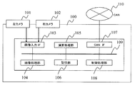
- FIG. 1 is a block diagram showing an overall configuration of a vehicle-mounted stereo camera device 100 (camera device) according to the present embodiment.
- the in-vehicle stereo camera device 100 of the present embodiment is a device mounted on a vehicle and recognizing an environment outside the vehicle based on image information of a shooting target area in front of the vehicle.
- the in-vehicle stereo camera device 100 recognizes, for example, white lines on roads, pedestrians, vehicles, other three-dimensional objects, signals, signs, lighting lamps, and the like, and brakes a vehicle (own vehicle) equipped with the stereo camera device. Perform steering and other adjustments.
- the in-vehicle stereo camera device 100 has two cameras 101 and 102 arranged on the left and right for acquiring image information, and an image input interface 103 for controlling the imaging of the cameras 101 and 102 and capturing the captured image.
- the image captured through this interface is transmitted through a bus 109 and processed by the image processing unit 104 and the arithmetic processing unit 105.
- the results during the processing and the image data as the final result are stored in the storage unit 106. Note that control lines for the cameras 101 and 102 are not shown in FIG.
- the image processing unit 104 compares the first image obtained from the image sensor of the camera 101 with the second image obtained from the image sensor of the camera 102, and determines each image based on the image sensor. Correction of a device-specific deviation and image correction such as noise interpolation are performed and stored in the storage unit 106. Further, the image processing unit 104 calculates a mutually corresponding portion between the first and second images, calculates disparity information, and stores the same in the storage unit 106 as in the above.
- the arithmetic processing unit 105 uses the image and the parallax information (distance information for each point on the image) stored in the storage unit 106 to recognize various objects necessary for perceiving the environment around the vehicle.
- the various objects include a person, a car, other obstacles, a traffic light, a sign, a tail lamp and a head ride of a car, and the like. Some of these recognition results and intermediate calculation results are recorded in the storage unit 106 as in the previous case. After performing various object recognition processes on the captured image, the arithmetic processing unit 105 calculates the control of the vehicle using the recognition results.
- the control policy of the vehicle obtained as a result of the calculation and a part of the object recognition result are transmitted to the in-vehicle network CAN (Controller Area Network) through the CAN interface 107, whereby the vehicle is braked.
- the control processing unit 108 monitors whether or not each processing unit has performed an abnormal operation, whether or not an error has occurred during data transfer, and the like. ).
- the image processing unit 104 includes, via a bus 109 (internal bus), a control processing unit 108, a storage unit 106, an arithmetic processing unit 105, and an image input interface 103 (input and output between the imaging devices of the cameras 101 and 102). ), And a CAN interface 107 (input / output unit with an external vehicle-mounted network).
- the image processing unit 104, the arithmetic processing unit 105, the storage unit 106, the image input interface 103, the CAN interface 107, and the control processing unit 108 are configured by a single or a plurality of computer units.
- the storage unit 106 includes, for example, a memory that stores image information obtained by the image processing unit 104, image information created as a result of scanning by the arithmetic processing unit 105, and the like.
- the CAN interface 107 outputs information output from the in-vehicle stereo camera device 100 to another control system of the vehicle via the CAN 110.
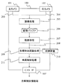
- FIG. 2 shows a processing flow of the vehicle-mounted stereo camera device 100.
- the left and right cameras 101 and 102 capture images.
- the image processing unit 104 absorbs a peculiar habit (image distortion or the like) of the image sensor of the cameras 101 and 102.
- Image processing 205 such as correction is performed.
- the processing result is stored in the image buffer 206.
- the image buffer 206 is provided in the storage unit 106 in FIG.
- the image processing unit 104 performs parallax processing (matching) between the images, thereby performing parallax processing 207 for obtaining parallax information of the images obtained by the left and right cameras. From the parallax between the left and right images, it becomes clear where and how the point of interest on the target object corresponds to the image on the left and right cameras, and the distance to the target can be obtained by the principle of triangulation.
- the image finally obtained by the image processing 205 and the parallax processing 207 and the parallax information are stored in the storage unit 106.
- the arithmetic processing unit 105 performs various object recognition processes 209 using the stored image and the parallax information.
- the object to be recognized includes a person, a car, other three-dimensional objects, a sign, a traffic light, a tail lamp, and the like.
- the arithmetic processing unit 105 uses the recognition dictionary 210 as necessary.
- the arithmetic processing unit 105 performs the vehicle control processing 211 in consideration of the result of the object recognition and the state of the host vehicle (speed, steering angle, etc.). For example, the vehicle control process 211 issues a warning to an occupant, determines a policy of performing braking such as braking or steering angle adjustment of the own vehicle, or determines a policy of performing avoidance control of an object by that. This is the process of outputting through
- the various object recognition processing 209 and the vehicle control processing 211 are performed by the arithmetic processing unit 105 of FIG. 1 as described above, and the output to the CAN is performed by the CAN interface 107.
- Each of these processing means is composed of, for example, a single or a plurality of computer units, and is configured to be able to exchange data with each other.
- FIG. 3 shows a timing chart of the on-vehicle stereo camera device 100.
- a right image input 303 is performed. This corresponds to a process in which the camera 102 (right camera) in FIG. 2 captures an image, passes through image processing 205, and then stores the right image in the image buffer 206 by the image processing unit 104.
- the left image input 304 is performed. This corresponds to the processing from capturing the image by the camera 101 (left camera) in FIG. 2, through the image processing 205, and storing the left image in the image buffer 206 by the image processing unit 104.
- parallax processing 207 is performed.
- the image processing unit 104 reads out two images on the left and right from the image buffer 206, calculates the disparity by comparing the two images, and stores the disparity information obtained by the calculation in the storage unit 106. This is equivalent to the processing up to the storage in. At this point, the image and the parallax information are in the storage unit 106.
- the arithmetic processing unit 105 performs various object recognition processing 209, performs the vehicle control processing 211, and outputs the result to the CAN.
- FIGS. 4A to 4C are diagrams for explaining the processing flow of the sign recognition function.
- the various object recognition processing 209 includes a sign recognition processing 209a.
- the sign recognition process 209a includes a circle detection process 406 and an identification process 407.
- FIG. 4A shows a part of the image stored in the image buffer 206 after the image processing 205.
- FIG. 4B is a processing result obtained by performing image processing on the image of FIG. 4A for use in the sign recognition processing 209a, and is an image having luminance in a portion where the density change is large in the vicinity.
- FIG. 4C is an example of a basic processing flow of sign recognition.
- the circle detection process 406 is performed using the image of FIG. 4B.
- the center of the circle is obtained by the center calculation.
- the circle detection processing 406 is divided into a center estimation step 408 and a radius estimation step 409.
- the center is estimated.
- a line segment 404 is drawn from each edge in the normal direction, and a point where intersections of the line segments overlap by a certain number or more is estimated as the center 400 (FIG. 4A).
- the counting of the number of edges may be omitted from the center 400 to a predetermined radius.
- the calculation omission area can reduce the calculation load. .
- the calculation omission area may be reduced.
- detection of a sign in the shape of a circle has been described as an example, but signs such as a rectangle, an octagon, and a triangle can also be detected in the graphic detection processing described later.
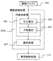
- FIG. 5 shows a processing flow for detecting a regulation release sign in the embodiment of the present invention.
- the search for the regulation release sign (regulation end sign) is performed at the timing of the sign recognition processing 209a in the various object recognition processing 209.
- a group of sign candidates called main signs such as speed signs and overtaking prohibitions is extracted by first performing graphic detection 502 from the image buffer 501 storing the image of the target frame.
- the respective patterns are cut out from the image and identification 503 is performed.
- the recognition dictionary 210 is used, and the type of the sign is identified by combining a weak classifier such as a binary discriminant tree and a strong classifier such as a nearest neighbor method or a discriminant function.
- the arithmetic processing unit 105 functions as a main marker identifying unit that identifies the main marker.
- the unique processing for the restriction release sign includes a diagonal line search 504, a diagonal line determination 505, and an identification processing 506 for the restriction release sign.
- the diagonal line search 504 is a process of detecting a diagonal line portion at the center of the restriction release marker based on an edge image obtained by extracting an edge component from a frame image to be recognized.
- the arithmetic processing unit 105 functions as a search unit that searches for an oblique line candidate from an image. By searching for a hatched line which is a characteristic design of the regulation release sign, the detection accuracy of the regulation release sign can be improved.
- the arithmetic processing unit 105 (search unit) searches for a diagonal line candidate, for example, in response to the identification of the real sign. Thereby, the oblique line of the regulation release sign co-occurring with the present sign can be detected in a timely manner.
- the specific contents of the processing are described in FIG.
- the oblique line determination 505 is a process for determining, from the detected oblique line candidates, oblique lines considered to be signs and oblique lines considered to be electric wires or pillars.
- the arithmetic processing unit 105 functions as a selection unit that selects, from the detected diagonal line candidates, a diagonal line candidate of a restriction release marker indicating release of the restriction corresponding to the real marker. This will be described later with reference to FIG.
- the identification process 506 is a process of identifying the restriction release marker from the image of the selected hatched candidate of the restriction release marker.
- the arithmetic processing unit 105 functions as a regulation release marker identification unit that performs the identification process 506.
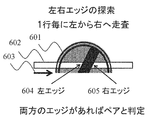
- FIG. 6A is a diagram showing an outline of a process of the oblique line search 504 (oblique line detection) shown in FIG.
- a horizontal scanning line 602 is determined for the image 601 of the target regulation release marker, and image scanning is performed in a direction 603, such as left to right.
- the image to be scanned is an edge image.
- the deregulation sign has a distinctive design in Europe, Japan and elsewhere.
- the left edge 604 and the right edge 605 of this oblique line are determined, and an edge pair is determined by utilizing the fact that the left edge and the right edge are within a certain distance.
- the arithmetic processing unit 105 scans the image in the horizontal direction, searches for a pair of a left edge and a right edge, and detects two or more pairs arranged continuously as oblique line candidates. By searching for a pair of a left edge and a right edge of at least two pixels or more, it is possible to narrow down the oblique line candidates of the restriction release sign. Note that a pair of a left edge and a right edge as oblique line candidates are continuously arranged adjacently without any gap.
- the distance (horizontal length) to be determined in the edge pair is determined by a certain range from the size of the main sign which triggered the search for the regulation release sign, or the distance to the target sign in the case of a stereo camera. It is also possible to convert using.
- the storage unit 106 stores the size of the main sign and the range of the length of the hatched horizontal direction of the restriction release sign in association with each other.
- the arithmetic processing unit 105 (search unit) determines that the distance between the left edge and the right edge is within the range of the horizontal length of the oblique line of the restriction release marker associated with the size of the main marker. Search for a pair. Thereby, the diagonal line candidates can be narrowed down by the horizontal length of the diagonal line of the restriction release marker according to the size of the real sign.
- diagonal candidates are narrowed down by the length of the continuous edge pairs.
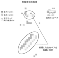
- the narrowing down (selection) of diagonal line candidates will be described with reference to FIG.
- the output information of the diagonal line search includes the position, length, intensity, contrast ratio with the peripheral portion, color component, and line thickness of the edge pair.
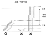
- the diagonal line determination (upper limit / lower limit determination) in FIG. 7 is a process of determining a diagonal line that seems to be a design in a sign and a diagonal line component such as an electric wire or a pillar that is not related to the sign.
- the basic idea is determined by using the length and thickness of the edge pair, the contrast ratio with the periphery, the color, and the like.
- the length has an upper limit and a lower limit. Edge pairs exceeding the upper limit length are regarded as long diagonal lines such as telephone poles and are excluded, and edge pairs below the lower limit length are regarded as short diagonal lines such as patterns and excluded.
- the storage unit 106 stores the size of the permanent sign and the range of the length of the hatched vertical direction of the restriction release sign in association with each other.
- the arithmetic processing unit 105 selects a diagonal line candidate whose vertical length of the detected diagonal line candidate is within the range of the vertical length of the diagonal line of the restriction release marker associated with the size of the main sign. I do. Thereby, it is possible to prevent erroneous detection of the hatching of the regulation release sign.
- the question is how to set the upper and lower limits. This is set based on the size of the main sign which has triggered the search for the regulation release sign. In general, the size of the sign and the size range allowed for the deregulation sign are defined by the driving region and country. Using this information, the upper and lower limits of the size permitted as the deregulation sign are determined from the size of the sign. Can be estimated. As shown in FIG. 8, information on the traveling area can be obtained in cooperation with an external position information system.
- the storage unit 106 may further store information indicating the relative position of the regulation release marker with respect to the position of the main marker.
- the arithmetic processing unit 105 (processor) searches for a diagonal line candidate from an image area corresponding to the relative position of the restriction release marker with respect to the identified position of the official marker (for example, above the official marker in Japan).
- the area for searching for the hatched candidate for the regulation release sign is limited.
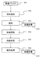
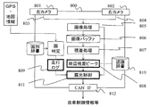
- FIG. 8 is a diagram for explaining a mechanism (configuration) for obtaining an opportunity to search for a regulation release sign in cooperation with GPS and map information.
- ⁇ Image processing 805 is performed with the left camera 801 and the right camera 802 as starting points, and a parallax processing 807 detects a three-dimensional object on a side road such as a forest or a forest by looking at an area around the traveling road. Furthermore, the latitude and longitude information is obtained from the GPS, and the data of the border is stored inside the stereo camera, so that the current traveling area is determined by the country determination process. Further, information such as which country the vehicle is running, the current direction to which the vehicle is heading, and the running time zone is obtained from the running log 809.
- the external position information sensor has further high-definition map information or section information on road speed regulation, the appearance position of the sign and the switching position of the speed regulation can be known. Search is possible.
- the exposure control 811 can be performed.
- the co-occurrence status of the regulation release sign was used by changing the ratio of the processing time devoted to searching for edge pairs at the switching position of the appearance position of the sign and the speed section of the road Searching can be performed.
- the storage unit 106 stores information indicating the relative position of the restriction release sign with respect to the position of the main sign for each travel location area.
- the arithmetic processing unit 105 searches for a diagonal line candidate from the area of the image corresponding to the relative position of the regulation release sign for each travel location area with respect to the position of the identified real sign. This limits the area in which to search for a diagonal line candidate for a regulation release sign according to the traveling area. As a result, it is possible to efficiently search for a hatched candidate for a regulation release sign.
- the sign and the deregulation sign do not co-occur, and the location of the sign is different from the place of the deregulation sign.
- the arithmetic processing unit 105 search unit determines the distance from the area of the image corresponding to the position (forward) separated by the length of the section from the main sign. You may search for a diagonal line candidate.
- the detection accuracy of the regulation release sign can be improved.
- the above-described configurations, functions, and the like may be partially or entirely realized by hardware, for example, by designing an integrated circuit.
- the above-described configurations, functions, and the like may be realized by software by a processor interpreting and executing a program that realizes each function.
- Information such as a program, a table, and a file for realizing each function can be stored in a memory, a hard disk, a recording device such as an SSD (Solid State Drive), or a recording medium such as an IC card, an SD card, or a DVD.
- a circular object information acquisition unit that obtains information on a circular object from an image (circle detection unit), an identification unit that identifies a first sign for the circular object obtained by the circular object information acquisition unit, and the circular object from the image
- a search unit that searches for a tilted object around the object, information on the tilted object obtained by the search unit, and information on the first sign obtained by the identification unit, based on the second sign related to the tilted object
- a camera device comprising: a determination unit that performs a determination.
- the front search unit searches for a pair of a left edge and a right edge in a horizontal direction of the image, and the pair of the left edge and the right edge forms a slope that is continuous in a vertical direction.
- the determination unit determines the second marker with respect to the inclined object based on an upper limit and a lower limit corresponding to the first marker with respect to the circular object.
Abstract
The present invention provides a camera device with which it is possible to improve the accuracy of detecting a restriction removal sign. An arithmetic processing unit (search unit) searches for a diagonal line candidate from an image (diagonal line search 504). The arithmetic processing unit (selection unit) selects the diagonal line candidate of a restriction removal sign indicating the removal of restriction, the diagonal line candidate corresponding to the actual sign, from the detected diagonal line candidates (diagonal line determination 505). The arithmetic processing unit (restriction removal sign identification unit) identifies a restriction removal sign from the images of selected diagonal line candidate of the restriction removal sign (identification process 506).
Description
本発明は、カメラ装置に関する。
The present invention relates to a camera device.
近年、車載カメラ装置の普及により、安全運転や自動運転に向けた各種認識機能への要求が高まってきている。なかでも、ステレオカメラ装置は、画像による視覚的な情報と、対象物への距離情報を同時に計測するため、自動車周辺の様々な対象物(人、車、立体物、路面、路面標識、看板標識など)を詳細に把握でき、運転支援時の安全性の向上にも寄与するとされている。
In recent years, the demand for various recognition functions for safe driving and automatic driving has been increasing due to the spread of in-vehicle camera devices. In particular, a stereo camera device measures various objects (people, cars, three-dimensional objects, road surfaces, road signs, road signs, signboard signs, etc.) around an automobile in order to simultaneously measure visual information by images and distance information to the objects. Etc.) can be understood in detail, which also contributes to improving safety during driving assistance.
国内外で標識認識機能の要求が高まり、認識精度の向上が求められている。精度劣化要因のひとつとして、規制解除標識の検知・認識の困難さがある。これは規制解除標識のデザインが速度標識などと違い、サイズが小さ目なこと、周辺の円環の幅が小さいため背景との十分なコントラスト差が出にくいといった事に起因して、検知が難しいためである。規制解除標識が検知・認識できなかった結果、規制速度表示を終了すべき状況においても、前回の表示を継続してしまうため、ドライバに対して正しい速度情報を提供する点において課題を生じてしまう。
標識 There is an increasing demand for sign recognition functions in Japan and overseas, and there is a need for improved recognition accuracy. One of the causes of accuracy deterioration is the difficulty in detecting and recognizing the regulation release sign. This is because it is difficult to detect, because the design of the regulation release sign is different from the speed sign etc., because the size is small and the surrounding ring is so narrow that it is difficult to obtain a sufficient contrast difference with the background. It is. As a result of not being able to detect / recognize the regulation release sign, the previous display is continued even in the situation where the regulation speed display should be terminated, thus causing a problem in providing correct speed information to the driver. .
従来から、車両に搭載され、車両の前方の状況を認識する車載カメラ装置に関する様々な技術・装置が提案されてきた。例えば、標識認識の性能向上に関しては、認識の高精度化を図るという点に着目した技術として、特許文献1がある。
Conventionally, various technologies and devices related to an in-vehicle camera device mounted on a vehicle and recognizing a situation in front of the vehicle have been proposed. For example, with respect to improving the performance of sign recognition, Patent Literature 1 discloses a technique that focuses on improving recognition accuracy.
しかしながら、特許文献1に開示されるような技術では、精度劣化要因のひとつとして、速度規制などの規制の解除を指示する標識(規制解除標識)を未検知となる課題がある。
However, the technology disclosed in Patent Document 1 has a problem that one of the factors of accuracy deterioration is that a sign (regulation release sign) for instructing cancellation of regulation such as speed regulation is not detected.
本発明の目的は、上記の点に鑑みてなされたものであり、その目的とするところは、規制解除標識の検知精度を向上することができるカメラ装置を提供することである。
目的 An object of the present invention has been made in view of the above points, and an object of the present invention is to provide a camera device capable of improving the detection accuracy of a regulation release sign.
上記目的を達成するために、本発明は、画像から斜線候補を探索する探索部と、検出された前記斜線候補から本標識に対応する規制の解除を示す規制解除標識の斜線候補を選択する選択部と、選択された前記規制解除標識の前記斜線候補の前記画像から前記規制解除標識を識別する規制解除標識識別部と、を備える。
In order to achieve the above object, the present invention provides a search unit that searches for a diagonal line candidate from an image, and a selection unit that selects, from the detected diagonal line candidates, a diagonal line candidate of a restriction release marker indicating release of restriction corresponding to the real sign. And a restriction release sign identifying unit that identifies the restriction release sign from the image of the hatched candidate of the selected restriction release sign.
本発明によれば、規制解除標識の検知精度を向上することができる。上記した以外の課題、構成及び効果は、以下の実施形態の説明により明らかにされる。
According to the present invention, the detection accuracy of the regulation release sign can be improved. Problems, configurations, and effects other than those described above will be apparent from the following description of the embodiments.
本発明の実施形態について図を用いて以下に説明する。なお、前述した発明の目的と一部重複するが、本実施形態の目的は、標識の検知処理において、規制解除のデザインに沿った検知を行い、かつ木や電信柱などのパタンとの誤判定を抑制することが可能なカメラ装置を提供することである。
実 施 An embodiment of the present invention will be described below with reference to the drawings. Although partially overlapping with the object of the invention described above, the object of the present embodiment is to perform detection in accordance with the design of the regulation release in the sign detection processing, and to erroneously determine a pattern such as a tree or a telephone pole. It is an object of the present invention to provide a camera device capable of suppressing the above.
図1は、本実施形態にかかわる車載ステレオカメラ装置100(カメラ装置)の全体構成を示すブロック図である。本実施形態の車載ステレオカメラ装置100は、車両に搭載され、車両前方の撮影対象領域の画像情報に基づいて車外環境を認識する装置である。車載ステレオカメラ装置100は、例えば、道路の白線、歩行者、車両、その他の立体物、信号、標識、点灯ランプなどの認識を行い、当該ステレオカメラ装置を搭載した車両(自車両)のブレーキ、ステアリングなどの調整を行う。
FIG. 1 is a block diagram showing an overall configuration of a vehicle-mounted stereo camera device 100 (camera device) according to the present embodiment. The in-vehicle stereo camera device 100 of the present embodiment is a device mounted on a vehicle and recognizing an environment outside the vehicle based on image information of a shooting target area in front of the vehicle. The in-vehicle stereo camera device 100 recognizes, for example, white lines on roads, pedestrians, vehicles, other three-dimensional objects, signals, signs, lighting lamps, and the like, and brakes a vehicle (own vehicle) equipped with the stereo camera device. Perform steering and other adjustments.
車載ステレオカメラ装置100は、画像情報を取得する左右に配置された2つのカメラ101、102と、カメラ101、102の撮像を制御して、撮像した画像を取り込むための画像入力インタフェース103を持つ。このインタフェースを通して取り込まれた画像は、バス109を通してデータが送られ、画像処理部104や、演算処理部105で処理される。処理途中の結果や最終結果となる画像データなどは記憶部106に記憶される。なお、図面を見やすくするため、図1においてカメラ101、102等の制御線は表示していない。
The in-vehicle stereo camera device 100 has two cameras 101 and 102 arranged on the left and right for acquiring image information, and an image input interface 103 for controlling the imaging of the cameras 101 and 102 and capturing the captured image. The image captured through this interface is transmitted through a bus 109 and processed by the image processing unit 104 and the arithmetic processing unit 105. The results during the processing and the image data as the final result are stored in the storage unit 106. Note that control lines for the cameras 101 and 102 are not shown in FIG.
画像処理部104は、カメラ101の撮像素子から得られる第1の画像と、カメラ102の撮像素子から得られる第2の画像とを比較して、それぞれの画像に対して、撮像素子に起因するデバイス固有の偏差の補正や、ノイズ補間などの画像補正を行い、これを記憶部106に記憶する。更に、画像処理部104は、第1および第2の画像の間で、相互に対応する箇所を計算して、視差情報を計算し、先程と同様に、これを記憶部106に記憶する。
The image processing unit 104 compares the first image obtained from the image sensor of the camera 101 with the second image obtained from the image sensor of the camera 102, and determines each image based on the image sensor. Correction of a device-specific deviation and image correction such as noise interpolation are performed and stored in the storage unit 106. Further, the image processing unit 104 calculates a mutually corresponding portion between the first and second images, calculates disparity information, and stores the same in the storage unit 106 as in the above.
演算処理部105は、記憶部106に蓄えられた画像および視差情報(画像上の各点に対する距離情報)を使い、車両周辺の環境を知覚するために必要な、各種物体の認識を行う。各種物体とは、人、車、その他の障害物、信号機、標識、車のテールランプやヘッドライド、などである。これら認識結果や中間的な計算結果の一部が、先程と同様に記憶部106に記録される。演算処理部105は、撮像した画像に対して各種物体認識処理を行った後に、これら認識結果を用いて車両の制御を計算する。
The arithmetic processing unit 105 uses the image and the parallax information (distance information for each point on the image) stored in the storage unit 106 to recognize various objects necessary for perceiving the environment around the vehicle. The various objects include a person, a car, other obstacles, a traffic light, a sign, a tail lamp and a head ride of a car, and the like. Some of these recognition results and intermediate calculation results are recorded in the storage unit 106 as in the previous case. After performing various object recognition processes on the captured image, the arithmetic processing unit 105 calculates the control of the vehicle using the recognition results.
計算の結果として得られた車両の制御方針や、物体認識結果の一部はCANインタフェース107を通して、車載ネットワークCAN(Controller Area Network)に伝えられ、これにより車両の制動が行われる。また、これらの動作について、各処理部が異常動作を起こしていないか、データ転送時にエラーが発生していないかどうかなどを、制御処理部108が監視しており、異常動作を防ぐ仕掛け(構成)となっている。
The control policy of the vehicle obtained as a result of the calculation and a part of the object recognition result are transmitted to the in-vehicle network CAN (Controller Area Network) through the CAN interface 107, whereby the vehicle is braked. In addition, regarding these operations, the control processing unit 108 monitors whether or not each processing unit has performed an abnormal operation, whether or not an error has occurred during data transfer, and the like. ).
上記の画像処理部104は、バス109(内部バス)を介して、制御処理部108、記憶部106、演算処理部105、画像入力インタフェース103(カメラ101、102の撮像素子との間の入出力部)、CANインタフェース107(外部車載ネットワークとの入出力部)に接続されている。
The image processing unit 104 includes, via a bus 109 (internal bus), a control processing unit 108, a storage unit 106, an arithmetic processing unit 105, and an image input interface 103 (input and output between the imaging devices of the cameras 101 and 102). ), And a CAN interface 107 (input / output unit with an external vehicle-mounted network).
画像処理部104、演算処理部105、記憶部106、画像入力インタフェース103、CANインタフェース107、及び制御処理部108は、単一または複数のコンピュータユニットにより構成されている。記憶部106は、例えば画像処理部104によって得られた画像情報や、演算処理部105によって走査された結果作られた画像情報等を記憶するメモリ等により構成されている。CANインタフェース107は、車載ステレオカメラ装置100から出力する情報を、CAN110を介して自車両の他の制御システムに出力する。
The image processing unit 104, the arithmetic processing unit 105, the storage unit 106, the image input interface 103, the CAN interface 107, and the control processing unit 108 are configured by a single or a plurality of computer units. The storage unit 106 includes, for example, a memory that stores image information obtained by the image processing unit 104, image information created as a result of scanning by the arithmetic processing unit 105, and the like. The CAN interface 107 outputs information output from the in-vehicle stereo camera device 100 to another control system of the vehicle via the CAN 110.
図2に車載ステレオカメラ装置100の処理フローを示す。
FIG. 2 shows a processing flow of the vehicle-mounted stereo camera device 100.
左右のカメラ101、102は、画像を撮像する。左右のカメラ101、102の各々で撮像された画像データ203、204のそれぞれについて、画像処理部104は、カメラ101、102の撮像素子が持つ固有の癖(画像の歪み等)を吸収するための補正などの画像処理205を行う。その処理結果は画像バッファ206に蓄えられる。画像バッファ206は、図1の記憶部106に設けられる。
The left and right cameras 101 and 102 capture images. For each of the image data 203 and 204 captured by each of the left and right cameras 101 and 102, the image processing unit 104 absorbs a peculiar habit (image distortion or the like) of the image sensor of the cameras 101 and 102. Image processing 205 such as correction is performed. The processing result is stored in the image buffer 206. The image buffer 206 is provided in the storage unit 106 in FIG.
更に、補正された2つの画像を使って、画像処理部104は、画像同士の照合(マッチング)を行い、これにより左右カメラで得た画像の視差情報を得る視差処理207を行う。左右画像の視差により、対象物体上のある着目点が、左右カメラの画像上の何処と何処に対応するかが明らかとなり、三角測量の原理によって、対象物までの距離が得られることになる。画像処理205および視差処理207で最終的に得られた画像、および視差情報は記憶部106に蓄えられる。
{Circle around (2)} Using the two corrected images, the image processing unit 104 performs parallax processing (matching) between the images, thereby performing parallax processing 207 for obtaining parallax information of the images obtained by the left and right cameras. From the parallax between the left and right images, it becomes clear where and how the point of interest on the target object corresponds to the image on the left and right cameras, and the distance to the target can be obtained by the principle of triangulation. The image finally obtained by the image processing 205 and the parallax processing 207 and the parallax information are stored in the storage unit 106.
更に上記の記憶された画像、および視差情報を用いて、演算処理部105は、各種物体認識処理209を行う。認識対象の物体としては、人、車、その他の立体物、標識、信号機、テールランプなどがあるが、認識の際、演算処理部105は必要に応じて認識辞書210を利用する。
Furthermore, the arithmetic processing unit 105 performs various object recognition processes 209 using the stored image and the parallax information. The object to be recognized includes a person, a car, other three-dimensional objects, a sign, a traffic light, a tail lamp, and the like. At the time of recognition, the arithmetic processing unit 105 uses the recognition dictionary 210 as necessary.
更に、物体認識の結果と、自車両の状態(速度、舵角など)とを勘案して、演算処理部105は、車両制御処理211を行う。車両制御処理211は、例えば、乗員に警告を発し、自車両のブレーキングや舵角調整などの制動を行う、あるいは、それによって対象物の回避制御を行う方針を決め、その結果をCANインタフェース107を通して出力する処理である。
Further, the arithmetic processing unit 105 performs the vehicle control processing 211 in consideration of the result of the object recognition and the state of the host vehicle (speed, steering angle, etc.). For example, the vehicle control process 211 issues a warning to an occupant, determines a policy of performing braking such as braking or steering angle adjustment of the own vehicle, or determines a policy of performing avoidance control of an object by that. This is the process of outputting through
なお、各種物体認識処理209および車両制御処理211は、前述したように図1の演算処理部105で行われ、CANへの出力は、CANインタフェース107にて行われる。これらの各処理各手段は、例えば単一または複数のコンピュータユニットにより構成され、相互にデータを交換可能に構成されている。
The various object recognition processing 209 and the vehicle control processing 211 are performed by the arithmetic processing unit 105 of FIG. 1 as described above, and the output to the CAN is performed by the CAN interface 107. Each of these processing means is composed of, for example, a single or a plurality of computer units, and is configured to be able to exchange data with each other.
図3に車載ステレオカメラ装置100のタイミングチャートを示す。
FIG. 3 shows a timing chart of the on-vehicle stereo camera device 100.
図3のタイミングチャートでは大きく2系統の流れを301、302として示している。301の流れが、図1の画像処理部104における処理タイミングであり、302の流れが、図1の演算処理部105における処理タイミングを示している。まず、右画像入力303が行われる。これは、図2におけるカメラ102(右カメラ)が画像撮像を行い、その後で画像処理205を経て、画像処理部104が画像バッファ206に右画像を蓄えるまでの処理に相当する。
{Circle around (2)} in the timing chart of FIG. The flow of 301 indicates the processing timing in the image processing unit 104 of FIG. 1, and the flow of 302 indicates the processing timing of the arithmetic processing unit 105 in FIG. First, a right image input 303 is performed. This corresponds to a process in which the camera 102 (right camera) in FIG. 2 captures an image, passes through image processing 205, and then stores the right image in the image buffer 206 by the image processing unit 104.
次に左画像入力304が行われる。これは、図2におけるカメラ101(左カメラ)が画像撮像を行い、画像処理205を経て、画像処理部104が画像バッファ206に左画像を蓄えるまでの処理に該当する。次に視差処理207が行われる。これは、図2において、画像バッファ206から左右の2つの画像を画像処理部104が読み出し、両画像間の照合を取ることで視差を計算し、計算して得られた視差情報を記憶部106に蓄えるまでの処理に相当する。この時点で、画像と視差情報が記憶部106に揃ったことになる。次に演算処理部105が各種物体認識処理209を行い、車両制御処理211を行い、その結果をCANに出力する運びとなる。
Next, the left image input 304 is performed. This corresponds to the processing from capturing the image by the camera 101 (left camera) in FIG. 2, through the image processing 205, and storing the left image in the image buffer 206 by the image processing unit 104. Next, parallax processing 207 is performed. In FIG. 2, the image processing unit 104 reads out two images on the left and right from the image buffer 206, calculates the disparity by comparing the two images, and stores the disparity information obtained by the calculation in the storage unit 106. This is equivalent to the processing up to the storage in. At this point, the image and the parallax information are in the storage unit 106. Next, the arithmetic processing unit 105 performs various object recognition processing 209, performs the vehicle control processing 211, and outputs the result to the CAN.
図4A~図4Cは、標識認識機能の処理フローを説明するための図である。
FIGS. 4A to 4C are diagrams for explaining the processing flow of the sign recognition function.
各種物体認識処理209は、標識認識処理209aを含む。標識認識処理209aは、円検知処理406と識別処理407からなる。図4Aは、画像処理205を経て、画像バッファ206に蓄えられた画像の一部である。図4Bは、標識認識処理209aで使用するために、図4Aの画像を画像処理した処理結果であり、近傍での濃淡変化が大きい部分に輝度を持つ画像である。図4Cは、標識認識の基本処理フローの一例である。
The various object recognition processing 209 includes a sign recognition processing 209a. The sign recognition process 209a includes a circle detection process 406 and an identification process 407. FIG. 4A shows a part of the image stored in the image buffer 206 after the image processing 205. FIG. 4B is a processing result obtained by performing image processing on the image of FIG. 4A for use in the sign recognition processing 209a, and is an image having luminance in a portion where the density change is large in the vicinity. FIG. 4C is an example of a basic processing flow of sign recognition.
標識認識処理209aでは、まず、図4Bの画像を用い、円検知処理406を行う。円検知処理406では、中心演算により円の中心を求める。円検知処理406は、中心推定のステップ408と半径推定のステップ409に分けられる。
In the marker recognition process 209a, first, the circle detection process 406 is performed using the image of FIG. 4B. In the circle detection processing 406, the center of the circle is obtained by the center calculation. The circle detection processing 406 is divided into a center estimation step 408 and a radius estimation step 409.
はじめに、ステップ408において、中心の推定を行う。各エッジから法線方向に線分404を引き、その線分の交点が一定数以上重なる点を中心400(図4A)と推定する。なお、中心400から所定半径まではエッジ数のカウントを省略してもよい。標識は一般的に、直径30cm以上であることや、非常に遠くにある標識を検知しても識別処理407で処理できない場合を鑑みて、この演算省略領域により、演算負荷を低減することができる。
First, in step 408, the center is estimated. A line segment 404 is drawn from each edge in the normal direction, and a point where intersections of the line segments overlap by a certain number or more is estimated as the center 400 (FIG. 4A). The counting of the number of edges may be omitted from the center 400 to a predetermined radius. In general, in consideration of a sign having a diameter of 30 cm or more and a sign that cannot be processed by the identification processing 407 even if a sign that is very far is detected, the calculation omission area can reduce the calculation load. .
なお、標識認識処理209aを行うプロセッサ等のハードウェアの処理能力の向上により、非常に遠くにある標識を認識して安全性を向上させるために、演算省略領域を小さくしてもよい。この例では丸形状の標識検知を例に説明したが、後述する図形検知処理においては矩形、八角形、三角形などの標識も検知可能である。
In order to improve the security by recognizing an extremely distant sign by improving the processing capability of hardware such as a processor that performs the sign recognition process 209a, the calculation omission area may be reduced. In this example, detection of a sign in the shape of a circle has been described as an example, but signs such as a rectangle, an octagon, and a triangle can also be detected in the graphic detection processing described later.
図5に本発明の実施形態における規制解除標識検知の処理フローを示す。
FIG. 5 shows a processing flow for detecting a regulation release sign in the embodiment of the present invention.
規制解除標識(規制終了標識)の探索は、各種物体認識処理209の中の標識認識処理209aのタイミングにて行われる。標識認識処理209aでは、対象とするフレームの画像を格納した画像バッファ501から、まず図形検知502を行う事によって、速度標識や追い越し禁止などの本標識と呼ばれる標識候補群を抽出する。
The search for the regulation release sign (regulation end sign) is performed at the timing of the sign recognition processing 209a in the various object recognition processing 209. In the sign recognition process 209a, a group of sign candidates called main signs such as speed signs and overtaking prohibitions is extracted by first performing graphic detection 502 from the image buffer 501 storing the image of the target frame.
次に抽出した複数の標識候補に対して、各々のパタンを画像から切出して識別503を行う。識別を行う際には認識辞書210が用いられ、二項判別木のような弱識別器、最近傍法や判別関数などの強識別器などを組み合わせて、標識の種類を同定する。
(4) For the plurality of extracted marker candidates, the respective patterns are cut out from the image and identification 503 is performed. When performing identification, the recognition dictionary 210 is used, and the type of the sign is identified by combining a weak classifier such as a binary discriminant tree and a strong classifier such as a nearest neighbor method or a discriminant function.
ここで、演算処理部105(プロセッサ)は、本標識を識別する本標識識別部として機能する。
Here, the arithmetic processing unit 105 (processor) functions as a main marker identifying unit that identifies the main marker.
次に、識別した標識のうち、規制解除標識と共起関係で出現しやすい標識が検知された場合においては、以下で説明するように、規制解除標識の検知・判定に適した独自処理を行う。規制解除標識に向けた独自処理は、斜線探索504、斜線判定505、規制解除標識向けの識別処理506から構成される。
Next, if a sign that is likely to appear in a co-occurrence relationship with the regulation release sign is detected from the identified signs, as described below, an independent process suitable for detecting and determining the regulation release sign is performed. . The unique processing for the restriction release sign includes a diagonal line search 504, a diagonal line determination 505, and an identification processing 506 for the restriction release sign.
斜線探索504は、認識対象であるフレーム画像からエッジ成分を抽出したエッジ画像を元に、規制解除標識の中央部分にある斜線部分を検知する処理である。ここで、演算処理部105(プロセッサ)は、画像から斜線候補を探索する探索部として機能する。規制解除標識の特徴的なデザインである斜線を探索することで規制解除標識の検知精度を向上することができる。なお、演算処理部105(探索部)は、例えば、本標識が識別されたことを契機として、斜線候補を探索する。これにより、本標識と共起する規制解除標識の斜線を適時に検知することができる。処理の具体的な内容は図6に記述する。
The diagonal line search 504 is a process of detecting a diagonal line portion at the center of the restriction release marker based on an edge image obtained by extracting an edge component from a frame image to be recognized. Here, the arithmetic processing unit 105 (processor) functions as a search unit that searches for an oblique line candidate from an image. By searching for a hatched line which is a characteristic design of the regulation release sign, the detection accuracy of the regulation release sign can be improved. The arithmetic processing unit 105 (search unit) searches for a diagonal line candidate, for example, in response to the identification of the real sign. Thereby, the oblique line of the regulation release sign co-occurring with the present sign can be detected in a timely manner. The specific contents of the processing are described in FIG.
また、斜線判定505は、検出した斜線候補のなかから、標識と思われる斜線と、電線や柱などと思われる斜線を判別するための処理である。ここで、演算処理部105(プロセッサ)は、検出された斜線候補から本標識に対応する規制の解除を示す規制解除標識の斜線候補を選択する選択部として機能する。これについては図7を用いて後述する。
The oblique line determination 505 is a process for determining, from the detected oblique line candidates, oblique lines considered to be signs and oblique lines considered to be electric wires or pillars. Here, the arithmetic processing unit 105 (processor) functions as a selection unit that selects, from the detected diagonal line candidates, a diagonal line candidate of a restriction release marker indicating release of the restriction corresponding to the real marker. This will be described later with reference to FIG.
さらに、識別処理506は、選択された規制解除標識の斜線候補の画像から規制解除標識を識別する処理である。演算処理部105(プロセッサ)は、識別処理506を行う規制解除標識識別部として機能する。
識別 Furthermore, the identification process 506 is a process of identifying the restriction release marker from the image of the selected hatched candidate of the restriction release marker. The arithmetic processing unit 105 (processor) functions as a regulation release marker identification unit that performs the identification process 506.
図6Aは、図5に示す斜線探索504(斜線検知)の処理概要を示した図である。
FIG. 6A is a diagram showing an outline of a process of the oblique line search 504 (oblique line detection) shown in FIG.
対象とする規制解除標識の画像例601に対して、横方向の走査ライン602を定め、左から右など一方向603に定めた方向で画像走査を行う。走査する画像はエッジ画像である。規制解除標識は、欧州や日本などにおいては斜線の存在が特徴立ったデザインとなっている。エッジの方向・強度を見ることにより、この斜線の左エッジ604と、右エッジ605を判別し、さらに左エッジと右エッジが一定距離内にあることを利用してエッジペアを判定する。
(4) A horizontal scanning line 602 is determined for the image 601 of the target regulation release marker, and image scanning is performed in a direction 603, such as left to right. The image to be scanned is an edge image. The deregulation sign has a distinctive design in Europe, Japan and elsewhere. By observing the direction and intensity of the edge, the left edge 604 and the right edge 605 of this oblique line are determined, and an edge pair is determined by utilizing the fact that the left edge and the right edge are within a certain distance.
ここで、演算処理部105(探索部)は、画像を横方向に走査し、左エッジと右エッジのペアを探索し、連続して配置される2以上のペアを斜線候補として検出する。少なくとも2画素以上の左エッジと右エッジのペアを探索することで規制解除標識の斜線候補を絞ることができる。なお、斜線候補としての左エッジと右エッジのペアは隙間なく隣接しながら連続して配置される。
Here, the arithmetic processing unit 105 (search unit) scans the image in the horizontal direction, searches for a pair of a left edge and a right edge, and detects two or more pairs arranged continuously as oblique line candidates. By searching for a pair of a left edge and a right edge of at least two pixels or more, it is possible to narrow down the oblique line candidates of the restriction release sign. Note that a pair of a left edge and a right edge as oblique line candidates are continuously arranged adjacently without any gap.
エッジペアにおいて判定する距離(横方向の長さ)は、規制解除標識の探索の契機とした本標識のサイズから一定範囲を定めることや、あるいはステレオカメラであれば対象標識とする標識までの距離を使って換算する事も可能である。
The distance (horizontal length) to be determined in the edge pair is determined by a certain range from the size of the main sign which triggered the search for the regulation release sign, or the distance to the target sign in the case of a stereo camera. It is also possible to convert using.
詳細には、記憶部106は、本標識のサイズと規制解除標識の斜線の横方向の長さの範囲とを関連付けて記憶する。演算処理部105(探索部)は、左エッジと右エッジとの間の距離が本標識のサイズに関連付けられた規制解除標識の斜線の横方向の長さの範囲内にある左エッジと右エッジのペアを探索する。これにより、本標識のサイズに応じた規制解除標識の斜線の横方向の長さで斜線候補を絞ることができる。
Specifically, the storage unit 106 stores the size of the main sign and the range of the length of the hatched horizontal direction of the restriction release sign in association with each other. The arithmetic processing unit 105 (search unit) determines that the distance between the left edge and the right edge is within the range of the horizontal length of the oblique line of the restriction release marker associated with the size of the main marker. Search for a pair. Thereby, the diagonal line candidates can be narrowed down by the horizontal length of the diagonal line of the restriction release marker according to the size of the real sign.
更に抽出したエッジペアについては、図6Bのように、連続するエッジペアの長さによって斜線の候補を絞り込む。斜線の候補の絞り込み(選択)については、図7を用いて説明する。斜線探索(斜線検知)の出力情報としては、エッジペアの位置、長さ、強度、および周辺部分とのコントラスト比、色成分、線の太さなどがある。
(6) With respect to the extracted edge pairs, as shown in FIG. 6B, diagonal candidates are narrowed down by the length of the continuous edge pairs. The narrowing down (selection) of diagonal line candidates will be described with reference to FIG. The output information of the diagonal line search (diagonal line detection) includes the position, length, intensity, contrast ratio with the peripheral portion, color component, and line thickness of the edge pair.
図7の斜線判定(上限・下限判定)は、標識内のデザインと思われる斜線と、電線や柱などの、標識とは関係ない斜線成分とを判定する処理である。基本的な考え方はエッジペアの長さ、太さ、周辺とのコントラスト比、色味などを利用して判断する。
(7) The diagonal line determination (upper limit / lower limit determination) in FIG. 7 is a process of determining a diagonal line that seems to be a design in a sign and a diagonal line component such as an electric wire or a pillar that is not related to the sign. The basic idea is determined by using the length and thickness of the edge pair, the contrast ratio with the periphery, the color, and the like.
図7では、長さによる考え方を述べている。長さには上限と下限があり、上限長を上回るエッジペアについては電柱など長い斜線と見なしてこれを除外し、また下限長を下回るエッジペアについては模様など短い斜線と見なしてこれを除外する。
In Fig. 7, the concept based on length is described. The length has an upper limit and a lower limit. Edge pairs exceeding the upper limit length are regarded as long diagonal lines such as telephone poles and are excluded, and edge pairs below the lower limit length are regarded as short diagonal lines such as patterns and excluded.
詳細には、記憶部106は、本標識のサイズと規制解除標識の斜線の縦方向の長さの範囲とを関連付けて記憶する。演算処理部105(選択部)は、検出された斜線候補の縦方向の長さが本標識のサイズに関連付けられた規制解除標識の斜線の縦方向の長さの範囲内にある斜線候補を選択する。これにより、規制解除標識の斜線の誤検知を防止することができる。
Specifically, the storage unit 106 stores the size of the permanent sign and the range of the length of the hatched vertical direction of the restriction release sign in association with each other. The arithmetic processing unit 105 (selection unit) selects a diagonal line candidate whose vertical length of the detected diagonal line candidate is within the range of the vertical length of the diagonal line of the restriction release marker associated with the size of the main sign. I do. Thereby, it is possible to prevent erroneous detection of the hatching of the regulation release sign.
問題は上限と下限をどのように設定するかである。これは規制解除標識の探索の契機となった本標識のサイズを元に設定する。一般に走行地域および国によって、本標識のサイズと規制解除標識に許容されるサイズ範囲が規定されており、この情報を使って本標識のサイズから規制解除標識として許容されるサイズの上限・下限が推定できる。走行地域の情報については、図8にあるように外部の位置情報システムとの連携においても取得する事が可能である。
The question is how to set the upper and lower limits. This is set based on the size of the main sign which has triggered the search for the regulation release sign. In general, the size of the sign and the size range allowed for the deregulation sign are defined by the driving region and country. Using this information, the upper and lower limits of the size permitted as the deregulation sign are determined from the size of the sign. Can be estimated. As shown in FIG. 8, information on the traveling area can be obtained in cooperation with an external position information system.
記憶部106は、本標識の位置に対する規制解除標識の相対位置を示す情報をさらに記憶してもよい。この場合、演算処理部105(プロセッサ)は、識別された本標識の位置に対する規制解除標識の相対位置(例えば、日本では本標識の上方)に対応する画像の領域から斜線候補を探索する。これにより、規制解除標識の斜線候補を探索する領域が限定される。その結果、規制解除標識の斜線候補を効率的に探索することができる。
The storage unit 106 may further store information indicating the relative position of the regulation release marker with respect to the position of the main marker. In this case, the arithmetic processing unit 105 (processor) searches for a diagonal line candidate from an image area corresponding to the relative position of the restriction release marker with respect to the identified position of the official marker (for example, above the official marker in Japan). As a result, the area for searching for the hatched candidate for the regulation release sign is limited. As a result, it is possible to efficiently search for a hatched candidate for a regulation release sign.
図8は、GPSや地図情報との連携において、規制解除標識の探索の契機を得るための仕掛け(構成)を説明するための図である。
FIG. 8 is a diagram for explaining a mechanism (configuration) for obtaining an opportunity to search for a regulation release sign in cooperation with GPS and map information.
左カメラ801、右カメラ802を起点として画像処理805を行い、視差処理807によって走行路周辺の領域を見て林や森などの側道の立体物を検知する。さらにGPSから緯度経度情報を得て、国境のデータをステレオカメラ内部で持つことで、現在の走行地エリアの判定を国判定処理によって行う。更に、どの国を走っているのか、現在の向かっている方角はどちらか、走行時間帯はいつごろかなどの情報を走行ログ809から得る。
画像 Image processing 805 is performed with the left camera 801 and the right camera 802 as starting points, and a parallax processing 807 detects a three-dimensional object on a side road such as a forest or a forest by looking at an area around the traveling road. Furthermore, the latitude and longitude information is obtained from the GPS, and the data of the border is stored inside the stereo camera, so that the current traveling area is determined by the country determination process. Further, information such as which country the vehicle is running, the current direction to which the vehicle is heading, and the running time zone is obtained from the running log 809.
外部にある位置情報センサが、更に高精細地図情報や道路の速度規制の区間情報を持つ場合は、標識の出現位置や、速度規制の切替わり位置が分かる事になり、規制解除標識の更に詳細な探索が可能となる。
If the external position information sensor has further high-definition map information or section information on road speed regulation, the appearance position of the sign and the switching position of the speed regulation can be known. Search is possible.
外部位置情報システムとの連携により、システム投資コストは掛かるが、例えば北欧・東欧・南欧圏などでデザインの若干異なる規制解除標識の探索パラメータ(エッジペアの太さ、傾き、コントラスト比)に合わせた探索や、更には露光制御811を行うことが可能となる。
Although system investment costs are incurred by linking with an external location information system, for example, search according to search parameters (thickness, inclination, and contrast ratio of edge pairs) of deregulation signs with slightly different designs in Northern Europe, Eastern Europe, and Southern Europe Alternatively, the exposure control 811 can be performed.
更に詳細な地図情報との連携により、標識の出現位置や道路の速度区間の切替わり目において、エッジペアの探索に割く処理時間の割合を変更するなどにより、規制解除標識の共起状況を利用した探索を行うことが可能となる。
By coordinating with more detailed map information, the co-occurrence status of the regulation release sign was used by changing the ratio of the processing time devoted to searching for edge pairs at the switching position of the appearance position of the sign and the speed section of the road Searching can be performed.
詳細には、記憶部106は、走行地エリアごとに本標識の位置に対する規制解除標識の相対位置を示す情報を記憶する。演算処理部105(探索部)は、識別された本標識の位置に対する走行地エリアごとの規制解除標識の相対位置に対応する画像の領域から斜線候補を探索する。これにより、走行地エリアに応じて規制解除標識の斜線候補を探索する領域が限定される。その結果、規制解除標識の斜線候補を効率的に探索することができる。
Specifically, the storage unit 106 stores information indicating the relative position of the restriction release sign with respect to the position of the main sign for each travel location area. The arithmetic processing unit 105 (search unit) searches for a diagonal line candidate from the area of the image corresponding to the relative position of the regulation release sign for each travel location area with respect to the position of the identified real sign. This limits the area in which to search for a diagonal line candidate for a regulation release sign according to the traveling area. As a result, it is possible to efficiently search for a hatched candidate for a regulation release sign.
例えば、欧州では、本標識と規制解除標識は共起せず、本標識の設置場所は規制解除標識の設置場所と異なる。本標識と規制解除標識の間の区間の長さを取得できる場合、演算処理部105(探索部)は、本標識からこの区間の長さだけ離れた位置(前方)に対応する画像の領域から斜線候補を探索してもよい。
For example, in Europe, the sign and the deregulation sign do not co-occur, and the location of the sign is different from the place of the deregulation sign. When the length of the section between the main sign and the restriction release sign can be acquired, the arithmetic processing unit 105 (search unit) determines the distance from the area of the image corresponding to the position (forward) separated by the length of the section from the main sign. You may search for a diagonal line candidate.
以上説明したように、本実施形態によれば、規制解除標識の検知精度を向上することができる。
As described above, according to the present embodiment, the detection accuracy of the regulation release sign can be improved.
なお、本発明は上記した実施形態に限定されるものではなく、様々な変形例が含まれる。例えば、上述した実施形態は本発明を分かりやすく説明するために詳細に説明したものであり、必ずしも説明した全ての構成を備えるものに限定されるものではない。
The present invention is not limited to the above-described embodiment, but includes various modifications. For example, the above-described embodiments have been described in detail for easy understanding of the present invention, and are not necessarily limited to those having all the described configurations.
上記実施形態では、ステレオカメラを用いて説明したが、カメラの数は任意である。
で は In the above embodiment, a stereo camera has been described, but the number of cameras is arbitrary.
また、上記の各構成、機能等は、それらの一部又は全部を、例えば集積回路で設計する等によりハードウェアで実現してもよい。また、上記の各構成、機能等は、プロセッサがそれぞれの機能を実現するプログラムを解釈し、実行することによりソフトウェアで実現してもよい。各機能を実現するプログラム、テーブル、ファイル等の情報は、メモリや、ハードディスク、SSD(Solid State Drive)等の記録装置、または、ICカード、SDカード、DVD等の記録媒体に置くことができる。
The above-described configurations, functions, and the like may be partially or entirely realized by hardware, for example, by designing an integrated circuit. In addition, the above-described configurations, functions, and the like may be realized by software by a processor interpreting and executing a program that realizes each function. Information such as a program, a table, and a file for realizing each function can be stored in a memory, a hard disk, a recording device such as an SSD (Solid State Drive), or a recording medium such as an IC card, an SD card, or a DVD.
なお、本発明の実施形態は、以下の態様であってもよい。
Note that the embodiment of the present invention may be the following aspects.
(1).画像から円形物の情報を得る円形物情報取得部(円検知部)と、前記円形物情報取得部で得た前記円形物に関して第一標識の識別を行う識別部と、前記画像から前記円形物の周囲の傾斜物を探索する探索部と、前記探索部で得た前記傾斜物の情報と、前記識別部で得た前記第一標識の情報とに基づいて、前記傾斜物に関する第二標識の判定を行う判定部と、を備えるカメラ装置。
(1). A circular object information acquisition unit that obtains information on a circular object from an image (circle detection unit), an identification unit that identifies a first sign for the circular object obtained by the circular object information acquisition unit, and the circular object from the image A search unit that searches for a tilted object around the object, information on the tilted object obtained by the search unit, and information on the first sign obtained by the identification unit, based on the second sign related to the tilted object A camera device comprising: a determination unit that performs a determination.
(2).(1)において、前探索部は、前記画像の横方向に左エッジと右エッジのペアを探索して、前記左エッジと前記右エッジの前記ペアが上下方向に連続した傾斜を形成している場合、前記判定部は、前記円形物に関する前記第一標識に応じた上限値と下限値に基づいて、前記傾斜物に関して前記第二標識の判定を行う。
(2). In (1), the front search unit searches for a pair of a left edge and a right edge in a horizontal direction of the image, and the pair of the left edge and the right edge forms a slope that is continuous in a vertical direction. In this case, the determination unit determines the second marker with respect to the inclined object based on an upper limit and a lower limit corresponding to the first marker with respect to the circular object.
(3).(1)または(2)に記載のカメラ装置であって、規制解除標識の探索処理をカメラ画像のみでなく外部のGPS情報、地図情報などと連携して行うことで規制解除標識の探索の契機が設定される。
(3). The camera device according to (1) or (2), wherein the search for the restriction release sign is performed by performing the search processing for the restriction release sign in cooperation with not only the camera image but also external GPS information, map information, and the like. Is set.
100…車載ステレオカメラ装置
101、102…カメラ
103…画像入力インタフェース
104…画像処理部
105…演算処理部
106…記憶部
107…CANインタフェース
108…制御処理部
109…バス
203、204…画像データ
205…画像処理
206…画像バッファ
207…視差処理
209…各種物体認識処理
209a…標識認識処理
210…認識辞書
211…車両制御処理
303…右画像入力
304…左画像入力
400…中心
404…線分
406…円検知処理
407…識別処理
408…中心推定のステップ
409…半径推定のステップ
501…画像バッファ
502…図形検知
503…識別
504…斜線探索
505…斜線判定
506…識別処理
601…規制解除標識の画像例
602…走査ライン
603…一方向
604…左エッジ
605…右エッジ
801…左カメラ
802…右カメラ
805…画像処理
807…視差処理
809…走行ログ
811…露光制御 100 vehicle stereo camera devices 101, 102 camera 103 image input interface 104 image processing unit 105 arithmetic processing unit 106 storage unit 107 CAN interface 108 control processing unit 109 buses 203 and 204 image data 205 Image processing 206 Image buffer 207 Parallax processing 209 Various object recognition processing 209a Mark recognition processing 210 Recognition dictionary 211 Vehicle control processing 303 Right image input 304 Left image input 400 Center 404 Line segment 406 Circle Detection process 407 Identification process 408 Center estimation step 409 Radius estimation step 501 Image buffer 502 Graphic detection 503 Identification 504 Oblique line search 505 Oblique line determination 506 Identification process 601 Image example 602 of restriction release sign … Scan line 603… one direction 604… left edge 605 ... right edge 801 ... left camera 802 ... right camera 805 ... image processing 807 ... parallax processing 809 ... traveling log 811 ... exposure control
101、102…カメラ
103…画像入力インタフェース
104…画像処理部
105…演算処理部
106…記憶部
107…CANインタフェース
108…制御処理部
109…バス
203、204…画像データ
205…画像処理
206…画像バッファ
207…視差処理
209…各種物体認識処理
209a…標識認識処理
210…認識辞書
211…車両制御処理
303…右画像入力
304…左画像入力
400…中心
404…線分
406…円検知処理
407…識別処理
408…中心推定のステップ
409…半径推定のステップ
501…画像バッファ
502…図形検知
503…識別
504…斜線探索
505…斜線判定
506…識別処理
601…規制解除標識の画像例
602…走査ライン
603…一方向
604…左エッジ
605…右エッジ
801…左カメラ
802…右カメラ
805…画像処理
807…視差処理
809…走行ログ
811…露光制御 100 vehicle
Claims (7)
- 画像から斜線候補を探索する探索部と、
検出された前記斜線候補から本標識に対応する規制の解除を示す規制解除標識の斜線候補を選択する選択部と、
選択された前記規制解除標識の前記斜線候補の前記画像から前記規制解除標識を識別する規制解除標識識別部と、
を備えることを特徴とするカメラ装置。 A search unit for searching for oblique line candidates from the image,
A selection unit that selects a diagonal line candidate of a restriction release sign indicating the release of restriction corresponding to the main sign from the detected diagonal line candidate,
A restriction release sign identifying unit that identifies the restriction release sign from the image of the hatched candidate of the selected restriction release sign,
A camera device comprising: - 請求項1に記載のカメラ装置であって、
前記探索部は、
前記画像を横方向に走査し、左エッジと右エッジのペアを探索し、
連続して配置される2以上の前記ペアを前記斜線候補として検出する
ことを特徴とするカメラ装置。 The camera device according to claim 1,
The search unit,
Scan the image horizontally to search for a pair of left and right edges,
2. A camera device, wherein two or more pairs arranged consecutively are detected as the oblique line candidates. - 請求項2に記載のカメラ装置であって、
前記本標識のサイズと前記規制解除標識の斜線の縦方向の長さの範囲とを関連付けて記憶する記憶部をさらに備え、
前記選択部は、
検出された前記斜線候補の縦方向の長さが前記本標識のサイズに関連付けられた前記規制解除標識の斜線の縦方向の長さの範囲内にある前記斜線候補を選択する
ことを特徴とするカメラ装置。 The camera device according to claim 2, wherein
Further comprising a storage unit that stores the size of the main sign and the range of the length of the oblique line of the restriction release sign in the vertical direction,
The selection unit includes:
Selecting the diagonal line candidate whose detected vertical length of the diagonal line candidate is within the range of the vertical length of the diagonal line of the restriction release marker associated with the size of the official sign. Camera device. - 請求項3に記載のカメラ装置であって、
前記記憶部は、
前記本標識のサイズと前記規制解除標識の斜線の横方向の長さの範囲とを関連付けて記憶し、
前記探索部は、
前記左エッジと前記右エッジとの間の距離が前記本標識のサイズに関連付けられた前記規制解除標識の斜線の横方向の長さの範囲内にある前記左エッジと前記右エッジの前記ペアを探索する
ことを特徴とするカメラ装置。 The camera device according to claim 3,
The storage unit,
The size of the main sign and the range of the length of the hatched horizontal direction of the regulation release sign are stored in association with each other,
The search unit,
The pair of the left edge and the right edge in which a distance between the left edge and the right edge is within a range of a horizontal length of a diagonal line of the restriction release sign associated with the size of the main sign. A camera device characterized by searching. - 請求項3に記載のカメラ装置であって、
前記本標識を識別する本標識識別部をさらに備え、
前記記憶部は、
前記本標識の位置に対する前記規制解除標識の相対位置を示す情報をさらに記憶し、
前記探索部は、
識別された前記本標識の位置に対する前記規制解除標識の相対位置に対応する前記画像の領域から前記斜線候補を探索する
ことを特徴とするカメラ装置。 The camera device according to claim 3,
Further comprising a main sign identification unit for identifying the main sign,
The storage unit,
Further storing information indicating the relative position of the regulation release marker with respect to the position of the main sign,
The search unit,
A camera device, wherein the diagonal line candidate is searched for from a region of the image corresponding to a relative position of the restriction release marker with respect to a position of the identified real marker. - 請求項5に記載のカメラ装置であって、
前記探索部は、
前記本標識が識別されたことを契機として、前記斜線候補を探索する
ことを特徴とするカメラ装置。 The camera device according to claim 5, wherein
The search unit,
A camera device that searches for the diagonal line candidate in response to the identification of the real sign. - 請求項5に記載のカメラ装置であって、
前記記憶部は、
走行地エリアごとに前記本標識の位置に対する前記規制解除標識の相対位置を示す情報を記憶し、
前記探索部は、
識別された前記本標識の位置に対する前記走行地エリアごとの前記規制解除標識の相対位置に対応する前記画像の領域から前記斜線候補を探索する
ことを特徴とするカメラ装置。 The camera device according to claim 5, wherein
The storage unit,
Storing information indicating the relative position of the regulation release sign with respect to the position of the main sign for each traveling area,
The search unit,
A camera device, wherein the diagonal line candidate is searched from a region of the image corresponding to a relative position of the restriction release marker for each of the travel destination areas with respect to a position of the identified main sign.
Priority Applications (2)
| Application Number | Priority Date | Filing Date | Title |
|---|---|---|---|
| JP2020550280A JP7058753B2 (en) | 2018-10-04 | 2019-09-19 | Camera device |
| CN201980063008.3A CN112789654A (en) | 2018-10-04 | 2019-09-19 | Camera device |
Applications Claiming Priority (2)
| Application Number | Priority Date | Filing Date | Title |
|---|---|---|---|
| JP2018-189385 | 2018-10-04 | ||
| JP2018189385 | 2018-10-04 |
Publications (1)
| Publication Number | Publication Date |
|---|---|
| WO2020071132A1 true WO2020071132A1 (en) | 2020-04-09 |
Family
ID=70055947
Family Applications (1)
| Application Number | Title | Priority Date | Filing Date |
|---|---|---|---|
| PCT/JP2019/036680 WO2020071132A1 (en) | 2018-10-04 | 2019-09-19 | Camera device |
Country Status (3)
| Country | Link |
|---|---|
| JP (1) | JP7058753B2 (en) |
| CN (1) | CN112789654A (en) |
| WO (1) | WO2020071132A1 (en) |
Citations (3)
| Publication number | Priority date | Publication date | Assignee | Title |
|---|---|---|---|---|
| JP2004145501A (en) * | 2002-10-23 | 2004-05-20 | Nissan Motor Co Ltd | Road white line recognizing device |
| JP2015191619A (en) * | 2014-03-28 | 2015-11-02 | 富士重工業株式会社 | Outside-vehicle environment recognition device |
| JP2018116553A (en) * | 2017-01-19 | 2018-07-26 | 株式会社デンソー | Sign recognition system |
Family Cites Families (4)
| Publication number | Priority date | Publication date | Assignee | Title |
|---|---|---|---|---|
| JP2570378B2 (en) * | 1988-04-18 | 1997-01-08 | 日本電装株式会社 | Vehicle sign recognition device |
| CN101702197A (en) * | 2009-10-26 | 2010-05-05 | 宁波大学 | Method for detecting road traffic signs |
| DE102010020330A1 (en) * | 2010-05-14 | 2011-11-17 | Conti Temic Microelectronic Gmbh | Method for detecting traffic signs |
| JP4940461B2 (en) * | 2010-07-27 | 2012-05-30 | 株式会社三次元メディア | 3D object recognition apparatus and 3D object recognition method |
-
2019
- 2019-09-19 WO PCT/JP2019/036680 patent/WO2020071132A1/en active Application Filing
- 2019-09-19 CN CN201980063008.3A patent/CN112789654A/en not_active Withdrawn
- 2019-09-19 JP JP2020550280A patent/JP7058753B2/en active Active
Patent Citations (3)
| Publication number | Priority date | Publication date | Assignee | Title |
|---|---|---|---|---|
| JP2004145501A (en) * | 2002-10-23 | 2004-05-20 | Nissan Motor Co Ltd | Road white line recognizing device |
| JP2015191619A (en) * | 2014-03-28 | 2015-11-02 | 富士重工業株式会社 | Outside-vehicle environment recognition device |
| JP2018116553A (en) * | 2017-01-19 | 2018-07-26 | 株式会社デンソー | Sign recognition system |
Also Published As
| Publication number | Publication date |
|---|---|
| JPWO2020071132A1 (en) | 2021-09-24 |
| CN112789654A (en) | 2021-05-11 |
| JP7058753B2 (en) | 2022-04-22 |
Similar Documents
| Publication | Publication Date | Title |
|---|---|---|
| CN111212772B (en) | Method and device for determining a driving strategy of a vehicle | |
| JP5679461B2 (en) | Method and apparatus for determining valid lane markings | |
| US8305431B2 (en) | Device intended to support the driving of a motor vehicle comprising a system capable of capturing stereoscopic images | |
| JP6313646B2 (en) | External recognition device | |
| JP6274557B2 (en) | Moving surface information detection apparatus, moving body device control system using the same, and moving surface information detection program | |
| US8848980B2 (en) | Front vehicle detecting method and front vehicle detecting apparatus | |
| CN109997148B (en) | Information processing apparatus, imaging apparatus, device control system, moving object, information processing method, and computer-readable recording medium | |
| JP2002319091A (en) | Device for recognizing following vehicle | |
| JP2014006885A (en) | Level difference recognition apparatus, level difference recognition method, and program for level difference recognition | |
| WO2017122535A1 (en) | Vehicle detection device and light distribution control device | |
| JP2016136321A (en) | Object detection device and object detection method | |
| JP2012177997A (en) | Headlight flashing content determination device | |
| JP2018073275A (en) | Image recognition device | |
| JP5434277B2 (en) | Driving support device and driving support method | |
| JP6683245B2 (en) | Image processing device, image processing method, image processing program, object recognition device, and device control system | |
| JP2017182139A (en) | Determination apparatus, determination method, and determination program | |
| WO2020071132A1 (en) | Camera device | |
| KR101340014B1 (en) | Apparatus and method for providing location information | |
| JP2020126304A (en) | Out-of-vehicle object detection apparatus | |
| CN115565363A (en) | Signal recognition device | |
| JP2008158673A (en) | Lane marking recognition device | |
| JP5957182B2 (en) | Road surface pattern recognition method and vehicle information recording apparatus | |
| WO2018097269A1 (en) | Information processing device, imaging device, equipment control system, mobile object, information processing method, and computer-readable recording medium | |
| JP2007072948A (en) | Traffic signal lighting state identification method and apparatus | |
| KR101622051B1 (en) | Distinguishing system and method for vehicle |
Legal Events
| Date | Code | Title | Description |
|---|---|---|---|
| 121 | Ep: the epo has been informed by wipo that ep was designated in this application |
Ref document number: 19868428 Country of ref document: EP Kind code of ref document: A1 |
|
| ENP | Entry into the national phase |
Ref document number: 2020550280 Country of ref document: JP Kind code of ref document: A |
|
| NENP | Non-entry into the national phase |
Ref country code: DE |
|
| 122 | Ep: pct application non-entry in european phase |
Ref document number: 19868428 Country of ref document: EP Kind code of ref document: A1 |