WO2020066341A1 - 合焦度検出装置、深度マップ生成装置、及び、電子機器 - Google Patents
合焦度検出装置、深度マップ生成装置、及び、電子機器 Download PDFInfo
- Publication number
- WO2020066341A1 WO2020066341A1 PCT/JP2019/031620 JP2019031620W WO2020066341A1 WO 2020066341 A1 WO2020066341 A1 WO 2020066341A1 JP 2019031620 W JP2019031620 W JP 2019031620W WO 2020066341 A1 WO2020066341 A1 WO 2020066341A1
- Authority
- WO
- WIPO (PCT)
- Prior art keywords
- focus
- image
- imaging
- phase difference
- difference detection
- Prior art date
- Legal status (The legal status is an assumption and is not a legal conclusion. Google has not performed a legal analysis and makes no representation as to the accuracy of the status listed.)
- Ceased
Links
Images






Classifications
-
- G—PHYSICS
- G01—MEASURING; TESTING
- G01B—MEASURING LENGTH, THICKNESS OR SIMILAR LINEAR DIMENSIONS; MEASURING ANGLES; MEASURING AREAS; MEASURING IRREGULARITIES OF SURFACES OR CONTOURS
- G01B11/00—Measuring arrangements characterised by the use of optical techniques
- G01B11/24—Measuring arrangements characterised by the use of optical techniques for measuring contours or curvatures
-
- G—PHYSICS
- G02—OPTICS
- G02B—OPTICAL ELEMENTS, SYSTEMS OR APPARATUS
- G02B7/00—Mountings, adjusting means, or light-tight connections, for optical elements
- G02B7/28—Systems for automatic generation of focusing signals
- G02B7/34—Systems for automatic generation of focusing signals using different areas in a pupil plane
-
- G—PHYSICS
- G01—MEASURING; TESTING
- G01C—MEASURING DISTANCES, LEVELS OR BEARINGS; SURVEYING; NAVIGATION; GYROSCOPIC INSTRUMENTS; PHOTOGRAMMETRY OR VIDEOGRAMMETRY
- G01C3/00—Measuring distances in line of sight; Optical rangefinders
- G01C3/32—Measuring distances in line of sight; Optical rangefinders by focusing the object, e.g. on a ground glass screen
-
- G—PHYSICS
- G03—PHOTOGRAPHY; CINEMATOGRAPHY; ANALOGOUS TECHNIQUES USING WAVES OTHER THAN OPTICAL WAVES; ELECTROGRAPHY; HOLOGRAPHY
- G03B—APPARATUS OR ARRANGEMENTS FOR TAKING PHOTOGRAPHS OR FOR PROJECTING OR VIEWING THEM; APPARATUS OR ARRANGEMENTS EMPLOYING ANALOGOUS TECHNIQUES USING WAVES OTHER THAN OPTICAL WAVES; ACCESSORIES THEREFOR
- G03B13/00—Viewfinders; Focusing aids for cameras; Means for focusing for cameras; Autofocus systems for cameras
- G03B13/32—Means for focusing
- G03B13/34—Power focusing
- G03B13/36—Autofocus systems
-
- G—PHYSICS
- G06—COMPUTING OR CALCULATING; COUNTING
- G06T—IMAGE DATA PROCESSING OR GENERATION, IN GENERAL
- G06T11/00—Two-dimensional [2D] image generation
-
- H—ELECTRICITY
- H04—ELECTRIC COMMUNICATION TECHNIQUE
- H04N—PICTORIAL COMMUNICATION, e.g. TELEVISION
- H04N13/00—Stereoscopic video systems; Multi-view video systems; Details thereof
- H04N13/20—Image signal generators
- H04N13/271—Image signal generators wherein the generated image signals comprise depth maps or disparity maps
-
- H—ELECTRICITY
- H04—ELECTRIC COMMUNICATION TECHNIQUE
- H04N—PICTORIAL COMMUNICATION, e.g. TELEVISION
- H04N23/00—Cameras or camera modules comprising electronic image sensors; Control thereof
- H04N23/60—Control of cameras or camera modules
- H04N23/67—Focus control based on electronic image sensor signals
- H04N23/672—Focus control based on electronic image sensor signals based on the phase difference signals
-
- H—ELECTRICITY
- H04—ELECTRIC COMMUNICATION TECHNIQUE
- H04N—PICTORIAL COMMUNICATION, e.g. TELEVISION
- H04N23/00—Cameras or camera modules comprising electronic image sensors; Control thereof
- H04N23/95—Computational photography systems, e.g. light-field imaging systems
- H04N23/957—Light-field or plenoptic cameras or camera modules
-
- H—ELECTRICITY
- H04—ELECTRIC COMMUNICATION TECHNIQUE
- H04N—PICTORIAL COMMUNICATION, e.g. TELEVISION
- H04N23/00—Cameras or camera modules comprising electronic image sensors; Control thereof
- H04N23/95—Computational photography systems, e.g. light-field imaging systems
- H04N23/958—Computational photography systems, e.g. light-field imaging systems for extended depth of field imaging
- H04N23/959—Computational photography systems, e.g. light-field imaging systems for extended depth of field imaging by adjusting depth of field during image capture, e.g. maximising or setting range based on scene characteristics
-
- G—PHYSICS
- G03—PHOTOGRAPHY; CINEMATOGRAPHY; ANALOGOUS TECHNIQUES USING WAVES OTHER THAN OPTICAL WAVES; ELECTROGRAPHY; HOLOGRAPHY
- G03B—APPARATUS OR ARRANGEMENTS FOR TAKING PHOTOGRAPHS OR FOR PROJECTING OR VIEWING THEM; APPARATUS OR ARRANGEMENTS EMPLOYING ANALOGOUS TECHNIQUES USING WAVES OTHER THAN OPTICAL WAVES; ACCESSORIES THEREFOR
- G03B30/00—Camera modules comprising integrated lens units and imaging units, specially adapted for being embedded in other devices, e.g. mobile phones or vehicles
Definitions
- the present disclosure relates to a focus degree detection device, a depth map generation device, and an electronic device.
- a depth value up to each point on an object surface is determined by using a group of images of a measurement target object (ie, a group of multifocal images) photographed while changing the focus.
- a method of estimating generally called SFF / SFD (Shape @ From @ Focus / Defocus) method.
- SFF / SFD Shape @ From @ Focus / Defocus
- first phase difference detection pixel data and second phase difference detection pixel data are extracted from image data using the position information of the phase difference detection pixels, and the first window and the second window are extracted. Based on the movement of the window, a calculation process of calculating a first phase graph and a second phase graph from the first phase difference detection pixel data and the second phase difference detection pixel data is performed. Then, arithmetic processing for calculating a phase difference shift is performed using the first phase graph and the second phase graph, and a depth map is generated based on the phase difference shift obtained by this calculation. .
- depth information (depth value) on which a depth map is generated is acquired from image data by arithmetic processing using position information of a phase difference detection pixel. Therefore, the responsiveness is poor, and the circuit scale for arithmetic processing is increased.
- the present disclosure provides a depth-of-focus detection device that can achieve acquisition of depth information in a short processing time with a small circuit scale, a depth map generation device that can realize generation of a depth map in a short processing time, and the depth map.
- An object of the present invention is to provide an electronic device equipped with a generation device.
- An imaging optical system that captures image light from the subject, Phase difference detection pixels for obtaining a first image and a second image based on a light beam respectively passing through the first pupil region and the second pupil region included in the exit pupil of the imaging optical system are arranged in a two-dimensional array.
- An imaging unit comprising: A detection unit that detects a phase difference detection pixel in which the luminance difference between the first image and the second image is equal to or less than a predetermined value for each of a plurality of images captured at different focal distances; It is characterized by the following.
- a depth map generation device of the present disclosure for achieving the above object, An imaging optical system that captures image light from the subject, Phase difference detection pixels for obtaining a first image and a second image based on a light beam respectively passing through the first pupil region and the second pupil region included in the exit pupil of the imaging optical system are arranged in a two-dimensional array.
- Imaging unit A detection unit that detects a phase difference detection pixel in which a luminance difference between the first image and the second image is equal to or less than a predetermined value for each of a plurality of images captured at different focal distances; A first method of mapping the position information of the phase difference detection pixels detected by the detection unit into a two-dimensional array for each of a plurality of images captured at different in-focus distances to generate a two-dimensional focus degree map of the subject.
- an electronic apparatus for achieving the above object is equipped with the depth map generation device having the above configuration.
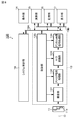
- FIG. 1 is a system configuration diagram schematically illustrating a configuration of an imaging system according to the first embodiment of the present disclosure.
- FIG. 2 is a schematic configuration diagram illustrating an example of a configuration of an imaging unit and a phase difference detection pixel.
- FIG. 3 is a diagram conceptually showing the exit pupil division direction and the exit pupil area of the imaging optical system.
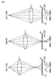
- FIG. 4 is a principle diagram of the focus degree detection for detecting the focus degree using the phase difference detection pixels.
- FIG. 5 illustrates a detection unit that detects a phase difference detection pixel in a focused state, a first map generation unit that generates a two-dimensional focus degree map of a subject, and a second map generation unit that generates a depth map.
- FIG. 3 is a functional block diagram of a calculation unit having each function.
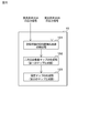
- FIG. 6 is a diagram illustrating a specific example of generating a two-dimensional focus degree map and a depth map in the imaging system according to the first embodiment.
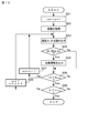
- FIG. 7 is a flowchart illustrating an example of a process of acquiring focusing information of a phase difference detection pixel in the imaging system according to the first embodiment.
- FIG. 8 is a system configuration diagram illustrating an outline of a configuration of an imaging system according to the second embodiment of the present disclosure.
- FIG. 9 is a diagram illustrating a specific example of generating a two-dimensional focus degree map and a depth map in the imaging system according to the second embodiment.
- FIG. 10 is a flowchart illustrating an example of a process of acquiring focusing information of a phase difference detection pixel in the imaging system according to the second embodiment.
- FIG. 11 is a flowchart illustrating another example of the process of acquiring the focus information of the phase difference detection pixels in the imaging system according to the second embodiment.
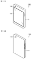
- FIG. 12A is an external view as viewed from the front side of a smartphone according to a specific example of the electronic device of the present disclosure
- FIG. 12B is an external view as viewed from the back side.
- a two-dimensional array is used to store position information of phase difference detection pixels detected for each of a plurality of images captured at different focal distances.
- a map generation unit (first map generation unit) for generating a two-dimensional in-focus degree map of the subject.
- the phase difference detection pixel may be configured to include a pair of light receiving elements. Then, the pair of light receiving elements are arranged side by side in a single pixel in a first direction, a second direction orthogonal to the first direction, or both directions of the first direction and the second direction. Configuration.
- a single imaging capable of adjusting the position of the imaging optical system in the optical axis direction is provided. It is possible to have a configuration in which a lens is provided and a plurality of images taken at different in-focus distances are obtained by performing a plurality of shootings at different positions of a single imaging lens.
- the focus detection device, the depth map generation device, and the electronic device of the present disclosure including the above-described preferred configuration include, in the electronic apparatus, an imaging optical system, including a plurality of imaging lenses having different focal positions, It is possible to obtain a plurality of images taken at different in-focus distances by a single photographing with a plurality of imaging lenses.
- FIG. 1 is a system configuration diagram schematically illustrating a configuration of an imaging system according to the first embodiment of the present disclosure.
- the imaging system 10A according to the first embodiment has a function of focus degree detection and a function of generating a depth map based on the focus degree, in addition to a normal photographing (standard photographing) function.
- the imaging system 10A includes an imaging optical system 11, a lens / aperture drive unit 12, an imaging device 13, an operation unit 14, an operation unit 15, a storage unit 16, a display unit 17, and a system control unit 18.
- System configuration In this system configuration, the imaging device 13, the operation unit 15, the storage unit 16, the display unit 17, and the system control unit 18 are connected to each other via a control bus line 19A.
- the imaging device 13, the operation unit 15, the storage unit 16, and the display unit 17 are connected to each other via a data bus line 19B.
- the imaging optical system 11 has an imaging lens 111 and an aperture 112, takes in image light from a subject (light of an image incident from the subject), and forms an image on an imaging surface of the imaging device 13.
- the position of the imaging lens 111 in the direction of the optical axis O can be adjusted by driving the lens / aperture drive unit 12. That is, the imaging system 10A according to the first embodiment has a configuration of a so-called monocular system having the imaging lens 111 capable of adjusting the position in the optical axis direction.
- the imaging system 10 ⁇ / b> A detects the degree of focus, and in the mode of the accompanying depth map generation, by the drive of the lens / aperture drive unit 12 under the control of the system control unit 18.
- a plurality of photographing positions can be set as positions of the imaging lens 111 in the optical axis direction. Then, a plurality of images taken at different in-focus distances can be obtained by a plurality of shootings at different positions of the imaging lens 111.
- the imaging device 13 includes an imaging unit 131, an analog signal processing unit 132, an A (analog) / D (digital) conversion unit 133, a digital image signal processing unit 134, and a control unit 135.
- the imaging unit 131 has a configuration in which phase difference detection pixels for detecting a phase difference between a pair of images based on image light from a subject are arranged in a two-dimensional array. More specifically, as shown in FIG. 2, the imaging unit 131 includes a pixel array unit 1311 in which the phase difference detection pixels 20 are arranged in a two-dimensional array, and each pixel of the pixel array unit 1311 (the phase difference detection pixel 20) comprises a row selection unit 1312 for selectively scanning each pixel row and a CMOS sensor having a column selection unit 1313 for selectively scanning each pixel in each pixel column.
- the imaging unit 131 is not limited to the CMOS sensor, and may be configured by a CCD sensor.
- the phase difference detection pixel 20 includes a first image based on the first light beam that has passed through the first pupil region included in the exit pupil of the imaging optical system 11 and a second image included in the exit pupil of the imaging optical system 11. And a second image based on the second light flux passing through the pupil region. Then, the degree of focus of the imaging optical system 11 can be detected from the luminance difference between the pair of images, that is, the luminance difference between the first image and the second image. Details of the focus degree detection (focus detection) will be described later.
- the analog signal processing unit 132 performs, for example, signal processing such as sample and hold on a pixel signal output from each pixel (the phase difference detection pixel 20) of the pixel array unit 1311 for each pixel column.
- the A / D converter 133 includes a set of a plurality of analog-to-digital converters provided corresponding to the pixel columns of the pixel array unit 1311, and converts an analog pixel signal output from the analog signal processing unit 132 into a digital signal. Convert to As the analog-to-digital converter of the A / D converter 133, a well-known analog-to-digital converter can be used. Examples of the well-known analog-digital converter include a single-slope analog-digital converter, a successive approximation analog-digital converter, and a delta-sigma ( ⁇ ) analog-digital converter. However, the analog-digital converter is not limited to these.
- the digital image signal processing unit 134 reads the digital pixel signal A / D converted by the A / D conversion unit 133 for each pixel column, performs various signal processing such as amplification processing and arithmetic processing, for example, and performs the present imaging apparatus. 13 to the data bus line 19B.
- the control unit 135 generates various timing signals, clock signals, control signals, and the like under the control of the system control unit 18, and based on the generated signals, the row selection unit 1312 of the imaging unit 131 and the analog signal processing.
- the drive control of the section 132, the A / D conversion section 133, the digital image signal processing section 134, and the like is performed.
- the operation unit 14 issues operation commands to the system control unit 18 for various functions of the imaging device 13 under the operation of the user.
- the calculation unit 15 performs calculation processing for general camera processing, for example, white balance processing, demosaic processing, gamma correction processing, and the like.
- the storage unit 16 is used for storing data as needed in the course of the arithmetic processing by the arithmetic unit 15.
- the display unit 17 includes a panel-type display device such as a liquid crystal display device or an organic EL display device, and displays a moving image or a still image captured by the imaging device 13.
- the system control unit 18 is configured by, for example, a microcomputer, and controls the lens / aperture drive unit 12 and the imaging device 13 based on an operation command from the operation unit 14 by a user, and further, via a control bus line 19A.
- the control unit 15 controls the calculation unit 15, the storage unit 16, and the display unit 17.
- an image plane phase difference AF is known as one of AF (autofocus) methods for automatically adjusting the focus of a camera.
- the phase difference detection pixel 20 is used to realize the image plane phase difference AF.
- the degree of focus (focus) of the imaging optical system 11 can be detected as described later.
- the phase difference detection pixel 20 has a pair of light receiving elements (for example, photodiodes) 20A and 20B provided in, for example, a single pixel.
- FIG. 3 conceptually shows the dividing direction of the ranging pupil and the area of the ranging pupil of the phase difference detection pixel 20.
- FIG. 3 is a diagram of the imaging system (camera) viewed obliquely from the front.
- the ranging pupil of the phase difference detection pixel 20 is a division in the first direction (the row direction / left / right direction), and each ranging pupil is one of the left and right divided regions of the exit pupil of the imaging optical system 11. It is large enough to cover.
- the phase difference detection pixel 20 includes an on-chip micro lens 21 on the light receiving surface side (the imaging optical system 11 side) of the pair of light receiving elements 20A and 20B.
- the exit pupil of the imaging optical system 11 and the pair of light receiving elements 20A and 20B are placed in a conjugate relationship by the on-chip microlens 21 in order to efficiently use the imaging light flux from the imaging optical system 11.
- the phase difference detection pixel 20 is provided with a pupil division function.
- phase difference detection pixel 20 a light beam passing through the right half of the imaging optical system 11 is guided to one light receiving element 20A, and a light beam passing through the left half of the imaging optical system 11 is guided to the other light receiving element 20B. Be guided. Then, an image captured by the plurality of light receiving elements 20A is referred to as a first image A, an image captured by the plurality of light receiving elements 20B is referred to as a second image B, and an overlap between the first image A and the second image B is determined. By detecting the degree, the degree of focus of the imaging optical system 11 can be detected. A part of the focus degree detection function may be used also as the auto focus function.
- the pair of light receiving elements 20A and 20B of the phase difference detection pixel 20 are arranged side by side in the first direction (row direction / left / right direction).
- the pair of light receiving elements 20A and 20B may be arranged side by side in a second direction (column direction / up / down direction) orthogonal to the first direction, or in the first direction and the second direction. May be arranged side by side in both directions.
- the arrangement of the pair of light receiving elements 20A and 20B is not limited to the arrangement within a single pixel, and may be configured such that half of the pixels are arranged over a plurality of masked pixels.
- FIG. 4 shows a principle diagram of the focus degree detection for detecting the focus degree using the phase difference detection pixel 20.
- FIG. 4 shows a focusing state, a front focus state, and a rear focus state in the imaging optical system 11.
- the “focused state” refers to a state in which the focus is on the imaging surface of the imaging unit 131
- the “front focus state” refers to a state in which the focus position is on the front side of the imaging surface of the imaging unit 131. (The imaging optical system 11 side)
- the “back focus state” refers to a state in which the focus position is shifted rearward from the imaging surface of the imaging unit 131.
- the first light flux that has passed through the first pupil region included in the exit pupil of the imaging optical system 11 and the second light beam that has passed through the second pupil region included in the exit pupil of the imaging optical system 11 The light beam overlaps most, and the luminance of the image based on the first light beam and the second light beam acquired by the pair of light receiving elements 20A and 20B of the phase difference detection pixel 20 becomes maximum.
- the center of gravity of the first pupil region matches the center of gravity of the second pupil region, and the brightness of the first image A acquired by one light receiving element 20A and the other light receiving element 20B And the brightness of the second image B acquired by the above becomes equal.
- “equal” means not only the case where the luminance of the first image A and the luminance of the second image B are exactly equal but also the case where they are substantially equal. The existence of various manufacturing variations is acceptable.
- the state where the luminance difference between the first image A and the second image B is ideally zero is the in-focus state, but here, the luminance of the first image A and the second image B is A state where the difference is equal to or less than a predetermined value close to zero is defined as an in-focus state.
- the center of gravity of the first pupil region and the center of gravity of the second pupil region do not match, and are located at different positions. Then, in the front focus state, with respect to the optical center O, the first image A acquired by the plurality of light receiving elements 20A moves to the left, and the second image B acquired by the plurality of light receiving elements 20B moves to the right. . In the back focus state, the second image B acquired by the plurality of light receiving elements 20B moves away from the optical center O to the left, and the first image A acquired by the plurality of light receiving elements 20A moves away to the right. . In such a state, a difference occurs between the output of the light receiving element 20A and the output of the light receiving element 20B.
- the detection process of the degree of focus (focus) of the imaging optical system 11 based on the output signals of the pair of light receiving elements 20A and 20B of the phase difference detection pixel 20 is executed by, for example, the calculation unit 15 (see FIG. 1). That is, the calculating unit 15 detects, for each of a plurality of images captured at different in-focus distances, a phase difference detection pixel in which the luminance difference between the first image A and the second image B is equal to or smaller than a predetermined value.
- the calculating unit 15 detects, for each of a plurality of images captured at different in-focus distances, a phase difference detection pixel in which the luminance difference between the first image A and the second image B is equal to or smaller than a predetermined value.
- the position of the imaging lens 111 is adjusted in the optical axis direction, and the position of the imaging lens 111 is changed at a different position, that is, the focus is adjusted. Shooting at different distances to obtain a plurality of images.
- the arithmetic unit 15 controls the luminance difference
- the calculation unit 15 provided outside the imaging device 13 has a function of a detection unit that detects a phase difference detection pixel in a focused state, but the detection unit is provided by a CMOS sensor or a CCD sensor.
- the imaging device 13 may be configured to be incorporated as a part of a functional unit.
- the calculation unit 15 has a function of detecting a phase difference detection pixel in a focused state, and also detects a phase difference in a focused state, which is detected for each of a plurality of images taken at different in-focus distances. It has a function of a first map generation unit that maps pixel position information into a two-dimensional array and generates a two-dimensional focus degree map of a subject. In the calculation unit 15, the function of the first map generation unit is executed under the control of the system control unit 18.
- the depth information (depth value) of the three-dimensional shape of the subject can be estimated from the focusing distance of each of a plurality of images.
- the calculation unit 15 further includes, in addition to the function of the detection unit and the function of the first map generation unit, depth information of the subject estimated from the in-focus distance of each of the plurality of images, and a two-dimensional focus degree It has a function of a second map generation unit that generates a depth map based on the map.
- the function of the second map generation unit is executed under the control of the system control unit 18.
- FIG. 5 shows a functional block diagram of the operation unit 15.
- the calculation unit 15 includes a detection unit 151 that detects a phase difference detection pixel in a focused state, a first map generation unit 152 that generates a two-dimensional focus degree map of a subject, and a depth map.
- the position P 1 farthest from the imaging surface of the imaging unit 131, and the position P 2 , the position P 3 , the position closest to the imaging surface as approaching the imaging surface. shall be set are four in close P 4.
- the distance between the focus when taken at the position P 1 matches and f 1
- the distance the focus when taken at the position P 2 matches the f 2
- the distance the focus when taken at the position P 3 fit f 3 and then, the in focus distance when taken with the position P 4 to f 4.
- the position of the phase difference detection pixel 20 that is in focus is: It differs according to the three-dimensional shape of the subject.
- the pixel array of the pixel array unit 1311 is 4 pixels in the horizontal direction ⁇ 4 pixels in the vertical direction is taken as an example, and generation of a two-dimensional focus degree map and a depth map will be described with reference to FIG. This will be described with reference to FIG.
- the first row and first column and four rows of two points of the position of the fourth column phase difference detection pixel 20 is in focus It shall be.
- a distance f 2 that in focus corresponding to the three-dimensional shape of the object, second row and first column, first row and second column, fourth row third column and the fourth position of the third row fourth column It is assumed that the phase difference detection pixels 20 at the location are in focus.
- phase difference detection pixels 20 at the position of the second row and the fourth column are in focus.
- a distance f 4 which in focus corresponding to the three-dimensional shape of the object, 4 row and first column, third row second column, second row third column and the fourth position of the first row 4 column It is assumed that the phase difference detection pixels 20 at the location are in focus.
- the position information of the phase difference detection pixel 20 detected for each of the four images captured at different in-focus distances f 1 to f 4 is obtained by the function of the first map generation unit of the calculation unit 15.
- a two-dimensional focus degree map of the subject can be generated for each image at the focused distances f 1 to f 4 .
- the depth information D 1 to D 4 of the three-dimensional shape of the subject estimated from the in-focus distances f 1 to f 4 and the two-dimensional A depth map can be generated based on the focus degree map.
- the above-described specific example is an example of an algorithm for generating a depth map, and is not limited thereto.
- An existing generation algorithm may be used.
- the calculation unit 15 in the imaging system 10A detects the degree of focus using the phase difference detection pixel 20, and obtains the depth map of the three-dimensional shape of the subject (for example, the face to be recognized). Is generated, it is only necessary to detect a phase difference detection pixel in which the luminance difference between the first image A and the second image B is equal to or less than a predetermined value.
- the arithmetic unit 15 simply performs focusing on each of a plurality of images captured at different in-focus distances without acquiring depth information based on which a depth map is generated from the image data by arithmetic processing.
- the depth map can be generated only by detecting the phase difference detection pixels in the state. Therefore, acquisition of depth information and generation of a depth map can be realized in a short processing time with a small circuit scale.
- FIG. 7 is a flowchart illustrating an example of a process of acquiring focusing information of the phase difference detection pixel 20 in the imaging system 10A according to the first embodiment.
- the position of the imaging lens 111 in the optical axis direction in the above case, four types of positions P 1 to P 4 can be set.
- the position numbers N of the positions P 1 to P 4 are set to 1 to 4.
- the coordinates of the phase difference detection pixel 20 in the focused state be PD (m, n).
- the process of acquiring the focus information of the phase difference detection pixel 20 in the focused state is a part of the process for generating the two-dimensional focus degree map. This is a process executed by the unit 15.
- the system controller 18 when taken at the position P 1, reads out the first image A and a second image B captured by the phase difference detection pixel 20 coordinate PD (1, 1) (Step S14 Then, it is determined whether or not the luminance difference
- the system control unit 18 determines that the phase difference detection pixel 20 is in the focused state, and For example, a focus degree based on the luminance difference
- the focus degree output as the focus information is a signal indicating the closeness of the luminance between the first image and the second image. If the luminance difference
- the system control unit 18 increments the position number N and sets the initial value 1 as the coordinate position m, n in the horizontal and vertical directions. Is set (step S22), and then the imaging lens 11 is driven by a predetermined amount to the next position (step S23). Thereafter, the process returns to step S13. Then, the system control unit 18 repeatedly executes the processing from step S13 to step S21 until the position number N exceeds the maximum value Nmax .
- the focus information of the phase difference detection pixel 20 in focus which is used for generating the two-dimensional focus degree map, is focused.
- the degree can be obtained, and the position of the phase difference detection pixel 20 in the image (pixel array unit) can be specified.
- a degree map can be generated, and a depth map can be generated based on the two-dimensional focus degree map.
- the focus information of the phase difference detection pixel 20 in the focused state the focus degree based on the luminance difference
- position information may be output instead of the degree of focus.
- the focus information of the phase difference detection pixel 20 in a focused state may be output as it is, or may be compressed and output.
- FIG. 8 is a system configuration diagram illustrating an outline of a configuration of an imaging system according to the second embodiment of the present disclosure. Similar to the imaging system 10A according to the first embodiment, the imaging system 10B according to the second embodiment has a function of normal imaging (standard imaging), a degree of focus detection, and generation of a depth map based thereon. Has the function of
- An imaging system 10B has a system configuration including an imaging optical system 11, an imaging device 13, an operation unit 14, a calculation unit 15, a storage unit 16, a display unit 17, and a system control unit 18. .
- the imaging device 13, the operation unit 15, the storage unit 16, the display unit 17, and the system control unit 18 are connected to each other via a control bus line 19A.
- the imaging device 13, the operation unit 15, the storage unit 16, and the display unit 17 are connected to each other via a data bus line 19B.
- the imaging optical system 11 has a configuration of a so-called compound eye system having a plurality of imaging lenses 111 (multi-lens lenses) arranged around the optical axis O and having different focal positions (focus depths).
- the compound eye system can also be called a multi-eye system.
- the imaging optical system 11 of the compound-eye system configuration multi-view system configuration
- the configurations and functions of the imaging device 13, the operation unit 14, the calculation unit 15, the storage unit 16, the display unit 17, and the system control unit 18 are basically the same as the corresponding components in the imaging system 10A according to the first embodiment. Is the same as The principle of focus degree detection based on the first image A and the second image B acquired by the phase difference detection pixels 20 arranged in the two-dimensional array in the imaging unit 131 of the imaging device 13 is also described. This is as described in the first embodiment.
- the imaging system 10B according to the second embodiment since it is a compound eye system configuration having a plurality of imaging lenses 111 having different focal positions, a plurality of imaging lenses at different focal lengths can be obtained by one shooting. One image can be obtained. Accordingly, the imaging system 10B according to the second embodiment is more advantageous than the imaging system 10A according to the first embodiment with respect to the time required to acquire a plurality of images captured at different in-focus distances. In the case of the imaging system 10B according to the second embodiment, since there is no mechanism for moving the imaging lens 111 in the direction of the optical axis O, the direction of the optical axis O is smaller than that of the imaging system 10A according to the first embodiment. Can be reduced in size.
- FIG. 9 shows a specific example of generating a two-dimensional focus degree map and a depth map in the imaging system 10B according to the second embodiment.
- the signals from the two-dimensional array-shaped phase difference detection pixels 20 are sequentially AD-converted, the brightness of the paired first image A and the brightness of the second image B are compared, and output as a focus degree indicating the closeness of brightness. I do.
- mapping the position information of the in-focus phase difference detection pixels 20 in a two-dimensional array a two-dimensional focus degree map of the subject is generated for each image at the focused distances f 1 to f 4. be able to.
- a depth map can be generated based on the depth information D 1 to D 4 of the three-dimensional shape of the subject estimated from the focusing distances f 1 to f 4 and the two-dimensional focus degree map. .
- FIG. 10 is a flowchart illustrating an example of a process of acquiring focusing information of the phase difference detection pixel 20 in the imaging system 10B according to the second embodiment.
- the number of images captured and acquired at different in-focus distances is set to four, and corresponding to the movement positions P 1 to P 4 of the imaging lens 111, The distances at which the respective focuses are set are f 1 to f 4 .
- the imaging system 10B according to the second embodiment in the imaging optical system 11, four imaging lenses 111 are arranged around the optical axis O, and the focus of each of the four imaging lenses 111 is The matching distance is defined as f 1 to f 4 .
- the process of acquiring the focus information of the phase difference detection pixel 20 is a part of the process for generating the two-dimensional focus degree map. Therefore, similarly to the case of the imaging system 10A according to the first embodiment, the acquisition process of the focusing information of the phase difference detection pixels 20 is executed in the calculation unit 15 under the control of the system control unit 18.
- a two-dimensional map is read and synthesized for each of different areas at different distances where the compound eye is in focus.
- the system control unit 18 sets the coordinate position m in the horizontal direction (row direction) and the coordinate position n in the vertical direction (column direction) to 1 (step S31), and then acquires four captured images (step S31). (Step S32) Then, the first image A and the second image B captured by the phase difference detection pixels 20 of the obtained image are read out (Step S33).
- the system control unit 18 determines whether the luminance difference
- focusing is performed as focus information of the phase difference detection pixel 20 in a focused state used for generating a two-dimensional focus degree map.
- the degree can be obtained, and the position of the phase difference detection pixel 20 in the image (pixel array unit) can be specified.
- a depth map can be generated based on the two-dimensional focus degree map.
- FIG. 11 shows another example of the process of acquiring the focusing information of the phase difference detection pixel 20 in the imaging system 10B according to the second embodiment.
- the image numbers M of the images taken at the in-focus distances f 1 to f 4 are set to 1 to 4.
- the two-dimensional map is read and synthesized for each of different areas at different distances where the compound eye is in focus.
- Step S41 the system control unit 18 increments the image number M (Step S41), and then returns to Step S33, and returns from Step S34 to Step S34.
- the processing up to S41 is repeatedly executed until the image number M exceeds the maximum value Mmax . If the image number M exceeds the maximum value Mmax (Yes in S40), the system control unit 18 ends a series of processing for acquiring the focusing information of the phase difference detection pixel 20.
- the focus degree is acquired as the focus information of the phase difference detection pixel 20 in the focused state, and the position information of the phase difference detection pixel 20 is obtained.
- the focus information of the phase difference detection pixel 20 in a focused state the focus degree based on the luminance difference
- ⁇ Modification> As described above, the technology of the present disclosure has been described based on the preferred embodiments, but the technology of the present disclosure is not limited to the embodiments.
- the configuration and structure of the imaging system described in each of the above embodiments are examples, and can be changed as appropriate.
- a depth sensing system using a multi-lens lens having a different focusing depth and a normal monocular system for imaging are hybridized.
- a hybrid system can also be used.
- the resolution of pixel readout and the resolution of focus determination may be changed, and the control of the resolution in the depth (depth) direction may be performed by controlling the position of the imaging lens in the optical axis direction.
- imaging, detection, and reading may be performed in consideration of the response speed of the position control of the imaging lens.
- the imaging system 10A according to the first embodiment or the imaging system 10B according to the second embodiment including the focus detection device and the depth map generation device according to the present disclosure described above includes various electronic devices having a camera function (imaging function). It can be used as an imaging unit (imaging device) mounted on a device. Examples of the electronic device having the camera function include a mobile device such as a smartphone, a digital camera, a tablet, and a personal computer. However, electronic devices that can use the imaging system 10A according to the first embodiment or the imaging system 10B according to the second embodiment are not limited to mobile devices.
- FIG. 12A shows an external view of a smartphone according to a specific example of the electronic device of the present disclosure, as viewed from the front side
- FIG. 12B shows an external view as viewed from the back side.
- the smartphone 100 includes the display unit 120 on the front side of the housing 110.
- the smartphone 100 includes imaging units (cameras) 130 and 140 in an upper part on the front side and an upper part on the back side of the housing 110.
- An imaging system 10B according to the second embodiment can be used. That is, the smartphone 100 according to this specific example is manufactured by using the imaging system 10A according to the first embodiment or the imaging system 10B according to the second embodiment as the imaging units 130 and 140.
- the smartphone 100 includes the imaging system 10A according to the first embodiment or the imaging system 10B according to the second embodiment as the imaging units 130 and 140, and detects the degree of focus of the present disclosure described above.
- the functions of the apparatus and the depth map generation apparatus it is possible to have a function of recognizing a three-dimensional shape of a subject, for example, a face recognition function.
- Focus detection device [A-1] an imaging optical system that captures image light from a subject, Phase difference detection pixels for obtaining a first image and a second image based on a light beam respectively passing through the first pupil region and the second pupil region included in the exit pupil of the imaging optical system are arranged in a two-dimensional array.
- An imaging unit comprising: A detection unit that detects a phase difference detection pixel in which the luminance difference between the first image and the second image is equal to or less than a predetermined value for each of a plurality of images captured at different focal distances; Focus detection device.
- [A-2] The position information of the phase difference detection pixels detected by the detection unit is mapped in a two-dimensional array for each of a plurality of images photographed at different in-focus distances, and a two-dimensional focus degree map of the subject is obtained. Having a map generation unit for generating, The focus degree detection device according to the above [A-1].
- the phase difference detection pixel includes a pair of light receiving elements.
- [A-4] The pair of light receiving elements are arranged in a single pixel in the first direction, the second direction orthogonal to the first direction, or both the first direction and the second direction. Are located in the The focus degree detection device according to the above [A-3].
- the imaging optical system has a single imaging lens whose position can be adjusted in the direction of the optical axis. Obtain multiple images taken with The focus detection device according to any one of [A-1] to [A-4].
- the imaging optical system has a plurality of imaging lenses with different focal positions, and obtains a plurality of images taken at different in-focus distances by one shooting with the plurality of imaging lenses.
- the focus detection device according to any one of [A-1] to [A-4].
- Imaging unit A detection unit that detects a phase difference detection pixel in which a luminance difference between the first image and the second image is equal to or less than a predetermined value for each of a plurality of images captured at different focal distances; A first method of mapping the position information of the phase difference detection pixels detected by the detection unit into a two-dimensional array for each of a plurality of images captured at different in-focus distances to generate a two-dimensional focus degree map of the subject.
- the phase difference detection pixel includes a pair of light receiving elements.
- a pair of light receiving elements are arranged in a single pixel in a first direction, a second direction orthogonal to the first direction, or both directions of the first direction and the second direction. Are located in the The depth map generation device according to the above [B-2].
- the imaging optical system has a single imaging lens whose position can be adjusted in the optical axis direction, and different distances at which the single imaging lens focuses on a plurality of times at different positions. Obtain multiple images taken with The depth map generation device according to any of [B-1] to [B-3].
- the imaging optical system has a plurality of imaging lenses having different focal positions, and obtains a plurality of images taken at different in-focus distances by a single shooting with the plurality of imaging lenses.
- the depth map generation device according to any of [B-1] to [B-3].
- C-1 an imaging optical system that captures image light from a subject, Phase difference detection pixels for obtaining a first image and a second image based on a light beam respectively passing through the first pupil region and the second pupil region included in the exit pupil of the imaging optical system are arranged in a two-dimensional array.
- Imaging unit A detection unit that detects a phase difference detection pixel in which a luminance difference between the first image and the second image is equal to or less than a predetermined value for each of a plurality of images captured at different focal distances; A first method of mapping the position information of the phase difference detection pixels detected by the detection unit into a two-dimensional array for each of a plurality of images captured at different in-focus distances to generate a two-dimensional focus degree map of the subject.
- An electronic device equipped with a depth map generator.
- the phase difference detection pixel includes a pair of light receiving elements.
- the pair of light receiving elements are arranged in a single pixel in the first direction, the second direction orthogonal to the first direction, or both directions of the first direction and the second direction. Are located in the The electronic device according to the above [C-2].
- the imaging optical system has a single imaging lens whose position in the direction of the optical axis can be adjusted. Obtain multiple images taken with The electronic device according to any one of the above [C-1] to [C-3].
- the imaging optical system has a plurality of imaging lenses having different focal positions, and obtains a plurality of images photographed at different in-focus distances by one photographing with the plurality of imaging lenses.
- the electronic device according to any one of the above [C-1] to [C-3].
- 10A imaging system according to the first embodiment
- 10B imaging system according to the second embodiment
- 11 imaging optical system
- 12 lens / aperture drive unit
- 14 operation unit, 15 ... calculation unit
- 16 ... storage unit
- 17 ... display unit
- 18 ... system control unit
- 19A ... control bus line
- 19B data Bus line
- 20 phase difference detection pixel
- 20A, 20B pair of light receiving elements
- 21 on-chip micro lens
Landscapes
- Physics & Mathematics (AREA)
- Engineering & Computer Science (AREA)
- General Physics & Mathematics (AREA)
- Multimedia (AREA)
- Signal Processing (AREA)
- Theoretical Computer Science (AREA)
- Optics & Photonics (AREA)
- Computing Systems (AREA)
- Electromagnetism (AREA)
- Radar, Positioning & Navigation (AREA)
- Remote Sensing (AREA)
- Studio Devices (AREA)
- Focusing (AREA)
- Automatic Focus Adjustment (AREA)
Abstract
本開示の合焦度検出装置は、被写体の像光を取り込む結像光学系、結像光学系が有する第1の瞳領域及び第2の瞳領域をそれぞれ通過した光束に基づく第1の画像及び第2の画像を得る位相差検出画素が二次元アレイ状に配置されて成る画素アレイ部、並びに、焦点の合う異なる距離で撮影した複数枚の画像毎に、第1の画像及び第2の画像の輝度差が所定値以下の位相差検出画素を検出する検出部を備える。
Description
本開示は、合焦度検出装置、深度マップ生成装置、及び、電子機器に関する。
近年、スマートフォン等の電子機器において、三次元形状を計測する技術が用いられている。三次元形状の計測方法としては、能動計測法及び受能計測法が知られている。レーザ計測や、TOF(Time Of Flight:飛行時間)等の能動計測法は、一般的に、受能計測法に比べて使用装置が大型化し、高価格となる傾向にある。
受能計測法に属する三次元形状の計測方法として、焦点を変化させて撮影した計測対象の物体の画像群(即ち、多焦点画像群)を用いて物体表面の各点までの深度の値を推定する、一般的に、SFF/SFD(Shape From Focus/Defocus)法と呼ばれる手法がある。このSFF/SFD法の一つとして、従来、位相差検出画素の位置情報を使用して、深度マップを生成する技術が提案されている(例えば、特許文献1参照)。
この従来技術では、位相差検出画素の位置情報を使用して、画像データから、第1の位相差検出画素データ及び第2の位相差検出画素データを抽出し、第1のウィンドウ及び第2のウィンドウの移動に基づいて、第1の位相差検出画素データ及び第2の位相差検出画素データから第1の位相グラフ及び第2の位相グラフを計算する演算処理が行われる。そして、第1の位相グラフ及び第2の位相グラフを使用して、位相差のずれを計算する演算処理が行われ、この演算で求めた位相差のずれを基に深度マップの生成が行われる。
上記の特許文献1に記載の従来技術では、位相差検出画素の位置情報を使用して、画像データから演算処理によって、深度マップの生成の基となる深度情報(depth値)を取得することになるため、即応性に乏しく、また、演算処理のための回路規模が大きくなってしまう。
そこで、本開示は、小さな回路規模にて、深度情報の取得を短い処理時間で実現できる合焦度検出装置、深度マップの生成を短い処理時間で実現できる深度マップ生成装置、及び、当該深度マップ生成装置を搭載する電子機器を提供することを目的とする。
上記の目的を達成するための本開示の合焦度検出装置は、
被写体からの像光を取り込む結像光学系、
結像光学系の射出瞳に含まれる第1の瞳領域及び第2の瞳領域をそれぞれ通過した光束に基づく第1の画像及び第2の画像を得る位相差検出画素が二次元アレイ状に配置されて成る撮像部、並びに、
焦点の合う異なる距離で撮影した複数枚の画像毎に、第1の画像及び第2の画像の輝度差が所定値以下の位相差検出画素を検出する検出部を備える、
ことを特徴とする。
被写体からの像光を取り込む結像光学系、
結像光学系の射出瞳に含まれる第1の瞳領域及び第2の瞳領域をそれぞれ通過した光束に基づく第1の画像及び第2の画像を得る位相差検出画素が二次元アレイ状に配置されて成る撮像部、並びに、
焦点の合う異なる距離で撮影した複数枚の画像毎に、第1の画像及び第2の画像の輝度差が所定値以下の位相差検出画素を検出する検出部を備える、
ことを特徴とする。
また、上記の目的を達成するための本開示の深度マップ生成装置は、
被写体からの像光を取り込む結像光学系、
結像光学系の射出瞳に含まれる第1の瞳領域及び第2の瞳領域をそれぞれ通過した光束に基づく第1の画像及び第2の画像を得る位相差検出画素が二次元アレイ状に配置されて成る撮像部、
焦点の合う異なる距離で撮影した複数枚の画像毎に、第1の画像及び第2の画像の輝度差が所定値以下の位相差検出画素を検出する検出部、
焦点の合う異なる距離で撮影した複数枚の画像毎に、検出部が検出した位相差検出画素の位置情報を二次元アレイ状にマッピングし、被写体の二次元合焦度マップを生成する第1のマップ生成部、並びに、
複数枚の画像毎の焦点が合う距離から推定される被写体の深度情報、及び、二次元合焦度マップを基に深度マップを生成する第2のマップ生成部を備える、
ことを特徴とする。
被写体からの像光を取り込む結像光学系、
結像光学系の射出瞳に含まれる第1の瞳領域及び第2の瞳領域をそれぞれ通過した光束に基づく第1の画像及び第2の画像を得る位相差検出画素が二次元アレイ状に配置されて成る撮像部、
焦点の合う異なる距離で撮影した複数枚の画像毎に、第1の画像及び第2の画像の輝度差が所定値以下の位相差検出画素を検出する検出部、
焦点の合う異なる距離で撮影した複数枚の画像毎に、検出部が検出した位相差検出画素の位置情報を二次元アレイ状にマッピングし、被写体の二次元合焦度マップを生成する第1のマップ生成部、並びに、
複数枚の画像毎の焦点が合う距離から推定される被写体の深度情報、及び、二次元合焦度マップを基に深度マップを生成する第2のマップ生成部を備える、
ことを特徴とする。
また、上記の目的を達成するための本開示の電子機器は、上記の構成の深度マップ生成装置を搭載することを特徴とする。
以下、本開示の技術を実施するための形態(以下、「実施形態」と記述する)について図面を用いて詳細に説明する。本開示の技術は実施形態に限定されるものではない。以下の説明において、同一要素又は同一機能を有する要素には同一符号を用いることとし、重複する説明は省略する。尚、説明は以下の順序で行う。
1.本開示の合焦度検出装置、深度マップ生成装置、及び、電子機器、全般に関する説明
2.第1実施形態(単眼システム構成の例)
2-1.システム構成
2-2.合焦度検出の原理
2-3.二次元合焦度マップ及び深度マップの生成
2-4.合焦状態にある位相差検出画素の合焦情報の取得
3.第2実施形態(複眼システム構成の例)
3-1.システム構成
3-2.二次元合焦度マップ及び深度マップの生成
3-3.合焦状態にある位相差検出画素の合焦情報の取得
4.変形例
5.本開示の電子機器
6.本開示がとることができる構成
1.本開示の合焦度検出装置、深度マップ生成装置、及び、電子機器、全般に関する説明
2.第1実施形態(単眼システム構成の例)
2-1.システム構成
2-2.合焦度検出の原理
2-3.二次元合焦度マップ及び深度マップの生成
2-4.合焦状態にある位相差検出画素の合焦情報の取得
3.第2実施形態(複眼システム構成の例)
3-1.システム構成
3-2.二次元合焦度マップ及び深度マップの生成
3-3.合焦状態にある位相差検出画素の合焦情報の取得
4.変形例
5.本開示の電子機器
6.本開示がとることができる構成
<本開示の合焦度検出装置、深度マップ生成装置、及び、電子機器、全般に関する説明>
本開示の合焦度検出装置、深度マップ生成装置、及び、電子機器にあっては、焦点の合う異なる距離で撮影した複数枚の画像毎に検出した位相差検出画素の位置情報を二次元アレイ状にマッピングし、被写体の二次元合焦度マップを生成するマップ生成部(第1のマップ生成部)を有する構成とすることができる。
本開示の合焦度検出装置、深度マップ生成装置、及び、電子機器にあっては、焦点の合う異なる距離で撮影した複数枚の画像毎に検出した位相差検出画素の位置情報を二次元アレイ状にマッピングし、被写体の二次元合焦度マップを生成するマップ生成部(第1のマップ生成部)を有する構成とすることができる。
上述した好ましい構成を含む本開示の合焦度検出装置、深度マップ生成装置、及び、電子機器にあっては、位相差検出画素について、一対の受光素子から成る構成とすることができる。そして、一対の受光素子について、単一の画素内に、第1の方向、第1の方向と直交する第2の方向、又は、第1の方向及び第2の方向の両方向において並んで配置されている構成とすることができる。
また、上述した好ましい構成を含む本開示の合焦度検出装置、深度マップ生成装置、及び、電子機器にあっては、結像光学系について、光軸方向における位置調整が可能な単一の撮像レンズを有し、単一の撮像レンズの異なる位置での複数回の撮影で、焦点の合う異なる距離で撮影した複数枚の画像を得る構成とすることができる。
あるいは又、上述した好ましい構成を含む本開示の合焦度検出装置、深度マップ生成装置、及び、電子機器にあっては、結像光学系について、焦点位置の異なる複数の撮像レンズを有し、複数の撮像レンズによる1回の撮影で、焦点の合う異なる距離で撮影した複数枚の画像を得る構成とすることができる。
<第1実施形態>
図1は、本開示の第1実施形態に係る撮像システムの構成の概略を示すシステム構成図である。第1実施形態に係る撮像システム10Aは、通常の撮影(標準の撮影)の機能の他に、合焦度検出、及び、それに基づく深度マップ生成の機能を持っている。
図1は、本開示の第1実施形態に係る撮像システムの構成の概略を示すシステム構成図である。第1実施形態に係る撮像システム10Aは、通常の撮影(標準の撮影)の機能の他に、合焦度検出、及び、それに基づく深度マップ生成の機能を持っている。
[システム構成]
第1実施形態に係る撮像システム10Aは、撮像光学系11、レンズ・絞り駆動部12、撮像装置13、操作部14、演算部15、記憶部16、表示部17、及び、システム制御部18を有するシステム構成となっている。このシステム構成において、撮像装置13、演算部15、記憶部16、表示部17、及び、システム制御部18は、制御バスライン19Aを介して互いに接続されている。また、撮像装置13、演算部15、記憶部16、及び、表示部17は、データバスライン19Bを介して互いに接続されている。
第1実施形態に係る撮像システム10Aは、撮像光学系11、レンズ・絞り駆動部12、撮像装置13、操作部14、演算部15、記憶部16、表示部17、及び、システム制御部18を有するシステム構成となっている。このシステム構成において、撮像装置13、演算部15、記憶部16、表示部17、及び、システム制御部18は、制御バスライン19Aを介して互いに接続されている。また、撮像装置13、演算部15、記憶部16、及び、表示部17は、データバスライン19Bを介して互いに接続されている。
撮像光学系11は、撮像レンズ111及び絞り112を有し、被写体からの像光(被写体から入射される像の光)を取り込み、撮像装置13の撮像面上に結像する。撮像レンズ111は、レンズ・絞り駆動部12による駆動によって、光軸Oの方向における位置が調整可能となっている。すなわち、第1実施形態に係る撮像システム10Aは、光軸方向における位置調整が可能な撮像レンズ111を有する、所謂、単眼システムの構成となっている。
単眼システム構成の第1実施形態に係る撮像システム10Aは、合焦度検出、及び、それに伴う深度マップ生成のモードでは、システム制御部18による制御の下に、レンズ・絞り駆動部12による駆動によって、撮像レンズ111の光軸方向における位置として、複数の撮影位置を設定することができる。そして、撮像レンズ111の異なる位置での複数回の撮影で、焦点の合う異なる距離で撮影した複数枚の画像を取得することができる。
撮像装置13は、撮像部131、アナログ信号処理部132、A(アナログ)/D(デジタル)変換部133、デジタル画像信号処理部134、及び、制御部135を有する構成となっている。
撮像部131は、被写体からの像光に基づく一対の像の位相差を検出するための位相差検出画素が二次元アレイ状に配置された構成となっている。より具体的には、図2に示すように、撮像部131は、位相差検出画素20が二次元アレイ状に配置されて成る画素アレイ部1311、画素アレイ部1311の各画素(位相差検出画素20)を画素行単位で選択走査する行選択部1312、及び、各画素を画素列単位で選択走査する列選択部1313を有するCMOSセンサから成る。但し、撮像部131については、CMOSセンサに限られるものではなく、CCDセンサから成る構成であってもよい。
位相差検出画素20は、撮像光学系11の射出瞳に含まれる第1の瞳領域を通過した第1の光束に基づく第1の画像と、撮像光学系11の射出瞳に含まれる第2の瞳領域を通過した第2の光束に基づく第2の画像とを取得する。そして、一対の画像の輝度差、即ち、第1の画像及び第2の画像の輝度差から、撮像光学系11の合焦度を検出することができる。合焦度検出(焦点検出)の詳細については後述する。
アナログ信号処理部132は、例えば、画素アレイ部1311の各画素(位相差検出画素20)から画素列毎に出力される画素信号に対して、サンプル&ホールドなどの信号処理を行う。
A/D変換部133は、画素アレイ部1311の画素列に対応して設けられた複数のアナログ-デジタル変換器の集合から成り、アナログ信号処理部132から出力されるアナログの画素信号をデジタル信号に変換する。A/D変換部133のアナログ-デジタル変換器としては、周知のアナログ-デジタル変換器を用いることができる。周知のアナログ-デジタル変換器として、シングルスロープ型アナログ-デジタル変換器、逐次比較型アナログ-デジタル変換器、又は、デルタ-シグマ型(ΔΣ型)アナログ-デジタル変換器を例示することができる。但し、アナログ-デジタル変換器は、これらに限定されるものではない。
デジタル画像信号処理部134は、A/D変換部133でA/D変換されたデジタル画素信号を画素列毎に読み出し、例えば、増幅処理や演算処理等の種々の信号処理を行い、本撮像装置13の撮像信号としてデータバスライン19Bに出力する。
制御部135は、システム制御部18による制御の下に、各種のタイミング信号、クロック信号、制御信号等を生成し、これら生成した信号を基に、撮像部131の行選択部1312、アナログ信号処理部132、A/D変換部133、及び、デジタル画像信号処理部134等の駆動制御を行う。
操作部14は、ユーザによる操作の下に、システム制御部18に対して、撮像装置13が持つ様々な機能について操作指令を発する。演算部15は、一般的なカメラ処理、例えば、ホワイトバランス処理、デモザイク処理、ガンマ補正処理などのための演算処理を行う。記憶部16は、演算部15での演算処理の過程で適宜データの格納に用いられる。表示部17は、液晶表示装置や有機EL表示装置などのパネル型表示装置から成り、撮像装置13で撮像された動画又は静止画を表示する。
システム制御部18は、例えばマイクロコンピュータによって構成され、操作部14からのユーザによる操作指令に基づいて、レンズ・絞り駆動部12の制御や撮像装置13の制御、更には、制御バスライン19Aを介しての、演算部15、記憶部16、及び、表示部17の制御を行う。
[合焦度検出の原理]
ここで、合焦度検出(焦点検出)の詳細について説明する。デジタルカメラ等の撮像システムにおいて、カメラの焦点(ピント)を自動的に合わせるAF(オートフォーカス)方式の一つとして像面位相差AFが知られている。そして、像面位相差AFを実現するために、位相差検出画素20が用いられる。また、位相差検出画素20を用いることで、後述するように、撮像光学系11の合焦度(焦点)を検出することができる。
ここで、合焦度検出(焦点検出)の詳細について説明する。デジタルカメラ等の撮像システムにおいて、カメラの焦点(ピント)を自動的に合わせるAF(オートフォーカス)方式の一つとして像面位相差AFが知られている。そして、像面位相差AFを実現するために、位相差検出画素20が用いられる。また、位相差検出画素20を用いることで、後述するように、撮像光学系11の合焦度(焦点)を検出することができる。
図2に示すように、位相差検出画素20は、例えば単一の画素内に設けられた一対の受光素子(例えば、フォトダイオード)20A,20Bを有する。位相差検出画素20の測距瞳の分割方向及び測距瞳面積を図3に概念的に示す。図3は、撮像システム(カメラ)を斜め前方から見た図である。位相差検出画素20の測距瞳は、第1の方向(行方向/左右方向)における分割であり、個々の測距瞳は、撮像光学系11の射出瞳を左右に分割した各々一方の領域を覆う大きさになっている。
図3に示すように、位相差検出画素20は、一対の受光素子20A,20Bの受光面側(撮像光学系11側)に、オンチップマイクロレンズ21を備えている。そして、撮像光学系11による撮像光束を効率良く利用するために、撮像光学系11の射出瞳と一対の受光素子20A,20Bとは、オンチップマイクロレンズ21によって共役の関係に置かれる。この構成により、位相差検出画素20には瞳分割機能が付与される。
位相差検出画素20において、一方の受光素子20Aには、撮像光学系11の右半分を通過した光束が導かれ、他方の受光素子20Bには、撮像光学系11の左半分を通過した光束が導かれる。そして、複数の受光素子20Aで捉えられる画像を第1の画像Aとし、複数の受光素子20Bで捉えられる画像を第2の画像Bとし、第1の画像A及び第2の画像Bの重なりの度合いを検出することで、撮像光学系11の合焦度を検出することができる。この合焦度検出機能については、その一部をオートフォーカス機能と兼用するようにすることもできる。
図2及び図3に示す例では、位相差検出画素20の一対の受光素子20A,20Bは、第1の方向(行方向/左右方向)において並んで配置された構成となっている。但し、一対の受光素子20A,20Bについては、第1の方向と直交する第2の方向(列方向/上下方向)において並んで配置されていてもよいし、第1の方向及び第2の方向の両方向において並んで配置されていてもよい。また、一対の受光素子20A,20Bについては、単一の画素内での配置に限られるものではなく、画素の半分がマスキングされた複数の画素に跨って配置された構成とすることもできる。
位相差検出画素20を用いて合焦度を検出する合焦度検出の原理図を図4に示す。図4には、撮像光学系11における合焦状態、前ピン状態、及び、後ピン状態を示している。ここで、「合焦状態」とは、撮像部131の撮像面上にピント(焦点)があった状態を言い、「前ピン状態」とは、ピント位置が撮像部131の撮像面よりも前側(撮像光学系11側)にずれた状態を言い、「後ピン状態」とは、ピント位置が撮像部131の撮像面よりも後側にずれた状態を言う。
合焦状態では、撮像光学系11の射出瞳に含まれる第1の瞳領域を通過した第1の光束と、撮像光学系11の射出瞳に含まれる第2の瞳領域を通過した第2の光束とが最も重なり、位相差検出画素20の一対の受光素子20A,20Bで取得される第1の光束及び第2の光束に基づく画像の輝度が最大となる。
また、合焦状態では、第1の瞳領域の重心と第2の瞳領域の重心とが一致し、一方の受光素子20Aで取得される第1の画像Aの輝度と、他方の受光素子20Bで取得される第2の画像Bの輝度とが等しくなる。ここで、「等しくなる」とは、第1の画像Aの輝度と第2の画像Bの輝度とが厳密に等しくなる場合の他、実質的に等しくなる場合も含む意味であり、設計上あるいは製造上生ずる種々のばらつきの存在は許容される。
尚、第1の画像A及び第2の画像Bの輝度差が、理想的にはゼロとなる状態が合焦状態であるが、ここでは、第1の画像A及び第2の画像Bの輝度差が、ゼロに近い所定値以下の状態を合焦状態とする。
因みに、前ピン状態及び後ピン状態においては、第1の瞳領域の重心と第2の瞳領域の重心とが一致せず、異なる位置にある。そして、前ピン状態では、光学中心Oに対し、複数の受光素子20Aで取得される第1の画像Aが左側に離れ、複数の受光素子20Bで取得される第2の画像Bが右側に離れる。また、後ピン状態では、光学中心Oに対し、複数の受光素子20Bで取得される第2の画像Bが左側に離れ、複数の受光素子20Aで取得される第1の画像Aが右側に離れる。このような状態においては、受光素子20Aの出力と受光素子20Bの出力との間には差が生じる。
位相差検出画素20の一対の受光素子20A,20Bの出力信号に基づく、撮像光学系11の合焦度(焦点)の検出処理は、例えば、演算部15(図1参照)において実行される。すなわち、演算部15は、焦点の合う異なる距離で撮影した複数枚の画像毎に、第1の画像A及び第2の画像Bの輝度差が所定値以下の位相差検出画素を検出する検出部の機能を持っている。
単眼システム構成の第1実施形態に係る撮像システム10Aにあっては、合焦度を検出するに当たって、撮像レンズ111の光軸方向における位置調整を行い、撮像レンズ111の異なる位置で、即ち、焦点の合う異なる距離で撮影を行い、複数枚の画像を取得する。このとき、演算部15は、焦点の合う異なる距離で撮影した複数枚の画像毎に、システム制御部18による制御の下に、第1の画像A及び第2の画像Bの輝度差|A-B|が所定値以下の位相差検出画素、即ち、合焦状態にある位相差検出画素を検出する。そして、合焦状態にある位相差検出画素の合焦情報として、例えば、一枚の画像内の位置を特定する位置情報を出力する。
尚、ここでは、撮像装置13外に設けられた演算部15が、合焦状態にある位相差検出画素を検出する検出部の機能を有するとしたが、当該検出部をCMOSセンサやCCDセンサから成る撮像装置13の機能部の一部として組み込んだ構成とすることもできる。
演算部15は、合焦状態にある位相差検出画素を検出する検出部の機能の他に、焦点の合う異なる距離で撮影した複数枚の画像毎に検出した、合焦状態にある位相差検出画素の位置情報を二次元アレイ状にマッピングし、被写体の二次元合焦度マップを生成する第1のマップ生成部の機能を持っている。演算部15において、第1のマップ生成部の機能は、システム制御部18による制御の下に実行される。
複数枚の画像毎の焦点が合う距離からは、被写体の三次元形状の深度情報(depth値)を推定することができる。そして、演算部15は、検出部の機能及び第1のマップ生成部の機能の他に、複数枚の画像毎の焦点が合う距離から推定される被写体の深度情報、及び、二次元合焦度マップを基に深度マップを生成する第2のマップ生成部の機能を持っている。演算部15において、第2のマップ生成部の機能は、システム制御部18による制御の下に実行される。
演算部15の機能ブロック図を図5に示す。図5に示すように、演算部15は、合焦状態の位相差検出画素を検出する検出部151、被写体の二次元合焦度マップを生成する第1のマップ生成部152、及び、深度マップを生成する第2のマップ生成部153の各機能を有する。
[二次元合焦度マップ及び深度マップの生成]
ここで、二次元合焦度マップ及び深度マップを生成する一例について説明する。単眼システム構成の第1実施形態に係る撮像システム10Aにあっては、焦点の合う異なる距離で複数枚の画像を撮影(取得)するには、撮像レンズ111の光軸方向における位置調整を行う必要がある。
ここで、二次元合焦度マップ及び深度マップを生成する一例について説明する。単眼システム構成の第1実施形態に係る撮像システム10Aにあっては、焦点の合う異なる距離で複数枚の画像を撮影(取得)するには、撮像レンズ111の光軸方向における位置調整を行う必要がある。
ここでは、一例として、撮像レンズ111の光軸方向における位置について、撮像部131の撮像面から一番遠い位置P1、撮像面に近づくに従って、位置P2、位置P3、撮像面に一番近い位置P4の4通り設定できるものとする。そして、位置P1で撮影したときの焦点が合う距離をf1とし、位置P2で撮影したときの焦点が合う距離をf2とし、位置P3で撮影したときの焦点が合う距離をf3とし、位置P4で撮影したときの焦点が合う距離をf4とする。
焦点の合う異なる距離で撮影したとき、位相差検出画素20が二次元アレイ状に配置されて成る画素アレイ部1311(図2参照)において、合焦状態となる位相差検出画素20の位置は、被写体の三次元形状に対応して異なる。ここでは、図面の簡略化のために、画素アレイ部1311の画素配列が、水平4画素×垂直4画素の場合を例に挙げて、二次元合焦度マップ及び深度マップの生成について、図6を用いて説明する。
例えば、焦点が合う距離f1で撮影したとき、被写体の三次元形状に対応して、1行1列目及び4行4列目の位置の2箇所の位相差検出画素20が合焦状態になるものとする。焦点が合う距離f2で撮影したとき、被写体の三次元形状に対応して、2行1列目、1行2列目、4行3列目、及び、3行4列目の位置の4箇所の位相差検出画素20が合焦状態になるものとする。
焦点が合う距離f3で撮影したとき、被写体の三次元形状に対応して、3行1列目、2行2列目、4行2列目、1行3列目、3行3列目、及び、2行4列目の位置の6箇所の位相差検出画素20が合焦状態になるものとする。焦点が合う距離f4で撮影したとき、被写体の三次元形状に対応して、4行1列目、3行2列目、2行3列目、及び、1行4列目の位置の4箇所の位相差検出画素20が合焦状態になるものとする。
このようにして、演算部15の第1のマップ生成部の機能により、焦点の合う異なる距離f1~f4で撮影した4枚の画像毎に検出した位相差検出画素20の位置情報を二次元アレイ状にマッピングすることで、焦点が合う距離f1~f4の画像毎に被写体の二次元合焦度マップを生成することができる。そして、演算部15の第2のマップ生成部の機能により、焦点が合う距離f1~f4から推定される被写体の三次元形状の深度情報D1~D4、及び、上記の二次元合焦度マップを基に深度マップを生成することができる。
尚、深度マップの生成アルゴリズムについては、上記の具体例は一例であって、これに限定されるものではなく、既存の生成アルゴリズムであっても構わない。
上述したように、本実施形態に係る撮像システム10Aにおける演算部15は、位相差検出画素20を用いて合焦度を検出し、被写体の三次元形状(例えば、認識対象の顔)の深度マップを生成するに当たって、第1の画像A及び第2の画像Bの輝度差が所定値以下の位相差検出画素を検出するだけの処理で済む。すなわち、演算部15では、画像データから演算処理によって、深度マップの生成の基となる深度情報を取得しなくても、単に、焦点の合う異なる距離で撮影した複数枚の画像毎に、合焦状態にある位相差検出画素を検出するだけの処理で、深度マップを生成することができる。従って、小さな回路規模にて、深度情報の取得及び深度マップの生成を短い処理時間で実現することができる。
[合焦状態にある位相差検出画素の合焦情報の取得]
続いて、単眼システム構成の第1実施形態に係る撮像システム10Aにおいて、二次元合焦度マップの生成に用いる合焦状態にある位相差検出画素20の合焦情報を取得する処理について、図7のフローチャートに沿って説明する。図7は、第1実施形態に係る撮像システム10Aにおける位相差検出画素20の合焦情報を取得する処理の一例を示すフローチャートである。
続いて、単眼システム構成の第1実施形態に係る撮像システム10Aにおいて、二次元合焦度マップの生成に用いる合焦状態にある位相差検出画素20の合焦情報を取得する処理について、図7のフローチャートに沿って説明する。図7は、第1実施形態に係る撮像システム10Aにおける位相差検出画素20の合焦情報を取得する処理の一例を示すフローチャートである。
撮像レンズ111の光軸方向における位置について、上記の場合を例に挙げると、位置P1~P4の4通り設定できるものとする。そして、位置P1~P4の各位置番号Nを1~4とする。また、合焦状態にある位相差検出画素20の座標をPD(m,n)とする。合焦状態にある位相差検出画素20の合焦情報の取得処理は、二次元合焦度マップを生成するための処理の一部であり、従って、システム制御部18による制御の下に、演算部15において実行される処理である。
先ず、システム制御部18は、撮像レンズ111の光軸方向における位置番号N、水平方向(行方向)の座標位置m、及び、垂直方向(列方向)の座標位置nをそれぞれ1とし(ステップS11)、次いで、撮像レンズ111を所定の位置、即ち、N=1の位置P1に駆動する(ステップS12)。次に、システム制御部18は、位置P1での焦点が合う距離f1で撮影した画像を取得する(ステップS13)。
次に、システム制御部18は、位置P1で撮影した際に、座標PD(1,1)の位相差検出画素20で捉えられる第1の画像A及び第2の画像Bを読み出し(ステップS14)、次いで、第1の画像A及び第2の画像Bの輝度差|A-B|が所定値Δa以下であるか否かを判断する(ステップS15)。
そして、システム制御部18は、輝度差|A-B|が|A-B|≦Δaであれば(S15のYes)、当該位相差検出画素20が合焦状態にあるものとし、合焦情報として、例えば、第1の画像及び第2の画像の輝度差|A-B|に基づく合焦度を出力する(ステップS16)。合焦情報として出力する合焦度は、第1の画像及び第2の画像の輝度の近さを示す信号である。尚、システム制御部18は、輝度差|A-B|>Δaであれば(S15のNo)、直接ステップS17に移行する。
次に、システム制御部18は、水平方向の座標位置mが最大値mmax(本例では、mmax=4)を超えたか否かを判断し(ステップS17)、超えていなければ(S17のNo)、水平方向の座標位置mをインクリメントし(ステップS18)、しかる後、ステップS14に戻って、ステップS14からステップS17までの処理を、水平方向の座標位置mが最大値mmaxに達するまで繰り返して実行する。
システム制御部18は、mmaxの座標位置mが最大値mmaxを超えていれば(S17のYes)、垂直方向の座標位置nが最大値nmax(本例では、nmax=4)を超えたか否かを判断する(ステップS19)。そして、システム制御部18は、最大値nmaxを超えていなければ(S19のNo)、垂直方向の座標位置nをインクリメントするとともに、水平方向の座標位置mとして初期値1を設定し(ステップS20)、しかる後、ステップS14に戻って、ステップS14からステップS19までの処理を、垂直方向の座標位置nが最大値nmaxに達するまで繰り返して実行する。
システム制御部18は、垂直方向の座標位置nが最大値nmaxを超えていれば(S19のYes)、位置番号Nが最大値Nmax(本例では、Nmax=4)を超えたか否かを判断する(ステップS21)。そして、システム制御部18は、最大値Nmaxを超えていれば(S21のYes)、位相差検出画素20の合焦情報を取得するための一連の処理を終了する。
また、システム制御部18は、位置番号Nが最大値Nmaxを超えていなければ(S18のNo)、位置番号Nをインクリメントするとともに、水平方向及び垂直方向の座標位置m,nとして初期値1を設定し(ステップS22)、次いで、撮像レンズ11を次の位置まで所定量だけ駆動し(ステップS23)、しかる後、ステップS13に戻る。そして、システム制御部18は、ステップS13からステップS21までの処理を、位置番号Nが最大値Nmaxを超えるまで繰り返して実行する。
上述した一連の処理により、単眼システム構成の第1実施形態に係る撮像システム10Aにおいて、二次元合焦度マップの生成に用いる、合焦状態にある位相差検出画素20の合焦情報として合焦度を取得し、当該位相差検出画素20の画像(画素アレイ部)内の位置を特定することができる。そして、合焦状態にある位相差検出画素20の位置情報を二次元アレイ状にマッピングすることで、N=1~N=Nmaxの各位置で撮影した画像毎に、被写体の二次元合焦度マップを生成することができるし、当該二次元合焦度マップを基に深度マップを生成することができる。
尚、図7の例では、合焦状態にある位相差検出画素20の合焦情報として、第1の画像及び第2の画像の輝度差|A-B|に基づく合焦度(即ち、第1の画像A及び第2の画像Bの輝度の近さを示す信号)を出力するとしたが、合焦度の代わりに、位置情報(アドレス)を出力するようにしてもよい。また、合焦状態にある位相差検出画素20の合焦情報をそのまま出力してもよいし、圧縮して出力するようにしてもよい。
<第2実施形態>
図8は、本開示の第2実施形態に係る撮像システムの構成の概略を示すシステム構成図である。第2実施形態に係る撮像システム10Bは、第1実施形態に係る撮像システム10Aと同様に、通常の撮影(標準の撮影)の機能の他に、合焦度検出、及び、それに基づく深度マップ生成の機能を持っている。
図8は、本開示の第2実施形態に係る撮像システムの構成の概略を示すシステム構成図である。第2実施形態に係る撮像システム10Bは、第1実施形態に係る撮像システム10Aと同様に、通常の撮影(標準の撮影)の機能の他に、合焦度検出、及び、それに基づく深度マップ生成の機能を持っている。
[システム構成]
第2実施形態に係る撮像システム10Bは、撮像光学系11、撮像装置13、操作部14、演算部15、記憶部16、表示部17、及び、システム制御部18を有するシステム構成となっている。このシステム構成において、撮像装置13、演算部15、記憶部16、表示部17、及び、システム制御部18は、制御バスライン19Aを介して互いに接続されている。また、撮像装置13、演算部15、記憶部16、及び、表示部17は、データバスライン19Bを介して互いに接続されている。
第2実施形態に係る撮像システム10Bは、撮像光学系11、撮像装置13、操作部14、演算部15、記憶部16、表示部17、及び、システム制御部18を有するシステム構成となっている。このシステム構成において、撮像装置13、演算部15、記憶部16、表示部17、及び、システム制御部18は、制御バスライン19Aを介して互いに接続されている。また、撮像装置13、演算部15、記憶部16、及び、表示部17は、データバスライン19Bを介して互いに接続されている。
撮像光学系11は、光軸Oの周りに配置された、焦点位置(合焦深度)の異なる複数の撮像レンズ111(多眼レンズ)を有する、所謂、複眼システムの構成となっている。複眼システムについては、多眼システムということもできる。複眼システム構成(多眼システム構成)の撮像光学系11によれば、焦点位置の異なる複数の撮像レンズ111による1回の撮影で、焦点の合う異なる距離で撮影した複数枚の画像を取得することができる。
撮像装置13、操作部14、演算部15、記憶部16、表示部17、及び、システム制御部18の構成及び機能については、第1実施形態に係る撮像システム10Aにおける対応する構成要素と基本的に同じである。また、撮像装置13の撮像部131に、二次元アレイ状に配置された位相差検出画素20で取得される第1の画像A及び第2の画像Bに基づく合焦度検出の原理についても、第1実施形態で説明した通りである。
[二次元合焦度マップ及び深度マップの生成]
二次元合焦度マップ及び深度マップを生成するに当たって、第1実施形態に係る撮像システム10Aの場合は、単眼システム構成であることから、焦点の合う異なる距離で撮影した複数枚の画像を取得するため、撮像レンズ111の光軸方向における位置調整を行う必要があった。
二次元合焦度マップ及び深度マップを生成するに当たって、第1実施形態に係る撮像システム10Aの場合は、単眼システム構成であることから、焦点の合う異なる距離で撮影した複数枚の画像を取得するため、撮像レンズ111の光軸方向における位置調整を行う必要があった。
これに対し、第2実施形態に係る撮像システム10Bの場合は、焦点位置の異なる複数の撮像レンズ111を有する複眼システム構成であることから、1回の撮影で、焦点の合う異なる距離での複数枚の画像を取得することができる。従って、焦点の合う異なる距離で撮影した複数枚の画像の取得に要する時間に関して、第1実施形態に係る撮像システム10Aに比べて、第2実施形態に係る撮像システム10Bの方が有利である。また、第2実施形態に係る撮像システム10Bの場合、撮像レンズ111を光軸Oの方向において移動させる機構が存在しないため、第1実施形態に係る撮像システム10Aに比べて、光軸Oの方向のサイズの縮小化を図ることができる。
第2実施形態に係る撮像システム10Bにおける二次元合焦度マップ及び深度マップを生成する具体例を図9に示す。二次元アレイ状の位相差検出画素20からの信号を順次AD変換し、対となる第1の画像A及び第2の画像Bの輝度を比較し、輝度の近さを示す合焦度として出力する。そして、合焦状態にある位相差検出画素20の位置情報を二次元アレイ状にマッピングすることで、焦点が合う距離f1~f4の画像毎に被写体の二次元合焦度マップを生成することができる。また、焦点が合う距離f1~f4から推定される被写体の三次元形状の深度情報D1~D4、及び、上記の二次元合焦度マップを基に深度マップを生成することができる。
[合焦状態にある位相差検出画素の合焦情報の取得]
続いて、複眼システム構成の第2実施形態に係る撮像システム10Bにおいて、二次元合焦度マップの生成に用いる合焦状態にある位相差検出画素20の合焦情報を取得する処理について、図10のフローチャートに沿って説明する。図10は、第2実施形態に係る撮像システム10Bにおける位相差検出画素20の合焦情報を取得する処理の一例を示すフローチャートである。
続いて、複眼システム構成の第2実施形態に係る撮像システム10Bにおいて、二次元合焦度マップの生成に用いる合焦状態にある位相差検出画素20の合焦情報を取得する処理について、図10のフローチャートに沿って説明する。図10は、第2実施形態に係る撮像システム10Bにおける位相差検出画素20の合焦情報を取得する処理の一例を示すフローチャートである。
単眼システム構成の第1実施形態に係る撮像システム10Aの例では、焦点の合う異なる距離で撮影して取得する画像を4枚とし、撮像レンズ111の移動位置P1~P4に対応して、それぞれの焦点が合う距離をf1~f4としている。これに対応して、第2実施形態に係る撮像システム10Bでは、撮像光学系11において、光軸Oの周りには撮像レンズ111が4個配置され、4個の撮像レンズ111のそれぞれの焦点が合う距離をf1~f4とする。
位相差検出画素20の合焦情報の取得処理は、二次元合焦度マップを生成するための処理の一部である。従って、第1実施形態に係る撮像システム10Aの場合と同様に、位相差検出画素20の合焦情報の取得処理は、システム制御部18による制御の下に、演算部15において実行される。
本処理例では、1回の撮影で取得した4枚の画像について一括読み出しを行った後、複眼の焦点が合う異なる距離の異なるエリア毎に二次元マップを読み出して合成する処理となる。そして、本処理例では、例えば、水平方向(行方向)の座標位置mの最大値mmaxをmmax=16とし、垂直方向(列方向)の座標位置nの最大値nmaxをnmax=16とする。
システム制御部18は、水平方向(行方向)の座標位置m、及び、垂直方向(列方向)の座標位置nをそれぞれ1とし(ステップS31)、次いで、撮影した4枚の画像を取得し(ステップS32)、次いで、取得した画像の位相差検出画素20で捉えられる第1の画像A及び第2の画像Bを読み出す(ステップS33)。
次に、システム制御部18は、第1の画像A及び第2の画像Bの輝度差|A-B|が所定値Δa以下であるか否かを判断し(ステップS34)、|A-B|≦Δaであれば(S34のYes)、当該位相差検出画素20が合焦状態にあるものとし、合焦情報として、例えば、第1の画像及び第2の画像の輝度差|A-B|に基づく合焦度を出力する(ステップS35)。
次に、システム制御部18は、水平方向の座標位置mが最大値mmax(本例では、mmax=16)を超えたか否かを判断し(ステップS36)、超えていなければ(S36のNo)、水平方向の座標位置mをインクリメントし(ステップS37)、しかる後、ステップS33に戻って、ステップS33からステップS36までの処理を、水平方向の座標位置mが最大値mmaxに達するまで繰り返して実行する。
システム制御部18は、mmaxの座標位置mが最大値mmaxを超えていれば(S36のYes)、垂直方向の座標位置nが最大値nmax(本例では、nmax=16)を超えたか否かを判断する(ステップS38)。そして、システム制御部18は、最大値nmaxを超えていなければ(S38のNo)、水平方向の座標位置mをm=1、垂直方向の座標位置nをインクリメントし(ステップS39)、しかる後、ステップS33に戻って、ステップS33からステップS38までの処理を、垂直方向の座標位置nが最大値nmaxに達するまで繰り返して実行する。システム制御部18は、最大値nmaxを超えていれば(S38のYes)、位相差検出画素20の合焦情報を取得するための一連の処理を終了する。
上述した一連の処理により、複眼システム構成の第2実施形態に係る撮像システム10Bにおいて、二次元合焦度マップの生成に用いる、合焦状態にある位相差検出画素20の合焦情報として合焦度を取得し、当該位相差検出画素20の画像(画素アレイ部)内の位置を特定することができる。そして、合焦状態にある位相差検出画素20の位置情報を二次元アレイ状にマッピングすることで、M=1~Mmaxの各画像毎に被写体の二次元合焦度マップを生成することができるし、当該二次元合焦度マップを基に深度マップを生成することができる。
図11に、第2実施形態に係る撮像システム10Bにおける位相差検出画素20の合焦情報を取得する処理の他の例を示す。
本処理例では、焦点が合う距離f1~f4で撮影した画像の画像番号Mを1~4とするまた、例えば、水平方向の座標位置mの最大値mmaxをmmax=4とし、垂直方向の座標位置nの最大値nmaxをnmax=4とする。そして、本処理例では、複眼の焦点が合う異なる距離の異なるエリア毎に二次元マップを読み出して合成する処理となる。そして、本処理例では、例えば、水平方向(行方向)の座標位置mの最大値mmaxをmmax=16とし、垂直方向(列方向)の座標位置nの最大値nmaxをnmax=16とする。
図11のフローチャートにおいて、ステップS31からステップS39までの処理については、図10に示した処理例の場合と同じである。そして、システム制御部18は、ステップS38の処理において、垂直方向の座標位置nが最大値nmaxを超えていると判断した場合、画像番号Mが最大値Mmax(本例では、Mmax=4)を超えたか否かを判断する(ステップS40)。
そして、システム制御部18は、画像番号Mが最大値Mmaxを超えていなければ(S40のNo)、画像番号Mをインクリメントし(ステップS41)、しかる後、ステップS33に戻り、ステップS34からステップS41までの処理を、画像番号Mが最大値Mmaxを超えるまで繰り返して実行する。システム制御部18は、画像番号Mが最大値Mmaxを超えていれば(S40のYes)、位相差検出画素20の合焦情報を取得するための一連の処理を終了する。
上述した一連の処理によっても、図10の処理例の場合と同様に、合焦状態にある位相差検出画素20の合焦情報として合焦度を取得し、当該位相差検出画素20の位置情報を二次元アレイ状にマッピングすることで、M=1~Mmaxの各画像毎に被写体の二次元合焦度マップを生成することができるし、当該二次元合焦度マップを基に深度マップを生成することができる。
尚、図10及び図11の例では、合焦状態にある位相差検出画素20の合焦情報として、第1の画像及び第2の画像の輝度差|A-B|に基づく合焦度(即ち、第1の画像A及び第2の画像Bの輝度の近さを示す信号)を出力するとしたが、合焦度の代わりに、位置情報(アドレス)を出力するようにしてもよい。また、合焦状態にある位相差検出画素20の合焦情報をそのまま出力してもよいし、圧縮して出力するようにしてもよい。
<変形例>
以上、本開示の技術について、好ましい実施形態に基づき説明したが、本開示の技術は当該実施形態に限定されるものではない。上記の各実施形態において説明した撮像システムの構成、構造は例示であり、適宜、変更することができる。例えば、上述した第1実施形態に係る撮像システム単独及び第2実施形態に係る撮像システム単独の他に、合焦深度の異なる多眼レンズによる深度センスシステムと、通常の撮影用単眼システムとをハイブリッドしたハイブリッドシステムとすることもできる。
以上、本開示の技術について、好ましい実施形態に基づき説明したが、本開示の技術は当該実施形態に限定されるものではない。上記の各実施形態において説明した撮像システムの構成、構造は例示であり、適宜、変更することができる。例えば、上述した第1実施形態に係る撮像システム単独及び第2実施形態に係る撮像システム単独の他に、合焦深度の異なる多眼レンズによる深度センスシステムと、通常の撮影用単眼システムとをハイブリッドしたハイブリッドシステムとすることもできる。
また、単眼システム及びハイブリッドシステムにおいて、画素読み出しの分解能及び合焦判定の分解能を変えても構わないし、撮像レンズの光軸方向の位置制御により、奥行き(深さ)方向の分解能の制御、調整を行うようにしてもよいし、撮像レンズの位置制御の応答速度を考慮した撮像、検出、及び、読み出しを行うようにしてもよい。
<本開示の電子機器>
以上説明した本開示の合焦度検出装置及び深度マップ生成装置を備える第1実施形態に係る撮像システム10A又は第2実施形態に係る撮像システム10Bは、カメラ機能(撮像機能)を備える種々の電子機器に搭載される撮像部(撮像装置)として用いることができる。カメラ機能を備える電子機器として、例えば、スマートフォン、デジタルカメラ、タブレット、パーソナルコンピュータ等のモバイル機器を例示することができる。但し、第1実施形態に係る撮像システム10A又は第2実施形態に係る撮像システム10Bを用いることができる電子機器としては、モバイル機器に限定されるものではない。
以上説明した本開示の合焦度検出装置及び深度マップ生成装置を備える第1実施形態に係る撮像システム10A又は第2実施形態に係る撮像システム10Bは、カメラ機能(撮像機能)を備える種々の電子機器に搭載される撮像部(撮像装置)として用いることができる。カメラ機能を備える電子機器として、例えば、スマートフォン、デジタルカメラ、タブレット、パーソナルコンピュータ等のモバイル機器を例示することができる。但し、第1実施形態に係る撮像システム10A又は第2実施形態に係る撮像システム10Bを用いることができる電子機器としては、モバイル機器に限定されるものではない。
ここでは、第1実施形態に係る撮像システム10A又は第2実施形態に係る撮像システム10Bを用いることができる本開示の電子機器の具体例として、スマートフォンを例示する。本開示の電子機器の具体例に係るスマートフォンの正面側から見た外観図を図12Aに示し、裏面側から見た外観図を図12Bに示す。
本具体例に係るスマートフォン100は、筐体110の正面側に表示部120を備えている。また、スマートフォン100は、筐体110の正面側の上方部及び裏面側の上方部に、撮像部(カメラ)130,140を備えている。
上記の構成のモバイル機器の一例であるスマートフォン100において、その撮像部130,140として、先述した本開示の合焦度検出装置及び深度マップ生成装置を備える第1実施形態に係る撮像システム10A又は第2実施形態に係る撮像システム10Bを用いることができる。すなわち、本具体例に係るスマートフォン100は、撮像部130,140として、第1実施形態に係る撮像システム10A又は第2実施形態に係る撮像システム10Bを用いることによって作製される。
そして、本具体例に係るスマートフォン100は、撮像部130,140として、第1実施形態に係る撮像システム10A又は第2実施形態に係る撮像システム10Bを搭載し、先述した本開示の合焦度検出装置及び深度マップ生成装置の機能を用いることにより、被写体の三次元形状の認識、例えば顔認識の機能を持つことができる。
<本開示がとることができる構成>
尚、本開示は、以下のような構成をとることもできる。
尚、本開示は、以下のような構成をとることもできる。
≪A.合焦度検出装置≫
[A-1]被写体からの像光を取り込む結像光学系、
結像光学系の射出瞳に含まれる第1の瞳領域及び第2の瞳領域をそれぞれ通過した光束に基づく第1の画像及び第2の画像を得る位相差検出画素が二次元アレイ状に配置されて成る撮像部、並びに、
焦点の合う異なる距離で撮影した複数枚の画像毎に、第1の画像及び第2の画像の輝度差が所定値以下の位相差検出画素を検出する検出部を備える、
合焦度検出装置。
[A-2]焦点の合う異なる距離で撮影した複数枚の画像毎に、検出部が検出した位相差検出画素の位置情報を二次元アレイ状にマッピングし、被写体の二次元合焦度マップを生成するマップ生成部を有する、
上記[A-1]に記載の合焦度検出装置。
[A-3]位相差検出画素は、一対の受光素子から成る、
上記[A-1]又は上記[A-2]に記載の合焦度検出装置。
[A-4]一対の受光素子は、単一の画素内に、第1の方向、第1の方向と直交する第2の方向、又は、第1の方向及び第2の方向の両方向において並んで配置されている、
上記[A-3]に記載の合焦度検出装置。
[A-5]結像光学系は、光軸方向における位置調整が可能な単一の撮像レンズを有し、単一の撮像レンズの異なる位置での複数回の撮影で、焦点の合う異なる距離で撮影した複数枚の画像を得る、
上記[A-1]乃至上記[A-4]のいずれかに記載の合焦度検出装置。
[A-6]結像光学系は、焦点位置の異なる複数の撮像レンズを有し、複数の撮像レンズによる1回の撮影で、焦点の合う異なる距離で撮影した複数枚の画像を得る、
上記[A-1]乃至上記[A-4]のいずれかに記載の合焦度検出装置。
[A-1]被写体からの像光を取り込む結像光学系、
結像光学系の射出瞳に含まれる第1の瞳領域及び第2の瞳領域をそれぞれ通過した光束に基づく第1の画像及び第2の画像を得る位相差検出画素が二次元アレイ状に配置されて成る撮像部、並びに、
焦点の合う異なる距離で撮影した複数枚の画像毎に、第1の画像及び第2の画像の輝度差が所定値以下の位相差検出画素を検出する検出部を備える、
合焦度検出装置。
[A-2]焦点の合う異なる距離で撮影した複数枚の画像毎に、検出部が検出した位相差検出画素の位置情報を二次元アレイ状にマッピングし、被写体の二次元合焦度マップを生成するマップ生成部を有する、
上記[A-1]に記載の合焦度検出装置。
[A-3]位相差検出画素は、一対の受光素子から成る、
上記[A-1]又は上記[A-2]に記載の合焦度検出装置。
[A-4]一対の受光素子は、単一の画素内に、第1の方向、第1の方向と直交する第2の方向、又は、第1の方向及び第2の方向の両方向において並んで配置されている、
上記[A-3]に記載の合焦度検出装置。
[A-5]結像光学系は、光軸方向における位置調整が可能な単一の撮像レンズを有し、単一の撮像レンズの異なる位置での複数回の撮影で、焦点の合う異なる距離で撮影した複数枚の画像を得る、
上記[A-1]乃至上記[A-4]のいずれかに記載の合焦度検出装置。
[A-6]結像光学系は、焦点位置の異なる複数の撮像レンズを有し、複数の撮像レンズによる1回の撮影で、焦点の合う異なる距離で撮影した複数枚の画像を得る、
上記[A-1]乃至上記[A-4]のいずれかに記載の合焦度検出装置。
≪B.深度マップ生成装置≫
[B-1]被写体からの像光を取り込む結像光学系、
結像光学系の射出瞳に含まれる第1の瞳領域及び第2の瞳領域をそれぞれ通過した光束に基づく第1の画像及び第2の画像を得る位相差検出画素が二次元アレイ状に配置されて成る撮像部、
焦点の合う異なる距離で撮影した複数枚の画像毎に、第1の画像及び第2の画像の輝度差が所定値以下の位相差検出画素を検出する検出部、
焦点の合う異なる距離で撮影した複数枚の画像毎に、検出部が検出した位相差検出画素の位置情報を二次元アレイ状にマッピングし、被写体の二次元合焦度マップを生成する第1のマップ生成部、並びに、
複数枚の画像毎の焦点が合う距離から推定される被写体の深度情報、及び、二次元合焦度マップを基に深度マップを生成する第2のマップ生成部を備える、
深度マップ生成装置。
[B-2]位相差検出画素は、一対の受光素子から成る、
上記[B-1]に記載の深度マップ生成装置。
[B-3]一対の受光素子は、単一の画素内に、第1の方向、第1の方向と直交する第2の方向、又は、第1の方向及び第2の方向の両方向において並んで配置されている、
上記[B-2]に記載の深度マップ生成装置。
[B-4]結像光学系は、光軸方向における位置調整が可能な単一の撮像レンズを有し、単一の撮像レンズの異なる位置での複数回の撮影で、焦点の合う異なる距離で撮影した複数枚の画像を得る、
上記[B-1]乃至上記[B-3]のいずれかに記載の深度マップ生成装置。
[B-5]結像光学系は、焦点位置の異なる複数の撮像レンズを有し、複数の撮像レンズによる1回の撮影で、焦点の合う異なる距離で撮影した複数枚の画像を得る、
上記[B-1]乃至上記[B-3]のいずれかに記載の深度マップ生成装置。
[B-1]被写体からの像光を取り込む結像光学系、
結像光学系の射出瞳に含まれる第1の瞳領域及び第2の瞳領域をそれぞれ通過した光束に基づく第1の画像及び第2の画像を得る位相差検出画素が二次元アレイ状に配置されて成る撮像部、
焦点の合う異なる距離で撮影した複数枚の画像毎に、第1の画像及び第2の画像の輝度差が所定値以下の位相差検出画素を検出する検出部、
焦点の合う異なる距離で撮影した複数枚の画像毎に、検出部が検出した位相差検出画素の位置情報を二次元アレイ状にマッピングし、被写体の二次元合焦度マップを生成する第1のマップ生成部、並びに、
複数枚の画像毎の焦点が合う距離から推定される被写体の深度情報、及び、二次元合焦度マップを基に深度マップを生成する第2のマップ生成部を備える、
深度マップ生成装置。
[B-2]位相差検出画素は、一対の受光素子から成る、
上記[B-1]に記載の深度マップ生成装置。
[B-3]一対の受光素子は、単一の画素内に、第1の方向、第1の方向と直交する第2の方向、又は、第1の方向及び第2の方向の両方向において並んで配置されている、
上記[B-2]に記載の深度マップ生成装置。
[B-4]結像光学系は、光軸方向における位置調整が可能な単一の撮像レンズを有し、単一の撮像レンズの異なる位置での複数回の撮影で、焦点の合う異なる距離で撮影した複数枚の画像を得る、
上記[B-1]乃至上記[B-3]のいずれかに記載の深度マップ生成装置。
[B-5]結像光学系は、焦点位置の異なる複数の撮像レンズを有し、複数の撮像レンズによる1回の撮影で、焦点の合う異なる距離で撮影した複数枚の画像を得る、
上記[B-1]乃至上記[B-3]のいずれかに記載の深度マップ生成装置。
≪C.電子機器≫
[C-1]被写体からの像光を取り込む結像光学系、
結像光学系の射出瞳に含まれる第1の瞳領域及び第2の瞳領域をそれぞれ通過した光束に基づく第1の画像及び第2の画像を得る位相差検出画素が二次元アレイ状に配置されて成る撮像部、
焦点の合う異なる距離で撮影した複数枚の画像毎に、第1の画像及び第2の画像の輝度差が所定値以下の位相差検出画素を検出する検出部、
焦点の合う異なる距離で撮影した複数枚の画像毎に、検出部が検出した位相差検出画素の位置情報を二次元アレイ状にマッピングし、被写体の二次元合焦度マップを生成する第1のマップ生成部、並びに、
複数枚の画像毎の焦点が合う距離から推定される被写体の深度情報、及び、二次元合焦度マップを基に深度マップを生成する第2のマップ生成部を備える、
深度マップ生成装置を搭載した電子機器。
[C-2]位相差検出画素は、一対の受光素子から成る、
上記[C-1]に記載の電子機器。
[C-3]一対の受光素子は、単一の画素内に、第1の方向、第1の方向と直交する第2の方向、又は、第1の方向及び第2の方向の両方向において並んで配置されている、
上記[C-2]に記載の電子機器。
[C-4]結像光学系は、光軸方向における位置調整が可能な単一の撮像レンズを有し、単一の撮像レンズの異なる位置での複数回の撮影で、焦点の合う異なる距離で撮影した複数枚の画像を得る、
上記[C-1]乃至上記[C-3]のいずれかに記載の電子機器。
[C-5]結像光学系は、焦点位置の異なる複数の撮像レンズを有し、複数の撮像レンズによる1回の撮影で、焦点の合う異なる距離で撮影した複数枚の画像を得る、
上記[C-1]乃至上記[C-3]のいずれかに記載の電子機器。
[C-1]被写体からの像光を取り込む結像光学系、
結像光学系の射出瞳に含まれる第1の瞳領域及び第2の瞳領域をそれぞれ通過した光束に基づく第1の画像及び第2の画像を得る位相差検出画素が二次元アレイ状に配置されて成る撮像部、
焦点の合う異なる距離で撮影した複数枚の画像毎に、第1の画像及び第2の画像の輝度差が所定値以下の位相差検出画素を検出する検出部、
焦点の合う異なる距離で撮影した複数枚の画像毎に、検出部が検出した位相差検出画素の位置情報を二次元アレイ状にマッピングし、被写体の二次元合焦度マップを生成する第1のマップ生成部、並びに、
複数枚の画像毎の焦点が合う距離から推定される被写体の深度情報、及び、二次元合焦度マップを基に深度マップを生成する第2のマップ生成部を備える、
深度マップ生成装置を搭載した電子機器。
[C-2]位相差検出画素は、一対の受光素子から成る、
上記[C-1]に記載の電子機器。
[C-3]一対の受光素子は、単一の画素内に、第1の方向、第1の方向と直交する第2の方向、又は、第1の方向及び第2の方向の両方向において並んで配置されている、
上記[C-2]に記載の電子機器。
[C-4]結像光学系は、光軸方向における位置調整が可能な単一の撮像レンズを有し、単一の撮像レンズの異なる位置での複数回の撮影で、焦点の合う異なる距離で撮影した複数枚の画像を得る、
上記[C-1]乃至上記[C-3]のいずれかに記載の電子機器。
[C-5]結像光学系は、焦点位置の異なる複数の撮像レンズを有し、複数の撮像レンズによる1回の撮影で、焦点の合う異なる距離で撮影した複数枚の画像を得る、
上記[C-1]乃至上記[C-3]のいずれかに記載の電子機器。
10A・・・第1実施形態に係る撮像システム、10B・・・第2実施形態に係る撮像システム、11・・・撮像光学系、12・・・レンズ・絞り駆動部、13・・・撮像装置、14・・・操作部、15・・・演算部、16・・・記憶部、17・・・表示部、18・・・システム制御部、19A・・・制御バスライン、19B・・・データバスライン、20・・・位相差検出画素、20A,20B・・・一対の受光素子、21・・・オンチップマイクロレンズ
Claims (8)
- 被写体からの像光を取り込む結像光学系、
結像光学系の射出瞳に含まれる第1の瞳領域及び第2の瞳領域をそれぞれ通過した光束に基づく第1の画像及び第2の画像を得る位相差検出画素が二次元アレイ状に配置されて成る撮像部、並びに、
焦点の合う異なる距離で撮影した複数枚の画像毎に、第1の画像及び第2の画像の輝度差が所定値以下の位相差検出画素を検出する検出部を備える、
合焦度検出装置。 - 焦点の合う異なる距離で撮影した複数枚の画像毎に、検出部が検出した位相差検出画素の位置情報を二次元アレイ状にマッピングし、被写体の二次元合焦度マップを生成するマップ生成部を有する、
請求項1に記載の合焦度検出装置。 - 位相差検出画素は、一対の受光素子から成る、
請求項1に記載の合焦度検出装置。 - 一対の受光素子は、単一の画素内に、第1の方向、第1の方向と直交する第2の方向、又は、第1の方向及び第2の方向の両方向において並んで配置されている、
請求項3に記載の合焦度検出装置。 - 結像光学系は、光軸方向における位置調整が可能な単一の撮像レンズを有し、単一の撮像レンズの異なる位置での複数回の撮影で、焦点の合う異なる距離で撮影した複数枚の画像を得る、
請求項1に記載の合焦度検出装置。 - 結像光学系は、焦点位置の異なる複数の撮像レンズを有し、複数の撮像レンズによる1回の撮影で、焦点の合う異なる距離で撮影した複数枚の画像を得る、
請求項1に記載の合焦度検出装置。 - 被写体からの像光を取り込む結像光学系、
結像光学系の射出瞳に含まれる第1の瞳領域及び第2の瞳領域をそれぞれ通過した光束に基づく第1の画像及び第2の画像を得る位相差検出画素が二次元アレイ状に配置されて成る撮像部、
焦点の合う異なる距離で撮影した複数枚の画像毎に、第1の画像及び第2の画像の輝度差が所定値以下の位相差検出画素を検出する検出部、
焦点の合う異なる距離で撮影した複数枚の画像毎に、検出部が検出した位相差検出画素の位置情報を二次元アレイ状にマッピングし、被写体の二次元合焦度マップを生成する第1のマップ生成部、並びに、
複数枚の画像毎の焦点が合う距離から推定される被写体の深度情報、及び、二次元合焦度マップを基に深度マップを生成する第2のマップ生成部を備える、
深度マップ生成装置。 - 被写体からの像光を取り込む結像光学系、
結像光学系の射出瞳に含まれる第1の瞳領域及び第2の瞳領域をそれぞれ通過した光束に基づく第1の画像及び第2の画像を得る位相差検出画素が二次元アレイ状に配置されて成る撮像部、
焦点の合う異なる距離で撮影した複数枚の画像毎に、第1の画像及び第2の画像の輝度差が所定値以下の位相差検出画素を検出する検出部、
焦点の合う異なる距離で撮影した複数枚の画像毎に、検出部が検出した位相差検出画素の位置情報を二次元アレイ状にマッピングし、被写体の二次元合焦度マップを生成する第1のマップ生成部、並びに、
複数枚の画像毎の焦点が合う距離から推定される被写体の深度情報、及び、二次元合焦度マップを基に深度マップを生成する第2のマップ生成部を備える、
深度マップ生成装置を搭載した電子機器。
Priority Applications (2)
| Application Number | Priority Date | Filing Date | Title |
|---|---|---|---|
| KR1020217007718A KR20210065939A (ko) | 2018-09-28 | 2019-08-09 | 합초도 검출 장치, 심도 맵 생성 장치, 및, 전자 기기 |
| DE112019004845.7T DE112019004845T5 (de) | 2018-09-28 | 2019-08-09 | Fokusgraddetektionseinrichtung, tiefenkartenerzeugungseinrichtung und elektronische vorrichtung |
Applications Claiming Priority (2)
| Application Number | Priority Date | Filing Date | Title |
|---|---|---|---|
| JP2018-184005 | 2018-09-28 | ||
| JP2018184005 | 2018-09-28 |
Publications (1)
| Publication Number | Publication Date |
|---|---|
| WO2020066341A1 true WO2020066341A1 (ja) | 2020-04-02 |
Family
ID=69950435
Family Applications (1)
| Application Number | Title | Priority Date | Filing Date |
|---|---|---|---|
| PCT/JP2019/031620 Ceased WO2020066341A1 (ja) | 2018-09-28 | 2019-08-09 | 合焦度検出装置、深度マップ生成装置、及び、電子機器 |
Country Status (3)
| Country | Link |
|---|---|
| KR (1) | KR20210065939A (ja) |
| DE (1) | DE112019004845T5 (ja) |
| WO (1) | WO2020066341A1 (ja) |
Cited By (1)
| Publication number | Priority date | Publication date | Assignee | Title |
|---|---|---|---|---|
| JP2023026372A (ja) * | 2021-08-11 | 2023-02-24 | ウープティックス ソシエダ リミターダ | 波面の空間分布に関する情報を抽出するためのシステムおよび方法 |
Citations (3)
| Publication number | Priority date | Publication date | Assignee | Title |
|---|---|---|---|---|
| JP2014016670A (ja) * | 2012-07-05 | 2014-01-30 | Nikon Corp | 画像処理装置及び画像処理プログラム |
| JP2015164284A (ja) * | 2014-01-28 | 2015-09-10 | キヤノン株式会社 | 固体撮像素子、動き情報取得装置、および撮像装置 |
| JP2016192621A (ja) * | 2015-03-31 | 2016-11-10 | キヤノン株式会社 | 撮像装置、画像処理演算装置、及び画像処理方法 |
Family Cites Families (1)
| Publication number | Priority date | Publication date | Assignee | Title |
|---|---|---|---|---|
| KR102299575B1 (ko) | 2015-03-09 | 2021-09-07 | 삼성전자주식회사 | 위상 검출 픽셀들로부터 깊이 맵을 생성할 수 있는 이미지 신호 프로세서와 이를 포함하는 장치 |
-
2019
- 2019-08-09 DE DE112019004845.7T patent/DE112019004845T5/de not_active Withdrawn
- 2019-08-09 KR KR1020217007718A patent/KR20210065939A/ko not_active Abandoned
- 2019-08-09 WO PCT/JP2019/031620 patent/WO2020066341A1/ja not_active Ceased
Patent Citations (3)
| Publication number | Priority date | Publication date | Assignee | Title |
|---|---|---|---|---|
| JP2014016670A (ja) * | 2012-07-05 | 2014-01-30 | Nikon Corp | 画像処理装置及び画像処理プログラム |
| JP2015164284A (ja) * | 2014-01-28 | 2015-09-10 | キヤノン株式会社 | 固体撮像素子、動き情報取得装置、および撮像装置 |
| JP2016192621A (ja) * | 2015-03-31 | 2016-11-10 | キヤノン株式会社 | 撮像装置、画像処理演算装置、及び画像処理方法 |
Cited By (3)
| Publication number | Priority date | Publication date | Assignee | Title |
|---|---|---|---|---|
| JP2023026372A (ja) * | 2021-08-11 | 2023-02-24 | ウープティックス ソシエダ リミターダ | 波面の空間分布に関する情報を抽出するためのシステムおよび方法 |
| JP7549629B2 (ja) | 2021-08-11 | 2024-09-11 | ウープティックス ソシエダ リミターダ | 波面の空間分布に関する情報を抽出するためのシステムおよび方法 |
| US12108150B2 (en) | 2021-08-11 | 2024-10-01 | Wooptix S.L. | System and method for extracting information on the spatial distribution of wavefronts |
Also Published As
| Publication number | Publication date |
|---|---|
| DE112019004845T5 (de) | 2021-07-15 |
| KR20210065939A (ko) | 2021-06-04 |
Similar Documents
| Publication | Publication Date | Title |
|---|---|---|
| US11856291B2 (en) | Thin multi-aperture imaging system with auto-focus and methods for using same | |
| US10999544B2 (en) | Image sensor including phase detection pixels and image pickup device | |
| JP6555264B2 (ja) | 複眼撮像装置 | |
| JP5657184B2 (ja) | 撮像装置及び信号処理方法 | |
| JP2017158018A (ja) | 画像処理装置およびその制御方法、撮像装置 | |
| JP6594048B2 (ja) | 撮像装置及びその制御方法 | |
| WO2020066341A1 (ja) | 合焦度検出装置、深度マップ生成装置、及び、電子機器 | |
| JP2016133595A (ja) | 制御装置、撮像装置、制御方法、プログラム、および、記憶媒体 | |
| US20240163581A1 (en) | Imaging element and imaging device | |
| JP6891470B2 (ja) | 撮像装置 | |
| JP2016009024A (ja) | 焦点検出装置およびその制御方法、並びに撮像装置 | |
| JP2019041300A (ja) | 撮像装置 |
Legal Events
| Date | Code | Title | Description |
|---|---|---|---|
| 121 | Ep: the epo has been informed by wipo that ep was designated in this application |
Ref document number: 19866473 Country of ref document: EP Kind code of ref document: A1 |
|
| ENP | Entry into the national phase |
Ref document number: 20217007718 Country of ref document: KR Kind code of ref document: A |
|
| 122 | Ep: pct application non-entry in european phase |
Ref document number: 19866473 Country of ref document: EP Kind code of ref document: A1 |
|
| NENP | Non-entry into the national phase |
Ref country code: JP |