WO2020059532A1 - ネットワークサービスシステム、イベントログ記録装置、イベントログ管理方法、及びプログラム - Google Patents
ネットワークサービスシステム、イベントログ記録装置、イベントログ管理方法、及びプログラム Download PDFInfo
- Publication number
- WO2020059532A1 WO2020059532A1 PCT/JP2019/035104 JP2019035104W WO2020059532A1 WO 2020059532 A1 WO2020059532 A1 WO 2020059532A1 JP 2019035104 W JP2019035104 W JP 2019035104W WO 2020059532 A1 WO2020059532 A1 WO 2020059532A1
- Authority
- WO
- WIPO (PCT)
- Prior art keywords
- event
- state information
- event log
- log recording
- partner
- Prior art date
- Legal status (The legal status is an assumption and is not a legal conclusion. Google has not performed a legal analysis and makes no representation as to the accuracy of the status listed.)
- Ceased
Links
Images





Classifications
-
- G—PHYSICS
- G06—COMPUTING OR CALCULATING; COUNTING
- G06F—ELECTRIC DIGITAL DATA PROCESSING
- G06F13/00—Interconnection of, or transfer of information or other signals between, memories, input/output devices or central processing units
-
- H—ELECTRICITY
- H04—ELECTRIC COMMUNICATION TECHNIQUE
- H04L—TRANSMISSION OF DIGITAL INFORMATION, e.g. TELEGRAPHIC COMMUNICATION
- H04L12/00—Data switching networks
- H04L12/28—Data switching networks characterised by path configuration, e.g. LAN [Local Area Networks] or WAN [Wide Area Networks]
Definitions
- the present disclosure relates to a network service system adopting a microservice architecture, a client-side event log recording device and a server-side event log recording device provided in the system, an event log management method performed by the system, and a program realizing the recording device. .
- the network service A is divided into a plurality of small service components (B 1 , B 2 ,... C) to improve the reliability, availability, scalability and development efficiency of the service.
- Architecture is spreading.
- CQRS command / query responsibilities separation
- the scaling service transfer may temporarily or temporarily interrupt the communication between the server and the client, or may require rerouting. In this case, there is a problem that the communication path to the server is temporarily interrupted, and the service is interrupted during that time.
- Availability of software that is not updated decreases over time.
- the software version is updated asynchronously in both the server (service providing side) and the client (service requesting side).
- the schema of the database changes due to the version update, and data that was not regarded as important and was discarded after communication becomes necessary again, the database is re-established using the past communication log etc. There is a problem that it is necessary to rework.
- Data may be lost due to scaling or movement of both the server (service providing side) and the client (service requesting side) in service cooperation. Further, the network between the server and the client may not be able to transfer data due to a temporary communication overflow or a failure. In such a case, it is difficult to objectively prove which of the three parties in the server / client network is responsible for the non-delivery of data, and it is difficult to judge whether there is a responsibility to pay for the service provided by the server. There is also a problem that it becomes difficult. Further, when communication for correcting data inconsistency is performed, there is a problem that other communication with high real-time properties is blocked.
- an object of the present invention is to provide a network service system, an event log recording device, an event log management method, and a program that can restore a lack of transmitted / received data due to a communication failure.
- the network service system inserts an adapter in the middle of each service to be linked and records communication logs on the server side and the client side with the adapter.
- the network service system is a network service system that sends and receives communication events between two communication devices, Comprising two event log recording devices connected to each of the two communication devices and relaying communication between the two communication devices;
- the event log recording device A state calculation unit that generates unique state information of the event each time an event occurs in a connected communication device among the two communication devices;
- a transmitting and receiving unit that transmits the event and the state information generated by the state calculation unit to the other party's event log recording apparatus, and receives the other party event and the other party state information from the other party's event log recording apparatus,
- a storage unit that records the state information generated by the state calculation unit in association with the event,
- the transmitting / receiving section receives the partner event and the partner state information
- the state calculating section generates unique state information of the partner event, and when the state information is different from the partner state information, the storage section stores the unique state information. Control to re-send the event recorded in the storage unit to the transmission / reception unit by comparing the state information recorded in the
- the event log device is connected to each of the two communication devices in a network service system that transmits and receives communication events between the two communication devices, and relays communication between the two communication devices.
- An event log recording device A state calculation unit that generates unique state information of the event each time an event occurs in a connected communication device among the two communication devices;
- a transmitting and receiving unit that transmits the event and the state information generated by the state calculation unit to the other party's event log recording apparatus, and receives the other party event and the other party state information from the other party's event log recording apparatus,
- a storage unit that records the state information generated by the state calculation unit in association with the event,
- the transmitting / receiving section receives the partner event and the partner state information
- the state calculating section generates unique state information of the partner event, and when the state information is different from the partner state information, the storage section stores the unique state information. Control to re-send the event recorded in the storage unit to the transmission / reception unit by comparing the state information recorded in the unit with the partner state information
- the event log management method is an event log management method for a network service system that sends and receives communication events between two communication devices, A connection procedure for forming two event log recording devices on a platform that are connected to each of the two communication devices and relay communication between the two communication devices; A state calculation procedure for generating unique state information of the event each time an event occurs in a connected communication device among the two communication devices; A transmission procedure of transmitting the event and the state information generated in the state calculation procedure to an event log recording apparatus on the other side, A storage procedure for recording the state information generated by the state calculation unit in association with the event, A receiving procedure for receiving a partner event and partner state information from the partner event log recording device, When receiving the partner event and the partner state information in the receiving procedure, a unique state information of the partner event is generated, and when the state information and the partner state information are different, a state to be recorded in the storage procedure Resending the information recorded in the storage unit to the event log recording device of the other party by comparing the information and the other party status information recorded by the
- each of the client-side event log recording device and the server-side event log recording device transmits an event (a “request (command)” transmitted from the client device to the server device, and the server responds to the “request”.
- a “request (command)” transmitted from the client device to the server device
- the server responds to the “request”.
- a “response” transmitted from the device to the client device occurs, unique status information of the event is generated, and the generated status information is transmitted to the event log recording device of the other party and associated with the event. If the status information received from the other party's event log recording device is different from the status information generated by itself, the events recorded in the database are traced back to the time when the status information matches. resend.
- the present invention can provide a network service system, an event log recording device, and an event log management method that can restore a loss of transmitted / received data due to a communication failure.
- the network service system further includes a measuring device that measures a communication delay time between the two communication devices, One communication device of the two communication devices is a response time limit obtained by subtracting a round-trip communication delay time measured by the measurement device from a maximum response time specified in the event, and the other of the two communication devices is a response time limit.
- a measuring device that measures a communication delay time between the two communication devices
- One communication device of the two communication devices is a response time limit obtained by subtracting a round-trip communication delay time measured by the measurement device from a maximum response time specified in the event
- the other of the two communication devices is a response time limit.
- Notify the communication device of The other communication device generates a plurality of processes from a process with a short time and a low level to a process with a long time and a high level with respect to the event, and among the plurality of processes, generates the highest level within the response deadline. Is returned to the one communication device as a response event to the event.
- the server device can return
- the storage unit of the network service system according to the present invention, the transmission and reception unit received, the partner event responding to the event and partner state information is also recorded in association with the event, the two communication devices, When the self is changed, the partner event recorded by the storage unit of the event log recording device connected to the self is received, and the database is reconstructed.
- an event log recording device of an adapter holds a communication log necessary for constructing a database of a communication device. Therefore, the present network service system can reconstruct the database from these logs when updating the software version of the client device or the server device.
- the present invention is a program for causing a computer to function as the event log recording device.
- the event log recording device according to the present invention can be realized by a computer and a program, and the program can be recorded on a recording medium or provided through a network.
- the present invention can provide a network service system, an event log recording device, an event log management method, and a program that can restore a loss of transmitted / received data due to a communication failure.
- FIG. 2 is a diagram illustrating a microservice architecture.
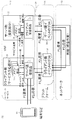
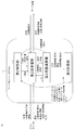
- FIG. 1 is a diagram illustrating a network service system according to the present invention.
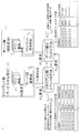
- FIG. 5 is a diagram illustrating an operation at the time of transmitting a request in the network service system according to the present invention.
- FIG. 7 is a diagram illustrating an operation at the time of replying back in the network service system according to the present invention.
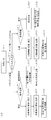
- FIG. 10 is a diagram illustrating an operation when the event logs do not match on the client side and the server side in the network service system according to the present invention.
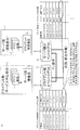
- FIG. 6 is a diagram illustrating an operation when performing service cooperation in consideration of a delay time in the network service system according to the present invention.
- FIG. 1 is a diagram illustrating a network service system according to the present invention.
- FIG. 5 is a diagram illustrating an operation at the time of transmitting a request in the network service system according to the present invention.
- FIG. 7 is a diagram illustrating an operation at the time of replying back in the network
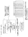
- FIG. 4 is a diagram illustrating an operation when a client device reconstructs a database in the network service system according to the present invention.
- FIG. 2 is a diagram illustrating a client-side event log recording device according to the present invention. It is a figure explaining the server side event log recording device concerning the present invention.
- FIG. 4 is a diagram illustrating an event log management method according to the present invention.
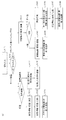
- FIG. 4 is a diagram illustrating the operation of the client-side event log recording device according to the present invention.
- FIG. 5 is a diagram illustrating the operation of the server-side event log recording device according to the present invention.
- FIG. 2 is a diagram illustrating the network service system according to the present embodiment.
- the adapter 50 is inserted in the middle of each service to be linked.
- the present invention is a platform 51 that records communication logs on both the server side and the client side in the adapter 50 and expresses the state thereof.
- the requesting side is referred to as a "client side (service center part) 21" and the receiving side is referred to as a “server side (receiving part) 22".
- the adapter 50 includes a “server transmission component 31” that is tightly coupled to the client side, a “client side event log DB 33” and a “server side event log DB 34” that record communication events between the client side and the server side, and a server side. And a "client receiving component 32" which is tightly coupled to the client.
- the network service system includes a procedure in which the client side (center part) connects to the server side (contracted part), a procedure in which the client side requests a command from the server side, Procedure for requesting a query from the server side, procedure for restoring communication from the event log DB when a communication failure occurs, procedure for ensuring real-time communication, and procedure for rebuilding the database when updating software I do.
- the network system of the present embodiment is a network service system that provides a service in response to a user request, A client device 21 for providing the service, A server device 22 that receives a part of the service processing in response to a request from the client device 21 and responds to the request; A platform 51 disposed on each of the client device 21 and the server device 22 to form two event log recording devices that relay communication between the client device 21 and the server device 22; Is provided.
- the terminal 10 is a device operated by a user when using a network, and can be loaded with a program for displaying a service screen and the like.
- the network service 40 provides a service in response to a request from the terminal 10.
- the service is generally configured as an aggregate of a plurality of virtual network functions (VNFs, Virtual Network Functions) on the cloud in order to ensure scalability.
- VNFs virtual network functions
- Virtual Network Functions Virtual Network Functions
- the client device 21 is the client side (center part) of the network service.
- the client device 21 provides a service in response to a request from the terminal 10.
- the service is assumed to be provided in a microservices architecture.
- the client device 21 has a main component 23 and a server transmission component 31.
- the group of main components 23 on the client side (center portion) is a group of VNF components in which business logic that is the core of the network service is mounted in the main portion. Scaling may be performed according to the used computer resource amount.
- the server transmission component 31 on the client side (center portion) is a VNF component that the main portion 23 mediates when making a request to the outsourced portion.
- the server transmission component 31 transmits / receives a request or response to / from the server via the client-side event log DB 33.
- the server transmission component 31 can receive the time stamp and the status information.
- the server device 22 is the server side (consignment part) of the network service.
- the server device 22 is not the core of the network service, but a part of the service is entrusted by a service provider.
- the server device 22 is configured as an aggregate of a plurality of virtual network functions (VNFs) on the cloud.
- the server device 22 has a main component 24 and a client receiving component 32.
- the group of main parts 24 on the server side (contract part) is a VNF parts group of the core part of the business logic of the service provided by the entrusted service provider in the consignment part.
- the client receiving component 32 on the server side (contracted portion) is a VNF component that functions as an adapter that mediates the previous stage when the server side accepts the request.
- the platform 51 includes two databases that record event logs on the client side and the server side, a function of maintaining the consistency of the databases, a function of recording communication failures, a function of synchronizing between databases, and a function of synchronizing between databases. Provides the ability to process queries.
- the two databases are a client-side event log database 33 and a server-side event log database 34.
- FIG. 8 is a configuration diagram illustrating the client-side event log database 33.
- the client-side event log database 33 Each time the request transmitted from the client device 21 to the server device 22 is generated, a first state calculation unit 83 that generates unique state information about the request; A first transmission / reception unit 82 that transmits the request and the state information generated by the first state calculation unit 83 to the server-side event log storage unit 34 for the server device 22 among the two event log storage units; A first storage unit 84 that records state information generated by the first state calculation unit 83 in association with the request, When the status information transmitted by the first transmission / reception unit 82 and the status information calculated by the server-side event log recording device 34 do not match, the status information recorded by the first storage unit 84 and the status information recorded by the server-side event log recording device 34 A first control unit 81 that retransmits the request and the state information recorded in the first storage unit 84 to the server-side event log recording device 34 until the time when the state information matches the request. Having.
- the client-side event log database 33 is installed at a position near the client device 21 on the network, and connects to the server transmission component 31 of the client device 21.
- the client-side event log database 33 holds a request (“command”) from the server transmission component 31 to the server side as an event log and transfers the request to the server-side event log DB 34.
- the client-side event log database 33 records the response received from the server-side event log DB 34 as an event log, and transfers the response to the server transmission component 31.
- the content stored in the client-side event log database 33 is such that the server transmission component 31 on the client side (center part) can acquire the event reception time, the log state, and the like as keys, analyze the history, and store the database of the client device 21 It can be used for rebuilding.
- FIG. 9 is a configuration diagram illustrating the server-side event log database 34.
- the server-side event log database 34 Each time the response transmitted from the server device 22 to the client device 21 occurs in response to the request, a second state calculation unit 93 that generates unique state information about the response; A second transmission / reception unit 92 for transmitting the response and the state information generated by the second state calculation unit 93 to the client-side event log recording device 33 for the client device 21 among the two event log recording devices; A second storage unit 94 for recording state information generated by the second state calculation unit 93 in association with the response, A second control unit 91; Has, The second transmission / reception unit 92 receives the request and the status information from the client-side event log recording device 33, passes the request to the server device 22, The second state calculation unit 93 generates unique state information on the request each time the second transmission / reception unit 02 receives the request, The second storage unit 94 records the state information generated by the second state calculation unit 93 in association with the request, When the status information received by the second transmission
- the server-side event log database 34 is installed on the connected client device 21 at a position near the server device 22 on the network, and is connected to the client receiving component 32 of the server device 22.
- the server-side event log database 34 holds a request (“command”) from the client-side event log DB 33 to the server as an event log and transfers the request to the client receiving component 32.
- the server-side event log database 34 records the response received from the client receiving component 31 as an event log, and transfers the response to the client-side event log DB 33.
- the server-side main component 24 When designing a service to be provided to the client side, the server-side main component 24 designs a request received by the server side by dividing the request into two patterns of a query (inquiry) and a command (instruction).
- the "query” inquires the status of the server.
- the "command” requests the server to change the state.
- the server-side client receiving component 32 has a function of connecting to the server-side event log database 34 of the platform 51 in response to a connection request from the platform 51.
- the server-side client receiving component 32 also has a function of measuring the time required for network communication with the client-side server transmitting component 31.
- the client-side main component 23 also designs a request to the server by dividing the request into two patterns of “query” and “command”.
- the client-side server transmission component 31 connects to the platform 51 from the main part 23 instead of connecting to the server side, and builds the client-side event log database 33 on the client side and the server side It has a function of requesting the construction of the side event log database 34.
- This event log management method A connection procedure S01 for forming two event log recording devices on the platform 51 at the request of the client device 21 and connecting the client device 21 and the server device 22 via the two event log recording devices; Each time the client-side event log recording device 33 for the client device 21 of the two event log recording devices generates the request transmitted from the client device 21 to the server device 22, unique status information about the request is generated.
- a first state calculation procedure S02 for generating The client-side event log recording device 33 transmits the request and the state information generated in the first state calculation procedure S02 to the server-side event log recording device 34 for the server device 22 among the two event log recording devices.
- a transmission procedure S03 A first storage procedure S04 in which the client-side event log recording device 33 records the state information generated in the first state calculation procedure S02 in association with the request;
- a delivery procedure S05 in which the server-side event log recording device 34 receives the request and the status information from the client-side event log recording device 33 and passes the request to the server device 22;
- the second state calculation procedure S06 in which the server-side event log recording device 34 generates unique state information on the response each time the response transmitted from the server device 22 to the client device 21 occurs in response to the request.
- connection procedure S01 will be described.
- the client-side main component 23 requests the platform 51 to build the client-side event log DB 33 and the server-side event log DB 34 via the server transmission component 31.
- the client-side main component 23 sends a client-side event to the platform 51 via the server transmission component 31 when connecting to the server-side main component 24.
- a connection between the log DB 33 and the server-side event log DB 34 is requested.
- the platform 51 records a log of all communications performed between the client device 21 and the server device 22.
- the client-side event log DB 33 records the requested event in the first storage unit 84 (first storage procedure S04), and the first state calculation unit 83 calculates unique “state information” representing the state. (First state calculation procedure S02) and record it in the first storage section 84 (first storage procedure S04).
- the first transceiver 82 transmits the status information to the server-side event log DB 34 (first transmission procedure S03, P1 2 requests FIG. 2).
- the first state calculation unit 83 creates state information by adding a hash value of a new event (command) to a past hash value, for example.
- the server transmission component 31 may record which of the plurality of main components 23 the request sent from corresponds to which of the transmission logs. Further, the client-side event log DB 33 may have a function of returning a transmission time and a calculated state (eg, a hash value) to the server transmission component 31 (P1x in FIG. 3). This function is such that, when a plurality of client-side main components 23 exist due to scale-out or the like, the server transmission component 31 performs matching between a request and a response, and any one of the plurality of main components 23 is selected. Can be used to determine if a response should be sent to
- the server-side event log DB 34 records the received request event in the second storage unit 94 and transmits the request event to the client receiving component 32. Then, the client receiving component 32 delivers the request event to the destination server-side main component 24 (delivery procedure S05).
- the server-side event log DB 34 calculates unique “state information” representing the state of the request event (third state calculation procedure S09). The third state calculation procedure S09 will be described later.
- the server-side main component 24 uses the result as a “response” as the client receiving component 32, the server-side event log DB 34, the client-side event log DB 33, and returns via the client server transmission component 31 (P2 in FIG. 2 and FIG. 4, P2 1, P2 2, P2 3, P2 4).
- the server sends part 31 includes a "request log state" associated with response P2 3 received, by the table with the corresponding main part 23, a response to the appropriate main components 23 May be delivered.
- server-side event log DB 34 records the response event in the second storage unit 94, calculates unique “state information” representing the state (second state calculation procedure S06), and obtains a new “state information” at that time.
- the “state” is recorded in the second storage unit 94 (second storage procedure S08).
- Server-side event log DB34 including also the condition, and transmits a response to the client-side event log DB 33 (second transmission procedure S07, P2 2 response in Figure 2).
- the 2DB mutually compares the communication logs stored in the first storage unit 84 and the second storage unit 94, and traces back to the time when the hash values match to determine at which stage of the request event the failure has occurred. Locate (collation procedure S10).
- the client-side event log DB 33 attempts to retransmit the event, going back to the point of occurrence of the failure in the event log (retransmission procedure S11). As a result, the two "states" match, and the event lost due to the communication failure is restored. Then, since the server-side event log DB 34 transmits the missing event to the client receiving component 32, the communication failure is not visible from the main components (23, 24), and the consistency is maintained.
- the client-side server transmission component 31 and the server-side client reception component 32 have a function of measuring a communication delay time therebetween and a communication time from the terminal 10 to the server transmission component 31.
- a method of real-time communication between a server and a client (replying a high-quality response within a limited communication time) using this function will be described with reference to FIG.
- the main part 23 of the network service entrusts some tasks to a plurality of entrusted parts, in order to minimize the time required for the entrustment, if the plural entrusted parts have a dependency relationship, the main part 23 requests them in order. If they do not have a dependency, they may be requested in parallel and the overall time may be adjusted.
- the present system further includes a measuring device that measures a communication delay time between the two communication devices,
- One communication device of the two communication devices is a response time limit obtained by subtracting a round-trip communication delay time measured by the measurement device from a maximum response time specified in the event, and the other of the two communication devices is a response time limit.
- Notify the communication device of The other communication device generates a plurality of processes from a process with a short time and a low level to a process with a long time and a high level with respect to the event, and among the plurality of processes, generates the highest level within the response deadline. Is returned to the one communication device as a response event to the event.
- the server transmission component 31 measures the communication time with the client reception component 32.
- the main component 23 specifies the desired maximum response time.
- the server transmission component 31 designates a value obtained by subtracting the network delay time for the round trip, which is the measured communication time, from the time specified by the main component 23 as the maximum time allowed in the response, and specifies the request P1 I do.
- Client receiving component 32 performs a request P1 4 to the main part 24, as a result, the main part 24, to the client receiving component 32, first performs a "response time is short but a lower quality response", then At an appropriate timing of the processing, the response time is lengthened to transmit a plurality of "higher quality responses" as much as possible.
- the server apparatus 22 as further subcontracting the part of the request P1 4 to another device (if acting as a client-side) is that the response time of the re-consignment is added to its own response time Become. Therefore, the server device 22, if the response time of the re-consignment is long, or if you can not understand the request P1 4 after receiving soon tentatively may be the default response.
- Server client receiving component 32 among the response P2 that are sequentially input from the main part 24, at an optimum timing in consideration of the delay time between the client device 21, to select the best response at that time, as a response P2 1 Is output to the side event log DB34.
- This response is transmitted to the main component 23 via the client-side event log DB 33 and the server transmission component 31 as described above.
- the two communication devices receive the partner event recorded by the storage unit of the event log recording device connected to the two communication devices, and reconstruct a database.
- a client-side event log DB 33 holds a communication log necessary for constructing a database of the client device 21. More specifically, the client-side event log DB 33 calculates the state information calculated from the request, the response from the server 22 (the partner event), and the response from the response so as to correspond to each request to the server 22. Recorded state information (partner state information).
- a new main component 23 is formed in the client device 21 by software update.
- the main component 23 makes a rebuild request P3 to the server transmission component 31 in order to rebuild the database.
- Server transmission component 31 receives the reconstructed according P3 rewind to the client-side event log DB33 sending requests P3 1.
- the client-side event log DB33 are together multiple response event P4 1 corresponding to the time and state information specified by the reconstruction according P3 to the server transmission component 31.
- the main part 23 receives a plurality of response event P4 2 from the server transmission component 31, to rebuild the database.
- each event log DB updates the state information (hash) for each request or response event during that time, so that the database is The occurrence of inconsistency before and after the construction can be suppressed.
- each of the two event log DBs assigns a unique state (example: hash value) to the request from the client device 21 and the response from the server device 22.
- this state (example: hash value) is regarded as an appropriate random value, it is considered that the value that the remainder of the arbitrary number can have is equal probability.
- the server transmission component 31 when the main part 23 of the client device 21 is scaled to a plurality, one response from the server device 22 is delivered to any one of the main parts 23.
- the server transmission component 31 if the server transmission component 31 is properly mounted, the destinations will be stochastically equal, so that the server transmission component 31 can distribute the response evenly to each main part 23.
- FIG. 11 is a flowchart summarizing the operation of the client-side event log recording device 33.
- the first transmission / reception unit 82 determines where the signal is from (Step S112). If the signal is a signal from the client device 21, the signal type is determined (step S113). If the signal type is "request”, the first state calculation unit 83 calculates state information (request) [request log state, for example, hash value] (step S114), and the first storage unit 84 determines "request”. The status information (request) is stored in association with the status information (step S115).
- the first control unit 81 sends “response” corresponding to the designated time or state information (request) from the first storage unit 84. Collected (step S117) and transmitted to the client device 21 (step S118).
- the type of the signal is determined (step S121). If the signal type is "response”, the first state computing unit 83 computes state information (response) [response log state, for example, a hash value] (step S122), and the first storage unit 84 determines "request”. The "response” and the state information (response) are stored in association with each other (step S123). Further, a “response” is transmitted to the client-side event log recording device 33 (step S124). On the other hand, if the signal type is “collation”, the first control unit 81 starts the collation work (step S125).
- step S125 The specific operation of the collation operation is that the client-side event log recording device 33 and the server-side event log recording device 34 cooperate with each other to store status information (request information) stored in the first storage unit 84 and the second storage unit 94. ) Is searched, and a time point of matching (a time point at which mismatching starts) is searched (step S145 in the server-side event log recording device 34). The first control unit 81 resends the “request” and the status information (request) that did not match as a result of the collation to the server-side event log recording device 34 (step S126).
- FIG. 12 is a flowchart summarizing the operation of the server-side event log recording device 34.
- the second transmission / reception unit 92 determines where the signal is from (Step S132). If the signal is a signal from the server device 22, the signal type is determined (step S133). If the signal type is "response", the second state calculation unit 93 calculates state information (response) [response log state, for example, hash value] (step S134), and the second storage unit 94 determines "request”. The “response” and the state information (response) are stored in association with each other (step S135).
- the “response” and the status information (response) are transmitted to the client-side event log recording device 33 (step S136).
- the second control unit 91 sends “request” corresponding to the designated time or status information (response) from the second storage unit 94.
- the data is collected (step S137) and transmitted to the client device 22 (step S138).
- the second state operation unit 93 outputs the state information (request) [request log state, for example, hash value ] (Step S141), and compares the result sent from the client-side event log recording device 33 with the calculated result (step S142). If they match, the second storage unit 94 stores the state information (request) in association with the "request” (step S143), and transmits the "request” to the server device 22 (step S144). On the other hand, if they do not match, the second control unit 91 requests the client-side event log recording device 33 to perform “collation”.
- step S145 The specific operation of the collation operation is that the client-side event log recording device 33 and the server-side event log recording device 34 cooperate with each other to store state information (request information) stored in the first storage unit 84 and the second storage unit 94. ) And search for a matching time point (a time point at which mismatch starts) (step S125 in the client-side event log recording device 33).
- the “request” and the status information (request) that did not match are retransmitted from the client-side event log recording device 33, and the second transmitting / receiving unit 92 receives this (step S146).
- the second storage unit 94 stores the retransmitted state information (request) in association with the “request” (step S147), and transmits the retransmitted “request” to the server device 22 (step S148).
- the "micro service” constituting the “network service” is divided into “server side” and “client side”, and communication between “server side” and “client side”. Is divided into “command” and “query”. Furthermore, the network service system of the present invention has a mechanism for recording logs only for "commands”, automatically intervening between communication between "server side” and “client side”, and records the communication between them as a log in a database. It has a mechanism for storing and updating state information every time each event log is recorded, and a mechanism for measuring communication time. (3) Effects With the above solution, the network service system of the present invention has the following effects, and solves the above problems. As described with reference to FIG.
- the transmission / reception data loss due to the communication failure can be restored.
- the database of the communication device at the time of updating or restarting the software can be reconstructed. It enables matching and equal distribution of requests and responses when microservices are scaled.
- Terminal 21 Client device (client-side communication device) 22: server device (server-side communication device) 23: Main component 24: Main component 31: Server transmission component 32: Client reception component 33: Client side event log recording device 34: Server side event log recording device 40: Network service 50: Adapter 51: Platform 52: Network 81: No. 1 control unit 82: first transmission / reception unit 83: first state calculation unit 84: first storage unit 91: second control unit 92: second transmission / reception unit 93: second state calculation unit 94: second storage unit
Landscapes
- Engineering & Computer Science (AREA)
- Theoretical Computer Science (AREA)
- Physics & Mathematics (AREA)
- General Engineering & Computer Science (AREA)
- General Physics & Mathematics (AREA)
- Computer Networks & Wireless Communication (AREA)
- Signal Processing (AREA)
- Data Exchanges In Wide-Area Networks (AREA)
- Small-Scale Networks (AREA)
- Debugging And Monitoring (AREA)
Abstract
通信障害による送受信データの欠落を復元することができるネットワークサービスシステム、イベントログ記録装置、イベントログ管理方法、及びプログラムを提供することを目的とする。 本発明に係るネットワークサービスシステムは、クライアント側イベントログ記録装置およびサーバ側イベントログ記録装置のそれぞれが、イベントが発生する度に、当該イベントのユニークな状態情報を生成し、生成した状態情報を相手側のイベントログ記録装置に送信するとともに当該イベントと対応付けてデータベースに記録し、相手側のイベントログ記録装置から受信した状態情報が自身の生成した状態情報と異なる場合には、両者の状態情報が一致する時点まで遡って、データベースに記録されたイベントを再送する。
Description
本開示は、マイクロサービスアーキテクチャを採用するネットワークサービスシステム、当該システムが備えるクライアント側イベントログ記録装置とサーバ側イベントログ記録装置、当該システムが行うイベントログ管理方法、及び当該記録装置を実現するプログラムに関する。
図1のように、ネットワークサービスAを複数の小さなサービス部品(B1、B2、・・・C)に分けることで、サービスの信頼性、可用性、スケーラビリティ及び開発効率を向上させる「マイクロサービス・アーキテクチャ」が普及しつつある。
また、サービスを「データ読み込み部」と「データ書き込み部」に分離することで、サービスのドメインを明確化する「命令・問い合わせ責任分離(CQRS)」設計パターンも普及している(例えば、非特許文献1を参照。)。
サービスを効率よく、迅速に開発するためには、自分でサービスに必要なすべての部品を開発するのではなく、一部のサービスについては他社サービスに依存するのが良い。しかし、実時間でサービスを提供するためには、一部を他社のサービスに依存するのは以下に説明する課題がある。
サービスが多様化・複雑化し、その実現のために、複数の特定用途の専門サービスの連携が重要になると、以下のような課題が発生する。
(信頼性の課題)
サービスの構築にあたり、自前で全てを開発するのではなく、多数の既存サービスを組み合わせると、サービスの信頼性もまた、組み合わせるサービスの数が多いほど低下する。たとえば稼働率99%の既存サービスを10個組み合わせ、それら全ての積が提供サービスの稼働率になる場合は、稼働率は90%程度まで低減してしまう。
サービスの構築にあたり、自前で全てを開発するのではなく、多数の既存サービスを組み合わせると、サービスの信頼性もまた、組み合わせるサービスの数が多いほど低下する。たとえば稼働率99%の既存サービスを10個組み合わせ、それら全ての積が提供サービスの稼働率になる場合は、稼働率は90%程度まで低減してしまう。
この問題への対処方法として、サービスへの要求と応答を全て、イベント化して双方でログを取り、サービス間連携において何らかの矛盾が発生した場合は、その前後で双方のログを照らし合わせることで、矛盾が発生した箇所を突き止める手法がある(イベント・ソーシング)。しかしこの手法は、サービスの提供側と利用側の双方で、ストレージの負担の大きなAPIを共通化する必要があるため、異なる組織間の手法として適用しにくいという課題がある。
また、サーバの処理能力が、物理リソースを超えた場合、スケーリング・サービス移動により、サーバ・クライアント間の通信が一時、途絶したり、再ルーティングが必要になることがある。その場合、サーバへの通信路が一旦途絶し、サービスがその間、中断してしまうという課題がある。
(実時間性の課題)
クライアントに提供するサービスの構成部品に外部のサービスを利用すると、ユーザに対して時間的な品質を担保するのが困難になるという課題がある。サービス提供にかかる時間は、一般に、ネットワークの遅延時間、計算機資源における処理時間の総計となるが、サービス連携によりそれらの一部がサービス提供者では制御できなくなるためである。また、一般のネットワークサービスでは、クライアントの位置は不定のため、まず、クライアント側からサービス側に対して「要求」を行い、それに対してサービスが「応答」を行う。そのため、通信が往復する時間がかかる。
クライアントに提供するサービスの構成部品に外部のサービスを利用すると、ユーザに対して時間的な品質を担保するのが困難になるという課題がある。サービス提供にかかる時間は、一般に、ネットワークの遅延時間、計算機資源における処理時間の総計となるが、サービス連携によりそれらの一部がサービス提供者では制御できなくなるためである。また、一般のネットワークサービスでは、クライアントの位置は不定のため、まず、クライアント側からサービス側に対して「要求」を行い、それに対してサービスが「応答」を行う。そのため、通信が往復する時間がかかる。
この問題の対処方法として、一般ユーザに近い場所にサービスを配置する手法が考えられるが(参考:エッジコンピューティング)、この手法は、あくまでもフロントサービスの配置手法であり、複数のサービスが連携する場合は、連携するサービス全てを移動することは一般に困難である。また、クライアントが体感するサービスの速度は、必ずしもクライアントとサーバ側フロント間で律速されるとは限らない。たとえば株式売買における指値取引のようなシステムでは、リアルタイム性はクライアント・サービス間ではなく、サービス・サービス間で求められる(参考・エージェント指向システム)。
(ソフトウェア更新に伴う課題)
更新されないソフトウェアは時間経過に伴い可用性が低下する。複数の異なるサービスを連携させる場合、サーバ(サービス提供側)とクライアント(サービス要求側)のどちらにおいても、ソフトウェアのバージョンの更新が非同期に行われる。バージョン更新に伴い、データベースなどのスキーマが変更し、従来は重要視されておらず通信後は捨てられていたようなデータがあらためて必要になる場合、過去の通信ログなどを使って、データベースを再度作り直す必要性が生じるという課題がある。
更新されないソフトウェアは時間経過に伴い可用性が低下する。複数の異なるサービスを連携させる場合、サーバ(サービス提供側)とクライアント(サービス要求側)のどちらにおいても、ソフトウェアのバージョンの更新が非同期に行われる。バージョン更新に伴い、データベースなどのスキーマが変更し、従来は重要視されておらず通信後は捨てられていたようなデータがあらためて必要になる場合、過去の通信ログなどを使って、データベースを再度作り直す必要性が生じるという課題がある。
(他の課題)
サービス連携におけるサーバ(サービス提供側)やクライアント(サービス要求側)ともに、スケーリングや移動などによってデータが失われる場合がある。また、サーバ・クライアント間のネットワークも、一時的な通信オーバーフローや故障等により、データを転送できなくなる場合がある。その場合、データの不達の責任は、サーバ・クライアント・ネットワークの3者のどれにあるのか、客観的に証明することは困難で、サーバが提供するサービスの対価を支払う責任の有無の判断が困難になるという課題もある。また、データの不整合を修正する通信を行うと、他のリアルタイム性の高い通信がブロックされる問題がある。
サービス連携におけるサーバ(サービス提供側)やクライアント(サービス要求側)ともに、スケーリングや移動などによってデータが失われる場合がある。また、サーバ・クライアント間のネットワークも、一時的な通信オーバーフローや故障等により、データを転送できなくなる場合がある。その場合、データの不達の責任は、サーバ・クライアント・ネットワークの3者のどれにあるのか、客観的に証明することは困難で、サーバが提供するサービスの対価を支払う責任の有無の判断が困難になるという課題もある。また、データの不整合を修正する通信を行うと、他のリアルタイム性の高い通信がブロックされる問題がある。
前記課題を解決するために、本発明は、通信障害による送受信データの欠落を復元することができるネットワークサービスシステム、イベントログ記録装置、イベントログ管理方法、及びプログラムを提供することを目的とする。
上記目的を達成するために、本発明に係るネットワークサービスシステムは、連携する各サービスの中間にアダプタを挿入し、当該アダプタでサーバ側とクライアント側で通信ログを記録することとした。
具体的には、本発明に係るネットワークサービスシステムは、2つの通信装置の間で通信イベントを送受するネットワークサービスシステムであって、
前記2つの通信装置の各々に接続され、前記2つの通信装置の間の通信を中継する2つのイベントログ記録装置を備え、
前記イベントログ記録装置は、
前記2つの通信装置のうち、接続している通信装置にイベントが発生する度に、前記イベントのユニークな状態情報を生成する状態演算部と、
前記イベントと前記状態演算部が生成した状態情報を相手側のイベントログ記録装置に送信するとともに、前記相手側のイベントログ記録装置からの相手イベントと相手状態情報を受信する送受信部と、
前記状態演算部が生成した状態情報を前記イベントと対応付けて記録する記憶部と、
前記送受信部が前記相手イベントと前記相手状態情報を受信したときに、前記状態演算部に前記相手イベントのユニークな状態情報を生成させ、当該状態情報と前記相手状態情報とが異なる場合、前記記憶部に記録する状態情報と前記相手側のイベントログ記録装置が記録する相手状態情報を照合して両者が一致する時点まで遡って、前記記憶部に記録されたイベントを前記送受信部に再送させる制御部と、
を有することを特徴とする。
前記2つの通信装置の各々に接続され、前記2つの通信装置の間の通信を中継する2つのイベントログ記録装置を備え、
前記イベントログ記録装置は、
前記2つの通信装置のうち、接続している通信装置にイベントが発生する度に、前記イベントのユニークな状態情報を生成する状態演算部と、
前記イベントと前記状態演算部が生成した状態情報を相手側のイベントログ記録装置に送信するとともに、前記相手側のイベントログ記録装置からの相手イベントと相手状態情報を受信する送受信部と、
前記状態演算部が生成した状態情報を前記イベントと対応付けて記録する記憶部と、
前記送受信部が前記相手イベントと前記相手状態情報を受信したときに、前記状態演算部に前記相手イベントのユニークな状態情報を生成させ、当該状態情報と前記相手状態情報とが異なる場合、前記記憶部に記録する状態情報と前記相手側のイベントログ記録装置が記録する相手状態情報を照合して両者が一致する時点まで遡って、前記記憶部に記録されたイベントを前記送受信部に再送させる制御部と、
を有することを特徴とする。
ここで、本発明に係るイベントログ装置は、2つの通信装置の間で通信イベントを送受するネットワークサービスシステムにおいて、前記2つの通信装置毎に接続され、前記2つの通信装置の間の通信を中継するイベントログ記録装置であって、
前記2つの通信装置のうち、接続している通信装置にイベントが発生する度に、前記イベントのユニークな状態情報を生成する状態演算部と、
前記イベントと前記状態演算部が生成した状態情報を相手側のイベントログ記録装置に送信するとともに、前記相手側のイベントログ記録装置からの相手イベントと相手状態情報を受信する送受信部と、
前記状態演算部が生成した状態情報を前記イベントと対応付けて記録する記憶部と、
前記送受信部が前記相手イベントと前記相手状態情報を受信したときに、前記状態演算部に前記相手イベントのユニークな状態情報を生成させ、当該状態情報と前記相手状態情報とが異なる場合、前記記憶部に記録する状態情報と前記相手側のイベントログ記録装置が記録する相手状態情報を照合して両者が一致する時点まで遡って、前記記憶部に記録されたイベントを前記送受信部に再送させる制御部と、
を有することを特徴とする。
前記2つの通信装置のうち、接続している通信装置にイベントが発生する度に、前記イベントのユニークな状態情報を生成する状態演算部と、
前記イベントと前記状態演算部が生成した状態情報を相手側のイベントログ記録装置に送信するとともに、前記相手側のイベントログ記録装置からの相手イベントと相手状態情報を受信する送受信部と、
前記状態演算部が生成した状態情報を前記イベントと対応付けて記録する記憶部と、
前記送受信部が前記相手イベントと前記相手状態情報を受信したときに、前記状態演算部に前記相手イベントのユニークな状態情報を生成させ、当該状態情報と前記相手状態情報とが異なる場合、前記記憶部に記録する状態情報と前記相手側のイベントログ記録装置が記録する相手状態情報を照合して両者が一致する時点まで遡って、前記記憶部に記録されたイベントを前記送受信部に再送させる制御部と、
を有することを特徴とする。
つまり、本発明に係るイベントログ管理方法は、2つの通信装置の間で通信イベントを送受するネットワークサービスシステムのイベントログ管理方法であって、
前記2つの通信装置の各々に接続され、前記2つの通信装置の間の通信を中継する2つのイベントログ記録装置をプラットフォームに形成する接続手順と、
前記2つの通信装置のうち、接続している通信装置にイベントが発生する度に、前記イベントのユニークな状態情報を生成する状態演算手順と、
前記イベントと前記状態演算手順で生成した状態情報を相手側のイベントログ記録装置に送信する送信手順と、
前記状態演算部が生成した状態情報を前記イベントと対応付けて記録する記憶手順と、
前記相手側のイベントログ記録装置からの相手イベントと相手状態情報を受信する受信手順と、
前記受信手順で前記相手イベントと前記相手状態情報を受信したときに、前記相手イベントのユニークな状態情報を生成し、当該状態情報と前記相手状態情報とが異なる場合、前記記憶手順で記録する状態情報と前記相手側のイベントログ記録装置が記録する相手状態情報を照合して両者が一致する時点まで遡って、前記記憶部に記録されたイベントを前記相手側のイベントログ記録装置へ再送する再送手順と、
を行うことを特徴とする。
前記2つの通信装置の各々に接続され、前記2つの通信装置の間の通信を中継する2つのイベントログ記録装置をプラットフォームに形成する接続手順と、
前記2つの通信装置のうち、接続している通信装置にイベントが発生する度に、前記イベントのユニークな状態情報を生成する状態演算手順と、
前記イベントと前記状態演算手順で生成した状態情報を相手側のイベントログ記録装置に送信する送信手順と、
前記状態演算部が生成した状態情報を前記イベントと対応付けて記録する記憶手順と、
前記相手側のイベントログ記録装置からの相手イベントと相手状態情報を受信する受信手順と、
前記受信手順で前記相手イベントと前記相手状態情報を受信したときに、前記相手イベントのユニークな状態情報を生成し、当該状態情報と前記相手状態情報とが異なる場合、前記記憶手順で記録する状態情報と前記相手側のイベントログ記録装置が記録する相手状態情報を照合して両者が一致する時点まで遡って、前記記憶部に記録されたイベントを前記相手側のイベントログ記録装置へ再送する再送手順と、
を行うことを特徴とする。
本ネットワークサービスシステムは、クライアント側イベントログ記録装置およびサーバ側イベントログ記録装置のそれぞれが、イベント(クライアント装置からサーバ装置へ送信される「要求(コマンド)」、および該「要求」に対してサーバ装置からクライアント装置へ送信される「応答」)が発生する度に、当該イベントのユニークな状態情報を生成し、生成した状態情報を相手側のイベントログ記録装置に送信するとともに当該イベントと対応付けてデータベースに記録し、相手側のイベントログ記録装置から受信した状態情報が自身の生成した状態情報と異なる場合には、両者の状態情報が一致する時点まで遡って、データベースに記録されたイベントを再送する。
従って、本発明は、通信障害による送受信データの欠落を復元することができるネットワークサービスシステム、イベントログ記録装置、及びイベントログ管理方法を提供することができる。
本発明に係るネットワークサービスシステムは、前記2つの通信装置の間の通信遅延時間を計測する計測装置をさらに備え、
前記2つの通信装置のうちの一方の通信装置は、前記イベントに指定された最大応答時間から前記計測装置が計測した往復の通信遅延時間を差し引いた応答期限を前記2つの通信装置のうちの他方の通信装置に通知し、
前記他方の通信装置は、前記イベントに対して時間が短くレベルの低い処理から時間が長くレベルの高い処理までの複数の処理を生成し、前記複数の処理の中から前記応答期限内で最もレベルの高い処理を前記イベントに対する応答のイベントとして前記一方の通信装置へ返信することを特徴とする。
本ネットワークサービスシステムは、サーバ装置がクライアント装置に対して、指定された時間以内に最大の品質の応答を返すことができる。
前記2つの通信装置のうちの一方の通信装置は、前記イベントに指定された最大応答時間から前記計測装置が計測した往復の通信遅延時間を差し引いた応答期限を前記2つの通信装置のうちの他方の通信装置に通知し、
前記他方の通信装置は、前記イベントに対して時間が短くレベルの低い処理から時間が長くレベルの高い処理までの複数の処理を生成し、前記複数の処理の中から前記応答期限内で最もレベルの高い処理を前記イベントに対する応答のイベントとして前記一方の通信装置へ返信することを特徴とする。
本ネットワークサービスシステムは、サーバ装置がクライアント装置に対して、指定された時間以内に最大の品質の応答を返すことができる。
本発明に係るネットワークサービスシステムの前記記憶部は、前記送受信部が受信した、前記イベントに応答する相手イベントと相手状態情報も前記イベントに対応付けて記録しており、前記2つの通信装置は、自身が変更された場合、自身に接続する前記イベントログ記録装置の前記記憶部が記録する前記相手イベントを受け取り、データベースを再構築することを特徴とする。本ネットワークサービスシステムは、通信装置のデータベースを構築するのに必要な通信ログを、アダプタのイベントログ記録装置が保持している。このため、本ネットワークサービスシステムは、クライアント装置やサーバ装置のソフトウェアのバージョン更新時にこれらのログからデータベースを再構築することができる。
本発明は、前記イベントログ記録装置としてコンピュータを機能させるためのプログラムである。本発明に係るイベントログ記録装置は、コンピュータとプログラムによっても実現でき、プログラムを記録媒体に記録することも、ネットワークを通して提供することも可能である。
本発明は、通信障害による送受信データの欠落を復元することができるネットワークサービスシステム、イベントログ記録装置、イベントログ管理方法、及びプログラムを提供することができる。
添付の図面を参照して本発明の実施形態を説明する。以下に説明する実施形態は本発明の実施例であり、本発明は、以下の実施形態に制限されるものではない。なお、本明細書及び図面において符号が同じ構成要素は、相互に同一のものを示すものとする。
[発明概要]
図2は、本実施形態のネットワークサービスシステムを説明する図である。
前述した「信頼性」、「実時間性」、「継続的ソフトウェア更新」、その他の諸問題を解決するために、本発明では、連携する各サービスの中間にアダプタ50を挿入する。
本発明は、アダプタ50において、サーバ側とクライアント側の双方で通信ログを記録し、その状態を表現するプラットフォーム51である。
図2は、本実施形態のネットワークサービスシステムを説明する図である。
前述した「信頼性」、「実時間性」、「継続的ソフトウェア更新」、その他の諸問題を解決するために、本発明では、連携する各サービスの中間にアダプタ50を挿入する。
本発明は、アダプタ50において、サーバ側とクライアント側の双方で通信ログを記録し、その状態を表現するプラットフォーム51である。
ネットワークサービス40においてサービスを連携する際、依頼する側を「クライアント側(サービス中心部分)21」、受託する側を「サーバ側(受託部分)22」とする。アダプタ50は、クライアント側に密結合する「サーバ送信部品31」、クライアント側とサーバ側との間の通信イベントを記録する「クライアント側イベントログDB33」と「サーバ側イベントログDB34」、およびサーバ側に密結合する「クライアント受信部品32」から構成される。
そして、上記の諸問題を解決するため、本実施形態のネットワークサービスシステムは、クライアント側(中心部分)がサーバ側(受託部分)と接続する手順、クライアント側がサーバ側にコマンドを要求する手順、クライアント側がサーバ側にクエリを要求する手順、通信に障害が発生した際に、イベントログDBから通信を復元する手順、通信の実時間性を保証する手順、及びソフトウェアの更新時におけるデータベースの再構築手順を行う。
[構成の説明]
本実施形態のネットワークシステムは、ユーザの要求に対してサービスを提供するネットワークサービスシステムであって、
前記サービスを提供するクライアント装置21と、
クライアント装置21の要求により前記サービスの一部の処理を受託し、前記要求に対する応答を行うサーバ装置22と、
クライアント装置21とサーバ装置22のそれぞれに配置され、クライアント装置21とサーバ装置22との間の通信を中継する2つのイベントログ記録装置が形成されるプラットフォーム51と、
を備える。
本実施形態のネットワークシステムは、ユーザの要求に対してサービスを提供するネットワークサービスシステムであって、
前記サービスを提供するクライアント装置21と、
クライアント装置21の要求により前記サービスの一部の処理を受託し、前記要求に対する応答を行うサーバ装置22と、
クライアント装置21とサーバ装置22のそれぞれに配置され、クライアント装置21とサーバ装置22との間の通信を中継する2つのイベントログ記録装置が形成されるプラットフォーム51と、
を備える。
(端末とネットワークサービス)
端末10は、ユーザがネットワークを利用する際に操作するデバイスであり、サービス画面などを表示するプログラムを搭載することができる。
ネットワークサービス40は、端末10からの要求に対してサービスを提供する。サービスは一般には、スケーラビリティを確保するため、クラウド上に複数の仮想ネットワーク機能(VNF, Virtual Network Function)の集合体として構成される。
端末10は、ユーザがネットワークを利用する際に操作するデバイスであり、サービス画面などを表示するプログラムを搭載することができる。
ネットワークサービス40は、端末10からの要求に対してサービスを提供する。サービスは一般には、スケーラビリティを確保するため、クラウド上に複数の仮想ネットワーク機能(VNF, Virtual Network Function)の集合体として構成される。
(ネットワークサービスのクライアント側(中心部分))
クライアント装置21がネットワークサービスのクライアント側(中心部分)である。
クライアント装置21は、端末10からの要求に対してサービスを提供する。当該サービスは、マイクロサービス・アーキテクチャで提供されることを前提とする。クライアント装置21は、メイン部品23とサーバ送信部品31を有する。
クライアント側(中心部分)のメイン部品23群は、メイン部分における、ネットワークサービスの中核となるビジネスロジックが実装されているVNF部品群である。使用計算機資源量に応じて、スケーリングをしても良い。
クライアント側(中心部分)のサーバ送信部品31は、メイン部分23が、外部委託部分に要求を行う際に仲介するVNF部品である。サーバ送信部品31は、サーバ側への要求ないし応答の送受信にクライアント側イベントログDB33を経由させる。また、サーバ送信部品31は、要求をクライアント側イベントログDB33に送信する際に、そのタイムスタンプや状態情報を受け取ることができる。
クライアント装置21がネットワークサービスのクライアント側(中心部分)である。
クライアント装置21は、端末10からの要求に対してサービスを提供する。当該サービスは、マイクロサービス・アーキテクチャで提供されることを前提とする。クライアント装置21は、メイン部品23とサーバ送信部品31を有する。
クライアント側(中心部分)のメイン部品23群は、メイン部分における、ネットワークサービスの中核となるビジネスロジックが実装されているVNF部品群である。使用計算機資源量に応じて、スケーリングをしても良い。
クライアント側(中心部分)のサーバ送信部品31は、メイン部分23が、外部委託部分に要求を行う際に仲介するVNF部品である。サーバ送信部品31は、サーバ側への要求ないし応答の送受信にクライアント側イベントログDB33を経由させる。また、サーバ送信部品31は、要求をクライアント側イベントログDB33に送信する際に、そのタイムスタンプや状態情報を受け取ることができる。
(ネットワークサービスのサーバ側(受託部分))
サーバ装置22がネットワークサービスのサーバ側(受託部分)である。サーバ装置22は、ネットワークサービスのうち、サービスの中核でなく、サービス提供者からサービスの一部が委託される。通常、サーバ装置22は、クラウド上に複数の仮想ネットワーク機能(VNF)の集合体として構成される。サーバ装置22は、メイン部品24とクライアント受信部品32を有する。
サーバ側(受託部分)のメイン部分24群は、受託部分のうち、委託されたサービス事業者が提供するサービスのビジネスロジックの中核部分のVNF部品群である。
サーバ側(受託部分)のクライアント受信部品32は、サーバ側が、要求を受け付ける際に、その前段階を仲介するアダプタとなるVNF部品である。
サーバ装置22がネットワークサービスのサーバ側(受託部分)である。サーバ装置22は、ネットワークサービスのうち、サービスの中核でなく、サービス提供者からサービスの一部が委託される。通常、サーバ装置22は、クラウド上に複数の仮想ネットワーク機能(VNF)の集合体として構成される。サーバ装置22は、メイン部品24とクライアント受信部品32を有する。
サーバ側(受託部分)のメイン部分24群は、受託部分のうち、委託されたサービス事業者が提供するサービスのビジネスロジックの中核部分のVNF部品群である。
サーバ側(受託部分)のクライアント受信部品32は、サーバ側が、要求を受け付ける際に、その前段階を仲介するアダプタとなるVNF部品である。
(プラットフォーム)
プラットフォーム51は、クライアント側およびサーバ側におけるイベントログを記録する2つのデータベースを備え、そのデータベースの整合性を維持する機能、通信障害を記録する機能、データベース間で同期する機能、及びクライアント側からの問い合わせを処理する機能を提供する。前記2つのデータベースは、クライアント側イベントログデータベース33とサーバ側イベントログデータベース34である。
プラットフォーム51は、クライアント側およびサーバ側におけるイベントログを記録する2つのデータベースを備え、そのデータベースの整合性を維持する機能、通信障害を記録する機能、データベース間で同期する機能、及びクライアント側からの問い合わせを処理する機能を提供する。前記2つのデータベースは、クライアント側イベントログデータベース33とサーバ側イベントログデータベース34である。
図8は、クライアント側イベントログデータベース33を説明する構成図である。クライアント側イベントログデータベース33は、
クライアント装置21からサーバ装置22へ送信される前記要求が発生する度に、前記要求についてのユニークな状態情報を生成する第1状態演算部83と、
前記2つのイベントログ記録装置のうちサーバ装置22用のサーバ側イベントログ記録装置34へ、前記要求及び第1状態演算部83が生成した状態情報を送信する第1送受信部82と、
前記要求と対応付けて第1状態演算部83が生成した状態情報を記録する第1記憶部84と、
第1送受信部82が送信した状態情報とサーバ側イベントログ記録装置34で計算した状態情報が不一致であった時点から第1記憶部84が記録する状態情報とサーバ側イベントログ記録装置34が記録する状態情報とが一致する時点までの、第1記憶部84が記録する前記要求及び状態情報をサーバ側イベントログ記録装置34へ再送させる第1制御部81と、
を有する。
クライアント装置21からサーバ装置22へ送信される前記要求が発生する度に、前記要求についてのユニークな状態情報を生成する第1状態演算部83と、
前記2つのイベントログ記録装置のうちサーバ装置22用のサーバ側イベントログ記録装置34へ、前記要求及び第1状態演算部83が生成した状態情報を送信する第1送受信部82と、
前記要求と対応付けて第1状態演算部83が生成した状態情報を記録する第1記憶部84と、
第1送受信部82が送信した状態情報とサーバ側イベントログ記録装置34で計算した状態情報が不一致であった時点から第1記憶部84が記録する状態情報とサーバ側イベントログ記録装置34が記録する状態情報とが一致する時点までの、第1記憶部84が記録する前記要求及び状態情報をサーバ側イベントログ記録装置34へ再送させる第1制御部81と、
を有する。
クライアント側イベントログデータベース33は、ネットワーク上のクライアント装置21に近い位置に設置され、クライアント装置21のサーバ送信部品31と接続する。クライアント側イベントログデータベース33は、サーバ送信部品31からサーバ側への要求(「コマンド」)をイベントログとして保持し、サーバ側イベントログDB34へ転送する。また、クライアント側イベントログデータベース33は、サーバ側イベントログDB34から受信した応答をイベントログとして記録し、サーバ送信部品31へ転送する。
クライアント側イベントログデータベース33が記憶する内容は、クライアント側(中心部分)のサーバ送信部品31が、イベント受信時刻やログ状態等をキーに取得することができ、履歴の分析やクライアント装置21のデータベースの再構築等に利用できる。
クライアント側イベントログデータベース33が記憶する内容は、クライアント側(中心部分)のサーバ送信部品31が、イベント受信時刻やログ状態等をキーに取得することができ、履歴の分析やクライアント装置21のデータベースの再構築等に利用できる。
図9は、サーバ側イベントログデータベース34を説明する構成図である。サーバ側イベントログデータベース34は、
前記要求に対してサーバ装置22からクライアント装置21へ送信される前記応答が発生する度に、前記応答についてのユニークな状態情報を生成する第2状態演算部93と、
前記2つのイベントログ記録装置のうちクライアント装置21用のクライアント側イベントログ記録装置33へ前記応答及び第2状態演算部93が生成した状態情報を送信する第2送受信部92と、
前記応答と対応付けて第2状態演算部93が生成した状態情報を記録する第2記憶部94と、
第2制御部91と、
を有しており、
第2送受信部92は、クライアント側イベントログ記録装置33からの前記要求及び状態情報を受信し、サーバ装置22へ前記要求を引き渡し、
第2状態演算部93は、第2送受信部02が前記要求を受信する度に、前記要求についてのユニークな状態情報を生成し、
第2記憶部94は、前記要求と対応付けて第2状態演算部93が生成した状態情報を記録し、
第2制御部91は、第2送受信部92が受信した状態情報と第2状態演算部93が演算した状態情報とが異なる場合、第2記憶部94が記録する前記要求と対応付けた状態情報とクライアント側イベントログ記録装置33が記録する前記要求と対応付けた状態情報とを照合することを特徴とする。
前記要求に対してサーバ装置22からクライアント装置21へ送信される前記応答が発生する度に、前記応答についてのユニークな状態情報を生成する第2状態演算部93と、
前記2つのイベントログ記録装置のうちクライアント装置21用のクライアント側イベントログ記録装置33へ前記応答及び第2状態演算部93が生成した状態情報を送信する第2送受信部92と、
前記応答と対応付けて第2状態演算部93が生成した状態情報を記録する第2記憶部94と、
第2制御部91と、
を有しており、
第2送受信部92は、クライアント側イベントログ記録装置33からの前記要求及び状態情報を受信し、サーバ装置22へ前記要求を引き渡し、
第2状態演算部93は、第2送受信部02が前記要求を受信する度に、前記要求についてのユニークな状態情報を生成し、
第2記憶部94は、前記要求と対応付けて第2状態演算部93が生成した状態情報を記録し、
第2制御部91は、第2送受信部92が受信した状態情報と第2状態演算部93が演算した状態情報とが異なる場合、第2記憶部94が記録する前記要求と対応付けた状態情報とクライアント側イベントログ記録装置33が記録する前記要求と対応付けた状態情報とを照合することを特徴とする。
サーバ側イベントログデータベース34は、ネットワーク上のサーバ装置22に近い位置に、接続されるクライアント装置21に設置され、サーバ装置22のクライアント受信部品32と接続される。サーバ側イベントログデータベース34は、クライント側イベントログDB33からサーバ側への要求(「コマンド」)をイベントログとして保持し、クライアント受信部品32へ転送する。また、サーバ側イベントログデータベース34は、クライアント受信部品31から受信した応答をイベントログとして記録し、クライアント側イベントログDB33へ転送する。
ここで、クライアント装置21とサーバ装置22に形成されるVNFの各部品について説明する。
サーバ側メイン部品24は、クライアント側に提供するサービスを設計する際に、サーバ側が受信する要求を、クエリ(問い合わせ)とコマンド(命令)2パターンに分けて設計する。「クエリ」は、サーバへの状態の問い合わせを行う。「コマンド」は、サーバ側に状態の変更を要請する。
サーバ側クライアント受信部品32は、プラットフォーム51からの接続要求に応じ、プラットフォーム51のサーバ側イベントログデータベース34に接続する機能を有する。また、サーバ側クライアント受信部品32は、クライアント側サーバ送信部品31との間でネットワークの通信に要する時間を計測する機能も有する。
クライアント側メイン部品23もまた、サーバへの要求を、「クエリ」と「コマンド」の2パターンに分けて設計する。
クライアント側サーバ送信部品31は、メイン部分23から、サーバ側に接続する代わりに、プラットフォーム51に接続し、プラットフォーム51に対して、クライアント側にクライアント側イベントログデータベース33の構築を、サーバ側にサーバ側イベントログデータベース34の構築を要求する機能を有する。
サーバ側メイン部品24は、クライアント側に提供するサービスを設計する際に、サーバ側が受信する要求を、クエリ(問い合わせ)とコマンド(命令)2パターンに分けて設計する。「クエリ」は、サーバへの状態の問い合わせを行う。「コマンド」は、サーバ側に状態の変更を要請する。
サーバ側クライアント受信部品32は、プラットフォーム51からの接続要求に応じ、プラットフォーム51のサーバ側イベントログデータベース34に接続する機能を有する。また、サーバ側クライアント受信部品32は、クライアント側サーバ送信部品31との間でネットワークの通信に要する時間を計測する機能も有する。
クライアント側メイン部品23もまた、サーバへの要求を、「クエリ」と「コマンド」の2パターンに分けて設計する。
クライアント側サーバ送信部品31は、メイン部分23から、サーバ側に接続する代わりに、プラットフォーム51に接続し、プラットフォーム51に対して、クライアント側にクライアント側イベントログデータベース33の構築を、サーバ側にサーバ側イベントログデータベース34の構築を要求する機能を有する。
図10を用いて、本実施形態のネットワークサービスシステムの動作であるイベントログ管理方法について説明する。本イベントログ管理方法は、
クライアント装置21の要請でプラットフォーム51に2つのイベントログ記録装置を形成し、前記2つのイベントログ記録装置を介してクライアント装置21とサーバ装置22とを接続する接続手順S01と、
前記2つのイベントログ記録装置のうちクライアント装置21用のクライアント側イベントログ記録装置33が、クライアント装置21からサーバ装置22へ送信される前記要求が発生する度に、前記要求についてのユニークな状態情報を生成する第1状態演算手順S02と、
クライアント側イベントログ記録装置33が、前記2つのイベントログ記録装置のうちサーバ装置22用のサーバ側イベントログ記録装置34へ、前記要求及び第1状態演算手順S02で生成した状態情報を送信する第1送信手順S03と、
クライアント側イベントログ記録装置33が、前記要求と対応付けて第1状態演算手順S02で生成した状態情報を記録する第1記憶手順S04と、
サーバ側イベントログ記録装置34が、クライアント側イベントログ記録装置33からの前記要求及び状態情報を受信し、サーバ装置22へ前記要求を引き渡す送達手順S05と、
サーバ側イベントログ記録装置34が、前記要求に対してサーバ装置22からクライアント装置21へ送信される前記応答が発生する度に、前記応答についてのユニークな状態情報を生成する第2状態演算手順S06と、
サーバ側イベントログ記録装置34が、クライアント側イベントログ記録装置33へ前記応答及び第2状態演算手順S06で生成した状態情報を送信する第2送信手順S07と、
サーバ側イベントログ記録装置34が、前記応答と対応付けて第2状態演算手順S06で生成した状態情報を記録する第2記憶手順S08と、
サーバ側イベントログ記録装置34が、クライアント側イベントログ記録装置33から前記要求を受信する度に、前記要求についてのユニークな状態情報を生成する第3状態演算手順S09と、
クライアント側イベントログ記録装置33から受信した状態情報と第3状態演算手順S09で演算した状態情報とが異なる場合、クライアント側イベントログ記録装置33とサーバ側イベントログ記録装置34が、両者が記録する状態情報を照合し、両者が記録する状態情報が一致する状態一致時点を検索する照合手順S10と、
前記照合手順で検索した前記状態一致時点から、前記クライアント側イベントログ記録装置から受信した状態情報と前記第3状態演算手順で演算した状態情報とが異なっている時点までの、前記第1記憶手順で記録する前記要求を、前記クライアント側イベントログ記録装置がサーバ側イベントログ記録装置34へ再送する再送手順S11と、
を行うことを特徴とする。
クライアント装置21の要請でプラットフォーム51に2つのイベントログ記録装置を形成し、前記2つのイベントログ記録装置を介してクライアント装置21とサーバ装置22とを接続する接続手順S01と、
前記2つのイベントログ記録装置のうちクライアント装置21用のクライアント側イベントログ記録装置33が、クライアント装置21からサーバ装置22へ送信される前記要求が発生する度に、前記要求についてのユニークな状態情報を生成する第1状態演算手順S02と、
クライアント側イベントログ記録装置33が、前記2つのイベントログ記録装置のうちサーバ装置22用のサーバ側イベントログ記録装置34へ、前記要求及び第1状態演算手順S02で生成した状態情報を送信する第1送信手順S03と、
クライアント側イベントログ記録装置33が、前記要求と対応付けて第1状態演算手順S02で生成した状態情報を記録する第1記憶手順S04と、
サーバ側イベントログ記録装置34が、クライアント側イベントログ記録装置33からの前記要求及び状態情報を受信し、サーバ装置22へ前記要求を引き渡す送達手順S05と、
サーバ側イベントログ記録装置34が、前記要求に対してサーバ装置22からクライアント装置21へ送信される前記応答が発生する度に、前記応答についてのユニークな状態情報を生成する第2状態演算手順S06と、
サーバ側イベントログ記録装置34が、クライアント側イベントログ記録装置33へ前記応答及び第2状態演算手順S06で生成した状態情報を送信する第2送信手順S07と、
サーバ側イベントログ記録装置34が、前記応答と対応付けて第2状態演算手順S06で生成した状態情報を記録する第2記憶手順S08と、
サーバ側イベントログ記録装置34が、クライアント側イベントログ記録装置33から前記要求を受信する度に、前記要求についてのユニークな状態情報を生成する第3状態演算手順S09と、
クライアント側イベントログ記録装置33から受信した状態情報と第3状態演算手順S09で演算した状態情報とが異なる場合、クライアント側イベントログ記録装置33とサーバ側イベントログ記録装置34が、両者が記録する状態情報を照合し、両者が記録する状態情報が一致する状態一致時点を検索する照合手順S10と、
前記照合手順で検索した前記状態一致時点から、前記クライアント側イベントログ記録装置から受信した状態情報と前記第3状態演算手順で演算した状態情報とが異なっている時点までの、前記第1記憶手順で記録する前記要求を、前記クライアント側イベントログ記録装置がサーバ側イベントログ記録装置34へ再送する再送手順S11と、
を行うことを特徴とする。
[クライアント側(中心部分)がサーバ側(受託部分)と接続する手順]
まず、接続手順S01を説明する。
クライアント側メイン部品23は、サーバ側メイン部品24と接続する際に、サーバ送信部品31を経由し、プラットフォーム51に対してクライアント側イベントログDB33およびサーバ側イベントログDB34の構築を要請する。
プラットフォーム51が2つのイベントログデータベースの構築を完了した後、クライアント側メイン部品23は、サーバ側メイン部品24と接続する際に、サーバ送信部品31を経由し、プラットフォーム51に対して、クライアント側イベントログDB33およびサーバ側イベントログDB34との間の接続を要請する。
当該接続が確立すると、プラットフォーム51は、クライアント装置21とサーバ装置22との間で行われるすべての通信のログを記録する。
まず、接続手順S01を説明する。
クライアント側メイン部品23は、サーバ側メイン部品24と接続する際に、サーバ送信部品31を経由し、プラットフォーム51に対してクライアント側イベントログDB33およびサーバ側イベントログDB34の構築を要請する。
プラットフォーム51が2つのイベントログデータベースの構築を完了した後、クライアント側メイン部品23は、サーバ側メイン部品24と接続する際に、サーバ送信部品31を経由し、プラットフォーム51に対して、クライアント側イベントログDB33およびサーバ側イベントログDB34との間の接続を要請する。
当該接続が確立すると、プラットフォーム51は、クライアント装置21とサーバ装置22との間で行われるすべての通信のログを記録する。
[クライアント側がサーバ側にコマンドを送信する手順]
図3も用いて本手順を説明する。クライアント側メイン部品23がサーバ側に「コマンド」を送信する場合、当該「コマンド」はイベントとして、サーバ送信部品31、クライアント側イベントログDB33、サーバ側イベントログDB34、及びクライアント受信部品32を経由する(図2及び図3のP1、P11、P12、P13、P14)。
図3も用いて本手順を説明する。クライアント側メイン部品23がサーバ側に「コマンド」を送信する場合、当該「コマンド」はイベントとして、サーバ送信部品31、クライアント側イベントログDB33、サーバ側イベントログDB34、及びクライアント受信部品32を経由する(図2及び図3のP1、P11、P12、P13、P14)。
その際、クライアント側イベントログDB33は、要求イベントを第1記憶部84に記録し(第1記憶手順S04)、また第1状態演算部83が状態を表現するユニークな「状態情報」を算出して(第1状態演算手順S02)第1記憶部84に記録する(第1記憶手順S04)。そして、第1送受信部82がその状態情報をサーバ側イベントログDB34に送信する(第1送信手順S03、図2のP12要求)。第1状態演算部83は、例えば、過去のハッシュ値に、新たなイベント(コマンド)のハッシュ値を加算して状態情報を作成する。
また、サーバ送信部品31は、複数あるメイン部品23のいずれから送られた要求が、送信ログのいずれと対応するかを記録してもよい。さらに、クライアント側イベントログDB33は、送信時刻や算出した状態(例:ハッシュ値)をサーバ送信部品31へ返信する機能を有しても良い(図3のP1x)。本機能は、クライアント側のメイン部品23がスケールアウト等によって複数存在している場合に、サーバ送信部品31は要求と応答とのマッチングを行い、複数のメイン部品23のうち、いずれのメイン部品23に応答を送信するかを決定するのに利用できる。
サーバ側イベントログDB34は、受信した要求イベントを第2記憶部94に記録し、クライアント受信部品32へ送信する。そして、クライアント受信部品32は、当該要求イベントを宛先のサーバ側メイン部品24に引き渡す(送達手順S05)。ここで、サーバ側イベントログDB34は、当該要求イベントについての状態を表現するユニークな「状態情報」を算出する(第3状態演算手順S09)。なお、第3状態演算手順S09については後述する。
図4も用いて本手順を説明する。サーバ側メイン部品24は、「コマンド」を受信した結果、クライアント側に通知すべき何らかの状態の変更が生じた場合は、その結果を「応答」として、クライアント受信部品32、サーバ側イベントログDB34、クライアント側イベントログDB33、クライアント側サーバ送信部品31を経由して返信する(図2及び図4のP2、P21、P22、P23、P24)。メイン部品23がスケールアウトにより複数ある場合、サーバ送信部品31は、受信した応答P23に付随する「要求ログ状態」と、対応するメイン部品23とのテーブルによって、応答を適切なメイン部品23に配送しても良い。
その際、サーバ側イベントログDB34は、応答イベントを第2記憶部94に記録し、その状態を表現するユニークな「状態情報」を算出し(第2状態演算手順S06)、その時点における新しい「状態」を第2記憶部94に記録する(第2記憶手順S08)。サーバ側イベントログDB34は、その状態も含めて、応答をクライアント側イベントログDB33に送信する(第2送信手順S07、図2のP22応答)。
[クライアント側がサーバ側にクエリを送信する手順]
本システムは、端末10またはクライアント側メイン部品23が「クエリ」を要求するときも、前述した「コマンド」の送信と同様にサーバ送信部品31、クライアント側イベントログDB33、サーバ側イベントログDB34、及びクライアント受信部品32を経由してサーバ側のメイン部品24に「クエリ」を送達する(図2及び図3のP1、P11、P12、P13、P14)。そして、本システムは、当該クエリに対してサーバ側のメイン部品24からの「回答」を、クライアント受信部品32、サーバ側イベントログDB34、クライアント側イベントログDB33、クライアント側サーバ送信部品31を経由して返信する(図2及び図4のP2、P21、P22、P23、P24)。
クエリの場合も、サーバ側イベントログDB33及びクライアント側イベントログDB34は、クエリやその回答を記録する。
本システムは、端末10またはクライアント側メイン部品23が「クエリ」を要求するときも、前述した「コマンド」の送信と同様にサーバ送信部品31、クライアント側イベントログDB33、サーバ側イベントログDB34、及びクライアント受信部品32を経由してサーバ側のメイン部品24に「クエリ」を送達する(図2及び図3のP1、P11、P12、P13、P14)。そして、本システムは、当該クエリに対してサーバ側のメイン部品24からの「回答」を、クライアント受信部品32、サーバ側イベントログDB34、クライアント側イベントログDB33、クライアント側サーバ送信部品31を経由して返信する(図2及び図4のP2、P21、P22、P23、P24)。
クエリの場合も、サーバ側イベントログDB33及びクライアント側イベントログDB34は、クエリやその回答を記録する。
ただし、図2のP11にて、サーバ送信部品31からクライアント側イベントログDB33にクエリが届いた際、クライアント側イベントログDB33は、当該クエリの内容がすでに記憶している「応答イベント」から得られる内容であるならば、それを返す。本システムは、クライアント側メイン部品23からのクエリに対してクライアント側イベントログDB33内にて要求を見つけることができるために、サーバ側までの通信を省けて高速化を実現できる。
[通信に障害が発生した際にイベントログDBから通信を復元する手順]
図5及び図10を用いて前述した第3状態演算手順S09から再送手順S11について詳説する。
サーバ側イベントログDB34の第2制御部91は、第2送受信部92が要求イベントP12とともにクライアント側イベントログDB33が算出した状態(例えばハッシュ値)も受信したときに、当該状態と第2状態演算部93が計算する状態(例えばハッシュ値)とを比較する。
図5及び図10を用いて前述した第3状態演算手順S09から再送手順S11について詳説する。
サーバ側イベントログDB34の第2制御部91は、第2送受信部92が要求イベントP12とともにクライアント側イベントログDB33が算出した状態(例えばハッシュ値)も受信したときに、当該状態と第2状態演算部93が計算する状態(例えばハッシュ値)とを比較する。
状態(例えばハッシュ値)が、クライアント側イベントログDB33が計算したものとサーバ側イベントログDB34で計算したもので異なる場合、この2DB間の通信に何らかの障害が発生し、過去のイベント受信に失敗したと考えられる。その場合、この2DBは相互に第1記憶部84と第2記憶部94が記憶する通信ログを比較し、ハッシュ値が一致する時点までさかのぼって、要求イベントのどの段階で障害が発生したかを突き止める(照合手順S10)。
通信障害発生時点を突き止めた場合、イベントログの障害発生時点に遡り、クライアント側イベントログDB33はイベントの再送信を試みる(再送手順S11)。その結果、双方の「状態」が一致し、かつ、通信障害によって欠落したイベントが復元する。そして、サーバ側イベントログDB34は欠落したイベントをクライアント受信部品32に送信するため、通信の障害はメイン部品(23、24)からは可視化されずに整合性が維持される。
本説明では、「要求イベント」について、ログDBからイベントを復元する方法を述べたが、「応答イベント」についても同様にイベントを復元できる。
[通信の実時間性を保証する手順]
前述のように、クライアント側サーバ送信部品31およびサーバ側クライアント受信部品32は、その間の通信遅延時間、および端末10からサーバ送信部品31までの通信時間を測定する機能を有する。図6を用いて、本機能によりサーバ・クライアント間を実時間で通信する(制限された通信時間内で高品質な応答を返答する)方法を説明する。
前述のように、クライアント側サーバ送信部品31およびサーバ側クライアント受信部品32は、その間の通信遅延時間、および端末10からサーバ送信部品31までの通信時間を測定する機能を有する。図6を用いて、本機能によりサーバ・クライアント間を実時間で通信する(制限された通信時間内で高品質な応答を返答する)方法を説明する。
端末(利用者)にとって、満足度の高いサービスを提供する場合、「応答は早いが低品質な情報を提供するサービス」と「応答は遅いが高品質な情報を提供するサービス」のバランスが問題となる場合がある。
また、ネットワークサービスにおけるメイン部分23が、複数の受託部分に一部の業務を委託する場合、委託にかかる時間を最小化するため、複数の委託が依存関係にある場合はそれらを順番に要求し、依存関係にない場合はそれらを並列に要求し、全体にかかる時間を調整する場合がある。
また、ネットワークサービスにおけるメイン部分23が、複数の受託部分に一部の業務を委託する場合、委託にかかる時間を最小化するため、複数の委託が依存関係にある場合はそれらを順番に要求し、依存関係にない場合はそれらを並列に要求し、全体にかかる時間を調整する場合がある。
そこで、本システムは、前記2つの通信装置の間の通信遅延時間を計測する計測装置をさらに備え、
前記2つの通信装置のうちの一方の通信装置は、前記イベントに指定された最大応答時間から前記計測装置が計測した往復の通信遅延時間を差し引いた応答期限を前記2つの通信装置のうちの他方の通信装置に通知し、
前記他方の通信装置は、前記イベントに対して時間が短くレベルの低い処理から時間が長くレベルの高い処理までの複数の処理を生成し、前記複数の処理の中から前記応答期限内で最もレベルの高い処理を前記イベントに対する応答のイベントとして前記一方の通信装置へ返信する
ことを特徴とする。
前記2つの通信装置のうちの一方の通信装置は、前記イベントに指定された最大応答時間から前記計測装置が計測した往復の通信遅延時間を差し引いた応答期限を前記2つの通信装置のうちの他方の通信装置に通知し、
前記他方の通信装置は、前記イベントに対して時間が短くレベルの低い処理から時間が長くレベルの高い処理までの複数の処理を生成し、前記複数の処理の中から前記応答期限内で最もレベルの高い処理を前記イベントに対する応答のイベントとして前記一方の通信装置へ返信する
ことを特徴とする。
ここでは、サーバ装置21がクライアント装置22に対して、指定された時間以内に最大の品質の応答を返すための方法を説明する。
サーバ送信部品31は、クライアント受信部品32との間の通信時間を測定する。メイン部品23は、サーバ装置22に対して依頼を行う際、その希望する最大応答時間を指定する。サーバ送信部品31は、メイン部品23から指定された時間から、測定してある前記通信時間である往復分のネットワーク遅延時間を差し引いた分を、応答で容認する最大時間として指定して、要求P1を行う。
サーバ送信部品31は、クライアント受信部品32との間の通信時間を測定する。メイン部品23は、サーバ装置22に対して依頼を行う際、その希望する最大応答時間を指定する。サーバ送信部品31は、メイン部品23から指定された時間から、測定してある前記通信時間である往復分のネットワーク遅延時間を差し引いた分を、応答で容認する最大時間として指定して、要求P1を行う。
クライアント受信部品32は、メイン部品24に対して要求P14を行い、その結果、メイン部品24は、クライアント受信部品32に対して、まず「応答時間は短いが品質が低い応答」を行い、その後の処理の適当なタイミングで、応答時間を長くして「より品質の高い応答」を可能な限り複数送出する。なお、サーバ装置22がさらに他の装置へ要求P14の一部を再委託するような場合(クライアント側として振る舞う場合)は、当該再委託の応答時間も自身の応答時間に加算されることになる。このため、サーバ装置22は、再委託の応答時間が長い場合、あるいは把握できない場合、要求P14受信後すぐに暫定的にデフォルトの応答をしてもよい。
クライアント受信部品32は、メイン部品24から次々と入力される応答P2のうち、クライアント装置21との遅延時間を考慮した最適なタイミングで、その時点における最適な応答を選択し、応答P21としてサーバ側イベントログDB34へ出力する。この応答は、前述のようにクライアント側イベントログDB33、及びサーバ送信部品31を介してメイン部品23に送達される。
[ソフトウェアの更新時におけるデータベースの再構築方法]
ネットワークサービスで使用するソフトウェアは、サービス提供以降、必要に応じて更新される場合がある。
また、新機能を追加するためにソフトウェアを更新した結果、使用するデータベースの持つカラムの種類など、データベースのスキーマが根本からが変更されることがある。
また、通常、ソフトウェアの更新はいきなり全て行うのではなく、まずシステムを2つまたはそれ以上に分散させ、その一部のみを更新ソフトウェアで問題なく動作するか確認し、十分な運用試験を経て問題がなければ残りを更新することがある。このような場合、2つの異なるデータベースのスキーマを持つサービスが同時に動く場合がある。
ネットワークサービスで使用するソフトウェアは、サービス提供以降、必要に応じて更新される場合がある。
また、新機能を追加するためにソフトウェアを更新した結果、使用するデータベースの持つカラムの種類など、データベースのスキーマが根本からが変更されることがある。
また、通常、ソフトウェアの更新はいきなり全て行うのではなく、まずシステムを2つまたはそれ以上に分散させ、その一部のみを更新ソフトウェアで問題なく動作するか確認し、十分な運用試験を経て問題がなければ残りを更新することがある。このような場合、2つの異なるデータベースのスキーマを持つサービスが同時に動く場合がある。
このようにソフトウェアを更新するときには、通信装置が備えるデータベースを再構築する必要がある。そこで、本システムは、前記イベントログ記録装置の前記記憶部が、前記送受信部が受信した、前記イベントに応答する相手イベントと相手状態情報も前記イベントに対応付けて記録しており、
前記2つの通信装置が、自身が変更された場合、自身に接続する前記イベントログ記録装置の前記記憶部が記録する前記相手イベントを受け取り、データベースを再構築することを特徴とする。
前記2つの通信装置が、自身が変更された場合、自身に接続する前記イベントログ記録装置の前記記憶部が記録する前記相手イベントを受け取り、データベースを再構築することを特徴とする。
通信装置が備えるデータベースを再構築する手法を図7を用いて説明する。図7は、クライアント装置21側で説明しているが、サーバ装置22側も同様である。
本システムは、クライアント装置21のデータベースを構築するのに必要な通信ログをクライアント側イベントログDB33が保持している。具体的には、クライアント側イベントログDB33は、サーバ装置22への要求それぞれに対応するように、当該要求から算出された状態情報、サーバ装置22からの応答(相手イベント)、及び当該応答から算出された状態情報(相手状態情報)を記録している。
本システムは、クライアント装置21のデータベースを構築するのに必要な通信ログをクライアント側イベントログDB33が保持している。具体的には、クライアント側イベントログDB33は、サーバ装置22への要求それぞれに対応するように、当該要求から算出された状態情報、サーバ装置22からの応答(相手イベント)、及び当該応答から算出された状態情報(相手状態情報)を記録している。
ここで、クライアント装置21でソフトウェアの更新がされたことを想定する。クライアント装置21には、ソフトウェア更新で新たなメイン部品23が形成される。このメイン部品23は、データベースを再構築するために、サーバ送信部品31に対して再構築請求P3を行う。サーバ送信部品31は、当該再構築請求P3を受けてクライアント側イベントログDB33に巻き戻し要求P31を送る。クライアント側イベントログDB33は、再構築請求P3で指定された時刻及び状態情報に対応する複数の応答イベントP41をまとめてサーバ送信部品31に送信する。メイン部品23は、サーバ送信部品31から複数の応答イベントP42を受け取り、データベースを再構築する。
これは、特にソフトウェアの更新前と、更新後のサービスを並列に動かす場合、および、ソフトウェアの更新に限らず、データベースを再構築したい場合の広範囲に亘って有効な方法である。なお、上記のようなクライアント側やサーバ側でデータベースの再構築が行われても、それぞれのイベントログDBがその間の要求や応答のイベント毎に状態情報(ハッシュ)を更新するので、データベースの再構築前後で矛盾の発生を抑えることができる。
[サービスのスケール時における要求と応答の適切な分配の実現]
上述のように、2つのイベントログDB(33、34)は、それぞれクライアント装置21からの要求、およびサーバ装置22からの応答に固有の状態(実施例:ハッシュ値)を割り当てる。この状態(実施例:ハッシュ値)が、適切な乱数値とみなされる場合、その任意数による剰余の取りうる値は等確率になると考えられる。
上述のように、2つのイベントログDB(33、34)は、それぞれクライアント装置21からの要求、およびサーバ装置22からの応答に固有の状態(実施例:ハッシュ値)を割り当てる。この状態(実施例:ハッシュ値)が、適切な乱数値とみなされる場合、その任意数による剰余の取りうる値は等確率になると考えられる。
このため、例えば、クライアント装置21のメイン部分23が複数にスケーリングした場合、サーバ装置22からの1つの応答はいずれかのメイン部分23に送達されることになる。ここで、サーバ送信部品31が適切に実装されていれば送達先が確率的に等しくなるため、サーバ送信部品31は応答を各メイン部分23に均等に分配できる。
[クライアント側イベントログ記録装置の動作]
図11は、クライアント側イベントログ記録装置33の動作をまとめたフローチャートである。
第1送受信部82は、信号が入力された時、どこからの信号かを判断する(ステップS112)。当該信号がクライアント装置21からの信号である場合、その信号種別を判断する(ステップS113)。その信号種別が「要求」であれば、第1状態演算部83が状態情報(要求)〔要求ログ状態、例えばハッシュ値〕を演算し(ステップS114)、第1記憶部84が「要求」と対応付けて状態情報(要求)を記憶する(ステップS115)。また、「要求」と状態情報(要求)をサーバ側イベントログ記録装置34へ送信する(ステップS116)。一方、その信号種別が「再構築請求(巻き戻し要求)」であれば、第1制御部81は、指定された時刻ないし状態情報(要求)に対応する「応答」を第1記憶部84から収集し(ステップS117)、クライアント装置21へ送信する(ステップS118)。
図11は、クライアント側イベントログ記録装置33の動作をまとめたフローチャートである。
第1送受信部82は、信号が入力された時、どこからの信号かを判断する(ステップS112)。当該信号がクライアント装置21からの信号である場合、その信号種別を判断する(ステップS113)。その信号種別が「要求」であれば、第1状態演算部83が状態情報(要求)〔要求ログ状態、例えばハッシュ値〕を演算し(ステップS114)、第1記憶部84が「要求」と対応付けて状態情報(要求)を記憶する(ステップS115)。また、「要求」と状態情報(要求)をサーバ側イベントログ記録装置34へ送信する(ステップS116)。一方、その信号種別が「再構築請求(巻き戻し要求)」であれば、第1制御部81は、指定された時刻ないし状態情報(要求)に対応する「応答」を第1記憶部84から収集し(ステップS117)、クライアント装置21へ送信する(ステップS118)。
入力された信号がサーバ側イベントログ記録装置34からの信号である場合、その信号種別を判断する(ステップS121)。その信号種別が「応答」であれば、第1状態演算部83が状態情報(応答)〔応答ログ状態、例えばハッシュ値〕を演算し(ステップS122)、第1記憶部84が「要求」と対応付けて「応答」と状態情報(応答)を記憶する(ステップS123)。また、「応答」をクライアント側イベントログ記録装置33へ送信する(ステップS124)。一方、その信号種別が「照合」であれば、第1制御部81は、照合作業(ステップS125)を開始する。照合作業(ステップS125)の具体的作業は、クライアント側イベントログ記録装置33とサーバ側イベントログ記録装置34が、連携して第1記憶部84と第2記憶部94が記憶する状態情報(要求)を突き合わせ、一致する時点(不一致が始まった時点)を検索する(サーバ側イベントログ記録装置34ではステップS145)。第1制御部81は、照合した結果、不一致であった「要求」及び状態情報(要求)をサーバ側イベントログ記録装置34へ再送する(ステップS126)。
[サーバ側イベントログ記録装置の動作]
図12は、サーバ側イベントログ記録装置34の動作をまとめたフローチャートである。
第2送受信部92は、信号が入力された時、どこからの信号かを判断する(ステップS132)。当該信号がサーバ装置22からの信号である場合、その信号種別を判断する(ステップS133)。その信号種別が「応答」であれば、第2状態演算部93が状態情報(応答)〔応答ログ状態、例えばハッシュ値〕を演算し(ステップS134)、第2記憶部94が「要求」と対応付けて「応答」及び状態情報(応答)を記憶する(ステップS135)。また、「応答」と状態情報(応答)をクライアント側イベントログ記録装置33へ送信する(ステップS136)。一方、その信号種別が「再構築請求(巻き戻し要求)」であれば、第2制御部91は、指定された時刻ないし状態情報(応答)に対応する「要求」を第2記憶部94から収集し(ステップS137)、クライアント装置22へ送信する(ステップS138)。
図12は、サーバ側イベントログ記録装置34の動作をまとめたフローチャートである。
第2送受信部92は、信号が入力された時、どこからの信号かを判断する(ステップS132)。当該信号がサーバ装置22からの信号である場合、その信号種別を判断する(ステップS133)。その信号種別が「応答」であれば、第2状態演算部93が状態情報(応答)〔応答ログ状態、例えばハッシュ値〕を演算し(ステップS134)、第2記憶部94が「要求」と対応付けて「応答」及び状態情報(応答)を記憶する(ステップS135)。また、「応答」と状態情報(応答)をクライアント側イベントログ記録装置33へ送信する(ステップS136)。一方、その信号種別が「再構築請求(巻き戻し要求)」であれば、第2制御部91は、指定された時刻ないし状態情報(応答)に対応する「要求」を第2記憶部94から収集し(ステップS137)、クライアント装置22へ送信する(ステップS138)。
入力された信号がクライアント側イベントログ記録装置33からの信号(「要求」及び状態情報(要求))である場合、第2状態演算部93が状態情報(要求)〔要求ログ状態、例えばハッシュ値〕を演算し(ステップS141)、クライアント側イベントログ記録装置33から送られてきたものと演算したものを比較する(ステップS142)。両者が一致していれば、第2記憶部94が「要求」と対応付けて状態情報(要求)を記憶し(ステップS143)、「要求」をサーバ装置22へ送信する(ステップS144)。一方、両者が不一致である場合、第2制御部91は、クライアント側イベントログ記録装置33に対して「照合」を要請する。照合作業(ステップS145)の具体的作業は、クライアント側イベントログ記録装置33とサーバ側イベントログ記録装置34が、連携して第1記憶部84と第2記憶部94が記憶する状態情報(要求)を突き合わせ、一致する時点(不一致が始まった時点)を検索する(クライアント側イベントログ記録装置33ではステップS125)。照合作業の結果、クライアント側イベントログ記録装置33から不一致であった「要求」及び状態情報(要求)が再送されてくるので、第2送受信部92はこれを受信する(ステップS146)。そして、第2記憶部94が「要求」と対応付けて再送された状態情報(要求)を記憶し(ステップS147)、再送された「要求」をサーバ装置22へ送信する(ステップS148)。
[付記]
以下は、本発明のネットワークサービスシステムの特徴をまとめたものである。
(1)課題
異なるステークホルダー間のマイクロサービスを連携して構成するネットワークサービスでは、通信が何らかの理由で失敗した場合、その原因が送信者や受信者側(サービスのスケーリング等やソフト・ハードによる障害)にあるか、通信事業者にあるかを判断することが困難である。
また、各マイクロサービスが、資源消費量に応じて柔軟にスケールイン・スケールアウトする際、要求送信後且つ応答受信前にスケーリングが行われると、要求と応答を正しくスケーリング後のサービスに返すことが困難(いずれのサービスに返せばよいか不明)となる。
さらに、サービスのスケーリングや障害の回復がなされると、サービスを回復させる方法が不明である。
(2)解決手段
本発明のネットワークサービスシステムは、「ネットワークサービス」を構成する「マイクロサービス」を、「サーバ側」と「クライアント側」に分け、且つ「サーバ側」と「クライアント側」の通信を「コマンド」と「クエリ」に分ける。さらに、本発明のネットワークサービスシステムは、「コマンド」に限ってログを記録する機構、「サーバ側」と「クライアント側」の通信の間に自動的に介入し、その間の通信をログとしてデータベースに保存し、各イベントログを記録する毎に状態情報を更新する機構、及び通信時間を計測する機構を具備する。
(3)効果
上記解決手段により、本発明のネットワークサービスシステムは次の効果を得られ、上記課題を解決する。
図5で説明したように、通信障害による送受信データ欠落を復元できる。
図6で説明したように、サーバ装置とクライアント装置との間の実時間による通信を可能とする。
図7で説明したように、ソフトウェアの更新や再起動時における通信装置のデータベースを再構築できる。
マイクロサービスのスケール時における、要求及び応答のマッチングと均等な分散を可能とする。
以下は、本発明のネットワークサービスシステムの特徴をまとめたものである。
(1)課題
異なるステークホルダー間のマイクロサービスを連携して構成するネットワークサービスでは、通信が何らかの理由で失敗した場合、その原因が送信者や受信者側(サービスのスケーリング等やソフト・ハードによる障害)にあるか、通信事業者にあるかを判断することが困難である。
また、各マイクロサービスが、資源消費量に応じて柔軟にスケールイン・スケールアウトする際、要求送信後且つ応答受信前にスケーリングが行われると、要求と応答を正しくスケーリング後のサービスに返すことが困難(いずれのサービスに返せばよいか不明)となる。
さらに、サービスのスケーリングや障害の回復がなされると、サービスを回復させる方法が不明である。
(2)解決手段
本発明のネットワークサービスシステムは、「ネットワークサービス」を構成する「マイクロサービス」を、「サーバ側」と「クライアント側」に分け、且つ「サーバ側」と「クライアント側」の通信を「コマンド」と「クエリ」に分ける。さらに、本発明のネットワークサービスシステムは、「コマンド」に限ってログを記録する機構、「サーバ側」と「クライアント側」の通信の間に自動的に介入し、その間の通信をログとしてデータベースに保存し、各イベントログを記録する毎に状態情報を更新する機構、及び通信時間を計測する機構を具備する。
(3)効果
上記解決手段により、本発明のネットワークサービスシステムは次の効果を得られ、上記課題を解決する。
図5で説明したように、通信障害による送受信データ欠落を復元できる。
図6で説明したように、サーバ装置とクライアント装置との間の実時間による通信を可能とする。
図7で説明したように、ソフトウェアの更新や再起動時における通信装置のデータベースを再構築できる。
マイクロサービスのスケール時における、要求及び応答のマッチングと均等な分散を可能とする。
10:端末
21:クライアント装置(クライアント側通信装置)
22:サーバ装置(サーバ側通信装置)
23:メイン部品
24:メイン部品
31:サーバ送信部品
32:クライアント受信部品
33:クライアント側イベントログ記録装置
34:サーバ側イベントログ記録装置
40:ネットワークサービス
50:アダプタ
51:プラットフォーム
52:ネットワーク
81:第1制御部
82:第1送受信部
83:第1状態演算部
84:第1記憶部
91:第2制御部
92:第2送受信部
93:第2状態演算部
94:第2記憶部
21:クライアント装置(クライアント側通信装置)
22:サーバ装置(サーバ側通信装置)
23:メイン部品
24:メイン部品
31:サーバ送信部品
32:クライアント受信部品
33:クライアント側イベントログ記録装置
34:サーバ側イベントログ記録装置
40:ネットワークサービス
50:アダプタ
51:プラットフォーム
52:ネットワーク
81:第1制御部
82:第1送受信部
83:第1状態演算部
84:第1記憶部
91:第2制御部
92:第2送受信部
93:第2状態演算部
94:第2記憶部
Claims (6)
- 2つの通信装置の間で通信イベントを送受するネットワークサービスシステムであって、
前記2つの通信装置の各々に接続され、前記2つの通信装置の間の通信を中継する2つのイベントログ記録装置を備え、
前記イベントログ記録装置は、
前記2つの通信装置のうち、接続している通信装置にイベントが発生する度に、前記イベントのユニークな状態情報を生成する状態演算部と、
前記イベントと前記状態演算部が生成した状態情報を相手側のイベントログ記録装置に送信するとともに、前記相手側のイベントログ記録装置からの相手イベントと相手状態情報を受信する送受信部と、
前記状態演算部が生成した状態情報を前記イベントと対応付けて記録する記憶部と、
前記送受信部が前記相手イベントと前記相手状態情報を受信したときに、前記状態演算部に前記相手イベントのユニークな状態情報を生成させ、当該状態情報と前記相手状態情報とが異なる場合、前記記憶部に記録する状態情報と前記相手側のイベントログ記録装置が記録する相手状態情報を照合して両者が一致する時点まで遡って、前記記憶部に記録されたイベントを前記送受信部に再送させる制御部と、
を有することを特徴とするネットワークサービスシステム。 - 前記2つの通信装置の間の通信遅延時間を計測する計測装置をさらに備え、
前記2つの通信装置のうちの一方の通信装置は、前記イベントに指定された最大応答時間から前記計測装置が計測した往復の通信遅延時間を差し引いた応答期限を前記2つの通信装置のうちの他方の通信装置に通知し、
前記他方の通信装置は、前記イベントに対して時間が短くレベルの低い処理から時間が長くレベルの高い処理までの複数の処理を生成し、前記複数の処理の中から前記応答期限内で最もレベルの高い処理を前記イベントに対する応答のイベントとして前記一方の通信装置へ返信する
ことを特徴とする請求項1に記載のネットワークサービスシステム。 - 前記記憶部は、前記送受信部が受信した、前記イベントに応答する相手イベントと相手状態情報も前記イベントに対応付けて記録しており、
前記2つの通信装置は、自身が変更された場合、自身に接続する前記イベントログ記録装置の前記記憶部が記録する前記相手イベントを受け取り、データベースを再構築することを特徴とする請求項1又は2に記載のネットワークサービスシステム。 - 2つの通信装置の間で通信イベントを送受するネットワークサービスシステムにおいて、
前記2つの通信装置毎に接続され、前記2つの通信装置の間の通信を中継するイベントログ記録装置であって、
前記2つの通信装置のうち、接続している通信装置にイベントが発生する度に、前記イベントのユニークな状態情報を生成する状態演算部と、
前記イベントと前記状態演算部が生成した状態情報を相手側のイベントログ記録装置に送信するとともに、前記相手側のイベントログ記録装置からの相手イベントと相手状態情報を受信する送受信部と、
前記状態演算部が生成した状態情報を前記イベントと対応付けて記録する記憶部と、
前記送受信部が前記相手イベントと前記相手状態情報を受信したときに、前記状態演算部に前記相手イベントのユニークな状態情報を生成させ、当該状態情報と前記相手状態情報とが異なる場合、前記記憶部に記録する状態情報と前記相手側のイベントログ記録装置が記録する相手状態情報を照合して両者が一致する時点まで遡って、前記記憶部に記録されたイベントを前記送受信部に再送させる制御部と、
を有することを特徴とするイベントログ記録装置。 - 2つの通信装置の間で通信イベントを送受するネットワークサービスシステムのイベントログ管理方法であって、
前記2つの通信装置の各々に接続され、前記2つの通信装置の間の通信を中継する2つのイベントログ記録装置をプラットフォームに形成する接続手順と、
前記2つの通信装置のうち、接続している通信装置にイベントが発生する度に、前記イベントのユニークな状態情報を生成する状態演算手順と、
前記イベントと前記状態演算手順で生成した状態情報を相手側のイベントログ記録装置に送信する送信手順と、
前記状態演算部が生成した状態情報を前記イベントと対応付けて記録する記憶手順と、
前記相手側のイベントログ記録装置からの相手イベントと相手状態情報を受信する受信手順と、
前記受信手順で前記相手イベントと前記相手状態情報を受信したときに、前記相手イベントのユニークな状態情報を生成し、当該状態情報と前記相手状態情報とが異なる場合、前記記憶手順で記録する状態情報と前記相手側のイベントログ記録装置が記録する相手状態情報を照合して両者が一致する時点まで遡って、前記記憶部に記録されたイベントを前記相手側のイベントログ記録装置へ再送する再送手順と、
を行うことを特徴とするイベントログ管理方法。 - 請求項4に記載のイベントログ記録装置としてコンピュータを機能させるためのプログラム。
Applications Claiming Priority (2)
| Application Number | Priority Date | Filing Date | Title |
|---|---|---|---|
| JP2018175814A JP2020048102A (ja) | 2018-09-20 | 2018-09-20 | ネットワークサービスシステム、イベントログ記録装置、イベントログ管理方法、及びプログラム |
| JP2018-175814 | 2018-09-20 |
Publications (1)
| Publication Number | Publication Date |
|---|---|
| WO2020059532A1 true WO2020059532A1 (ja) | 2020-03-26 |
Family
ID=69887405
Family Applications (1)
| Application Number | Title | Priority Date | Filing Date |
|---|---|---|---|
| PCT/JP2019/035104 Ceased WO2020059532A1 (ja) | 2018-09-20 | 2019-09-06 | ネットワークサービスシステム、イベントログ記録装置、イベントログ管理方法、及びプログラム |
Country Status (2)
| Country | Link |
|---|---|
| JP (1) | JP2020048102A (ja) |
| WO (1) | WO2020059532A1 (ja) |
Cited By (1)
| Publication number | Priority date | Publication date | Assignee | Title |
|---|---|---|---|---|
| CN115544162A (zh) * | 2022-10-12 | 2022-12-30 | 中国工商银行股份有限公司 | 一种基于数据库双集群的读写分离方法及装置 |
Citations (4)
| Publication number | Priority date | Publication date | Assignee | Title |
|---|---|---|---|---|
| JP2008084246A (ja) * | 2006-09-29 | 2008-04-10 | Hitachi Ltd | クライアント間通信ログ管理方法およびシステム |
| JP2011248433A (ja) * | 2010-05-24 | 2011-12-08 | Nec Corp | ログデータ欠落検知用のネットワーク管理システム、管理方法、及び管理プログラム |
| WO2012101690A1 (en) * | 2011-01-28 | 2012-08-02 | Nec Corporation | Communication system, control device, forwarding node, communication control method, and program |
| US20170235970A1 (en) * | 2016-02-11 | 2017-08-17 | Daniel CONNER | Scalable data verification with immutable data storage |
-
2018
- 2018-09-20 JP JP2018175814A patent/JP2020048102A/ja active Pending
-
2019
- 2019-09-06 WO PCT/JP2019/035104 patent/WO2020059532A1/ja not_active Ceased
Patent Citations (4)
| Publication number | Priority date | Publication date | Assignee | Title |
|---|---|---|---|---|
| JP2008084246A (ja) * | 2006-09-29 | 2008-04-10 | Hitachi Ltd | クライアント間通信ログ管理方法およびシステム |
| JP2011248433A (ja) * | 2010-05-24 | 2011-12-08 | Nec Corp | ログデータ欠落検知用のネットワーク管理システム、管理方法、及び管理プログラム |
| WO2012101690A1 (en) * | 2011-01-28 | 2012-08-02 | Nec Corporation | Communication system, control device, forwarding node, communication control method, and program |
| US20170235970A1 (en) * | 2016-02-11 | 2017-08-17 | Daniel CONNER | Scalable data verification with immutable data storage |
Cited By (1)
| Publication number | Priority date | Publication date | Assignee | Title |
|---|---|---|---|---|
| CN115544162A (zh) * | 2022-10-12 | 2022-12-30 | 中国工商银行股份有限公司 | 一种基于数据库双集群的读写分离方法及装置 |
Also Published As
| Publication number | Publication date |
|---|---|
| JP2020048102A (ja) | 2020-03-26 |
Similar Documents
| Publication | Publication Date | Title |
|---|---|---|
| US20210326212A1 (en) | System and method for managing blockchain nodes | |
| US9626275B1 (en) | Dynamic rate adjustment for interaction monitoring | |
| KR101863398B1 (ko) | 다중-서버 예약 시스템 상의 동기화 메커니즘 시스템 및 방법 | |
| US8788565B2 (en) | Dynamic and distributed queueing and processing system | |
| CN101188627B (zh) | 用于客户-服务器通信系统的事务加速器 | |
| US8886796B2 (en) | Load balancing when replicating account data | |
| US9774462B2 (en) | Methods and apparatus for requesting message gap fill requests and responding to message gap fill requests | |
| US9992274B2 (en) | Parallel I/O write processing for use in clustered file systems having cache storage | |
| EP3270291A2 (en) | Method and apparatus for performing checkpointing on a network device | |
| US10372504B2 (en) | Global usage tracking and quota enforcement in a distributed computing system | |
| TW201432597A (zh) | 電子交易平台及其方法 | |
| US20160062854A1 (en) | Failover system and method | |
| CN111338893A (zh) | 进程日志处理方法、装置、计算机设备以及存储介质 | |
| US20210149709A1 (en) | Method and apparatus for processing transaction | |
| Adya et al. | Thialfi: a client notification service for internet-scale applications | |
| KR20140047230A (ko) | 분산 시스템에서 분산 트랜잭션의 최적화를 위한 방법 및 트랜잭션을 최적화한 분산 시스템 | |
| de Juan-Marín et al. | Scalability approaches for causal multicast: a survey | |
| WO2020059532A1 (ja) | ネットワークサービスシステム、イベントログ記録装置、イベントログ管理方法、及びプログラム | |
| CN116541461A (zh) | 应用于数据库的数据处理方法、装置、设备及存储介质 | |
| CN102427474B (zh) | 云存储中的数据传输系统 | |
| JP2015064636A (ja) | 情報処理システム、分散処理方法、及び、プログラム | |
| Feuerlicht et al. | Service Consumer Framework-Managing Service Evolution from a Consumer Perspective | |
| CN116455963A (zh) | 集群节点注册方法、介质、装置及计算设备 | |
| Abeni et al. | State Management in Real-Time Cloud and NFV Services | |
| PETRESCU | LEADER ELECTION IN A CLUSTER USING ZOOKEEPER. |
Legal Events
| Date | Code | Title | Description |
|---|---|---|---|
| 121 | Ep: the epo has been informed by wipo that ep was designated in this application |
Ref document number: 19861676 Country of ref document: EP Kind code of ref document: A1 |
|
| NENP | Non-entry into the national phase |
Ref country code: DE |
|
| 122 | Ep: pct application non-entry in european phase |
Ref document number: 19861676 Country of ref document: EP Kind code of ref document: A1 |