WO2020054076A1 - 情報処理装置および物体検出方法 - Google Patents
情報処理装置および物体検出方法 Download PDFInfo
- Publication number
- WO2020054076A1 WO2020054076A1 PCT/JP2018/034293 JP2018034293W WO2020054076A1 WO 2020054076 A1 WO2020054076 A1 WO 2020054076A1 JP 2018034293 W JP2018034293 W JP 2018034293W WO 2020054076 A1 WO2020054076 A1 WO 2020054076A1
- Authority
- WO
- WIPO (PCT)
- Prior art keywords
- image
- polarization
- subject
- information processing
- assumed
- Prior art date
- Legal status (The legal status is an assumption and is not a legal conclusion. Google has not performed a legal analysis and makes no representation as to the accuracy of the status listed.)
- Ceased
Links
Images


Classifications
-
- G—PHYSICS
- G06—COMPUTING OR CALCULATING; COUNTING
- G06V—IMAGE OR VIDEO RECOGNITION OR UNDERSTANDING
- G06V20/00—Scenes; Scene-specific elements
- G06V20/10—Terrestrial scenes
-
- G—PHYSICS
- G06—COMPUTING OR CALCULATING; COUNTING
- G06T—IMAGE DATA PROCESSING OR GENERATION, IN GENERAL
- G06T7/00—Image analysis
- G06T7/60—Analysis of geometric attributes
-
- G—PHYSICS
- G06—COMPUTING OR CALCULATING; COUNTING
- G06V—IMAGE OR VIDEO RECOGNITION OR UNDERSTANDING
- G06V10/00—Arrangements for image or video recognition or understanding
- G06V10/10—Image acquisition
- G06V10/12—Details of acquisition arrangements; Constructional details thereof
- G06V10/14—Optical characteristics of the device performing the acquisition or on the illumination arrangements
- G06V10/145—Illumination specially adapted for pattern recognition, e.g. using gratings
Definitions
- the present invention relates to an information processing apparatus and an object detection method for detecting a real object using a captured image.
- a game in which a part of a body such as a user's head is photographed with a video camera, and a predetermined area such as an eye, a mouth, or a hand is extracted and used as a display image replaced with another image (for example, Patent Document 1).
- a user interface system that receives a movement of a mouth or a hand shot by a video camera as an operation instruction of an application.
- the technology of photographing the real world to detect the state of the target object and performing information processing based thereon is not limited to electronic content, but also includes automatic control robots, surveillance cameras, automatic driving systems, and production lines. Has been introduced in a wide range of fields such as inspection equipment.
- the state of the image of the subject in the captured image is affected by changes in the state of light due to the surrounding brightness, the number and arrangement of objects, and the like. As a result, even for the same subject, the color or luminance distribution of the image may change significantly, or the outline may not be obtained clearly. As a result, detection may fail or be confused with another object.
- objects made of a material having a high light transmittance, such as colorless glass and acrylic resin have poor color information and are easily affected by the surrounding conditions, so that stable detection is difficult.
- the present invention has been made in view of such a problem, and an object of the present invention is to provide a technology capable of stably realizing object detection using a captured image even if the object has a high light transmittance.
- This information processing apparatus is an image acquisition unit that acquires data of polarization images in a plurality of directions from the imaging device, and a normal line acquisition unit that detects the surface of the subject by acquiring a normal vector using the polarization image, Using a surface assumption unit that assumes the existence of an undetected surface that is continuous from the detected surface, and the normal vector estimated for the assumed surface, confirms the presence or absence of the surface and determines the final subject And an output data generation unit that generates and outputs output data based on the derived information related to the surface of the subject.
- the object detection method includes a step in which the information processing apparatus acquires data of polarization images in a plurality of directions from the imaging apparatus; a step of detecting a surface of the subject by acquiring a normal vector using the polarization image; Using the normal vector estimated for the assumed surface, and the step of assuming the existence of a surface that has not been detected, which is continuous from the surface, The method includes the step of deriving and the step of generating and outputting output data based on the derived information on the surface of the subject.
- the object detection using the captured image can be stably realized.
- FIG. 1 is a diagram illustrating a configuration example of an information processing system according to the present embodiment.
- FIG. 3 is a diagram for explaining basic characteristics of polarized light used in the present embodiment. It is a figure which compares the change of the polarization direction with respect to an incident angle by specular reflection and diffuse reflection.
- FIG. 3 is a diagram illustrating a change in luminance with respect to a polarization direction in the present embodiment. It is a figure which compares the example of the change of the polarization degree with respect to the zenith angle of a normal vector by specular reflection and diffuse reflection.
- FIG. 3 is a diagram illustrating a structural example of an imaging device including a polarizer layer, which can be introduced into the imaging device of the present embodiment.
- FIG. 3 is a diagram for explaining basic characteristics of polarized light used in the present embodiment. It is a figure which compares the change of the polarization direction with respect to an incident angle by specular reflection and diffuse reflection.
- FIG. 3 is a diagram
- FIG. 7 is a diagram for explaining a phenomenon in which detection accuracy of a subject is reduced by an angle of a shooting viewpoint with respect to a transparent object.
- FIG. 2 is a diagram illustrating an internal circuit configuration of the information processing apparatus according to the present embodiment.
- FIG. 2 is a diagram illustrating a configuration of a functional block of the information processing apparatus according to the present embodiment.
- FIG. 4 is a diagram for describing a method in which a surface assumption unit assumes a surface of a subject in the present embodiment.
- FIG. 7 is a diagram for explaining a method of confirming the existence of an assumed surface by moving an imaging device by a subject detection unit in the present embodiment.
- FIG. 6 is a diagram illustrating a state in which the imaging device is moved with respect to various object shapes to detect a surface in the present embodiment.
- FIG. 11 is a diagram for explaining another method of confirming the existence of an assumed surface by moving an imaging device by a subject detection unit in the present embodiment.
- FIG. 7 is a diagram for explaining a method of confirming the existence of an assumed surface by evaluating the ratio of s-polarized light and p-polarized light by a subject detection unit in the present embodiment.
- FIG. 4 is a diagram for describing a method of determining the presence or absence of a transparent object in an environment where reflected light and transmitted light can be simultaneously observed in the present embodiment.
- 9 is a diagram illustrating another example of determining the presence or absence of a transparent object in an environment in which reflected light and transmitted light of the transparent object can be simultaneously observed in the present embodiment.
- 9 is a flowchart illustrating a procedure of a process in which the information processing apparatus according to the present embodiment detects a subject using a captured image.
- FIG. 1 shows a configuration example of an information processing system according to the present embodiment.
- the robot 4 equipped with the imaging device 12 walks while recognizing the surrounding objects 8a, 8b, 8c.
- An information processing apparatus 10 is provided inside the robot 4 for analyzing the captured image and recognizing the shapes, distances, postures, and the like of the objects 8a, 8b, 8c, and appropriately operating the robot 4.
- the information processing device 10 may be a device that remotely controls the robot 4 from outside.
- the information processing apparatus 10 may display a detection result of an object on a display device (not shown), and the user may remotely control the robot 4 using an input device (not shown) while watching the result.
- a user may wear a head-mounted display including the imaging device 12.
- the information processing device 10 may be built in the head mounted display, or may be an external device that can be connected to the head mounted display by wireless or wired communication. At this time, the information processing apparatus 10 may generate a display image based on the detection result of the object, and display the display image on the head-mounted display. At least a part of the display image may be an image captured by the imaging device 12. The user may hold the imaging device 12 and the information processing device 10 may acquire and analyze the captured image wirelessly or by wire.
- the user may hold a mobile terminal that integrally includes the imaging device 12, the information processing device 10, and a display device (not shown).
- Various modes in which the information processing apparatus 10 can be employed include a robot control system, an electronic content processing apparatus, a surveillance camera system, and an inspection apparatus. Therefore, the information output from the information processing device 10 may also change depending on the purpose, such as a control signal to the robot 4, a display image, an output sound, and the like.
- the “material having a high light transmittance” is, for example, a colorless glass or an acrylic resin, but the target light transmittance and color are not limited. In other words, by using a general color photographed image, it is possible to comprehensively detect objects that are easily overlooked, thereby suppressing the occurrence of erroneous recognition as a whole, and limiting the detection target. Absent.
- an object formed of a “material having a high light transmittance” is referred to as a “transparent object”.
- FIG. 2 is a diagram for explaining basic characteristics of polarized light used in the present embodiment.
- the imaging device 12 captures an image of a space including the subject 72 via the linear polarizing plate 70. More specifically, the imaging device 12 includes a specular reflection component formed by reflecting light emitted from a light source on the subject 72 and a diffuse reflection component formed by emitting light scattered inside the subject 72 from the surface. Of the reflected light that oscillates in the direction determined by the linear polarizing plate 70.
- the surface of the surface of the subject 72 that includes the normal vector n at the observation point a and the light ray 82 that reaches the imaging point b on the image plane 80 from the point a is referred to as an incident surface 76 at the observation point a.
- the linear polarizer 70 transmits only linearly polarized light oscillating in a certain direction among the light rays 82.
- the vibration direction of the transmitted polarized light is referred to as the transmission axis of the linearly polarizing plate 70. If the linear polarizing plate 70 is rotated around an axis perpendicular to the plane, the transmission axis can be set in any direction. If the light arriving at the imaging device 12 is non-polarized, even if the linear polarizer 70 is rotated, the observed brightness is constant. On the other hand, general reflected light causes a change in luminance observed in the direction of the transmission axis due to partial polarization. Further, the manner of change in luminance differs depending on the ratio of specular reflection and diffuse reflection and the incident angle.
- FIG. 3 compares the change in the polarization direction with respect to the incident angle between specular reflection and diffuse reflection.
- s-polarized light is a component that oscillates in a direction perpendicular to the incident surface
- p-polarized light is a component that oscillates in a direction parallel to the incident surface.
- specular and diffuse reflection the ratio of s-polarized light to p-polarized light depends on the angle of incidence. Specularly reflected light is dominated by s-polarized light regardless of the incident angle. Therefore, the observation luminance becomes maximum when the transmission axis of the linear polarizing plate 70 is perpendicular to the incident surface, and becomes minimum when the transmission axis is parallel to the incident surface.
- the light of the diffuse reflection is the opposite, and the observation luminance becomes maximum when the transmission axis of the linear polarizing plate 70 is parallel to the incident surface, and becomes minimum when the transmission axis is perpendicular to the incident surface. Therefore, the change in the polarization luminance at the image point b obtained by capturing polarized images in various transmission axis directions depends on the angle of the incident surface 76 and the angle of the incident light (or outgoing light), Contains information on the zenith angle ⁇ of the normal vector n at the observation point a.
- the present embodiment also utilizes such a change in the brightness of polarized light.
- FIG. 4 illustrates a change in luminance I with respect to the polarization direction ⁇ .
- the upper part of the figure shows a case where specular reflection is dominant, and the lower part shows a case where diffuse reflection is dominant, and both have a 180 ° cycle sine wave shape.
- the polarization direction ⁇ d represents the angle of the plane of incidence. Since the normal vector n is always included in the incident plane, the angle indicates the angle of a vector obtained by projecting the normal vector n onto the captured image plane. This angle is generally called the azimuth of the normal vector n. By obtaining the zenith angle in addition to the azimuth angle, a normal vector in the three-dimensional space viewed from the imaging device 12 is uniquely determined.
- the polarization orientation at which the observed brightness of the polarized light is maximum is called the phase angle ⁇ .
- the change in the luminance I shown in FIG. 4 can be expressed by the following equation using the phase angle ⁇ .
- FIG. 5 compares an example of a change in the degree of polarization with respect to the zenith angle of the normal vector between specular reflection and diffuse reflection.
- the degree of polarization takes a value up to 1.0 at the maximum, whereas the degree of polarization of diffuse reflection shown in the lower part is about 0.4 at the maximum.
- the zenith angle ⁇ has the following relationship with the degree of polarization ⁇ s for specular reflection and the degree of polarization ⁇ d for diffuse reflection.
- ⁇ is the refractive index of the object.
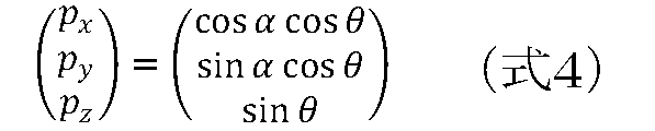
- the zenith angle ⁇ is obtained by substituting the degree of polarization ⁇ obtained by Expression 2 into either ⁇ s or ⁇ d of Expression 3. Based on the azimuth angle ⁇ and the zenith angle ⁇ thus obtained, the normal vector (p x , py , p z ) is obtained as follows.
- the means for observing the polarization luminance is not limited to a linear polarizing plate.
- a polarizer layer may be provided as a part of the imaging device structure.
- FIG. 6 shows an example of the structure of an imaging device having a polarizer layer, which can be introduced into the imaging device 12 of the present embodiment.
- FIG. 1 schematically shows the functional structure of the element cross section, and detailed structures such as an interlayer insulating film and wiring are omitted.
- the imaging device 110 includes a microlens layer 112, a wire grid polarizer layer 114, a color filter layer 116, and a light detection layer 118.
- the wire grid polarizer layer 114 includes a polarizer in which a plurality of linear conductor members are arranged in stripes at intervals smaller than the wavelength of incident light.
- the polarization component in the direction parallel to the polarizer line is reflected, and only the vertical polarization component is transmitted.
- a polarized image is obtained by detecting the transmitted polarized light component with the light detection layer 118.
- the light detection layer 118 has a semiconductor device structure such as a general CCD (Charge Coupled Device) image sensor or a CMOS (Complementary Metal Oxide Semiconductor) image sensor.
- the wire-grid polarizer layer 114 includes an arrangement of polarizers in which the polarization direction in which the charges are read in the photodetection layer 118, that is, in units of pixels or larger, is different.
- the right side of the drawing illustrates a polarizer array 120 when the wire grid type polarizer layer 114 is viewed from above.
- the shaded lines are conductors (wires) constituting the polarizer. Note that the dotted rectangles each represent a region of the polarizer in one direction, and the dotted lines themselves are not actually formed.
- polarizers in four directions are arranged in four regions 122a, 122b, 122c, 122d in two rows and two columns.
- polarizers on diagonal lines have orthogonal transmission directions, and adjacent polarizers have a difference of 45 °. That is, polarizers in four directions at 45 ° intervals are provided.
- An image sensor that simultaneously obtains polarization information in four directions as two-dimensional data by connecting a predetermined number of such polarizer arrays in the vertical and horizontal directions and connecting a peripheral circuit that controls the timing of charge reading. Can be realized.
- a color filter layer 116 is provided between the wire grid polarizer layer 114 and the light detection layer 118.
- the color filter layer 116 includes, for example, an array of filters that respectively transmit red, green, and blue light corresponding to each pixel.
- polarization information is obtained for each color in accordance with a combination of the direction of the polarizer in the wire grid polarizer layer 114 located above and below and the color of the filter in the color filter layer 116. That is, since polarization information of the same direction and the same color is discretely obtained on the image plane, a polarization image of each direction and each color can be obtained by appropriately interpolating the polarization information.
- a non-polarized color image can be reproduced by calculating polarized images of the same color.
- An image acquisition technique using a wire grid polarizer is also disclosed in, for example, JP-A-2012-80065.
- the color filter layer 116 can be omitted if a color image is not required for other uses.
- the polarizer is not limited to the wire grid type, and a linear dichroic polarizer or the like can be used.
- the polarization characteristics of light reflected on the surface of a subject or inside thereof include information on the inclination of the subject surface with respect to the imaging surface and, consequently, the shape and posture of the subject, general polarization information representing the color information of the subject is used.
- Transparent objects are easier to detect than color images.
- the polarization depends on the angle of the photographing viewpoint with respect to the transparent object. In some cases, a transparent object may be difficult to detect.
- FIG. 7 is a diagram for explaining a phenomenon in which the detection accuracy of a subject is reduced depending on the angle of a shooting viewpoint with respect to a transparent object.
- (A) and (b) show a state in which the imaging device 12 is looking down on a state in which a planar object 150a and a cylindrical object 150b are imaged, respectively. It should be noted that the solid line and the dotted line are used for the purpose of explanation and the actual surface is assumed to be uniform.
- the polarization brightness of the light beam from each position on the surface to the imaging device 12 is obtained as a pixel value. For example, looking at the observation points 152a and 152b, while the normal vectors n1 and n2 are in the same direction, the angles of the light rays incident on the imaging device 12 are different.
- the angle ⁇ 1 between the normal vector n1 and the light ray at the observation point 152a having a large angle with respect to the optical axis o of the imaging device 12 is different from the normal vector n2 at the observation point 152b with a small angle with respect to the optical axis o. It becomes larger than the angle ⁇ 2 formed by the light rays.
- the angles ⁇ 1 and ⁇ 2 are nothing but the zenith angles of the normal vectors n1 and n2 at the observation points 152a and 152b.
- the Brewster angle at which the reflectance of p-polarized light becomes zero and only s-polarized light becomes all polarized light is about 56 ° (0.98 rad). Therefore, when the polarization image is analyzed as described above, a high degree of polarization is obtained at the observation point 152a, whereas the degree of polarization is low at the observation point 152b, making it difficult to obtain an appropriate normal vector. As a result, the portion shown by the solid line in the planar object 150a is detected, but the portion shown by the dotted line is not detected.
- the detection accuracy actually deteriorates closer to the position intersecting the optical axis o of the imaging device 12 on the surface of the subject 150a.
- the angle ⁇ 3 between the normal vector n3 and the light beam at the observation point 152c at a large angle from the optical axis o of the imaging device 12 is equal to the normal vector n4 and the light beam at the observation point 152d at a small angle from the optical axis o. It becomes larger than the angle ⁇ 4.
- FIG. 8 shows an internal circuit configuration of the information processing apparatus 10.
- the information processing apparatus 10 includes a CPU (Central Processing Unit) 23, a GPU (Graphics Processing Unit) 24, and a main memory 26. These components are interconnected via a bus 30.
- the bus 30 is further connected to an input / output interface 28.
- the input / output interface 28 includes a peripheral device interface such as USB and IEEE1394, a communication unit 32 including a wired or wireless LAN network interface, a storage unit 34 such as a hard disk drive and a non-volatile memory, a control mechanism of the robot 4, and a control mechanism (not shown).
- An output unit 36 that outputs data to a display device or the like, an input unit 38 that inputs data from the imaging device 12 or an input device (not shown), and a recording medium driving unit 40 that drives a removable recording medium such as a magnetic disk, an optical disk, or a semiconductor memory are included. Connected.
- the CPU 23 controls the entire information processing apparatus 10 by executing an operating system stored in the storage unit 34.
- the CPU 23 also executes various programs read from the removable recording medium and loaded into the main memory 26 or downloaded via the communication unit 32.
- the GPU 24 has a function of a geometry engine and a function of a rendering processor, performs a drawing process according to a drawing command from the CPU 23, and stores display image data in a frame buffer (not shown).
- the main memory 26 is constituted by a RAM (Random Access Memory) and stores programs and data necessary for processing. Note that, as described above, the present embodiment has various applications. Therefore, a part of the illustrated configuration may be omitted or replaced with another circuit depending on the output form of the processing result according to the application.
- FIG. 9 shows a configuration of functional blocks of the information processing apparatus 10 according to the present embodiment.
- each element described as a functional block that performs various processes can be constituted by main circuits such as the CPU 23, the GPU 24, and the main memory 26 shown in FIG. Is realized by a recording medium driven by the recording medium driving unit 40, a program loaded from the storage unit 34 to the main memory 26, and the like. Therefore, it is understood by those skilled in the art that these functional blocks can be realized in various forms by only hardware, only software, or a combination thereof, and the present invention is not limited to any of them.
- the information processing apparatus 10 includes an image acquisition unit 50 that acquires data of a captured image from the imaging device 12, an image data storage unit 52 that stores data of the acquired image, an image analysis unit 54 that performs image analysis including detection of a subject, And an output data generation unit 56 that generates data to be output using the analysis result.
- the image acquisition unit 50 is realized by the input unit 38, the CPU 23, and the like in FIG. 8, and acquires data of a captured image including a polarization image from the imaging device 12.
- polarization images data of polarization images in three directions corresponding to at least transmission axes in three directions are acquired.
- the polarized image may be taken each time the linear polarizing plate 70 disposed on the front surface of the imaging device 12 is rotated as shown in FIG. 2 and stopped in a predetermined direction, or the image sensor having the structure shown in FIG.
- the image may be captured by introducing an image sensor including. In the latter case, a polarization image in a plurality of directions can be acquired by one photographing.
- the image acquisition unit 50 may further acquire general color captured image data.
- the captured image to be obtained may be a moving image or a still image.
- the imaging device 12 is a stereo camera including two cameras provided at a known interval
- the image acquisition unit 50 may acquire data of a stereo image having parallax on the left and right taken by those cameras. .
- the image acquisition unit 50 sequentially stores the acquired captured image data in the image data storage unit 52.
- the image analysis unit 54 is realized by the CPU 23, the GPU 24, and the like in FIG. 8, and performs image analysis including detection of a subject using data stored in the image data storage unit 52. More specifically, the image analysis unit 54 includes a normal line acquisition unit 58, a surface assumption unit 60, and a subject detection unit 62.
- the normal obtaining unit 58 derives the normal vector of the subject by using the change in the polarization luminance with respect to the change in the azimuth as described above. Specifically, first, luminance is extracted for each corresponding pixel of the polarization image in a plurality of directions, and a change in luminance with respect to the polarization direction is derived.
- the polarization image has three directions of ⁇ 1, ⁇ 2, and ⁇ 3, a curve passing through the three points of the coordinates ( ⁇ 1, I1), ( ⁇ 2, I2), and ( ⁇ 3, I3) is calculated by using the least square method or the like.
- a continuous function as shown in FIG. 4 is obtained.
- the maximum luminance I max and the minimum luminance I min are obtained, and the degree of polarization ⁇ and the normal vector are obtained by Expressions 2 to 4.
- the normal line acquisition unit 58 may separately detect a subject based on color information of an image.
- the color information may be obtained by averaging the brightness of the polarization image in a plurality of directions for each corresponding pixel or each color, or may use an image of natural light captured in the corresponding field of view.
- Existing technology can be used for object detection using color information.
- the normal vector may not be obtained or the accuracy of the normal vector may be reduced in a partial area of the subject, depending on the positional relationship and the angle with the imaging device 12. In the case of a transparent object, accurate detection is difficult even with color information.
- the surface assumption unit 60 assumes the existence of a surface in view of the continuity of the subject surface using the distribution of the normal vector acquired by the normal acquisition unit 58. At this time, the surface assumption unit 60 may assume a more likely surface based on separately acquired spatial information such as the position of the light source and the type of object in the object space. A specific example will be described later.
- the subject detection unit 62 confirms whether or not the surface assumed by the surface assumption unit 60 actually exists, and derives a final detection result according to the result.
- confirmation means (1) a mode in which the imaging device 12 is moved to an appropriate position and imaging is performed again, (2) a mode in which the relationship between s-polarized light and p-polarized light is evaluated based on the assumed normal to the plane, and (3) imaging A mode in which a change in an image when the device 12 is moved is confirmed may be considered.
- the information finally derived by the subject detection unit 62 is not limited to the distribution of normal vectors. For example, it may only indicate that the surface exists at the assumed position, or may generate data representing the position and orientation of the subject based on the normal vector distribution.
- the output data generation unit 56 is realized by the CPU 23, the GPU 24, the output unit 36, and the like in FIG. 8, performs predetermined information processing based on the information specified by the image analysis unit 54, and outputs a control signal to the robot, a display image, Generates and outputs data to be output such as voice.
- the content of the information processing performed here and the type of output data are not particularly limited. For example, if it is determined that a glass window is present in front of the robot, a control signal for changing direction may be transmitted, or a control signal for grasping a subject including a detected transparent object may be transmitted. Good.
- an image or a sound indicating the presence of the object or the object may be generated and output to the display device.
- a display image representing virtual reality or augmented reality may be generated by replacing a detected subject with a virtual object, and output to a display device.
- the virtual object may be drawn so as to match the shape and posture of the subject.
- the image acquisition unit 50 acquires the data of the stereo image
- the distance to the subject may be obtained using the data and reflected in the output data.
- the information of the normal vector acquired by the image analysis unit 54 may be integrated with the thus obtained distance information for each corresponding point to acquire more detailed distance information.
- the output data generation unit 56 also outputs information necessary for confirming the existence of the surface assumed by the subject detection unit 62. Specifically, a control signal for moving the imaging device 12 to an appropriate position for photographing is generated and transmitted to the robot 4. Alternatively, an image or sound for instructing the user who has mounted or held the imaging device 12 the moving direction and the imaging timing may be generated and transmitted to the display device or the speaker.
- FIG. 10 is a diagram for explaining a method in which the surface assumption unit 60 assumes the surface of the subject.
- the surfaces 160a and 160b of the subject are detected and the normal vectors n1 and n2 are obtained.
- regions where the degree of polarization greater than a preset threshold is obtained are defined as "detected" surfaces 160a and 160b.
- the surface assumption unit 60 evaluates the possibility that a surface exists in the region 162 therebetween.
- the presence of a surface obtained by extending the detected surfaces 160a and 160b in a direction in which the angle formed with the optical axis o of the imaging device 12 is small is estimated.
- the shape of the surface can be assumed by interpolating the distribution of the normal vector by a known calculation method.
- the existence of the surface may be assumed.
- At least one of the image distortion 164 and the specular highlight 166 in the color image may be confirmed to estimate the existence of the surface and its shape.
- the estimation using the image distortion 164 for example, by estimating the state of the partial distortion 168 of the image 167 of one subject from a portion having no distortion, the state is transparent over the region 162 in front of the subject. Presume that an object exists.
- the shape of the surface is estimated from the degree of distortion.
- the type of an object such as a television or a table
- the presence or absence of distortion and the shape may be estimated by taking a difference from the original shape.
- a database may be prepared in advance in which the type of the object or the color or size for deriving the type is associated with the original shape.
- An object provided in the space, such as a television or a table, may be photographed in advance, and image distortion may be detected based on a difference from an image photographed during operation.
- the specular highlight 166 As an estimation using the specular highlight 166, when an image (highlight) 170 of a strong reflected light whose luminance is equal to or more than a threshold value is detected in the region 162, it is estimated that there is a surface there.
- the position of the light source 172 with respect to the imaging device 12 in the real space may be separately acquired, and the shape of the surface may be estimated based on the relationship between the shape and size of the highlight 170.
- a technique for drawing a highlight with the position of a light source and the shape of an object known is widely known in the field of computer graphics.
- the shape of the subject can be obtained by an inverse operation.
- Such a technique is known as inverse rendering.
- the position of the light source can be obtained by at least one of the following methods. 1. 1. Shoot the light source itself 2. Place a sphere of the color or material reflected by the light source in the subject space. 3. Use specular highlights on a subject whose shape is known Utilizing the reflection in the eyes of people in the subject space
- No. 2 is a technique in which a user sets a sphere in which a light source is reflected in a subject space at the start of information processing, and acquires the position of the light source based on an image on a spherical surface. For example, when the sphere is made of a material like a mirror, the image of the light source can be clearly displayed.
- # 3 is a method that uses an object of a known shape that is specularly reflected and that exists in the object space instead of the silver sphere. For example, if a specular highlight is observed in a region other than the region 162 in the captured image, the three-dimensional shape of the object causing the highlight is specified. Then, the position of the light source is specified based on the shape and position of the highlight.
- a database in which the two are associated with each other may be used as described above.
- the image may be shown to the user via the display device, and the type and shape of the object may be input.
- # 4 is a technique that uses a human eyeball instead of those objects.
- a human face is detected from the captured image by the existing technology, and the position of the light source is identified from the highlight in the image of the pupil.
- the position of the light source can be more easily acquired.
- the surface assumption unit 60 assumes the surface 164 in the undetected region 162 and its normal vector by at least one of the means described above.
- FIG. 11 is a diagram for explaining a method in which the subject detection unit 62 moves the imaging device 12 to confirm the existence of an assumed surface.
- This figure shows the same case as shown in FIG. That is, it is assumed that the surface 160a including the observation point 152a and the surface 160b are detected from the captured image at the position of the imaging device 12a, and the existence of a plane following them is assumed between them.
- the subject detection unit 62 moves the imaging device 12 to a position and an orientation at which a degree of polarization larger than the threshold is obtained with respect to the assumed plane, and guides the robot or the user to take an image again.
- the imaging device 12a is moved to the position of the imaging device 12b.
- the angle ⁇ 5 between the light ray from the observation point 152b and the normal line n2 increases, and the degree of polarization also increases.
- a normal vector can be obtained with high accuracy. That is, the subject detection unit 62 moves the imaging device 12 to a position and an orientation in which the angle ⁇ between the normal vector at each assumed position on the plane and the light beam therefrom falls within a predetermined range. For example, when it is desired to obtain a polarization degree of about 0.5 or more, the imaging device 12 may be moved so that 0.6 rad ⁇ ⁇ 1.3 rad.
- the movement and imaging of the imaging device 12 are repeated a plurality of times to acquire the degree of polarization and the normal vector.
- the movement and photographing of the imaging device 12 may be realized by the subject detection unit 62 transmitting a control signal to the robot 4 via the output data generation unit 56, or may be realized by an image or sound indicating a movement direction or a photographing timing. May be transmitted to the display device and presented to the user.
- FIG. 12 shows a state in which the imaging device 12 is moved for various object shapes to detect a surface.
- (A) targets the cylindrical object 150b shown in (b) of FIG.
- the surfaces 174a and 174b are detected based on the captured image from the position of the imaging device 12c.
- the surface assumption unit 60 assumes the existence of a plane following them as shown by the dotted line.
- the subject detection unit 62 moves the imaging device 12 to a position and a direction in which the angle between the normal vector at each assumed position on the plane and the light ray therefrom falls within a predetermined range.
- an undetected surface is detected as shown in gray.
- the entire surface of the cylindrical object 150b can be detected.
- FIG. (B) schematically shows an object 150c having an arbitrary shape.
- the surface 174c is detected based on a captured image from the position of the imaging device 12e.
- the surface assumption unit 60 assumes the presence of a subsequent plane as indicated by a dotted line.
- the subject detection unit 62 moves the imaging device 12 to a position and a direction in which the angle between the normal vector at each assumed position on the plane and the light ray therefrom falls within a predetermined range.
- the undetected surface is detected as shown in gray.
- the entire surface of the subject 150c having an arbitrary shape can be detected.
- FIG. 13 is a diagram for explaining another method of confirming the existence of an assumed surface by moving the imaging device 12 by the subject detection unit 62.
- a moving image is shot while changing the angle with respect to the surface 176 assumed by the surface assumption unit 60.
- an image is captured on an arc centered on at least one of the positions 178 of the surface 176 while moving the imaging device 12 within a range of a predetermined angle ⁇ c from the normal vector n, that is, an angle 2 ⁇ c.
- the object in front of the specular reflection is captured while the angle between the optical axis and the surface is small, and when the angle approaches 90 °, the transmitted light causes Changes in the image such as objects behind the scene are likely to occur.
- the subject detection unit 62 transmits a control signal to the robot 4 via the output data generation unit 56 to move the imaging device 12 so as to change the angle with respect to the surface, and to shoot a moving image.
- an image or sound for instructing the user to do so is generated and transmitted to the display device.
- the image obtaining unit 50 obtains data of a moving image captured accordingly.
- the subject detection unit 62 acquires a snapshot of the captured image at the start point of the movement in the moving image. If a transparent object exists on the surface 176, there is a high possibility that the image of "Scene A" on the near side is reflected on the surface due to reflection. Then, if the image reflected on the surface 176 changes in the process of moving the imaging device 12, it is an image transmitted through “Scene B” behind the surface 176, and the state transition from reflection to transmission may have occurred. Is high. Therefore, at this point, it can be determined that a transparent object exists on the surface 176. When the imaging device 12 is further moved and “Scene A” is again displayed, a state transition from transmission to reflection has occurred, and the probability that a transparent object exists on the surface 176 is further increased.
- the change of the image can be determined by comparing with the snapshot acquired first. That is, if a change other than the change in the angle of view is obtained for the snapshot, it can be determined that the reflection has changed the image from scene A to scene B. If no change other than the change in the angle of view is observed even when the imaging device 12 is moved, it is concluded that the assumed surface 176 has no transparent object.
- This mode is based on the existence of a transparent object by intentionally creating a state in which an object in front is reflecting.
- the image to be used may be a polarization image or a color image.
- FIG. 14 is a diagram for explaining a method in which the subject detection unit 62 evaluates the ratio of s-polarized light and p-polarized light to confirm the existence of an assumed surface.
- the state of the object and the light source on the background of the assumed surface is known.
- an indoor state where no transparent object or the like is placed is photographed in advance, and the color, shape, size, position of the light source, and the like of the surrounding objects are acquired.
- (A) of the figure shows a case where a black object, that is, an object 182 whose albedo is lower than a predetermined value exists as a background of the assumed plane 180. In this case, if there is a transparent object on the assumed surface 180, light that is specularly reflected on the surface 180 mainly enters the imaging device 12.
- specular reflection light is dominated by s-polarized light.
- the object 182 is originally formed of a material in which diffuse reflection is dominant, and mainly p-polarized light should be observed.
- a transparent object is placed in front of the object 182. It can be determined that it exists. According to the same theory, even when the background of the assumed surface 180 is dark, if s-polarized light is mainly observed, it can be determined that there is a transparent object such as a glass window there.
- s-polarized light is light that oscillates perpendicularly to the plane of incidence, so if the polarization direction giving the maximum luminance is shifted by 90 ° with respect to the plane of incidence obtained from the normal to the estimated plane, then the s-polarized light will be It is concluded that it is superior.
- (B) shows a case where natural light such as ambient light is dominant as the background of the assumed plane 180. In this case, if there is a transparent object on the assumed surface 180, light transmitted through the surface 180 mainly enters the imaging device 12. Even if natural light originally has a degree of polarization close to 0, p-polarized light becomes dominant partial polarized light by transmitting through a transparent object.
- FIG. 14 assumes a case where there is a difference between the reflection characteristic originally possessed by the object behind and the polarization state due to the reflected light or transmitted light when there is a transparent object, and makes use of the difference to make the transparent state. The presence or absence of the object was determined. On the other hand, if the reflected light and the transmitted light from the same transparent object are simultaneously observed, the presence or absence of the transparent object can be determined without limiting the material of the object behind.
- FIG. 15 is a diagram for explaining a method of determining the presence or absence of a transparent object in an environment where reflected light and transmitted light can be observed simultaneously.
- the upper part of the figure shows the background 190 and a flat transparent object 192 in front of the background 190 as the subject.
- the upper half is white (for example, there is an object whose albedo is higher than a predetermined value) and the lower half is black (for example, there is an object whose albedo is lower than a predetermined value).
- uniform light is emitted from the imaging device 12 side.
- the lower part of the figure shows a color image 194 of the state captured by the imaging device 12, a distribution 196 of the degree of polarization corresponding to the plane of the image, and a distribution 198 of the polarization (p-polarized light / s-polarized light).
- the boundaries of the regions corresponding to the transparent objects 192 are indicated by dotted lines.
- the degree of polarization is large in the region 202 where the light reflected by the transparent object 192 reaches, and the degree of polarization is smaller in the region 200 where the light transmitted through the transparent object 192 reaches. This is because, as shown in FIG. 5, the degree of polarization of specular reflection is larger than the degree of polarization of diffuse reflection regardless of the zenith angle.
- the degree of polarization is further reduced.
- the polarization distribution 198 the p-polarized light becomes dominant in the region 200 where the light transmitted through the transparent object 192 reaches, and the s-polarized light becomes dominant in the region 202 where the light reflected from the transparent object 192 reaches. .
- the ratio of p-polarized light to s-polarized light is difficult to be clear because the degree of polarization is small.
- the degree of polarization is higher than the predetermined value and p-polarization is dominant.
- the luminance value is lower than the predetermined value.
- the degree of polarization is higher than a predetermined value, and s-polarized light is dominant.
- the “predetermined values” that are the reference values for the luminance value and the degree of polarization in (1) and (2) are all independent. May be set to Then, when the above (1) and (2) are simultaneously satisfied, it is determined that the transparent object 192 is present.
- the difference in albedo in the background may be prepared by using an object whose area is clearly divided as shown in the figure, or by using a table in which the albedo is higher than a predetermined value and an object in a subject space such as a television in which the albedo is lower than a predetermined value. May be used. There may be a part with illumination and a part in darkness.
- the subject detection unit 62 captures the high and low albedo portions of the object in the background in the area where the surface is assumed by the surface assumption unit 60, and obtains a degree of polarization equal to or more than a predetermined value. It is desirable to adjust the position and orientation of the imaging device 12.
- FIG. 16 shows another example of determining the presence or absence of a transparent object in an environment where reflected light and transmitted light of the transparent object can be observed simultaneously.
- the background 210 and the cylindrical transparent object 212 in front thereof are photographed.
- the environment of the background 210 and the light source is the same as in the case of FIG.
- the lower part of the figure shows the color image 214 taken at that time, the distribution 216 of the degree of polarization corresponding to the plane of the image, and the distribution 218 of the polarized light (p-polarized light / s-polarized light).
- the color image 214 reflects the background 210, and an image in which the upper half is white and the lower half is black is obtained.
- the degree of polarization is large in a part area 220 of the area where the light reflected by the transparent object 212 reaches, and in a part area 222 of the area where the light transmitted through the transparent object 212 reaches.
- the degree is smaller than the area 220. In other areas, the degree of polarization further decreases. The reason why the degree of polarization is increased only in a part of the region where the reflected or transmitted light reaches is because there is a dependence on the zenith angle as shown in FIG.
- the width of the reflected light region 220 is wider than that of the transmitted light region 222, as shown in FIG. However, this is because the range in which a high degree of polarization can be obtained is wide.
- the p-polarized light is dominant in a part of the region 222 where the light transmitted through the transparent object 212 reaches, and the part of the region 220 where the light reflected from the transparent object 212 reaches In, s-polarized light becomes dominant.
- the ratio of p-polarized light to s-polarized light is difficult to be clear because the degree of polarization is small.
- one of the following two conditions is used. (1) In a region where the luminance value is higher than a predetermined value in a color image (eg, a white region), there is a region having a predetermined shape in which the degree of polarization is higher than the predetermined value and p-polarization is dominant. In a region lower than the predetermined value (eg, a black region), there is a region having a predetermined shape in which the degree of polarization is higher than the predetermined value and s-polarized light is dominant.
- all of the “predetermined values” serving as references for the luminance value and the degree of polarization in (1) and (2) may be set independently of each other.
- the “predetermined shape” is defined in advance based on the assumed shape of the transparent object.
- the aspect ratio has a rectangular or substantially rectangular shape satisfying a predetermined condition.
- the direction of the cylinder is determined by the direction of the region. Also in this mode, it is desirable that the subject detection unit 62 adjusts the position and orientation of the imaging device 12 so that the high albedo portion and the low albedo portion of the object in the background are captured.
- FIG. 17 is a flowchart illustrating a procedure of a process in which the information processing apparatus 10 detects a subject using a captured image.
- This flowchart starts in a state where the imaging device 12 is capturing an image of the object space including the polarization image.
- the image acquisition unit 50 of the information processing device 10 acquires data of a captured image including a polarization image (S10).
- the normal line acquisition unit 58 of the image analysis unit 54 detects a subject by a general method using at least the polarization image (S12). Specifically, the distribution of the degree of polarization and the distribution of the normal vector are obtained based on the luminance characteristics of the polarized image by the above-described procedure.
- the normal line acquiring unit 58 may extract a region of the subject image based on the color information using the color image. Further, the distance to the subject may be obtained using a stereo image.
- the surface assumption unit 60 assumes that there is a surface extending from the surface detected in S10 in a direction in which the angle with respect to the optical axis of the imaging device 12 decreases (S14). Specifically, as described above, when a predetermined condition that can determine that there is continuity is satisfied for the distribution of the degree of polarization and the normal vector, the distance to the subject, the image of a surrounding object such as a frame, and the like, undetected It is determined that there is a high probability that a certain surface exists.
- the surface assumption unit 60 estimates the normal vector of the assumed surface (S16). For this processing, the image distortion and the position and shape of the specular highlight shown in FIG. 10 are used. Alternatively, the normal vector of the detected surface may be interpolated.
- the subject detection unit 62 checks whether or not the assumed surface actually exists (S18). That is, the position and orientation of the imaging device 12 are changed, and an attempt is made to obtain a normal vector by using a plurality of azimuthally polarized images captured again within a range in which a degree of polarization larger than the threshold is obtained.
- the subject detection unit 62 determines whether or not a surface actually exists on the assumed surface by at least one of these methods. Note that if the normal vector of the transparent object is obtained by interpolation processing or the like in S18, the normal vector estimated in S16 may not be strict.
- the output data generation unit 56 performs predetermined information processing based on the determined result, that is, the presence of the entire subject, its position, posture, distribution of normal vectors, and the like, and generates the result as output data. And output to a display device as appropriate (S20). If it is not necessary to stop the processing due to a request from the user (N of S22), the processing from S10 to S20 is repeated. The entire process is terminated as necessary to stop the process (Y in S22).
- the normal vector of the object is obtained using the polarization image.
- an object having a high light transmittance that is difficult to detect in a general color image can be detected without omission, and the detection result can be used for information processing without limiting the type of the object.
- accuracy and versatility of, for example, robot control, electronic content processing, inspection processing, and monitoring can be improved.
- 10 information processing device 12 imaging device, 23 CPU, 24 GPU, 26 main memory, 50 image acquisition unit, 52 image data storage unit, 54 image analysis unit, 56 output data generation unit, 58 normal line acquisition unit, 60 surface assumption , ⁇ 62 ⁇ subject detection unit.
- the present invention can be used for various information processing devices and systems such as a robot control device, an electronic content processing device, a portable terminal, a surveillance camera system, and an inspection device.
Landscapes
- Engineering & Computer Science (AREA)
- Physics & Mathematics (AREA)
- General Physics & Mathematics (AREA)
- Theoretical Computer Science (AREA)
- Multimedia (AREA)
- Computer Vision & Pattern Recognition (AREA)
- Artificial Intelligence (AREA)
- Geometry (AREA)
- Image Analysis (AREA)
- Investigating Or Analysing Materials By Optical Means (AREA)
- Length Measuring Devices By Optical Means (AREA)
Abstract
情報処理装置10の画像取得部50は、複数方位の偏光画像を撮像装置12から取得する。画像解析部54の法線取得部58は、偏光輝度の方位依存性に基づき法線ベクトルを取得することで被写体の面を検出する。表面仮定部60は検出された面と連続し、検出されていない面の存在を仮定する。被写体検出部62は仮定された面に推定される法線ベクトルを利用して仮定された面の有無を確認する。出力データ生成部56は検出された面の情報を用いて出力データを生成し出力する。
Description
本発明は、撮影画像を利用して実物体を検出する情報処理装置および物体検出方法に関する。
ユーザの頭部など体の一部をビデオカメラで撮影し、目、口、手などの所定の領域を抽出して別の画像で置換した表示画像を利用するゲームが知られている(例えば、特許文献1参照)。また、ビデオカメラで撮影された口や手の動きをアプリケーションの操作指示として受け取るユーザインタフェースシステムも知られている。このように、実世界を撮影して対象物の状態を検知したり、それに基づく情報処理を実施したりする技術は、電子コンテンツのみならず、自動制御ロボット、監視カメラ、自動運転システム、製造ラインにおける検品装置など幅広い分野で導入されている。
撮影画像における被写体の像の様子は、周囲の明るさや物の数、配置などによる光の状態の変化に影響される。そのため同じ被写体でも、その像の色や輝度分布が大きく変化したり、輪郭が明確に得られなかったりした結果、検出に失敗したり他の物と混同したりすることが起こり得る。特に無色のガラスやアクリル樹脂など、光線透過率が高い材質の物は色情報に乏しく、また周囲の状況の影響を受けやすいため安定的な検出が難しい。
本発明はこうした課題に鑑みてなされたものであり、その目的は、光線透過率の高い物であっても、撮影画像を用いた物体検出を安定的に実現できる技術を提供することにある。
本発明のある態様は情報処理装置に関する。この情報処理装置は、複数の方位の偏光画像のデータを撮像装置から取得する画像取得部と、偏光画像を用いて法線ベクトルを取得することにより被写体の面を検出する法線取得部と、検出された面から連続する、検出されていない面の存在を仮定する表面仮定部と、仮定された面に推定される法線ベクトルを利用して、当該面の有無を確認し最終的な被写体の面を導出する被写体検出部と、導出された被写体の面に係る情報に基づき出力データを生成し出力する出力データ生成部と、を備えたことを特徴とする。
本発明のさらに別の態様は物体検出方法に関する。この物体検出方法は情報処理装置が、複数の方位の偏光画像のデータを撮像装置から取得するステップと、偏光画像を用いて法線ベクトルを取得することにより被写体の面を検出するステップと、検出された面から連続する、検出されていない面の存在を仮定するステップと、仮定された面に推定される法線ベクトルを利用して、当該面の有無を確認し最終的な被写体の面を導出するステップと、導出された被写体の面に係る情報に基づき出力データを生成し出力するステップと、を含むことを特徴とする。
なお、以上の構成要素の任意の組合せ、本発明の表現を方法、装置などの間で変換したものもまた、本発明の態様として有効である。
本発明によると、光線透過率の高い物であっても、撮影画像を用いた物体検出を安定的に実現できる。
本実施の形態は、撮像装置が撮影した画像を解析することにより、空間に存在する物を検出したり、その位置や姿勢を認識したりすることを基本とする。その限りにおいて、検出結果をどのように利用するかは特に限定されない。図1は、本実施の形態における情報処理システムの構成例を示している。図示する例では、撮像装置12を装備したロボット4が周囲に存在する物体8a、8b、8cを認識しながら歩行することを想定している。ロボット4の内部には、撮影画像を解析し、物体8a、8b、8cの形状、距離、姿勢などを認識してロボット4を好適に動作させる情報処理装置10が備えられる。
このような形態はV-SLAM(Visual Simultaneous Localization and Mapping)を導入した自動制御ロボットや無人搬送車などで広く知られている。ただし情報処理装置10は外部からロボット4を遠隔制御する装置としてもよい。また情報処理装置10が、物体の検出結果を図示しない表示装置に表示させ、ユーザがそれを見ながら、図示しない入力装置を用いてロボット4を遠隔操作する態様としてもよい。一方、ロボット4の代わりにユーザが、撮像装置12を備えたヘッドマウントディスプレイを装着する態様としてもよい。
この場合、情報処理装置10を、ヘッドマウントディスプレイに内蔵させてもよいし、ヘッドマウントディスプレイと無線あるいは有線により通信接続可能な外部の装置としてもよい。このとき情報処理装置10は、物体の検出結果に基づき表示画像を生成し、それをヘッドマウントディスプレイに表示させてもよい。当該表示画像の少なくとも一部は、撮像装置12が撮影した画像であってもよい。撮像装置12をユーザが把持し、情報処理装置10がその撮影画像を無線または有線により取得し解析してもよい。
撮像装置12、情報処理装置10、および図示しない表示装置を一体的に備える携帯端末をユーザが把持してもよい。情報処理装置10を採用できる形態は、ロボットの制御システム、電子コンテンツ処理装置、監視カメラシステム、検品装置など様々に考えられる。そのため情報処理装置10から出力される情報も、ロボット4への制御信号、表示画像、出力音声など、目的によって変化し得る。
これらの技術においては、物体8a、8b、8cや、その周囲の状況をできるだけ正確に特定する必要がある。しかしながら一般的なカラーの撮影画像では、ガラスやアクリル樹脂など光線透過率の高い材質の物が像として写りにくい。そのため、そのような材質の物を認識しなかったり、光線の具合によって背後や手前にある別の物を、そこにあるように誤認識したりすることが考えられる。そこで本実施の形態では、撮像装置12により被写空間の偏光を観測し、偏光の特性を利用して、光線透過率の高い材質の物を精度よく検出できるようにする。
ここで「光線透過率の高い材質」は、例えば無色のガラスやアクリル樹脂などであるが、対象とする光線透過率や色は限定されない。すなわち一般的なカラーの撮影画像を用いては見過ごされやすい物も網羅して検出できるようにすることで、全体として撮影による誤認識の発生を抑えることを旨とし、検出対象を限定する趣旨ではない。以後、「光線透過率の高い材質」で形成された物体を「透明物体」と呼ぶ。
図2は、本実施の形態で利用する偏光の基本的な特性を説明するための図である。撮像装置12は、直線偏光板70を介して被写体72を含む空間を撮影する。より詳細には撮像装置12は、光源から照射された光が被写体72を反射してなる鏡面反射成分と、被写体72内部で散乱された光が表面から出射してなる拡散反射成分とで構成される反射光のうち、直線偏光板70によって定まる方向に振動する偏光を観測する。被写体72の表面のうち観測点aにおける法線ベクトルnと、点aから画像平面80上の結像点bに到達する光線82を含む面を、観測点aにおける入射面76と呼ぶ。
直線偏光板70は、光線82のうちある方向に振動する直線偏光のみを透過する。以後、透過させる偏光の振動方向を直線偏光板70の透過軸と呼ぶ。直線偏光板70を面に垂直な軸周りに回転させれば、透過軸を任意の方向にとることができる。仮に撮像装置12へ到達する光が無偏光であれば、直線偏光板70を回転させても、観測される輝度は一定となる。一方、一般的な反射光は部分偏光により、透過軸の方向に対し観測される輝度に変化が生じる。また鏡面反射と拡散反射の割合や入射角によって、輝度の変化の様子が異なる。
図3は、入射角に対する偏光方向の変化を鏡面反射と拡散反射で比較している。ここで「s偏光」は入射面に垂直な方向に振動する成分、「p偏光」は入射面に平行な方向に振動する成分である。鏡面反射および拡散反射の双方において、s偏光とp偏光の割合は入射角に依存する。また鏡面反射の光は、入射角によらずs偏光が支配的である。このため、直線偏光板70の透過軸が入射面と垂直な状態において観測輝度が最大となり、当該透過軸が入射面と平行な状態において観測輝度が最小となる。
拡散反射の光はその逆であり、直線偏光板70の透過軸が入射面と平行な状態において観測輝度が最大となり、当該透過軸が入射面と垂直な状態において観測輝度が最小となる。したがって、様々な透過軸の方向で偏光画像を撮影することにより得られる結像点bの偏光輝度の変化は、入射面76の角度と、入射光(あるいは出射光)の角度、すなわち被写体72上の観測点aにおける法線ベクトルnの天頂角θの情報を含んでいることになる。本実施の形態でもこのような偏光の輝度の変化を利用する。
図4は、偏光方位φに対する輝度Iの変化を例示している。同図上段は鏡面反射が支配的な場合、下段は拡散反射が支配的な場合であり、どちらも180°周期の正弦波の形状を有する。一方、鏡面反射の輝度Iが最大値Imaxをとるときの偏光方位ψsと、拡散反射の輝度Iが最大値Imaxをとるときの偏光方位ψdには90°の差がある。これは上述したように、鏡面反射においてはs偏光が、拡散反射においてはp偏光が支配的なことに起因する。
s偏光が入射面に垂直、p偏光が入射面に平行な振動であることに鑑みれば、鏡面反射において輝度が最小となる偏光方位(ψs-90°)、あるいは拡散反射において輝度が最大となる偏光方位ψdが、入射面の角度を表す。法線ベクトルnは常に入射面に含まれるため、当該角度は、法線ベクトルnを撮影画像平面に射影したベクトルの角度を表す。この角度は一般的に、法線ベクトルnの方位角と呼ばれる。当該方位角に加え、上述した天頂角を求めることにより、撮像装置12から見た3次元空間での法線ベクトルが一意に定まる。観測される偏光の輝度が最大となるときの偏光方位は位相角ψと呼ばれる。図4で示す輝度Iの変化は、位相角ψを用いて次の式で表すことができる。

直線偏光板70を回転させ複数の偏光方位φに対し観測される輝度を、最小二乗法等を用いて式1の形式に近似することにより、Imax、Imin、ψを求めることができる。そのうちImax、Iminを用いて、次の式により偏光度ρが求められる。

図5は、法線ベクトルの天頂角に対する偏光度の変化の例を、鏡面反射と拡散反射で比較している。上段に示す鏡面反射の場合、偏光度は最大で1.0までの値をとるのに対し、下段に示す拡散反射の偏光度は、最大でも0.4程度である。なお天頂角θは、鏡面反射の場合の偏光度ρs、拡散反射の場合の偏光度ρdと、それぞれ次のような関係にある。
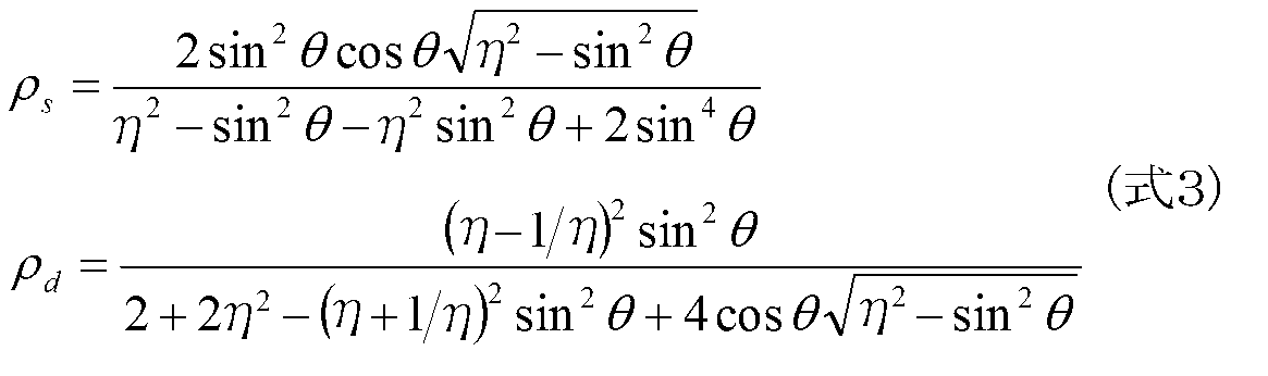
ここでηは物体の屈折率である。式2で得られる偏光度ρを式3のρs、ρdのどちらかに代入することにより天頂角θが得られる。こうして得られた方位角α、天頂角θにより、法線ベクトル(px,py,pz)は次のように得られる。
なお本実施の形態において、偏光輝度を観測する手段は直線偏光板に限らない。例えば撮像素子構造の一部として偏光子の層を設けてもよい。図6は、本実施の形態の撮像装置12に導入できる、偏光子層を備える撮像素子の構造例を示している。なお同図は素子断面の機能的な構造を模式的に示しており、層間絶縁膜や配線などの詳細な構造は省略している。撮像素子110はマイクロレンズ層112、ワイヤグリッド型偏光子層114、カラーフィルター層116、および光検出層118を含む。
ワイヤグリッド型偏光子層114は、複数の線状の導体部材を入射光の波長より小さい間隔でストライプ状に配列させた偏光子を含む。マイクロレンズ層112により集光された光がワイヤグリッド型偏光子層114に入射すると、偏光子のラインと平行な方位の偏光成分は反射され、垂直な偏光成分のみが透過する。透過した偏光成分を光検出層118で検出することにより偏光画像が取得される。光検出層118は一般的なCCD(Charge Coupled Device)イメージセンサやCMOS(Complementary Metal Oxide Semiconductor)イメージセンサなどの半導体素子構造を有する。
ワイヤグリッド型偏光子層114は、光検出層118における電荷の読み取り単位、すなわち画素単位、あるいはそれより大きな単位で透過する偏光方位が異なるような偏光子の配列を含む。同図右側には、ワイヤグリッド型偏光子層114を上面から見たときの偏光子配列120を例示している。同図において網掛けされたラインが偏光子を構成する導体(ワイヤ)である。なお点線の矩形はそれぞれ1方向の偏光子の領域を表しており、点線自体は実際に形成されるものではない。
図示する例では、4方向の偏光子が2行2列の4つの領域122a、122b、122c、122dに配置されている。図中、対角線上にある偏光子はその透過方向が直交しており、隣り合う偏光子は45°の差を有する。すなわち45°おきの4方向の偏光子を設けている。これが直線偏光板70の代わりとなり、下に設けた光検出層118においては、4つの領域122a、122b、122c、122dに対応する各領域で、45°おきの4方位の偏光情報を得ることができる。このような偏光子配列をさらに縦方向、横方向に所定数、配列させ、電荷読み出しのタイミングを制御する周辺回路を接続することにより、4方位の偏光情報を2次元データとして同時に取得するイメージセンサを実現できる。
同図に示す撮像素子110では、ワイヤグリッド型偏光子層114と光検出層118の間にカラーフィルター層116を設けている。カラーフィルター層116は、例えば各画素に対応させて赤、緑、青の光をそれぞれ透過するフィルタの配列を含む。これにより、上下に位置するワイヤグリッド型偏光子層114における偏光子の方向とカラーフィルター層116におけるフィルタの色の組み合わせに応じて、偏光情報が色別に得られる。すなわち同一方位かつ同一色の偏光情報が画像平面上で離散的に得られるため、それを適宜補間することにより、方位ごとおよび色ごとの偏光画像が得られる。
また同一色の偏光画像同士を演算することにより、無偏光のカラー画像を再現することもできる。ワイヤグリッド型偏光子を用いた画像取得技術については、例えば特開2012-80065号公報などにも開示されている。ただし本実施の形態では基本的に偏光輝度画像を用いるため、その他の用途でカラー画像が必要なければカラーフィルター層116を省略することもできる。また偏光子はワイヤグリッド型に限らず、線二色性偏光子などを用いることもできる。
これまで述べたように、被写体表面あるいは内部で反射した光の偏光特性は、被写体表面の撮像面に対する傾き、ひいては被写体の形状や姿勢の情報を含むことから、被写体の色情報を表す一般的なカラー画像と比較し透明物体を検出しやすい。一方、図1で示したように物体8a、8b、8cを任意の視点から撮影する場合、あるいは逆に撮像面に対し物体が動いている場合など、透明物体に対する撮影視点の角度によっては、偏光によっても透明物体が検出しにくいことがある。
図7は、透明物体に対する撮影視点の角度によって被写体の検出精度が低下する現象を説明するための図である。(a)、(b)は撮像装置12がそれぞれ、平面状の被写体150aおよび円筒状の被写体150bを撮影している様子を俯瞰した状態を示している。なお被写体表面を実線と点線としているのは説明のためであり、実際は一様とする。(a)において被写体150aを撮影することにより、表面上の各位置から撮像装置12への光線の偏光輝度が画素値として得られる。例えば観測点152a、152bを見ると、法線ベクトルn1、n2が同じ方向である一方、撮像装置12へ入射する光線の角度が異なる。
具体的には、撮像装置12の光軸oに対する角度が大きい観測点152aにおける、法線ベクトルn1と光線のなす角θ1は、光軸oに対する角度が小さい観測点152bにおける、法線ベクトルn2と光線のなす角θ2より大きくなる。ここで角度θ1、θ2は、各観測点152a、152bにおける法線ベクトルn1、n2の天頂角に他ならない。観測される光は鏡面反射が支配的であるとすると、図5の上段に示すように、天頂角が0.6radから1.3rad程度の範囲で高い偏光度が得られ、天頂角がその範囲から離れるほど偏光度が低くなる。
例えばガラスの場合、p偏光の反射率が0になりs偏光の成分のみの全偏光となるブリュースター角は約56°(0.98rad)である。そのため上述のように偏光画像を解析すると、観測点152aでは高い偏光度が得られるのに対し、観測点152bでは偏光度が低くなり、適正な法線ベクトルが得られにくくなる。結果として、平面状の被写体150aのうち実線で示した部分は検出される一方、点線で示した部分は検出されない。
図5に示したように偏光度は天頂角に対し徐々に変化するため、実際には被写体150aの表面上で、撮像装置12の光軸oと交差する位置に近づくほど、検出精度が悪化していく。(b)に示した円筒状の被写体150bの場合も同様である。すなわち撮像装置12の光軸oからの角度が大きい観測点152cにおける、法線ベクトルn3と光線のなす角θ3は、光軸oからの角度が小さい観測点152dにおける、法線ベクトルn4と光線のなす角θ4より大きくなる。
そのため、観測点152cでは高い偏光度が得られるのに対し、観測点152bでは偏光度が低くなり、法線ベクトルの検出精度が悪化する。結果として円筒状の被写体150bのうち実線で示した部分は検出される一方、点線で示した部分は検出されない。このような現象は、被写体の形状によらず発生し得る。
被写体が透明物体の場合、カラーの撮影画像が示す色情報でも検出が困難なことから、撮影画像からは検出できない部分が発生することになる。そこで本実施の形態では、検出結果が適正に得られている部分から、撮像装置12の光軸oとのなす角度が小さくなる方向に、被写体の面が続いていると仮定したうえ、実際に面が存在するか否かを、偏光を利用して確認することで検出精度を向上させる。
図8は、情報処理装置10の内部回路構成を示している。情報処理装置10は、CPU(Central Processing Unit)23、GPU(Graphics Processing Unit)24、メインメモリ26を含む。これらの各部は、バス30を介して相互に接続されている。バス30にはさらに入出力インターフェース28が接続されている。入出力インターフェース28には、USBやIEEE1394などの周辺機器インターフェースや、有線又は無線LANのネットワークインターフェースからなる通信部32、ハードディスクドライブや不揮発性メモリなどの記憶部34、ロボット4の制御機構や図示しない表示装置などへデータを出力する出力部36、撮像装置12や図示しない入力装置からデータを入力する入力部38、磁気ディスク、光ディスクまたは半導体メモリなどのリムーバブル記録媒体を駆動する記録媒体駆動部40が接続される。
CPU23は、記憶部34に記憶されているオペレーティングシステムを実行することにより情報処理装置10の全体を制御する。CPU23はまた、リムーバブル記録媒体から読み出されてメインメモリ26にロードされた、あるいは通信部32を介してダウンロードされた各種プログラムを実行する。GPU24は、ジオメトリエンジンの機能とレンダリングプロセッサの機能とを有し、CPU23からの描画命令に従って描画処理を行い、図示しないフレームバッファに表示画像のデータを格納する。
そしてフレームバッファに格納された表示画像をビデオ信号に変換して出力部36に出力する。メインメモリ26はRAM(Random Access Memory)により構成され、処理に必要なプログラムやデータを記憶する。なお上述のとおり本実施の形態には様々な用途が考えられる。そのため用途に応じた処理結果の出力形態によって、図示する構成の一部を省略したり別の回路に置き換えたりしてよい。
図9は、本実施の形態における情報処理装置10の機能ブロックの構成を示している。同図においてさまざまな処理を行う機能ブロックとして記載される各要素は、ハードウェア的には、図8で示したCPU23、GPU24、メインメモリ26等の各主回路で構成することができ、ソフトウェア的には、記録媒体駆動部40により駆動される記録媒体や記憶部34からメインメモリ26にロードされたプログラムなどによって実現される。したがって、これらの機能ブロックがハードウェアのみ、ソフトウェアのみ、またはそれらの組合せによっていろいろな形で実現できることは当業者には理解されるところであり、いずれかに限定されるものではない。
情報処理装置10は、撮像装置12から撮影画像のデータを取得する画像取得部50、取得した画像のデータを格納する画像データ記憶部52、被写体の検出を含む画像解析を行う画像解析部54、および、解析結果を利用して出力すべきデータを生成する出力データ生成部56を含む。
画像取得部50は図8の入力部38、CPU23などで実現され、撮像装置12から偏光画像を含む撮影画像のデータを取得する。このとき偏光画像として、少なくとも3方向の透過軸に対応する3方位の偏光画像のデータを取得する。偏光画像は、図2に示すように撮像装置12の前面に配置した直線偏光板70を回転させ、所定の方向で停止させる都度、撮影してもよいし、図6で示した構造の撮像素子を含むイメージセンサを導入して撮影してもよい。後者の場合、一度の撮影で複数方位の偏光画像を取得できる。
出力する表示画像に撮影画像を用いる場合など、情報処理の目的や画像解析の内容によっては、画像取得部50はさらに、一般的なカラーの撮影画像のデータも取得してよい。また、取得する撮影画像は動画でもよいし静止画でもよい。さらに撮像装置12を、既知の間隔で設けた2つのカメラからなるステレオカメラとする場合、画像取得部50は、それらのカメラが撮影した左右に視差を有するステレオ画像のデータを取得してもよい。画像取得部50は取得した撮影画像のデータを画像データ記憶部52に逐次格納する。
画像解析部54は図8のCPU23、GPU24などで実現され、画像データ記憶部52に格納されたデータを用いて、被写体の検出を含む画像解析を行う。より詳細には画像解析部54は、法線取得部58、表面仮定部60、および被写体検出部62を含む。法線取得部58は、上述のとおり方位の変化に対する偏光輝度の変化を利用して被写体の法線ベクトルを導出する。具体的にはまず、複数方位の偏光画像の対応する画素ごとに輝度を抽出し、偏光方位に対する輝度の変化を導出する。
偏光画像がφ1、φ2、φ3の3方位あれば、それらの座標(φ1,I1)、(φ2,I2)、(φ3,I3)の3点を通る曲線を、最小二乗法等を用いて式1の関数に近似することにより、図4に示すような連続した関数が得られる。これにより最大輝度Imaxと最小輝度Iminを求め、式2~4により偏光度ρおよび法線ベクトルを求める。この処理を画素ごとに繰り返すと、画像平面に対し法線ベクトルの分布が得られ、被写空間に存在する物の形状や姿勢を特定できる。
法線取得部58は、画像の色情報に基づき別途、被写体の検出を実施してもよい。当該色情報は、複数方位の偏光画像の輝度を対応する画素ごと、色ごとに平均するなどして取得してもよいし、対応する視野で撮影された自然光の画像を利用してもよい。色情報を用いた物体検出には既存の技術を利用できる。ただしこの段階では上述のとおり、撮像装置12との位置関係や角度によって、被写体の一部の領域で法線ベクトルが得られない、または法線ベクトルの精度が低くなる可能性がある。透明物体の場合、色情報によっても正確な検出が難しい。
表面仮定部60は、法線取得部58が取得した法線ベクトルの分布を用いて被写体表面の連続性などに鑑み表面の存在を仮定する。表面仮定部60はこのとき、別途取得した光源の位置や被写空間にある物の種類などの空間情報に基づき、より可能性の高い面を仮定してもよい。具体例は後に述べる。
被写体検出部62は、表面仮定部60が存在を仮定した面が実際に存在するか否かを確認し、その結果に応じて最終的な検出結果を導出する。確認手段として、(1)撮像装置12を適切な位置へ移動させて再度撮影する態様、(2)仮定した面の法線に基づきs偏光とp偏光の関係を評価する態様、(3)撮像装置12を移動させたときの像の変化を確認する態様、が考えられる。具体例は後に述べる。なお被写体検出部62が最終的に導出する情報は法線ベクトルの分布に限らない。例えば仮定した位置に面が存在することを示すのみでもよいし、法線ベクトル分布に基づき被写体の位置や姿勢を表すデータを生成してもよい。
出力データ生成部56は、図8のCPU23、GPU24、出力部36などで実現し、画像解析部54が特定した情報に基づき所定の情報処理を実施して、ロボットへの制御信号、表示画像や音声など出力すべきデータを生成し出力する。上述したようにここで実施する情報処理の内容や出力データの種類は特に限定されない。例えばロボットの正面にガラス窓が存在することが判明したら、方向転換するような制御信号を送信してもよいし、検出された透明物体を含む被写体を把持するような制御信号を送信してもよい。
または物体の存在を提示する画像や音声を生成し表示装置に出力してもよい。あるいは検出された被写体を仮想オブジェクトに置き換えるなどして仮想現実、拡張現実を表した表示画像を生成し表示装置に出力してもよい。この際、画像解析部54が取得した法線ベクトル分布に基づき、被写体の形状や姿勢に合致するように仮想オブジェクトを描画してもよい。画像取得部50がステレオ画像のデータを取得する場合は、それを用いて被写体までの距離を求め出力データに反映させてもよい。ステレオ画像から対応点を抽出し、画像平面での位置のずれから三角測量の原理により被写体までの距離を取得する技術は広く知られている。
そのようにして得られた対応点ごとの距離情報に、画像解析部54が取得した法線ベクトルの情報を統合し、より詳細に距離情報を取得してもよい。出力データ生成部56はさらに、被写体検出部62が仮定した面の存在を確認するのに必要な情報も出力する。具体的には、撮像装置12を適切な位置に移動させ撮影させるための制御信号を生成してロボット4へ送信する。あるいは撮像装置12を装着または把持したユーザに、移動方向や撮影タイミングを指示するための画像や音声を生成して表示装置やスピーカに送信してもよい。
図10は、表面仮定部60が被写体の表面を仮定する手法を説明するための図である。図7で示したように、被写体の面160a、160bが検出され、法線ベクトルn1、n2が求められたとする。例えばあらかじめ設定したしきい値より大きい偏光度が得られる領域を「検出された」面160a、160bと定める。表面仮定部60は、その間の領域162に面が存在する可能性を評価する。定性的には図7で示したように、撮像装置12の光軸oとのなす角度が小さい方向に、検出された面160a、160bを延長してなる面の存在を推定する。
例えば図示するように、検出された面160a、160bで法線ベクトルn1、n2が同一である場合、またはその変化の割合がしきい値より小さい場合に、その間の領域162に面があると推定する。この場合、法線ベクトルの分布を周知の演算手法で補間することにより面の形状を仮定できる。または検出された面160a、160bから領域162にかけて偏光度が連続していると見なせる場合に面の存在を仮定してもよい。あるいは窓枠のような不透明物体が、検出された面160a、160bから領域162に渡って近傍に存在することをカラー画像から導出し、その連続性から面の存在を推定してもよい。
さらに図示するように、カラー画像における像の歪み164や、鏡面ハイライト166の少なくともどちらかを確認して、面の存在やその形状を推定してもよい。像の歪み164を利用した推定としては例えば、1つの被写体の像167の部分的な歪み168の状態を、歪みのない部分から推定することにより、当該被写体の手前に、領域162に渡って透明物体が存在することを推定する。また歪みの度合いから面の形状を推定する。
あるいは被写体の像167からテレビやテーブルなど物の種類が推定できる場合、その本来の形状からの差分をとることにより歪みの有無や形状を推定してもよい。このため、物の種類、あるいはそれを導出するための色やサイズなどと、本来の形状とを対応づけたデータベースをあらかじめ準備しておいてもよい。テレビやテーブルといった、空間に備え付けられた物を事前に撮影しておき、運用時に撮影した画像との差分に基づき像の歪みを検出してもよい。
鏡面ハイライト166を利用した推定としては、輝度がしきい値以上の強い反射光の像(ハイライト)170が領域162に検出された場合、そこに面があると推定する。また実空間において撮像装置12に対する光源172の位置を別途取得し、ハイライト170の形状やサイズとの関係に基づき面の形状を推定してもよい。光源の位置とオブジェクトの形状を既知としてハイライトを描画する技術はコンピュータグラフィクスの分野では広く知られている。
これを利用して、光源の位置と鏡面ハイライトの位置や形状を既知とすることで、被写体の形状を逆演算により求めることができる。このような手法はインバースレンダリングとして知られている。ここで光源の位置は次の手法の少なくともいずれかにより取得できる。
1.光源自体を撮影する
2.光源が映る色や材質の球体を被写空間に置く
3.形状が既知の被写体における鏡面ハイライトを利用する
4.被写空間にいる人の瞳への映り込みを利用する
1.光源自体を撮影する
2.光源が映る色や材質の球体を被写空間に置く
3.形状が既知の被写体における鏡面ハイライトを利用する
4.被写空間にいる人の瞳への映り込みを利用する
1は、撮像装置12を搭載したロボットを制御するか、ユーザにその旨を指示し、光源自体を撮影することで、そのときの撮影方位から、撮像装置12との位置関係を取得する手法である。光源のおよその位置が未知の場合でも、全方位の画像を撮影すればいずれは光源を撮影できる。2は、情報処理の開始にあたり被写空間に、光源が映るような球体を設置するようユーザに規則づけておき、球面上の像に基づき光源の位置を取得する手法である。例えば球体を鏡のような材質とすることで、光源の像を明瞭に映すことができる。
3は、銀色の球体の代わりに、被写空間に存在する、鏡面反射する既知の形状の物を利用する手法である。例えば撮影画像において、領域162以外の領域で鏡面ハイライトが観測されたら、当該ハイライトを生じさせている物体の3次元形状を特定する。そしてハイライトの形状や位置に基づき光源の位置を特定する。撮影画像における物体の像の形状から3次元形状を特定するため、上述したように両者を対応づけたデータベースを利用してもよい。あるいは表示装置を介してユーザにその像を示し、物の種類や形状を入力させるようにしてもよい。
4は、それらの物の代わりに人の眼球を利用する手法である。この場合、撮影画像から人の顔を既存技術により検出し、そのうちの瞳の像におけるハイライトから光源の位置を特定する。撮像装置12自体に光源を取り付ける場合や、光源の配置が既知の室内で撮像装置12の位置や姿勢を内部のセンサなどで継続して計測する場合などは、より容易に光源の位置を取得できる。表面仮定部60はこれまで述べた少なくともいずれかの手段により、未検出の領域162における面164やその法線ベクトルを仮定する。
図11は、被写体検出部62が撮像装置12を移動させることにより、仮定された面の存在を確認する手法を説明するための図である。同図は図7の(a)で示したのと同じケースを示している。すなわち撮像装置12aの位置における撮影画像から、観測点152aを含む面160aと、面160bが検出され、その間に、それらに続く平面の存在が仮定されたとする。この場合、被写体検出部62は、仮定された平面について、しきい値より大きい偏光度が得られる位置および向きに撮像装置12を移動させ、再度撮影するようにロボットやユーザを誘導する。
図示する例では、撮像装置12aを撮像装置12bの位置へ移動させている。これにより、観測点152bからの光線と法線n2とのなす角θ5が増加し、偏光度も増加する。結果として高い精度で法線ベクトルを得ることができる。すなわち被写体検出部62は、仮定された面上の各位置における法線ベクトルとそこからの光線とのなす角θが所定の範囲に入る位置および向きに撮像装置12を移動させる。例えば0.5程度以上の偏光度を得たいとき、0.6rad<θ<1.3radとなるように撮像装置12を移動させればよい。
仮定した面のうち、一度の移動で上記条件を満たせない領域が存在する場合は、複数回に分けて撮像装置12の移動と撮影を繰り返し、偏光度や法線ベクトルを取得していく。偏光度が高くなり有意な法線ベクトルが得られる場合、そこに被写体の面が存在することを結論づけることができる。そのように撮像装置12を移動させても偏光度に変化がない場合、そこに面はないと結論づけることができる。撮像装置12の移動や撮影は、被写体検出部62が出力データ生成部56を介してロボット4に制御信号を送信することで実現してもよいし、移動方向や撮影タイミングを指示する画像や音声を表示装置に送信しユーザに提示することで実現してもよい。
図12は、様々な被写体形状に対し撮像装置12を移動させて面を検出する様子を示している。(a)は図7の(b)で示した円筒状の被写体150bを対象としている。上述のとおり撮像装置12cの位置からの撮影画像に基づき、面174a、174bが検出される。これに対し表面仮定部60は、点線で示すように、それらに続く平面の存在を仮定する。すると被写体検出部62は、仮定された面上の各位置における法線ベクトルとそこからの光線とのなす角が所定の範囲に入る位置および向きに撮像装置12を移動させる。移動後の撮像装置12dが撮影した画像によれば、グレーで示したように未検出であった面が検出される。結果として円筒状の被写体150bの面全体を検出できる。
(b)は任意形状の被写体150cを対象とした様子を模式的に示している。例えば撮像装置12eの位置からの撮影画像に基づき、面174cが検出される。これに対し、表面仮定部60は、点線で示すように、それに続く平面の存在を仮定する。すると被写体検出部62は、仮定された面上の各位置における法線ベクトルとそこからの光線とのなす角が所定の範囲に入る位置および向きに撮像装置12を移動させる。移動後の撮像装置12fが撮影した画像によれば、グレーで示したように未検出であった面が検出される。結果として任意形状の被写体150cの面全体を検出できる。
図13は、被写体検出部62が撮像装置12を移動させることにより、仮定された面の存在を確認する別の手法を説明するための図である。この態様では表面仮定部60が仮定した面176に対し角度を変化させながら動画撮影する。例えば面176の少なくともいずれかの位置178を中心とする円弧上に、その法線ベクトルnから双方向に所定角度θcの範囲、すなわち角度2θcだけ撮像装置12を移動させながら撮影する。透明物体の面に対しそのように撮像装置12を移動させながら撮影すると、光軸と面のなす角度が小さいうちは鏡面反射した手前の物が写り、当該角度が90°に近づくと透過光により背後の物が写る、といった像の変化が生じやすい。
この態様ではそのような状態遷移により、面を仮定した領域の像が変化したとき、透明物体が存在すると判定する。この場合も被写体検出部62は出力データ生成部56を介して、面に対する角度が変化するように撮像装置12を移動させながら、動画撮影するようにロボット4へ制御信号を送信する。あるいはユーザにそのように指示するための画像や音声を生成し、表示装置へ送信する。画像取得部50はそれに応じて撮影された動画像のデータを取得する。
被写体検出部62は当該動画像のうち、移動の始点における撮影画像のスナップショットを取得しておく。面176に透明物体が存在すれば、反射により手前にある「シーンA」の像が当該面に映り込んでいる可能性が高い。そして撮像装置12を移動させていく過程で面176に映る像が変化したら、それは面176の背後にある「シーンB」が透過した像であり、反射から透過への状態遷移が生じた可能性が高い。したがってこの時点で、面176には透明物体が存在すると判定できる。さらに撮像装置12を移動させ、再度「シーンA」が映ったら、透過から反射への状態遷移が生じており、ひいては面176には透明物体が存在する確度がさらに高くなる。
像が変化したことは、最初に取得したスナップショットとの比較により判定できる。すなわちスナップショットに対し画角の変化以外の変化が得られたら、映り込みがシーンAからシーンBへ像が変化したと判定できる。撮像装置12を移動させても、画角の変化以外の変化が見られない場合は、仮定された面176に透明物体がないと結論づけられる。この態様は、手前にある物が反射している状態をあえて作り出すことにより、透明物体の存在の根拠としている。利用する画像は偏光画像でもよいしカラー画像でもよい。
図14は、被写体検出部62がs偏光、p偏光の割合を評価することで、仮定された面の存在を確認する手法を説明するための図である。この例では、仮定された面の背景にある物や光源の状態を既知としている。例えば透明物体などが置かれていない室内の状態を事前に撮影しておき、周囲の物体の色、形状、サイズ、光源の位置などを取得しておく。図の(a)は、仮定された面180の背景として、黒い物体、すなわちアルベドが所定値より低い物体182が存在する場合を示している。この場合、仮定された面180に透明物体があれば、撮像装置12には主に、面180において鏡面反射した光が入射する。
鏡面反射光は上述のとおりs偏光が支配的となる。物体182が本来、拡散反射が支配的な材質で形成されており、主にp偏光が観測されるべきところ、実際には主にs偏光が観測された場合、物体182の前に透明物体が存在することを判定できる。同様の理論で、仮定された面180の背景が暗闇である場合も、主にs偏光が観測されればそこにガラス窓などの透明物体があることを判定できる。
上述のとおりs偏光は入射面に垂直に振動する光であるため、推定された面の法線から得られる入射面に対し、最大輝度を与える偏光方位が90°ずれていれば、s偏光が優位と結論づけられる。(b)は、仮定された面180の背景として環境光など自然光が支配的な場合を示している。この場合、仮定された面180に透明物体があれば、撮像装置12には主に、面180を透過した光が入射する。元々偏光度が0に近い自然光であっても、透明物体を透過することによりp偏光が支配的な部分偏光となる。
したがって本来、無偏光が観測されるべきところ、実際には主にp偏光が観測された場合、面180にガラス窓などの透明物体があることを判定できる。また面180の背景として、アルベドが所定値より高く鏡面反射する物体184が存在し、主にs偏光が観測されるべきところ、実際には主にp偏光が観測された場合も、物体184の前に透明物体が存在することを判定できる。このとき、仮定した面の法線から得られる入射面と同じ角度で、最大輝度を与える偏光方位が得られれば、p偏光が優位と結論づけられる。
図14の例は、背後にある物が本来有する反射特性と、透明物体がある場合の反射光あるいは透過光による偏光状態との間に差がある場合を想定し、当該差を利用して透明物体の有無を判定した。一方、同じ透明物体での反射光と透過光を同時に観測すれば、背後にある物の材質を限定せずに透明物体の有無を判定できる。図15は、反射光と透過光を同時に観測できる環境で透明物体の有無を判定する手法を説明するための図である。
同図上段は被写体として、背景190とその手前にある平板状の透明物体192を示している。背景190は説明のため、上半分を白(例えばアルベドが所定値より高い物体がある)、下半分を黒(例えばアルベドが所定値より低い物体がある)としている。また撮像装置12側からは一様な光が照射されているとする。同図下段はその状態を撮像装置12により撮影したカラー画像194、当該画像の平面に対応する偏光度の分布196、および偏光(p偏光/s偏光)の分布198を示している。3つの画像(分布)には、透明物体192に対応する領域の境界を点線で示している。
上述のとおり背景が白い、例えばアルベドが所定値より高い物体がある場合、そこからの光が透明物体を透過する。背景が黒い、例えばアルベドが所定値より低い物体がある場合、手前からの光が反射する。カラー画像194ではそのような差や透明物体の有無による差はほぼ表れず、上半分が白く、下半分が黒い像が得られる。偏光度の分布196によれば、透明物体192を反射した光が到達する領域202において偏光度が大きく、透明物体192を透過した光が到達する領域200において、偏光度が領域202より小さい。これは図5に示したように、天頂角によらず鏡面反射の偏光度が拡散反射の偏光度より大きいことに起因する。
なお図示する例では、透明物体192の平面状の表面が撮像装置12の撮像面に対し傾きを有することにより、ある程度の偏光度が得られるとしている。このため領域200、202以外の領域においては、偏光度がさらに低くなっている。一方、偏光の分布198によれば、透明物体192を透過した光が到達する領域200においてp偏光が支配的となり、透明物体192を反射した光が到達する領域202においてs偏光が支配的となる。それ以外の領域では偏光度が小さいためp偏光とs偏光の割合が明確となりにくい。これらの性質を利用して透明物体の有無を判定する場合、次の2つの条件を用いる。
(1)カラー画像で輝度値が所定値より高い領域(例:白い領域)において、偏光度が所定値より高くp偏光が支配的である
(2)カラー画像で輝度値が所定値より低い領域(例:黒い領域)において、偏光度が所定値より高くs偏光が支配的である
ここで(1)と(2)の輝度値および偏光度の基準となる「所定値」は全て、それぞれ独立に設定してよい。そして上記(1)と(2)が同時に満たされるとき透明物体192があると判定する。
(2)カラー画像で輝度値が所定値より低い領域(例:黒い領域)において、偏光度が所定値より高くs偏光が支配的である
ここで(1)と(2)の輝度値および偏光度の基準となる「所定値」は全て、それぞれ独立に設定してよい。そして上記(1)と(2)が同時に満たされるとき透明物体192があると判定する。
なお背景におけるアルベドの差は図示するように領域が明確に分かれている物を準備してもよいし、アルベドが所定値より高いテーブルとアルベドが所定値より低いテレビなど被写空間にある物を利用してもよい。照明がある部分と暗闇の部分などでもよい。いずれにしろ被写体検出部62は、表面仮定部60により面が仮定された領域において、背景にある物のアルベドが高い部分と低い部分が撮影され、かつ偏光度が所定値以上得られるように、撮像装置12の位置や姿勢を調整することが望ましい。
図16は、透明物体の反射光と透過光を同時に観測できる環境で透明物体の有無を判定する別の例を示している。この例では上段に示すように、背景210とその手前にある円筒状の透明物体212を撮影する。背景210や光源の環境は図15のケースと同様である。同図下段はそのとき撮影されたカラー画像214、当該画像の平面に対応する偏光度の分布216、および偏光(p偏光/s偏光)の分布218を示している。
この場合もカラー画像214では背景210を反映し、上半分が白く、下半分が黒い像が得られる。偏光度の分布216によれば、透明物体212を反射した光が到達する領域の一部領域220において偏光度が大きく、透明物体212を透過した光が到達する領域の一部領域222において、偏光度が領域220より小さい。またその他の領域では偏光度がさらに低くなる。反射あるいは透過した光が到達する領域のうち一部の領域のみ偏光度が高くなるのは、図5に示すように天頂角による依存性があるためである。
また偏光度が得られている領域のうち、透過光の領域222と比較し、反射光の領域220の幅が広いのは、図5に示すように、同じ天頂角の範囲でも鏡面反射の方が、高い偏光度が得られる範囲が広いためである。一方、偏光の分布218によれば、透明物体212を透過した光が到達する領域の一部領域222においてp偏光が支配的となり、透明物体212を反射した光が到達する領域の一部領域220においてs偏光が支配的となる。
それ以外の領域では偏光度が小さいためp偏光とs偏光の割合が明確となりにくい。これらの性質を利用して透明物体の有無を判定する場合、次の2つの条件のいずれかを用いる。
(1)カラー画像で輝度値が所定値より高い領域(例:白い領域)において、偏光度が所定値より高くp偏光が支配的な所定形状の領域がある
(2)カラー画像で輝度値が所定値より低い領域(例:黒い領域)において、偏光度が所定値より高くs偏光が支配的な所定形状の領域がある
(1)カラー画像で輝度値が所定値より高い領域(例:白い領域)において、偏光度が所定値より高くp偏光が支配的な所定形状の領域がある
(2)カラー画像で輝度値が所定値より低い領域(例:黒い領域)において、偏光度が所定値より高くs偏光が支配的な所定形状の領域がある
ここで(1)と(2)の輝度値および偏光度の基準となる「所定値」は全て、それぞれ独立に設定してよい。上記(1)および(2)の少なくとも一方を満たす場合、当該領域が透明物体212の縁部分の像であり、その間に透明物体があると判定する。ここで「所定形状」は、想定される透明物体の形状に基づきあらかじめ定義しておく。図示する円筒状の物体の場合、アスペクト比が所定の条件を満たす矩形または略矩形の形状とする。また領域の向きによって円筒の向きも判明する。この態様においても被写体検出部62は、背景にある物のアルベドが高い部分と低い部分が撮影されるように、撮像装置12の位置や姿勢を調整することが望ましい。
次に、以上述べた構成によって実現できる動作について説明する。図17は情報処理装置10が、撮影画像を用いて被写体を検出する処理の手順を示すフローチャートである。このフローチャートは、撮像装置12が偏光画像を含む被写空間の画像を撮影している状態で開始する。まず情報処理装置10の画像取得部50は、偏光画像を含む撮影画像のデータを取得する(S10)。そして画像解析部54の法線取得部58は、少なくとも偏光画像を用いて一般的な手法で被写体を検出する(S12)。具体的には上述の手順により、偏光画像の輝度特性に基づき偏光度や法線ベクトルの分布を求める。
法線取得部58はこの際、カラー画像を用いて色情報に基づき被写体の像の領域を抽出してもよい。またステレオ画像を用いて被写体までの距離を求めてもよい。次に表面仮定部60は、S10において検出された面から、撮像装置12の光軸に対する角度が小さくなる方向に延長するような面の存在を仮定する(S14)。具体的には上述のとおり、偏光度や法線ベクトルの分布、被写体までの距離、枠など周囲にある物の像などについて、連続性があると判定できる所定の条件を満たしたとき、未検出な面が存在する確率が高いと判定する。
次に表面仮定部60は、仮定した面の法線ベクトルを推定する(S16)。この処理には図10に示した像の歪みや鏡面ハイライトの位置および形状などを利用する。あるいは検出済みの面の法線ベクトルを補間してもよい。次に被写体検出部62は、仮定した面が実際に存在するか否かを確認する(S18)。すなわち、撮像装置12の位置や姿勢を変化させ、しきい値より大きい偏光度が得られる範囲で再度撮影された複数方位の偏光画像を用いて、法線ベクトルの取得を試みる。
または仮定した面を異なる角度から連続して撮影することにより、当該面の領域に写る像の変化の有無を確認する。あるいは偏光度や偏光の状態に基づき、透明物体の透過光や反射光であるか否かを特定する。被写体検出部62はそれらの手法の少なくともいずれかにより、仮定した面に実際に面が存在するか否かを確定させる。なおS18において補間処理などにより透明物体の法線ベクトルを取得すれば、S16において推定する法線ベクトルは厳密なものでなくてよい。
出力データ生成部56は、確定された結果、すなわち被写体全体の存在、その位置、姿勢、法線ベクトルの分布などに基づき所定の情報処理を実施し、その結果を出力データとして生成したうえロボット4や表示装置に適宜出力する(S20)。ユーザからの要求などにより処理を停止させる必要がなければ(S22のN)、S10からS20までの処理を繰り返す。処理を停止させる必要に応じて全処理を終了させる(S22のY)。
以上述べた本実施の形態によれば、撮影画像を用いた物体検出技術において、偏光画像を利用して物体の法線ベクトルを求める。この際、偏光度が十分に得られず検出ができなかった面の存在を仮定する。そして推定した法線ベクトルを利用して所定の対策をとることにより、仮定した面の存在を確認する。具体的には、撮像装置を好適な位置に移動させて撮影したり、透明物体による反射光/透過光であるか否かを偏光度や偏光状態から特定したりする。
これにより、一般的なカラー画像では検出しづらい光線透過率の高い物体も抜けなく検出することができ、物体の種類を限定することなく、その検出結果を情報処理に活かすことができる。結果として、例えばロボット制御、電子コンテンツ処理、検品処理、監視などの精度や汎用性を高めることができる。
以上、本発明を実施の形態をもとに説明した。上記実施の形態は例示であり、それらの各構成要素や各処理プロセスの組合せにいろいろな変形例が可能なこと、またそうした変形例も本発明の範囲にあることは当業者に理解されるところである。
10 情報処理装置、 12 撮像装置、 23 CPU、 24 GPU、 26 メインメモリ、 50 画像取得部、 52 画像データ記憶部、 54 画像解析部、 56 出力データ生成部、 58 法線取得部、 60 表面仮定部、 62 被写体検出部。
以上のように本発明は、ロボット制御装置、電子コンテンツ処理装置、携帯端末、監視カメラシステム、検品装置など各種情報処理装置およびシステムに利用可能である。
Claims (15)
- 複数の方位の偏光画像のデータを撮像装置から取得する画像取得部と、
前記偏光画像を用いて法線ベクトルを取得することにより被写体の面を検出する法線取得部と、
検出された面から連続する、検出されていない面の存在を仮定する表面仮定部と、
仮定された面に推定される法線ベクトルを利用して、当該面の有無を確認し最終的な被写体の面を導出する被写体検出部と、
導出された被写体の面に係る情報に基づき出力データを生成し出力する出力データ生成部と、
を備えたことを特徴とする情報処理装置。 - 前記画像取得部は、前記仮定された面に推定される法線と前記撮像装置への光線とのなす角度が所定範囲に入った状態で再度撮影された複数方位の偏光画像のデータをさらに取得し、
前記被写体検出部は、当該偏光画像を用いて法線ベクトルの取得を試みることにより、前記仮定された面の有無を確認することを特徴とする請求項1に記載の情報処理装置。 - 前記出力データ生成部は、前記撮像装置が前記所定範囲に入った状態とするための制御信号を、前記撮像装置を搭載したロボットに送信するか、当該状態とするためのユーザへの指示を表すデータを表示装置に送信することを特徴とする請求項2に記載の情報処理装置。
- 前記画像取得部は、前記撮像装置が前記仮定された面に対する角度を変化させながら撮影したカラー画像または偏光画像の動画像をさらに取得し、
前記被写体検出部は、当該動画像において、前記仮定された面の領域に、反射と透過の状態遷移による像の変化が確認されたとき、当該面に透明物体があると判定することを特徴とする請求項1に記載の情報処理装置。 - 前記被写体検出部は、前記仮定された面に対応する画像平面上の領域における偏光輝度の特性に基づき、当該面に存在する透明物体からの光か、当該面の背後にある物体からの光かを区別することにより、当該面における透明物体の有無を判定することを特徴とする請求項1に記載の情報処理装置。
- 前記被写体検出部は、前記仮定された面の領域で画像の輝度値が所定値より低い場合に、前記透明物体から鏡面反射した光であるか否かを前記偏光輝度の特性に基づき確認することにより、前記区別を実現することを特徴とする請求項5に記載の情報処理装置。
- 前記被写体検出部は、前記仮定された面の領域で画像の輝度値が所定値より高い場合に、前記透明物体を透過した光であるか否かを前記偏光輝度の特性に基づき確認することにより、前記区別を実現することを特徴とする請求項5または6に記載の情報処理装置。
- 前記被写体検出部は、前記仮定された面に対応する画像平面上の領域に、偏光度が所定値より高い所定形状の領域が含まれるとき、当該領域に対応する縁部分を有する透明物体の存在を判定することを特徴とする請求項1および5から7のいずれかに記載の情報処理装置。
- 前記表面仮定部は、被写空間に存在する物体の像の歪みに基づき、仮定する透明物体の面を決定することを特徴とする請求項1から8のいずれかに記載の情報処理装置。
- 前記表面仮定部は、前記物体の本来の形状を、当該物体の種類に基づきデータベースを用いて特定することにより、前記像の歪みの有無を推定することを特徴とする請求項9に記載の情報処理装置。
- 前記表面仮定部は、前記撮像装置により撮影された鏡面ハイライトの位置および形状と光源の位置とに基づき、仮定する透明物体の面を決定することを特徴とする請求項1から8のいずれかに記載の情報処理装置。
- 前記表面仮定部は、光源を撮影した際の撮影方位または、被写空間に存在する形状が既知の物体の表面への映り込みに基づき、前記撮像装置と前記光源の位置関係を特定することを特徴とする請求項11に記載の情報処理装置。
- 前記表面仮定部は、被写体の色情報に基づき検出した不透明物体が、前記検出された面から及ぶ範囲に基づき、仮定する透明物体の面を決定することを特徴とする請求項1から8のいずれかに記載の情報処理装置。
- 複数の方位の偏光画像のデータを撮像装置から取得するステップと、
前記偏光画像を用いて法線ベクトルを取得することにより被写体の面を検出するステップと、
検出された面から連続する、検出されていない面の存在を仮定するステップと、
仮定された面に推定される法線ベクトルを利用して、当該面の有無を確認し最終的な被写体の面を導出するステップと、
導出された被写体の面に係る情報に基づき出力データを生成し出力するステップと、
を含むことを特徴とする、情報処理装置による物体検出方法。 - 複数の方位の偏光画像のデータを撮像装置から取得する機能と、
前記偏光画像を用いて法線ベクトルを取得することにより被写体の面を検出する機能と、
検出された面から連続する、検出されていない面の存在を仮定する機能と、
仮定された面に推定される法線ベクトルを利用して、当該面の有無を確認し最終的な被写体の面を導出する機能と、
導出された被写体の面に係る情報に基づき出力データを生成し出力する機能と、
をコンピュータに実現させることを特徴とするコンピュータプログラム。
Priority Applications (3)
| Application Number | Priority Date | Filing Date | Title |
|---|---|---|---|
| JP2020546669A JP6934575B2 (ja) | 2018-09-14 | 2018-09-14 | 情報処理装置および物体検出方法 |
| US17/273,780 US11776251B2 (en) | 2018-09-14 | 2018-09-14 | Information processing apparatus and object detection method |
| PCT/JP2018/034293 WO2020054076A1 (ja) | 2018-09-14 | 2018-09-14 | 情報処理装置および物体検出方法 |
Applications Claiming Priority (1)
| Application Number | Priority Date | Filing Date | Title |
|---|---|---|---|
| PCT/JP2018/034293 WO2020054076A1 (ja) | 2018-09-14 | 2018-09-14 | 情報処理装置および物体検出方法 |
Publications (1)
| Publication Number | Publication Date |
|---|---|
| WO2020054076A1 true WO2020054076A1 (ja) | 2020-03-19 |
Family
ID=69776907
Family Applications (1)
| Application Number | Title | Priority Date | Filing Date |
|---|---|---|---|
| PCT/JP2018/034293 Ceased WO2020054076A1 (ja) | 2018-09-14 | 2018-09-14 | 情報処理装置および物体検出方法 |
Country Status (3)
| Country | Link |
|---|---|
| US (1) | US11776251B2 (ja) |
| JP (1) | JP6934575B2 (ja) |
| WO (1) | WO2020054076A1 (ja) |
Cited By (3)
| Publication number | Priority date | Publication date | Assignee | Title |
|---|---|---|---|---|
| JPWO2022259466A1 (ja) * | 2021-06-10 | 2022-12-15 | ||
| WO2023032312A1 (ja) * | 2021-08-30 | 2023-03-09 | オムロン株式会社 | 撮像システムおよびその制御方法 |
| WO2023032313A1 (ja) * | 2021-08-30 | 2023-03-09 | オムロン株式会社 | 撮像システムおよびその制御方法 |
Families Citing this family (2)
| Publication number | Priority date | Publication date | Assignee | Title |
|---|---|---|---|---|
| US11771982B2 (en) * | 2020-02-14 | 2023-10-03 | Real Tech, Llc. | Systems and methods for augmented reality role playing entertainment |
| US12567245B2 (en) * | 2022-09-28 | 2026-03-03 | Paccar Inc | Localization from specular constellations |
Citations (2)
| Publication number | Priority date | Publication date | Assignee | Title |
|---|---|---|---|---|
| WO2009147814A1 (ja) * | 2008-06-02 | 2009-12-10 | パナソニック株式会社 | 法線情報を生成する画像処理装置、方法、コンピュータプログラム、および、視点変換画像生成装置 |
| JP2016133396A (ja) * | 2015-01-20 | 2016-07-25 | キヤノン株式会社 | 法線情報生成装置、撮像装置、法線情報生成方法および法線情報生成プログラム |
Family Cites Families (5)
| Publication number | Priority date | Publication date | Assignee | Title |
|---|---|---|---|---|
| BR9906453A (pt) | 1998-05-19 | 2000-09-19 | Sony Computer Entertainment Inc | Dispositivo e método do processamento de imagem, e meio de distribuição. |
| JP6566749B2 (ja) * | 2015-07-01 | 2019-08-28 | 株式会社ソニー・インタラクティブエンタテインメント | 撮像素子、イメージセンサ、および情報処理装置 |
| JP2017169803A (ja) * | 2016-03-23 | 2017-09-28 | ソニー株式会社 | 情報処理装置、情報処理方法、およびプログラム |
| JP6697986B2 (ja) * | 2016-09-07 | 2020-05-27 | 株式会社ソニー・インタラクティブエンタテインメント | 情報処理装置および画像領域分割方法 |
| JP6422924B2 (ja) * | 2016-09-12 | 2018-11-14 | 株式会社ソニー・インタラクティブエンタテインメント | 撮像装置および被写体情報取得方法 |
-
2018
- 2018-09-14 JP JP2020546669A patent/JP6934575B2/ja active Active
- 2018-09-14 WO PCT/JP2018/034293 patent/WO2020054076A1/ja not_active Ceased
- 2018-09-14 US US17/273,780 patent/US11776251B2/en active Active
Patent Citations (2)
| Publication number | Priority date | Publication date | Assignee | Title |
|---|---|---|---|---|
| WO2009147814A1 (ja) * | 2008-06-02 | 2009-12-10 | パナソニック株式会社 | 法線情報を生成する画像処理装置、方法、コンピュータプログラム、および、視点変換画像生成装置 |
| JP2016133396A (ja) * | 2015-01-20 | 2016-07-25 | キヤノン株式会社 | 法線情報生成装置、撮像装置、法線情報生成方法および法線情報生成プログラム |
Cited By (9)
| Publication number | Priority date | Publication date | Assignee | Title |
|---|---|---|---|---|
| JPWO2022259466A1 (ja) * | 2021-06-10 | 2022-12-15 | ||
| JP7724855B2 (ja) | 2021-06-10 | 2025-08-18 | 株式会社ソニー・インタラクティブエンタテインメント | 画像処理装置およびマテリアル情報取得方法 |
| US12608927B2 (en) | 2021-06-10 | 2026-04-21 | Sony Interactive Entertainment Inc. | Image processing apparatus and material information obtainment method |
| WO2023032312A1 (ja) * | 2021-08-30 | 2023-03-09 | オムロン株式会社 | 撮像システムおよびその制御方法 |
| WO2023032313A1 (ja) * | 2021-08-30 | 2023-03-09 | オムロン株式会社 | 撮像システムおよびその制御方法 |
| JP2023034025A (ja) * | 2021-08-30 | 2023-03-13 | オムロン株式会社 | 撮像システムおよびその制御方法 |
| JP2023033942A (ja) * | 2021-08-30 | 2023-03-13 | オムロン株式会社 | 撮像システムおよびその制御方法 |
| JP7647450B2 (ja) | 2021-08-30 | 2025-03-18 | オムロン株式会社 | 撮像システムおよびその制御方法 |
| JP7760864B2 (ja) | 2021-08-30 | 2025-10-28 | オムロン株式会社 | 撮像システムおよびその制御方法 |
Also Published As
| Publication number | Publication date |
|---|---|
| US11776251B2 (en) | 2023-10-03 |
| JP6934575B2 (ja) | 2021-09-15 |
| US20210319218A1 (en) | 2021-10-14 |
| JPWO2020054076A1 (ja) | 2021-08-30 |
Similar Documents
| Publication | Publication Date | Title |
|---|---|---|
| JP6934575B2 (ja) | 情報処理装置および物体検出方法 | |
| CN101960859B (zh) | 图像处理方法、图像处理装置、图像合成方法和图像合成装置 | |
| JP4308319B2 (ja) | 画像処理装置および画像処理方法 | |
| US9846960B2 (en) | Automated camera array calibration | |
| US7554575B2 (en) | Fast imaging system calibration | |
| JP6799155B2 (ja) | 情報処理装置、情報処理システム、および被写体情報特定方法 | |
| JP7039616B2 (ja) | 情報処理装置および表面粗さ取得方法 | |
| WO2018235163A1 (ja) | キャリブレーション装置、キャリブレーション用チャート、チャートパターン生成装置、およびキャリブレーション方法 | |
| JP6933776B2 (ja) | 情報処理装置および被写体情報取得方法 | |
| JP6934565B2 (ja) | 情報処理装置および被写体情報取得方法 | |
| JP6851475B2 (ja) | 情報処理装置および情報処理方法 | |
| JP6799154B2 (ja) | 情報処理装置および材質特定方法 | |
| JP7101250B2 (ja) | 情報処理装置およびプレイフィールド逸脱検知方法 | |
| US11173394B2 (en) | Information processing apparatus and normal line information acquisition method | |
| JP2001025032A (ja) | 動作認識方法、動作認識装置及び動作認識プログラムを記録した記録媒体 |
Legal Events
| Date | Code | Title | Description |
|---|---|---|---|
| 121 | Ep: the epo has been informed by wipo that ep was designated in this application |
Ref document number: 18933218 Country of ref document: EP Kind code of ref document: A1 |
|
| ENP | Entry into the national phase |
Ref document number: 2020546669 Country of ref document: JP Kind code of ref document: A |
|
| NENP | Non-entry into the national phase |
Ref country code: DE |
|
| 122 | Ep: pct application non-entry in european phase |
Ref document number: 18933218 Country of ref document: EP Kind code of ref document: A1 |