WO2020050128A1 - ネットワーク設定装置およびネットワーク設定方法 - Google Patents
ネットワーク設定装置およびネットワーク設定方法 Download PDFInfo
- Publication number
- WO2020050128A1 WO2020050128A1 PCT/JP2019/033915 JP2019033915W WO2020050128A1 WO 2020050128 A1 WO2020050128 A1 WO 2020050128A1 JP 2019033915 W JP2019033915 W JP 2019033915W WO 2020050128 A1 WO2020050128 A1 WO 2020050128A1
- Authority
- WO
- WIPO (PCT)
- Prior art keywords
- network
- configuration
- traffic
- link
- change
- Prior art date
- Legal status (The legal status is an assumption and is not a legal conclusion. Google has not performed a legal analysis and makes no representation as to the accuracy of the status listed.)
- Ceased
Links
Images








Classifications
-
- H—ELECTRICITY
- H04—ELECTRIC COMMUNICATION TECHNIQUE
- H04L—TRANSMISSION OF DIGITAL INFORMATION, e.g. TELEGRAPHIC COMMUNICATION
- H04L41/00—Arrangements for maintenance, administration or management of data switching networks, e.g. of packet switching networks
- H04L41/14—Network analysis or design
- H04L41/142—Network analysis or design using statistical or mathematical methods
-
- H—ELECTRICITY
- H04—ELECTRIC COMMUNICATION TECHNIQUE
- H04L—TRANSMISSION OF DIGITAL INFORMATION, e.g. TELEGRAPHIC COMMUNICATION
- H04L41/00—Arrangements for maintenance, administration or management of data switching networks, e.g. of packet switching networks
- H04L41/08—Configuration management of networks or network elements
- H04L41/0803—Configuration setting
- H04L41/0813—Configuration setting characterised by the conditions triggering a change of settings
- H04L41/0816—Configuration setting characterised by the conditions triggering a change of settings the condition being an adaptation, e.g. in response to network events
-
- H—ELECTRICITY
- H04—ELECTRIC COMMUNICATION TECHNIQUE
- H04L—TRANSMISSION OF DIGITAL INFORMATION, e.g. TELEGRAPHIC COMMUNICATION
- H04L43/00—Arrangements for monitoring or testing data switching networks
- H04L43/08—Monitoring or testing based on specific metrics, e.g. QoS, energy consumption or environmental parameters
- H04L43/0876—Network utilisation, e.g. volume of load or congestion level
-
- H—ELECTRICITY
- H04—ELECTRIC COMMUNICATION TECHNIQUE
- H04L—TRANSMISSION OF DIGITAL INFORMATION, e.g. TELEGRAPHIC COMMUNICATION
- H04L45/00—Routing or path finding of packets in data switching networks
- H04L45/12—Shortest path evaluation
- H04L45/123—Evaluation of link metrics
-
- H—ELECTRICITY
- H04—ELECTRIC COMMUNICATION TECHNIQUE
- H04L—TRANSMISSION OF DIGITAL INFORMATION, e.g. TELEGRAPHIC COMMUNICATION
- H04L45/00—Routing or path finding of packets in data switching networks
- H04L45/12—Shortest path evaluation
- H04L45/125—Shortest path evaluation based on throughput or bandwidth
-
- H—ELECTRICITY
- H04—ELECTRIC COMMUNICATION TECHNIQUE
- H04L—TRANSMISSION OF DIGITAL INFORMATION, e.g. TELEGRAPHIC COMMUNICATION
- H04L47/00—Traffic control in data switching networks
- H04L47/10—Flow control; Congestion control
- H04L47/12—Avoiding congestion; Recovering from congestion
- H04L47/127—Avoiding congestion; Recovering from congestion by using congestion prediction
-
- H—ELECTRICITY
- H04—ELECTRIC COMMUNICATION TECHNIQUE
- H04L—TRANSMISSION OF DIGITAL INFORMATION, e.g. TELEGRAPHIC COMMUNICATION
- H04L47/00—Traffic control in data switching networks
- H04L47/70—Admission control; Resource allocation
- H04L47/83—Admission control; Resource allocation based on usage prediction
-
- H—ELECTRICITY
- H04—ELECTRIC COMMUNICATION TECHNIQUE
- H04L—TRANSMISSION OF DIGITAL INFORMATION, e.g. TELEGRAPHIC COMMUNICATION
- H04L47/00—Traffic control in data switching networks
- H04L47/10—Flow control; Congestion control
- H04L47/12—Avoiding congestion; Recovering from congestion
Definitions
- the present invention relates to a network setting device and a network setting method for setting an appropriate network configuration according to a network usage situation.
- the IT department of an organization monitors the use of the network within the office, between offices, and between the Internet and the organization, and receives notification of the use of the network from the user, and uses the network. Predict the situation and set the route of network traffic (hereinafter also referred to as traffic). In this way, the IT department maintains the quality of the network as one of the network management.
- the IT department may reduce the traffic of some applications. Is set to flow through another route to avoid occurrence of congestion.
- a method for performing network setting for setting a route based on a schedule determined by the IT department there is a method using software described in Patent Document 1.
- Non-Patent Document 2 discloses an apparatus that notifies a schedule in advance by referring to a schedule. Upon receiving the notification from such a device, the user views a moving image at a scheduled date and time or participates in a video conference.
- the IT department does not manage the schedule of individual users.
- Security management is another type of network management performed by the IT department other than maintaining network quality.
- As one of the security managements there is a security management of a mobile terminal used by a network user when going out, and an operation of stopping the use of a mobile terminal whose location has been lost or stolen due to a loss or the like has been performed.
- the IT department configures the network (network configuration) so that congestion does not occur if there is a prior notice from the user regarding the use of a network that generates broadband (uses a large bandwidth) traffic such as video viewing. Change).
- the IT department cannot cope with a situation in which the user is only registered in the scheduler as a personal schedule and there is no prior notice. As a result, congestion occurs due to broadband traffic, and there is a problem that not only the user's own use of the network but also other users' use of the network may be delayed or data may be lost.
- the IT department has set the suspension of use of the mobile terminal after receiving notification from the network user. If network users are unaware of loss or theft, or fail to notify them, the mobile device remains available and may be used for unauthorized access to the organization's network or for criminal offenses. Come.
- the present invention has been made in view of such a background, and collects planned network usage information, predicts network usage, and sets an appropriate network configuration according to the network usage. It is an object of the present invention to provide a network setting device and a network setting method that enable the user to perform the setting.
- the invention according to claim 1 is a network setting device that changes a network configuration, and acquires a schedule of an event using the network from schedule information of a user of the network.
- a network information setting unit that predicts a use state of the network from a schedule of the event, and changes a configuration of the network so that the use is enabled. The device.
- the invention according to claim 7 is a network setting method of a network setting device for changing a configuration of a network, wherein the network setting device uses an event to use the network based on schedule information of a user of the network. Setting a schedule of the network; and estimating a use state of the network from a schedule of the event, and changing a configuration of the network so that the network can be used. Method.
- the network setting device changes the network configuration so as to correspond to the use of the network described in the schedule information. Therefore, the user related to the schedule information can use the network corresponding to the event.
- the network setting unit calculates a route and a bandwidth of the traffic flowing through the network during the event, and uses a link configuring the network from the route and the bandwidth of the traffic. Calculating a bandwidth, and when the used bandwidth exceeds a predetermined value, changing a configuration of the network so as to change a route of a part of traffic in the traffic flowing through the link.
- a network setting device according to claim 1.
- the network setting device changes the network configuration so that congestion does not occur even when new traffic occurs due to an event. Even if the event involves the use of a network using a large band, the user can use the network of a constant quality with a small communication delay.
- the invention according to claim 3 is characterized in that the network setting unit generates and outputs a plurality of change plans for changing the configuration of the network, and changes the configuration to the network configuration of the selected change plan.
- a network setting device according to claim 2 is provided.
- the network administrator can employ the best change plan among the plurality of network configuration change plans output by the network setting device. Further, the network administrator can know the contents of the change in the network configuration in advance.
- the network setting device can restrict the use of the mobile terminal. Even if there is no notification from the user, it is possible to restrict the use of the mobile terminal whose location has been lost due to loss, theft, or the like, thereby suppressing unauthorized use of the mobile terminal.
- the invention according to claim 5 is a network setting device for changing a configuration of a network, wherein the schedule information collecting unit acquires a schedule of an event using the network from schedule information of a user of the network; Calculate the route and bandwidth of the traffic flowing in the network during the event implementation period, calculate the bandwidth used for the links configuring the network from the route and bandwidth of the traffic, and if the bandwidth exceeds a predetermined value.
- a change plan of the network configuration that changes a route of a part of traffic in the traffic flowing through the link, and a change of the network configuration that changes a speed of a link whose use band exceeds a predetermined value.
- Generate and output a plan and change the route of the traffic When accepting the selection of the configuration of the proposed changes of the serial network was a network setting device, characterized in that it comprises a network setting unit for changing the configuration of the network to reroute the traffic.
- the network setting device can provide a network configuration change plan that changes the link speed so that congestion does not occur even when new traffic occurs in response to an event, and a traffic change plan. And a network configuration change plan for changing the route of the network.
- the network setting device changes the network configuration.
- the network administrator can adopt the best change among a plurality of change plans of the network configuration including the change of the link speed. Further, the network administrator can know the contents of the change in the network configuration in advance.
- the invention set forth in claim 6 is characterized in that the network setting unit calculates the used bandwidth rate of the link after the change of the network configuration, generates and outputs a change plan.
- the network administrator can compare and select a change plan while referring to the changed bandwidth usage of the link output by the network setting device, and can make a more appropriate selection. Become like
- a network setting device and a network setting that collect expected network usage information, predict a network usage status, and can set an appropriate network configuration according to the network usage status A method can be provided.
- FIG. 2 is a diagram illustrating a configuration of a network to be set by the network setting device according to the first embodiment.
- FIG. 6 is a diagram illustrating a traffic amount for each time zone flowing through a link according to the first embodiment. It is a figure showing the whole network setting device composition concerning a 1st embodiment.
- FIG. 3 is a diagram illustrating a flow of data exchanged between components of the network setting device according to the first embodiment. It is a figure which illustrates the data structure of the equipment information database which concerns on 1st Embodiment.
- FIG. 3 is a diagram illustrating a data configuration of a link information database according to the first embodiment.
- FIG. 3 is a diagram illustrating a data configuration of an infrastructure statistical database according to the first embodiment.
- FIG. 3 is a diagram illustrating a data configuration of a schedule information database according to the first embodiment.
- FIG. 3 is a diagram illustrating a data configuration of a service information database according to the first embodiment.
- FIG. 3 is a diagram illustrating a data configuration of a link cost information database according to the first embodiment.
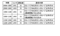
- FIG. 6 is a diagram illustrating a data configuration of a change plan comparison table according to the first embodiment.
- 5 is a flowchart of a network configuration change process according to the first embodiment.
- FIG. 3 is a diagram illustrating a traffic path when changing “storage” traffic to via the Internet according to the first embodiment.
- FIG. 6 is a diagram illustrating a band of data flowing through a link during a lecture viewing according to the first embodiment.
- FIG. 6 is a diagram illustrating a band of data flowing through a link during a lecture viewing according to the first embodiment. It is a figure showing the whole network setting device composition concerning a 2nd embodiment. It is a figure which illustrates the data structure of the mobile terminal database concerning 2nd Embodiment. It is a figure for explaining data stored in a schedule information database concerning a 2nd embodiment. 9 is a flowchart of a network configuration change process according to the second embodiment.
- FIG. 1 is a diagram for explaining a configuration of a network 900 to be set by the network setting device according to the first embodiment.
- the network configuration and data flowing through the network will be described with reference to FIG.
- a base CPE (Customer Premises Equipment) 911 is installed at the base S931, and is connected to the dedicated line 921 by a link L941 and to the Internet 922 by a link L942.
- a terminal T901 exists at the site S931, and is connected to the site CPE 911 via the LAN.
- a base CPE 912 is installed at the base S932, and is connected to the dedicated line 921 by a link L943 and to the Internet 922 by a link L944.
- a terminal T902 exists at the site S932, and is connected to the site CPE 912 via the LAN.
- terminals at the bases S931 and S932 are also collectively referred to as a terminal T910.
- the terminal T910 at the site S931 is connected to the site CPE 911 via the LAN.
- the terminal T910 at the site S932 is connected to the site CPE 912 via the LAN.
- the moving image server 913 is a server that distributes moving images to the terminal T910, and is connected to the dedicated line 921 by a link L951 and to the Internet 922 by a link L953.
- the storage server 914 is a server that provides a storage service to the terminal T910, and is connected to the dedicated line 921 by a link L952 and to the Internet 922 by a link L954.
- the traffic TR01 is traffic (data flow) on the network generated when the user of the terminal T901 views the contents of the moving image server 913, and includes the LAN of the site S931, the site CPE 911, the link L941, the dedicated line 921, Via link L951.
- the traffic TR02 is traffic on the network generated when the user of the terminal T902 views the content of the moving image server 913. Via. If the moving image is a 4K resolution video image, the bandwidth of each of the traffic TR01 and TR02 is 20 Mbps.
- the traffic TR03 is traffic on the network generated when the user of the terminal T910 at the site S931 accesses the storage server 914.
- the traffic TR03 is transmitted through the LAN at the site S931, the site CPE 911, the link L941, the dedicated line 921, and the link L952.
- the traffic TR04 is traffic on the network generated when the user of the terminal T910 at the site S932 accesses the storage server 914, and includes the LAN at the site S932, the site CPE 912, the link L943, the dedicated line 921, and the link L952. Via.
- the average bandwidth of each of the traffic TR03 and TR04 is 25 Mbps.
- the dedicated line 921 is more expensive and of higher quality than the Internet 922, and the IT department has set up a network so that traffic flows through the dedicated line 921 as much as possible. For this reason, the usage rate of the links L941 and L943 is high, and congestion is likely to occur. For this reason, the IT department predicts the use of the network so that congestion does not occur on the links L941 and L943.
- FIG. 2 is a diagram showing the traffic volume for each time zone flowing through the links L941 and L943 according to the first embodiment.
- the change in the communication amount (traffic band) when viewing a moving image will be described with reference to FIG. In the following description of FIG. 2, it is assumed that the users of the terminals T901 and T902 view video images of 4K resolution on the moving image server 913 at 10:00 to 11:00.
- the communication amount flowing through the links L941 and L943 from 9:00 to 10:00 is 35 Mbps.
- the 35 Mbps traffic includes the traffic TR03 and TR04 (see FIG. 1) for the storage server 914, each of which is 25 Mbps.
- the 35 Mbps traffic includes 10 Mbps traffic such as data between the sites S931 and S932 via the site CPE 911, link L941, leased line 921, link L943, and site CPE 912.
- traffics TR01 and TR02 are generated to allow the users of the terminals T901 and T902 to view the video images of 4K resolution on the moving image server 913, and the links L941 and L943 are generated. Respectively increase by 20 Mbps.
- the traffics TR01 and TR02 disappear, and the usage of the links L941 and L943 returns to 35 Mbps from 9:00 to 10:00. If the bandwidth of the links L941 and L943 is smaller than 55 Mbps, congestion will occur at 10:00 to 11:00, causing data loss and communication delay. This may affect not only the users of the terminals T901 and T902 but also the entire users of the bases S931 and S932.
- the IT department switches a part of the traffic flowing through the links L941 and L943 so that the traffic passes through the links L942 and L944 and the Internet 922 instead of the dedicated line 921.
- the usage of the links L941 and L943 can be reduced, and as a result, congestion can be prevented.
- the network setting device acquires information related to the use of the network 900 from among the schedule information registered by the user, and predicts a use situation (traffic). Next, the network setting device generates a network configuration change plan (traffic route change plan or link speed (bandwidth) change plan) according to the usage status and presents it to the IT department network administrator. Subsequently, the network setting device executes the network setting according to the schedule so as to match the proposed network configuration change selected by the network administrator.
- a network configuration change plan (traffic route change plan or link speed (bandwidth) change plan) according to the usage status and presents it to the IT department network administrator.
- bandwidth link speed
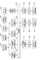
- FIG. 3 is a diagram illustrating an overall configuration of the network setting device 100 according to the first embodiment.
- FIG. 4 is a diagram illustrating a flow of data exchanged between components of the network setting device 100 according to the first embodiment. The overall configuration of the network setting device 100 will be described with reference to FIGS.
- the network setting device 100 includes a control unit 110 including a CPU (Central Processing Unit), a storage unit 120 including a RAM (Random Access Memory) and an SSD (Solid State Drive), and an input / output unit 105. Is done.
- the input / output unit 105 includes a keyboard and a display (not shown) used by a network administrator. Further, the input / output unit 105 includes a communication device (not shown) for exchanging communication data with the network management device 310 and the schedule management server 320 described later via the network 900.
- the network management device 310 is a device for setting and monitoring communication devices such as the base CPEs 911 and 912 and links L941 to L944. By changing the setting, it is possible to change the route of traffic related to a specific application (service). In addition, the network management device 310 acquires statistics (traffic bandwidth information, etc.) of traffic flowing on the link for monitoring.
- the schedule management server 320 stores schedule information of users of the network 900.
- the control unit 110 includes an infrastructure information collection unit 111, a schedule information collection unit 112, a data analysis unit 113, a data evaluation unit 114, and an infrastructure setting unit 115.
- the data analysis unit 113, the data evaluation unit 114, and the infrastructure setting unit 115 are also referred to as a network setting unit.
- the infrastructure information collecting unit 111 obtains the user of the terminal T910, the network configuration, and the network usage status (statistical information) from the network management device 310, and obtains a facility information database described later (in FIG. 3, the facility information DB (Database)). )) (See FIG. 5 described later), the infrastructure configuration database 125, and the infrastructure statistics database 150 (see FIG. 7 described later).
- the infrastructure information collection unit 111 may acquire the equipment information from another apparatus, for example, a directory server or an equipment information management server, without being limited to the network management apparatus 310.
- the schedule information collection unit 112 acquires schedule information related to network use from the schedule management server 320 and stores the schedule information in the schedule information database 160 (see FIG. 8 described below).
- the data analysis unit 113 predicts the use state of the network 900 from the information acquired by the infrastructure information collection unit 111 and the schedule information collection unit 112, and generates a change plan of the network configuration according to the use state.
- the data evaluation unit 114 evaluates each of the network configuration change plans generated by the data analysis unit 113, generates a change plan comparison table 190 (see FIG. 11 described later), and presents it to the network administrator.
- the infrastructure setting unit 115 instructs the network management device 310 to change the network settings to the change plan selected by the network administrator.
- the instruction includes a change time at which the setting change is performed.
- the storage unit 120 includes a facility information database 130, an infrastructure configuration database 125, an infrastructure statistics database 150, a schedule information database 160, a service information database 170, a link cost information database 180, and a change plan comparison table 190. Further, the storage unit 120 stores a program (not shown) for the control unit 110 to execute a network configuration change process (see FIG. 12) described later.
- the infrastructure configuration database 125 is a database that stores the configuration of the network 900 including the link information database 140 (see FIG. 6 described later).
- the facility information database 130, link information database 140, infrastructure statistics database 150, schedule information database 160, service information database 170, link cost information database 180, and change plan comparison table 190 will be described with reference to FIGS. I do.
- FIG. 5 is a diagram illustrating a data configuration of the facility information database 130 according to the first embodiment.
- the equipment information database 130 is, for example, tabular data, and one row (record) indicates the terminal T910 and includes columns (attributes) of the terminal 131, the user 132, and the base 133.
- the terminal 131 is identification information of the terminal indicated by the record.
- the user 132 is identification information of the user of the terminal indicated by the record.
- the site 133 is identification information of the site where the terminal indicated by the record is installed.
- the record 139 indicates that, for a terminal whose identification information is “T901”, the identification information of the user of the terminal is “P4349” and the terminal is installed at the base S931 whose identification information is “S931”.
- FIG. 6 is a diagram illustrating a data configuration of the link information database 140 according to the first embodiment.
- the link information database 140 is, for example, tabular data.
- One row (record) indicates one link, and includes a link 141, a speed 142, and a column (attribute) of the connection point 143.
- the link 141 is identification information of the link indicated by the record.
- the speed 142 is the speed (band) of the link, and the unit is Mbps.
- the connection point 143 indicates a base, a server, or a network to which the link is connected, and includes identification information thereof.
- the record 149 indicates that the link having the identification information “L941” has a speed of 40 Mbps and connects the site S931 and the dedicated line 921.
- FIG. 7 is a diagram illustrating a data configuration of the infrastructure statistics database 150 according to the first embodiment.
- the infrastructure statistics database 150 is, for example, tabular data.
- One row (record) is statistical data of the bandwidth (traffic volume) of traffic flowing through a link, and is classified by link, by period, and by traffic type. Is shown.
- the record includes columns (attributes) of a link 151, a period 152, a type 153, an average 154, a maximum 155, and a daytime 156.
- the link 151 is identification information of the link from which the statistical data has been obtained.
- the period 152 indicates a period during which the statistical data is obtained.
- the type 153 is a type of traffic indicating a communication destination, an application, or a service. For example, “storage” indicating traffic whose storage server 914 (see FIG. 1) is a transmission destination or a transmission source, or a Web server on the Internet 922 There are “Web” indicating access to the Internet, “all” indicating all types of traffic, and the like.
- the average 154, the maximum 155, and the daytime 156 of the traffic band of the type indicated by the type 153 flowing on the link indicated by the link 151 during the period indicated by the period 152 are respectively the average, the maximum, and the daytime average. Is shown.
- the daytime average is an average during business hours.
- the record 159A indicates that the average value of the entire traffic band in the link L941 in June 2018 was 13 Mbps, the maximum value was 40 Mbps, and the average value in the daytime was 35 Mbps.
- the record 159B indicates that the average value of the “storage” traffic on the link L941 in June 2018 was 9 Mbps, the maximum value was 30 Mbps, and the average value in the daytime was 25 Mbps.
- the record 159C indicates that the average value of the bandwidth of the traffic other than “storage” in the link L941 in June 2018 was 4 Mbps, the maximum value was 15 Mbps, and the average value in the daytime was 15 Mbps. Since the time when the maximum value (peak value) is reached differs between “storage” and “other than storage”, the maximum 155 is not the difference between “all” (record 159A) and “storage” (record 159B). In the daytime, it is found that the usage of traffic other than the “storage” flowing through the link L941 is 10 Mbps, and that the “storage” traffic that is an access to the storage server 914 is the main data.
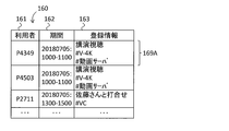
- FIG. 8 is a diagram illustrating a data configuration of the schedule information database 160 according to the first embodiment.
- the schedule information database 160 is, for example, tabular data.
- One row (record) indicates schedule information (plan) of one event registered in the schedule management server 320 (see FIG. 1). 161, a period 162, and a column (attribute) of registration information 163.
- the user 161 is identification information of the user, and the schedule information indicates which user's event.
- the period 162 indicates the period (start time and end time) of the event indicated by the schedule information.
- the registration information 163 is the content of the event indicated by the schedule information.
- the registration information 163 includes a keyword indicating network use. For example, “# V-4K” indicates that a video image of 4K resolution is viewed (event). Further, “# moving image server” indicates the moving image server 913 (see FIG. 1). The other keywords will be described later with reference to FIG.
- the record 169A is a 4K-resolution video image which is scheduled from 10:00 to 11:00 on July 5, 2018 of the user whose identification information is indicated by “P4349” and is stored in the video server 913 (see FIG. 1). Shows an event for viewing.
- FIG. 9 is a diagram illustrating a data configuration of the service information database 170 according to the first embodiment.
- the service information database 170 is, for example, tabular data.
- One row (record) indicates information of one service, and includes a service 171, a used band 172, and a column (attribute) of a keyword 173.
- the service 171 is the name of the service.
- the used band 172 indicates the band of the network (traffic) used by the service.
- the keyword 173 is a common name of the service, and is a keyword excluding “#” included in the registration information 163 of the schedule information (see FIG. 8).
- the record 179 indicates that the bandwidth to be used is 20 Mbps and the service name is “V-4K” for the 4K resolution moving image distribution service.
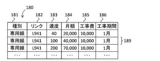
- FIG. 10 is a diagram illustrating a data configuration of the link cost information database 180 according to the first embodiment.
- the link cost information database 180 is, for example, tabular data.
- One row (record) indicates information related to a change in speed (band) for one link, and the type 181, the link 182, the speed 183, Includes columns (attributes) of monthly amount 184, construction cost 185, and construction period 186.
- the type 181 indicates the type of the link, such as “dedicated line” or “Internet”.
- the link 182 indicates identification information of a link whose link speed is to be changed.
- the speed 183 indicates the speed after the speed change.
- the monthly charge 184 indicates a monthly charge after the speed change.
- the construction cost 185 and the construction period 186 indicate the cost and the period of the speed change construction, respectively.
- the record 189 indicates that the cost of the construction for changing the link speed of the link L941 connected to the dedicated line 921 to 100 Mbps is 10,000 yen, the period is January, and the monthly usage fee is 40,000 yen. . Since the current link speed of the link L941 is 40 Mbps (see the record 149 in FIG. 6), it can be seen that the monthly usage fee increases by 20,000 yen.
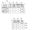
- FIG. 11 is a diagram illustrating a data configuration of a change plan comparison table 190 according to the first embodiment.
- the change plan comparison table 190 is, for example, tabular data.
- One row (record) indicates one network configuration change plan.
- the column (attribute) of the change time 195, the average usage rate 196, the maximum usage rate 197, and the total score 198 is included.
- the change content 191 indicates the content of the network configuration change proposal.
- the construction cost 192 indicates the construction cost required for changing the network configuration.
- the monthly fee increment 193 indicates an increment of the monthly usage fee due to the change.
- the total cost 194 is an increase in the cost in March after the network configuration change, and is calculated using the formula of the construction cost 192 + 3 ⁇ the monthly cost increment 193.
- the change time 195 is the time required for changing the network configuration.
- the average usage rate 196 and the maximum usage rate 197 indicate the higher average usage rate and the maximum usage rate of the expected links L941 and L943 after the network configuration change, respectively, and the unit is a percentage (%).
- the total score 198 is a score of the network configuration change plan, and is calculated using the formula of total cost 194/10000 + change time 195 + average usage rate 196/100 + maximum usage rate 197.
- the change time 195 is converted into minutes, and is set to 40,000 minutes in January.
- a smaller total score 198 is a better change plan because the total cost 194, the average usage rate 196, and the maximum usage rate 197 are lower and the change time 195 is shorter.
- the records 199A to 199C will be described in step S110 in FIG.
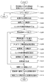
- FIG. 12 is a flowchart of the network configuration change process according to the first embodiment.
- the network configuration change process executed by the network setting device 100 will be described with reference to FIG.
- the network configuration change process is performed at a predetermined timing, for example, periodically.
- step S101 the schedule information collection unit 112 accesses the schedule management server 320, collects schedule information of an event that uses a network that uses a band larger than the predetermined value (has a larger traffic than the predetermined value), and It is stored in the schedule information database 160 (see FIG. 8).
- the event involving the use of a network using a large band is an event in which a keyword included in the keyword 173 of the service information database 170 (see FIG. 9) is described in the schedule information (registration information 163).
- registration information 163 registration information
- step S102 if there is an event involving the use of a network that uses a band larger than the predetermined value in step S101 (step S102 ⁇ Y), the process proceeds to step S103; otherwise (step S102 ⁇ N), the network configuration change process ends.
- step S103 the data analysis unit 113 determines a period for changing the network configuration according to the event.
- the three event periods 162 shown in FIG. 8 are two at 10:00 to 11:00 on July 5, 2018, and one at 13:00 to 15:00. Therefore, the data analysis unit 113 determines that the period is from 10:00 to 11:00 on July 5, 2018, and from 13:00 to 15:00 on the same day.
- step S104 the data analysis unit 113 repeats the processing of steps S105 to S112 for each period determined in step S103.
- a period to be subjected to individual processing to be repeated is referred to as a processing target period.
- the event is repeated twice.
- steps S105 to S112 10:00 to 11:00 on July 5, 2018 will be described as an example.
- step S105 the data analysis unit 113 calculates the expected use bandwidth of the links L941 and L943 in the processing target period.
- the normal usage of the link L941 is 35 Mbps (see the record 159A in FIG. 7).
- the event indicated in the record 169A of FIG. 8 is a 4K resolution lecture viewing on the moving image server 913 by the user whose identification information is “P4349”.
- the terminal used by this user is the terminal T901 at the base S931 (see the record 139 in FIG. 5). Therefore, in the link L941, the bandwidth of 20 Mbps (see the traffic TR01 in FIG. 1 and the record 179 in FIG. 9) increases. Therefore, the expected use bandwidth of the link L941 during the processing target period is expected to be 55 Mbps. Similarly, the expected bandwidth of the link L943 during the processing target period is also expected to be 55 Mbps.
- step S106 the data analysis unit 113 determines whether there is a link whose expected use band exceeds the link bandwidth. If there is a link (step S106 ⁇ Y), the process proceeds to step S107, and if there is no link (step S106 ⁇ N). The process proceeds to step S113. Since the speeds of the links L941 and L943 are 40 Mbps (see FIG. 6), the band is exceeded, so the process proceeds to step S107.
- step S107 the data analysis unit 113 extracts traffic with a large usage amount (data flow of an application (service)) passing through the links L941 and L943.
- a large usage amount data flow of an application (service)
- the traffic whose usage is large on average is 25 Mbps of “storage” (see record 159B in FIG. 7).
- the 25 Mbps of this “storage” and the 20 Mbps of the lecture viewing / listening are the traffic of large usage.
- link L943 the traffic whose usage is large on average is 25 Mbps of “storage” (see record 159B in FIG. 7).
- the 25 Mbps of this “storage” and the 20 Mbps of the lecture viewing / listening are the traffic of large usage.
- step S108 the data analysis unit 113 derives a change plan for the network configuration.
- a change plan there is a plan to increase the speed of a link whose bandwidth is exceeded, and a plan to change a route so that heavy traffic flows through another link.
- Change plan 1 is a plan to change the link speed from 40 Mbps to 100 Mbps (see record 189 in FIG. 10). Since changing the link speed involves construction work, it cannot be changed only during the processing target period, and the changed link is used continuously.
- the second modification is to change the setting of the site CPE 911 so that the “storage” traffic accessing the storage server 914 is routed via the Internet 922 instead of the dedicated line 921 during the processing target period.
- the third modification is to change the setting of the site CPE 911 so that the traffic of the lecture viewing / listening accessing the moving image server 913 is routed via the Internet 922 instead of the dedicated line 921.
- a change plan 4 for changing the link speed similarly, a change plan 5 for changing the “storage” traffic route, and a change plan 6 for changing the lecture viewing traffic route are derived.
- the data analysis unit 113 combines the alternatives 1 and 4, which have the common feature of changing the link speed, and combines the alternatives 2, 5 which have the common feature of changing the “storage” traffic. , And a total of three change plans are derived by combining the change plans 3 and 6, which have the common feature of changing.
- the respective combinations of the change plans 1, 4, the change plans 2, 5, and the change plans 3, 6 are referred to as a change plan 1, a change plan 2, and a change plan 3.
- FIG. 13 is a diagram showing a traffic route when changing “storage” traffic to the Internet 922 according to the first embodiment.
- “storage” traffic TR03 and TR04 flow on the links L942 and L944, respectively.
- FIG. 14 is a diagram showing a band of data flowing through the links L941 and L943 during viewing of a lecture according to the first embodiment.
- a traffic TR01 of viewing / listening at 20 Mbps and traffic of “other than storage” of 10 Mbps flow through link L941.
- FIG. 15 is a diagram showing a route of traffic when the traffic of the lecture viewing / listening is changed via the Internet 922 according to the first embodiment.
- the traffic TR01 and TR02 for viewing the lecture flow on the links L942 and L944, respectively.
- “storage” traffic TR03 and TR04 flow on the links L941 and L943, respectively.
- FIG. 16 is a diagram showing a band of data flowing through the links L941 and L943 during the lecture viewing according to the first embodiment.
- the link L941 is subject to 25 Mbps “storage” traffic TR01 and 10 Mbps “non-storage” traffic. The same applies to link L943.
- step S109 the data analysis unit 113 repeats the process of step S110 for each change plan.
- step S110 the data evaluation unit 114 determines, for each proposed network configuration change, the construction cost 192, the monthly cost increment 193, the total cost 194, the change time 195, the average usage rate 196, the maximum usage rate 197, and the total score 198 (FIG. 11). ).
- the calculation contents of each of the change plans 1 to 3 will be described.
- the record 199A is a record indicating the change plan 1.
- the construction cost 192 is the sum of the construction costs 185 (see FIG. 10) of the links L941 and 943.
- the monthly cost increment 193 is the sum of the increase in the monthly usage fee of each of the links L941 and 943 from 20,000 yen to 40,000 yen, which is 20,000 yen.
- the total cost 194 is a construction cost 192 and a monthly cost increment 193 for three months.
- the change time 195 is one month for both the links L941 and 943.
- the average usage rate 196 is calculated from the fact that the current average is 13 Mbps (see the average 154 of the record 159A in FIG. 7) and the link speed is 100 Mbps.
- the maximum usage rate 197 is the sum of 20 Mbps for lecture viewing, 30 Mbps for “storage” (see a maximum of 155 in record 159B), and 15 Mbps for “other than storage” (see a maximum of 155 in record 159C).
- the total score 198 is calculated using the formula of total cost 194/10000 + change time 195 + average usage rate 196/100 + maximum usage rate 197.
- the record 199B is a record indicating the second modification. If the settings of the bases CPEs 911 and 912 are changed, the change is executed. Therefore, the construction cost 192, the monthly cost increment 193, and the total cost 194 are 0, and the change time 195 is 10 minutes.
- the average usage rate 196 is calculated from the fact that the current average is 13 Mbps and the link speed is 40 Mbps.
- the maximum usage rate 197 is calculated from the sum of 20 Mbps of lecture viewing and listening and 15 Mbps of “other than storage” ((20 + 15) / 40).
- the record 199C is a record indicating the third modification.
- the construction cost 192, the monthly cost increment 193, the total cost 194, the change time 195, and the average usage rate 196 are the same as those of the second modification.
- the maximum usage rate 197 is calculated from the sum of 30 Mbps of “storage” and 15 Mbps of “other than storage” ((30 + 15) / 40).
- step S111 the data analysis unit 113 proceeds to step S112 after executing step S110 for all the proposed changes, and repeats step S110 if there is any remaining.
- step S112 the data evaluation unit 114 stores the construction cost 192, the monthly cost increment 193, the total cost 194, the change time 195, the average usage rate 196, the maximum usage rate 197, and the total score 198 calculated for each change plan in one table. Then, a change plan comparison table 190 is created. For the change plans 1 to 3, the data evaluation unit 114 creates the change plan comparison table 190 including the three records shown in FIG.
- step S113 the data analysis unit 113 proceeds to step S114 after executing steps S105 to S112 for all the processing target periods, and repeats steps S105 to S112 if there is any remaining.
- step S114 the data evaluation unit 114 presents a change plan comparison table 190 for each processing target period to the network administrator. The network administrator selects one configuration plan (change plan) for each processing target period.
- step S115 if the change plan selected by the network administrator is not a plan for link construction but a plan for changing network settings, the infrastructure setting unit 115 determines that the network configuration (traffic route) during the processing target period. Is instructed to change the network management device 310 (see FIG. 1). Specifically, the infrastructure setting unit 115 instructs the network management device 310 to change the traffic route before the processing target period and return the changed traffic route after the processing target period.
- the network setting device 100 acquires from the schedule management server 320 a schedule for network use using a band larger than the predetermined value, and exceeds the band of the links L941 and L943 connecting the dedicated line 921 and the bases S931 and S932. Search for such events.
- the reason for paying attention to the links L941 and L943 is that although the dedicated line 921 has high quality, the speed is lower than the links L942 and L944 to the Internet 922, and congestion is likely to occur.
- the network setting device 100 changes the route of the traffic that uses a large band, generates a change plan via the high-speed Internet 922, and presents the change plan to the network administrator.
- the administrator instructs the network management device 310 to change to the selected plan.
- the change plan includes a plan for changing the speed of the links L941 and L943.
- the change proposal presented to the network administrator includes a construction cost associated with a change in the speed of the link, an increase in the link usage fee, an expected usage rate of the links L941 and L943, and an overall score calculated from these comparison items. Is included. The network administrator selects a change proposal with reference to these comparison items.
- the network administrator would change the network configuration in anticipation of the traffic (bandwidth of traffic).
- the network administrator can change the network configuration (traffic route) according to the planned network usage even if there is no notification from the user, and congestion occurs. Instead, the network can be managed so that the network in the event can be used.
- the network manager does not need to create a change plan, but only has to select from the presented change plans, so that the time for examining the change contents can be reduced.
- the change plan comparison table 190 includes items such as the cost and the usage rate of the link connected to the dedicated line 921, and the network administrator compares these items and selects a change plan. In addition to these items, the change proposal comparison table 190 may include items related to other link usage rates and security.
- the links L942 and L944 connected to the Internet 922 are not included in the change plan comparison table 190 on the premise that the links L942 and L944 have a high speed (broadband) and have a sufficient usage rate.
- the network setting device 100 may include the average usage rate 196 and the maximum usage rate 197 of the links L942 and L944 in the change plan comparison table 190.
- the network setting device 100 sets priorities based on applications (services) and access destinations, such as video viewing, storage, and access to business systems, so that high-priority traffic passes through the dedicated line 921 via the Internet.
- the total score 198 may be calculated so that the score is better than the route passing through 922.
- the traffic route is changed as a change in the network configuration when congestion is predicted.
- the band may be limited.
- the upper limit of the bandwidth of each terminal T910 to the storage server 914 may be determined.
- the traffic may be encrypted (use of an Internet VPN (Virtual Private Network)).
- an IP-VPN Internet Protocol Virtual Private Network
- the data analysis unit 113 generates a network configuration change plan when there is a link where the bandwidth of traffic passing through the link exceeds the speed (band) of the link (see step S106 in FIG. 12). (See step S108).
- the link speed exceeds a predetermined ratio, for example, 90%
- the data analysis unit 113 may generate a change plan.
- the data analysis unit 113 may allow a certain amount of congestion, for example, when it exceeds 105%, generate a change plan.
- the network setting device 100 instructs the network management device 310 on the change plan selected by the network administrator in the change plan comparison table 190.
- the network setting device 100 instructs the network management device 310 to present a change plan having the best total score 198 without presenting the change plan comparison table 190 to the network administrator, and not a plan for link construction. You may.
- the network configuration is changed such that the traffic route is changed so that congestion does not occur for traffic with a large bandwidth predicted from the schedule information.
- the network configuration is changed such that the availability of mobile terminals related to mobile communication and the available position are changed. More specifically, the network setting device acquires registration information related to going out (business trip) from the schedule information registered by the user, and predicts use of the mobile terminal. Next, the network setting device sets the mobile terminal to be used so that it can be used.
- FIG. 17 is a diagram illustrating an overall configuration of a network setting device 100A according to the second embodiment.
- the network setting device 100A includes a control unit 110, a storage unit 120, and an input / output unit 105.
- the input / output unit 105 includes a communication device (not shown) for exchanging communication data with a mobile terminal management server 340 described later via the network 900 in addition to the schedule management server 320.
- the mobile terminal management server 340 manages a mobile terminal 330 described later, and is a server operated by a virtual mobile communication carrier (MVNO (Mobile Virtual Network Operator)) that operates the mobile network 900M.
- MVNO Mobile Virtual Network Operator
- the network setting device 100A can set permission / prohibition of use of the mobile terminal 330 and set an area where the mobile terminal 330 can be used.
- the mobile terminal 330 is prohibited from use by default, and can be used for the first time after the network setting device 100A is set to permit use.
- the mobile terminal 330 is a communication device used when the user goes out, and is connected to the mobile network 900M.
- the personal computer By connecting the personal computer to the mobile terminal 330, the personal computer is connected to the network 900 including the Internet 922 via the mobile network 900M, and can access various business systems and the like at the bases S931 and S932.
- the control unit 110 includes an infrastructure information collection unit 111A, a schedule information collection unit 112A, a data analysis unit 113A, and a mobile terminal setting unit 116.
- the data analysis unit 113A and the mobile terminal setting unit 116 are also referred to as a network setting unit.
- the infrastructure information collection unit 111A acquires a user of the mobile terminal 330 described later from a facility information management server (not shown) and stores the user in the mobile terminal database 210 described later (see FIG. 18 described later).
- the schedule information collection unit 112A acquires schedule information related to going out from the schedule management server 320 and stores the schedule information in the schedule information database 160A (see FIG. 19 described later).
- the data analysis unit 113A predicts the usage status of the mobile terminal 330 from the information acquired by the infrastructure information collection unit 111A and the schedule information collection unit 112A.
- the mobile terminal setting unit 116 instructs the mobile terminal management server 340 to set the mobile terminal 330 so that the mobile terminal 330 corresponding to the predicted usage status can be used.
- the storage unit 120 includes a mobile terminal database 210 (see FIG. 18 described later) and a schedule information database 160A (see FIG. 19 described later).
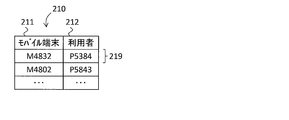
- FIG. 18 is a diagram illustrating a data configuration of the mobile terminal database 210 according to the second embodiment.
- the mobile terminal database 210 is, for example, tabular data.
- One row (record) indicates a mobile terminal, and includes columns (attributes) of the mobile terminal 211 and the user 212.
- the mobile terminal 211 is identification information of the mobile terminal indicated by the record.
- the user 212 is identification information of the user of the mobile terminal indicated by the record.
- the record 219 indicates that the identification information of the user of the mobile terminal whose identification information is “M4832” is “P5384”.
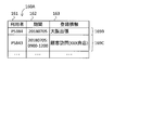
- FIG. 19 is a diagram for explaining data stored in the schedule information database 160A according to the second embodiment.
- the data configuration of the schedule information database 160A is the same as in the first embodiment.
- Record 169B indicates that the user whose identification information is indicated by “P5384” is scheduled for July 5, 2018, and will travel to Osaka.
- the record 169C indicates that the user whose identification information is indicated by “P5843” is scheduled to be on the morning of July 5, 2018, and is going to the customer “XXX shop”.
- FIG. 20 is a flowchart of a network configuration change process according to the second embodiment.
- the network configuration change process executed by the network setting device 100A will be described with reference to FIG.
- the network configuration change process is performed at a predetermined timing, for example, periodically.
- step S131 the schedule information collection unit 112A accesses the schedule management server 320, collects schedule information of an event in which the user goes out, and stores the schedule information in the schedule information database 160A.
- An outing event is an outing due to work including keywords such as “business trip” and “visit”.
- step S132 if there is an event to go out in step S131 (step S132 ⁇ Y), the data analysis unit 113A proceeds to step S133, and if not (step S132 ⁇ N), ends the network configuration change process.
- step S133 the data analysis unit 113A repeats the processing in steps S134 to S136 for each event acquired in step S131. In the following, a period during which individual processing is repeated is referred to as “out of processing target”. In the following description of steps S134 to S136, the event indicated by the records 169B and 169C is taken as an example.
- step S134 the data analysis unit 113A specifies a mobile terminal to be used.
- the data analysis unit 113A can specify the user 161 corresponding to the event in the schedule information database 160A (see FIG. 19), and can specify the mobile terminal by referring to the mobile terminal database 210 (see FIG. 18).
- step S135 the data analysis unit 113A acquires the position of the destination where the processing target is to go. Acquires the address such as the municipalities and the position indicated by the latitude and longitude from the area where the user is going out, customers, buildings, etc.
- step S136 the mobile terminal setting unit 116 sets the use of the mobile terminal. Specifically, the mobile terminal setting unit 116 instructs the mobile terminal management server 340 to use the terminal specified in step S134 at the position acquired in step S135 during the outgoing event period 162 so that the terminal specified in step S134 can use the terminal. Set.
- the mobile terminal 330 whose identification information is “M4832” is set to be usable in Osaka on July 5, 2018.
- the mobile terminal 330 having the identification information “M4802” is set to be available on the morning of July 5, 2018 at the location of “XXX store”.
- step S137 the data analysis unit 113A completes the network configuration change process after executing steps S134 to S136 for all out-of-process targets, and repeats steps S134 to S136 if there is any remaining.
- the mobile terminal cannot be used in the default setting, and can be used by limiting the use period and the use position only when there is a plan to use it on a business trip or the like. By restricting the use in this way, even if the user does not notice that the mobile terminal has been lost or stolen, it is possible to prevent unauthorized use of the mobile terminal.
- the network setting device 100A the network administrator can change the network configuration (use of mobile terminals) according to the planned network usage even if there is no notification from the user.
- the network can be managed so that mobile terminals can be used according to schedule.
- the network setting device 100A instructs the mobile terminal management server 340 operated by the virtual mobile communication carrier to set whether or not the mobile terminal 330 can be used and the use position. May be used.
- the communication from the mobile terminal 330 may be identified at the connection point (gateway) between the organization's network and the external network, and the communication may be restricted.
- the present invention includes components such as infrastructure information collecting units 111 and 111A, schedule information collecting units 112 and 112A, data analyzing units 113 and 113A, data evaluating unit 114, infrastructure setting unit 115, mobile terminal setting unit 116, and flowcharts. Can be changed as appropriate without departing from the spirit of the present invention.
- Network setting device 111 100, 100A Network setting device 111, 111A Infrastructure information collecting unit 112, 112A Schedule information collecting unit 113, 113A Data analysis unit (network setting unit) 114 Data evaluation unit (network setting unit) 115 Infrastructure setting unit (Network setting unit) 116 Mobile terminal setting unit (network setting unit) 125 infrastructure configuration database 130 equipment information database 140 link information database 150 infrastructure statistics database 160 schedule information database 170 service information database 180 link cost information database 190 change proposal comparison table 210 mobile terminal database 310 network management device 320 schedule management server 340 mobile terminal management Server 913 Video server 914 Storage server 921 Dedicated line 922 Internet
Landscapes
- Engineering & Computer Science (AREA)
- Signal Processing (AREA)
- Computer Networks & Wireless Communication (AREA)
- General Physics & Mathematics (AREA)
- Physics & Mathematics (AREA)
- Algebra (AREA)
- Mathematical Analysis (AREA)
- Mathematical Optimization (AREA)
- Mathematical Physics (AREA)
- Probability & Statistics with Applications (AREA)
- Pure & Applied Mathematics (AREA)
- Environmental & Geological Engineering (AREA)
- Data Exchanges In Wide-Area Networks (AREA)
Abstract
【課題】予測されるネットワークの利用状況に応じた適切なネットワーク構成に設定することを可能とする。 【解決手段】スケジュール情報収集部112は、ネットワークの利用者のスケジュール情報から、ネットワークを利用するイベントの予定を取得する。データ分析部113は、イベントの予定から、ネットワークの利用状況を予測し、イベントにあるネットワーク利用が可能となるような前記ネットワークの構成の変更案を生成する。インフラ設定部115は、変更案のネットワーク構成となるように、ネットワーク管理装置310にネットワーク設定を指示する。
Description
本発明は、ネットワークの利用状況に応じた適切なネットワーク構成に設定するネットワーク設定装置およびネットワーク設定方法に関する。
企業を始めとする組織のIT部門は、拠点内、拠点間、およびインターネットと組織間のネットワークの利用状況を監視したり、利用者からのネットワーク利用予定の通知を受けたりして、ネットワークの利用状況を予測し、ネットワークトラフィック(以下、トラフィックとも記す)の経路設定を行う。こうすることで、IT部門は、ネットワーク管理の1つとして、ネットワークの品質を維持している。
例えば、サーバと端末とを接続する複数の通信経路があり、最短経路のトラフィックの帯域がその経路上にあるリンクの速度(帯域)を上回る場合には、IT部門は、一部のアプリケーションのトラフィックを別の経路を流れるように設定することで、輻輳が発生することを回避する。IT部門が決定したスケジュールに基づいて、経路を設定するネットワーク設定を実施する手法として特許文献1に記載のソフトウェアを用いる手法がある。
輻輳を引き起こすようなトラフィックとして、講演の動画視聴やビデオ会議などがある。利用者は、自身の都合のよいときに録画済みの動画を視聴したり、参加者の都合に合わせてビデオ会議の日時を設定したりする。動画視聴やビデオ会議の予定は、利用者個人のスケジュールとしてスケジューラ(スケジュール管理サーバ)に登録されている。
非特許文献2には、スケジュールを参照して事前に予定を通知する装置が記載されている。利用者は、このような装置から通知を受けて、予定した日時に動画視聴したり、ビデオ会議に参加したりする。しかしながら、IT部門は、個々の利用者のスケジュールまでは管理していない。
非特許文献2には、スケジュールを参照して事前に予定を通知する装置が記載されている。利用者は、このような装置から通知を受けて、予定した日時に動画視聴したり、ビデオ会議に参加したりする。しかしながら、IT部門は、個々の利用者のスケジュールまでは管理していない。
IT部門が行う、ネットワーク品質維持以外のネットワーク管理として、セキュリティ管理がある。セキュリティ管理の1つとして、ネットワーク利用者が外出時に利用するモバイル端末のセキュリティ管理があり、紛失や盗難などにより所在不明となったモバイル端末の利用を停止する運用が行われている。
1.2.3 スケジュール制御、JP1/Automatic Job Management System 2 解説、[online]、2006年6月、日立製作所、[平成30年8月28日検索]、インターネット<URL: http://itdoc.hitachi.co.jp/manuals/3020/30203K2143/AJSF0016.HTM>
cloudiss、[online]、2015年11月、Cerevo、[平成30年8月28日検索]、インターネット<URL:https://cloudiss.cerevo.com/ja/>
IT部門は、動画視聴のような広帯域の(大きな帯域を使用する)トラフィックが発生するネットワーク利用について、利用者からの事前の通知があれば、輻輳が発生しないように、ネットワークの設定(ネットワーク構成の変更)を行うことができる。しかしながら、利用者個人の予定としてスケジューラに登録されているだけで、事前の通知がない場合には、IT部門は対応できない。この結果、広帯域のトラフィックにより、輻輳が発生してしまい、利用者本人のネットワーク利用にとどまらず、他の利用者のネットワーク利用についても、遅延やデータの欠落が生じてしまうという問題が発生する。
また、モバイル端末の紛失や盗難については、ネットワーク利用者からの通知を受けてからIT部門が、モバイル端末の利用停止の設定を行っている。ネットワーク利用者が、紛失や盗難に気がつかない、または、気がついても通知を怠れば、モバイル端末の利用可能な状態が継続し、組織のネットワークへの不正アクセスや犯罪に利用される可能性が出てくる。
本発明は、このような背景を鑑みてなされたものであって、予定されているネットワーク利用情報を収集してネットワークの利用状況を予測し、ネットワークの利用状況に応じた適切なネットワーク構成に設定することを可能とするネットワーク設定装置およびネットワーク設定方法を提供することを課題とする。
前記した課題を解決するため、請求項1に記載の発明は、ネットワークの構成を変更するネットワーク設定装置であって、前記ネットワークの利用者のスケジュール情報から、前記ネットワークを利用するイベントの予定を取得するスケジュール情報収集部と、前記イベントの予定から、前記ネットワークの利用状況を予測し、前記利用が可能となるように前記ネットワークの構成を変更するネットワーク設定部とを備えることを特徴とするネットワーク設定装置とした。
また、請求項7に記載の発明は、ネットワークの構成を変更するネットワーク設定装置のネットワーク設定方法であって、前記ネットワーク設定装置が、前記ネットワークの利用者のスケジュール情報から、前記ネットワークを利用するイベントの予定を取得するステップと、前記イベントの予定から、前記ネットワークの利用状況を予測し、前記利用が可能となるように前記ネットワークの構成を変更するステップとを実行することを特徴とするネットワーク設定方法とした。
このような構成にすることで、ネットワーク設定装置は、スケジュール情報に記載されたネットワーク利用に対応するようにネットワーク構成を変更する。このため、スケジュール情報に係る利用者は、イベントに対応したネットワーク利用が可能になる。
請求項2に記載の発明は、前記ネットワーク設定部が、前記イベントの実施期間における前記ネットワークに流れるトラフィックの経路と帯域を算出して、前記トラフィックの経路と帯域から前記ネットワークを構成するリンクの使用帯域を算出し、前記使用帯域が所定の値を超える場合には、前記リンクを流れるトラフィックのなかにある一部のトラフィックの経路を変更するように前記ネットワークの構成を変更することを特徴とする請求項1に記載のネットワーク設定装置とした。
このような構成にすることで、ネットワーク設定装置は、イベントに伴い新たなトラフィックが発生しても、輻輳が発生することがないように、ネットワーク構成を変更する。大きな帯域を使用するネットワーク利用を伴うイベントであっても、利用者は、通信遅延が小さい一定品質のネットワーク利用が可能となる。
請求項3に記載の発明は、前記ネットワーク設定部が、前記ネットワークの構成を変更する変更案を複数生成して出力し、選択された前記変更案のネットワークの構成に変更することを特徴とする請求項2に記載のネットワーク設定装置とした。
このような構成にすることで、ネットワーク管理者は、ネットワーク設定装置が出力した複数のネットワーク構成変更案のなかで、最良の変更案を採用することができる。また、ネットワーク管理者は、事前にネットワーク構成の変更内容を知ることができる。
請求項4に記載の発明は、前記ネットワーク設定部が、前記イベントが、前記ネットワークを構成し、前記利用者が利用するモバイル端末を利用するイベントである場合に、前記イベントの実施期間中における前記モバイル端末が利用可能であるように前記ネットワークの構成を変更することを特徴とする請求項1に記載のネットワーク設定装置とした。
このような構成にすることで、ネットワーク設定装置は、モバイル端末の利用を制限できるようになる。利用者からの通知がなくても、紛失や盗難などにより所在不明となったモバイル端末の利用制限が可能となり、モバイル端末の不正利用を抑止することができる。
請求項5に記載の発明は、ネットワークの構成を変更するネットワーク設定装置であって、前記ネットワークの利用者のスケジュール情報から、前記ネットワークを利用するイベントの予定を取得するスケジュール情報収集部と、前記イベントの実施期間における前記ネットワークに流れるトラフィックの経路と帯域を算出して、前記トラフィックの経路と帯域から前記ネットワークを構成するリンクの使用帯域を算出し、前記使用帯域が所定の値を超える場合には、前記リンクを流れるトラフィックのなかにある一部のトラフィックの経路を変更する前記ネットワークの構成の変更案と、前記使用帯域が所定の値を超えるリンクの速度を変更する前記ネットワークの構成の変更案とを生成して出力し、前記トラフィックの経路を変更する前記ネットワークの構成の変更案の選択を受け付けた場合には、当該トラフィックの経路を変更するように前記ネットワークの構成を変更するネットワーク設定部とを備えることを特徴とするネットワーク設定装置とした。
このような構成にすることで、ネットワーク設定装置は、イベントに伴い新たなトラフィックが発生しても、輻輳が発生することがないように、リンクの速度を変更するネットワーク構成の変更案と、トラフィックの経路を変更するネットワーク構成の変更案とをネットワーク管理者に提示する。ネットワーク管理者がトラフィックの経路を変更する変更案を選択した場合には、ネットワーク設定装置は、ネットワーク構成の変更を行う。ネットワーク管理者は、リンクの速度の変更を含む複数のネットワーク構成変更案のなかで、最良の変更案を採用することができる。また、ネットワーク管理者は、事前にネットワーク構成の変更内容を知ることができる。
請求項6に記載の発明は、前記ネットワーク設定部が、前記ネットワークの構成の変更後における前記リンクの使用帯域率を算出して変更案を生成して出力することを特徴とする請求項5に記載のネットワーク設定装置とした。
このような構成にすることで、ネットワーク管理者は、ネットワーク設定装置が出力した変更後のリンクの使用帯域率を参照しながら変更案を比較して選択できるようになり、より適切な選択ができるようになる。
本発明によれば、予定されているネットワーク利用情報を収集してネットワークの利用状況を予測し、ネットワークの利用状況に応じた適切なネットワーク構成に設定することを可能とするネットワーク設定装置およびネットワーク設定方法を提供することができる。
≪第1の実施形態:予測される輻輳(リンクの帯域を超過するトラフィック)への対応≫
本発明を実施するための第1の実施形態であるネットワーク設定装置を説明する前に、第1の実施形態におけるネットワーク構成、輻輳が発生する状況、および輻輳を回避するためのネットワーク設定の概要を説明する。
本発明を実施するための第1の実施形態であるネットワーク設定装置を説明する前に、第1の実施形態におけるネットワーク構成、輻輳が発生する状況、および輻輳を回避するためのネットワーク設定の概要を説明する。
≪第1の実施形態:ネットワーク構成≫
図1は、第1の実施形態に係るネットワーク設定装置の設定対象となるネットワーク900の構成を説明するための図である。図1を参照しながら、ネットワーク構成とネットワークを流れるデータについて説明する。
拠点S931には、拠点CPE(Customer Premises Equipment)911が設置されており、専用線921とはリンクL941で、インターネット922とはリンクL942で接続されている。拠点S931には端末T901が存在し、LAN経由で拠点CPE911と接続されている。
図1は、第1の実施形態に係るネットワーク設定装置の設定対象となるネットワーク900の構成を説明するための図である。図1を参照しながら、ネットワーク構成とネットワークを流れるデータについて説明する。
拠点S931には、拠点CPE(Customer Premises Equipment)911が設置されており、専用線921とはリンクL941で、インターネット922とはリンクL942で接続されている。拠点S931には端末T901が存在し、LAN経由で拠点CPE911と接続されている。
拠点S932には、拠点CPE912が設置されており、専用線921とはリンクL943で、インターネット922とはリンクL944で接続されている。拠点S932には端末T902が存在し、LAN経由で拠点CPE912と接続されている。
なお、以下では、拠点S931,S932にある端末を総称して端末T910とも記す。拠点S931にある端末T910はLAN経由で拠点CPE911に接続されている。拠点S932にある端末T910はLAN経由で拠点CPE912に接続されている。
動画サーバ913は、端末T910に向けて動画を配信するサーバであり、専用線921とはリンクL951で、インターネット922とはリンクL953で接続されている。ストレージサーバ914は、端末T910に対してストレージサービスを提供するサーバであり、専用線921とはリンクL952で、インターネット922とはリンクL954で接続されている。
≪第1の実施形態:ネットワークを流れるデータ≫
トラフィックTR01は、端末T901の利用者が、動画サーバ913のコンテンツを視聴するときに発生するネットワーク上のトラフィック(データの流れ)であり、拠点S931のLAN、拠点CPE911、リンクL941、専用線921およびリンクL951を経由している。また、トラフィックTR02は、端末T902の利用者が、動画サーバ913のコンテンツを視聴するときに発生するネットワーク上のトラフィックであり、拠点S932のLAN、拠点CPE912、リンクL943、専用線921およびリンクL951を経由している。動画が4K解像度のビデオ画像であれば、トラフィックTR01,TR02それぞれの帯域は20Mbpsである。
トラフィックTR01は、端末T901の利用者が、動画サーバ913のコンテンツを視聴するときに発生するネットワーク上のトラフィック(データの流れ)であり、拠点S931のLAN、拠点CPE911、リンクL941、専用線921およびリンクL951を経由している。また、トラフィックTR02は、端末T902の利用者が、動画サーバ913のコンテンツを視聴するときに発生するネットワーク上のトラフィックであり、拠点S932のLAN、拠点CPE912、リンクL943、専用線921およびリンクL951を経由している。動画が4K解像度のビデオ画像であれば、トラフィックTR01,TR02それぞれの帯域は20Mbpsである。
トラフィックTR03は、拠点S931の端末T910の利用者が、ストレージサーバ914にアクセスするときに発生するネットワーク上のトラフィックであって、拠点S931のLAN、拠点CPE911、リンクL941、専用線921およびリンクL952を経由している。また、トラフィックTR04は、拠点S932の端末T910の利用者が、ストレージサーバ914にアクセスするときに発生するネットワーク上のトラフィックであり、拠点S932のLAN、拠点CPE912、リンクL943、専用線921およびリンクL952を経由している。トラフィックTR03,TR04の平均的な帯域は、それぞれ25Mbpsである。
インターネット922と比べて専用線921は、高価で高品質であり、IT部門は、可能な限りトラフィックが専用線921を流れるように、ネットワークを設定している。このために、リンクL941,L943の使用率は高く、輻輳が発生しやすい。このため、IT部門は、ネットワーク利用を予測して、リンクL941,L943で輻輳が発生しないようにしている。
図2は、第1の実施形態に係り、リンクL941,L943を流れる時間帯別の通信量を示す図である。図2を参照しながら、動画視聴時の通信量(トラフィックの帯域)の変化を説明する。なお、以下の図2の説明においては、10時~11時に、端末T901,T902それぞれの利用者が、動画サーバ913上にある4K解像度のビデオ画像を視聴するとする。
9時~10時にリンクL941,L943を流れる通信量は、35Mbpsである。この35Mbpsのトラフィックには、ストレージサーバ914向けのトラフィックTR03,TR04(図1参照)が含まれ、それぞれ25Mbpsである。また、この35Mbpsのトラフィックには、拠点CPE911、リンクL941、専用線921、リンクL943、拠点CPE912を経由する拠点S931,S932間のデータなど10Mbpsのトラフィックが含まれている。
10時~11時には、端末T901,T902それぞれの利用者が、動画サーバ913上にある4K解像度のビデオ画像を視聴するために、トラフィックTR01,TR02(図1参照)が発生し、リンクL941,L943の通信量がそれぞれ20Mbps増加する。
11時~12時には、トラフィックTR01,TR02がなくなり、リンクL941,L943の使用量は、9時~10時の35Mbpsに戻る。
リンクL941,L943の帯域が55Mbpsより小さければ、10時~11時に輻輳が発生してしまい、データ欠落や通信遅延が発生してしまう。端末T901,T902の利用者だけではなく、拠点S931,S932の利用者全体に影響を及ぼす可能性がある。
リンクL941,L943の帯域が55Mbpsより小さければ、10時~11時に輻輳が発生してしまい、データ欠落や通信遅延が発生してしまう。端末T901,T902の利用者だけではなく、拠点S931,S932の利用者全体に影響を及ぼす可能性がある。
10時~11時のビデオ視聴が予め分かっていれば、IT部門は、リンクL941,L943を流れるトラフィックの一部を、専用線921ではなく、リンクL942,L944およびインターネット922を経由するように切り替えることで、リンクL941,L943の使用量を下げることができ、結果として輻輳を防止することができるようになる。
≪第1の実施形態:ネットワーク設定装置の概要≫
本発明の実施形態であるネットワーク設定装置は、利用者が登録したスケジュール情報のなかでネットワーク900の利用に係る情報を取得して、利用状況(トラフィック)を予測する。次に、ネットワーク設定装置は、利用状況に応じたネットワーク構成の変更案(トラフィックの経路の変更案やリンク速度(帯域)の変更案)を生成して、IT部門のネットワーク管理者に提示する。続いて、ネットワーク設定装置は、スケジュールに合わせて、ネットワーク管理者が選択したネットワーク構成の変更案に合致するように、ネットワーク設定を実行する。以下では、ネットワーク設定装置の構成、および、スケジュール情報の取得からネットワーク構成の変更案の生成、ネットワーク設定までの処理を説明する。
本発明の実施形態であるネットワーク設定装置は、利用者が登録したスケジュール情報のなかでネットワーク900の利用に係る情報を取得して、利用状況(トラフィック)を予測する。次に、ネットワーク設定装置は、利用状況に応じたネットワーク構成の変更案(トラフィックの経路の変更案やリンク速度(帯域)の変更案)を生成して、IT部門のネットワーク管理者に提示する。続いて、ネットワーク設定装置は、スケジュールに合わせて、ネットワーク管理者が選択したネットワーク構成の変更案に合致するように、ネットワーク設定を実行する。以下では、ネットワーク設定装置の構成、および、スケジュール情報の取得からネットワーク構成の変更案の生成、ネットワーク設定までの処理を説明する。
≪第1の実施形態:ネットワーク設定装置の全体構成≫
図3は、第1の実施形態に係るネットワーク設定装置100の全体構成を示す図である。図4は、第1の実施形態に係るネットワーク設定装置100の構成要素間でやり取りされるデータの流れを示す図である。図3および図4を参照しながら、ネットワーク設定装置100の全体構成を説明する。
図3は、第1の実施形態に係るネットワーク設定装置100の全体構成を示す図である。図4は、第1の実施形態に係るネットワーク設定装置100の構成要素間でやり取りされるデータの流れを示す図である。図3および図4を参照しながら、ネットワーク設定装置100の全体構成を説明する。
ネットワーク設定装置100は、CPU(Central Processing Unit)から構成される制御部110、RAM(Random Access Memory)やSSD(Solid State Drive)などから構成される記憶部120および入出力部105を含んで構成される。入出力部105は、ネットワーク管理者が利用するキーボードやディスプレイ(不図示)を備える。また、入出力部105は、後記するネットワーク管理装置310およびスケジュール管理サーバ320との通信データを、ネットワーク900を介してやり取りする通信デバイス(不図示)を備える。
ネットワーク管理装置310は、拠点CPE911,912などの通信装置やリンクL941~L944などの設定や監視を行う装置である。設定の変更を行うことで、特定のアプリケーション(サービス)に係るトラフィックの経路を変更するができる。また、ネットワーク管理装置310は、監視のためにリンクを流れるトラフィックの統計(トラフィックの帯域情報など)を取得している。
スケジュール管理サーバ320は、ネットワーク900の利用者のスケジュール情報を蓄積している。
スケジュール管理サーバ320は、ネットワーク900の利用者のスケジュール情報を蓄積している。
≪第1の実施形態:ネットワーク設定装置の全体構成:制御部の構成≫
制御部110は、インフラ情報収集部111、スケジュール情報収集部112、データ分析部113、データ評価部114およびインフラ設定部115を備える。なお、データ分析部113とデータ評価部114とインフラ設定部115とを合わせてネットワーク設定部とも記す。
制御部110は、インフラ情報収集部111、スケジュール情報収集部112、データ分析部113、データ評価部114およびインフラ設定部115を備える。なお、データ分析部113とデータ評価部114とインフラ設定部115とを合わせてネットワーク設定部とも記す。
インフラ情報収集部111は、ネットワーク管理装置310から、端末T910の利用者やネットワーク構成、ネットワークの利用状況(統計情報)を取得して、後記する設備情報データベース(図3では、設備情報DB(Database)と記載)130(後記する図5参照)、インフラ構成データベース125およびインフラ統計データベース150(後記する図7参照)に格納する。なお、インフラ情報収集部111は、ネットワーク管理装置310に限らず別の装置、例えば、ディレクトリサーバや設備情報管理サーバなどから設備情報を取得してもよい。
スケジュール情報収集部112は、スケジュール管理サーバ320からネットワーク利用に係るスケジュール情報を取得して、後記するスケジュール情報データベース160(後記する図8参照)に格納する。
データ分析部113は、インフラ情報収集部111やスケジュール情報収集部112が取得した情報から、ネットワーク900の利用状況を予測し、利用状況に応じたネットワーク構成の変更案を生成する。
データ分析部113は、インフラ情報収集部111やスケジュール情報収集部112が取得した情報から、ネットワーク900の利用状況を予測し、利用状況に応じたネットワーク構成の変更案を生成する。
データ評価部114は、データ分析部113が生成したネットワーク構成の変更案それぞれについて評価を行い、変更案比較表190(後記する図11参照)を生成して、ネットワーク管理者に提示する。
インフラ設定部115は、ネットワーク管理者が選択した変更案にネットワーク設定を変更するように、ネットワーク管理装置310に指示する。指示には、設定変更を実行する変更時刻も含まれる。
インフラ設定部115は、ネットワーク管理者が選択した変更案にネットワーク設定を変更するように、ネットワーク管理装置310に指示する。指示には、設定変更を実行する変更時刻も含まれる。
≪第1の実施形態:ネットワーク設定装置の全体構成:記憶部の構成≫
記憶部120は、設備情報データベース130、インフラ構成データベース125、インフラ統計データベース150、スケジュール情報データベース160、サービス情報データベース170、リンクコスト情報データベース180および変更案比較表190を含んで構成される。また、記憶部120は、後記するネットワーク構成変更処理(図12参照)を制御部110が実行するためのプログラム(不図示)を記憶する。
記憶部120は、設備情報データベース130、インフラ構成データベース125、インフラ統計データベース150、スケジュール情報データベース160、サービス情報データベース170、リンクコスト情報データベース180および変更案比較表190を含んで構成される。また、記憶部120は、後記するネットワーク構成変更処理(図12参照)を制御部110が実行するためのプログラム(不図示)を記憶する。
インフラ構成データベース125は、リンク情報データベース140(後記する図6参照)を含めたネットワーク900の構成を記憶しているデータベースである。以下、図5~図11を参照しながら、設備情報データベース130、リンク情報データベース140、インフラ統計データベース150、スケジュール情報データベース160、サービス情報データベース170、リンクコスト情報データベース180および変更案比較表190を説明する。
≪第1の実施形態:ネットワーク設定装置の全体構成:設備情報データベースの構成≫
図5は、第1の実施形態に係る設備情報データベース130のデータ構成を例示する図である。設備情報データベース130は、例えば表形式のデータであって、1つの行(レコード)は、端末T910を示し、端末131、利用者132および拠点133の列(属性)を含む。
図5は、第1の実施形態に係る設備情報データベース130のデータ構成を例示する図である。設備情報データベース130は、例えば表形式のデータであって、1つの行(レコード)は、端末T910を示し、端末131、利用者132および拠点133の列(属性)を含む。
端末131は、レコードが示している端末の識別情報である。利用者132は、レコードが示す端末の利用者の識別情報である。拠点133はレコードが示す端末が設置されている拠点の識別情報である。
レコード139は、識別情報が「T901」である端末について、端末の利用者の識別情報は「P4349」であり、識別情報が「S931」である拠点S931に設置されていることを示す。
レコード139は、識別情報が「T901」である端末について、端末の利用者の識別情報は「P4349」であり、識別情報が「S931」である拠点S931に設置されていることを示す。
≪第1の実施形態:ネットワーク設定装置の全体構成:リンク情報データベースの構成≫
図6は、第1の実施形態に係るリンク情報データベース140のデータ構成を例示する図である。リンク情報データベース140は、例えば表形式のデータであって、1つの行(レコード)は、1本のリンクを示し、リンク141、速度142および接続点143の列(属性)を含む。
図6は、第1の実施形態に係るリンク情報データベース140のデータ構成を例示する図である。リンク情報データベース140は、例えば表形式のデータであって、1つの行(レコード)は、1本のリンクを示し、リンク141、速度142および接続点143の列(属性)を含む。
リンク141は、レコードが示すリンクの識別情報である。速度142は、リンクの速度(帯域)であって、単位はMbpsである。接続点143は、リンクの接続する拠点やサーバ、ネットワークを示し、その識別情報が含まれている。
レコード149は、識別情報が「L941」であるリンクについて、速度は40Mbpsであって、拠点S931と専用線921とを接続していることを示す。
レコード149は、識別情報が「L941」であるリンクについて、速度は40Mbpsであって、拠点S931と専用線921とを接続していることを示す。
≪第1の実施形態:ネットワーク設定装置の全体構成:インフラ統計データベースの構成≫
図7は、第1の実施形態に係るインフラ統計データベース150のデータ構成を例示する図である。インフラ統計データベース150は、例えば表形式のデータであって、1つの行(レコード)は、リンクに流れるトラフィックの帯域(通信量)の統計データであって、リンク別、期間別、トラフィックの種別別の帯域を示す。レコードは、リンク151、期間152、種別153、平均154、最大155および昼間156の列(属性)を含む。
図7は、第1の実施形態に係るインフラ統計データベース150のデータ構成を例示する図である。インフラ統計データベース150は、例えば表形式のデータであって、1つの行(レコード)は、リンクに流れるトラフィックの帯域(通信量)の統計データであって、リンク別、期間別、トラフィックの種別別の帯域を示す。レコードは、リンク151、期間152、種別153、平均154、最大155および昼間156の列(属性)を含む。
リンク151は、統計データが取得されたリンクの識別情報である。期間152は、統計データが取得された期間を示す。
種別153は、通信先やアプリケーション、サービスを示すトラフィックの種別であって、例えば、ストレージサーバ914(図1参照)が送信先または送信元であるトラフィックを示す「ストレージ」やインターネット922上のWebサーバへのアクセスを示す「Web」、全ての種別のトラフィックを示す「全体」などがある。
種別153は、通信先やアプリケーション、サービスを示すトラフィックの種別であって、例えば、ストレージサーバ914(図1参照)が送信先または送信元であるトラフィックを示す「ストレージ」やインターネット922上のWebサーバへのアクセスを示す「Web」、全ての種別のトラフィックを示す「全体」などがある。
期間152に示される期間にリンク151に示されるリンク上を流れた種別153に示される種別のトラフィックの帯域について、平均154、最大155および昼間156は、それぞれ平均値、最大値および昼間の平均値を示す。なお、昼間の平均値とは、業務時間における平均値である。
レコード159Aは、リンクL941における2018年6月における全体のトラフィックの帯域について、平均値は13Mbps、最大値は40Mbps、昼間の平均値は35Mbpsであったことを示している。次に、レコード159Bは、リンクL941における2018年6月の「ストレージ」のトラフィックについて、平均値は9Mbps、最大値は30Mbps、昼間の平均値は25Mbpsであったことを示している。
また、レコード159Cは、リンクL941における2018年6月の「ストレージ以外」のトラフィックの帯域について、平均値は4Mbps、最大値は15Mbps、昼間の平均値は15Mbpsであったことを示している。最大値(ピーク値)になる時間が、「ストレージ」と「ストレージ以外」で異なるため、最大155は、「全体」(レコード159A)と「ストレージ」(レコード159B)との差になっていない。昼間においては、リンクL941を流れる「ストレージ」以外のトラフィックの使用量は10Mbpsであることが判り、ストレージサーバ914へのアクセスである「ストレージ」のトラフィックが主要なデータであることが判る。
≪第1の実施形態:ネットワーク設定装置の全体構成:スケジュール情報データベースの構成≫
図8は、第1の実施形態に係るスケジュール情報データベース160のデータ構成を例示する図である。スケジュール情報データベース160は、例えば表形式のデータであって、1つの行(レコード)は、スケジュール管理サーバ320(図1参照)に登録されている1つのイベントのスケジュール情報(予定)を示し、利用者161、期間162および登録情報163の列(属性)を含む。
図8は、第1の実施形態に係るスケジュール情報データベース160のデータ構成を例示する図である。スケジュール情報データベース160は、例えば表形式のデータであって、1つの行(レコード)は、スケジュール管理サーバ320(図1参照)に登録されている1つのイベントのスケジュール情報(予定)を示し、利用者161、期間162および登録情報163の列(属性)を含む。
利用者161は、利用者の識別情報であって、スケジュール情報がどの利用者のイベントかを示す。期間162は、スケジュール情報が示すイベントの期間(開始時刻と終了時刻)を示す。登録情報163は、スケジュール情報が示すイベントの内容である。
登録情報163は、ネットワーク利用を示すキーワードを含む。例えば、「#V-4K」は、4K解像度のビデオ画像を視聴すること(イベント)を示している。また、「#動画サーバ」は、動画サーバ913(図1参照)を示している。他のキーワードについては、後記する図9で説明する。
レコード169Aは、識別情報が「P4349」で示される利用者の2018年7月5日の10時から11時までの予定であって、動画サーバ913(図1参照)にある4K解像度のビデオ画像を視聴するイベントを示している。
レコード169Aは、識別情報が「P4349」で示される利用者の2018年7月5日の10時から11時までの予定であって、動画サーバ913(図1参照)にある4K解像度のビデオ画像を視聴するイベントを示している。
≪第1の実施形態:ネットワーク設定装置の全体構成:サービス情報データベースの構成≫
図9は、第1の実施形態に係るサービス情報データベース170のデータ構成を例示する図である。サービス情報データベース170は、例えば表形式のデータであって、1つの行(レコード)は、1つのサービスの情報を示し、サービス171、使用帯域172およびキーワード173の列(属性)を含む。
図9は、第1の実施形態に係るサービス情報データベース170のデータ構成を例示する図である。サービス情報データベース170は、例えば表形式のデータであって、1つの行(レコード)は、1つのサービスの情報を示し、サービス171、使用帯域172およびキーワード173の列(属性)を含む。
サービス171は、サービスの名称である。使用帯域172は、サービスが使用するネットワーク(トラフィック)の帯域を示す。キーワード173は、サービスの通称であり、スケジュール情報の登録情報163(図8参照)に含まれる「#」を除くキーワードである。
レコード179は、4K解像度の動画配信のサービスについて、使用する帯域は20Mbpsであって、通称は「V-4K」であることを示している。
レコード179は、4K解像度の動画配信のサービスについて、使用する帯域は20Mbpsであって、通称は「V-4K」であることを示している。
≪第1の実施形態:ネットワーク設定装置の全体構成:リンクコスト情報データベースの構成≫
図10は、第1の実施形態に係るリンクコスト情報データベース180のデータ構成を例示する図である。リンクコスト情報データベース180は、例えば表形式のデータであって、1つの行(レコード)は、1本のリンクについて、速度(帯域)変更に係る情報を示し、種別181、リンク182、速度183、月額184、工事費185および工事期間186の列(属性)を含む。
図10は、第1の実施形態に係るリンクコスト情報データベース180のデータ構成を例示する図である。リンクコスト情報データベース180は、例えば表形式のデータであって、1つの行(レコード)は、1本のリンクについて、速度(帯域)変更に係る情報を示し、種別181、リンク182、速度183、月額184、工事費185および工事期間186の列(属性)を含む。
種別181は、リンクの種別を示し、「専用線」、「インターネット」などがある。リンク182は、リンク速度を変更するリンクの識別情報を示す。速度183は、速度変更後の速度を示す。月額184は、速度変更後の月額使用料金を示す。工事費185および工事期間186は、速度変更工事の費用および期間をそれぞれ示す。
レコード189は、専用線921に接続するリンクL941のリンク速度を100Mbpsに変更する工事について費用は1万円、期間は1月であって、月額使用料金は4万円であることを示している。現在のリンクL941のリンク速度は40Mbps(図6のレコード149参照)であるので、月額使用料金は2万円の増額になることが判る。
≪第1の実施形態:ネットワーク設定装置の全体構成:変更案比較表の構成≫
図11は、第1の実施形態に係る変更案比較表190のデータ構成を例示する図である。変更案比較表190は、例えば表形式のデータであって、1つの行(レコード)は、1つのネットワーク構成変更案を示し、変更内容191、工事費192、月額費増分193、合計費用194、変更時間195、平均使用率196、最大使用率197および総合スコア198の列(属性)を含む。
図11は、第1の実施形態に係る変更案比較表190のデータ構成を例示する図である。変更案比較表190は、例えば表形式のデータであって、1つの行(レコード)は、1つのネットワーク構成変更案を示し、変更内容191、工事費192、月額費増分193、合計費用194、変更時間195、平均使用率196、最大使用率197および総合スコア198の列(属性)を含む。
変更内容191は、ネットワーク構成変更案の内容を示す。工事費192は、ネットワーク構成変更にかかる工事費用を示す。月額費増分193は、変更による月額使用料金の増分を示す。
合計費用194は、ネットワーク構成変更後の3月における費用の増分であって、工事費192+3×月額費増分193の式を用いて算出される。変更時間195は、ネットワーク構成変更に要する時間である。
合計費用194は、ネットワーク構成変更後の3月における費用の増分であって、工事費192+3×月額費増分193の式を用いて算出される。変更時間195は、ネットワーク構成変更に要する時間である。
平均使用率196および最大使用率197は、ネットワーク構成変更後の予想されるリンクL941,L943の高い方の平均使用率および最大使用率をそれぞれ示し、単位は百分率(%)である。
総合スコア198は、ネットワーク構成変更案のスコアであり、合計費用194/10000+変更時間195+平均使用率196/100+最大使用率197の式を用いて算出される。変更時間195は分換算であって、1月は4万分とする。総合スコア198が小さい方が、合計費用194や平均使用率196、最大使用率197が低く、変更時間195が短いため、より良い変更案となる。
レコード199A~199Cについては、図12のステップS110で説明する。
総合スコア198は、ネットワーク構成変更案のスコアであり、合計費用194/10000+変更時間195+平均使用率196/100+最大使用率197の式を用いて算出される。変更時間195は分換算であって、1月は4万分とする。総合スコア198が小さい方が、合計費用194や平均使用率196、最大使用率197が低く、変更時間195が短いため、より良い変更案となる。
レコード199A~199Cについては、図12のステップS110で説明する。
≪第1の実施形態:ネットワーク構成変更処理≫
図12は、第1の実施形態に係るネットワーク構成変更処理のフローチャートである。図12を参照しながら、ネットワーク設定装置100が実行するネットワーク構成変更処理を説明する。ネットワーク構成変更には、リンク速度の変更およびトラフィックの経路変更の2種類がある。ネットワーク構成変更処理は、所定のタイミング、例えば定期的に実行される。
図12は、第1の実施形態に係るネットワーク構成変更処理のフローチャートである。図12を参照しながら、ネットワーク設定装置100が実行するネットワーク構成変更処理を説明する。ネットワーク構成変更には、リンク速度の変更およびトラフィックの経路変更の2種類がある。ネットワーク構成変更処理は、所定のタイミング、例えば定期的に実行される。
ステップS101において、スケジュール情報収集部112は、スケジュール管理サーバ320にアクセスして、所定値より大きな帯域を使用する(所定値より通信量の多い)ネットワーク利用を伴うイベントのスケジュール情報を収集して、スケジュール情報データベース160(図8参照)に格納する。大きな帯域を使用するネットワーク利用を伴うイベントとは、サービス情報データベース170(図9参照)のキーワード173に含まれるキーワードが、スケジュール情報(登録情報163)に記載されたイベントである。以下では、図8に示される3つのイベントのスケジュール情報が収集されたとして、説明を続ける。
ステップS102において、ステップS101で所定値より大きな帯域を使用するネットワーク利用を伴うイベントがあれば(ステップS102→Y)ステップS103に進み、なければ(ステップS102→N)ネットワーク構成変更処理を終了する。
ステップS103において、データ分析部113は、イベントに応じて、ネットワーク構成を変更する期間を決定する。図8に示される3つのイベントの期間162は、2018年7月5日の10時~11時が2件と13時~15時の1件である。このため、データ分析部113は、期間を2018年7月5日の10時~11時と、同日の13時~15時と決定する。
ステップS103において、データ分析部113は、イベントに応じて、ネットワーク構成を変更する期間を決定する。図8に示される3つのイベントの期間162は、2018年7月5日の10時~11時が2件と13時~15時の1件である。このため、データ分析部113は、期間を2018年7月5日の10時~11時と、同日の13時~15時と決定する。
ステップS104において、データ分析部113は、ステップS103で決定した期間ごとに、ステップS105~S112の処理を繰り返す。以下では、繰り返す個々の処理の対象となる期間を処理対象期間と記す。図8に記載された3つのイベントの例では、2回繰り返すことになる。以下のステップS105~S112の説明では、2018年7月5日の10時~11時を例として説明する。
ステップS105において、データ分析部113は、リンクL941,L943の処理対象期間における予想使用帯域を算出する。リンクL941の通常の使用量は、35Mbpsである(図7のレコード159A参照)。
図8のレコード169Aに示されるイベントは、識別情報が「P4349」である利用者による動画サーバ913にある4K解像度の講演視聴である。この利用者が利用する端末は、拠点S931にある端末T901である(図5のレコード139参照)。このため、リンクL941においては、20Mbpsの帯域(図1のトラフィックTR01および図9のレコード179参照)が増加することになる。このため、処理対象期間におけるリンクL941の予想使用帯域は55Mbpsと予想される。同様にして、処理対象期間におけるリンクL943の予想使用帯域も55Mbpsと予想される。
図12に戻り、説明を続ける。ステップS106において、データ分析部113は、予想使用帯域がリンクの帯域を超過するリンクがあるか判断して、リンクがあれば(ステップS106→Y)ステップS107に進み、なければ(ステップS106→N)ステップS113に進む。リンクL941,L943の速度は40Mbps(図6参照)であるため、帯域超過となるのでステップS107に進む。
ステップS107において、データ分析部113は、リンクL941,L943を通過する使用量の大きいトラフィック(アプリケーション(サービス)のデータの流れ)を抽出する。リンクL941については、平均的に使用量の大きいトラフィックは「ストレージ」の25Mbpsであると予想される(図7のレコード159B参照)。この「ストレージ」の25Mbpsと、講演視聴の20Mbpsとが使用量の大きいトラフィックとなる。リンクL943についても同様である。
ステップS108において、データ分析部113は、ネットワーク構成の変更案を導出する。変更案には、帯域が超過するリンクの速度を上げる案、使用量の大きいトラフィックが別のリンクを流れるように経路を変更する案がある。
リンクL941については、3つの案が導出される。変更案1は、リンク速度を40Mbpsから100Mbps(図10のレコード189参照)に変更する案である。リンク速度を変更には、工事が伴うため、処理対象期間の間だけ変更することはできず、変更したリンクを使い続けることになる。
変更案2は、処理対象期間の間、ストレージサーバ914にアクセスする「ストレージ」のトラフィックを、専用線921ではなくインターネット922経由になるように、拠点CPE911の設定を変更する案である。
変更案2は、処理対象期間の間、ストレージサーバ914にアクセスする「ストレージ」のトラフィックを、専用線921ではなくインターネット922経由になるように、拠点CPE911の設定を変更する案である。
変更案3は、動画サーバ913にアクセスする講演視聴のトラフィックを、専用線921ではなくインターネット922経由になるように、拠点CPE911の設定を変更する案である。
リンクL943についても、同様にして、リンク速度を変更する変更案4、「ストレージ」のトラフィックの経路を変更する変更案5、および講演視聴のトラフィックの経路を変更する変更案6が導出される。
リンクL943についても、同様にして、リンク速度を変更する変更案4、「ストレージ」のトラフィックの経路を変更する変更案5、および講演視聴のトラフィックの経路を変更する変更案6が導出される。
リンクL941,L943の両方の帯域超過を解決するために、変更案1~3それぞれについて、変更案4~6を組み合わせる9通りの変更案が導出される。データ分析部113は、リンク速度変更という共通点がある変更案1,4を組み合わせ、「ストレージ」のトラフィックを変更するという共通点がある変更案2,5を組みわせ、さらに、講演視聴のトラフィックを変更するという共通点がある変更案3,6を組み合わせて、合計3つの変更案を導出する。以下では、変更案1,4、変更案2,5および変更案3,6のそれぞれの組み合わせを変更案1、変更案2および変更案3と記す。
図13は、第1の実施形態に係る、「ストレージ」のトラフィックをインターネット922経由に変更する場合のトラフィックの経路を示す図である。講演視聴のトラフィックTR01,TR02は、それぞれリンクL941,L943上を流れる。一方、「ストレージ」のトラフィックTR03,TR04は、それぞれリンクL942,L944上を流れる。
図14は、第1の実施形態に係る、講演視聴中にリンクL941,L943を流れるデータの帯域を示す図である。講演視聴中にリンクL941には、20Mbpsの講演視聴のトラフィックTR01と、10Mbpsの「ストレージ以外」のトラフィック(図7のレコード159Cの昼間156参照)が流れる。リンクL943についても同様である。
図15は、第1の実施形態に係る、講演視聴のトラフィックをインターネット922経由に変更する場合のトラフィックの経路を示す図である。講演視聴のトラフィックTR01,TR02は、それぞれリンクL942,L944上を流れる。一方、「ストレージ」のトラフィックTR03,TR04は、それぞれリンクL941,L943上を流れる。
図16は、第1の実施形態に係る、講演視聴中にリンクL941,L943を流れるデータの帯域を示す図である。講演視聴中にリンクL941には、25Mbpsの「ストレージ」のトラフィックTR01と、10Mbpsの「ストレージ以外」のトラフィックが流れる。リンクL943についても同様である。
図12に戻り、説明を続ける。ステップS109において、データ分析部113は、ステップS110の処理を変更案ごとに繰り返す。
ステップS110において、データ評価部114は、ネットワーク構成変更案ごとに、工事費192、月額費増分193、合計費用194、変更時間195、平均使用率196、最大使用率197および総合スコア198(図11参照)を算出する。以下、変更案1~3のそれぞれの算出内容を説明する。
ステップS110において、データ評価部114は、ネットワーク構成変更案ごとに、工事費192、月額費増分193、合計費用194、変更時間195、平均使用率196、最大使用率197および総合スコア198(図11参照)を算出する。以下、変更案1~3のそれぞれの算出内容を説明する。
レコード199Aは、変更案1を示すレコードである。工事費192は、リンクL941,943の工事費185(図10参照)の和である。月額費増分193は、リンクL941,943のそれぞれの月額利用料金が2万円から4万円への増額分2万円の合計である。合計費用194は、工事費192と3カ月分の月額費増分193である。変更時間195は、リンクL941,943ともに1月である。平均使用率196は、現在の平均が13Mbps(図7のレコード159Aの平均154参照)であり、リンク速度が100Mbpsであることから算出する。最大使用率197は、講演視聴の20Mbpsと、「ストレージ」の30Mbps(レコード159Bの最大155参照)と、「ストレージ以外」の15Mbps(レコード159Cの最大155参照)の和である。総合スコア198は、合計費用194/10000+変更時間195+平均使用率196/100+最大使用率197の式を用いて算出される。
レコード199Bは、変更案2を示すレコードである。拠点CPE911,912の設定を変更すれば変更が実行されるので、工事費192、月額費増分193、合計費用194は0であって、変更時間195は10分である。平均使用率196は、現在の平均が13Mbpsであり、リンク速度が40Mbpsであることから算出する。最大使用率197は、講演視聴の20Mbpsと、「ストレージ以外」の15Mbpsの和から算出される((20+15)/40)。
レコード199Cは、変更案3を示すレコードである。工事費192、月額費増分193、合計費用194、変更時間195および平均使用率196は、変更案2と同様である。最大使用率197は、「ストレージ」の30Mbpsと、「ストレージ以外」の15Mbpsの和から算出される((30+15)/40)。
ステップS111において、データ分析部113は、全ての変更案についてステップS110を実行したらステップS112に進み、残りがあれば、ステップS110を繰り返す。
ステップS112において、データ評価部114は、変更案ごとに算出した工事費192、月額費増分193、合計費用194、変更時間195、平均使用率196、最大使用率197および総合スコア198を1つの表にまとめて変更案比較表190を作成する。変更案1~3では、データ評価部114は、図11に示した3つのレコードからなる変更案比較表190を作成する。
ステップS112において、データ評価部114は、変更案ごとに算出した工事費192、月額費増分193、合計費用194、変更時間195、平均使用率196、最大使用率197および総合スコア198を1つの表にまとめて変更案比較表190を作成する。変更案1~3では、データ評価部114は、図11に示した3つのレコードからなる変更案比較表190を作成する。
ステップS113において、データ分析部113は、全ての処理対象期間についてステップS105~S112を実行したらステップS114に進み、残りがあれば、ステップS105~S112を繰り返す。
ステップS114において、データ評価部114は、ネットワーク管理者に、処理対象期間ごとの変更案比較表190を提示する。ネットワーク管理者は、処理対象期間ごとに1つの構成案(変更案)を選択する。
ステップS114において、データ評価部114は、ネットワーク管理者に、処理対象期間ごとの変更案比較表190を提示する。ネットワーク管理者は、処理対象期間ごとに1つの構成案(変更案)を選択する。
ステップS115において、インフラ設定部115は、ネットワーク管理者が選択した変更案がリンク工事をする案ではなく、ネットワーク設定を変更する案であれば、処理対象期間中に、ネットワーク構成(トラフィックの経路)を変更するように、ネットワーク管理装置310(図1参照)に指示する。詳しくは、インフラ設定部115は、処理対象期間前にトラフィックの経路を変更して、処理対象期間後に変更したトラフィックの経路を戻すように、ネットワーク管理装置310に指示する。
≪第1の実施形態:ネットワーク構成変更処理の特徴≫
ネットワーク設定装置100は、スケジュール管理サーバ320から、所定値より大きな帯域を使用するネットワーク利用の予定を取得して、専用線921と拠点S931,S932とを接続するリンクL941,L943の帯域を超過するようなイベントを探索する。リンクL941,L943に着目する理由は、専用線921は、高品質ではあるが、インターネット922へのリンクL942,L944と比べて速度が遅く、輻輳が発生しやすいからである。このようなイベントの予定があれば、ネットワーク設定装置100は、大きな帯域を使用するトラフィックの経路を変更して、高速なインターネット922を経由する変更案を生成してネットワーク管理者に提示し、ネットワーク管理者が選択した案に変更するようにネットワーク管理装置310に指示する。変更案には、リンクL941,L943の速度を変更する案も含まれる。
ネットワーク設定装置100は、スケジュール管理サーバ320から、所定値より大きな帯域を使用するネットワーク利用の予定を取得して、専用線921と拠点S931,S932とを接続するリンクL941,L943の帯域を超過するようなイベントを探索する。リンクL941,L943に着目する理由は、専用線921は、高品質ではあるが、インターネット922へのリンクL942,L944と比べて速度が遅く、輻輳が発生しやすいからである。このようなイベントの予定があれば、ネットワーク設定装置100は、大きな帯域を使用するトラフィックの経路を変更して、高速なインターネット922を経由する変更案を生成してネットワーク管理者に提示し、ネットワーク管理者が選択した案に変更するようにネットワーク管理装置310に指示する。変更案には、リンクL941,L943の速度を変更する案も含まれる。
ネットワーク管理者に提示される変更案には、リンクの速度変更に伴う工事費用、リンク利用料金の増加金額、予想されるリンクL941,L943の使用率、および、これらの比較項目から算出した総合スコアが含まれる。ネットワーク管理者は、これらの比較項目を参照して、変更案を選択する。
従来までは、利用者からのネットワーク利用の予定の通知があれば、ネットワーク管理者は通信量(トラフィックの帯域)を予想して、ネットワーク構成を変更していた。ネットワーク設定装置100を用いることで、利用者からの通知がなくても、ネットワーク管理者は、予定されているネットワーク利用に応じたネットワーク構成(トラフィックの経路)に変更することができ、輻輳が発生せず、イベントにあるネットワーク利用が可能となるようにネットワークを管理できる。また、ネットワーク管理者は、変更案を作成する必要はなく、提示された変更案から選択すればよいので、変更内容を検討する時間を短縮することができる。
≪第1の実施形態:変形例:変更案比較表≫
変更案比較表190は、専用線921に接続されるリンクの費用や使用率などの項目を含み、ネットワーク管理者は、これらの項目を比較して変更案を選択している。これらの項目の他に、変更案比較表190は、他のリンクの使用率やセキュリティに係る項目を含んでもよい。
変更案比較表190は、専用線921に接続されるリンクの費用や使用率などの項目を含み、ネットワーク管理者は、これらの項目を比較して変更案を選択している。これらの項目の他に、変更案比較表190は、他のリンクの使用率やセキュリティに係る項目を含んでもよい。
第1の実施形態では、インターネット922に接続されるリンクL942,L944は、高速(広帯域)で使用率に余裕があるという前提で、変更案比較表190には含まれていなかった。ネットワーク設定装置100は、変更案比較表190にリンクL942,L944の平均使用率196や最大使用率197を含めるようにしてもよい。
また、ネットワーク設定装置100は、動画視聴、ストレージ、業務システムのアクセスなど、アプリケーション(サービス)やアクセス先などに基づいて優先度を設け、優先度の高いトラフィックが専用線921を通る経路が、インターネット922を通る経路よりスコアが良くなるように、総合スコア198を算出してもよい。
≪第1の実施形態:変形例:ネットワーク構成変更内容≫
第1の実施形態では、輻輳が予測される場合のネットワーク構成の変更として、トラフィックの経路を変更している。経路変更の他に、帯域の制限を行うようにしてもよい。例えば、ストレージサーバ914のアクセスについて、個々の端末T910のストレージサーバ914への帯域の上限を定めるようにしてもよい。
また、専用線921からインターネット922にトラフィックの経路を変更する場合に、トラフィックを暗号化(インターネットVPN(Virtual Private Network)の利用)してもよい。また、専用線921の他にIP-VPN(Internet Protocol Virtual Private Network)を用いてもよい。
第1の実施形態では、輻輳が予測される場合のネットワーク構成の変更として、トラフィックの経路を変更している。経路変更の他に、帯域の制限を行うようにしてもよい。例えば、ストレージサーバ914のアクセスについて、個々の端末T910のストレージサーバ914への帯域の上限を定めるようにしてもよい。
また、専用線921からインターネット922にトラフィックの経路を変更する場合に、トラフィックを暗号化(インターネットVPN(Virtual Private Network)の利用)してもよい。また、専用線921の他にIP-VPN(Internet Protocol Virtual Private Network)を用いてもよい。
≪第1の実施形態:変形例:トラフィックとリンクとの帯域比較≫
第1の実施形態では、データ分析部113は、リンクを通るトラフィックの帯域がリンクの速度(帯域)を超過するリンクがある(図12のステップS106参照)ときに、ネットワーク構成の変更案を生成している(ステップS108参照)。リンク速度の所定の割合、例えば90%、を超えるときに、データ分析部113は、変更案を生成するようにしてもよい。または、ある程度の輻輳までは許容して、例えば105%を超えるときには、データ分析部113は、変更案を生成するようにしてもよい。
第1の実施形態では、データ分析部113は、リンクを通るトラフィックの帯域がリンクの速度(帯域)を超過するリンクがある(図12のステップS106参照)ときに、ネットワーク構成の変更案を生成している(ステップS108参照)。リンク速度の所定の割合、例えば90%、を超えるときに、データ分析部113は、変更案を生成するようにしてもよい。または、ある程度の輻輳までは許容して、例えば105%を超えるときには、データ分析部113は、変更案を生成するようにしてもよい。
≪第1の実施形態:変形例:ネットワーク管理者に提示することなく最良案の変更実施≫
第1の実施形態は、ネットワーク設定装置100は、変更案比較表190のなかでネットワーク管理者が選択した変更案をネットワーク管理装置310に指示している。これに対して、ネットワーク設定装置100は、ネットワーク管理者に変更案比較表190を提示することなく、リンク工事をする案ではない、総合スコア198が最良の変更案をネットワーク管理装置310に指示してもよい。
第1の実施形態は、ネットワーク設定装置100は、変更案比較表190のなかでネットワーク管理者が選択した変更案をネットワーク管理装置310に指示している。これに対して、ネットワーク設定装置100は、ネットワーク管理者に変更案比較表190を提示することなく、リンク工事をする案ではない、総合スコア198が最良の変更案をネットワーク管理装置310に指示してもよい。
≪第2の実施形態:予測されるモバイル通信への対応≫
第1の実施形態では、スケジュール情報から予測される帯域が大きいトラフィックについて、輻輳が発生しないようにトラフィックの経路を変更するというネットワーク構成の変更を行っている。第2の実施形態では、スケジュール情報から予測されるモバイル通信について、モバイル通信に係るモバイル端末の利用可否や利用可能位置を変更するというネットワーク構成の変更を行う。詳しくは、ネットワーク設定装置は、利用者が登録したスケジュール情報のなかで外出(出張)に係る登録情報を取得して、モバイル端末の利用を予測する。次に、ネットワーク設定装置は、利用されるモバイル端末が使用できるように設定する。
第1の実施形態では、スケジュール情報から予測される帯域が大きいトラフィックについて、輻輳が発生しないようにトラフィックの経路を変更するというネットワーク構成の変更を行っている。第2の実施形態では、スケジュール情報から予測されるモバイル通信について、モバイル通信に係るモバイル端末の利用可否や利用可能位置を変更するというネットワーク構成の変更を行う。詳しくは、ネットワーク設定装置は、利用者が登録したスケジュール情報のなかで外出(出張)に係る登録情報を取得して、モバイル端末の利用を予測する。次に、ネットワーク設定装置は、利用されるモバイル端末が使用できるように設定する。
≪第2の実施形態:ネットワーク設定装置の全体構成≫
図17は、第2の実施形態に係るネットワーク設定装置100Aの全体構成を示す図である。ネットワーク設定装置100Aは、制御部110、記憶部120および入出力部105を含んで構成される。入出力部105は、スケジュール管理サーバ320の他に後記するモバイル端末管理サーバ340との通信データを、ネットワーク900を介してやり取りする通信デバイス(不図示)を備える。
図17は、第2の実施形態に係るネットワーク設定装置100Aの全体構成を示す図である。ネットワーク設定装置100Aは、制御部110、記憶部120および入出力部105を含んで構成される。入出力部105は、スケジュール管理サーバ320の他に後記するモバイル端末管理サーバ340との通信データを、ネットワーク900を介してやり取りする通信デバイス(不図示)を備える。
モバイル端末管理サーバ340は、後記するモバイル端末330を管理するサーバであって、モバイルネットワーク900Mを運営する仮想移動体通信事業者(MVNO(Mobile Virtual Network Operator))が運用するサーバである。モバイル端末管理サーバ340に指示を出すことにより、ネットワーク設定装置100Aは、モバイル端末330の使用の許可/禁止を設定したり、使用できる地域を設定したりすることができる。モバイル端末330は、既定では使用禁止であって、ネットワーク設定装置100Aにから使用を許可する設定がされて、始めて使用できる。
モバイル端末330は、利用者が外出時に利用する通信装置であって、モバイルネットワーク900Mに接続される。パソコンをモバイル端末330に接続することで、モバイルネットワーク900Mを介して、パソコンがインターネット922を含むネットワーク900に接続され、拠点S931,S932にある各種業務システム他にアクセス可能となる。
≪第2の実施形態:ネットワーク設定装置の全体構成:制御部の構成≫
制御部110は、インフラ情報収集部111A、スケジュール情報収集部112A、データ分析部113Aおよびモバイル端末設定部116を備える。なお、データ分析部113Aとモバイル端末設定部116とを合わせてネットワーク設定部とも記す。
インフラ情報収集部111Aは、設備情報管理サーバ(不図示)から、後記するモバイル端末330の利用者を取得して、後記するモバイル端末データベース210(後記する図18参照)に格納する。
制御部110は、インフラ情報収集部111A、スケジュール情報収集部112A、データ分析部113Aおよびモバイル端末設定部116を備える。なお、データ分析部113Aとモバイル端末設定部116とを合わせてネットワーク設定部とも記す。
インフラ情報収集部111Aは、設備情報管理サーバ(不図示)から、後記するモバイル端末330の利用者を取得して、後記するモバイル端末データベース210(後記する図18参照)に格納する。
スケジュール情報収集部112Aは、スケジュール管理サーバ320から外出に係るスケジュール情報を取得して、スケジュール情報データベース160A(後記する図19参照)に格納する。
データ分析部113Aは、インフラ情報収集部111Aやスケジュール情報収集部112Aが取得した情報から、モバイル端末330の利用状況を予測する。
モバイル端末設定部116は、モバイル端末管理サーバ340に指示して、予測された利用状況に対応したモバイル端末330の利用が可能となるように、モバイル端末330の設定を行う。
データ分析部113Aは、インフラ情報収集部111Aやスケジュール情報収集部112Aが取得した情報から、モバイル端末330の利用状況を予測する。
モバイル端末設定部116は、モバイル端末管理サーバ340に指示して、予測された利用状況に対応したモバイル端末330の利用が可能となるように、モバイル端末330の設定を行う。
≪第2の実施形態:ネットワーク設定装置の全体構成:記憶部の構成≫
記憶部120は、モバイル端末データベース210(後記する図18参照)およびスケジュール情報データベース160A(後記する図19参照)を含んで構成される。
図18は、第2の実施形態に係るモバイル端末データベース210のデータ構成を例示する図である。モバイル端末データベース210は、例えば表形式のデータであって、1つの行(レコード)は、モバイル端末を示し、モバイル端末211および利用者212の列(属性)を含む。
記憶部120は、モバイル端末データベース210(後記する図18参照)およびスケジュール情報データベース160A(後記する図19参照)を含んで構成される。
図18は、第2の実施形態に係るモバイル端末データベース210のデータ構成を例示する図である。モバイル端末データベース210は、例えば表形式のデータであって、1つの行(レコード)は、モバイル端末を示し、モバイル端末211および利用者212の列(属性)を含む。
モバイル端末211は、レコードが示すモバイル端末の識別情報である。利用者212は、レコードが示すモバイル端末の利用者の識別情報である。
レコード219は、識別情報が「M4832」であるモバイル端末の利用者の識別情報は「P5384」であることを示す。
レコード219は、識別情報が「M4832」であるモバイル端末の利用者の識別情報は「P5384」であることを示す。
図19は、第2の実施形態に係るスケジュール情報データベース160Aに格納されるデータを説明するための図である。スケジュール情報データベース160Aのデータ構成は、第1の実施形態と同様である。レコード169Bは、識別情報が「P5384」で示される利用者の2018年7月5日の予定であって、大阪に出張することを示している。レコード169Cは、識別情報が「P5843」で示される利用者の2018年7月5日午前の予定であって、顧客である「XXX商店」に出張することを示している。
≪第2の実施形態:ネットワーク構成変更処理≫
図20は、第2の実施形態に係るネットワーク構成変更処理のフローチャートである。図20を参照しながら、ネットワーク設定装置100Aが実行するネットワーク構成変更処理を説明する。ネットワーク構成変更処理は、所定のタイミング、例えば定期的に実行される。
図20は、第2の実施形態に係るネットワーク構成変更処理のフローチャートである。図20を参照しながら、ネットワーク設定装置100Aが実行するネットワーク構成変更処理を説明する。ネットワーク構成変更処理は、所定のタイミング、例えば定期的に実行される。
ステップS131において、スケジュール情報収集部112Aは、スケジュール管理サーバ320にアクセスして、利用者が外出するイベントのスケジュール情報を収集して、スケジュール情報データベース160Aに格納する。外出するイベントとは、「出張」や「訪問」などのキーワードを含む業務による外出である。
ステップS132において、データ分析部113Aは、ステップS131で外出するイベントがあれば(ステップS132→Y)ステップS133に進み、なければ(ステップS132→N)ネットワーク構成変更処理を終了する。
ステップS133において、データ分析部113Aは、ステップS131で取得したイベントごとに、ステップS134~S136の処理を繰り返す。以下では、繰り返す個々の処理の対象となる期間を処理対象外出と記す。以下のステップS134~S136の説明では、レコード169B,169Cで示されるイベントを例とする。
ステップS133において、データ分析部113Aは、ステップS131で取得したイベントごとに、ステップS134~S136の処理を繰り返す。以下では、繰り返す個々の処理の対象となる期間を処理対象外出と記す。以下のステップS134~S136の説明では、レコード169B,169Cで示されるイベントを例とする。
ステップS134において、データ分析部113Aは、利用されるモバイル端末を特定する。データ分析部113Aは、スケジュール情報データベース160A(図19参照)においてイベントに対応する利用者161を特定し、モバイル端末データベース210(図18参照)を参照すれば、モバイル端末を特定できる。
ステップS135において、データ分析部113Aは、処理対象外出の外出先の位置を取得する。外出先の地域や顧客、ビルなどから、市区町村などの住所や緯度経度で示される位置を取得する。
ステップS136において、モバイル端末設定部116は、モバイル端末の利用を設定する。詳しくは、モバイル端末設定部116は、外出するイベントの期間162に、ステップS134で特定した端末が、ステップS135で取得した位置で利用できるように、モバイル端末管理サーバ340に指示して、利用を設定する。
ステップS136において、モバイル端末設定部116は、モバイル端末の利用を設定する。詳しくは、モバイル端末設定部116は、外出するイベントの期間162に、ステップS134で特定した端末が、ステップS135で取得した位置で利用できるように、モバイル端末管理サーバ340に指示して、利用を設定する。
例えば、図19のレコード169Bに示される処理対象外出の場合には、識別情報が「M4832」であるモバイル端末330について、2018年7月5日に大阪で利用できるように設定する。レコード169Cに示される処理対象外出の場合には、識別情報が「M4802」であるモバイル端末330について、2018年7月5日午前に「XXX商店」の所在地で利用できるように設定する。
ステップS137において、データ分析部113Aは、全ての処理対象外出についてステップS134~S136を実行したらネットワーク構成変更処理を終え、残りがあれば、ステップS134~S136を繰り返す。
≪第2の実施形態:ネットワーク構成変更処理の特徴≫
モバイル端末は、既定の設定では利用不可となっており、出張などで利用の予定がある場合にのみ、利用期間や利用位置を限定して利用可能となる。このように利用を限定することで、モバイル端末の紛失や盗難に利用者が気付かなかったとしても、不正なモバイル端末の利用を防止することができる。
ネットワーク設定装置100Aを用いることで、利用者からの通知がなくても、ネットワーク管理者は、予定されているネットワーク利用に応じたネットワーク構成(モバイル端末の利用可否)に変更することができ、利用予定に応じてモバイル端末が利用可能となるようにネットワークを管理できる。
モバイル端末は、既定の設定では利用不可となっており、出張などで利用の予定がある場合にのみ、利用期間や利用位置を限定して利用可能となる。このように利用を限定することで、モバイル端末の紛失や盗難に利用者が気付かなかったとしても、不正なモバイル端末の利用を防止することができる。
ネットワーク設定装置100Aを用いることで、利用者からの通知がなくても、ネットワーク管理者は、予定されているネットワーク利用に応じたネットワーク構成(モバイル端末の利用可否)に変更することができ、利用予定に応じてモバイル端末が利用可能となるようにネットワークを管理できる。
≪第2の実施形態:変形例≫
第2の実施形態では、ネットワーク設定装置100Aは、仮想移動体通信事業者が運用するモバイル端末管理サーバ340に指示して、モバイル端末330の利用可否や利用位置の設定をしているが、他の手段を用いてもよい。例えば、組織のネットワークと外部のネットワークとの接続点(ゲートウェイ)で、モバイル端末330からの通信を識別して、通信を制限するようにしてもよい。
第2の実施形態では、ネットワーク設定装置100Aは、仮想移動体通信事業者が運用するモバイル端末管理サーバ340に指示して、モバイル端末330の利用可否や利用位置の設定をしているが、他の手段を用いてもよい。例えば、組織のネットワークと外部のネットワークとの接続点(ゲートウェイ)で、モバイル端末330からの通信を識別して、通信を制限するようにしてもよい。
≪その他変形例≫
なお、本発明は、インフラ情報収集部111,111A、スケジュール情報収集部112,112A、データ分析部113,113A、データ評価部114、インフラ設定部115、モバイル端末設定部116などの構成要素、フローチャートに記載された処理内容は、本発明の趣旨を逸脱しない範囲で適宜変更が可能である。
なお、本発明は、インフラ情報収集部111,111A、スケジュール情報収集部112,112A、データ分析部113,113A、データ評価部114、インフラ設定部115、モバイル端末設定部116などの構成要素、フローチャートに記載された処理内容は、本発明の趣旨を逸脱しない範囲で適宜変更が可能である。
100,100A ネットワーク設定装置
111,111A インフラ情報収集部
112,112A スケジュール情報収集部
113,113A データ分析部(ネットワーク設定部)
114 データ評価部(ネットワーク設定部)
115 インフラ設定部(ネットワーク設定部)
116 モバイル端末設定部(ネットワーク設定部)
125 インフラ構成データベース
130 設備情報データベース
140 リンク情報データベース
150 インフラ統計データベース
160 スケジュール情報データベース
170 サービス情報データベース
180 リンクコスト情報データベース
190 変更案比較表
210 モバイル端末データベース
310 ネットワーク管理装置
320 スケジュール管理サーバ
340 モバイル端末管理サーバ
913 動画サーバ
914 ストレージサーバ
921 専用線
922 インターネット
111,111A インフラ情報収集部
112,112A スケジュール情報収集部
113,113A データ分析部(ネットワーク設定部)
114 データ評価部(ネットワーク設定部)
115 インフラ設定部(ネットワーク設定部)
116 モバイル端末設定部(ネットワーク設定部)
125 インフラ構成データベース
130 設備情報データベース
140 リンク情報データベース
150 インフラ統計データベース
160 スケジュール情報データベース
170 サービス情報データベース
180 リンクコスト情報データベース
190 変更案比較表
210 モバイル端末データベース
310 ネットワーク管理装置
320 スケジュール管理サーバ
340 モバイル端末管理サーバ
913 動画サーバ
914 ストレージサーバ
921 専用線
922 インターネット
Claims (7)
- ネットワークの構成を変更するネットワーク設定装置であって、
前記ネットワークの利用者のスケジュール情報から、前記ネットワークを利用するイベントの予定を取得するスケジュール情報収集部と、
前記イベントの予定から、前記ネットワークの利用状況を予測し、前記利用が可能となるように前記ネットワークの構成を変更するネットワーク設定部と
を備えることを特徴とするネットワーク設定装置。 - 前記ネットワーク設定部は、
前記イベントの実施期間における前記ネットワークに流れるトラフィックの経路と帯域を算出して、前記トラフィックの経路と帯域から前記ネットワークを構成するリンクの使用帯域を算出し、前記使用帯域が所定の値を超える場合には、前記リンクを流れるトラフィックのなかにある一部のトラフィックの経路を変更するように前記ネットワークの構成を変更する
ことを特徴とする請求項1に記載のネットワーク設定装置。 - 前記ネットワーク設定部は、
前記ネットワークの構成を変更する変更案を複数生成して出力し、選択された前記変更案のネットワークの構成に変更する
ことを特徴とする請求項2に記載のネットワーク設定装置。 - 前記ネットワーク設定部は、
前記イベントが、前記ネットワークを構成し、前記利用者が利用するモバイル端末を利用するイベントである場合に、前記イベントの実施期間中における前記モバイル端末が利用可能であるように前記ネットワークの構成を変更する
ことを特徴とする請求項1に記載のネットワーク設定装置。 - ネットワークの構成を変更するネットワーク設定装置であって、
前記ネットワークの利用者のスケジュール情報から、前記ネットワークを利用するイベントの予定を取得するスケジュール情報収集部と、
前記イベントの実施期間における前記ネットワークに流れるトラフィックの経路と帯域を算出して、前記トラフィックの経路と帯域から前記ネットワークを構成するリンクの使用帯域を算出し、前記使用帯域が所定の値を超える場合には、前記リンクを流れるトラフィックのなかにある一部のトラフィックの経路を変更する前記ネットワークの構成の変更案と、前記使用帯域が所定の値を超えるリンクの速度を変更する前記ネットワークの構成の変更案とを生成して出力し、前記トラフィックの経路を変更する前記ネットワークの構成の変更案の選択を受け付けた場合には、当該トラフィックの経路を変更するように前記ネットワークの構成を変更するネットワーク設定部と
を備えることを特徴とするネットワーク設定装置。 - 前記ネットワーク設定部は、
前記ネットワークの構成の変更後における前記リンクの使用帯域率を算出して変更案を生成して出力する
ことを特徴とする請求項5に記載のネットワーク設定装置。 - ネットワークの構成を変更するネットワーク設定装置のネットワーク設定方法であって、
前記ネットワーク設定装置は、
前記ネットワークの利用者のスケジュール情報から、前記ネットワークを利用するイベントの予定を取得するステップと、
前記イベントの予定から、前記ネットワークの利用状況を予測し、前記利用が可能となるように前記ネットワークの構成を変更するステップと
を実行することを特徴とするネットワーク設定方法。
Applications Claiming Priority (2)
| Application Number | Priority Date | Filing Date | Title |
|---|---|---|---|
| JP2018166686A JP2020043376A (ja) | 2018-09-06 | 2018-09-06 | ネットワーク設定装置およびネットワーク設定方法 |
| JP2018-166686 | 2018-09-06 |
Publications (1)
| Publication Number | Publication Date |
|---|---|
| WO2020050128A1 true WO2020050128A1 (ja) | 2020-03-12 |
Family
ID=69723165
Family Applications (1)
| Application Number | Title | Priority Date | Filing Date |
|---|---|---|---|
| PCT/JP2019/033915 Ceased WO2020050128A1 (ja) | 2018-09-06 | 2019-08-29 | ネットワーク設定装置およびネットワーク設定方法 |
Country Status (2)
| Country | Link |
|---|---|
| JP (1) | JP2020043376A (ja) |
| WO (1) | WO2020050128A1 (ja) |
Citations (3)
| Publication number | Priority date | Publication date | Assignee | Title |
|---|---|---|---|---|
| JP2003244219A (ja) * | 2002-02-15 | 2003-08-29 | Nippon Telegr & Teleph Corp <Ntt> | ネットワーク帯域融通方法及びシステム装置 |
| WO2009025329A1 (ja) * | 2007-08-22 | 2009-02-26 | Nippon Telegraph And Telephone Corporation | パス管理制御方法、パス管理制御プログラム、パス管理制御装置およびパス管理制御システム |
| JP2014518480A (ja) * | 2011-06-27 | 2014-07-28 | エンパイア テクノロジー ディベロップメント エルエルシー | カレンダデータに基づくアップリンク帯域幅およびダウンリンク帯域幅の動的な最適化 |
-
2018
- 2018-09-06 JP JP2018166686A patent/JP2020043376A/ja active Pending
-
2019
- 2019-08-29 WO PCT/JP2019/033915 patent/WO2020050128A1/ja not_active Ceased
Patent Citations (3)
| Publication number | Priority date | Publication date | Assignee | Title |
|---|---|---|---|---|
| JP2003244219A (ja) * | 2002-02-15 | 2003-08-29 | Nippon Telegr & Teleph Corp <Ntt> | ネットワーク帯域融通方法及びシステム装置 |
| WO2009025329A1 (ja) * | 2007-08-22 | 2009-02-26 | Nippon Telegraph And Telephone Corporation | パス管理制御方法、パス管理制御プログラム、パス管理制御装置およびパス管理制御システム |
| JP2014518480A (ja) * | 2011-06-27 | 2014-07-28 | エンパイア テクノロジー ディベロップメント エルエルシー | カレンダデータに基づくアップリンク帯域幅およびダウンリンク帯域幅の動的な最適化 |
Non-Patent Citations (2)
| Title |
|---|
| NAKAO, HITOSHI: "Development of automatic process control platform for prompt and precise provisioning for a variety of communication services", IEICE TECHNICAL REPORT, vol. 117, no. 491, 1 March 2018 (2018-03-01), pages 43 - 48 * |
| NISHIE, MASAO: "Development and Evaluation of SDN Technologies for Offering Value-Added Network Services", IEICE TECHNICAL REPORT, vol. 114, no. 523, 12 March 2015 (2015-03-12), pages 31 - 36 * |
Also Published As
| Publication number | Publication date |
|---|---|
| JP2020043376A (ja) | 2020-03-19 |
Similar Documents
| Publication | Publication Date | Title |
|---|---|---|
| US11316755B2 (en) | Service enhancement discovery for connectivity traits and virtual network functions in network services | |
| US10028098B2 (en) | Categorized location identification based on historical locations of a user device | |
| US10396913B2 (en) | System and method for peak flow detection in a communication network | |
| EP4074093A1 (en) | Methods, systems, and computer readable media for providing for network slice management using feedback mechanism | |
| US8719399B2 (en) | Adaptive file delivery with link profiling system and method | |
| US20070002897A1 (en) | Means and Methods for Dynamically Allocating Bandwidth | |
| US20090327493A1 (en) | Data Center Scheduler | |
| US20100161387A1 (en) | System and method for delivery of data files using service provider networks | |
| US20130031240A1 (en) | Capacity Evaluation of Computer Network Capabilities | |
| CN112104469A (zh) | 数据处理方法及装置 | |
| CN109167674A (zh) | 服务节点的评分方法、域名系统dns调度方法及服务器 | |
| CN114071168B (zh) | 混流直播流调度方法及装置 | |
| US20140143427A1 (en) | Providing Resources in a Cloud | |
| Ahmed et al. | Optimizing internet transit routing for content delivery networks | |
| Bastian et al. | Comcast's protocol-agnostic congestion management system | |
| WO2020050128A1 (ja) | ネットワーク設定装置およびネットワーク設定方法 | |
| JP5894981B2 (ja) | 複数基準の選択を有するトポロジサーバを用いて通信アーキテクチャにわたって分散されたノードのネットワークへのアクセス | |
| Chen et al. | SpeedGate: A smart data pricing testbed based on speed tiers | |
| KR101627033B1 (ko) | 분산 환경에서의 다자간 회의 구성 장치 및 방법 | |
| Griffin et al. | On the feasibility of using current data centre infrastructure for latency-sensitive applications | |
| Schwartz et al. | Impact of QoS on Internet user welfare | |
| JP6502783B2 (ja) | 一括管理システム、一括管理方法およびプログラム | |
| CN113347107B (zh) | 基于上行报文的流量调度方法、装置及计算设备 | |
| TW200300315A (en) | Data network controller | |
| JP2006295461A (ja) | リソース確保判定方法、装置およびプログラム |
Legal Events
| Date | Code | Title | Description |
|---|---|---|---|
| 121 | Ep: the epo has been informed by wipo that ep was designated in this application |
Ref document number: 19856668 Country of ref document: EP Kind code of ref document: A1 |
|
| NENP | Non-entry into the national phase |
Ref country code: DE |
|
| 122 | Ep: pct application non-entry in european phase |
Ref document number: 19856668 Country of ref document: EP Kind code of ref document: A1 |