WO2020049933A1 - 物体認識装置および物体認識方法 - Google Patents
物体認識装置および物体認識方法 Download PDFInfo
- Publication number
- WO2020049933A1 WO2020049933A1 PCT/JP2019/030941 JP2019030941W WO2020049933A1 WO 2020049933 A1 WO2020049933 A1 WO 2020049933A1 JP 2019030941 W JP2019030941 W JP 2019030941W WO 2020049933 A1 WO2020049933 A1 WO 2020049933A1
- Authority
- WO
- WIPO (PCT)
- Prior art keywords
- recognition
- target object
- result
- image
- recognized
- Prior art date
- Legal status (The legal status is an assumption and is not a legal conclusion. Google has not performed a legal analysis and makes no representation as to the accuracy of the status listed.)
- Ceased
Links
Images






Classifications
-
- G—PHYSICS
- G06—COMPUTING OR CALCULATING; COUNTING
- G06T—IMAGE DATA PROCESSING OR GENERATION, IN GENERAL
- G06T7/00—Image analysis
Definitions
- the present invention relates to an object recognition device and an object recognition method for recognizing an object.
- an object recognizing device for recognizing an object there has been known a technique for recognizing an object with high accuracy by machine learning a feature point of the object to be recognized in an image.
- a technology (sensor fusion) for recognizing a target object by combining a plurality of sensors such as a camera, LiDAR (Light Detection And Ranging), and radar is known.
- the target object cannot be properly recognized when the target object is not characteristic or when the feature of the target object changes.
- a plurality of sensors are used in combination, which increases the cost and increases the external dimensions, weight, and power consumption of the device.
- Japanese Patent Publication No. 40154423 discloses an easily recognizable mark near an object, and calculates the position coordinates of the object by adding the relative coordinates of the object to the position coordinates of the mark. A method is disclosed.
- an object of the present invention is to provide an object recognition device and an object recognition method that can appropriately determine a recognition target object even when the recognition target object is difficult to recognize.
- an object recognition device includes a first recognition processing unit that performs a process of recognizing a recognition target object from an image, A second recognition processing unit that executes a process of recognizing a peripheral object that may exist, and if the recognition result by the first recognition processing unit is insufficient, based on the recognition result by the second recognition processing unit. And an object recognizing unit for recognizing the recognition target object.
- the object recognition method includes a first step of performing a process of recognizing a recognition target object from an image, and a process of recognizing a peripheral object that may exist around the recognition target object from the image. And a third step of recognizing the recognition target object based on the recognition result of the second step when the recognition result of the first step is insufficient.
- FIG. 1 is a diagram illustrating a hardware configuration example of the object recognition device.
- FIG. 2 is a diagram for explaining the outline of the object recognition method.
- FIG. 3 is a diagram illustrating details of the data area of the long-term storage device.
- FIG. 4 is a diagram illustrating recognition example 1 of an object.
- FIG. 5 is a diagram illustrating an example 2 of object recognition.
- FIG. 6 is a diagram illustrating an example 3 of object recognition.
- FIG. 7 is a diagram illustrating an example 4 of object recognition.
- FIG. 8 is a diagram illustrating an example 5 of object recognition.
- FIG. 9 is a diagram illustrating an example 6 of object recognition.
- FIG. 10 is a flowchart illustrating an object recognition processing procedure.
- FIG. 11 is a flowchart illustrating the procedure of the pre-learning process.
- FIG. 12 is an example of a coordinate table of recognition locations.
- FIG. 13 is an example of a recognition data table.
- FIG. 1 is a diagram illustrating an example of a hardware configuration of an object recognition device 10 according to the present embodiment.
- the object recognition device 10 according to the present embodiment is mounted on, for example, an arm robot, an AGV (automated guided vehicle), an automatic driving of an automobile, an ADAS (advanced driving support system), a security camera, and the like, and recognizes an object to be recognized from an image. It is.
- “recognize” refers to determining (identifying) whether an object detected from an image is a target object to be recognized.
- the object recognition device 10 when the object recognition device 10 is mounted on an arm robot, the object recognition device 10 recognizes an object to be grasped. Then, the arm operation of the arm robot is controlled based on the recognition result by the object recognition device 10.
- the AGV travels to a target position (goal point) according to a predetermined travel plan.
- the object recognition device 10 recognizes the object placed at the goal point, and the AGV stops at the position of the object recognized by the object recognition device 10. Further, the object recognition device 10 may recognize an obstacle on the traveling route of the AGV in order to avoid contact with the obstacle of the AGV.
- the object recognition device 10 when the object recognition device 10 is mounted on an automobile, the object recognition device 10 recognizes an obstacle, such as a pedestrian or another vehicle. Then, the vehicle performs brake control, steering control, and the like based on the recognition result by the object recognition device 10 in order to avoid contact with an obstacle. Further, the object recognition device 10 may recognize the preceding vehicle because the automobile follows the preceding vehicle. In addition, when the object recognition device 10 is mounted on a security camera, the object recognition device 10 recognizes a suspicious person and notifies a monitoring person or the like.
- the object recognition device 10 includes a CPU 11, a sensor unit 12, a memory 13, and a long-term storage device 14, as shown in FIG.
- the long-term storage device 14 includes a program area 15 for storing a program executed by the CPU 11 and a data area 16 for storing data (variables and tables) used for an object recognition process described later.
- the CPU 11 totally controls the operation of the object recognition device 10.
- the sensor unit 12 includes a camera (a 2D camera, a 3D camera, or the like) that images a recognition target object.
- the memory 13 functions as a main memory of the CPU 11, a work area, and the like.
- the CPU 11 loads a necessary program from the long-term storage device 14 into the memory 13 at the time of executing processing, and executes the program to realize various functional operations.
- the object recognition device 10 executes a process of recognizing a recognition target object and a peripheral object that may exist around the recognition target object from an image, and recognizes the recognition target object using the best recognition result. In other words, when the recognition result of the recognition target object is insufficient, the object recognition device 10 recognizes the recognition target object using only the recognition result of the peripheral object without using the recognition result of the recognition target object. I do.
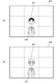
- the object recognition device 10 divides an image into a plurality of regions, and sequentially executes a recognition process of recognizing an object on the divided partial regions. Then, the object recognition device 10 scores the quality of the result of the recognition processing (recognition result), and stores the recognition result and the score in the data area 16. For example, as shown in FIG. 2, the object recognition device 10 can divide the image 20 into nine partial regions and execute the recognition processing in order from the center of the image 20.
- the numbers shown in FIG. 2 indicate the order in which the recognition processing is executed.
- the object recognition processing 10 recognizes the recognition target object based on the recognition result of the partial area having the best score.
- the number, shape and size of the partial areas and the order in which the recognition processing is performed on the partial areas are not limited to the above, and can be arbitrarily set. Also, the region where the recognition process is performed does not necessarily have to be the entire image.
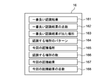
- FIG. 3 is a diagram showing details of the data area 16 of the long-term storage device 14.
- the data stored in the data area 16 includes the best recognition result 161, the score of the best recognition result 162, the location 163 where the best recognition result is obtained, the pattern 164 of the location to be recognized, the current recognition location 165, It includes the number 166 of places to be recognized, the current recognition result 167, and the score 168 of the current recognition result.
- the best recognition result 161 stores the result (recognition result) of the recognition processing executed on the partial area that has obtained the best score as a result of executing the recognition processing on each partial area.
- the recognition result includes information (position, shape, size, color, and the like) regarding the object recognized by the recognition processing.
- the best score of the recognition result 162 stores the best score among the scores of the recognition result of each partial area.
- the score of the recognition result is a value indicating the accuracy of the recognition result.
- the degree of similarity with the template can be used as the score of the recognition result.
- the score of the recognition result can be scored as 0 to 100 points according to the similarity.
- information indicating the location of the partial area having the best score among the scores of the recognition result of each partial area is stored in the location 163 where the best recognition result is obtained.
- the information indicating the location of the partial area may be coordinate information in the image of the partial area, or may be an index for identifying the partial area.
- the recognition location pattern 164 stores the location where the recognition processing is executed in each partial area and the order in which the recognition processing is executed. For example, a table such as [right, left, upper, lower, both right and left,...] May be stored in the pattern 164 of the recognized location.
- the current recognition location 165 information indicating the location of the partial area where the recognition process is being executed is stored.
- the information indicating the location of the partial area stored in the current recognition location 165 corresponds to the information stored in the location 163 where the best recognition result is obtained.
- the number 166 of recognition locations stores the total number of partial areas for which recognition processing is to be performed. For example, in the example shown in FIG. 2, the number of locations to be recognized is nine.
- the maximum value of the index is stored in the number 166 of locations to be recognized.
- the result (recognition result) of the recognition process executed for the current recognition location 165 is stored in the current recognition result 167.
- the score 168 of the current recognition result a score indicating the quality of the result of the recognition processing performed on the current recognition location 165 is stored.
- a method of recognizing the recognition target object by improving device performance (camera resolution, etc.), pasting a recognition code (such as a two-dimensional barcode) to the recognition target object A method, a method of complementing by using a plurality of sensors (sensor fusion), and the like are used.
- a method of recognizing a recognition target object by recognizing the recognition target object and objects in the vicinity of the recognition target object and comprehensively judging the recognition results of both objects may be used.
- the above-described method for improving the device performance has a problem that the cost increases.
- the method of pasting a recognition code to a recognition target object cannot be applied to a recognition target object to which the recognition code cannot be pasted.
- the method of complementing using a plurality of sensors cannot be applied to an object that is difficult to recognize with any of the sensors.
- the method of recognizing both the recognition target object and its surrounding objects to make a comprehensive judgment is performed even if the peripheral object can be recognized with high accuracy.
- the recognition rate (recognition certainty) of the recognition target object decreases.
- the recognition target object is small enough to be difficult to recognize, when it is not characteristic, when the feature amount can change, or when it can move, the recognition target object is difficult to recognize, and the recognition rate decreases.
- the recognition target when it is difficult to recognize the recognition target object due to the size, characteristics, change, movement, etc., as described above, the recognition target is used using only the recognition result of the peripheral object without using the recognition result of the recognition target object. Recognize objects.
- the object recognition method according to the present embodiment executes a process of recognizing a recognition target object from an image and a process of recognizing a peripheral object that may exist around the recognition target object from the image, and performs recognition of the recognition target object. When the result is insufficient, the recognition target object is recognized based on the recognition result of the peripheral object.
- the conventional arm robot recognizes only the beverage 211 at the center of the image, or recognizes both the beverage 211 at the center and the flower 212 at the upper right, and determines whether the object at the center of the image is the beverage to be grasped. I was judging.
- matching is performed using the feature amount of the shape and color (design and the like) of the container (pet bottle) of the beverage 211.
- the object recognition device 10 mounted on the arm robot recognizes a component to be gripped from an image captured by a camera.
- the image captured by the camera is the image 22A shown in FIG.
- the image 22A At the center of the image 22A, there is a component 221 to be grasped (recognized).
- a substrate 222 exists in a region on the right side of the component 221.
- the conventional arm robot recognizes both the component 221 at the center of the image and the substrate 222 on the right side thereof and determines whether the object at the center of the image is a component to be grasped.
- the recognition rate of the recognition target object which is the result of the comprehensive judgment, decreases.
- the recognition rate of the component 221 is further reduced by the above-described conventional recognition method. , The recognition rate of the recognition target object is further reduced.
- the recognition result of the component 221 is insufficient as described above, the recognition result of the component 221 is ignored, and the component 221 is recognized using only the recognition result of the substrate 222 that is a peripheral object. I do. That is, it is determined that the object on the left side of the substrate 222 is a component to be grasped. Thus, even if the recognition target object is too small to be easily recognized, the component 221 can be recognized as a grasp target object at a high recognition rate.
- the object recognition device 10 mounted on the vehicle recognizes a traffic signal from an image captured by a camera and performs travel control.
- the image captured by the camera is the image 23A shown in FIG.
- the image 23A At the center of the image 23A, there is a traffic signal 231 to be recognized.
- a convenience store 232 exists in the right area of the traffic light 231, and a pedestrian crossing 233 exists in a lower right area of the traffic light 231.
- the traffic signal 231 is an object that is large in size and easily recognizable, high-precision recognition is possible on a sunny day.
- the traffic light 231 cannot be recognized by the above-described conventional recognition method.
- falling snow may cause obstacles and noise, making it difficult to recognize the traffic light 231.
- It is difficult to learn snow cases because snowfall and stacking methods vary widely. In southern countries (Shikoku and Minamikyushu), snow rarely falls, making it difficult to learn.
- the recognition result of the traffic light 231 becomes insufficient as described above, the recognition result of the traffic light 231 is ignored, and only the recognition results of the convenience store 232 and the pedestrian crossing 233 as peripheral objects are used.
- the traffic light 231 is recognized. That is, the left object of the convenience store 232 is determined to be a traffic signal to be recognized, or the upper left object of the pedestrian crossing 233 is determined to be a traffic signal to be recognized.
- the traffic light 231 can be recognized as a recognition target object at a high recognition rate.
- the conventional AGV recognizes only the trash box 241 at the center of the image, or recognizes both the trash box 241 at the center and the vending machine 242 to the right of the trash box, and sets the object at the center of the image as the goal.
- matching is performed using the feature amount of the shape and color (design and the like) of the trash box 241.
- the shape is not matched by the above-described conventional recognition method. It cannot be recognized as a trash can at the goal point.
- the recognition result of the trash box 243 is insufficient as described above, the recognition result of the trash box 243 is ignored, and only the recognition result of the vending machine 242 that is a peripheral object is used. Recognize. That is, it is determined that the object on the left of the vending machine 242 is a trash can at the goal point. Thus, even when the object to be recognized has changed, the trash can 243 can be recognized as an object at the goal point with a high recognition rate.
- the chair at the goal point of the AGV when the chair at the goal point of the AGV is moved and disappears, the chair cannot be detected by the above-described conventional recognition method, so that it is determined that the recognition target object does not exist. . That is, the goal point cannot be recognized.
- the recognition result of the goal point when the recognition result of the goal point is insufficient as described above, the recognition result of the goal point is ignored, and the goal point is determined using only the recognition result of the desk 252 which is a peripheral object. I do. That is, it is determined that the left side of the desk 252 is the goal point. Thereby, even when the recognition target object moves and disappears, the goal point can be appropriately recognized.
- the object recognition device 10 When detecting a suspicious individual using a security camera, the object recognition device 10 recognizes a person to be recognized from an image captured by the camera. At this time, it is assumed that the image captured by the camera is the image 26A shown in FIG. At the center of the image 26A, there is a face 261 of a person to be recognized. In the area below the face 261, the body 262 is present. In this case, the conventional security camera recognizes only the face 261 at the center of the image, or recognizes not only the face 261 at the center but also the body 262 thereunder (both recognition), and the object at the center of the image is a suspicious individual. Was determined to be the face. When recognizing the face 261, matching is performed using features of the face 261 such as contours, part shapes, hairstyles, and beards.
- the face 263 at the center of the image wears a hat or a mask
- the feature does not match in the above-described conventional recognition method, and thus the face 263 is the face of the suspicious individual. Cannot be properly judged.
- the recognition result of the face 263 becomes insufficient as described above, the recognition result of the face 263 is ignored, and the determination of the suspicious individual is made using only the recognition result of the body 262 which is a peripheral object. I do.
- the security camera installed in the hospital wears a white coat based on the recognition result of the body 262
- it can be determined that the person is not a suspicious individual.
- the suspicious individual can be appropriately recognized.
- FIG. 10 is a flowchart illustrating an object recognition processing procedure performed by the object recognition device 10.
- step S3 the object recognition device 10 records the recognition result of step S2 in the current recognition result 167 of FIG. 3 and converts the recognition result of step S2 into a score, and the score 168 of the current recognition result of FIG. To record.
- step S4 the object recognition device 10 determines whether the score 168 of the current recognition result scored in step S3 is higher than the score 162 of the best recognition result stored in the data area 16. . That is, in step S4, the object recognition device 10 determines whether the score 168 of the current recognition result is the best score among the scores of the recognition result so far. If it is determined that the score 168 of the current recognition result is the best score, the process proceeds to step S5, and if it is determined that the score is not the best, the process proceeds to step S6.
- step S5 the object recognition device 10 stores the current recognition result 167 as the best recognition result 161. At this time, the object recognition device 10 stores the score 168 of the current recognition result as the score 162 of the best recognition result. Further, the object recognition device 10 stores the current recognition location 165 as the location 163 where the best recognition result is obtained. That is, in step S5, the object recognition device 10 records the current best value in the data area 16. In step S6, the object recognition device 10 determines whether or not the recognition processing has been performed at all the set places. Specifically, the object recognition device 10 determines whether or not the current recognition location 165 has reached the number 166 of locations to be recognized.
- step S7 If it is determined that there is a place where the recognition process has not been executed, the process proceeds to step S7, the index n is incremented, and the process returns to step S2. On the other hand, when it is determined that the recognition processing has been completed in all the set places, the process proceeds to step S8.
- the object recognition device 10 recognizes the recognition target object using the best recognition result 161. For example, when the best recognition result 161 is the recognition result of the recognition target object, the object recognition device 10 determines the location 163 where the best recognition result appears based on the recognition result of the recognition target object. It is determined that the object is a recognition target object. On the other hand, if the best recognition result 161 is not the recognition result of the recognition target object, that is, if the recognition result of the recognition target object is insufficient, the object recognition device 10 recognizes the peripheral objects of the recognition target object. The recognition target object is recognized based on the best recognition result 161 that is the result. At that time, the object recognition device 10 recognizes the recognition target object using information on the relative position between the recognition target object and the peripheral object present at the place 163 where the best recognition result is obtained.
- the recognition target object is recognized using information on the relative position between the recognition target object and the flower 212 in the upper right of the image.
- the object recognition device 10 determines that the recognition target object exists in the region at the center of the image that is the lower left region of the flower 212, and determines that the object (beverage 213) at the center of the image is the recognition target object.
- Information on the relative position between the recognition target object and the peripheral object may be any information as long as the positional relationship of the recognition target object and the peripheral object on the image can be understood, and is stored in any format such as a data table, position coordinate information, and vector information. It may be.
- the object recognition device 10 performs the recognition process on each object in the image, and recognizes the recognition target object using only the best recognition result. That is, the object recognition device 10 performs recognition processing on each of the recognition target object and its surrounding objects, and as a result, when the recognition result of the recognition target object is insufficient, based on the recognition results of the surrounding objects. Recognize the recognition target object. More specifically, the object recognition device 10 recognizes the recognition target object using only the recognition result of the peripheral object.
- the CPU 11 executes a first recognition processing unit that executes a process of recognizing a recognition target object from an image, a second recognition processing unit that executes a process of recognizing a peripheral object from an image, and If the result of the recognition by the first recognition processing unit is insufficient, it functions as an object recognition unit that recognizes the recognition target object based on the result of the recognition by the second recognition processing unit.
- the object recognition device 10 can recognize the recognition target object from the image when the recognition target object is small enough to be difficult to recognize, when it is not characteristic, when the feature amount changes, or when it moves. Even when it is difficult to directly recognize the object, it is possible to appropriately recognize the information by using information about the peripheral object that is easy to recognize.
- the recognition rate of the recognition target object can be increased.
- the accuracy (point) of the recognition result of the central recognition target object is as low as 10 points, and the accuracy (point) of the recognition result of the peripheral object (flower 212) is low. Is 100 points.
- the recognition rate can be increased as compared with the case where the recognition results of the recognition target object and the surrounding objects are comprehensively determined with the same specific gravity.
- the object recognition device 10 recognizes the recognition target object using information on the relative position between the recognition target object and the peripheral object. In other words, the object recognition device 10 determines at which position the recognition target object exists based on the peripheral object recognized with high accuracy, and determines that the recognition target object exists at the determined position. Therefore, even when the recognition target object is moving and the recognition target object does not exist in the image, it can be determined that the recognition target object exists at the position where it is determined that the recognition target object exists. As a result, even when the chair 251 set as the goal point of the AGV moves and disappears, for example, as in Case 5 shown in FIGS. 5A and 5B, the object recognition device 10 Can determine that the chair 251 which is the object to be recognized is present on the left of the desk 252. As a result, the AGV can be appropriately driven to the goal point and stopped at the goal point.
- the object recognition device 10 scores the recognition result of the recognition target object, it can easily determine whether the recognition result of the recognition target object is insufficient. Also, the best recognition result can be easily determined. As described above, the object recognition device 10 according to the present embodiment does not use the recognition result of the recognition target object (when the recognition target object is By doing so, the recognition rate of the recognition target object can be increased.
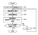
- FIG. 11 is a flowchart showing a pre-learning processing procedure executed by the object recognition device 10 prior to the object recognition processing shown in FIG.
- This pre-learning process is a process of generating and storing information on a relative position between the recognition target object and the peripheral object from an image obtained by capturing the recognition target object and the peripheral object.
- the object recognition device 10 refers to the coordinate table of the recognition location and sets a location (recognition location) where the recognition process is to be performed.
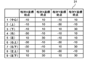
- FIG. 12 shows an example of the coordinate table of the recognition locations.
- the object recognition device 10 extracts the coordinate data of the area i from the coordinate table 31 and sets the coordinate data as the recognition location.
- step S13 the object recognition device 10 performs an object recognition process on the recognition location set in step S12, and proceeds to step S14.
- step S14 the object recognition device 10 records the result (recognition result) of the object recognition process in step S13 in the recognition data table.
- FIG. 13 shows an example of the recognition data table.
- the recognition data table 32 shown in FIG. 13 is a data table when the image 20 is divided into nine partial areas as shown in FIG.
- the data table 32 stores recognition results of the respective partial regions (region 1 (center) to region 9 (lower left)) as recognition data.
- the object recognition device 10 records the recognition result of the area i obtained in step S13 in association with the area i of the data table 32.
- step S15 the object recognition device 10 determines whether or not the recognition process has been performed at all the set locations. Specifically, the object recognition device 10 determines whether or not the current index i has reached the number of partial areas in the image (9 in FIG. 2). If it is determined that there is a place where the recognition process has not been executed, the process proceeds to step S16, the index i is incremented, and the process returns to step S12. On the other hand, if it is determined that the recognition processing has been completed in all the set places, the processing is terminated.
- the object recognition device 10 includes a storage unit that generates information on a relative position between the recognition target object and the peripheral object from an image of the recognition target object and the peripheral object, and stores the information in a storage device or the like. Can be.
- the CPU 11 can function as a storage unit. Accordingly, information on the relative position between the recognition target object and the peripheral object can be appropriately stored and used for recognition of the recognition target object.
- the pre-learning process illustrated in FIG. 11 may be executed in a device different from the object recognition device 10.
- the object recognition device 10 may obtain the result of the pre-learning process executed in the another device and use the result in the object recognition process in FIG.
- the recognition result of the recognition target object is insufficient and the recognition target object is recognized using only the recognition result of the peripheral object.
- the recognition result of the recognition target object may be recognized with some consideration instead of completely ignoring the recognition result of the recognition target object. That is, the object recognition device 10 performs weighting so that the weight of the recognition result of the recognition target object is smaller than the weight of the recognition result of the peripheral object, and the recognition result of the weighted recognition target object and the recognition result of the peripheral object. May be used to recognize the recognition target object.
- the specific gravity of the recognition result of the recognition target object may be a predetermined value such as, for example, 20%.
- the accuracy (point) of the recognition result of the central recognition target object (beverage 213) is as low as 10 points, and the accuracy (point) of the recognition result of the peripheral object (flower 212) is low.
- the specific gravity of the recognition result of the recognition target object with low accuracy may be reduced, and the recognition result of the peripheral object with high accuracy may be preferentially used.
- the recognition rate of the recognition target object can be increased as compared with the case where the recognition results of the recognition target object and the surrounding objects are comprehensively determined with the same specific gravity (formula (1)).
- the object recognition device 10 may have a function of learning information on a recognition result of a peripheral object used for recognition of a recognition target object.
- the object recognition device 10 can use the result of the learning for the process of recognizing the surrounding objects.
- the present invention can be applied to the case where the recognition target object is not at the center of the image.
- the angle of view of the camera may be controlled so that the recognition target object is located at the center of the image, and then the above-described recognition processing may be performed.
- the method of recognizing the object is fixed, but when the recognition result of the object to be recognized is insufficient, a process of recognizing the object to be recognized using a different recognition method is combined. Is also good. For example, when processing for recognizing a recognition target object based on a shape and a color is performed, if the color of the recognition target object changes, the recognition target object cannot be recognized. In such a case, the recognition method may be changed, and the recognition target object may be recognized based only on the shape. Then, when the recognition result of the recognition target object is insufficient even after changing the recognition method, the recognition target object may be recognized using the recognition result of the peripheral object.
Landscapes
- Engineering & Computer Science (AREA)
- Computer Vision & Pattern Recognition (AREA)
- Physics & Mathematics (AREA)
- General Physics & Mathematics (AREA)
- Theoretical Computer Science (AREA)
- Image Analysis (AREA)
Abstract
物体認識装置10は、画像から認識対象物体を認識する処理を実行する第1の認識処理部と、画像から認識対象物体の周辺に存在し得る周辺物体を認識する処理を実行する第2の認識処理部と、第1の認識処理部による認識結果が不十分である場合、第2の認識処理部による認識結果に基づいて、認識対象物体を認識する物体認識部と、を備える。
Description
本発明は、物体を認識する物体認識装置および物体認識方法に関する。
従来、物体を認識する物体認識装置として、画像内の認識したい対象物の特徴点を機械学習することで、対象物を高精度に認識しようとする技術が知られている。また、カメラやLiDAR(Light Detection And Ranging)、レーダーといった複数のセンサを組み合わせて対象物を認識する技術(センサフュージョン)も知られている。しかしながら、特徴点を機械学習する方法の場合、対象物が特徴的でない場合や、対象物の特徴が変化する場合には、対象物を適切に認識できない。また、センサフュージョンを用いた物体認識の場合、複数のセンサを組み合わせて使用するためコストが嵩むとともに、装置の外形寸法、重量および消費電力が増大してしまう。
認識したい対象物が認識しづらい場合の対策として、従来は、認識したい対象物だけでなく、その周辺の物体も認識し、両者の認識結果を総合的に判断することで、対象物の認識精度を向上させるようにしていた。
日本国登録公報特許第4015423号公報には、対象物の近くにある認識しやすい目印を認識し、当該目印の位置座標に対象物の相対座標を加算することで、対象物の位置座標を割り出す方法が開示されている。
日本国登録公報特許第4015423号公報には、対象物の近くにある認識しやすい目印を認識し、当該目印の位置座標に対象物の相対座標を加算することで、対象物の位置座標を割り出す方法が開示されている。
日本国登録公報特許第4015423号公報に記載の技術では、対象物の位置を割り出せても、その位置に存在する物体が認識対象の物体であるかを判断するためには、対象物自体を認識する処理が必要となる。つまり、対象物自体の認識結果と、対象物の周辺の目印の認識結果を用いて割り出された対象物の位置座標とを総合的に判断し、対象物であるかの判断が行われる。
しかしながら、対象物が小さい場合や、特徴的でない場合、形状や色等が変化した場合、さらには、対象物が移動するなどして割り出した位置に物体が存在しない場合には、対象物の認識精度が低くなる。そのため、目標の対象物かどうかの判断が困難となる。
そこで、本発明は、認識対象の物体が認識しづらい場合であっても、適切に認識対象の物体と判断することができる物体認識装置および物体認識方法を提供することを目的とする。
しかしながら、対象物が小さい場合や、特徴的でない場合、形状や色等が変化した場合、さらには、対象物が移動するなどして割り出した位置に物体が存在しない場合には、対象物の認識精度が低くなる。そのため、目標の対象物かどうかの判断が困難となる。
そこで、本発明は、認識対象の物体が認識しづらい場合であっても、適切に認識対象の物体と判断することができる物体認識装置および物体認識方法を提供することを目的とする。
上記課題を解決するために、本発明の一つの態様の物体認識装置は、画像から認識対象物体を認識する処理を実行する第1の認識処理部と、前記画像から前記認識対象物体の周辺に存在し得る周辺物体を認識する処理を実行する第2の認識処理部と、前記第1の認識処理部による認識結果が不十分である場合、前記第2の認識処理部による認識結果に基づいて、前記認識対象物体を認識する物体認識部と、を備える。
また、本発明の一つの態様の物体認識方法は、画像から認識対象物体を認識する処理を実行する第1ステップと、前記画像から前記認識対象物体の周辺に存在し得る周辺物体を認識する処理を実行する第2ステップと、前記第1ステップの認識結果が不十分である場合、前記第2ステップの認識結果に基づいて、前記認識対象物体を認識する第3ステップと、を含む。
本発明の一つの態様によれば、認識対象の物体が認識しづらい場合であっても、適切に認識対象の物体と判断することができる。
以下、図面を用いて本発明の実施の形態について説明する。
なお、本発明の範囲は、以下の実施の形態に限定されるものではなく、本発明の技術的思想の範囲内で任意に変更可能である。
なお、本発明の範囲は、以下の実施の形態に限定されるものではなく、本発明の技術的思想の範囲内で任意に変更可能である。
図1は、本実施形態における物体認識装置10のハードウェア構成例を示す図である。
本実施形態における物体認識装置10は、例えばアームロボットやAGV(無人搬送車)、自動車の自動運転やADAS(先進運転支援システム)、防犯カメラなどに搭載され、画像から認識対象物体を認識する装置である。なお、本明細書において、「認識する」とは、画像から検出された物体が、認識したい対象の物体かどうかを判断する(識別する)ことをいう。
本実施形態における物体認識装置10は、例えばアームロボットやAGV(無人搬送車)、自動車の自動運転やADAS(先進運転支援システム)、防犯カメラなどに搭載され、画像から認識対象物体を認識する装置である。なお、本明細書において、「認識する」とは、画像から検出された物体が、認識したい対象の物体かどうかを判断する(識別する)ことをいう。
例えば物体認識装置10がアームロボットに搭載されている場合、物体認識装置10は、把持対象の物体を認識する。そして、物体認識装置10による認識結果に基づいて、アームロボットのアーム動作が制御される。
また、AGVは、予め定められた走行計画に従って目標位置(ゴール地点)まで走行する。物体認識装置10がAGVに搭載されている場合には、物体認識装置10は、ゴール地点に置かれた物体を認識し、AGVは、物体認識装置10により認識された物体の位置で停止する。また、物体認識装置10は、AGVの障害物との接触を回避するために、AGVの走行経路上の障害物を認識する場合もある。
また、AGVは、予め定められた走行計画に従って目標位置(ゴール地点)まで走行する。物体認識装置10がAGVに搭載されている場合には、物体認識装置10は、ゴール地点に置かれた物体を認識し、AGVは、物体認識装置10により認識された物体の位置で停止する。また、物体認識装置10は、AGVの障害物との接触を回避するために、AGVの走行経路上の障害物を認識する場合もある。
さらに、物体認識装置10が自動車に搭載されている場合には、物体認識装置10は、歩行者や他車両等の障害物となる物体を認識する。そして、自動車は、物体認識装置10による認識結果に基づいて、障害物との接触を回避するためにブレーキ制御やステアリング制御等を行う。また、物体認識装置10は、自動車が先行車両に追従走行するために、先行車両を認識する場合もある。 また、物体認識装置10が防犯カメラに搭載されている場合には、物体認識装置10は、不審者を認識し、監視員等に報知する。
物体認識装置10は、図1に示すように、CPU11と、センサ部12と、メモリ13と、長期記憶装置14と、を備える。長期記憶装置14は、CPU11が実行するプログラムを格納するプログラム領域15と、後述する物体認識処理に用いるデータ(変数やテーブル)を格納するデータ領域16と、を備える。
CPU11は、物体認識装置10における動作を統括的に制御する。
センサ部12は、認識対象物体を撮像するカメラ(2Dカメラ、3Dカメラ等)を備える。
メモリ13は、CPU11の主メモリ、ワークエリア等として機能する。CPU11は、処理の実行に際して長期記憶装置14から必要なプログラムをメモリ13にロードし、当該プログラムを実行することで各種の機能動作を実現することができる。
センサ部12は、認識対象物体を撮像するカメラ(2Dカメラ、3Dカメラ等)を備える。
メモリ13は、CPU11の主メモリ、ワークエリア等として機能する。CPU11は、処理の実行に際して長期記憶装置14から必要なプログラムをメモリ13にロードし、当該プログラムを実行することで各種の機能動作を実現することができる。
本実施形態では、物体認識装置10は、画像から認識対象物体とその周辺に存在し得る周辺物体とをそれぞれ認識する処理を実行し、最も良い認識結果を用いて、認識対象物体を認識する。つまり、物体認識装置10は、認識対象物体の認識結果が不十分である場合には、認識対象物体の認識結果を用いず、周辺物体の認識結果のみを用いて認識対象物体を認識するようにする。
具体的には、物体認識装置10は、画像を複数の領域に分割し、分割された部分領域について、順次、物体を認識する認識処理を実行する。そして、物体認識装置10は、認識処理の結果(認識結果)の良し悪しを点数化し、認識結果およびその点数をデータ領域16に格納する。例えば、物体認識装置10は、図2に示すように、画像20を9個の部分領域に分割し、画像20の中心から順に認識処理を実行することができる。ここで、図2に示す数字は、認識処理を実行する順番を示している。そして、物体認識処理10は、最も良い点数が得られた部分領域の認識結果に基づいて、認識対象物体を認識する。
なお、部分領域の数、形状、大きさ、および、部分領域に対して認識処理を実行する順番は、上記に限定されるものではなく、任意に設定可能である。また、認識処理を実行する領域は、必ずしも画像全体でなくてもよい。
なお、部分領域の数、形状、大きさ、および、部分領域に対して認識処理を実行する順番は、上記に限定されるものではなく、任意に設定可能である。また、認識処理を実行する領域は、必ずしも画像全体でなくてもよい。
図3は、長期記憶装置14のデータ領域16の詳細を示す図である。
データ領域16に格納されるデータは、一番良い認識結果161、一番良い認識結果の点数162、一番良い認識結果が出た場所163、認識する場所のパターン164、今回の認識場所165、認識する場所の数166、今回の認識結果167および今回の認識結果の点数168を含む。
一番良い認識結果161には、各部分領域に対してそれぞれ認識処理を実行した結果、最も良い点数が得られた部分領域に対して実行された認識処理の結果(認識結果)が格納される。ここで、認識結果は、認識処理により認識された物体に関する情報(位置、形状、大きさ、色など)を含む。
データ領域16に格納されるデータは、一番良い認識結果161、一番良い認識結果の点数162、一番良い認識結果が出た場所163、認識する場所のパターン164、今回の認識場所165、認識する場所の数166、今回の認識結果167および今回の認識結果の点数168を含む。
一番良い認識結果161には、各部分領域に対してそれぞれ認識処理を実行した結果、最も良い点数が得られた部分領域に対して実行された認識処理の結果(認識結果)が格納される。ここで、認識結果は、認識処理により認識された物体に関する情報(位置、形状、大きさ、色など)を含む。
一番良い認識結果の点数162には、各部分領域の認識結果の点数のうち、最も良い点数が格納される。ここで、認識結果の点数は、認識結果の精度を示す値である。例えば、テンプレートマッチングを用いて物体の認識処理を行う場合、テンプレートとの類似度を、認識結果の点数として用いることができる。この場合、認識結果の点数は、類似度に応じて0点~100点として点数化することができる。
一番良い認識結果が出た場所163には、各部分領域の認識結果の点数のうち、最も良い点数が得られた部分領域の場所を示す情報が格納される。部分領域の場所を示す情報は、部分領域の画像内における座標情報であってもよいし、部分領域を識別するためのインデックスであってもよい。
認識する場所のパターン164には、各部分領域のうち認識処理を実行する場所、および認識処理を実行する順番が格納される。この認識する場所のパターン164には、例えば[右、左、上、下、右と左の両方、…]といったテーブルを格納してもよい。
一番良い認識結果が出た場所163には、各部分領域の認識結果の点数のうち、最も良い点数が得られた部分領域の場所を示す情報が格納される。部分領域の場所を示す情報は、部分領域の画像内における座標情報であってもよいし、部分領域を識別するためのインデックスであってもよい。
認識する場所のパターン164には、各部分領域のうち認識処理を実行する場所、および認識処理を実行する順番が格納される。この認識する場所のパターン164には、例えば[右、左、上、下、右と左の両方、…]といったテーブルを格納してもよい。
今回の認識場所165には、認識処理を実行している部分領域の場所を示す情報が格納される。この今回の認識場所165に格納される部分領域の場所を示す情報は、上述した一番良い認識結果が出た場所163に格納される情報と対応している。
認識する場所の数166には、認識処理を実行する部分領域の総数が格納される。例えば、図2に示す例では、認識する場所の数が9となる。部分領域の場所を示す情報として、部分領域を識別するためのインデックスを用いる場合、この認識する場所の数166には、上記インデックスの最大値が格納される。
今回の認識結果167には、今回の認識場所165に対して実行された認識処理の結果(認識結果)が格納される。
今回の認識結果の点数168には、今回の認識場所165に対して実行された認識処理の結果の良し悪しを示す点数が格納される。
認識する場所の数166には、認識処理を実行する部分領域の総数が格納される。例えば、図2に示す例では、認識する場所の数が9となる。部分領域の場所を示す情報として、部分領域を識別するためのインデックスを用いる場合、この認識する場所の数166には、上記インデックスの最大値が格納される。
今回の認識結果167には、今回の認識場所165に対して実行された認識処理の結果(認識結果)が格納される。
今回の認識結果の点数168には、今回の認識場所165に対して実行された認識処理の結果の良し悪しを示す点数が格納される。
従来、認識対象物体を高精度に認識するために、デバイス性能(カメラの解像度など)をアップさせて認識対象物体を認識する方法、認識対象物体に認識コード(二次元バーコードなど)を貼り付ける方法、複数のセンサを用いて補い合う方法(センサフュージョン)などが用いられている。また、認識対象物体とその周辺の物体とを認識し、両者の認識結果を総合的に判断して認識対象物体を認識する方法を用いる場合もある。
このように、認識したい物体を直接認識するか、認識したい物体の周辺物体も併せて総合的に認識する方法を用いることが一般的であった。
このように、認識したい物体を直接認識するか、認識したい物体の周辺物体も併せて総合的に認識する方法を用いることが一般的であった。
しかしながら、上記のデバイス性能をアップする方法は、コストが嵩むという問題がある。また、認識対象物体に認識コードを貼り付ける方法は、当該認識コードを貼ることができない認識対象物体には適用できない。さらに、複数のセンサを用いて補い合う方法は、いずれのセンサでも認識しづらい物体には適用できない。
また、認識対象物体とその周辺物体とを両方認識して総合的に判断する方法は、周辺物体を高精度で認識できたとしても、認識対象物体が認識しづらい場合には総合判断結果の精度が低くなり、認識対象物体の認識率(認識の確からしさ)が低下してしまう。特に、認識対象物体が、認識が困難なほど小さい場合や、特徴的でない場合、特徴量が変化し得る場合、移動し得る場合に、当該認識対象物体が認識しづらく、認識率が低下する。
また、認識対象物体とその周辺物体とを両方認識して総合的に判断する方法は、周辺物体を高精度で認識できたとしても、認識対象物体が認識しづらい場合には総合判断結果の精度が低くなり、認識対象物体の認識率(認識の確からしさ)が低下してしまう。特に、認識対象物体が、認識が困難なほど小さい場合や、特徴的でない場合、特徴量が変化し得る場合、移動し得る場合に、当該認識対象物体が認識しづらく、認識率が低下する。
本実施形態では、上記のようにサイズや特徴、変化、移動等により認識対象物体が認識しづらい場合には、認識対象物体の認識結果を用いず、周辺物体の認識結果のみを用いて認識対象物体を認識する。
つまり、本実施形態における物体認識方法は、画像から認識対象物体を認識する処理と、画像から認識対象物体の周辺に存在し得る周辺物体を認識する処理とをそれぞれ実行し、認識対象物体の認識結果が不十分である場合、周辺物体の認識結果に基づいて認識対象物体を認識する方法である。
つまり、本実施形態における物体認識方法は、画像から認識対象物体を認識する処理と、画像から認識対象物体の周辺に存在し得る周辺物体を認識する処理とをそれぞれ実行し、認識対象物体の認識結果が不十分である場合、周辺物体の認識結果に基づいて認識対象物体を認識する方法である。
以下、物体の認識事例について具体的に説明する。
(事例1)
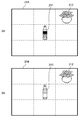
アームロボットが飲料を掴む動作を行う場合、アームロボットに搭載された物体認識装置10は、カメラによって撮像された画像から把持対象となる飲料を認識する。このとき、カメラによって撮像された画像が図4(a)に示す画像21Aであるものとする。この画像21Aの中心には、把持対象(認識対象)である飲料211が存在する。また、飲料211の右上の領域には、花212が存在する。
この場合、従来のアームロボットでは、画像中心の飲料211だけを認識する、または、中心の飲料211とその右上の花212の両方を認識して、画像中心の物体が把持対象の飲料かどうかを判断していた。なお、飲料211の認識に際しては、飲料211の容器(ペットボトル)の形状や色(デザイン等)の特徴量を用いてマッチングを行う。
(事例1)
アームロボットが飲料を掴む動作を行う場合、アームロボットに搭載された物体認識装置10は、カメラによって撮像された画像から把持対象となる飲料を認識する。このとき、カメラによって撮像された画像が図4(a)に示す画像21Aであるものとする。この画像21Aの中心には、把持対象(認識対象)である飲料211が存在する。また、飲料211の右上の領域には、花212が存在する。
この場合、従来のアームロボットでは、画像中心の飲料211だけを認識する、または、中心の飲料211とその右上の花212の両方を認識して、画像中心の物体が把持対象の飲料かどうかを判断していた。なお、飲料211の認識に際しては、飲料211の容器(ペットボトル)の形状や色(デザイン等)の特徴量を用いてマッチングを行う。
ところが、図4(b)に示すように、アームロボットの把持対象として、飲料211とはデザインの異なる飲料213が投入された場合、上記従来の認識方法では、色がマッチングしないため、飲料213を把持対象の飲料として認識することができない。
本実施形態では、上記のように飲料213の認識結果が不十分となる場合には、飲料213の認識結果を無視し、周辺物体である花212の認識結果のみを用いて、飲料213を認識する。つまり、花212の左下の物体は把持対象の飲料であると判断する。これにより、認識対象物体に変化が生じている場合であっても、飲料213を把持対象の物体として高い認識率で認識することができる。
本実施形態では、上記のように飲料213の認識結果が不十分となる場合には、飲料213の認識結果を無視し、周辺物体である花212の認識結果のみを用いて、飲料213を認識する。つまり、花212の左下の物体は把持対象の飲料であると判断する。これにより、認識対象物体に変化が生じている場合であっても、飲料213を把持対象の物体として高い認識率で認識することができる。
(事例2)
アームロボットが基板に実装する部品(半導体等)を掴む動作を行う場合、アームロボットに搭載された物体認識装置10は、カメラによって撮像された画像から把持対象となる部品を認識する。このとき、カメラによって撮像された画像が図5(a)に示す画像22Aであるものとする。この画像22Aの中心には、把持対象(認識対象)である部品221が存在する。また、部品221の右の領域には、基板222が存在する。
この場合、従来のアームロボットでは、画像中心の部品221とその右の基板222の両方を認識して、画像中心の物体が把持対象の部品であるかを判断していた。ところが、把持対象である部品211は小さくて認識しづらいため、総合判断の結果である認識対象物体の認識率が低下してしまう。
アームロボットが基板に実装する部品(半導体等)を掴む動作を行う場合、アームロボットに搭載された物体認識装置10は、カメラによって撮像された画像から把持対象となる部品を認識する。このとき、カメラによって撮像された画像が図5(a)に示す画像22Aであるものとする。この画像22Aの中心には、把持対象(認識対象)である部品221が存在する。また、部品221の右の領域には、基板222が存在する。
この場合、従来のアームロボットでは、画像中心の部品221とその右の基板222の両方を認識して、画像中心の物体が把持対象の部品であるかを判断していた。ところが、把持対象である部品211は小さくて認識しづらいため、総合判断の結果である認識対象物体の認識率が低下してしまう。
また、図5(b)に示すように、画像中心の部品221の近傍にゴミ223が存在する場合、上記従来の認識方法では、部品221の認識率がさらに低下するために、総合判断の結果である認識対象物体の認識率がさらに低下してしまう。
本実施形態では、上記のように部品221の認識結果が不十分となる場合には、部品221の認識結果を無視し、周辺物体である基板222の認識結果のみを用いて、部品221を認識する。つまり、基板222の左の物体は把持対象の部品であると判断する。これにより、認識対象物体が認識しづらいほど小さい場合であっても、部品221を把持対象の物体として高い認識率で認識することができる。
本実施形態では、上記のように部品221の認識結果が不十分となる場合には、部品221の認識結果を無視し、周辺物体である基板222の認識結果のみを用いて、部品221を認識する。つまり、基板222の左の物体は把持対象の部品であると判断する。これにより、認識対象物体が認識しづらいほど小さい場合であっても、部品221を把持対象の物体として高い認識率で認識することができる。
(事例3)
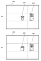
自動運転やADASが搭載された自動車が走行する場合、自動車に搭載された物体認識装置10は、カメラによって撮像された画像から信号機を認識し、走行制御を行う。このとき、カメラによって撮像された画像が図6(a)に示す画像23Aであるものとする。この画像23Aの中心には、認識対象である信号機231が存在する。また、信号機231の右の領域には、コンビニ232が存在し、信号機231の右下の領域には、横断歩道233が存在する。
この場合、従来の自動車では、画像中心の信号機231のみ、または、中心の信号機231と右のコンビニ232、または、中心の信号機231と右下の横断歩道233、または、中心の信号機231と右のコンビニ232と右下の横断歩道233を認識して、画像中心の物体が認識対象の信号機であるかを判断していた。
自動運転やADASが搭載された自動車が走行する場合、自動車に搭載された物体認識装置10は、カメラによって撮像された画像から信号機を認識し、走行制御を行う。このとき、カメラによって撮像された画像が図6(a)に示す画像23Aであるものとする。この画像23Aの中心には、認識対象である信号機231が存在する。また、信号機231の右の領域には、コンビニ232が存在し、信号機231の右下の領域には、横断歩道233が存在する。
この場合、従来の自動車では、画像中心の信号機231のみ、または、中心の信号機231と右のコンビニ232、または、中心の信号機231と右下の横断歩道233、または、中心の信号機231と右のコンビニ232と右下の横断歩道233を認識して、画像中心の物体が認識対象の信号機であるかを判断していた。
信号機231は、サイズも大きく認識しやすい物体であるため、晴れた日には高精度な認識が可能である。ところが、図6(b)に示すように、雪234により信号機231が覆われてしまうと、上記従来の認識方法では、信号機231を認識することができない。また、降る雪が障害物やノイズの原因となり、信号機231を認識しづらくする場合もある。
雪のケースを学習させるにも、雪の降り方や積もり方は千差万別である、南国(四国や南九州)だと滅多に雪が降らないため、学習させるのが困難である。
雪のケースを学習させるにも、雪の降り方や積もり方は千差万別である、南国(四国や南九州)だと滅多に雪が降らないため、学習させるのが困難である。
本実施形態では、上記のように信号機231の認識結果が不十分となる場合には、信号機231の認識結果を無視し、周辺物体であるコンビニ232や横断歩道233の認識結果のみを用いて、信号機231を認識する。つまり、コンビニ232の左の物体は認識対象の信号機であると判断する、もしくは、横断歩道233の左上の物体は認識対象の信号機であると判断する。これにより、認識対象物体に変化が生じたり障害物やノイズが生じたりしている場合であっても、信号機231を認識対象の物体として高い認識率で認識することができる。
(事例4)
AGVが自動販売機の横に設置されたゴミ箱をゴールとして移動する場合、AGVに搭載された物体認識装置10は、カメラによって撮像された画像からゴールとなるゴミ箱を認識する。このとき、カメラによって撮像された画像が図7(a)に示す画像24Aであるものとする。この画像24Aの中心には、ゴール(認識対象)であるゴミ箱241が存在する。また、ゴミ箱241の右の領域には、自動販売機242が存在する。
この場合、従来のAGVでは、画像中心のゴミ箱241だけを認識する、または、中心のゴミ箱241とその右の自動販売機242の両方を認識して、画像中心の物体がゴールとして設定されたゴミ箱であるかを判断していた。なお、ゴミ箱241の認識に際しては、ゴミ箱241の形状や色(デザイン等)の特徴量を用いてマッチングを行う。
AGVが自動販売機の横に設置されたゴミ箱をゴールとして移動する場合、AGVに搭載された物体認識装置10は、カメラによって撮像された画像からゴールとなるゴミ箱を認識する。このとき、カメラによって撮像された画像が図7(a)に示す画像24Aであるものとする。この画像24Aの中心には、ゴール(認識対象)であるゴミ箱241が存在する。また、ゴミ箱241の右の領域には、自動販売機242が存在する。
この場合、従来のAGVでは、画像中心のゴミ箱241だけを認識する、または、中心のゴミ箱241とその右の自動販売機242の両方を認識して、画像中心の物体がゴールとして設定されたゴミ箱であるかを判断していた。なお、ゴミ箱241の認識に際しては、ゴミ箱241の形状や色(デザイン等)の特徴量を用いてマッチングを行う。
ところが、図7(b)に示すように、AGVのゴール地点のゴミ箱が、ゴミ箱241とは形状の異なるゴミ箱243に入れ替わった場合、上記従来の認識方法では、形状がマッチングしないため、ゴミ箱243をゴール地点のゴミ箱として認識することができない。
本実施形態では、上記のようにゴミ箱243の認識結果が不十分となる場合には、ゴミ箱243の認識結果を無視し、周辺物体である自動販売機242の認識結果のみを用いて、ゴミ箱243を認識する。つまり、自動販売機242の左の物体はゴール地点のゴミ箱であると判断する。これにより、認識対象物体に変化が生じている場合であっても、ゴミ箱243をゴール地点の物体として高い認識率で認識することができる。
本実施形態では、上記のようにゴミ箱243の認識結果が不十分となる場合には、ゴミ箱243の認識結果を無視し、周辺物体である自動販売機242の認識結果のみを用いて、ゴミ箱243を認識する。つまり、自動販売機242の左の物体はゴール地点のゴミ箱であると判断する。これにより、認識対象物体に変化が生じている場合であっても、ゴミ箱243をゴール地点の物体として高い認識率で認識することができる。
(事例5)
AGVが椅子をゴールとして移動する場合、AGVに搭載された物体認識装置10は、カメラによって撮像された画像からゴールとなる椅子を認識する。このとき、カメラによって撮像された画像が図8(a)に示す画像25Aであるものとする。この画像25Aの中心には、ゴール(認識対象)である椅子251が存在する。また、椅子251の右の領域には、机252が存在する。
この場合、従来のAGVでは、画像中心の椅子251だけを認識する、または、中心の椅子251とその右の机252の両方を認識して、画像中心の物体がゴールとして設定された椅子であるかを判断していた。
AGVが椅子をゴールとして移動する場合、AGVに搭載された物体認識装置10は、カメラによって撮像された画像からゴールとなる椅子を認識する。このとき、カメラによって撮像された画像が図8(a)に示す画像25Aであるものとする。この画像25Aの中心には、ゴール(認識対象)である椅子251が存在する。また、椅子251の右の領域には、机252が存在する。
この場合、従来のAGVでは、画像中心の椅子251だけを認識する、または、中心の椅子251とその右の机252の両方を認識して、画像中心の物体がゴールとして設定された椅子であるかを判断していた。
ところが、図8(b)に示すように、AGVのゴール地点の椅子が移動され、無くなってしまった場合、上記従来の認識方法では、椅子を検出できないため、認識対象物体が存在しないと判断する。つまり、ゴール地点の認識ができない。
本実施形態では、上記のようにゴール地点の認識結果が不十分となる場合には、ゴール地点の認識結果を無視し、周辺物体である机252の認識結果のみを用いて、ゴール地点を判断する。つまり、机252の左はゴール地点であると判断する。これにより、認識対象物体が移動して無くなった場合であっても、適切にゴール地点を認識することができる。
本実施形態では、上記のようにゴール地点の認識結果が不十分となる場合には、ゴール地点の認識結果を無視し、周辺物体である机252の認識結果のみを用いて、ゴール地点を判断する。つまり、机252の左はゴール地点であると判断する。これにより、認識対象物体が移動して無くなった場合であっても、適切にゴール地点を認識することができる。
(事例6)
防犯カメラを用いて不審者を検知する場合、物体認識装置10は、カメラによって撮像された画像から認識対象となる人物を認識する。このとき、カメラによって撮像された画像が図9(a)に示す画像26Aであるものとする。この画像26Aの中心には、認識対象である人物の顔261が存在する。また、顔261の下の領域には、身体262が存在する。
この場合、従来の防犯カメラでは、画像中心の顔261だけを認識する、または、中心の顔261だけでなく、その下の身体262も認識(両方認識)して、画像中心の物体が不審者の顔であるかを判断していた。なお、顔261の認識に際しては、顔261の輪郭、パーツの形状、髪型、髭などの特徴量を用いてマッチングを行う。
防犯カメラを用いて不審者を検知する場合、物体認識装置10は、カメラによって撮像された画像から認識対象となる人物を認識する。このとき、カメラによって撮像された画像が図9(a)に示す画像26Aであるものとする。この画像26Aの中心には、認識対象である人物の顔261が存在する。また、顔261の下の領域には、身体262が存在する。
この場合、従来の防犯カメラでは、画像中心の顔261だけを認識する、または、中心の顔261だけでなく、その下の身体262も認識(両方認識)して、画像中心の物体が不審者の顔であるかを判断していた。なお、顔261の認識に際しては、顔261の輪郭、パーツの形状、髪型、髭などの特徴量を用いてマッチングを行う。
ところが、図9(b)に示すように、画像中心の顔263が帽子やマスクを着用している場合、上記従来の認識方法では、特徴がマッチングしないため、顔263が不審者の顔であるかを適切に判断することができない。
本実施形態では、上記のように顔263の認識結果が不十分となる場合には、顔263の認識結果を無視し、周辺物体である身体262の認識結果のみを用いて、不審者の判断を行う。例えば、病院内に設置された防犯カメラにおいて、身体262の認識結果により白衣を着用していると判断された場合には、不審者ではないと判断することができる。このように、認識対象物体に変化が生じている場合であっても、適切に不審者を認識することができる。
本実施形態では、上記のように顔263の認識結果が不十分となる場合には、顔263の認識結果を無視し、周辺物体である身体262の認識結果のみを用いて、不審者の判断を行う。例えば、病院内に設置された防犯カメラにおいて、身体262の認識結果により白衣を着用していると判断された場合には、不審者ではないと判断することができる。このように、認識対象物体に変化が生じている場合であっても、適切に不審者を認識することができる。
図10は、物体認識装置10が実行する物体認識処理手順を示すフローチャートである。
まずステップS1において、物体認識装置10は、長期記憶装置14のデータ領域16に格納された認識結果を初期化する。具体的には、図3に示す一番良い認識結果161、一番良い認識結果の点数162および一番良い認識結果が出た場所163の変数に、それぞれ予め設定された初期値を代入する。また、今回の認識場所165を示す変数nを初期値(n=1)に設定する。
次にステップS2において、物体認識装置10は、センサ部12から画像を取得し、今回の認識場所に対して物体認識処理を施す。例えばn=1である場合、図2に示す画像20の中心の領域が今回の認識場所となり、物体認識装置10は、画像の中心の領域に対して認識処理を行う。
まずステップS1において、物体認識装置10は、長期記憶装置14のデータ領域16に格納された認識結果を初期化する。具体的には、図3に示す一番良い認識結果161、一番良い認識結果の点数162および一番良い認識結果が出た場所163の変数に、それぞれ予め設定された初期値を代入する。また、今回の認識場所165を示す変数nを初期値(n=1)に設定する。
次にステップS2において、物体認識装置10は、センサ部12から画像を取得し、今回の認識場所に対して物体認識処理を施す。例えばn=1である場合、図2に示す画像20の中心の領域が今回の認識場所となり、物体認識装置10は、画像の中心の領域に対して認識処理を行う。
次にステップS3では、物体認識装置10は、ステップS2の認識結果を図3の今回の認識結果167に記録するとともに、ステップS2の認識結果を点数化し、図3の今回の認識結果の点数168に記録する。
ステップS4では、物体認識装置10は、ステップS3において採点された今回の認識結果の点数168が、データ領域16に格納されている一番良い認識結果の点数162よりも高いか否かを判定する。つまり、このステップS4では、物体認識装置10は、今回の認識結果の点数168が、これまでの認識結果の点数の中で最も良い点数であるか否かを判定する。そして、今回の認識結果の点数168が最も良い点数であると判定された場合にはステップS5に移行し、最も良い点数ではないと判定された場合にはステップS6に移行する。
ステップS4では、物体認識装置10は、ステップS3において採点された今回の認識結果の点数168が、データ領域16に格納されている一番良い認識結果の点数162よりも高いか否かを判定する。つまり、このステップS4では、物体認識装置10は、今回の認識結果の点数168が、これまでの認識結果の点数の中で最も良い点数であるか否かを判定する。そして、今回の認識結果の点数168が最も良い点数であると判定された場合にはステップS5に移行し、最も良い点数ではないと判定された場合にはステップS6に移行する。
ステップS5では、物体認識装置10は、今回の認識結果167を、一番良い認識結果161として格納する。また、このとき物体認識装置10は、今回の認識結果の点数168を、一番良い認識結果の点数162として格納する。さらに、物体認識装置10は、今回の認識場所165を、一番良い認識結果が出た場所163として格納する。つまり、このステップS5において、物体認識装置10は、データ領域16に現時点での最良値を記録する。
ステップS6では、物体認識装置10は、設定されたすべての場所で認識処理を実行したか否かを判定する。具体的には、物体認識装置10は、今回の認識場所165が認識する場所の数166に達しているか否かを判定する。そして、まだ認識処理を実行していない場所が存在すると判定された場合にはステップS7に移行し、インデックスnをインクリメントしてステップS2に戻る。一方、設定されたすべての場所で認識処理が完了していると判定された場合にはステップS8に移行する。
ステップS6では、物体認識装置10は、設定されたすべての場所で認識処理を実行したか否かを判定する。具体的には、物体認識装置10は、今回の認識場所165が認識する場所の数166に達しているか否かを判定する。そして、まだ認識処理を実行していない場所が存在すると判定された場合にはステップS7に移行し、インデックスnをインクリメントしてステップS2に戻る。一方、設定されたすべての場所で認識処理が完了していると判定された場合にはステップS8に移行する。
ステップS8では、物体認識装置10は、一番良い認識結果161を用いて、認識対象物体を認識する。例えば、一番良い認識結果161が認識対象物体の認識結果である場合には、物体認識装置10は、当該認識対象物体の認識結果をもとに、一番良い認識結果が出た場所163の物体が認識対象物体であると判断する。
一方、一番良い認識結果161が認識対象物体の認識結果ではない場合、すなわち、認識対象物体の認識結果が不十分である場合には、物体認識装置10は、認識対象物体の周辺物体の認識結果である一番良い認識結果161をもとに、認識対象物体を認識する。その際、物体認識装置10は、認識対象物体と、一番良い認識結果が出た場所163に存在する周辺物体との相対位置に関する情報を用いて、認識対象物体を認識する。
一方、一番良い認識結果161が認識対象物体の認識結果ではない場合、すなわち、認識対象物体の認識結果が不十分である場合には、物体認識装置10は、認識対象物体の周辺物体の認識結果である一番良い認識結果161をもとに、認識対象物体を認識する。その際、物体認識装置10は、認識対象物体と、一番良い認識結果が出た場所163に存在する周辺物体との相対位置に関する情報を用いて、認識対象物体を認識する。
例えば上述した事例1(図4(b))の場合、画像中心の飲料213の認識結果が不十分となり、画像右上で一番良い認識結果が得られる。この場合には、認識対象物体と画像右上の花212との相対位置に関する情報を用いて、認識対象物体を認識する。この図4(b)に示す例では、事前に認識対象物体が花212の左下の領域に存在することがわかっている。そのため、物体認識装置10は、花212の左下の領域である画像中心の領域に認識対象物体が存在すると判断し、画像中心の物体(飲料213)が認識対象物体であると判断する。 認識対象物体と周辺物体との相対位置に関する情報は、認識対象物体と周辺物体との画像上における位置関係がわかる情報であればよく、データテーブル、位置座標情報、ベクトル情報など、いずれ形式で記憶されていてもよい。
このように、物体認識装置10は、画像内の物体に対してそれぞれ認識処理を行い、最も良い認識結果だけを用いて認識対象物体を認識する。つまり、物体認識装置10は、認識対象物体とその周辺物体との各々について認識処理を行い、その結果、認識対象物体の認識結果が不十分である場合には、周辺物体の認識結果に基づいて認識対象物体を認識する。より具体的には、物体認識装置10は、周辺物体の認識結果のみを用いて、認識対象物体を認識する。
なお、本実施形態では、CPU11が、画像から認識対象物体を認識する処理を実行する第1の認識処理部、画像から周辺物体を認識する処理を実行する第2の認識処理部、および、第1の認識処理部による認識結果が不十分である場合、第2の認識処理部による認識結果に基づいて認識対象物体を認識する物体認識部として機能する。
なお、本実施形態では、CPU11が、画像から認識対象物体を認識する処理を実行する第1の認識処理部、画像から周辺物体を認識する処理を実行する第2の認識処理部、および、第1の認識処理部による認識結果が不十分である場合、第2の認識処理部による認識結果に基づいて認識対象物体を認識する物体認識部として機能する。
上記構成により、本実施形態における物体認識装置10は、認識対象物体が、認識が困難なほど小さい場合や、特徴的でない場合、特徴量が変化した場合、移動した場合など、画像から認識対象物体を直接認識しづらい場合であっても、認識しやすい周辺物体に関する情報を用いて適切に認識することができる。また、精度の低い認識対象物体の認識結果を用いずに、精度の高い周辺物体の認識結果のみを用いるので、認識対象物体と周辺物体との認識結果を総合的に判断する場合と比較して、認識対象物体の認識率を上げることができる。
例えば図4(b)に示す事例1の場合、中心の認識対象物体(飲料213)の認識結果の精度(点数)が10点と低く、周辺物体(花212)の認識結果の精度(点数)が100点である場合について考える。
認識対象物体と周辺物体との認識結果を総合的に判断する場合、認識対象物体の認識率は次式により表される。
(10点×50%)+(100点×50%)=55点 ………(1)
これに対して、本実施形態のように、精度の低い認識対象物体の認識結果を用いずに、精度の高い周辺物体の認識結果のみを用いた場合、認識対象物体の認識率は次式により表される。
(10点×0%)+(100点×100%)=100点 ………(2)
このように、認識対象物体と周辺物体との認識結果を同等の比重で総合的に判断する場合と比較して、認識率を上げることができる。
認識対象物体と周辺物体との認識結果を総合的に判断する場合、認識対象物体の認識率は次式により表される。
(10点×50%)+(100点×50%)=55点 ………(1)
これに対して、本実施形態のように、精度の低い認識対象物体の認識結果を用いずに、精度の高い周辺物体の認識結果のみを用いた場合、認識対象物体の認識率は次式により表される。
(10点×0%)+(100点×100%)=100点 ………(2)
このように、認識対象物体と周辺物体との認識結果を同等の比重で総合的に判断する場合と比較して、認識率を上げることができる。
また、物体認識装置10は、認識対象物体が認識しづらい場合、認識対象物体と周辺物体との相対位置に関する情報を用いて、認識対象物体を認識する。つまり、物体認識装置10は、高精度に認識された周辺物体を基準としてどの位置に認識対象物体が存在するかを判断し、判断された位置に認識対象物体が存在すると判断する。したがって、認識対象物体が移動しており、画像内に認識対象物体が存在しない場合であっても、認識対象物体が存在すると判断された位置に認識対象物体が存在すると判断することができる。
これにより、例えば図5(a)および図5(b)に示す事例5のように、AGVのゴール地点として設定された椅子251が移動し、無くなっている場合であっても、物体認識装置10は、机252の左に認識対象物体である椅子251が存在すると判断することができる。その結果、AGVを適切にゴール地点まで走行させ、当該ゴール地点で停止させることができる。
これにより、例えば図5(a)および図5(b)に示す事例5のように、AGVのゴール地点として設定された椅子251が移動し、無くなっている場合であっても、物体認識装置10は、机252の左に認識対象物体である椅子251が存在すると判断することができる。その結果、AGVを適切にゴール地点まで走行させ、当該ゴール地点で停止させることができる。
また、物体認識装置10は、認識対象物体の認識結果を点数化するので、認識対象物体の認識結果が不十分であるか否かを容易に判定することができる。また、最も良い認識結果を容易に判定することもできる。
以上のように、本実施形態における物体認識装置10は、認識対象物体を認識しようとすることが、むしろデメリットになっている場合には、認識対象物体の認識結果を用いない(認識対象物体を認識しない)ようにすることで、認識対象物体の認識率を上げることができる。
以上のように、本実施形態における物体認識装置10は、認識対象物体を認識しようとすることが、むしろデメリットになっている場合には、認識対象物体の認識結果を用いない(認識対象物体を認識しない)ようにすることで、認識対象物体の認識率を上げることができる。
図11は、物体認識装置10が、図10に示す物体認識処理に先立って実行する事前学習処理手順を示すフローチャートである。この事前学習処理は、認識対象物体と周辺物体とを撮像した画像から、認識対象物体と周辺物体との相対位置に関する情報を生成し、記憶する処理である。
まずステップS11において、物体認識装置10は、インデックスiを初期化(i=1)し、ステップS12に移行する。
ステップS12では、物体認識装置10は、認識場所の座標テーブルを参照し、認識処理を実行する場所(認識場所)を設定する。認識場所の座標テーブルの一例を図12に示す。この図12に示す認識場所の座標テーブル31は、図2に示すように画像20を9個の部分領域に分割した場合の座標テーブルである。座標テーブル31は、各部分領域(領域1(中心)~領域9(左下))の画像上の座標位置を格納する。各部分領域の座標位置は、画像の中央を基準とした相対XY座標で示されている。
物体認識装置10は、座標テーブル31から領域iの座標データを取り出し、認識場所として設定する。
まずステップS11において、物体認識装置10は、インデックスiを初期化(i=1)し、ステップS12に移行する。
ステップS12では、物体認識装置10は、認識場所の座標テーブルを参照し、認識処理を実行する場所(認識場所)を設定する。認識場所の座標テーブルの一例を図12に示す。この図12に示す認識場所の座標テーブル31は、図2に示すように画像20を9個の部分領域に分割した場合の座標テーブルである。座標テーブル31は、各部分領域(領域1(中心)~領域9(左下))の画像上の座標位置を格納する。各部分領域の座標位置は、画像の中央を基準とした相対XY座標で示されている。
物体認識装置10は、座標テーブル31から領域iの座標データを取り出し、認識場所として設定する。
次にステップS13では、物体認識装置10は、ステップS12において設定された認識場所に対して物体認識処理を実行し、ステップS14に移行する。
ステップS14では、物体認識装置10は、ステップS13における物体認識処理の結果(認識結果)を、認識用データテーブルに記録する。認識用データテーブルの一例を図13に示す。この図13に示す認識用データテーブル32は、図2に示すように画像20を9個の部分領域に分割した場合のデータテーブルである。データテーブル32は、各部分領域(領域1(中心)~領域9(左下))の認識結果を、それぞれ認識用データとして格納する。
物体認識装置10は、ステップS13において得られた領域iの認識結果を、データテーブル32の領域iに対応付けて記録する。
ステップS14では、物体認識装置10は、ステップS13における物体認識処理の結果(認識結果)を、認識用データテーブルに記録する。認識用データテーブルの一例を図13に示す。この図13に示す認識用データテーブル32は、図2に示すように画像20を9個の部分領域に分割した場合のデータテーブルである。データテーブル32は、各部分領域(領域1(中心)~領域9(左下))の認識結果を、それぞれ認識用データとして格納する。
物体認識装置10は、ステップS13において得られた領域iの認識結果を、データテーブル32の領域iに対応付けて記録する。
次にステップS15では、物体認識装置10は、設定されたすべての場所で認識処理を実行したか否かを判定する。具体的には、物体認識装置10は、現在のインデックスiが画像中の部分領域の数(図2では、9)に達しているか否かを判定する。そして、まだ認識処理を実行していない場所が存在すると判定された場合にはステップS16に移行し、インデックスiをインクリメントしてステップS12に戻る。一方、設定されたすべての場所で認識処理が完了していると判定された場合には処理を終了する。
このように、物体認識装置10は、認識対象物体と周辺物体とを撮像した画像から、認識対象物体と周辺物体との相対位置に関する情報を生成し、記憶装置等に記憶する記憶部を備えることができる。本実施形態では、CPU11が記憶部として機能することができる。
これにより、認識対象物体と周辺物体との相対位置に関する情報を適切に記憶し、認識対象物体の認識に用いることができる。
これにより、認識対象物体と周辺物体との相対位置に関する情報を適切に記憶し、認識対象物体の認識に用いることができる。
なお、図11に示す事前学習処理は、物体認識装置10とは別の装置において実行されてもよい。その場合、物体認識装置10は、当該別の装置において実行された事前学習処理の結果を取得し、図10の物体認識処理に使用すればよい。
(変形例)
上記実施形態においては、認識対象物体の認識結果が不十分である場合、周辺物体の認識結果のみを用いて認識対象物体を認識する場合について説明した。しかしながら、認識対象物体の認識結果が不十分である場合、認識対象物体の認識結果を完全に無視するのではなく、多少は考慮して認識対象物体を認識するようにしてもよい。つまり、物体認識装置10は、認識対象物体の認識結果の重みを、周辺物体の認識結果の重みよりも小さくする重み付けを行い、当該重み付けを行った認識対象物体の認識結果と周辺物体の認識結果とに基づいて、認識対象物体を認識してもよい。
上記実施形態においては、認識対象物体の認識結果が不十分である場合、周辺物体の認識結果のみを用いて認識対象物体を認識する場合について説明した。しかしながら、認識対象物体の認識結果が不十分である場合、認識対象物体の認識結果を完全に無視するのではなく、多少は考慮して認識対象物体を認識するようにしてもよい。つまり、物体認識装置10は、認識対象物体の認識結果の重みを、周辺物体の認識結果の重みよりも小さくする重み付けを行い、当該重み付けを行った認識対象物体の認識結果と周辺物体の認識結果とに基づいて、認識対象物体を認識してもよい。
この場合、認識対象物体の認識結果の比重は、例えば20%など、予め決められた値であってよい。例えば図4(b)に示す事例1の場合、中心の認識対象物体(飲料213)の認識結果の精度(点数)が10点と低く、周辺物体(花212)の認識結果の精度(点数)が100点である場合、認識対象物体の認識率は次式により表される。
(10点×20%)+(100点×80%)=82点 ………(3)
このように、精度の低い認識対象物体の認識結果の比重を下げ、精度の高い周辺物体の認識結果を優先的に用いてもよい。この場合にも、認識対象物体と周辺物体との認識結果を同等の比重で総合的に判断する場合(上記(1)式)と比較して、認識対象物体の認識率を上げることができる。
(10点×20%)+(100点×80%)=82点 ………(3)
このように、精度の低い認識対象物体の認識結果の比重を下げ、精度の高い周辺物体の認識結果を優先的に用いてもよい。この場合にも、認識対象物体と周辺物体との認識結果を同等の比重で総合的に判断する場合(上記(1)式)と比較して、認識対象物体の認識率を上げることができる。
また、上記実施形態においては、物体認識装置10は、認識対象物体の認識に用いた周辺物体の認識結果に関する情報を学習する機能を有していてもよい。この場合、物体認識装置10は、学習の結果を、周辺物体を認識する処理に用いることができる。 このように、高精度に認識できた周辺物体に関する情報を学習することで、例えば、次回以降は高精度に認識できた周辺物体を優先的に認識する処理を行うといった対応が可能となる。これにより、処理負荷を軽減しつつ、適切に認識対象物体を認識することができる。
さらに、上記実施形態においては、認識対象物体が画像の中心に位置する場合について説明したが、認識対象物体が画像の中心に無い場合にも適用可能である。なお、認識対象物体が画像の中心に無い場合、カメラの画角を制御して、認識対象物体が画像の中心に位置するようにしてから上述した認識処理を行うようにしてもよい。
また、上記実施形態においては、物体の認識方法は固定であるが、認識対象物体の認識結果が不十分である場合には、異なる認識方法を用いて認識対象物体を認識するといった処理を組み合わせてもよい。
例えば、認識対象物体を形状および色に基づいて認識する処理を行っている場合、認識対象物体の色が変化すると当該認識対象物体を認識できなくなる。このような場合には、認識方法を変更し、認識対象物体を形状のみに基づいて認識するようにしてもよい。そして、認識方法を変更しても認識対象物体の認識結果が不十分である場合に、周辺物体の認識結果を用いて認識対象物体を認識するようにしてもよい。
例えば、認識対象物体を形状および色に基づいて認識する処理を行っている場合、認識対象物体の色が変化すると当該認識対象物体を認識できなくなる。このような場合には、認識方法を変更し、認識対象物体を形状のみに基づいて認識するようにしてもよい。そして、認識方法を変更しても認識対象物体の認識結果が不十分である場合に、周辺物体の認識結果を用いて認識対象物体を認識するようにしてもよい。
10…物体認識装置、11…CPU、12…センサ部、13…メモリ、14…長期記憶装置、16…データ領域、20…画像
Claims (8)
- 画像から認識対象物体を認識する処理を実行する第1の認識処理部と、
前記画像から前記認識対象物体の周辺に存在し得る周辺物体を認識する処理を実行する第2の認識処理部と、
前記第1の認識処理部による認識結果が不十分である場合、前記第2の認識処理部による認識結果に基づいて、前記認識対象物体を認識する物体認識部と、を備えることを特徴とする物体認識装置。 - 前記物体認識部は、
前記第2の認識処理部による認識結果のみを用いて、前記認識対象物体を認識することを特徴とする請求項1に記載の物体認識装置。 - 前記物体認識部は、
前記第1の認識処理部による認識結果の重みを前記第2の認識処理部による認識結果の重みよりも小さくする重み付けを行い、
当該重み付けを行った前記第1の認識処理部による認識結果および前記第2の認識処理部による認識結果に基づいて、前記認識対象物体を認識することを特徴とする請求項1に記載の物体認識装置。 - 前記物体認識部は、
前記第2の認識処理部により認識された前記周辺物体に関する情報に基づいて、前記認識対象物体と前記周辺物体との相対位置に関する情報を用いて、前記認識対象物体を認識することを特徴とする請求項1から3のいずれか1項に記載の物体認識装置。 - 前記認識対象物体と前記周辺物体とを撮像した画像から、前記認識対象物体と前記周辺物体との相対位置に関する情報を生成し、記憶する記憶部をさらに備えることを特徴とする請求項4に記載の物体認識装置。
- 前記第1の認識処理部は、前記認識対象物体の認識結果を点数化することを特徴とする請求項1から5のいずれか1項に記載の物体認識装置。
- 前記物体認識部による前記認識対象物体の認識に用いた前記第2の認識処理部による認識結果に関する情報を学習し、当該学習の結果を、前記第2の認識処理部による前記周辺物体を認識する処理に用いることを特徴とする請求項1から6のいずれか1項に記載の物体認識装置。
- 画像から認識対象物体を認識する処理を実行する第1ステップと、
前記画像から前記認識対象物体の周辺に存在し得る周辺物体を認識する処理を実行する第2ステップと、
前記第1ステップの認識結果が不十分である場合、前記第2ステップの認識結果に基づいて、前記認識対象物体を認識する第3ステップと、を含むことを特徴とする物体認識方法。
Applications Claiming Priority (2)
| Application Number | Priority Date | Filing Date | Title |
|---|---|---|---|
| JP2018-165964 | 2018-09-05 | ||
| JP2018165964 | 2018-09-05 |
Publications (1)
| Publication Number | Publication Date |
|---|---|
| WO2020049933A1 true WO2020049933A1 (ja) | 2020-03-12 |
Family
ID=69722812
Family Applications (1)
| Application Number | Title | Priority Date | Filing Date |
|---|---|---|---|
| PCT/JP2019/030941 Ceased WO2020049933A1 (ja) | 2018-09-05 | 2019-08-06 | 物体認識装置および物体認識方法 |
Country Status (1)
| Country | Link |
|---|---|
| WO (1) | WO2020049933A1 (ja) |
Cited By (1)
| Publication number | Priority date | Publication date | Assignee | Title |
|---|---|---|---|---|
| JP2021158576A (ja) * | 2020-03-27 | 2021-10-07 | キヤノン株式会社 | 着脱可能デバイスおよびその制御方法、プログラム |
Citations (3)
| Publication number | Priority date | Publication date | Assignee | Title |
|---|---|---|---|---|
| JPH1063850A (ja) * | 1996-08-22 | 1998-03-06 | Toyota Motor Corp | 顔画像における目の検出方法 |
| JP2004038531A (ja) * | 2002-07-03 | 2004-02-05 | Matsushita Electric Ind Co Ltd | 物体の位置検出方法および物体の位置検出装置 |
| JP2007034723A (ja) * | 2005-07-27 | 2007-02-08 | Glory Ltd | 顔画像検出装置、顔画像検出方法および顔画像検出プログラム |
-
2019
- 2019-08-06 WO PCT/JP2019/030941 patent/WO2020049933A1/ja not_active Ceased
Patent Citations (3)
| Publication number | Priority date | Publication date | Assignee | Title |
|---|---|---|---|---|
| JPH1063850A (ja) * | 1996-08-22 | 1998-03-06 | Toyota Motor Corp | 顔画像における目の検出方法 |
| JP2004038531A (ja) * | 2002-07-03 | 2004-02-05 | Matsushita Electric Ind Co Ltd | 物体の位置検出方法および物体の位置検出装置 |
| JP2007034723A (ja) * | 2005-07-27 | 2007-02-08 | Glory Ltd | 顔画像検出装置、顔画像検出方法および顔画像検出プログラム |
Cited By (1)
| Publication number | Priority date | Publication date | Assignee | Title |
|---|---|---|---|---|
| JP2021158576A (ja) * | 2020-03-27 | 2021-10-07 | キヤノン株式会社 | 着脱可能デバイスおよびその制御方法、プログラム |
Similar Documents
| Publication | Publication Date | Title |
|---|---|---|
| CN115063879B (zh) | 处理系统以及处理方法 | |
| CN114102585B (zh) | 一种物品抓取规划方法及系统 | |
| US11713977B2 (en) | Information processing apparatus, information processing method, and medium | |
| US9802317B1 (en) | Methods and systems for remote perception assistance to facilitate robotic object manipulation | |
| JP3357749B2 (ja) | 車両の走行路画像処理装置 | |
| CN104036279B (zh) | 一种智能车行进控制方法及系统 | |
| JP6984232B2 (ja) | 自動運転装置 | |
| CN115147587B (zh) | 一种障碍物检测方法、装置及电子设备 | |
| US20180290307A1 (en) | Information processing apparatus, measuring apparatus, system, interference determination method, and article manufacturing method | |
| TWI756844B (zh) | 自走車導航裝置及其方法 | |
| US20220234577A1 (en) | Mobile object control device, mobile object control method,and storage medium | |
| US12482130B2 (en) | Object detection method and object detection device | |
| US11893801B2 (en) | Flagman traffic gesture recognition | |
| KR20090061355A (ko) | 이동로봇의 주행 제어 방법 및 이를 이용한 이동 로봇 | |
| CN115755888A (zh) | 多传感器数据融合的agv障碍物检测系统及避障方法 | |
| CN113580130A (zh) | 六轴机械臂避障控制方法、系统及计算机可读存储介质 | |
| JP2022059972A (ja) | 認識対象者の認識方法 | |
| KR101720649B1 (ko) | 자동주차 방법 및 시스템 | |
| JP2018195052A (ja) | 画像処理装置、画像処理プログラム及びジェスチャ認識システム | |
| JP2022132902A (ja) | 移動体の制御システム、移動体、移動体の制御方法、およびプログラム | |
| TW202109226A (zh) | 移行車、移行車系統及移行車檢測方法 | |
| CN113671944B (zh) | 控制方法、控制装置、智能机器人及可读存储介质 | |
| CN118331282B (zh) | 用于沙漠植树机器人的障碍物避障方法、装置及系统 | |
| WO2020049935A1 (ja) | 物体認識装置および物体認識方法 | |
| KR101461316B1 (ko) | 듀얼 카메라를 포함하는 무인차의 컬러 마커 기반 무인 운전 시스템 및 그 방법 |
Legal Events
| Date | Code | Title | Description |
|---|---|---|---|
| 121 | Ep: the epo has been informed by wipo that ep was designated in this application |
Ref document number: 19857800 Country of ref document: EP Kind code of ref document: A1 |
|
| NENP | Non-entry into the national phase |
Ref country code: DE |
|
| 122 | Ep: pct application non-entry in european phase |
Ref document number: 19857800 Country of ref document: EP Kind code of ref document: A1 |
|
| NENP | Non-entry into the national phase |
Ref country code: JP |