WO2020048278A1 - 一种水泥辊压机终粉磨系统及工作方法 - Google Patents
一种水泥辊压机终粉磨系统及工作方法 Download PDFInfo
- Publication number
- WO2020048278A1 WO2020048278A1 PCT/CN2019/099330 CN2019099330W WO2020048278A1 WO 2020048278 A1 WO2020048278 A1 WO 2020048278A1 CN 2019099330 W CN2019099330 W CN 2019099330W WO 2020048278 A1 WO2020048278 A1 WO 2020048278A1
- Authority
- WO
- WIPO (PCT)
- Prior art keywords
- powder
- roller press
- separator
- rotor
- grinding system
- Prior art date
Links
Images


Classifications
-
- B—PERFORMING OPERATIONS; TRANSPORTING
- B02—CRUSHING, PULVERISING, OR DISINTEGRATING; PREPARATORY TREATMENT OF GRAIN FOR MILLING
- B02C—CRUSHING, PULVERISING, OR DISINTEGRATING IN GENERAL; MILLING GRAIN
- B02C4/00—Crushing or disintegrating by roller mills
- B02C4/02—Crushing or disintegrating by roller mills with two or more rollers
-
- B—PERFORMING OPERATIONS; TRANSPORTING
- B02—CRUSHING, PULVERISING, OR DISINTEGRATING; PREPARATORY TREATMENT OF GRAIN FOR MILLING
- B02C—CRUSHING, PULVERISING, OR DISINTEGRATING IN GENERAL; MILLING GRAIN
- B02C21/00—Disintegrating plant with or without drying of the material
-
- B—PERFORMING OPERATIONS; TRANSPORTING
- B07—SEPARATING SOLIDS FROM SOLIDS; SORTING
- B07B—SEPARATING SOLIDS FROM SOLIDS BY SIEVING, SCREENING, SIFTING OR BY USING GAS CURRENTS; SEPARATING BY OTHER DRY METHODS APPLICABLE TO BULK MATERIAL, e.g. LOOSE ARTICLES FIT TO BE HANDLED LIKE BULK MATERIAL
- B07B11/00—Arrangement of accessories in apparatus for separating solids from solids using gas currents
-
- B—PERFORMING OPERATIONS; TRANSPORTING
- B07—SEPARATING SOLIDS FROM SOLIDS; SORTING
- B07B—SEPARATING SOLIDS FROM SOLIDS BY SIEVING, SCREENING, SIFTING OR BY USING GAS CURRENTS; SEPARATING BY OTHER DRY METHODS APPLICABLE TO BULK MATERIAL, e.g. LOOSE ARTICLES FIT TO BE HANDLED LIKE BULK MATERIAL
- B07B7/00—Selective separation of solid materials carried by, or dispersed in, gas currents
- B07B7/08—Selective separation of solid materials carried by, or dispersed in, gas currents using centrifugal force
-
- B—PERFORMING OPERATIONS; TRANSPORTING
- B07—SEPARATING SOLIDS FROM SOLIDS; SORTING
- B07B—SEPARATING SOLIDS FROM SOLIDS BY SIEVING, SCREENING, SIFTING OR BY USING GAS CURRENTS; SEPARATING BY OTHER DRY METHODS APPLICABLE TO BULK MATERIAL, e.g. LOOSE ARTICLES FIT TO BE HANDLED LIKE BULK MATERIAL
- B07B9/00—Combinations of apparatus for screening or sifting or for separating solids from solids using gas currents; General arrangement of plant, e.g. flow sheets
-
- Y—GENERAL TAGGING OF NEW TECHNOLOGICAL DEVELOPMENTS; GENERAL TAGGING OF CROSS-SECTIONAL TECHNOLOGIES SPANNING OVER SEVERAL SECTIONS OF THE IPC; TECHNICAL SUBJECTS COVERED BY FORMER USPC CROSS-REFERENCE ART COLLECTIONS [XRACs] AND DIGESTS
- Y02—TECHNOLOGIES OR APPLICATIONS FOR MITIGATION OR ADAPTATION AGAINST CLIMATE CHANGE
- Y02P—CLIMATE CHANGE MITIGATION TECHNOLOGIES IN THE PRODUCTION OR PROCESSING OF GOODS
- Y02P40/00—Technologies relating to the processing of minerals
- Y02P40/10—Production of cement, e.g. improving or optimising the production methods; Cement grinding
Definitions
- the invention belongs to the technical field of inorganic non-metallic powder ink, and particularly relates to a final grinding system and working method of a cement roller press.
- roller presses are widely used in the cement industry for grinding raw materials, cement and other materials.
- the combined grinding system consisting of a ball mill and a ball mill is mainly used to ensure the quality of the final cement product.
- the traditional cement roller press combined grinding system feeds the new material and the material extruded by the roller press to a V-type separator through a hoist and a belt conveyor for separation, and the coarse material returns to the roller press again.
- the upper load bin is further fed into the roller press to extrude the fine material into the cyclone and collected by the gas.
- the semi-finished product is fed to the ball mill and then ground.
- the material exiting the ball mill is sorted by a high-efficiency powder separator.
- the high-efficiency energy-saving final grinding system of the roller press can be used instead of the combined grinding system;
- the final grinding system of the roller press consists of a roller press, a beater, an efficient powder separator, and a dust collection system, and its energy-saving effect is applied Among the various types of process flow of the roller press, it is the most prominent, and the process is simple, and the operation and maintenance are convenient.
- the present invention provides a final grinding system for a cement roller press with high powder selection accuracy and reasonable cement particle size distribution.
- a final grinding system for a cement roller press includes a roller press, a first hoist, a combined powder separator, a second hoist, a load bin, a dust collection device, and a fan; the combined powder separator
- the machine includes a multi-rotor dynamic classifier arranged above and a static classifier set below; the lower end of the multi-rotor dynamic classifier is connected to the upper end of the static classifier through an expansion joint; the static classifier It includes a first powder selection cylinder, a first feed inlet, a first air inlet, a discharge outlet, a second feed inlet, and a first air outlet;
- a feed pipe is provided between the feed pipes, and the coarse powder sorted in the multi-rotor dynamic powder separator is returned from the middle coarse powder outlet to the second feed inlet; the upper part of the first air outlet and the multi-rotor dynamic powder selection
- the air inlet duct of the machine is connected; the lower end of the first air outlet is communicated with the second inlet; the outlet of the first ho
- the multi-rotor dynamic powder sorting machine includes a second powder sorting cylinder; more than 3 driving devices are evenly distributed on the top circumferential direction of the second powder sorting cylinder; a rotor is arranged below each of the driving devices; The driving device and the rotor are connected by a turning device.
- a powder selection funnel is provided below each of the rotors; the powder selection funnel is composed of a conical casing and a feeding tube, the upper end of the conical casing is large and the lower end is small, and the feeding tube is disposed at the lower end of the conical casing.
- a counter cone is provided below the powder selection funnel; the air inlet duct is provided below the counter cone, and the lower end of the air inlet duct is a second air inlet; the air inlet duct and the second powder selection cylinder A gap is provided between the bodies; the middle coarse powder outlet is provided at the lower end of the second powder selecting cylinder near the second air inlet; the second powder selecting cylinder is provided with the second air outlet at the upper end.
- it further comprises a powder storage casing, an upper end of the powder storage casing is in communication with the feeding tube, and a lower end is in communication with the medium coarse powder outlet through the gap.
- the diameter of the upper end of the powder selection funnel is larger than the diameter of the lower end of the rotor.
- the shape of the rotor is conical, and the taper interval of the rotor is 0-30 °.
- the rotation speed range of the rotor is 15 to 45 m / s.
- a uniformly distributed guide blade is provided around each of the rotors; a pitch of the guide blades is 10 mm to 100 mm and / or an angle of the guide blades is 40 to 80 °.
- the working method of the final grinding system of the cement roller press includes the following steps:
- the new material is fed into the first inlet of the static powder separator through the first hoist for the first sorting;
- the coarse powder selected by the static powder separator enters the second hoist through the discharge port, and the second hoist sends the coarse powder to the roller press through the load bin to perform roller grinding again;
- the fine powder selected by the static powder separator enters the air inlet channel of the multi-rotor dynamic powder separator for the second sorting through the first air outlet;
- the fine powder after the second sorting is collected by the dust collecting device and then stored in the finished product; the coarse powder after the second sorting enters the feeding pipeline from the coarse powder outlet, and is fed into the static powder selection from the second feeding port.
- Machine for the third sorting is
- the present invention greatly reduces the number of equipment and cost compared with the cement combined grinding system. Under the same conditions, the power consumption per ton of the cement system is reduced by more than 20% compared with the combined grinding system with a ball mill. Therefore, it is conducive to the widespread promotion of the final grinding system of the roller press in the cement production industry.
- FIG. 1 is a schematic structural diagram of a conventional cement grinding system in the prior art
- FIG. 2 is a schematic structural diagram of a final grinding system of a cement roller press according to an embodiment of the present invention
- FIG. 3 is a structural diagram of a combined powder classifier provided by an embodiment of the present invention.
- FIG. 4 is a perspective view of a multi-rotor dynamic powder sorter according to an embodiment of the present invention.
- FIG. 5 is a front view of a multi-rotor powder separator according to an embodiment of the present invention.
- FIG. 6 is a top view of a multi-rotor powder separator provided by an embodiment of the present invention (removing a driving device, a rotating device and a part of a powder selecting cylinder);
- Figure 7 is a left side view of Figure 5;
- FIG. 8 is a partial structural diagram of a multi-rotor powder separator provided in an embodiment of the present invention.
- FIG. 9 is a perspective view of a conical rotor according to an embodiment of the present invention.
- the traditional cement roller press combined grinding system is shown in Figure 1.
- the new material and the material extruded by the roller press 1 are fed into a V-type powder separator 4 through a hoist 2, a belt conveyor 3, and sorted.
- the coarse material is returned to the load bin 5 above the roller press 1 again, and then fed into the roller press 1 to be squeezed.
- the fine material is carried into the cyclone dust collector 6 by the gas and collected as a semi-finished product and fed into the ball mill 7 and ground.
- the materials of the ball mill 7 are sorted by the high-efficiency powder separator 8, the qualified products are collected by the dust collecting device 9, and the coarse powder is reground.
- the final cement product that enters the cement storehouse is to be ground by a ball mill 7, so that a cement product with a reasonable particle size distribution can be obtained to ensure good performance of the cement product.
- this system has high power consumption and a large number of equipment, which results in high production costs.
- the present invention provides a final grinding system of a cement roller press 1 including a roller press 1, a first hoist 10, a combined powder separator 11, a second hoist 12, Load bin 5, dust collecting device 9 and fan 13.
- the roller press 1 is a cement grinding device
- the dust collecting device 9 is used to collect the fine powder selected from the combined powder separator 11
- the fan 13 is used to provide a negative pressure for the dust collecting device 9 to collect powder.
- the load bin 5 is used for storing materials.
- the combined powder sorter 11 includes a multi-rotor dynamic powder sorter 11-1 provided above and a static powder sorter 11-2 provided below;
- the static powder sorter 11-2 is a conventional powder sorter V type powder separator;
- the lower end of the multi-rotor dynamic powder separator 11-1 is connected to the upper end of the static powder separator 11-2 through an expansion joint 11-3;
- the multi-rotor dynamic powder selecting machine 11-1 includes a second powder selecting cylinder 11-1-1, and N driving devices for driving the powder selecting machine are evenly distributed on the top of the second powder selecting cylinder 11-1-1.
- 11-1-2 the number of driving devices N ⁇ 3; a vertical rotor 11-1-4 is provided below each of the driving devices 11-1-2; N said rotors 11-1-4 Distributed on the same horizontal plane; the driving device 11-1-2 and the rotor 11-1-4 are connected by a rotating device 11-1-3; the rotating device 11-1-3 and the driving device 11-1-2
- the connected end is set outside the second powder selecting cylinder 11-1-1, and the end connected to the rotating device 11-1-3 and the rotor 11-1-4 is set inside the second powder selecting cylinder 11-1-1;
- a powder selection funnel 11-1-5 for blanking is provided below each of the rotors 11-1-4; the diameter of the upper end of the powder selection funnel 11-1-5 is slightly larger than the diameter of the lower end of the rotor 11-1-4 So that the material sorted by the rotor 11-1-4 can fall into the powder selection funnel 11-1-5; the powder selection funnel 11-1-5 is composed of a conical shell 11-1-5-1 and The feeding tube is composed of 11-1-5-2.
- the upper end of the conical casing 11-1-5-1 is large and the lower end is small.
- the upper end of the conical casing 11-1-5-1 corresponds to the lower part of the rotor 11-1-4.
- the tube 11-1-5-2 is provided at the lower end of the conical shell 11-1-5-1;
- a counter cone 11-1-7 is provided below the powder selection funnel 11-1-5; the counter cone 11-1-7 is a cone with a large upper end and a small lower end, and an upper end of the counter cone 11-1-7 corresponds to The bottom of the powder selection funnel 11-1-5; the bottom of the feeding tube 11-1-5-2 is located on the periphery of the counter cone 11-1-7; the outer wall of the counter cone 11-1-7 and the second powder selection cylinder 11
- the inner walls of -1-1 are connected by several supporting structures 11-1-8;
- An air inlet duct 11-1-9 is provided below the counter cone 11-1-7; a gap is provided between the air inlet duct 11-1-9 and the second powder selecting cylinder 11-1-1; The lower end of the air duct 11-1-9 is the second air inlet 11-1-10, and the middle end of the second powder selection cylinder 11-1-1 is provided near the second air inlet 11-1-10. Exit 11-1-11;
- a powder storage casing 11-1-6 is provided on the second powder selection cylinder 11-1-1 at a position corresponding to the feeding tube 11-1-5-2; the inner cavity of the powder storage casing 11-1-6 is positive To the end of the feeding tube 11-1-5-2, the lower end communicates with the medium coarse powder outlet through the gap;
- a heavy hammer air lock valve 11-1-12 is provided at the medium coarse powder outlet 11-1-11; the heavy hammer air lock valve 11-1-12 has a discharge and air lock function; A louver valve 11-1-13 for supplying air to the equipment is also installed at the lower end of the powder cylinder near the second air inlet 11-1-10;
- the rotor 11-1-4 includes a rotating body 11-1-4-1 and a reinforcing rib 11-1-4-2 provided along the radial direction of the rotating body 11-1-4-1; the reinforcing rib 11-1 -4-2 is turbine-shaped and internally connected to the rotating body 11-1-4-1; the center of the rib 11-1-4-2 is connected to the rotating device 11-1-3; when the driving device 11-1-2 When the slewing device 11-1-3 is rotated, the rotor 11-1-4 will rotate around the slewing device 11-1-3, and a powder selection area is formed inside the rotor 11-1-4.
- a plurality of rotor blades 11-1-4-3 are provided in the vertical direction in the circumferential direction of the rotating body 11-1-4-1; the radial directions of the rotor blades 11-1-4-3 and the rotor 11-1-4 The angle between them is fixed and not adjustable, and the angle of the rotor 11-1-4 is 18 °.
- each of the rotors 11-1-4 there are also provided uniformly distributed guide blades 11-1-16; the powder outside the rotor 11-1-4 can pass through the gap between the guide blades 11-1-16 Into the rotor 11-1-4, the smaller the distance between the guide vanes 11-1-16 and the larger the angle between the guide vanes 11-1-16 and the rotor 11-1-4, the The finer the finer, the higher than the table, but the corresponding resistance (air resistance, the impact of particles and the guide vane 11-1-16) will also increase, so the spacing of the guide vane 11-1-16 needs to be based on product requirements And angle adjustment.
- the pitch of the guide blades 11-1-16 is 10-100 mm, and / or the angle of the guide blades 11-1-16 is 40-80 °; more preferably, the guide blades 11-1-16 are The pitch of 16 is 20-80 mm, and / or the angle of the guide blades 11-1-16 is 50-75 °.
- the shape of the rotor 11-1-4 may be cylindrical or conical; the taper of the rotor 11-1-4 (the angle between the cone generatrix and the axis) is calculated from the particle size distribution requirements of the finished product, Theoretically, the larger the taper of the rotor 11-1-4, the larger the difference between the pitches of the guide blades 11-1-16 from bottom to top, and the wider the particle size distribution of the materials to be sorted by the rotor 11-1-4, that is, It is said that the cylindrical rotor 11-1-4 sorts the narrowest particle size distribution.
- different tapers can be set for each of the N rotors 11-1-4; preferably, the tapers are 0 to 20 °.
- the speed of the rotor 11-1-4 is selected according to the requirements of the gradation, fineness and ratio of the finished particles; each rotor 11-1-4 is driven by the drive device 11-1-2 through the rotation device 11-1-3
- the driving device 11-1-2 includes a motor, and the rotation speed is realized by the frequency conversion speed regulation of the motor.
- the N rotors 11-1-4 can be set with different rotation speeds according to the requirements of the finished product and can be adjusted at any time.
- the rotation speed is 15 to 45 m / s.
- the particle size distribution of the material can be widened, and the sorting requirements of different types of materials can be met.
- the number N of the rotors 11-1-4 is greater than or equal to 3, so that multiple rotors 11-1-4 output fine powder at the same time, which not only improves the working efficiency, but also ensures that the rotors 11-1-4 are evenly distributed in the horizontal direction.
- the stability of the powder separator helps reduce vibration.
- a second air outlet 11-1-14 is provided on the upper part of the second powder selecting cylinder 11-1-1; the second air outlet 11-1-14 is provided on each rotor 11-1-4
- the top of the second powder selection cylinder 11-1-1 is provided with a lubrication system 11-1-15 for supplying oil to the bearings of the powder selection machine.
- the static powder separator 11-2 is a V-shaped powder separator in the prior art, and includes a first powder selection cylinder 11-2-1 and a first feeding port 11-2-2.
- a feed pipe 11-1-6 is provided at -2-5, and the feed pipe 11-1-6 returns the coarse powder sorted by the multi-rotor dynamic powder separator 11-1 to the second feed port 11- 2-5;
- the feeding pipe 11-1-6 is in communication with the medium coarse powder outlet 11-1-12 of the multi-rotor dynamic powder separator 11-1;
- the first air outlet 11-2- 7 communicates with the air inlet pipe 11-1-9 of the multi-rotor dynamic powder separator 11-1 to send the fine powder selected from the static powder separator 11-1 to the multi-rotor dynamic powder separator 11-2;
- the lower end of the air outlet 11-2-7 communicates with the second feed inlet 11-2-5; in this way, the medium
- the discharge port of the first hoisting machine 10 is connected to the first feeding port 11-2-2 of the static powder sorter 11; the discharging port 11-2 of the static powder sorter 11 -4 is connected to the feed port of the second hoist 12; the discharge port of the second hoist 12 is connected to the feed port of the load bin 5; the discharge port of the load bin 5 is connected to the roller press 1
- the feeding port is connected; one end of the dust collecting device 9 is in communication with the second air outlet 11-1-14 of the dynamic powder separator 11; the other end of the dust collecting device 9 is in communication with the fan 13 so that the fan 13
- the dust collecting device 9 and the static powder separator 11 can be provided with the air flow for powder selection; the outlet end of the fan 13 sends the filtered fresh air into the first air inlet 11-2-3 of the static powder separator 11-2, thereby Make up air for static powder separator.
- Meteorological conditions temperature, humidity, altitude, etc.
- a suitable combined powder separator 11 is configured to ensure that the feed concentration is 1 to 2.5 kg / m3 and the powder selection concentration is 0.2 to 0.9 kg / m3 (the amount of material per unit gas).
- the working method of the final grinding system of the above-mentioned cement roller press includes the following steps:
- the new material (clinker or gypsum or mixed material) is fed into the first feeding port 11-2-2 of the static powder separator 11-2 through the first elevator 10 for the first sorting;
- the coarse powder selected by the static powder separator 11-2 enters the second elevator 12 through the discharge port 11-2-4, and the second elevator 12 sends the coarse powder into the roller press 1 through the load bin 5 and repeats the process.
- Roller grinding
- the fine powder selected by the static powder separator 11-2 enters the air inlet channel 11 of the multi-rotor dynamic powder separator 11-1 through the first air outlet 11-2-7. -1-9 for the second sorting;
- the fine powder after the second sorting is collected by the dust collecting device 9 and then stored in the finished product; the coarse powder after the second sorting enters the feeding pipeline 11-2-6 from the coarse powder outlet 11-1-11, and Feed static powder separator 11-2 from the second feed port 11-2-5 for the third sorting;
- the working principle of the multi-rotor dynamic powder separator 11-1 in the above steps is as follows: After the material enters the air inlet pipe 11-1-9 along the second air inlet 11-1-10, some large particles in the material Due to the fall of gravity, another part of the larger particles was impacted and dropped by the counter cone 11-1-7 during the ascent process. These falling materials could not be carried away by the air flow, and finally fell from the air inlet to the first air outlet 11 Within -2-7; the remaining smaller particles enter the powder selection area of the rotor 11-1-4 following the air flow; the powder selection area of the rotor 11-1-4 forms a multi-level horizontal rotation from top to bottom during high-speed rotation The swirling speed is balanced and stable.
- the centrifugal force and centripetal force of the material in the swirling flow are balanced, creating conditions for accurate sorting.
- the layer-by-layer swirling flow continuously separates fine particles and coarse particles, which is less than the classification.
- the granularity of the material continuously rises to the top of the rotor 11-1-4 during the rotation, and enters the dust collection device 9 of the powder separator with the airflow through the second air outlet 11-1-14, and is finally collected as a finished product; Granular materials are thrown out of the rotor 11-1-4 through the guide blades 11-1-16 and fall into the material selection leak Within 11-1-5, it then slides down to the storage case 11-1-6 under the effect of gravity.
- Tables 1 to 2 of the cement sample data measured by the final grinding system of the cement roller press of the present invention and the common cement combined grinding system are shown in Tables 1 to 2.
Abstract
本发明公开了一种水泥辊压机终粉磨系统及工作方法,水泥辊压机终粉磨系统包括辊压机、第一提升机、组合式选粉机、第二提升机、荷重仓、收尘装置和风机;所述组合式选粉机包括设在上方的多转子动态选粉机和设在下方的静态选粉机;所述第一提升机的出料口与所述静态选粉机的第一进料口连接;静态选粉机的出料口与所述第二提升机的进料口连接;第二提升机的出料口与所述荷重仓的进料口连接;荷重仓的出料口与辊压机的进料口连接;所述收尘装置的一端与所述动态选粉机的第二出风口连通;收尘装置的另一端与所述风机连通,风机的出口端与静态选粉机的第一进风口连接。本发明在保证水泥成品良好的工作性能的同时,成本低电耗少。
Description
本申请要求于2018年09月07日向中国专利局提交的、申请号为“201811043718.3”、发明名称为“一种水泥辊压机终粉磨系统及工作方法”的优先权,其全部内容通过引用结合在本申请中。
本发明属于无机非金属材料粉墨技术领域,尤其涉及一种水泥辊压机终粉磨系统及工作方法。
目前,辊压机在水泥行业被广泛用于原料和水泥等物料的粉磨。当辊压机用于水泥粉磨时,主要采用与球磨机组成的联合粉磨系统,目的是确保最终水泥产品的质量。传统的水泥辊压机联合粉磨系统是将新物料与经辊压机挤压后的物料一起经提升机、皮带输送机喂入V型选粉机进行分选,粗料再次返回辊压机上方的荷重仓,进而喂入辊压机挤压,细料被气体带入旋风收尘器并被收集作为半成品喂入球磨机再粉磨,出球磨机的物料经高效选粉机分选,合格产品由袋收尘器收集,粗粉回磨。最终入水泥库的水泥成品是要经过球磨机粉磨的,这样可以获得粒度分布合理的水泥成品,保证水泥成品良好的工作性能。然而,该系统由于球磨机的能量利用率低,导致系统电耗高。另外,一套粉磨系统中既有辊压机又有球磨机,还有很多辅助设备,系统设备数量多,维护工作量大。
所以可以采用高效节能的辊压机终粉磨系统替代联合粉磨系统;辊压机终粉磨系统由辊压机、打散机和高效选粉机及收尘系统组成,其节能效果在应用辊压机的各类工艺流程中最为显著,且工艺简单,操作及维护方便。
但辊压机终粉磨系统仍存在一些需要解决的问题,以水泥物料为例,一般水泥中粒度分布越窄,堆积孔隙率就越大,标准稠度用水量越大;水泥颗粒形貌越好,圆度系数越高,与水接触面积越小,标准稠度用水量越少。而用辊压机终粉磨系统生产的水泥成品颗粒级配不合理,颗粒形貌圆形度差,导致其需水量大、凝结时间短,既影响水泥的耐久性,又影响水泥的使用。因此,水泥辊压机终粉磨系统提出至今,仍没有得到普遍推广和广泛应用。因此现在亟需一套能保证节能且水泥成品良好的水泥辊压机终粉磨系统。
发明内容
针对现有技术存在的问题,本发明提供了一种选粉精度高、水泥粒度分布合理的水泥辊压机终粉磨系统。
本发明的一种水泥辊压机终粉磨系统,包括辊压机、第一提升机、组合式选粉机、第二提升机、荷重仓、收尘装置和风机;所述组合式选粉机包括设在上方的多转子动态选粉机和设在下方的静态选粉机;所述多转子动态选粉机的下端通过膨胀节与静态选粉机的上端连接;所述静态选粉机包括第一选粉筒体、第一进料口、第一进风口、出料口、第二进料口以及第一出风口;在所述第二进料口与多转子动态选粉机之间设有送料管道,所述送料管道将多转子动态选粉机中分选出的粗粉从中粗粉出口送回第二进料口;所述第一出风口的上部与多转子动态选粉机的进风管道连通;第一出风口的下端与所述第二进料口连通;所述第一提升机的出料口与所述静态选粉机的第一进料口连接;静态选粉机的出料口与所述第二提升机的进料口连接;第二提升机的出料口与所述荷重仓的进料口连接;荷重仓的出料口与辊压机的进料口连接;所述收尘装置的一端与所述动态选粉机的第二出风口连通;收尘装置的另一端与所述风机连通,风机的出口端与静态选粉机的第一进风口连接。
进一步的,所述多转子动态选粉机包括第二选粉筒体;在第二选粉筒体顶部周向均布有3个以上驱动装置;每个所述驱动装置的下方设有一个转子;所述驱动装置与所述转子通过回转装置连接。
进一步的,在每个所述转子的下方设有选粉漏斗;所述选粉漏斗由圆锥壳体和送料管组成,圆锥壳体的上端大下端小,送料管设于圆锥壳体下端。
进一步的,在所述选粉漏斗下方设有反击锥;在反击锥的下方设有所述进风管道,进风管道的下端为第二进风口;所述进风管道与第二选粉筒体之间设有间隙;在第二选粉筒体的下端接近第二进风口处设有所述中粗粉出口;第二选粉筒体上端开有所述第二出风口。
进一步的,还包括储粉壳体,所述储粉壳体上端与所述送料管连通,下端通过上述间隙与所述中粗粉出口连通。
进一步的,所述选粉漏斗的上端直径大于转子下端的直径。
进一步的,所述转子的形状为圆锥形,所述转子的锥度区间为0~30°。
进一步的,所述转子的转速区间为15~45m/s。
进一步的,在每个所述转子的周围设有均匀分布的导向叶片;所述导向叶片的间距为10mm~100mm和/或导向叶片的角度为40~80°。
所述的水泥辊压机终粉磨系统的工作方法,包括如下步骤:
S1、新物料通过第一提升机喂入静态选粉机的第一进料口进行第一次分选;
S2、静态选粉机选出的粗粉通过出料口进入第二提升机,第二提升机通过荷重仓将粗粉送入辊压机重新进行辊压粉磨;
S3、在风机所产生的负压作用下,静态选粉机选出的细粉通过第一出风口进入多转子动态选粉机的进风通道进行第二次分选;
S4、第二次分选后的细粉由收尘装置收集后入成品储存;第二次分选后的粗粉从中粗粉出口进入送料管道、并从第二进料口喂入静态选粉机进行第三次分选;
S5、辊压机重新辊压过的物料和新物料通过第一提升机被再次喂入静态选粉机。
综上所述,本发明的物料经过静态选粉机和多转子动态选粉机共三次分选后,可以得到粒度分布合理的水泥成品,保证水泥成品良好的工作性能。但是本发明较水泥联合粉磨系统在设备数量和成本上大大减少,在相同条件下,每吨水泥系统电耗比带球磨机的联合粉磨系统降低20%以上。因此有利于辊压机终粉磨系统在水泥生产行业中广泛推广。
图1是现有技术的水泥联合粉磨系统的结构示意图;
图2是本发明实施例提供的水泥辊压机终粉磨系统的结构示意图;
图3是本发明实施例提供的组合式选粉机的结构图;
图4是本发明实施例的多转子动态选粉机的立体图;
图5是本发明实施例提供的多转子选粉机的主视图;
图6是本发明实施例提供的多转子选粉机的俯视图(去掉驱动装置、回转装置和部分选粉筒体);
图7是图5的左视图;
图8是本发明实施例提供的多转子选粉机内部的部分结构图;
图9是本发明实施例提供的圆锥形转子的立体图。
图中:
1、辊压机;2、提升机;3、皮带输送机;4、V型选粉机;5、荷重仓;6、旋风收尘器;7、球磨机;8、高效选粉机;9、收尘装置;10、第一提升机;
11、组合式选粉机;11-1、多转子动态选粉机;11-1-1、第二选粉筒体;11-1-2、驱动装置;11-1-3、回转装置;11-1-4、转子;11-1-4-1、旋转体;11-1-4-2、加强筋; 11-1-4-3、转子叶片;11-1-5、选粉漏斗;11-1-5-1、圆锥壳体;11-1-5-2、送料管;11-1-6、储粉壳体;11-1-7、反击锥;11-1-8、支撑结构;11-1-9、进风管道;11-1-10、第二进风口;11-1-11、中粗粉出口;11-1-12、重锤锁风阀;11-1-13、百叶阀;11-1-14、第二出风口;11-1-15、润滑系统;11-1-16、导向叶片;11-2、静态选粉机;11-2-1、第一选粉筒体;11-2-2、第一进料口;11-2-3、第一进风口;11-2-4、出料口;11-2-5、第二进料口;11-2-6、送料管道;11-2-7、第一出风口;11-3、膨胀节;
12、第二提升机;13、风机。
为了使本发明的目的、技术方案及优点更加清楚明白,以下结合实施例,对本发明进行进一步详细说明。应当理解,此处所描述的具体实施例仅仅用以解释本发明,并不用于限定本发明。
传统的水泥辊压机联合粉磨系统如图1所示,新物料与经辊压机1挤压后的物料一起经提升机2、皮带输送机3喂入V型选粉机4进行分选,粗料再次返回辊压机1上方的荷重仓5,进而喂入辊压机1挤压,细料被气体带入旋风收尘器6并被收集作为半成品喂入球磨机7再粉磨,出球磨机7的物料经高效选粉机8分选,合格产品由收尘装置9收集,粗粉回磨。最终入水泥库的水泥成品是要经过球磨机7粉磨的,这样可以获得粒度分布合理的水泥成品,保证水泥成品良好的工作性能。然而,该系统电耗高,设备数量多,导致生产成本很高。
如图2至图9所示,本发明提供了一种水泥辊压机1终粉磨系统,包括辊压机1、第一提升机10、组合式选粉机11、第二提升机12、荷重仓5、收尘装置9和风机13。
所述辊压机1为水泥粉磨设备,所述收尘装置9用于收集组合式选粉机11中选出的细粉,所述风机13用于为收尘装置9提供负压以收集细粉。所述荷重仓5用于储放物料。
所述组合式选粉机11包括设在上方的多转子动态选粉机11-1和设在下方的静态选粉机11-2;所述静态选粉机11-2为现有技术中的V型选粉机;所述多转子动态选粉机11-1的下端通过膨胀节11-3与静态选粉机11-2的上端连接;
所述多转子动态选粉机11-1包括第二选粉筒体11-1-1;在第二选粉筒体11-1-1顶部周向均布有N个驱动选粉机工作的驱动装置11-1-2,驱动装置的数量N≥3;每个所述驱动装置11-1-2的下方设有一个立式的转子11-1-4;N个所述转子11-1-4分布在同一水平面;所述驱动装置11-1-2与所述转子11-1-4通过回转装置11-1-3连接;所 述回转装置11-1-3与驱动装置11-1-2连接的一端设在第二选粉筒体11-1-1外,回转装置11-1-3与转子11-1-4连接的一端设在第二选粉筒体11-1-1内;
在每个所述转子11-1-4的下方设有落料用的选粉漏斗11-1-5;选粉漏斗11-1-5的上端直径稍大于转子11-1-4下端的直径,以便于被转子11-1-4分选出的物料能够落入选粉漏斗11-1-5内;所述选粉漏斗11-1-5由圆锥壳体11-1-5-1和送料管11-1-5-2组成,圆锥壳体11-1-5-1的上端大下端小,圆锥壳体11-1-5-1的上端对应转子11-1-4的下方,送料管11-1-5-2设于圆锥壳体11-1-5-1下端;
在所述选粉漏斗11-1-5下方设有反击锥11-1-7;所述反击锥11-1-7为上端大下端小的锥形体,反击锥11-1-7的上端对应选粉漏斗11-1-5的下方;送料管11-1-5-2的底部位于反击锥11-1-7的外围;反击锥11-1-7的外壁与第二选粉筒体11-1-1的内壁之间通过若干支撑结构11-1-8进行连接;
在反击锥11-1-7的下方设有进风管道11-1-9;所述进风管道11-1-9与第二选粉筒体11-1-1之间设有间隙;进风管道11-1-9的下端为第二进风口11-1-10,在第二选粉筒体11-1-1的下端接近第二进风口11-1-10处设有中粗粉出口11-1-11;
第二选粉筒体11-1-1上对应送料管11-1-5-2的位置设有储粉壳体11-1-6;所述储粉壳体11-1-6内腔正对送料管11-1-5-2的末端,下端通过所述间隙与所述中粗粉出口连通;
优选的,所述中粗粉出口11-1-11处设有重锤锁风阀11-1-12;所述重锤锁风阀11-1-12具有出料和锁风功能;在选粉筒体的下端接近第二进风口11-1-10处还安装有为设备补风的百叶阀11-1-13;
所述转子11-1-4包括旋转体11-1-4-1和沿旋转体11-1-4-1径向设置的加强筋11-1-4-2;所述加强筋11-1-4-2呈涡轮状与旋转体11-1-4-1的内部连接;加强筋11-1-4-2的中心与回转装置11-1-3连接;当驱动装置11-1-2使回转装置11-1-3自转时,转子11-1-4会产生以回转装置11-1-3为中心的旋转,转子11-1-4内部形成选粉区域。在旋转体11-1-4-1的周向沿竖直方向设有多个转子叶片11-1-4-3;所述转子叶片11-1-4-3与转子11-1-4的径向之间的角度固定不可调,所述转子11-1-4的角度为18°。
在每个所述转子11-1-4的周围还设有均匀分布的导向叶片11-1-16;转子11-1-4外的粉料可以通过导向叶片11-1-16之间的间隙进入转子11-1-4内,所述的导向叶片11-1-16的间距越小、导向叶片11-1-16与转子11-1-4径向之间的角度越大,则产品的 细度越细、比表越高,但相应的阻力(空气阻力、颗粒与导向叶片11-1-16的撞击等)也会增高,因此需要根据产品需求对导向叶片11-1-16的间距和角度进行调整。优选的,所述导向叶片11-1-16的间距为10-100mm,和/或,导向叶片11-1-16的角度为40-80°;更优选的,所述导向叶片11-1-16的间距为20-80mm,和/或,导向叶片11-1-16的角度为50-75°。
优选的,所述转子11-1-4的形状可以是圆柱状、也可以为圆锥状;转子11-1-4的锥度(圆锥母线与轴线的夹角)通过成品粒度分布要求计算得出,理论上,转子11-1-4的锥度越大,导向叶片11-1-16从下至上的的间距差越大,通过转子11-1-4被分选的物料粒度分布越宽,也就是说圆柱形转子11-1-4分选的颗粒粒度分布最窄。本发明中N个所述转子11-1-4可以分别设定不同的锥度;优选的,所述锥度为0~20°。
此外,理论上,对于单个转子11-1-4来说,转速越高选出的颗粒越细,当多个转子11-1-4存在时,旋转体11-1-4-1的转速越高空气阻力越大,转速越低空气阻力越小,这样配合不同的转子11-1-4结构形式和转速,就可实现对被分选物料的颗粒级配、细度、比表等方面性能的调整。转子11-1-4的转速是根据成品颗粒级配、细度和比表的要求来选择的;每个转子11-1-4由驱动装置11-1-2通过回转装置11-1-3来驱动,驱动装置11-1-2包括电机,转速是通过电机的变频调速来实现的,N个所述转子11-1-4可以根据成品要求分别设定不同的转速并可以随时调整。优选的,所述转速为15~45m/s。
通过对不同转子11-1-4进行锥度、旋转方向、转速的差异性设置以及导向叶片11-1-16间距的调整,可以使物料粒度分布变宽,且满足不通种类物料的分选要求。
优选的,转子11-1-4的数量N≥3,这样多个转子11-1-4同时输出细粉,不仅提高了工作效率,而且转子11-1-4在水平方向的均匀分布保证了选粉机的稳固,有利于减少振动。
所述第二选粉筒体11-1-1的上部设有一个第二出风口11-1-14;所述第二出风口11-1-14设在各个转子11-1-4的上侧;第二选粉筒体11-1-1的顶部设有为选粉机轴承给油的润滑系统11-1-15。
如图3所示,所述静态选粉机11-2为现有技术中的V形选粉机,包括第一选粉筒体11-2-1、第一进料口11-2-2、第一进风口11-2-3、出料口11-2-4、第二进料口11-2-5以及第一出风口11-2-7;在所述第二进料口11-2-5处设有送料管道11-1-6,所述送料管道11-1-6将多转子动态选粉机11-1中分选出的粗粉送回第二进料口11-2-5;优选的, 所述送料管道11-1-6与所述多转子动态选粉机11-1的中粗粉出口11-1-12连通;所述第一出风口11-2-7与多转子动态选粉机11-1的进风管道11-1-9连通,以将静态选粉机11-1中选出的细粉送至多转子动态选粉机11-2;第一出风口11-2-7的下端与第二进料口11-2-5连通;这样多转子动态选粉机11-2返回的中粗粉就可以在静态选粉机11-1内再一次分选,选出的细粉再次进入到多转子动态选粉机11-2内,提高了选粉精度。
如图2所示,所述第一提升机10的出料口与所述静态选粉机11的第一进料口11-2-2连接;静态选粉机11的出料口11-2-4与所述第二提升机12的进料口连接;第二提升机12的出料口与所述荷重仓5的进料口连接;荷重仓5的出料口与辊压机1的进料口连接;所述收尘装置9的一端与所述动态选粉机11的第二出风口11-1-14连通;收尘装置9的另一端与所述风机13连通,这样风机13可以为收尘装置9和静态选粉机11提供选粉用的气流;风机13的出口端将过滤后的新风送入静态选粉机11-2的第一进风口11-2-3,从而为静态选粉机补风。
本专利的具体实施条件如下:
⑴获取粉磨系统的设计条件
气象条件:气温、湿度、海拔高度等
原料条件:配比、易磨性
成品细度:比表面积、筛余
产量要求
以上条件依据项目的具体要求进行设计。
⑵组合式选粉机11的配置
根据主机规格和产品要求,配置合适的组合式选粉机11,保证喂料浓度为1~2.5kg/m3和选粉浓度为0.2~0.9kg/m3(单位气体的物料量)。
⑶系统设计
如图2所示,上述水泥辊压机终粉磨系统的工作方法,包括如下步骤:
S1、新物料(熟料或石膏或混合材)通过第一提升机10喂入静态选粉机11-2的第一进料口11-2-2进行第一次分选;
S2、静态选粉机11-2选出的粗粉通过出料口11-2-4进入第二提升机12,第二提升机12通过荷重仓5将粗粉送入辊压机1重新进行辊压粉磨;
S3、在风机13所产生的负压作用下,静态选粉机11-2选出的细粉通过第一出风口11-2-7进入多转子动态选粉机11-1的进风通道11-1-9进行第二次分选;
S4、第二次分选后的细粉由收尘装置9收集后入成品储存;第二次分选后的粗粉从中粗粉出口11-1-11进入送料管道11-2-6、并从第二进料口11-2-5喂入静态选粉机11-2进行第三次分选;
S5、辊压机1重新辊压过的物料和新物料通过第一提升机10被再次喂入静态选粉机11-2。
如图4所示,以上步骤中多转子动态选粉机11-1工作原理如下:物料沿第二进风口11-1-10进入进风管道11-1-9后,物料中的部分大颗粒由于重力作用掉落,另一部分较大颗粒在上升过程中被反击锥11-1-7撞击掉落,掉落的这些物料无法被气流带走,最后从进风口落入到第一出风口11-2-7内;剩余的较小颗粒的物料跟随气流进入转子11-1-4的选粉区;转子11-1-4在高速旋转时选粉区形成自上而下的多层水平旋流,该旋流速度均衡稳定,在旋流中物料受到的离心力与气流向心力平衡,为精确分选创造了条件;一层层平面旋流不断将细颗粒和粗颗粒分割开来,其中小于分级粒度的物料在旋转中不断上升到转子11-1-4顶部,并随气流通过第二出风口11-1-14进入选粉机后续的收尘装置9,最终被收集为成品;而大于分级粒度的物料通过导向叶片11-1-16被甩出转子11-1-4并落入选料漏斗11-1-5内,然后在重力作用下滑落至储料壳体11-1-6,当储料壳体11-1-6的物料积累到一定程度,物料沿第二选粉筒体11-1-1的内壁向下滑落到中粗粉出口11-1-11,并从重锤锁风阀11-1-12处返回到静态选粉机11-1中进行再次分选。
图3至图4中箭头所指为物料走向。
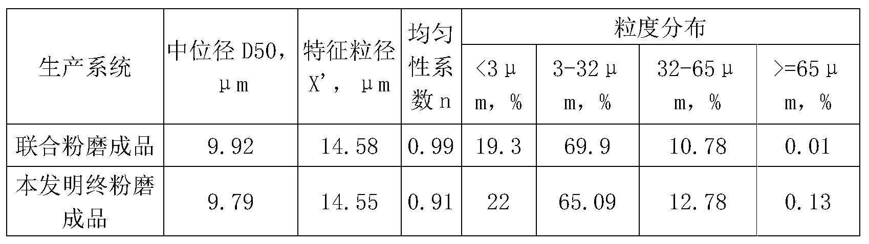
本发明的水泥辊压机终粉磨系统和普通的水泥联合粉磨系统测得的水泥样品数据对比如表1-表2所示:
表1


表2
由表1可以看出,本发明的水泥辊压机终粉磨系统生产的水泥,与水泥联合粉磨系统生产的水泥相比,各项数据相差不大,可以看出质量不相上下;
由表2可以看出,本发明的物料经过静态选粉机11-1和多转子动态选粉机11-2共三次分选后,可以得到粒度分布合理的水泥成品,保证水泥成品良好的工作性能,主要体现在,在中位径和特征粒径基本相同的情况下,辊压机终粉磨水泥均匀性系数n更小,说明辊压机终粉磨水泥成品的粒度分布更宽,粒度分布越宽,水泥的需水量越低,流动度越大,即水泥的工作性能越好。但是本发明较水泥联合粉磨系统在设备数量和成本上大大减少,在相同条件下,每吨水泥系统电耗比带球磨机的联合粉磨系统降低20%以上;因此有利于辊压机终粉磨系统在水泥生产行业中广泛推广。
以上所述仅为本发明的较佳实施例而已,并不用以限制本发明,凡在本发明的精神和原则之内所作的任何修改、等同替换和改进等,均应包含在本发明的保护范围之内。
Claims (10)
- 一种水泥辊压机终粉磨系统,包括辊压机、第一提升机、组合式选粉机、第二提升机、荷重仓、收尘装置和风机;其特征在于:所述组合式选粉机包括设在上方的多转子动态选粉机和设在下方的静态选粉机;所述多转子动态选粉机的下端通过膨胀节与静态选粉机的上端连接;所述静态选粉机包括第一选粉筒体、第一进料口、第一进风口、出料口、第二进料口以及第一出风口;在所述第二进料口与多转子动态选粉机之间设有送料管道,所述送料管道将多转子动态选粉机中分选出的粗粉通过中粗粉出口送回第二进料口;所述第一出风口的上部与多转子动态选粉机的进风管道连通;第一出风口的下端与所述第二进料口连通;所述第一提升机的出料口与所述静态选粉机的第一进料口连接;静态选粉机的出料口与所述第二提升机的进料口连接;第二提升机的出料口与所述荷重仓的进料口连接;荷重仓的出料口与辊压机的进料口连接;所述收尘装置的一端与所述动态选粉机的第二出风口连通;收尘装置的另一端与所述风机连通,风机的出口端与静态选粉机的第一进风口连接。
- 如权利要求1所述的水泥辊压机终粉磨系统,其特征在于:所述多转子动态选粉机包括第二选粉筒体;在第二选粉筒体顶部周向均布有3个以上驱动装置;每个所述驱动装置的下方设有一个转子;所述驱动装置与所述转子通过回转装置连接。
- 如权利要求2所述的水泥辊压机终粉磨系统,其特征在于:在每个所述转子的下方设有选粉漏斗;所述选粉漏斗由圆锥壳体和送料管组成,圆锥壳体的上端大下端小,送料管设于圆锥壳体下端。
- 如权利要求3所述的水泥辊压机终粉磨系统,其特征在于:在所述选粉漏斗下方设有反击锥;在反击锥的下方设有所述进风管道,所述进风管道的下端为第二进风口;所述进风管道与第二选粉筒体之间设有间隙;在第二选粉筒体的下端接近第二进风口处设有所述中粗粉出口;第二选粉筒体上端开有所述第二出风口。
- 如权利要求4所述的水泥辊压机终粉磨系统,其特征在于:还包括储粉壳体,所述储粉壳体上端与所述送料管末端连通,下端通过所述间隙与所述中粗粉出口连通。
- 如权利要求3所述的水泥辊压机终粉磨系统,其特征在于:所述选粉漏斗的上端直径大于转子下端的直径。
- 如权利要求2所述的水泥辊压机终粉磨系统,其特征在于:所述转子的形状为圆锥形,所述转子的锥度区间为0~30°。
- 如权利要求2所述的水泥辊压机终粉磨系统,其特征在于:所述转子的转速区间为15~45m/s。
- 如权利要求2所述的水泥辊压机终粉磨系统,其特征在于:在每个所述转子的周围设有均匀分布的导向叶片;所述导向叶片的间距为10mm~100mm和/或导向叶片的角度为40~80°。
- 一种利用如权利要求1-9任一项所述的水泥辊压机终粉磨系统的工作方法,其特征在于:包括如下步骤:S1、新物料通过第一提升机喂入静态选粉机的第一进料口进行第一次分选;S2、静态选粉机选出的粗粉通过出料口进入第二提升机,第二提升机通过荷重仓将粗粉送入辊压机重新进行辊压粉磨;S3、在风机所产生的负压作用下,静态选粉机选出的细粉通过第一出风口进入多转子动态选粉机的进风通道进行第二次分选;S4、第二次分选后的细粉由收尘装置收集后入成品储存;第二次分选后的粗粉从中粗粉出口进入送料管道、并从第二进料口喂入静态选粉机进行第三次分选;S5、辊压机重新辊压过的物料和新物料通过第一提升机被再次喂入静态选粉机。
Applications Claiming Priority (2)
| Application Number | Priority Date | Filing Date | Title |
|---|---|---|---|
| CN201811043718.3 | 2018-09-07 | ||
| CN201811043718.3A CN109046558B (zh) | 2018-09-07 | 2018-09-07 | 一种水泥辊压机终粉磨系统及工作方法 |
Publications (1)
| Publication Number | Publication Date |
|---|---|
| WO2020048278A1 true WO2020048278A1 (zh) | 2020-03-12 |
Family
ID=64760014
Family Applications (1)
| Application Number | Title | Priority Date | Filing Date |
|---|---|---|---|
| PCT/CN2019/099330 WO2020048278A1 (zh) | 2018-09-07 | 2019-08-06 | 一种水泥辊压机终粉磨系统及工作方法 |
Country Status (2)
| Country | Link |
|---|---|
| CN (1) | CN109046558B (zh) |
| WO (1) | WO2020048278A1 (zh) |
Cited By (1)
| Publication number | Priority date | Publication date | Assignee | Title |
|---|---|---|---|---|
| CN117548186A (zh) * | 2024-01-12 | 2024-02-13 | 潍坊精华装备科技有限公司 | 一种防合格物料回流的高效分选机 |
Families Citing this family (6)
| Publication number | Priority date | Publication date | Assignee | Title |
|---|---|---|---|---|
| CN109046558B (zh) * | 2018-09-07 | 2023-08-25 | 天津水泥工业设计研究院有限公司 | 一种水泥辊压机终粉磨系统及工作方法 |
| CN111569994A (zh) * | 2020-05-25 | 2020-08-25 | 中国中材国际工程股份有限公司 | 生料辊压机终粉磨双风机系统及辊压方法 |
| CN113399032B (zh) * | 2021-06-23 | 2023-01-31 | 中材(天津)粉体技术装备有限公司 | 一种高效梯度联合粉磨系统及粉磨工艺 |
| CN113477525B (zh) * | 2021-07-20 | 2022-06-21 | 天津水泥工业设计研究院有限公司 | 一种带有挡料锥的半成品粗细分离选粉机设计方法 |
| CN113499843A (zh) * | 2021-07-27 | 2021-10-15 | 信诺科技(天津)有限公司 | 一种基于辊压机的水泥终粉磨系统 |
| CN114308335A (zh) * | 2021-12-14 | 2022-04-12 | 湖州霞幕山生态农林发展有限公司 | 一种利用园林废弃物环保处理生活污泥的装置 |
Citations (7)
| Publication number | Priority date | Publication date | Assignee | Title |
|---|---|---|---|---|
| CN201632419U (zh) * | 2010-03-25 | 2010-11-17 | 天津水泥工业设计研究院有限公司 | 一种上、下进料的双分级式高效选粉机 |
| CN203264831U (zh) * | 2013-05-21 | 2013-11-06 | 江苏吉能达建材设备有限公司 | 一种实现半终粉磨工艺的设备 |
| WO2014090711A1 (de) * | 2012-12-13 | 2014-06-19 | Khd Humboldt Wedag Gmbh | Behandlung von mahlgut für die zerkleinerung in einer pressmühle |
| CN205613711U (zh) * | 2016-03-02 | 2016-10-05 | 河南省少林重型机器有限公司 | 多转子立式气流分级机 |
| CN207430482U (zh) * | 2017-11-09 | 2018-06-01 | 成都建筑材料工业设计研究院有限公司 | 一种利用气流颗粒整形的辊压机水泥终粉磨系统 |
| CN108355968A (zh) * | 2018-04-24 | 2018-08-03 | 南京凯盛国际工程有限公司 | 一种干法制砂系统及方法 |
| CN109046558A (zh) * | 2018-09-07 | 2018-12-21 | 天津水泥工业设计研究院有限公司 | 一种水泥辊压机终粉磨系统及工作方法 |
Family Cites Families (7)
| Publication number | Priority date | Publication date | Assignee | Title |
|---|---|---|---|---|
| CN2326355Y (zh) * | 1998-01-11 | 1999-06-30 | 周国才 | 双转子选粉机 |
| CN2756331Y (zh) * | 2004-09-07 | 2006-02-08 | 何亚民 | V形叶栅选粉机 |
| CN202270652U (zh) * | 2011-09-29 | 2012-06-13 | 中材淄博重型机械有限公司 | 用于粉状物料分级的选粉机 |
| CN103041904A (zh) * | 2012-12-25 | 2013-04-17 | 鞍山钢铁集团公司 | 一种用辊压机生产钢渣粉的方法 |
| CN103230826B (zh) * | 2013-05-21 | 2017-06-20 | 江苏吉能达环境能源科技有限公司 | 半终粉磨工艺及其设备 |
| CN107790266A (zh) * | 2017-11-09 | 2018-03-13 | 成都建筑材料工业设计研究院有限公司 | 一种利用气流颗粒整形的辊压机水泥终粉磨系统 |
| CN209061201U (zh) * | 2018-09-07 | 2019-07-05 | 天津水泥工业设计研究院有限公司 | 一种水泥辊压机终粉磨系统 |
-
2018
- 2018-09-07 CN CN201811043718.3A patent/CN109046558B/zh active Active
-
2019
- 2019-08-06 WO PCT/CN2019/099330 patent/WO2020048278A1/zh active Application Filing
Patent Citations (7)
| Publication number | Priority date | Publication date | Assignee | Title |
|---|---|---|---|---|
| CN201632419U (zh) * | 2010-03-25 | 2010-11-17 | 天津水泥工业设计研究院有限公司 | 一种上、下进料的双分级式高效选粉机 |
| WO2014090711A1 (de) * | 2012-12-13 | 2014-06-19 | Khd Humboldt Wedag Gmbh | Behandlung von mahlgut für die zerkleinerung in einer pressmühle |
| CN203264831U (zh) * | 2013-05-21 | 2013-11-06 | 江苏吉能达建材设备有限公司 | 一种实现半终粉磨工艺的设备 |
| CN205613711U (zh) * | 2016-03-02 | 2016-10-05 | 河南省少林重型机器有限公司 | 多转子立式气流分级机 |
| CN207430482U (zh) * | 2017-11-09 | 2018-06-01 | 成都建筑材料工业设计研究院有限公司 | 一种利用气流颗粒整形的辊压机水泥终粉磨系统 |
| CN108355968A (zh) * | 2018-04-24 | 2018-08-03 | 南京凯盛国际工程有限公司 | 一种干法制砂系统及方法 |
| CN109046558A (zh) * | 2018-09-07 | 2018-12-21 | 天津水泥工业设计研究院有限公司 | 一种水泥辊压机终粉磨系统及工作方法 |
Cited By (2)
| Publication number | Priority date | Publication date | Assignee | Title |
|---|---|---|---|---|
| CN117548186A (zh) * | 2024-01-12 | 2024-02-13 | 潍坊精华装备科技有限公司 | 一种防合格物料回流的高效分选机 |
| CN117548186B (zh) * | 2024-01-12 | 2024-04-05 | 潍坊精华装备科技有限公司 | 一种防合格物料回流的高效分选机 |
Also Published As
| Publication number | Publication date |
|---|---|
| CN109046558B (zh) | 2023-08-25 |
| CN109046558A (zh) | 2018-12-21 |
Similar Documents
| Publication | Publication Date | Title |
|---|---|---|
| WO2020048278A1 (zh) | 一种水泥辊压机终粉磨系统及工作方法 | |
| WO2021093255A1 (zh) | 一种外循环辊式立磨 | |
| CN107350062A (zh) | 一种采用非金属研磨介质的选粉机外置式立磨联合粉磨系统 | |
| CN111495560A (zh) | 一种静态双分级选粉机及半终预粉磨系统 | |
| CN111822129A (zh) | 一种铁矿石干法磨矿选矿装置及工艺 | |
| WO2020048279A1 (zh) | 一种多转子动态选粉机、选粉方法及辊压机终粉磨系统 | |
| CN113680662A (zh) | 用于工业废渣超细加工再循环利用的装置 | |
| CN110711639B (zh) | 一种人工砂制造工艺及装置 | |
| CN201102015Y (zh) | 泻落式选粉机 | |
| CN207770008U (zh) | 一种粉磨设备 | |
| CN207507611U (zh) | 一种采用非金属研磨介质的选粉机外置式立磨联合粉磨系统 | |
| CN113369140B (zh) | 一种基于半成品粗细分离的超细选粉机设计方法 | |
| CN213557749U (zh) | 生产多组分机制砂的精细选粉机 | |
| WO2020037832A1 (zh) | 一种超细粉体分选机 | |
| CN210304024U (zh) | 一种三循环闭路粉磨系统 | |
| CN209061201U (zh) | 一种水泥辊压机终粉磨系统 | |
| CN109569853B (zh) | 一种球磨机和辊压机组成的联合粉磨系统 | |
| CN106466653B (zh) | 新型立磨装置 | |
| CN200939434Y (zh) | 可调强制涡流粉煤灰分选机 | |
| CN209577389U (zh) | 粉状原料分选机 | |
| CN207823148U (zh) | 一种铝粉分选系统用打散机 | |
| CN209093894U (zh) | 高效选粉机 | |
| CN208928578U (zh) | 一种多级打散静电中和选粉装置 | |
| CN207547025U (zh) | 一种卧式高速精密多头分级机 | |
| CN111940294A (zh) | 一种砂石级配系统 |
Legal Events
| Date | Code | Title | Description |
|---|---|---|---|
| 121 | Ep: the epo has been informed by wipo that ep was designated in this application |
Ref document number: 19857589 Country of ref document: EP Kind code of ref document: A1 |
|
| NENP | Non-entry into the national phase |
Ref country code: DE |
|
| 122 | Ep: pct application non-entry in european phase |
Ref document number: 19857589 Country of ref document: EP Kind code of ref document: A1 |