WO2020045313A1 - マスク推定装置、マスク推定方法及びマスク推定プログラム - Google Patents
マスク推定装置、マスク推定方法及びマスク推定プログラム Download PDFInfo
- Publication number
- WO2020045313A1 WO2020045313A1 PCT/JP2019/033184 JP2019033184W WO2020045313A1 WO 2020045313 A1 WO2020045313 A1 WO 2020045313A1 JP 2019033184 W JP2019033184 W JP 2019033184W WO 2020045313 A1 WO2020045313 A1 WO 2020045313A1
- Authority
- WO
- WIPO (PCT)
- Prior art keywords
- mask
- estimating
- target
- signal
- unit
- Prior art date
- Legal status (The legal status is an assumption and is not a legal conclusion. Google has not performed a legal analysis and makes no representation as to the accuracy of the status listed.)
- Ceased
Links
Images




Classifications
-
- G—PHYSICS
- G10—MUSICAL INSTRUMENTS; ACOUSTICS
- G10L—SPEECH ANALYSIS TECHNIQUES OR SPEECH SYNTHESIS; SPEECH RECOGNITION; SPEECH OR VOICE PROCESSING TECHNIQUES; SPEECH OR AUDIO CODING OR DECODING
- G10L21/00—Speech or voice signal processing techniques to produce another audible or non-audible signal, e.g. visual or tactile, in order to modify its quality or its intelligibility
- G10L21/02—Speech enhancement, e.g. noise reduction or echo cancellation
- G10L21/0208—Noise filtering
- G10L21/0216—Noise filtering characterised by the method used for estimating noise
- G10L21/0232—Processing in the frequency domain
-
- G—PHYSICS
- G06—COMPUTING OR CALCULATING; COUNTING
- G06F—ELECTRIC DIGITAL DATA PROCESSING
- G06F30/00—Computer-aided design [CAD]
- G06F30/20—Design optimisation, verification or simulation
- G06F30/27—Design optimisation, verification or simulation using machine learning, e.g. artificial intelligence, neural networks, support vector machines [SVM] or training a model
-
- G—PHYSICS
- G06—COMPUTING OR CALCULATING; COUNTING
- G06N—COMPUTING ARRANGEMENTS BASED ON SPECIFIC COMPUTATIONAL MODELS
- G06N3/00—Computing arrangements based on biological models
- G06N3/02—Neural networks
- G06N3/04—Architecture, e.g. interconnection topology
- G06N3/044—Recurrent networks, e.g. Hopfield networks
-
- G—PHYSICS
- G06—COMPUTING OR CALCULATING; COUNTING
- G06N—COMPUTING ARRANGEMENTS BASED ON SPECIFIC COMPUTATIONAL MODELS
- G06N3/00—Computing arrangements based on biological models
- G06N3/02—Neural networks
- G06N3/04—Architecture, e.g. interconnection topology
- G06N3/044—Recurrent networks, e.g. Hopfield networks
- G06N3/0442—Recurrent networks, e.g. Hopfield networks characterised by memory or gating, e.g. long short-term memory [LSTM] or gated recurrent units [GRU]
-
- G—PHYSICS
- G06—COMPUTING OR CALCULATING; COUNTING
- G06N—COMPUTING ARRANGEMENTS BASED ON SPECIFIC COMPUTATIONAL MODELS
- G06N3/00—Computing arrangements based on biological models
- G06N3/02—Neural networks
- G06N3/08—Learning methods
-
- G—PHYSICS
- G06—COMPUTING OR CALCULATING; COUNTING
- G06N—COMPUTING ARRANGEMENTS BASED ON SPECIFIC COMPUTATIONAL MODELS
- G06N3/00—Computing arrangements based on biological models
- G06N3/02—Neural networks
- G06N3/08—Learning methods
- G06N3/09—Supervised learning
-
- G—PHYSICS
- G10—MUSICAL INSTRUMENTS; ACOUSTICS
- G10L—SPEECH ANALYSIS TECHNIQUES OR SPEECH SYNTHESIS; SPEECH RECOGNITION; SPEECH OR VOICE PROCESSING TECHNIQUES; SPEECH OR AUDIO CODING OR DECODING
- G10L15/00—Speech recognition
- G10L15/28—Constructional details of speech recognition systems
-
- G—PHYSICS
- G10—MUSICAL INSTRUMENTS; ACOUSTICS
- G10L—SPEECH ANALYSIS TECHNIQUES OR SPEECH SYNTHESIS; SPEECH RECOGNITION; SPEECH OR VOICE PROCESSING TECHNIQUES; SPEECH OR AUDIO CODING OR DECODING
- G10L25/00—Speech or voice analysis techniques not restricted to a single one of groups G10L15/00 - G10L21/00
- G10L25/27—Speech or voice analysis techniques not restricted to a single one of groups G10L15/00 - G10L21/00 characterised by the analysis technique
- G10L25/30—Speech or voice analysis techniques not restricted to a single one of groups G10L15/00 - G10L21/00 characterised by the analysis technique using neural networks
-
- G—PHYSICS
- G10—MUSICAL INSTRUMENTS; ACOUSTICS
- G10L—SPEECH ANALYSIS TECHNIQUES OR SPEECH SYNTHESIS; SPEECH RECOGNITION; SPEECH OR VOICE PROCESSING TECHNIQUES; SPEECH OR AUDIO CODING OR DECODING
- G10L25/00—Speech or voice analysis techniques not restricted to a single one of groups G10L15/00 - G10L21/00
- G10L25/48—Speech or voice analysis techniques not restricted to a single one of groups G10L15/00 - G10L21/00 specially adapted for particular use
- G10L25/51—Speech or voice analysis techniques not restricted to a single one of groups G10L15/00 - G10L21/00 specially adapted for particular use for comparison or discrimination
-
- G—PHYSICS
- G06—COMPUTING OR CALCULATING; COUNTING
- G06N—COMPUTING ARRANGEMENTS BASED ON SPECIFIC COMPUTATIONAL MODELS
- G06N7/00—Computing arrangements based on specific mathematical models
- G06N7/01—Probabilistic graphical models, e.g. probabilistic networks
-
- G—PHYSICS
- G10—MUSICAL INSTRUMENTS; ACOUSTICS
- G10L—SPEECH ANALYSIS TECHNIQUES OR SPEECH SYNTHESIS; SPEECH RECOGNITION; SPEECH OR VOICE PROCESSING TECHNIQUES; SPEECH OR AUDIO CODING OR DECODING
- G10L21/00—Speech or voice signal processing techniques to produce another audible or non-audible signal, e.g. visual or tactile, in order to modify its quality or its intelligibility
- G10L21/02—Speech enhancement, e.g. noise reduction or echo cancellation
- G10L21/0208—Noise filtering
- G10L21/0216—Noise filtering characterised by the method used for estimating noise
- G10L2021/02161—Number of inputs available containing the signal or the noise to be suppressed
- G10L2021/02166—Microphone arrays; Beamforming
-
- G—PHYSICS
- G10—MUSICAL INSTRUMENTS; ACOUSTICS
- G10L—SPEECH ANALYSIS TECHNIQUES OR SPEECH SYNTHESIS; SPEECH RECOGNITION; SPEECH OR VOICE PROCESSING TECHNIQUES; SPEECH OR AUDIO CODING OR DECODING
- G10L21/00—Speech or voice signal processing techniques to produce another audible or non-audible signal, e.g. visual or tactile, in order to modify its quality or its intelligibility
- G10L21/02—Speech enhancement, e.g. noise reduction or echo cancellation
- G10L21/0208—Noise filtering
- G10L21/0216—Noise filtering characterised by the method used for estimating noise
Definitions
- the present invention relates to a mask estimation device, a mask estimation method, and a mask estimation program.
- the estimated mask is used for beamforming or the like for removing noise in automatic speech recognition (ASR: automatic speech recognition).
- ASR automatic speech recognition
- Non-Patent Document 1 discloses a technique for combining a method of estimating a mask using a neural network and a method of estimating a mask by spatial clustering in order to accurately estimate a mask from observation signals recorded by a plurality of microphones. It has been disclosed.
- Non-Patent Document 1 is to read all observation signals and then estimate a mask by batch processing.
- an on-line type technology for sequentially estimating a mask according to an environment that changes every moment may be required.
- the technique disclosed in Non-Patent Document 1 cannot perform online mask estimation. As described above, the conventional technique has a problem that the mask estimation cannot be accurately performed online.
- the mask estimating apparatus obtains a segment to be processed as a target segment among segments of continuous time from an observation signal of the target segment recorded at a plurality of positions.
- a first mask estimating unit for estimating a first mask which is an occupancy of a target signal with respect to an observation signal of the target segment based on a first feature amount obtained, and an estimation result of the first mask in the target segment And a second feature value obtained from the observation signal of the target segment, a second mask that is a parameter for modeling the second feature value and an occupancy of the target signal with respect to the observation signal.
- a second mask estimator for estimating.
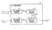
- FIG. 1 is a diagram illustrating an example of a configuration of the mask estimation device according to the first embodiment.
- FIG. 2 is a diagram illustrating an example of a configuration of a second mask estimating unit according to the first embodiment.
- FIG. 3 is a flowchart illustrating a flow of a process of the mask estimation device according to the first embodiment.
- FIG. 4 is a flowchart illustrating the flow of the process of the mask estimation device according to the first embodiment.
- FIG. 5 is a diagram illustrating an example of a configuration of a mask estimation device according to the second embodiment.
- FIG. 6 is a flowchart illustrating the flow of the process of the mask estimation device according to the second embodiment.
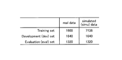
- FIG. 7 is a diagram showing audio data used in the experiment.
- FIG. 1 is a diagram illustrating an example of a configuration of the mask estimation device according to the first embodiment.
- FIG. 2 is a diagram illustrating an example of a configuration of a second mask estimating unit according to the first embodiment.
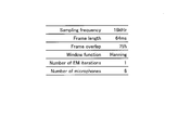
- FIG. 8 is a diagram showing hyperparameters in the experiment.
- FIG. 9 is a diagram showing the results of the experiment.
- FIG. 10 is a diagram showing the results of the experiment.
- FIG. 11 is a diagram illustrating an example of a computer that executes a mask estimation program.
- the mask estimation device is input with observation signals recorded at a plurality of positions in a target segment among segments of continuous time, or feature amounts extracted from the observation signals.
- the observation signal includes both the target sound and the background noise generated from the target sound source.
- the observation signals are recorded by microphones installed at a plurality of different positions.
- the mask estimation device 10 can estimate a mask for extracting a target signal from an observation signal.
- the mask is the probability that the target signal occupies the observation signal at each time frequency point. That is, the mask is the occupancy of the signal of the target voice with respect to the observation signal at each time frequency point.
- the mask estimation device 10 can estimate a mask for extracting noise from an observation signal.
- the mask is the probability that the noise signal occupies the observed signal at each time frequency point. That is, the mask is the occupancy of the noise signal with respect to the observation signal at each time frequency point.
- the signal of the target voice is called a target signal
- the signal of a sound other than the target voice is called a noise signal.
- the target voice is a voice uttered by a specific speaker.
- FIG. 1 is a diagram illustrating an example of a configuration of the mask estimation device according to the first embodiment.
- the mask estimation device 10 includes a first feature amount extraction unit 11, a first mask estimation unit 12, a second feature amount extraction unit 13, and a second mask estimation unit 14.
- the mask estimating apparatus 10 receives an input of an observation signal in mini-batch units.
- the mini-batch is a unit of a predetermined time segment. For example, 0 ms to 500 ms can be set as the first mini-batch from the start of the observation signal recording, 500 ms to 750 ms can be set as the second mini-batch, and the mini-batch can be set every 250 ms thereafter. Also, the length of each mini-batch may be constant or different. Later, B l denote the l-th mini-batch. That is, a partial section obtained by dividing the entire observation signal at predetermined time intervals is called a mini-batch.
- the mask estimation device 10 converts the observation signal input in the unit of mini-batch into a frequency domain signal for each short-time frame based on short-time frequency analysis.
- the observation signal after this conversion may be input to the mask estimation device 10.
- STFT short-time Fourier transform
- yn , f, and m represent the STFT of the observation signal.
- n and f are time and frequency indices, respectively.
- m is an index representing a microphone that has recorded the observation signal. Further, it is assumed that 1 ⁇ n ⁇ N t , 0 ⁇ f ⁇ N f , and 1 ⁇ m ⁇ N m are satisfied.
- the first mask estimating unit 12 estimates the first mask based on the spectral feature obtained from the observation signal of the target segment recorded at one or more positions.
- the target segment is a mini-batch corresponding to the observation signal input to the mask estimation device 10.
- the spectral feature is an example of a first feature.
- the first mask estimating unit 12 estimates a first mask using a neural network.
- the first mask estimating unit 12 inputs the spectral feature amount Y n, m extracted by the first feature amount extracting unit 11 to the neural network, and outputs only the observation signal recorded by the m-th microphone as the output of the neural network.
- a mask Mn , fd, DNN To obtain a mask Mn , fd, DNN .
- the first mask estimating unit 12 estimates a mask based on observation signals recorded by each of the plurality of microphones, obtains a plurality of estimated values of the masks, and integrates the estimated values of the plurality of masks into one. It can also be an estimated value of the mask.
- a method of integrating masks there is a method of taking an average value between estimated values, taking a median value (median), and the like.
- the first mask estimating unit 12 is based on the first feature value obtained from the observation signal of the target segment recorded at a plurality of positions, and is the first occupancy of the target signal with respect to the observation signal of the target segment.
- the mask may be estimated, and the first mask may be calculated by using a part of the observation signal of the target segment (for example, the observation signal of the m-th microphone) or the entire observation signal (M observation signals). (Observation signal about a microphone) may be used.
- the first mask estimating unit 12 uses a neural network capable of processing the sequentially input spectral features on-line.
- the first mask estimation unit 12 uses an LSTM (long @ short-term @ memory) network.
- LSTM long @ short-term @ memory
- the parameters of the neural network have been learned using a simulation voice including both the target voice and noise.
- the first mask estimation unit 12, M n, f 0, DNN, and M n can be obtained two types of masks f 1, DNN.
- M n, f 0, DNN is a mask for extracting a noise signal from the observed signal at the time frequency point (n, f).
- Mn, f1 , DNN is a mask for extracting the target signal from the observation signal at the time frequency point (n, f).
- Mn, fd, and DNN are numerical values ranging from 0 to 1.
- the first mask estimating unit 12 outputs one of the masks from the neural network, and the other mask outputs the other mask. , Can be calculated by subtracting the output mask from 1. Therefore, the first mask estimation unit 12, M n from the neural network, f 0, DNN and M n, may be configured to output both f 1, DNN, so as to output either one Is also good.
- the second feature quantity extraction unit 13 the vector y n, from f, as shown in equation (4), and extracts a spatial feature quantity X n, f.
- the second feature extraction unit 13 extracts the spatial feature Xn, f from the observation signal of the target segment.
- the elements of the vector yn , f are the STFTs of the observation signal for each microphone.
- represents the Euclidean norm.
- T represents non-conjugate transposition.
- the second mask estimating unit 14 calculates a spatial parameter for modeling the spatial feature of the target segment based on the estimation result of the first mask in the target segment and a spatial feature obtained from an observation signal of the target segment.
- the second mask which is the degree of occupancy of the target signal with respect to the observation signal, is estimated.
- the space feature is an example of a second feature.
- the second mask estimating unit 14 estimates the second mask for each target segment based on the distribution model of the spatial feature amount and the first mask when the spatial parameter is a condition.
- the second mask estimating unit 14 uses a complex angular Gaussian mixture model (cACGMM: complex ⁇ angular ⁇ central ⁇ Gaussian ⁇ mixture ⁇ model) as a distribution model of the spatial feature.
- cACGMM is defined as in equation (5).
- parameter set theta SC is, ⁇ w d f ⁇ , ⁇ R d f ⁇ is expressed as.
- w d f it is a mixture weight, is the prior probability of d n, f.
- the w d f is equivalent to the first mask, it assumed to be replaced by its estimated value.
- Equation (5) represents a conditional distribution of a spatial feature X defined by a complex angular central Gaussian (cACG) distribution when d is given.
- cACG complex angular central Gaussian
- the spatial parameters R d f are parameters defining the shape of the complex angular Gaussian distribution is positive definite Hermitian matrix of N m ⁇ N m-dimensional.
- det represents a determinant.
- H represents conjugate transposition.
- the second mask estimating unit 14 estimates the second mask by an EM (expectation-maximization) algorithm using the complex angle Gaussian mixture model described above.
- FIG. 2 is a diagram illustrating an example of a configuration of a second mask estimating unit according to the first embodiment. As illustrated in FIG. 2, the second mask estimating unit 14 includes a setting unit 141, a first updating unit 142, a second updating unit 143, a determining unit 144, and a storage unit 145. Although the storage unit 145 is provided in the second mask estimation unit 14 in FIG. 2, the storage unit 145 may be provided outside the second mask estimation unit 14, that is, as a storage unit in the mask estimation device 10. It goes without saying that it is good.
- the setting unit 141 sets the first mask estimated for the target segment and the spatial parameter in the immediately preceding segment, respectively, as the initial values of the second mask and the spatial parameter in the target segment. Specifically, the setting unit 141 sets the initial values of the second masks Mn, fd, and INT as in Expression (6).
- the second mask estimating unit 14 acquires the first masks Mn , fd , and DNN from the first mask estimating unit 12. Further, when the mini-batch corresponding to the target segment and B l, setting unit 141 sets an initial value of the spatial parameter R f, l d as (7). In addition, the setting unit 141 sets the cumulative sum f f, l ⁇ 1 d of the first mask as shown in Expression (8).
- the first updating unit 142 updates a spatial parameter based on the cumulative sum of the first mask up to the target segment, the spatial feature amount of the target segment, and the second mask. Specifically, the first updating unit 142 updates the spatial parameter R f, l d as (9). At this time, the first updating unit 142 calculates the update space parameter R f, new d as shown in Expression (10).
- the second updating unit 143 updates the second mask based on the spatial feature of the target segment, the first mask, and the spatial parameter. Specifically, the second updating unit 143 updates the second mask Mn, fd, INT as in Expression (11).
- the determining unit 144 determines whether a predetermined convergence condition is satisfied, and determines that the convergence condition is not satisfied.
- the update unit 142 and the second update unit 143 further execute the processing. That is, the first updating unit 142 and the second updating unit 143 repeat the processing until the predetermined convergence condition is satisfied.
- the second mask and the spatial parameters are updated each time the repetition is performed, and the accuracy of extracting the target voice of the second mask is improved.
- the convergence condition of the determination unit 144 may be that the number of repetitions exceeds a threshold.
- the threshold for the number of repetitions can be set to one. That is, the first update unit 142 and the second update unit 143 may perform the update process only once for each mini-batch.
- the condition for the determination unit 144 to determine the convergence may be that the update amount of the second mask or the update amount of the spatial parameter in one update is equal to or less than a certain value.
- the determination unit 144 may determine that the convergence has occurred when the update amount of the value of the likelihood function L ( ⁇ SC ) represented by Expression (12) becomes equal to or less than a certain value.
- X l is a set of mini-batch B spatial feature observed until l amount X n, f.
- Y l is a set of spatial parameters Y n, m observed up to the mini-batch B 1 .
- ⁇ DNN is a neural network parameter of the first mask estimating unit 12.
- Expression (12) is rewritten as expression (13).
- (13) of the right side of the equation p (d n, f d
- the second mask estimating unit 14 maximizes the likelihood function L ( ⁇ SC ) for each mini-batch in the same manner as the method described in Non-Patent Document 1, and the second mask M n, f An estimate of d, INT and the parameter ⁇ SC can be made.
- the storage unit stores the spatial parameters estimated in each mini-batch, and uses the spatial parameters as initial values of the spatial parameters in the next mini-batch, thereby updating the likelihood function separately for each mini-batch. Also, the mask estimation can be performed with high accuracy.
- the storage unit 145 stores a value calculated in the previous segment and used in the initial setting of the target segment. That is, the storage unit 145 stores the mini-batch B spatial parameters calculated in l-1 R f, l- 1 d and cumulative sum lambda f, l-1 d of the first mask.
- the setting unit 141 may set a value learned using predetermined learning data as the initial value R f, 0 d of the spatial parameter.
- the learning data of the spatial parameters R f, 0 1 the target signal is the observation signal obtained when the specified speaker utters with noise-free environment.
- the setting unit 141 may set the unit matrix to the initial value R f, 0 1 spatial parameters.
- the spatial parameter R f, 0 0 of the noise signal may be estimated from the observed signal in which only noise is included.
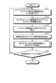
- FIG. 3 is a flowchart illustrating a flow of a process of the mask estimation device according to the first embodiment.
- the mask estimating apparatus 10 receives an input of observation signals in units of mini-batch (step S11).
- the mask estimation device 10 may calculate the STFT of the observation signal.
- the observation signal input to the mask estimating apparatus 10 may be a signal subjected to STFT.
- the mask estimation device 10 extracts a spectral feature from the STFT of the observation signal for each microphone (step S12). Then, the mask estimating apparatus 10 estimates the first mask from the spectral feature (Step S13). At this time, the mask estimating apparatus 10 can estimate the first mask using a neural network.
- the mask estimating apparatus 10 extracts a spatial feature amount from the STFT of the observation signal (step S14). Then, the mask estimating apparatus 10 estimates the second mask from the first mask and the spatial feature (Step S15).
- the mask estimation device 10 determines whether or not there is an unprocessed mini-batch (step S16). If there is an unprocessed mini-batch (Step S16, Yes), the mask estimation device 10 returns to Step S11 and accepts the input of the observation signal of the next mini-batch. On the other hand, when there is no unprocessed mini-batch (Step S16, No), the mask estimation device 10 ends the process.
- FIG. 4 is a flowchart illustrating the flow of the process of the mask estimation device according to the first embodiment.
- the mask estimating apparatus 10 sets the initial values of the second mask, the spatial parameters, and the cumulative sum of the first mask (step S151).
- the mask estimation device 10 updates the spatial parameter using the cumulative sum of the first mask, the spatial feature, and the second mask (step S152).
- the mask estimating apparatus 10 updates the second mask based on the spatial feature value, the first mask, and the spatial parameter (Step S153).
- the mask estimating apparatus 10 determines whether or not the second mask has converged (step S154). When determining that the second mask has not converged (No at Step S154), the mask estimation device 10 returns to Step S152 and further updates the spatial parameters. On the other hand, when the mask estimation device 10 determines that the second mask has converged (step S154, Yes), the mask estimation device 10 ends the processing.
- the first mask estimating unit 12 sets the first segment obtained from observation signals of the target segments recorded at a plurality of positions, with the segment to be processed among the segments of the continuous time as the target segment.
- a first mask which is the degree of occupancy of the target signal with respect to the observation signal of the target segment, is estimated based on the feature amount of.
- the second mask estimating unit 14 models the second feature based on the estimation result of the first mask in the target segment and the second feature obtained from the observation signal of the target segment.
- a second mask which is the parameter and the degree of occupation of the target signal with respect to the observed signal, is estimated.
- the mask estimation device 10 can accurately estimate the final mask by combining the two mask estimation methods. Further, the mask estimating apparatus 10 can sequentially estimate a mask for an observation signal for each target segment. For this reason, according to the first embodiment, it is possible to accurately perform mask estimation online.
- the mask estimating apparatus 10 combines a method using a neural network for inputting a spectral feature and a method using a distribution model. For this reason, for example, even when there is a mismatch between the parameters of the pre-trained neural network and the observation signal, the accuracy of the mask can be improved by using the spatial parameters. Further, even when there is a frequency band having a particularly bad signal-to-noise ratio, highly accurate mask estimation becomes possible by considering the frequency pattern of the target signal based on the spectral feature.
- the mask estimating apparatus 10 substitutes the estimated value of the first mask as the estimated value of the second mask from the first mini-batch to a predetermined mini-batch, and in subsequent mini-batches, The second mask is estimated using the calculated value.
- the mask estimating apparatus 10 replaces the first mask with the second mask until the spatial parameter is calculated using the observation signal including a sufficient amount of the target signal. After the spatial parameter is calculated using the observation signal including a sufficient amount of the target signal, the second mask is estimated using the calculated value (estimated value) of the spatial parameter.
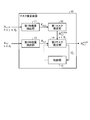
- the mask estimation device 10 further includes a control unit 15 in addition to the same processing units as in the first embodiment.
- FIG. 5 is a diagram illustrating an example of a configuration of a mask estimation device according to the second embodiment.
- the control unit 15 determines whether or not the amount of the target signal included in the observation signal up to the target segment, which is the segment for which the mask is to be estimated, exceeds a predetermined threshold.
- the control unit 15 causes the second mask estimating unit 14 to perform the second mask estimation using the calculated value of the spatial parameter, as in the first embodiment. Control is performed to estimate the mask.
- the control unit 15 controls the second mask estimation unit 14 to substitute the estimated value of the first mask with the estimated value of the second mask. . Accordingly, in the second embodiment, the mask estimation device 10 can accurately estimate the second mask even when a proper initial value is not given to the spatial parameter.
- the control unit 15 determines whether or not the amount of the target signal included in the observation signal of the past segment including the target segment exceeds the threshold based on the predetermined estimated value. For example, the control unit 15 determines whether or not the cumulative sum ⁇ f, l 1 of the first mask for the target signal exceeds a threshold.
- lambda f, l 1 is larger as the number of frames containing the desired signal.
- control unit 15 may make the determination based on the number of processed mini-batches.
- control unit 15 may make the determination using the length of the voice section detected based on the voice section detection that determines whether or not voice is included in the observation signal.
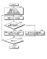
- FIG. 6 is a flowchart illustrating the flow of the process of the mask estimation device according to the second embodiment.
- the process in FIG. 6 corresponds to step S15 in FIG. 3, similarly to the process in FIG.
- the processing in FIG. 6 targets the observation signals in mini-batch units input in step S11 in FIG.
- the mask estimating apparatus 10 sets initial values of the second mask, the spatial parameters, and the cumulative sum of the first mask in each mini-batch (step S251).
- the mask estimating apparatus 10 updates the spatial parameter using the cumulative sum of the first mask, the spatial feature, and the second mask (step S252).
- the mask estimating apparatus 10 determines whether or not the cumulative sum of the first mask is equal to or greater than a threshold (step S253).
- the mask estimation device 10 updates the second mask using the spatial parameter updated at Step S252 (Step S254).
- the mask estimation device 10 uses the estimated value of the first mask as a substitute for the estimated value of the second mask (Step S255). .
- the mask estimating apparatus 10 determines whether or not the update of the spatial parameter has converged (step S256).
- step S256 determines that the update of the spatial parameter has not converged (step S256, No)
- the process returns to step S252, and further updates the spatial parameter.
- step S256, Yes determines that the update of the spatial parameter has converged (step S256, Yes)
- the mask estimation device 10 ends the processing.
- the mask estimation device 10 updates the spatial parameter at Step S252. Even when the cumulative value of the first mask is equal to or smaller than the threshold value, the spatial parameter for the target signal is updated, so that when the cumulative sum of the first mask exceeds the threshold value, the spatial parameter for the target signal is estimated. This is because accuracy can be increased.
- the voice data is obtained by recording a voice reading a newspaper under a plurality of noise environments by a tablet terminal having a plurality of microphones.
- the audio data includes a plurality of subsets. Each subset includes data (real data) actually recorded and data (simu data) generated by simulation.
- FIG. 7 shows the number of utterances of each data.
- FIG. 7 is a diagram showing audio data used in the experiment.
- the mask was estimated by a plurality of methods including the conventional method and the method of the embodiment, and the target speech was extracted using the estimated mask, and then speech recognition was performed.
- Conventional techniques are a mask estimation technique by DNN (LSTM) and a mask estimation technique by spatial clustering (cACGMM).
- the initial values of the spatial parameters are those that have been learned in advance.
- the length of the first mini-batch was set to 500 ms, and the length of the second and subsequent mini-batches was set to 250 ms.
- the setting of each of the other hyperparameters is as shown in FIG.
- FIG. 8 is a diagram showing hyperparameters in the experiment.
- the value of Number of EM iterations is 1. This indicates that for each mini-batch, when the mask estimating apparatus 10 estimates the second mask, the spatial parameter and the second mask are updated only once.
- FIG. 9 shows the WER (Word error rate) when speech recognition is performed by estimating a mask by each method.
- FIG. 9 is a diagram showing the results of the experiment. As shown in FIG. 9, the word error rate when the mask was estimated by the method (Proposed) of the embodiment was generally lower than that of the conventional method. From this, it can be said that the mask estimation method of the embodiment has an effect of improving the accuracy of speech recognition as compared with the conventional method.
- FIG. 10 shows the result of a similar experiment conducted by changing the setting method of the spatial parameter when estimating the second mask.
- FIG. 10 is a diagram showing the results of the experiment.
- Bus, Caf, Ped, and Str represent the plurality of noise environments described above.
- NoNoPrior in FIG. 10 is a method of setting a unit matrix to an initial value of a spatial parameter in the first embodiment.
- PostTrained is a method according to the second embodiment, that is, a method in which the control unit 15 controls whether to substitute the estimated value of the first mask for the estimated value of the second mask.
- the control unit 15 performs the determination using the cumulative sum of the first mask, and the threshold is set to 1.5.
- the word error rates of NoPrior and PostTrained were lower than those of the conventional method.
- NoPrior and PostTrained are methods that do not require prior learning of spatial parameters. From this, it can be said that the mask estimation method of the embodiment can improve the accuracy of speech recognition as compared with the conventional method without performing prior learning.
- each component of each device illustrated is a functional concept and does not necessarily need to be physically configured as illustrated. That is, the specific form of distribution and integration of each device is not limited to the illustrated one, and all or a part thereof may be functionally or physically distributed or physically divided into arbitrary units according to various loads and usage conditions. Can be integrated and configured. Further, all or any part of each processing function performed by each device is realized by a CPU (Central Processing Unit) and a program analyzed and executed by the CPU, or hardware by wired logic is used. It can be realized as
- CPU Central Processing Unit
- the mask estimating apparatus 10 can be implemented by installing a mask estimating program for executing the mask estimating process as package software or online software on a desired computer.
- the information processing apparatus can function as the mask estimation apparatus 10.
- the information processing apparatus referred to here includes a desktop or notebook personal computer.
- the information processing apparatus includes mobile communication terminals such as a smartphone, a mobile phone, and a PHS (Personal Handyphone System), and a slate terminal such as a PDA (Personal Digital Assistant).
- the mask estimation device 10 can also be implemented as a learning server device that provides the client with a terminal device used by a user and provides the client with a service related to the above-described mask estimation process.
- the mask estimation server device is implemented as a server device that provides a mask estimation service in which an observation signal is input and a second mask is output.
- the mask estimation server device may be implemented as a Web server, or may be implemented as a cloud that provides services related to the above-described mask estimation process by outsourcing.
- FIG. 11 is a diagram illustrating an example of a computer that executes a mask estimation program.
- the computer 1000 has, for example, a memory 1010 and a CPU 1020.
- the computer 1000 has a hard disk drive interface 1030, a disk drive interface 1040, a serial port interface 1050, a video adapter 1060, and a network interface 1070. These components are connected by a bus 1080.
- the memory 1010 includes a ROM (Read Only Memory) 1011 and a RAM (Random Access Memory) 1012.
- the ROM 1011 stores, for example, a boot program such as a BIOS (Basic Input Output System).
- BIOS Basic Input Output System
- the hard disk drive interface 1030 is connected to the hard disk drive 1090.
- the disk drive interface 1040 is connected to the disk drive 1100.
- a removable storage medium such as a magnetic disk or an optical disk is inserted into the disk drive 1100.
- the serial port interface 1050 is connected to, for example, a mouse 1110 and a keyboard 1120.
- the video adapter 1060 is connected to the display 1130, for example.
- the hard disk drive 1090 stores, for example, the OS 1091, the application program 1092, the program module 1093, and the program data 1094. That is, a program that defines each process of the mask estimation device 10 is implemented as a program module 1093 in which codes executable by a computer are described.
- the program module 1093 is stored in, for example, the hard disk drive 1090.
- a program module 1093 for executing the same processing as the functional configuration in the mask estimation device 10 is stored in the hard disk drive 1090.
- the hard disk drive 1090 may be replaced by an SSD.
- the setting data used in the processing of the above-described embodiment is stored as the program data 1094 in, for example, the memory 1010 or the hard disk drive 1090. Then, the CPU 1020 reads the program module 1093 and the program data 1094 stored in the memory 1010 and the hard disk drive 1090 to the RAM 1012 as necessary, and executes the processing of the above-described embodiment.
- the program module 1093 and the program data 1094 are not limited to being stored in the hard disk drive 1090, but may be stored in, for example, a removable storage medium and read out by the CPU 1020 via the disk drive 1100 or the like. Alternatively, the program module 1093 and the program data 1094 may be stored in another computer connected via a network (Local Area Network (LAN), Wide Area Network (WAN), or the like). Then, the program module 1093 and the program data 1094 may be read from another computer by the CPU 1020 via the network interface 1070.
- LAN Local Area Network
- WAN Wide Area Network
- Reference Signs List 10 mask estimation device 11 first feature amount extraction unit 12 first mask estimation unit 13 second feature amount extraction unit 14 second mask estimation unit 15 control unit 141 setting unit 142 first update unit 143 second update unit 144 determination unit 145 Memory
Landscapes
- Engineering & Computer Science (AREA)
- Physics & Mathematics (AREA)
- Theoretical Computer Science (AREA)
- Evolutionary Computation (AREA)
- Computational Linguistics (AREA)
- Health & Medical Sciences (AREA)
- Artificial Intelligence (AREA)
- Software Systems (AREA)
- General Physics & Mathematics (AREA)
- General Engineering & Computer Science (AREA)
- Data Mining & Analysis (AREA)
- Life Sciences & Earth Sciences (AREA)
- Biomedical Technology (AREA)
- Biophysics (AREA)
- Mathematical Physics (AREA)
- General Health & Medical Sciences (AREA)
- Molecular Biology (AREA)
- Computing Systems (AREA)
- Acoustics & Sound (AREA)
- Multimedia (AREA)
- Human Computer Interaction (AREA)
- Audiology, Speech & Language Pathology (AREA)
- Signal Processing (AREA)
- Computer Vision & Pattern Recognition (AREA)
- Medical Informatics (AREA)
- Computer Hardware Design (AREA)
- Geometry (AREA)
- Quality & Reliability (AREA)
- Image Analysis (AREA)
Abstract
第1マスク推定部(12)は、複数の位置で収録した対象セグメントの観測信号から得られる第1の特徴量を基に、観測信号に対する目的信号の占有度である第1のマスクを推定する。第2マスク推定部(14)は、対象セグメントにおける第1のマスクの推定結果と、観測信号から得られる第2の特徴量と、を基に、第2の特徴量をモデル化するパラメータと、観測信号に対する目的信号の占有度である第2のマスクとを推定する。
Description
本発明は、マスク推定装置、マスク推定方法及びマスク推定プログラムに関する。
従来、音声を観測して得られた観測信号から、当該観測信号における目的の信号の占有度であるマスクを推定する技術が知られている。ここで、推定されたマスクは、自動音声認識(ASR:automatic speech recognition)における雑音除去のためのビームフォーミング等に用いられる。
非特許文献1には、複数のマイクロホンで収録された観測信号から精度良くマスクを推定するために、ニューラルネットワークを用いたマスク推定の方法と、空間クラスタリングによりマスクを推定する方法とを組み合わせる技術が開示されている。
Tomohiro Nakatani, Nobutaka Ito, Takuya Higuchi, Shoko Araki, and Keisuke Kinoshita, "INTEGRATING DNN-BASED AND SPATIAL CLUSTERING-BASED MASK ESTIMATION FOR ROBUST MVDR BEAMFORMING," Proc. IEEE ICASSP2017, pp.286-290, 2017.
非特許文献1に開示された技術は、全ての観測信号を読み込んでからバッチ処理によりマスクを推定するものである。ここで、マスクに基づく自動音声認識をスマートスピーカ等へ応用することを考えた場合、時々刻々と変化する環境に応じてマスクを逐次的に推定するオンライン型の技術が要求されることもある。しかしながら、非特許文献1に開示された技術では、オンラインでマスク推定を行うことができなかった。このように、従来の技術には、オンラインで精度良くマスク推定を行うことができない場合があるという問題がある。
上述した課題を解決し、目的を達成するために、マスク推定装置は、連続する時間のセグメントのうち、処理対象とするセグメントを対象セグメントとして、複数の位置で収録した対象セグメントの観測信号から得られる第1の特徴量を基に、前記対象セグメントの観測信号に対する目的信号の占有度である第1のマスクを推定する第1マスク推定部と、前記対象セグメントにおける前記第1のマスクの推定結果と、前記対象セグメントの観測信号から得られる第2の特徴量と、を基に、前記第2の特徴量をモデル化するパラメータと前記観測信号に対する前記目的信号の占有度である第2のマスクとを推定する第2マスク推定部と、を有することを特徴とする。
本発明によれば、オンラインで精度良くマスク推定を行うことができる。
以下に、本願に係るマスク推定装置、マスク推定方法及びマスク推定プログラムの実施形態を図面に基づいて詳細に説明する。なお、本発明は、以下に説明する実施形態により限定されるものではない。
[第1の実施形態]
第1の実施形態のマスク推定装置には、連続する時間のセグメントのうちの対象セグメントにおいて複数の位置で収録した観測信号、又は観測信号から抽出された特徴量が入力される。ここで、観測信号には、目的音源から発生する目的音声及び背景雑音の両方が含まれる。また、観測信号は、複数の異なる位置に設置されたマイクロホンによって収録される。
第1の実施形態のマスク推定装置には、連続する時間のセグメントのうちの対象セグメントにおいて複数の位置で収録した観測信号、又は観測信号から抽出された特徴量が入力される。ここで、観測信号には、目的音源から発生する目的音声及び背景雑音の両方が含まれる。また、観測信号は、複数の異なる位置に設置されたマイクロホンによって収録される。
マスク推定装置10は、観測信号から目的信号を抽出するためのマスクを推定することができる。この場合、マスクは、各時間周波数点における、観測信号を目的音声の信号が占有している確率である。つまり、マスクは、各時間周波数点における観測信号に対する目的音声の信号の占有度である。同様に、マスク推定装置10は、観測信号から雑音を抽出するためのマスクを推定することができる。この場合、マスクは、各時間周波数点における、観測信号を雑音信号が占有している確率である。つまり、マスクは、各時間周波数点における観測信号に対する雑音信号の占有度である。以降、目的音声の信号を目的信号と呼び、目的音声以外の音の信号を雑音信号と呼ぶ。例えば、目的音声は、特定の話者が発する音声である。
[第1の実施形態の構成]
図1を用いて、第1の実施形態のマスク推定装置の構成について説明する。図1は、第1の実施形態に係るマスク推定装置の構成の一例を示す図である。図1に示すように、マスク推定装置10は、第1特徴量抽出部11、第1マスク推定部12、第2特徴量抽出部13及び第2マスク推定部14を有する。
図1を用いて、第1の実施形態のマスク推定装置の構成について説明する。図1は、第1の実施形態に係るマスク推定装置の構成の一例を示す図である。図1に示すように、マスク推定装置10は、第1特徴量抽出部11、第1マスク推定部12、第2特徴量抽出部13及び第2マスク推定部14を有する。
まず、マスク推定装置10は、ミニバッチ単位で観測信号の入力を受け付ける。ここで、ミニバッチは所定の時間セグメントの単位である。例えば、観測信号の収録を開始してから0ms~500msを1番目のミニバッチに設定し、500ms~750msを2番目のミニバッチに設定し、以降250msごとにミニバッチを設定することができる。また、各ミニバッチの長さは一定であってもよいし、異なっていてもよい。以降、Blは、l番目のミニバッチを表すものとする。つまり、観測信号全体を所定時間ごとに分割した部分区間をミニバッチという。
マスク推定装置10は、ミニバッチ単位で入力された観測信号に対し、短時間周波数分析に基づき短時間フレームごとの周波数領域信号に変換する。なお、マスク推定装置10には、この変換が行われた後の観測信号が入力されてもよい。以下では、この変換のために、一例として、短時間フーリエ変換(STFT:short-time Fourier transform)を用いるものとして説明する。yn,f,mは、観測信号のSTFTを表すものとする。ここで、n及びfは、それぞれ時間及び周波数のインデックスである。また、mは、観測信号を収録したマイクロホンを表すインデックスである。また、1≦n≦Nt、0≦f≦Nf、及び1≦m≦Nmが成り立つものとする。
第1特徴量抽出部11は、観測信号のSTFTyn,f,mからスペクトル特徴量Yn,mを抽出する。具体的には、第1特徴量抽出部11は、(1)式に示すように、yn,f,mの対数を要素とするベクトルYn,mをスペクトル特徴量として抽出する。


第1マスク推定部12は、1つ、もしくは、複数の位置で収録した対象セグメントの観測信号から得られるスペクトル特徴量を基に、第1のマスクを推定する。ここで、対象セグメントは、マスク推定装置10に入力された観測信号に対応するミニバッチである。また、スペクトル特徴量は、第1の特徴量の一例である。
具体的には、第1マスク推定部12は、ニューラルネットワークを用いて第1のマスクを推定する。第1マスク推定部12は、第1特徴量抽出部11によって抽出されたスペクトル特徴量Yn,mをニューラルネットワークに入力し、当該ニューラルネットワークの出力として、m番目のマイクで収録した観測信号のみに基づきマスクMn,f
d,DNNを得る。
また、第1マスク推定部12は、複数のマイクのそれぞれで収録した観測信号に基づきマスクを推定し、複数のマスクの推定値を得たのち、複数のマスクの推定値を統合して1つのマスクの推定値とすることもできる。マスクの統合法としては、推定値間で平均値をとる、中央値(メジアン)をとる等の方法がある。
要するに、第1マスク推定部12は、複数の位置で収録した対象セグメントの観測信号から得られる第1の特徴量を基に、前記対象セグメントの観測信号に対する目的信号の占有度である第1のマスクを推定すればよく、第1のマスクの計算には、対象セグメントの観測信号の一部(例えば、m番目のマイクについての観測信号)を用いてもよいし、観測信号全体(M個のマイクについての観測信号)を用いてもよい。
第1マスク推定部12では、逐次的に入力されるスペクトル特徴量をオンラインで処理可能なニューラルネットワークが用いられる。例えば、第1マスク推定部12では、LSTM(long short-term memory)ネットワークが用いられる。また、ニューラルネットワークのパラメータは、目的音声又は雑音の両方を含むシミュレーション音声等を用いて学習済みであるものとする。
ここで、dは、0又は1をとる。また、第1マスク推定部12は、Mn,f
0,DNN、及びMn,f
1,DNNの2種類のマスクを得ることができる。Mn,f
0,DNNは、時間周波数点(n,f)における観測信号から雑音信号を抽出するマスクである。一方、Mn,f
1,DNNは、時間周波数点(n,f)における観測信号から目的信号を抽出するマスクである。Mn,f
d,DNNは、0から1の範囲の数値である。
また、Mn,f
0,DNN+Mn,f
1,DNN=1のように決めておけば、第1マスク推定部12は、いずれか一方のマスクをニューラルネットワークから出力し、他方のマスクは、当該出力したマスクを1から引くことで計算することもできる。このため、第1マスク推定部12は、ニューラルネットワークからMn,f
0,DNN及びMn,f
1,DNNの両方を出力するようにしてもよいし、どちらか一方を出力するようにしてもよい。
第2特徴量抽出部13は、ベクトルyn,fから、(4)式に示すように、空間特徴量Xn,fを抽出する。つまり、第2特徴量抽出部13は、対象セグメントの観測信号から空間特徴量Xn,fを抽出する。また、(3)式に示すように、ベクトルyn,fの要素は、マイクロホンごとの観測信号のSTFTである。ここで、||・||は、ユークリッドノルムを表す。また、Tは、非共役転置を表す。


第2マスク推定部14は、対象セグメントにおける第1のマスクの推定結果と、対象セグメントの観測信号から得られる空間特徴量と、を基に、対象セグメントの空間特徴量をモデル化する空間パラメータと観測信号に対する目的信号の占有度である第2のマスクとを推定する。ここで、空間特徴量は、第2の特徴量の一例である。
具体的には、第2マスク推定部14は、対象セグメントごとに、空間パラメータを条件とした場合の空間特徴量の分布モデル及び第1のマスクを基に、第2のマスクを推定する。このとき、第2マスク推定部14は、空間特徴量の分布モデルとして、複素角度ガウス混合モデル(cACGMM:complex angular central Gaussian mixture model)を用いる。cACGMMは(5)式のように定義される。

ここで、パラメータ集合θSCは、{{wd
f},{Rd
f}}と表される。また、wd
fは、混合重みであり、dn,fの事前確率である。つまり、wd
f=p(dn,f=d)と書ける。なお、後述([0046]段落)のように、本実施形態では、wd
fは、第1のマスクと等価であり、その推定値で置き換えられるものとする。また、(5)式は、dが与えられたときの、複素角度ガウス(cACG:complex angular central Gaussian)分布で定義される空間特徴量Xの条件付き分布を表す。このとき、空間パラメータRd
fは、複素角度ガウス分布の形状を定めるパラメータであり、Nm×Nm次元の正定値エルミート行列である。ここで、detは行列式を表す。また、Hは共役転置を表す。
第2マスク推定部14は、上記の複素角度ガウス混合モデルを用いて、EM(expectation-maximization)アルゴリズムにより第2のマスクを推定する。図2は、第1の実施形態に係る第2マスク推定部の構成の一例を示す図である。図2に示すように、第2マスク推定部14は、設定部141、第1更新部142、第2更新部143、判定部144、及び記憶部145を有する。なお、図2では記憶部145が第2マスク推定部14内に設けられているが、記憶部145を第2マスク推定部14の外側、つまり、マスク推定装置10内の記憶部として設けてもよいことは言うまでもない。
設定部141は、対象セグメントにおける第2のマスク及び空間パラメータの初期値として、対象セグメントに対して推定された第1のマスク及び1つ前のセグメントにおける空間パラメータをそれぞれ設定する。具体的には、設定部141は、(6)式のように第2のマスクMn,f
d,INTの初期値を設定する。なお、第2マスク推定部14は、第1マスク推定部12から第1のマスクMn,f
d,DNNを取得する。また、対象セグメントに対応するミニバッチをBlとすると、設定部141は、(7)式のように空間パラメータRf,l
dの初期値を設定する。また、設定部141は、第1のマスクの累積和Λf,l-1
dを(8)式のように設定する。



第1更新部142は、対象セグメントまでの第1のマスクの累積和と、対象セグメントの空間特徴量及び第2のマスクと、を基に空間パラメータを更新する。具体的には、第1更新部142は、(9)式のように空間パラメータRf,l
dを更新する。このとき、第1更新部142は、(10)式のように更新空間パラメータRf,new
dを計算する。


第2更新部143は、対象セグメントの空間特徴量、第1のマスク、及び空間パラメータを基に、第2のマスクを更新する。具体的には、第2更新部143は、(11)式のように第2のマスクMn,f
d,INTを更新する。

判定部144は、第2更新部143によって第2のマスクが更新された場合、所定の収束条件が満たされているか否かを判定し、収束条件が満たされていないと判定した場合、第1更新部142及び第2更新部143に処理をさらに実行させる。つまり、第1更新部142及び第2更新部143は、所定の収束条件が満たされるまで処理を繰り返すことになる。その際、繰り返しのたびに第2のマスク及び空間パラメータが更新され、第2のマスクの目的音声の抽出精度が向上していく。
また、判定部144の収束条件は、繰り返し数が閾値を超えたことであってもよい。このとき、繰り返し数の閾値は1回とすることができる。すなわち、第1更新部142及び第2更新部143は、1つのミニバッチに対し、それぞれ1回のみ更新処理を行うようにしてもよい。また、判定部144が収束を判定する条件は、1回の更新における第2のマスクの更新量や空間パラメータの更新量が一定値以下になったことであってもよい。
また、判定部144は、(12)式で表される尤度関数L(θSC)の値の更新量が一定値以下になった場合に収束したと判定してもよい。Xlは、ミニバッチBlまでに観測された空間特徴量Xn,fの集合である。また、Ylは、ミニバッチBlまでに観測された空間パラメータYn,mの集合である。また、θDNNは、第1マスク推定部12のニューラルネットワークのパラメータである。

また、(12)式は、(13)式のように書き換えられる。このとき、(13)式の右辺のp(dn,f=d|yl;θDNN)は、第1マスク推定部12によって推定される第1のマスクMn,f
d,DNNと等価であるとみなすことができる。したがって、本実施形態では、p(dn,f=d|yl;θDNN)をMn,f
d,DNNに置き換えて、尤度関数を最大化する。このため、第2マスク推定部14は、非特許文献1に記載された方法と同様の方法で、各ミニバッチごとに尤度関数L(θSC)を最大化し、第2のマスクMn,f
d,INT及びパラメータθSCの推定を行うことができる。また、各ミニバッチで推定された空間パラメータを記憶部が記憶し、次のミニバッチで空間パラメータの初期値として用い、更新するようにすることで、ミニバッチごとにバラバラに尤度関数を最大化するよりも、高い精度でマスク推定をすることができる。

記憶部145は、前のセグメントでの計算値であって、対象セグメントの初期設定で用いられる値を記憶する。つまり、記憶部145は、ミニバッチBl-1において計算された空間パラメータRf,l-1
d及び第1のマスクの累積和Λf,l-1
dを記憶する。そして、設定部141は、ミニバッチBlにおいて空間パラメータRf,l
d及び第1のマスクの累積和Λf,l
dを設定する際に、記憶部145から空間パラメータRf,l-1
d及び第1のマスクの累積和Λf,l-1
dを取得する。
なお、ミニバッチが先頭である場合、すなわち、l=1の場合、空間パラメータRf,l-1
dは未計算である。この場合、設定部141は、非特許文献1に記載された方法と同様に、空間パラメータの初期値Rf,0
dに所定の学習データを使って学習した値を設定してもよい。例えば、目的信号の空間パラメータRf,0
1の学習データは、特定の話者が雑音のない環境で発話した際に得られる観測信号である。また、設定部141は、空間パラメータの初期値Rf,0
1に単位行列を設定してもよい。さらに、雑音信号の空間パラメータRf,0
0は、雑音のみが含まれている観測信号から推定してもよい。
[第1の実施形態の処理]
図3を用いて、本実施形態のマスク推定装置10の処理の流れを説明する。図3は、第1の実施形態に係るマスク推定装置の処理の流れを示すフローチャートである。
図3を用いて、本実施形態のマスク推定装置10の処理の流れを説明する。図3は、第1の実施形態に係るマスク推定装置の処理の流れを示すフローチャートである。
図3に示すように、まず、マスク推定装置10は、ミニバッチ単位の観測信号の入力を受け付ける(ステップS11)。ここで、マスク推定装置10は、観測信号のSTFTを計算してもよい。また、マスク推定装置10に入力される観測信号は、STFTが行われたものであってもよい。
次に、マスク推定装置10は、マイクロホンごとの観測信号のSTFTからスペクトル特徴量を抽出する(ステップS12)。そして、マスク推定装置10は、スペクトル特徴量から第1のマスクを推定する(ステップS13)。このとき、マスク推定装置10は、ニューラルネットワークを用いて第1のマスクを推定することができる。
さらに、マスク推定装置10は、観測信号のSTFTから空間特徴量を抽出する(ステップS14)。そして、マスク推定装置10は、第1のマスク及び空間特徴量から第2のマスクを推定する(ステップS15)。
ここで、マスク推定装置10は、未処理のミニバッチがあるか否かを判定する(ステップS16)。未処理のミニバッチがある場合(ステップS16、Yes)、マスク推定装置10は、ステップS11に戻り、次のミニバッチの観測信号の入力を受け付ける。一方、未処理のミニバッチがない場合(ステップS16、No)、マスク推定装置10は処理を終了する。
図4を用いて、マスク推定装置10が第2のマスクを推定する処理(図3のステップS15)を詳細に説明する。図4は、第1の実施形態に係るマスク推定装置の処理の流れを示すフローチャートである。
図4に示すように、まず、マスク推定装置10は、第2のマスク、空間パラメータ、及び第1のマスクの累積和の初期値を設定する(ステップS151)。次に、マスク推定装置10は、第1のマスクの累積和、空間特徴量及び第2のマスクを用いて空間パラメータを更新する(ステップS152)。そして、マスク推定装置10は、空間特徴量、第1のマスク、及び空間パラメータを基に第2のマスクを更新する(ステップS153)。
ここで、マスク推定装置10は、第2のマスクが収束したか否かを判定する(ステップS154)。マスク推定装置10は、第2のマスクが収束していないと判定した場合(ステップS154、No)、ステップS152に戻り、さらに空間パラメータを更新する。一方、マスク推定装置10は、第2のマスクが収束したと判定した場合(ステップS154、Yes)、マスク推定装置10は処理を終了する。
[第1の実施形態の効果]
これまで説明してきたように、第1マスク推定部12は、連続する時間のセグメントのうち、処理対象とするセグメントを対象セグメントとして、複数の位置で収録した対象セグメントの観測信号から得られる第1の特徴量を基に、対象セグメントの観測信号に対する目的信号の占有度である第1のマスクを推定する。また、第2マスク推定部14は、対象セグメントにおける第1のマスクの推定結果と、対象セグメントの観測信号から得られる第2の特徴量と、を基に、第2の特徴量をモデル化するパラメータと観測信号に対する目的信号の占有度である第2のマスクを推定する。このように、マスク推定装置10は、2つのマスク推定方法を組み合わせることで、最終的なマスクを精度良く推定することができる。さらに、マスク推定装置10は、対象セグメントごとの観測信号に対して逐次的にマスクを推定することができる。このため、第1の実施形態によれば、オンラインで精度良くマスク推定を行うことができる。
これまで説明してきたように、第1マスク推定部12は、連続する時間のセグメントのうち、処理対象とするセグメントを対象セグメントとして、複数の位置で収録した対象セグメントの観測信号から得られる第1の特徴量を基に、対象セグメントの観測信号に対する目的信号の占有度である第1のマスクを推定する。また、第2マスク推定部14は、対象セグメントにおける第1のマスクの推定結果と、対象セグメントの観測信号から得られる第2の特徴量と、を基に、第2の特徴量をモデル化するパラメータと観測信号に対する目的信号の占有度である第2のマスクを推定する。このように、マスク推定装置10は、2つのマスク推定方法を組み合わせることで、最終的なマスクを精度良く推定することができる。さらに、マスク推定装置10は、対象セグメントごとの観測信号に対して逐次的にマスクを推定することができる。このため、第1の実施形態によれば、オンラインで精度良くマスク推定を行うことができる。
また、マスク推定装置10は、スペクトル特徴量を入力するニューラルネットワークを用いた手法と、分布モデルを用いた手法を組み合わせている。このため、例えば、事前学習したニューラルネットワークのパラメータと観測信号との間にミスマッチがある場合でも、空間パラメータを用いることでマスクの精度を向上させることができる。また、信号対雑音比が特別に悪い周波数帯がある場合でも、スペクトル特徴量に基づき目的信号の周波数パターンを考慮することで、高精度なマスク推定が可能になる。
[第2の実施形態]
第2の実施形態では、マスク推定装置10は、先頭のミニバッチから所定のミニバッチまでは、第1のマスクの推定値を第2のマスクの推定値として代用し、以降のミニバッチでは、空間パラメータの計算値を用いて第2のマスクの推定を行う。
第2の実施形態では、マスク推定装置10は、先頭のミニバッチから所定のミニバッチまでは、第1のマスクの推定値を第2のマスクの推定値として代用し、以降のミニバッチでは、空間パラメータの計算値を用いて第2のマスクの推定を行う。
ここで、目的信号を含む観測信号の量が多いほど、目的信号に対する空間パラメータの精度は向上する。逆に、目的信号を含む観測信号が少ないと、計算された目的信号に対する空間パラメータの精度が低く、実用的でない場合がある。つまり、目的信号を含む観測信号が少ないミニバッチで計算された目的信号に対する空間パラメータを第2マスク推定部14の推定に用いると、結果として推定される対象セグメントにおける第2のマスクの推定精度も低くなってしまうことがある。そこで、第2の実施形態では、マスク推定装置10は、十分な量の目的信号を含む観測信号を用いて空間パラメータが計算されるようになるまでの間、第1のマスクを第2のマスクの推定値として代用し、十分な量の目的信号を含む観測信号を用いて空間パラメータが計算されてからは、空間パラメータの計算値(推定値)を用いて第2のマスクの推定を行う。
[第2の実施形態の構成]
図5に示すように、第2の実施形態では、マスク推定装置10は、第1の実施形態と同様の処理部に加えて、制御部15をさらに有する。図5は、第2の実施形態に係るマスク推定装置の構成の一例を示す図である。
図5に示すように、第2の実施形態では、マスク推定装置10は、第1の実施形態と同様の処理部に加えて、制御部15をさらに有する。図5は、第2の実施形態に係るマスク推定装置の構成の一例を示す図である。
制御部15は、マスクの推定対象のセグメントである対象セグメントまでの観測信号に含まれている目的信号の量が、所定の閾値を超えているか否かを判定する。ここで、制御部15は、目的信号の量が閾値を超えている場合は、第1の実施形態と同様に、第2マスク推定部14が、空間パラメータの計算値を用いて、第2のマスクを推定するように制御する。一方、制御部15は、目的信号の量が閾値を超えていない場合は、第2マスク推定部14が、第1のマスクの推定値を第2のマスクを推定値として代用するように制御する。これにより、第2の実施形態において、マスク推定装置10は、空間パラメータに適正な初期値が与えられない場合であっても、第2のマスクを精度良く推定することができる。
制御部15は、所定の推定値を基に、対象セグメントを含む過去のセグメントの観測信号に含まれる目的信号の量が閾値を超えているか否かを判定する。例えば、制御部15は、目的信号についての第1のマスクの累積和Λf,l
1が閾値を超えているか否かを判定する。ここで、Λf,l
1は、目的信号が含まれるフレームの数が多いほど大きくなる。
制御部15の判定の対象は、Λf,l
1に限られない。例えば、処理したミニバッチの数が増えるほど、目的信号を含む観測信号の量は増える(少なくとも減ることはない)ため、制御部15は、処理したミニバッチの数によって判定を行ってもよい。また、制御部15は、観測信号中に音声が含まれるか否かを判定する音声区間検出に基づいて検出した音声区間の長さを用いて判定を行ってもよい。
[第2の実施形態の処理]
図6を用いて、マスク推定装置10が第2のマスクを推定する処理を詳細に説明する。図6は、第2の実施形態に係るマスク推定装置の処理の流れを示すフローチャートである。図6の処理は、図4の処理と同様に、図3のステップS15に対応している。このため、図6の処理は、図3のステップS11で入力されたミニバッチ単位の観測信号を対象とする。
図6を用いて、マスク推定装置10が第2のマスクを推定する処理を詳細に説明する。図6は、第2の実施形態に係るマスク推定装置の処理の流れを示すフローチャートである。図6の処理は、図4の処理と同様に、図3のステップS15に対応している。このため、図6の処理は、図3のステップS11で入力されたミニバッチ単位の観測信号を対象とする。
図6に示すように、まず、マスク推定装置10は、各ミニバッチにおいて、第2のマスク、空間パラメータ、及び第1のマスクの累積和の初期値を設定する(ステップS251)。次に、マスク推定装置10は、第1のマスクの累積和、空間特徴量及び第2のマスクを用いて空間パラメータを更新する(ステップS252)。
ここで、マスク推定装置10は、第1のマスクの累積和が閾値以上であるか否かを判定する(ステップS253)。第1のマスクの累積和が閾値以上である場合(ステップS253、Yes)、マスク推定装置10は、ステップS252で更新した空間パラメータを用いて第2のマスクを更新する(ステップS254)。一方、第1のマスクの累積和が閾値以上でない場合(ステップS253、No)、マスク推定装置10は、第1のマスクの推定値を第2のマスクの推定値の代用として用いる(ステップS255)。
ここで、マスク推定装置10は、空間パラメータの更新が収束したか否かを判定する(ステップS256)。マスク推定装置10は、空間パラメータの更新が収束していないと判定した場合(ステップS256、No)、ステップS252に戻り、さらに空間パラメータを更新する。一方、マスク推定装置10は、空間パラメータの更新が収束したと判定した場合(ステップS256、Yes)、マスク推定装置10は処理を終了する。
なお、ここで、マスク推定装置10は、第1のマスクの累積和が閾値以上でない場合でも(ステップS253、No)、ステップS252の空間パラメータの更新を行うようにしている。第1のマスクの累積値が閾値以下の場合でも、目的信号に対する空間パラメータの更新を行っていくことで、第1のマスクの累積和が閾値を超えた時点で、目的信号に対する空間パラメータの推定精度を高くすることができるからである。
[実験結果]
ここで、従来の手法と実施形態とを比較するために行った実験について説明する。実験には、CHiME-3の音声認識用の音声データを用いた。音声データは、複数の雑音環境下で新聞を読み上げる音声を、複数のマイクロホンを備えたタブレット端末で収録したものである。また、図7に示すように、音声データは複数のサブセットを含む。また、各サブセットは、実際に収録したデータ(real data)及びシミュレーションにより生成したデータ(simu data)を含む。図7に各データの発話数を示す。図7は、実験に用いた音声のデータを示す図である。
ここで、従来の手法と実施形態とを比較するために行った実験について説明する。実験には、CHiME-3の音声認識用の音声データを用いた。音声データは、複数の雑音環境下で新聞を読み上げる音声を、複数のマイクロホンを備えたタブレット端末で収録したものである。また、図7に示すように、音声データは複数のサブセットを含む。また、各サブセットは、実際に収録したデータ(real data)及びシミュレーションにより生成したデータ(simu data)を含む。図7に各データの発話数を示す。図7は、実験に用いた音声のデータを示す図である。
また、実験では、従来の手法及び実施形態の手法を含む複数の手法でマスクを推定し、推定したマスクを用いて目的音声を抽出した上で音声認識を行った。従来の手法は、DNNによるマスク推定手法(LSTM)及び空間クラスタリングによるマスク推定手法(cACGMM)である。
空間パラメータの初期値は、事前学習を行ったものとした。また、先頭のミニバッチの長さを500msとし、2番目以降のミニバッチの長さを250msとした。その他の各ハイパーパラメータの設定は、図8の通りである。図8は、実験におけるハイパーパラメータを示す図である。
図8に示すように、Number of EM iterationsの値は1である。これは、ミニバッチごとに、マスク推定装置10が第2のマスクを推定する際に、空間パラメータ及び第2のマスクの更新を1回のみ行うことを示している。
図9に、各手法でマスクを推定し音声認識を行った際のWER(単語誤り率:Word error rate)を示す。図9は、実験結果を示す図である。図9に示すように、実施形態の手法(Proposed)でマスクを推定した場合の単語誤り率が、従来の手法と比べて概ね低かった。これより、実施形態のマスク推定手法は、従来の手法と比べて、音声認識の精度を向上させる効果があるといえる。
さらに、第2のマスクを推定する際の空間パラメータの設定方法を変化させて同様の実験を行った結果を図10に示す。図10は、実験結果を示す図である。なお、Bus、Caf、Ped、及びStrは、前述の複数の雑音環境を表している。
図10のNoPriorは、第1の実施形態で空間パラメータの初期値に単位行列を設定する手法である。また、PostTrainedは、第2の実施形態の手法、すなわち制御部15によって第2のマスクの推定値に、第1のマスクの推定値を代用するかどうかを制御する手法である。なお、PostTrainedでは、制御部15は第1のマスクの累積和を用いて判定を行うものとし、閾値を1.5とした。図10に示すように、NoPrior及びPostTrainedの単語誤り率が、従来の手法と比べて低かった。また、NoPrior及びPostTrainedは、いずれも空間パラメータの事前学習を必要としない手法である。これより、実施形態のマスク推定手法は、事前学習を行うことなく、従来の手法よりも音声認識の精度を向上させることができるといえる。
[システム構成等]
また、図示した各装置の各構成要素は機能概念的なものであり、必ずしも物理的に図示のように構成されていることを要しない。すなわち、各装置の分散及び統合の具体的形態は図示のものに限られず、その全部又は一部を、各種の負荷や使用状況等に応じて、任意の単位で機能的又は物理的に分散又は統合して構成することができる。さらに、各装置にて行われる各処理機能は、その全部又は任意の一部が、CPU(Central Processing Unit)及び当該CPUにて解析実行されるプログラムにて実現され、あるいは、ワイヤードロジックによるハードウェアとして実現され得る。
また、図示した各装置の各構成要素は機能概念的なものであり、必ずしも物理的に図示のように構成されていることを要しない。すなわち、各装置の分散及び統合の具体的形態は図示のものに限られず、その全部又は一部を、各種の負荷や使用状況等に応じて、任意の単位で機能的又は物理的に分散又は統合して構成することができる。さらに、各装置にて行われる各処理機能は、その全部又は任意の一部が、CPU(Central Processing Unit)及び当該CPUにて解析実行されるプログラムにて実現され、あるいは、ワイヤードロジックによるハードウェアとして実現され得る。
また、本実施形態において説明した各処理のうち、自動的に行われるものとして説明した処理の全部又は一部を手動的に行うこともでき、あるいは、手動的に行われるものとして説明した処理の全部又は一部を公知の方法で自動的に行うこともできる。この他、上記文書中や図面中で示した処理手順、制御手順、具体的名称、各種のデータやパラメータを含む情報については、特記する場合を除いて任意に変更することができる。
[プログラム]
一実施形態として、マスク推定装置10は、パッケージソフトウェアやオンラインソフトウェアとして上記のマスク推定処理を実行するマスク推定プログラムを所望のコンピュータにインストールさせることによって実装できる。例えば、上記のマスク推定プログラムを情報処理装置に実行させることにより、情報処理装置をマスク推定装置10として機能させることができる。ここで言う情報処理装置には、デスクトップ型又はノート型のパーソナルコンピュータが含まれる。また、その他にも、情報処理装置にはスマートフォン、携帯電話機やPHS(Personal Handyphone System)等の移動体通信端末、さらには、PDA(Personal Digital Assistant)等のスレート端末等がその範疇に含まれる。
一実施形態として、マスク推定装置10は、パッケージソフトウェアやオンラインソフトウェアとして上記のマスク推定処理を実行するマスク推定プログラムを所望のコンピュータにインストールさせることによって実装できる。例えば、上記のマスク推定プログラムを情報処理装置に実行させることにより、情報処理装置をマスク推定装置10として機能させることができる。ここで言う情報処理装置には、デスクトップ型又はノート型のパーソナルコンピュータが含まれる。また、その他にも、情報処理装置にはスマートフォン、携帯電話機やPHS(Personal Handyphone System)等の移動体通信端末、さらには、PDA(Personal Digital Assistant)等のスレート端末等がその範疇に含まれる。
また、マスク推定装置10は、ユーザが使用する端末装置をクライアントとし、当該クライアントに上記のマスク推定処理に関するサービスを提供する学習サーバ装置として実装することもできる。例えば、マスク推定サーバ装置は、観測信号を入力とし、第2のマスクを出力とするマスク推定サービスを提供するサーバ装置として実装される。この場合、マスク推定サーバ装置は、Webサーバとして実装することとしてもよいし、アウトソーシングによって上記のマスク推定処理に関するサービスを提供するクラウドとして実装することとしてもかまわない。
図11は、マスク推定プログラムを実行するコンピュータの一例を示す図である。コンピュータ1000は、例えば、メモリ1010、CPU1020を有する。また、コンピュータ1000は、ハードディスクドライブインタフェース1030、ディスクドライブインタフェース1040、シリアルポートインタフェース1050、ビデオアダプタ1060、ネットワークインタフェース1070を有する。これらの各部は、バス1080によって接続される。
メモリ1010は、ROM(Read Only Memory)1011及びRAM(Random Access Memory)1012を含む。ROM1011は、例えば、BIOS(Basic Input Output System)等のブートプログラムを記憶する。ハードディスクドライブインタフェース1030は、ハードディスクドライブ1090に接続される。ディスクドライブインタフェース1040は、ディスクドライブ1100に接続される。例えば磁気ディスクや光ディスク等の着脱可能な記憶媒体が、ディスクドライブ1100に挿入される。シリアルポートインタフェース1050は、例えばマウス1110、キーボード1120に接続される。ビデオアダプタ1060は、例えばディスプレイ1130に接続される。
ハードディスクドライブ1090は、例えば、OS1091、アプリケーションプログラム1092、プログラムモジュール1093、プログラムデータ1094を記憶する。すなわち、マスク推定装置10の各処理を規定するプログラムは、コンピュータにより実行可能なコードが記述されたプログラムモジュール1093として実装される。プログラムモジュール1093は、例えばハードディスクドライブ1090に記憶される。例えば、マスク推定装置10における機能構成と同様の処理を実行するためのプログラムモジュール1093が、ハードディスクドライブ1090に記憶される。なお、ハードディスクドライブ1090は、SSDにより代替されてもよい。
また、上述した実施形態の処理で用いられる設定データは、プログラムデータ1094として、例えばメモリ1010やハードディスクドライブ1090に記憶される。そして、CPU1020は、メモリ1010やハードディスクドライブ1090に記憶されたプログラムモジュール1093やプログラムデータ1094を必要に応じてRAM1012に読み出して、上述した実施形態の処理を実行する。
なお、プログラムモジュール1093やプログラムデータ1094は、ハードディスクドライブ1090に記憶される場合に限らず、例えば着脱可能な記憶媒体に記憶され、ディスクドライブ1100等を介してCPU1020によって読み出されてもよい。あるいは、プログラムモジュール1093及びプログラムデータ1094は、ネットワーク(LAN(Local Area Network)、WAN(Wide Area Network)等)を介して接続された他のコンピュータに記憶されてもよい。そして、プログラムモジュール1093及びプログラムデータ1094は、他のコンピュータから、ネットワークインタフェース1070を介してCPU1020によって読み出されてもよい。
10 マスク推定装置
11 第1特徴量抽出部
12 第1マスク推定部
13 第2特徴量抽出部
14 第2マスク推定部
15 制御部
141 設定部
142 第1更新部
143 第2更新部
144 判定部
145 記憶部
11 第1特徴量抽出部
12 第1マスク推定部
13 第2特徴量抽出部
14 第2マスク推定部
15 制御部
141 設定部
142 第1更新部
143 第2更新部
144 判定部
145 記憶部
Claims (6)
- 連続する時間のセグメントのうち、処理対象とするセグメントを対象セグメントとして、
複数の位置で収録した対象セグメントの観測信号から得られる第1の特徴量を基に、前記対象セグメントの観測信号に対する目的信号の占有度である第1のマスクを推定する第1マスク推定部と、
前記対象セグメントにおける前記第1のマスクの推定結果と、前記対象セグメントの観測信号から得られる第2の特徴量と、を基に、前記第2の特徴量をモデル化するパラメータと前記観測信号に対する前記目的信号の占有度である第2のマスクとを推定する第2マスク推定部と、
を有することを特徴とするマスク推定装置。 - 前記第2マスク推定部は、
前記対象セグメントまでの前記第1のマスクの累積和と、前記対象セグメントの前記第2の特徴量及び前記第2のマスクと、を基に前記パラメータを更新する第1更新部と、
前記対象セグメントの前記第2の特徴量、前記第1のマスク、及び前記パラメータを基に、前記第2のマスクを更新する第2更新部と、
所定の収束条件が満たされるまで、前記第1更新部及び前記第2更新部を繰り返し実行させる判定部と、
を有することを特徴とする請求項1に記載のマスク推定装置。 - 前記第1マスク推定部は、ニューラルネットワークを用いて前記第1のマスクを推定し、
第2マスク推定部は、前記パラメータを条件とした場合の前記第2の特徴量の分布モデル及び前記第1のマスクを基に、前記第2のマスクを推定することを特徴とする請求項1又は2に記載のマスク推定装置。 - マスクの推定対象のセグメントである対象セグメントまでの観測信号に含まれている目的信号の量が、所定の閾値を超えているか否かを判定し、
前記目的信号の量が前記閾値を超えている場合は、前記第2マスク推定部が、推定済みの前記パラメータを基に前記第2のマスクを推定するように制御し、
前記目的信号の量が前記閾値を超えていない場合は、前記第2マスク推定部が、前記第1のマスクの推定結果を前記第2のマスクの推定値として代用するように制御する制御部をさらに有することを特徴とする請求項1から3のいずれか1項に記載のマスク推定装置。 - コンピュータによって実行されるマスク推定方法であって、
連続する時間のセグメントのうち、処理対象とするセグメントを対象セグメントとして、
複数の位置で収録した対象セグメントの観測信号から得られる第1の特徴量を基に、前記対象セグメントの観測信号に対する目的信号の占有度である第1のマスクを推定する第1マスク推定工程と、
前記対象セグメントにおける前記第1のマスクの推定結果と、前記対象セグメントの観測信号から得られる第2の特徴量と、を基に、前記第2の特徴量をモデル化するパラメータと前記観測信号に対する前記目的信号の占有度である第2のマスクとを推定する第2マスク推定工程と、
を含むことを特徴とするマスク推定方法。 - コンピュータを、請求項1から4のいずれか1項に記載のマスク推定装置として機能させるためのマスク推定プログラム。
Priority Applications (1)
| Application Number | Priority Date | Filing Date | Title |
|---|---|---|---|
| US17/270,448 US12254250B2 (en) | 2018-08-31 | 2019-08-23 | Mask estimation device, mask estimation method, and mask estimation program |
Applications Claiming Priority (2)
| Application Number | Priority Date | Filing Date | Title |
|---|---|---|---|
| JP2018163856A JP6992709B2 (ja) | 2018-08-31 | 2018-08-31 | マスク推定装置、マスク推定方法及びマスク推定プログラム |
| JP2018-163856 | 2018-08-31 |
Publications (1)
| Publication Number | Publication Date |
|---|---|
| WO2020045313A1 true WO2020045313A1 (ja) | 2020-03-05 |
Family
ID=69644228
Family Applications (1)
| Application Number | Title | Priority Date | Filing Date |
|---|---|---|---|
| PCT/JP2019/033184 Ceased WO2020045313A1 (ja) | 2018-08-31 | 2019-08-23 | マスク推定装置、マスク推定方法及びマスク推定プログラム |
Country Status (3)
| Country | Link |
|---|---|
| US (1) | US12254250B2 (ja) |
| JP (1) | JP6992709B2 (ja) |
| WO (1) | WO2020045313A1 (ja) |
Cited By (3)
| Publication number | Priority date | Publication date | Assignee | Title |
|---|---|---|---|---|
| CN111816200A (zh) * | 2020-07-01 | 2020-10-23 | 电子科技大学 | 一种基于时频域二值掩膜的多通道语音增强方法 |
| WO2022079848A1 (en) * | 2020-10-15 | 2022-04-21 | Nec Corporation | Hyper-parameter optimization system, method, and program |
| JP2023041600A (ja) * | 2021-09-13 | 2023-03-24 | ベイジン バイドゥ ネットコム サイエンス テクノロジー カンパニー リミテッド | 音源定位モデルの訓練と音源定位方法、装置 |
Families Citing this family (5)
| Publication number | Priority date | Publication date | Assignee | Title |
|---|---|---|---|---|
| JP6915579B2 (ja) * | 2018-04-06 | 2021-08-04 | 日本電信電話株式会社 | 信号分析装置、信号分析方法および信号分析プログラム |
| US11610061B2 (en) * | 2019-12-02 | 2023-03-21 | Asapp, Inc. | Modifying text according to a specified attribute |
| JP7449720B2 (ja) | 2020-03-02 | 2024-03-14 | 日本碍子株式会社 | ハニカムフィルタ |
| WO2022215199A1 (ja) * | 2021-04-07 | 2022-10-13 | 三菱電機株式会社 | 情報処理装置、出力方法、及び出力プログラム |
| CN115713943B (zh) * | 2022-11-11 | 2025-12-30 | 东南大学 | 基于复空间角中心高斯混合聚类模型和双向长短时记忆网络的波束成形语音分离方法 |
Citations (1)
| Publication number | Priority date | Publication date | Assignee | Title |
|---|---|---|---|---|
| WO2017094862A1 (ja) * | 2015-12-02 | 2017-06-08 | 日本電信電話株式会社 | 空間相関行列推定装置、空間相関行列推定方法および空間相関行列推定プログラム |
Family Cites Families (3)
| Publication number | Priority date | Publication date | Assignee | Title |
|---|---|---|---|---|
| EP1752969A4 (en) * | 2005-02-08 | 2007-07-11 | Nippon Telegraph & Telephone | SIGNAL DISCONNECTION, SIGNAL CUTTING, SIGNAL CUTTING PROGRAM AND RECORDING MEDIUM |
| CN108701468B (zh) * | 2016-02-16 | 2023-06-02 | 日本电信电话株式会社 | 掩码估计装置、掩码估计方法以及记录介质 |
| US10553236B1 (en) * | 2018-02-27 | 2020-02-04 | Amazon Technologies, Inc. | Multichannel noise cancellation using frequency domain spectrum masking |
-
2018
- 2018-08-31 JP JP2018163856A patent/JP6992709B2/ja active Active
-
2019
- 2019-08-23 US US17/270,448 patent/US12254250B2/en active Active
- 2019-08-23 WO PCT/JP2019/033184 patent/WO2020045313A1/ja not_active Ceased
Patent Citations (1)
| Publication number | Priority date | Publication date | Assignee | Title |
|---|---|---|---|---|
| WO2017094862A1 (ja) * | 2015-12-02 | 2017-06-08 | 日本電信電話株式会社 | 空間相関行列推定装置、空間相関行列推定方法および空間相関行列推定プログラム |
Cited By (8)
| Publication number | Priority date | Publication date | Assignee | Title |
|---|---|---|---|---|
| CN111816200A (zh) * | 2020-07-01 | 2020-10-23 | 电子科技大学 | 一种基于时频域二值掩膜的多通道语音增强方法 |
| CN111816200B (zh) * | 2020-07-01 | 2022-07-29 | 电子科技大学 | 一种基于时频域二值掩膜的多通道语音增强方法 |
| WO2022079848A1 (en) * | 2020-10-15 | 2022-04-21 | Nec Corporation | Hyper-parameter optimization system, method, and program |
| JP2023541472A (ja) * | 2020-10-15 | 2023-10-02 | 日本電気株式会社 | ハイパーパラメータ最適化システム、方法およびプログラム |
| JP7517601B2 (ja) | 2020-10-15 | 2024-07-17 | 日本電気株式会社 | ハイパーパラメータ最適化システム、方法およびプログラム |
| US12412592B2 (en) | 2020-10-15 | 2025-09-09 | Nec Corporation | Hyper-parameter optimization system, method, and program |
| JP2023041600A (ja) * | 2021-09-13 | 2023-03-24 | ベイジン バイドゥ ネットコム サイエンス テクノロジー カンパニー リミテッド | 音源定位モデルの訓練と音源定位方法、装置 |
| JP7367288B2 (ja) | 2021-09-13 | 2023-10-24 | ベイジン バイドゥ ネットコム サイエンス テクノロジー カンパニー リミテッド | 音源定位モデルの訓練と音源定位方法、装置 |
Also Published As
| Publication number | Publication date |
|---|---|
| JP6992709B2 (ja) | 2022-01-13 |
| US12254250B2 (en) | 2025-03-18 |
| US20210216687A1 (en) | 2021-07-15 |
| JP2020034882A (ja) | 2020-03-05 |
Similar Documents
| Publication | Publication Date | Title |
|---|---|---|
| JP6992709B2 (ja) | マスク推定装置、マスク推定方法及びマスク推定プログラム | |
| US10891944B2 (en) | Adaptive and compensatory speech recognition methods and devices | |
| JP6243858B2 (ja) | 音声モデル学習方法、雑音抑圧方法、音声モデル学習装置、雑音抑圧装置、音声モデル学習プログラム及び雑音抑圧プログラム | |
| JPWO2019017403A1 (ja) | マスク計算装置、クラスタ重み学習装置、マスク計算ニューラルネットワーク学習装置、マスク計算方法、クラスタ重み学習方法及びマスク計算ニューラルネットワーク学習方法 | |
| WO2019237517A1 (zh) | 说话人聚类方法、装置、计算机设备及存储介质 | |
| JP6927419B2 (ja) | 推定装置、学習装置、推定方法、学習方法及びプログラム | |
| JP6517760B2 (ja) | マスク推定用パラメータ推定装置、マスク推定用パラメータ推定方法およびマスク推定用パラメータ推定プログラム | |
| JP7112348B2 (ja) | 信号処理装置、信号処理方法及び信号処理プログラム | |
| KR102026226B1 (ko) | 딥러닝 기반 Variational Inference 모델을 이용한 신호 단위 특징 추출 방법 및 시스템 | |
| JP5994639B2 (ja) | 有音区間検出装置、有音区間検出方法、及び有音区間検出プログラム | |
| JP6711765B2 (ja) | 形成装置、形成方法および形成プログラム | |
| JP4617497B2 (ja) | 雑音抑圧装置、コンピュータプログラム、及び音声認識システム | |
| JP2009086581A (ja) | 音声認識の話者モデルを作成する装置およびプログラム | |
| JP6636973B2 (ja) | マスク推定装置、マスク推定方法およびマスク推定プログラム | |
| JP5006888B2 (ja) | 音響モデル作成装置、音響モデル作成方法、音響モデル作成プログラム | |
| JP5070591B2 (ja) | 雑音抑圧装置、コンピュータプログラム、及び音声認識システム | |
| WO2019194300A1 (ja) | 信号分析装置、信号分析方法および信号分析プログラム | |
| WO2012105385A1 (ja) | 有音区間分類装置、有音区間分類方法、及び有音区間分類プログラム | |
| JP5438703B2 (ja) | 特徴量強調装置、特徴量強調方法、及びそのプログラム | |
| CN109377984A (zh) | 一种基于ArcFace的语音识别方法及装置 | |
| JP7293162B2 (ja) | 信号処理装置、信号処理方法、信号処理プログラム、学習装置、学習方法及び学習プログラム | |
| JP2008298844A (ja) | 雑音抑圧装置、コンピュータプログラム、及び音声認識システム | |
| JP7333878B2 (ja) | 信号処理装置、信号処理方法、及び信号処理プログラム | |
| WO2023013081A1 (ja) | 学習装置、推定装置、学習方法及び学習プログラム | |
| US20250029625A1 (en) | Signal processing device, signal processing method, and signal processing program |
Legal Events
| Date | Code | Title | Description |
|---|---|---|---|
| 121 | Ep: the epo has been informed by wipo that ep was designated in this application |
Ref document number: 19856375 Country of ref document: EP Kind code of ref document: A1 |
|
| NENP | Non-entry into the national phase |
Ref country code: DE |
|
| 122 | Ep: pct application non-entry in european phase |
Ref document number: 19856375 Country of ref document: EP Kind code of ref document: A1 |
|
| WWG | Wipo information: grant in national office |
Ref document number: 17270448 Country of ref document: US |