WO2020045022A1 - 移動ロボット、移動ロボットの制御方法及びプログラム - Google Patents
移動ロボット、移動ロボットの制御方法及びプログラム Download PDFInfo
- Publication number
- WO2020045022A1 WO2020045022A1 PCT/JP2019/031291 JP2019031291W WO2020045022A1 WO 2020045022 A1 WO2020045022 A1 WO 2020045022A1 JP 2019031291 W JP2019031291 W JP 2019031291W WO 2020045022 A1 WO2020045022 A1 WO 2020045022A1
- Authority
- WO
- WIPO (PCT)
- Prior art keywords
- robot
- unit
- distance calculation
- robot unit
- command
- Prior art date
- Legal status (The legal status is an assumption and is not a legal conclusion. Google has not performed a legal analysis and makes no representation as to the accuracy of the status listed.)
- Ceased
Links
Images








Classifications
-
- B—PERFORMING OPERATIONS; TRANSPORTING
- B25—HAND TOOLS; PORTABLE POWER-DRIVEN TOOLS; MANIPULATORS
- B25J—MANIPULATORS; CHAMBERS PROVIDED WITH MANIPULATION DEVICES
- B25J9/00—Program-controlled manipulators
- B25J9/16—Program controls
- B25J9/1615—Program controls characterised by special kind of manipulator, e.g. planar, scara, gantry, cantilever, space, closed chain, passive/active joints and tendon driven manipulators
- B25J9/1617—Cellular, reconfigurable manipulator, e.g. cebot
-
- B—PERFORMING OPERATIONS; TRANSPORTING
- B25—HAND TOOLS; PORTABLE POWER-DRIVEN TOOLS; MANIPULATORS
- B25J—MANIPULATORS; CHAMBERS PROVIDED WITH MANIPULATION DEVICES
- B25J9/00—Program-controlled manipulators
- B25J9/16—Program controls
- B25J9/1602—Program controls characterised by the control system, structure, architecture
-
- G—PHYSICS
- G05—CONTROLLING; REGULATING
- G05D—SYSTEMS FOR CONTROLLING OR REGULATING NON-ELECTRIC VARIABLES
- G05D1/00—Control of position, course, altitude or attitude of land, water, air or space vehicles, e.g. using automatic pilots
-
- G—PHYSICS
- G05—CONTROLLING; REGULATING
- G05D—SYSTEMS FOR CONTROLLING OR REGULATING NON-ELECTRIC VARIABLES
- G05D1/00—Control of position, course, altitude or attitude of land, water, air or space vehicles, e.g. using automatic pilots
- G05D1/02—Control of position or course in two dimensions
Definitions
- the present invention relates to a technique for controlling the actions of a plurality of robots.
- the present invention relates to a robot cooperative control technique for moving a plurality of robots cooperatively from a row formation state at an initial position, avoiding obstacles, and obtaining an action plan of each robot to form a row at a target position.
- Non-Patent Document 1 discloses a method for realizing row formation control that transforms an arbitrary initial row formation state to a target row formation state on the assumption that all robots have the same properties (homogeneous). Here, eight robots are moved as one unit, thereby realizing more efficient platoon control than before.
- Non-Patent Document 2 discloses a row control method for transforming an arbitrary shaped row into another shaped row on the premise that each rectangular robot has different properties (heterogeneous).
- Non-Patent Document 2 assuming an operation in a state where each robot is in contact with each other, platoon control is performed when each robot has different characteristics (heterogeneous), that is, when the target position of each robot is specified. ing.
- Such platoon control is, for example, controlling the shape of the platoon while arranging each robot having a different role, such as a robot equipped with a camera or a robot equipped with wheels, at an appropriate position in the robot platoon. Suitable for operation.
- Non-Patent Document 1 is based on the premise of homogeneity, and the position of each robot after the deformation of the platoon is not guaranteed. Therefore, it cannot be applied to the problem of formation of a platoon that presupposes heterogeneity.
- Non-Patent Document 2 can form a row on the premise of heterogeneity, but the deformation operation of the entire row and the replacement of the robot position after the deformation must be performed as separate processes.
- a different platoon form for replacing the position of each robot so that the position of each robot is the correct target position is first established. Then, the position of the robot is replaced. Since the process of exchanging the robot positions takes a very long time, there is a problem that the time required for the platoon control as a whole is long.
- an object of the present invention is to provide a control device, a method, and a program that can reduce the time required for a row control operation.
- the mobile robot is configured by a plurality of robot units, and there is a space around each robot unit in which a robot configuring another robot unit can move.
- a predetermined initial position and a predetermined target position are defined, and a set of predetermined initial positions and a set of predetermined target positions are in contact with each other, and are positions included in the set of predetermined initial positions.
- One of the positions in contact with the predetermined set of target positions is defined as the connection position, and the mobile robot moves from the predetermined initial position to the predetermined target position through the connection position.
- a position-distance calculation command transmitting unit that transmits a position-distance calculation command including the number of times of transmission to adjacent robot units;
- the robot that updates the relative position included in the position distance calculation command according to the direction in which the distance calculation instruction is received, and transmits the position distance calculation instruction including the incremented transmission transfer count and the updated relative position.
- a position / distance calculation command transfer unit that transfers data only once to an adjacent robot unit other than the unit, and the number of transmission transfers incremented to the robot unit that transmitted the position distance calculation command when the position / distance calculation command was first received
- a return position distance calculation command transmitting unit for transmitting a return position distance calculation command including the updated relative position, and a position distance meter
- Reply position distance calculation command transfer unit that transfers the reply position distance calculation command received in the direction, and for each of the plurality of robot units, the robot unit is the robot unit j_root, and the reply position distance calculation command transmitted by all robots Is received, the movement start time of each robot unit is determined based on the position of each robot unit based on the relative position included in the return position distance calculation command, and the operation time notification command including the movement start time is adjacent.
- An operation time notification instruction transmitting unit that transmits the operation time notification instruction to an adjacent robot when the operation time notification instruction is received;
- An operation time notification command transfer unit that transfers only once per unit, and a first movement unit that moves the robot toward the connection position when the operation time notification command is received, which is a robot unit that starts moving first,
- a movement start command transmission unit that transmits a movement start command addressed to the next robot unit to an adjacent robot unit when a predetermined time has elapsed after the start of the movement, and a movement start command when a movement start command is received.
- a transfer start command transfer unit that transfers the robot only once to an adjacent robot unit, a second transfer unit that moves the robot toward the connection position when a movement start command is received, and a robot when the connection position is reached.
- the position to be moved is the target position of the own robot unit
- the fourth moving unit that moves the own robot unit to the adjacent position to be moved, and the respective robot units
- a fifth moving unit that moves the other robot unit according to a target position and a path of another robot unit after the own robot unit moves to an adjacent position to be moved.
- a waiting instruction including a predetermined waiting time is A waiting command transmission unit that sends a waiting command to each robot unit, and when a waiting command is received, stops the movement of its own robot unit for the waiting time included in the waiting command and transfers the waiting command to the adjacent robot unit only once. And a wait instruction transfer unit.
- the mobile robot is configured by a plurality of robot units, and there is a space around each robot unit in which a robot configuring another robot unit can move.
- a predetermined initial position and a predetermined target position are defined, and a set of predetermined initial positions and a set of predetermined target positions are in contact with each other, and are positions included in the set of predetermined initial positions.
- One of the positions in contact with the predetermined set of target positions is defined as the connection position, and the mobile robot moves from the predetermined initial position to the predetermined target position through the connection position.
- a position-distance calculation command transmitting unit that transmits a position-distance calculation command including the number of times of transmission to adjacent robot units;
- the robot that updates the relative position included in the position distance calculation command according to the direction in which the distance calculation instruction is received, and transmits the position distance calculation instruction including the incremented transmission transfer count and the updated relative position.
- a position / distance calculation command transfer unit that transfers data only once to an adjacent robot unit other than the unit, and the number of transmission transfers incremented to the robot unit that transmitted the position distance calculation command when the position / distance calculation command was first received
- a return position distance calculation command transmitting unit for transmitting a return position distance calculation command including the updated relative position, and a position distance meter
- the robot unit j_k and the robot unit j_k can be traced and the Manhattan distance from the connection position is the smallest.
- An operation start command transmitting unit that transmits an operation start command including a robot unit j_move at a critical position and path information from the robot unit j_move position to the robot unit j_k position to an adjacent robot unit, and receives the operation start command
- the robot unit j_move is moved to the position of the robot unit j_k.
- a first moving unit to be moved a second moving unit that moves the robot unit j_k toward the connection position after the robot unit j_move moves to the position of the robot unit j_k for the robot unit j_k, and From the robot unit j_root, obtain the target position of the own robot unit and the path for reaching the target position of the own robot unit, It includes a third moving unit for moving the own robot unit according to obtain the target position and pass the.
- the time required for the row control operation can be reduced.
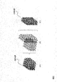
- FIG. 3 is a diagram for explaining an initial position and a target position of the robot.
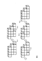
- FIG. 4 is a diagram for explaining a state of movement of a void.
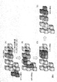
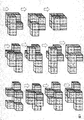
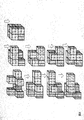
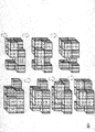
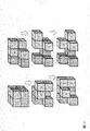
- FIG. 3 is a diagram for explaining movement of each robot.
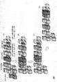
- FIG. 3 is a diagram for explaining movement of each robot.
- FIG. 3 is a diagram for explaining movement of each robot.
- FIG. 3 is a diagram for explaining movement of each robot.
- FIG. 3 is a diagram for explaining movement of each robot.
- FIG. 3 is a diagram for explaining movement of each robot.
- FIG. 3 is a diagram for explaining movement of each robot.
- FIG. 3 is a diagram for explaining movement of each robot.
- FIG. 3 is a diagram for explaining movement of each robot.
- FIG. 3 is a diagram for explaining movement of each robot.
- FIG. 3 is a diagram for explaining movement of each robot.
- FIG. 3 is a diagram for explaining movement of each robot.
- FIG. 3 is a diagram for explaining movement of each robot.
- FIG. 3 is a diagram for explaining an example of a robot unit.
- FIG. 2 is a block diagram illustrating a control device according to the first embodiment.
- 3 is a flowchart illustrating a control method according to the first embodiment.
- FIG. 4 is a block diagram for explaining a control device according to a second embodiment.
- 9 is a flowchart for explaining a control method according to the second embodiment.
- FIG. 9 is a block diagram for explaining a control device according to a third embodiment.
- 9 is a flowchart illustrating a control method according to a third embodiment.
- a number of robots control the formation of an arbitrary platoon as an initial platform formation state and move the platoon to the target platoon formation state, which is the desired arbitrary platform formation state, while maintaining the robots in contact with each other.
- a cubic robot capable of moving by sliding surfaces that are in contact with each other as illustrated in FIG. 1, for example.
- the transformation from the platoon at the initial position to the platoon at the target position is performed by moving a plurality of robots. It will be realized.
- a robot for example, as shown in FIG. 1, another robot exists in one of six squares around the robot in the vertical and horizontal height directions (hereinafter, also referred to as “up, down, left, right, front and back directions”). It is assumed that the robot moves while maintaining the state (shared with other robots).
- This method has the advantage that one robot itself can accurately measure the movement amount of one operation by moving a distance corresponding to the size of one robot. Also, by measuring the relative positions of adjacent robots sharing one surface, the position of each robot in the entire group of robots can be easily known.
- the robot realizes movement by using a robot group including four robots as shown in the right diagram of FIG. 4 as a minimum unit (robot unit), so that the total number p of robots is a multiple of four.
- Each cube in FIG. 1 indicates the position of each robot. There can be only one robot in each cube. Each robot is assumed to be stationary if there is an obstacle or another robot in the direction to move. Note that a cubic space where a robot can exist is also called a mass or a lattice.
- the colored square indicates the position where the robot exists.
- the position where the robot exists in FIG. 2 (A) indicates a set of initial positions of the robot (initial row formation state), and the position where the robot exists in FIG. 2 (C) indicates a set of target positions of the robot (target row formation state). ). As shown in FIG. 2B, the set of target positions and the set of initial positions are in contact.
- An area represented by a set of target positions is also referred to as a target platoon area.
- each initial position and each target position are adjacent to the other initial position and the target position in at least one of the vertical and horizontal height directions, and the platoon shape at the initial position and the target position of the robot is each one block. Of any shape.
- an intermediate platoon formation state that is adjacent to the immediately preceding platoon formation state between the initial platoon formation state and the target platoon formation state, respectively.
- a plurality of sets are formed, and the above-mentioned formation is repeated as the initial formation formation state and the target formation formation state, respectively.
- a set of initial positions (Xr0 [i], Yr0 [i], Zr0 [i]) of the robot is s, and a set of target positions (Xre [i], Yre [i], Zre [i]) is g.
- each state (robot position and action) of the robot i is represented by a discrete value.
- a room is represented by a three-dimensional space composed of a rectangular coordinate system of X, Y, and Z
- each position is represented by values obtained by discretely representing the X, Y, and Z axes. That is, the room (three-dimensional space) is partitioned by grids, and each grid corresponds to each position. In each grid, “presence / absence” of an obstacle is set in advance.
- the action subject being a robot is each robot arranged in a room.
- the action a of the robot i (i is a robot number) takes any one of a total of seven types, i.e., stationary and moving one grid in the vertical and horizontal directions.
- the void referred to here is a void formed in a certain position after a certain robot moves to another position.
- a void is a virtual entity that moves in a direction opposite to the direction in which the robot moves.
- the amount of search computation explodes because the focus is on the movement of multiple robots.However, if the viewpoint is changed and attention is paid to the movement of the void, the movement of many robots
- the planning problem can be considered as a single void motion plan, which is suitable for reducing the search calculation load.
- FIG. 3 shows a state in which the void moves as the robot moves.
- Reference 1 employs the structure of an eight-mass robot fully filled, voids must be intentionally created in the structure for the movement of the robot, so that adjacent There were many inconveniences between the robots that did not move. Therefore, it was difficult to simultaneously move each robot to reach the target position when the entire shape of the platoon was deformed.
- a robot unit having a space around it is used as a basic component of a platoon, and the platoon is configured by connecting a plurality of the robot units, and the robot moves while maintaining the robot unit.
- the platoon is configured by connecting a plurality of the robot units, and the robot moves while maintaining the robot unit.
- four adjacent robots are set as one unit (robot unit), and the robot moves while maintaining the robot unit.
- one robot unit is formed for every four robots, and the four robots forming one robot unit move while maintaining adjacent states.
- the group of robot units is controlled so as to share at least one surface for each robot unit and move while touching each other.
- the platoon deformation is performed while maintaining the connectivity. It is also assumed that four robots belonging to the same robot unit are the same (homogeneous). That is, in the same robot unit, it does not matter which robot is at which position in the unit.
- the robot unit may be configured to satisfy the following conditions. That is, the robot unit is (1) a cubic space (M ⁇ 2, where the length of one robot is 1) in each axial direction in a three-dimensional orthogonal coordinate system ( Hereinafter, this space is referred to as a metamodule.) (In other words, the robot unit occupies a part of the metamodule), and (2) the number of robots included in the robot unit in the metamodule, The number of portions (i.e., voids) other than the robot unit in the metamodule is equal, and (3) a structure in which M robots are adjacent in each axial direction. For example, the robot unit illustrated in FIG.
- the present invention is characterized by realizing a reduction in calculation load by using, as a basic unit, a configuration in which a robot unit has a space around it.
- a robot unit there will be described a case of a four consisting robot structure robot unit shown in FIG. 4, of M 3 pieces of the size of the meta-module in the above (1) The same effect can be obtained if the robot unit is configured to satisfy the conditions of (3).
- the robot unit formed by the four robots is a unit of one cell (in the present embodiment, this unit is also referred to as a “cell unit” or a “position unit”), and one cell unit is one state.
- the initial state be a set S
- the target state be a set G among the states consisting of a set of robot unit positions that can be taken as
- the set S may be referred to as a set S of initial positions or an initial position S.
- each robot unit j to which each robot i belongs is invariable at any time of the row control.
- the initial position of each robot unit j is (Xr_u0 [j], Yr_u0 [j], Zr_u0 [j]), and the target position is (Xr_ue [j], Yr_ue [j], Zr_ue [j]).
- moving a robot belonging to a robot unit may be abbreviated to moving the robot unit.
- the formation of the platoon can be performed in a smaller number of steps than in the conventional case where the control of movement is performed in units of robots composed of eight robots. Deformation becomes possible.
- the target positions (Xr_ue [j], Yr_ue [j], Zr_ue [j]) of the robot unit j remain in the gap, and the target positions (Xr_ue [j], Yr_ue [j], Zr_ue [j Assume that there are four robots belonging to the robot unit j ′ in the position of the robot unit adjacent to []) (FIG. 5A). In this case, there are no unconnected portions in the platoon consisting of p robots, and in each robot unit, there are four voids through which the robots can pass.
- the heterogeneous row control is completed.
- the operation of exchanging the positions of the robots which is conventionally required, is replaced with the operation of exchanging the positions of the robots belonging to the robot unit j ′ and the robots belonging to the robot unit j.
- the movement amount required from the initial position to the target position is substantially the same as the movement amount without replacement, and other movement is not required. . That is, by this method, the entire deformation of the platoon and the replacement of the robot position are performed simultaneously.
- the time at which each robot unit at the initial position S starts to move to the target position is determined by the time at which the robot unit that started moving to the target position immediately before reached the target position. (The robot unit moves one by one), but if the space created by the four mass robot units in the robot structure is fully used, multiple robot units can be moved to the target position at the same time. It is also possible to make it.
- the robot unit that is about to start moving can start moving within a certain period of time from the start time of the robot unit that started moving immediately before, the time required for the entire deformation is calculated as the robot unit. It can be proportional to the first power of a number.
- ⁇ Describe the method for that.
- the position of the robot unit in the initial position S in contact with the target position G is a connection position Gate_S (X_Gate, Y_Gate, Z_Gate), and all robot units Is to enter the target position G via the connection position Gate_S.
- the robot unit starts moving preferentially starting from the one with the largest Manhattan distance ⁇ (j) from the connection position Gate_S.
- the robot unit exchanges positions, all the robot units subsequent to the robot unit whose positions are exchanged stop operating for at least two hours.
- the ⁇ value of the unit of the control object that is about to start moving is ⁇ (j)
- the ⁇ value of the initial position of the unit of the control object that started moving immediately before is ⁇ (j ⁇ 1)
- t w ⁇ (j ⁇ 1) ⁇ (j) + ⁇
- the control object unit that is about to start moving is the control object that has just started moving. The movement starts after tw time steps from the unit movement start time.
- the control object unit whose movement is to be started has the same ⁇ value as the initial position of the control object unit whose movement has been started immediately before, the control object unit whose movement is to be started is 1
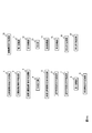
- the mobile robot includes a position distance calculation command transmitting unit 1, a position distance calculation command transfer unit 2, a return position distance calculation command transmission unit 3, a direction storage unit 4, a return position distance calculation command transfer unit 5, Operation time notification command transmission unit 6, operation time notification command transfer unit 7, first movement unit 8, movement start command transmission unit 9, movement start command transfer unit 10, second movement unit 11, third movement unit 12, determination unit 13, a fourth moving unit 14, a fifth moving unit 15, a waiting command transmitting unit 16, and a waiting command transferring unit 17, for example.
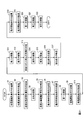
- the method of controlling the mobile robot is realized by each unit of the mobile robot performing, for example, FIG. 17 and the processing of steps S1 to S17 described below.
- step S1 to step S5 are processes for grasping the row structure at the initial position S.
- the processing from step S6 to step S17 is processing for moving the robot unit.
- a transformation start command is sent from the user to the robot unit j_root at the connection position Gate_S. It is assumed that the deformation start command includes platoon form information that is information on the target position G of each robot.
- the position distance calculation command may be referred to as a position distance calculation command MANHATTAN_COM
- the relative position may be referred to as a relative position (Xr, Yr, Zr)
- the number of transmission transfers may be referred to as a transmission transfer number N_manhattan.
- the initial value of the relative position (Xr, Yr, Zr) is (0, 0, 0), and the initial value of the number N_manhattan of transmissions is zero.
- the position-distance calculation command transfer unit 2 increments the number of transmission transfers included in the position-distance calculation command, and sets the position distance according to the direction in which the position-distance calculation command is received.
- the relative position included in the calculation instruction is updated, and the position distance calculation instruction including the incremented transmission transfer count and the updated relative position is transferred only once to adjacent robot units other than the robot unit that transmitted the position distance calculation instruction. (Step S2).
- the position / distance calculation command transfer unit 2 does not transfer the position / distance calculation command MANHATTAN_COM to each robot that has transmitted it to itself. As a result, it is possible to prevent the position / distance calculation instruction MANHATTAN_COM from being transmitted / received infinitely many times in the robot structure.
- the return position distance calculation command transmitting unit 3 When the robot unit first receives the position distance calculation command, the return position distance calculation command transmitting unit 3 includes the incremented transmission transfer count and the updated relative position in the robot unit that has transmitted the position distance calculation command. A return position distance calculation command is transmitted (step S3).
- the return position distance calculation command may be referred to as a return position distance calculation command RETURN_MANHATTAN_COM.
- the value of the transmission transfer count N_manhattan when the position distance calculation command MANHATTAN_COM is first received is the Manhattan distance of the robot unit j_root from the robot unit j_root.
- the direction storage unit 4 stores the direction of the robot unit that has transmitted the position distance calculation command as the root direction (step S4).
- each robot sends some information to the robot unit j_root in the direction of the root.
- each robot that has received each return position distance calculation instruction performs the process of step S5, so that each return position distance calculation instruction finally reaches the robot unit j_root.
- the operation time notification command transmission unit 6 determines whether each of the robots is based on the relative position included in the return position distance calculation command. The movement start time of each robot unit is determined based on the position of the unit, and an operation time notification command including the movement start time is transmitted to the adjacent robot unit (step S6).
- the operation time notification command transmitting unit 6 grasps the Manhattan distance of each robot unit, and in the descending order of the Manhattan distance, the order of starting the movement operation to the target position G of each robot unit, and the start of movement between the robot units. Determine the scheduled time.
- the operation time notification instruction may be referred to as an operation time notification instruction START_TIME_COM.
- the operation time notification instruction START_TIME_COM contains information on the movement start time of each robot.
- the operation time notification instruction may be referred to as an operation time notification instruction START_TIME_COM.
- the operation time notification instruction START_TIME_COM contains information on the movement start time of each robot.
- the robot unit is the robot unit that starts moving first, and when the operation time notification command is received, the first moving unit 8 moves the robot toward the connection position (step S8).
- the robot unit that starts moving first starts the movement operation to the target position G passing through the connection position Gate_S after receiving the operation time notification instruction START_TIME_COM. .
- the robot unit j_1 which starts moving first receives the command START_TIME_COM last among all the robot units, no other robot unit receives the command START_TIME_COM by this method. .
- the robot unit j_1 that has started moving first moves in the root direction by the operation shown in FIGS. After that, the robot unit j_1 sends an instruction ASK_TO_ROOT_COM for asking the direction of the root to the robot unit forming an 8-mass robot unit together with itself, and learns the root direction by a return instruction RETURN_TO_ROOT in response thereto. Then move to the root direction. At this time, the operations of FIGS. 9 and 10 are used. Thereafter, this operation is repeated until the robot unit j_1 reaches the position of the robot unit j_root (connection position Gate_S).
- the movement start command may be described as a movement start command MOVE_STRAT_COM.
- the robot unit j_1 is a robot unit scheduled to start moving to the target position G which passes through the connection position Gate_S after a predetermined time (time difference until the start time of movement of the next robot unit) has elapsed after the start of movement.
- the robot unit j_2 that has received the movement start command MOVE_START_COM starts moving to the target position G passing through the connection position Gate_S. Thereafter, the robot unit j_2 will start moving to the next target position G through the connection position Gate_S after a predetermined time after the start of movement (the time difference until the start time of movement of the next robot unit).
- a movement start command MOVE_STRAT_COM is transmitted to the unit j_3.
- Steps S9 to S12 are repeated until all the robot units at the initial position S start moving to the target position G passing through the connection position Gate_S.
- the third moving unit 12 acquires the target position of the own robot unit and the path for reaching the target position of the own robot unit from the robot unit j_root, The own robot unit is moved according to the acquired target position and path (step S12).
- the third moving unit 12 of each robot unit j_k arriving at the connection position Gate_S gives the robot unit j_root a target position in its own G and an optimal path to reach it (the robot unit position in G reaching there).
- the determination unit 13 determines whether or not there is another robot unit at an adjacent position to be moved (step S13).
- the robot unit j_k that has started to move to its own target position within G first has its own robot unit j_k ', which forms an eight-mass robot unit, with the robot unit j_k in the direction in which the robot unit j_k is about to move.
- the robot unit j_k returns the presence / absence of an adjacent robot unit in the moving direction of the robot unit j_k to the robot unit j_k using the adjacent robot unit confirmation command RETURN_TARGET_EXIST_COM.
- the determination unit 13 of the robot unit j_k can determine whether or not there is another robot unit at an adjacent position to be moved.
- the robot unit j_k that has received the adjacent robot unit confirmation command RETURN_TARGET_EXIST_COM is the case where there is already another robot unit in the direction that the robot unit j_k is going to move, and the position to be moved is not its own target position In this case, for example, the movement is performed by the operation shown in FIG. 9 or FIG.
- the robot unit j_k that has received the adjacent robot unit confirmation command RETURN_TARGET_EXIST_COM moves by the operation shown in FIG. 13 or FIG. 14 if there is no other robot unit in the direction that the robot unit j_k is about to move from now. Do.
- the fourth moving unit 14 of the robot unit j_k Is an adjacent robot unit confirmation command that asks the robot unit j_k ', which forms an 8 unit robot unit, for information on whether there is a robot unit adjacent to the robot unit that is already in the direction that the robot unit j_k is about to move.
- the robot unit j_k transmits the adjacent robot unit confirmation command ASK_GOAL_NEIGHBOR_COM to the robot unit at the target position of the robot unit j_k, and the robot unit at the target position of the robot unit j_k that receives it transmits the robot adjacent to itself.
- the return adjacent robot unit confirmation command RETURN_GOAL_NEIGHBOR_COM is transferred to the robot unit j_k via the robot unit j_k '.
- the fourth moving unit 14 moves its own robot unit to an adjacent position to be moved.
- the waiting command transmitting unit 16 transmits a waiting command including a predetermined waiting time to an adjacent robot unit (step S16).
- the robot unit j_k After receiving the adjacent robot unit confirmation command RETURN_GOAL_NEIGHBOR_COM, the robot unit j_k transmits a wait command WAIT_COM to the subsequent moving robot unit.
- the wait instruction may be referred to as a wait instruction WAIT_COM.
- the predetermined waiting time is, for example, the time + ⁇ required for the robot unit j_k to move from the position adjacent to the target position to the target position by the operation shown in FIG. 11 or 12.
- ⁇ is a predetermined time of 0 or more.
- the waiting command transfer unit 17 stops the movement of its own robot unit for the waiting time included in the waiting command, and transfers the waiting command only once to the adjacent robot unit. (Step S17).
- each moving robot unit that has received the wait command WAIT_COM thereafter stops its operation for the time specified by the command.
- the wait instruction WAIT_COM is propagated to each robot unit in the same manner as the instruction MANHATTAN_COM.
- the operation of replacing the robot unit position is performed in the target position G, but may be performed in the initial position S.
- the order in which the moving robot unit passes through the connection position Gate_S and enters the target position G must be in the order of the smallest Manhattan distance of the target position of each robot unit from the connection position Gate_S.
- the condition that the Manhattan distance of the robot j from the robot unit j_root is larger than that of the robot unit in the initial position S adjacent to the robot unit j at the present time must be satisfied. No.
- the robot unit j_k is the robot unit that should pass through the next connection position Gate_S.
- the robot unit is followed from the robot unit j_k to the adjacent robot unit so that the Manhattan distance is increased, and the robot unit finally located in S at that time is j_move, and the robot unit j_move is first replaced with the robot unit j_k To the position.
- the robot unit j_move and the robot unit j_k are exchanged by the operation shown in FIG. 11 or FIG. 12, and then the robot unit j_k is moved to the connection position Gate_S.
- the robot unit j_k moves within the target position G as in the first embodiment.
- the setting of the movement start time for each robot is the same as in the first embodiment.
- a second embodiment of a mobile robot and a mobile robot control method that realizes the above method by an algorithm of a distributed control method will be described below.
- the above-described robot operation is realized by a computer mounted in each robot unit and a distributed algorithm for realizing the communication by using communication between adjacent robots.
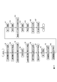
- the mobile robot includes a position distance calculation command transmission unit 1, a position distance calculation command transfer unit 2, a return position distance calculation command transmission unit 3, a direction storage unit 4, a return position distance calculation command transfer unit 5, It includes, for example, an operation start command transmission unit 18, an operation start command transfer unit 19, a first moving unit 20, a second moving unit 21, and a third moving unit 22.
- the method of controlling the mobile robot is realized by each unit of the mobile robot performing, for example, FIG. 19 and steps S1 to S5 and steps S18 to S22 described below.
- step S1 to step S5 are processes for grasping the row structure at the initial position S.
- the processing from step S18 to step S22 is processing for moving a robot unit.
- the position distance calculation command transmitting unit 1, the position distance calculation command transfer unit 2, the return position distance calculation command transmission unit 3, the direction storage unit 4, and the return position distance calculation command transfer unit 5 Steps S1 to S5 are performed.
- the operation start command transmitting unit 18 determines whether each robot based on the relative position included in the return position distance calculation command. The movement start time of each robot unit is determined based on the position of the unit. .., K from the smallest Manhattan distance from the Gate_S of the target position in G, and the robot unit j_k entering G in the ascending order of k is determined.
- the operation start command transmission unit 18 starts the robot movement in the robot unit j_root in consideration of the robot position replacement within the initial position S described above. Set the time.
- the first operation start instruction START_MOVE_COM includes a robot unit j_1 that should pass through Gate_S first, a robot unit j_move that is located farthest from the robot unit j_1 in a direction in which the Manhattan distance can be increased, and a robot unit j_move. From the robot unit j_1.
- the operation start instruction transmission unit 18 of the robot unit j_root After transmitting the first operation start instruction START_MOVE_COM, the operation start instruction transmission unit 18 of the robot unit j_root has passed a predetermined time (the movement start time interval determined by the Manhattan distance ⁇ from the Gate_S of the robot unit j_move + the waiting time for replacement). After that, the second operation start command START_MOVE_COM is transmitted.
- the second operation start instruction START_MOVE_COM includes the robot unit j_2 that should pass through the connection position Gate_S for the second time, the farthest robot unit j_move that can be reached from the robot unit j_2 in a direction that increases the Manhattan distance, and the robot It contains the route information from the unit j_move to the robot unit j_2.
- the first moving unit 20 of the robot unit j_move that has received the first operation start command START_MOVE_COM moves the robot unit j_move to the position of the robot unit j_1.
- the following is an example of the switching operation of the positions of the robot unit j_move and the robot unit j_k.
- the first moving unit 20 of the robot unit j_move compares the robot unit j_k with the robot unit adjacent to the robot unit j_k.
- the robot unit j_k returns a return adjacent robot unit confirmation command RETURN_GOAL_NEIGHBOR_COM that returns information on the presence or absence of a robot unit adjacent to itself.
- the robot unit j_k (k 1, 2, 3,..., P / 4) that has started moving, for example, first moves in the root direction by the operation shown in FIG. 9 or FIG. Thereafter, each robot unit transmits, for example, an instruction ASK_TO_ROOT_COM for asking the root direction to a robot unit forming an 8-mass robot unit together with itself, and learns the root direction by a return instruction RETURN_TO_ROOT in response thereto. Then, it moves in the root direction (use the operation of FIG. 9 or FIG. 10). Thereafter, this is repeated until the robot unit j_k reaches the position (connection position Gate_S) of the robot unit j_root.
- the third moving unit 22 acquires the target position of the own robot unit and the path for reaching the target position of the own robot unit from the robot unit j_root, The own robot unit is moved according to the acquired target position and path (step S22).
- the third moving unit 22 of each robot unit j_k arriving at the connection position Gate_S sends the target position in its own G and the optimal path to it to the robot unit j_root (the robot unit position in G reaching there). After sending the command REQUEST_PATH_TO_GOAL_COM requesting the information (assuming that everything is buried) and receiving the return command RETURN_PATH_TO_GOAL_COM from the robot unit j_root, start moving to the target position in G according to the received path information I do.
- each robot unit j to which each robot i belongs is invariable at any time of the row control.
- the initial position of each robot unit j is (Xr_u0 [j], Yr_u0 [j], Zr_u0 [j]), and the target position is (Xr_ue [j], Yr_ue [j], Zr_ue [j]).
- the point where the Manhattan distance from the connection position Gate_S is shortest and the movement to the target position G is preferentially performed is followed by the white point.
- the only difference from the first and second embodiments is that the robot passes through the connection position Gate_S in ascending order of the Manhattan distance from the connection position Gate_S in the target position G.
- Other points are the same as the first embodiment and the second embodiment.
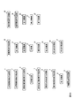
- the mobile robot includes a position distance calculation command transmission unit 1, a position distance calculation command transfer unit 2, a return position distance calculation command transmission unit 3, a direction storage unit 4, and a return position distance calculation.
- Command transfer unit 5 operation time notification command transmission unit 6, operation time notification command transfer unit 7, first movement unit 8, movement start command transmission unit 9, movement start command transfer unit 10, second movement unit 11, third movement Unit 12, determination unit 13, fourth moving unit 14, fifth moving unit 15, waiting command transmitting unit 16, waiting command transferring unit 17, operation starting command transmitting unit 18, operation starting command transferring unit 19, first moving unit 20,
- a second moving unit 21 and a third moving unit 22 are provided, for example.
- the method of controlling the mobile robot is realized by each unit of the mobile robot performing, for example, FIG. 21 and steps S1 to S22 described below.
- step S1 to step S17 the position distance calculation command transmitting unit 1, the position distance calculation command transfer unit 2, the return position distance calculation command transmission unit 3, the direction storage unit 4, and the return position distance calculation command transfer unit 5, Operation time notification command transmission unit 6, operation time notification command transfer unit 7, first movement unit 8, movement start command transmission unit 9, movement start command transfer unit 10, second movement unit 11, third movement unit 12, determination unit
- the processing from step S1 to step S17 is performed by the 13, the fourth moving unit 14, the fifth moving unit 15, the waiting command transmitting unit 16, and the waiting command transferring unit 17.
- the operation time notification command transmitting unit 6 determines the movement start time of each robot unit such that the movement to the target position G is started preferentially from the robot unit whose Manhattan distance from the connection position Gate_S is short (step S6).
- the processes of steps S1 to S5 and steps S18 to S22 are performed by the operation start command transmitting unit 18, the operation start command transfer unit 19, the first moving unit 20, the second moving unit 21, and the third moving unit 22.
- the operation start command transmission unit 18 determines the movement start time of each robot so as to pass through the connection position Gate_S in ascending order of the Manhattan distance from the connection position Gate_S in the target position G (step S18). .
- Step S1 to Step S5 by the second position distance calculation command transmission unit 1, position distance calculation command transfer unit 2, return position distance calculation command transmission unit 3, direction storage unit 4, and return position distance calculation command transfer unit 5 May not be performed.
- the first-time position distance calculation command transmission unit 1, position distance calculation command transfer unit 2, return position distance calculation command transmission unit 3, direction storage unit 4, and return position distance calculation command transfer unit 5 perform steps S1 to S5.
- the time required for the row control operation can be shortened by simultaneously performing the deformation operation of the entire shape and the replacement of the robot position after the deformation without using separate processes.
- a program describing this processing content can be recorded on a computer-readable recording medium.
- a computer-readable recording medium for example, any recording medium such as a magnetic recording device, an optical disk, a magneto-optical recording medium, and a semiconductor memory may be used.
- each unit may be configured by executing a predetermined program on a computer, or at least a part of the processing may be realized by hardware.
Landscapes
- Engineering & Computer Science (AREA)
- Automation & Control Theory (AREA)
- Robotics (AREA)
- Mechanical Engineering (AREA)
- Remote Sensing (AREA)
- Aviation & Aerospace Engineering (AREA)
- Radar, Positioning & Navigation (AREA)
- Physics & Mathematics (AREA)
- General Physics & Mathematics (AREA)
- General Health & Medical Sciences (AREA)
- Orthopedic Medicine & Surgery (AREA)
- Health & Medical Sciences (AREA)
- Control Of Position, Course, Altitude, Or Attitude Of Moving Bodies (AREA)
- Manipulator (AREA)
Abstract
隊列制御動作にかかる時間を短縮することができる制御技術を提供する。移動ロボットは、位置距離計算命令送信部1、位置距離計算命令転送部2、返信位置距離計算命令送信部3、方向記憶部4、返信位置距離計算命令転送部5、動作時刻告知命令送信部6、動作時刻告知命令転送部7、第一移動部8、移動開始命令送信部9、移動開始命令転送部10、第二移動部11、第三移動部12、判定部13、第四移動部14、第五移動部15、待ち命令送信部16及び待ち命令転送部17を例えば備えている。
Description
本発明は、複数のロボットの行動を制御する技術に関する。例えば、複数のロボットを、初期位置における隊列形成状態から協調して移動させ、障害物を回避させ、目標位置で隊列形成をさせるための各ロボットの行動計画を求めるロボット協調制御技術に関する。
近年、多数の自律移動ロボットを効率的に制御にするための研究が活発に行われている。その任務内容は、人の入れない箇所の監視、物品の搬送などさまざまであるが、多数のロボットの協調動作による隊列形成を効率的に行わせるための技術が求められており盛んに研究が行われている。
特に、ロボットの隊列制御の中でも、ロボット同士が互いに接したままの状態で、アメーバのように全体で移動を行うという仮定の下でのロボット隊列制御においては、ロボット同士の相対的な位置関係から、各ロボットの絶対位置の決定が可能であるという利点と、付加的な位置計測用の装備を必要としないという利点があり、そのようなロボットの研究も行われている(例えば、非特許文献1,2参照。)。
非特許文献1は、全てのロボットが同じ性質を持つ(ホモジニアス)という前提の下で、任意の初期隊列形成状態から目的隊列形成状態へ変形する隊列制御を実現する方法が開示されている。ここでは、8つのロボットを1つの単位として移動させることで、従来よりも効率的な隊列制御を実現している。
非特許文献2では、各矩形ロボットが異なる性質を持つ(ヘテロジニアス)という前提の下で、任意の形状隊列から他の形状隊列へ変形する隊列制御の方法が開示されている。
このような、多数のロボットによる効率的な隊列形成を実現するには、それぞれのロボットの配置、動作順序などを事前に計画することが重要である。このような計画においては、当然ながら、複数のロボットが動作する実環境における障害物の存在や経路の形状なども十分に考慮しなければならない。
Kawano, H., "Complete Reconfiguration Algorithm for Sliding Cube-shaped Modular Robots with only Sliding Motion Primitive", 2015 IEEE/RSJ International Conference on Intelligent Robots and Systems(IROS 2015), pp.3276-3283, September 2015, Hamburg, Germany.
R. Fitch, Z. Butler, D. Rus, "Reconfiguration Planning for Heterogeneous Self-Reconfiguring Robots", in Proc.2003 IEEE/RSJ Int. Conf. Intelligent Robots and Systems, pp. 2460-2467, Las Vegas, NV, Oct., 2003.
非特許文献2では、各ロボットが接した状態での動作を想定し、各ロボットが異なる特性(ヘテロジニアス)である、つまり、各ロボットの目標位置が特定されている場合の隊列制御を実現している。このような隊列制御は、例えば、カメラを搭載したロボット、車輪を搭載したロボット等の個々に異なる役割がある各ロボットをロボット隊列内の適切な位置に配置させつつ、隊列の形状を制御するといった運用に適している。
非特許文献1はホモジニアスを前提としており、隊列変形後の各ロボットの位置が保証されないため、ヘテロジニアスを前提とするような隊列形成の問題に適用することができない。
非特許文献2は、ヘテロジニアスを前提とする隊列形成を行うことができるが、隊列全体の形状の変形動作と、変形後のロボット位置入れ替えを別個のプロセスとして行わなければならない。つまり、まずロボットの位置は問わずに形状(隊列)を目的隊列に変形する前に、各ロボットの位置が正しい目標位置となるように各ロボットの位置の入れ替えを行うための別の隊列形態をとり、ロボットの位置の入れ替えを行うのである。そのロボット位置入れ替えの処理に非常に時間を要するため、全体として隊列制御にかかる時間が長いという問題がある。
このような現状に鑑みて、本発明は、隊列制御動作にかかる時間を短縮することができる制御装置、方法及びプログラムを提供することを目的とする。
この発明の一態様による移動ロボットは、移動ロボットは複数のロボット単位で構成されているとし、各ロボット単位の周囲には他のロボット単位を構成するロボットが移動可能な空隙があり、各ロボット単位には所定の初期位置及び所定の目標位置が定められており、所定の初期位置の集合と所定の目標位置の集合とは接しているとし、所定の初期位置の集合に含まれる位置であって所定の目標位置の集合に接している位置の1つを接続位置とし、移動ロボットは所定の初期位置から接続位置を通って所定の目標位置に移動するとして、複数のロボット単位のそれぞれについて、当該ロボット単位が接続位置にあるロボット単位j_rootである場合に、それぞれ所定の初期値に設定された、接続位置からの相対位置と位置距離計算命令の送信転送回数とを含む位置距離計算命令を隣接するロボット単位に送信する位置距離計算命令送信部と、位置距離計算命令を受信した場合に、位置距離計算命令に含まれる送信転送回数をインクリメントし、位置距離計算命令を受信した方向に応じて位置距離計算命令に含まれる相対位置を更新し、インクリメントした送信転送回数及び更新した相対位置を含む位置距離計算命令を、位置距離計算命令を送信してきたロボット単位以外の、隣接するロボット単位に一度だけ転送する位置距離計算命令転送部と、位置距離計算命令を最初に受信した場合に、位置距離計算命令を送信してきたロボット単位に、インクリメントした送信転送回数及び更新した相対位置を含む返信位置距離計算命令を送信する返信位置距離計算命令送信部と、位置距離計算命令を最初に受信した場合に、位置距離計算命令を送信してきたロボット単位の方向をroot方向として記憶する方向記憶部と、返信位置距離計算命令を受信した場合に、方向記憶部から読み込んだroot方向に受信した返信位置距離計算命令を転送する返信位置距離計算命令転送部と、複数のロボット単位のそれぞれについて、当該ロボット単位がロボット単位j_rootであり、全てのロボットが送信した返信位置距離計算命令を受信した場合に、返信位置距離計算命令に含まれる相対位置に基づく各ロボット単位の位置に基づいて、各ロボット単位の移動開始時刻を決定し、移動開始時刻を含む動作時刻告知命令を隣接するロボット単位に送信する動作時刻告知命令送信部と、動作時刻告知命令を受信した場合に、動作時刻告知命令を隣接するロボット単位に一度だけ転送する動作時刻告知命令転送部と、最初に移動を開始するロボット単位であり動作時刻告知命令を受信した場合に、接続位置に向けてロボットを移動させる第一移動部と、移動開始後所定の時間が経過した場合に、次に移動するロボット単位宛ての移動開始命令を隣接するロボット単位に送信する移動開始命令送信部と、移動開始命令を受信した場合に、移動開始命令を隣接するロボット単位に一度だけ転送する移動開始命令転送部と、移動開始命令を受信した場合に、接続位置に向けてロボットを移動させる第二移動部と、接続位置に到達した場合に、ロボット単位j_rootから自身のロボット単位の目標位置と、自身のロボット単位の目標位置に到達するためのパスとを取得し、取得した目標位置及びパスに従って自身のロボット単位を移動させる第三移動部と、隣接し移動しようとする位置に他のロボット単位があるかどうかを判定する判定部と、隣接し移動しようとする位置に他のロボット単位があり、隣接し移動しようとする位置が自身のロボット単位の目標位置である場合には、自身のロボット単位を隣接し移動しようとする位置に移動させる第四移動部と、複数のロボット単位のそれぞれについて、当該ロボット単位が他のロボット単位である場合に、自身のロボット単位が隣接し移動しようとする位置に移動した後に、他のロボット単位を他のロボット単位の目標位置及びパスに従って移動させる第五移動部と、複数のロボット単位のそれぞれについて、当該ロボット単位が他のロボット単位である場合に、所定の待ち時間を含む待ち命令を隣接するロボット単位に送信する待ち命令送信部と、待ち命令を受信した場合に、待ち命令に含まれる待ち時間だけ自身のロボット単位の移動を停止すると共に、待ち命令を隣接するロボット単位に一度だけ転送する待ち命令転送部と、を含む。
この発明の一態様による移動ロボットは、移動ロボットは複数のロボット単位で構成されているとし、各ロボット単位の周囲には他のロボット単位を構成するロボットが移動可能な空隙があり、各ロボット単位には所定の初期位置及び所定の目標位置が定められており、所定の初期位置の集合と所定の目標位置の集合とは接しているとし、所定の初期位置の集合に含まれる位置であって所定の目標位置の集合に接している位置の1つを接続位置とし、移動ロボットは所定の初期位置から接続位置を通って所定の目標位置に移動するとして、複数のロボット単位のそれぞれについて、当該ロボット単位が接続位置にあるロボット単位j_rootである場合に、それぞれ所定の初期値に設定された、接続位置からの相対位置と位置距離計算命令の送信転送回数とを含む位置距離計算命令を隣接するロボット単位に送信する位置距離計算命令送信部と、位置距離計算命令を受信した場合に、位置距離計算命令に含まれる送信転送回数をインクリメントし、位置距離計算命令を受信した方向に応じて位置距離計算命令に含まれる相対位置を更新し、インクリメントした送信転送回数及び更新した相対位置を含む位置距離計算命令を、位置距離計算命令を送信してきたロボット単位以外の、隣接するロボット単位に一度だけ転送する位置距離計算命令転送部と、位置距離計算命令を最初に受信した場合に、位置距離計算命令を送信してきたロボット単位に、インクリメントした送信転送回数及び更新した相対位置を含む返信位置距離計算命令を送信する返信位置距離計算命令送信部と、位置距離計算命令を最初に受信した場合に、位置距離計算命令を送信してきたロボット単位の方向をroot方向として記憶する方向記憶部と、返信位置距離計算命令を受信した場合に、方向記憶部から読み込んだroot方向に受信した返信位置距離計算命令を転送する返信位置距離計算命令転送部と、複数のロボット単位のそれぞれについて、当該ロボット単位がロボット単位j_rootであり、全てのロボットが送信した返信位置距離計算命令を受信した場合には、返信位置距離計算命令に含まれる相対位置に基づく各ロボット単位の位置に基づいて、各ロボット単位の移動開始時刻を決定し、k=1,…,Kとして、ロボット単位j_kの移動開始時刻になった場合に、ロボット単位j_kと、ロボット単位j_kからたどっていける場所にあり接続位置からのマンハッタン距離が最も大きい位置にあるロボット単位j_moveと、ロボット単位j_moveの位置からロボット単位j_kの位置への経路情報とを含む動作開始命令を隣接するロボット単位に送信する動作開始命令送信部と、動作開始命令を受信した場合に、動作開始命令を隣接するロボット単位に一度だけ転送する動作開始命令転送部と、ロボット単位j_moveについて、動作開始命令を受信した場合には、ロボット単位j_moveをロボット単位j_kの位置に移動させる第一移動部と、ロボット単位j_kについて、ロボット単位j_moveがロボット単位j_kの位置に移動した後に、ロボット単位j_kを接続位置に向けて移動させる第二移動部と、接続位置に到達した場合に、ロボット単位j_rootから自身のロボット単位の目標位置と、自身のロボット単位の目標位置に到達するためのパスとを取得し、取得した目標位置及びパスに従って自身のロボット単位を移動させる第三移動部と、を含む。
本発明によれば、隊列制御動作にかかる時間を短縮することができる。
以下、本発明の実施形態について説明する。なお、以下の説明に用いる図面では、同じ機能を持つ構成部や同じ処理を行うステップには同一の符号を記し、重複説明を省略する。
<理論的背景>
まず、行動制御システム及び方法の理論的背景について説明する。
まず、行動制御システム及び方法の理論的背景について説明する。
[問題設定]
任意の隊列形成を初期隊列形成状態として、ロボット同士が接したままの状態を維持しつつ目的とする任意の隊列形成状態である目的隊列形成状態への隊列を移動させる隊列制御を、多数のロボットが協調して行う任務を、例えば図1に例示するような、互いに接する面同士をスライドさせて移動していくことが可能な立方体型のロボットの制御を想定して実現する。この隊列制御は、図2に示すように、壁で区切られた部屋(ただし図中、壁を省略する)において、初期位置における隊列から目標位置における隊列への変形を、複数のロボットの移動によって実現するものである。
任意の隊列形成を初期隊列形成状態として、ロボット同士が接したままの状態を維持しつつ目的とする任意の隊列形成状態である目的隊列形成状態への隊列を移動させる隊列制御を、多数のロボットが協調して行う任務を、例えば図1に例示するような、互いに接する面同士をスライドさせて移動していくことが可能な立方体型のロボットの制御を想定して実現する。この隊列制御は、図2に示すように、壁で区切られた部屋(ただし図中、壁を省略する)において、初期位置における隊列から目標位置における隊列への変形を、複数のロボットの移動によって実現するものである。
ロボットについては、例えば図1に示すように、ロボットの周囲縦横高さ方向(以下「上下左右前後方向」ともいう)6マスのうち1つに他のロボットが存在している(1つの面を他ロボットと共有している)状態を維持しながら移動をするものとする。この手法では1つのロボット自身が、一個のロボットのサイズ分の距離を移動することで、一回の動作の移動量を正確に測ることができるというメリットがある。また、1つの面を共有する隣り合うロボットとの相対的な位置を計測しあうことで、ロボットの群れ全体の中での各ロボットの位置も容易に知ることができる。このため、ロボットの移動量の誤差によって、隊列が崩れるといった問題を起こしにくく、また、各ロボットの位置を把握するために付加的な位置計測用の装備を備えずとも位置の把握が可能である。また、複数のロボットを連結したように、同時に複数のロボットを移動させていくことが可能である。なお、ロボットは、隣の位置に他のロボットが存在しているか否か、障害物があるか否か、そして、自身が目標位置上にいるかどうかを知ることができるものとする。
任務を行うロボットは、p個(p≧12=4×3)であり、各ロボットは、隣接するロボットと一面以上を共有しつつ、三次元空間におけるX-Y-Z軸方向に移動可能とする。本発明では、ロボットは図4の右図に示すような4つのロボットで構成されるロボット群を最小単位(ロボット単位)として移動を実現するので、ロボットの総数pは4の倍数とする。
図1の各立方体は、それぞれのロボットの位置を示すものである。各立方体にはロボットは一個しか存在することができない。それぞれのロボットは、移動しようとする方向に障害物か他のロボットがある場合には、静止をするものと仮定する。なお、ロボットが存在しうる立方体状の空間をマス、又は、格子ともいう。図2において、色が塗りつぶされたマスはロボットが存在する位置を示す。図2(A)のロボットが存在する位置はロボットの初期位置の集合(初期隊列形成状態)を示し、図2(C)のロボットが存在する位置はロボットの目標位置の集合(目的隊列形成状態)を示す。図2(B)に示すように、目標位置の集合と初期位置の集合は接している。目標位置の集合で表される領域を目標隊列エリアともいう。このように、各初期位置及び各目標位置は、それぞれ縦横高さ方向の少なくとも何れかの方向において他の初期位置及び目標位置と隣接し、ロボットの初期位置及び目標位置での隊列形状はそれぞれ一塊の任意の形状である。
なお、初期隊列形成状態と接しない位置を目的隊列形成状態としたい場合には、初期隊列形成状態と目的隊列形成状態との間にそれぞれ直前の隊列形成状態に隣接するような中間隊列形成状態を複数設定し、時間的に隣接する隊列形成状態をそれぞれ初期隊列形成状態と目的隊列形成状態として上述の隊列形成を行うことを繰り返すことで最終的に目的隊列形態に変形させることができる。
[ロボットの座標設定]
それぞれのロボットi(iはロボット番号を表すi=0,1,2,3,…,p-1)の位置を(Xr[i],Yr[i],Zr[i])とし、初期位置を(Xr0[i],Yr0[i],Zr0[i])とし、目標位置を(Xre[i],Yre[i],Zre[i])とするとき、本問題は、初期位置に配置されたロボットが、目標位置まで移動するための行動計画を求めることと定義できる。ロボットの初期位置(Xr0[i],Yr0[i],Zr0[i])の集合をs、目標位置(Xre[i],Yre[i],Zre[i])の集合をgとする。
それぞれのロボットi(iはロボット番号を表すi=0,1,2,3,…,p-1)の位置を(Xr[i],Yr[i],Zr[i])とし、初期位置を(Xr0[i],Yr0[i],Zr0[i])とし、目標位置を(Xre[i],Yre[i],Zre[i])とするとき、本問題は、初期位置に配置されたロボットが、目標位置まで移動するための行動計画を求めることと定義できる。ロボットの初期位置(Xr0[i],Yr0[i],Zr0[i])の集合をs、目標位置(Xre[i],Yre[i],Zre[i])の集合をgとする。
[任務空間の定義]
iをロボット番号としたとき、ロボットiの各状態(ロボットの位置と行動)は離散値で表現される。部屋をX,Y,Zの直交座標系からなる3次元空間で表すと、X軸、Y軸、Z軸をそれぞれ離散化表現した値により各位置を表現する。つまり、部屋(3次元空間)は格子で区切られ、各格子が各位置に対応する。また、各格子において、障害物の「ある/なし」が予め設定されている。
iをロボット番号としたとき、ロボットiの各状態(ロボットの位置と行動)は離散値で表現される。部屋をX,Y,Zの直交座標系からなる3次元空間で表すと、X軸、Y軸、Z軸をそれぞれ離散化表現した値により各位置を表現する。つまり、部屋(3次元空間)は格子で区切られ、各格子が各位置に対応する。また、各格子において、障害物の「ある/なし」が予め設定されている。
[動作の定義]
例えば、ロボットである行動主体は部屋に配置されている各ロボットである。ロボットi(iはロボット番号)の行動aは、静止、縦横高さ方向への1格子分の移動、の計7種類のうちの何れかを取る。例えば、a∈{0,1,2,3,4,5,6}として、
0: 静止
1: 三次元空間内でX軸正方向に1格子だけ移動する
2: 三次元空間内でY軸正方向に1格子だけ移動する
3: 三次元空間内でX軸負方向に1格子だけ移動する
4: 三次元空間内でY軸負方向に1格子だけ移動する
5: 三次元空間内でZ軸正方向に1格子だけ移動する
6: 三次元空間内でZ軸負方向に1格子だけ移動する
とする。
例えば、ロボットである行動主体は部屋に配置されている各ロボットである。ロボットi(iはロボット番号)の行動aは、静止、縦横高さ方向への1格子分の移動、の計7種類のうちの何れかを取る。例えば、a∈{0,1,2,3,4,5,6}として、
0: 静止
1: 三次元空間内でX軸正方向に1格子だけ移動する
2: 三次元空間内でY軸正方向に1格子だけ移動する
3: 三次元空間内でX軸負方向に1格子だけ移動する
4: 三次元空間内でY軸負方向に1格子だけ移動する
5: 三次元空間内でZ軸正方向に1格子だけ移動する
6: 三次元空間内でZ軸負方向に1格子だけ移動する
とする。
[探索計算上の問題点]
このような任務環境における状態空間は、ロボット数×3の次元数の状態を持ち、かつ選択可能な行動数は、ロボットの行動(=7通り)のロボット数乗だけ存在する。例えば、ロボット数が50で、部屋の縦横高さ方向の格子数がそれぞれ20であるとすれば状態数は20の150乗個にもなり、探索計算に要する資源の量は膨大なものとなる。さらにロボット数が1個増えるごとに、その状態数は8000倍増加していくことになる。[問題設定]の項で説明したように、ロボット同士が接しているという拘束条件を取り入れる場合、ロボットのお互いの移動を考慮したうえで探索計算を行わなければならないために、根本的な計算量の削減は難しく、複数のロボットを使用する場合の大きな問題となっている。
このような任務環境における状態空間は、ロボット数×3の次元数の状態を持ち、かつ選択可能な行動数は、ロボットの行動(=7通り)のロボット数乗だけ存在する。例えば、ロボット数が50で、部屋の縦横高さ方向の格子数がそれぞれ20であるとすれば状態数は20の150乗個にもなり、探索計算に要する資源の量は膨大なものとなる。さらにロボット数が1個増えるごとに、その状態数は8000倍増加していくことになる。[問題設定]の項で説明したように、ロボット同士が接しているという拘束条件を取り入れる場合、ロボットのお互いの移動を考慮したうえで探索計算を行わなければならないために、根本的な計算量の削減は難しく、複数のロボットを使用する場合の大きな問題となっている。
[参考文献1におけるヘテロジニアス隊列制御における特徴]
参考文献1におけるヘテロジニアス隊列制御では、上述の計算負荷の問題を解決するための方策の1つとして、ボイド制御の考え方を導入している。また、[問題設定]で述べたような隊列変形の問題を克服するために8マスロボット単位の考え方も導入している。
参考文献1におけるヘテロジニアス隊列制御では、上述の計算負荷の問題を解決するための方策の1つとして、ボイド制御の考え方を導入している。また、[問題設定]で述べたような隊列変形の問題を克服するために8マスロボット単位の考え方も導入している。
まず、ボイド制御について説明する。ここでいうボイドとは、あるロボットが別の位置に移動した後に、元いた位置にできる空隙のことである。別の言い方をすると、ボイドとは、ロボットの移動する方向と反対の方向に移動する仮想的な存在である。こうした群ロボットの隊列形成問題においては、複数のロボットの動作に着目するがゆえに、その探索計算量が爆発してしまうが、視点を変えて、ボイドの動きに着目すれば、多数のロボットの動作計画の問題を単一のボイドの動作計画として考えることができ、探索計算負荷の軽減に適している。ロボットの移動に伴ってボイドが移動していく様子を示す図を図3に示す。しかし、参考文献1では、フルに充填された8マスロボットの構造を採用しているために、ロボットの移動のためにボイドを構造内に意図的に生成しなければならず、そのため、隣接していないロボット同士の行き来には不自由な点が多かった。そのため、隊列の全体形状変形の際に、同時に各ロボットを目標位置まで到達させるための移動を同時に行いにくかった。
〔参考文献1〕Kawano, H., “Tunneling-Based Self-Reconfiguration of Heterogeneous Sliding Cube-Shaped Modular Robots in Environments with Obstacles”, 2017 IEEE International Conference on Robotics and Automation, pp.825-832, May 2017, Singapore.
[周囲に空隙を有するロボット単位の導入]
そこで本発明では、周囲に空隙を有するロボット単位を隊列の基本構成要素とし、隊列はこのロボット単位が複数接続することで構成され、ロボットは、このロボット単位を維持しつつ移動を行うこととする。例えば、図4に示すように、4つの隣接したロボットを1つの単位(ロボット単位)とし、ロボットは、このロボット単位を維持しつつ移動を行う。言い換えると、4個ごとに1つのロボット単位を構成し、1つのロボット単位を構成する4個のロボットは隣接した状態を維持しつつ移動を行う。ロボット単位の集団は、互いにロボット単位ごとに少なくとも一面を共有し、接しながら移動をするように制御される。つまり、接続性を保ったまま隊列変形を行うこととする。また、同じロボット単位に所属する4つのロボットは同一(ホモジニアス)であるとする。つまり、同じロボット単位内では、どのロボットが単位内のどの位置にあるかは問わないものとする。
そこで本発明では、周囲に空隙を有するロボット単位を隊列の基本構成要素とし、隊列はこのロボット単位が複数接続することで構成され、ロボットは、このロボット単位を維持しつつ移動を行うこととする。例えば、図4に示すように、4つの隣接したロボットを1つの単位(ロボット単位)とし、ロボットは、このロボット単位を維持しつつ移動を行う。言い換えると、4個ごとに1つのロボット単位を構成し、1つのロボット単位を構成する4個のロボットは隣接した状態を維持しつつ移動を行う。ロボット単位の集団は、互いにロボット単位ごとに少なくとも一面を共有し、接しながら移動をするように制御される。つまり、接続性を保ったまま隊列変形を行うこととする。また、同じロボット単位に所属する4つのロボットは同一(ホモジニアス)であるとする。つまり、同じロボット単位内では、どのロボットが単位内のどの位置にあるかは問わないものとする。
図4の例に限らず、ロボット単位は以下の条件を満たすよう構成されていればよい。すなわち、ロボット単位は、(1)三次元の直交座標系で各軸方向に長さM(M≧2、ただし、ロボット1個の長さを長さ1とする)を有する立方体形状の空間(以降この空間をメタモジュールとする。)内の部分構造であり(言い換えれば、ロボット単位はメタモジュールの一部を占め)、(2)当該メタモジュール内のロボット単位に含まれるロボットの数と、当該メタモジュール内のロボット単位以外の部分(すなわち空隙)の数とが等しく、(3)各軸方向にM個のロボットが隣接する構造を含む。例えば、図4に例示するロボット単位は、(1)各軸方向の長さM=2とした計8マスの立方体からなるメタモジュールの部分構造であり、(2)ロボット単位内のロボットの数が4個、メタモジュール内の空隙の数が4個と等しく、(3)各軸方向において2個のロボットが隣接する構造が含まれている。
このようなロボット単位を1つの単位とした移動を行う理由は、各ロボット単位の周囲(メタモジュールの内部)にある複数の空隙空間を、他のロボット単位に属するロボットが通過することができ、それにより、隣接していないロボット単位内に属するロボット同士が行き来することが容易である点である。また、各ロボット単位の周囲(メタモジュールの内部)にある複数の空隙空間を、他のロボット単位に属するロボットが通過する際の接続性の維持も容易である。すなわちこれは、隊列形態の維持を考量しなければならない各ロボットの動作の決定において、ロボット同士の接続を考慮するための計算負荷を軽減することにつながるからである。このように、本発明は、ロボット単位が周囲に空隙を有するような構成を基本単位とすることにより、計算負荷の削減を実現することを特徴とするものである。以後の説明では、ロボット単位の一例として、図4に示す4個のロボットからなる構造をロボット単位とする場合について説明するが、M3個分の大きさのメタモジュール内で上述の(1)~(3)の条件を満たすよう構成されたロボット単位であれば同様の効果を得ることができる。
ここでは4個のロボットがなすロボット単位が1つのマスの単位(本実施形態では、以下、この単位を「マス単位」又は「位置単位」ともいう)であるとし、1つのマス単位を一状態として取り得るロボット単位位置の集合からなる状態のうち、初期状態を集合S、目標状態を集合Gとする。なお、以下では、集合Sを、初期位置の集合S又は初期位置Sと呼ぶこともある。同様に、集合Gを、目標位置の集合G又は目標位置Gと呼ぶこともある。あるロボット単位jの位置を(Xr_u[j],Yr_u[j], Zr_u[j])(j=0,1,2,…j_max-1)としたとき、そのロボット単位j内のロボットをj1,j2,j3,j4とすれば、以下のようになる。
Xr[j1] = 2 × Xr_u[j]
Yr[j1] = 2 × Yr_u[j] + 1
Zr[j1] = 2 × Zr_u[j]
Xr[j2] = 2 × Xr_u[j] + 1
Yr[j2] = 2 × Yr_u[j]
Zr[j2] = 2 × Zr_u[j]
Xr[j3] = 2 × Xr_u[j]
Yr[j3] = 2 × Yr_u[j]
Zr[j3] = 2 × Zr_u[j]
Xr[j4] = 2 × Xr_u[j]
Yr[j4] = 2 × Yr_u[j]
Zr[j4] = 2 × Zr_u[j] + 1
Yr[j1] = 2 × Yr_u[j] + 1
Zr[j1] = 2 × Zr_u[j]
Xr[j2] = 2 × Xr_u[j] + 1
Yr[j2] = 2 × Yr_u[j]
Zr[j2] = 2 × Zr_u[j]
Xr[j3] = 2 × Xr_u[j]
Yr[j3] = 2 × Yr_u[j]
Zr[j3] = 2 × Zr_u[j]
Xr[j4] = 2 × Xr_u[j]
Yr[j4] = 2 × Yr_u[j]
Zr[j4] = 2 × Zr_u[j] + 1
ここで、j_maxはロボット単位の総数、すなわちj_max=p/4であり、jはロボット単位を特定するIDに相当するものである。
なお、各ロボットiが所属するロボット単位jは隊列制御のどの時刻においても不変である。また、各ロボット単位jの初期位置を(Xr_u0[j],Yr_u0[j],Zr_u0[j])とし、目標位置を(Xr_ue[j],Yr_ue[j],Zr_ue[j])とする。
以下、ロボット単位に属するロボットを移動させることを、ロボット単位を移動させると略記することもある。
このように、4個のロボットにより構成されるロボット単位で移動の制御を行うことにより、8個のロボットにより構成されるロボット単位で移動の制御を行っていた従来よりも少ないステップ数で隊列の変形が可能となる。
[ヘテロジニアスロボット隊列制御]
初期位置(Xr_u0[j],Yr_u0[j],Zr_u0[j])にある各ロボット単位jの集合Sにより形成される初期位置における隊列から、目標位置(Xr_ue[j],Yr_ue[j],Zr_ue[j])にある各ロボット単位jの集合Gにより形成される目標位置における隊列へ各ロボット単位を移動させるヘテロジニアスロボット隊列制御の方法について以下説明していく。
初期位置(Xr_u0[j],Yr_u0[j],Zr_u0[j])にある各ロボット単位jの集合Sにより形成される初期位置における隊列から、目標位置(Xr_ue[j],Yr_ue[j],Zr_ue[j])にある各ロボット単位jの集合Gにより形成される目標位置における隊列へ各ロボット単位を移動させるヘテロジニアスロボット隊列制御の方法について以下説明していく。
ある時刻において、ロボット単位jの目標位置(Xr_ue[j],Yr_ue[j],Zr_ue[j])が空隙のままであり、かつ目標位置(Xr_ue[j],Yr_ue[j],Zr_ue[j])に隣接するロボット単位の位置内にロボット単位j'に属するロボットが4つ存在しているとする(図5(A))。この場合、p個のロボットからなる隊列内には非接続な箇所はなく、かつ各ロボット単位内には、ロボットが通過可能な空隙が4つ用意されているため、ロボット構造内のある位置に存在するロボット単位jに属するロボット4つが、ロボット構造内の空隙を伝って、ロボット単位j'内の空隙に移動することは可能である(図5(B)、図5(C))。そして、4つの空隙がロボット単位jに属するロボットによって埋められた状態のロボット位置j'から、隣接する位置(Xr_ue[j],Yr_ue[j],Zr_ue[j])にロボット単位jに属する4つのロボットを排出して、目標位置(Xr_ue[j],Yr_ue[j],Zr_ue[j])にて、ロボット単位jの基本形状を形成させることも可能である(図5(D))。
ここで、注意しなければならないのは、あるロボット単位jが目標位置の集合G内へ入ろうとしている時点で、ロボット単位jの目標位置が、すでに別のロボット単位j’によって占有されている場合であり、ロボット単位j’の本来の目標位置が、空隙のままである場合である(図6(A))。この場合、ロボット単位jをロボット単位j’の位置に移動させ、ロボット単位j’を追い出し、さらにロボット単位j’を本来の位置に移動させなければならないが、図6に示すように、ロボット単位jに属する4つのロボットを、ロボット単位j'に隣接するロボット単位j_nのうちの一つであるロボット単位j_k(k=1,…,n)の中の周囲に存在する4つの空隙位置に移動させ(図6(B))、続いて、ロボット単位j'に所属するロボットとロボット単位jに所属するロボットの位置を入れ替える(図6(C))。その後、ロボット単位j’に所属するロボットをロボット単位j''の周りにある空隙位置に移動させ(図6(D))、その後、ロボット単位j'のロボットを目標位置に移動させる。
以上に述べた制御を、全てのロボット単位が目標位置につくまで繰り返し行えば、ヘテロ隊列制御が完了する。この制御において、従来必要であったロボット同士の位置入れ替え作業は、上記のロボット単位j'に所属するロボットとロボット単位jに所属するロボットの位置を入れ替える作業において代替されている。以上の手法によれば、全てのロボット単位について、初期位置から目標位置に至るまでに必要な移動量は、入れ替えがなかった場合の移動量と同程度であり、かつそのほかの移動は必要としない。すなわち、本手法により、隊列の全体変形とロボット位置入れ替えが同時に行われている。
このように、全体の形状の変形動作と変形後のロボット位置入れ替えを別個のプロセスとせずに同時に行うことで、隊列制御動作にかかる時間を短縮することができる。
ここで、従来手法では、初期位置Sにある各ロボット単位を目標位置への移動を開始する時刻については、1つ前に目標位置への移動を開始したロボット単位が、目標位置にたどり着いた時刻の後にする手法(ロボット単位が1つずつ移動する手法)を採用していたが、ロボット構造内の4マスロボット単位のもたらす空隙をフルに使用すれば、複数のロボット単位を同時に目標位置まで移動させることも可能である。ここで、移動を開始しようとしているロボット単位が、1つ前に移動を開始したロボット単位の開始時刻から、一定時間内に移動を開始することができれば、全体の変形に要する時間を、ロボット単位数の一乗に比例するものにすることができる。
そのための手法を述べる。ここで、初期位置Sと目標位置Gは接しているものとし、目標位置Gに接している初期位置S内のロボット単位の位置を接続位置Gate_S(X_Gate, Y_Gate, Z_Gate)とし、全てのロボット単位は、接続位置Gate_Sを経由して、目標位置G内に入っていくものとする。ロボット単位が移動を開始する順番としては、接続位置Gate_Sからのマンハッタン距離δ(j)の大きいものから優先的に移動を開始させるものとする。さらに、ロボット単位が位置の入れ替えを行うときは、位置の入れ替えを行うロボット単位の後続のロボット単位はすべて2時間ステップ以上だけ、動作を停止する。
また、移動を開始しようとしている制御対象物単位のδ値をδ(j)とし、1つ前に移動を開始した制御対象物単位の初期位置のδ値をδ(j-1)とし、αを2以上の正の整数とし、tw=δ(j-1)-δ(j)+αとして、移動を開始しようとしている制御対象物単位は、1つ前に移動を開始した制御対象物単位の移動開始時刻から、tw時間ステップ後に移動を開始する。すなわち、移動を開始しようとしている制御対象物単位が、1つ前に移動を開始した制御対象物単位の初期位置とδ値が同じ場合は、移動を開始しようとしている制御対象物単位は、1つ前に移動を開始した制御対象物単位の移動開始時刻から、α時間ステップ後に移動を開始する。移動を開始しようとしている制御対象物単位のδ値が、1つ前に移動を開始した制御対象物単位の初期位置のδ値よりも1だけ小さい場合は、移動を開始しようとしている制御対象物単位は、1つ前に移動を開始した制御対象物単位の移動開始時刻から、α+1時間ステップ後に移動を開始する。例えばα=2とすることで、移動を行う各制御対象物単位は、互いにちょうど1つ分の制御対象物単位分の距離を開けつつ、同時に移動をすることになる。
以上の方法を、分散制御方式でのアルゴリズムで実現する移動ロボット及び移動ロボットの制御方法の一実施形態について以下説明する。
<第一実施形態>
以下、第一実施形態の移動ロボット及び移動ロボットの制御方法について説明する。
以下、第一実施形態の移動ロボット及び移動ロボットの制御方法について説明する。
移動ロボットは、図16に示すように、位置距離計算命令送信部1、位置距離計算命令転送部2、返信位置距離計算命令送信部3、方向記憶部4、返信位置距離計算命令転送部5、動作時刻告知命令送信部6、動作時刻告知命令転送部7、第一移動部8、移動開始命令送信部9、移動開始命令転送部10、第二移動部11、第三移動部12、判定部13、第四移動部14、第五移動部15、待ち命令送信部16及び待ち命令転送部17を例えば備えている。
移動ロボットの制御方法は、移動ロボットの各部が、例えば図17及び以下に説明するステップS1からステップS17の処理を行うことにより実現される。
ステップS1からステップS5の処理は、初期位置Sの隊列構造を把握するための処理である。ステップS6からステップS17の処理は、ロボット単位を移動するための処理である。
まず、接続位置Gate_Sにあるロボット単位j_rootにユーザーから変形開始命令が送信される。変形開始命令には、各ロボット単位の目標位置Gについての情報である隊列形態情報が含まれるとする。
[位置距離計算命令送信部1]
変形開始命令を受信したロボットが接続位置Gate_Sにあるロボット単位j_rootである場合には、位置距離計算命令送信部1は、それぞれ所定の初期値に設定された、接続位置からの相対位置と位置距離計算命令の送信転送回数とを含む位置距離計算命令を隣接するロボット単位に送信する(ステップS1)。
変形開始命令を受信したロボットが接続位置Gate_Sにあるロボット単位j_rootである場合には、位置距離計算命令送信部1は、それぞれ所定の初期値に設定された、接続位置からの相対位置と位置距離計算命令の送信転送回数とを含む位置距離計算命令を隣接するロボット単位に送信する(ステップS1)。
以下、位置距離計算命令を位置距離計算命令MANHATTAN_COM、相対位置を相対位置(Xr,Yr,Zr)、送信転送回数を送信転送回数N_manhattanと表記する場合もある。
例えば、相対位置(Xr,Yr,Zr)の初期値は(0,0,0)であり、送信転送回数N_manhattanの初期値は0である。
[位置距離計算命令転送部2]
ロボット単位が、位置距離計算命令を受信した場合に、位置距離計算命令転送部2は、位置距離計算命令に含まれる送信転送回数をインクリメントし、位置距離計算命令を受信した方向に応じて位置距離計算命令に含まれる相対位置を更新し、インクリメントした送信転送回数及び更新した相対位置を含む位置距離計算命令を、位置距離計算命令を送信してきたロボット単位以外の、隣接するロボット単位に一度だけ転送する(ステップS2)。
ロボット単位が、位置距離計算命令を受信した場合に、位置距離計算命令転送部2は、位置距離計算命令に含まれる送信転送回数をインクリメントし、位置距離計算命令を受信した方向に応じて位置距離計算命令に含まれる相対位置を更新し、インクリメントした送信転送回数及び更新した相対位置を含む位置距離計算命令を、位置距離計算命令を送信してきたロボット単位以外の、隣接するロボット単位に一度だけ転送する(ステップS2)。
なお、位置距離計算命令転送部2は、位置距離計算命令MANHATTAN_COMを自分に送信してきたロボット単位には転送をしない。これにより、位置距離計算命令MANHATTAN_COMが、ロボット構造内で何度も無限に送受信されることを防ぐことができる。
[返信位置距離計算命令送信部3]
ロボット単位が、位置距離計算命令を最初に受信した場合に、返信位置距離計算命令送信部3は、位置距離計算命令を送信してきたロボット単位に、インクリメントした送信転送回数及び更新した相対位置を含む返信位置距離計算命令を送信する(ステップS3)。
ロボット単位が、位置距離計算命令を最初に受信した場合に、返信位置距離計算命令送信部3は、位置距離計算命令を送信してきたロボット単位に、インクリメントした送信転送回数及び更新した相対位置を含む返信位置距離計算命令を送信する(ステップS3)。
以下、返信位置距離計算命令を返信位置距離計算命令RETURN_MANHATTAN_COMと表記する場合もある。
最初に位置距離計算命令MANHATTAN_COMを受信した際の送信転送回数N_manhattanの値が、このロボット単位のロボット単位j_rootからのマンハッタン距離となる。
[方向記憶部4]
ロボット単位が、位置距離計算命令を最初に受信した場合に、方向記憶部4は、位置距離計算命令を送信してきたロボット単位の方向をroot方向として記憶する(ステップS4)。
ロボット単位が、位置距離計算命令を最初に受信した場合に、方向記憶部4は、位置距離計算命令を送信してきたロボット単位の方向をroot方向として記憶する(ステップS4)。
以後、各ロボットは、何か情報をロボット単位j_rootに対して送るときは、各自rootの方向に送信する。
[返信位置距離計算命令転送部5]
ロボット単位が、返信位置距離計算命令を受信した場合に、返信位置距離計算命令転送部5は、方向記憶部4から読み込んだroot方向に受信した返信位置距離計算命令を転送する(ステップS5)。
ロボット単位が、返信位置距離計算命令を受信した場合に、返信位置距離計算命令転送部5は、方向記憶部4から読み込んだroot方向に受信した返信位置距離計算命令を転送する(ステップS5)。
各返信位置距離計算命令を受信した各ロボットがステップS5の処理を行うことにより、各返信位置距離計算命令は最終的にロボット単位j_rootに到達する。
[動作時刻告知命令送信部6]
ロボット単位がロボット単位j_rootであり、全てのロボットが送信した返信位置距離計算命令を受信した場合には、動作時刻告知命令送信部6は、返信位置距離計算命令に含まれる相対位置に基づく各ロボット単位の位置に基づいて、各ロボット単位の移動開始時刻を決定し、移動開始時刻を含む動作時刻告知命令を隣接するロボット単位に送信する(ステップS6)。
ロボット単位がロボット単位j_rootであり、全てのロボットが送信した返信位置距離計算命令を受信した場合には、動作時刻告知命令送信部6は、返信位置距離計算命令に含まれる相対位置に基づく各ロボット単位の位置に基づいて、各ロボット単位の移動開始時刻を決定し、移動開始時刻を含む動作時刻告知命令を隣接するロボット単位に送信する(ステップS6)。
例えば、動作時刻告知命令送信部6は、各ロボット単位のマンハッタン距離を把握し、マンハッタン距離の大きい順に、各ロボット単位の目標位置Gへの移動動作開始の順番と、各ロボット単位間の移動開始予定時刻を決定する。
以下、動作時刻告知命令を動作時刻告知命令START_TIME_COMと表記する場合もある。
動作時刻告知命令START_TIME_COMは、各ロボット単位の移動開始時刻についての情報を含んでいる。
[動作時刻告知命令転送部7]
ロボット単位が、動作時刻告知命令を受信した場合に、動作時刻告知命令転送部7は、動作時刻告知命令を隣接するロボット単位に一度だけ転送する(ステップS7)。
ロボット単位が、動作時刻告知命令を受信した場合に、動作時刻告知命令転送部7は、動作時刻告知命令を隣接するロボット単位に一度だけ転送する(ステップS7)。
以下、動作時刻告知命令を動作時刻告知命令START_TIME_COMと表記する場合もある。
動作時刻告知命令START_TIME_COMは、各ロボット単位の移動開始時刻についての情報を含んでいる。
このように、動作時刻告知命令START_TIME_COMは、位置距離計算命令MANHATTAN_COMと同様に各ロボット単位に伝播されていく。
[第一移動部8]
ロボット単位が、最初に移動を開始するロボット単位であり、動作時刻告知命令を受信した場合に、第一移動部8は、接続位置に向けてロボットを移動させる(ステップS8)。
ロボット単位が、最初に移動を開始するロボット単位であり、動作時刻告知命令を受信した場合に、第一移動部8は、接続位置に向けてロボットを移動させる(ステップS8)。
このようにして、動作時刻告知命令START_TIME_COMを受信したロボット単位のうち、最初に移動開始するロボット単位は、動作時刻告知命令START_TIME_COMを受信後に接続位置Gate_Sを通る目標位置Gへの移動動作を開始する。この際、最初に移動を開始するロボット単位j_1は、全てのロボット単位の中で最後に命令START_TIME_COMを受信することになるため、この方法で他のロボット単位が命令START_TIME_COMを受信漏れすることはない。
なお、移動を開始したロボット単位j_1は、最初に図7及び図8に示す動作でroot方向に移動する。以後は、ロボット単位j_1は、自分とともに8マスロボット単位をなすロボット単位にrootの方向を尋ねる命令ASK_TO_ROOT_COMを送信し、それに対する返信命令RETURN_TO_ROOTによって、root方向を知る。そして、root方向に移動する。この際、図9及び図10の動作が使用される。以後、ロボット単位j_1はロボット単位j_rootの位置(接続位置Gate_S)にたどり着くまでこれを繰り返す。
[移動開始命令送信部9]
ロボット単位の移動開始後所定の時間が経過した場合に、移動開始命令送信部9は、次に移動するロボット単位宛ての移動開始命令を隣接するロボット単位に送信する(ステップS9)。
ロボット単位の移動開始後所定の時間が経過した場合に、移動開始命令送信部9は、次に移動するロボット単位宛ての移動開始命令を隣接するロボット単位に送信する(ステップS9)。
以下、移動開始命令を移動開始命令MOVE_STRAT_COMと表記する場合もある。
例えば、ロボット単位j_1は、移動開始後所定の時間(次のロボット単位の移動開始時刻までの時間差)がたったら、次に接続位置Gate_Sを通る目標位置Gへの移動を開始する予定のロボット単位j_2に向けて、移動開始命令MOVE_STRAT_COMを送信する。
[移動開始命令転送部10]
ロボット単位が、移動開始命令を受信した場合に、移動開始命令転送部10は、移動開始命令を隣接するロボット単位に一度だけ転送する(ステップS10)。
ロボット単位が、移動開始命令を受信した場合に、移動開始命令転送部10は、移動開始命令を隣接するロボット単位に一度だけ転送する(ステップS10)。
移動開始命令MOVE_START_COMは、移動開始命令MANHATTAN_COMと同様に各ロボット単位に伝播されていく。
[第二移動部11]
ロボット単位が、移動開始命令を受信した場合に、第二移動部11は、接続位置に向けてロボットを移動させる(ステップS11)。
ロボット単位が、移動開始命令を受信した場合に、第二移動部11は、接続位置に向けてロボットを移動させる(ステップS11)。
例えば、移動開始命令MOVE_START_COMを受信したロボット単位j_2は、接続位置Gate_Sを通る目標位置Gへの移動を開始する。以降、またロボット単位j_2は、移動開始後所定の時間(次のロボット単位の移動開始時刻までの時間差)がたったら、次に接続位置Gate_Sを通る目標位置Gへの移動を開始する予定のロボット単位j_3に向けて、移動開始命令MOVE_STRAT_COMを送信する。
初期位置Sにある全てのロボット単位が、接続位置Gate_Sを通る目標位置Gへの移動を開始するまで、ステップS9からステップS12の処理が繰り返し行われる。
なお、移動を開始した各ロボット単位j_k(k=1,2,3,,,p/4)は、例えば、最初に図7及び図8に示す動作でroot方向に移動する。以後は、各ロボット単位は、例えば、自分とともに8マスロボット単位をなすロボット単位にrootの方向を尋ねる命令ASK_TO_ROOT_COMを送信し、それに対する返信命令RETURN_TO_ROOTによって、root方向を知る。そして、root方向に移動する。この際、図9及び図10の動作が使用される。以後、ロボット単位j_kはロボット単位j_rootの位置(接続位置Gate_S)にたどり着くまでこれを繰り返す。
[第三移動部12]
ロボット単位が、接続位置に到達した場合に、第三移動部12は、ロボット単位j_rootから自身のロボット単位の目標位置と、自身のロボット単位の目標位置に到達するためのパスとを取得し、取得した目標位置及びパスに従って自身のロボット単位を移動させる(ステップS12)。
ロボット単位が、接続位置に到達した場合に、第三移動部12は、ロボット単位j_rootから自身のロボット単位の目標位置と、自身のロボット単位の目標位置に到達するためのパスとを取得し、取得した目標位置及びパスに従って自身のロボット単位を移動させる(ステップS12)。
例えば、接続位置Gate_Sにたどり着いた各ロボット単位j_kの第三移動部12は、ロボット単位j_rootに対し、自身のG内での目標位置とそれに至る最適パス(そこに至るG内のロボット単位位置が全て埋まっていて通過可能であるという前提の)の情報を要求する目標位置パス取得命令REQUEST_PATH_TO_GOAL_COMを送信し、それに対するロボット単位j_rootからの返信目標位置パス取得命令RETURN_PATH_TO_GOAL_COMを受信後、受信したパス情報に従い、自身のG内目標位置への移動を開始する。
[判定部13]
判定部13は、隣接し移動しようとする位置に他のロボット単位があるかどうかを判定する(ステップS13)。
判定部13は、隣接し移動しようとする位置に他のロボット単位があるかどうかを判定する(ステップS13)。
例えば、各自のG内目標位置への移動を開始したロボット単位j_kは、まず自身と8マスロボット単位をなすロボット単位j_k’に対し、今からロボット単位j_kが移動しようとする方向に、すでに他のロボット単位があるかどうかを尋ねる隣接ロボット単位確認命令ASK_TARGET_EXIST_COMを送信する。
この場合、ロボット単位j_k’は、ロボット単位j_kの移動しようとする方向での隣接ロボット単位の有無を返信隣接ロボット単位確認命令RETURN_TARGET_EXIST_COMにてロボット単位j_kに返信する。
これにより、ロボット単位j_kの判定部13は、隣接し移動しようとする位置に他のロボット単位があるかどうかを判定することができる。
隣接ロボット単位確認命令RETURN_TARGET_EXIST_COMを受信したロボット単位j_kは、今からロボット単位j_kが移動しようとする方向に、すでに他のロボット単位がある場合で、これから移動しようとしている位置が自身の目標位置ではない場合は、例えば図9又は図10の動作で移動を行う。
また、隣接ロボット単位確認命令RETURN_TARGET_EXIST_COMを受信したロボット単位j_kは、今からロボット単位j_kが移動しようとする方向に、すでに他のロボット単位がない場合は、図13又は図14に示す動作で移動を行う。
[第四移動部14]
隣接し移動しようとする位置に他のロボット単位があり、隣接し移動しようとする位置が自身のロボット単位の目標位置である場合には、第四移動部14は、自身のロボット単位を隣接し移動しようとする位置に移動させる(ステップS14)。
隣接し移動しようとする位置に他のロボット単位があり、隣接し移動しようとする位置が自身のロボット単位の目標位置である場合には、第四移動部14は、自身のロボット単位を隣接し移動しようとする位置に移動させる(ステップS14)。
例えば、今からロボット単位j_kが移動しようとする方向に、すでに他のロボット単位がある場合で、これから移動しようとしている位置が自身の目標位置である場合は、ロボット単位j_kの第四移動部14は、自身と8マスロボット単位をなすロボット単位j_k’に対し、今からロボット単位j_kが移動しようとする方向にすでにあるロボット単位に隣接するロボット単位の有無についての情報を尋ねる隣接ロボット単位確認命令ASK_GOAL_NEIGHBOR_COMを送信する。ロボット単位j_k’は、ロボット単位j_kの目標位置にあるロボット単位に対し、隣接ロボット単位確認命令ASK_GOAL_NEIGHBOR_COMを転送し、それを受信したロボット単位j_kの目標位置にあるロボット単位は、自身に隣接するロボット単位の有無についての情報を返信する返信隣接ロボット単位確認命令RETURN_GOAL_NEIGHBOR_COMを送信する。返信隣接ロボット単位確認命令RETURN_GOAL_NEIGHBOR_COMは、ロボット単位j_k’を経由し、ロボット単位j_kまで転送される。
返信隣接ロボット単位確認命令RETURN_GOAL_NEIGHBOR_COMを受信したロボット単位j_kの第四移動部14は、自身の目標位置にa=3,4,6の方向で隣接するロボット単位がある場合は、その隣接するロボット単位の位置に移動し、移動先の位置から入れ替え動作(図11又は図12)を使用して、目標位置へ移動する。返信隣接ロボット単位確認命令RETURN_GOAL_NEIGHBOR_COMを受信したロボット単位j_kの第四移動部14は、自身の目標位置にa=3,4,6の方向で隣接するロボット単位がなく、かつ自身の目標位置にa=1,2,5の方向で隣接するロボット単位がある場合は、その隣接するロボット単位の位置に移動し、移動先の位置から入れ替え動作(図12)を使用して目標位置へ移動する。
例えば、このようにして、第四移動部14は、自身のロボット単位を隣接し移動しようとする位置に移動させる。
[第五移動部15]
ロボット単位が、ロボット単位j_kが移動しようとする位置にある他のロボット単位である場合には、第五移動部15は、入れ替え動作によってロボット単位j_kが移動しようとする位置に移動した後に、他のロボット単位を他のロボット単位の目標位置及びパスに従って移動させる(ステップS15)。
ロボット単位が、ロボット単位j_kが移動しようとする位置にある他のロボット単位である場合には、第五移動部15は、入れ替え動作によってロボット単位j_kが移動しようとする位置に移動した後に、他のロボット単位を他のロボット単位の目標位置及びパスに従って移動させる(ステップS15)。
すなわち、ロボット単位j_kによって入れ替えられた他のロボット単位は、以降、自身の目標位置への移動を再開する。
[待ち命令送信部16]
ロボット単位が、他のロボット単位である場合には、待ち命令送信部16は、所定の待ち時間を含む待ち命令を隣接するロボット単位に送信する(ステップS16)。
ロボット単位が、他のロボット単位である場合には、待ち命令送信部16は、所定の待ち時間を含む待ち命令を隣接するロボット単位に送信する(ステップS16)。
例えば、ロボット単位j_kは、隣接ロボット単位確認命令RETURN_GOAL_NEIGHBOR_COMを受信した後に、後続の移動中のロボット単位に対し、待ち命令WAIT_COMを発信する。
以下、待ち命令を待ち命令WAIT_COMと表記する場合もある。
所定の待ち時間は、例えば、ロボット単位j_kが、図11又は図12に示す動作により自身の目標位置に隣接する位置から自身の目標位置に移動するために必要な時間+βである。βは0以上の所定の時間である。
[待ち命令転送部17]
ロボット単位が、待ち命令を受信した場合に、待ち命令転送部17は、待ち命令に含まれる待ち時間だけ自身のロボット単位の移動を停止する共に、待ち命令を隣接するロボット単位に一度だけ転送する(ステップS17)。
ロボット単位が、待ち命令を受信した場合に、待ち命令転送部17は、待ち命令に含まれる待ち時間だけ自身のロボット単位の移動を停止する共に、待ち命令を隣接するロボット単位に一度だけ転送する(ステップS17)。
すなわち、待ち命令WAIT_COMを受信した移動中の各ロボット単位は、以降、命令により指定された時間だけ動作を停止する。また、待ち命令WAIT_COMは、命令MANHATTAN_COMのときと同様に各ロボット単位に伝播されていく。
このように、全体の形状の変形動作と変形後のロボット位置入れ替えを別個のプロセスとせずに同時に行うことで、隊列制御動作にかかる時間を短縮することができる。
<第二実施形態>
以下、第二実施形態の移動ロボット及び移動ロボットの制御方法について説明する。
以下、第二実施形態の移動ロボット及び移動ロボットの制御方法について説明する。
第一実施形態においては、ロボット単位位置の入れ替え動作は、目標位置G内において行っていたが、初期位置S内において行うことも可能である。
この場合は、移動中のロボット単位が、接続位置Gate_Sを通過して目標位置Gに入る順番が、接続位置Gate_Sからの各ロボット単位の目標位置のマンハッタン距離の小さい順になっていなければならない。しかし、ロボット単位jが移動を開始する際には、ロボット単位j_rootからのロボットjのマンハッタン距離が現時点でロボット単位jに隣接する初期位置S内ロボット単位のそれよりの大きいという条件を満たさなければならない。
ここで、ある時点で、ロボット単位j_kが次に接続位置Gate_Sを通過すべきロボット単位であるとする。この際、ロボット単位j_kからマンハッタン距離が大きくなるように隣接するロボット単位をたどっていき、その時点でS内で最終的にたどり着く位置にあるロボット単位をj_moveとし、まずロボット単位j_moveをロボット単位j_kの位置に移動させる。その後、ロボット単位j_moveとロボット単位j_kを図11又は図12の動作によって入れ替えを行い、その後、ロボット単位j_kを接続位置Gate_Sまで移動させる。それ以降は、第一実施形態の場合と同様に目標位置G内でのロボット単位j_kの移動が行われる。各ロボット単位の移動開始時間の設定は第一実施形態の場合と同様である。
以上の方法を、分散制御方式でのアルゴリズムで実現する移動ロボット及び移動ロボットの制御方法の第二実施形態について以下説明する。
以上のロボット動作を、各ロボット単位内に実装された計算機と、隣接している各ロボット同士での通信を利用して実現するための分散型アルゴリズムにより実現する。
以上のロボット動作を、各ロボット単位内に実装された計算機と、隣接している各ロボット同士での通信を利用して実現するための分散型アルゴリズムにより実現する。
移動ロボットは、図18に示すように、位置距離計算命令送信部1、位置距離計算命令転送部2、返信位置距離計算命令送信部3、方向記憶部4、返信位置距離計算命令転送部5、動作開始命令送信部18、動作開始命令転送部19、第一移動部20、第二移動部21及び第三移動部22を例えば備えている。
移動ロボットの制御方法は、移動ロボットの各部が、例えば図19及び以下に説明するステップS1からステップS5及びステップS18からステップS22の処理を行うことにより実現される。
ステップS1からステップS5の処理は、初期位置Sの隊列構造を把握するための処理である。ステップS18からステップS22処理は、ロボット単位を移動するための処理である。
以下、第一実施形態と異なる部分を中心に説明する。第一実施形態と同様の部分については説明を省略する。
まず、第一実施形態と同様にして、位置距離計算命令送信部1、位置距離計算命令転送部2、返信位置距離計算命令送信部3、方向記憶部4及び返信位置距離計算命令転送部5によるステップS1からステップS5の処理が行われる。
[動作開始命令送信部18]
ロボット単位が、ロボット単位j_rootであり、全てのロボットが送信した返信位置距離計算命令を受信した場合には、動作開始命令送信部18は、返信位置距離計算命令に含まれる相対位置に基づく各ロボット単位の位置に基づいて、各ロボット単位の移動開始時刻を決定する。G内目標位置のGate_Sからのマンハッタン距離の小さいものからk=1,…,Kとして、kの小さい順番にG内に入っていくロボット単位j_kを決定する。ロボット単位j_kからたどっていける場所にあり接続位置からのマンハッタン距離が最も大きい位置にあるロボット単位j_moveを選択し、ロボット単位j_moveのGate_Sからのマンハッタン距離によってロボット単位j_moveの移動開始時刻を決定する、ロボット単位j_moveの位置と、ロボット単位j_moveの位置からロボット単位j_kの位置への経路情報とを含む動作開始命令を隣接するロボット単位に送信する(ステップS18)。
ロボット単位が、ロボット単位j_rootであり、全てのロボットが送信した返信位置距離計算命令を受信した場合には、動作開始命令送信部18は、返信位置距離計算命令に含まれる相対位置に基づく各ロボット単位の位置に基づいて、各ロボット単位の移動開始時刻を決定する。G内目標位置のGate_Sからのマンハッタン距離の小さいものからk=1,…,Kとして、kの小さい順番にG内に入っていくロボット単位j_kを決定する。ロボット単位j_kからたどっていける場所にあり接続位置からのマンハッタン距離が最も大きい位置にあるロボット単位j_moveを選択し、ロボット単位j_moveのGate_Sからのマンハッタン距離によってロボット単位j_moveの移動開始時刻を決定する、ロボット単位j_moveの位置と、ロボット単位j_moveの位置からロボット単位j_kの位置への経路情報とを含む動作開始命令を隣接するロボット単位に送信する(ステップS18)。
第一実施形態の動作時刻告知命令送信部6とは異なり、動作開始命令送信部18は、先に述べた初期位置S内でのロボット位置入れ替えを考慮して、ロボット単位j_rootでのロボット移動開始時刻の設定を行う。
例えば、最初の動作開始命令START_MOVE_COMは、最初にGate_Sを通過すべきロボット単位j_1と、ロボット単位j_1からマンハッタン距離を大きくする方向にたどっていける場所にあり最遠のロボット単位j_moveと、ロボット単位j_moveからロボット単位j_1への経路情報を含んでいる。
ロボット単位j_rootの動作開始命令送信部18は、最初の動作開始命令START_MOVE_COMの送信後、所定時間(ロボット単位j_moveのGate_Sからのマンハッタン距離δにより決まる移動開始時間間隔+入れ替え用の待ち時間)がたった後、2回目の動作開始命令START_MOVE_COMを送信する。2回目の動作開始命令START_MOVE_COMは、2回目に接続位置Gate_Sを通過すべきロボット単位j_2と、ロボット単位j_2からマンハッタン距離を大きくする方向にたどっていける場所にあり最遠のロボット単位j_moveと、ロボット単位j_moveからロボット単位j_2への経路情報を含んでいる。
このようにして、動作開始命令送信部18は、各ロボット単位j_k(k=1,…,K)に対応する動作開始命令START_MOVE_COMを所定時間間隔で送信する。
[動作開始命令転送部19]
ロボット単位が、動作開始命令を受信した場合に、動作開始命令転送部19は、動作開始命令を隣接するロボット単位に一度だけ転送する(ステップS19)。
ロボット単位が、動作開始命令を受信した場合に、動作開始命令転送部19は、動作開始命令を隣接するロボット単位に一度だけ転送する(ステップS19)。
これにより、動作開始命令START_MOVE_COMは、位置距離計算命令MANHATTAN_COMと同様に各ロボット単位に伝播されていく。
[第一移動部20]
ロボット単位が、ロボット単位j_moveであり、動作開始命令を受信した場合には、第一移動部20は、ロボット単位j_moveをロボット単位j_kの位置に移動させる(ステップS20)。
ロボット単位が、ロボット単位j_moveであり、動作開始命令を受信した場合には、第一移動部20は、ロボット単位j_moveをロボット単位j_kの位置に移動させる(ステップS20)。
例えば、最初の動作開始命令START_MOVE_COMを受信したロボット単位j_moveの第一移動部20は、ロボット単位j_moveをロボット単位j_1の位置に移動させる。
ロボット単位j_moveとロボット単位j_kの位置の入れ替え動作の例は、以下の通りである。ロボット単位j_moveが自身と入れ替えを行うロボット単位j_kとの8マスロボット単位をなす位置にたどり着いたら、ロボット単位j_moveの第一移動部20は、ロボット単位j_kに対し、ロボット単位j_kに隣接するロボット単位の有無についての情報を尋ねる隣接ロボット単位確認命令ASK_GOAL_NEIGHBOR_COMを送信する。ロボット単位j_kは、自身に隣接するロボット単位の有無についての情報を返信する返信隣接ロボット単位確認命令RETURN_GOAL_NEIGHBOR_COMを返信する。
返信隣接ロボット単位確認命令RETURN_GOAL_NEIGHBOR_COMを受信したロボット単位j_moveの第一移動部20は、ロボット単位j_kにa=3,4,6の方向で隣接するロボット単位がある場合は、その隣接するロボット単位の位置移動し、移動先の位置から入れ替え動作(図11)を使用して、ロボット単位j_kの位置へ移動する。返信隣接ロボット単位確認命令RETURN_GOAL_NEIGHBOR_COMを受信したロボット単位j_moveの第一移動部20は、ロボット単位j_kにa=3,4,6の方向で隣接するロボット単位がなく、かつロボット単位j_kにa=1,2,5の方向で隣接するロボット単位がある場合は、その隣接するロボット単位の位置に移動し、移動先の位置から入れ替え動作(図12)を使用して、ロボット単位j_kの位置へ移動する。
[第二移動部21]
ロボット単位が、ロボット単位j_kである場合に、第二移動部21は、入れ替えによってロボット単位j_moveがロボット単位j_kの位置に移動した後に、ロボット単位j_kを接続位置に向けて移動させる(ステップS21)。
ロボット単位が、ロボット単位j_kである場合に、第二移動部21は、入れ替えによってロボット単位j_moveがロボット単位j_kの位置に移動した後に、ロボット単位j_kを接続位置に向けて移動させる(ステップS21)。
これにより、例えば、ロボット単位j_moveは、ロボット単位j_1の位置まで移動したら、ロボット単位j_1との入れ替えを行い、入れ替え後のロボット単位j_1は、接続位置Gate_Sへの移動を開始する。
なお、移動を開始した各ロボット単位j_k(k=1,2,3,…,p/4)は、例えば、最初に図9又は図10に示す動作でroot方向に移動する。以後は、各ロボット単位は、例えば、自分とともに8マスロボット単位をなすロボット単位にroot方向を尋ねる命令ASK_TO_ROOT_COMを送信し、それに対する返信命令RETURN_TO_ROOTによって、root方向を知る。そして、root方向に移動する(図9又は図10の動作を使用する)。以後、ロボット単位j_kはロボット単位j_rootの位置(接続位置Gate_S)にたどり着くまでこれを繰り返す。
[第三移動部22]
ロボット単位が、接続位置に到達した場合に、第三移動部22は、ロボット単位j_rootから自身のロボット単位の目標位置と、自身のロボット単位の目標位置に到達するためのパスとを取得し、取得した目標位置及びパスに従って自身のロボット単位を移動させる(ステップS22)。
ロボット単位が、接続位置に到達した場合に、第三移動部22は、ロボット単位j_rootから自身のロボット単位の目標位置と、自身のロボット単位の目標位置に到達するためのパスとを取得し、取得した目標位置及びパスに従って自身のロボット単位を移動させる(ステップS22)。
例えば、接続位置Gate_Sにたどり着いた各ロボット単位j_kの第三移動部22は、ロボット単位j_rootに対し、自身のG内での目標位置とそれに至る最適パス(そこに至るG内のロボット単位位置が全て埋まっているという前提の)の情報を要求する命令REQUEST_PATH_TO_GOAL_COMを送信し、それに対するロボット単位j_rootからの返信命令RETURN_PATH_TO_GOAL_COMを受信後、受信したパス情報に従い、自身のG内目標位置への移動を開始する。
このように、全体の形状の変形動作と変形後のロボット位置入れ替えを別個のプロセスとせずに同時に行うことで、隊列制御動作にかかる時間を短縮することができる。
<第三実施形態>
以下、第三実施形態の移動ロボット及び移動ロボットの制御方法について説明する。
以下、第三実施形態の移動ロボット及び移動ロボットの制御方法について説明する。
[8マスロボット単位の導入]
4台のロボットがなすロボット単位を1つのマスの単位として扱ってきたが、これと対をなす形で合わせて8マスのロボット単位を構成するための4マス単位を定義する(図15)。あるロボット単位jの位置を(Xr_u[j],Yr_u[j], Zr_u[j])(j=0,1,2,…j_max-1)としたとき、そのロボット単位j内のロボットをj1,j2,j3,j4とすれば、以下のようになる。
4台のロボットがなすロボット単位を1つのマスの単位として扱ってきたが、これと対をなす形で合わせて8マスのロボット単位を構成するための4マス単位を定義する(図15)。あるロボット単位jの位置を(Xr_u[j],Yr_u[j], Zr_u[j])(j=0,1,2,…j_max-1)としたとき、そのロボット単位j内のロボットをj1,j2,j3,j4とすれば、以下のようになる。
Xr[j1] = 2 × Xr_u[j]
Yr[j1] = 2 × Yr_u[j] + 1
Zr[j1] = 2 × Zr_u[j] + 1
Xr[j2] = 2 × Xr_u[j] + 1
Yr[j2] = 2 × Yr_u[j]
Zr[j2] = 2 × Zr_u[j] + 1
Xr[j3] = 2 × Xr_u[j] + 1
Yr[j3] = 2 × Yr_u[j] + 1
Zr[j3] = 2 × Zr_u[j]
Xr[j4] = 2 × Xr_u[j] + 1
Yr[j4] = 2 × Yr_u[j] + 1
Zr[j4] = 2 × Zr_u[j] + 1
Yr[j1] = 2 × Yr_u[j] + 1
Zr[j1] = 2 × Zr_u[j] + 1
Xr[j2] = 2 × Xr_u[j] + 1
Yr[j2] = 2 × Yr_u[j]
Zr[j2] = 2 × Zr_u[j] + 1
Xr[j3] = 2 × Xr_u[j] + 1
Yr[j3] = 2 × Yr_u[j] + 1
Zr[j3] = 2 × Zr_u[j]
Xr[j4] = 2 × Xr_u[j] + 1
Yr[j4] = 2 × Yr_u[j] + 1
Zr[j4] = 2 × Zr_u[j] + 1
なお、各ロボットiが所属するロボット単位jは隊列制御のどの時刻においても不変である。また、各ロボット単位jの初期位置を(Xr_u0[j],Yr_u0[j],Zr_u0[j])とし、目標位置を(Xr_ue[j],Yr_ue[j],Zr_ue[j])とする。
第一実施形態と第二実施形態を組み合わせて、8マスロボット単位で構成されたロボット隊列を任意の隊列に変形させることができる。図15(B)のドットで示された4マスロボット単位をまず第一実施形態の方法で目標位置G内に移動させ、次に図15(B)の白で示された4マスロボット単位形態で整列させる。続いて、白で示された4マスロボット単位を第二実施形態体の方法で目標位置G内に移動させる。
ただし、最初のドットで示された4マスロボット単位の移動では、接続位置Gate_Sからのマンハッタン距離が近いものから優先的に目標位置Gへの移動を行っていく点と、続いての白で示された4マスロボット単位の移動では、目標位置G内の接続位置Gate_Sからのマンハッタン距離が大きいものから順に接続位置Gate_Sを通過する点だけが第一実施形態及び第二実施形態とは異なる。他の点については、第一実施形態及び第二実施形態と同様である。
第三実施形態の移動ロボットは、図20に示すように、位置距離計算命令送信部1、位置距離計算命令転送部2、返信位置距離計算命令送信部3、方向記憶部4、返信位置距離計算命令転送部5、動作時刻告知命令送信部6、動作時刻告知命令転送部7、第一移動部8、移動開始命令送信部9、移動開始命令転送部10、第二移動部11、第三移動部12、判定部13、第四移動部14、第五移動部15、待ち命令送信部16、待ち命令転送部17動作開始命令送信部18、動作開始命令転送部19、第一移動部20、第二移動部21及び第三移動部22を例えば備えている。
移動ロボットの制御方法は、移動ロボットの各部が、例えば図21及び以下に説明するステップS1からステップS22の処理を行うことにより実現される。
以下では、第一実施形態及び第二実施形態と異なる部分を中心に説明する。第一実施形態及び第二実施形態と同様の部分については説明を省略する。
まず、第一実施形態と同様にして、位置距離計算命令送信部1、位置距離計算命令転送部2、返信位置距離計算命令送信部3、方向記憶部4及び返信位置距離計算命令転送部5、動作時刻告知命令送信部6、動作時刻告知命令転送部7、第一移動部8、移動開始命令送信部9、移動開始命令転送部10、第二移動部11、第三移動部12、判定部13、第四移動部14、第五移動部15、待ち命令送信部16、待ち命令転送部17によるステップS1からステップS17の処理が行われる。
ただし、動作時刻告知命令送信部6は、各ロボット単位の移動開始時刻を、接続位置Gate_Sからのマンハッタン距離が近いロボット単位から優先的に目標位置Gへの移動を開始するように決定する(ステップS6)。
また、図15(B)のドットで示された4マスロボット単位は、目標位置Gにおいて、図15(B)の白で示された4マスロボット単位の位置にポジションを取るとする。
その後、第二実施形態と同様にして、位置距離計算命令送信部1、位置距離計算命令転送部2、返信位置距離計算命令送信部3、方向記憶部4、返信位置距離計算命令転送部5、動作開始命令送信部18、動作開始命令転送部19、第一移動部20、第二移動部21及び第三移動部22によるステップS1からステップS5及びステップS18からステップS22の処理が行われる。
ただし、動作開始命令送信部18は、各ロボット単位の移動開始時刻を、目標位置G内の接続位置Gate_Sからのマンハッタン距離が大きいものから順に接続位置Gate_Sを通過するように決定する(ステップS18)。
なお、2回目の、位置距離計算命令送信部1、位置距離計算命令転送部2、返信位置距離計算命令送信部3、方向記憶部4及び返信位置距離計算命令転送部5によるステップS1からステップS5の処理は行われなくてもよい。この場合、1回目の位置距離計算命令送信部1、位置距離計算命令転送部2、返信位置距離計算命令送信部3、方向記憶部4及び返信位置距離計算命令転送部5によるステップS1からステップS5の処理の結果を用いて、第二実施形態と同様の、動作開始命令送信部18、動作開始命令転送部19、第一移動部20、第二移動部21及び第三移動部22によるステップS18からステップS22の処理が行われる。
第三実施形態においても、全体の形状の変形動作と変形後のロボット位置入れ替えを別個のプロセスとせずに同時に行うことで、隊列制御動作にかかる時間を短縮することができる。
<プログラム及び記録媒体>
移動ロボットの各部における処理をコンピュータによって実現する場合、これらの装置の各部がが有すべき機能の処理内容はプログラムによって記述される。そして、このプログラムをコンピュータで実行することにより、その各部の処理がコンピュータ上で実現される。
移動ロボットの各部における処理をコンピュータによって実現する場合、これらの装置の各部がが有すべき機能の処理内容はプログラムによって記述される。そして、このプログラムをコンピュータで実行することにより、その各部の処理がコンピュータ上で実現される。
この処理内容を記述したプログラムは、コンピュータで読み取り可能な記録媒体に記録しておくことができる。コンピュータで読み取り可能な記録媒体としては、例えば、磁気記録装置、光ディスク、光磁気記録媒体、半導体メモリ等どのようなものでもよい。
また、各部の処理は、コンピュータ上で所定のプログラムを実行させることにより構成することにしてもよいし、これらの処理の少なくとも一部をハードウェア的に実現することとしてもよい。
その他、この発明の趣旨を逸脱しない範囲で適宜変更が可能であることはいうまでもない。
1 位置距離計算命令送信部
2 位置距離計算命令転送部
3 返信位置距離計算命令送信部
4 方向記憶部
5 返信位置距離計算命令転送部
6 動作時刻告知命令送信部
7 動作時刻告知命令転送部
8 第一移動部
9 移動開始命令送信部
10 移動開始命令転送部
11 第二移動部
12 第三移動部
13 判定部
14 第四移動部
15 第五移動部
16 命令送信部
17 命令転送部
18 動作開始命令送信部
19 動作開始命令転送部
20 第一移動部
21 第二移動部
22 第三移動部
2 位置距離計算命令転送部
3 返信位置距離計算命令送信部
4 方向記憶部
5 返信位置距離計算命令転送部
6 動作時刻告知命令送信部
7 動作時刻告知命令転送部
8 第一移動部
9 移動開始命令送信部
10 移動開始命令転送部
11 第二移動部
12 第三移動部
13 判定部
14 第四移動部
15 第五移動部
16 命令送信部
17 命令転送部
18 動作開始命令送信部
19 動作開始命令転送部
20 第一移動部
21 第二移動部
22 第三移動部
Claims (6)
- 移動ロボットは複数のロボット単位で構成されているとし、各ロボット単位の周囲には他のロボット単位を構成するロボットが移動可能な空隙があり、各ロボット単位には所定の初期位置及び所定の目標位置が定められており、上記所定の初期位置の集合と上記所定の目標位置の集合とは接しているとし、上記所定の初期位置の集合に含まれる位置であって上記所定の目標位置の集合に接している位置の1つを接続位置とし、上記移動ロボットは上記所定の初期位置から上記接続位置を通って上記所定の目標位置に移動するとして、
上記複数のロボット単位のそれぞれについて、当該ロボット単位が上記接続位置にあるロボット単位j_rootである場合に、それぞれ所定の初期値に設定された、上記接続位置からの相対位置と位置距離計算命令の送信転送回数とを含む位置距離計算命令を隣接するロボット単位に送信する位置距離計算命令送信部と、
上記位置距離計算命令を受信した場合に、上記位置距離計算命令に含まれる送信転送回数をインクリメントし、上記位置距離計算命令を受信した方向に応じて上記位置距離計算命令に含まれる相対位置を更新し、上記インクリメントした送信転送回数及び上記更新した相対位置を含む位置距離計算命令を、上記位置距離計算命令を送信してきたロボット単位以外の、隣接するロボット単位に一度だけ転送する位置距離計算命令転送部と、
上記位置距離計算命令を最初に受信した場合に、上記位置距離計算命令を送信してきたロボット単位に、上記インクリメントした送信転送回数及び上記更新した相対位置を含む返信位置距離計算命令を送信する返信位置距離計算命令送信部と、
上記位置距離計算命令を最初に受信した場合に、上記位置距離計算命令を送信してきたロボット単位の方向をroot方向として記憶する方向記憶部と、
上記返信位置距離計算命令を受信した場合に、上記方向記憶部から読み込んだroot方向に上記受信した返信位置距離計算命令を転送する返信位置距離計算命令転送部と、
上記複数のロボット単位のそれぞれについて、当該ロボット単位が上記ロボット単位j_rootであり、全てのロボットが送信した返信位置距離計算命令を受信した場合に、上記返信位置距離計算命令に含まれる相対位置に基づく各ロボット単位の位置に基づいて、各ロボット単位の移動開始時刻を決定し、上記移動開始時刻を含む動作時刻告知命令を隣接するロボット単位に送信する動作時刻告知命令送信部と、
上記動作時刻告知命令を受信した場合に、上記動作時刻告知命令を隣接するロボット単位に一度だけ転送する動作時刻告知命令転送部と、
最初に移動を開始するロボット単位であり上記動作時刻告知命令を受信した場合に、上記接続位置に向けてロボットを移動させる第一移動部と、
移動開始後所定の時間が経過した場合に、次に移動するロボット単位宛ての移動開始命令を隣接するロボット単位に送信する移動開始命令送信部と、
上記移動開始命令を受信した場合に、上記移動開始命令を隣接するロボット単位に一度だけ転送する移動開始命令転送部と、
上記移動開始命令を受信した場合に、上記接続位置に向けてロボットを移動させる第二移動部と、
上記接続位置に到達した場合に、上記ロボット単位j_rootから自身のロボット単位の目標位置と、上記自身のロボット単位の目標位置に到達するためのパスとを取得し、取得した目標位置及びパスに従って自身のロボット単位を移動させる第三移動部と、
隣接し移動しようとする位置に他のロボット単位があるかどうかを判定する判定部と、
隣接し移動しようとする位置に他のロボット単位があり、上記隣接し移動しようとする位置が自身のロボット単位の目標位置である場合には、自身のロボット単位を上記隣接し移動しようとする位置に移動させる第四移動部と、
上記複数のロボット単位のそれぞれについて、当該ロボット単位が上記他のロボット単位である場合に、上記自身のロボット単位が上記隣接し移動しようとする位置に移動した後に、上記他のロボット単位を上記他のロボット単位の目標位置及びパスに従って移動させる第五移動部と、
上記複数のロボット単位のそれぞれについて、当該ロボット単位が上記他のロボット単位である場合に、所定の待ち時間を含む待ち命令を隣接するロボット単位に送信する待ち命令送信部と、
上記待ち命令を受信した場合に、上記待ち命令に含まれる待ち時間だけ自身のロボット単位の移動を停止すると共に、上記待ち命令を隣接するロボット単位に一度だけ転送する待ち命令転送部と、
を含む、
移動ロボット。 - 移動ロボットは複数のロボット単位で構成されているとし、各ロボット単位の周囲には他のロボット単位を構成するロボットが移動可能な空隙があり、各ロボット単位には所定の初期位置及び所定の目標位置が定められており、上記所定の初期位置の集合と上記所定の目標位置の集合とは接しているとし、上記所定の初期位置の集合に含まれる位置であって上記所定の目標位置の集合に接している位置の1つを接続位置とし、上記移動ロボットは上記所定の初期位置から上記接続位置を通って上記所定の目標位置に移動するとして、
上記複数のロボット単位のそれぞれについて、当該ロボット単位が上記接続位置にあるロボット単位j_rootである場合に、それぞれ所定の初期値に設定された、上記接続位置からの相対位置と位置距離計算命令の送信転送回数とを含む位置距離計算命令を隣接するロボット単位に送信する位置距離計算命令送信部と、
上記位置距離計算命令を受信した場合に、上記位置距離計算命令に含まれる送信転送回数をインクリメントし、上記位置距離計算命令を受信した方向に応じて上記位置距離計算命令に含まれる相対位置を更新し、上記インクリメントした送信転送回数及び上記更新した相対位置を含む位置距離計算命令を、上記位置距離計算命令を送信してきたロボット単位以外の、隣接するロボット単位に一度だけ転送する位置距離計算命令転送部と、
上記位置距離計算命令を最初に受信した場合に、上記位置距離計算命令を送信してきたロボット単位に、上記インクリメントした送信転送回数及び上記更新した相対位置を含む返信位置距離計算命令を送信する返信位置距離計算命令送信部と、
上記位置距離計算命令を最初に受信した場合に、上記位置距離計算命令を送信してきたロボット単位の方向をroot方向として記憶する方向記憶部と、
上記返信位置距離計算命令を受信した場合に、上記方向記憶部から読み込んだroot方向に上記受信した返信位置距離計算命令を転送する返信位置距離計算命令転送部と、
上記複数のロボット単位のそれぞれについて、当該ロボット単位が上記ロボット単位j_rootであり、全てのロボットが送信した返信位置距離計算命令を受信した場合には、上記返信位置距離計算命令に含まれる相対位置に基づく各ロボット単位の位置に基づいて、各ロボット単位の移動開始時刻を決定し、k=1,…,Kとして、ロボット単位j_kの移動開始時刻になった場合に、上記ロボット単位j_kと、上記ロボット単位j_kからたどっていける場所にあり上記接続位置からのマンハッタン距離が最も大きい位置にあるロボット単位j_moveと、上記ロボット単位j_moveの位置から上記ロボット単位j_kの位置への経路情報とを含む動作開始命令を隣接するロボット単位に送信する動作開始命令送信部と、
上記動作開始命令を受信した場合に、上記動作開始命令を隣接するロボット単位に一度だけ転送する動作開始命令転送部と、
上記ロボット単位j_moveについて、上記動作開始命令を受信した場合には、上記ロボット単位j_moveを上記ロボット単位j_kの位置に移動させる第一移動部と、
上記ロボット単位j_kについて、上記ロボット単位j_moveが上記ロボット単位j_kの位置に移動した後に、上記ロボット単位j_kを上記接続位置に向けて移動させる第二移動部と、
上記接続位置に到達した場合に、上記ロボット単位j_rootから自身のロボット単位の目標位置と、上記自身のロボット単位の目標位置に到達するためのパスとを取得し、取得した目標位置及びパスに従って自身のロボット単位を移動させる第三移動部と、
を含む、
移動ロボット。 - 請求項1又は2の移動ロボットであって、
上記ロボット単位は三次元直交座標系で各軸方向に長さMを有する立方体形状の空間内の部分構造であり、上記立方体形状の空間内のロボット単位に含まれるロボットの数と上記立方体形状の空間内のロボット単位以外の部分の数とが等しく、上記ロボット単位は各軸方向にM個のロボットが隣接する構造を含む、
移動ロボット。 - 移動ロボットは複数のロボット単位で構成されているとし、各ロボット単位の周囲には他のロボット単位を構成するロボットが移動可能な空隙があり、各ロボット単位には所定の初期位置及び所定の目標位置が定められており、上記所定の初期位置の集合と上記所定の目標位置の集合とは接しているとし、上記所定の初期位置の集合に含まれる位置であって上記所定の目標位置の集合に接している位置の1つを接続位置とし、上記移動ロボットは上記所定の初期位置から上記接続位置を通って上記所定の目標位置に移動するとして、
上記接続位置にあるロボット単位j_rootの位置距離計算命令送信部が、それぞれ所定の初期値に設定された、上記接続位置からの相対位置と位置距離計算命令の送信転送回数とを含む位置距離計算命令を隣接するロボット単位に送信する位置距離計算命令送信ステップと、
上記位置距離計算命令を受信したロボット単位の位置距離計算命令転送部が、上記位置距離計算命令に含まれる送信転送回数をインクリメントし、上記位置距離計算命令を受信した方向に応じて上記位置距離計算命令に含まれる相対位置を更新し、上記インクリメントした送信転送回数及び上記更新した相対位置を含む位置距離計算命令を、上記位置距離計算命令を送信してきたロボット単位以外の、隣接するロボット単位に一度だけ転送する位置距離計算命令転送ステップと、
上記位置距離計算命令を最初に受信したロボット単位の返信位置距離計算命令送信部が、場合に、上記位置距離計算命令を送信してきたロボット単位に、上記インクリメントした送信転送回数及び上記更新した相対位置を含む返信位置距離計算命令を送信する返信位置距離計算命令送信ステップと、
上記位置距離計算命令を最初に受信したロボット単位の方向記憶部が、上記位置距離計算命令を送信してきたロボット単位の方向をroot方向として記憶する方向記憶ステップと、
上記返信位置距離計算命令を受信したロボット単位の返信位置距離計算命令転送部が、上記方向記憶部から読み込んだroot方向に上記受信した返信位置距離計算命令を転送する返信位置距離計算命令転送ステップと、
上記ロボット単位j_rootの動作時刻告知命令送信部が、全てのロボットが送信した返信位置距離計算命令を受信した場合には、上記返信位置距離計算命令に含まれる相対位置に基づく各ロボット単位の位置に基づいて、各ロボット単位の移動開始時刻を決定し、上記移動開始時刻を含む動作時刻告知命令を隣接するロボット単位に送信する動作時刻告知命令送信ステップと、
上記動作時刻告知命令を受信したロボット単位の動作時刻告知命令転送部が、上記動作時刻告知命令を隣接するロボット単位に一度だけ転送する動作時刻告知命令転送ステップと、
最初に移動を開始するロボット単位の第一移動部が、上記動作時刻告知命令を受信した場合に、上記接続位置に向けてロボットを移動させる第一移動ステップと、
移動開始後所定の時間が経過したロボット単位の移動開始命令送信部が、次に移動するロボット単位宛ての移動開始命令を隣接するロボット単位に送信する移動開始命令送信ステップと、
上記移動開始命令を受信したロボット単位の移動開始命令転送部が、上記移動開始命令を隣接するロボット単位に一度だけ転送する移動開始命令転送ステップと、
上記移動開始命令を受信したロボット単位の第二移動部が、上記接続位置に向けてロボットを移動させる第二移動ステップと、
上記接続位置に到達したロボット単位の第三移動部が、上記ロボット単位j_rootから自身のロボット単位の目標位置と、上記自身のロボット単位の目標位置に到達するためのパスとを取得し、取得した目標位置及びパスに従って自身のロボット単位を移動させる第三移動ステップと、
ロボット単位の判定部が、隣接し移動しようとする位置に他のロボット単位があるかどうかを判定する判定ステップと、
ロボット単位の第四移動部が、隣接し移動しようとする位置に他のロボット単位があり、上記隣接し移動しようとする位置が自身のロボット単位の目標位置である場合には、自身のロボット単位を上記隣接し移動しようとする位置に移動させる第四移動ステップと、
上記他のロボット単位であるロボット単位の第五移動部が、上記自身のロボット単位が上記隣接し移動しようとする位置に移動した後に、上記他のロボット単位を上記他のロボット単位の目標位置及びパスに従って移動させる第五移動ステップと、
上記他のロボット単位であるロボット単位の待ち命令送信部が、所定の待ち時間を含む待ち命令を隣接するロボット単位に送信する待ち命令送信ステップと、
上記待ち命令を受信したロボット単位の待ち命令転送部が、上記待ち命令に含まれる待ち時間だけ自身のロボット単位の移動を停止すると共に、上記待ち命令を隣接するロボット単位に一度だけ転送する待ち命令転送ステップと、
を含む、
移動ロボットの制御方法。 - 移動ロボットは複数のロボット単位で構成されているとし、各ロボット単位の周囲には他のロボット単位を構成するロボットが移動可能な空隙があり、各ロボット単位には所定の初期位置及び所定の目標位置が定められており、上記所定の初期位置の集合と上記所定の目標位置の集合とは接しているとし、上記所定の初期位置の集合に含まれる位置であって上記所定の目標位置の集合に接している位置の1つを接続位置とし、上記移動ロボットは上記所定の初期位置から上記接続位置を通って上記所定の目標位置に移動するとして、
上記接続位置にあるロボット単位j_rootの位置距離計算命令送信部が、それぞれ所定の初期値に設定された、上記接続位置からの相対位置と位置距離計算命令の送信転送回数とを含む位置距離計算命令を隣接するロボット単位に送信する位置距離計算命令送信ステップと、
上記位置距離計算命令を受信したロボット単位の位置距離計算命令転送部が、上記位置距離計算命令に含まれる送信転送回数をインクリメントし、上記位置距離計算命令を受信した方向に応じて上記位置距離計算命令に含まれる相対位置を更新し、上記インクリメントした送信転送回数及び上記更新した相対位置を含む位置距離計算命令を、上記位置距離計算命令を送信してきたロボット単位以外の、隣接するロボット単位に一度だけ転送する位置距離計算命令転送ステップと、
上記位置距離計算命令を最初に受信したロボット単位の返信位置距離計算命令送信部が、上記位置距離計算命令を送信してきたロボット単位に、上記インクリメントした送信転送回数及び上記更新した相対位置を含む返信位置距離計算命令を送信する返信位置距離計算命令送信ステップと、
上記位置距離計算命令を最初に受信したロボット単位の方向記憶部が、上記位置距離計算命令を送信してきたロボット単位の方向をroot方向として記憶する方向記憶ステップと、
上記返信位置距離計算命令を受信したロボット単位の返信位置距離計算命令転送部が、上記方向記憶部から読み込んだroot方向に上記受信した返信位置距離計算命令を転送する返信位置距離計算命令転送ステップと、
上記ロボット単位j_rootの動作開始命令送信部が、全てのロボットが送信した返信位置距離計算命令を受信した場合には、上記返信位置距離計算命令に含まれる相対位置に基づく各ロボット単位の位置に基づいて、各ロボット単位の移動開始時刻を決定し、k=1,…,Kとして、ロボット単位j_kの移動開始時刻になった場合に、上記ロボット単位j_kと、上記ロボット単位j_kからたどっていける場所にあり上記接続位置からのマンハッタン距離が最も大きい位置にあるロボット単位j_moveと、上記ロボット単位j_moveの位置から上記ロボット単位j_kの位置への経路情報とを含む動作開始命令を隣接するロボット単位に送信する動作開始命令送信ステップと、
上記動作開始命令を受信したロボット単位の動作開始命令転送部が、上記動作開始命令を隣接するロボット単位に一度だけ転送する動作開始命令転送ステップと、
上記ロボット単位j_moveの第一移動部が、上記動作開始命令を受信した場合には、上記ロボット単位j_moveを上記ロボット単位j_kの位置に移動させる第一移動ステップと、
上記ロボット単位j_kの第二移動部が、上記ロボット単位j_moveが上記ロボット単位j_kの位置に移動した後に、上記ロボット単位j_kを上記接続位置に向けて移動させる第二移動ステップと、
上記接続位置に到達したロボット単位の第三移動部が、上記ロボット単位j_rootから自身のロボット単位の目標位置と、上記自身のロボット単位の目標位置に到達するためのパスとを取得し、取得した目標位置及びパスに従って自身のロボット単位を移動させる第三移動ステップと、
を含む、
移動ロボットの制御方法。 - 請求項1から3の何れかの移動ロボットの各部としてコンピュータを機能させるためのコンピュータ読み取り可能なプログラム。
Priority Applications (1)
| Application Number | Priority Date | Filing Date | Title |
|---|---|---|---|
| US17/272,255 US11986957B2 (en) | 2018-08-29 | 2019-08-08 | Moving robot, moving robot control method and program therefor |
Applications Claiming Priority (2)
| Application Number | Priority Date | Filing Date | Title |
|---|---|---|---|
| JP2018160144A JP7014101B2 (ja) | 2018-08-29 | 2018-08-29 | 移動ロボット、移動ロボットの制御方法及びプログラム |
| JP2018-160144 | 2018-08-29 |
Publications (1)
| Publication Number | Publication Date |
|---|---|
| WO2020045022A1 true WO2020045022A1 (ja) | 2020-03-05 |
Family
ID=69644855
Family Applications (1)
| Application Number | Title | Priority Date | Filing Date |
|---|---|---|---|
| PCT/JP2019/031291 Ceased WO2020045022A1 (ja) | 2018-08-29 | 2019-08-08 | 移動ロボット、移動ロボットの制御方法及びプログラム |
Country Status (3)
| Country | Link |
|---|---|
| US (1) | US11986957B2 (ja) |
| JP (1) | JP7014101B2 (ja) |
| WO (1) | WO2020045022A1 (ja) |
Families Citing this family (1)
| Publication number | Priority date | Publication date | Assignee | Title |
|---|---|---|---|---|
| CN114674322A (zh) * | 2022-03-30 | 2022-06-28 | 同济大学 | 一种单通道场景下的启发式路径规划方法、设备及介质 |
Citations (1)
| Publication number | Priority date | Publication date | Assignee | Title |
|---|---|---|---|---|
| JP2003048179A (ja) * | 2001-05-29 | 2003-02-18 | Japan Science & Technology Corp | 複数歯車型ユニットで構成される変形可能な移動装置 |
Family Cites Families (2)
| Publication number | Priority date | Publication date | Assignee | Title |
|---|---|---|---|---|
| US6636781B1 (en) * | 2001-05-22 | 2003-10-21 | University Of Southern California | Distributed control and coordination of autonomous agents in a dynamic, reconfigurable system |
| CN205752715U (zh) * | 2016-03-31 | 2016-11-30 | 深圳贝尔创意科教有限公司 | 连接结构及应用该连接结构的电子装置 |
-
2018
- 2018-08-29 JP JP2018160144A patent/JP7014101B2/ja active Active
-
2019
- 2019-08-08 WO PCT/JP2019/031291 patent/WO2020045022A1/ja not_active Ceased
- 2019-08-08 US US17/272,255 patent/US11986957B2/en active Active
Patent Citations (1)
| Publication number | Priority date | Publication date | Assignee | Title |
|---|---|---|---|---|
| JP2003048179A (ja) * | 2001-05-29 | 2003-02-18 | Japan Science & Technology Corp | 複数歯車型ユニットで構成される変形可能な移動装置 |
Non-Patent Citations (1)
| Title |
|---|
| SUZUKI, YOSUKE: "Reconfigurable Modular Robot Adaptively Transforming a Mechanical Structure", JOURNAL OF THE ROBOTICS SOCIETY OF JAPAN, vol. 28, no. 3, 15 April 2010 (2010-04-15), pages 53 - 61 * |
Also Published As
| Publication number | Publication date |
|---|---|
| US20210339386A1 (en) | 2021-11-04 |
| JP7014101B2 (ja) | 2022-02-01 |
| US11986957B2 (en) | 2024-05-21 |
| JP2020035123A (ja) | 2020-03-05 |
Similar Documents
| Publication | Publication Date | Title |
|---|---|---|
| Weyns et al. | Decentralized control of E'GV transportation systems | |
| Tucci et al. | A distributed self-assembly planning algorithm for modular robots | |
| US20220082392A1 (en) | Information processing apparatus, information processing method, computer program, and travel management system | |
| JP6879233B2 (ja) | 制御装置、方法及びプログラム | |
| JP6559591B2 (ja) | 行動制御システム、その方法及びプログラム | |
| JP2016009354A (ja) | 行動制御システム、その方法及びプログラム | |
| Wagner et al. | SMAC: symbiotic multi-agent construction | |
| US11426871B1 (en) | Automated robotic floor map generation | |
| JP7136365B2 (ja) | 移動ロボット、移動ロボットの制御方法及びプログラム | |
| Moussa et al. | Cluster-based distributed self-reconfiguration algorithm for modular robots | |
| Thalamy et al. | Scaffold-based asynchronous distributed self-reconfiguration by continuous module flow | |
| JP7014101B2 (ja) | 移動ロボット、移動ロボットの制御方法及びプログラム | |
| US11625050B2 (en) | Moving robot, moving robot control method and program therefor | |
| US20240077869A1 (en) | Control apparatus, hamiltonian cycle extension apparatus, these methods and programs | |
| JP6685957B2 (ja) | 制御対象物位置入れ替え制御装置、制御対象物位置入れ替え制御方法、プログラム | |
| Odem et al. | A self-reconfiguration algorithm for sliding triangular modular robots | |
| JP6939396B2 (ja) | 隊列制御装置、隊列制御方法、およびプログラム | |
| JP6633467B2 (ja) | 行動制御システム、行動制御方法、プログラム | |
| US11774970B2 (en) | Control apparatus, method and program | |
| WO2023281625A1 (ja) | 制御装置、方法及びプログラム | |
| WO2022239063A1 (ja) | 制御装置、方法及びプログラム | |
| JP6946933B2 (ja) | 隊列制御装置、隊列制御方法、およびプログラム | |
| WO2023276065A1 (ja) | 制御装置、方法及びプログラム | |
| JP6881352B2 (ja) | 制御装置、方法及びプログラム | |
| US20250224742A1 (en) | Control apparatus, method and program |
Legal Events
| Date | Code | Title | Description |
|---|---|---|---|
| 121 | Ep: the epo has been informed by wipo that ep was designated in this application |
Ref document number: 19854113 Country of ref document: EP Kind code of ref document: A1 |
|
| NENP | Non-entry into the national phase |
Ref country code: DE |
|
| 122 | Ep: pct application non-entry in european phase |
Ref document number: 19854113 Country of ref document: EP Kind code of ref document: A1 |