WO2020043356A1 - A washing machine with improved washing performance and the control method of the same - Google Patents
A washing machine with improved washing performance and the control method of the same Download PDFInfo
- Publication number
- WO2020043356A1 WO2020043356A1 PCT/EP2019/067444 EP2019067444W WO2020043356A1 WO 2020043356 A1 WO2020043356 A1 WO 2020043356A1 EP 2019067444 W EP2019067444 W EP 2019067444W WO 2020043356 A1 WO2020043356 A1 WO 2020043356A1
- Authority
- WO
- WIPO (PCT)
- Prior art keywords
- water
- receptacle
- compartment
- washing machine
- tub
- Prior art date
- Legal status (The legal status is an assumption and is not a legal conclusion. Google has not performed a legal analysis and makes no representation as to the accuracy of the status listed.)
- Ceased
Links
Images


Classifications
-
- D—TEXTILES; PAPER
- D06—TREATMENT OF TEXTILES OR THE LIKE; LAUNDERING; FLEXIBLE MATERIALS NOT OTHERWISE PROVIDED FOR
- D06F—LAUNDERING, DRYING, IRONING, PRESSING OR FOLDING TEXTILE ARTICLES
- D06F39/00—Details of washing machines not specific to a single type of machines covered by groups D06F9/00 - D06F27/00
- D06F39/08—Liquid supply or discharge arrangements
- D06F39/083—Liquid discharge or recirculation arrangements
- D06F39/086—Arrangements for avoiding detergent wastage in the discharge conduit
-
- D06F2204/086—
-
- D—TEXTILES; PAPER
- D06—TREATMENT OF TEXTILES OR THE LIKE; LAUNDERING; FLEXIBLE MATERIALS NOT OTHERWISE PROVIDED FOR
- D06F—LAUNDERING, DRYING, IRONING, PRESSING OR FOLDING TEXTILE ARTICLES
- D06F33/00—Control of operations performed in washing machines or washer-dryers
-
- D—TEXTILES; PAPER
- D06—TREATMENT OF TEXTILES OR THE LIKE; LAUNDERING; FLEXIBLE MATERIALS NOT OTHERWISE PROVIDED FOR
- D06F—LAUNDERING, DRYING, IRONING, PRESSING OR FOLDING TEXTILE ARTICLES
- D06F39/00—Details of washing machines not specific to a single type of machines covered by groups D06F9/00 - D06F27/00
- D06F39/02—Devices for adding soap or other washing agents
-
- D—TEXTILES; PAPER
- D06—TREATMENT OF TEXTILES OR THE LIKE; LAUNDERING; FLEXIBLE MATERIALS NOT OTHERWISE PROVIDED FOR
- D06F—LAUNDERING, DRYING, IRONING, PRESSING OR FOLDING TEXTILE ARTICLES
- D06F39/00—Details of washing machines not specific to a single type of machines covered by groups D06F9/00 - D06F27/00
- D06F39/02—Devices for adding soap or other washing agents
- D06F39/028—Arrangements for selectively supplying water to detergent compartments
Definitions
- the present invention relates to a washing machine wherein the washing performance is improved by using the cleaning agents efficiently.
- the water taken from the mains is delivered onto the dispenser wherein the detergent is placed by means of a distributor, and the water is sent to the tub by means of a housing, wherein the dispenser is placed, to be used in the washing process.
- a buoy is used, which is positioned in the hose connected to the discharge hole of the tub and which provides the opening/closing of the discharge hole.
- a certain amount of water is taken into the tub by means of the distributor, and the buoy floats on the water filling into the hose through the discharge hole and rises with the increasing water level so as to block the discharge hole.
- One of the problems encountered in the washing machines comprising a buoy is that the water taken to raise the buoy at the beginning of the washing process sweeps the cleaning agents into the tub while passing through the dispenser. In this case, a significant portion of the cleaning agent carried with the water fills into the hose and is discharged after the washing process without being used in the washing process.
- the initial water taken to raise the buoy is passed through a prewashing compartment, wherein the user loads a cleaning agent as per preference if he/she wants to perform a prewashing, which is located in the dispenser so as to be sent to the tub.
- the initial water is prevented from sweeping the detergent placed into the main washing compartment.
- a mains water line which extends between the discharge line and the flow line which enables the delivery of water into the detergent receptacle.
- the mains water line By means of the mains water line, the water overflowing from the flow line is sent to the discharge line.
- the aim of the present invention is the realization of a washing machine wherein waste of detergent is prevented.
- the washing machine realized in order to attain the aim of the present invention, explicated in the first claim and the respective claims thereof, comprises a delivery line which receives the washing water; a valve which is disposed on the delivery line and which opens/closes the delivery line; a tub wherein the washing process is performed; a housing which opens into the tub; a distributor which is disposed on the ceiling of the housing and which feeds the water taken from the delivery line into the housing; a dispenser which is placed into the housing and which has at least one compartment wherein the cleaning agent is loaded; a discharge hole which is arranged on the tub; a pump which provides the discharge of the water in the tub; a hose which extends between the discharge hole and the pump; a buoy which is disposed in the hose, which can float on the water, which, when the level of the water filling into the hose increases, bears against the discharge hole so as to close the discharge hole and which, when the water in the hose is discharged by the pump, moves away from the discharge hole so as to open the discharge hole; at
- the water coming from the distributor fills into the receptacle before reaching the compartment and flows into the housing through the water outlet of the receptacle.
- first part of the water taken from the distributor is directly delivered to the tub without being passed through the compartment and fills into the hose so as to carry the buoy towards the discharge hole.
- the water coming from the distributor is delivered to the compartment to carry the detergent into the tub.
- the water is enabled to reach the compartment late and to sweep the detergent in the compartment after the discharge hole is closed.
- the cross-sectional area of the water outlet is small enough to ensure that the flow rate of the water leaving the receptacle through the water outlet is lower than the flow rate of the water entering the receptacle from the distributor.
- the dispenser comprises at least one channel with one end opening into the receptacle and the other end into the compartment. After the sufficient amount of water is sent from the water outlet into the tub to enable the buoy to close the discharge hole, the channel provides the delivery of the water in the receptacle to the compartment. Thus, the water in the receptacle is enabled to flow into the compartment in a controlled manner and the detergent is properly swept.
- the dispenser is opened by being pulled from the front side thereof out of the housing, and the compartment is positioned so as to be closer to the front side of the dispenser such that the compartment is at least partially located in front of the receptacle.
- the user is enabled to access the compartment without being affected by the presence of the receptacle.
- the channel extends almost along the entire compartment such that the water is carried to areas of the compartment away from the receptacle.
- two channels are provided at both sides of the compartment so as extend along the entire compartment.
- the end of the channel opening into the compartment is positioned at a lower level than the end thereof opening into the receptacle.
- the inner volume of the receptacle is smaller than the inner volume of the compartment.
- the space occupied by the receptacle in the dispenser is reduced and prevented from causing difficulty of use.
- the washing machine comprises a control unit which provides the opening/closing of the valve so as to cut off the water flow before the receptacle is completely filled and to restart the water flow after the water in the receptacle is almost completely emptied.
- a control unit which provides the opening/closing of the valve so as to cut off the water flow before the receptacle is completely filled and to restart the water flow after the water in the receptacle is almost completely emptied.
- the washing machine comprises a control unit which opens/closes the valve at predetermined time intervals such that the water is intermittently taken into the receptacle.
- the control unit enables the valve to be intermittently operated until the sufficient amount of water is taken into the hose such that the buoy blocks the discharge hole.
- This embodiment is particularly advantageous when the volume of the receptacle is small. Thus, the water taken to close the discharge hole at the beginning of the washing process is prevented from overflowing from the receptacle.
- the method used for operating the above-described washing machine comprises the steps of
- the method repeats for at least one more time the steps of operating the valve for a predetermined operating time at the beginning of the washing process to deliver water into the receptacle, and of closing the valve and cutting off the water flow into the receptacle for a predetermined waiting time.
- the water taken from the delivery line to block the discharge hole at the beginning of the washing process is enabled to fill into the receptacle to be sent to the tub before reaching the compartment, and after the discharge hole is blocked, the water taken from the delivery line is enabled to be sent to the compartment.
- the entire detergent loaded into the compartment is enabled to remain inside the tub.
- Figure 1 - is the schematic view of the washing machine related to an embodiment of the present invention.
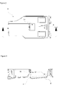
- Figure 2 - is the top view of the dispenser related to an embodiment of the present invention.
- Figure 3 - is the cross-sectional view of the dispenser taken along the line A-A in Figure 2.
- Figure 4 - is the frontal view of the dispenser related to an embodiment of the present invention.
- Figure 5 - is the cross-sectional view of the dispenser taken along the line C-C in Figure 4.
- Figure 6 - is the cross-sectional view of the dispenser taken along the line D-D in Figure 4.
- the washing machine (1) comprises a tub (2) wherein the washing process is performed; a housing (3) which is connected in fluid communication to the tub (2); a delivery line (4) which carries the water taken from the mains; a valve (5) which is disposed on the delivery line (4); a dispenser (8) which is placed into the housing (3) and which has at least one compartment (6) wherein cleaning agents such as detergent, softener, etc.
- a distributor (9) which is disposed on the housing (3), which is connected to the delivery line (4) and which provides the delivery of the water taken from the delivery line (4) into the dispenser (8); a discharge hole (10) which is arranged under the tub (2); a hose (11) which is connected to the delivery hole (10) and into which the water coming from the tub (2) fills; and a buoy (13) which is disposed into the hose (11) and which, when the level of the water in the hose (11) rises, bears against the discharge hole (10) so as to close the discharge hole (10).
- the valve (5) is opened and the mains water is taken from the mains so as to be delivered to the distributor (9) by means of the delivery line (4).
- the distributor (9) flushes the mains water into the housing (3), and the water reaching the tub (2) through the housing (3) fills into the hose (11) which extends between the discharge hole (10) and a pump (12) which sucks the water in the tub (2) to be discharged.
- the pump (12) connected to the hose (11) is operated for a time and the water filled into the tub (2) is enabled to be sucked into the hose (11) and the pump (12) is turned off a certain time after the pump (12) is operated such that the water remains in the hose (11), in other words before the water sucked from the tub (2) reaches the pump (12).
- the buoy (13) which can float on the water, rises together with the water filling into the hose (11) and bears against the discharge hole (10) so as to block the discharge hole (10).
- the washing machine (1) of the present invention comprises at least one receptacle (14) which is positioned before the compartment (6) in the flow direction of the water coming from the distributor (9) and into which the water coming from the distributor (9) fills before reaching the compartment (6), and at least one water outlet (15) which is arranged on the receptacle (14) and which enables at least some of the water filling into the receptacle (14) to be directly delivered into the housing so as to rise the buoy (13) to block the discharge hole (10).
- the receptacle (14) and the compartment (6) are disposed on the dispenser (8) one after the other in this order in the flow direction of the water.
- the sufficient amount of water to enable the buoy (13) to block the discharge hole (10) is taken into the receptacle (14) so as to be directly delivered into the tub (2) through the water outlet (15).
- the receptacle (14) is completely filled and the water overflowing from the receptacle (14) fills into the compartment (6).
- the detergent in the compartment (6) is swept by the water flowing from the receptacle (14) into the compartment (6) and is sent to the housing (3) so as to be delivered to the tub (2) by means of an opening (7) arranged on the compartment (6).
- the water flowing into the compartment (6) to sweep the detergent remains inside the tub (2), and the detergent in the compartment (6) is prevented from leaving the tub (2) before the discharge hole (10) is blocked.
- the dispenser (8) comprises a channel (16) which extends between the receptacle (14) and the compartment (6) and which, when the receptacle (14) is almost completely filled with water, allows the excess water to be sent into the compartment (6) so as to sweep the detergent in the compartment (6).
- the water outlet (15) is configured to be small enough to ensure that the amount of water flowing from the receptacle (14) into the housing (3) per unit time is less that the amount of water supplied from the distributor (9) into the receptacle (14).
- the dispenser (8) is opened by being pulled from the front side thereof out of the housing (3), and the compartment (6) is positioned such that at least a part thereof is closer to the front side of the dispenser (8) with respect to the receptacle (14).
- the compartment (6) extends from the front side of the dispenser (8) towards the rear side of the dispenser (8), and the receptacle (14) is positioned preferably at the center of the dispenser (8) so as to be distanced from the front side of the dispenser (8).
- the receptacle (14) is prevented from making the loading of detergent into the compartment (6) difficult.
- the channel (16) extends along almost the entire compartment (6).
- the channel (16) extends along almost the entire length of the side walls of the compartment (6) such that the water is carried towards the front side of the compartment (6).
- the water coming from the receptacle (14) is enabled to flow along the compartment (6) from the front side of the compartment (6) towards the opening (7) at the rear side of the compartment (6), and the detergent in the compartment (6) is efficiently swept.
- the channel (16) extends downwards in an inclined manner so as to enable the water coming from the receptacle (14) to flow therein towards the compartment (6) with the effect of gravity.
- the end of the channel (16) opening into the receptacle (14) is above the end thereof opening into the compartment (6) with respect to the floor level.
- the water entering the channel (16) through the end of the channel (16) opening into the receptacle (14) is enabled to flow towards the compartment (6) with the effect of gravity.
- This embodiment is advantageous in that the water is enabled to flow along the channel (16) in case the channel (16) is long.
- the sufficient amount of water can be carried to the parts of the compartment distanced from the receptacle (14) without requiring any additional component.
- the volume of the receptacle (14) is configured to be smaller than the volume of the compartment (6).
- the dimensions of the receptacle (14) are configured to be smaller than the dimensions of the compartment (6).
- the base area and/or the height of the receptacle (14) is/are smaller than the base area and/or the height of the compartment (6).
- the washing machine (1) comprises a control unit (17) which closes the valve (5) after the water is taken for a predetermined filling time so as to at least partially fill the receptacle (14) and which reopens the valve (5) after a predetermined waiting time elapses.
- the control unit (17) opens the valve (5) such that water is supplied to the distributor (9) for a predetermined filling time.
- Some of the water sent from the distributor (9) onto the dispenser (8) is delivered into the tub (2) through the water outlet (15) so as to carry the buoy (13) up to a level to block the discharge hole (10) while the remaining water is accumulated in the receptacle (14).
- the valve (5) is closed and kept closed for a predetermined waiting time.
- the time required for the water accumulated in the receptacle (14) to exit through the water outlet (15) to reach the tub (2) and to fill into the hose (11) is provided.
- This embodiment is particularly advantageous when the volume of the receptacle (14) is small and the flow rate of the water coming from the distributor (9) is high.
- the water coming from the distributor (9) is prevented from quickly filling the receptacle (14) and the water overflowing from the receptacle (14) is prevented from flowing into the compartment (6) before the water sent into the tub (2) through the water outlet (15) reaches the hose (11).
- the dosing process can be performed in a safer manner.
- the washing machine (1) comprises the control unit (17) which opens/closes the valve for more than one time until almost the sufficient amount of water to enable the buoy (13) to block the discharge hole (10) is taken such that the water is intermittently delivered into the receptacle (14).
- the control unit (17) enables the valve (5) to be intermittently operated (5) so as to be opened/closed at certain intervals.
- the valve (5) is opened and the receptacle (14) is filled, and then the valve (5) is closed and the receptacle (14) is waited to be entirely emptied with the discharge of the water in the receptacle (14) through the water outlet (15), and the receptacle (14) is filled and emptied for more than one time until the sufficient amount of water to enable the buoy (13) to block the discharge hole (10) is taken.
- the volume of the receptacle (14) can be smaller than the total volume of water required for being filled into the hose (11) to enable the buoy (13) to block the discharge hole (10).
- the volume occupied by the receptacle (14) in the dispenser (8) is decreased.
- the method of the present invention is suitable for operating the above-described washing machine (1) and comprises the steps of
- the method of the present invention further comprises the step (iv) of repeating the steps of (i) and (ii) for one more time before the step of (iii).
- the water delivered from the distributor (9) onto the dispenser (8) is enabled to be first sent into the receptacle (14) opening into the housing (3) to block the discharge hole (10) and to be supplied into the compartment (6) to sweep the detergent after the discharge hole (10) is blocked.
- the entire amount of water which is passed through the compartment (6) to sweep the detergent is enabled to remain inside the tub (2) and the cleaning performance of the washing machine (1) is increased.
Landscapes
- Engineering & Computer Science (AREA)
- Textile Engineering (AREA)
- Detail Structures Of Washing Machines And Dryers (AREA)
Abstract
The present invention relates to a washing machine (1) comprising a tub (2) wherein the washing process is performed; a housing (3) which is connected in fluid communication to the tub (2); a delivery line (4) which carries the water taken from the mains; a valve (5) which is disposed on the delivery line (4); a dispenser (8) which is placed into the housing (3) and which has at least one compartment (6) wherein cleaning agents such as detergent, softener, etc. are loaded; a distributor (9) which is disposed on the housing (3), which is connected to the delivery line (4) and which provides the delivery of the water taken from the delivery line (4) into the dispenser (8); a discharge hole (10) which is arranged under the tub (2); a hose (11) which is connected to the delivery hole (10) and into which the water coming from the tub (2) fills; and a buoy (13) which is disposed into the hose (11) and which, when the level of the water in the hose (11) rises, bears against the discharge hole (10) so as to close the discharge hole (10). The dispenser (8) further comprises at least one receptacle (14) which is positioned before the compartment (6) in the flow direction of the water coming from the distributor (9) and into which the water coming from the distributor (9) fills before reaching the compartment (6), said receptacle (14) having at least one water outlet (15) arranged thereon which enables at least some of the water filling into the receptacle (14) to be directly delivered into the housing (3) and into the tub (2).
Description
The present invention relates to a washing machine wherein the washing performance is improved by using the cleaning agents efficiently.
In washing machines, in general, the water taken from the mains is delivered onto the dispenser wherein the detergent is placed by means of a distributor, and the water is sent to the tub by means of a housing, wherein the dispenser is placed, to be used in the washing process. In order to ensure that the water delivered to the tub remains in the tub to be used in the washing process and then discharged from the tub after the washing process, a buoy is used, which is positioned in the hose connected to the discharge hole of the tub and which provides the opening/closing of the discharge hole. At the beginning of the washing process, a certain amount of water is taken into the tub by means of the distributor, and the buoy floats on the water filling into the hose through the discharge hole and rises with the increasing water level so as to block the discharge hole. One of the problems encountered in the washing machines comprising a buoy is that the water taken to raise the buoy at the beginning of the washing process sweeps the cleaning agents into the tub while passing through the dispenser. In this case, a significant portion of the cleaning agent carried with the water fills into the hose and is discharged after the washing process without being used in the washing process. In the state of the art washing machines, the initial water taken to raise the buoy is passed through a prewashing compartment, wherein the user loads a cleaning agent as per preference if he/she wants to perform a prewashing, which is located in the dispenser so as to be sent to the tub. Thus, the initial water is prevented from sweeping the detergent placed into the main washing compartment. However, in this case, when prewashing is desired to be performed, the detergent loaded into the prewashing compartment is swept and waste of detergent cannot be prevented. Moreover, in some washing machines, for example in washing machines wherein the liquid detergent is filled into the dispenser and stored therein, a compartment other than the main washing compartment cannot be installed due to the limitations of space.
In the state of the art European Patent Document No. EP0318069, a mains water line is disclosed, which extends between the discharge line and the flow line which enables the delivery of water into the detergent receptacle. By means of the mains water line, the water overflowing from the flow line is sent to the discharge line.
The aim of the present invention is the realization of a washing machine wherein waste of detergent is prevented.
The washing machine realized in order to attain the aim of the present invention, explicated in the first claim and the respective claims thereof, comprises a delivery line which receives the washing water; a valve which is disposed on the delivery line and which opens/closes the delivery line; a tub wherein the washing process is performed; a housing which opens into the tub; a distributor which is disposed on the ceiling of the housing and which feeds the water taken from the delivery line into the housing; a dispenser which is placed into the housing and which has at least one compartment wherein the cleaning agent is loaded; a discharge hole which is arranged on the tub; a pump which provides the discharge of the water in the tub; a hose which extends between the discharge hole and the pump; a buoy which is disposed in the hose, which can float on the water, which, when the level of the water filling into the hose increases, bears against the discharge hole so as to close the discharge hole and which, when the water in the hose is discharged by the pump, moves away from the discharge hole so as to open the discharge hole; at least one receptacle which is positioned between the distributor and the compartment in the flow direction of the water such that the water coming from the distributor fills therein before reaching the compartment and which has a water outlet allowing at least some of the water filled therein to reach the tub from the hose so as to rise the buoy. The water coming from the distributor fills into the receptacle before reaching the compartment and flows into the housing through the water outlet of the receptacle. Thus, first part of the water taken from the distributor is directly delivered to the tub without being passed through the compartment and fills into the hose so as to carry the buoy towards the discharge hole. After a sufficient amount of water is taken into the tub to enable the buoy to close the discharge hole, the water coming from the distributor is delivered to the compartment to carry the detergent into the tub. Thus, the water is enabled to reach the compartment late and to sweep the detergent in the compartment after the discharge hole is closed.
In an embodiment of the present invention, the cross-sectional area of the water outlet is small enough to ensure that the flow rate of the water leaving the receptacle through the water outlet is lower than the flow rate of the water entering the receptacle from the distributor.
In an embodiment of the present invention, the dispenser comprises at least one channel with one end opening into the receptacle and the other end into the compartment. After the sufficient amount of water is sent from the water outlet into the tub to enable the buoy to close the discharge hole, the channel provides the delivery of the water in the receptacle to the compartment. Thus, the water in the receptacle is enabled to flow into the compartment in a controlled manner and the detergent is properly swept.
In another embodiment of the present invention, the dispenser is opened by being pulled from the front side thereof out of the housing, and the compartment is positioned so as to be closer to the front side of the dispenser such that the compartment is at least partially located in front of the receptacle. Thus, the user is enabled to access the compartment without being affected by the presence of the receptacle.
In another embodiment of the present invention, the channel extends almost along the entire compartment such that the water is carried to areas of the compartment away from the receptacle. In a preferred version of this embodiment, two channels are provided at both sides of the compartment so as extend along the entire compartment. Thus, the water coming from the receptacle is enabled to homogeneously sweep the detergent in the compartment.
In an embodiment of the present invention, the end of the channel opening into the compartment is positioned at a lower level than the end thereof opening into the receptacle. Thus, the water coming from the receptacle is enabled to flow along the channel with the effect of gravity, and the water is efficiently directed.
In an embodiment of the present invention, the inner volume of the receptacle is smaller than the inner volume of the compartment. Thus, the space occupied by the receptacle in the dispenser is reduced and prevented from causing difficulty of use.
In another embodiment of the present invention, the washing machine comprises a control unit which provides the opening/closing of the valve so as to cut off the water flow before the receptacle is completely filled and to restart the water flow after the water in the receptacle is almost completely emptied. Thus, the time required for the water flowing from the receptacle into the housing to reach the hose and raise the buoy is provided. Consequently, the detergent is enabled to be dosed always after the discharge hole is closed and loss of detergent is prevented.
In another embodiment of the present invention, the washing machine comprises a control unit which opens/closes the valve at predetermined time intervals such that the water is intermittently taken into the receptacle. The control unit enables the valve to be intermittently operated until the sufficient amount of water is taken into the hose such that the buoy blocks the discharge hole. This embodiment is particularly advantageous when the volume of the receptacle is small. Thus, the water taken to close the discharge hole at the beginning of the washing process is prevented from overflowing from the receptacle.
The method used for operating the above-described washing machine comprises the steps of
- operating the valve for a predetermined operating time at the beginning of the washing process to deliver water into the receptacle,
- closing the valve and cutting off the water flow into the receptacle for a predetermined waiting time, and
- reopening the valve and sending water into the receptacle for time longer than the operating time so as to enable the water to reach the compartment.
In an embodiment of the present invention, before the step of reopening the valve and sending water into the receptacle for time longer than the operating time so as to enable the water to reach the compartment, the method repeats for at least one more time the steps of operating the valve for a predetermined operating time at the beginning of the washing process to deliver water into the receptacle, and of closing the valve and cutting off the water flow into the receptacle for a predetermined waiting time.
By means of the present invention, the water taken from the delivery line to block the discharge hole at the beginning of the washing process is enabled to fill into the receptacle to be sent to the tub before reaching the compartment, and after the discharge hole is blocked, the water taken from the delivery line is enabled to be sent to the compartment. Thus, the entire detergent loaded into the compartment is enabled to remain inside the tub.
The washing machine realized in order to attain the aim of the present invention is illustrated in the attached figures, where:
Figure 1 - is the schematic view of the washing machine related to an embodiment of the present invention.
Figure 2 - is the top view of the dispenser related to an embodiment of the present invention.
Figure 3 - is the cross-sectional view of the dispenser taken along the line A-A in Figure 2.
Figure 4 - is the frontal view of the dispenser related to an embodiment of the present invention.
Figure 5 - is the cross-sectional view of the dispenser taken along the line C-C in Figure 4.
Figure 6 - is the cross-sectional view of the dispenser taken along the line D-D in Figure 4.
The elements illustrated in the figures are numbered as follows:
- Washing machine
- Tub
- Housing
- Delivery line
- Valve
- Compartment
- Opening
- Dispenser
- Distributor
- Discharge hole
- Hose
- Pump
- Buoy
- Receptacle
- Water outlet
- Channel
- Control unit
The washing machine (1) comprises a tub (2) wherein the washing process is performed; a housing (3) which is connected in fluid communication to the tub (2); a delivery line (4) which carries the water taken from the mains; a valve (5) which is disposed on the delivery line (4); a dispenser (8) which is placed into the housing (3) and which has at least one compartment (6) wherein cleaning agents such as detergent, softener, etc. are loaded; a distributor (9) which is disposed on the housing (3), which is connected to the delivery line (4) and which provides the delivery of the water taken from the delivery line (4) into the dispenser (8); a discharge hole (10) which is arranged under the tub (2); a hose (11) which is connected to the delivery hole (10) and into which the water coming from the tub (2) fills; and a buoy (13) which is disposed into the hose (11) and which, when the level of the water in the hose (11) rises, bears against the discharge hole (10) so as to close the discharge hole (10). At the beginning of the washing process, the valve (5) is opened and the mains water is taken from the mains so as to be delivered to the distributor (9) by means of the delivery line (4). The distributor (9) flushes the mains water into the housing (3), and the water reaching the tub (2) through the housing (3) fills into the hose (11) which extends between the discharge hole (10) and a pump (12) which sucks the water in the tub (2) to be discharged. At the same time, the pump (12) connected to the hose (11) is operated for a time and the water filled into the tub (2) is enabled to be sucked into the hose (11) and the pump (12) is turned off a certain time after the pump (12) is operated such that the water remains in the hose (11), in other words before the water sucked from the tub (2) reaches the pump (12). Thus, the buoy (13), which can float on the water, rises together with the water filling into the hose (11) and bears against the discharge hole (10) so as to block the discharge hole (10).
The washing machine (1) of the present invention comprises at least one receptacle (14) which is positioned before the compartment (6) in the flow direction of the water coming from the distributor (9) and into which the water coming from the distributor (9) fills before reaching the compartment (6), and at least one water outlet (15) which is arranged on the receptacle (14) and which enables at least some of the water filling into the receptacle (14) to be directly delivered into the housing so as to rise the buoy (13) to block the discharge hole (10). The receptacle (14) and the compartment (6) are disposed on the dispenser (8) one after the other in this order in the flow direction of the water. At the beginning of the washing process, the sufficient amount of water to enable the buoy (13) to block the discharge hole (10) is taken into the receptacle (14) so as to be directly delivered into the tub (2) through the water outlet (15). After the discharge hole (10) is blocked, the receptacle (14) is completely filled and the water overflowing from the receptacle (14) fills into the compartment (6). The detergent in the compartment (6) is swept by the water flowing from the receptacle (14) into the compartment (6) and is sent to the housing (3) so as to be delivered to the tub (2) by means of an opening (7) arranged on the compartment (6). Thus, the water flowing into the compartment (6) to sweep the detergent remains inside the tub (2), and the detergent in the compartment (6) is prevented from leaving the tub (2) before the discharge hole (10) is blocked.
In an embodiment of the present invention, the dispenser (8) comprises a channel (16) which extends between the receptacle (14) and the compartment (6) and which, when the receptacle (14) is almost completely filled with water, allows the excess water to be sent into the compartment (6) so as to sweep the detergent in the compartment (6). The water outlet (15) is configured to be small enough to ensure that the amount of water flowing from the receptacle (14) into the housing (3) per unit time is less that the amount of water supplied from the distributor (9) into the receptacle (14). Thus, some of the water taken into the receptacle (14) from the distributor (9) is directly sent into the tub (2) while the remaining water is accumulated in the receptacle (14) such that the level of water in the receptacle (14) increases gradually. The end of the channel (16) opening into the receptacle (14) is above the water outlet (15) on the receptacle (14) so as to allow the water to flow into the compartment (6) when the level of water accumulated in the receptacle (14) reaches the level of the channel (16). Thus, after the discharge hole (10) is blocked by the buoy (13), the water in the receptacle (14) can be delivered into the compartment without requiring any additional component such as shutter, etc.
In another embodiment of the present invention, the dispenser (8) is opened by being pulled from the front side thereof out of the housing (3), and the compartment (6) is positioned such that at least a part thereof is closer to the front side of the dispenser (8) with respect to the receptacle (14). The compartment (6) extends from the front side of the dispenser (8) towards the rear side of the dispenser (8), and the receptacle (14) is positioned preferably at the center of the dispenser (8) so as to be distanced from the front side of the dispenser (8). Thus, the receptacle (14) is prevented from making the loading of detergent into the compartment (6) difficult.
In an embodiment of the present invention, the channel (16) extends along almost the entire compartment (6). The channel (16) extends along almost the entire length of the side walls of the compartment (6) such that the water is carried towards the front side of the compartment (6). Thus, the water coming from the receptacle (14) is enabled to flow along the compartment (6) from the front side of the compartment (6) towards the opening (7) at the rear side of the compartment (6), and the detergent in the compartment (6) is efficiently swept.
In an embodiment of the present invention, the channel (16) extends downwards in an inclined manner so as to enable the water coming from the receptacle (14) to flow therein towards the compartment (6) with the effect of gravity. The end of the channel (16) opening into the receptacle (14) is above the end thereof opening into the compartment (6) with respect to the floor level. Thus, the water entering the channel (16) through the end of the channel (16) opening into the receptacle (14) is enabled to flow towards the compartment (6) with the effect of gravity. This embodiment is advantageous in that the water is enabled to flow along the channel (16) in case the channel (16) is long. Thus, the sufficient amount of water can be carried to the parts of the compartment distanced from the receptacle (14) without requiring any additional component.
In another embodiment of the present invention, the volume of the receptacle (14) is configured to be smaller than the volume of the compartment (6). The dimensions of the receptacle (14) are configured to be smaller than the dimensions of the compartment (6). In a preferred version of this embodiment, the base area and/or the height of the receptacle (14) is/are smaller than the base area and/or the height of the compartment (6). Thus, the receptacle (14) can be positioned so as to at least partially remain in the compartment (6), and the need for leaving an additional space for positioning the receptacle (14) in the dispenser (8) is eliminated.
In another embodiment of the present invention, the washing machine (1) comprises a control unit (17) which closes the valve (5) after the water is taken for a predetermined filling time so as to at least partially fill the receptacle (14) and which reopens the valve (5) after a predetermined waiting time elapses. At the beginning of the washing process, the control unit (17) opens the valve (5) such that water is supplied to the distributor (9) for a predetermined filling time. Some of the water sent from the distributor (9) onto the dispenser (8) is delivered into the tub (2) through the water outlet (15) so as to carry the buoy (13) up to a level to block the discharge hole (10) while the remaining water is accumulated in the receptacle (14). Before the receptacle (14) is completely filled, the valve (5) is closed and kept closed for a predetermined waiting time. By keeping the valve (5) closed for the waiting time, the time required for the water accumulated in the receptacle (14) to exit through the water outlet (15) to reach the tub (2) and to fill into the hose (11) is provided. This embodiment is particularly advantageous when the volume of the receptacle (14) is small and the flow rate of the water coming from the distributor (9) is high. Thus, the water coming from the distributor (9) is prevented from quickly filling the receptacle (14) and the water overflowing from the receptacle (14) is prevented from flowing into the compartment (6) before the water sent into the tub (2) through the water outlet (15) reaches the hose (11). Thus, the dosing process can be performed in a safer manner.
In another embodiment of the present invention, the washing machine (1) comprises the control unit (17) which opens/closes the valve for more than one time until almost the sufficient amount of water to enable the buoy (13) to block the discharge hole (10) is taken such that the water is intermittently delivered into the receptacle (14). The control unit (17) enables the valve (5) to be intermittently operated (5) so as to be opened/closed at certain intervals. At the beginning of the washing process, the valve (5) is opened and the receptacle (14) is filled, and then the valve (5) is closed and the receptacle (14) is waited to be entirely emptied with the discharge of the water in the receptacle (14) through the water outlet (15), and the receptacle (14) is filled and emptied for more than one time until the sufficient amount of water to enable the buoy (13) to block the discharge hole (10) is taken. Thus, the volume of the receptacle (14) can be smaller than the total volume of water required for being filled into the hose (11) to enable the buoy (13) to block the discharge hole (10). Thus, the volume occupied by the receptacle (14) in the dispenser (8) is decreased.
The method of the present invention is suitable for operating the above-described washing machine (1) and comprises the steps of
(i) - opening the valve (5) and taking in water for a predetermined filling time to at least partially fill the receptacle (14) with water,
(ii) - closing the valve (5) and cutting off the water flow into the receptacle (14) for a predetermined waiting time,
(iii) - reopening the valve (5) and taking in water for a time longer than the filling time.
The method of the present invention further comprises the step (iv) of repeating the steps of (i) and (ii) for one more time before the step of (iii).
By means of the present invention, at the beginning of the washing process, the water delivered from the distributor (9) onto the dispenser (8) is enabled to be first sent into the receptacle (14) opening into the housing (3) to block the discharge hole (10) and to be supplied into the compartment (6) to sweep the detergent after the discharge hole (10) is blocked. Thus, the entire amount of water which is passed through the compartment (6) to sweep the detergent is enabled to remain inside the tub (2) and the cleaning performance of the washing machine (1) is increased.
Claims (10)
- A washing machine (1) comprising a tub (2) wherein the washing process is performed; a housing (3) which is connected in fluid communication to the tub (2); a delivery line (4) which carries the water taken from the mains; a valve (5) which is disposed on the delivery line (4); a dispenser (8) which is placed into the housing (3) and which has at least one compartment (6) wherein cleaning agents such as detergent, softener, etc. are loaded; a distributor (9) which is disposed on the housing (3), which is connected to the delivery line (4) and which provides the delivery of the water taken from the delivery line (4) into the dispenser (8); a discharge hole (10) which is arranged under the tub (2); a hose (11) which is connected to the delivery hole (10) and into which the water coming from the tub (2) fills; and a buoy (13) which is disposed into the hose (11) and which, when the level of the water in the hose (11) rises, bears against the discharge hole (10) so as to close the discharge hole (10), characterized by at least one receptacle (14) which is positioned before the compartment (6) in the flow direction of the water coming from the distributor (9) and into which the water coming from the distributor (9) fills before reaching the compartment (6), and at least one water outlet (15) which is arranged on the receptacle (14) and which enables at least some of the water filling into the receptacle (14) to be directly delivered into the housing so as to rise the buoy (13) to block the discharge hole (10).
- A washing machine (1) as in Claim 1, characterized by a channel (16) which extends between the receptacle (14) and the compartment (6) and which, when the receptacle (14) is almost completely filled with water, allows the excess water to be sent into the compartment (6) so as to sweep the detergent in the compartment (6).
- A washing machine (1) as in Claim 1 or Claim 2, characterized by the dispenser (8) which is pulled from the front side thereof out of the housing (3), and by the compartment (6) which is positioned such that at least a part thereof is closer to the front side of the dispenser (8) with respect to the receptacle (14).
- A washing machine (1) as in Claim 2 or Claim 3, characterized by the channel (16) which extends almost along the entire compartment (6).
- A washing machine (1) as in any one of the Claim 2 to 4, characterized by the channel (16) which extends downwards in an inclined manner so as to enable the water coming from the receptacle (14) to flow therein towards the compartment (6) with the effect of gravity.
- A washing machine (1) as in any one of the above claims, characterized by the receptacle (14) of which the volume is smaller than the volume of the compartment (6).
- A washing machine (1) as in any one of the above claims, characterized by a control unit (17) which closes the valve (5) after the water is taken for a predetermined filling time so as to at least partially fill the receptacle (14) and which reopens the valve (5) after a predetermined waiting time elapses.
- A washing machine (1) as in Claim 7, characterized by the control unit (17) which opens/closes the valve for more than one time until the sufficient amount of water to enable the buoy (13) to block the discharge hole (10) is taken such that the water is intermittently delivered into the receptacle (14).
- A method for operating a washing machine (1) as in any one of the above claims, comprising the steps of(i) - opening the valve (5) and taking in water for a predetermined filling time to at least partially fill the receptacle (14) with water,(ii) - closing the valve (5) and cutting off the water flow into the receptacle (14) for a predetermined waiting time,(iii) - reopening the valve (5) and taking in water for a time longer than the filling time.
- A method for operating a washing machine (1) as in any one of the above claims, comprising the step of(iv) - repeating the steps of (i) and (ii) for one more time before the step of (iii).
Applications Claiming Priority (2)
| Application Number | Priority Date | Filing Date | Title |
|---|---|---|---|
| TR2018/12462 | 2018-08-31 | ||
| TR201812462 | 2018-08-31 |
Publications (1)
| Publication Number | Publication Date |
|---|---|
| WO2020043356A1 true WO2020043356A1 (en) | 2020-03-05 |
Family
ID=67262275
Family Applications (1)
| Application Number | Title | Priority Date | Filing Date |
|---|---|---|---|
| PCT/EP2019/067444 Ceased WO2020043356A1 (en) | 2018-08-31 | 2019-06-28 | A washing machine with improved washing performance and the control method of the same |
Country Status (1)
| Country | Link |
|---|---|
| WO (1) | WO2020043356A1 (en) |
Citations (3)
| Publication number | Priority date | Publication date | Assignee | Title |
|---|---|---|---|---|
| DE3822392A1 (en) * | 1987-10-06 | 1989-04-20 | Bosch Siemens Hausgeraete | Washing machine with at least one fresh-water feed conduit |
| EP0318069A1 (en) | 1987-10-09 | 1989-05-31 | Bauknecht Hausgeräte GmbH | Washing machine with means for avoiding detergent wastage |
| DE102016205608B3 (en) * | 2016-04-05 | 2017-05-11 | BSH Hausgeräte GmbH | Laundry care device with a controller |
-
2019
- 2019-06-28 WO PCT/EP2019/067444 patent/WO2020043356A1/en not_active Ceased
Patent Citations (3)
| Publication number | Priority date | Publication date | Assignee | Title |
|---|---|---|---|---|
| DE3822392A1 (en) * | 1987-10-06 | 1989-04-20 | Bosch Siemens Hausgeraete | Washing machine with at least one fresh-water feed conduit |
| EP0318069A1 (en) | 1987-10-09 | 1989-05-31 | Bauknecht Hausgeräte GmbH | Washing machine with means for avoiding detergent wastage |
| DE102016205608B3 (en) * | 2016-04-05 | 2017-05-11 | BSH Hausgeräte GmbH | Laundry care device with a controller |
Similar Documents
| Publication | Publication Date | Title |
|---|---|---|
| EP2142697B1 (en) | Laundry washing machine | |
| US8246756B2 (en) | Method for automatically flushing a bulk dispensing system in a cleaning appliance | |
| US9334602B2 (en) | Water-carrying household appliance having an automatic dosing system, and method for automatic dosing | |
| CN115381366B (en) | dishwasher | |
| DK3019066T3 (en) | DISHWASHER, INCLUDING A CLEANING SYSTEM FOR A LIQUID / GEL-DETERGENT DOSING UNIT AND A CONTAINER UNIT | |
| EP3041982B1 (en) | A washer comprising an automatic dosing unit | |
| CN112739866A (en) | Method and apparatus for cleaning laundry | |
| AU2017281507B2 (en) | Operating method of a laundry washing machine and laundry washing machine implementing such method | |
| EP3673107A1 (en) | A liquid detergent dosing unit for washing machines | |
| KR20220061888A (en) | Washing machine and method for operating such a washing machine | |
| WO2019068698A1 (en) | A detergent dosing system for washing machines and a detergent saving method | |
| KR20050118896A (en) | Drain pump & drum type washing machine having the same | |
| EP3234253B1 (en) | Laundry washing machine | |
| CN110840348A (en) | Control method of dish-washing machine and dish-washing machine | |
| JP4244491B2 (en) | Washing machine | |
| JP3540798B2 (en) | Fully automatic washing machine | |
| WO2015051826A1 (en) | Improved three-way valve suitable for use in a dishwasher | |
| CN107620197A (en) | A kind of washing machine with automatic addition detergent or washing assisant device | |
| KR20220026822A (en) | Dishwasher | |
| JP2026059693A (en) | washing machine | |
| JP2024137145A (en) | washing machine | |
| US3897806A (en) | Liquid flow diversion arrangement | |
| CN120776552A (en) | Throwing device and clothes treatment equipment | |
| KR100557757B1 (en) | Drum Washing Machine | |
| KR0120656Y1 (en) | Water-supplying device of a washing machine |
Legal Events
| Date | Code | Title | Description |
|---|---|---|---|
| 121 | Ep: the epo has been informed by wipo that ep was designated in this application |
Ref document number: 19739529 Country of ref document: EP Kind code of ref document: A1 |
|
| NENP | Non-entry into the national phase |
Ref country code: DE |
|
| 122 | Ep: pct application non-entry in european phase |
Ref document number: 19739529 Country of ref document: EP Kind code of ref document: A1 |