WO2020040154A1 - プリプレグ、プリプレグテープおよび繊維強化複合材料の製造方法、プリプレグ製造装置 - Google Patents
プリプレグ、プリプレグテープおよび繊維強化複合材料の製造方法、プリプレグ製造装置 Download PDFInfo
- Publication number
- WO2020040154A1 WO2020040154A1 PCT/JP2019/032496 JP2019032496W WO2020040154A1 WO 2020040154 A1 WO2020040154 A1 WO 2020040154A1 JP 2019032496 W JP2019032496 W JP 2019032496W WO 2020040154 A1 WO2020040154 A1 WO 2020040154A1
- Authority
- WO
- WIPO (PCT)
- Prior art keywords
- fiber sheet
- matrix resin
- reinforcing fiber
- prepreg
- sheet
- Prior art date
- Legal status (The legal status is an assumption and is not a legal conclusion. Google has not performed a legal analysis and makes no representation as to the accuracy of the status listed.)
- Ceased
Links
Images


Classifications
-
- B—PERFORMING OPERATIONS; TRANSPORTING
- B29—WORKING OF PLASTICS; WORKING OF SUBSTANCES IN A PLASTIC STATE IN GENERAL
- B29B—PREPARATION OR PRETREATMENT OF THE MATERIAL TO BE SHAPED; MAKING GRANULES OR PREFORMS; RECOVERY OF PLASTICS OR OTHER CONSTITUENTS OF WASTE MATERIAL CONTAINING PLASTICS
- B29B15/00—Pretreatment of the material to be shaped, not covered by groups B29B7/00 - B29B13/00
- B29B15/08—Pretreatment of the material to be shaped, not covered by groups B29B7/00 - B29B13/00 of reinforcements or fillers
- B29B15/10—Coating or impregnating independently of the moulding or shaping step
- B29B15/12—Coating or impregnating independently of the moulding or shaping step of reinforcements of indefinite length
- B29B15/122—Coating or impregnating independently of the moulding or shaping step of reinforcements of indefinite length with a matrix in liquid form, e.g. as melt, solution or latex
- B29B15/125—Coating or impregnating independently of the moulding or shaping step of reinforcements of indefinite length with a matrix in liquid form, e.g. as melt, solution or latex by dipping
-
- B—PERFORMING OPERATIONS; TRANSPORTING
- B29—WORKING OF PLASTICS; WORKING OF SUBSTANCES IN A PLASTIC STATE IN GENERAL
- B29B—PREPARATION OR PRETREATMENT OF THE MATERIAL TO BE SHAPED; MAKING GRANULES OR PREFORMS; RECOVERY OF PLASTICS OR OTHER CONSTITUENTS OF WASTE MATERIAL CONTAINING PLASTICS
- B29B11/00—Making preforms
- B29B11/14—Making preforms characterised by structure or composition
- B29B11/16—Making preforms characterised by structure or composition comprising fillers or reinforcement
-
- B—PERFORMING OPERATIONS; TRANSPORTING
- B29—WORKING OF PLASTICS; WORKING OF SUBSTANCES IN A PLASTIC STATE IN GENERAL
- B29K—INDEXING SCHEME ASSOCIATED WITH SUBCLASSES B29B, B29C OR B29D, RELATING TO MOULDING MATERIALS OR TO MATERIALS FOR MOULDS, REINFORCEMENTS, FILLERS OR PREFORMED PARTS, e.g. INSERTS
- B29K2063/00—Use of EP, i.e. epoxy resins or derivatives thereof, as moulding material
-
- B—PERFORMING OPERATIONS; TRANSPORTING
- B29—WORKING OF PLASTICS; WORKING OF SUBSTANCES IN A PLASTIC STATE IN GENERAL
- B29K—INDEXING SCHEME ASSOCIATED WITH SUBCLASSES B29B, B29C OR B29D, RELATING TO MOULDING MATERIALS OR TO MATERIALS FOR MOULDS, REINFORCEMENTS, FILLERS OR PREFORMED PARTS, e.g. INSERTS
- B29K2307/00—Use of elements other than metals as reinforcement
- B29K2307/04—Carbon
Definitions
- the present invention relates to a method for producing a prepreg, a prepreg tape and a fiber-reinforced composite material, and a prepreg production apparatus, and more particularly to a method and an apparatus for uniformly impregnating a reinforcing fiber sheet with a matrix resin.
- Fiber reinforced composite material which is a matrix resin containing thermoplastic resin and thermosetting resin reinforced with reinforcing fibers, is a material for aviation and space, automotive material, industrial material, pressure vessel, building material, housing, medical equipment. It is used in various fields such as applications and sports. Particularly when high mechanical properties and lightness are required, carbon fiber reinforced composite materials (CFRP) are widely and suitably used. On the other hand, when cost is prioritized over mechanical properties and light weight, a glass fiber reinforced composite material (GFRP) may be used. In the FRP, a reinforcing fiber bundle is impregnated with a matrix resin to obtain an intermediate base material, which is laminated and molded, and when a thermosetting resin is used, is thermoset to produce a member made of FRP.
- CFRP carbon fiber reinforced composite materials
- GFRP glass fiber reinforced composite material
- the two-dimensional sheet-like material is more often used as an intermediate substrate of FRP than a one-dimensional strand or roving-like material when producing a member. It is widely used from the viewpoint of lamination efficiency and moldability.
- narrow-width tape-like intermediate substrates are preferably used here.
- the narrow tape-shaped intermediate substrate can be obtained by slicing a wide sheet-shaped intermediate substrate at a desired width, or by directly impregnating a narrow reinforcing fiber sheet with a matrix resin.
- a prepreg obtained by impregnating a reinforcing fiber sheet with a matrix resin is widely used.
- the reinforcing fiber sheet used for the prepreg include a UD base material in which reinforcing fibers are arranged in one direction and in a sheet form, and a reinforcing fiber fabric which is a woven fabric arranged in multiple directions. Particularly when the mechanical properties are prioritized, the UD base material is often used.
- the hot melt method which is one of the prepreg manufacturing methods, involves melting a matrix resin, coating it on a release sheet, and sandwiching this on the upper and lower surfaces of a reinforcing fiber sheet to produce a laminated structure. This impregnates the inside of the reinforcing fiber sheet with the matrix resin. This method has a problem that the number of steps is large, the production speed cannot be increased, and the cost is high.
- Patent Document 2 a method for simultaneously forming a coating film on both sides of a sheet material is described in Patent Document 2.
- the sheet material is passed through a web guide. After that, coating is performed with a pipe type doctor.
- Patent Literature 3 Patent Literature 4, etc.
- Patent Document 3 a tape-like reinforcing fiber is passed through a crosshead (FIG. 2 of Patent Document 3), and a resin is applied to a tape-like reinforcing fiber bundle immediately before a linear die portion in the crosshead.
- Patent Document 4 discloses that a plurality of band-shaped reinforcing fiber bundles are separately introduced into a die filled with a molten thermoplastic resin, opened, impregnated, and laminated by a fixed guide (for example, a squeeze bar). It is described that the sheet-shaped prepreg is pulled out from a die.
- Patent Document 1 can only produce strands or rovings, and cannot be applied to the production of sheet-like prepregs that are the subject of the present invention.
- a fluid of a thermoplastic resin is applied to the strand or the side surface of the roving-like reinforcing fiber bundle to generate turbulent flow positively in the conical flow path. It is considered that this is intended to partially disturb the arrangement of the reinforcing fiber bundle and allow the matrix resin to flow, but when this concept is applied to the reinforcing fiber sheet, the arrangement of the reinforcing fibers is disturbed, and the quality of the prepreg is reduced. It is thought that not only does the FRP decrease, but also the mechanical properties of the FRP decrease.
- the sheet-like material in Patent Document 2 is a film, cloth, paper, foil, a punching plate, a net-like sheet material, and the like, and the reinforcing fiber sheet that is the object of the present invention is not intended. If the technique of Patent Literature 2 is applied to a reinforcing fiber sheet made of carbon fibers, it is considered that fluff is generated by rubbing with a web guide, and the running of the reinforcing fiber sheet becomes difficult. Further, the technique of Patent Document 2 is coating of a resin, and impregnation is not intended.
- An object of the present invention is to reduce the generation of fluff in the prepreg production method, to enable continuous production without clogging of fluff, and to impregnate the reinforcing fiber sheet with a matrix resin efficiently, thereby increasing the production speed. It is another object of the present invention to provide a method and an apparatus for producing a prepreg, which is possible, and further suppresses the obtained reinforcing fiber sheet from being broken or the like and has a uniform basis weight.
- the method for producing a prepreg of the present invention that solves the above-described problem is to pass the reinforcing fiber sheet substantially vertically downward inside the application section where the matrix resin is stored, and to apply the matrix resin to the reinforcing fiber sheet.
- a step of obtaining a matrix resin-impregnated reinforced fiber sheet a method for producing a prepreg including a step of heating the matrix resin-impregnated reinforced fiber sheet in a non-contact manner,
- the application unit includes a liquid reservoir and a constricted portion that are communicated with each other, the liquid reservoir has a portion having a continuously decreasing cross-sectional area along a running direction of the reinforcing fiber sheet, and the constricted portion has a slit shape.
- the constriction has a slit-shaped cross-section and a cross-section smaller than the upper surface of the liquid reservoir, and is subjected to additional impregnation from the outlet of the application part.
- a liquid reservoir having a portion in which the matrix resin is stored and having a cross-sectional area continuously decreasing vertically downward; a constricted portion having a slit-shaped outlet communicating with a lower end of the liquid reservoir;
- a method for producing a prepreg tape of the present invention is characterized in that the prepreg obtained by the above-described method for producing a prepreg is slit.
- the method for producing a fiber-reinforced composite material of the present invention is characterized in that the prepreg obtained by the above-described method for producing a prepreg or the prepreg tape obtained by the above-described method for producing a prepreg tape is cured.
- FIG. 1 is a schematic cross-sectional view illustrating a prepreg manufacturing method according to an embodiment of a first manufacturing method of the present invention. It is a schematic cross section showing the manufacturing method of the prepreg concerning the embodiment of the 2nd manufacturing method of the present invention.
- FIG. 2 is a detailed transverse cross-sectional view in which the application section and the additional impregnation device 19 in FIG. 1 are enlarged.
- FIG. 2A is a detailed cross-sectional view when a release sheet 3 is used in another embodiment different from FIG. 2A. It is a schematic cross section showing the manufacturing method of the prepreg concerning the embodiment of the 3rd manufacturing method of the present invention.
- FIG. 1 is a schematic cross-sectional view illustrating a prepreg manufacturing method according to an embodiment of a first manufacturing method of the present invention. It is a schematic cross section showing the manufacturing method of the prepreg concerning the embodiment of the 2nd manufacturing method of the present invention.
- FIG. 2 is a detailed transverse cross-sectional view in
- FIG. 2 is an enlarged detailed cross-sectional view of a coating section in FIG. 1.
- FIG. 5 is a bottom view of the application unit in FIG. 4 when viewed from the direction of A in FIG. 4.
- FIG. 5 is a cross-sectional view illustrating a structure inside the application section when the application section in FIG. 4 is viewed from a direction B in FIG. 4. It is sectional drawing showing the flow of the matrix resin 2 in the clearance gap 26 in FIG. 6a.
- FIG. 4 is a detailed cross-sectional view in which a coating section of FIG. 3 is enlarged.
- FIG. 4 is a detailed cross-sectional view of the reinforcing fiber sheet 1a that contacts a bar 35 inside the liquid reservoir 22.
- FIG. 14 is a detailed cross-sectional view of a bar 35 of another embodiment. It is a figure showing an example of installation of a width regulation mechanism.
- FIG. 8 is a detailed cross-sectional view illustrating a structure inside the application section when the application section in FIG. 7 is viewed from a direction B in the figure.
- FIG. 12 is a detailed cross-sectional view illustrating an internal structure of a coating section 41 of an embodiment different from FIG. 11. It is a figure showing an example which provides width control members at both ends of a bar. It is a figure which shows the width
- FIG. 13 is a detailed cross-sectional view illustrating an internal structure of a coating section 42 of an embodiment different from FIG. 11.
- FIG. 11 is a detailed cross-sectional view illustrating an internal structure of a coating section 42 of an embodiment different from FIG. 11.
- FIG. 5 is a detailed cross-sectional view of a coating unit 20b according to another embodiment different from FIG. 4.
- FIG. 17 is a detailed cross-sectional view of a coating unit 20c according to another embodiment different from FIG. 16.
- FIG. 17 is a detailed cross-sectional view of a coating unit 20d according to another embodiment different from FIG. 16.
- FIG. 17 is a detailed cross-sectional view of a coating section 20e of another embodiment different from FIG.
- FIG. 4 is a detailed cross-sectional view of a coating unit 30 according to an embodiment different from the present invention.
- It is a schematic diagram showing an example of an embodiment of a prepreg manufacturing process using the first manufacturing method of the present invention. It is the schematic of the example of another prepreg manufacturing process using the 2nd manufacturing method of this invention.
- the present invention discloses three new prepreg manufacturing methods. These production methods obtain a matrix resin-impregnated reinforced fiber sheet in which the matrix resin is applied to the reinforced fiber sheet by passing the reinforced fiber sheet substantially vertically downward inside the application portion in which the matrix resin is stored. In common. In this production method, the following three production methods are used in order to further improve the degree of impregnation of the obtained prepreg.
- the coating device 100 is provided between the transport rolls 13 and 14, which are traveling mechanisms for traveling the reinforcing fiber sheet 1a substantially vertically downward Z, and is a coating mechanism in which the matrix resin 2 is stored.
- An application unit 20 is provided. Further, before and after the coating apparatus 100, a plurality of creels 11 for unwinding the reinforcing fibers 1 and a reinforcing fiber sheet 1a in which the unwound reinforcing fibers 1 are arranged in one direction (in FIG. 1, arranged in the depth direction of the paper). And a winding device 17 for the prepreg 1c.
- the coating device 100 is provided with a matrix resin supply device (not shown).
- an additional impregnation device 19 is provided between the coating unit 20 and the transport roll 14.
- this is a non-contact heating device.
- the release sheet 3 can be provided to the prepreg 1c additionally impregnated by the non-contact heating device. In FIG. 1, the release sheet 3 is provided on only one side, but may be provided on both sides of the prepreg 1c.
- the coating device 100 is provided between the transport rolls 13 and 14, which are traveling mechanisms for traveling the reinforcing fiber sheet 1a substantially vertically downward Z, and is a coating mechanism in which the matrix resin 2 is stored.
- An application unit 20 is provided. Further, before and after the coating apparatus 100, a plurality of creels 11 for unwinding the reinforcing fibers 1 and a reinforcing fiber sheet 1a in which the unwound reinforcing fibers 1 are arranged in one direction (in FIG. 2, arranged in the depth direction of the paper). And a winding device 17 for the prepreg 1c.
- the coating device 100 is provided with a matrix resin supply device (not shown).
- an additional impregnation device 19 is provided between the coating unit 20 and the transport roll 14.
- the release sheet 3 may be provided between the coating unit 20 and the transport roll 14.
- the release sheet 3 may be provided between the coating unit 20 and the transport roll 14.
- the release sheet 3 may be provided between the coating unit 20 and the transport roll 14.
- the release sheet 3 may be provided between the coating unit 20 and the transport roll 14.
- a release sheet supply device 18 that supplies the release sheet 3 to both surfaces of the matrix resin-impregnated reinforced fiber sheet 1b obtained immediately below the application section 20 can be provided.
- the release sheet 3 may be introduced and applied using the transport rolls 15 and 16.
- FIG. 2A shows a state in which the release sheet 3 is applied from both sides of the matrix resin-impregnated reinforced fiber sheet 1b, but the release sheet 3 to be applied may be one side.
- a release sheet heating device 18a for heating the release sheet 3 may be provided.
- FIG. 1 shows a state in which the release sheet heating device 18a is heated from both sides of the release sheet 3, it may be only one side.
- FIG. 2A shows a case where a non-contact heating device is used for the release sheet 3 as the release sheet heating device 18a, but a contact type heating device may be used.
- the coating apparatus 101 is provided between transport rolls 13 and 14, which are traveling mechanisms for traveling the reinforcing fiber sheet 1a substantially vertically downward Z, and the matrix resin 2 is stored therein.
- An application unit 40 as an application mechanism is provided.
- a bar group 35 35a, 35b, 35c) extending in the depth direction of the paper is provided inside the coating unit 40.
- a plurality of creels 11 for unwinding the reinforcing fibers 1 and a reinforcing fiber sheet 1a in which the unwound reinforcing fibers 1 are arranged in one direction in FIG. 3, arranged in the depth direction of the drawing).
- the coating device 100 is provided with a matrix resin supply device (not shown). Further, if necessary, a release sheet supply device 18 for supplying the release sheet 3 can be provided. In FIG. 3, the release sheet 3 is provided on only one side, but may be provided on both sides of the prepreg 1c.
- examples of the reinforcing fiber 1 include carbon fiber, glass fiber, metal fiber, metal oxide fiber, metal nitride fiber, organic fiber (aramid fiber, polybenzoxazole fiber, polyvinyl alcohol fiber, polyethylene fiber, etc.). However, it is preferable to use carbon fibers from the viewpoint of the mechanical properties and light weight of the FRP.
- a UD base material arranged in one direction and a reinforcing fiber fabric as a woven fabric are exemplified.
- the unidirectionally arranged UD base material as the reinforcing fiber sheet 1a refers to one in which a plurality of reinforcing fibers are arranged on a surface in one direction, and the plurality of reinforcing fibers are not necessarily intertwined with each other and are integrally formed. It is not necessary to make it. That is, according to the production method of the present invention, after application of the matrix resin, the matrix resin is obtained as a sheet impregnated with the matrix resin. Therefore, the state in which the reinforcing fibers are arranged is referred to as a reinforcing fiber sheet for convenience.
- the thickness and width of the reinforcing fiber sheet are not particularly limited, and can be appropriately selected depending on the purpose and application.
- the tow In the case of carbon fibers, usually, about 1,000 to 1,000,000 single fibers collected in a tape form are called "tow", and the tow is arranged to form a reinforcing fiber sheet. Although it can be obtained, tows may be laminated in the thickness direction.
- the reinforcing fiber sheet preferably has an aspect ratio defined by the width / thickness of 10 or more because it is easy to handle.
- one tape-shaped “toe” is also understood as one form of the reinforcing fiber sheet.
- a known method can be used for forming the reinforcing fiber sheet 1a, and there is no particular limitation.
- a reinforcing fiber bundle in which single fibers are arranged in advance is formed, and the reinforcing fiber bundle is further arranged to strengthen the reinforcing fiber sheet.
- Forming the fiber sheet 1a is preferable from the viewpoint of process efficiency and uniform arrangement. For example, in carbon fiber, as described above, a tape-shaped reinforcing fiber bundle “toe” is wound around a bobbin, and a tape-shaped reinforcing fiber bundle drawn out from this is arranged to strengthen the UD base material. A fiber sheet can be obtained.
- the reinforcing fiber bundles drawn out from the creeled bobbin in an orderly manner, and to have an arrangement mechanism for eliminating undesirable overlapping and folding of the reinforcing fiber bundles in the reinforcing fiber sheet and gaps between the reinforcing fiber bundles.
- the reinforcing fiber arranging mechanism a known roller or comb-type arranging device can be used. It is also useful to stack a plurality of pre-arranged reinforcing fiber sheets from the viewpoint of reducing the gap between the reinforcing fibers.
- the creel is preferably provided with a tension control mechanism when drawing out the reinforcing fibers.
- the tension control mechanism a known mechanism can be used, and a brake mechanism or the like can be used. The tension can also be controlled by adjusting the thread guide.
- the reinforcing fiber fabric as the reinforcing fiber sheet of the present invention is a sheet in which reinforcing fibers are arranged in a multiaxial manner or randomly arranged to form a sheet.
- Specific examples thereof include those in which reinforcing fibers are two-dimensionally arranged in a multiaxial manner, and those in which reinforcing fibers such as a nonwoven fabric, a mat, and paper are randomly oriented, in addition to a woven fabric or a knitted fabric.
- the reinforcing fibers can be formed into a sheet using a method such as binder application, entanglement, welding, or fusion.
- a non-crimp woven fabric, a bias structure, an entangled woven fabric, a multiaxial woven fabric, a multiple woven fabric, or the like can be used in addition to the plain woven fabric, twill fabric, and satin woven fabric.
- the woven fabric combining the bias structure and the UD substrate not only suppresses the deformation of the woven fabric due to the tension in the coating / impregnation process due to the UD structure, but also has the pseudo-isotropy due to the bias structure, which is a preferable form.
- the multi-layer fabric has an advantage that the structure / characteristics of the fabric upper / lower surface and the inside of the fabric can be individually designed. In the case of knitted fabrics, warp knitting is preferred in view of the form stability in the coating / impregnation step, but a blade which is a tubular knitted fabric can also be used.
- the thickness of the reinforcing fiber fabric is not particularly limited as long as the effects of the present invention can be obtained, and may be determined in consideration of the required FRP performance and the stability of the coating process. In consideration of the permeability of the stenosis, it is preferably 1 mm or less, more preferably 0.3 mm or less.
- Reinforced fiber fabrics are available from the market and can be made suitable for the purpose.
- An example is described below.
- Examples of the woven fabric include “Toreca (registered trademark)” cloth C06142, C06347B, and C05642 manufactured by Toray Industries, Inc., and “HexForce (registered trademark)” Fabrics and “PrimeTex (registered trademark) 84, G0801 manufactured by HEXCEL.
- G108 which is a hybrid fabric of carbon fiber and glass fiber, such as GB201, G0986, G0926, etc. of carbon fiber and glass fiber. , G0874, G0973, 43743, etc., and 20796 and 21263 which are aramid fiber fabrics, and 610 and 593 which are Quartz fabrics.
- nonwoven fabrics, mats, and papers examples include “Torayca (registered trademark)” mats B030, B050, and BV03 manufactured by Toray Industries, Inc., and CEO-030 and CBP-030 of “Carbolite (registered trademark)” manufactured by Olivet. ZX-020 and the like.
- the method of smoothing is not particularly limited, and examples thereof include a method of physically pressing with a facing roll or the like, and a method of moving a reinforcing fiber using an air flow.
- the physical pressing method is preferred because it is simple and does not easily disturb the arrangement of the reinforcing fibers. More specifically, calendering or the like can be used.
- the method using an air flow is preferable because it not only causes less abrasion but also has the effect of widening the reinforcing fiber sheet.
- the reinforcing fiber sheet it is also preferable to guide the reinforcing fiber sheet to the liquid pool after widening the reinforcing fiber sheet from the viewpoint of efficiently producing a thin prepreg.
- the widening processing method there is no particular limitation on the widening processing method, and examples thereof include a method of mechanically applying vibration and a method of expanding the reinforcing fiber bundle by an air flow.
- a method of mechanically applying vibration there is a method of bringing a reinforcing fiber sheet into contact with a vibrating roll as described in, for example, JP-A-2015-22799.
- the vibration direction when the traveling direction of the reinforcing fiber sheet is the X axis, it is preferable to apply vibrations in the Y axis direction (horizontal direction) and the Z axis direction (vertical direction). It is also preferable to use them in combination. It is preferable that a plurality of projections are provided on the surface of the vibrating roll, because the abrasion of the reinforcing fibers by the roll can be suppressed.
- a method using an air flow see, for example, SEN-I GAKKAISHI, vol. 64, P-262-267 (2008). The described method can be used.
- the reinforcing fiber sheet is heated and then guided to the liquid pool portion, because the temperature decrease of the matrix resin can be suppressed and the viscosity uniformity of the matrix resin can be improved.
- the reinforcing fiber sheet is preferably heated to a temperature close to the matrix resin temperature.
- heating means include air heating, infrared heating, far infrared heating, laser heating, contact heating, and heating medium heating (such as steam). Means can be used. Above all, infrared heating is preferable because the apparatus is simple and the reinforcing fiber sheet can be directly heated, so that it can be efficiently heated to a desired temperature even at a high running speed.
- the matrix resin used in the present invention can be used as a resin composition containing various resins and particles described below, a curing agent, and various additives.
- the prepreg obtained by the present invention is in a state in which the matrix resin is impregnated in the reinforcing fiber sheet, and can be laminated and molded as a sheet-shaped prepreg to obtain a member made of FRP.
- the degree of impregnation can be controlled by the design of the application section and the additional impregnation after application.
- the matrix resin can be appropriately selected depending on the application, but it is common to use a thermoplastic resin or a thermosetting resin.
- the matrix resin may be a molten resin heated and melted or a matrix resin at room temperature. Further, a solution or a varnish formed using a solvent may be used.
- a resin generally used for FRP such as a thermoplastic resin, a thermosetting resin, and a photocurable resin can be used. Further, these may be used as they are if they are liquids at room temperature, or may be used as solids or viscous liquids at room temperature to reduce the viscosity by heating, or may be used as a melt by melting, or a solvent. May be used as a solution or varnish.
- the thermoplastic resin is selected from a carbon-carbon bond, an amide bond, an imide bond, an ester bond, an ether bond, a carbonate bond, a urethane bond, a urea bond, a thioether bond, a sulfone bond, an imidazole bond, and a carbonyl bond in the main chain.
- a polymer having a bond can be used.
- PPS, PES, PI, PEI, PSU, PEEK, PEKK, PAEK, and the like are suitable.
- polyolefins such as polypropylene (PP), PA, polyester, PPS, and the like are preferable in order to increase molding efficiency.
- PP polypropylene
- PA polypropylene
- polyester polypropylene
- PPS polypropylene
- these may be polymers or oligomers or monomers for low viscosity and low temperature coating. Of course, these may be copolymerized depending on the purpose, or may be used as a polymer blend alloy by mixing various types.
- thermosetting resin examples include an epoxy resin, a maleimide resin, a polyimide resin, a resin having an acetylene terminal, a resin having a vinyl terminal, a resin having an allyl terminal, a resin having a nadic acid terminal, and a resin having a cyanate ester terminal.
- an epoxy resin a maleimide resin, a polyimide resin, a resin having an acetylene terminal, a resin having a vinyl terminal, a resin having an allyl terminal, a resin having a nadic acid terminal, and a resin having a cyanate ester terminal.
- thermosetting resin suitable for the present invention an epoxy resin is preferably used because of its excellent heat resistance, chemical resistance, and mechanical properties.
- an epoxy resin using an amine, a phenol, or a compound having a carbon-carbon double bond as a precursor is preferable.
- an epoxy resin having an amine as a precursor various isomers of tetraglycidyldiaminodiphenylmethane, triglycidyl-p-aminophenol, triglycidyl-m-aminophenol, and triglycidylaminocresol, and phenols are used as precursors.
- the epoxy resin include, but are not limited to, alicyclic epoxy resins. Brominated epoxy resins obtained by brominating these epoxy resins are also used.
- An epoxy resin having an aromatic amine represented by tetraglycidyldiaminodiphenylmethane as a precursor has a good heat resistance and a good adhesion to a reinforcing fiber, and is most suitable for the present invention.
- Thermosetting resin is preferably used in combination with a curing agent.
- the curing agent may be a compound having an active group capable of reacting with an epoxy group.
- a compound having an amino group, an acid anhydride group, or an azide group is suitable.
- dicyandiamide, various isomers of diaminodiphenylsulfone, and aminobenzoic acid esters are suitable. More specifically, dicyandiamide is preferably used because of its excellent prepreg preservability. Further, various isomers of diaminodiphenyl sulfone are most suitable for the present invention because they give cured products having good heat resistance.
- trimethylene glycol di-p-aminobenzoate and neopentyl glycol di-p-aminobenzoate are preferably used.
- the heat resistance is lower than that of diaminodiphenyl sulfone, the tensile strength is lower. Because it is excellent, it is selected and used according to the application. It is also possible to use a curing catalyst if necessary. From the viewpoint of improving the pot life of the matrix resin, it is also possible to use a complexing agent capable of forming a complex with a curing agent or a curing catalyst.
- thermoplastic resin mixed with a thermosetting resin it is also preferable to use a thermoplastic resin mixed with a thermosetting resin.
- a mixture of a thermosetting resin and a thermoplastic resin gives better results than using the thermosetting resin alone. This is because while thermosetting resins generally have the disadvantage of being brittle, low-pressure molding with an autoclave is possible, whereas thermoplastic resins have the advantage of being generally tough, but low-pressure molding with an autoclave is difficult. This is because they exhibit a trade-off characteristic, that is, they can be used in combination to balance physical properties and moldability.
- the present invention it is preferable to use a matrix resin containing polymer particles since the toughness and impact resistance of the obtained CFRP can be improved.
- the glass transition temperature (Tg) or the melting point (Tm) of the polymer particles be higher than the matrix resin temperature by 20 ° C. or more, because the shape of the polymer particles can be easily maintained in the matrix resin.
- the Tg of the polymer particles can be measured using a temperature-modulated DSC under the following conditions.
- the temperature modulation DSC device Q1000 manufactured by TA Instruments or the like is suitable, and it can be used after being calibrated with high-purity indium in a nitrogen atmosphere.
- the measurement conditions are as follows: the temperature rise rate is 2 ° C./min, and the temperature modulation condition is a cycle of 60 seconds and an amplitude of 1 ° C.
- the reversible component is separated from the total heat flow obtained in this way, and the temperature at the middle point of the step signal can be set to Tg.
- Tm is measured by a normal DSC at a heating rate of 10 ° C / min, and the peak top temperature of a peak-like signal corresponding to melting can be defined as Tm.
- the polymer particles do not dissolve in the matrix resin.
- polymer particles for example, appropriate ones can be used with reference to the description in WO2009 / 142231 pamphlet and the like.
- polyamide or polyimide can be preferably used, and polyamide, which can greatly improve impact resistance due to excellent toughness, is most preferable.
- Polyamides such as polyamide 12, polyamide 11, polyamide 6, polyamide 66 and polyamide 6/12 copolymer, and the epoxy compound described in Example 1 of JP-A-1-104624, semi-IPN (polymer interpenetrating network structure) Polyamide (semi-IPN polyamide) or the like can be suitably used.
- the shape of the thermoplastic resin particles may be a spherical particle, a non-spherical particle, or a porous particle, but a spherical shape is particularly preferable in the production method of the present invention since the flow characteristics of the resin are not deteriorated. Further, a spherical shape is a preferable embodiment in that there is no starting point of stress concentration and high impact resistance is given.
- polyamide particles include SP-500, SP-10, TR-1, TR-2, 842P-48, 842P-80 (all manufactured by Toray Industries, Inc.) and "Orgasol (registered trademark)" 1002D. , 2001UD, 2001EXD, 2002D, 3202D, 3501D, 3502D (all manufactured by Arkema Co., Ltd.), "Grillamide (registered trademark)” TR90 (manufactured by Mazaverke Co., Ltd.), "TROGAMID (registered trademark)” CX7323, CX9701 , CX9704 (manufactured by Degussa Co., Ltd.) and the like can be used. These polyamide particles may be used alone or in combination of two or more.
- the number average particle size of the polymer particles is preferably in the range of 5 to 50 ⁇ m, more preferably in the range of 7 to 40 ⁇ m, and still more preferably in the range of 10 to 30 ⁇ m.
- the number average particle diameter is set to 5 ⁇ m or more, the particles do not enter the bundle of the reinforcing fibers and can stay in the interlayer resin layer of the obtained fiber-reinforced composite material.
- the number average particle size By setting the number average particle size to 50 ⁇ m or less, the thickness of the matrix resin layer on the prepreg surface can be optimized, and thus, in the obtained CFRP, the fiber mass content can be optimized.
- the matrix resin used in the present invention it is preferable to select an optimum viscosity from the viewpoint of processability and stability. Specifically, if the viscosity of the matrix resin at the time of application is in the range of 1 to 60 Pa ⁇ s, it is possible to suppress the liquid dripping at the outlet of the constricted portion and to improve the high-speed running property and the stable running property of the reinforcing fiber sheet. Yes, it is.
- the viscosity refers to a value measured at a matrix resin temperature in a liquid reservoir at a strain rate of 3.14 s -1 .
- a viscoelasticity measuring device such as a parallel disk type or a cone type can be used.
- the method of applying the matrix resin 2 to the reinforcing fiber sheet 1 a in the coating device 100 is performed by using a plurality of the creels 11. After arranging the reinforcing fibers 1 in one direction (in the depth direction of the paper) by the arrangement device 12 to obtain the reinforcing fiber sheet 1a, the reinforcing fiber sheet 1a is passed through the application unit 20 substantially downward Z in the vertical direction. The matrix resin 2 is provided on both surfaces of the reinforcing fiber sheet 1a. Thereby, the matrix resin impregnated reinforced fiber sheet 1b can be obtained.
- the prepreg 1c can be obtained by passing the matrix resin-impregnated reinforced fiber sheet 1b through the additional impregnating device, and in the third production method, by passing through the coating section.
- the prepreg 1c and the release sheet 3 may be simultaneously wound by the winding device 17.
- the matrix resin 2 applied to the matrix resin-impregnated reinforced fiber sheet 1b reaches the transport roll 14, a part or all of the matrix resin 2 is present on the surface of the matrix resin-impregnated reinforced fiber sheet 1b, and has fluidity and adhesiveness.
- the release sheet 3 can prevent a part of the matrix resin 2 on the surface of the matrix resin-impregnated reinforced fiber sheet 1b from being transferred to the transport roll 14. Further, the adhesion between the matrix resin-impregnated reinforced fiber sheets 1b can be prevented, and the handling in the subsequent process becomes easy.
- the release sheet is not particularly limited as long as it has the above-mentioned effect, and examples thereof include release paper, and those obtained by applying a release agent to the surface of an organic polymer film.
- FIG. 4 is a detailed cross-sectional view in which the coating unit 20 in FIGS. 1 and 2a is enlarged.
- the coating unit 20 includes wall members 21a and 21b facing each other with a predetermined gap D therebetween, and a cross-sectional area between the wall members 21a and 21b is continuous in a vertically downward Z (that is, a running direction of the reinforcing fiber sheet).
- the liquid reservoir 22 which is gradually reduced, is located below the liquid reservoir 22 (the side where the reinforcing fiber sheet 1a is carried out), and is smaller than the cross-sectional area of the upper surface of the liquid reservoir 22 (the side where the reinforcing fiber sheet 1a is introduced).
- a slit-shaped constriction 23 having a cross-sectional area is formed.
- the reinforcing fiber sheets 1a are arranged in the depth direction of the paper surface.
- the reinforcing fiber sheet 1a introduced into the liquid pool section 22 travels in the vertical downward direction Z with the surrounding matrix resin 2 accompanying it.
- the accompanying matrix resin 2 is gradually compressed and moves toward the lower part of the liquid reservoir 22.
- the pressure of the matrix resin 2 increases.
- the accompanying liquid flow becomes more difficult to flow further downward, flows in the direction of the wall members 21a and 21b, and is then blocked by the wall members 21a and 21b and flows upward.
- a circulating flow T is formed in the liquid reservoir 22 along the flat surface of the reinforcing fiber sheet 1a and the wall surfaces of the wall members 21a and 21b.
- the increased liquid pressure has an effect that the matrix resin 2 is easily impregnated into the inside of the reinforcing fiber sheet 1a.
- This is based on the property (Darcy's law) that when a matrix material is impregnated into a porous body such as a reinforcing fiber bundle, the degree of impregnation increases with the pressure of the matrix resin. Also in this case, when the reinforcing fiber sheet 1a is run at a higher speed, the hydraulic pressure is further increased, so that the impregnation effect can be further enhanced.
- the matrix resin 2 is impregnated with air bubbles / liquid replacement with air bubbles remaining inside the reinforcing fiber sheet 1a.
- the reinforcing fiber sheet 1a is automatically centered at the center of the gap D by the increased liquid pressure, and the reinforcing fiber sheet 1a does not directly rub against the wall surface of the liquid reservoir 22 or the narrowed portion 23. It also has the effect of suppressing the generation of fluff. This is because when the reinforcing fiber sheet 1a approaches one of the gaps D due to disturbance or the like, the matrix resin 2 is pushed into the narrower gap on the approaching side and is compressed, so that the hydraulic pressure increases on the approaching side. Then, the reinforcing fiber sheet 1a is pushed back to the center of the gap D.
- the constriction 23 is designed to have a smaller cross-sectional area than the upper surface of the liquid reservoir 22.
- the length of the pseudo plane made of the reinforcing fiber sheet in the perpendicular direction is small, that is, the space between the wall members is small, so that the cross-sectional area is reduced. This is because the impregnation effect and the self-centering effect can be obtained by increasing the liquid pressure at the constricted portion as described above.
- the cross-sectional shape of the uppermost surface of the constricted portion 23 should be made to match the cross-sectional shape of the lowermost surface of the liquid reservoir 22, from the viewpoint of the running property of the reinforcing fiber sheet 1a and the flow control of the matrix resin 2.
- the constriction 23 may have a slightly larger shape if necessary.
- the reinforcing fiber sheet 1a runs completely downward in the vertical direction Z (90 degrees from the horizontal plane), but the present invention is not limited to this. Is obtained, and the reinforcing fiber sheet 1a may be directed substantially vertically downward within a range in which the fiber sheet 1a can be stably and continuously driven.
- the total amount of the matrix resin 2 applied to the reinforcing fiber sheet 1a can be controlled by the gap D of the narrowed portion 23.
- the wall members 21a and 21b may be installed so that the gap D is widened.
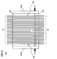
- FIG. 5 is a bottom view of the application unit 20 viewed from the direction of A in FIG.
- the coating unit 20 is provided with side wall members 24a, 24b for preventing the matrix resin 2 from leaking from both ends in the arrangement direction of the reinforcing fiber sheet 1a, and is surrounded by the wall members 21a, 21b and the side wall members 24a, 24b.
- An outlet 25 of the constricted portion 23 is formed in the closed space.
- the outlet 25 has a slit shape, and the sectional aspect ratio (Y / D in FIG. 3) may be set according to the shape of the reinforcing fiber sheet 1a to which the matrix resin 2 is to be applied.
- FIG. 6A is a cross-sectional view illustrating the structure inside the coating unit when the coating unit 20 is viewed from the direction B.
- the wall member 21b is omitted for easy viewing
- the reinforcing fiber sheet 1a depicts the reinforcing fibers 1 so as to be arranged with a gap therebetween. Arrangement without any gap is preferable from the viewpoint of the quality of the sheet prepreg and the mechanical properties of the FRP.
- FIG. 6 b shows the flow of the matrix resin 2 in the gap 26.
- a vortex flows in the matrix resin 2 in the direction of R. Since the vortex flow R becomes a flow (Ra) directed outward at the lower portion of the liquid pool 22, the reinforcing fiber sheet may be torn (breakage of the sheet-like fiber bundle occurs) or the spacing between the reinforcing fibers may be reduced. The reinforced fiber sheet prepreg may be spread, which may cause uneven arrangement of the reinforcing fibers.
- the reinforcing fiber sheet 1a is compressed in the width direction, and the end may be broken.
- Patent Literature 2 Japanese Patent No. 3252278
- the width of the gap 26 so as to suppress the generation of the vortex at the end.
- the width L of the liquid reservoir 22, that is, the interval L between the side plate members 24a and 24b may be configured to satisfy the following relationship with the width W of the reinforcing fiber sheet measured immediately below the narrowed portion 23. preferable. L ⁇ W + 10 (mm).
- the lower limit of L is not less than W-5 (mm) from the viewpoint of improving the uniformity of the dimension in the width direction of the prepreg 1b.
- the width regulation is performed at least at the lower part of the liquid reservoir 22 (the position G in FIG. 6A). Further, more preferably, when this width regulation is performed in the entire area of the liquid pool 22, the generation of the vortex flow R can be almost completely suppressed, and as a result, cracks and end breaks of the reinforcing fiber sheet can be almost completely prevented. Can be suppressed.
- the width regulation may be performed only on the liquid pool portion 22, but when the constriction portion 23 is similarly performed, the excess matrix resin 2 is applied to the side surface of the prepreg 1b. It is preferable from the viewpoint of suppressing this.
- the above-described coating step is basically the same as the first and second manufacturing methods. However, in the third manufacturing method, one or more bars are installed in the coating section. It is characterized by this that the impregnation proceeds. It is described in detail below.
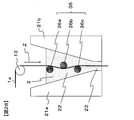
- the coating unit 20 by contacting the reinforcing fiber sheet 1a with a bar group 35 extending in the depth direction of the drawing inside the coating unit 20, air bubbles contained in the reinforcing fiber sheet 1a are squeezed out and discharged. Then, the matrix resin can be more efficiently impregnated inside the reinforcing fiber sheet 1a. Further, if necessary, the release sheet 3 can be applied to the prepreg 1c and wound up, as in the first and second manufacturing methods.
- the reinforcing fiber sheet 1a introduced into the liquid pool section 22 travels vertically downward Z while contacting the bars 35a, 35b, and 35c in this order inside the matrix resin 2.
- the reinforcing fiber sheet 1a is pressed against the bar, and the matrix resin 2 caught in the gap between the reinforcing fiber sheet 1a and the bar impregnates the inside of the reinforcing fiber sheet 1a and is contained inside the reinforcing fiber sheet 1a.
- the air bubbles are discharged to the outside of the reinforcing fiber sheet 1a from the surface opposite to the surface in contact with the bar so as to be squeezed out by the bar.
- the increased liquid pressure also has the effect of impregnating the inside of the reinforcing fiber sheet 1a with the matrix resin 2.
- This is based on the property (Darcy's law) that when a matrix material is impregnated into a porous body such as a reinforcing fiber bundle, the degree of impregnation increases with the pressure of the matrix resin. Even if the reinforcing fiber sheet 1a is insufficiently impregnated with the matrix resin 2 in the bar group 35, the matrix resin 2 is impregnated again in the lower part of the liquid reservoir 22, so that the prepreg 1b having a higher degree of impregnation is obtained. be able to. Also in this case, when the reinforcing fiber sheet 1a is run at a higher speed, the hydraulic pressure is further increased, so that the impregnation effect can be further enhanced.
- the reinforcing fiber sheet 1a is automatically centered at the center of the gap D by the increased liquid pressure, and the reinforcing fiber sheet 1a does not directly rub against the wall surface of the liquid reservoir 22 or the narrowed portion 23. It also has the effect of suppressing the generation of fluff. This is because when the reinforcing fiber sheet 1a approaches one of the gaps D due to disturbance or the like, the matrix resin 2 is pushed into the narrower gap on the approaching side and is compressed, so that the hydraulic pressure increases on the approaching side. Then, the reinforcing fiber sheet 1a is pushed back to the center of the gap D.
- the total amount of the matrix resin 2 applied to the reinforcing fiber sheet 1a can be controlled by the gap D of the narrowed portion 23.
- the wall members 21a and 21b may be installed so that the gap D is widened.
- the present invention is not limited to this. It is sufficient that the reinforcing fiber sheet 1a is substantially vertically downward as long as the reinforcing fiber sheet 1a can be stably and continuously driven. Further, when the reinforcing fiber sheet 1a is in contact with the bar group 35, the traveling direction of the reinforcing fiber sheet 1a changes, but the traveling direction of the reinforcing fiber sheet 1a is also substantially vertical as long as bubbles discharged from the reinforcing fiber sheet 1a do not accumulate around the bar group 35. It just needs to be downward.
- FIG. 7 shows an example in which the bar group 35 is composed of three bars 35a, 35b, and 35c in the application unit 40 in FIG. 7, but the present invention is not limited to this, and the number of bars may be one or more. Further, in the application section 40 of FIG. 7, all the bars are arranged so as to sink inside the matrix resin 2, but the present invention is not limited to this, and at least one or more bars are arranged so as to sink inside the matrix resin 2. It should just be. However, the greater the number of bars that come into contact with the reinforcing fiber sheet 1a inside the matrix resin 2, the higher the effect of the matrix resin impregnation becomes. Therefore, it is preferable to arrange a plurality of bars so as to sink inside the matrix resin 2. .
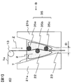
- FIG. 8 is a detailed cross-sectional view of the reinforcing fiber sheet 1a that contacts the bar 35 inside the matrix resin 2.
- FIG. The reinforcing fiber sheet 1a and the bar 35 are in contact at the holding angle ⁇ .
- the holding angle ⁇ is an angle formed by an arc connecting a point P1 at which the reinforcing fiber sheet 1a contacts the bar 35 and a point P2 at which the reinforcing fiber sheet 1a is separated from the bar 35 to a center point Pc of the bar 35.
- the possibility that the reinforcing fiber sheet 1a rubs against the bar 35 to generate fluff increases.
- the matrix resin 2 caught in the gap between the reinforcing fiber sheet 1a and the bar 35 is completely impregnated into the inside of the reinforcing fiber sheet 1a and depleted, the reinforcing fiber sheet 1a and the bar 35 directly rub against each other. The likelihood of occurrence increases rapidly.
- the holding angle ⁇ between the reinforcing fiber sheet 1a and the bar 35 is preferably set to 40 ° or less, and more preferably 20 ° or less.
- the holding angle ⁇ needs to be 10 ° or more.
- the cross-sectional shape of the bar 35 is circular, but the present invention is not limited to this, and the cross-sectional shape of the bar may be other than circular.
- a rectangular shape with rounded corners as shown in FIG. 9A or an elliptical shape as shown in FIG. 9B may be used.
- the surface that comes into contact with the reinforcing fiber sheet 1a has no sharp corners and has a smooth curve.
- the bar 35 does not need to be dense inside, and may be a hollow pipe, for example.
- the diameter (or representative length) of the cross section of the bar 35 is not particularly defined. However, as the diameter of the bar 35 increases, the length of contact between the reinforcing fiber sheet 1a and the bar 35 increases, and as described above, fluff may occur. It is preferable to reduce the diameter of the bar 35 to such an extent that the bar 35 is not deformed by the tension of the reinforcing fiber sheet 1a because the property is enhanced. Further, from the viewpoint of suppressing deformation of the bar 35, the material of the bar is preferably a highly rigid metal such as stainless steel.
- the surface of the bar 35 be finished smoothly. This is to make it difficult to generate fluff when the reinforcing fiber sheet 1a comes into contact with the bar 35.
- the matrix resin impregnation effect can be obtained by using a roll that rotates in the application section 40 as the bar 35.
- the matrix The bar 35 is preferably a non-rotating fixed member because a part of the reinforcing fiber sheet 1a may be wound around a roll due to the viscosity of the resin 2 and the reinforcing fiber sheet 1a may not be able to run.
- a guide roll (conveying roll) 13 is provided vertically above the application unit 40, and the reinforcing fiber sheet 1 a traveling in the horizontal direction is brought into contact with the guide roll 13 to move the traveling direction downward in the vertical direction. If the coating device 100 is guided after the change, the height of the coating device 100 in the vertical direction can be reduced, which is preferable from the viewpoint of reducing the construction cost of the building in which the coating device 100 is installed.
- the uppermost bar 35a of the bar group 35 is in contact with the reinforcing fiber sheet 1a on the surface opposite to the surface of the reinforcing fiber sheet 1a that is in contact with the guide roll 13. This is because the reinforcing fiber sheet 1a running on the guide roll 13 has a slight speed difference in the thickness direction due to the circumferential length difference, but the bar 35a has the reinforcing fiber sheet on the same side as the guide roll 13. This is because the above-mentioned speed difference further accumulates when contacting with 1a, and the reinforcing fiber sheet 1a becomes slack inside the application section 40.
- the width regulating mechanism 27a is provided between the side wall members 24a and 24b. 27b can be provided, and the width can be regulated by such a mechanism. This is preferable from the viewpoint that the width regulated by the width regulating mechanism can be freely changed, so that a matrix resin-impregnated reinforced fiber sheet having various widths can be manufactured by one application portion.
- the relationship between the width (W) of the matrix resin-impregnated reinforcing fiber sheet immediately below the constriction and the width (L2) regulated by the width regulating mechanism at the lower end of the width regulating mechanism is L2 ⁇ W + 10 (mm). Is more preferable, and L2 ⁇ W + 2 (mm) is more preferable. Further, the lower limit of L2 is adjusted to be not less than W-5 (mm), more preferably not less than W (mm), from the viewpoint of improving the uniformity of the dimension in the width direction of the matrix resin-impregnated reinforced fiber sheet prepreg 1b. Is preferred. There is no particular limitation on the shape and material of the width regulating mechanism, but a plate-shaped bush is simple and preferable.
- the width is smaller than the distance between the wall members 21a and 21b (see FIG. 10, which indicates the length in the vertical direction of the width regulating mechanism in the figure viewed from the Z direction). By having this, it is possible to prevent the matrix resin from flowing in the horizontal direction, which is preferable.
- the shape from the middle part to the lower part of the width regulating mechanism conforms to the internal shape of the application part, because the stagnation of the matrix resin in the liquid pool part can be suppressed and the deterioration of the matrix resin can be suppressed. In this sense, it is preferable that the width regulating mechanism is inserted up to the constriction 23.
- FIG. 10 shows an example of the plate-shaped bush 27 as the width regulating mechanism, but shows an example in which the lower part from the middle of the bush is inserted along the tapered shape of the liquid reservoir 22 to the constriction 23.
- FIG. 10 shows an example in which L2 is constant from the liquid level to the outlet, but the width regulated by the portion may be changed within a range that achieves the purpose of the width regulating mechanism.
- the width regulating mechanism can be fixed to the application section 20 by an arbitrary method. However, in the case of the plate-shaped bush 27, the plate-shaped bush 27 is deformed by high hydraulic pressure by fixing at a plurality of portions in the vertical direction. The fluctuation of the regulation width due to the above can be suppressed. For example, it is preferable to use a stay for the upper portion and to insert the lower portion into the application portion, since the width can be easily regulated by the width regulating mechanism.
- FIG. 11 is a detailed cross-sectional view when the application unit 40 in FIG. 7 is viewed from the direction B.
- the wall member 21b is omitted.
- Each of the bar groups 35 in FIG. 11 has a columnar shape having a uniform cross section.
- the matrix resin 2 caught in the gap between the reinforcing fiber sheet 1a and the bar 35 causes the reinforcing fiber sheet 1a. Not only impregnate the inside, but also flow from both ends of the reinforcing fiber sheet 1a in the direction of E in FIG.
- the fibers at both ends of the reinforcing fiber sheet 1a are also moved in the direction of E in FIG. If the reinforced fiber sheet 1a spreads, the width of the reinforcing fiber sheet 1a changes, or the density of the fibers at both ends of the reinforcing fiber sheet 1a decreases, so that the prepreg 1b of uniform quality cannot be obtained. Also, when a reinforced fiber fabric is used as the reinforced fiber sheet 1a, both ends of the reinforced fiber fabric may be pulled by the flow of the matrix resin 2, and the width may be changed. In the worst case, both ends of the reinforcing fiber sheet 1a may fall off from the bar group 35, making it impossible to run.
- UD base material unidirectional material in which the reinforcing fibers 1 are arranged in one direction
- FIG. 12 is a detailed cross-sectional view of the application section 41 of the embodiment different from FIG. 12, a bar group 36 having a width regulating member at both ends is provided instead of the bar group 35 having a uniform cross section.
- the width regulating member a disk-shaped member having a large diameter may be provided at both ends of each bar as shown in FIG.
- a plurality of bars may be formed by two parallel plates as shown in FIG. It may be sandwiched. Further, as shown in FIG. 15, the side plate member 24 of the liquid reservoir may be brought into contact with the bar group 36, and the side plate member 24 may be used as a width regulating member.
- the width regulating member shown in FIG. 13 it is preferable that the diameter d2 of the disc-shaped members at both ends of the bar satisfy the relationship of d2 ⁇ d1 + 1 (mm). This is to prevent the reinforcing fiber sheet 1a from falling off from both ends of the bar.
- the thickness W3 of the disk-shaped member may be large enough to prevent the disk-shaped member from being deformed by being pushed by the reinforcing fiber sheet 1a. Specifically, W3 is preferably set to 1 mm or more.
- the interval W2 inside the width regulating member of the bar group 36 is preferably equal to or less than the width W1 of the slit-shaped outlet. This is because if the interval W2 inside the width regulating member of the bar group 36 is wider than the width W1 of the slit-shaped outlet, the reinforcing fiber sheet 1a widened in the bar group 36 passes through the narrow slit-shaped outlet. This is because both ends of the reinforcing fiber sheet 1a may be rubbed at the slit-shaped outlet and fuzz may be generated.
- the interval W2 inside the width regulating member of the bar group 36 is too narrow with respect to the width W1 of the slit-shaped outlet, the narrow reinforcing fiber sheet 1a passing through the bar group 36 will suddenly become wider at the slit-shaped outlet. Is spread, and the arrangement of the fibers may be disturbed at both ends of the reinforcing fiber sheet 1a.
- the difference between the interval W2 inside the width regulating member of the bar group 36 and the width W1 of the slit-shaped outlet exceeds 10 mm, the arrangement of the fibers may be disturbed at both ends of the reinforcing fiber sheet 1a.
- the liquid pressure is increased in the running direction of the reinforcing fiber sheet by continuously decreasing the cross-sectional area in the running direction of the reinforcing fiber sheet in the liquid reservoir 22. It is important to note that the continuous decrease in the cross-sectional area in the running direction of the reinforcing fiber sheet is not particularly limited as long as the hydraulic pressure can be continuously increased in the running direction.
- the liquid reservoir may have a curved shape such as a tapered shape (linear shape) or a trumpet shape.
- cross-sectional area decreasing portion may be continuous over the entire length of the liquid pool portion, or may include a portion where the cross-sectional area does not decrease or a portion which expands conversely as long as the object and effects of the present invention can be obtained. You may go out. These will be described in detail below with reference to FIGS. 16 to 19.
- FIG. 16 is a detailed cross-sectional view of the application section 20b of another embodiment different from FIG. It is the same as the coating unit 20 of FIG. 4 except that the shapes of the wall members 21c and 21d forming the liquid pool 22 are different.
- the liquid reservoir 22 may be divided into a region 22a in which the cross-sectional area continuously decreases in the vertical direction Z downward and a region 22b in which the cross-sectional area does not decrease.
- the vertical height H at which the cross-sectional area is continuously reduced is preferably 10 mm or more.
- the vertical height H at which the more preferable cross-sectional area is continuously reduced is 50 mm or more.
- the distance by which the matrix resin 2 entrained by the reinforcing fiber sheet 1a is compressed in the region 22a where the cross-sectional area of the liquid reservoir 22 is continuously reduced is secured, and the liquid generated in the lower portion of the liquid reservoir 22 is secured.
- the pressure can be increased sufficiently. As a result, it is possible to prevent the fluff from clogging the constricted portion 23 due to the liquid pressure, and to obtain the effect that the matrix resin 2 impregnates the reinforcing fiber sheet 1a with the liquid pressure.
- the opening angle ⁇ of the taper is smaller. More specifically, it is preferable to form an acute angle (90 ° or less). Thereby, the compression effect of the matrix resin 2 can be enhanced in the region 22a (tapered portion) where the cross-sectional area of the liquid reservoir 22 is continuously reduced, and a high liquid pressure can be easily obtained.
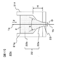
- FIG. 17 is a detailed cross-sectional view of the application unit 20c according to another embodiment different from FIG.
- the configuration is the same as the application unit 20b in FIG. 16 except that the wall members 21e and 21f forming the liquid reservoir 22 have a two-step tapered shape.
- the region 22a where the cross-sectional area of the liquid reservoir 22 is continuously reduced may be configured by a multi-stage taper portion of two or more stages. At this time, it is preferable to make the opening angle ⁇ of the tapered portion closest to the constricted portion 23 an acute angle from the viewpoint of enhancing the compression effect. Also in this case, it is preferable that the height H of the region 22a where the cross-sectional area of the liquid reservoir 22 is continuously reduced is 10 mm or more.
- the vertical height H at which the more preferable cross-sectional area is continuously reduced is 50 mm or more.
- the area 22 a where the cross-sectional area of the liquid reservoir 22 is continuously reduced is formed as a multi-stage tapered portion, so that the volume of the matrix resin 2 that can be stored in the liquid reservoir 22 is maintained while the constriction portion 23 is maintained. Can be further reduced. As a result, the liquid pressure generated in the lower portion of the liquid reservoir 22 is further increased, and the effect of removing fluff and the effect of impregnating the matrix resin 2 can be further enhanced.
- FIG. 18 is a detailed cross-sectional view of the application section 20d of another embodiment different from FIG.
- the configuration is the same as the application unit 20b in FIG. 16 except that the shape of the wall members 21g and 21h constituting the liquid reservoir 22 is stepped.
- the effect of increasing the hydraulic pressure which is the object of the present invention, can be obtained.
- the volume can be increased. As a result, even when the matrix resin 2 cannot be continuously supplied to the application section 20d, the matrix resin 2 can be continuously applied to the reinforcing fiber sheet 1a for a long time, and the productivity of the reinforcing fiber sheet prepreg 1b is further improved. .
- FIG. 19 is a detailed cross-sectional view of the application unit 20e of another embodiment different from FIG. It is the same as the application section 20b in FIG. 16 except that the shape of the wall members 21i and 21j constituting the liquid pool section 22 is a trumpet shape (curved shape).
- the region 22a where the cross-sectional area of the liquid reservoir 22 is continuously reduced is tapered (linear), but is not limited to this.
- a trumpet shape (curved shape) as shown in FIG. May be.
- the reinforcing fiber sheet 1a is caught by the step, and there is a concern that fluff is generated at this part.
- the region where the cross-sectional area of the liquid reservoir 22 is continuously reduced is a trumpet-like shape, the opening of the virtual tangent line at the lowermost part of the region 22a where the cross-sectional area of the liquid reservoir 22 is continuously reduced. It is preferable that the angle ⁇ be an acute angle.
- the cross-sectional area of the liquid reservoir does not necessarily have to be smoothly reduced unless the object of the present invention is impaired.
- FIG. 20 is a detailed cross-sectional view of the application unit 30 according to another embodiment different from the present invention.
- the liquid reservoir 32 in FIG. 20 does not include a region in which the cross-sectional area continuously decreases in the vertical direction Z, and the cross-sectional area is discontinuous and sharp at the boundary 33 with the constriction 23. It is a structure which reduces to. For this reason, the reinforcing fiber sheet 1a tends to be clogged at the narrowed portion.
- a traveling mechanism for transporting the reinforcing fiber sheet or the prepreg of the present invention As a traveling mechanism for transporting the reinforcing fiber sheet or the prepreg of the present invention, a known roller or the like can be suitably used. In the present invention, since the reinforcing fiber sheet is conveyed vertically downward, it is preferable to arrange rollers vertically above and below the application section.
- the running path of the reinforcing fiber sheet is as straight as possible in order to suppress the arrangement disorder and the fluffing of the reinforcing fiber.
- the sheet-like integrated material which is a laminate of the prepreg and the release sheet
- wrinkles may occur due to a difference in circumference between the inner layer and the outer layer.
- the path is as straight as possible. From this viewpoint, it is preferable to use a nip roll in the traveling path of the sheet-like integrated object.
- Whether the S-shaped roll or the nip roll is used can be appropriately selected according to the manufacturing conditions and the characteristics of the product.
- impregnation proceeds in the application section, and thereafter, additional impregnation can be performed to further advance the impregnation.
- the temperature of the matrix resin-impregnated reinforcing fiber sheet 1b immediately below the application section 20 is higher than room temperature. Therefore, if additional impregnation is performed immediately after leaving the application section, a heating device such as a hot plate for reheating the matrix resin-impregnated reinforced fiber sheet 1b without being cooled to room temperature can be omitted or simplified. .
- the prepreg 1c adjusted to a desired degree of impregnation can be obtained by providing the additional impregnating device 19 immediately below the application section and performing additional impregnation. For this reason, the distance N from the application section outlet to the additional impregnation start point is within 1 m. N is preferably 0.5 m or less.
- a non-contact heating device is disposed as a re-impregnation device, and re-impregnation by non-contact heating can be performed.
- the viscosity of the matrix resin contained in the matrix resin-impregnated reinforced fiber sheet 1b is increased by increasing the temperature, whereby the impregnation can be advanced by capillary action.
- P2 surface temperature of the matrix resin-impregnated reinforced fiber sheet at the end of heating
- M ° C.
- ⁇ P2 (° C.) is preferably M + 30 (° C.) or more, because impregnation is more likely to proceed.
- the distance from the application section outlet to the additional impregnation start point is a distance N2 from the application section exit to the heating start point by the non-contact heating device (see FIG. 26).
- a non-contact heating means infrared rays, far infrared rays, laser, heat medium (for example, steam or the like) can be used, but infrared rays are the most simple and preferable.
- the heating distance is not particularly limited as long as the temperature can be raised to the desired temperature up to the matrix resin-impregnated reinforced fiber sheet, but is preferably 1 m or less from the viewpoint of simplifying the apparatus.
- the heating distance is preferably 0.5 m or less.
- the pressing of the matrix resin-impregnated reinforced fiber sheet is not performed by using the non-contact heating device, the reinforced fiber layer may be disturbed by the surface tension of the matrix resin. For this reason, after performing additional impregnation by non-contact heating, it is also preferable to adjust the shape of the prepreg and the shape and arrangement of the reinforcing fiber layer by applying pressure.
- the pressing means a nip roll, an S-shaped roll, or the like is used. Can be.
- an apparatus provided with a pressurizing means can be used as the additional impregnation device.
- the distance N from the outlet of the application section to the pressure start point of the additional impregnation is 1 m or less, and the surface temperature P (° C.) of the matrix resin-impregnated reinforced fiber sheet before the additional impregnation is equal to the internal temperature of the application section.
- the temperature M (° C.) of the matrix resin stored inside the coating section 20 can be measured with a thermocouple.
- the surface temperature P (° C.) of the matrix resin-impregnated reinforced fiber sheet before additional impregnation can be measured with a radiation thermometer. Although the emissivity differs depending on the measurement object, the emissivity is assumed to be uniformly measured at 0.95.
- the measurement position of the surface temperature P (° C.) of the matrix resin-impregnated reinforcing fiber sheet 1 b is measured at a distance of 10 cm from the application start point of the additional impregnation to the application section 20.
- the matrix resin-impregnated reinforced fiber sheet 1b is located as close to the pressure start point as possible.
- the surface temperature P (° C.) is measured. Note that the measurement point is at the center in the width direction of the matrix resin-impregnated reinforced fiber sheet 1b.
- the measurement can be performed using an infrared radiation thermometer AD-5611A (manufactured by A & D Corporation, emissivity 0.95 fixed).
- the additional impregnation of the matrix resin-impregnated reinforced fiber sheet 1b immediately below the application section 20 is referred to as additional impregnation or additional impregnation in order to distinguish the impregnation at the application section.
- the obtained sheet is called prepreg 1c.
- the release sheet 3 by providing the release sheet 3, it is possible to prevent the matrix resin impregnated with the matrix resin of the roll or the device that comes into contact with the matrix resin-impregnated reinforcing fiber sheet 1b or the prepreg 1c during the manufacturing process. Since the running properties of the matrix resin-impregnated reinforced fiber sheet 1b and the prepreg 1c are improved, the release sheet 3 can be provided before the matrix resin-impregnated reinforced fiber sheet 1b is additionally impregnated.
- the release sheet 3 applied in the present invention is applied to the reinforcing fiber sheet 1a by heating the matrix resin 2 to a temperature higher than room temperature, before applying the release sheet 3 to the matrix resin-impregnated reinforcing fiber sheet 1b.
- the release sheet may be heated. Heating before applying the release sheet 3 is preferable because the surface temperature of the matrix resin-impregnated reinforced fiber sheet 1b with which it comes into contact can be significantly reduced and the impregnation degree can be suppressed.
- the heating device in the additional impregnation device can be omitted or simplified.
- the surface temperature T (° C.) of the release sheet before applying to the matrix resin-impregnated reinforced fiber sheet is too low than the surface temperature K (° C.) of the matrix resin-impregnated reinforced fiber sheet 1b before applying the release sheet, If the surface temperature T (° C.) of the release sheet before coming into contact with the matrix resin-impregnated reinforced fiber sheet is too high, the matrix resin-impregnated reinforced fiber sheet 1b will be removed from the matrix resin-impregnated reinforced fiber sheet 1b during additional impregnation. It protrudes and it becomes difficult to continue additional impregnation.
- the heating device for heating the release sheet 3 is not particularly limited, and various heating means such as air heating, infrared heating, far infrared heating, laser heating, contact heating, and heating medium heating (such as steam) can be used. Can be used.
- the surface temperature K (° C.) of the matrix resin-impregnated reinforced fiber sheet can be measured with a radiation thermometer. Although the emissivity differs depending on the measurement object, the emissivity is assumed to be uniformly measured at 0.95. As an example, the measurement can be performed using an infrared radiation thermometer AD-5611A (manufactured by A & D Corporation, emissivity 0.95 fixed).
- the surface temperature P (° C.) of the matrix resin-impregnated reinforced fiber sheet 1b before the additional impregnation cannot be directly measured when the release sheet 3 is provided, the surface temperature of the applied release sheet is measured and P ( ° C).
- the measurement position of P is measured at a distance of 10 cm from the starting point of the additional impregnation to the application section 20 side from the starting point.
- the measurement position of the surface temperature T (° C.) of the release sheet 3 is measured from a place where the release sheet 3 and the matrix resin-impregnated reinforced fiber sheet 1b are in contact with each other, at a distance of 10 cm to the release sheet supply device 18 side. I do. Note that the measurement point is the center of the release sheet 3 in the width direction.
- the measurement position of the surface temperature K (° C.) of the matrix resin-impregnated reinforced fiber sheet 1 b before applying the release sheet is measured at a position 10 cm away from the application section 20 starting from a place in contact with the release sheet 3. .
- the measurement is made at a place as close as possible to the place where the matrix resin-impregnated sheet and the release sheet come into contact. Note that the measurement point is at the center in the width direction of the matrix resin-impregnated reinforced fiber sheet 1b.
- the surface temperature P2 (° C.) of the matrix resin-impregnated reinforced fiber sheet at the thermal end point in the first production method can also be measured with a radiation thermometer.
- the measurement position is to measure the surface temperature of the prepreg 10 cm downstream from the non-contact heating device.
- the pressurizing method of the additional impregnation device 19 is not particularly limited.
- Preferable examples include a nip roll system that can reduce the roll diameter, set pressure, and contact length between the prepreg and the roll and can reduce the size of the device, and an S-shaped roll system that can obtain a take-up capability as well as impregnation by taking a large pressurized area.
- the pressing method is a nip roll
- the impregnation load obtained by dividing the force applied to the nip roll by the prepreg width is preferably 0.1 N / mm to 40 N / mm or less.
- the impregnation degree is too low, the impregnation degree is too low, and if it is too high, the matrix resin may protrude in the width direction, or the width of the prepreg may be excessively widened, so that a prepreg having a targeted basis weight may not be obtained.
- the roll When the matrix resin 2 is heated to a temperature higher than room temperature and applied to the reinforcing fiber sheet 1a, and a roll is used for pressurization during additional impregnation, the roll preferably has a heating mechanism. Thereby, a decrease in the surface temperature of the matrix resin-impregnated reinforced fiber sheet 1b can be suppressed, and high impregnation properties can be obtained.
- the additional impregnation device may have a heating device before pressurization. By heating the matrix resin-impregnated reinforced fiber sheet 1b before pressurization, the temperature of the matrix resin is increased, the viscosity of the matrix resin in the matrix resin-impregnated reinforced fiber sheet 1b is reduced, and high impregnation properties are obtained.
- the viscosity of the matrix resin in the matrix resin-impregnated reinforced fiber sheet 1b before the additional impregnation and pressurization may be low. Therefore, the viscosity of the matrix resin in the matrix resin-impregnated reinforced fiber sheet 1b before pressing is preferably 80 Pa ⁇ s or less when measured at a strain rate of 3.14 s ⁇ 1 . Since it is difficult to directly measure the viscosity of the matrix resin in the matrix resin-impregnated reinforced fiber sheet 1b before pressurization, the matrix resin-impregnated reinforced fiber sheet surface temperature P (° C.) before the additional impregnation described above is entered. , The matrix resin viscosity measured at a strain rate of 3.14 -1 is preferably 80 Pa ⁇ s or less.
- the additional impregnating device the following exemplified devices can be appropriately selected.
- a laminate of a sheet-like carbon fiber bundle and a resin is preheated by a hot plate to sufficiently soften the resin on the sheet-like carbon fiber bundle.
- the impregnation can also be advanced by using a device that presses with a heated nip roll.
- the temperature of the hot plate for preheating, the surface temperature of the nip roll, the linear pressure of the nip roll, and the diameter and number of the nip rolls can be appropriately selected so as to obtain a desired impregnation degree.
- FIG. 1 shows an example in which the prepreg sheet runs in an S-shape, but if impregnation is possible, the contact length between the sheet and the roll, such as a U-shape, V-shape or ⁇ -shape, is described. May be adjusted.
- the impregnation pressure is increased to increase the degree of impregnation, it is also possible to add an opposing contact roll. Further, as shown in FIG.
- the state of the impregnation of the matrix resin can be checked by checking the inside by tearing the collected prepreg and visually examining the inside, and more quantitatively evaluated by, for example, a peeling method. It is possible to The impregnation rate of the matrix resin by the peeling method can be measured as follows. That is, the collected prepreg is sandwiched between adhesive tapes, and the prepreg is peeled off to separate the reinforcing fibers to which the matrix resin has adhered from the reinforcing fibers to which the matrix resin has not adhered.
- the ratio of the mass of the reinforcing fibers to which the matrix resin has adhered to the mass of the entire reinforcing fiber sheet put in can be taken as the impregnation rate of the matrix resin by the peeling method.
- the impregnation degree by the peeling method is 80% or more, it is preferable from the viewpoint of handling of the prepreg.
- a high tension take-up device for drawing out the prepreg from the application section downstream of the application section. This is because high frictional force and shear stress are generated between the reinforcing fiber sheet and the matrix resin in the application section, and it is preferable to generate a high take-up tension downstream of the process in order to overcome the drawback and draw out the prepreg. It is.
- a nip roll or an S-shaped roll can be used, but by increasing the frictional force between the roll and the prepreg, slip can be prevented and stable running can be achieved. .
- the S-shaped roll is preferable because the frictional force can be easily controlled by the roll diameter and the contact length.
- a release sheet feeding device or a winder can be used as appropriate, and as such a device, a known device can be used. It is preferable to provide a mechanism capable of feeding back the winding tension or feeding back the winding speed from the viewpoint of stable running of the sheet.
- the prepreg which is a kind of the precursor of FRP, is one form of the reinforcing fiber sheet obtained in the present invention
- the case where the present invention is applied to the FRP application will be described below by referring to the reinforcing fiber sheet as a prepreg.
- the width of the prepreg is not particularly limited, and may be a wide width of about several tens cm to 2 m, or a tape having a width of several mm to several tens mm.
- the width can be selected according to the application.
- devices called ATL (Automated Tape Laying) and AFP (Automated Fiber Placement) for automatically laminating narrow prepregs and prepreg tapes have been widely used. Therefore, it is also preferable that the width is adjusted to this.
- ATL often uses narrow prepregs having a width of about 7.5 cm, about 15 cm, or about 30 cm.
- AFP often uses prepreg tapes having a width of about 3 mm to about 25 mm.
- the width of the coating portion used in the present invention can be adjusted so as to have a desired width from the beginning. For example, when manufacturing a narrow prepreg having a width of 30 cm for ATL, the width of the application section outlet may be adjusted accordingly. In addition, in order to manufacture this efficiently, it is preferable to manufacture the product with a product width of 30 cm. When a plurality of such manufacturing devices are arranged in parallel, the same traveling device / transport device, various rolls, and a winder are used. The prepreg of the line can be manufactured.
- a reinforcing fiber sheet in the form of a tape-shaped reinforcing fiber bundle having a length of about 1 to 3 threads is formed and passed through a coating section whose width has been adjusted so as to obtain a desired tape width. You can also get it.
- the accuracy of the tape width is often required from the viewpoint of controlling the lateral overlap between the tapes. For this reason, it is preferable to more strictly control the outlet width of the application section.
- the above L, L2, and W satisfy the relationship of L ⁇ W + 1 mm and / or L2 ⁇ W + 1 mm. .
- the method of slitting the prepreg is not particularly limited, and a known slit device can be used. After winding the prepreg once, it may be installed in the slit device again to perform slitting, or for efficiency, a slitting step may be arranged continuously from the prepreg producing step without winding the prepreg once. Also, in the slitting step, a wide prepreg of 1 m or more may be directly slit to a desired width, or once cut and divided into narrow prepregs of about 30 cm, and then slit again to a desired width. good.
- a release sheet may be supplied independently, or one wide release sheet may be supplied.
- a plurality of prepregs may be stacked.
- the end in the width direction of the prepreg thus obtained can be cut off and supplied to an ATL or AFP device.
- the matrix resin component resin in the case of CFRP
- adhering to the slit cutter blade can be reduced, and the cleaning cycle of the slit cutter blade is extended. There is also an advantage that you can do it.
- the matrix resin is stored in the coating section, but it is preferable to appropriately supply the matrix resin because the coating proceeds.
- the mechanism for supplying the matrix resin to the application section is not particularly limited, and a known device can be used. It is preferable that the matrix resin be continuously supplied to the application section because the running of the reinforcing fiber sheet can be stabilized without disturbing the liquid level above the application section.
- the self-weight can be supplied as a driving force from a tank storing the matrix resin, or can be supplied continuously using a pump or the like.
- a pump, a gear pump, a tube pump, a pressure pump, or the like can be used as appropriate according to the properties of the matrix resin.
- the matrix resin When the matrix resin is solid at room temperature, it is preferable to provide a melter above the reservoir. Further, a continuous extruder or the like can be used. Further, it is preferable to provide a mechanism capable of continuously supplying the matrix resin in accordance with the applied amount so that the liquid level above the application portion of the matrix resin is as constant as possible. For this purpose, for example, a mechanism that monitors the liquid level, the weight of the application section, and the like and feeds it back to the supply device is conceivable.
- the online monitoring method is not particularly limited, and a known method can be used.
- a device for measuring the thickness for example, a beta-ray meter or the like can be used.
- the application amount monitored online is immediately fed back to the application unit, and can be used for adjusting the temperature of the application unit and the gap D (see FIG. 2) of the constricted portion 23.
- Application amount monitoring can of course be used as defect monitoring.
- As the thickness measurement position for example, in FIG.
- the thickness of the reinforcing fiber sheet 416 can be measured near the direction change roll 419, and the thickness of the prepreg can be measured near the high tension take-up device 444. It is also preferable to perform online defect monitoring using infrared rays, near infrared rays, a camera (image analysis), or the like.
- the prepreg manufacturing apparatus of the present invention includes a traveling mechanism for running the reinforcing fiber sheet substantially vertically downward, an application mechanism for applying a matrix resin to the reinforcing fiber sheet to obtain a matrix resin-impregnated reinforced fiber sheet, and a matrix resin impregnation.
- a re-impregnation mechanism that presses the reinforcing fiber sheet at least, and a release sheet supply that supplies a release sheet to apply a release sheet to at least one surface of the matrix resin-impregnated sheet before performing additional re-impregnation on the matrix resin-impregnated sheet
- a prepreg manufacturing apparatus having a mechanism and a heating mechanism for heating a release sheet, wherein the coating mechanism is capable of storing a coating liquid therein, and further includes a liquid reservoir and a constricted part that are communicated with each other.
- the liquid reservoir has a portion whose cross-sectional area continuously decreases along the running direction of the sheet-like reinforcing fiber bundle,
- the constricted portion has a slit-shaped cross-section, and has a cross-sectional area smaller than the upper surface of the liquid reservoir, and the additional impregnation mechanism is arranged such that the pressure start point of the additional impregnation is within 1 m from the application mechanism,
- This is a prepreg manufacturing apparatus having a release sheet heating mechanism between a release sheet supply mechanism and an impregnation mechanism.
- FIG. 21 is a schematic view showing an example of a manufacturing process / apparatus of the first manufacturing method of the present invention.
- the plurality of reinforcing fiber bobbins 412 are hung on creels 411. Then, the reinforcing fiber bundle 414 can be pulled out with a constant tension by the brake mechanism provided to the creel.
- the plurality of pulled out reinforcing fiber bundles 414 are orderly arranged by the reinforcing fiber arrangement device 415, and the reinforcing fiber sheet 416 is formed.
- FIG. 21 only three yarns are drawn on the reinforcing fiber bundle, but in practice, it can be one yarn to several hundred yarns, and can be adjusted to have a desired prepreg width and fiber weight. is there.
- the sheet is conveyed via a widening device 417 and a smoothing device 418, and a direction change roll 419.
- the reinforcing fiber sheet 416 is linearly conveyed between the reinforcing fiber arrangement device 415 and the direction change roll 419 between the devices.
- the widening device 417 and the smoothing device 418 can be appropriately skipped or the devices can be omitted depending on the purpose.
- the arrangement order of the reinforcing fiber arrangement device 415, the widening device 417, and the smoothing device 418 can be appropriately changed according to the purpose.
- the reinforcing fiber sheet 416 travels vertically downward from the direction changing roll 419, passes through the reinforcing fiber preheating device 420, and the application section 430, and the matrix resin impregnated reinforcing fiber sheet 421 is obtained. Then, the trix resin-impregnated reinforced fiber sheet 421 is passed through a non-contact heating device 423 installed at a distance N immediately below the application section 430 to advance impregnation. Further, a release sheet is provided on the direction change roll 445, and the sheet-like integrated body is cooled by the cooling device 461, is taken up by the take-up device 462, peels off the upper release sheet 446, and is then taken up by the winder 464.
- FIG. 22 is a schematic view showing an example of a manufacturing process / apparatus of the second manufacturing method of the present invention.
- the plurality of reinforcing fiber bobbins 412 are hung on a creel 411, and are pulled out upward through a direction changing guide 413. At this time, the reinforcing fiber bundle 414 can be pulled out with a constant tension by the brake mechanism provided to the creel.
- the plurality of pulled out reinforcing fiber bundles 414 are orderly arranged by the reinforcing fiber arrangement device 415, and the reinforcing fiber sheet 416 is formed.
- the sheet is conveyed vertically downward through a widening device 417, a smoothing device 418, and a direction change roll 419.
- the reinforcing fiber sheet 416 is linearly conveyed between the reinforcing fiber arrangement device 415 and the direction change roll 419 between the devices.
- the widening device 417 and the smoothing device 418 can be appropriately skipped or the devices can be omitted depending on the purpose.
- the arrangement order of the reinforcing fiber arrangement device 415, the widening device 417, and the smoothing device 418 can be appropriately changed according to the purpose.
- the reinforcing fiber sheet 416 travels vertically downward from the direction changing roll 419, passes through the reinforcing fiber preheating device 420, and the application section 430, and the matrix resin impregnated reinforcing fiber sheet 421 is obtained.
- the coated matrix resin-impregnated reinforced fiber sheet 421 is unwound from the release sheet supply device 442, the release sheet 446 is applied to both sides, and reaches the high tension take-up device 444 via the additional impregnation device 440.
- the release sheet 446 is provided from both sides, but may not be provided, or may be provided on only one side.
- the release sheet 446 may be heated by the release sheet heating device 422.
- the application section 430 can adopt any application section shape as long as the object of the present invention is achieved. For example, there are shapes as shown in FIG. 4, and FIGS. Further, a bush 27 can be provided as shown in FIG. Further, as shown in FIG. 7, a bar can be provided in the application section.
- the additional impregnating device can employ any device configuration as long as the object of the present invention is achieved.
- an additional impregnation device including a heating nip roll 452 is illustrated as the additional impregnation device 440.
- the prepreg / release sheet (sheet-like integrated material) 472 having a high degree of impregnation can be obtained by passing through the additional impregnation device.
- the heating nip roll 452 is drawn as an example of the pressing method, but a small heating S-shaped roll may be used depending on the purpose.
- the sheet-like integrated body is cooled by the cooling device 461, is taken by the take-up device 462, peels off the upper release sheet 446, and is wound up by the winder 464 to be a prepreg / release sheet to be a product.
- a sheet-like integrated body 472 can be obtained.
- the drawing of the matrix resin supply device and the online monitoring device is omitted.
- FIG. 23 is a schematic view of another example of a prepreg manufacturing process / apparatus using the second manufacturing method.
- the reinforcing fiber bundle 414 is pulled out from the creel 411, the reinforcing fiber sheet 416 is formed as it is by the reinforcing fiber arranging device 415, and then is linearly conveyed to the widening device 417 and the smoothing device 418. 23 in that the sheet 416 is guided upward.
- FIG. 24 is a schematic view of another example of a prepreg manufacturing process / apparatus using the present invention.
- a creel 411 is installed on the floor, and the traveling path of the reinforcing fiber sheet 416 is further linearized.
- FIG. 25 is a schematic view of another example of a prepreg manufacturing process / apparatus using the present invention.
- an example is shown in which the heated S-shaped roll 455 is also used as a high tension take-up device.
- the entire prepreg manufacturing apparatus can be made very compact.
- the arrangement of the contact rolls 456 is illustrated to increase the degree of impregnation, the arrangement is not necessary.
- first, second, and third manufacturing methods of the present invention can be used in an appropriate combination.
- Examples 1 to 3 correspond to the first manufacturing method
- Examples 4 to 5 correspond to the second manufacturing method
- Examples 6 to 15 correspond to the third manufacturing method.
- Prepreg manufacturing equipment As the prepreg manufacturing apparatus, an apparatus having a configuration shown in FIG. 26 for the first manufacturing method, an apparatus shown in FIG. 22 for the second manufacturing method, and an apparatus shown in FIG. Note that a widening device, a smoothing device, and a cooling device were not used.
- a coating section of a coating section 20c type shown in FIG. 17 is used as the coating section, and the coating section is made of stainless steel.
- a ribbon heater was wound around the outer periphery, and the temperature and viscosity of the matrix resin could be adjusted while measuring the temperature with a thermocouple.
- the running direction of the reinforcing fiber sheet in the liquid reservoir is vertically downward, and the liquid reservoir has a two-stage tapered shape.
- the first-stage taper has an opening angle of 17 ° and a taper height (ie, H) of 100 mm.
- the opening angle of the second-stage taper was 7 °.
- a plate-shaped bush 27 adapted to the inner shape of the application portion as shown in FIG. 10 was provided, L2 was set to 20 mm, and the gap D of the constricted portion was set to 0.2 mm.
- the outside of the stenosis portion was closed off from the bush so that the matrix resin did not leak from the stenosis portion exit.
- the liquid reservoir 22 is a tapered flow path whose cross-sectional area continuously decreases.
- the height H of the liquid reservoir 22 is 100 mm
- the opening angle ⁇ of the tapered portion is 30 °
- the gap D of the constricted portion 23 is 0. 0.2 mm (slit shape, aspect ratio 100).
- Stainless steel blocks were used for the wall members 21a and 21b forming the liquid reservoir 22 and the constricted portion 23.
- a stainless steel plate was used for the side plate member 24.
- a ribbon heater was wound around the wall member 21 and the side plate member 24, and the temperature of the epoxy resin as the matrix resin was adjusted to 90 ° C. while measuring the temperature with a thermocouple.
- Release paper having a width of 100 mm was used as the release sheet.
- the release sheet heating device was used in Example 5 and Comparative Example 5.
- a heat gun was used as a heating device for the release sheet. The heat gun was placed at a position 30 cm from the place where the matrix resin-impregnated reinforcing fiber sheet and the release sheet were in contact with the release sheet supply device side to heat the release sheet. The distance at which the heat gun is applied to the release sheet is adjusted, and the temperature at the center of the release sheet in the width direction is 90 ° C. at a position 10 cm away from the place where the matrix resin impregnated reinforced fiber sheet and the release sheet come into contact with each other. It was made to become. The location of the release sheet in contact with the matrix resin-impregnated reinforced fiber sheet was 30 cm from the outlet of the application section on the side of the high tension take-up device.
- ⁇ Addition impregnation device> In the first manufacturing method, a non-contact heating device using an infrared heater was used. The length of the heating section was 0.5 m.
- the nip roll near the coating unit side is installed so that the distance N from the coating unit outlet to the pressure start point of the additional impregnating device is 0.5 m, and the nip roll near the high tension take-up device side is near the coating unit side.
- the nip roll was set so that the distance between the nip roll and the pressure start point was 100 mm.
- the diameter of the nip roll was 50 mm.
- the nip force of the nip roll during pressurization was 400 N.
- Matrix resin A thermosetting epoxy resin composition
- It is a mixture of an epoxy resin (a mixture of an aromatic amine type epoxy resin and a bisphenol type epoxy resin), a curing agent (diaminodiphenyl sulfone), and a polyether sulfone.
- the viscosity of this thermosetting epoxy resin 1 was measured using ARES-G2 manufactured by TA Instruments at a measurement frequency of 0.5 Hz and a heating rate of 1.5 ° C./min.
- 80 ° C. 80 Pa ⁇ s at 70 ° C., 51 Pa ⁇ s at 75 ° C., and 15 Pa ⁇ s at 90 ° C.
- the degree of impregnation was 90% or more of Excellent, 70% or more and less than 90% Good, and less than 70% Bad.
- the temperature at the center of the matrix resin-impregnated reinforced fiber sheet was measured 10 cm downstream of the non-contact heating device.
- the surface temperature P (° C.) of the matrix resin-impregnated reinforced fiber sheet before the additional impregnation in Example 4 and Comparative Example 6 of the second production method is a distance of 10 cm from the starting point of pressing the nip roll near the application section to the application section.
- the surface temperature at the center in the width direction at the location was measured.
- the surface temperature P (° C.) of the matrix resin-impregnated reinforced fiber sheet before the additional impregnation in Example 5, Comparative Example 2, and Comparative Example 5 is a pressure starting point of the nip roll near the application section side because the release sheet is provided.
- the surface temperature of the release sheet at the center in the width direction at a distance of 10 cm to the application portion side was measured as P. Furthermore, the surface temperature T (° C.) of the release sheet before contacting the matrix resin-impregnated reinforced fiber sheet of Example 5, Comparative Example 4, or Comparative Example 5 using the release sheet is determined by the release sheet and the matrix resin-impregnated reinforced fiber. The surface temperature at the central portion in the width direction at a point at a distance of 10 cm from the place where the sheet was in contact with the release sheet feeding device side was measured.
- the surface temperature K (° C.) of the matrix resin-impregnated reinforced fiber sheet before applying the release sheet is determined at the center in the width direction at a distance of 10 cm from the place where the release sheet and the matrix resin-impregnated sheet come in contact with the application section side. The surface temperature was measured.
- the running speed of the reinforcing fiber sheet and the prepreg was 10 m / min.
- the impregnation degree of the obtained prepreg was evaluated, it was Good at 92%.
- the cross section of the composite after lamination and curing was observed, no disturbance of the carbon fiber layer was observed, and the prepreg quality was good.
- Comparative Example 3 An experiment was conducted in the same manner as in Comparative Example 2 except that the distance N2 from the outlet of the coating section to the non-contact heating device was 1.3 m, and the running speed of the prepreg was 0.5 m / min. Although it was possible to raise the temperature to 90 ° C., when the composite cross section after lamination and curing was observed, the carbon fiber layer was disturbed, and the prepreg quality was poor.
- Example 4 A reinforcing fiber is drawn out from a reinforcing fiber bobbin hung on a creel, three reinforcing fiber yarns are arranged in a width direction by a reinforcing fiber arrangement device, a reinforcing fiber sheet is formed, and a matrix resin A heated to 90 ° C. was led to a coating section for storing, and the matrix resin A was coated. Thereafter, the matrix resin-impregnated reinforced fiber sheet was pulled out from the application section, installed so that the distance N from the application section exit to the pressure start point of the additional impregnation device was 0.5 m, and two heating nip rolls set at 100 ° C.
- a prepreg was obtained by passing a matrix resin-impregnated reinforced fiber sheet through an additional impregnation device, and was wound up with a winder.
- the running speed of the reinforcing fiber sheet and the prepreg was set to 20 m / min.
- the degree of impregnation of the obtained prepreg was evaluated, it was good at 80% or more.
- the surface temperature P of the matrix resin-impregnated reinforced fiber sheet before entering the additional impregnation device was 70 ° C.
- Example 5 The release paper was peeled off using a release sheet (upper) winding device 463 in the same manner as in Example 4 except that a release sheet heated to a surface temperature of 90 ° C. was provided before entering the additional impregnation device. A sheet-like monolith was obtained. When the degree of impregnation of the obtained prepreg was evaluated, it was good at 80% or more.
- the surface temperature P of the matrix resin impregnated reinforced fiber sheet before entering the re-impregnation device measured from above the release sheet is 75 ° C.
- the surface temperature T of the release sheet is 90 ° C.
- the matrix resin before the release sheet is applied.
- the surface temperature K of the impregnated reinforcing fiber sheet was 80 ° C.
- the prepregs obtained in Examples 4 and 5 were slit to obtain a prepreg tape having a width of 7 mm. Since the impregnation of these prepreg tapes was sufficiently advanced, the adhesion of the resin to the cutter blade of the slitter was small.
- Example 5 A matrix resin reinforced fiber sheet was obtained in the same manner as in Example 5, except that pressure was not applied by a nip roll. When the impregnation degree of the obtained matrix resin impregnated reinforced fiber sheet was evaluated, it was less than 70% and Bad.
- a prepreg was prepared in the same manner as in Example 4, except that the additional impregnating device was installed so that the distance N from the outlet of the coating section to the pressure start point of additional impregnation was 1.5 m.
- the impregnation degree of the obtained prepreg was evaluated, it was less than 70% and Bad.
- the surface temperature P of the matrix resin-impregnated reinforced fiber sheet before the additional impregnation was 50 ° C.
- Example 6 A molten epoxy resin was applied to a carbon fiber sheet using the application unit 20 of the embodiment of FIG. 7 according to the present invention.
- the bar group 35 three stainless steel polishing rods having a diameter of 10 mm and a length of 40 mm were used.
- the holding angles of the carbon fiber sheet and the bars 35a, 35b, 35c are 10 °, 20 °, 10 °, respectively, and all the bars are submerged in the matrix resin 2.
- the bar 35a located at the uppermost stage is in contact with the carbon fiber sheet on the surface opposite to the surface of the carbon fiber sheet that is in contact with the guide roll 13.
- the bar group 35 has a uniform cross section in the length direction as shown in FIG. 11, and does not include a width regulating member.
- the width W1 of the slit-shaped outlet was 20 mm.
- the degree of impregnation of the obtained prepreg was quantitatively evaluated by a peeling method.
- the impregnation degree of the coating liquid by the peeling method can be measured as follows. That is, the collected coating liquid impregnated reinforcing fiber sheet is sandwiched between adhesive tapes, and is separated to separate the reinforcing fiber to which the coating liquid has adhered and the reinforcing fiber to which the coating liquid has not adhered. Then, the ratio of the mass of the reinforcing fibers to which the coating liquid has adhered to the mass of the whole reinforcing fiber sheet put therein can be taken as the impregnation degree of the coating liquid by the peeling method.
- the impregnation degree of the prepreg obtained in Example 7 was 73%.
- Example 7 a molten epoxy resin was applied to the carbon fiber sheet using the application unit 43 of the embodiment of FIG. 27 according to the present invention.
- the bar 35 uses only one postal bar having a diameter of 10 mm and a length of 40 mm.
- the holding angle between the carbon fiber sheet and the bar 35 was 20 °.
- the bar 35 is submerged in the coating liquid 2.
- the impregnation degree of the obtained sheet prepreg was measured by a peeling method, the impregnation degree was 60%. Although the absolute value of the impregnation degree is low, the effect of the bar is recognized from the comparison with Comparative Example 7.
- Table 4 is a table summarizing the experimental results of producing a sheet-shaped prepreg by applying a molten epoxy resin to a carbon fiber sheet using the application section 41 of the embodiment of FIG. 12 according to the present invention.
- the traveling speed of the carbon fiber sheet was 20 m / min. Details will be described below.
- Example 8 A molten epoxy resin was applied to the carbon fiber sheet using the application section 41 according to the present invention shown in FIG.
- the bar group 36 As the bar group 36, as shown in FIG. 13, a stainless steel bar having a disk-shaped width regulating member with a large diameter at both ends was used.
- the diameter d1 of the bar group 36 is 10 mm
- the diameter d2 of the width regulating member is 14 mm
- the interval W2 inside the width regulating member is 20 mm
- the thickness W3 of the width regulating member is 2 mm.
- An integrated material was used.
- the arrangement of the bar group 36 is the same as that of the application unit 40 (Example 7) in the embodiment of FIG.
- the holding angle between the carbon fiber sheet and the bars 36a, 36b, and 36c is 10 °, 20 °, and 10 °, respectively. is there.
- the impregnation degree of the obtained sheet prepreg was measured by a peeling method.
- the prepreg was visually checked, and one in which the carbon fibers were arranged with a uniform thickness and no gap over the entire width (20 mm) was referred to as “Excellent”.
- Example 9 Next, the width W1 of the slit-shaped outlet in Example 8 was changed to 30 mm, and a molten epoxy resin was applied to the carbon fiber sheet. This embodiment also satisfies the relationship of 0 ⁇ W1 ⁇ W2 ⁇ 10. The degree of impregnation of the prepreg obtained in Example 9 was 71%, and the thickness was not uniform (the surface had irregularities), but the carbon fibers were present without gaps over the entire width (quality "Good”).
- Example 10 Next, the width W1 of the slit outlet in Example 8 was changed to 40 mm, and a molten epoxy resin was applied to the carbon fiber sheet. This embodiment does not satisfy the relationship of 0 ⁇ W1 ⁇ W2 ⁇ 10.
- the impregnation degree of the sheet-shaped prepreg obtained in Example 10 was 72%, there was a gap between some carbon fibers, and only the epoxy resin was continuously present in the running direction (quality “Fair”). ).
- Table 5 is a table summarizing the experimental results of producing a prepreg by applying a molten epoxy resin to a carbon fiber sheet using the application section 41 of the embodiment of FIG. 12 according to the present invention.
- the traveling speed of the carbon fiber sheet is 20 m / min, and a bar provided with a width regulating member having the same shape as that of the eighth embodiment is used for the bar group 36. Is 20 mm, which satisfies the relationship of 0 ⁇ W1 ⁇ W2 ⁇ 10. Details will be described below.
- Example 11 A molten epoxy resin was applied to the carbon fiber sheet by adjusting the position of the bar group 36 so that the holding angle of the carbon fiber sheet and the bars 36a, 36b, and 36c was 20 °, 40 °, and 20 °, respectively. During traveling, it was confirmed that the carbon fiber sheet occasionally turned around near the upper liquid level of the liquid reservoir 22. When the impregnation degree of the obtained prepreg was measured by a peeling method, the impregnation degree was 82%. When the quality of the obtained sheet-shaped prepreg was confirmed by visual inspection, the carbon fiber was present without gaps throughout the entire width (quality "Good"), although the thickness was partly not uniform (the surface had irregularities).
- Example 12 Next, a molten epoxy resin was applied to the carbon fiber sheet by adjusting the position of the bar group 36 so that the holding angles of the carbon fiber sheet and the bars 36a, 36b, and 36c were 40 °, 80 °, and 40 °, respectively. During the running, it was confirmed that the carbon fiber sheet was largely displaced near the upper liquid level of the liquid reservoir 22. When the impregnation degree of the obtained prepreg was measured by a peeling method, the impregnation degree was 90% or more.
- Example 13 The diameter d1 of the bar group 36 was changed to 20 mm, and a molten epoxy resin was applied to the carbon fiber sheet.
- the diameter d2 of the width regulating member was 24 mm.
- the position of the bar group 36 was adjusted so that the holding angles of the carbon fiber sheet and the bars 36a, 36b, and 36c were 10 °, 20 °, and 10 °, respectively.
- the impregnation degree of the obtained prepreg was measured by a peeling method, the impregnation degree was 84%.
- the quality of the obtained sheet-shaped prepreg was confirmed by visual inspection, the carbon fiber was present without gaps throughout the entire width (quality "Good"), although the thickness was partly not uniform (the surface had irregularities).
- Example 14 Next, a molten epoxy resin was applied to the carbon fiber sheet using the application section 44 of FIG. 28 according to the present invention.
- the traveling speed of the carbon fiber sheet was 20 m / min.
- This embodiment is the same as the embodiment 8 except that the surface where the bar group 36 contacts the carbon fiber sheet is opposite to that of the embodiment 8.
- the uppermost bar 36a is in contact with the carbon fiber sheet on the same surface as the surface of the carbon fiber sheet that is in contact with the guide roll 13.
- the carbon fiber sheet 1a occasionally turned around near the upper liquid level of the liquid reservoir 22.
- the impregnation degree of the obtained sheet prepreg was measured by a peeling method, the impregnation degree was 70%.
- the quality of the obtained sheet-shaped prepreg was confirmed by visual inspection, the carbon fiber was present without gaps throughout the entire width (quality "Good"), although the thickness was partly not uniform (the surface had irregularities).
- Example 15 A molten epoxy resin was applied to a carbon fiber sheet using the application section 41 of the embodiment of FIG. 12 according to the present invention. Except that the traveling speed of the carbon fiber sheet was set at 5 m / min, the conditions were the same as those in Example 9.
- the prepreg was visually checked to evaluate the quality of the obtained prepreg, and the carbon fibers were arranged with a uniform thickness and no gap over the entire width (20 mm). "Excellent” means that the thickness is not uniform (the surface has irregularities), but “Good” means that the carbon fibers are present without gaps over the entire width. Those having a portion or having a fluffy surface were designated as “Fair”.
- the impregnation degree of the sheet-shaped prepreg obtained in Example 9 was 90% or more, and the carbon fibers were arranged with a uniform thickness and no gap over the entire width (quality “Excellent”).
- the prepreg obtained by the production method of the present invention is a FRP typified by CFRP, and is a structural material or interior material for aerospace applications, automobiles, trains, ships, etc., a pressure vessel, an industrial material application, a sports material application, a medical device. It can be widely used for applications, housing applications, civil engineering and construction applications.
Landscapes
- Engineering & Computer Science (AREA)
- Mechanical Engineering (AREA)
- Reinforced Plastic Materials (AREA)
Priority Applications (4)
| Application Number | Priority Date | Filing Date | Title |
|---|---|---|---|
| US17/266,413 US11491685B2 (en) | 2018-08-22 | 2019-08-20 | Production method for prepreg, prepreg tape, and fiber reinforced composite material, and prepreg production device |
| EP19852720.2A EP3842202B1 (en) | 2018-08-22 | 2019-08-20 | Production method for prepreg, prepreg tape, and fiber reinforced composite material, and prepreg production device |
| ES19852720T ES2958957T3 (es) | 2018-08-22 | 2019-08-20 | Método de producción para material preimpregnado, cinta de material preimpregnado y material compuesto reforzado con fibra, y dispositivo de producción de material preimpregnado |
| JP2019546255A JP7144756B2 (ja) | 2018-08-22 | 2019-08-20 | プリプレグ、プリプレグテープおよび繊維強化複合材料の製造方法、プリプレグ製造装置 |
Applications Claiming Priority (4)
| Application Number | Priority Date | Filing Date | Title |
|---|---|---|---|
| JP2018155077 | 2018-08-22 | ||
| JP2018155066 | 2018-08-22 | ||
| JP2018-155077 | 2018-08-22 | ||
| JP2018-155066 | 2018-08-22 |
Publications (1)
| Publication Number | Publication Date |
|---|---|
| WO2020040154A1 true WO2020040154A1 (ja) | 2020-02-27 |
Family
ID=69592024
Family Applications (1)
| Application Number | Title | Priority Date | Filing Date |
|---|---|---|---|
| PCT/JP2019/032496 Ceased WO2020040154A1 (ja) | 2018-08-22 | 2019-08-20 | プリプレグ、プリプレグテープおよび繊維強化複合材料の製造方法、プリプレグ製造装置 |
Country Status (5)
| Country | Link |
|---|---|
| US (1) | US11491685B2 (https=) |
| EP (1) | EP3842202B1 (https=) |
| JP (1) | JP7144756B2 (https=) |
| ES (1) | ES2958957T3 (https=) |
| WO (1) | WO2020040154A1 (https=) |
Cited By (2)
| Publication number | Priority date | Publication date | Assignee | Title |
|---|---|---|---|---|
| US20230013205A1 (en) * | 2021-07-14 | 2023-01-19 | Raytheon Technologies Corporation | Method of fabric processing for improved cmc infiltration |
| JP2023067347A (ja) * | 2021-11-01 | 2023-05-16 | 東レ株式会社 | 積層体 |
Families Citing this family (2)
| Publication number | Priority date | Publication date | Assignee | Title |
|---|---|---|---|---|
| US11912007B2 (en) | 2020-12-21 | 2024-02-27 | Horton World Solutions, Llc | Composite structured laminate and method of manufacture |
| CN114348757B (zh) * | 2022-01-18 | 2023-09-22 | 乐清市智能装备与制造研究院 | 一种自修复连续纤维预浸带制备装置 |
Citations (20)
| Publication number | Priority date | Publication date | Assignee | Title |
|---|---|---|---|---|
| JPS4930453A (https=) * | 1972-07-20 | 1974-03-18 | ||
| JPS6416612A (en) * | 1987-07-11 | 1989-01-20 | Kobe Steel Ltd | Manufacture of continuous frtp prepreg and its device |
| JPH01104624A (ja) | 1987-10-16 | 1989-04-21 | Toray Ind Inc | 樹脂微粒子を用いたプリプレグ |
| JPH0252278A (ja) | 1988-08-17 | 1990-02-21 | Hitachi Medical Corp | シンチレーシヨンカメラ |
| JPH0631821A (ja) | 1992-07-14 | 1994-02-08 | Ube Ind Ltd | 熱可塑性複合材料の製造方法 |
| JPH07252372A (ja) * | 1994-03-16 | 1995-10-03 | Toray Ind Inc | プリプレグおよび積層体 |
| WO2001028951A2 (en) | 1999-10-22 | 2001-04-26 | Art Trading Services S.A. | Fiber impregnation with thermoplastic and thermoset polymers as liquids, as emulsion or suspension |
| WO2009142231A1 (ja) | 2008-05-21 | 2009-11-26 | 東レ株式会社 | ポリマー微粒子の製造方法 |
| WO2010150022A1 (en) | 2009-06-26 | 2010-12-29 | Hexcel Composites Limited | Process for manufacturing composite materials |
| JP2011132389A (ja) | 2009-12-25 | 2011-07-07 | Toray Ind Inc | シート状プリプレグおよびその製造方法 |
| WO2012002417A1 (ja) | 2010-06-30 | 2012-01-05 | 東レ株式会社 | シート状プリプレグの製造方法および装置 |
| JP2012016857A (ja) * | 2010-07-07 | 2012-01-26 | Toray Ind Inc | シート状プリプレグの製造方法および装置 |
| JP2013022868A (ja) | 2011-07-22 | 2013-02-04 | Sumitomo Bakelite Co Ltd | 積層シート連続体の製造方法、積層シート連続体、プリプレグ、積層板およびプリント配線板 |
| WO2013038521A1 (ja) * | 2011-09-14 | 2013-03-21 | トヨタ自動車株式会社 | 繊維強化樹脂シートの製造方法及びその製造装置 |
| JP2015022799A (ja) | 2013-07-16 | 2015-02-02 | 東洋電装株式会社 | スイッチ装置 |
| WO2015060299A1 (ja) | 2013-10-22 | 2015-04-30 | 三菱レイヨン株式会社 | プリプレグの製造方法 |
| WO2015076981A1 (en) | 2013-11-22 | 2015-05-28 | Cytec Industries Inc. | Method and system for impregnating fibers to form a prepreg |
| JP2016203397A (ja) | 2015-04-15 | 2016-12-08 | 東邦テナックス株式会社 | プリプレグ製造方法 |
| WO2017068159A1 (en) | 2015-10-21 | 2017-04-27 | Hexcel Composites Limited | Impregnation process using ultrasound energy |
| JP2017154330A (ja) | 2016-03-01 | 2017-09-07 | 三菱ケミカル株式会社 | 強化繊維中に樹脂を含浸させる装置および強化繊維中に樹脂を含浸させる方法。 |
Family Cites Families (13)
| Publication number | Priority date | Publication date | Assignee | Title |
|---|---|---|---|---|
| US3378884A (en) * | 1965-02-25 | 1968-04-23 | Koppers Co Inc | Apparatus for making fiber reinforced resin articles especially in sheet form |
| EP0300321B1 (en) * | 1987-07-11 | 1994-03-09 | KABUSHIKI KAISHA KOBE SEIKO SHO also known as Kobe Steel Ltd. | Method of manufacturing continuous fiber-reinforced thermoplastic prepregs and an apparatus for carrying out the same |
| JPS6456741A (en) * | 1987-08-27 | 1989-03-03 | Yokohama Rubber Co Ltd | Production of prepreg and apparatus therefor |
| JPH01178412A (ja) * | 1988-01-06 | 1989-07-14 | Toyobo Co Ltd | 繊維強化樹脂成形材料の製造方法及びその装置 |
| JP3252278B2 (ja) | 1997-06-05 | 2002-02-04 | 株式会社横山製作所 | 両面塗工装置 |
| US5911932A (en) * | 1997-07-09 | 1999-06-15 | R. Charles Balmer | Method of prepregging with resin |
| EP1641967B1 (en) | 2003-07-08 | 2010-05-05 | Fukui Prefectural Government | Method of producing a spread multi-filament bundle and an apparatus used in the same |
| JP2012018657A (ja) | 2010-06-11 | 2012-01-26 | Nintendo Co Ltd | 情報処理端末、情報処理システム、情報処理プログラム |
| CN201745120U (zh) * | 2010-08-17 | 2011-02-16 | 广东生益科技股份有限公司 | 用于半固化片加热的装置 |
| JP5738045B2 (ja) | 2011-04-06 | 2015-06-17 | 三菱重工業株式会社 | 二酸化炭素の回収システム及び方法 |
| EP3603917B1 (en) * | 2017-03-23 | 2022-03-02 | Toray Industries, Inc. | Production method and coating device for coating-liquid-impregnated sheet-like reinforcing-fiber bundle and sheet-like integrated object |
| WO2019017057A1 (ja) | 2017-07-18 | 2019-01-24 | 東レ株式会社 | 一方向に配向したテープ状プリプレグ、およびその成形品 |
| KR102300301B1 (ko) * | 2018-06-05 | 2021-09-09 | 도레이 카부시키가이샤 | 도포액 함침 강화 섬유 패브릭, 시트상 일체물, 프리프레그, 프리프레그 테이프 및 섬유 강화 복합 재료의 제조 방법 |
-
2019
- 2019-08-20 US US17/266,413 patent/US11491685B2/en active Active
- 2019-08-20 JP JP2019546255A patent/JP7144756B2/ja active Active
- 2019-08-20 WO PCT/JP2019/032496 patent/WO2020040154A1/ja not_active Ceased
- 2019-08-20 ES ES19852720T patent/ES2958957T3/es active Active
- 2019-08-20 EP EP19852720.2A patent/EP3842202B1/en active Active
Patent Citations (20)
| Publication number | Priority date | Publication date | Assignee | Title |
|---|---|---|---|---|
| JPS4930453A (https=) * | 1972-07-20 | 1974-03-18 | ||
| JPS6416612A (en) * | 1987-07-11 | 1989-01-20 | Kobe Steel Ltd | Manufacture of continuous frtp prepreg and its device |
| JPH01104624A (ja) | 1987-10-16 | 1989-04-21 | Toray Ind Inc | 樹脂微粒子を用いたプリプレグ |
| JPH0252278A (ja) | 1988-08-17 | 1990-02-21 | Hitachi Medical Corp | シンチレーシヨンカメラ |
| JPH0631821A (ja) | 1992-07-14 | 1994-02-08 | Ube Ind Ltd | 熱可塑性複合材料の製造方法 |
| JPH07252372A (ja) * | 1994-03-16 | 1995-10-03 | Toray Ind Inc | プリプレグおよび積層体 |
| WO2001028951A2 (en) | 1999-10-22 | 2001-04-26 | Art Trading Services S.A. | Fiber impregnation with thermoplastic and thermoset polymers as liquids, as emulsion or suspension |
| WO2009142231A1 (ja) | 2008-05-21 | 2009-11-26 | 東レ株式会社 | ポリマー微粒子の製造方法 |
| WO2010150022A1 (en) | 2009-06-26 | 2010-12-29 | Hexcel Composites Limited | Process for manufacturing composite materials |
| JP2011132389A (ja) | 2009-12-25 | 2011-07-07 | Toray Ind Inc | シート状プリプレグおよびその製造方法 |
| WO2012002417A1 (ja) | 2010-06-30 | 2012-01-05 | 東レ株式会社 | シート状プリプレグの製造方法および装置 |
| JP2012016857A (ja) * | 2010-07-07 | 2012-01-26 | Toray Ind Inc | シート状プリプレグの製造方法および装置 |
| JP2013022868A (ja) | 2011-07-22 | 2013-02-04 | Sumitomo Bakelite Co Ltd | 積層シート連続体の製造方法、積層シート連続体、プリプレグ、積層板およびプリント配線板 |
| WO2013038521A1 (ja) * | 2011-09-14 | 2013-03-21 | トヨタ自動車株式会社 | 繊維強化樹脂シートの製造方法及びその製造装置 |
| JP2015022799A (ja) | 2013-07-16 | 2015-02-02 | 東洋電装株式会社 | スイッチ装置 |
| WO2015060299A1 (ja) | 2013-10-22 | 2015-04-30 | 三菱レイヨン株式会社 | プリプレグの製造方法 |
| WO2015076981A1 (en) | 2013-11-22 | 2015-05-28 | Cytec Industries Inc. | Method and system for impregnating fibers to form a prepreg |
| JP2016203397A (ja) | 2015-04-15 | 2016-12-08 | 東邦テナックス株式会社 | プリプレグ製造方法 |
| WO2017068159A1 (en) | 2015-10-21 | 2017-04-27 | Hexcel Composites Limited | Impregnation process using ultrasound energy |
| JP2017154330A (ja) | 2016-03-01 | 2017-09-07 | 三菱ケミカル株式会社 | 強化繊維中に樹脂を含浸させる装置および強化繊維中に樹脂を含浸させる方法。 |
Non-Patent Citations (1)
| Title |
|---|
| SEN-I GAKKAISHI, vol. 64, 2008, pages 262 - 267 |
Cited By (3)
| Publication number | Priority date | Publication date | Assignee | Title |
|---|---|---|---|---|
| US20230013205A1 (en) * | 2021-07-14 | 2023-01-19 | Raytheon Technologies Corporation | Method of fabric processing for improved cmc infiltration |
| JP2023067347A (ja) * | 2021-11-01 | 2023-05-16 | 東レ株式会社 | 積層体 |
| JP7746810B2 (ja) | 2021-11-01 | 2025-10-01 | 東レ株式会社 | 積層体 |
Also Published As
| Publication number | Publication date |
|---|---|
| EP3842202A4 (en) | 2021-10-27 |
| EP3842202A1 (en) | 2021-06-30 |
| US11491685B2 (en) | 2022-11-08 |
| EP3842202B1 (en) | 2023-08-30 |
| JP7144756B2 (ja) | 2022-09-30 |
| US20210291405A1 (en) | 2021-09-23 |
| ES2958957T3 (es) | 2024-02-16 |
| JPWO2020040154A1 (ja) | 2021-08-10 |
Similar Documents
| Publication | Publication Date | Title |
|---|---|---|
| JP6451891B1 (ja) | 塗工装置およびシート状物の製造装置 | |
| JP6696630B1 (ja) | プリプレグの製造方法、塗工装置およびプリプレグの製造装置 | |
| JP7243629B2 (ja) | プリプレグの製造方法および製造装置 | |
| JP7215419B2 (ja) | 塗液含浸強化繊維ファブリック、シート状一体物、プリプレグ、プリプレグテープおよび繊維強化複合材料の製造方法 | |
| JP7140131B2 (ja) | 離型シート付き多層構造プリプレグ、プリプレグロール、プリプレグテープおよび複合材料 | |
| JP7144756B2 (ja) | プリプレグ、プリプレグテープおよび繊維強化複合材料の製造方法、プリプレグ製造装置 | |
| JP7163927B2 (ja) | プリプレグの製造方法、プリプレグテープの製造方法および繊維強化複合材料の製造方法 | |
| JP2020028845A (ja) | 塗液含浸強化繊維シートおよびシート状一体物の製造方法、塗工装置 | |
| WO2020040150A1 (ja) | プリプレグ、プリプレグテープおよび繊維強化複合材料の製造方法ならびに塗工装置 | |
| JP2020028843A (ja) | 塗液含浸強化繊維シートおよびシート状一体物の製造方法、塗工装置 | |
| JP2020028844A (ja) | 塗液含浸強化繊維シートおよびシート状一体物の製造方法、塗工装置 | |
| JP2020029013A (ja) | プリプレグおよびシート状一体物の製造方法、塗工装置 | |
| JP2020029015A (ja) | プリプレグ、シート状一体物の製造装置および製造方法 | |
| JP2020029016A (ja) | プリプレグ、プリプレグテープおよび繊維強化複合材料の製造方法、プリプレグ製造装置 | |
| JP2020029014A (ja) | プリプレグおよびシート状一体物の製造方法、塗工装置 | |
| JP2020028846A (ja) | 塗液含浸強化繊維シートおよびシート状一体物の製造方法、塗工装置 |
Legal Events
| Date | Code | Title | Description |
|---|---|---|---|
| ENP | Entry into the national phase |
Ref document number: 2019546255 Country of ref document: JP Kind code of ref document: A |
|
| 121 | Ep: the epo has been informed by wipo that ep was designated in this application |
Ref document number: 19852720 Country of ref document: EP Kind code of ref document: A1 |
|
| DPE2 | Request for preliminary examination filed before expiration of 19th month from priority date (pct application filed from 20040101) | ||
| NENP | Non-entry into the national phase |
Ref country code: DE |
|
| ENP | Entry into the national phase |
Ref document number: 2019852720 Country of ref document: EP Effective date: 20210322 |