WO2020035979A1 - 無線通信システム、無線通信装置、及び無線通信プログラム - Google Patents
無線通信システム、無線通信装置、及び無線通信プログラム Download PDFInfo
- Publication number
- WO2020035979A1 WO2020035979A1 PCT/JP2019/020332 JP2019020332W WO2020035979A1 WO 2020035979 A1 WO2020035979 A1 WO 2020035979A1 JP 2019020332 W JP2019020332 W JP 2019020332W WO 2020035979 A1 WO2020035979 A1 WO 2020035979A1
- Authority
- WO
- WIPO (PCT)
- Prior art keywords
- wireless communication
- packet
- response
- response packet
- unit
- Prior art date
- Legal status (The legal status is an assumption and is not a legal conclusion. Google has not performed a legal analysis and makes no representation as to the accuracy of the status listed.)
- Ceased
Links
Images

Classifications
-
- H—ELECTRICITY
- H04—ELECTRIC COMMUNICATION TECHNIQUE
- H04W—WIRELESS COMMUNICATION NETWORKS
- H04W40/00—Communication routing or communication path finding
- H04W40/02—Communication route or path selection, e.g. power-based or shortest path routing
- H04W40/04—Communication route or path selection, e.g. power-based or shortest path routing based on wireless node resources
- H04W40/10—Communication route or path selection, e.g. power-based or shortest path routing based on wireless node resources based on available power or energy
-
- H—ELECTRICITY
- H04—ELECTRIC COMMUNICATION TECHNIQUE
- H04W—WIRELESS COMMUNICATION NETWORKS
- H04W52/00—Power management, e.g. Transmission Power Control [TPC] or power classes
- H04W52/02—Power saving arrangements
-
- H—ELECTRICITY
- H04—ELECTRIC COMMUNICATION TECHNIQUE
- H04W—WIRELESS COMMUNICATION NETWORKS
- H04W8/00—Network data management
-
- H—ELECTRICITY
- H04—ELECTRIC COMMUNICATION TECHNIQUE
- H04W—WIRELESS COMMUNICATION NETWORKS
- H04W84/00—Network topologies
- H04W84/18—Self-organising networks, e.g. ad-hoc networks or sensor networks
-
- Y—GENERAL TAGGING OF NEW TECHNOLOGICAL DEVELOPMENTS; GENERAL TAGGING OF CROSS-SECTIONAL TECHNOLOGIES SPANNING OVER SEVERAL SECTIONS OF THE IPC; TECHNICAL SUBJECTS COVERED BY FORMER USPC CROSS-REFERENCE ART COLLECTIONS [XRACs] AND DIGESTS
- Y02—TECHNOLOGIES OR APPLICATIONS FOR MITIGATION OR ADAPTATION AGAINST CLIMATE CHANGE
- Y02D—CLIMATE CHANGE MITIGATION TECHNOLOGIES IN INFORMATION AND COMMUNICATION TECHNOLOGIES [ICT], I.E. INFORMATION AND COMMUNICATION TECHNOLOGIES AIMING AT THE REDUCTION OF THEIR OWN ENERGY USE
- Y02D30/00—Reducing energy consumption in communication networks
- Y02D30/70—Reducing energy consumption in communication networks in wireless communication networks
Definitions
- the present disclosure relates to a wireless communication system, a wireless communication device, and a wireless communication program, and can be applied to, for example, a wireless multi-hop network.
- nodes In a wireless network system including a plurality of wireless communication devices (hereinafter also referred to as “nodes”) and a management device that manages each node, if each node cannot directly communicate with the management device, a node that other nodes cannot directly communicate with Instead, a form of a multi-hop network that relays communication may be adopted. With this multi-hop network configuration, nodes at long distances can communicate with the management device.
- a network can be constructed by operating the nodes on battery power.
- the node When the node operates on battery power, the node can operate intermittently to improve battery life.
- the intermittent operation is a power saving control technique that periodically switches between a “sleep state” in which a node does not perform communication and an “active state” in which a node performs communication.
- the node is in the basic sleep state, and is activated at regular intervals to check whether there is data to be received.
- a data transmitting node needs to transmit data when a receiving node is in an active state. Therefore, the data transmitting node transmits a packet indicating that data to be transmitted exists (hereinafter, also referred to as a “wake-up packet”) only during the sleep period of the receiving node.
- the wake-up packet includes a data transmission timing.
- the receiving node receives the wake-up packet, the receiving node becomes active based on the data transmission timing included in the wake-up packet and receives data.
- transmission of one packet requires extra time for a sleep period (intermittent cycle).
- a node newly joining a multi-hop network (hereinafter also referred to as a “participating node”) cannot directly communicate with the management apparatus when joining (joining) the network, it sends a network joining request packet to the joining node. Is selected from the nodes that have already joined the network (hereinafter, also referred to as "parent nodes").
- a participating node broadcasts a packet (hereinafter, also referred to as an “adjacent node search packet”) for searching for its own peripheral node (hereinafter, also referred to as an “adjacent node”). .
- the adjacent node receiving the adjacent node search packet returns a response packet to the participating node.
- each adjacent node transmits a response packet after waiting for a random time after receiving the adjacent node search packet. Then, the participating node selects a parent node from the received response packets.
- a parent node There may be various methods for selecting a parent node. For example, it is conceivable to select a node having the highest received signal strength (RSSI value) of a received packet.
- the participating node collects response packets of all neighboring nodes, and selects a parent node from the collected response packets, thereby determining an optimal parent node.
- RSSI value received signal strength
- the participating nodes need to wait up to the maximum value of the random waiting time of the response packet.
- transmission of one packet takes an intermittent period, so that the waiting time for a response packet increases in proportion to the number of adjacent nodes and the intermittent period.
- JP-A-2009-302694 and JP-T-2011-523830 are techniques relating to a method of selecting an optimal parent node in a multi-hop network.
- the participating node transmits information on the adjacent node transmitted from the adjacent node (the current number of child nodes, the number of hops to the management device) , RTT (Round @ Trip @ Time), etc. to the management device, and selects an adjacent node considered to be optimal as a parent node.
- each node calculates a packet loss rate and an SN ratio (Signal-to-Noise ratio) from a communication history with an adjacent node even after participating in a network, and optimizes the information from these information.
- SN ratio Signal-to-Noise ratio
- JP-A-2005-179923 discloses a method of selecting a data communication partner (destination node or relay node).
- each node transmits an intermittent transmission signal at regular intervals.
- the node transmitting data waits for an intermittent transmission signal within a direct communication range for a certain period of time, and sends a communication partner from the source node of the received intermittent transmission signal according to the radio selection rule that includes the remaining battery level as an index. select.
- nodes that do not satisfy the minimum condition of the radio selection rule are excluded from the communication partner candidates.
- JP-A-2009-302694 and JP-T-2011-523830 are all technologies relating to an index for selecting an optimal parent node. It is assumed that it waits for a response packet from an adjacent node.
- the technique described in Japanese Patent Application Laid-Open No. 2015-179923 is considered to be able to quickly select a parent node that satisfies certain conditions by adjusting the intermittent transmission signal waiting time of the data transmission node.
- the selected parent node is not always the optimal parent node, and therefore, depending on the selected parent node, the communication quality is higher than when the optimal parent node is selected. There is a concern about deterioration.
- a wireless communication system a wireless communication device, and a wireless communication program that can reduce the time required to select a parent node and select a parent node with high communication quality are desired.
- a wireless communication device that requests connection to a network and performs wireless communication by intermittent operation, and a plurality of wireless relay devices that receive the connection of the wireless communication device
- the wireless communication device includes: (1-1) a first communication unit that transmits an adjacent search packet for searching for the wireless relay device to a surrounding network and receives a response packet to the adjacent search packet; (1-2) a response reception waiting time calculation unit that calculates a reception waiting time that is a reception waiting time of the response packet; and (1-3) a reception reception time calculated by the response reception waiting time calculation unit.
- a first timer unit for managing the progress (1-4) a first storage unit for storing the received response packet, and (1-5) the wireless communication unit after transmitting the neighbor search packet.
- the transmission source of the response packet received during the reception standby time is A first processing unit that selects the wireless relay device as a connection destination from among the wireless relay devices of the above, switches the operation state from continuous operation to intermittent operation after selecting the connection destination, and (2)
- the wireless relay device includes: (2-1) a second communication unit that receives the neighbor search packet and transmits the response packet to the neighbor search packet; and (2-2) transmits the response packet.
- (2-3) a second timer unit that manages the elapse of the transmission standby time calculated by the response transmission standby time calculation unit.
- the second communication unit controls the second communication unit to transmit the response packet by a communication method in a continuous operation.
- a processing unit a second timer unit that manages the elapse of the transmission standby time calculated by the response transmission standby time calculation unit.
- a wireless communication device that requests connection to a network and performs wireless communication by intermittent operation
- (1) an adjacent search packet for searching for a wireless relay device that accepts its own connection is transmitted to a surrounding network.
- a first communication unit that transmits a response packet to the adjacent search packet
- a response reception wait time calculation unit that calculates a reception wait time that is a reception wait time of the response packet.
- the wireless communication program requests a computer mounted on a wireless communication device that performs wireless communication by intermittent operation by requesting connection to a network, and (1) searches for a wireless relay device that accepts its own connection. Is transmitted to the surrounding network, and a response packet to the adjacent search packet is received. (2) A reception wait time, which is a reception wait time of the response packet, is calculated. Managing the elapse of the reception standby time, (4) storing the received response packet, and (5) switching the operation state of the wireless communication device from intermittent operation to continuous operation after transmitting the neighbor search packet, When notified that the reception standby time has elapsed, a connection is established from among the wireless relay devices of the transmission source of the response packet received during the reception standby time. Select the radio relay apparatus and, after selecting the connection destination is switched to the intermittent operation of the operating state from continuous operation to execute the process.
- each node operates intermittently, it is possible to reduce the time required for selecting a parent node and select a parent node having high communication quality.
- FIG. 2 is a block diagram illustrating a functional configuration of the wireless communication device according to the embodiment.
- FIG. 1 is a block diagram illustrating an example of an overall configuration of a wireless communication system according to an embodiment.
- FIG. 2 is a block diagram illustrating a functional configuration of a wireless relay device according to the embodiment.
- 6 is a flowchart illustrating an operation of the wireless communication apparatus according to the embodiment (an operation until a subscribed node is selected). 6 is a flowchart illustrating an operation (a process of calculating operation switching information) of an operation state selection unit according to the embodiment.
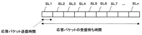
- FIG. 4 is an explanatory diagram illustrating transmission timing of a response packet during a response packet reception wait time according to the embodiment.
- 9 is a flowchart illustrating an operation (operation at the time of receiving an adjacent search packet) of the wireless relay device (subscribed node) according to the embodiment.
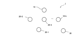
- FIG. 2 is a block diagram showing an example of the overall configuration of the wireless communication system 1 according to the embodiment.
- the wireless communication system 1 includes a wireless communication device 10, a plurality of wireless relay devices 20 (20-1 to 20-k), and a base station 30. Although the number of devices arranged in the wireless communication system 1 is not limited, the wireless communication system 1 of this embodiment has at least one wireless communication device 10 and a plurality of wireless relay devices 20 (20-1 to 20). -K, k ⁇ 2) and one base station 30 will be described.
- a multi-hop network is configured by the wireless relay device 20 and the base station 30 which are wireless communication devices that have already joined the network.
- the wireless communication device 10 the wireless relay device 20, and the base station 30 are also collectively referred to as “nodes”.
- a node (wireless communication device 10) that selects a connection destination to join the network of the wireless communication system 1 is called a “participating node”, and a connected node (wireless relay device 20) that accepts a connection from the participating node. It shall be referred to as "subscribed node”.
- An adjacent node that can directly communicate with a certain node is called an “adjacent node”.
- the communication method (communication medium) between each device (between nodes) in the wireless communication system 1 is not limited. For example, various wireless LAN interface communication methods can be applied.
- the participating node after transmitting the neighbor search packet, changes the operation state from the intermittent operation to the always active continuous operation.
- a node adjacent to the participating node (subscribed node) transmits a response packet by a communication method when intermittent operation is not performed (that is, a method of transmitting only a data packet without transmitting a wake-up packet).
- the participating node selects an adjacent node having the maximum path quality value from the received response packet as a parent node.
- the path quality value represents a communication quality value between itself and the base station 30, and is, for example, a link quality value on a route to the base station 30 (for example, a value calculated based on an RSSI value or a packet loss rate). ).
- the waiting time of the response packet of the participating node is calculated from the probability that all neighboring nodes can transmit a response at the maximum node density assumed in the wireless communication system 1. Further, in consideration of the battery life, the participating node may determine whether to change the operation state to the continuous operation or to operate as the intermittent operation according to the number of trials of the parent node selection.
- the wireless communication device 10 (participating node) and the wireless relay device 20 (subscribed node) will be described. Since the base station 30 has the same configuration as the existing one, the description is omitted.
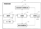
- FIG. 1 is a block diagram showing a functional configuration of the wireless communication device according to the embodiment.
- the wireless communication device 10 includes a communication unit 11, a processing unit 12, an operation state selection unit 13, a response reception waiting time calculation unit 14, a storage unit 15, and a timer unit 16.
- the wireless communication device 10 may be, for example, a computer having a CPU (Central Processing Unit) as an example of a hardware processor and a memory as an example of the storage unit 15.
- the memory stores the wireless communication program, and the CPU loads and executes the wireless communication program, so that the communication unit 11, the processing unit 12, the operation state selection unit 13, the response reception wait time calculation unit 14, and the timer unit 16 Function as
- the wireless communication program may be stored in a non-transitory storage medium such as an SSD or an HDD, and may be installed in the memory from the non-transitory storage medium.
- the wireless communication device 10 may be partially or entirely configured using hardware (for example, a dedicated semiconductor chip or an electric circuit).
- the communication unit 11 has means for transmitting and receiving a wireless signal. For example, the communication unit 11 demodulates a signal received by the antenna and receives a packet included in the signal. Further, the communication unit 11 modulates the packet transmitted from the processing unit 12 to convert the packet into a wireless signal, and starts transmitting the wireless signal using an antenna.
- the processing unit 12 has means for switching the operation state (intermittent operation and continuous operation), generating various packets, and selecting a parent node.
- the processing unit 12 first needs to select a subscribed node in order to participate in the network (wireless communication system 1). At this time, the processing unit 12 selects which operation state of the intermittent operation or the continuous operation is performed. (Hereinafter, also referred to as “operation switching information”) to the operation state selection unit 13.
- the processing unit 12 notifies the response reception wait time calculation unit 14 of the operation switching information acquired from the operation state selection unit 13 and waits for the response reception wait time calculation (acquisition) of the response packet to the adjacent search packet. Request to the time calculation unit 14.
- the processing unit 12 requests the timer unit 16 to set a timer for the response reception waiting time acquired from the response reception waiting time calculation unit 14.
- the processing unit 12 generates an adjacent search packet and requests the communication unit 11 to transmit the packet.
- the adjacent search packet includes the operation state information and the reception waiting time of the response packet.
- the processing unit 12 Upon receiving the response packet from the communication unit 11, the processing unit 12 requests the storage unit 15 to store the response packet received from the adjacent node. Further, when the processing unit 12 receives the notification of the elapse of the reception waiting time from the timer unit 16, the processing unit 12 acquires a response packet from the storage unit 15 and selects a connected node to be connected (selects a parent node).
- the operation state selection unit 13 has means for acquiring the parent selection failure frequency R from the storage unit 15 and calculating operation switching information using the acquired parent selection failure frequency R.
- the parent selection failure count R is the number of retries from the transmission of the neighbor search packet after the transmission of the neighbor search packet, without receiving any response packet during the reception waiting time of the response packet.
- the operation state selection unit 13 notifies the processing unit 12 of the calculated operation switching information.
- the response reception wait time calculating unit 14 has means for calculating a response packet reception wait time in response to a request from the processing unit 12.
- the response reception wait time calculation unit 14 acquires the maximum node density information M (the number of adjacent nodes) of the network system from the storage unit 15 and uses the information.
- the response reception wait time calculation unit 14 notifies the processing unit 12 of the calculated reception wait time.
- the storage unit 15 has means for storing the number of parent selection failures R, the maximum node density information M of the network system, and a response packet (response packet information) transmitted from the adjacent node to the adjacent search packet.
- the maximum node density information M of the network system is determined in advance by a system administrator, for example.
- the timer unit 16 has a means for setting a timer for a time designated by the processing unit 12 and notifying the processing unit 12 of the elapse of the designated time.
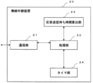
- FIG. 3 is a block diagram showing a functional configuration of the wireless relay device according to the embodiment. 3, the wireless relay device 20 includes a communication unit 21, a processing unit 22, a response transmission waiting time calculation unit 23, and a timer unit 24.
- the wireless relay device 20 may be, for example, a computer having a CPU and a memory as an example of a hardware processor.
- the memory stores the wireless relay program, and the CPU loads and executes the wireless relay program to function as the communication unit 21, the processing unit 22, the response transmission waiting time calculation unit 23, and the timer unit 24.
- the wireless relay program may be stored in a non-transitory storage medium such as an SSD or an HDD, and may be installed in the memory from the non-transitory storage medium.
- the wireless relay device 20 may be partially or entirely configured using hardware (for example, a dedicated semiconductor chip or an electric circuit).
- the communication unit 21 has a unit for transmitting and receiving a wireless signal.
- the communication unit 21 demodulates a signal received by the antenna and receives a packet included in the signal.
- the communication unit 21 modulates the packet sent from the processing unit 22 to convert the packet into a wireless signal, and starts transmitting the wireless signal using an antenna.
- the processing unit 22 When receiving the adjacent search packet from the communication unit 21, the processing unit 22 notifies the response transmission wait time calculation unit 23 of the operation switching information and the reception wait time of the response packet included in the adjacent search packet, and transmits the response packet transmission wait time. Is requested to the response transmission waiting time calculation unit 23.
- the processing unit 22 requests the timer unit 24 to set the transmission wait time acquired from the response transmission wait time calculation unit 23. Further, when receiving the notification of the elapse of the transmission waiting time from the timer unit 24, the processing unit 22 generates a response packet and requests the communication unit 21 to transmit the packet.
- the response packet includes its own path quality value and the RSSI value at the time of receiving the neighbor search packet.
- the response transmission wait time calculation unit 23 has a unit that calculates the response packet transmission wait time using the operation switching information received from the processing unit 22 and the response packet reception wait time.
- the response transmission waiting time calculation unit 23 notifies the processing unit 22 of the calculated transmission waiting time of the response packet.
- the timer unit 24 has a means for setting a timer for a time designated by the processing unit 22 and notifying the processing unit 22 when the designated time has elapsed.
- each device (participating node) until the new wireless communication device 10 (participating node) selects a parent node (subscribed node) from adjacent nodes (network subscribed nodes) to participate in the multi-hop network.
- a parent node subscribed node
- adjacent nodes network subscribed nodes
- step S101 (FIGS. 4 and 5) described later.
- step S102 (FIG. 7) described later.
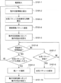
- FIG. 4 is a flowchart illustrating an operation of the wireless communication apparatus (participating node) according to the embodiment (an operation until a joined node is selected).
- the participating node After the power is turned on, the participating node (processing unit 12) issues a request to the operation state selection unit 13 to acquire information (operation switching information) as to whether to switch the operation state during the parent selection operation (S101-1). ).
- the operation state selection unit 13 calculates operation switching information according to the processing of FIG. 5 described below (S101-2).
- the response waiting time calculation unit 14 returns the calculated operation switching information to the processing unit 12.
- the processing unit 12 Upon acquiring the operation switching information, the processing unit 12 notifies the response switching waiting time calculating unit 14 of the operation switching information, and requests to calculate (acquire) the reception waiting time of the response packet with respect to the adjacent search packet transmitted by itself. Is performed (S101-3).
- the response reception wait time calculation unit 14 acquires the maximum node density information M of the network system from the storage unit 15 to calculate the response packet reception wait time.
- the response reception waiting time calculation unit 14 calculates the reception waiting time of the response packet using, for example, the following equation (1).
- the above equation (1) indicates the probability (P) that a subscribed node can transmit a response packet to a participating node.
- P is calculated under the following two preconditions.
- the first precondition is that the timing at which the subscribed node transmits a response packet is selected in units of slots divided into transmission time units of the response packet as shown in FIG.
- the transmission time of the response packet is obtained from the value obtained by dividing the data transmission rate from the size of the response packet and the intermittent operation cycle.
- the operation switching information is “switching” (that is, the parent selecting operation is performed in a continuous operation)
- the intermittent operation cycle is “0”.
- the second precondition is that each node performs data communication in a CSMA / CA (Carrier Sense Multiple Multiple Access / Collision Aviodance) method. That is, even when a certain subscribed node attempts to transmit a response packet at the same timing (slot) as the other x nodes, the response packet can be transmitted with a probability of 1 / (x + 1).
- CSMA / CA Carrier Sense Multiple Multiple Access / Collision Aviodance
- Equation (1) will be described based on the above preconditions.
- N indicates the maximum number of adjacent nodes
- slot indicates the number of slots that can be selected as the response packet transmission timing.
- the term in ⁇ on the right side of the equation (1) indicates that when one subscribed node selects a certain slot for transmitting a response packet, i out of the other N subscribed nodes transmit in the same slot.
- the success rate of the response packet transmission is shown, and P is obtained by calculating the sum of all the possible values of i (that is, from i to N).
- the reception waiting time of the response packet is determined by the value of the slot.
- the value of the slot (slot_n) is calculated so that P becomes 99% or more.
- the response packet reception waiting time finally obtained is “slot_n” ⁇ “response packet transmission time”.
- the response reception wait time calculation unit 14 returns the calculated response packet reception wait time to the processing unit 12.
- the processing unit 12 When the processing unit 12 acquires the reception waiting time of the response packet, the processing unit 12 generates an adjacent search packet, and transmits (eg, broadcasts) the packet via the communication unit 11 (S101-4). At this time, the adjacent search packet includes the operation switching information and the reception waiting time of the response packet.
- the timer unit 16 sets the timer for the reception waiting time of the response packet.
- the processing unit 12 switches the operation state of the node from intermittent operation to continuous operation (S101-5).
- the timer unit 16 sets a timer for the response packet reception wait time, and when a timeout occurs (after the response packet reception wait time elapses), the timer unit 16 shifts to the processing of step S101-9 described below (S101-6).
- the processing unit 12 receives the response packet from the communication unit 11 before the reception waiting time of the response packet elapses, the processing unit 12 receives information on the received response packet (path quality value, RSSI value when receiving the neighbor search packet, and the like). ) And the RSSI value at the time of receiving the response packet are stored in the storage unit 15 (S101-7, S101-8).
- the processing unit 12 When the processing unit 12 receives the notification of the elapse of the response packet reception waiting time from the timer unit 16, the processing unit 12 acquires the received response packet from the storage unit 15. At this time, if no response packet has been received, the processing is re-executed from the processing of S101-2.
- the path quality value when each of the source joined nodes is selected as the connection destination is calculated from the path quality value included in each response packet, the RSSI value of the adjacent search packet, and the RSSI value of the response packet ( S101-9).
- the link quality values of the participating node and the subscribed node are obtained from the two RSSI values (the RSSI value of the adjacent search packet and the RSSI value at the time of receiving the response packet).
- the processing unit 12 selects a subscribed node having the highest path quality value as a connection destination (parent node).
- the processing unit 12 switches the operation state from the continuous operation to the intermittent operation (S101-10).
- FIG. 5 is a flowchart illustrating an operation (a process of calculating operation switching information) of the operation state selection unit according to the embodiment.
- the operation state selection unit 13 Upon receiving the operation switching information acquisition request from the processing unit 12, the operation state selection unit 13 acquires the parent selection failure count R from the storage unit 15 to determine whether to switch the operation state (S101-2A). ).
- the operation state selection unit 13 determines whether the parent selection failure frequency R has been acquired from the storage unit 15 (whether the parent selection failure frequency R exists in the storage unit 15) (S101-2B).
- the operation state selection unit 13 sets the parent selection failure frequency R to “0” (S101-2C). On the other hand, when the parent selection failure frequency R exists, the operation state selection unit 13 adds 1 to the current number (value) of the parent selection failure frequency R (S101-2D).
- a parent selects failure count R is either a calculate (determine) matches one of a n of the following formula (2) (S101-2E).
- n is an integer of 0 or more.
- “switching” occurs when the number of parent selection failures R is, for example, “0”, “2”, “5”, “9”,. Means that the number of times the parent selection operation is performed by “non-switching” is increased by one each time the parent selection operation fails.
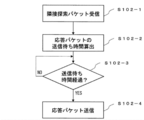
- FIG. 7 is a flowchart illustrating the operation of the wireless relay device (subscribed node) according to the embodiment (the operation at the time of receiving an adjacent search packet).
- the joined node Upon receiving the adjacent search packet via the communication unit 21, the joined node (processing unit 22) notifies the response transmission wait time calculation unit 23 of the operation switching information and the reception wait time of the response packet included in the adjacent search packet. Then, it requests the transmission waiting time calculation unit 23 to calculate (acquire) the transmission waiting time of the response packet (S102-1).
- the response transmission waiting time calculation unit 23 calculates the transmission waiting time of the response packet to be transmitted with respect to the adjacent search packet (S102-2).
- the response transmission wait time calculation unit 23 calculates the number of slots that can be selected as the response packet transmission wait time from the response reception wait time and the operation switching information included in the adjacent search packet.
- the number of slots is obtained as a value obtained by dividing the response reception waiting time by the transmission time of the response packet (when the operation switching information is “non-switching”, the intermittent operation cycle is also included in the transmission time). Next, one slot is randomly selected as the transmission timing of the response packet from the determined number of slots.
- the response transmission wait time calculation unit 23 notifies the processing unit 22 of “selected slot” ⁇ “response packet transmission time” as a response packet transmission wait time.
- the processing unit 22 requests the timer unit 24 to set the transmission waiting time of the response packet to the timer, and upon receiving a timeout notification from the timer unit 24, executes the following processing (S102-3).
- the processing unit 22 generates a response packet, and transmits the packet from the communication unit 21 to the participating node as a destination (S102-4).
- the response packet is transmitted by the communication method in the continuous operation state (the wake-up packet is not transmitted) when the operation switching information is “switching”, and is intermittent operation when the operation switching information is “non-switching”.
- the transmission method is used.
- the participating nodes switch from the intermittent operation to the continuous operation only from the time of transmitting the adjacent search packet to the time of selecting the connected node to which the connection has been made.
- the subscribed node transmits a response packet to the neighbor search packet by the communication method in the continuous operation state.
- this embodiment is characterized in that the reception waiting time and the transmission waiting time of the response packet are obtained from the probability that all adjacent nodes can transmit the response packet at the maximum node density assumed by the network system. Thereby, the participating nodes can receive the response packets from almost all of the adjacent nodes during the reception waiting time of the response packets, so that the parent node having high communication quality can be selected.
- the participating node determines whether the parent selection operation is to be performed in the continuous operation state or the intermittent operation state based on the number of failures in the parent selection operation.
- the feature is to reduce the frequency of implementation in the state. This can improve power saving performance, for example, by preventing wasteful power consumption when there is no subscribed node near the participating node.
- the reception waiting time and the transmission waiting time of the response packet are calculated so that all adjacent subscribed nodes can transmit the response packet (that is, emphasis is placed on the quality of the selected parent node).
- the present invention is not limited to this, and may be calculated from other requirements of the wireless network system.
- the reception waiting time and the transmission waiting time may be determined so as to satisfy the requirements.
- the battery life of the node is important, there is a method of obtaining the battery life requirement. For example, based on the expected number of restarts of the node until the battery life, the average number of adjacent search packet transmissions per boot, the average power consumption in normal times, etc. A method of calculating the time and setting in advance is conceivable.
- the reception waiting time necessary to satisfy the requirements is calculated from the operating time of the node, the remaining battery level, the power consumption during normal times, and the like. There is also a method to determine the value. Furthermore, a method is also conceivable in which the participating nodes statically hold in advance the relationship between the battery life and the reception waiting time at the time of transmitting the adjacent search packet, and determine the reception waiting time using the information.
- the reception wait time of the response packet may differ depending on the participating nodes. The waiting time can be grasped (that is, this value can be used as the maximum value of the response packet transmission waiting time).
- the frequency at which the participating node (the operation state selection unit 13) switches to the continuous operation during the parent selection operation is gradually reduced each time the parent selection operation fails (FIG. 5).
- a method may be considered in which the participating node switches to the intermittent operation from the next trial when the joined node to be connected is not selected even after repeating the parent selecting operation by the continuous operation x times.
- a method is conceivable in which the participating node determines a threshold value of the remaining battery level of the node in advance, and when the remaining battery level is equal to or less than the threshold value, performs a parent selection operation by an intermittent operation.
- the joined node always transmits the response packet to the joining node, but the present invention is not limited to this.
- a method may be considered in which a subscribed node cancels transmission of its own response packet when it detects that a response packet of a node having better communication quality than itself has been transmitted during the response packet transmission waiting time.
- the subscribed node can prevent transmission of useless response packets, and can further reduce the probability of collision of response packets.
- the operation has been described in which the participating node selects the joined node that is the connection destination to wait for the response packet reception waiting time, but the present invention is not limited to this.
- the participating node may select that node as a connection destination.
- the participating node can reduce the time required to select a parent node when the parent selection operation is performed in the intermittent operation state.
Landscapes
- Engineering & Computer Science (AREA)
- Computer Networks & Wireless Communication (AREA)
- Signal Processing (AREA)
- Databases & Information Systems (AREA)
- Mobile Radio Communication Systems (AREA)
Abstract
無線通信システムは、無線通信装置と、複数の無線中継装置と、を有する。無線通信装置は、隣接探索パケットを送信し、隣接探索パケットに対する応答パケットを受信し、隣接探索パケットを送信後、当該無線通信装置の動作状態を間欠動作から連続動作に切り替え、応答パケットの受信待機時間が経過した旨が通知されると、受信待機時間の間に受信した応答パケットの送信元の無線中継装置の中から接続先とする無線中継装置を選択し、接続先を選択後、動作状態を連続動作から間欠動作に切り替える。無線中継装置は、隣接探索パケットを受信し、隣接探索パケットに対する応答パケットを送信し、応答パケットを送信するまでの待ち時間である送信待機時間が経過した旨が通知されると、応答パケットを連続動作における通信方法で送信する。
Description
本開示は、無線通信システム、無線通信装置、及び無線通信プログラムに関し、例えば、無線マルチホップネットワークに適用し得るものである。
複数の無線通信装置(以下、「ノード」とも呼ぶ)と、各ノードを管理する管理装置とを含む無線ネットワークシステムでは、各ノードが管理装置と直接通信できない場合、他のノードが直接通信できないノードに代わって通信を中継するマルチホップネットワークの形態を採用することがある。このマルチホップネットワークの形態により、遠距離にあるノードは、管理装置と通信することが可能となる。
また、無線ネットワークシステムが構築(設置)される環境によっては電源を確保することが難しい場合が多々ある。このような環境では、ノードを電池駆動で動作させることでネットワークを構築することができる。ノードを電池駆動で動作させる場合、ノードは間欠動作することによって電池寿命を向上させることができる。間欠動作とは、ノードが通信を行わない「スリープ状態」と通信を行う「アクティブ状態」とを周期的に切り替える省電力制御技術のことである。
間欠動作の一例として、ノードは基本スリープ状態にあり、一定期間毎にアクティブ状態になって受信するデータが存在するか否か確認を行う。間欠動作するノード間の通信では、データ送信ノードは受信ノードがアクティブ状態の時にデータを送信する必要がある。そのため、データ送信ノードは送信するデータが存在することを示すパケット(以下、「ウェイクアップパケット」とも呼ぶ)を受信ノードのスリープ期間の間だけ送信する。ウェイクアップパケットにはデータの送信タイミングが含まれており、受信ノードはウェイクアップパケットを受信すると、ウェイクアップパケットに含まれるデータ送信タイミングに基づきアクティブ状態になりデータを受信する。このように間欠動作するノード間の通信では、間欠動作しないノード間の通信と比べて、1パケットの送信にスリープ期間(間欠周期)だけ余計に時間を要する。
ところで、マルチホップネットワークに新規参加するノード(以下、「参加ノード」とも呼ぶ)は、ネットワークに参加(加入)するとき、自身が管理装置と直接通信できない場合には、ネットワーク参加要求パケットを参加ノードに代わって中継してもらうノード(以下、「親ノード」とも呼ぶ)を、ネットワークに加入済みのノードの中から選択する。
このような親ノードを選択するために、参加ノードは、自身の周辺ノード(以下、「隣接ノード」とも呼ぶ)を探索するパケット(以下、「隣接ノード探索パケット」とも呼ぶ)をブロードキャス卜する。隣接ノード探索パケットを受信した隣接ノードは、応答パケットを参加ノードに返信する。このとき、隣接ノードの応答パケットの送信タイミングが他の隣接ノードと重なると、パケットが衝突し、参加ノードは応答パケットを受信できない。そのため、各隣接ノードは、衝突を回避するために、隣接ノード探索パケットの受信後にランダム時間だけ待ってから応答パケットを送信する。そして、参加ノードは、受信した応答パケットの中から親ノードを選択する。
親ノードの選択方法には、種々様々な方法が存在すると考えられるが、例えば、受信パケットの受信信号強度(RSSI値)が最も高いノードを選択することが考えられる。参加ノードは、全ての近隣ノードの応答パケットを収集し、その中から親ノードを選択することで、最適な親ノードを決定できる。ただし、全ての隣接ノードが衝突無く応答パケットを送信するためには、周辺のノード密度が高い場合を考慮して応答パケットのランダム待ち時間を十分長く設定する必要がある。また参加ノードも応答パケットのランダム待ち時間の最大値まで待つ必要がある。特にノードが間欠動作する場合、1パケットの送信に間欠周期だけ時間が掛かるため、応答パケットの待ち時間は隣接ノード数と間欠周期に比例して増加する。
以上より、間欠動作するノードで構成される無線ネットワークシステムでは、参加ノードの親ノード選択に時間がかかることが問題となる。
特開2009-302694号公報及び特表2011-523830号公報に記載の技術は、マルチホップネットワークにおける、最適な親ノードの選択方法に関する技術である。特開2009-302694号公報及び特表2011-523830号公報に記載の技術では、参加ノードは、隣接ノードから送信される当該隣接ノードの情報(現在の子ノードの数、管理装置までのホップ数、管理装置までのRTT(Round Trip Time)等)を受信し、最適と思われる隣接ノードを親ノードとして選択する。
また、特表2011-523830号公報では、各ノードはネットワーク参加後にも、隣接ノードとの通信履歴から、パケットロス率やSN比(Signal-to-Noise ratio)を算出し、これらの情報から最適な親ノードを動的に変更する。
そして、特開2015-179923号公報では、データ通信相手(宛先ノード又は中継ノード)の選択方法について開示されている。特開2015-179923号公報に記載の技術では、各ノードは一定間隔で間欠送信信号を発信する。データを送信するノードは、一定期間だけ直接通信範囲にあるノードの間欠送信信号を待ち、受信した間欠送信信号の送信元ノードから、電池残量などを指標に含む無線機選択規則に従い通信相手を選択する。このとき、無線機選択規則の最低条件を満たさないノードは通信相手候補から除外される。
特開2015-179923号公報に記載の技術は、最適な通信相手を選択するのではなく、一定期間の間に受信した間欠送信信号の中から少なくとも一定条件を満たすノードを選ぶという点で特開2009-302694号公報及び特表2011-523830号公報に記載の技術とは異なる。
特開2009-302694号公報及び特表2011-523830号公報に記載の技術は、いずれも最適な親ノードを選択するための指標に関する技術であり、最適な親ノードを選択するためには、全隣接ノードからの応答パケットを待つことが前提となっている。
また、特開2015-179923号公報に記載の技術は、データ送信ノードの間欠送信信号待ち時間を調整するなどで、一定の条件を満たす親ノードを早く選択することができると考えられる。しかしながら、特開2015-179923号公報に記載の技術では、選択される親ノードは必ずしも最適な親ノードではないため、選択された親ノードによっては最適な親ノードを選択した場合と比べて通信品質の劣化が懸念される。
そのため、各ノードが間欠動作するネットワークにおいて、親ノード選択に掛かる時間を削減し、かつ通信品質の高い親ノードを選択できる無線通信システム、無線通信装置、及び無線通信プログラムが望まれている。
第1の態様は、ネットワークへの接続を要求し、間欠動作による無線通信を行う無線通信装置と、該無線通信装置の接続を受付ける複数の無線中継装置と、を有する無線通信システムにおいて、(1)前記無線通信装置は、(1-1)前記無線中継装置を探索するための隣接探索パケットを周囲のネットワークに向けて送信し、前記隣接探索パケットに対する応答パケットを受信する第1の通信部と、(1-2)前記応答パケットの受信待ち時間である受信待機時間を算出する応答受信待ち時間算出部と、(1-3)前記応答受信待ち時間算出部により算出された前記受信待機時間の経過を管理する第1のタイマ部と、(1-4)受信した前記応答パケットを記憶する第1の記憶部と、(1-5)前記隣接探索パケットを送信後、当該無線通信装置の動作状態を間欠動作から連続動作に切り替え、前記第1のタイマ部により前記受信待機時間が経過した旨が通知されると、前記受信待機時間の間に受信した前記応答パケットの送信元の前記無線中継装置の中から接続先とする前記無線中継装置を選択し、接続先を選択後、前記動作状態を連続動作から間欠動作に切り替える第1の処理部と、を有し、(2)前記無線中継装置は、(2-1)前記隣接探索パケットを受信し、前記隣接探索パケットに対する前記応答パケットを送信する第2の通信部と、(2-2)前記応答パケットを送信するまでの待ち時間である送信待機時間を算出する応答送信待ち時間算出部と、(2-3)前記応答送信待ち時間算出部により算出された前記送信待機時間の経過を管理する第2のタイマ部と、(2-4)前記第2のタイマ部により前記送信待機時間が経過した旨が通知されると、前記応答パケットを連続動作における通信方法で送信するように前記第2の通信部を制御する第2の処理部と、を有する。
第2の態様は、ネットワークへの接続を要求し、間欠動作による無線通信を行う無線通信装置において、(1)自身の接続を受付ける無線中継装置を探索するための隣接探索パケットを周囲のネットワークに向けて送信し、前記隣接探索パケットに対する応答パケットを受信する第1の通信部と、(2)前記応答パケットの受信待ち時間である受信待機時間を算出する応答受信待ち時間算出部と、(3)前記応答受信待ち時間算出部により算出された前記受信待機時間の経過を管理する第1のタイマ部と、(4)受信した前記応答パケットを記憶する第1の記憶部と、(5)前記隣接探索パケットを送信後、当該無線通信装置の動作状態を間欠動作から連続動作に切り替え、前記第1のタイマ部により前記受信待機時間が経過した旨が通知されると、前記受信待機時間の間に受信した前記応答パケットの送信元の前記無線中継装置の中から接続先とする前記無線中継装置を選択し、接続先を選択後、前記動作状態を連続動作から間欠動作に切り替える第1の処理部とを有する。
第3の態様の無線通信プログラムは、ネットワークへの接続を要求し、間欠動作による無線通信を行う無線通信装置に搭載されるコンピュータに、(1)自身の接続を受付ける無線中継装置を探索するための隣接探索パケットを周囲のネットワークに向けて送信し、前記隣接探索パケットに対する応答パケットを受信し、(2)前記応答パケットの受信待ち時間である受信待機時間を算出し、(3)算出された前記受信待機時間の経過を管理し、(4)受信した前記応答パケットを記憶し、(5)前記隣接探索パケットを送信後、当該無線通信装置の動作状態を間欠動作から連続動作に切り替え、前記受信待機時間が経過した旨が通知されると、前記受信待機時間の間に受信した前記応答パケットの送信元の前記無線中継装置の中から接続先とする前記無線中継装置を選択し、接続先を選択後、前記動作状態を連続動作から間欠動作に切り替える、処理を実行させる。
本開示によれば、各ノードが間欠動作するネットワークにおいて、親ノード選択に掛かる時間を削減し、かつ通信品質の高い親ノードを選択できる。
(A)主実施形態
以下、本開示に係る無線通信システム、無線通信装置、及び無線通信プログラムの一実施形態を、図面を参照しながら詳述する。
以下、本開示に係る無線通信システム、無線通信装置、及び無線通信プログラムの一実施形態を、図面を参照しながら詳述する。
(A-1)実施形態の構成
(A-1-1)全体構成
図2は、実施形態に係る無線通信システム1の全体構成例を示すブロック図である。
(A-1-1)全体構成
図2は、実施形態に係る無線通信システム1の全体構成例を示すブロック図である。
まず、無線通信システム1の構成について説明する。
無線通信システム1には、無線通信装置10と、複数の無線中継装置20(20-1~20-k)と、基地局30とが配置されている。無線通信システム1に配置される各装置の数は限定されないが、この実施形態の無線通信システム1では、少なくとも1個の無線通信装置10と、複数個の無線中継装置20(20-1~20-k、k≧2)と、1個の基地局30とが配置されているものとして説明する。
また、無線通信システム1では、既にネットワークに加入済みの無線通信装置である無線中継装置20及び基地局30によりマルチホップネットワークが構成されているものとする。以下では、無線通信装置10、無線中継装置20、及び基地局30のことを、総称して「ノード」とも呼ぶものとする。また、無線通信システム1のネットワークへ参加するために接続先を選択するノード(無線通信装置10)を「参加ノード」と呼び、参加ノードからの接続を受け付ける被接続ノード(無線中継装置20)を「加入済みノード」と呼ぶものとする。また、あるノードと直接通信可能な隣接するノードを「隣接ノード」と呼ぶものとする。無線通信システム1内の各装置間(ノード間)の通信方式(通信媒体)については限定されないが、例えば、種々の無線LANインタフェースの通信方式を適用することができる。
次に、この実施形態の無線通信システム1の特徴の概要を述べる。
この実施形態では、参加ノードは、隣接探索パケットを送信後、間欠動作から常にアクティブな連続動作に動作状態を変更する。参加ノードの隣接ノード(加入済みノード)は、間欠動作しない場合の通信方法(つまり、ウェイクアップパケットを送信せずデータパケットのみを送信する方法)で応答パケットを送信する。参加ノードは、一定時間応答パケットを待った後、受信した応答パケットから最大のパス品質値を持つ隣接ノードを親ノードとして選択する。
なお、パス品質値とは、自身と基地局30との間の通信品質値を表し、例えば基地局30までの経路上のリンク品質値(例えばRSSI値やパケットロス率を基に算出される値)の和で表される。また、参加ノードの応答パケットの待ち時間は、無線通信システム1で想定される最大のノード密度において、全近隣ノードが応答を送信できる確率から算出する。さらに、電池寿命を考慮して、参加ノードは、親ノード選択の試行回数に応じて動作状態を連続動作に変更するか間欠動作のまま動作するか判断してもよい。
次に、無線通信装置10(参加ノード)及び無線中継装置20(加入済みノード)の詳細構成について述べる。基地局30は既存の構成と同様のため、説明を省略する。
(A-1-2)無線通信装置10(参加ノード)の詳細な構成
図1は、実施形態に係る無線通信装置の機能的構成について示すブロック図である。図1において、無線通信装置10は、通信部11、処理部12、動作状態選択部13、応答受信待ち時間算出部14、記憶部15、及びタイマ部16を有する。
図1は、実施形態に係る無線通信装置の機能的構成について示すブロック図である。図1において、無線通信装置10は、通信部11、処理部12、動作状態選択部13、応答受信待ち時間算出部14、記憶部15、及びタイマ部16を有する。
無線通信装置10は、例えば、ハードウェアのプロセッサの一例であるCPU(Central Processing Unit)及び、記憶部15の一例であるメモリを有するコンピュータであってもよい。メモリは、無線通信プログラムを記憶し、CPUは、無線通信プログラムをロードして実行することで、通信部11、処理部12、動作状態選択部13、応答受信待ち時間算出部14及びタイマ部16として機能する。
無線通信プログラムは、SSD、HDDなどの非一時的記憶媒体に記憶されていて、非一時的記憶媒体からメモリにインストールされてもよい。無線通信装置10は、一部又は全部をハードウェア(例えば、専用の半導体チップや電気回路等)を用いて構成するようにしてもよい。
通信部11は、無線信号を送受信する手段を有する。例えば、通信部11はアンテナで受信した信号の復調とその信号に含まれるパケットの受信を行う。また、通信部11は、処理部12から送られてきたパケットを変調して無線信号に変換し、アンテナを用いて当該無線信号の送信を開始する。
処理部12は、動作状態(間欠動作と連続動作)の切り替え、各種パケットの生成、親ノードの選択を行う手段を有する。
処理部12は、まず、ネットワーク(無線通信システム1)に参加するために加入済みノードを選択する必要があるが、その際、自身が間欠動作と連続動作のどちらの動作状態になるかを選択するための情報(以下、「動作切替情報」とも呼ぶ)を、動作状態選択部13に要求する。
続いて、処理部12は、動作状態選択部13から取得した動作切替情報を応答受信待ち時間算出部14に通知し、隣接探索パケットに対する応答パケットの受信待ち時間の算出(取得)を応答受信待ち時間算出部14に要求する。処理部12は、応答受信待ち時間算出部14から取得した応答受信待ち時間分のタイマのセットをタイマ部16に要求する。
また、処理部12は、隣接探索パケットを生成し通信部11に当該パケットの送信を要求する。なお、隣接探索パケットには動作状態情報と応答パケットの受信待ち時間が含まれる。
処理部12は、通信部11から応答パケットを受信すると、記憶部15に隣接ノードから受信した応答パケットの保存を要求する。さらに、処理部12は、タイマ部16から受信待ち時間経過の通知を受信すると、記憶部15から応答パケットを取得し、接続する加入済みノードを選択(親ノードを選択)する。
動作状態選択部13は、記憶部15から親選択失敗回数Rを取得し、取得した親選択失敗回数Rを使用して動作切替情報を算出する手段を有する。親選択失敗回数Rとは、隣接探索パケットを送信してから応答パケットの受信待ち時間に1つの応答パケットも受信せず、隣接探索パケットの送信からリトライした回数である。動作状態選択部13は、算出した動作切替情報を処理部12に通知する。
応答受信待ち時間算出部14は、処理部12からの要求に応じて、応答パケットの受信待ち時間を算出する手段を有する。応答受信待ち時間算出部14は、ネットワークシステムの最大ノード密度情報M(隣接ノード数)を記憶部15から取得して利用する。応答受信待ち時間算出部14は、算出した受信待ち時間を処理部12に通知する。
記憶部15は、親選択失敗回数R、ネットワークシステムの最大ノード密度情報M、及び隣接探索パケットに対して隣接ノードから送信された応答パケット(応答パケットの情報)を保存する手段を有する。ネットワークシステムの最大ノード密度情報Mは、例えば、システムの管理者が事前に定める。
タイマ部16は、処理部12から指定された時間のタイマをセットし、指定された時間が経過するとその旨を処理部12に通知する手段を有する。
(A-1-3)無線中継装置20(加入済みノード)の詳細な構成
図3は、実施形態に係る無線中継装置の機能的構成について示すブロック図である。図3において、無線中継装置20は、通信部21、処理部22、応答送信待ち時間算出部23、及びタイマ部24を有する。
図3は、実施形態に係る無線中継装置の機能的構成について示すブロック図である。図3において、無線中継装置20は、通信部21、処理部22、応答送信待ち時間算出部23、及びタイマ部24を有する。
無線中継装置20は、例えば、ハードウェアのプロセッサの一例であるCPU及びメモリを有するコンピュータであってもよい。メモリは、無線中継プログラムを記憶し、CPUは、無線中継プログラムをロードして実行することで、通信部21、処理部22、応答送信待ち時間算出部23及びタイマ部24として機能する。
無線中継プログラムは、SSD、HDDなどの非一時的記憶媒体に記憶されていて、非一時的記憶媒体からメモリにインストールされてもよい。無線中継装置20は、一部又は全部をハードウェア(例えば、専用の半導体チップや電気回路等)を用いて構成するようにしてもよい。
通信部21は、無線信号を送受信する手段を有する。例えば、通信部21はアンテナで受信した信号の復調とその信号に含まれるパケットの受信を行う。また、通信部21は、処理部22から送られてきたパケットを変調して無線信号に変換し、アンテナを用いて当該無線信号の送信を開始する。
処理部22は、通信部21から隣接探索パケットを受信すると、隣接探索パケットに含まれる動作切替情報と応答パケットの受信待ち時間を応答送信待ち時間算出部23に通知し、応答パケットの送信待ち時間の算出を応答送信待ち時間算出部23に要求する。処理部22は、応答送信待ち時間算出部23から取得した送信待ち時間のセットをタイマ部24に要求する。また、処理部22は、タイマ部24から送信待ち時間経過の通知を受信すると、応答パケットを生成し通信部21に当該パケットの送信を要求する。応答パケットには、自身のパス品質値と隣接探索パケット受信時のRSSI値が含まれる。
応答送信待ち時間算出部23は、処理部22から受信した動作切替情報および応答パケットの受信待ち時間を使用して、応答パケットの送信待ち時間を算出する手段を有する。応答送信待ち時間算出部23は、算出した応答パケットの送信待ち時間を処理部22に通知する。
タイマ部24は、処理部22から指定された時間のタイマをセットし、指定された時間が経過するとその旨を処理部22に通知する手段を有する。
(A-2)実施形態の動作
次に、以上のような構成を有する実施形態の無線通信システム1の動作を説明する。
次に、以上のような構成を有する実施形態の無線通信システム1の動作を説明する。
以下では、新規の無線通信装置10(参加ノード)が、マルチホップネットワークに参加するために、隣接ノード(ネットワーク加入済みノード)の中から親ノード(加入済みノード)を選択するまでの各装置(参加ノード、加入済みノード)の動作を図4~図7を用いて説明する。
参加ノードの動作は、後述するステップS101(図4、図5)である。また、加入済みノードの動作は、後述するステップS102(図7)である。
[ステップS101:参加ノードの動作]
図4は、実施形態に係る無線通信装置(参加ノード)の動作(加入済みノードを選択するまでの動作)を示すフローチャートである。
図4は、実施形態に係る無線通信装置(参加ノード)の動作(加入済みノードを選択するまでの動作)を示すフローチャートである。
参加ノード(処理部12)は、電源投入後、動作状態選択部13に対して、親選択動作時に動作状態を切り替えるかの情報(動作切替情報)を取得するための要求を行う(S101-1)。
動作状態選択部13は、後述する図5の処理に従い動作切替情報を算出する(S101-2)。応答待ち時間算出部14は、算出した動作切替情報を処理部12に返信する。
処理部12は、動作切替情報を取得すると、応答受信待ち時間算出部14に動作切替情報を通知し、自身が送信する隣接探索パケットに対する応答パケットの受信待ち時間を算出(取得)するための要求を行う(S101-3)。
詳細には、応答受信待ち時間算出部14は、応答パケットの受信待ち時間を算出するために、記憶部15からネットワークシステムの最大ノード密度情報Mを取得する。
次に、応答受信待ち時間算出部14は、応答パケットの受信待ち時間を、例えば、以下の(1)式を用いて算出する。

上記(1)式は、加入済みノードが参加ノードに応答パケットを送信できる確率(P)を示している。Pは、以下の2つの前提条件のもとで算出される。
1つ目の前提条件は、加入済みノードが応答パケットを送信するタイミングを、図6に示すような応答パケットの送信時間単位に区切ったスロット単位で選択することである。ここで応答パケットの送信時間は、応答パケットのサイズからデータ送信レートを除算した値と間欠動作周期から求まる。動作切替情報が「切替」(つまり連続動作で親選択動作を実行する)の場合は、間欠動作周期は「0」である。
2つ目の前提条件は、各ノードは、CSMA/CA(Carrier Sense Multiple Access/Collision Avoidance)方式でデータ通信することである。つまり、ある加入済みノードが他のx台のノードと同じタイミング(スロット)で応答パケットを送信しようとした場合でも、1/(x+1)の確率で応答パケットを送信できる。
以上の前提条件をもとに(1)式の説明を行う。(1)式のNは最大の隣接ノード数を示し、slotは応答パケットの送信タイミングとして選択され得るスロット数を示している。(1)式の右辺のΣの中の項は、ある加入済みノードが応答パケット送信のためにあるスロットを選択した場合に、他のN台の加入済みノードのうちi台が同じスロットで送信を試みた場合の応答パケット送信成功率を示しており、これをiが取り得る全ての値(つまりiからNまで)で計算した和を計算することでPが求まる。
応答パケットの受信待ち時間は、slotの値によって決まり、ここではPが99%以上となるようにslotの値(slot_n)を算出する。最終的に求める応答パケットの受信待ち時間は、「slot_n」×「応答パケット送信時間」となる。
応答受信待ち時間算出部14は、算出した応答パケットの受信待ち時間を処理部12に返信する。
処理部12は、応答パケットの受信待ち時間を取得すると、隣接探索パケットを生成し、通信部11を介して当該パケットを送信(例えばブロードキャスト)する(S101-4)。この際、隣接探索パケットには動作切替情報と応答パケットの受信待ち時間を含める。タイマ部16は、応答パケットの受信待ち時間だけタイマをセットする。
また、処理部12は、動作切替情報が「切替」の場合、ノードの動作状態を間欠動作から連続動作に切り替える(S101-5)。
タイマ部16は、応答パケットの受信待ち時間だけタイマをセットし、タイムアウトすると(応答パケットの受信待ち時間が経過すると)、後述するステップS101-9の処理に移行する(S101-6)。
一方、処理部12は、応答パケットの受信待ち時間が経過するまでの間に通信部11から応答パケットを受信すると、受信した応答パケットの情報(パス品質値、隣接探索パケット受信時のRSSI値等)と、応答パケット受信時のRSSI値とを記憶部15に保存する(S101-7、S101-8)。
処理部12は、タイマ部16から応答パケットの受信待ち時間経過の通知を受信すると、記憶部15から受信した応答パケットを取得する。このとき、応答パケットを1つも受信しなかった場合、S101-2の処理から再実行する。それ以外の場合、各応答パケットに含まれるパス品質値、隣接探索パケットのRSSI値、応答パケットのRSSI値から送信元の各加入済みノードを接続先に選択した場合のパス品質値を計算する(S101-9)。ここで参加ノードと加入済みノードのリンク品質値は、上記2つのRSSI値(隣接探索パケットのRSSI値、応答パケット受信時のRSSI値)から求める。処理部12は、最もパス品質値の高い加入済みノードを接続先(親ノード)として選択する。
そして、処理部12は、現在の動作状態が連続動作の場合、動作状態を連続動作から間欠動作に切り替える(S101-10)。
次に、先述のステップS101-2の処理(動作切替情報の算出)の補足説明を行う。図5は、実施形態に係る動作状態選択部の動作(動作切替情報を算出する処理)を示すフローチャートである。
動作状態選択部13は、処理部12から動作切替情報の取得要求を受けると、動作状態を切り替えるか否かを決定するために、記憶部15から親選択失敗回数Rを取得する(S101-2A)。
動作状態選択部13は、記憶部15から親選択失敗回数Rを取得できたか否か(記憶部15に親選択失敗回数Rが存在するか否か)判定を行う(S101-2B)。
動作状態選択部13は、記憶部15に親選択失敗回数Rが存在しない場合(つまり初めて試行する場合)には、親選択失敗回数Rに「0」を設定する(S101-2C)。一方、動作状態選択部13は、親選択失敗回数Rが存在する場合、親選択失敗回数Rの現在の回数(値)に1だけ加算する(S101-2D)。
次に、動作状態選択部13は、親選択失敗回数Rが下記(2)式のいずれかのanと一致するかを計算(判定)する(S101-2E)。ここで、nは0以上の整数である。

動作状態選択部13は、親選択失敗回数Rが上記(2)式のいずれかのanと一致した場合には、動作切替情報を「切替」と選択し(S101-2F)、一致しない場合には、動作切替情報を「非切替」と選択する(S101-2G)。
上記(2)式より、「切替」になるのは親選択失敗回数Rが、例えば、「0」、「2」、「5」、「9」、・・・の場合であり、「切替」で親選択動作を失敗する度に「非切替」で親選択動作を行う回数を1ずつ増やしていくことを意味している。
[ステップS102:加入済みノードの動作]
図7は、実施形態に係る無線中継装置(加入済みノード)の動作(隣接探索パケット受信時の動作)を示すフローチャートである。
図7は、実施形態に係る無線中継装置(加入済みノード)の動作(隣接探索パケット受信時の動作)を示すフローチャートである。
加入済みノード(処理部22)は、通信部21を介して隣接探索パケットを受信すると、隣接探索パケットに含まれる、動作切替情報及び応答パケットの受信待ち時間を応答送信待ち時間算出部23に通知し、応答パケットの送信待ち時間の算出(取得)を応答送信待ち時間算出部23に要求する(S102-1)。
応答送信待ち時間算出部23は、隣接探索パケットに対して送信する応答パケットの送信待ち時間を算出する(S102-2)。
詳細には、応答送信待ち時間算出部23は、隣接探索パケットに含まれる応答受信待ち時間及び動作切替情報から、応答パケットの送信待ち時間として選択し得るスロット数を算出する。このスロット数は、応答受信待ち時間を応答パケットの送信時間(動作切替情報が「非切替」の場合は間欠動作周期も送信時間に含む)で除算した値として求められる。次に、求めたスロット数の中から応答パケットの送信タイミングとしてランダムに1スロット選択する。
応答送信待ち時間算出部23は、「選択したスロット」×「応答パケットの送信時間」を、応答パケットの送信待ち時間として処理部22に通知する。
処理部22は、タイマ部24に応答パケットの送信待ち時間をタイマにセットするよう要求し、タイマ部24からタイムアウトの通知を受けると、次の処理を実行する(S102-3)。
処理部22は、応答パケットを生成し、参加ノードを宛先として通信部21から当該パケットを送信する(S102-4)。この際、応答パケットは、動作切替情報が「切替」の場合は連続動作状態での通信方法(ウェイクアップパケットを送信しない)で送信し、動作切替情報が「非切替」の場合は間欠動作での通信方法で送信する。
(A-3)実施形態の効果
この実施形態によれば、以下の効果を奏する。
この実施形態によれば、以下の効果を奏する。
無線通信システム1(各ノードが間欠動作するネットワーク)では、参加ノードは、隣接探索パケットを送信してから接続先の加入済みノードを選択するまでの間だけ間欠動作から連続動作に切り替える。また、加入済みノードは、連続動作状態の通信方法により、隣接探索パケットに対する応答パケットを送信する。これにより、参加ノードが全ての隣接の加入済みノードから応答パケットを受信するまでの時間を削減できるため、親ノード選択にかかる時間を削減できる。
また、この実施形態では、応答パケットの受信待ち時間と送信待ち時間を、ネットワークシステムが想定する最大ノード密度で全隣接ノードが応答パケットを送信できる確率から求めることに特徴がある。これにより、参加ノードは応答パケットの受信待ち時間の間にほぼ全ての隣接ノードから応答パケットを受信することができるため、通信品質の高い親ノードを選択することができる。
そして、この実施形態では、参加ノードが親選択動作の失敗回数を基に、親選択動作を連続動作状態と間欠動作状態のどちらで実施するかを判断し、さらに失敗回数が多くなるにつれて連続動作状態で実施する頻度を減らしていくことに特徴がある。これにより、例えば、参加ノードの周辺に加入済みノードが存在しない場合などに無駄に電力を消費してしまうのを防ぐなど、省電力性能を向上できる。
(B)他の実施形態
本開示は、上記実施形態に限定されるものではなく、以下に例示するような変形実施形態も挙げることができる。
本開示は、上記実施形態に限定されるものではなく、以下に例示するような変形実施形態も挙げることができる。
(B-1)上記実施形態では、応答パケットの受信待ち時間と送信待ち時間を、全ての隣接の加入済みノードが応答パケットを送信できるように算出(つまり選択される親ノードの品質を重視)する例を示したが、これに限定するものではなく無線ネットワークシステムの他の要件から算出してもよい。
例えば、親ノード選択時間が要件に含まれるようなシステムでは、要件を満たすように受信待ち時間と送信待ち時間を決定してもよい。また、ノードの電池寿命が重要なシステムでは、電池寿命要件から求める方法もある。例えば、参加ノードが電池寿命までのノードの予想再起動回数、1回の起動での平均隣接探索パケット送信回数、通常時の平均消費電力量などから、電池寿命要件を満たすために必要な受信待ち時間を算出し、事前設定する方法が考えられる。
また、例えば、参加ノードが隣接探索パケットを送信する度に、ノードのこれまでの稼働時間、電池残量、通常時の消費電力量などから要件を満たすために必要な受信待ち時間を都度計算して求める方法も考えられる。さらに、参加ノードが事前に隣接探索パケット送信時の電池寿命と受信待ち時間の関係を内部に静的に保持しておき、その情報を用いて受信待ち時間を決める方法も考えられる。電池寿命要件から受信待ち時間を求める場合、参加ノードによって応答パケットの受信待ち時間が異なる場合があるため、隣接探索パケットに受信待ち時間を含めて送信することで、加入済みノードは参加ノードの応答待ち時間を把握することができる(つまり、この値を応答パケットの送信待ち時間の最大値に使用できる)。
(B-2)上記実施形態では、参加ノード(動作状態選択部13)が親選択動作の間に連続動作に切り替える頻度を、親選択動作に失敗する度に除々に減らしていく例(図5の処理)について述べたが、これに限定されるものではない。例えば、参加ノードは連続動作による親選択動作をx回繰り返しても接続先の加入済みノードが選択されない場合に、次の試行からは間欠動作に切り替える方法が考えられる。また、参加ノードはノードの電池残量の閾値を予め定め、電池残量が閾値以下の場合には間欠動作で親選択動作する方法も考えられる。
(B-3)上記実施形態では、加入済みノードが応答パケットを送信するまでの間に複数の隣接探索パケットを受信した場合について言及しなかったが、このような場合に、複数の参加ノードへの応答をまとめて1つの応答パケットとして送信する方法が考えられる。この場合、加入済みノードは各参加ノードのアドレスと隣接探索パケットのRSSI値の組を応答パケットに含め、ブロードキャストする。この方法により、応答パケットの送信回数を削減できるため、加入済みノードの消費電力の削減やネットワークの輻輳抑制が期待される。
(B-4)上記実施形態では、加入済みノードは必ず参加ノードに応答パケットを送信していたが、これに限定するものではない。例えば、加入済みノードは、応答パケット送信待ち時間の間に、自分より通信品質の良いノードの応答パケットが送信されたのを検出した場合に、自身の応答パケットの送信を取りやめる方法が考えられる。これにより、加入済みノードは、無駄な応答パケットが送信されるのを防ぎ、応答パケットの衝突確率をより低下させることができる。
(B-5)上記実施形態では、参加ノードが応答パケットの受信待ち時間だけ待ち接続先の加入済みノードを選択する動作について示したが、これに限定するものではない。例えば、参加ノードは、ある一定のパス品質を満たす加入済みノードの応答パケットを受信した時点でそのノードを接続先に選択してもよい。これにより、参加ノードは特に間欠動作状態で親選択動作を実施する場合の親ノード選択にかかる時間を削減できる。
(B-6)上記実施形態では、参加ノードが応答パケットの受信待ち時間を都度計算する例を示したが、事前計算で設定できる場合には、事前計算した応答パケットの受信待ち時間を予め記憶部15に保存しておく方法も考えられる。
本願は2018年8月15日出願の日本出願第2018-152863号の優先権を主張すると共に、その全文を参照により本明細書に援用する。
Claims (14)
- ネットワークへの接続を要求し、間欠動作による無線通信を行う無線通信装置と、該無線通信装置の接続を受付ける複数の無線中継装置とを有する無線通信システムにおいて、
前記無線通信装置は、
前記無線中継装置を探索するための隣接探索パケットを周囲のネットワークに向けて送信し、前記隣接探索パケットに対する応答パケットを受信する第1の通信部と、
前記応答パケットの受信待ち時間である受信待機時間を算出する応答受信待ち時間算出部と、
前記応答受信待ち時間算出部により算出された前記受信待機時間の経過を管理する第1のタイマ部と、
受信した前記応答パケットを記憶する第1の記憶部と、
前記隣接探索パケットを送信後、当該無線通信装置の動作状態を間欠動作から連続動作に切り替え、前記第1のタイマ部により前記受信待機時間が経過した旨が通知されると、前記受信待機時間の間に受信した前記応答パケットの送信元の前記無線中継装置の中から接続先とする前記無線中継装置を選択し、接続先を選択後、前記動作状態を連続動作から間欠動作に切り替える第1の処理部と、
を有し、
前記無線中継装置は、
前記隣接探索パケットを受信し、前記隣接探索パケットに対する前記応答パケットを送信する第2の通信部と、
前記応答パケットを送信するまでの待ち時間である送信待機時間を算出する応答送信待ち時間算出部と、
前記応答送信待ち時間算出部により算出された前記送信待機時間の経過を管理する第2のタイマ部と、
前記第2のタイマ部により前記送信待機時間が経過した旨が通知されると、前記応答パケットを連続動作における通信方法で送信するように前記第2の通信部を制御する第2の処理部と、
を有する、
無線通信システム。 - 前記無線通信装置は、前記隣接探索パケットを送信後、前記動作状態を連続動作状態に切り替えるか否かを判断する動作状態選択部をさらに有し、
前記第1の処理部は、前記動作状態選択部で前記動作状態を切り替えないと判断された場合には、前記動作状態を間欠動作のままで、接続先とする前記無線中継装置を選択する一連の処理を実施し、
前記隣接探索パケットには、前記動作状態が間欠動作であることを示す動作情報が含まれ、
前記第2の処理部は、前記動作情報に基づき間欠動作の通信方式で前記応答パケットを送信するように前記第2の通信部を制御する
請求項1に記載の無線通信システム。 - 前記動作状態選択部は、接続先とする前記無線中継装置を選択する一連の動作の失敗回数が多くなるほど、前記動作状態を連続動作状態に切り替える頻度を少なくする、
請求項2に記載の無線通信システム。 - 前記動作状態選択部は、所定の回数だけ接続先とする前記無線中継装置を選択する一連の動作が失敗すると、前記動作状態を連続動作状態に切り替えない、
請求項2に記載の無線通信システム。 - 前記動作状態選択部は、前記隣接探索パケットの送信時の当該無線通信装置の電池残量が所定の閾値を下回っていた場合には、前記動作状態を連続動作に切り替えない、
請求項2に記載の無線通信システム。 - 前記受信待機時間、及び前記送信待機時間は、ネットワークの最大ノード密度における隣接ノード数を使用して算出される、
請求項1~5のいずれか1項に記載の無線通信システム。 - 前記受信待機時間、及び前記送信待機時間は、前記最大ノード密度において、前記無線中継装置が前記応答パケットを送信できる確率の値から算出される、
請求項6に記載の無線通信システム。 - 前記受信待機時間、及び前記送信待機時間は、当該無線通信システムの時間的要件に基づいて算出される、
請求項1~請求項5のいずれか1項に記載の無線通信システム。 - 前記受信待機時間、及び前記送信待機時間は、当該無線通信システムとして必要とされる電池寿命の要件から算出される、
請求項1~請求項5のいずれか1項に記載の無線通信システム。 - 前記第1の処理部は、前記第1のタイマ部により前記受信待機時間が経過した旨が通知される前であっても、所定の通信品質を満たす前記無線中継装置の前記応答パケットを受信した時点で、接続先とする前記無線中継装置を選択する、
請求項1~請求項9のいずれか1項に記載の無線通信システム。 - 前記無線通信装置は複数であり、
前記無線中継装置は、受信した前記隣接探索パケットを記憶する第2の記憶部をさらに有し、
第2の処理部は、前記送信待機時間の間に受信した、複数の前記隣接探索パケットに対する前記応答パケットを1つの前記応答パケットとして送信するように制御する、
請求項1~請求項10のいずれか1項に記載の無線通信システム。 - 前記第2の通信部は、他の前記無線中継装置が送信した前記応答パケットを傍受し、
前記第2の処理部は、自身より通信品質の良い他の前記無線中継装置の前記応答パケットを受信した場合には、前記応答パケットの送信を取り止める、
請求項1~請求項11のいずれか1項に記載の無線通信システム。 - ネットワークへの接続を要求し、間欠動作による無線通信を行う無線通信装置において、
自身の接続を受付ける無線中継装置を探索するための隣接探索パケットを周囲のネットワークに向けて送信し、前記隣接探索パケットに対する応答パケットを受信する第1の通信部と、
前記応答パケットの受信待ち時間である受信待機時間を算出する応答受信待ち時間算出部と、
前記応答受信待ち時間算出部により算出された前記受信待機時間の経過を管理する第1のタイマ部と、
受信した前記応答パケットを記憶する第1の記憶部と、
前記隣接探索パケットを送信後、当該無線通信装置の動作状態を間欠動作から連続動作に切り替え、前記第1のタイマ部により前記受信待機時間が経過した旨が通知されると、前記受信待機時間の間に受信した前記応答パケットの送信元の前記無線中継装置の中から接続先とする前記無線中継装置を選択し、接続先を選択後、前記動作状態を連続動作から間欠動作に切り替える第1の処理部と、
を有する無線通信装置。 - ネットワークへの接続を要求し、間欠動作による無線通信を行う無線通信装置に搭載されるコンピュータに、
自身の接続を受付ける無線中継装置を探索するための隣接探索パケットを周囲のネットワークに向けて送信し、前記隣接探索パケットに対する応答パケットを受信し、
前記応答パケットの受信待ち時間である受信待機時間を算出し、
算出された前記受信待機時間の経過を管理し、
受信した前記応答パケットを第1の記憶部に記憶し、
前記隣接探索パケットを送信後、当該無線通信装置の動作状態を間欠動作から連続動作に切り替え、前記受信待機時間が経過した旨が通知されると、前記受信待機時間の間に受信した前記応答パケットの送信元の前記無線中継装置の中から接続先とする前記無線中継装置を選択し、接続先を選択後、前記動作状態を連続動作から間欠動作に切り替える
処理を実行させる無線通信プログラム。
Applications Claiming Priority (2)
| Application Number | Priority Date | Filing Date | Title |
|---|---|---|---|
| JP2018-152863 | 2018-08-15 | ||
| JP2018152863A JP7119750B2 (ja) | 2018-08-15 | 2018-08-15 | 無線通信システム、無線通信装置、及び無線通信プログラム |
Publications (1)
| Publication Number | Publication Date |
|---|---|
| WO2020035979A1 true WO2020035979A1 (ja) | 2020-02-20 |
Family
ID=69525332
Family Applications (1)
| Application Number | Title | Priority Date | Filing Date |
|---|---|---|---|
| PCT/JP2019/020332 Ceased WO2020035979A1 (ja) | 2018-08-15 | 2019-05-22 | 無線通信システム、無線通信装置、及び無線通信プログラム |
Country Status (2)
| Country | Link |
|---|---|
| JP (1) | JP7119750B2 (ja) |
| WO (1) | WO2020035979A1 (ja) |
Citations (3)
| Publication number | Priority date | Publication date | Assignee | Title |
|---|---|---|---|---|
| JP2008259165A (ja) * | 2006-09-01 | 2008-10-23 | Matsushita Electric Ind Co Ltd | 無線通信方法および無線通信装置 |
| JP2010239357A (ja) * | 2009-03-31 | 2010-10-21 | Oki Electric Ind Co Ltd | 無線通信装置及び通信制御方法 |
| JP2017152906A (ja) * | 2016-02-24 | 2017-08-31 | 沖電気工業株式会社 | 無線通信システム、無線通信装置、無線通信プログラム、無線中継装置、及び無線中継プログラム |
-
2018
- 2018-08-15 JP JP2018152863A patent/JP7119750B2/ja active Active
-
2019
- 2019-05-22 WO PCT/JP2019/020332 patent/WO2020035979A1/ja not_active Ceased
Patent Citations (3)
| Publication number | Priority date | Publication date | Assignee | Title |
|---|---|---|---|---|
| JP2008259165A (ja) * | 2006-09-01 | 2008-10-23 | Matsushita Electric Ind Co Ltd | 無線通信方法および無線通信装置 |
| JP2010239357A (ja) * | 2009-03-31 | 2010-10-21 | Oki Electric Ind Co Ltd | 無線通信装置及び通信制御方法 |
| JP2017152906A (ja) * | 2016-02-24 | 2017-08-31 | 沖電気工業株式会社 | 無線通信システム、無線通信装置、無線通信プログラム、無線中継装置、及び無線中継プログラム |
Non-Patent Citations (1)
| Title |
|---|
| TSUCHIE, KOTA, YAO, TAKETSUGU, TERANISHI, YUUICHI: "Field Evaluation of Parent Node Discovery Time Reduction Algorithm for Low- Power Wireless Multihop Networks", IEICE TECHNICAL REPORT, vol. 117, no. 460, 1 March 2018 (2018-03-01), pages 213 - 218 * |
Also Published As
| Publication number | Publication date |
|---|---|
| JP2020028062A (ja) | 2020-02-20 |
| JP7119750B2 (ja) | 2022-08-17 |
Similar Documents
| Publication | Publication Date | Title |
|---|---|---|
| CN110661870B (zh) | 一种hplc通信组网的方法、装置、存储介质和电子设备 | |
| US10129731B2 (en) | Neighbor discovery and neighbor selection of mesh network devices in a mesh network | |
| JP6801191B2 (ja) | 無線通信システム、無線通信装置、及び無線通信プログラム | |
| US10219142B2 (en) | Neighbor discovery and neighbor selection of mesh network devices in a mesh network | |
| US9220050B2 (en) | Mesh network defragmentation | |
| US20180368048A1 (en) | Radio communication system, radio relay device, and storage medium | |
| CN103108371B (zh) | 单天线多信道认知无线传感器网络路由控制方法 | |
| US10178652B2 (en) | Method for operating a network element of a wireless communication network and network element | |
| WO2010105404A1 (zh) | 确定传输模式的方法、装置及终端 | |
| EP2781074A1 (en) | Communication protocol for energy-harvesting devices | |
| CN110351791B (zh) | 一种系统信息的接收处理方法、装置及用户终端 | |
| CN111345105B (zh) | 网格网络中的网络节点和方法 | |
| JPWO2018150514A1 (ja) | 無線アドホックネットワークにおける通信端末、通信方法及び通信プログラム | |
| JP2008228180A (ja) | 無線装置 | |
| US20200367124A1 (en) | Synchronization Of Client And Access Point During Channel Switch In Wireless Communications | |
| JP2019121906A (ja) | 無線通信装置、無線通信方法およびコンピュータプログラム | |
| JP7119750B2 (ja) | 無線通信システム、無線通信装置、及び無線通信プログラム | |
| JP2019022112A (ja) | 無線中継装置、無線中継プログラム、無線通信装置、無線通信プログラム及び無線通信システム | |
| CN109429294B (zh) | 通信方法、基站、中继节点和具有存储性能的装置 | |
| RU2716836C2 (ru) | Способ передачи данных услуги и передающее устройство | |
| Spachos et al. | Performance comparison of opportunistic routing schemes in wireless sensor networks | |
| KR102214244B1 (ko) | 헬퍼 디바이스의 캐시 메모리 분할 방법 및 시스템 | |
| WO2024239203A1 (en) | Virtual router in communication system | |
| JP5462313B2 (ja) | 無線基地局装置、通信方法、及び、プログラム | |
| JP2020136832A (ja) | 無線通信システム、無線通信装置、及び無線中継装置 |
Legal Events
| Date | Code | Title | Description |
|---|---|---|---|
| 121 | Ep: the epo has been informed by wipo that ep was designated in this application |
Ref document number: 19850157 Country of ref document: EP Kind code of ref document: A1 |
|
| NENP | Non-entry into the national phase |
Ref country code: DE |
|
| 122 | Ep: pct application non-entry in european phase |
Ref document number: 19850157 Country of ref document: EP Kind code of ref document: A1 |