WO2020021971A1 - Symbols incorporation scheme for dft-s-ofdm - Google Patents

Symbols incorporation scheme for dft-s-ofdm Download PDF

Info

Publication number
WO2020021971A1
WO2020021971A1 PCT/JP2019/025997 JP2019025997W WO2020021971A1 WO 2020021971 A1 WO2020021971 A1 WO 2020021971A1 JP 2019025997 W JP2019025997 W JP 2019025997W WO 2020021971 A1 WO2020021971 A1 WO 2020021971A1
Authority
WO
WIPO (PCT)
Prior art keywords
symbols
dft
block
radio signal
module
Prior art date
Legal status (The legal status is an assumption and is not a legal conclusion. Google has not performed a legal analysis and makes no representation as to the accuracy of the status listed.)
Ceased
Application number
PCT/JP2019/025997
Other languages
French (fr)
Inventor
Cristina Ciochina
Current Assignee (The listed assignees may be inaccurate. Google has not performed a legal analysis and makes no representation or warranty as to the accuracy of the list.)
Mitsubishi Electric Corp
Mitsubishi Electric R&D Centre Europe BV Netherlands
Original Assignee
Mitsubishi Electric Corp
Mitsubishi Electric R&D Centre Europe BV Netherlands
Priority date (The priority date is an assumption and is not a legal conclusion. Google has not performed a legal analysis and makes no representation as to the accuracy of the date listed.)
Filing date
Publication date
Application filed by Mitsubishi Electric Corp, Mitsubishi Electric R&D Centre Europe BV Netherlands filed Critical Mitsubishi Electric Corp
Priority to CN201980048266.4A priority Critical patent/CN112514342B/en
Priority to US17/056,843 priority patent/US11121901B2/en
Priority to JP2021517159A priority patent/JP7109660B2/en
Priority to KR1020217001850A priority patent/KR102567079B1/en
Publication of WO2020021971A1 publication Critical patent/WO2020021971A1/en
Anticipated expiration legal-status Critical
Ceased legal-status Critical Current

Links

Classifications

    • HELECTRICITY
    • H04ELECTRIC COMMUNICATION TECHNIQUE
    • H04LTRANSMISSION OF DIGITAL INFORMATION, e.g. TELEGRAPHIC COMMUNICATION
    • H04L27/00Modulated-carrier systems
    • H04L27/26Systems using multi-frequency codes
    • H04L27/2601Multicarrier modulation systems
    • H04L27/2602Signal structure
    • H04L27/261Details of reference signals
    • H04L27/2613Structure of the reference signals
    • H04L27/26134Pilot insertion in the transmitter chain, e.g. pilot overlapping with data, insertion in time or frequency domain
    • HELECTRICITY
    • H04ELECTRIC COMMUNICATION TECHNIQUE
    • H04LTRANSMISSION OF DIGITAL INFORMATION, e.g. TELEGRAPHIC COMMUNICATION
    • H04L27/00Modulated-carrier systems
    • H04L27/26Systems using multi-frequency codes
    • H04L27/2601Multicarrier modulation systems
    • H04L27/2614Peak power aspects
    • HELECTRICITY
    • H04ELECTRIC COMMUNICATION TECHNIQUE
    • H04LTRANSMISSION OF DIGITAL INFORMATION, e.g. TELEGRAPHIC COMMUNICATION
    • H04L27/00Modulated-carrier systems
    • H04L27/26Systems using multi-frequency codes
    • H04L27/2601Multicarrier modulation systems
    • H04L27/2614Peak power aspects
    • H04L27/262Reduction thereof by selection of pilot symbols
    • HELECTRICITY
    • H04ELECTRIC COMMUNICATION TECHNIQUE
    • H04LTRANSMISSION OF DIGITAL INFORMATION, e.g. TELEGRAPHIC COMMUNICATION
    • H04L27/00Modulated-carrier systems
    • H04L27/26Systems using multi-frequency codes
    • H04L27/2601Multicarrier modulation systems
    • H04L27/2626Arrangements specific to the transmitter only
    • H04L27/2627Modulators
    • H04L27/2634Inverse fast Fourier transform [IFFT] or inverse discrete Fourier transform [IDFT] modulators in combination with other circuits for modulation
    • H04L27/2636Inverse fast Fourier transform [IFFT] or inverse discrete Fourier transform [IDFT] modulators in combination with other circuits for modulation with FFT or DFT modulators, e.g. standard single-carrier frequency-division multiple access [SC-FDMA] transmitter or DFT spread orthogonal frequency division multiplexing [DFT-SOFDM]

Definitions

  • the present invention generally relates to the domain of telecommunication system, and more specifically to the incorporation of symbols like reference signals in the context of communications using OFDM transmission schemes.
  • the standards may require reference signals (such as demodulation reference signals - DMRS) to be set on specific subcarriers in the frequency domain.
  • reference signals such as demodulation reference signals - DMRS
  • the symbols for example the DMRS
  • the other symbols in the frequency domain are then processed using subcarriers unused by the comb. Therefore, the symbols using the frequency domain comb are incorporated independently from the other symbols, thus, the single carrier property of schemes like the DFTsOFDM scheme is not preserved, leading to high peak to average power ratio (PAPR).
  • PAPR peak to average power ratio
  • the new standard NR new radio only the DMRS are incorporated, leaving the other symbols set to zero, leading to an important loss of spectral efficiency.
  • the present invention aims at improving the situation.
  • the invention relates to a method for transmitting at least a group of Q symbols (Ao; ...; A Q _I) in a radio signal to be transmitted over a wireless communication system, said radio signal being intended to be emitted by an emitter comprising at least one transmit antenna configured for transmitting on at least a number M, of different frequencies, M being equal to L.K with L and K strictly positive integer and Q being a strictly positive integer strictly smaller than L, said radio signal being provided by :
  • said method comprising:
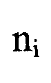
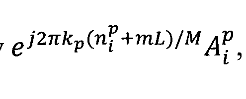
  • n j +mL being respectively with k integer such as 0 with m integer such as and j the imaginary
  • Such transmission of the Q symbols enables to obtain that the samples of these symbols in the frequency domain are arranged in a comb structure while preserving the single carrier property of the DFTsOFDM scheme. Moreover, the single carrier property is preserved even if other symbols (in positions different from ni+mL with ( are multiplexed in the same DFTsOFDM symbol according to the invention.
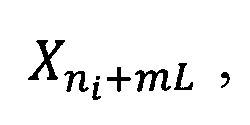
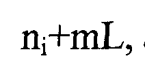
  • the single carrier property of the DFTsOFDM scheme is preserved, since the radio signal transmitting the samples of the Q symbols is the same as a radio signal obtained by applying a DFT and an IDFT on a block of M symbols with values of symbols in the positions n+mL, being
  • the IDFT size is generally larger than the
  • the radio signal transmitting the Q symbols according to the invention is the same as the radio signal obtained by processing, through a DFTsOFDM scheme, the symbols arranged according to the invention in the block of M symbols. Therefore, the single carrier property of the DFTsOFDM scheme is preserved.
  • the samples of the Q symbols in the frequency domain are arranged in a comb structure, that is, the Q symbols only occupy specific frequencies in the frequency domain, which are the frequencies with index
  • each symbol Aj of the group of symbols enhances the quality of the transmission of these Q symbols.
  • the symbol Ai is repeated K times with a phase shift of between each repetition. Therefore, using K symbols in the block of symbols to transmit each symbol Aj enhances the transmission quality of these symbols. Thus, less transmission error occurs regarding the Q symbols.
  • This phase shift repetition of symbols can be advantageously used to transmit reference signals. Indeed, if the value of a symbol Aj is known from the receiver and that the receiver knows the position and the phase shift applied, then the receiver has relevant information to deduce the canal quality when receiving the symbol Aj and its phase shifted copies. Thus, the symbol Ai and all its phase shifted copies can be used as reference signals. Therefore, especially when tracking fast phase shift, the symbol Ai and all its phase shifted copies are relevant as reference signals since they are temporally distributed in the DFTsOFDM symbol while being multiplexed with other symbols.
  • K and Q are directly linked to the effective coding rate of, e.g., the information bits represented by the group of Q symbols, convenient choice of K and Q may be used in the case of transmitting control data with increased quality of transmission.
  • a group of symbol transmitting control data may need a transmission with low error occurrence whereas the consequences of error occurring on the transmission of symbols from a group of symbols that transmit user data may be less crucial for the communication.
  • K and Q are directly linked to the ratio between the power of the group of Q symbols and the power of the remaining symbols
  • K and Q may be used in the case of transmitting a reference signal represented by the group of Q symbols for meeting target requirements in terms of, e.g., channel estimation quality.
  • the group of Q symbols can be conveniently used for example as DMRS, with an overhead of 50% and a comb 1/2 frequency structure
  • the group of Q symbols can be conveniently used for example as DMRS, with an overhead of 25% and a comb 1/2 frequency structure.
  • the group of Q symbols can be conveniently used for example as DMRS, with an overhead of 50% and a comb 1/4 frequency structure.
  • Q and possibly K can be chosen such that a target effective coding rate is achieved for the transmission of a the group of Q symbols: for conveying a given number of information bits, increasing Q allows a higher number of redundancy bits, and increasing K increases the number of repetitions.
  • IDFT inverse Discrete Fourier transform
  • the samples of each symbol X n contribute to the radio signal and/or to the frequency domain signal out-putted by the DFT.
  • the samples of different symbols X n can be seen, from a mathematical point of view, as a multi-dimensional structure having as dimensions the size N of the IDFTs and the number of transmit antennas.
  • p n such as the samples in the radio signal can be obtained by applying the DFTsOFDM scheme to the block X* n) , with the value of X n set to p n .
  • the samples in the radio signal of the symbol Aj are defined relatively to the symbols in the positions li +mL, that is the samples of the symbol Aj is the sum of the samples of the symbols with .
  • the value p n is
  • the symbols in the positions nj+mL in the block of symbols are respectively set to the value and the
  • DFTsOFDM scheme is applied to the block of symbols (referred to as pre- DFT incorporation).
  • the block of symbols are respectively set to 0 in the block of symbols, and the samples in the frequency domain of the symbols Ai are added at the output of the DFT, or at the input of the IDFT (referred to as post-DFT incorporation).
  • post-IDFT incorporation the samples in the radio signal of the symbols A are added at the output of the IDFT (referred to as post-IDFT incorporation).
  • the samples in the radio signal and the radio signal itself are fully defined as the result of the application of the DFTsOFDM scheme on a block of M symbols whose symbols are set to specific values.
  • the specific value of the samples of the symbol X is the corresponding value of the samples of the symbol X.
  • the specific values of the sample Ai are the corresponding values of the samples of the symbols with
  • the M - Q.K symbols other than the Q symbols defined according to the invention can be used freely, that is, with or without implementing them so that their samples in the frequency domain are arranged in a comb structure, and having these symbols result from any types of symbols such as control data, reference signal or user data.
  • the Q symbols A j may be reference signals (issued from a CAZAC sequence or a advantageously Zadoff-Chu sequence) and the M - Q.K other symbols may contain user data and/or other control data and/or other type of reference signals.
  • the Q symbols A may be user data and the M - Q.K other symbols may contain reference signals and/or also user data and/or control data etc.
  • the symbol Ai is for
  • a modulation symbol like a QPSK modulation symbol or a symbol from a given sequence such as a CAZAC sequence or a symbol from a predefined sequence with controlled PAPR for example.
  • phase shifted symbols of a digital modulation scheme can be for examples phase shifted symbols of a digital modulation scheme, or phase shifted symbols taken from a CAZAC sequence or from another predefined sequence with controlled PAPR.
  • Samples of the symbol Ai are the same than the samples of the symbols X ni+m L, with 0 ⁇ m ⁇ K.
  • the index k and the integer K define the comb. Indeed, the comb defined by (k; K) (hereafter named comb k) occupies the subcarriers with the frequencies index k, k+K, k+2K,..., k+(L-l)K. Therefore, the Q symbols Ai occupy only the subcarriers corresponding to the comb k.
  • the transmit antenna is configured for transmitting on M frequencies, that is that the signal emitted by such transmitting antenna is provided by applying an N-size IDFT on M complex symbols, one complex symbol for each of the M allocated subcarriers.
  • the M subcarriers may be mapped with a subcarrier mapping module on a greater number of N subcarriers. N-M of these subcarriers are not allocated subcarriers since they are set to zero, the M other subcarriers are M allocated subcarriers, on which the M complex symbols are mapped.
  • the IDFT module is of size
  • the radio signal is understood as the signal provided by the transmit antenna.
  • the scheme applied on the block of symbols is a DFTsOFDM scheme, that is, successively applying a DFT module, a subcarrier mapping module and an IDFT module.
  • transmitting the Q symbols is done by setting the symbol t0 the value for each i
  • the Q symbols are incorporated at a pre-DFT level, in the block of symbols.
  • Such an implementation can easily be adapted in any standard emitter and therefore can be implemented in all transmitters. Moreover, there is no need for additional operations such as post-IDFT processing or memory storage of the samples of the Q symbols.
  • the method further comprises setting the values of the symbols with
  • transmitting the Q symbols is done by adding the samples in said subsequent signal at the output of the IDFT module.
  • the Q symbols can be processed in a different manner from the other symbols of the block of symbols.
  • This enables for example to process the samples of the Q symbols once and for all.
  • This enables for example to control the interferences of the samples of the Q symbols with the samples of the other symbols by specific processing applied onto the samples of the Q symbols and/or onto the samples of the other symbols.
  • the samples of the Q symbols are computed separately from the other symbols to obtain samples identical or at least equivalent (that is identical in regard to the high power samples) to those that would have been obtained by setting the Q symbols pre-DFT, that is by setting the values of the symbols to the corresponding values of the samples
  • the samples of the Q symbols may be samples computed
  • the subsequent signal is the signal provided by the DFTsOFDM-like scheme at the output of the IDFT, which in this case is obtained by applying the scheme to a block of symbols where the values of the symbol are set to 0, at least for some pairs of
  • the method further comprises setting the values of the symbols to 0, with
  • transmitting the Q symbols is done by adding the samples in said subsequent signal at the output of the DFT module.
  • the samples of the Q symbols are computed separately regarding the DFT from the other symbols to obtain samples identical or at least equivalent (that is identical in regard to the high power samples) to those that would have been obtained by setting the Q symbols pre-DFT, that is by setting the values of the symbols with , to the
  • the subsequent signal is the signal provided by the DFTsOFDM-like scheme at the output of the DFT, which in this case is obtained by applying the DFT to a block of symbols where the values of the symbols X are set to 0, at least for some pairs of
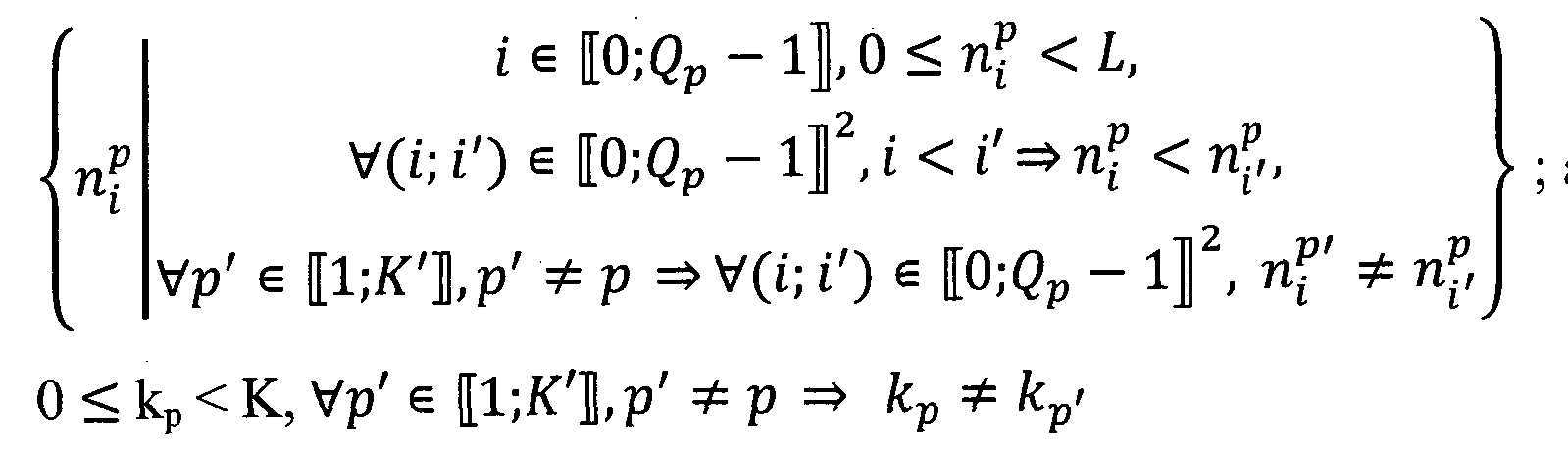
  • At least K’ groups of symbols are transmitted in the radio signal, with the being strictly positive integers and said method comprising
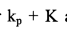
  • each comb being defined by its index k p and by K. Indeed, the comb defined by (hereafter named comb k p ) occupies the
  • each comb occupies different frequencies in the frequency domain and does not overlap with the other combs.
  • each group of Q p symbols are processed such as to be orthogonal in the frequency domain to the other groups, which enables at the receiver side to easily retrieve from the radio signal each group of Q symbols . Indeed, being orthogonal in the
  • frequency domain enables to separate the groups of Q p symbols from each other at the receiver side, simplifying the frequency domain processing at the receiver.
  • Each group of symbols can be used for a specific type of symbol for example reference signals or other control data or user data. Therefore, all the symbols of each group can be of a specific type enabling to easily separate the different types of symbols at the receiver side enabling to process them independently from each other. Therefore, types of symbols or more generally groups of symbols needing different types of processing at the receiver side can be multiplexed within one DFTsOFDM symbol.
  • such processing at the receiver enables to extract the reference signals to evaluate the channel perturbation (phase shift, amplitude%) which has altered the radio signal and to adapt the decoding modules to compensate these perturbations, which enables to enhance the efficiency of the decoding of the radio signal.
  • each group of symbols Q p can be chosen regarding the quality of the transmission required for the symbols of that group. For example, a group of symbol transmitting control data may need a transmission with low error occurrence whereas the consequences of error occurring on the transmission of symbols from a group of symbols that transmit data may be less critical for the communication.
  • each group of symbols are frequency domain orthogonal and no interference from other symbols of the block of symbols can occur since they are set to zero.
  • the symbols in the block of symbols which carry the Q p symbols are arranged in a comb in the time domain.
  • the samples of the Q p symbols in the frequency domain are in comb k p .
  • the samples in the frequency domain of the Q symbols which occupy the subcarrier k p are identical to the ones occupying the subcarriers
  • the samples of the Q p symbols have a repetitive structure.
  • This repetitive structure reduces the complexity of the computing to retriever the symbols. Indeed, the receiver will receive several times the same complex symbols on different subcarriers which reduces the consequences of the deterioration of these complex symbols during their transmission through the radio channel and of the interferences.
  • this repetitive structure reduces the complexity of the computing to process the Q p symbols especially when the symbols are not incorporated in a pre-DFT manner. Indeed, in that case only the samples in the frequency domain on the first Q p subcarriers of the k p comb need to be computed, that is the samples on the subcarriers of the comb k p indexed by k p ,
  • phase shift repetition of symbols in the time domain can be advantageously used to transmit reference signals.
  • the symbols in the block of symbols which carry the Q p symbols are arranged in a comb in the time domain since then not only the symbol A; and all its phase shifted copies are temporally distributed but all the symbols Aj and their phase shifted copies are temporally distributed in the DFTsOFDM symbol. That is, the symbols which carry the Q p symbols are arranged in a comb with a step of c in the time domain. Therefore, this structure is particularly relevant for incorporating reference signals.
  • the symbols in the block of symbols which carry the Q p symbols are arranged in a localized manner in the time domain, that is, for each m from 0 to K-l the symbols
  • the receiver can extract these contiguous samples in the radio signal (for example using time window) in a less complex manner (at the most K time windows are required) than if they were distributed in the DFTsOFDM symbol (may require K.L time windows).
  • the other symbols in the block of symbols interferes less in the time domain onto the Q symbols. Indeed, the symbols are
  • die samples of the Q symbols in the frequency domain are an oversampling of the result of a -size DFT applied on the symbols.
  • a Zadoff-Chu sequence is also a CAZAC sequence, respectively a Zadoff-Chu sequence.
  • the oversampling of this result is the samples in the frequency domain of these Q symbols (generated from a CAZAC sequence or a Zadoff-Chu sequence).
  • This oversampling has low envelope variations, that is, a low PAPR, and has some orthogonal multiplexing capacity.
  • such oversampling enables to add samples of the Q p symbols directly in the frequency domain with low computing complexity.
  • a second aspect of the invention concerns a computer program product comprising code instructions to perform the method as described previously when said instructions are run by a processor.
  • a third aspect of the invention concerns a device for transmitting at least a group of Q symbols (Ao; A Q _ I ) in a radio signal to be transmitted over a wireless communication system, said radio signal being intended to be emitted by an emitter comprising at least one transmit antenna configured for transmitting on at least a number M, of different frequencies, M being equal to L.K with L and K strictly positive integer and Q being a strictly positive integer strictly smaller than L, said radio signal being provided by:
  • said device being configured to:
  • Figure 1 illustrates a DFTsOFDM type transmitter and receiver.
  • Figure 2 schematizes a block diagram of a classical DFTsOFDM transmitter.
  • FIG. 3 details an example of localization of the Q symbols in the block of symbols according to the invention.
  • Figure 4 schematizes a block diagram of pre-DFT incorporation of Q symbols according to the invention.
  • Figure 5 schematizes a block diagram of post-DFT incorporation of Q symbols according to the invention.
  • Figure 6 schematizes a block diagram of post-IDFT incorporation of Q symbols according to the invention.
  • Figure 7.1 illustrates a flowchart representing the steps of pre-DFT incorporating the symbols according to the invention.
  • FIG. 7.2 illustrates a flowchart representing the steps of post-DFT incorporating the symbols according to the invention.
  • Figure 7.3 illustrates a flowchart representing the steps of post-IDFT incorporating the symbols according to the invention.
  • a transmitter 1.1 transmitting a radio signal to a receiver 1.2.
  • the receiver 1.2 is in the cell of the transmitter 1.1.
  • This transmission is a DFTsOFDM based transmission in the context of OFDM based system.
  • the transmitter 1.1 is a fixed station and the receiver 1.2 is a mobile terminal, in the context of LTE they would be named a base station and a user equipment.
  • the transmitter 1.1 can as well be the mobile terminal and the receiver 1.2 a fixed station.
  • the transmitter 1.1 comprises one communication module (COM trans) 1.3, one processing module (PROC trans) 1.4 and a memory unit (MEMO trans) 1.5.
  • the MEMO trans 1.5 comprises a non-volatile unit which retrieves the computer program and a volatile unit which retrieves symbol incorporation parameters.
  • the PROC trans 1.4 is configured to transmit the Q symbols according to the invention.
  • the COM trans 1.3 is configured to transmit to the receiver 1.2 the radio signal.
  • the communication module 1.3, the processing module 1.4 and the memory unit 1.5 may constitute the device for transmitting the Q symbols, as previously described.
  • the receiver 1.2 comprises one communication module (COM recei) 1.6, one processing module (PROC recei) 1.7 and a memory unit (MEMO recei) 1.8.
  • the MEMO_recei 1.8 comprises a non-volatile unit which retrieves the computer program.
  • the PROC recei 1.7 is configured to retrieve the Q symbols from the radio signal.
  • the COM recei 1.6 is configured to receive from the transmitter 1.1 the radio signal.
  • FIG 2 there is shown a block diagram of a classical DFTsOFDM transmitter 1.1.
  • Such DFTsOFDM transmitter applies a DFTsOFDM scheme on a block of symbols to obtain the radio signal.
  • DFTsOFDM scheme has a single carrier property which ensures low Peak-to-Average Power Ratio (PAPR), depending on the PAPR of the block of symbols present at the input of the DFT.
  • PAPR Peak-to-Average Power Ratio
  • the DFTsOFDM transmitter emits a radio signal by emitting on one transmit antenna Tx 2.0, this is none limiting and the DFTsOFDM transmitter can as well transmit by using several transmit antennas.
  • the symbols of the block of symbols may be obtained by a QPSK digital modulation scheme or any other digital modulation scheme as QAM, or may be symbols of a sequence with controlled PAPR (e.g. a CAZAC sequence).
  • M complex symbols are obtained in the frequency domain, which are That is, one complex symbol is obtained for each /- th subcarrier among the M allocated subcarriers.
  • These complex symbols are mapped, with a subcarrier mapping module 2.2 in the frequency domain to M out of N inputs of a N-size IDFT module 2.3.
  • the vector of complex symbols S is mapped to the M allocated subcarriers out of N existing subcarriers via subcarrier mapping module 2.2.
  • the subcarrier mapping can be for example localized, that is, the M elements of the vector S are mapped to M consecutive subcarriers among the N existing.
  • the subcarrier mapping can be for example distributed, that is the M elements of the vector S are mapped equally distanced over the entire bandwidth with zeros occupying unused subcarriers.
  • N-size inverse DFT module 2.3 is then applied to the resulting vector S of the subcarrier mapping module 2.2, therefore generating a DFTsOFDM symbol which is transmitted via the transmit antenna 2.0. More precisely, at the output of the IDFT module 2.3 a signal is obtained.
  • This signal occupies during a time interval corresponding to a DFTsOFDM symbol, M allocated subcarriers out of the N existing subcarriers.
  • the signal x is a time-domain signal whose frequency-domain representation, during the time interval, are the complex symbols S z for each occupied subcarrier with This time-domains signal corresponds to a DFTsOFDM symbol. Therefore, samples in the signal x refer to samples in a DFTsOFDM
  • a cyclic prefix can be optionally appended after IDFT.
  • FIG 3 there is shown an example of localization of the Q symbols in the block of symbols according to the invention.
  • the k-th comb or comb k is a subcarrier comb made of the subcarriers of index k +m.K with m from 0 to K-l .
  • the S are considered as resulting only from the Q symbols, that is, S with A’(q) defined by the A with .
  • symbols in different positions than the nj+m.L are set to non-nul values, then samples in the frequency domain of these symbols may occupy subcarriers of the k-th comb. These samples can be considered as interference regarding the Q symbols.
  • the DFT is applied on the block of symbols in which the Q symbols are previously incorporated. It is referred to such embodiment as pre-DFT incorporation of the Q symbols.
  • Figure 4 is a block diagram of a DFTsOFDM transmitter where the incorporation of Q symbols according to the invention is a pre-DFT incorporation.
  • a modulator module 4.0 is configured to insert modulation symbols into the block of symbols in positions that do not conflict with the positions with
  • module 4.1 is configured to add the symbols set to in the
  • the incorporator module 4.1 may be configured to inform or configure the modulator module 4.0 to avoid the insertion of modulation symbols into the block of symbols in positions that do not conflict with the positions n* + mL with
  • the incorporator module 4.1 determines the Q positions in the block of symbols
  • the incorporator module 4.1 may be configured in a static way by previously configuring the positions with Several configurations may also be previously programmed, for example one configuration for each number Q, or a limited number of configurations for each number Q. Configuration can be done in an implicit manner (for example based on other parameters known by the transmitter), or in an explicit manner (for example based on instructions given by the base station via, e.g., a control channel), or a combination of the two.
  • the incorporator module 4.1 determines, for each p from 1 to K’, a k p integer and Q p positions nf in the block of symbols such as
  • the incorporator module 4.1 is then configured to add the symbols set to in the positions nf + mL in the block of
  • the modulator module 4.0 is configured accordingly. Each of the Q p group of symbols is therefore incorporated in the same manner as if only one group of symbols is incorporated according to the invention. [0096]
  • the complex symbols issued from each -group of Q p symbols on which the DFT has been applied are on subcarriers of different combs. Therefore, samples in the frequency domain of symbols of the Q p group are on the k p -th comb, while samples in the frequency domain of symbols of the Q p ⁇ group are on the k p -th comb. Thus, the samples in the frequency domain of symbols of different groups do not superpose, they are frequency domain orthogonal.
  • the modulator module 4.0 is then configured to set the symbols to zero in the positions where no symbols are incorporated by the incorporator module 4.1. Therefore, in this case the block of symbols at the output of the modulator module 4.0 is only composed of zeros.
  • the number K’ of combs can be set to be strictly smaller than K. That is, the combs ki,..., k K ⁇ do not occupy all the subcarriers in the frequency domain, at least a group of subcarriers forming another comb is left unused. Therefore, when several transmitters like the transmitter 1.1 are nearby and could induce interferences on the signal of each other, one transmitter can emit symbols according to the invention using the combs ki,..., k K ⁇ and the other transmitters can use different combs, that is combs containing the subcarriers with the index k+mK, with m from 0 to L-l and k different from .
  • the radio signals emitted by the transmitters are orthogonal in the frequency domain, and thus they do not induce interferences to each other and are easy to separate in the frequency domain at the receiver.
  • This is specifically relevant when the transmitters are mobile terminals in the same cell of a base station, therefore, the incorporation is implemented in an uplink transmission. This is also relevant when the transmitters are base stations that are close to each other, for example in an urban context.
  • the symbols from a group of symbols can be arranged in a comb in the block of symbols, that is, in the time domain. That is, for each pair
  • the symbols of the group of Q p symbols are spaced from c-1 positions in the block of symbols. That is, the Q p positions rtf in the block of symbols are determined such as
  • 4.1 is configured to add the symbols set to
  • subcarrier k p are identical to the ones occupying the subcarriers
  • the symbols from a group of Q p symbols can be arranged contiguously in the block of symbols (in the time domain). That is, for each pair
  • module 4.1 is configured to add the symbols X set to
  • the Q (or Q p symbols) symbols may be symbols of any types of symbols such as control data, reference signals or user data.
  • the Q symbols are reference signal symbols, advantageously the Q symbols may be chosen as a CAZAC sequence, advantageously the Q symbols may be chosen as a Zadoff-Chu sequence.
  • FIG 5 there is shown a block diagram of post-DFT incorporation of the Q symbols according to the invention. This embodiment can be applied as described hereafter to each of the K’ groups of Q p symbols.
  • the incorporation of the Q symbols is not done in the block of symbols (that is by setting directly the values of the symbols of the block of symbols as shown in figure 4).
  • the incorporation is done post- DFT.
  • the modulator module 5.0 is configured to set the values of the symbols to 0 before applying the DFT module 2.1.
  • the modulator module 5.0 may be configured by the incorporator module 5.1, which can send the position configuration.
  • the other symbols of the block of symbols may be set freely by the modulator module
  • the incorporator module 5.1 adds to the subsequent signal at the
  • the signal is for
  • the samples of the Q symbols are computed to obtain samples identical or at least equivalent to those that would have been obtained, at the output of the DFT, for example if the values of these symbols where set pre-DFT (directly in the block of symbols) as previously described.
  • S Incor can be obtained by applying a DFT to a block of symbols where the values of the symbols i with ( are set respectively to the values
  • ncor and 5 are mapped, as described in figure 2, with the subcarrier mapping module 2.2 in the frequency domain to M out of N inputs of a N-size IDFT module 2.3. Then, the N-size inverse DFT module 2.3 is applied to the resulting vector S of the subcarrier mapping module 2.2, therefore generating a DFTsOFDM symbol which is transmitted via the transmit antenna 2.0.
  • the signal obtained at the output of the adder, 5 are identical (or at least equivalent) to the signal at the output of the DFT module 2.1 when the Q symbols are incorporated pre-DFT.
  • the signal obtained at the output of the adder, 5, is completely defined, except for the non-incorporated symbols, by the symbols in the block of symbols whose values are set to zero, and by the corresponding value of the samples of the symbols
  • the incorporator module 5.1 may be configured in a static way by previously configuring the positions 3 ⁇ 4 with
  • Configuration can be done in an implicit manner (for example based on other parameters known by the transmitter), or in an explicit manner (for example based on instructions given by the base stationvia, e.g., a control channel), or a combination of the two.
  • FIG 6 there is shown a block diagram of post-IDFT incorporation of the Q symbols according to the invention. This embodiment can be applied as described hereafter to each of the K’ groups of Q p symbols.
  • the incorporation of the Q symbols is not done in the block of symbols (that is by setting directly the values of the symbols of the block of symbols as shown in figure 4) nor in the frequency domain (as shown in figure 6).
  • the incorporation is done post-IDFT.
  • the modulator module 6.0 is configured to set the values of the symbols with to 0 before applying
  • the modulator module 6.0 may be configured by the incorporator module 6.1, which can send the position configuration.
  • the other symbols of the block of symbols may be set freely by the modulator module
  • the N-size inverse DFT module 2.3 is then applied to the resulting vector of the subcarrier mapping module 2.2. At the output of the IDFT
  • the signal is a time-domain signal whose frequency-domain representation are the
  • the incorporator module 5.1 adds to the subsequent signal at the output of the IDFT module 2.3 the signal
  • the signal x is pre- computed samples of the symbols with x That is, rather than setting the values of the symbols X with
  • the samples of the Q symbols are computed to obtain samples identical or at least equivalent to those that would have been obtain, at the output of the IDFT module 2.3 if the values of these symbols where set pre-DFT (directly in the block of symbols) as previously described.
  • S t can be obtained by applying a DFTsOFDM scheme (DFT module 2.1, Subcarrier mapping module 2.2 and
  • IDFT module 2.3 to a block of symbols where the values of the symbols are set respectively to the
  • a cyclic prefix can be optionally appended after IDFT.
  • the signal x t0 ensure that the samples in the signal of the symbols whose values have been set to
  • the signal obtained at the output of the adder, x are identical (or at least equivalent) to the signal at the output of the IDFT module 2.3 when the Q symbols are incorporated pre-DFT.
  • the signal obtained at the output of the adder, x is completely defined, except for the non-incorporated symbols, by the symbols in the block of symbols whose values are set to zero, and by the corresponding value of the samples of the symbols
  • the incorporator module 6.1 may be configured in a static way by previously configuring the positions with Several configurations may also be previously programmed,
  • Configuration can be done in an implicit manner (for example based on other parameters known by the transmitter), or in an explicit manner (for example based on instructions given by the base stationvia, e.g., a control channel), or a combination of the two.
  • FIG 7.1 there is shown a flowchart representing the steps of pre-DFT incorporating the symbols according to the invention.
  • the incorporation module 4.1 is configured either in a static way or dynamically (that is that the incorporation module 4.1 is reconfigured depending for example on instructions given by the base station through a control channel), or by a combination of the two.
  • the incorporation module 4.1 may choose another configuration upon those saved in the MEMO trans 1.5. Indeed, several configurations may be pre-parametered in the incorporation module 4.1, those configurations can be ordered according to the number Q of symbols incorporated by the configuration.
  • a configuration may be defined by the number Q, M and/or L, by the positions in the block of symbols X of the symbols which
  • the incorporation module 4.1 may inform the modulator module 4.0 of the chosen configuration. Enabling the modulator module 4.0 to insert modulation symbols into the block of symbols in positions that do not conflict with the positions
  • the incorporation module 4.1 incorporates the Q symbols as previously described, by setting each value of the symbols X tract which are at positions L with (i; m) to respectively the
  • step S 13 the signal is processed, by applying a DFTsOFDM scheme to the block of symbols as previously described.
  • step S14 the signal is emitted by Tx 2.0.
  • FIG 7.2 there is shown a flowchart representing the steps of post-DFT incorporating the symbols according to the invention.
  • the incorporation module 5.1 is configured as in figure 7.1 either in a static way or dynamically or by a combination of the two.
  • the incorporation module 5.1 may inform the modulator module 5.0 of the chosen configuration.
  • the modulator module 5.0 sets the values of the symbols with
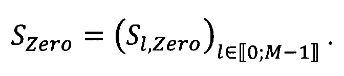
  • step S23 the DFT module 2.1 is applied on the incomplete block of symbols X as previously explained in figure 5.
  • step S24 the incorporation module 5.1 adds to the signal S Zero the near as described in figure 5.
  • the remaining DFTsOFDM scheme (subcarrier mapping module 2.2, IDFT module 2.3) is applied on the signal 5 resulting from the sum of
  • step S26 the signal is emitted by Tx 2.0.
  • the incorporation module 6.1 is configured as in figure 7.1 either in a static way or dynamically or by a combination of the two.
  • the incorporation module 6.1 may inform the modulator module 6.0 of the chosen configuration.
  • step S32 based on the configuration the modulator module 6.0 sets the values of the symbols
  • step S33 the signal is processed, that is on the block of symbols is applied the DFTsOFDM scheme (DFT module 2.1, subcarrier mapping module 2.2, IDFT module 2.3).
  • DFT module 2.1 subcarrier mapping module 2.2
  • IDFT module 2.3 IDFT module 2.3
  • the incorporation module 6.1 adds to the output signals of the IDFT module 2.3, the signal
  • the signal may be
  • step S35 the signal is emitted by Tx 2.0.

Landscapes

  • Engineering & Computer Science (AREA)
  • Computer Networks & Wireless Communication (AREA)
  • Signal Processing (AREA)
  • Physics & Mathematics (AREA)
  • Discrete Mathematics (AREA)
  • General Physics & Mathematics (AREA)
  • Mathematical Physics (AREA)
  • Radio Transmission System (AREA)
  • Mobile Radio Communication Systems (AREA)

Abstract

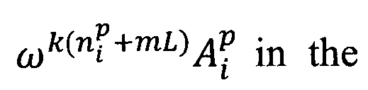
The invention relates to a method for transmitting a group of Q symbols (A0;...; AQ-1) in a DFTsOFDM radio signal, said radio signal being provided by applying a M size DFT and a N-size IDFT to a block of symbols X=(X0,...ΧΜ-1), said method comprising: - determining Q positions ni in the block of symbols, such as (I); - transmitting the Q symbols through the radio signal, such as for each i, samples of the symbol ai in the radio signal are equal to a result of the application of a DFTsOFDM scheme to a block of M symbols with values of symbols Xni+mL, being e j2πk(ni+mL)/M A i with k integer such as 0 ≤ k < K, with m integer such as 0 ≤ m < K.

Description

[DESCRIFTION]
[Title of Invention]
SYMBOLS INCORPORATION SCHEME FOR DFT-S-OFDM
[Technical Field]
[0001]
The present invention generally relates to the domain of telecommunication system, and more specifically to the incorporation of symbols like reference signals in the context of communications using OFDM transmission schemes.
[Background Art]
[0002]
It may be necessary to incorporate the symbols in such a manner as they occupy specific combs in the frequency domain. For example, the standards may require reference signals (such as demodulation reference signals - DMRS) to be set on specific subcarriers in the frequency domain.
[0003]
For this purpose, the symbols (for example the DMRS) are incorporated directly in the frequency domain on the desired subcarriers of the desired comb, the other symbols in the frequency domain are then processed using subcarriers unused by the comb. Therefore, the symbols using the frequency domain comb are incorporated independently from the other symbols, thus, the single carrier property of schemes like the DFTsOFDM scheme is not preserved, leading to high peak to average power ratio (PAPR). To avoid having a high PAPR, in the new standard NR (new radio) only the DMRS are incorporated, leaving the other symbols set to zero, leading to an important loss of spectral efficiency.
[0004] Therefore, multiplexing groups of symbols occupying combs in the frequency domain with other symbols may lead to high PAPR and important interferences.
[Summary of Invention]
[0005]
The present invention aims at improving the situation.
[0006]
To that end, the invention relates to a method for transmitting at least a group of Q symbols (Ao; ...; AQ_I) in a radio signal to be transmitted over a wireless communication system, said radio signal being intended to be emitted by an emitter comprising at least one transmit antenna configured for transmitting on at least a number M, of different frequencies, M being equal to L.K with L and K strictly positive integer and Q being a strictly positive integer strictly smaller than L, said radio signal being provided by :
- applying a M size DPT to a block of symbols X , and
Figure imgf000004_0001
obtaining for each k& frequency, with k = 0 to M-l, a complex symbol Sk in the frequency domain;
- obtaining, at an output of an IDFT module corresponding to a transmit antenna a signal representing, in the frequency domain, complex symbols respectively function of Sk for each k* frequency with k = 0 to
Figure imgf000004_0002
- emitting the radio signal corresponding to the signal;
said method comprising:
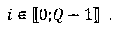
- determining Q positions n5 in the block of symbols, such as
Figure imgf000004_0003
- transmitting the Q symbols through the radio signal, such as for each i, samples of the symbol Ai in the radio signal are equal to a result outputted by the IDFT module, of the application of the DFT to a block of M symbols with values of symbols in the positions
Figure imgf000005_0004
nj+mL, being respectively
Figure imgf000005_0006
with k integer such as 0 with m integer such as and j the imaginary
Figure imgf000005_0005
Figure imgf000005_0007
number.
[0007]
Such transmission of the Q symbols enables to obtain that the samples of these symbols in the frequency domain are arranged in a comb structure while preserving the single carrier property of the DFTsOFDM scheme. Moreover, the single carrier property is preserved even if other symbols (in positions different from ni+mL with (
Figure imgf000005_0001
are multiplexed in the same DFTsOFDM symbol according to the invention.
[0008]
The single carrier property of the DFTsOFDM scheme is preserved, since the radio signal transmitting the samples of the Q symbols is the same as a radio signal obtained by applying a DFT and an IDFT on a block of M symbols with values of symbols in the positions n+mL, being
Figure imgf000005_0002
respectively The IDFT size is generally larger than the
Figure imgf000005_0003
DFT size. That is, the radio signal transmitting the Q symbols according to the invention is the same as the radio signal obtained by processing, through a DFTsOFDM scheme, the symbols arranged according to the invention in the block of M symbols. Therefore, the single carrier property of the DFTsOFDM scheme is preserved.
[0009]
According to the invention the samples of the Q symbols in the frequency domain are arranged in a comb structure, that is, the Q symbols only occupy specific frequencies in the frequency domain, which are the frequencies with index
Figure imgf000006_0002
[0010]
In addition, the phase shifted repetition of each symbol Aj of the group of symbols enhances the quality of the transmission of these Q symbols. Indeed, the symbol Ai is repeated K times with a phase shift of
Figure imgf000006_0001
between each repetition. Therefore, using K symbols in the block of symbols to transmit each symbol Aj enhances the transmission quality of these symbols. Thus, less transmission error occurs regarding the Q symbols.
[0011]
This phase shift repetition of symbols can be advantageously used to transmit reference signals. Indeed, if the value of a symbol Aj is known from the receiver and that the receiver knows the position and the phase shift applied, then the receiver has relevant information to deduce the canal quality when receiving the symbol Aj and its phase shifted copies. Thus, the symbol Ai and all its phase shifted copies can be used as reference signals. Therefore, especially when tracking fast phase shift, the symbol Ai and all its phase shifted copies are relevant as reference signals since they are temporally distributed in the DFTsOFDM symbol while being multiplexed with other symbols.
[0012]
Moreover, it is possible to control the quality of the transmission of the Q symbols by conveniently choosing K and Q. Indeed, the size Q of the group of symbols and the number of phase shifted repetitions K can be chosen regarding the quality of the transmission required for the symbols of that group. For example, since K and Q are directly linked to the effective coding rate of, e.g., the information bits represented by the group of Q symbols, convenient choice of K and Q may be used in the case of transmitting control data with increased quality of transmission. A group of symbol transmitting control data may need a transmission with low error occurrence whereas the consequences of error occurring on the transmission of symbols from a group of symbols that transmit user data may be less crucial for the communication. For example, for a given fixed transmit power per DFTsOFDM symbol, since K and Q are directly linked to the ratio between the power of the group of Q symbols and the power of the remaining symbols, convenient choice of K and Q may be used in the case of transmitting a reference signal represented by the group of Q symbols for meeting target requirements in terms of, e.g., channel estimation quality. For example, choosing Q=M/4 and K=2 leads to using half of the transmit power for conveying the group of Q symbols, which will be present onto half of the subcarriers in the frequency domain (occupying the comb occupying half of the frequency structure: referred as comb 1/2 frequency structure) (every other subcarrier contains information relative to the group of Q symbols). Thus, the group of Q symbols can be conveniently used for example as DMRS, with an overhead of 50% and a comb 1/2 frequency structure For example, choosing Q=M/8 and K=2 leads to using a quarter of the transmit power for conveying the group of Q symbols, which will be present onto half of the subcarriers in the frequency domain (every other subcarrier contains information relative to the group of Q symbols). Thus, the group of Q symbols can be conveniently used for example as DMRS, with an overhead of 25% and a comb 1/2 frequency structure. For example, choosing Q=M/8 and K=4 leads to using a half of the transmit power for conveying the group of Q symbols, which will be present onto a quarter of the subcarriers in the frequency domain (every 4th subcarrier contains information relative to the group of Q symbols, therefore, occupying the comb occupying a quarter of the frequency structure: referred as comb 1/4 frequency structure). Thus, the group of Q symbols can be conveniently used for example as DMRS, with an overhead of 50% and a comb 1/4 frequency structure. In yet another example, Q and possibly K can be chosen such that a target effective coding rate is achieved for the transmission of a the group of Q symbols: for conveying a given number of information bits, increasing Q allows a higher number of redundancy bits, and increasing K increases the number of repetitions.
[0013]
Note that for a given M conveniently choosing K is equivalent to conveniently choosing L, since KL=M. A convenient choice of (K, L) fixes the frequency structure of the comb used by the sequence represented by the group of Q symbols. Furthermore, a convenient choice of Q fixes the amount of power utilized for conveying the sequence represented by the group of Q symbols (which can be interpreted either as the power boosting level onto the L subcarriers in the used comb, or the overhead of the sequence, or an indicator of the effective coding rate used by the sequence).
[0014]
By DFT it is understood Discrete Fourier transform.
[0015]
By IDFT it is understood inverse Discrete Fourier transform.
[0016]
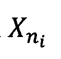
By samples of a symbol X„ in the frequency domain and by samples of a symbol Xn in the radio signal it is understood the result in the frequency domain of applying the DFT, respectively the result at the output of the IDFT of the processing of the DFTsOFDM scheme, on the block of symbols whose symbols are set to zero except for the symbol Xn (such block of symbols being referred to as X(n)). By analogy, by samples of a symbol Ai in the frequency domain and by samples of a symbol A; in the radio signal it is understood result in the frequency domain of applying the DFT, respectively the result at the output of the IDFT of the processing of the DFTsOFDM scheme, on the block of symbols whose symbols are set to zero except for the symbols containing the symbol that is except for the symbols with
Figure imgf000009_0007
Figure imgf000009_0006
Figure imgf000009_0005
[0017]
These definitions are relevant since the DFT and the DFTsOFDM scheme are linear schemes.
[0018]
Moreover, the samples of each symbol Xn (or symbol AJ, which may overlap, contribute to the radio signal and/or to the frequency domain signal out-putted by the DFT. The radio signal issued from applying the scheme on block symbols X=(Xo, ···, XM-I) is equal to the sum of the samples of the symbols Xn, n integer from 0 to M-l. Here, the samples of different symbols Xn can be seen, from a mathematical point of view, as a multi-dimensional structure having as dimensions the size N of the IDFTs and the number of transmit antennas.
[0019]
Therefore, by samples in the radio signal of the symbol Xn of the block of symbols it is understood that there exists a value pn such as the samples in the radio signal can be obtained by applying the DFTsOFDM scheme to the block X*n), with the value of Xn set to pn. The samples in the radio signal of the symbol Aj are defined relatively to the symbols in
Figure imgf000009_0004
the positions li +mL, that is the samples of the symbol Aj is the sum of the samples of the symbols with . The value pn is
Figure imgf000009_0003
Figure imgf000009_0001
hereinafter named corresponding value of the samples of the symbol X„ of the block of symbols (or corresponding value of the symbol
Figure imgf000009_0002
[0020] This only defines the samples in the radio signal of the symbol X, or of the symbol Ai but does not limit the way such samples can be obtained. Indeed, the samples in the radio signal of the symbol X, or of the symbol Ai can be obtained in different ways.
[0021]
For example, the symbols
Figure imgf000010_0001
in the positions nj+mL in the block of symbols are respectively set to the value and the
Figure imgf000010_0002
DFTsOFDM scheme is applied to the block of symbols (referred to as pre- DFT incorporation).
[0022]
In another example, the symbols in the positions nrHnL in
Figure imgf000010_0004
the block of symbols are respectively set to 0 in the block of symbols, and the samples in the frequency domain of the symbols Ai are added at the output of the DFT, or at the input of the IDFT (referred to as post-DFT incorporation).
[0023]
In yet another example, the symbols in the positions nj+mL
Figure imgf000010_0003
in the block of symbols are respectively set to 0 in the block of symbols, and the samples in the radio signal of the symbols A are added at the output of the IDFT (referred to as post-IDFT incorporation).
[0024]
However, like mentioned above, in all these cases the samples in the radio signal and the radio signal itself are fully defined as the result of the application of the DFTsOFDM scheme on a block of M symbols whose symbols are set to specific values. The specific value of the samples of the symbol X, is the corresponding value of the samples of the symbol X. The specific values of the sample Ai are the corresponding values of the samples of the symbols with
Figure imgf000010_0005
Figure imgf000010_0006
[0025]
These specific values are theoretical when the Q symbols are added in the frequency domain or at the output of the IDFT.
[0026]
The M - Q.K symbols other than the Q symbols defined according to the invention can be used freely, that is, with or without implementing them so that their samples in the frequency domain are arranged in a comb structure, and having these symbols result from any types of symbols such as control data, reference signal or user data.
[0027]
For example, the Q symbols Aj may be reference signals (issued from a CAZAC sequence or a advantageously Zadoff-Chu sequence) and the M - Q.K other symbols may contain user data and/or other control data and/or other type of reference signals. In contrary, the Q symbols A may be user data and the M - Q.K other symbols may contain reference signals and/or also user data and/or control data etc.
[0028]
The value of the symbol is
Figure imgf000011_0002
Figure imgf000011_0005
Figure imgf000011_0001
Therefore, is one of the symbols of the block of symbols that conveys
Figure imgf000011_0006
the symbol A . At the receiver side the symbol A can easily be retrieved from the samples of the symbols with 0 The symbol Ai is for
Figure imgf000011_0003
Figure imgf000011_0004
example a modulation symbol like a QPSK modulation symbol or a symbol from a given sequence such as a CAZAC sequence or a symbol from a predefined sequence with controlled PAPR for example. The symbols
Figure imgf000011_0008
are the symbol Aj with phase shift. The values, to which the symbols
Figure imgf000011_0007
are set to, can be for examples phase shifted symbols of a digital modulation scheme, or phase shifted symbols taken from a CAZAC sequence or from another predefined sequence with controlled PAPR. Samples of the symbol Ai are the same than the samples of the symbols Xni+mL, with 0 < m < K.
[0029]
The index k and the integer K define the comb. Indeed, the comb defined by (k; K) (hereafter named comb k) occupies the subcarriers with the frequencies index k, k+K, k+2K,..., k+(L-l)K. Therefore, the Q symbols Ai occupy only the subcarriers corresponding to the comb k.
[0030]
The transmit antenna is configured for transmitting on M frequencies, that is that the signal emitted by such transmitting antenna is provided by applying an N-size IDFT on M complex symbols, one complex symbol for each of the M allocated subcarriers. Previous to the IDFT, the M subcarriers may be mapped with a subcarrier mapping module on a greater number of N subcarriers. N-M of these subcarriers are not allocated subcarriers since they are set to zero, the M other subcarriers are M allocated subcarriers, on which the M complex symbols are mapped. In this case the IDFT module is of size
N.
[0031]
The radio signal is understood as the signal provided by the transmit antenna.
[0032]
The scheme applied on the block of symbols is a DFTsOFDM scheme, that is, successively applying a DFT module, a subcarrier mapping module and an IDFT module.
[0033]
That is, a M size DFT is applied to the block of symbols X=(Xo, ...XM-I), and for each k* frequency, with k = 0 to M-l, a complex symbol Sk in the frequency domain is obtained. At the output of the IDFT module corresponding to the transmit antenna a signal representing, in the frequency domain, complex symbols respectively function of Sk for each k frequency with k = 0 to M-l is obtained.
[0034]
Therefore, when incorporating the Q symbols in a pre-DFT manner or in a post-IDFT manner, the scheme can be described as:
- applying a M size DFT to a block of symbols X=(Xo, ...XM-I), and obtaining for each k* frequency, with k = 0 to M-l, a complex symbol Sk in the frequency domain;
- obtaining, at an output of an IDFT module corresponding to a transmit antenna a signal representing, in the frequency domain, the complex symbols Sk for each k* frequency with k = 0 to M-l .
[0035]
In addition, when incorporating the Q symbols in a post-DFT manner, the scheme can be described as:
- applying a M size DFT to a block of symbols
Figure imgf000013_0005
and obtaining for each
Figure imgf000013_0006
frequency, with k = 0 to M-l , a complex symbol Sk in the frequency domain;
- obtaining, at an output of an IDFT module corresponding to a transmit antenna a signal representing, in the frequency domain, for each
Figure imgf000013_0004
frequency with k = 0 to M-l, the complex symbol Sk to which has been added the samples in the frequency domain corresponding to the
Figure imgf000013_0003
frequency of the Q symbols.
[0036]
According to an aspect of the invention, transmitting the Q symbols is done by setting the symbol t0 the value for each i
Figure imgf000013_0001
Figure imgf000013_0002
and m.
[0037] In this embodiment the Q symbols are incorporated at a pre-DFT level, in the block of symbols. Such an implementation can easily be adapted in any standard emitter and therefore can be implemented in all transmitters. Moreover, there is no need for additional operations such as post-IDFT processing or memory storage of the samples of the Q symbols.
[0038]
According to an aspect of the invention, the method further comprises setting the values of the symbols with
Figure imgf000014_0001
Figure imgf000014_0002
before applying the DFT and obtaining a subsequent signal at the
Figure imgf000014_0003
output of the JDFT module;
and wherein for each i and m, transmitting the Q symbols is done by adding the samples in said subsequent signal at the output of the IDFT module.
[0039]
This enables to process only the M - Q.K symbols of the block of symbols other than the Q symbols through the DFT sOFDM-like scheme. Therefore, the Q symbols can be processed in a different manner from the other symbols of the block of symbols. This enables for example to process the samples of the Q symbols once and for all. This enables for example to control the interferences of the samples of the Q symbols with the samples of the other symbols by specific processing applied onto the samples of the Q symbols and/or onto the samples of the other symbols.
[0040]
The samples of the Q symbols are computed separately from the other symbols to obtain samples identical or at least equivalent (that is identical in regard to the high power samples) to those that would have been obtained by setting the Q symbols pre-DFT, that is by setting the values of the symbols to the corresponding values of
Figure imgf000014_0004
the samples The samples of the Q symbols may be samples computed
Figure imgf000015_0003
by applying the specific scheme on the block of symbols with the values of the symbols with set to the
Figure imgf000015_0002
Figure imgf000015_0001
corresponding values of X L (that is to and the values
Figure imgf000015_0005
Figure imgf000015_0004
of the other symbols of the block of symbols set to 0.
[0041]
The subsequent signal is the signal provided by the DFTsOFDM-like scheme at the output of the IDFT, which in this case is obtained by applying the scheme to a block of symbols where the values of the symbol
Figure imgf000015_0007
are set to 0, at least for some pairs of
Figure imgf000015_0006
advantageously for all.
[0042]
According to an aspect of the invention, the method further comprises setting the values of the symbols to 0, with
Figure imgf000015_0009
Figure imgf000015_0008
before applying the DFT and obtaining a subsequent signal at the
Figure imgf000015_0010
output of the DFT module;
and wherein for each i and m, transmitting the Q symbols is done by adding the samples in said subsequent signal at the output of the DFT module.
[0043]
This enables to process only the M - Q.K symbols of the block of symbols other than the Q symbols through the DFT. Therefore, the Q symbols can be processed in a different manner from the other symbols of the block of symbols. This enables for example to process the samples in the frequency domain of the Q symbols once and for all. This enables for example to control the interference of the samples of the Q symbols with the samples of the other symbols by specific processing (for example filtering the samples in the frequency domain). [0044]
The samples of the Q symbols are computed separately regarding the DFT from the other symbols to obtain samples identical or at least equivalent (that is identical in regard to the high power samples) to those that would have been obtained by setting the Q symbols pre-DFT, that is by setting the values of the symbols with , to the
Figure imgf000016_0008
Figure imgf000016_0007
corresponding values of the samples The samples in the frequency
Figure imgf000016_0016
domain of the Q symbols added at the output of the DFT module may be samples computed by applying the DFT on the block of symbols with the values of the symbols with set to the
Figure imgf000016_0005
Figure imgf000016_0006
corresponding values of
Figure imgf000016_0009
L (that is to
Figure imgf000016_0010
and the values of the other symbols of the block of symbols is set to 0.
[0045]
The subsequent signal is the signal provided by the DFTsOFDM-like scheme at the output of the DFT, which in this case is obtained by applying the DFT to a block of symbols where the values of the symbols X
Figure imgf000016_0011
are set to 0, at least for some pairs of
Figure imgf000016_0004
advantageously for all.
[0046]
According to an aspect of the invention, at least K’ groups of
Figure imgf000016_0013
symbols are transmitted in the radio signal, with the being
Figure imgf000016_0001
Figure imgf000016_0012
strictly positive integers and
Figure imgf000016_0002
and said method comprising
Figure imgf000016_0003
for each p :
- determining a integer and Qp positions
Figure imgf000016_0014
in the block of symbols
Figure imgf000016_0015
such as and
Figure imgf000017_0001
- transmitting the Qp symbols through the radio signal, such as for each i, samples of the symbol A? in the radio signal are equal to a result outputted by the IDFT module, of the application of the DFT to a block of M symbols with values of symbols , in the positions
Figure imgf000017_0004
, are respectively
Figure imgf000017_0003
Figure imgf000017_0002
[0047]
This enables to process several groups of symbols such that the samples of the symbols of each group are arranged in a comb structure in the frequency domain while preserving the single carrier property of the DFTsOFDM scheme. Each comb being defined by its index kp and by K. Indeed, the comb defined by (hereafter named comb kp) occupies the
Figure imgf000017_0006
subcafriers with the frequencies index
Figure imgf000017_0005
Therefore, each comb occupies different frequencies in the frequency domain and does not overlap with the other combs. Thus, each group of Qp symbols are processed such as to be orthogonal in the frequency domain to the other groups, which enables at the receiver side to easily retrieve from the radio signal each group of Q symbols . Indeed, being orthogonal in the
Figure imgf000017_0007
Figure imgf000017_0008
frequency domain enables to separate the groups of Qp symbols from each other at the receiver side, simplifying the frequency domain processing at the receiver.
[0048] Each group of symbols can be used for a specific type of symbol for example reference signals or other control data or user data. Therefore, all the symbols of each group can be of a specific type enabling to easily separate the different types of symbols at the receiver side enabling to process them independently from each other. Therefore, types of symbols or more generally groups of symbols needing different types of processing at the receiver side can be multiplexed within one DFTsOFDM symbol.
[0049]
For example, such processing at the receiver enables to extract the reference signals to evaluate the channel perturbation (phase shift, amplitude...) which has altered the radio signal and to adapt the decoding modules to compensate these perturbations, which enables to enhance the efficiency of the decoding of the radio signal.
[0050]
The size of each group of symbols Qp can be chosen regarding the quality of the transmission required for the symbols of that group. For example, a group of symbol transmitting control data may need a transmission with low error occurrence whereas the consequences of error occurring on the transmission of symbols from a group of symbols that transmit data may be less critical for the communication.
[0051]
According to an aspect of the invention
Figure imgf000018_0002
with the values of the symbolsXn is set to 0 before
Figure imgf000018_0001
applying the DFT.
[0052]
This enables to enhance the transmission of the symbols of the K’ groups of Qp symbols. Indeed, each group of
Figure imgf000018_0004
symbols are frequency
Figure imgf000018_0003
domain orthogonal and no interference from other symbols of the block of symbols can occur since they are set to zero.
[0053]
According to an aspect of the invention K’<K.
[0054]
This enables to leave combs unused. Indeed, in the frequency domain a maximum of K combs of size L can be used, when setting K’<K only K’ combs are used leaving K-K’ combs left unused. These unused combs, which are frequency domain orthogonal to the other used combs, can be used in a transmission implemented by another emitter. For example, two mobile devices communicating with the same base station may use different combs to implement an uplink transmission, therefore, at the base station it is easy to separate in the frequency domain the uplink signals from each mobile device.
[0055]
According to an aspect of the invention
Figure imgf000019_0001
[0056]
This enables to use all the combs in the transmission, that is, to use all the subcarriers available in the transmission, reducing the interferences between symbols of the block of symbols and enhancing the transmission capacity.
[0057]
According to an aspect of the invention for at least one p, L=Qpc, with c positive integer, and -
[0058]
Figure imgf000019_0002
In this case, the symbols in the block of symbols which carry the Qp symbols are arranged in a comb in the time domain. When applying the DFT on the block of symbols the samples of the Qp symbols in the frequency domain are in comb kp. Moreover, due to the comb structure in the time domain, the samples in the frequency domain of the Q
Figure imgf000020_0006
symbols which occupy the subcarrier kp are identical to the ones occupying the subcarriers
Figure imgf000020_0005
Figure imgf000020_0001
[0059]
The samples in the frequency domain of symbols of the symbols
Figure imgf000020_0004
which occupy the subcarrier
Figure imgf000020_0003
are identical to the ones occupying the subcarriers
Figure imgf000020_0002
[0060]
This repetition pattern with a step of KQP in the frequency domain occurs with the samples of the symbols occupying the
Figure imgf000020_0009
Figure imgf000020_0007
Figure imgf000020_0010
[0061]
Therefore in the frequency domain the samples of the Qp symbols have a repetitive structure. This repetitive structure reduces the complexity of the computing to retriever the symbols. Indeed, the receiver will receive several times the same complex symbols on different subcarriers which reduces the consequences of the deterioration of these complex symbols during their transmission through the radio channel and of the interferences.
[0062]
In addition, this repetitive structure reduces the complexity of the computing to process the Qp symbols especially when the symbols are not incorporated in a pre-DFT manner. Indeed, in that case only the samples in the frequency domain on the first Qp subcarriers of the kp comb need to be computed, that is the samples on the subcarriers of the comb kp indexed by kp,
Figure imgf000020_0008
[0063] Like mentioned previously the phase shift repetition of symbols in the time domain can be advantageously used to transmit reference signals. Moreover, to track fast phase shift it is advantageous when the symbols in the block of symbols which carry the Qp symbols are arranged in a comb in the time domain since then not only the symbol A; and all its phase shifted copies are temporally distributed but all the symbols Aj and their phase shifted copies are temporally distributed in the DFTsOFDM symbol. That is, the symbols which carry the Qp symbols are arranged in a comb with a step of c in the time domain. Therefore, this structure is particularly relevant for incorporating reference signals.
[0064]
According to an aspect of the invention for at least one p
Figure imgf000021_0002
[0065]
In this case the symbols in the block of symbols which carry the Qp symbols are arranged in a localized manner in the time domain, that is, for each m from 0 to K-l the symbols
Figure imgf000021_0001
contiguous symbols in the block of symbols.
[0066]
Therefore, it is easier for the receiver to separate in the time domain the Qp symbols from the other symbols. Indeed, contiguous symbols in the time domain in the block of symbols, generates contiguous samples in the radio signal once the DFTsOFDM scheme is applied. Thus, the receiver can extract these contiguous samples in the radio signal (for example using time window) in a less complex manner (at the most K time windows are required) than if they were distributed in the DFTsOFDM symbol (may require K.L time windows). [0067]
In addition, the
Figure imgf000022_0001
other symbols in the block of symbols interferes less in the time domain onto the Q symbols. Indeed, the symbols are
Figure imgf000022_0005
Figure imgf000022_0002
protected from interferences from the other symbols by the first symbols carrying etc.) and by the last symbols carrying A
Figure imgf000022_0004
Figure imgf000022_0003
of the temporally contiguous symbols.
Figure imgf000022_0006
[0068]
Due to the comb structure in die frequency domain it is then possible to reduce in the frequency domain the interferences onto the extracted part of the radio signal containing the Qp symbols.
[0069]
Moreover, due to die localized structure in the time domain, die samples of the
Figure imgf000022_0009
Q symbols in the frequency domain are an oversampling of the result of a -size DFT applied on the symbols The
Figure imgf000022_0007
Figure imgf000022_0010
Figure imgf000022_0011
result of such a DFT applied on a CAZAC sequence, or more
Figure imgf000022_0008
specifically a Zadoff-Chu sequence, is also a CAZAC sequence, respectively a Zadoff-Chu sequence. The oversampling of this result is the samples in the frequency domain of these Q symbols (generated from a CAZAC sequence or a Zadoff-Chu sequence). This oversampling has low envelope variations, that is, a low PAPR, and has some orthogonal multiplexing capacity. In addition, such oversampling enables to add samples of the Qp symbols directly in the frequency domain with low computing complexity.
[0070]
A second aspect of the invention concerns a computer program product comprising code instructions to perform the method as described previously when said instructions are run by a processor.
[0071] A third aspect of the invention concerns a device for transmitting at least a group of Q symbols (Ao; AQ_I) in a radio signal to be transmitted over a wireless communication system, said radio signal being intended to be emitted by an emitter comprising at least one transmit antenna configured for transmitting on at least a number M, of different frequencies, M being equal to L.K with L and K strictly positive integer and Q being a strictly positive integer strictly smaller than L, said radio signal being provided by:
- applying a M size DFT module to a block of symbols X=(Xo, · · -XM-I), and obtaining for each k* frequency, with k = 0 to M-l, a complex symbol Sk in the frequency domain;
- obtaining, at an output of an IDFT module corresponding to a transmit antenna a signal representing, in the frequency domain, the complex symbols Sk for each k* frequency with k = 0 to M-l ;
- emitting the radio signal corresponding to the signal;
said device being configured to:
- determine Q positions ¾ in the block of symbols, such as
Figure imgf000023_0005
transmit the Q symbols through the radio signal, such as for each i, samples of the symbol aj in the radio signal are equal to a result outputted by the IDFT module, of the application of the DFT to a block of M symbols with values of symbols
Figure imgf000023_0002
in the positions ni+mL, are respectively with k integer such as
Figure imgf000023_0001
Figure imgf000023_0003
with m integer such as and j the imaginary number.
Figure imgf000023_0004
[0072] The present invention is illustrated by way of example, and not by way of limitations, in the figures of the accompanying drawings, in which like reference numerals refer to similar elements.
[Brief Description of Drawings]
[0073]
[FIG. 1]
Figure 1 illustrates a DFTsOFDM type transmitter and receiver.
[FIG. 2]
Figure 2 schematizes a block diagram of a classical DFTsOFDM transmitter.
[FIG. 3]
Figure 3 details an example of localization of the Q symbols in the block of symbols according to the invention.
[FIG. 4]
Figure 4 schematizes a block diagram of pre-DFT incorporation of Q symbols according to the invention.
[FIG. 5]
Figure 5 schematizes a block diagram of post-DFT incorporation of Q symbols according to the invention.
[FIG. 6]
Figure 6 schematizes a block diagram of post-IDFT incorporation of Q symbols according to the invention.
[FIG. 7.1]
Figure 7.1 illustrates a flowchart representing the steps of pre-DFT incorporating the symbols according to the invention.
[FIG. 7.2]
Figure 7.2 illustrates a flowchart representing the steps of post-DFT incorporating the symbols according to the invention. [FIG. 7.3]
Figure 7.3 illustrates a flowchart representing the steps of post-IDFT incorporating the symbols according to the invention.
[Description of Embodiments]
[0074]
Referring to Figure 1, there is shown a transmitter 1.1 transmitting a radio signal to a receiver 1.2. The receiver 1.2 is in the cell of the transmitter 1.1. This transmission is a DFTsOFDM based transmission in the context of OFDM based system. In this example the transmitter 1.1 is a fixed station and the receiver 1.2 is a mobile terminal, in the context of LTE they would be named a base station and a user equipment. The transmitter 1.1 can as well be the mobile terminal and the receiver 1.2 a fixed station.
[0075]
The transmitter 1.1 comprises one communication module (COM trans) 1.3, one processing module (PROC trans) 1.4 and a memory unit (MEMO trans) 1.5. The MEMO trans 1.5 comprises a non-volatile unit which retrieves the computer program and a volatile unit which retrieves symbol incorporation parameters. The PROC trans 1.4 is configured to transmit the Q symbols according to the invention. The COM trans 1.3 is configured to transmit to the receiver 1.2 the radio signal. The communication module 1.3, the processing module 1.4 and the memory unit 1.5 may constitute the device for transmitting the Q symbols, as previously described.
[0076]
The receiver 1.2 comprises one communication module (COM recei) 1.6, one processing module (PROC recei) 1.7 and a memory unit (MEMO recei) 1.8. The MEMO_recei 1.8 comprises a non-volatile unit which retrieves the computer program. The PROC recei 1.7 is configured to retrieve the Q symbols from the radio signal. The COM recei 1.6 is configured to receive from the transmitter 1.1 the radio signal.
[0077]
Referring to figure 2, there is shown a block diagram of a classical DFTsOFDM transmitter 1.1. Such DFTsOFDM transmitter applies a DFTsOFDM scheme on a block of symbols
Figure imgf000026_0003
to obtain the radio signal. Such DFTsOFDM scheme has a single carrier property which ensures low Peak-to-Average Power Ratio (PAPR), depending on the PAPR of the block of symbols present at the input of the DFT. In the example of figure 2 the DFTsOFDM transmitter emits a radio signal by emitting on one transmit antenna Tx 2.0, this is none limiting and the DFTsOFDM transmitter can as well transmit by using several transmit antennas.
[0078]
To provide the radio signal a M-size DFT (discrete Fourier transform) module 2.1 is applied to the block of symbols X=(Xo, ...XM-I). The symbols of the block of symbols may be obtained by a QPSK digital modulation scheme or any other digital modulation scheme as QAM, or may be symbols of a sequence with controlled PAPR (e.g. a CAZAC sequence).
[0079]
At the output of the DFT module 2.1 , M complex symbols are obtained in the frequency domain, which are
Figure imgf000026_0002
That is, one complex symbol is obtained for each /- th subcarrier among the M allocated subcarriers. These complex symbols are mapped, with a subcarrier mapping module 2.2 in the frequency domain to M out of N inputs of a N-size IDFT module 2.3. Regarding the subcarrier mapping, the vector of complex symbols S
Figure imgf000026_0001
is mapped to the M allocated subcarriers out of N existing subcarriers via subcarrier mapping module 2.2. The subcarrier mapping can be for example localized, that is, the M elements of the vector S are mapped to M consecutive subcarriers among the N existing. The subcarrier mapping can be for example distributed, that is the M elements of the vector S are mapped equally distanced over the entire bandwidth with zeros occupying unused subcarriers.
[0080]
N-size inverse DFT module 2.3 is then applied to the resulting vector S of the subcarrier mapping module 2.2, therefore generating a DFTsOFDM symbol which is transmitted via the transmit antenna 2.0. More precisely, at the output of the IDFT module 2.3 a signal is obtained.
Figure imgf000027_0001
This signal occupies during a time interval corresponding to a DFTsOFDM symbol, M allocated subcarriers out of the N existing subcarriers. The signal x is a time-domain signal whose frequency-domain representation, during the time interval, are the complex symbols Sz for each
Figure imgf000027_0002
occupied subcarrier with
Figure imgf000027_0003
This time-domains signal
Figure imgf000027_0004
corresponds to a DFTsOFDM symbol. Therefore, samples in the signal x refer to samples in a DFTsOFDM
Figure imgf000027_0005
symbol.
[0081]
A cyclic prefix can be optionally appended after IDFT.
[0082]
Referring to figure 3, there is shown an example of localization of the Q symbols in the block of symbols according to the invention.
[0083]
The Q symbols are positioned in specific positions in the block of symbols X=(Xo, ...XM-I) enabling to obtain the samples in the frequency domain resulting from these Q arranged in a comb structure.
[0084] For each symbol Ai a phase shifted repetition is operated in the symbols
Figure imgf000028_0001
of the block of symbols. That is, the symbols
Figure imgf000028_0011
in the positions are respectively set to with Therefore, the
Figure imgf000028_0010
Figure imgf000028_0002
Figure imgf000028_0003
symbols L with m from 1 to K-l are phase shifted repetition from
Figure imgf000028_0008
Figure imgf000028_0004
which is set to Therefore, the symbols are
Figure imgf000028_0009
Figure imgf000028_0005
shifted repetition of the symbol Ai.
[0085]
When applying the M size DFT module 2.1 on such a block of symbols the only complex symbols in the frequency domain which result (at least partly) from the Q symbols, that is, from the
Figure imgf000028_0012
with
Figure imgf000028_0013
Figure imgf000028_0006
are the complex symbols occupying the k-th comb. These complex symbols are S K- Therefore, samples of the
Figure imgf000028_0007
Q symbols in the frequency domain only occupy the subcarriers of the k-th comb. The k-th comb or comb k is a subcarrier comb made of the subcarriers of index k +m.K with m from 0 to K-l .
[0086]
For the sake of simplification, in figure 3 the S
Figure imgf000028_0015
are considered as resulting only from the Q symbols, that is, S
Figure imgf000028_0014
with A’(q) defined by the A with
Figure imgf000028_0016
. However, if symbols in different positions than the nj+m.L are set to non-nul values, then samples in the frequency domain of these symbols may occupy subcarriers of the k-th comb. These samples can be considered as interference regarding the Q symbols.
[0087]
In the example of figure 3 the DFT is applied on the block of symbols in which the Q symbols are previously incorporated. It is referred to such embodiment as pre-DFT incorporation of the Q symbols.
[0088] Figure 4 is a block diagram of a DFTsOFDM transmitter where the incorporation of Q symbols according to the invention is a pre-DFT incorporation.
[0089]
The DFTsOFDM scheme applied is identical to the one described in figure 2. Therefore, a M-size DFT module, a subcarrier mapping module and a N size EDFT module are successively applied to the block of symbols X=(Xo, ...XM-I) to obtain the radio signal emitted by Tx. Like previously mentioned in pre-DFT incorporation of the Q symbols, the values of the symbols
Figure imgf000029_0001
[0090]
A modulator module 4.0 is configured to insert modulation symbols into the block of symbols in positions that do not conflict with the positions
Figure imgf000029_0006
with In addition, an incorporator
Figure imgf000029_0005
module 4.1 is configured to add the symbols set to in the
Figure imgf000029_0008
Figure imgf000029_0007
block of symbols. The incorporator module 4.1 may be configured to inform or configure the modulator module 4.0 to avoid the insertion of modulation symbols into the block of symbols in positions that do not conflict with the positions n* + mL with
Figure imgf000029_0004
[0091]
Therefore, previously to the incorporation of the Q symbols, the incorporator module 4.1 determines the Q positions in the block of symbols,
Figure imgf000029_0009
such as
Figure imgf000029_0002
[0092]
The incorporator module 4.1 may be configured in a static way by previously configuring the positions with Several
Figure imgf000029_0010
Figure imgf000029_0003
configurations may also be previously programmed, for example one configuration for each number Q, or a limited number of configurations for each number Q. Configuration can be done in an implicit manner (for example based on other parameters known by the transmitter), or in an explicit manner (for example based on instructions given by the base station via, e.g., a control channel), or a combination of the two.
[0093]
In the case described in figure 3 only one group of Q symbols is incorporated in the block of symbols according to the invention. However, several groups of symbols can be incorporated in the same manner as previously described with the exception that each group is related to a different comb.
[0094]
In the case K’ groups of Qp symbols are incorporated
Figure imgf000030_0002
in the block of symbols, the incorporator module 4.1 determines, for each p from 1 to K’, a kp integer and Qp positions nf in the block of symbols such as
Figure imgf000030_0003
[0095]
The incorporator module 4.1 is then configured to add the symbols set to in the positions nf + mL in the block of
Figure imgf000030_0001
symbols. The modulator module 4.0 is configured accordingly. Each of the Qp group of symbols is therefore incorporated in the same manner as if only one group of symbols is incorporated according to the invention. [0096]
In addition, the complex symbols issued from each -group of Qp symbols on which the DFT has been applied, are on subcarriers of different combs. Therefore, samples in the frequency domain of symbols of the Qp group are on the kp-th comb, while samples in the frequency domain of symbols of the Qp· group are on the kp-th comb. Thus, the samples in the frequency domain of symbols of different groups do not superpose, they are frequency domain orthogonal.
[0097]
Due to the frequency domain orthogonal of each group of symbols, symbols from each group do not interfere with each other.
[0098]
When the Q symbols (in the case where only one group of symbols is incorporated) or the symbols of the K’ groups of Qp symbols do not occupy the complete block of symbols, it is advantageous to set the other symbols of the block of symbols to zero. As previously mentioned, this avoids interference from other symbols of the block of symbols to occur onto the symbols incorporated. The modulator module 4.0 is then configured to set the symbols to zero in the positions where no symbols are incorporated by the incorporator module 4.1. Therefore, in this case the block of symbols at the output of the modulator module 4.0 is only composed of zeros.
[0099]
In case several groups of symbols are incorporated using K’ different combs in the frequency domain, the number K’ of combs can be set to be strictly smaller than K. That is, the combs ki,..., kK· do not occupy all the subcarriers in the frequency domain, at least a group of subcarriers forming another comb is left unused. Therefore, when several transmitters like the transmitter 1.1 are nearby and could induce interferences on the signal of each other, one transmitter can emit symbols according to the invention using the combs ki,..., kK· and the other transmitters can use different combs, that is combs containing the subcarriers with the index k+mK, with m from 0 to L-l and k different from
Figure imgf000032_0005
. Therefore, the radio signals emitted by the transmitters are orthogonal in the frequency domain, and thus they do not induce interferences to each other and are easy to separate in the frequency domain at the receiver. This is specifically relevant when the transmitters are mobile terminals in the same cell of a base station, therefore, the incorporation is implemented in an uplink transmission. This is also relevant when the transmitters are base stations that are close to each other, for example in an urban context.
[0100]
Alternatively, to the embodiment where the transmitter 1.1 uses combs that do not occupy all the subcarriers, the transmitter 1.1 incorporates K’ groups of symbols according to the invention that uses all the subcarriers, that is K’=K. Therefore, each of the subcarriers have an index pertaining to one combs ki to kK-. This enables to use all the combs for transmitting according to the invention. That is, to use all the subcarriers available in the transmission for transmitting symbols of the K’ groups of Qp symbols. Therefore, the maximum subcarriers are used for transmission of the symbols of the K’ groups of Qp symbols enabling to reduce the interferences.
[0101]
Alternatively or in combination with the other embodiment the symbols from a group of
Figure imgf000032_0002
symbols can be arranged in a comb in the block of symbols, that is, in the time domain. That is, for each pair
Figure imgf000032_0004
two symbols (that convey
Figure imgf000032_0001
Figure imgf000032_0003
symbols of the group of Qp symbols) are spaced from c-1 positions in the block of symbols. That is, the Qp positions rtf in the block of symbols are determined such as
Figure imgf000033_0008
with and with c positive integer. Therefore, the incorporator module
Figure imgf000033_0007
4.1 is configured to add the symbols set to
Figure imgf000033_0006
Figure imgf000033_0005
positions in die block of symbols according to these determined positions.
[0102]
As mentioned previously, this involves that the samples in the frequency domain of symbols of the group of symbols which occupy the
Figure imgf000033_0013
subcarrier kp are identical to the ones occupying the subcarriers
Figure imgf000033_0011
Figure imgf000033_0012
If the other symbols in the block of symbols are zeros or also arranged in the frequency domain to occupy a comb, that is, if no interference from other symbols occurs, then the complex symbols
Figure imgf000033_0010
identical.
Figure imgf000033_0001
The samples in the frequency domain of symbols of the group of
Figure imgf000033_0014
symbols which occupy the subcarrier kp + K are identical to the ones occupying the subcarriers
Figure imgf000033_0003
If the other symbols in the block of symbols are zeros or also arranged in the frequency domain to occupy a comb, that is, if no interference from other symbols occurs, then the complex symbols
Figure imgf000033_0009
316 identical.
Figure imgf000033_0002
[0104]
The samples occupying the
Figure imgf000033_0004
K are also repeated in the same manner.
[0105] Therefore in the frequency domain the samples of the symbols of the group of Qp symbols have a repetitive structure. This repetitive structure reduces the complexity of the computing to retrieve the symbols. Indeed, the receiver will receive several times the same complex symbols on different subcarriers which reduces the consequences of the deterioration of these complex symbols during their transmission through the radio channel and of the interferences.
[0106]
Alternatively or in combination with the other embodiments the symbols from a group of Qp symbols can be arranged contiguously in the block of symbols (in the time domain). That is, for each pair
Figure imgf000034_0005
two symbols and (that convey
Figure imgf000034_0002
Figure imgf000034_0003
Figure imgf000034_0004
symbols of the group of Qp symbols) are on contiguous positions in the block of symbols. That is, Therefore, the incorporator
Figure imgf000034_0001
module 4.1 is configured to add the symbols X set to
Figure imgf000034_0006
Figure imgf000034_0007
according to these determined positions in the block of symbols.
[0107]
The Q (or Qp symbols) symbols may be symbols of any types of symbols such as control data, reference signals or user data. When the Q symbols are reference signal symbols, advantageously the Q symbols may be chosen as a CAZAC sequence, advantageously the Q symbols may be chosen as a Zadoff-Chu sequence.
[0108]
Referring to figure 5, there is shown a block diagram of post-DFT incorporation of the Q symbols according to the invention. This embodiment can be applied as described hereafter to each of the K’ groups of Qp symbols.
[0109] In this embodiment, the incorporation of the Q symbols is not done in the block of symbols (that is by setting directly the values of the symbols of the block of symbols as shown in figure 4). The incorporation is done post- DFT.
[0110]
The scheme applied is identical to the one shown in figure 2, therefore, the different modules will be referenced with the same references.
[0111]
The modulator module 5.0 is configured to set the values of the symbols
Figure imgf000035_0001
to 0 before applying the DFT module 2.1. The modulator module 5.0 may be configured by the incorporator module 5.1, which can send the position configuration. The other symbols of the block of symbols may be set freely by the modulator module
5.0.
[0112]
On tiiis incomplete block of symbols the DFT module 2.1 is
Figure imgf000035_0008
applied. At the output of the DFT module 2.1, M complex symbols are obtained in the frequency domain, which are
Figure imgf000035_0002
These M complex symbols form the subsequent signal at the output of the
DFT module 2.1.
[0113]
The incorporator module 5.1 adds to the subsequent signal at the
Figure imgf000035_0006
output of the DFT module 2.1 the signal
Figure imgf000035_0009
The signal is for
Figure imgf000035_0007
example pre-computed samples of the symbols
Figure imgf000035_0005
That is, rather than setting the values of the symbols
Figure imgf000035_0003
Figure imgf000035_0004
in the block of symbols, the samples of the Q symbols are computed to obtain samples identical or at least equivalent to those that would have been obtained, at the output of the DFT, for example if the values of these symbols where set pre-DFT (directly in the block of symbols) as previously described. For example, SIncor can be obtained by applying a DFT to a block of symbols where the values of the symbols
Figure imgf000036_0002
i with
Figure imgf000036_0007
( are set respectively to the values
Figure imgf000036_0001
[0114]
ncor and 5 are mapped, as described in figure 2, with the subcarrier mapping module 2.2 in the frequency domain to M out of N inputs of a N-size IDFT module 2.3. Then, the N-size inverse DFT module 2.3 is applied to the resulting vector S of the subcarrier mapping module 2.2, therefore generating a DFTsOFDM symbol which is transmitted via the transmit antenna 2.0.
[0115]
Before adding the signals St Zero it is advantageous to filter the signal SZero to ensure that the samples in the signal SZero of the symbols with ( , whose values have been set to
Figure imgf000036_0003
Figure imgf000036_0004
0, are also strictly equal to 0 in the frequency domain. Therefore, this enables to reduce the interference of the signal onto the signal
Figure imgf000036_0005
Figure imgf000036_0006
[0116]
In the embodiment of figure 5 where the Q symbols, are incorporated at the output of the DFT module 2.1 (post-DFT), the signal obtained at the output of the adder, 5, are identical (or at least equivalent) to the signal at the output of the DFT module 2.1 when the Q symbols are incorporated pre-DFT. In addition, the signal obtained at the output of the adder, 5, is completely defined, except for the non-incorporated symbols, by the symbols in the block of symbols whose values are set to zero, and by the corresponding value of the samples of the symbols
Figure imgf000037_0001
Figure imgf000037_0002
Therefore, all the features shown in relation with pre-DFT incorporation (figure 4) can be applied to post-DFT incorporation.
[0118]
Therefore, the incorporation of each group of
Figure imgf000037_0003
p symbols can be performed post-DFT as described in figure 5.
[0119]
As in the embodiment of figure 4, the incorporator module 5.1 may be configured in a static way by previously configuring the positions ¾ with
Several configurations may also be previously programmed,
Figure imgf000037_0004
for example one configuration for each number Q, or a limited number of configurations for each number Q. Configuration can be done in an implicit manner (for example based on other parameters known by the transmitter), or in an explicit manner (for example based on instructions given by the base stationvia, e.g., a control channel), or a combination of the two.
[0120]
Referring to figure 6, there is shown a block diagram of post-IDFT incorporation of the Q symbols according to the invention. This embodiment can be applied as described hereafter to each of the K’ groups of Qp symbols.
[0121]
In tiiis embodiment, the incorporation of the Q symbols is not done in the block of symbols (that is by setting directly the values of the symbols of the block of symbols as shown in figure 4) nor in the frequency domain (as shown in figure 6). The incorporation is done post-IDFT.
[0122] The scheme applied is identical to the one shown in figure 2, therefore, the different modules will be referenced with the same references.
[0123]
The modulator module 6.0 is configured to set the values of the symbols with to 0 before applying
Figure imgf000038_0001
Figure imgf000038_0002
the DFT module 2.1. The modulator module 6.0 may be configured by the incorporator module 6.1, which can send the position configuration. The other symbols of the block of symbols may be set freely by the modulator module
6.0.
[0124]
On this incomplete block of symbols the DPT module 2.1 is
Figure imgf000038_0009
applied. At the output of the DFT module 2.1, M complex symbols are obtained in the frequency domain, which are
Figure imgf000038_0003
[0125]
These complex symbols are mapped, with the subcarrier mapping module 2.2 in the frequency domain to M out of N inputs of the N-size IDFT module 2.3, as described in figure 2.
[0126]
The N-size inverse DFT module 2.3 is then applied to the resulting vector of the subcarrier mapping module 2.2. At the output of the IDFT
Figure imgf000038_0006
module 2.3 a signal
Figure imgf000038_0004
) is obtained. The signal is a time-domain signal whose frequency-domain representation are the
Figure imgf000038_0005
complex symbols for each
Figure imgf000038_0008
occupied subcarrier with / = 0 to M-l .
Figure imgf000038_0007
[0127]
These M complex symbols form the subsequent signal at the output of the IDFT module 2.3.
[0128] The incorporator module 5.1 adds to the subsequent signal
Figure imgf000039_0008
at the output of the IDFT module 2.3 the signal
Figure imgf000039_0009
The signal x
Figure imgf000039_0007
is pre- computed samples of the symbols
Figure imgf000039_0002
with
Figure imgf000039_0003
x
Figure imgf000039_0001
That is, rather than setting the values of the symbols X with
Figure imgf000039_0019
Figure imgf000039_0004
in the block of symbols, the samples of the Q symbols are computed to obtain samples identical or at least equivalent to those that would have been obtain, at the output of the IDFT module 2.3 if the values of these symbols where set pre-DFT (directly in the block of symbols) as previously described. For example, St can be obtained by applying a DFTsOFDM scheme (DFT module 2.1, Subcarrier mapping module 2.2 and
IDFT module 2.3) to a block of symbols where the values of the symbols are set respectively to the
Figure imgf000039_0005
values and the values of the other symbols are set to zero.
Figure imgf000039_0006
[0129]
Then the DFTsOFDM symbol corresponding to the time-domains signal x resulting from the sum of r and is transmitted via the
Figure imgf000039_0010
Figure imgf000039_0011
transmit antenna 2.0, as described in figure 2.
[0130]
A cyclic prefix can be optionally appended after IDFT.
[0131]
Before adding the signals it is advantageous to filter
Figure imgf000039_0016
Figure imgf000039_0014
the signal x
Figure imgf000039_0015
t0 ensure that the samples in the signal
Figure imgf000039_0013
of the symbols whose values have been set to
Figure imgf000039_0012
0, are also equal to 0. Therefore, this enables to reduce the interference of signal x onto the signal
Figure imgf000039_0018
Figure imgf000039_0017
[0132] In the embodiment of figure 6 where the Q symbols are incorporated at the output of the IDFT module 2.3 (post-IDFT), the signal obtained at the output of the adder, x , are identical (or at least equivalent) to the signal at the output of the IDFT module 2.3 when the Q symbols are incorporated pre-DFT. In addition, the signal obtained at the output of the adder, x , is completely defined, except for the non-incorporated symbols, by the symbols in the block of symbols whose values are set to zero, and by the corresponding value of the samples of the symbols
Figure imgf000040_0001
[0133]
Therefore, all the features shown in relation with pre-DFT incorporation (figure 4) can be applied to post-IDFT incorporation.
[0134]
Therefore, the incorporation of each group of
Figure imgf000040_0002
symbols can be performed posMDFT as described in figure 6.
[0135]
As in the embodiment of figure 4, the incorporator module 6.1 may be configured in a static way by previously configuring the positions with
Figure imgf000040_0003
Several configurations may also be previously programmed,
Figure imgf000040_0004
for example one configuration for each number Q, or a limited number of configurations for each number Q. Configuration can be done in an implicit manner (for example based on other parameters known by the transmitter), or in an explicit manner (for example based on instructions given by the base stationvia, e.g., a control channel), or a combination of the two.
[0136]
Referring to figure 7.1 there is shown a flowchart representing the steps of pre-DFT incorporating the symbols according to the invention.
[0137] At step SI 1 the incorporation module 4.1 is configured either in a static way or dynamically (that is that the incorporation module 4.1 is reconfigured depending for example on instructions given by the base station through a control channel), or by a combination of the two. In the case of a dynamic configuration the incorporation module 4.1 may choose another configuration upon those saved in the MEMO trans 1.5. Indeed, several configurations may be pre-parametered in the incorporation module 4.1, those configurations can be ordered according to the number Q of symbols incorporated by the configuration. A configuration may be defined by the number Q, M and/or L, by the positions in the block of symbols X of the symbols which
Figure imgf000041_0006
Figure imgf000041_0005
convey the Q symbols Ai.
[0138]
The incorporation module 4.1 may inform the modulator module 4.0 of the chosen configuration. Enabling the modulator module 4.0 to insert modulation symbols into the block of symbols in positions that do not conflict with the positions
Figure imgf000041_0001
[0139]
At step S12 the incorporation module 4.1, incorporates the Q symbols as previously described, by setting each value of the symbols X„ which are at positions
Figure imgf000041_0003
L with (i; m) to respectively the
Figure imgf000041_0004
values
Figure imgf000041_0002
[0140]
At step S 13 the signal is processed, by applying a DFTsOFDM scheme to the block of symbols as previously described.
[0141]
At step S14 the signal is emitted by Tx 2.0.
[0142] Referring to figure 7.2 there is shown a flowchart representing the steps of post-DFT incorporating the symbols according to the invention.
[0143]
At step S21 the incorporation module 5.1 is configured as in figure 7.1 either in a static way or dynamically or by a combination of the two.
[0144]
The incorporation module 5.1 may inform the modulator module 5.0 of the chosen configuration.
[0145]
At step S22, based on the configuration of the incorporation module 5.1, the modulator module 5.0 sets the values of the symbols with
Figure imgf000042_0003
to 0, as previously described
Figure imgf000042_0001
in figure 5.
[0146]
At step S23, the DFT module 2.1 is applied on the incomplete block of symbols X as previously explained in figure 5.
Figure imgf000042_0002
[0147]
At step S24 the incorporation module 5.1 adds to the signal SZero the near as described in figure 5.
[0148]
At step S25, the remaining DFTsOFDM scheme (subcarrier mapping module 2.2, IDFT module 2.3) is applied on the signal 5 resulting from the sum of
Figure imgf000042_0004
[0149]
At step S26 the signal is emitted by Tx 2.0.
[0150]
Referring to figure 7.3 there is shown a flowchart representing the steps of post-IDFT incorporating the symbols according to the invention. [0151]
At step S31 the incorporation module 6.1 is configured as in figure 7.1 either in a static way or dynamically or by a combination of the two.
[0152]
The incorporation module 6.1 may inform the modulator module 6.0 of the chosen configuration.
[0153]
At step S32, based on the configuration the modulator module 6.0 sets the values of the symbols
Figure imgf000043_0006
Figure imgf000043_0003
as previously described in figure 6.
[0154]
At step S33 the signal is processed, that is on the block of symbols
Figure imgf000043_0004
is applied the DFTsOFDM scheme (DFT module 2.1, subcarrier mapping module 2.2, IDFT module 2.3).
[0155]
At step S34 the incorporation module 6.1 adds to the output signals of the IDFT module 2.3, the signal The signal may be
Figure imgf000043_0005
Figure imgf000043_0001
Figure imgf000043_0002
computed as previously mentioned in figure 6.
[0156]
At step S35 the signal is emitted by Tx 2.0.

Claims

[CLAIMS]
[Claim 1]
A method for transmitting at least a group of Q symbols (Ao; AQ_I) in a radio signal to be transmitted over a wireless communication system, said radio signal being intended to be emitted by an emitter comprising at least one transmit antenna configured for transmitting on at least a number M, of different frequencies, M being equal to L.K with L and K strictly positive integer and Q being a strictly positive integer strictly smaller than L, said radio signal being provided by:
- applying a M size DFT to a block of symbols
Figure imgf000044_0005
and obtaining for each
Figure imgf000044_0006
frequency, with
Figure imgf000044_0004
a complex symbol
Figure imgf000044_0007
in the frequency domain;
- obtaining, at an output of an IDFT module corresponding to a transmit antenna a signal representing, in the frequency domain, complex symbols respectively function of
Figure imgf000044_0008
k for each
Figure imgf000044_0009
frequency with k = 0 to M-l;
- emitting the radio signal corresponding to the signal;
said method comprising:
- determining Q positions in the block of symbols, such as
Figure imgf000044_0011
Figure imgf000044_0003
transmitting the Q symbols through the radio signal, such as for each i, samples of the symbol
Figure imgf000044_0010
in the radio signal are equal to a result outputted by the IDFT module, of the application of the DFT to a block of M symbols with values of symbols in the positions
Figure imgf000044_0002
nfhnL, being respectively with k integer such as 0
Figure imgf000044_0001
with m integer such as and j the imaginary
Figure imgf000045_0004
Figure imgf000045_0003
number.
[Claim 2]
The method according to claim 1, wherein transmitting the Q symbols is done by setting the symbol to the value for
Figure imgf000045_0002
Figure imgf000045_0001
each i and m.
[Claim 3]
The method according to claim 1, said method further comprising setting the values of the symbols to 0, with
Figure imgf000045_0005
Figure imgf000045_0006
Figure imgf000045_0007
, before applying the DFT and obtaining a subsequent signal at the output of the IDFT module;
and wherein for each i and m, transmitting the Q symbols is done by adding the samples in said subsequent signal at the output of the IDFT module.
[Claim 4]
The method according to claim 1, said method further comprising setting the values of the symbols X
Figure imgf000045_0008
before applying the DFT and obtaining a subsequent signal at the
Figure imgf000045_0009
Output of tiie DFT module;
and wherein for each i and m, transmitting the Q symbols is done by adding the samples in said subsequent signal at the output of the DFT module.
[Claim 5]
The method according to any one of the precedent claims, wherein at least K’ groups of Qp symbols are transmitted in the radio
Figure imgf000045_0010
signal, with the Qp being strictly positive integers and
Figure imgf000045_0011
said method comprising for each p : - determining a kp integer and Qp positions rtf in the block of symbols such as
Figure imgf000046_0001
- transmitting the Qp symbols through the radio signal, such as for each i, samples of the symbol /tf in the radio signal are equal to a result outputted by the IDFT module, of the application of the DFT to a block of M symbols with values of symbols X
Figure imgf000046_0009
in the positions
Figure imgf000046_0002
, are respectively , with
Figure imgf000046_0004
Figure imgf000046_0003
[Claim 6]
The method according to claim 5, wherein if
Figure imgf000046_0005
with
Figure imgf000046_0006
the values of the symbols Xn is set to 0 before applying the DFT.
[Claim 7]
The method according to claim 5 or claim 6, wherein K’<K.
[Claim 8]
The method according to claim 5 or claim 6, wherein K’=K.
[Claim 9]
The method according to any one of claims 5 to 8, wherein for at least one
Figure imgf000046_0008
P p with c positive integer, and
Figure imgf000046_0007
The method according to any one of claims 5 to 8, wherein for at least
Figure imgf000047_0008
[Claim 11]
Computer program product comprising code instructions to perform the method according to any one of claims 1 to 10, when said instructions are run by a processor.
[Claim 12]
A device for transmitting at least a group of Q symbols
Figure imgf000047_0001
in a radio signal to be transmitted over a wireless communication system, said radio signal being intended to be emitted by an emitter comprising at least one transmit antenna configured for transmitting on at least a number M, of different frequencies, M being equal to L.K with L and K strictly positive integer and Q being a strictly positive integer strictly smaller than L, said radio signal being provided by:
- applying a M size DFT module to a block of symbols
Figure imgf000047_0002
and obtaining for each frequency, with k 0 to M l a complex
Figure imgf000047_0003
Figure imgf000047_0004
symbol Sk in the frequency domain;
- obtaining, at an output of an IDFT module corresponding to a transmit antenna a signal representing, in the frequency domain, complex symbols respectively function of Sk for each frequency with k = 0 to
Figure imgf000047_0006
Figure imgf000047_0007
- emitting the radio signal corresponding to the signal;
said device being configured to:
- determine Q positions n5 in the block of symbols, such as
Figure imgf000047_0005
- transmit the Q symbols through the radio signal, such as for each i, samples of the symbol ai in the radio signal are equal to a result outputted by the IDFT module, of the application of the DFT to a block of M symbols with values of symbols X in the positions
Figure imgf000048_0002
nj+mL, are respectively with k integer such as 0 < k
Figure imgf000048_0001
< K, with m integer such as 0 < m < K, and j the imaginary number.
PCT/JP2019/025997 2018-07-26 2019-06-24 Symbols incorporation scheme for dft-s-ofdm Ceased WO2020021971A1 (en)

Priority Applications (4)

Application Number Priority Date Filing Date Title
CN201980048266.4A CN112514342B (en) 2018-07-26 2019-06-24 Symbol combining scheme for DFT-S-OFDM
US17/056,843 US11121901B2 (en) 2018-07-26 2019-06-24 Symbols incorporation scheme for DFT-S-OFDM
JP2021517159A JP7109660B2 (en) 2018-07-26 2019-06-24 Symbol Embedding Scheme for DFT-S-OFDM
KR1020217001850A KR102567079B1 (en) 2018-07-26 2019-06-24 Symbol Aggregation Method for DFT-S-OFDM

Applications Claiming Priority (2)

Application Number Priority Date Filing Date Title
EP18306014.4A EP3599748B1 (en) 2018-07-26 2018-07-26 Symbols incorporation scheme for dft-s-ofdm
EP18306014.4 2018-07-26

Publications (1)

Publication Number Publication Date
WO2020021971A1 true WO2020021971A1 (en) 2020-01-30

Family

ID=63144934

Family Applications (1)

Application Number Title Priority Date Filing Date
PCT/JP2019/025997 Ceased WO2020021971A1 (en) 2018-07-26 2019-06-24 Symbols incorporation scheme for dft-s-ofdm

Country Status (6)

Country Link
US (1) US11121901B2 (en)
EP (1) EP3599748B1 (en)
JP (1) JP7109660B2 (en)
KR (1) KR102567079B1 (en)
CN (1) CN112514342B (en)
WO (1) WO2020021971A1 (en)

Citations (1)

* Cited by examiner, † Cited by third party
Publication number Priority date Publication date Assignee Title
WO2006137693A1 (en) * 2005-06-21 2006-12-28 Samsung Electronics Co., Ltd. Apparatus and method for transmitting/receiving uplink pilot in frequency division multiple access system

Family Cites Families (16)

* Cited by examiner, † Cited by third party
Publication number Priority date Publication date Assignee Title
GB2416959B (en) * 2004-07-30 2009-06-17 Kyocera Corp Communications systems
WO2007066973A2 (en) 2005-12-06 2007-06-14 Lg Electronics Inc. Apparatus and method for transmitting data using a plurality of carriers
JP5096208B2 (en) 2008-03-26 2012-12-12 パナソニック株式会社 SC-FDMA transmitter and SC-FDMA transmission signal forming method
US8509324B2 (en) * 2008-07-08 2013-08-13 Qualcomm Incorporated Methods and systems for reducing PAPR of an OFDM signal
KR101430050B1 (en) * 2009-06-22 2014-08-13 한국전자통신연구원 Method of transmitting uplink demodulation reference signal
AU2011204012A1 (en) * 2010-01-11 2012-08-16 Electronics And Telecommunications Research Institute Carrier aggregation in wireless communication system
JP5752783B2 (en) * 2010-03-31 2015-07-22 サムスン エレクトロニクス カンパニー リミテッド Resource indexing for transmission of response signal in multi-cell TDD communication system
RU2014123551A (en) * 2011-11-10 2015-12-20 Телефонактиеболагет Л М Эрикссон (Пабл) NETWORK ASSEMBLY, CUSTOM EQUIPMENT AND METHODS FOR THEM
EP3032767B1 (en) * 2013-08-06 2019-07-03 Mitsubishi Electric Corporation Transmitting device, receiving device, and communication system
CN107710651B (en) * 2015-08-03 2019-06-25 三菱电机株式会社 sending device
EP3185496B1 (en) * 2015-12-21 2018-08-29 Mitsubishi Electric R&D Centre Europe B.V. A method and a device for forming a dft-spread ofdm symbol comprising data and pilot
WO2017189316A1 (en) * 2016-04-25 2017-11-02 Idac Holdings, Inc. Apparatus and methods for non-systematic complex coded discrete fourier transform spread orthogonal frequency division multiplexing
EP3435609B1 (en) * 2017-07-25 2022-12-07 Mitsubishi Electric R&D Centre Europe B.V. Pre-dft reference signal insertion for sc-sfbc
CN110830224B (en) * 2018-02-13 2021-04-09 华为技术有限公司 Method and related device for knowing the number of resource units during communication
EP3544203B1 (en) * 2018-03-22 2021-01-27 Mitsubishi Electric R&D Centre Europe B.V. Specific ss-stbc pre-coder
EP3723332A1 (en) * 2019-04-08 2020-10-14 Mitsubishi Electric R&D Centre Europe B.V. Circular pilot sequences for joint channel and phase noise estimation

Patent Citations (1)

* Cited by examiner, † Cited by third party
Publication number Priority date Publication date Assignee Title
WO2006137693A1 (en) * 2005-06-21 2006-12-28 Samsung Electronics Co., Ltd. Apparatus and method for transmitting/receiving uplink pilot in frequency division multiple access system

Non-Patent Citations (2)

* Cited by examiner, † Cited by third party
Title
BOUTTIER ARNAUD ET AL: "A low-PAPR low-pilot overhead Reference Signal for the DFT-spread OFDM Modulation", 2018 25TH INTERNATIONAL CONFERENCE ON TELECOMMUNICATIONS (ICT), IEEE, 26 June 2018 (2018-06-26), pages 110 - 115, XP033399999, DOI: 10.1109/ICT.2018.8464832 *
SAMSUNG: "Time vs. frequency domain realization of SC-FDMA transmissions", 3GPP DRAFT; R1-050881 SC-FDMA REALIZATION, 3RD GENERATION PARTNERSHIP PROJECT (3GPP), MOBILE COMPETENCE CENTRE ; 650, ROUTE DES LUCIOLES ; F-06921 SOPHIA-ANTIPOLIS CEDEX ; FRANCE, vol. RAN WG1, no. London, UK; 20050825, 25 August 2005 (2005-08-25), XP050100506 *

Also Published As

Publication number Publication date
JP2021525049A (en) 2021-09-16
CN112514342A (en) 2021-03-16
KR102567079B1 (en) 2023-08-14
EP3599748A1 (en) 2020-01-29
US20210211345A1 (en) 2021-07-08
US11121901B2 (en) 2021-09-14
JP7109660B2 (en) 2022-07-29
CN112514342B (en) 2024-04-02
EP3599748B1 (en) 2020-12-16
KR20210021076A (en) 2021-02-24

Similar Documents

Publication Publication Date Title
US11611418B2 (en) Phase tracking reference signal processing method and apparatus
US11032837B2 (en) Wireless device and a network node for a wireless communication system
EP2108227A1 (en) Method of transmitting control signals in wireless communication system
EP3427432B1 (en) Transmitting device, receiving device and methods thereof
WO2021063494A1 (en) A first communication device for dft-precoded ofdm with orthogonal spreading sequences
KR102522236B1 (en) Transmitter and method for transmitting symbols
KR102314254B1 (en) Insertion before DFT of reference signal for SC-SFBC
WO2020164099A1 (en) Sequence generation method and apparatus
US11121901B2 (en) Symbols incorporation scheme for DFT-S-OFDM
CN111903070B (en) Apparatus and method for inserting reference signal and apparatus and method for extracting reference signal
CN121711221A (en) Signal transmission methods, communication devices, storage media and software products
WO2022199942A1 (en) A transmitter node, a receiver node, and methods for reducing peak to average power ratio
CN121711220A (en) Signal transmission methods, communication devices, storage media and software products

Legal Events

Date Code Title Description
121 Ep: the epo has been informed by wipo that ep was designated in this application

Ref document number: 19742495

Country of ref document: EP

Kind code of ref document: A1

ENP Entry into the national phase

Ref document number: 2021517159

Country of ref document: JP

Kind code of ref document: A

ENP Entry into the national phase

Ref document number: 20217001850

Country of ref document: KR

Kind code of ref document: A

NENP Non-entry into the national phase

Ref country code: DE

122 Ep: pct application non-entry in european phase

Ref document number: 19742495

Country of ref document: EP

Kind code of ref document: A1