WO2020021803A1 - 通信システムおよび監視装置 - Google Patents
通信システムおよび監視装置 Download PDFInfo
- Publication number
- WO2020021803A1 WO2020021803A1 PCT/JP2019/017700 JP2019017700W WO2020021803A1 WO 2020021803 A1 WO2020021803 A1 WO 2020021803A1 JP 2019017700 W JP2019017700 W JP 2019017700W WO 2020021803 A1 WO2020021803 A1 WO 2020021803A1
- Authority
- WO
- WIPO (PCT)
- Prior art keywords
- monitoring
- monitoring device
- information
- packet
- short address
- Prior art date
- Legal status (The legal status is an assumption and is not a legal conclusion. Google has not performed a legal analysis and makes no representation as to the accuracy of the status listed.)
- Ceased
Links
Images












Classifications
-
- H—ELECTRICITY
- H02—GENERATION; CONVERSION OR DISTRIBUTION OF ELECTRIC POWER
- H02J—ELECTRIC POWER NETWORKS; CIRCUIT ARRANGEMENTS OR SYSTEMS FOR SUPPLYING OR DISTRIBUTING ELECTRIC POWER; SYSTEMS FOR STORING ELECTRIC ENERGY
- H02J13/00—Circuit arrangements for providing remote monitoring or remote control of equipment in a power distribution network
-
- H—ELECTRICITY
- H04—ELECTRIC COMMUNICATION TECHNIQUE
- H04Q—SELECTING
- H04Q9/00—Arrangements in telecontrol or telemetry systems for selectively calling a substation from a main station, in which substation desired apparatus is selected for applying a control signal thereto or for obtaining measured values therefrom
-
- H—ELECTRICITY
- H04—ELECTRIC COMMUNICATION TECHNIQUE
- H04W—WIRELESS COMMUNICATION NETWORKS
- H04W28/00—Network traffic management; Network resource management
- H04W28/02—Traffic management, e.g. flow control or congestion control
- H04W28/04—Error control
-
- H—ELECTRICITY
- H04—ELECTRIC COMMUNICATION TECHNIQUE
- H04W—WIRELESS COMMUNICATION NETWORKS
- H04W4/00—Services specially adapted for wireless communication networks; Facilities therefor
- H04W4/30—Services specially adapted for particular environments, situations or purposes
- H04W4/38—Services specially adapted for particular environments, situations or purposes for collecting sensor information
-
- H—ELECTRICITY
- H04—ELECTRIC COMMUNICATION TECHNIQUE
- H04W—WIRELESS COMMUNICATION NETWORKS
- H04W84/00—Network topologies
- H04W84/18—Self-organising networks, e.g. ad-hoc networks or sensor networks
-
- Y—GENERAL TAGGING OF NEW TECHNOLOGICAL DEVELOPMENTS; GENERAL TAGGING OF CROSS-SECTIONAL TECHNOLOGIES SPANNING OVER SEVERAL SECTIONS OF THE IPC; TECHNICAL SUBJECTS COVERED BY FORMER USPC CROSS-REFERENCE ART COLLECTIONS [XRACs] AND DIGESTS
- Y02—TECHNOLOGIES OR APPLICATIONS FOR MITIGATION OR ADAPTATION AGAINST CLIMATE CHANGE
- Y02E—REDUCTION OF GREENHOUSE GAS [GHG] EMISSIONS, RELATED TO ENERGY GENERATION, TRANSMISSION OR DISTRIBUTION
- Y02E60/00—Enabling technologies; Technologies with a potential or indirect contribution to GHG emissions mitigation
Definitions
- the present invention relates to a communication system and a monitoring device.
- This application claims priority based on Japanese Patent Application No. 2018-139465 filed on Jul. 25, 2018, and incorporates the entire disclosure thereof.
- Patent Document 1 discloses the following configuration.
- the network system installs a radio station on each of the towers on which the power transmission lines are erected, and connects a master station connectable to an external communication line to at least one of the radio stations to connect these radio stations.
- information can be sequentially relayed bidirectionally from the wireless station to the master station or from the master station to the wireless station, and the wireless station can be relayed from one side of the tower row.
- a transmission tower maintenance information wireless network system that relays the information stored in the communication memory to the other side and relays the information stored in the second communication memory to the one side.
- An identification number is individually assigned, and the source of the information
- the radio station transmits the information with the identification number of the radio station attached thereto, and the master station assigns the identification number of the radio station and the tower provided with the radio station.
- a plurality of transmission lines are connected to the tower, and a plurality of tower numbers corresponding to each transmission line are assigned to the same tower.
- the master station converts the identification number of the wireless station that transmitted the information into a plurality of tower numbers corresponding to each of the transmission lines.
- the master station communicates with an upper-level host station via an external communication line such as a mobile phone line.
- a communication system is a communication system that is used for an electric power system and includes a plurality of monitoring devices, wherein different terminal identifiers are fixedly assigned to the plurality of monitoring devices, respectively.
- the monitoring device can transfer information to another monitoring device having the first terminal identifier registered in advance, and the monitoring device in which the transfer of information to the other monitoring device has failed is registered in advance. And transferring the information to another monitoring device having the second terminal identifier.
- the monitoring device of the present disclosure is the monitoring device in a communication system that is used in an electric power system and includes a plurality of monitoring devices, wherein different terminal identifiers are fixedly assigned to the plurality of monitoring devices, respectively.
- a storage unit that stores the terminal identifier, and a communication unit that transfers information to another monitoring device that has the first terminal identifier registered in advance, wherein the communication unit transmits the information to the other monitoring device. If the information transfer fails, the information is transferred to another monitoring device having the previously registered second terminal identifier.
- One embodiment of the present disclosure can be realized not only as a communication system including such a characteristic processing unit, but also as a method having the characteristic processing as a step, or causing a computer to execute the step. Can be realized as a program. Further, one embodiment of the present disclosure can be realized as a semiconductor integrated circuit that realizes part or all of a communication system.
- one embodiment of the present disclosure can be realized not only as a monitoring device including such a characteristic processing unit, but also as a method having such a characteristic process as a step, or performing such a step on a computer. It can be realized as a program to be executed. Further, one embodiment of the present disclosure can be realized as a semiconductor integrated circuit that realizes part or all of a monitoring device.
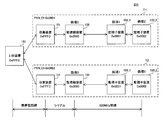
- FIG. 1 is a diagram showing a configuration of a communication system according to an embodiment of the present invention.
- FIG. 2 is a diagram illustrating an application example of the communication system according to the embodiment of the present invention.
- FIG. 3 is a block diagram showing a configuration of the monitoring parent device in the communication system according to the embodiment of the present invention.
- FIG. 4 is a block diagram showing a configuration of the monitor device in the communication system according to the embodiment of the present invention.
- FIG. 5 is a diagram showing an example of address assignment in the communication system according to the embodiment of the present invention.
- FIG. 6 is a diagram illustrating an example of the first list information held by the higher-level device in the communication system according to the embodiment of the present invention.
- FIG. 1 is a diagram showing a configuration of a communication system according to an embodiment of the present invention.
- FIG. 2 is a diagram illustrating an application example of the communication system according to the embodiment of the present invention.
- FIG. 3 is a block diagram showing a configuration of the monitoring parent device
- FIG. 7 is a diagram illustrating an example of the second list information held by the higher-level device in the communication system according to the embodiment of the present invention.
- FIG. 8 is a diagram illustrating an example of the first list information held by the collection device in the communication system according to the embodiment of the present invention.
- FIG. 9 is a diagram illustrating an example of the first list information held by the collection device in the communication system according to the embodiment of the present invention.
- FIG. 10 is a diagram illustrating an example of the second list information held by the collection device, the monitoring parent device, and the monitoring child device in the communication system according to the embodiment of the present invention.
- FIG. 11 is a diagram illustrating an example of the second list information held by the collection device, the monitoring parent device, and the monitoring child device in the communication system according to the embodiment of the present invention.
- FIG. 12 is a diagram illustrating an example of a main part of a packet in the communication system according to the embodiment of the present invention.
- FIG. 13 is a diagram illustrating an example of a packet used between a higher-level device and a collection device in the communication system according to the embodiment of the present invention.
- FIG. 14 is a diagram illustrating an example of a packet used between the collection device and the wireless master device in the communication system according to the embodiment of the present invention.
- FIG. 15 is a diagram illustrating an example of a wireless packet used between monitoring apparatuses in the communication system according to the embodiment of the present invention.
- FIG. 16 is a diagram showing an example of an information transmission sequence in the communication system according to the embodiment of the present invention.
- FIG. 17 is a diagram illustrating an example of a method for transferring wireless packets between monitoring devices in the communication system according to the embodiment of the present invention.
- FIG. 18 is a diagram illustrating an example of a skip setting table held by each monitoring device in the communication system according to the embodiment of the present invention.
- FIG. 19 is a diagram illustrating an example of a skip information table held by each monitoring device in the communication system according to the embodiment of the present invention.
- FIG. 20 is a diagram illustrating an example of a sequence in which the monitoring device in the communication system according to the embodiment of the present invention skips a transfer destination of a wireless packet.
- FIG. 21 is a flowchart that defines an example of an operation procedure when the monitoring device in the communication system according to the embodiment of the present invention transfers a wireless packet.
- FIG. 18 is a diagram illustrating an example of a skip setting table held by each monitoring device in the communication system according to the embodiment of the present invention.
- FIG. 19 is a diagram illustrating an example of a skip information table
- FIG. 22 is a diagram illustrating an example of a process when the monitoring device in the communication system according to the embodiment of the present invention receives a wireless packet having the same content a plurality of times.
- FIG. 23 is a diagram showing an example of the reception history table held by each monitoring device in the communication system according to the embodiment of the present invention.
- FIG. 24 is a diagram illustrating an example of a discard condition table held by each monitoring device in the communication system according to the embodiment of the present invention.
- FIG. 25 is a flowchart illustrating an example of an operation procedure when the monitoring device in the communication system according to the embodiment of the present invention receives a wireless packet.
- each wireless station transmits information to an adjacent wireless station. Thereby, the relay communication is sequentially performed.
- the present disclosure has been made in order to solve the above-described problem, and an object of the present disclosure is to provide a communication system and a monitoring device that can realize more stable operation in a power system.
- a communication system is used in an electric power system and includes a plurality of monitoring devices, wherein different terminal identifiers are fixedly assigned to the plurality of monitoring devices.
- the plurality of monitoring devices are capable of transferring information to another monitoring device having the first terminal identifier registered in advance, and the monitoring device having failed to transfer information to the other monitoring device. Transfers information to another monitoring device having the second terminal identifier registered in advance.
- different terminal identifiers are fixedly assigned to a plurality of monitoring devices, respectively, and the monitoring device transfers information to another monitoring device having a pre-registered terminal identifier. Can be transmitted. Further, when the monitoring device fails to transfer information to another monitoring device having the first terminal identifier, the information is transferred to another monitoring device having the second terminal identifier. Even if a situation occurs in which information cannot be transferred to the monitoring device, the next monitoring device can be skipped and information can be transmitted to other monitoring devices in the next and subsequent stages. Thereby, it is possible to prevent the transfer of the information from being delayed and to transmit the information more reliably. Therefore, more stable operation can be realized in the power system.
- the monitoring device in which the transfer of information to the other monitoring device having the second terminal identifier has failed the other monitoring device having the third terminal identifier registered in advance. Transfer information to
- the monitoring device when information cannot be transferred even if the next monitoring device is skipped, the monitoring device can be skipped and information can be transmitted to another monitoring device, so that the information can be transmitted more reliably. Can be transmitted.
- the monitoring device Preferably, the monitoring device generates a packet including the terminal identifier and the sequence number of the monitoring device as a transmission source and transmits the packet to another monitoring device, and the monitoring device newly receives the packet. If the terminal identifier and the sequence number included in the packet overlap with the terminal identifier and the sequence number included in the received packet, the newly received packet is discarded.
- the monitoring device transfers measurement information indicating a measurement result of the sensor in the monitoring device and transfers measurement information indicating a measurement result of the sensor in the other monitoring device received from another monitoring device. At least one of the following.
- the plurality of monitoring devices include a monitoring parent device that performs multi-hop communication, and a plurality of monitoring child devices that can communicate with the monitoring parent device, and each of the monitoring child devices transmits the monitoring parent device.
- each of the monitoring child devices separately holds the first terminal identifier and the second terminal identifier.
- the first terminal identifier held by each monitor device is exclusive, and in each of the upward direction and the downward direction, each of the monitor devices Are assigned to the monitor devices located at the next stage after the monitor device to which the first terminal identifier is assigned.
- the physically closest monitoring device in the up direction and the down direction along the arrangement direction of the plurality of monitoring devices, the physically closest monitoring device can be set as the first transfer destination, so that when the wireless communication environment deteriorates, The reliability of information transmission can be improved.
- the monitoring device is the monitoring device used in an electric power system and in a communication system including a plurality of monitoring devices, wherein different terminal identifiers are fixedly assigned to the plurality of monitoring devices.
- the storage unit that stores the terminal identifier, and a communication unit that transfers information to another monitoring device having the first terminal identifier registered in advance, the communication unit, If the transfer of the information to another monitoring device fails, the information is transferred to another monitoring device having the previously registered second terminal identifier.
- different terminal identifiers are fixedly assigned to a plurality of monitoring devices, respectively, and the communication unit transfers information to another monitoring device having a pre-registered terminal identifier. Can be transmitted. Further, when the communication unit fails to transfer information to another monitoring device having the first terminal identifier, the communication unit transfers the information to another monitoring device having the second terminal identifier. Even if a situation occurs in which information cannot be transferred to the monitoring device, the next monitoring device can be skipped and information can be transmitted to other monitoring devices in the next and subsequent stages. Thereby, it is possible to prevent the transfer of the information from being delayed and to transmit the information more reliably. Therefore, more stable operation can be realized in the power system.
- FIG. 1 is a diagram showing a configuration of a communication system according to an embodiment of the present invention.
- communication system 301 is a communication system used for an electric power system.
- the communication system 301 is, for example, a communication system attached to a power transmission facility installed between a power plant and a customer of power, and detects, for example, a lightning strike position on the power transmission facility, It is used for temperature monitoring and maintenance of power transmission facilities.
- the communication system 301 includes one or a plurality of monitoring systems T and a host device 181.
- the monitoring system T includes a collection device 151 and one or more monitoring devices 101.
- the communication system 301 includes two monitoring systems T1 and T2 as the monitoring system T.
- the monitoring device 101 has a function of transferring information.
- “transfer” includes, for example, relaying information to a relay destination and transmitting information to a relay destination as a source of information.
- the monitoring apparatus 101 transmits, for example, information received by itself to another monitoring apparatus 101 different from the other monitoring apparatus 101 as “transfer”. Is transmitted to the other monitoring apparatus 101.
- the monitoring device 101 is a device having a wireless communication function.
- the monitoring apparatus 101 performs specific low-power wireless communication using a communication band of, for example, a 920 MHz band.
- the types of the monitoring device 101 include a monitoring parent device 102 having a function as a parent device and a monitoring child device 103 having a function as a child device and performing wireless communication with the monitoring parent device 102.
- the monitoring parent device 102 and the plurality of monitoring child devices 103 perform multi-hop communication.
- the plurality of monitoring devices 101 transmit information serially via a wireless transmission path, that is, are connected in series via a wireless transmission path. That is, in the communication system 301, a plurality of monitoring apparatuses 101 does not constitute a transmission path arranged in parallel or in a mesh, but a wireless transmission path in which the plurality of monitoring apparatuses 101 are arranged in series.
- the monitoring system T includes one monitoring parent device 102 and one or a plurality of monitoring child devices 103.
- the higher-level device 181 is a device that can communicate with the collection device 151.
- the host device 181 can communicate with the collection device 151 via, for example, a mobile phone line.
- the collection device 151 receives the information transmitted from the monitoring parent device 102 and transfers the received information to the higher-level device 181. Further, the collection device 151 receives the information transmitted from the higher-level device 181 and transfers the received information to the monitoring parent device 102.
- the monitor device 103 side as viewed from the host device 181 may be referred to as “downstream side”, and the host device 181 side as viewed from the monitor device 103 may be referred to as “upstream side”.
- the direction from the host device 181 to the monitor device 103 may be referred to as “downward direction”, and the direction from the monitor device 103 to the host device 181 may be referred to as “upward direction”.
- the number of monitoring devices 101 included in the monitoring system T is not particularly limited, and is, for example, 50 or more.
- the monitoring parent device 102 acquires the measurement information indicating the measurement result of the sensor in itself, and transfers the acquired measurement information to the collection device 151.
- the monitoring parent device 102 acquires the measurement information from the monitoring child device 103, and transfers the acquired measurement information to the collection device 151. Further, the monitoring parent device 102 receives setting information and the like from the collection device 151 and transfers the received setting information and the like to the monitoring child device 103.
- the monitor device 103 acquires the measurement information indicating the measurement information of the sensor in itself, and transfers the acquired measurement information to another monitor device 103 or the parent device 102 on the upstream side.
- the monitor device 103 acquires the measurement information from the other monitor device 103 on the downstream side and transfers the acquired measurement information to the other monitor device 103 or the parent device 102 on the upstream side. Further, the monitor device 103 receives setting information and the like from the other monitor device 103 or the parent device 102 on the upstream side, and transfers the received setting information and the like to the other monitor device 103 on the downstream side.
- the collection device 151 and the monitoring device 101 process without transferring the information.
- FIG. 2 is a diagram showing an application example of the communication system according to the embodiment of the present invention.
- a plurality of monitoring devices 101 are installed at different positions in the power system, for example, at a plurality of positions where information necessary for maintenance of the power system can be detected.
- a plurality of monitoring devices 101 are respectively installed in a plurality of steel towers 2 provided in an electric power system.
- the overhead ground wire 3 and the transmission line 4 are installed between the adjacent steel towers 2.
- the monitoring device 101 may be installed in all the towers 2 in the section to be monitored, or may be installed in some of the towers 2 in the section to be monitored.
- the monitoring devices 101 may be installed in, for example, every other, every two, or every third of the plurality of steel towers 2 arranged side by side. In the example shown in FIG. 2, every other monitoring device 101 is installed. Whether to install the monitoring device 101 on all the towers 2 or on some of the towers 2 is determined based on, for example, the installation intervals of the towers 2 and the like.
- the monitoring device 101 is not limited to the tower 2 and may be installed around the tower 2, or may be installed on the power transmission line 4, the overhead ground wire 3 or the ground, for example.
- FIG. 3 is a block diagram showing a configuration of the monitoring parent device in the communication system according to the embodiment of the present invention.
- monitoring parent device 102 includes communication unit 104, battery 106, control unit 107, storage unit 108, and sensor 111.
- the communication unit 104 transmits, to the collection device 151, measurement information indicating the amount of charge measured by the sensor 111 of its own monitoring parent device 102.
- the communication unit 104 and the collection device 151 are, for example, connected by wire, and perform serial communication with each other.
- the battery 106 supplies power to the control unit 107, the sensor 111, the communication unit 104, the storage unit 108, and the like.
- the control unit 107 controls operations of the sensor 111, the communication unit 104, and the like. Specifically, for example, the control unit 107 periodically performs control to turn on the communication unit 104 and turn off the communication unit 104 after a predetermined time has elapsed.
- the sensor 111 measures the charge amount of the overhead ground wire 3 as an example.
- the detection target of the sensor 111 is not particularly limited.
- control unit 107 controls, for example, a switch (not shown). As a result, control is performed to start the power supply from the battery 106 to the sensor 111 and to change the sensor 111 from the off state to the on state.
- the control unit 107 receives the measurement information indicating the amount of charge measured by the sensor 111 and outputs the received measurement information to the communication unit 104. Then, for example, when a predetermined time elapses after the sensor 111 is turned on, the control unit 107 stops power supply from the battery 106 to the sensor 111 by controlling a switch (not shown), for example. Control is performed to make a transition from the on state to the off state.
- the storage unit 108 stores a short address and the like, which will be described later, assigned to its own monitoring parent device 102.
- the collection device 151 transmits the measurement information received from the monitoring parent device 102 to the higher-level device 181.
- the higher-level device 181 receives the measurement information from the collection device 151 and performs various calculations based on the received measurement information. For example, the higher-level device 181 receives measurement information indicating the amount of charge from the plurality of monitoring devices 101 via the collection device 151, and distributes the amount of charge between the plurality of steel towers 2 based on the amount of charge indicated by the received measurement information. Is calculated, and the lightning strike position is estimated based on the calculated distribution of the charge amount.
- FIG. 4 is a block diagram showing a configuration of a monitor device in the communication system according to the embodiment of the present invention.
- monitor device 103 includes communication unit 105, battery 106, control unit 107, storage unit 108, and sensor 111.
- the communication unit 105 transmits measurement information indicating the amount of charge measured by the sensor 111 of its own monitor device 103 to the other monitor device 103 or the parent device 102 on the upstream side.
- the communication unit 105 transfers the received measurement information to the other monitor device 103 or the parent device 102 on the upstream side.
- FIG. 5 is a diagram showing an example of address assignment in the communication system according to the embodiment of the present invention.
- the communication system 301 includes the monitor device 103_1 and the monitor device 103_2 that are the monitor devices 103.
- the monitor device 103_1 and the monitor device 103_2 are installed in this order from the upstream side.
- a first lower layer that is a lower layer in communication between upper device 181 and collection device 151
- a first lower layer that is a lower layer in communication between collection device 151 and monitoring device 101. 2 lower layers.
- communication using, for example, a mobile phone line is performed between the higher-level device 181 and the collection device 151.
- a communication protocol for a mobile phone line for example, IP is used as a first lower layer communication protocol between the higher-level device 181 and the collection device 151.
- serial communication is performed between the collection device 151 and the monitoring parent device 102.
- a communication protocol for serial communication is used as the second lower layer communication protocol between the collection device 151 and the monitoring parent device 102.
- the monitoring parent device 102 and the monitoring child device 103 and between the monitoring child devices 103 for example, specific low-power wireless communication using a 920 MHz communication band in accordance with the communication standard of IEEE 802.15.4 is performed.
- the communication protocol for the specified low-power wireless communication is used as a second lower layer communication protocol between the monitoring parent device 102 and the monitoring child device 103 and between the monitoring child devices 103.
- the upper device 181 stores a first terminal identifier used in the first lower layer, for example, first list information of an IP address in a storage unit (not shown).
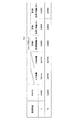
- FIG. 6 is a diagram showing an example of the first list information held by the higher-level device in the communication system according to the embodiment of the present invention.
- first list information TL ⁇ b> 1 indicates a correspondence relationship among PAN_ID, IP address of higher-level device 181, and IP address of collection device 151 for each monitoring system T managed by higher-level device 181.
- the upper device 181 stores a second terminal identifier used in the second lower layer, for example, second list information of a short address in a storage unit (not shown).
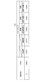
- FIG. 7 is a diagram showing an example of the second list information held by the higher-level device in the communication system according to the embodiment of the present invention.
- the second list information TL2 includes a monitoring system number, a PAN_ID, a short address of the upper device 181 and a short address of the collection device 151 for each monitoring system T managed by the higher device 181.
- the correspondence between the short address and the tower number of the monitoring parent device 102, the short address and the tower number of the monitor device 103_1, and the short address and the tower number of the monitor device 103_2 are shown.
- the monitoring system number and tower number indicate the installation location of the tower.
- the user can designate the monitoring apparatus 101 or the like in a desired tower for the upper apparatus 181 and acquire various information. it can.
- the collection device 151 stores a first terminal identifier used in the first lower layer, for example, first list information of an IP address in a storage unit (not shown).
- the first list information is list information of IP addresses given to the higher-level device 181 and the collection device 151.
- FIG. 8 is a diagram showing an example of the first list information held by the collection device in the communication system according to the embodiment of the present invention.
- FIG. 8 shows an example of the first list information held by the collection device 151 belonging to the monitoring system T1.
- first list information SL1 indicates a correspondence relationship between PAN_ID of monitoring system T1, an IP address of higher-level device 181, and an IP address of collection device 151.
- FIG. 9 is a diagram showing an example of the first list information held by the collection device in the communication system according to the embodiment of the present invention.
- FIG. 9 shows an example of the first list information held by the collection device 151 belonging to the monitoring system T2.
- the first list information SL1 indicates the correspondence between the PAN_ID of the monitoring system T2, the IP address of the higher-level device 181, and the IP address of the collection device 151.
- the collection device 151 stores a second terminal identifier used in the second lower layer, for example, second list information of a short address in a storage unit (not shown).
- the second list information is list information of short addresses given to the higher-level device 181, the collection device 151, the monitoring parent device 102, and the monitoring child device 103.
- FIG. 10 is a diagram showing an example of the second list information held by the collection device and the monitoring device in the communication system according to the embodiment of the present invention.
- FIG. 10 illustrates an example of the second list information held by the collection device 151, the monitoring parent device 102, and the monitoring child device 103 belonging to the monitoring system T1.
- second list information SL2 includes a monitoring system number, a PAN_ID, a short address of higher-level device 181, a short address of collection device 151, and a short address of monitoring parent device 102 of monitoring system T1. It shows a correspondence relationship between the short address and the tower number, the short address and the tower number of the monitor device 103_1, and the short address and the tower number of the monitor device 103_2.
- FIG. 11 is a diagram showing an example of the second list information held by the collection device and the monitoring device in the communication system according to the embodiment of the present invention.
- FIG. 11 illustrates an example of the second list information held by the collection device 151, the monitoring parent device 102, and the monitoring child device 103 belonging to the monitoring system T2.
- second list information SL2 includes a monitoring system number, a PAN_ID, a short address of higher-level device 181, a short address of collection device 151, and a short address of monitoring parent device 102 of monitoring system T2. It shows a correspondence relationship between the short address and the tower number, the short address and the tower number of the monitor device 103_1, and the short address and the tower number of the monitor device 103_2.
- different first terminal identifiers for example, IP addresses are fixedly assigned to the collection device 151 and the higher-level device 181, respectively.
- Different second terminal identifiers for example, short addresses are fixedly assigned to the collection device 151, the monitoring parent device 102, the monitoring child device 103, and the higher-level device 181, respectively.
- PAN_ID Personal Area Network Identification
- the monitoring parent device 102, the plurality of monitoring child devices 103, the collection device 151, and the higher-level device 181 are configured to use a second terminal identifier as a source address and a destination address, for example, a source short address and a destination short address. Transmit and receive the stored packets.
- FIG. 12 is a diagram showing an example of a main part of a packet in the communication system according to the embodiment of the present invention.
- a packet transmitted between higher-level device 181 and collection device 151 includes a TCP / IP header, a routing header, an application header, and an application payload.
- the TCP / IP header and the routing header are used for lower layer communication, and the application header and application payload are used for upper layer communication.
- the packet may include data other than the contents shown in FIG.
- the host device 181 can recognize the contents of the application header and the application payload.
- the collection device 151 cannot recognize the contents of the application header and the application payload.
- the packet transmitted between the collection device 151 and the monitoring parent device 102 includes a serial header, a routing header, an application header, and an application payload.
- the serial header and the routing header are used for lower layer communication, and the application header and application payload are used for upper layer communication.
- the collection device 151 and the monitoring parent device 102 can recognize the contents of the serial header and the routing header, but cannot recognize the contents of the application header and the application payload.
- the packet transmitted between the monitoring parent device 102 and the monitoring child device 103 is a wireless packet, and includes a wireless header, a routing header, an application header, and an application payload.
- the radio header and the routing header are used for lower layer communication, and the application header and application payload are used for upper layer communication.
- the monitoring parent device 102 and the monitoring child device 103 can recognize the contents of the radio header and the routing header, but cannot recognize the contents of the application header and the application payload.
- the packet transmitted between the monitor devices 103 is a wireless packet, and includes a wireless header, a routing header, an application header, and an application payload.
- the radio header and the routing header correspond to the lower layer
- the application header and the application payload correspond to the upper layer.
- the monitor device 103 can recognize the contents of the radio header and the routing header, but cannot recognize the contents of the application header and the application payload.
- FIG. 13 is a diagram illustrating an example of a packet used between the higher-level device and the collection device in the communication system according to the embodiment of the present invention.
- FIG. 13 shows the format of an IP packet.
- the IP packet includes a TCP / IP header and a routing packet stored in the payload.
- the TCP / IP header includes, for example, a "destination IP address" and a "source IP address”.
- the routing packet includes, for example, a routing header and an application packet stored in the payload.
- the routing header includes, for example, “destination PAN_ID”, “source PAN”, “destination short address”, and “source short address”.
- the application packet includes, for example, an application header and an application payload.
- the application payload contains target information such as measurement information.
- the target information includes, for example, information used for maintenance of a power system such as a power transmission facility.
- the target information includes, for example, measurement information indicating the amount of electric charge used for detecting the position of the lightning strike on the power transmission equipment, and the temperature used for monitoring the temperature of the transmission line 4.
- the target information includes, for example, measurement information indicating the amount of electric charge used for detecting the position of the lightning strike on the power transmission equipment, and the temperature used for monitoring the temperature of the power transmission line 4. Measurement information, or measurement information indicating the inclination of the transmission line 4 due to slack or the like.
- the target information is, for example, measurement information indicating the amount of charge used to detect the position of the lightning strike on the power transmission equipment, and is used for monitoring the temperature of the overhead ground wire 3. It includes measurement information indicating the temperature, measurement information indicating the inclination of the overhead ground wire 3 due to slack, and the like.
- the target information is, for example, measurement information indicating the inclination of the ground, measurement information indicating the vibration of the ground, or indicating the depth of snow on the ground. Includes measurement information and the like.
- the detection target of the sensor 111 and the type of the sensor 111 in the monitoring device 101 are appropriately set according to the type of the target information.
- FIG. 14 is a diagram showing an example of a packet used between the collection device and the wireless master device in the communication system according to the embodiment of the present invention.
- FIG. 14 shows a format of a serial packet transmitted by serial communication.
- the serial packet includes a serial header and a routing packet stored in the payload.
- the serial header is a header used for serial communication.
- the routing packet has the same contents as the routing packet shown in FIG.
- FIG. 15 is a diagram showing an example of a wireless packet used between monitoring apparatuses in the communication system according to the embodiment of the present invention.
- FIG. 15 shows a format of a wireless packet transmitted by 920 MHz specific low-power wireless communication.
- the wireless packet includes a wireless header and a routing packet stored in the payload.
- the wireless header is a header used for specific low-power wireless communication.
- the routing packet is different from the routing packet shown in FIG. 13 in that a sequence number is added to a routing header.
- the sequence number basically differs for each wireless packet.
- the monitoring apparatus 101 retransmits a wireless packet, the same sequence number is assigned to the wireless packet before and after the retransmission.
- Each device in the communication system 301 includes a computer including a memory, and an arithmetic processing unit such as a CPU in the computer reads a program including a part or all of each step of the following sequence diagram or flowchart from the memory, respectively. Execute.
- Each of the programs of the plurality of devices can be externally installed. The programs of the plurality of devices are distributed while being stored in a recording medium.
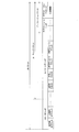
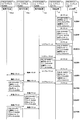
- FIG. 16 is a diagram showing an example of an information transmission sequence in the communication system according to the embodiment of the present invention.
- FIG. 16 shows eight transmission examples 1 to 8 of a packet in the host device 181 and the monitoring system T1, that is, between the host device 181, the collection device 151, the monitoring parent device 102, and the two monitoring child devices 103_1 and 103_2. The example which is performed in order is shown.
- the higher-level device 181 transmits an IP packet including the setting information of the collection device 151 to the collection device 151.
- This IP packet includes “0x0001” as the destination PAN_ID, “192.168.1.3” as the destination IP address, “192.168.1.2” as the source IP address, and "0xFFFD” is included as the destination short address, and "0xFFFE” is included as the source short address.
- This IP packet does not include the source PAN_ID.
- the collection device 151 receives and processes the IP packet from the higher-level device 181.
- the collection device 151 transmits an IP packet including measurement information and the like to the higher-level device 181.
- This IP packet includes “0x0001” as the source PAN_ID, “192.168.1.2” as the destination IP address, “192.168.1.3” as the source IP address, and “0xFFFE” is included as the destination short address, and “0xFFFD” is included as the source short address.
- This IP packet does not include the destination PAN_ID.
- the higher-level device 181 receives and processes the IP packet from the collection device 151.
- the higher-level device 181 transmits an IP packet including setting information of the monitoring parent device 102 to the collection device 151.
- This IP packet includes “0x0001” as the destination PAN_ID, “192.168.1.3” as the destination IP address, “192.168.1.2” as the source IP address, and It includes “0x0000” as the destination short address and “0xFFFE” as the source short address. This IP packet does not include the source PAN_ID.
- the collection device 151 deletes the TCP / IP header of the received IP packet, creates a serial packet by adding a serial header, and monitors the created serial packet. Send to parent device 102.
- This serial packet includes “0x0001” as the destination PAN_ID, “0x0000” as the destination short address, and “0xFFFE” as the source short address. This serial packet does not include the source PAN_ID.
- the monitoring parent device 102 receives and processes the serial packet from the collection device 151.
- the monitoring parent device 102 transmits a serial packet including measurement information and the like to the collection device 151.
- This serial packet includes “0x0001” as the source PAN_ID, “0xFFFE” as the destination short address, and “0x0000” as the source short address. This serial packet does not include the destination PAN_ID.
- the collection device 151 when the collection device 151 receives the serial packet from the monitoring parent device 102, it deletes the serial header of the received serial packet and adds a TCP / IP header to create an IP packet. This is transmitted to the host device 181.
- This IP packet includes “0x0001” as the source PAN_ID, “0xFFFE” as the destination short address, and “0x0000” as the source short address. This IP packet does not include the destination PAN_ID.
- the higher-level device 181 receives and processes the IP packet from the collection device 151.
- the higher-level device 181 transmits an IP packet including setting information of the monitor device 103_2 to the collection device 151.
- This IP packet includes “0x0001” as the destination PAN_ID, “192.168.1.3” as the destination IP address, “192.168.1.2” as the source IP address, and It includes “0x0002” as the destination short address and “0xFFFE” as the source short address. This IP packet does not include the source PAN_ID.
- the collection device 151 deletes the TCP / IP header of the received IP packet, creates a serial packet by adding a serial header, and monitors the created serial packet. Send to parent device 102.
- This serial packet includes “0x0001” as the destination PAN_ID, “0x0002” as the destination short address, and “0xFFFE” as the source short address. This serial packet does not include the source PAN_ID.
- the monitoring parent device 102 deletes the serial header of the received serial packet, adds a wireless header to create a wireless packet, and monitors the created wireless packet as a monitor. Transmit to the device 103_1.
- the wireless packet includes “0x0001” as the destination PAN_ID, “0x0001” as the destination wireless address, “0x0000” as the source wireless address, “0x0002” as the destination short address, and "0xFFFE” is included as the short address. This wireless packet does not include the source PAN_ID.
- the monitor child device 103_1 upon receiving the wireless packet from the monitoring parent device 102, deletes the wireless header of the received wireless packet, and creates and creates a new wireless packet by adding a new wireless header.
- the wireless packet is transmitted to the monitor device 103_2.
- the wireless packet includes “0x0001” as the destination PAN_ID, “0x0002” as the destination wireless address, “0x0001” as the source wireless address, “0x0002” as the destination short address, and "0xFFFE" is included as the short address.
- This wireless packet does not include the source PAN_ID.
- the monitor device 103_2 receives and processes the wireless packet from the monitor device 103_1.
- monitor device 103_2 transmits a wireless packet including measurement information and the like to monitor device 103_1.
- the wireless packet includes “0x0001” as the source PAN_ID, “0x0001” as the destination wireless address, “0x0002” as the source wireless address, “0xFFFE” as the destination short address, and “0x0002” is included as the short address. This wireless packet does not include the destination PAN_ID.
- the monitor child device 103_1 upon receiving the wireless packet from the monitor child device 103_2, the monitor child device 103_1 deletes the wireless header of the received wireless packet, and creates and creates a new wireless packet by adding a new wireless header.
- the wireless packet is transmitted to the monitoring parent device 102.
- the wireless packet includes “0x0001” as the source PAN_ID, “0x0000” as the destination wireless address, “0x0001” as the source wireless address, “0xFFFE” as the destination short address, and “0x0002” is included as the short address. This wireless packet does not include the destination PAN_ID.
- the monitoring parent device 102 when the monitoring parent device 102 receives a wireless packet from the monitoring child device 103_1, the monitoring parent device 102 deletes a wireless header of the received wireless packet, adds a serial header to create a serial packet, and collects the created serial packet. Transmit to the device 151.
- This serial packet includes “0x0001” as the source PAN_ID, “0xFFFE” as the destination short address, and “0x0002” as the source short address. This serial packet does not include the destination PAN_ID.
- the collection device 151 when the collection device 151 receives the serial packet from the monitoring parent device 102, it deletes the serial header of the received serial packet and adds a TCP / IP header to create an IP packet. This is transmitted to the host device 181.
- This IP packet includes “0x0001” as the source PAN_ID, “192.168.1.2” as the destination IP address, “192.168.1.3” as the source IP address, and "0xFFFE” is included as the destination short address, and "0x0002" is included as the source short address.
- This IP packet does not include the destination PAN_ID.
- the higher-level device 181 receives and processes the IP packet from the collection device 151.
- the monitoring parent device 102 transmits a wireless packet including information for setting the monitoring child device 103_2 to the monitoring child device 103_1.
- This wireless packet includes “0x0001” as the destination PAN_ID, “0x0001” as the source PAN_ID, “0x0001” as the destination wireless address, “0x0000” as the source wireless address, and the destination short-circuit.
- the address includes “0x0002” and the source short address includes “0x0000”.
- the monitor child device 103_1 upon receiving the wireless packet from the monitoring parent device 102, deletes the wireless header of the received wireless packet, and creates and creates a new wireless packet by adding a new wireless header.
- the wireless packet is transmitted to the monitor device 103_2.
- the wireless packet includes “0x0001” as the destination PAN_ID, “0x0001” as the source PAN_ID, “0x0002” as the destination wireless address, “0x0001” as the source wireless address, and the destination short-circuit.
- the address includes “0x0002” and the source short address includes “0x0000”.
- the monitor device 103_2 receives and processes the wireless packet from the monitor device 103_1.
- the monitor device 103_2 transmits a wireless packet including information such as measurement information to the monitor device 103_1.
- This wireless packet includes “0x0001” as the destination PAN_ID, “0x0001” as the source PAN_ID, “0x0001” as the destination wireless address, “0x0002” as the source wireless address, and the destination short-circuit.
- the address includes “0x0000” and the source short address includes “0x0002”.
- the monitor child device 103_1 upon receiving the wireless packet from the monitor child device 103_2, the monitor child device 103_1 deletes the wireless header of the received wireless packet, and creates and creates a new wireless packet by adding a new wireless header.
- the wireless packet is transmitted to the monitoring parent device 102.
- This wireless packet includes “0x0001” as the destination PAN_ID, “0x0001” as the source PAN_ID, “0x0000” as the destination wireless address, “0x0001” as the source wireless address, and the destination short-circuit.
- the address includes “0x0000” and the source short address includes “0x0002”.
- the monitoring parent device 102 receives and processes the wireless packet from the monitoring child device 103_1.
- the packet transmitted between the devices includes the PAN_ID.
- the host device 181 can recognize the error.
- the communication system 301 may have a configuration in which a packet transmitted between the devices does not include the PAN_ID.
- FIG. 17 is a diagram showing an example of a method of transferring wireless packets between monitoring devices in the communication system according to the embodiment of the present invention.
- the five monitoring devices 101 that is, the monitoring device 101_0, the monitoring device 101_1, the monitoring device 101_2, the monitoring device 101_3, and the monitoring device 101_4 are arranged in this order in series.
- the direction from the monitoring device 101_0 to the monitoring device 101_4 may be an upward direction or a downward direction.
- the monitoring device 101 shown in FIG. 17 is the monitoring parent device 102 shown in FIG. 3 or the monitoring child device 103 shown in FIG.
- the monitoring device 101_0 may be the monitoring parent device 102
- the monitoring devices 101_1 to 101_4 may be the monitoring child devices 103
- the monitoring devices 101_0 to 101_4 may be the monitoring child devices 103
- the device 101_4 may be the monitoring parent device 102
- the monitoring devices 101_0 to 101_3 may be the monitoring child devices 103.
- each of the communication unit 104 and the communication unit 105 is also referred to as a communication unit 50.
- communication unit 50 changes the destination short address when retransmitting the wireless packet. Specifically, the communication unit 50 changes the destination short address in the routing header of the wireless packet to the short address of the monitoring device 101 that is one or more destinations of the monitoring device 101 having the destination short address.
- the communication unit 50 stores the destination short address and the transmission source short address in the radio header, and stores the transmission destination short address and the transmission destination short address in the routing header.
- a wireless packet storing a source short address and a sequence number is created, and the wireless packet is transmitted.
- the communication unit 50 When the communication unit 50 receives a wireless packet from another monitoring apparatus 101, the communication unit 50 stores the received wireless packet in the storage unit 108.
- a terminal identifier specifically, a short address is assigned to each of the five monitoring devices 101 in advance.
- the short addresses assigned to the monitoring devices 101_0, 101_1, 101_2, 101_3, and 101_4 are, for example, 0x0000, 0x0001, 0x0002, 0x0003, and 0x0004, respectively.
- the communication unit 50 in each monitoring device 101 can transfer a wireless packet to another monitoring device 101 having a first short address registered in advance in itself, for example, in each of the upward direction and the downward direction.
- the first short address is a short address of another monitoring device 101 at the next stage and subsequent, for example, a short address of the monitoring device 101 at the next stage.
- the communication unit 50 in each monitoring device 101 transfers the wireless packet to the next monitoring device 101, that is, the next monitoring device 101.
- the monitoring device 101_0 having the short address of 0x0000 transfers the wireless packet to the monitoring device 101_1 having the short address of 0x0001.
- the monitoring device 101_1 receives the wireless packet from the monitoring device 101_0, and transfers the wireless packet to the monitoring device 101_2 whose short address is 0x0002.
- the communication unit 50 of the monitoring device 101_1 deletes the wireless header of the wireless packet received from the monitoring device 101_0.
- the communication unit 50 of the monitoring device 101_1 creates a new wireless packet by referring to the second list information SL2 shown in FIG. 10 or 11 and adding a wireless header whose transmission destination short address is 0x0002. Then, the communication unit 50 in the monitoring device 101_1 transfers the created wireless packet to the monitoring device 101_2.
- the communication unit 50 in each monitoring device 101 has a second short address stored in advance when the transfer of the information to the other monitoring device 101 fails in, for example, each of the up direction and the down direction.
- the information is transferred to another monitoring device 101 having the second short address, for example, the next monitoring device 101 at the next stage.
- the second short address is, for example, the short address of the monitoring device 101 in the next stage. That is, for example, in each of the upward direction and the downward direction, the second short address held by the monitoring device 101 is a monitoring device 101 located at a stage subsequent to the monitoring device 101 to which the first short address is assigned, for example, It is assigned to the monitoring device 101 located at the next stage. That is, when the transfer of information to another monitoring device 101 has failed, the monitoring device 101 skips the transfer destination of the wireless packet.
- the communication unit 50 in each monitoring device 101 transfers the wireless packet to the next monitoring device 101 when the transfer of the wireless packet to the next monitoring device 101 fails.
- the second short address held by the monitoring device 101 may be the monitoring device 101 located next to the monitoring device 101 to which the first short address is assigned.
- the monitoring device 101 may be located one after the other.
- the communication unit 50 in each monitoring device 101 causes the third short-circuit stored beforehand to be stored therein.
- the information is transferred to another monitoring apparatus 101 having an address, for example, another monitoring apparatus 101 at the next and subsequent stages.
- the third short address is, for example, the short address of the next monitoring device 101 in the next stage. That is, for example, in each of the upward direction and the downward direction, the third short address held by the monitoring device 101 is allocated to the monitoring device 101 located next to the monitoring device 101 to which the second short address is allocated. I have. That is, when the transfer of information to the other monitoring device 101 of the skip destination has failed, the monitoring device 101 further skips the transfer destination of the wireless packet.
- the communication unit 50 in each monitoring device 101 transfers the wireless packet to the next monitoring device 101 after the next.
- the communication unit 50 in the monitoring device 101_2 transfers the wireless packet to the monitoring device 101_4.
- FIG. 18 is a diagram showing an example of a skip setting table held by each monitoring device in the communication system according to the embodiment of the present invention.
- skip setting table Tbs includes information related to the skip operation.
- Information related to the skip operation is, for example, the allowable standby time Tmax, the allowable number of retransmissions Sdmax, the allowable skip number Skmax, and the initial skip number.
- the storage unit 108 in each monitoring device 101 stores a skip setting table Tbs.
- the permissible standby time Tmax is the maximum time during which a wireless packet can be transferred and then waited until a wireless packet indicating ACK (Acknowledgment) is received from the transfer destination monitoring apparatus 101.
- the communication unit 50 of the monitoring device 101 of the transmission source determines that the transfer of the wireless packet has failed when the allowable standby time Tmax has elapsed.
- the wireless packet indicating ACK may be simply referred to as “ACK”.
- the allowable number of retransmissions Sdmax is the maximum number of times that the transfer can be retried when the communication unit 50 of the monitoring apparatus 101 determines that the transfer has failed.
- the communication unit 50 of the monitoring apparatus 101 of the transmission source determines that the transfer of the wireless packet has failed, the communication unit 50 retries the transfer, that is, retransmits the wireless packet with the allowable number of retransmissions Sdmax as an upper limit.
- the permissible skip number Skmax is the maximum number that can skip the monitoring apparatus 101.
- the allowable skip number Skmax depends on the number of the monitoring devices 101 up to the terminal monitoring device 101 in the transmission direction of the wireless packet when viewed from the monitoring device 101.
- the initial skip number Sk1 is an initial value of the skip number.
- the initial skip number Sk1 is set to, for example, 0.
- the direction from monitoring device 101_4 to monitoring device 101_0 is the upward direction
- the direction from monitoring device 101_0 to monitoring device 101_4 is the downward direction.
- the monitoring devices 101_1 to 101_4 are the monitoring child devices 103 and the monitoring device 101_0 is the monitoring parent device 102.
- each monitoring device 101 holds one or a plurality of short addresses separately in the up direction and the down direction.
- the storage unit 108 of each monitoring device 101 has an address area for holding one or a plurality of short addresses separately in the upward direction and the downward direction, and a flag area indicating the validity of the short address in the address area. ing.
- the monitoring device 101_4 located at the start point in the up direction holds the first short address, the second short address, and the third short address in the up direction. Further, the monitoring device 101_4 located at the end point in the down direction does not hold the first short address, the second short address, and the third short address in the down direction.
- the address area in the storage unit 108 of the monitoring apparatus 101_4 includes three stored areas for storing the first short address, the second short address, and the third short address in the upward direction, respectively, and a short address added. And a plurality of unstored areas that can be stored.
- the flag area in the storage unit 108 of the monitoring device 101_4 has three areas respectively corresponding to the three stored areas described above, and a plurality of areas corresponding to the plurality of unstored areas described above. A flag “1” indicating that the corresponding short address is valid is stored in each of the three areas. On the other hand, a flag "0" indicating that the corresponding short address is not stored or the corresponding short address is invalid is stored in the plurality of areas.
- the monitoring device 101_3 located next to the start point in the up direction holds the first short address, the second short address, and the third short address in the up direction.
- the monitoring device 101_3 located in a stage preceding the end point in the down direction holds the first short address in the down direction, and does not hold the second short address and the third short address in the down direction.
- the address area in the storage unit 108 of the monitoring apparatus 101_3 includes four address areas for storing the first short address, the second short address, and the third short address in the upward direction, and the first short address in the downward direction, respectively. It has a stored area and a plurality of unstored areas in which a short address can be additionally stored.
- the flag area in the storage unit 108 of the monitoring device 101_3 has four areas respectively corresponding to the four stored areas described above, and a plurality of areas corresponding to the plurality of unstored areas described above. A flag "1" indicating that the corresponding short address is valid is stored in each of the four areas. On the other hand, a flag "0" indicating that the corresponding short address is not stored or the corresponding short address is invalid is stored in the plurality of areas.
- the monitoring device 101_2 located two steps before the end point in the up direction holds the first short address and the second short address in the up direction, and holds the third short address in the up direction. Absent. Further, the monitoring device 101_2 located two stages before the end point in the down direction holds the first short address and the second short address in the down direction, and holds the third short address in the down direction. Absent.
- the address area in the storage unit 108 of the monitoring device 101_2 includes four first and second short addresses for the upward direction, and four first and second short addresses for the downward direction. It has a stored area and a plurality of unstored areas in which a short address can be additionally stored.
- the flag area in the storage unit 108 of the monitoring device 101_2 has four areas respectively corresponding to the four stored areas described above, and a plurality of areas corresponding to the plurality of unstored areas described above. A flag "1" indicating that the corresponding short address is valid is stored in each of the four areas. On the other hand, a flag "0" indicating that the corresponding short address is not stored or the corresponding short address is invalid is stored in the plurality of areas.
- the monitoring device 101_1 located before the end point in the up direction holds the first short address in the up direction, and does not hold the second short address and the third short address in the up direction. Further, the monitoring apparatus 101_1 located at the next stage of the start point in the down direction holds the first short address, the second short address, and the third short address in the down direction.
- the address area in the storage unit 108 of the monitoring apparatus 101_1 includes four first areas for storing the first short address in the upward direction, and first, second and third short addresses in the downward direction. It has a stored area and a plurality of unstored areas in which a short address can be additionally stored.
- the flag area in the storage unit 108 of the monitoring device 101_1 has four areas respectively corresponding to the four stored areas described above, and a plurality of areas corresponding to the plurality of unstored areas described above.
- a flag "1" indicating that the corresponding short address is valid is stored in each of the four areas.
- a flag "0" indicating that the corresponding short address is not stored or the corresponding short address is invalid is stored in the plurality of areas.
- the monitoring device 101_0 located at the end point in the up direction does not hold the first short address, the second short address, and the third short address in the up direction.
- the monitoring device 101_0 located at the start point in the down direction holds the first short address, the second short address, and the third short address in the down direction.
- the address area in the storage unit 108 of the monitoring apparatus 101_0 is obtained by adding three stored areas for storing the first short address, the second short address, and the third short address in the down direction, respectively, and adding the short address. And a plurality of unstored areas that can be stored.
- the flag area in the storage unit 108 of the monitoring device 101_0 has three areas respectively corresponding to the three stored areas described above, and a plurality of areas respectively corresponding to the plurality of unstored areas described above.
- a flag “1” indicating that the corresponding short address is valid is stored in each of the three areas.
- a flag "0" indicating that the corresponding short address is not stored or the corresponding short address is invalid is stored in the plurality of areas.
- the first short address of each monitoring device 101 that holds the first short address is exclusive, that is, different from each other.
- the second short address of each monitoring device 101 that holds the second short address is exclusive, that is, different from each other.
- the third short address of each monitoring device 101 that holds the third short address is exclusive, that is, different from each other.
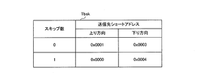
- FIG. 19 is a diagram showing an example of a skip information table held by each monitoring device in the communication system according to the embodiment of the present invention.
- FIG. 19 illustrates an example of a skip information table held by the monitoring apparatus 101_2.
- skip information table Tbsk indicates the correspondence between the number of skips and the short address of another monitoring device 101 in each of the upward direction and the downward direction. For example, a skip number of 0 corresponds to the short address of the next monitoring device 101, that is, the next monitoring device 101, and a skip number of 1 corresponds to the short address of the next monitoring device 101, that is, the next monitoring device 101. are doing.
- the storage unit 108 in each monitoring device 101 stores a skip information table Tbsk.
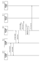
- FIG. 20 is a diagram showing an example of a sequence in which the monitoring device in the communication system according to the embodiment of the present invention skips a transfer destination of a wireless packet.
- monitoring apparatus 101_0 transfers a wireless packet to monitoring apparatus 101_1 (step S101).
- the monitoring device 101_1 transmits an ACK to the monitoring device 101_0 (step S103).
- the monitoring apparatus 101_1 transfers the wireless packet to the monitoring apparatus 101_2 (step S105).
- the monitoring device 101_2 transmits an ACK to the monitoring device 101_1 (step S107).
- the monitoring device 101_2 transfers the wireless packet to the monitoring device 101_3 (step S109).
- the monitoring device 101_2 retransmits the wireless packet to the monitoring device 101_3 (step S111).
- the monitoring device 101_2 stops the transfer of the packet to the monitoring device 101_3, and changes the transfer destination of the wireless packet to the monitoring device 101_4. That is, the monitoring apparatus 101_2 skips one transfer destination of the wireless packet (step S113).
- the monitoring device 101_2 transfers the wireless packet to the monitoring device 101_4 (step S114).
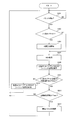
- FIG. 21 is a flowchart that defines an example of an operation procedure when the monitoring device in the communication system according to the embodiment of the present invention transfers a wireless packet.
- the monitoring device 101 an operation when the monitoring device 101_2 in FIG. 20 uses the skip information table Tbsk illustrated in FIG. 19 will be described.
- communication unit 50 in monitoring apparatus 101_2 transfers the wireless packet to monitoring apparatus 101 at the next stage. Specifically, the communication unit 50 receives a wireless packet including the short address and the sequence number of the monitoring device 101_0 as a transmission source from the monitoring device 101_1, and transfers the wireless packet to the next-stage monitoring device 101_3 in the downstream direction. (Step S201).
- the communication unit 50 checks whether an ACK has been received from the monitoring device 101_3 (step S203).
- the communication unit 50 When the communication unit 50 receives the ACK from the monitoring device 101_3 (YES in step S203), the communication unit 50 ends the wireless packet transfer process.
- the communication unit 50 checks whether or not the allowable standby time Tmax has elapsed since the wireless packet was transferred (step S205).
- the communication unit 50 waits until an ACK is received from the monitoring device 101_3 (step S203).
- the communication unit 50 determines whether the number of retransmissions of the wireless packet, that is, the number of transfer retries is equal to or less than the allowable number of retransmissions Sdmax Confirm that.
- the allowable number of retransmissions Sdmax is, for example, one (step S207).
- the communication unit 50 retransmits the wireless packet (step S201).
- the communication unit 50 checks whether the skip number is equal to or less than the allowable number of skips Skmax (step S209).
- the communication unit 50 stops the wireless packet transfer process.
- the communication unit 50 updates the skip number by adding 1 to the current skip number (step S211).
- the communication unit 50 changes the transfer destination of the wireless packet. Specifically, the communication unit 50 refers to the skip information table Tbsk and changes the destination short address in the routing header of the wireless packet to the short address corresponding to the updated skip number, thereby performing the current transfer.
- the first monitoring device 101 is set as a new transfer destination (step S213).
- the communication unit 50 performs the skip in the uplink transfer.
- the operation of skipping the transfer destination of the wireless packet with reference to the information table Tbsk is the same.
- the communication unit 50 may return the skip number to the initial value 0 after the elapse of a predetermined time after transmitting the wireless packet, or may not return the skip number to the initial value 0.
- FIG. 22 is a diagram illustrating an example of a process when the monitoring device in the communication system according to the embodiment of the present invention receives a wireless packet having the same content a plurality of times.
- three monitoring devices 101_0, 101_1, and 101_2 are representatively illustrated.
- communication unit 50 in monitoring device 101_0 transfers a wireless packet to monitoring device 101_1 (step S401).
- the communication unit 50 in the monitoring device 101_1 transmits an ACK to the monitoring device 101_0 (step S403).
- the communication unit 50 in the monitoring device 101_1 transfers the wireless packet to the monitoring device 101_2 (step S405).
- the communication unit 50 in the monitoring device 101_2 transmits an ACK to the monitoring device 101_1 (step S407).
- the communication unit 50 of the monitoring apparatus 101_0 cannot receive an ACK within the allowable standby time Tmax after transferring the wireless packet to the monitoring apparatus 101_1, the communication unit 50 retransmits the wireless packet to the monitoring apparatus 101_1 (step S409).
- the communication unit 50 in the monitoring device 101_1 transmits an ACK to the monitoring device 101_0 (step S411).
- the communication unit 50 in the monitoring device 101_0 cannot receive an ACK within the allowable standby time Tmax after transferring the wireless packet to the monitoring device 101_1, the communication unit 50 changes the transfer destination of the wireless packet, One transfer destination is skipped (step S413).
- the communication unit 50 in the monitoring device 101_0 transfers the wireless packet to the monitoring device 101_2 (step S415).
- the communication unit 50 in the monitoring device 101_2 transmits an ACK to the monitoring device 101_0 (step S417).
- the communication unit 50 in the monitoring device 101_2 discards the wireless packet received from the monitoring device 101_0. Specifically, when the short address and the sequence number included in the newly received wireless packet overlap with the short address and the sequence number included in the received wireless packet, respectively, the monitoring device 101_2 determines that the newly received wireless packet Is discarded (step S419).
- FIG. 23 is a diagram showing an example of the reception history table held by each monitoring device in the communication system according to the embodiment of the present invention.
- reception history table Tbh1 includes information on the reception history of wireless packets.
- the information of the reception history of the wireless packet is, for example, the source short address, the sequence number, and the number of times of reception of the duplicate packet.
- the storage unit 108 in each monitoring device 101 stores the reception history table Tbh1.
- the number of times of reception of the duplicate packet is the number of times the monitoring apparatus 101 has received a wireless packet having the same source short address and the same sequence number.
- FIG. 24 is a diagram showing a discard condition table held by each monitoring device in the communication system according to the embodiment of the present invention.
- discard condition table Tbh2 includes allowable number of receptions Rmax and update time T2max.
- the storage unit 108 in each monitoring device 101 stores a discard condition table Tbh2.
- FIG. 25 is a flowchart showing an example of an operation procedure when the monitoring device in the communication system according to the embodiment of the present invention receives a wireless packet.
- FIG. 25 illustrates the operation of the monitoring apparatus 101_2 in FIG.
- communication unit 50 in monitoring apparatus 101_2 waits until a wireless packet is received from another monitoring apparatus 101_1 (NO in step S301).
- the communication unit 50 determines whether the same wireless packet has been received before the received wireless packet, that is, whether the received wireless packet has been received. It is determined whether or not the packet is the first wireless packet (step S303).
- the communication unit 50 starts measuring an elapsed time after receiving the wireless packet (step S305).
- An ACK is transmitted to the monitoring device 101_1 (step S307).
- the communication unit 50 transmits an ACK to the other monitoring device 101 that is the transfer source. For example, when receiving a wireless packet from the monitoring device 101_1, the communication unit 50 transmits an ACK to the monitoring device 101_1 (step S307).
- the communication unit 50 stores the source address and the sequence number of the received wireless packet in the storage unit 108.
- the monitoring apparatus 101_2 stores the source short address 0x0000 and the sequence number 001 of the received wireless packet in the reception history table Tbh1 in the storage unit 108 (Step S309).
- the communication unit 50 determines whether or not the elapsed time after receiving the first wireless packet is equal to or less than the update time T2max (step S311).
- the communication unit 50 deletes the transmission source short address and the sequence number corresponding to the received wireless packet from the reception history table Tbh1 (step S313).
- the communication unit 50 determines that the number of times of reception of the duplicate packet, which is a wireless packet whose source short address and sequence number overlap, respectively, is the allowable number of receptions Rmax It is determined whether or not the above is true (step S315).
- the communication unit 50 waits until a new wireless packet is received (step S301).
- the communication unit 50 deletes the duplicate packet from the storage unit 108 (step S317).
- the monitoring device 101 sets the short address and the sequence number included in the newly received wireless packet to the short address and the sequence number included in the received wireless packet, respectively.
- a configuration is adopted in which newly received wireless packets are discarded, but this is not a limitation.
- the monitoring apparatus 101 transmits the newly received wireless packet even if the short address and sequence number included in the newly received wireless packet overlap with the short address and sequence number included in the received wireless packet.
- a configuration in which the information is not discarded may be used.
- the monitoring device 101 is provided with the sensor 111, but the present invention is not limited to this.
- the sensor 111 may be provided outside the monitoring device 101.
- the sensor 111 transmits information indicating the measurement result to the monitoring device 101 by wire communication or wireless communication.
- the communication system according to the embodiment of the present invention may have a configuration in which some of the plurality of monitoring devices 101 include the sensor 111.
- a configuration may be adopted in which some of the plurality of monitoring devices 101 include the sensor 111, and other monitoring devices 101 do not include the sensor 111.
- the sensor 111 may be provided outside the monitoring device 101 having no sensor 111, and the sensor 111 may transmit measurement information indicating a measurement result to the monitoring device 101.
- the monitoring apparatus 101 without the sensor 111 may be configured to transfer information from another monitoring apparatus 101 to another monitoring apparatus 101 without being a source of information.
- one of the transfer of the wireless packet in the uplink and the transfer of the wireless packet in the downlink may be performed. Good.
- each monitoring device 101 is configured to separately hold one or a plurality of short addresses in the upward direction and the downward direction, but the present invention is not limited to this. At least some of the monitoring devices 101 may hold one or more short addresses only in the upward direction, or at least some of the monitoring devices 101 may hold one or more short addresses only in the downward direction. A configuration for holding the information may be used.
- the monitoring apparatus 101 is configured to hold one or a plurality of short addresses only in the upward direction
- the following configuration may be employed. That is, for example, when a packet is received from another downstream monitoring device 101, the monitoring device 101 stores the transmission source short address included in the received packet in the storage unit 108. Then, when transmitting the packet in the downstream direction, the monitoring apparatus 101 generates a packet using the stored source short address as the destination short address.
- the monitoring device 101 holds one or a plurality of short addresses only in the downward direction
- the following configuration may be adopted. That is, for example, when receiving a packet from another monitoring apparatus 101 on the upstream side, the monitoring apparatus 101 stores the transmission source short address included in the received packet in the storage unit 108. Then, when transmitting the packet in the upward direction, the monitoring apparatus 101 generates a packet using the stored source short address as the destination short address.
- the communication system 301 is a communication system that is used in a power system and includes a plurality of monitoring devices 101. Different short addresses are fixedly assigned to the plurality of monitoring devices 101, respectively.
- the plurality of monitoring devices 101 can transfer information to another monitoring device 101 having a first short address registered in advance.
- the monitoring device 101 that has failed to transfer information to the other monitoring device 101 transfers the information to another monitoring device 101 having a second short address registered in advance.
- a different short address is fixedly assigned to each of the plurality of monitoring devices 101, and the monitoring device 101 transfers information to another monitoring device 101 having a short address registered in advance. Can transmit information.
- the monitoring apparatus 101 fails to transfer information to the other monitoring apparatus 101 having the first short address, the information is transferred to the other monitoring apparatus 101 having the second short address. Even if a situation occurs in which information cannot be transferred to the next-stage monitoring apparatus 101, the next-stage monitoring apparatus 101 can be skipped and information can be transmitted to other monitoring apparatuses 101 at the next and subsequent stages. Thereby, it is possible to prevent the transfer of the information from being delayed and to transmit the information more reliably.
- the monitoring device 101 that has failed to transfer information to another monitoring device 101 having the second short address has the third short address registered in advance. , And transfers the information to another monitoring apparatus 101.
- the monitoring device 101 is further skipped and information is transmitted to other monitoring devices in the next and subsequent stages. Can be transmitted. Thereby, information can be transmitted more reliably.
- monitoring apparatus 101 In the communication system according to the embodiment of the present invention, monitoring apparatus 101 generates a wireless packet including its own short address and a sequence number as a transmission source, and transmits the generated wireless packet to another monitoring apparatus 101. If the short address and the sequence number included in the newly received packet overlap with the short address and the sequence number included in the received wireless packet, the monitoring device 101 discards the newly received wireless packet.
- monitoring device 101 transfers measurement information indicating a measurement result of sensor 111 in monitoring device 101 and receives a sensor from other monitoring device 101 in another monitoring device 101. At least one of the transfer of the measurement information indicating the measurement result of step 111 is performed.
- the plurality of monitoring devices 101 include a monitoring parent device 102 performing multi-hop communication, and a plurality of monitoring child devices 103 capable of communicating with the monitoring parent device 102.
- each monitor child device 103 has a first short address and a second short address. Short addresses are separately stored.
- the first short address held by each monitor device 103 is exclusive.
- the second short address held by each monitor device 103 is allocated to the monitor device 103 located at a stage subsequent to the monitor device 103 to which the first short address is allocated. Have been.
- the physically closest monitoring device 101 can be set as the first transfer destination in the up direction and the down direction along the arrangement direction of the plurality of monitoring devices 101, so that the wireless communication environment is degraded. In this case, the reliability of information transmission can be increased.
- the monitoring device 101 is a monitoring device in a communication system 301 that is used in a power system and includes a plurality of monitoring devices 101. Different terminal identifiers are fixedly assigned to the plurality of monitoring devices 101, respectively.
- the monitoring device 101 includes a storage unit 108 that stores a terminal identifier, and a communication unit 50 that transfers information to another monitoring device 101 having the first terminal identifier registered in advance. When the transfer of the information to the other monitoring device 101 has failed, the communication unit 50 transfers the information to the other monitoring device 101 having the second terminal identifier registered in advance.
- a terminal identifier different from that of another monitoring device 101 is fixedly assigned, and the communication unit 50 transfers information to another monitoring device 101 having a terminal identifier registered in advance. Can transmit information. Further, when the communication unit 50 fails to transfer information to the other monitoring device 101 having the first terminal identifier, the communication unit 50 transfers information to the other monitoring device 101 having the second terminal identifier. Even if a situation occurs in which information cannot be transferred to the next-stage monitoring apparatus 101, the next-stage monitoring apparatus 101 can be skipped and information can be transmitted to other monitoring apparatuses 101 at the next and subsequent stages. Thereby, it is possible to prevent the transfer of the information from being delayed and to transmit the information more reliably. Therefore, more stable operation can be realized in the power system.
- the plurality of monitoring apparatuses 101 transmit information in series via a wireless transmission path.
- a communication system used for a power system and including a plurality of monitoring devices The plurality of monitors are installed in a plurality of towers, respectively, and transfer at least one of the measurement information received from another monitoring device or measurement information indicating a measurement result of a sensor in the monitoring device, Different terminal identifiers are respectively fixedly assigned to the plurality of monitoring devices, The plurality of monitoring devices have a first terminal identifier registered in advance, and can transfer information to the other monitoring devices in the next and subsequent stages, The communication system, wherein the monitoring device that has failed to transfer information to the other monitoring device transfers information to another monitoring device next to the next stage having the second terminal identifier registered in advance.
Landscapes
- Engineering & Computer Science (AREA)
- Computer Networks & Wireless Communication (AREA)
- Signal Processing (AREA)
- Power Engineering (AREA)
- Mobile Radio Communication Systems (AREA)
- Remote Monitoring And Control Of Power-Distribution Networks (AREA)
- Telephonic Communication Services (AREA)
Abstract
通信システムは、電力系統に用いられ、複数の監視装置を備える通信システムであって、前記複数の監視装置にそれぞれ異なる端末識別子が固定的に割り当てられており、前記複数の監視装置は、予め登録された第1の前記端末識別子を有する他の前記監視装置へ情報を転送可能であり、前記他の監視装置への情報の転送が失敗した前記監視装置は、予め登録された第2の前記端末識別子を有する他の前記監視装置へ情報を転送する。
Description
本発明は、通信システムおよび監視装置に関する。
この出願は、2018年7月25日に出願された日本出願特願2018-139465号を基礎とする優先権を主張し、その開示のすべてをここに取り込む。
この出願は、2018年7月25日に出願された日本出願特願2018-139465号を基礎とする優先権を主張し、その開示のすべてをここに取り込む。
ネットワークシステムの一例として、たとえば、特許第6046480号公報(特許文献1)には、以下のような構成が開示されている。
すなわち、ネットワークシステムは、送電線を架設する鉄塔列の各鉄塔に無線局を設置すると共に、少なくとも1台の該無線局に外部通信回線に接続可能な親局を接続して、これらの無線局により該鉄塔列に沿って、該無線局から該親局に、又は該親局から該無線局に、双方向に情報を順次中継可能であり、該無線局が、該鉄塔列の一方側から送られた該情報を記憶するための第1の通信用メモリと、該鉄塔列の他方側から送られた該情報を記憶するための第2の通信用メモリとを備え、該第1の通信用メモリに記憶された該情報を該他方側に中継し、該第2の通信用メモリに記憶された該情報を該一方側に中継する送電鉄塔保守情報無線ネットワークシステムにおいて、該無線局には個別に識別番号が付与されており、該情報の発信元になる該無線局が該情報に自局の該識別番号を付して送信するものであり、該親局が該無線局の該識別番号と、その無線局の設置されている該鉄塔に付与された鉄塔番号とを対応させた識別番号変換テーブルを有しており、該鉄塔に複数の送電線路が併架されていて、同一の該鉄塔に各送電線路に対応する複数の該鉄塔番号が付与され、該親局が、該識別番号変換テーブルに基づいて、該情報を発信した該無線局の識別番号を、各々の該送電線路に対応する複数の該鉄塔番号に変換する。親局は、携帯電話回線等の外部通信回線を介して、上位ホスト局と通信を行う。
(1)本開示の通信システムは、電力系統に用いられ、複数の監視装置を備える通信システムであって、前記複数の監視装置にそれぞれ異なる端末識別子が固定的に割り当てられており、前記複数の監視装置は、予め登録された第1の前記端末識別子を有する他の前記監視装置へ情報を転送可能であり、前記他の監視装置への情報の転送が失敗した前記監視装置は、予め登録された第2の前記端末識別子を有する他の前記監視装置へ情報を転送する。
(6)本開示の監視装置は、電力系統に用いられ、複数の監視装置を備える通信システムにおける前記監視装置であって、前記複数の監視装置にそれぞれ異なる端末識別子が固定的に割り当てられており、前記端末識別子を記憶する記憶部と、予め登録された第1の前記端末識別子を有する他の前記監視装置へ情報を転送する通信部とを備え、前記通信部は、前記他の監視装置への情報の転送が失敗した場合、予め登録された第2の前記端末識別子を有する他の前記監視装置へ情報を転送する。
本開示の一態様は、このような特徴的な処理部を備える通信システムとして実現され得るだけでなく、かかる特徴的な処理をステップとする方法として実現され得たり、かかるステップをコンピュータに実行させるためのプログラムとして実現され得る。また、本開示の一態様は、通信システムの一部または全部を実現する半導体集積回路として実現され得る。
また、本開示の一態様は、このような特徴的な処理部を備える監視装置として実現され得るだけでなく、かかる特徴的な処理をステップとする方法として実現され得たり、かかるステップをコンピュータに実行させるためのプログラムとして実現され得る。また、本開示の一態様は、監視装置の一部または全部を実現する半導体集積回路として実現され得る。
[本開示が解決しようとする課題]
特許文献1に記載のネットワークシステムにおいては、各無線局は、隣接する無線局に情報を送信する。これにより、逐次リレー通信が行われる。
特許文献1に記載のネットワークシステムにおいては、各無線局は、隣接する無線局に情報を送信する。これにより、逐次リレー通信が行われる。
このような特許文献1に記載の技術を超えて、安定した運用を実現することが可能な技術が望まれる。
本開示は、上述の課題を解決するためになされたもので、その目的は、電力系統において、より安定した運用を実現することが可能な通信システムおよび監視装置を提供することである。
[本開示の効果]
本開示によれば、電力系統において、より安定した運用を実現することができる。
本開示によれば、電力系統において、より安定した運用を実現することができる。
[本願発明の実施形態の説明]
最初に、本発明の実施形態の内容を列記して説明する。
最初に、本発明の実施形態の内容を列記して説明する。
(1)本発明の実施の形態に係る通信システムは、電力系統に用いられ、複数の監視装置を備える通信システムであって、前記複数の監視装置にそれぞれ異なる端末識別子が固定的に割り当てられており、前記複数の監視装置は、予め登録された第1の前記端末識別子を有する他の前記監視装置へ情報を転送可能であり、前記他の監視装置への情報の転送が失敗した前記監視装置は、予め登録された第2の前記端末識別子を有する他の前記監視装置へ情報を転送する。
このように、複数の監視装置にそれぞれ異なる端末識別子が固定的に割り当てられ、監視装置が、予め登録された端末識別子を有する他の監視装置へ情報を転送する構成により、簡単な構成で情報を伝送することができる。また、監視装置が第1の端末識別子を有する他の監視装置への情報の転送に失敗した場合、第2の端末識別子を有する他の監視装置へ情報を転送する構成により、たとえば、次段の監視装置への情報の転送ができない事態が生じても、次段の監視装置をスキップして次段以降の他の監視装置へ情報を伝送することができる。これにより、情報の転送が滞ることを防止して、より確実に情報を伝送することができる。したがって、電力系統において、より安定した運用を実現することができる。
(2)好ましくは、前記第2の端末識別子を有する前記他の監視装置への情報の転送が失敗した前記監視装置は、予め登録された第3の前記端末識別子を有する、他の前記監視装置へ情報を転送する。
このような構成により、たとえば、次段の監視装置をスキップしても情報の転送ができない場合に当該監視装置をスキップして他の監視装置へ情報を伝送することができるため、より確実に情報を伝送することができる。
(3)好ましくは、前記監視装置は、送信元として前記監視装置の前記端末識別子、およびシーケンス番号を含むパケットを生成して他の前記監視装置へ送信し、前記監視装置は、新たに受信した前記パケットに含まれる前記端末識別子および前記シーケンス番号が、受信済みの前記パケットに含まれる前記端末識別子および前記シーケンス番号とそれぞれ重複する場合、前記新たに受信した前記パケットを破棄する。
このような構成により、たとえば、パケットの再送によって複数の監視装置から同じ内容のパケットが転送され、監視装置間において多数の不要なパケットが伝送されることを防止することができる。
(4)好ましくは、前記監視装置は、前記監視装置におけるセンサの計測結果を示す計測情報の転送および他の前記監視装置から受信した前記他の監視装置におけるセンサの計測結果を示す計測情報の転送の少なくともいずれか一方を行う。
このような構成により、センサの計測結果を示す計測情報の転送が滞ることを防止して、より確実に計測情報を伝送することができる。したがって、たとえば電力系統において、送電設備への雷撃位置等を示す情報をより確実に伝送することができる。
(5)好ましくは、前記複数の監視装置は、マルチホップ通信を行う、監視親装置と、前記監視親装置と通信可能な複数の監視子装置とを含み、各前記監視子装置から前記監視親装置への上り方向、および前記監視親装置から前記各監視子装置への下り方向の各々について、前記各監視子装置は、前記第1の端末識別子および前記第2の端末識別子を別個に保持しており、前記上り方向および前記下り方向の各々において、前記各監視子装置が保持する前記第1の端末識別子は排他的であり、前記上り方向および前記下り方向の各々において、前記各監視子装置が保持する前記第2の端末識別子は、前記第1の端末識別子の割り当てられた前記監視子装置の次段以降に位置する前記監視子装置に割り当てられている。
このような構成により、複数の監視装置の配列方向に沿った上り方向および下り方向において、物理的に最も近い監視装置を最初の転送先とすることができるため、無線通信環境が悪化した場合における情報伝送の確実性を高めることができる。
(6)本発明の実施の形態に係る監視装置は、電力系統に用いられ、複数の監視装置を備える通信システムにおける前記監視装置であって、前記複数の監視装置にそれぞれ異なる端末識別子が固定的に割り当てられており、前記端末識別子を記憶する記憶部と、予め登録された第1の前記端末識別子を有する他の前記監視装置へ情報を転送する通信部とを備え、前記通信部は、前記他の監視装置への情報の転送が失敗した場合、予め登録された第2の前記端末識別子を有する他の前記監視装置へ情報を転送する。
このように、複数の監視装置にそれぞれ異なる端末識別子が固定的に割り当てられ、通信部が、予め登録された端末識別子を有する他の監視装置へ情報を転送する構成により、簡単な構成で情報を伝送することができる。また、通信部が第1の端末識別子を有する他の監視装置への情報の転送に失敗した場合、第2の端末識別子を有する他の監視装置へ情報を転送する構成により、たとえば、次段の監視装置への情報の転送ができない事態が生じても、次段の監視装置をスキップして次段以降の他の監視装置へ情報を伝送することができる。これにより、情報の転送が滞ることを防止して、より確実に情報を伝送することができる。したがって、電力系統において、より安定した運用を実現することができる。
以下、本発明の実施の形態について図面を用いて説明する。なお、図中同一または相当部分には同一符号を付してその説明は繰り返さない。また、以下に記載する実施の形態の少なくとも一部を任意に組み合わせてもよい。
[構成および基本動作]
図1は、本発明の実施の形態に係る通信システムの構成を示す図である。
図1は、本発明の実施の形態に係る通信システムの構成を示す図である。
図1を参照して、通信システム301は、電力系統に用いられる通信システムである。具体的には、通信システム301は、たとえば、発電所および電力の需要家間に設置される送電設備に併設される通信システムであって、たとえば、送電設備への雷撃位置の検出、送電線の温度監視、および送電設備の保守等に用いられる。
通信システム301は、1または複数の監視系統Tと、上位装置181とを備える。監視系統Tは、収集装置151と、1または複数の監視装置101とを含む。図1に示される例では、通信システム301は、監視系統Tとして2つの監視系統T1,T2を備えている。
監視装置101は、情報を転送する機能を有する。本明細書において、「転送」は、たとえば、情報を中継先へ中継すること、および、情報の送信元として情報を中継先へ送信することを含む。
具体的には、監視装置101は、「転送」として、たとえば、自己が他の監視装置101から受信した情報を当該他の監視装置101とは異なる他の監視装置101へ送信し、また、自己におけるセンサ111の計測結果を示す情報を他の監視装置101へ送信する。
監視装置101は、無線通信機能を有する装置である。監視装置101は、たとえば、920MHz帯の通信帯域を用いる特定小電力無線通信を行う。
監視装置101の種類には、親機としての機能を有する監視親装置102と、子機としての機能を有し、監視親装置102と無線通信を行う監視子装置103とがある。監視親装置102および複数の監視子装置103は、マルチホップ通信を行う。
監視装置101が複数設けられている場合、複数の監視装置101は、無線伝送路を介して情報を直列的に伝送する、すなわち、無線伝送路を介して直列接続される。つまり、通信システム301では、複数の監視装置101が並列的またはメッシュ状に配置された伝送路を構成するのでななく、複数の監視装置101が直列的に配置された無線伝送路を構成する。この場合、監視系統Tは、1つの監視親装置102と、1または複数の監視子装置103とを含む。
上位装置181は、収集装置151と通信可能な装置である。上位装置181は、たとえば、携帯電話回線を介して収集装置151と通信することができる。
収集装置151は、監視親装置102から送信された情報を受信し、受信した情報を上位装置181へ転送する。また、収集装置151は、上位装置181から送信された情報を受信し、受信した情報を監視親装置102へ転送する。
以下、上位装置181から見て監視子装置103側を「下流側」と称し、監視子装置103から見て上位装置181側を「上流側」と称する場合がある。また、上位装置181から監視子装置103への方向を「下り方向」と称し、監視子装置103から上位装置181への方向を「上り方向」と称する場合がある。
監視系統Tに含まれる監視装置101の数は特に限定されるものではなく、たとえば50以上である。
監視親装置102は、自己におけるセンサの計測結果を示す計測情報を取得し、取得した計測情報を収集装置151へ転送する。
また、監視親装置102は、監視子装置103からの計測情報を取得し、取得した計測情報を収集装置151へ転送する。また、監視親装置102は、収集装置151から設定情報等を受信し、受信した設定情報等を監視子装置103へ転送する。
監視子装置103は、自己におけるセンサの計測情報を示す計測情報を取得し、取得した計測情報を上流側の他の監視子装置103または監視親装置102へ転送する。
また、監視子装置103は、下流側の他の監視子装置103からの計測情報を取得し、取得した計測情報を上流側の他の監視子装置103または監視親装置102へ転送する。また、監視子装置103は、上流側の他の監視子装置103または監視親装置102から設定情報等を受信し、受信した設定情報等を下流側の他の監視子装置103へ転送する。
なお、収集装置151および監視装置101は、受信した情報が自己宛である場合、当該情報を転送せずに処理する。
図2は、本発明の実施の形態に係る通信システムの適用例を示す図である。
図2を参照して、電力系統における異なる位置、たとえば、電力系統の保守に必要な情報を検出可能な複数の位置に、複数の監視装置101がそれぞれ設置される。具体的には、たとえば、電力系統に設けられた複数の鉄塔2に複数の監視装置101がそれぞれ設置される。架空地線3および送電線4は、隣り合う鉄塔2の間に架設される。
なお、監視装置101は、監視対象となる区間のすべての鉄塔2に設置されてもよいし、監視対象となる区間の一部の鉄塔2に設置されてもよい。
具体的には、監視装置101は、並んで設置された複数の鉄塔2において、たとえば、1つおき、2つおき、または3つおきに設置されてもよい。図2に示される例では、監視装置101は、1つおきに設置されている。監視装置101をすべての鉄塔2に設置するか、または一部の鉄塔2に設置するかは、たとえば鉄塔2の設置間隔等に基づいて決定される。
また、監視装置101は、鉄塔2に限らず、鉄塔2の周辺に設置されてもよいし、たとえば、送電線4、架空地線3または地面等に設置されてもよい。
図3は、本発明の実施の形態に係る通信システムにおける監視親装置の構成を示すブロック図である。
図3を参照して、監視親装置102は、通信部104と、電池106と、制御部107と、記憶部108と、センサ111とを備える。
通信部104は、自己の監視親装置102のセンサ111が測定した電荷量を示す計測情報を収集装置151へ送信する。通信部104および収集装置151は、たとえば、有線接続されており、互いにシリアル通信を行う。
電池106は、制御部107、センサ111、通信部104および記憶部108等へ電力を供給する。
制御部107は、センサ111および通信部104等の動作を制御する。具体的には、たとえば、制御部107は、通信部104をオンし、かつ所定時間が経過すると通信部104をオフする制御を周期的に行う。
センサ111は、一例として、架空地線3の電荷量を計測する。なお、センサ111の検知対象は特に限定されるものではない。
また、制御部107は、落雷が予想されるエリア、および落雷が予想される期間等を示す所定情報を通信部104および収集装置151経由で上位装置181から受信すると、たとえば図示しないスイッチを制御することにより、電池106からセンサ111への電力供給を開始してセンサ111をオフ状態からオン状態へ遷移させる制御を行う。
制御部107は、センサ111で測定された電荷量を示す計測情報を受けて、受けた計測情報を通信部104へ出力する。そして、制御部107は、たとえばセンサ111をオン状態に遷移させてから所定時間が経過すると、たとえば図示しないスイッチを制御することにより、電池106からセンサ111への電力供給を停止してセンサ111をオン状態からオフ状態へ遷移させる制御を行う。
記憶部108は、自己の監視親装置102に割り当てられた後述するショートアドレス等を記憶する。
再び図1を参照して、収集装置151は、監視親装置102から受信した計測情報を上位装置181へ送信する。
上位装置181は、収集装置151から計測情報を受信し、受信した計測情報に基づいて種々の演算を行う。たとえば、上位装置181は、複数の監視装置101から電荷量を示す計測情報を収集装置151経由で受信し、受信した各計測情報の示す電荷量に基づいて複数の鉄塔2間における電荷量の分布を算出し、算出した電荷量の分布に基づいて雷撃位置を推定する。
図4は、本発明の実施の形態に係る通信システムにおける監視子装置の構成を示すブロック図である。
図4を参照して、監視子装置103は、通信部105と、電池106と、制御部107と、記憶部108と、センサ111とを備える。
通信部105は、自己の監視子装置103のセンサ111が測定した電荷量を示す計測情報を上流側の他の監視子装置103または監視親装置102へ送信する。また、通信部105は、下流側に位置する監視子装置103から電荷量を示す計測情報を受信した場合、受信した計測情報を上流側の他の監視子装置103または監視親装置102へ転送する。
図5は、本発明の実施の形態に係る通信システムにおけるアドレス割り当ての一例を示す図である。以下では、通信システム301が、監視子装置103である監視子装置103_1および監視子装置103_2を備える場合について説明する。監視子装置103_1および監視子装置103_2は、上流側からこの順番で設置される。
図5を参照して、通信システム301では、上位装置181および収集装置151間の通信における下位レイヤである第1の下位レイヤと、収集装置151および監視装置101間の通信における下位レイヤである第2の下位レイヤとが異なる。
具体的には、上位装置181および収集装置151間では、たとえば携帯電話回線を用いた通信が行われる。上位装置181および収集装置151間では、第1の下位レイヤの通信プロトコルとして、携帯電話回線用の通信プロトコル、たとえばIPが用いられる。
一方、収集装置151および監視親装置102間では、たとえばシリアル通信が行われる。収集装置151および監視親装置102間では、第2の下位レイヤの通信プロトコルとして、シリアル通信用の通信プロトコルが用いられる。
また、監視親装置102および監視子装置103間、ならびに監視子装置103間では、たとえば、IEEE802.15.4の通信規格に従う、920MHz帯の通信帯域を用いる特定小電力無線通信が行われる。監視親装置102および監視子装置103間、ならびに監視子装置103間では、第2の下位レイヤの通信プロトコルとして、当該特定小電力無線通信用の通信プロトコルが用いられる。
上位装置181は、第1の下位レイヤにおいて用いられる第1端末識別子、たとえばIPアドレスの第1リスト情報を図示しない記憶部に保持する。
図6は、本発明の実施の形態に係る通信システムにおける上位装置が保持する第1リスト情報の一例を示す図である。
図6を参照して、第1リスト情報TL1は、上位装置181が管理する監視系統Tごとの、PAN_IDと、上位装置181のIPアドレスと、収集装置151のIPアドレスとの対応関係を示す。
また、上位装置181は、第2の下位レイヤにおいて用いられる第2端末識別子、たとえばショートアドレスの第2リスト情報を図示しない記憶部に保持する。
図7は、本発明の実施の形態に係る通信システムにおいて、上位装置が保持する第2リスト情報の一例を示す図である。
図7を参照して、第2リスト情報TL2は、上位装置181が管理する監視系統Tごとの、監視系統番号と、PAN_IDと、上位装置181のショートアドレスと、収集装置151のショートアドレスと、監視親装置102のショートアドレスおよび鉄塔番号と、監視子装置103_1のショートアドレスおよび鉄塔番号と、監視子装置103_2のショートアドレスおよび鉄塔番号との対応関係を示す。
監視系統番号および鉄塔番号が、鉄塔の設置場所を示す。これにより、ユーザは、たとえば上位装置181へ監視系統番号および鉄塔番号を入力することにより、上位装置181に対して所望の鉄塔における監視装置101等を指定し、各種情報の取得等を行うことができる。
収集装置151は、第1の下位レイヤにおいて用いられる第1端末識別子、たとえばIPアドレスの第1リスト情報を図示しない記憶部に保持する。
具体的には、たとえば、第1リスト情報は、上位装置181および収集装置151に付与されたIPアドレスのリスト情報である。
図8は、本発明の実施の形態に係る通信システムにおける収集装置が保持する第1リスト情報の一例を示す図である。図8は、監視系統T1に属する収集装置151が保持する第1リスト情報の一例を示している。
図8を参照して、第1リスト情報SL1は、監視系統T1の、PAN_IDと、上位装置181のIPアドレスと、収集装置151のIPアドレスとの対応関係を示す。
図9は、本発明の実施の形態に係る通信システムにおける収集装置が保持する第1リスト情報の一例を示す図である。図9は、監視系統T2に属する収集装置151が保持する第1リスト情報の一例を示す。
図9を参照して、第1リスト情報SL1は、監視系統T2の、PAN_IDと、上位装置181のIPアドレスと、収集装置151のIPアドレスとの対応関係を示す。
また、収集装置151は、第2の下位レイヤにおいて用いられる第2端末識別子、たとえばショートアドレスの第2リスト情報を図示しない記憶部に保持する。
具体的には、たとえば、第2リスト情報は、上位装置181、収集装置151、監視親装置102および監視子装置103に付与されたショートアドレスのリスト情報である。
図10は、本発明の実施の形態に係る通信システムにおける収集装置および監視装置が保持する第2リスト情報の一例を示す図である。図10は、監視系統T1に属する収集装置151、監視親装置102および監視子装置103が保持する第2リスト情報の一例を示している。
図10を参照して、第2リスト情報SL2は、監視系統T1の、監視系統番号と、PAN_IDと、上位装置181のショートアドレスと、収集装置151のショートアドレスと、監視親装置102のショートアドレスおよび鉄塔番号と、監視子装置103_1のショートアドレスおよび鉄塔番号と、監視子装置103_2のショートアドレスおよび鉄塔番号との対応関係を示す。
図11は、本発明の実施の形態に係る通信システムにおける収集装置および監視装置が保持する第2リスト情報の一例を示す図である。図11は、監視系統T2に属する収集装置151、監視親装置102および監視子装置103が保持する第2リスト情報の一例を示している。
図11を参照して、第2リスト情報SL2は、監視系統T2の、監視系統番号と、PAN_IDと、上位装置181のショートアドレスと、収集装置151のショートアドレスと、監視親装置102のショートアドレスおよび鉄塔番号と、監視子装置103_1のショートアドレスおよび鉄塔番号と、監視子装置103_2のショートアドレスおよび鉄塔番号との対応関係を示す。
上記のように、通信システム301では、収集装置151および上位装置181にそれぞれ異なる第1端末識別子、たとえばIPアドレスが固定的に割り当てられている。
また、収集装置151、監視親装置102、監視子装置103および上位装置181にそれぞれ異なる第2端末識別子、たとえばショートアドレスが固定的に割り当てられている。
また、監視系統T1,T2にそれぞれ異なるネットワーク識別子、たとえばPAN_ID(Personal Area Network Identification)が固定的に割り当てられている。
通信システム301において、監視親装置102、複数の監視子装置103、収集装置151および上位装置181は、送信元アドレスおよび送信先アドレスとして第2端末識別子、たとえば、送信元ショートアドレスおよび送信先ショートアドレスがそれぞれ格納されたパケットを送受信する。
図12は、本発明の実施の形態に係る通信システムにおけるパケットの要部の一例を示す図である。
図12を参照して、上位装置181と収集装置151との間で伝送されるパケットは、TCP/IPヘッダ、ルーティングヘッダ、アプリケーションヘッダおよびアプリケーションペイロードを含む。TCP/IPヘッダおよびルーティングヘッダは下位レイヤの通信に用いられ、アプリケーションヘッダおよびアプリケーションペイロードは上位レイヤの通信に用いられる。なお、当該パケットは、図12に示す内容以外のデータを含んでもよい。
上位装置181は、アプリケーションヘッダおよびアプリケーションペイロードの内容を認識することができる。一方、収集装置151は、アプリケーションヘッダおよびアプリケーションペイロードの内容を認識することができない。
収集装置151と監視親装置102との間で伝送されるパケットは、シリアルヘッダ、ルーティングヘッダ、アプリケーションヘッダおよびアプリケーションペイロードを含む。シリアルヘッダおよびルーティングヘッダは下位レイヤの通信に用いられ、アプリケーションヘッダおよびアプリケーションペイロードは上位レイヤの通信に用いられる。
収集装置151および監視親装置102は、シリアルヘッダおよびルーティングヘッダの内容を認識することができる一方で、アプリケーションヘッダおよびアプリケーションペイロードの内容を認識することができない。
監視親装置102と監視子装置103との間で伝送されるパケットは、無線パケットであり、無線ヘッダ、ルーティングヘッダ、アプリケーションヘッダおよびアプリケーションペイロードを含む。無線ヘッダおよびルーティングヘッダは下位レイヤの通信に用いられ、アプリケーションヘッダおよびアプリケーションペイロードは上位レイヤの通信に用いられる。
監視親装置102および監視子装置103は、無線ヘッダおよびルーティングヘッダの内容を認識することができる一方で、アプリケーションヘッダおよびアプリケーションペイロードの内容を認識することができない。
監視子装置103間で伝送されるパケットは、無線パケットであり、無線ヘッダ、ルーティングヘッダ、アプリケーションヘッダおよびアプリケーションペイロードを含む。無線ヘッダおよびルーティングヘッダは下位レイヤに対応し、アプリケーションヘッダおよびアプリケーションペイロードは上位レイヤに対応する。
監視子装置103は、無線ヘッダおよびルーティングヘッダの内容を認識することができる一方で、アプリケーションヘッダおよびアプリケーションペイロードの内容を認識することができない。
図13は、本発明の実施の形態に係る通信システムにおける、上位装置および収集装置間で使用されるパケットの一例を示す図である。図13には、IPパケットのフォーマットが示されている。
図13を参照して、IPパケットは、TCP/IPヘッダと、ペイロードに格納されたルーティングパケットとを含む。
TCP/IPヘッダは、たとえば、「送信先IPアドレス」および「送信元IPアドレス」を含む。
ルーティングパケットは、たとえば、ルーティングヘッダと、ペイロードに格納されたアプリケーションパケットとを含む。
ルーティングヘッダは、たとえば、「送信先PAN_ID」、「送信元PAN」、「送信先ショートアドレス」および「送信元ショートアドレス」を含む。
アプリケーションパケットは、たとえば、アプリケーションヘッダおよびアプリケーションペイロードを含む。
アプリケーションペイロードは、計測情報等の対象情報を含む。対象情報は、たとえば、送電設備等の電力系統の保守に用いられる情報等を含む。詳細には、監視装置101が鉄塔2に設置される場合、対象情報は、たとえば、送電設備への雷撃位置の検出に用いられる電荷量を示す計測情報、送電線4の温度監視に用いられる温度を示す計測情報、鉄塔2の傾きを示す計測情報、または地面上の積雪の深さを示す計測情報等を含む。
また、監視装置101が送電線4に設置される場合、対象情報は、たとえば、送電設備への雷撃位置の検出に用いられる電荷量を示す計測情報、送電線4の温度監視に用いられる温度を示す計測情報、または送電線4の弛み等による傾きを示す計測情報等を含む。
また、監視装置101が架空地線3に設置される場合、対象情報は、たとえば、送電設備への雷撃位置の検出に用いられる電荷量を示す計測情報、架空地線3の温度監視に用いられる温度を示す計測情報、または架空地線3の弛み等による傾きを示す計測情報等を含む。
また、監視装置101が鉄塔2の周辺の地面に設置される場合、対象情報は、たとえば、地面の傾きを示す計測情報、地面の振動を示す計測情報、または地面上の積雪の深さを示す計測情報等を含む。
監視装置101におけるセンサ111の検知対象およびセンサ111の種類は、上記対象情報の種類に応じて適宜設定される。
図14は、本発明の実施の形態に係る通信システムにおける、収集装置および無線親装置間で使用されるパケットの一例を示す図である。図14には、シリアル通信により伝送されるシリアルパケットのフォーマットが示されている。
図14を参照して、シリアルパケットは、シリアルヘッダと、ペイロードに格納されたルーティングパケットとを含む。
シリアルヘッダは、シリアル通信に用いられるヘッダである。ルーティングパケットは、図13に示すルーティングパケットと同じ内容である。
図15は、本発明の実施の形態に係る通信システムにおける監視装置間で使用される無線パケットの一例を示す図である。図15には、920MHzの特定小電力無線通信により伝送される無線パケットのフォーマットが示されている。
図15を参照して、無線パケットは、無線ヘッダと、ペイロードに格納されたルーティングパケットとを含む。
無線ヘッダは、特定小電力無線通信に用いられるヘッダである。ルーティングパケットは、図13に示すルーティングパケットと比べて、ルーティングヘッダにシーケンス番号が追加されている点が異なっている。
シーケンス番号は、基本的には無線パケットごとに異なる。なお、監視装置101が無線パケットを再送する場合には、再送前後の無線パケットにおいて同じシーケンス番号が付与される。
[動作の流れ]
通信システム301における各装置は、メモリを含むコンピュータを備え、当該コンピュータにおけるCPU等の演算処理部は、以下のシーケンス図またはフローチャートの各ステップの一部または全部を含むプログラムを当該メモリからそれぞれ読み出して実行する。これら複数の装置のプログラムは、それぞれ、外部からインストールすることができる。これら複数の装置のプログラムは、それぞれ、記録媒体に格納された状態で流通する。
通信システム301における各装置は、メモリを含むコンピュータを備え、当該コンピュータにおけるCPU等の演算処理部は、以下のシーケンス図またはフローチャートの各ステップの一部または全部を含むプログラムを当該メモリからそれぞれ読み出して実行する。これら複数の装置のプログラムは、それぞれ、外部からインストールすることができる。これら複数の装置のプログラムは、それぞれ、記録媒体に格納された状態で流通する。
図16は、本発明の実施の形態に係る通信システムにおける情報伝送のシーケンスの一例を示す図である。
図16は、上位装置181および監視系統T1における、すなわち上位装置181、収集装置151、監視親装置102、および2つの監視子装置103_1,103_2の間におけるパケットの8つの伝送例1~8がこの順番で実行される例を示している。
下り方向へ情報を伝送する伝送例1において、上位装置181は、収集装置151の設定情報を含むIPパケットを収集装置151へ送信する。
このIPパケットは、送信先PAN_IDとして「0x0001」を含み、送信先IPアドレスとして「192.168.1.3」を含み、送信元IPアドレスとして「192.168.1.2」を含み、送信先ショートアドレスとして「0xFFFD」を含み、送信元ショートアドレスとして「0xFFFE」を含む。このIPパケットは、送信元PAN_IDを含まない。
次に、収集装置151は、上位装置181からIPパケットを受信して処理する。
上り方向へ情報を伝送する伝送例2において、収集装置151は、計測情報等を含むIPパケットを上位装置181へ送信する。
このIPパケットは、送信元PAN_IDとして「0x0001」を含み、送信先IPアドレスとして「192.168.1.2」を含み、送信元IPアドレスとして「192.168.1.3」を含み、送信先ショートアドレスとして「0xFFFE」を含み、送信元ショートアドレスとして「0xFFFD」を含む。このIPパケットは、送信先PAN_IDを含まない。
次に、上位装置181は、収集装置151からIPパケットを受信して処理する。
下り方向へ情報を伝送する伝送例3において、上位装置181は、監視親装置102の設定情報等を含むIPパケットを収集装置151へ送信する。
このIPパケットは、送信先PAN_IDとして「0x0001」を含み、送信先IPアドレスとして「192.168.1.3」を含み、送信元IPアドレスとして「192.168.1.2」を含み、送信先ショートアドレスとして「0x0000」を含み、送信元ショートアドレスとして「0xFFFE」を含む。このIPパケットは、送信元PAN_IDを含まない。
次に、収集装置151は、上位装置181からIPパケットを受信すると、受信したIPパケットのTCP/IPヘッダを削除し、シリアルヘッダを追加することによりシリアルパケットを作成し、作成したシリアルパケットを監視親装置102へ送信する。
このシリアルパケットは、送信先PAN_IDとして「0x0001」を含み、送信先ショートアドレスとして「0x0000」を含み、送信元ショートアドレスとして「0xFFFE」を含む。このシリアルパケットは、送信元PAN_IDを含まない。
次に、監視親装置102は、収集装置151からシリアルパケットを受信して処理する。
上り方向へ情報を伝送する伝送例4において、監視親装置102は、計測情報等を含むシリアルパケットを収集装置151へ送信する。
このシリアルパケットは、送信元PAN_IDとして「0x0001」を含み、送信先ショートアドレスとして「0xFFFE」を含み、送信元ショートアドレスとして「0x0000」を含む。このシリアルパケットは、送信先PAN_IDを含まない。
次に、収集装置151は、監視親装置102からシリアルパケットを受信すると、受信したシリアルパケットのシリアルヘッダを削除し、TCP/IPヘッダを追加することによりIPパケットを作成し、作成したIPパケットを上位装置181へ送信する。
このIPパケットは、送信元PAN_IDとして「0x0001」を含み、送信先ショートアドレスとして「0xFFFE」を含み、送信元ショートアドレスとして「0x0000」を含む。このIPパケットは、送信先PAN_IDを含まない。
次に、上位装置181は、収集装置151からIPパケットを受信して処理する。
下り方向へ情報を伝送する伝送例5において、上位装置181は、監視子装置103_2の設定情報を含むIPパケットを収集装置151へ送信する。
このIPパケットは、送信先PAN_IDとして「0x0001」を含み、送信先IPアドレスとして「192.168.1.3」を含み、送信元IPアドレスとして「192.168.1.2」を含み、送信先ショートアドレスとして「0x0002」を含み、送信元ショートアドレスとして「0xFFFE」を含む。このIPパケットは、送信元PAN_IDを含まない。
次に、収集装置151は、上位装置181からIPパケットを受信すると、受信したIPパケットのTCP/IPヘッダを削除し、シリアルヘッダを追加することによりシリアルパケットを作成し、作成したシリアルパケットを監視親装置102へ送信する。
このシリアルパケットは、送信先PAN_IDとして「0x0001」を含み、送信先ショートアドレスとして「0x0002」を含み、送信元ショートアドレスとして「0xFFFE」を含む。このシリアルパケットは、送信元PAN_IDを含まない。
次に、監視親装置102は、収集装置151からシリアルパケットを受信すると、受信したシリアルパケットのシリアルヘッダを削除し、無線ヘッダを追加することにより無線パケットを作成し、作成した無線パケットを監視子装置103_1へ送信する。
この無線パケットは、送信先PAN_IDとして「0x0001」を含み、送信先無線アドレスとして「0x0001」を含み、送信元無線アドレスとして「0x0000」を含み、送信先ショートアドレスとして「0x0002」を含み、送信元ショートアドレスとして「0xFFFE」を含む。この無線パケットは、送信元PAN_IDを含まない。
次に、監視子装置103_1は、監視親装置102から無線パケットを受信すると、受信した無線パケットの無線ヘッダを削除し、新たな無線ヘッダを追加することにより新たな無線パケットを作成し、作成した無線パケットを監視子装置103_2へ送信する。
この無線パケットは、送信先PAN_IDとして「0x0001」を含み、送信先無線アドレスとして「0x0002」を含み、送信元無線アドレスとして「0x0001」を含み、送信先ショートアドレスとして「0x0002」を含み、送信元ショートアドレスとして「0xFFFE」を含む。この無線パケットは、送信元PAN_IDを含まない。
次に、監視子装置103_2は、監視子装置103_1から無線パケットを受信して処理する。
上り方向へ情報を伝送する伝送例6において、監視子装置103_2は、計測情報等を含む無線パケットを監視子装置103_1へ送信する。
この無線パケットは、送信元PAN_IDとして「0x0001」を含み、送信先無線アドレスとして「0x0001」を含み、送信元無線アドレスとして「0x0002」を含み、送信先ショートアドレスとして「0xFFFE」を含み、送信元ショートアドレスとして「0x0002」を含む。この無線パケットは、送信先PAN_IDを含まない。
次に、監視子装置103_1は、監視子装置103_2から無線パケットを受信すると、受信した無線パケットの無線ヘッダを削除し、新たな無線ヘッダを追加することにより新たな無線パケットを作成し、作成した無線パケットを監視親装置102へ送信する。
この無線パケットは、送信元PAN_IDとして「0x0001」を含み、送信先無線アドレスとして「0x0000」を含み、送信元無線アドレスとして「0x0001」を含み、送信先ショートアドレスとして「0xFFFE」を含み、送信元ショートアドレスとして「0x0002」を含む。この無線パケットは、送信先PAN_IDを含まない。
次に、監視親装置102は、監視子装置103_1から無線パケットを受信すると、受信した無線パケットの無線ヘッダを削除し、シリアルヘッダを追加することによりシリアルパケットを作成し、作成したシリアルパケットを収集装置151へ送信する。
このシリアルパケットは、送信元PAN_IDとして「0x0001」を含み、送信先ショートアドレスとして「0xFFFE」を含み、送信元ショートアドレスとして「0x0002」を含む。このシリアルパケットは、送信先PAN_IDを含まない。
次に、収集装置151は、監視親装置102からシリアルパケットを受信すると、受信したシリアルパケットのシリアルヘッダを削除し、TCP/IPヘッダを追加することによりIPパケットを作成し、作成したIPパケットを上位装置181へ送信する。
このIPパケットは、送信元PAN_IDとして「0x0001」を含み、送信先IPアドレスとして「192.168.1.2」を含み、送信元IPアドレスとして「192.168.1.3」を含み、送信先ショートアドレスとして「0xFFFE」を含み、送信元ショートアドレスとして「0x0002」を含む。このIPパケットは、送信先PAN_IDを含まない。
次に、上位装置181は、収集装置151からIPパケットを受信して処理する。
下り方向へ情報を伝送する伝送例7において、監視親装置102は、監視子装置103_2に設定等を行う情報を含む無線パケットを監視子装置103_1へ送信する。
この無線パケットは、送信先PAN_IDとして「0x0001」を含み、送信元PAN_IDとして「0x0001」を含み、送信先無線アドレスとして「0x0001」を含み、送信元無線アドレスとして「0x0000」を含み、送信先ショートアドレスとして「0x0002」を含み、送信元ショートアドレスとして「0x0000」を含む。
次に、監視子装置103_1は、監視親装置102から無線パケットを受信すると、受信した無線パケットの無線ヘッダを削除し、新たな無線ヘッダを追加することにより新たな無線パケットを作成し、作成した無線パケットを監視子装置103_2へ送信する。
この無線パケットは、送信先PAN_IDとして「0x0001」を含み、送信元PAN_IDとして「0x0001」を含み、送信先無線アドレスとして「0x0002」を含み、送信元無線アドレスとして「0x0001」を含み、送信先ショートアドレスとして「0x0002」を含み、送信元ショートアドレスとして「0x0000」を含む。
次に、監視子装置103_2は、監視子装置103_1から無線パケットを受信して処理する。
上り方向へ情報を伝送する伝送例8において、監視子装置103_2は、計測情報等の情報を含む無線パケットを監視子装置103_1へ送信する。
この無線パケットは、送信先PAN_IDとして「0x0001」を含み、送信元PAN_IDとして「0x0001」を含み、送信先無線アドレスとして「0x0001」を含み、送信元無線アドレスとして「0x0002」を含み、送信先ショートアドレスとして「0x0000」を含み、送信元ショートアドレスとして「0x0002」を含む。
次に、監視子装置103_1は、監視子装置103_2から無線パケットを受信すると、受信した無線パケットの無線ヘッダを削除し、新たな無線ヘッダを追加することにより新たな無線パケットを作成し、作成した無線パケットを監視親装置102へ送信する。
この無線パケットは、送信先PAN_IDとして「0x0001」を含み、送信元PAN_IDとして「0x0001」を含み、送信先無線アドレスとして「0x0000」を含み、送信元無線アドレスとして「0x0001」を含み、送信先ショートアドレスとして「0x0000」を含み、送信元ショートアドレスとして「0x0002」を含む。
次に、監視親装置102は、監視子装置103_1から無線パケットを受信して処理する。
通信システム301では、各装置間で伝送されるパケットがPAN_IDを含む。これにより、たとえば、鉄塔2に監視装置101を取り付ける工事において、誤ったPAN_IDを有する監視装置101を取り付けてしまった場合でも、たとえば上位装置181が誤りを認識することができる。なお、通信システム301は、各装置間で伝送されるパケットがPAN_IDを含まない構成であってもよい。
以下、監視装置101間において、無線パケットの転送に失敗した場合の処理について説明する。
図17は、本発明の実施の形態に係る通信システムにおける監視装置間での無線パケットの転送方法の一例を示す図である。ここでは、5つの監視装置101である監視装置101_0、監視装置101_1、監視装置101_2、監視装置101_3および監視装置101_4がこの順番で直列に配置されている例について説明する。
なお、監視装置101_0から監視装置101_4への方向が上り方向であってもよいし、下り方向であってもよい。
図17に示す監視装置101は、図3に示す監視親装置102または図4に示す監視子装置103である。たとえば、監視装置101_0が監視親装置102であり、監視装置101_1~101_4が監視子装置103であってもよいし、監視装置101_0~101_4が監視子装置103であってもよいし、また、監視装置101_4が監視親装置102であり、監視装置101_0~101_3が監視子装置103であってもよい。
以下、通信部104および通信部105の各々を通信部50とも称する。
再び図3および図4を参照して、通信部50は、無線パケットの再送時に送信先ショートアドレスを変更する。詳細には、通信部50は、無線パケットのルーティングヘッダにおける送信先ショートアドレスを、当該送信先ショートアドレスを有する監視装置101の1つ以上先の監視装置101のショートアドレスに変更する。
また、通信部50は、自己の監視装置101が無線パケットの送信元である場合、無線ヘッダに送信先ショートアドレスおよび自己の送信元ショートアドレスが格納され、ルーティングヘッダに送信先ショートアドレス、自己の送信元ショートアドレスおよびシーケンス番号が格納された無線パケットを作成し、当該無線パケットを送信する。
また、通信部50は、他の監視装置101から無線パケットを受信すると、受信した無線パケットを記憶部108に保存する。
再び図17を参照して、5つの監視装置101には、それぞれ、端末識別子、具体的にはショートアドレスが予め割り当てられている。具体的には、監視装置101_0、監視装置101_1、監視装置101_2、監視装置101_3および監視装置101_4に割り当てられているショートアドレスは、たとえば、それぞれ、0x0000、0x0001、0x0002、0x0003および0x0004である。
各監視装置101における通信部50は、たとえば上り方向および下り方向の各々において、自己に予め登録された第1のショートアドレスを有する他の監視装置101へ無線パケットを転送可能である。詳細には、第1のショートアドレスは、次段以降の他の監視装置101のショートアドレスであり、たとえば、次段の監視装置101のショートアドレスである。
詳細には、たとえば、各監視装置101における通信部50は、次段の監視装置101、すなわち隣の監視装置101へ無線パケットを転送する。
たとえば、ショートアドレスが0x0000である監視装置101_0は、ショートアドレスが0x0001である監視装置101_1へ無線パケットを転送する。監視装置101_1は、監視装置101_0から無線パケットを受信して、ショートアドレスが0x0002である監視装置101_2へ無線パケットを転送する。
より詳細には、監視装置101_1における通信部50は、監視装置101_0から受信した無線パケットの無線ヘッダを削除する。監視装置101_1における通信部50は、図10または図11に示す第2リスト情報SL2を参照し、送信先ショートアドレスが0x0002である無線ヘッダを追加して、新たな無線パケットを作成する。そして、監視装置101_1における通信部50は、作成した無線パケットを監視装置101_2へ転送する。
各監視装置101における通信部50は、たとえば上り方向および下り方向の各々において、上記他の監視装置101への情報の転送が失敗した場合、自己に予め格納された第2のショートアドレスを有する他の監視装置101、たとえば、第2のショートアドレスを有する、次段以降の別の監視装置101へ情報を転送する。
第2のショートアドレスは、たとえば、次々段の監視装置101のショートアドレスである。すなわち、たとえば上り方向および下り方向の各々において、監視装置101が保持する第2のショートアドレスは、第1のショートアドレスの割り当てられた監視装置101の次段以降に位置する監視装置101、たとえば、次段に位置する監視装置101に割り当てられている。つまり、監視装置101は、他の監視装置101への情報の転送に失敗した場合、無線パケットの転送先をスキップする。
詳細には、たとえば、各監視装置101における通信部50は、次段の監視装置101への無線パケットの転送に失敗した場合、次々段の監視装置101へ無線パケットを転送する。
なお、上り方向および下り方向の各々において、監視装置101が保持する第2のショートアドレスは、第1のショートアドレスの割り当てられた監視装置101の次々段に位置する監視装置101であってもよいし、次々段以降に位置する監視装置101であってもよい。
また、各監視装置101における通信部50は、たとえば上り方向および下り方向の各々において、スキップ先の他の監視装置101への情報の転送が失敗した場合、自己に予め格納された第3のショートアドレスを有する他の監視装置101、たとえば、次段以降のさらに別の監視装置101へ情報を転送する。
第3のショートアドレスは、たとえば、次々段の次の監視装置101のショートアドレスである。すなわち、たとえば上り方向および下り方向の各々において、監視装置101が保持する第3のショートアドレスは、第2のショートアドレスの割り当てられた監視装置101の次段に位置する監視装置101に割り当てられている。つまり、監視装置101は、スキップ先の他の監視装置101への情報の転送に失敗した場合、無線パケットの転送先をさらにスキップする。
詳細には、たとえば、各監視装置101における通信部50は、次々段の監視装置101への無線パケットの転送に失敗した場合、次々段の次の監視装置101へ無線パケットを転送する。
図17において、監視装置101_2における通信部50は、監視装置101_3へのパケットの転送が失敗した場合、監視装置101_4へ無線パケットを転送する。
図18は、本発明の実施の形態に係る通信システムにおける各監視装置が保持するスキップ設定テーブルの一例を示す図である。
図18を参照して、スキップ設定テーブルTbsは、スキップ動作に関連する情報を含む。スキップ動作に関連する情報は、たとえば、許容待機時間Tmax、許容再送回数Sdmax、許容スキップ数Skmaxおよび初期スキップ数である。各監視装置101における記憶部108は、スキップ設定テーブルTbsを保存する。
許容待機時間Tmaxは、無線パケットを転送してからACK(Acknowledgement)を示す無線パケットを転送先の監視装置101から受信するまで待機することができる最大時間である。送信元の監視装置101における通信部50は、許容待機時間Tmaxが経過すると、無線パケットの転送に失敗したと判断する。以下、ACKを示す無線パケットを、単に「ACK」と称する場合がある。
許容再送回数Sdmaxは、監視装置101における通信部50が転送に失敗したと判断した場合に、転送をリトライできる最大の回数である。
送信元の監視装置101における通信部50は、無線パケットの転送に失敗したと判断した場合、許容再送回数Sdmaxを上限として、転送をリトライする、すなわち無線パケットを再送する。
許容スキップ数Skmaxは、監視装置101をスキップできる最大数である。許容スキップ数Skmaxは、監視装置101から見て無線パケットの送信方向における末端の監視装置101までの監視装置101の数に依存する。
初期スキップ数Sk1は、スキップ数の初期値である。初期スキップ数Sk1は、たとえば0に設定される。
再び図17を参照して、たとえば、監視装置101_4から監視装置101_0への方向が上り方向であり、監視装置101_0から監視装置101_4への方向が下り方向である場合を想定する。また、たとえば、監視装置101_1~101_4が監視子装置103であり、監視装置101_0が監視親装置102である場合を想定する。
通信システム301において、各監視装置101は、1または複数のショートアドレスを上り方向および下り方向について別個に保持している。
各監視装置101の記憶部108は、1または複数のショートアドレスを上り方向および下り方向について別個に保持するためのアドレス領域と、当該アドレス領域におけるショートアドレスの有効性を示すフラグ領域とを有している。
具体的には、たとえば、上り方向の始点に位置する監視装置101_4は、上り方向についての第1のショートアドレス、第2のショートアドレスおよび第3のショートアドレスを保持する。また、下り方向の終点に位置する監視装置101_4は、下り方向についての第1のショートアドレス、第2のショートアドレスおよび第3のショートアドレスを保持していない。
監視装置101_4の記憶部108におけるアドレス領域は、上り方向についての第1のショートアドレス、第2のショートアドレスおよび第3のショートアドレスをそれぞれ格納する3つの格納済領域と、ショートアドレスを追加して格納することが可能な複数の未格納領域とを有する。
監視装置101_4の記憶部108におけるフラグ領域は、上述の3つの格納済領域にそれぞれ対応する3つの領域と、上述の複数の未格納領域にそれぞれ対応する複数の領域とを有する。上記3つの領域には、対応のショートアドレスが有効であることを示すフラグ「1」が格納されている。一方、上記複数の領域には、対応のショートアドレスが格納されていないか、または対応のショートアドレスが無効であることを示すフラグ「0」が格納されている。
また、上り方向の始点の次段に位置する監視装置101_3は、上り方向についての第1のショートアドレス、第2のショートアドレスおよび第3のショートアドレスを保持する。また、下り方向の終点の前段に位置する監視装置101_3は、下り方向についての第1のショートアドレスを保持し、下り方向についての第2のショートアドレスおよび第3のショートアドレスを保持していない。
監視装置101_3の記憶部108におけるアドレス領域は、上り方向についての第1のショートアドレス、第2のショートアドレスおよび第3のショートアドレス、ならびに下り方向についての第1のショートアドレスをそれぞれ格納する4つの格納済領域と、ショートアドレスを追加して格納することが可能な複数の未格納領域とを有する。
監視装置101_3の記憶部108におけるフラグ領域は、上述の4つの格納済領域にそれぞれ対応する4つの領域と、上述の複数の未格納領域にそれぞれ対応する複数の領域とを有する。上記4つの領域には、対応のショートアドレスが有効であることを示すフラグ「1」が格納されている。一方、上記複数の領域には、対応のショートアドレスが格納されていないか、または対応のショートアドレスが無効であることを示すフラグ「0」が格納されている。
また、上り方向の終点の前々段に位置する監視装置101_2は、上り方向についての第1のショートアドレスおよび第2のショートアドレスを保持し、上り方向についての第3のショートアドレスを保持していない。また、下り方向の終点の前々段に位置する監視装置101_2は、下り方向についての第1のショートアドレスおよび第2のショートアドレスを保持し、下り方向についての第3のショートアドレスを保持していない。
監視装置101_2の記憶部108におけるアドレス領域は、上り方向についての第1のショートアドレスおよび第2のショートアドレス、ならびに下り方向についての第1のショートアドレスおよび第2のショートアドレスをそれぞれ格納する4つの格納済領域と、ショートアドレスを追加して格納することが可能な複数の未格納領域とを有する。
監視装置101_2の記憶部108におけるフラグ領域は、上述の4つの格納済領域にそれぞれ対応する4つの領域と、上述の複数の未格納領域にそれぞれ対応する複数の領域とを有する。上記4つの領域には、対応のショートアドレスが有効であることを示すフラグ「1」が格納されている。一方、上記複数の領域には、対応のショートアドレスが格納されていないか、または対応のショートアドレスが無効であることを示すフラグ「0」が格納されている。
また、上り方向の終点の前段に位置する監視装置101_1は、上り方向についての第1のショートアドレスを保持し、上り方向についての第2のショートアドレスおよび第3のショートアドレスを保持していない。また、下り方向の始点の次段に位置する監視装置101_1は、下り方向についての第1のショートアドレス、第2のショートアドレスおよび第3のショートアドレスを保持する。
監視装置101_1の記憶部108におけるアドレス領域は、上り方向についての第1のショートアドレス、ならびに下り方向についての第1のショートアドレス、第2のショートアドレスおよび第3のショートアドレスをそれぞれ格納する4つの格納済領域と、ショートアドレスを追加して格納することが可能な複数の未格納領域とを有する。
監視装置101_1の記憶部108におけるフラグ領域は、上述の4つの格納済領域にそれぞれ対応する4つの領域と、上述の複数の未格納領域にそれぞれ対応する複数の領域とを有する。上記4つの領域には、対応のショートアドレスが有効であることを示すフラグ「1」が格納されている。一方、上記複数の領域には、対応のショートアドレスが格納されていないか、または対応のショートアドレスが無効であることを示すフラグ「0」が格納されている。
また、上り方向の終点に位置する監視装置101_0は、上り方向についての第1のショートアドレス、第2のショートアドレスおよび第3のショートアドレスを保持していない。また、下り方向の始点に位置する監視装置101_0は、下り方向についての第1のショートアドレス、第2のショートアドレスおよび第3のショートアドレスを保持する。
監視装置101_0の記憶部108におけるアドレス領域は、下り方向についての第1のショートアドレス、第2のショートアドレスおよび第3のショートアドレスをそれぞれ格納する3つの格納済領域と、ショートアドレスを追加して格納することが可能な複数の未格納領域とを有する。
監視装置101_0の記憶部108におけるフラグ領域は、上述の3つの格納済領域にそれぞれ対応する3つの領域と、上述の複数の未格納領域にそれぞれ対応する複数の領域とを有する。上記3つの領域には、対応のショートアドレスが有効であることを示すフラグ「1」が格納されている。一方、上記複数の領域には、対応のショートアドレスが格納されていないか、または対応のショートアドレスが無効であることを示すフラグ「0」が格納されている。
また、上り方向および下り方向の各々において、第1のショートアドレスを保持する各監視装置101の当該第1のショートアドレスは排他的である、すなわち、互いに異なる。
また、上り方向および下り方向の各々において、第2のショートアドレスを保持する各監視装置101の当該第2のショートアドレスは排他的である、すなわち、互いに異なる。
また、上り方向および下り方向の各々において、第3のショートアドレスを保持する各監視装置101の当該第3のショートアドレスは排他的である、すなわち、互いに異なる。
図19は、本発明の実施の形態に係る通信システムにおける各監視装置が保持するスキップ情報テーブルの一例を示す図である。図19は、監視装置101_2が保持するスキップ情報テーブルの一例を示している。
図19を参照して、スキップ情報テーブルTbskは、上り方向および下り方向の各々の、スキップ数と他の監視装置101のショートアドレスとの対応関係を示す。たとえば、スキップ数0は隣の監視装置101、すなわち次段の監視装置101のショートアドレスに対応し、スキップ数1は2つ隣の監視装置101、すなわち次々段の監視装置101のショートアドレスに対応している。各監視装置101における記憶部108は、スキップ情報テーブルTbskを保存する。
図20は、本発明の実施の形態に係る通信システムにおける監視装置が無線パケットの転送先をスキップするシーケンスの一例を示す図である。
図20を参照して、まず、監視装置101_0は、監視装置101_1へ無線パケットを転送する(ステップS101)。
次に、監視装置101_1は、監視装置101_0から無線パケットを受信すると、監視装置101_0へACKを送信する(ステップS103)。
次に、監視装置101_1は、監視装置101_2へ無線パケットを転送する(ステップS105)。
次に、監視装置101_2は、監視装置101_1から無線パケットを受信すると、監視装置101_1へACKを送信する(ステップS107)。
次に、監視装置101_2は、監視装置101_3へ無線パケットを転送する(ステップS109)。
次に、監視装置101_2は、無線パケットの転送に失敗すると、監視装置101_3へ無線パケットを再送する(ステップS111)。
次に、監視装置101_2は、無線パケットの転送に再び失敗すると、監視装置101_3へのパケットの転送を中止し、無線パケットの転送先を監視装置101_4へ変更する。つまり、監視装置101_2は、無線パケットの転送先を1つスキップする(ステップS113)。
次に、監視装置101_2は、監視装置101_4へ無線パケットを転送する(ステップS114)。
図21は、本発明の実施の形態に係る通信システムにおける監視装置が無線パケットを転送する際の動作手順の一例を定めたフローチャートである。ここでは、監視装置101の一例として、図20における監視装置101_2が、図19に示すスキップ情報テーブルTbskを用いる場合の動作について説明する。
図21を参照して、まず、監視装置101_2における通信部50は、次段の監視装置101へ無線パケットを転送する。詳細には、通信部50は、送信元として監視装置101_0のショートアドレス、およびシーケンス番号を含む無線パケットを監視装置101_1から受信して、当該無線パケットを下り方向における次段の監視装置101_3へ転送する(ステップS201)。
次に、通信部50は、監視装置101_3からACKを受信したか否かを確認する(ステップS203)。
通信部50は、監視装置101_3からACKを受信した場合(ステップS203でYES)、無線パケットの転送処理を終了する。
一方、通信部50は、監視装置101_3からACKを受信していない場合(ステップS203でNO)、無線パケットを転送してから許容待機時間Tmaxが経過したか否かを確認する(ステップS205)。
通信部50は、無線パケットを転送してから許容待機時間Tmaxが経過していない場合(ステップS205でNO)、監視装置101_3からACKを受信するまで待機する(ステップS203)。
一方、通信部50は、無線パケットを転送してから許容待機時間Tmaxが経過した場合(ステップS205でYES)、無線パケットの再送回数、すなわち転送のリトライ回数が許容再送回数Sdmax以下であるか否かを確認する。なお、許容再送回数Sdmaxは、たとえば1回である(ステップS207)。
通信部50は、無線パケットの再送回数が許容再送回数Sdmax以下である場合(ステップS207でYES)、無線パケットを再送する(ステップS201)。
一方、通信部50は、無線パケットの再送回数が許容再送回数Sdmaxを超える場合(ステップS207でNO)、スキップ数が許容スキップ数Skmax以下であるか否かを確認する(ステップS209)。
通信部50は、スキップ数が許容スキップ数Skmaxを超える場合(ステップS209でNO)、無線パケットの転送処理を中止する。
一方、通信部50は、スキップ数が許容スキップ数Skmax以下である場合(ステップS209でYES)、現在のスキップ数に1を加算することによりスキップ数を更新する(ステップS211)。
次に、通信部50は、無線パケットの転送先を変更する。具体的には、通信部50は、スキップ情報テーブルTbskを参照して、無線パケットのルーティングヘッダにおける送信先ショートアドレスを、更新後のスキップ数に対応するショートアドレスに変更することにより、現在の転送先の1つ先の監視装置101を新たな転送先として設定する(ステップS213)。
なお、ここでは、通信部50が、下り方向の転送において、スキップ情報テーブルTbskを参照して無線パケットの転送先をスキップする動作について説明したが、通信部50が、上り方向の転送において、スキップ情報テーブルTbskを参照して無線パケットの転送先をスキップする動作も同様である。
また、通信部50は、無線パケットを送信してからたとえば所定時間経過後にスキップ数を初期値0に戻してもよいし、スキップ数を初期値0に戻さなくてもよい。
以下、監視装置101が同じ内容の無線パケットを複数回受信した場合の処理について説明する。
図22は、本発明の実施の形態に係る通信システムにおける監視装置が同じ内容の無線パケットを複数回受信した場合の処理の一例を示す図である。図22に示す例では、3つの監視装置101_0,101_1および101_2を代表的に示している。
図22を参照して、まず、監視装置101_0における通信部50は、監視装置101_1へ無線パケットを転送する(ステップS401)。
次に、監視装置101_1における通信部50は、監視装置101_0から無線パケットを受信すると、監視装置101_0へACKを送信する(ステップS403)。
次に、監視装置101_1における通信部50は、監視装置101_2へ無線パケットを転送する(ステップS405)。
次に、監視装置101_2における通信部50は、監視装置101_1から無線パケットを受信すると、監視装置101_1へACKを送信する(ステップS407)。
次に、監視装置101_0における通信部50は、自己が監視装置101_1へ無線パケットを転送してから許容待機時間Tmax内にACKが受信できない場合、監視装置101_1へ無線パケットを再送する(ステップS409)。
次に、監視装置101_1における通信部50は、監視装置101_0から無線パケットを受信すると、監視装置101_0へACKを送信する(ステップS411)。
次に、監視装置101_0における通信部50は、自己が監視装置101_1へ無線パケットを転送してから許容待機時間Tmax内にACKが受信できない場合、無線パケットの転送先を変更する、すなわち無線パケットの転送先を1つスキップする(ステップS413)。
次に、監視装置101_0における通信部50は、監視装置101_2へ無線パケットを転送する(ステップS415)。
次に、監視装置101_2における通信部50は、監視装置101_0から無線パケットを受信すると、監視装置101_0へACKを送信する(ステップS417)。
次に、監視装置101_2における通信部50は、監視装置101_0から受信した無線パケットを破棄する。詳細には、監視装置101_2は、新たに受信した無線パケットに含まれるショートアドレスおよびシーケンス番号が、受信済みの無線パケットに含まれるショートアドレスおよびシーケンス番号とそれぞれ重複する場合、新たに受信した無線パケットを破棄する(ステップS419)。
図23は、本発明の実施の形態に係る通信システムにおける各監視装置が保持する受信履歴テーブルの一例を示す図である。
図23を参照して、受信履歴テーブルTbh1は、無線パケットの受信履歴の情報を含む。無線パケットの受信履歴の情報は、たとえば、送信元ショートアドレス、シーケンス番号および重複パケットの受信回数である。各監視装置101における記憶部108は、受信履歴テーブルTbh1を保存する。
重複パケットの受信回数は、送信元ショートアドレスおよびシーケンス番号がそれぞれ重複する無線パケットを監視装置101が受信した回数である。
図24は、本発明の実施の形態に係る通信システムにおける各監視装置が保持する破棄条件テーブルを示す図である。
図24を参照して、破棄条件テーブルTbh2は、許容受信回数Rmaxおよび更新時間T2maxを含む。各監視装置101における記憶部108は、破棄条件テーブルTbh2を保存する。
図25は、本発明の実施の形態に係る通信システムにおける監視装置が無線パケットを受信する際の動作手順の一例を示すフローチャートである。図25は、図22における監視装置101_2の動作を示している。
図25を参照して、まず、監視装置101_2における通信部50は、他の監視装置101_1から無線パケットを受信するまで待機する(ステップS301でNO)。
次に、通信部50は、他の監視装置101から無線パケットを受信すると(ステップS301でYES)、受信した無線パケットよりも前に同じ無線パケットを受信したか否か、すなわち受信した無線パケットが1つ目の無線パケットであるか否かを確認する(ステップS303)。
次に、通信部50は、受信した無線パケットが1つ目の無線パケットである場合(ステップS303でYES)、当該無線パケットを受信してからの経過時間の計測を開始し(ステップS305)、監視装置101_1へACKを送信する(ステップS307)。
一方、通信部50は、受信した無線パケットが1つ目の無線パケットでない場合(ステップS303でNO)、転送元である他の監視装置101へACKを送信する。たとえば、通信部50は、監視装置101_1から無線パケットを受信した場合、監視装置101_1へACKを送信する(ステップS307)。
次に、通信部50は、受信した無線パケットの送信元アドレスおよびシーケンス番号を記憶部108に保存する。たとえば、監視装置101_2は、受信した無線パケットの送信元ショートアドレス0x0000およびシーケンス番号001を記憶部108における受信履歴テーブルTbh1に保存する(ステップS309)。
次に、通信部50は、1つ目の無線パケットを受信してからの経過時間が更新時間T2max以下であるか否かを判断する(ステップS311)。
通信部50は、上記経過時間が更新時間T2maxを超えた場合(ステップS311でNO)、受信した無線パケットに対応する送信元ショートアドレスおよびシーケンス番号を受信履歴テーブルTbh1から削除する(ステップS313)。
一方、通信部50は、上記経過時間が更新時間T2max以下である場合(ステップS311でYES)、送信元ショートアドレスおよびシーケンス番号がそれぞれ重複する無線パケットである重複パケットの受信回数が許容受信回数Rmax以上であるか否かを確認する(ステップS315)。
通信部50は、重複パケットの受信回数が許容受信回数Rmax未満である場合(ステップS315でNO)、新たな無線パケットを受信するまで待機する(ステップS301)。
一方、通信部50は、重複パケットの受信回数が許容受信回数Rmax以上である場合(ステップS315でYES)、重複パケットを記憶部108から削除する(ステップS317)。
なお、本発明の実施の形態に係る通信システムでは、監視装置101は、新たに受信した無線パケットに含まれるショートアドレスおよびシーケンス番号が、受信済みの無線パケットに含まれるショートアドレスおよびシーケンス番号とそれぞれ重複する場合、新たに受信した無線パケットを破棄する構成としたが、これに限定するものではない。監視装置101は、新たに受信した無線パケットに含まれるショートアドレスおよびシーケンス番号が、受信済みの無線パケットに含まれるショートアドレスおよびシーケンス番号と重複する場合であっても、新たに受信した無線パケットを破棄しない構成であってもよい。
また、本発明の実施の形態に係る通信システムでは、監視装置101がセンサ111を備える構成としたが、これに限定するものではない。監視装置101の外部にセンサ111が設けられる構成であってもよい。
この場合、センサ111は、計測結果を示す情報を有線通信または無線通信により監視装置101へ送信する。
また、本発明の実施の形態に係る通信システムでは、複数の監視装置101のうちの一部の監視装置101がセンサ111を備える構成であってもよい。
たとえば、複数の監視装置101のうちの一部の監視装置101がセンサ111を備え、他の監視装置101がセンサ111を備えない構成であってもよい。この場合、センサ111を備えない監視装置101の外部にセンサ111が設けられ、当該センサ111が当該監視装置101へ計測結果を示す計測情報を送信する構成であってもよい。
また、センサ111を備えない監視装置101は、情報の送信元となることなく、他の監視装置101からの情報をさらに別の監視装置101へ転送する構成であってもよい。
また、本発明の実施の形態に係る通信システムにおける複数の監視装置101間において、上り方向への無線パケットの転送および下り方向への無線パケットの転送のいずれか一方が行われる構成であってもよい。
また、本発明の実施の形態に係る通信システムでは、各監視装置101が、1または複数のショートアドレスを上り方向および下り方向について別個に保持する構成としたが、これに限定するものではない。少なくとも一部の監視装置101が、1または複数のショートアドレスを上り方向についてのみ保持する構成であってもよいし、少なくとも一部の監視装置101が、1または複数のショートアドレスを下り方向についてのみ保持する構成であってもよい。
監視装置101が、1または複数のショートアドレスを上り方向についてのみ保持する構成である場合、以下のような構成であってもよい。すなわち、監視装置101は、たとえば、下流側の他の監視装置101からパケットを受信した際に、受信したパケットに含まれる送信元ショートアドレスを記憶部108に保存する。そして、監視装置101は、下り方向へパケットを送信する際に、保存した当該送信元ショートアドレスを送信先ショートアドレスとするパケットを生成する。
また、監視装置101が、1または複数のショートアドレスを下り方向についてのみ保持する構成である場合、以下のような構成であってもよい。すなわち、監視装置101は、たとえば、上流側の他の監視装置101からパケットを受信した際に、受信したパケットに含まれる送信元ショートアドレスを記憶部108に保存する。そして、監視装置101は、上り方向へパケットを送信する際に、保存した当該送信元ショートアドレスを送信先ショートアドレスとするパケットを生成する。
ところで、特許文献1に記載の技術を超えて、安定した運用を実現することが可能な技術が望まれる。
これに対して、本発明の実施の形態に係る通信システム301は、電力系統に用いられ、複数の監視装置101を備える通信システムである。複数の監視装置101にそれぞれ異なるショートアドレスが固定的に割り当てられている。複数の監視装置101は、予め登録された第1のショートアドレスを有する他の監視装置101へ情報を転送可能である。他の監視装置101への情報の転送が失敗した監視装置101は、予め登録された第2のショートアドレスを有する他の監視装置101へ情報を転送する。
このように、複数の監視装置101にそれぞれ異なるショートアドレスが固定的に割り当てられ、監視装置101が、予め登録されたショートアドレスを有する他の監視装置101へ情報を転送する構成により、簡単な構成で情報を伝送することができる。
また、監視装置101が第1のショートアドレスを有する他の監視装置101への情報の転送に失敗した場合、第2のショートアドレスを有する他の監視装置101へ情報を転送する構成により、たとえば、次段の監視装置101への情報の転送ができない事態が生じても、次段の監視装置101をスキップして次段以降の他の監視装置101へ情報を伝送することができる。これにより、情報の転送が滞ることを防止して、より確実に情報を伝送することができる。
したがって、本発明の実施の形態に係る通信システムでは、電力系統において、より安定した運用を実現することができる。
また、本発明の実施の形態に係る通信システムでは、第2のショートアドレスを有する他の監視装置101への情報の転送が失敗した監視装置101は、予め登録された第3のショートアドレスを有する、他の監視装置101へ情報を転送する。
このような構成により、たとえば、次段の監視装置101をスキップしても情報の転送ができない事態が生じたとしても、さらに監視装置101をスキップして次段以降の他の監視装置へ情報を伝送することができる。これにより、より確実に情報を伝送することができる。
また、本発明の実施の形態に係る通信システムでは、監視装置101は、送信元として自己のショートアドレス、およびシーケンス番号を含む無線パケットを生成して他の監視装置101へ送信する。監視装置101は、新たに受信したパケットに含まれるショートアドレスおよびシーケンス番号が、受信済みの無線パケットに含まれるショートアドレスおよびシーケンス番号とそれぞれ重複する場合、新たに受信した無線パケットを破棄する。
このような構成により、たとえば、無線パケットの再送によって複数の監視装置101から同じ内容のパケットが転送され、監視装置101間を多数の不要な無線パケットが伝送されることを防止することができる。
また、本発明の実施の形態に係る通信システムでは、監視装置101は、監視装置101におけるセンサ111の計測結果を示す計測情報の転送および他の監視装置101から受信した他の監視装置101におけるセンサ111の計測結果を示す計測情報の転送の少なくともいずれか一方を行う。
このような構成により、センサ111の計測結果を示す計測情報の転送が滞ることを防止して、より確実に計測情報を伝送することができる。したがって、送電設備への雷撃位置等を示す情報をより確実に伝送することができる。
また、本発明の実施の形態に係る通信システムでは、複数の監視装置101は、マルチホップ通信を行う、監視親装置102と、監視親装置102と通信可能な複数の監視子装置103とを含む。各監視子装置103から監視親装置102への上り方向、および監視親装置102から各監視子装置103への下り方向の各々について、各監視子装置103は、第1のショートアドレスおよび第2のショートアドレスを別個に保持している。上り方向および下り方向の各々において、各監視子装置103が保持する第1のショートアドレスは排他的である。上り方向および下り方向の各々において、各監視子装置103が保持する第2のショートアドレスは、第1のショートアドレスの割り当てられた監視子装置103の次段以降に位置する監視子装置103に割り当てられている。
このような構成により、複数の監視装置101の配列方向に沿った上り方向および下り方向において、物理的に最も近い監視装置101を最初の転送先とすることができるため、無線通信環境が悪化した場合における情報伝送の確実性を高めることができる。
また、本発明の実施の形態に係る監視装置101は、電力系統に用いられ、複数の監視装置101を備える通信システム301における監視装置である。複数の監視装置101にそれぞれ異なる端末識別子が固定的に割り当てられている。監視装置101は、端末識別子を記憶する記憶部108と、予め登録された第1の上記端末識別子を有する他の監視装置101へ情報を転送する通信部50とを備える。通信部50は、他の監視装置101への情報の転送が失敗した場合、予め登録された第2の上記端末識別子を有する他の監視装置101へ情報を転送する。
このように、他の監視装置101とは異なる端末識別子が固定的に割り当てられ、通信部50が、予め登録された端末識別子を有する他の監視装置101へ情報を転送する構成により、簡単な構成で情報を伝送することができる。また、通信部50が第1の端末識別子を有する他の監視装置101への情報の転送に失敗した場合、第2の端末識別子を有する他の監視装置101へ情報を転送する構成により、たとえば、次段の監視装置101への情報の転送ができない事態が生じても、次段の監視装置101をスキップして次段以降の他の監視装置101へ情報を伝送することができる。これにより、情報の転送が滞ることを防止して、より確実に情報を伝送することができる。したがって、電力系統において、より安定した運用を実現することができる。
また、本発明の実施の形態に係る通信システムでは、複数の監視装置101は、無線伝送路を介して情報を直列的に伝送する。
このような構成により、無線通信の手順が簡易になることから、ホップ数の制限がないかまたは大幅に緩和された伝送経路を用いて情報を転送することができる。
上記実施の形態は、すべての点で例示であって制限的なものではないと考えられるべきである。本発明の範囲は、上記説明ではなく請求の範囲によって示され、請求の範囲と均等の意味および範囲内でのすべての変更が含まれることが意図される。
以上の説明は、以下に付記する特徴を含む。
[付記1]
電力系統に用いられ、複数の監視装置を備える通信システムであって、
前記複数の監視は、複数の鉄塔にそれぞれ設置され、前記監視装置におけるセンサの計測結果を示す計測情報または他の監視装置から受信した前記計測情報を少なくともいずれか一方を転送し、
前記複数の監視装置にそれぞれ異なる端末識別子が固定的に割り当てられており、
前記複数の監視装置は、予め登録された第1の端末識別子を有する、次段以降の他の前記監視装置へ情報を転送可能であり、
前記他の監視装置への情報の転送が失敗した前記監視装置は、予め登録された第2の前記端末識別子を有する前記次段の次の他の前記監視装置へ情報を転送する、通信システム。
[付記1]
電力系統に用いられ、複数の監視装置を備える通信システムであって、
前記複数の監視は、複数の鉄塔にそれぞれ設置され、前記監視装置におけるセンサの計測結果を示す計測情報または他の監視装置から受信した前記計測情報を少なくともいずれか一方を転送し、
前記複数の監視装置にそれぞれ異なる端末識別子が固定的に割り当てられており、
前記複数の監視装置は、予め登録された第1の端末識別子を有する、次段以降の他の前記監視装置へ情報を転送可能であり、
前記他の監視装置への情報の転送が失敗した前記監視装置は、予め登録された第2の前記端末識別子を有する前記次段の次の他の前記監視装置へ情報を転送する、通信システム。
2 鉄塔
3 架空地線
4 送電線
101,101_0~101_4 監視装置
102 監視親装置
103,103_1,103_2 監視子装置
50,104,105 通信部
106 電池
107 制御部
108 記憶部
111 センサ
151 収集装置
181 上位装置
301 通信システム
T,T1,T2 監視系統
TL1,SL1 第1リスト情報
TL2,SL2 第2リスト情報
3 架空地線
4 送電線
101,101_0~101_4 監視装置
102 監視親装置
103,103_1,103_2 監視子装置
50,104,105 通信部
106 電池
107 制御部
108 記憶部
111 センサ
151 収集装置
181 上位装置
301 通信システム
T,T1,T2 監視系統
TL1,SL1 第1リスト情報
TL2,SL2 第2リスト情報
Claims (6)
- 電力系統に用いられ、複数の監視装置を備える通信システムであって、
前記複数の監視装置にそれぞれ異なる端末識別子が固定的に割り当てられており、
前記複数の監視装置は、予め登録された第1の前記端末識別子を有する他の前記監視装置へ情報を転送可能であり、
前記他の監視装置への情報の転送が失敗した前記監視装置は、予め登録された第2の前記端末識別子を有する他の前記監視装置へ情報を転送する、通信システム。 - 前記第2の端末識別子を有する前記他の監視装置への情報の転送が失敗した前記監視装置は、予め登録された第3の前記端末識別子を有する他の前記監視装置へ情報を転送する、請求項1に記載の通信システム。
- 前記監視装置は、送信元として前記監視装置の前記端末識別子、およびシーケンス番号を含むパケットを生成して他の前記監視装置へ送信し、
前記監視装置は、新たに受信した前記パケットに含まれる前記端末識別子および前記シーケンス番号が、受信済みの前記パケットに含まれる前記端末識別子および前記シーケンス番号とそれぞれ重複する場合、前記新たに受信した前記パケットを破棄する、請求項1または請求項2に記載の通信システム。 - 前記監視装置は、前記監視装置におけるセンサの計測結果を示す計測情報の転送および他の前記監視装置から受信した前記他の監視装置におけるセンサの計測結果を示す計測情報の転送の少なくともいずれか一方を行う、請求項1から請求項3のいずれか1項に記載の通信システム。
- 前記複数の監視装置は、マルチホップ通信を行う、監視親装置と、前記監視親装置と通信可能な複数の監視子装置とを含み、
各前記監視子装置から前記監視親装置への上り方向、および前記監視親装置から前記各監視子装置への下り方向の各々について、前記各監視子装置は、前記第1の端末識別子および前記第2の端末識別子を別個に保持しており、
前記上り方向および前記下り方向の各々において、前記各監視子装置が保持する前記第1の端末識別子は排他的であり、
前記上り方向および前記下り方向の各々において、前記各監視子装置が保持する前記第2の端末識別子は、前記第1の端末識別子の割り当てられた前記監視子装置の次段以降に位置する前記監視子装置に割り当てられている、請求項1から請求項4のいずれか1項に記載の通信システム。 - 電力系統に用いられ、複数の監視装置を備える通信システムにおける前記監視装置であって、
前記複数の監視装置にそれぞれ異なる端末識別子が固定的に割り当てられており、
前記端末識別子を記憶する記憶部と、
予め登録された第1の前記端末識別子を有する他の前記監視装置へ情報を転送する通信部とを備え、
前記通信部は、前記他の監視装置への情報の転送が失敗した場合、予め登録された第2の前記端末識別子を有する他の前記監視装置へ情報を転送する、監視装置。
Priority Applications (1)
| Application Number | Priority Date | Filing Date | Title |
|---|---|---|---|
| JP2020532167A JP7215483B2 (ja) | 2018-07-25 | 2019-04-25 | 通信システムおよび監視装置 |
Applications Claiming Priority (2)
| Application Number | Priority Date | Filing Date | Title |
|---|---|---|---|
| JP2018139465 | 2018-07-25 | ||
| JP2018-139465 | 2018-07-25 |
Publications (1)
| Publication Number | Publication Date |
|---|---|
| WO2020021803A1 true WO2020021803A1 (ja) | 2020-01-30 |
Family
ID=69182275
Family Applications (1)
| Application Number | Title | Priority Date | Filing Date |
|---|---|---|---|
| PCT/JP2019/017700 Ceased WO2020021803A1 (ja) | 2018-07-25 | 2019-04-25 | 通信システムおよび監視装置 |
Country Status (2)
| Country | Link |
|---|---|
| JP (1) | JP7215483B2 (ja) |
| WO (1) | WO2020021803A1 (ja) |
Citations (3)
| Publication number | Priority date | Publication date | Assignee | Title |
|---|---|---|---|---|
| JPH07107634A (ja) * | 1993-09-28 | 1995-04-21 | Tohoku Electric Power Co Inc | 送電線保守監視装置及び方法 |
| JP2005229715A (ja) * | 2004-02-12 | 2005-08-25 | Chugoku Electric Power Co Inc:The | 架空送電線鉄塔基別監視システム |
| JP2008028671A (ja) * | 2006-07-20 | 2008-02-07 | Mitsubishi Electric Corp | 受信側ネットワーク装置 |
-
2019
- 2019-04-25 WO PCT/JP2019/017700 patent/WO2020021803A1/ja not_active Ceased
- 2019-04-25 JP JP2020532167A patent/JP7215483B2/ja active Active
Patent Citations (3)
| Publication number | Priority date | Publication date | Assignee | Title |
|---|---|---|---|---|
| JPH07107634A (ja) * | 1993-09-28 | 1995-04-21 | Tohoku Electric Power Co Inc | 送電線保守監視装置及び方法 |
| JP2005229715A (ja) * | 2004-02-12 | 2005-08-25 | Chugoku Electric Power Co Inc:The | 架空送電線鉄塔基別監視システム |
| JP2008028671A (ja) * | 2006-07-20 | 2008-02-07 | Mitsubishi Electric Corp | 受信側ネットワーク装置 |
Also Published As
| Publication number | Publication date |
|---|---|
| JP7215483B2 (ja) | 2023-01-31 |
| JPWO2020021803A1 (ja) | 2021-08-12 |
Similar Documents
| Publication | Publication Date | Title |
|---|---|---|
| ES2936479T3 (es) | Un procedimiento y dispositivos para realizar una actualización por el aire, OTA, en una red de dispositivos interconectados comunicativamente | |
| US11202242B2 (en) | Low power sensor node operation for wireless network | |
| KR101679060B1 (ko) | 배터리 없는 지그비 디바이스를 포함한 네트워크에서 통신하기 위한 방법, 그것을 위한 네트워크 및 디바이스 | |
| CN102318285B (zh) | 在包括无电池zigbee设备的网络中通信的方法,及为此的网络和设备 | |
| JP4142962B2 (ja) | 無線基地局装置および網間インタフェース装置 | |
| JP5905771B2 (ja) | 通信障害支援システム | |
| EP3142442B1 (en) | Method, device and system for controlling air interface resources | |
| WO2018097059A1 (ja) | 無線通信装置、方法および記録媒体 | |
| JP2009260594A (ja) | データ通信方法 | |
| US20070206529A1 (en) | System and method for parallel transmission over multiple radio links | |
| JP2004072198A (ja) | 通信経路制御システム、通信経路制御方法及び基地局 | |
| JP6413260B2 (ja) | 無線通信装置及び無線通信システム | |
| JP2000115171A (ja) | 無線通信ネットワークシステム | |
| WO2020021803A1 (ja) | 通信システムおよび監視装置 | |
| JP2015188140A (ja) | ノード装置、ゲートウェイ装置、センサネットワークシステムおよびデータ転送方法 | |
| EP3111594B1 (en) | System, device, and method for communicating data over a mesh network | |
| US9210609B2 (en) | Communication system | |
| WO2020021779A1 (ja) | 通信システム、上位装置、収集装置および通信方法 | |
| WO2019175966A1 (ja) | 無線センサ装置、無線中継装置および無線センサシステム | |
| JP6795130B1 (ja) | 通信システム、通信装置および通信制御方法 | |
| JP2021034974A (ja) | 無線通信装置、無線通信プログラム及び無線通信システム | |
| JP3662819B2 (ja) | 警報収集・機器制御用通信システム及びその方法 | |
| JP3711759B2 (ja) | 無線通信ネットワークシステム | |
| TWI486009B (zh) | Wireless communication system | |
| WO2021005848A1 (ja) | 通信システム、通信装置および通信制御方法 |
Legal Events
| Date | Code | Title | Description |
|---|---|---|---|
| 121 | Ep: the epo has been informed by wipo that ep was designated in this application |
Ref document number: 19841746 Country of ref document: EP Kind code of ref document: A1 |
|
| WWE | Wipo information: entry into national phase |
Ref document number: 2020532167 Country of ref document: JP |
|
| NENP | Non-entry into the national phase |
Ref country code: DE |
|
| 122 | Ep: pct application non-entry in european phase |
Ref document number: 19841746 Country of ref document: EP Kind code of ref document: A1 |