WO2020021624A1 - 管理システム、センサ機器、及び、給電方法 - Google Patents
管理システム、センサ機器、及び、給電方法 Download PDFInfo
- Publication number
- WO2020021624A1 WO2020021624A1 PCT/JP2018/027658 JP2018027658W WO2020021624A1 WO 2020021624 A1 WO2020021624 A1 WO 2020021624A1 JP 2018027658 W JP2018027658 W JP 2018027658W WO 2020021624 A1 WO2020021624 A1 WO 2020021624A1
- Authority
- WO
- WIPO (PCT)
- Prior art keywords
- power
- power supply
- sensor device
- unit
- battery
- Prior art date
- Legal status (The legal status is an assumption and is not a legal conclusion. Google has not performed a legal analysis and makes no representation as to the accuracy of the status listed.)
- Ceased
Links
Images




Classifications
-
- F—MECHANICAL ENGINEERING; LIGHTING; HEATING; WEAPONS; BLASTING
- F25—REFRIGERATION OR COOLING; COMBINED HEATING AND REFRIGERATION SYSTEMS; HEAT PUMP SYSTEMS; MANUFACTURE OR STORAGE OF ICE; LIQUEFACTION SOLIDIFICATION OF GASES
- F25D—REFRIGERATORS; COLD ROOMS; ICE-BOXES; COOLING OR FREEZING APPARATUS NOT OTHERWISE PROVIDED FOR
- F25D13/00—Stationary devices, e.g. cold-rooms
-
- F—MECHANICAL ENGINEERING; LIGHTING; HEATING; WEAPONS; BLASTING
- F25—REFRIGERATION OR COOLING; COMBINED HEATING AND REFRIGERATION SYSTEMS; HEAT PUMP SYSTEMS; MANUFACTURE OR STORAGE OF ICE; LIQUEFACTION SOLIDIFICATION OF GASES
- F25D—REFRIGERATORS; COLD ROOMS; ICE-BOXES; COOLING OR FREEZING APPARATUS NOT OTHERWISE PROVIDED FOR
- F25D29/00—Arrangement or mounting of control or safety devices
-
- H—ELECTRICITY
- H02—GENERATION; CONVERSION OR DISTRIBUTION OF ELECTRIC POWER
- H02J—ELECTRIC POWER NETWORKS; CIRCUIT ARRANGEMENTS OR SYSTEMS FOR SUPPLYING OR DISTRIBUTING ELECTRIC POWER; SYSTEMS FOR STORING ELECTRIC ENERGY
- H02J7/00—Circuit arrangements for charging or discharging batteries or for supplying loads from batteries
- H02J7/32—Circuit arrangements for charging or discharging batteries or for supplying loads from batteries for charging batteries from a charging set comprising a non-electric prime mover rotating at constant speed
-
- H—ELECTRICITY
- H02—GENERATION; CONVERSION OR DISTRIBUTION OF ELECTRIC POWER
- H02J—ELECTRIC POWER NETWORKS; CIRCUIT ARRANGEMENTS OR SYSTEMS FOR SUPPLYING OR DISTRIBUTING ELECTRIC POWER; SYSTEMS FOR STORING ELECTRIC ENERGY
- H02J50/00—Circuit arrangements or systems for wireless supply or distribution of electric power
- H02J50/10—Circuit arrangements or systems for wireless supply or distribution of electric power using inductive coupling
-
- H—ELECTRICITY
- H02—GENERATION; CONVERSION OR DISTRIBUTION OF ELECTRIC POWER
- H02J—ELECTRIC POWER NETWORKS; CIRCUIT ARRANGEMENTS OR SYSTEMS FOR SUPPLYING OR DISTRIBUTING ELECTRIC POWER; SYSTEMS FOR STORING ELECTRIC ENERGY
- H02J50/00—Circuit arrangements or systems for wireless supply or distribution of electric power
- H02J50/15—Circuit arrangements or systems for wireless supply or distribution of electric power using ultrasonic waves
-
- H—ELECTRICITY
- H02—GENERATION; CONVERSION OR DISTRIBUTION OF ELECTRIC POWER
- H02J—ELECTRIC POWER NETWORKS; CIRCUIT ARRANGEMENTS OR SYSTEMS FOR SUPPLYING OR DISTRIBUTING ELECTRIC POWER; SYSTEMS FOR STORING ELECTRIC ENERGY
- H02J50/00—Circuit arrangements or systems for wireless supply or distribution of electric power
- H02J50/20—Circuit arrangements or systems for wireless supply or distribution of electric power using microwaves or radio frequency waves
Definitions
- the present invention relates to a management system, a sensor device, and a power supply method.
- IoT Internet of Things
- a sensor device is arranged as an IoT device, and data (temperature, humidity, etc.) detected by the sensor device is appropriately transmitted to a server device.
- the sensor device often has a built-in battery (for example, a primary battery such as a dry battery) and operates using the battery as a power source.
- a primary battery such as a dry battery
- Patent Document 1 discloses an invention of an electronic device using power generation by a temperature difference.
- This electronic device includes a thermoelectric conversion element, and generates electric power by a temperature difference between a CPU (Central Processing Unit) that generates heat and the surroundings.
- the generated power is stored in a battery (secondary battery) so that the electronic device can consume the power. It is also conceivable to apply the invention of Patent Document 1 to the above-described sensor device.
- low-power-consumption version elements for example, microcomputer elements
- heat generation during operation is suppressed to a low level. Therefore, a sufficient temperature difference did not occur between the element of the sensor device and the surroundings, and power generation due to the temperature difference could not be used.
- An advantage of some aspects of the invention is to provide a management system, a sensor device, and a power supply method that can supply power generated by energy harvesting to a sensor device. I do.
- a management system comprises: A management system in a freezer warehouse, A power supply device and a sensor device are installed in the freezing warehouse, The power supply device, Energy harvesting means for generating electricity using energy generated in the freezer warehouse, Power supply means for supplying power generated by the energy harvesting means to the sensor device,
- the sensor device includes: Power receiving means for receiving power supplied from the power supply device, Power storage means for storing the power received by the power receiving means, Control means operable by consuming power stored in the power storage means.
- the energy harvesting means generates electric power using energy generated in the freezing warehouse, and the power supply means supplies the generated electric power to the sensor device.
- the power receiving unit receives the power supplied from the power supply device, the power storage unit stores the received power, and the control unit operates by consuming the stored power. As a result, it is possible to supply the electric power generated by the energy harvesting to the sensor device.
- FIG. 1 is a block diagram illustrating an example of a configuration of a power supply device and a sensor device according to a first embodiment.
- Block diagram for explaining details of a voltage detection unit in the sensor device Block diagram showing an example of the configuration of a server device Flow chart for explaining power supply processing in a power supply device and power reception processing in a sensor device Flowchart for explaining power supply switching processing in a sensor device Flowchart for explaining battery replacement notification processing in the server device
- FIG. 2 is a block diagram illustrating an example of a configuration of a power supply device and a sensor device that perform temperature difference power generation.
- FIG. 1 is a block diagram illustrating an example of a configuration of a power supply device and a sensor device that perform vibration power generation.
- FIG. 2 is a block diagram illustrating an example of a configuration of a power supply device that performs PV power generation and a sensor device.
- FIG. 1 is a diagram illustrating an example of an overall configuration of a management system 1 according to the first embodiment of the present invention.
- the management system 1 is, for example, a system that constantly manages temperature and humidity in a freezing warehouse RW.
- the management system 1 includes a cool air duct 10, a power supply device 20, and a sensor device 30 disposed in the freezing warehouse RW, and a server device 40 disposed outside the freezing warehouse RW.
- a cool air duct 10 a power supply device 20 and a sensor device 30 disposed in the freezing warehouse RW
- a server device 40 disposed outside the freezing warehouse RW.
- the power supply device 20 and the sensor device 30 may be arranged in the freezing warehouse RW.
- the power supply device 20 and the sensor device 30 correspond one-to-one, but as described below, the correspondence between the power supply device 20 and the sensor device 30 is other than one-to-one. It may be.
- the cool air duct 10 outputs the cool air generated by the refrigerator body (not shown) into the freezing warehouse RW.
- the refrigerator main body includes an indoor heat exchanger for exchanging heat between the air (in the freezer warehouse RW) and the refrigerant, a compressor, an outdoor heat exchanger for exchanging heat between the outside air and the refrigerant, and an expansion valve.
- the refrigerator main body circulates the refrigerant in the order of the compressor ⁇ the outdoor heat exchanger ⁇ the expansion valve ⁇ the indoor heat exchanger ⁇ the compressor... To constitute a refrigeration cycle.
- the refrigerator main body guides the air (cool air) cooled by the indoor heat exchanger to the cold air duct 10 by, for example, rotating a fan, and outputs the air to the freezing warehouse RW.
- the power supply device 20 is disposed near the cold air duct 10, generates electric power by using the wind energy of the cool air output from the cold air duct 10, and supplies the generated electric power to the sensor device 30.
- the sensor device 30 operates using either a power storage unit (power storage unit 32 described later) that stores power supplied from the power supply device 20 or a built-in battery (battery 39 described later) as a power supply, and detects a detected temperature, Data such as humidity is transmitted to the server device 40.
- a power storage unit power storage unit 32 described later
- a built-in battery battery 39 described later
- FIG. 1 shows that data is sent directly from the sensor device 30 to the server device 40, actually, the data is sent from the sensor device 30 to the server device 40 via a network (for example, the Internet). Is sent.
- the server device 40 receives and accumulates data sent from the sensor device 30.
- the data transmitted from the sensor device 30 includes a power supply switching signal as described later, so that the accumulated usage time of the sensor device 30 using the battery can be totaled. For this reason, as described later, when the time to replace the battery in the sensor device 30 comes, the server device 40 notifies, for example, an administrator (a terminal device of an administrator (not shown)) of a message that prompts the user to replace the battery.
- FIG. 2 is a block diagram illustrating an example of a configuration of the power supply device 20 and the sensor device 30.
- the power supply device 20 includes a windmill 21, a power generation unit 22, and a power supply unit 23.
- the windmill 21 is arranged so as to face the cool air output from the cool air duct 10, and rotates upon receiving the cool air.
- the power generation unit 22 corresponds to the energy harvesting means in the claims of the present invention, and generates electric power by converting the rotational energy of the windmill 21 into electric energy.
- the power generation unit 22 transmits the rotation of the windmill 21 to a speed increasing device combining a plurality of gears, rotates the magnetic poles of the rotor by the rotational driving force from the speed increasing device, and generates power by electromagnetic induction.
- the power supply unit 23 corresponds to a power supply unit in the claims of the present invention.
- the power supply unit 23 includes a power supply side coil, and causes a current generated by the power generation unit 22 to flow through the power supply side coil to generate a magnetic field. Supplies power to the sensor device 30 (power receiving unit 31 described later). Note that power may be supplied to the sensor device 30 by magnetic field resonance (magnetic field resonance) instead of electromagnetic induction.
- the power supply unit 23 may radiate microwaves or ultrasonic waves to supply power to the sensor device 30.
- the power supply unit 23 radiates microwaves from an array antenna in which a large number of antenna elements are arranged, and supplies power to the sensor device 30.
- the power feeding device 20 (the power feeding unit 23) and the sensor device 30 (the power receiving unit 31) do not approach each other up to about several millimeters, and a certain distance (for example, Power supply is possible even at a distance of several meters.
- the sensor device 30 includes a power reception unit 31, a power storage unit 32, a voltage detection unit 33, a switch 34, a controller 35, a temperature sensor 36, a humidity sensor 37, a wireless transmission unit 38, and a battery 39.
- the power receiving unit 31 corresponds to the power receiving unit in the claims of the present invention, and includes, for example, a power receiving side coil, and receives power by electromagnetic induction caused by a magnetic field generated in the power supply unit 23 of the power supply device 20. Note that power may be received by magnetic field resonance.
- the power receiving unit 31 may convert the microwave or ultrasonic wave radiated from the power supply unit 23 into electric power and receive the electric power.
- the power receiving unit 31 receives the radiated microwave by an array antenna, and rectifies the received microwave by a diode array in which a large number of diodes with a small voltage drop are arranged to obtain power.
- the power storage unit 32 corresponds to the power storage unit in the claims of the present invention, and is, for example, a secondary battery, an electric double layer capacitor, or the like, and stores the power received by the power receiving unit 31.
- the voltage detection unit 33 corresponds to the voltage detection unit in the claims of the present invention, and detects the voltage of the power storage unit 32 and the voltage of the battery 39.
- the voltage detection unit 33 generates a power supply switching signal indicating a higher detected voltage and supplies the power supply switching signal to the switch 34 and the controller 35.
- the voltage detection unit 33 When both of the detected voltages are lower than the reference voltage, the voltage detection unit 33 generates a reset signal and supplies the reset signal to the controller 35.
- the voltage detection unit 33 is configured by a circuit as shown in FIG.
- the comparator 331 has a non-inverting input connected to the battery 39, an inverting input connected to the power storage unit 32, and an output connected to the switch 34 and the controller 35. That is, the comparator 331 compares the voltage of the battery 39 with the voltage of the power storage unit 32 and outputs a power supply switching signal. For example, the comparator 331 outputs a positive power switching signal when the voltage of the battery 39 is higher, and outputs a negative power switching signal when the voltage of the power storage unit 32 is higher. I do.
- the comparator 332 has a non-inverting input connected to the battery 39, an inverting input connected to the reference voltage circuit 335, and an output connected to one input of the OR circuit 334. That is, the comparator 332 compares the voltage of the battery 39 with the voltage of the reference voltage circuit 335 and outputs a positive or negative signal. For example, the comparator 332 outputs a positive signal when the voltage of the battery 39 is higher, and conversely, when the voltage of the reference voltage circuit 335 is higher (that is, when the voltage of the battery 39 is higher than the reference voltage). When the voltage falls below the voltage of the voltage circuit 335), a negative signal is output.
- the comparator 333 has a non-inverting input connected to the power storage unit 32, an inverting input connected to the reference voltage circuit 335, and an output connected to the other input of the OR circuit 334. That is, the comparator 333 compares the voltage of the power storage unit 32 with the voltage of the reference voltage circuit 335, and outputs a positive or negative signal. For example, the comparator 333 outputs a positive signal when the voltage of the power storage unit 32 is higher, and conversely, when the voltage of the reference voltage circuit 335 is higher (that is, when the voltage of the power storage unit 32 is higher). , When the voltage falls below the voltage of the reference voltage circuit 335).
- the OR circuit 334 is indicated by negative logic in the drawing, and one input is connected to the output of the comparator 332, the other input is connected to the output of the comparator 333, and the output is connected to the controller 35. I have. That is, the OR circuit 334 outputs the reset signal (negative signal) to the controller 35 only when both the output of the comparator 332 and the output of the comparator 333 are negative signals. On the other hand, if at least one of the output of the comparator 332 and the output of the comparator 333 is a positive signal, the OR circuit 334 outputs a positive signal and does not become a reset signal.
- the reference voltage circuit 335 outputs, for example, a reference voltage determined as a reset condition and supplies the reference voltage to the inverting input of the comparator 332 and the inverting input of the comparator 333.
- the switch 34 is a switch element that switches the power supply of the controller 35 to one of the power storage unit 32 and the battery 39, and is controlled by the voltage detection unit 33.
- the switch 34 when a positive power supply switching signal (the battery 39 has a higher voltage) is supplied from the comparator 331, the switch 34 is connected to the battery 39 side. Switch. Conversely, when a negative power supply switching signal (the power storage unit 32 has a higher voltage) is supplied from the comparator 331, the switch 34 switches the connection to the power storage unit 32 side. That is, the power supply switching signal can be said to be connection information indicating the connection destination of the switch 34.
- the controller 35 corresponds to the control means in the claims of the present invention, and is, for example, a microcomputer element, and controls the entire sensor device 30.
- the controller 35 is connected to either the power storage unit 32 or the battery 39 via the switch 34, and operates as follows with supplied power.
- the controller 35 acquires data on the temperature detected by the temperature sensor 36 and the humidity detected by the humidity sensor 37. Further, the controller 35 also acquires the power supply switching signal (positive or negative power supply switching signal) supplied from the voltage detection unit 33.
- the controller 35 includes a clock unit (for example, a real-time clock), and associates the temperature, the humidity, and each date and time (or just the time) when the power supply switching signal was acquired. Then, at a specified transmission timing (for example, every one hour), the controller 35 controls the wireless transmission unit 38 so that the data of the temperature, the humidity, and the power supply switching signal in which the date and time are associated are provided. Is transmitted to the server device 40.
- the temperature sensor 36 detects the temperature in the freezing warehouse RW (near the sensor device 30).
- the humidity sensor 37 detects the humidity inside the freezing warehouse RW (near the sensor device 30).
- the wireless transmission unit 38 performs communication according to a wireless standard represented by, for example, Wi-Fi (registered trademark) or Bluetooth (registered trademark). That is, the wireless transmission unit 38 is controlled by the controller 35 and transmits data including the temperature, the humidity, and the power supply switching signal to the server device 40. As described above, the power supply switching signal can also be said to be connection information indicating the connection destination of the switch 34.
- a wireless standard represented by, for example, Wi-Fi (registered trademark) or Bluetooth (registered trademark). That is, the wireless transmission unit 38 is controlled by the controller 35 and transmits data including the temperature, the humidity, and the power supply switching signal to the server device 40.
- the power supply switching signal can also be said to be connection information indicating the connection destination of the switch 34.
- the battery 39 is a primary battery typified by a dry battery, and supplies power to the controller 35 via the switch 34.
- the battery 39 is, for example, mounted and held in a case provided in the sensor device 30, and can be replaced when it is consumed.
- FIG. 4 is a block diagram illustrating an example of the configuration of the server device 40.
- the server device 40 includes a communication unit 41, a data storage unit 42, and a control unit 43.
- the communication unit 41 receives data transmitted from the sensor device 30.
- the communication unit 41 is controlled by the control unit 43, and transmits, for example, a message prompting battery replacement to a terminal device of the administrator, for example, when the replacement time of the battery 39 in the sensor device 30 comes.
- the data storage unit 42 stores data received by the communication unit 41.
- the data storage unit 42 stores data of temperature, humidity, and power supply switching signal associated with the date and time.
- the power supply switching signal and the date and time associated therewith are used to determine the accumulated use time of the battery 39 in the sensor device 30 as described later.
- the control unit 43 includes a CPU (Central Processing Unit) and a memory. Note that the data collection unit 431 and the management unit 432 described below are realized by the CPU executing a program stored in the memory.
- CPU Central Processing Unit
- the data collection unit 431 collects necessary data from the data received by the communication unit 41 and stores the data in the data storage unit 42.
- the data collection unit 431 collects at least one of the temperature, the humidity, and the power supply switching signal (data associated with the date and time) and stores the data in the data storage unit 42.
- the management unit 432 manages the sensor device 30 based on the data stored in the data storage unit 42. For example, the management unit 432 tallies the power supply switching signal stored in the data storage unit 42 and the data of the date and time associated therewith, and obtains the accumulated use time of the battery 39 in the sensor device 30. For example, when the power switching signal accumulated in time series changes from a negative power switching signal to a positive power switching signal, the management unit 432 stores the date and time associated with the positive power switching signal. Then, the management unit 432 searches for data that changes to the negative power supply switching signal, and adds the time from the stored date and time to the date and time associated with the negative power supply switching signal to the accumulated use time. If the data that changes to the negative power supply switching signal has not been accumulated, the management unit 432 adds the time from the stored date and time to the current date and time to the accumulated use time.
- the management unit 432 controls the communication unit 41. Then, a message prompting battery replacement is transmitted to, for example, the terminal of the administrator.
- FIG. 5 is a flowchart for explaining a power supply process in the power supply device 20 and a power reception process in the sensor device 30.
- FIG. 6 is a flowchart illustrating a power supply switching process in the sensor device 30.
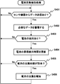
- FIG. 7 is a flowchart for explaining the battery replacement notification process in the server device 40.
- the power supply device 20 generates electric power using energy generated in the freezing warehouse RW (step S101).
- the power generation unit 22 converts the rotational energy of the windmill 21 into electric energy and generates power.
- Step S101 corresponds to the energy harvesting step in the claims of the present invention.
- the power supply device 20 supplies the electric power generated in step S101 to the sensor device 30 (step S102). That is, the power supply unit 23 supplies the electric current generated by the power generation unit 22 to the power supply side coil to generate a magnetic field, and supplies electric power to the sensor device 30 by electromagnetic induction. Note that power may be supplied to the sensor device 30 by magnetic field resonance instead of electromagnetic induction. In addition, the power supply unit 23 may radiate microwaves or ultrasonic waves to supply power to the sensor device 30. Step S102 corresponds to a power supply step in the claims of the present invention.
- the power supply device 20 returns the process to step S101 described above.
- One sensor device 30 receives the power supplied in step S102 (step S201).
- the power receiving unit 31 receives power by electromagnetic induction due to a magnetic field generated in the power supply unit 23 of the power supply device 20. Note that power may be received by magnetic field resonance.
- the power receiving unit 31 may convert microwaves or ultrasonic waves radiated from the power supply unit 23 into electric power and receive electric power.
- Step S201 corresponds to the power receiving step in the claims of the present invention.
- Step S202 corresponds to the power storage step in the claims of the present invention.
- the sensor device 30 operates by consuming the power stored in the power storage unit 32 (step S203).
- Step S203 corresponds to an operation step in the claims of the present invention.
- the power supply of battery 39 is switched in the power supply switching process described below.
- the sensor device 30 operates by consuming the power of the battery 39.
- the sensor device 30 returns the process to step S201 described above.
- the power supply device 20 generates electric power using energy generated in the freezing warehouse RW, and supplies the generated electric power to the sensor device 30.
- the sensor device 30 receives the power supplied from the power supply device 20, stores the received power in the power storage unit 32, and operates by consuming the power stored in the power storage unit 32. .
- the electric power generated by the energy harvesting can be supplied to the sensor device 30.
- the sensor device 30 compares the voltage of the power storage unit 32 with the voltage of the battery 39 (Step S301).
- the voltage detection unit 33 compares the voltage of the power storage unit 32 and the voltage of the battery 39 with the comparator 331 illustrated in FIG.
- the sensor device 30 determines whether or not the voltage of the power storage unit 32 is higher (step S302). For example, it is determined whether the comparator 331 shown in FIG. 3 has output a negative power supply switching signal.
- the sensor device 30 determines that the voltage of the power storage unit 32 is higher (step S302; Yes)
- the sensor device 30 switches the power supply to the power storage unit 32 (step S103).
- the comparator 331 shown in FIG. 3 outputs a negative power supply switching signal
- the switch 34 is connected to the power storage unit 32 side, and supplies the power of the power storage unit 32 to the controller 35. Then, the sensor device 30 returns the process to step S301 described above.
- Step S302 if it is determined that the voltage of the battery 39 is higher (including the case where both voltages are equal) (Step S302; No), the sensor device 30 switches the power supply to the battery 39 (Step S304). For example, when the comparator 331 shown in FIG. 3 outputs a positive power supply switching signal, the switch 34 is connected to the battery 39 and supplies the power of the battery 39 to the controller 35. Then, the sensor device 30 returns the process to step S301 described above.
- the voltage of the power storage unit 32 is higher than the voltage of the battery 39.
- the sensor device 30 controls the power storage unit 32 as a power supply. Note that, for example, when the refrigerator main body performs the defrosting operation and the cold air is temporarily not output from the cold air duct 10 (or the output cold air is extremely weakened), the power is supplied from the power supply device 20. The power stored in the power storage unit 32 is consumed without being supplied.
- the switch 34 is switched to the battery 39 side, and the sensor device 30 operates using the battery 39 as a power supply.
- the switch 34 is eventually switched to the power storage unit 32 side, and the sensor device 30 operates using the power storage unit 32 as a power supply.
- the sensor device 30 can be operated without using the battery 39 in the sensor device 30 (without consuming the power of the battery 39). Therefore, in the sensor device 30, the power consumption can be reduced more strongly, the replacement time of the battery 39 is delayed, and the maintenance is facilitated.
- the server device 40 determines whether or not data has been transmitted from the sensor device 30 (step S401). That is, the control unit 43 determines whether the communication unit 41 has received data transmitted from the sensor device 30.
- step S401 determines that there is no data transmission from the sensor device 30 (step S401; No)
- the server device 40 repeats the process of step S401.
- the server device 40 accumulates necessary data (step S402). That is, the control unit 43 collects necessary data from the received data and stores the data in the data storage unit 42. The control unit 43 collects at least one of the temperature, the humidity, and the power supply switching signal (data associated with the date and time), and causes the data storage unit 42 to store the data.
- the server device 40 determines whether the battery 39 has been used (step S403). For example, the control unit 43 determines whether or not the data stored in step S402 includes a power supply switching signal (positive power supply switching signal).
- step S403 If the server device 40 determines that the battery 39 has not been used (step S403; No), the server device 40 returns the process to step S401 described above.
- the server device 40 updates the accumulated use time of the battery 39 (step S404). That is, the control unit 43 totals the power supply switching signal and the data of the date and time associated therewith, and updates the accumulated use time of the battery 39. For example, when the power switching signal accumulated in time series changes from a negative power switching signal to a positive power switching signal, the management unit 432 stores the date and time associated with the positive power switching signal. Then, the management unit 432 searches for data that changes to the negative power supply switching signal, and updates the cumulative use time by adding the time from the stored date and time to the date and time associated with the negative power supply switching signal. When data that changes to the negative power supply switching signal has not been accumulated, the management unit 432 adds the time from the stored date and time to the current date and time to update the accumulated use time.
- the server device 40 determines whether the time to replace the battery 39 has come (step S405). For example, when the cumulative use time updated in step S204 exceeds the specified time set for replacement, the control unit 43 determines that the time to replace the battery 39 has come.
- step S405 the server device 40 determines that the time to replace the battery 39 has not come (step S405; No). If the server device 40 determines that the time to replace the battery 39 has not come (step S405; No), the server device 40 returns the process to step S401 described above.
- step S405 when it is determined that the time to replace the battery 39 has come (step S405; Yes), the server device 40 notifies the user of the replacement of the battery 39 (step S406). That is, the control unit 43 controls the communication unit 41 to transmit a message prompting battery replacement to, for example, a terminal of the administrator. Then, the server device 40 returns the process to step S204 described above.
- the use status of the battery 39 in the sensor device 30 can be grasped, and the replacement of the battery 39 can be appropriately encouraged when the replacement time of the battery 39 has come.
- a configuration in which the sensor device 30 measures the voltage value of the battery 39 becomes unnecessary, and the configuration of the sensor device 30 can be simplified. .
- the server device 40 since the power supply switching signal and the data of the date and time associated with the power supply switching signal are stored, the accumulated use time of the battery 39 can be accurately managed, and the time to replace the battery 39 is properly notified. be able to.
- a special environment such as a freezing warehouse RW
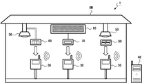
- the power supply device 60 may generate power using a temperature difference generated in the lighting device 50, or may generate power using the vibration generated in the cold air duct 10.
- the power supply device 80 may generate power using the light of the lighting device 50.
- FIG. 9 is a block diagram illustrating an example of a configuration of the power supply device 60 and the sensor device 30.
- the power supply device 60 includes the temperature difference power generation unit 61 and the power supply unit 23.
- the temperature difference power generation unit 61 is, for example, a Seebeck element, and is attached to an element such as a driver element in the lighting device 50 that generates heat during operation (when the lighting device 50 is turned on).
- the temperature difference power generation unit 61 generates a potential difference due to the Seebeck effect and generates power when a temperature difference occurs between the element that generates heat and the surroundings.
- the power supply unit 23 is the same as the power supply unit 23 in FIG. 2 described above. That is, the power supply unit 23 includes, for example, a power supply side coil, causes the current generated by the temperature difference power generation unit 61 to flow through the power supply side coil to generate a magnetic field, and supplies electric power to the sensor device 30 (power reception unit 31) by electromagnetic induction. Supply. Further, instead of electromagnetic induction, electric power may be supplied to the sensor device 30 by magnetic field resonance. In addition, the power supply unit 23 may radiate microwaves or ultrasonic waves to supply power to the sensor device 30.
- FIG. 10 is a block diagram illustrating an example of a configuration of the power supply device 70 and the sensor device 30.
- the power supply device 70 includes the vibration power generation unit 71 and the power supply unit 23.
- the vibration power generation unit 71 is, for example, a piezoelectric element, and is attached to the cold air duct 10.
- the vibration power generation unit 71 converts vibration energy into electric power by the piezoelectric effect and generates electric power.
- the power supply unit 23 is the same as the power supply unit 23 in FIG. 2 described above.
- the power supply unit 23 includes, for example, a power supply side coil, causes the current generated by the vibration power generation unit 71 to flow through the power supply side coil to generate a magnetic field, and supplies electric power to the sensor device 30 (power reception unit 31) by electromagnetic induction. Supply. Further, instead of electromagnetic induction, electric power may be supplied to the sensor device 30 by magnetic field resonance.
- the power supply unit 23 may radiate microwaves or ultrasonic waves to supply power to the sensor device 30.
- FIG. 11 is a block diagram illustrating an example of a configuration of the power supply device 80 and the sensor device 30.
- the power supply device 80 includes a PV power generation unit 81 and the power supply unit 23.
- the PV power generation unit 81 is, for example, a solar cell, and is attached to face the light source of the lighting device 50.
- the PV power generation unit 81 generates light by converting light energy into electric power by the photovoltaic effect.
- the power supply unit 23 is the same as the power supply unit 23 in FIG. 2 described above. That is, the power supply unit 23 includes, for example, a power supply side coil, causes the current generated by the PV power generation unit 81 to flow through the power supply side coil to generate a magnetic field, and supplies electric power to the sensor device 30 (power reception unit 31) by electromagnetic induction. Supply. Further, instead of electromagnetic induction, electric power may be supplied to the sensor device 30 by magnetic field resonance. In addition, the power supply unit 23 may radiate microwaves or ultrasonic waves to supply power to the sensor device 30.
- a plurality of power supply devices among these power supply devices 20 and 60 to 80 may be combined to supply power to one sensor device 30.
- the power supply device 20 and the power supply device 60 may correspond to the sensor device 30, and power may be supplied from at least one of the power supply devices 20 and 60.
- the sensor device 30 may include two power receiving units 31 so that power can be individually supplied to each of the power supply devices 20 and 60.
- the present invention is applied to the freezing warehouse RW has been described as an example. Is applicable.
- the present invention can be similarly applied to a computer room where a mainframe or various server devices are arranged, or an artificial light type plant factory where plants typified by vegetables are grown indoors. it can.
- the present invention can be suitably applied to a management system, a sensor device, and a power supply method capable of supplying electric power generated by energy harvesting to a sensor device.
Landscapes
- Engineering & Computer Science (AREA)
- Chemical & Material Sciences (AREA)
- Combustion & Propulsion (AREA)
- Physics & Mathematics (AREA)
- Mechanical Engineering (AREA)
- Thermal Sciences (AREA)
- General Engineering & Computer Science (AREA)
- Power Engineering (AREA)
- Charge And Discharge Circuits For Batteries Or The Like (AREA)
Abstract
給電装置(20)及びセンサ機器(30)は、冷凍倉庫内に設置されている。給電装置(20)において、発電部(22)は、凍倉庫内に生じる風力エネルギーを用いて電力を発電する。また、給電部(23)は、発電部(22)が発電した電力をセンサ機器(30)に供給する。センサ機器(30)において、受電部(31)は、給電装置(20)から給電された電力を受信する。蓄電部(32)は、受電部(31)が受電した電力を蓄積する。コントローラ(35)は、蓄電部(32)に蓄積された電力を消費して動作する。
Description
本発明は、管理システム、センサ機器、及び、給電方法に関する。
近年、IoT(Internet of Things)機器が広く用いられ、収集された種々のデータが活用されている。例えば、冷凍倉庫内には、IoT機器としてセンサ機器が配置され、そのセンサ機器にて検出したデータ(温度、湿度等)が、サーバ装置に適宜送られるようになっている。通常、センサ機器は、電池(一例として、乾電池のような一次電池)が内蔵され、それを電源として動作する場合が多い。特に、冷凍倉庫内のように、外部からセンサ機器への電力供給が困難な場所に設置される場合には、電池を内蔵することが必須となる。
また、最近では、光、風力、振動、温度差等のエネルギーを利用して発電する環境発電にも注目が集まっている。このような環境発電の技術をセンサ機器に適用して、低消費電力化を図り、電池の消耗を減らしたり、或いは、電池を内蔵せずにセンサ機器を動作させることも研究されている。
例えば、特許文献1には、温度差による発電を利用した電子機器の発明が開示されている。この電子機器は、熱電変換素子を備えており、発熱したCPU(Central Processing Unit)と周囲との温度差により発電する。そして、発電した電力は、バッテリ(二次電池)に蓄電され、電子機器がその電力を消費できるようになっている。このような特許文献1の発明を、上述したセンサ機器に適用することも考えられる。
しかしながら、電池で動作するセンサ機器には、低消費電力版の素子(一例として、マイコン素子)が用いられており、動作時の発熱が低く抑えられている。そのため、センサ機器の素子と周囲との間に十分な温度差が生じず、温度差による発電を利用することができなかった。
そのため、例えば、冷凍倉庫内に生じるエネルギーを用いて環境発電し、発電した電力をセンサ機器に給電するといった新たな技術の開発が求められていた。
本発明は、上述のような課題を解決するためになされたものであり、環境発電した電力をセンサ機器に給電することのできる管理システム、センサ機器、及び、給電方法を提供することを目的とする。
上記目的を達成するため、本発明に係る管理システムは、
冷凍倉庫における管理システムであって、
給電装置及びセンサ機器が、前記冷凍倉庫内に設置されており、
前記給電装置は、
前記冷凍倉庫内に生じるエネルギーを用いて電力を発電する環境発電手段と、
前記環境発電手段が発電した電力を前記センサ機器に給電する給電手段と、を備え、
前記センサ機器は、
前記給電装置から給電された電力を受電する受電手段と、
前記受電手段が受電した電力を蓄積する蓄電手段と、
前記蓄電手段に蓄積された電力を消費して動作する制御手段と、を備える。
冷凍倉庫における管理システムであって、
給電装置及びセンサ機器が、前記冷凍倉庫内に設置されており、
前記給電装置は、
前記冷凍倉庫内に生じるエネルギーを用いて電力を発電する環境発電手段と、
前記環境発電手段が発電した電力を前記センサ機器に給電する給電手段と、を備え、
前記センサ機器は、
前記給電装置から給電された電力を受電する受電手段と、
前記受電手段が受電した電力を蓄積する蓄電手段と、
前記蓄電手段に蓄積された電力を消費して動作する制御手段と、を備える。
この発明によれば、給電装置において、環境発電手段は冷凍倉庫内に生じるエネルギーを用いて電力を発電し、給電手段は発電された電力をセンサ機器に給電する。一方、センサ機器において、受電手段は給電装置から給電された電力を受電し、蓄電手段は受電した電力を蓄積し、そして、制御手段は蓄積された電力を消費して動作する。この結果、環境発電した電力をセンサ機器に給電することができる。
以下、本発明の実施形態について、図面を参照しながら詳細に説明する。なお、図中同一または相当部分には同一符号を付す。以下では、冷凍倉庫における管理システムを一例として説明するが、後述するように、例えば、温度及び湿度が一定に管理される管理システムにおいても同様に本発明を適用することができる。すなわち、以下に説明する実施形態は説明のためのものであり、本発明の範囲を制限するものではない。従って、当業者であればこれらの各要素または全要素をこれと均等なものに置換した実施形態を採用することが可能であるが、これらの実施形態も本発明の範囲に含まれる。
(実施形態1)
図1は、本発明の実施形態1に係る管理システム1の全体構成の一例を示す図である。この管理システム1は、一例として、冷凍倉庫RWにおいて温度及び湿度を一定に管理するシステムである。
図1は、本発明の実施形態1に係る管理システム1の全体構成の一例を示す図である。この管理システム1は、一例として、冷凍倉庫RWにおいて温度及び湿度を一定に管理するシステムである。
図示するように、管理システム1は、冷凍倉庫RW内に配置された冷風ダクト10、給電装置20、及び、センサ機器30と、冷凍倉庫RW外に配置されたサーバ装置40とを備えている。なお、図1では、給電装置20とセンサ機器30とが、1組だけ示されているが、複数組の給電装置20及びセンサ機器30が、冷凍倉庫RW内に配置されていてもよい。また、以下では、給電装置20とセンサ機器30とが、1対1に対応している場合について説明するが、後述するように、給電装置20とセンサ機器30との対応が、1対1以外であってもよい。
冷風ダクト10は、図示せぬ冷凍機本体にて生成された冷気を、冷凍倉庫RW内に出力する。例えば、冷凍機本体は、室内(冷凍倉庫RW内)空気と冷媒とを熱交換する室内熱交換器と、圧縮機と、外気と冷媒とを熱交換する室外熱交換器と、膨張弁とを備えている。そして、冷凍機本体は、冷媒を、圧縮機→室外熱交換器→膨張弁→室内熱交換器→圧縮機・・・の順に循環させ、冷凍サイクルを構成する。冷凍機本体は、室内熱交換器にて冷却された空気(冷気)を、例えば、ファンを回転させて冷風ダクト10まで導き、冷凍倉庫RW内に出力する。
給電装置20は、冷風ダクト10の近傍に配置され、冷風ダクト10から出力される冷気の風力エネルギーを利用して発電し、発電した電力をセンサ機器30に給電する。
センサ機器30は、給電装置20から給電された電力を蓄積する蓄電部(後述する蓄電部32)、又は、内蔵する電池(後述する電池39)の何れかを電源として動作し、検出した温度、湿度等のデータをサーバ装置40に送信する。なお、図1では、センサ機器30からサーバ装置40にデータが直接送られるように示してしているが、実際には、ネットワーク(一例として、インターネット)を通じて、センサ機器30からサーバ装置40にデータが送られるようになっている。
サーバ装置40は、センサ機器30から送られたデータを受信して蓄積する。なお、センサ機器30から送られたデータには、後述するような電源切替信号が含まれており、センサ機器30が電池を使用した累積使用時間が集計できるようになっている。そのため、サーバ装置40は、後述するように、センサ機器30における電池の交換時期が到来すると、例えば、管理者(図示せぬ管理者の端末装置)に電池の交換を促すメッセージを報知する。
以下、図2を参照して、給電装置20とセンサ機器30とについて、詳細に説明する。図2は、給電装置20、及び、センサ機器30の構成の一例を示すブロック図である。
まず、給電装置20は、風車21と、発電部22と、給電部23とを備えている。
風車21は、冷風ダクト10から出力される冷風に対向するように配置されており、冷風を受けて回転する。
発電部22は、本願発明の請求の範囲における環境発電手段に対応しており、風車21の回転エネルギーを電気エネルギーに変換して発電する。例えば、発電部22は、風車21の回転を複数のギアを組み合わせた増速器に伝え、この増速器からの回転駆動力によってロータの磁極を回転させ、電磁誘導により発電する。
給電部23は、本願発明の請求の範囲における給電手段に対応しており、例えば、給電側コイルを備え、発電部22により発電された電流を給電側コイルに流して磁界を発生させ、電磁誘導によりセンサ機器30(後述する受電部31)に電力を供給する。なお、電磁誘導の代わりに、磁界共振(磁界共鳴)によって、センサ機器30に電力を供給するようにしてもよい。
この他にも、給電部23は、マイクロ波又は超音波を放射して、センサ機器30に電力を供給してもよい。例えば、給電部23は、アンテナ素子を多数配列したアレーアンテナからマイクロ波を放射して、センサ機器30に電力を供給する。これら、マイクロ波又は超音波を用いる場合では、給電装置20(給電部23)とセンサ機器30(受電部31)とを、数ミリm程度まで近接させることなく、ある程度までの距離(一例として、数m)を隔てても、給電が可能となる。
続いて、センサ機器30は、受電部31と、蓄電部32と、電圧検知部33と、スイッチ34と、コントローラ35と、温度センサ36と、湿度センサ37と、無線送信部38と、電池39とを備えている。
受電部31は、本願発明の請求の範囲における受電手段に対応しており、例えば、受電側コイルを備え、給電装置20の給電部23に発生された磁界による電磁誘導によって受電する。なお、磁界共振によって受電してもよい。
この他にも、受電部31は、給電部23から放射されたマイクロ波又は超音波を電力に変換して受電してもよい。例えば、受電部31は、放射されたマイクロ波をアレーアンテナによって受信し、電圧降下の少ないダイオードを多数配列したダイオードアレイで整流して電力を得る。
蓄電部32は、本願発明の請求の範囲における蓄電手段に対応しており、例えば、二次電池、電気二重層コンデンサ等であり、受電部31が受電した電力を蓄える。
電圧検知部33は、本願発明の請求の範囲における電圧検知手段に対応しており、蓄電部32の電圧と、電池39の電圧とを検知する。電圧検知部33は、検知した電圧の高い方を示す電源切替信号を生成して、スイッチ34及びコントローラ35に供給する。また、電圧検知部33は、検知した両電圧のどちらも基準電圧を下回っている場合に、リセット信号を生成して、コントローラ35に供給する。
より具体的に、電圧検知部33は、図3に示すような回路によって構成されている。図3に示すように、コンパレータ331は、非反転入力が電池39に接続され、反転入力が蓄電部32に接続され、そして、出力がスイッチ34及びコントローラ35に接続されている。つまり、コンパレータ331は、電池39の電圧と、蓄電部32の電圧とを比較して、電源切替信号を出力する。例えば、コンパレータ331は、電池39の電圧の方が高かった場合に、正の電源切替信号を出力し、逆に、蓄電部32の電圧の方が高かった場合に、負の電源切替信号を出力する。
コンパレータ332は、非反転入力が電池39に接続され、反転入力が基準電圧回路335に接続され、そして、出力がOR回路334の一方の入力に接続されている。つまり、コンパレータ332は、電池39の電圧と、基準電圧回路335の電圧とを比較して、正又は負の信号を出力する。例えば、コンパレータ332は、電池39の電圧の方が高かった場合に、正の信号を出力し、逆に、基準電圧回路335の電圧の方が高かった場合(つまり、電池39の電圧が、基準電圧回路335の電圧を下回った場合)に、負の信号を出力する。
コンパレータ333は、非反転入力が蓄電部32に接続され、反転入力が基準電圧回路335に接続され、そして、出力がOR回路334の他方の入力に接続されている。つまり、コンパレータ333は、蓄電部32の電圧と、基準電圧回路335の電圧とを比較して、正又は負の信号を出力する。例えば、コンパレータ333は、蓄電部32の電圧の方が高かった場合に、正の信号を出力し、逆に、基準電圧回路335の電圧の方が高かった場合(つまり、蓄電部32の電圧が、基準電圧回路335の電圧を下回った場合)に、負の信号を出力する。
OR回路334は、図中において負論理で示されており、一方の入力がコンパレータ332の出力に接続され、他方の入力がコンパレータ333の出力に接続され、そして、出力がコントローラ35に接続されている。つまり、OR回路334は、コンパレータ332の出力及びコンパレータ333の出力がどちらも負の信号である場合にだけ、リセット信号(負の信号)をコントローラ35に出力する。一方、コンパレータ332の出力及びコンパレータ333の出力のうち、少なくとも一方が正の信号であれば、OR回路334は、正の信号を出力し、リセット信号とはならない。
基準電圧回路335は、例えば、リセット条件として定められた基準電圧を出力し、コンパレータ332の反転入力、及び、コンパレータ333の反転入力に供給する。
図2に戻って、スイッチ34は、コントローラ35の電源を、蓄電部32又は電池39の何れかに切り替えるスイッチ素子であり、電圧検知部33に制御される。例えば、上述した図3に示される回路の電圧検知部33の場合、正の電源切替信号(電池39の方が高電圧)がコンパレータ331から供給されると、スイッチ34は、電池39側に接続を切り替える。逆に、負の電源切替信号(蓄電部32の方が高電圧)がコンパレータ331から供給されると、スイッチ34は、蓄電部32側に接続を切り替える。つまり、電源切替信号は、スイッチ34の接続先を示す接続情報とも言える。
コントローラ35は、本願発明の請求の範囲における制御手段に対応しており、例えば、マイコン素子であり、センサ機器30全体を制御する。コントローラ35は、スイッチ34を介して、蓄電部32又は電池39の何れかに接続され、供給される電力によって以下のように動作する。
例えば、コントローラ35は、温度センサ36が検出した温度、及び、湿度センサ37が検出した湿度のデータを取得する。また、コントローラ35は、電圧検知部33から供給された電源切替信号(正又は負の電源切替信号)も取得する。なお、コントローラ35は、計時部(一例として、リアルタイムクロック)を備えており、温度、湿度、及び、電源切替信号を取得したそれぞれの日時(時刻だけでもよい)を対応付けておくものとする。そして、コントローラ35は、規定された送信タイミング(一例として、1時間毎)になると、無線送信部38を制御して、日時が対応付けられた、これら温度、湿度、及び、電源切替信号のデータを、サーバ装置40に送信する。
温度センサ36は、冷凍倉庫RW内(センサ機器30の近傍)の温度を検出する。
湿度センサ37は、冷凍倉庫RW内(センサ機器30の近傍)の湿度を検出する。
無線送信部38は、例えば、Wi-Fi(登録商標)若しくはBluetooth(登録商標)に代表される無線規格に沿って通信を行う。つまり、無線送信部38は、コントローラ35に制御され、温度、湿度、及び、電源切替信号を含むデータを、サーバ装置40に送信する。なお、上述したように、電源切替信号は、スイッチ34の接続先を示す接続情報とも言える。
電池39は、乾電池に代表される一次電池であり、スイッチ34を介して、コントローラ35に電力を供給する。なお、電池39は、例えば、センサ機器30内に設けられたケースに装着して保持されるようになっており、消耗した際に、交換可能となっている。
以下、図4を参照して、サーバ装置40について、詳細に説明する。図4は、サーバ装置40の構成の一例を示すブロック図である。
図示するように、サーバ装置40は、通信部41と、データ蓄積部42と、制御部43とを備えている。
通信部41は、センサ機器30から送られたデータを受信する。また、通信部41は、制御部43に制御され、例えば、センサ機器30における電池39の交換時期が到来すると、電池交換を促すメッセージを、例えば、管理者の端末装置に送信する。
データ蓄積部42は、通信部41が受信したデータを蓄積する。例えば、データ蓄積部42は、日時が対応付けられた温度、湿度、及び、電源切替信号のデータを蓄積する。なお、電源切替信号、及び、それに対応付けられた日時は、後述するように、センサ機器30における電池39の累積使用時間を求めるために使用される。
制御部43は、CPU(Central Processing Unit)及びメモリを備えている。なお、CPUがメモリに格納されたプログラムを実行することにより、以下に説明するデータ収集部431及び管理部432が実現される。
データ収集部431は、通信部41が受信したデータから必要なデータを収集し、データ蓄積部42に蓄積させる。データ収集部431は、少なくとも、温度、湿度、及び、電源切替信号の何れかのデータ(日時が対応付けられたデータ)を収集して、データ蓄積部42に蓄積させる。
管理部432は、データ蓄積部42に蓄積されたデータに基づいて、センサ機器30を管理する。例えば、管理部432は、データ蓄積部42に蓄積された電源切替信号、及び、それに対応付けられた日時のデータを集計し、センサ機器30における電池39の累積使用時間を求める。例えば、時系列に蓄積された電源切替信号において、負の電源切替信号から正の電源切替信号に変化すると、管理部432は、正の電源切替信号に対応付けられた日時を記憶しておく。そして、管理部432は、次に負の電源切替信号に変化するデータを探し、記憶した日時から負の電源切替信号に対応付けられた日時までの時間を累積使用時間に加算する。なお、負の電源切替信号に変化するデータが未蓄積である場合、管理部432は、記憶した日時から現在日時までの時間を累積使用時間に加算する。
そして、このようにして求めた累積使用時間から、電池39の交換時期が到来したと判別すると(一例として、累積使用時間が規定時間を超えると)、管理部432は、通信部41を制御して、電池交換を促すメッセージを、例えば、管理者の端末に送信する。
以下、このような構成の管理システム1の動作について、図5~7を参照して説明する。図5は、給電装置20における給電処理、及び、センサ機器30における受電処理を説明するためのフローチャートである。また、図6は、センサ機器30における電源切替処理を説明するためのフローチャートである。そして、図7は、サーバ装置40における電池交換報知処理を説明するためのフローチャートである。
まず、図5を参照して、給電装置20における給電処理、及び、センサ機器30における受電処理について説明する。これらの給電処理及び受電処理は、給電装置20及びセンサ機器30において、繰り返し実行される。
まず、給電装置20は、冷凍倉庫RW内に生じるエネルギーを用いて電力を発電する(ステップS101)。例えば、風車21が冷風ダクト10から出力される冷風を受けて回転している場合に、発電部22は、風車21の回転エネルギーを電気エネルギーに変換して発電する。なお、ステップS101は、本願発明の請求の範囲における環境発電ステップに対応している。
給電装置20は、上記のステップS101にて発電した電力を、センサ機器30に給電する(ステップS102)。すなわち、給電部23は、発電部22によって発電された電流を給電側コイルに流して磁界を発生させ、電磁誘導によりセンサ機器30に電力を供給する。なお、電磁誘導の代わりに、磁界共振によって、センサ機器30に電力を供給するようにしてもよい。この他にも、給電部23は、マイクロ波又は超音波を放射して、センサ機器30に電力を供給してもよい。なお、ステップS102は、本願発明の請求の範囲における給電ステップに対応している。
そして、給電装置20は、上述したステップS101に処理を戻す。
一方のセンサ機器30は、上記のステップS102にて給電された電力を受電する(ステップS201)。例えば、受電部31は、給電装置20の給電部23に発生された磁界による電磁誘導によって受電する。なお、磁界共振によって受電してもよい。この他にも、受電部31は、給電部23から放射されたマイクロ波又は超音波を電力に変換して受電してもよい。なお、ステップS201は、本願発明の請求の範囲における受電ステップに対応している。
センサ機器30は、上記のステップS201にて受電した電力を蓄電部32に蓄積する(ステップS202)。ステップS202は、本願発明の請求の範囲における蓄電ステップに対応している。
センサ機器30は、蓄電部32に蓄積された電力を消費して動作する(ステップS203)。ステップS203は、本願発明の請求の範囲における動作ステップに対応している。なお、蓄電部32に十分な電力が蓄積されておらず、蓄電部32の電圧よりも、電池39の電圧の方が高い場合には、以下に説明する電源切替処理にて電源が電池39の方に切り替えられているため、センサ機器30は、電池39の電力を消費して動作する。
そして、センサ機器30は、上述したステップS201に処理を戻す。
このような給電処理により、給電装置20は、冷凍倉庫RW内に生じるエネルギーを用いて電力を発電し、発電した電力をセンサ機器30に給電する。また、受電処理により、センサ機器30は、給電装置20から給電された電力を受電し、受電した電力を蓄電部32に蓄積し、そして、蓄電部32に蓄積された電力を消費して動作する。この結果、環境発電した電力をセンサ機器30に給電することができる。
次に、図6を参照して、センサ機器30における電源切替処理について説明する。この電源切替処理は、例えば、センサ機器30において、他の処理と並行して、繰り返し実行される。
まず、センサ機器30は、蓄電部32の電圧と電池39の電圧とを比較する(ステップS301)。例えば、電圧検知部33は、図3に示すコンパレータ331によって、蓄電部32の電圧と電池39の電圧とを比較する。
センサ機器30は、蓄電部32の電圧の方が大きいか否かを判別する(ステップS302)。例えば、図3に示すコンパレータ331が、負の電源切替信号を出力したかどうかを判別する。
センサ機器30は、蓄電部32の電圧の方が大きいと判別すると(ステップS302;Yes)、電源を蓄電部32に切り替える(ステップS103)。例えば、図3に示すコンパレータ331が負の電源切替信号を出力した場合に、スイッチ34は、蓄電部32側に接続し、蓄電部32の電力をコントローラ35に供給する。そして、センサ機器30は、上述したステップS301に処理を戻す。
一方、電池39の電圧の方が大きい(両電圧が等しい場合も含む)と判別した場合(ステップS302;No)に、センサ機器30は、電源を電池39に切り替える(ステップS304)。例えば、図3に示すコンパレータ331が正の電源切替信号を出力した場合に、スイッチ34は、電池39側に接続し、電池39の電力をコントローラ35に供給する。そして、センサ機器30は、上述したステップS301に処理を戻す。
このような電源切替処理によって、給電装置20から電力が供給され、蓄電部32に電力が蓄電されている間は、蓄電部32の電圧が電池39の電圧よりも高くなるため、スイッチ34が蓄電部32側に切り替わり、蓄電部32を電源としてセンサ機器30(コントローラ35)が動作することになる。なお、例えば、冷凍機本体が除霜運転を行い、冷風ダクト10から一時的に冷風が出力されなくなる(若しくは、出力される冷風が極端に弱まる)といった状況が生じると、給電装置20から電力が供給されずに蓄電部32に蓄えられた電力が消費されていく。この場合、やがて、電池39の電圧が蓄電部32の電圧よりも高くなるため、スイッチ34が電池39側に切り替わり、電池39を電源としてセンサ機器30が動作することになる。その後、冷風ダクト10から冷風の出力が再開される(若しくは、出力される冷風が強まる)と、給電装置20からの給電も再開され、蓄電部32に蓄電されていく。この場合、やがて、スイッチ34が蓄電部32側に切り替わり、蓄電部32を電源としてセンサ機器30が動作することになる。
このように、冷凍倉庫RWに生じる風力エネルギーを用いて環境発電(風力発電)し、発電した電力をセンサ機器30に給電することができる。そして、このような給電により、センサ機器30における電池39を使用せずに(電池39の電力を消費せずに)、センサ機器30を動作させることができる。そのため、センサ機器30にて、より強力に低消費電力化を図ることができ、電池39の交換時期を遅らせ、メンテナンスも容易となる。
次に、図7を参照して、サーバ装置40における電池交換報知処理について説明する。この電池交換報知処理は、例えば、サーバ装置40において、他の処理と並行して繰り返し実行される。
まず、サーバ装置40は、センサ機器30からデータ送信があったか否かを判別する(ステップS401)。すなわち、制御部43は、通信部41が、センサ機器30から送られたデータを受信したかどうかを判別する。
サーバ装置40は、センサ機器30からデータ送信がなかったと判別すると(ステップS401;No)、当該ステップS401の処理を繰り返す。
一方、センサ機器30からデータ送信があったと判別した場合(ステップS401;Yes)に、サーバ装置40は、必要なデータを蓄積する(ステップS402)。すなわち、制御部43は、受信したデータから必要なデータを収集し、データ蓄積部42に蓄積させる。制御部43は、少なくとも、温度、湿度、及び、電源切替信号の何れかのデータ(日時が対応付けられたデータ)を収集して、データ蓄積部42に蓄積させる。
サーバ装置40は、電池39の使用があったか否かを判別する(ステップS403)。例えば、制御部43は、ステップS402にて蓄積したデータに、電源切替信号(正の電源切替信号)が含まれていたかどうかを判別する。
サーバ装置40は、電池39の使用がなかったと判別すると(ステップS403;No)、上述したステップS401に処理を戻す。
一方、電池39の使用があったと判別した場合(ステップS403;Yes)に、サーバ装置40は、電池39の累積使用時間を更新する(ステップS404)。すなわち、制御部43は、電源切替信号、及び、それに対応付けられた日時のデータを集計し、電池39の累積使用時間を更新する。例えば、時系列に蓄積された電源切替信号において、負の電源切替信号から正の電源切替信号に変化すると、管理部432は、正の電源切替信号に対応付けられた日時を記憶しておく。そして、管理部432は、次に負の電源切替信号に変化するデータを探し、記憶した日時から負の電源切替信号に対応付けられた日時までの時間を累積使用時間に加算して更新する。なお、負の電源切替信号に変化するデータが未蓄積である場合、管理部432は、記憶した日時から現在日時までの時間を累積使用時間に加算して更新する。
サーバ装置40は、電池39の交換時期が到来したか否かを判別する(ステップS405)。例えば、制御部43は、ステップS204にて更新した累積使用時間が、交換のために定められた規定時間を超えると、電池39の交換時期が到来したと判別する。
サーバ装置40は、電池39の交換時期が到来していないと判別すると(ステップS405;No)、上述したステップS401に処理を戻す。
一方、電池39の交換時期が到来したと判別した場合(ステップS405;Yes)に、サーバ装置40は、電池39の交換を報知する(ステップS406)。すなわち、制御部43は、通信部41を制御して、電池交換を促すメッセージを、例えば、管理者の端末に送信する。そして、サーバ装置40は、上述したステップS204に処理を戻す。
このような電池交換報知処理によって、センサ機器30における電池39の使用状況をに把握し、電池39の交換時期が到来した際に、電池39の交換を適切に促すことができる。特に、電池39の使用状況をサーバ装置40側で管理することにより、センサ機器30にて電池39の電圧値を計測するような構成が不要となり、センサ機器30の構成を簡略化することができる。
また、電源切替信号、及び、それに対応付けられた日時のデータを蓄積しているため、電池39の累積使用時間を正確に管理することができ、電池39の交換時期の到来を適切に報知することができる。なお、冷凍倉庫RWという特殊環境下においては、低温状態を極力維持する必要があるため、電池39の交換作業の頻度を少なくするのが望ましく、また、その交換作業が突発的となるのを避けたい。そのため、例えば、冷凍倉庫RWにおいて、搬入作業若しくは搬出作業がスケジュールされている場合に、サーバ装置40は、スケジュールされた搬入作業若しくは搬出作業の日時を合わせて、電池39の交換を報知するようにしてもよい。
(他の実施形態)
上記の実施形態1では、環境発電の一例として、風力発電によって、給電装置20が発電する場合を一例として説明したが、他の種類の環境発電によって給電装置が発電を行うようにし、発電した電力をセンサ機器30に給電してもよい。
上記の実施形態1では、環境発電の一例として、風力発電によって、給電装置20が発電する場合を一例として説明したが、他の種類の環境発電によって給電装置が発電を行うようにし、発電した電力をセンサ機器30に給電してもよい。
例えば、図8に示すように、照明装置50に生じる温度差を利用して給電装置60が発電してもよく、また、冷風ダクト10に生じる振動を利用して給電装置70が発電してもよく、更に、照明装置50の光を利用して給電装置80が発電してもよい。
以下、図9~11を参照して、各種の環境発電によって発電する給電装置60~80について、詳細に説明する。なお、図9~11において、センサ機器30の構成は、上述した図2における構成と同じである。そのため、センサ機器30の説明は省略する。
まず、図9を参照して、照明装置50に生じる温度差を利用して温度差発電を行う給電装置60について説明する。図9は、給電装置60、及び、センサ機器30の構成の一例を示すブロック図である。
給電装置60は、温度差発電部61と、給電部23とを備えている。
温度差発電部61は、例えば、ゼーベック素子であり、照明装置50におけるドライバ素子のような動作時(照明装置50が点灯時)に発熱する素子に取り付けられている。温度差発電部61は、発熱した素子と周囲との温度差が生じると、ゼーベック効果により電位差が生じて発電する。
給電部23は、上述した図2の給電部23と同じである。つまり、給電部23は、例えば、給電側コイルを備え、温度差発電部61により発電された電流を給電側コイルに流して磁界を発生させ、電磁誘導によりセンサ機器30(受電部31)に電力を供給する。また、電磁誘導の代わりに、磁界共振によって、センサ機器30に電力を供給するようにしてもよい。この他にも、給電部23は、マイクロ波又は超音波を放射して、センサ機器30に電力を供給してもよい。
このような給電装置60を用いた場合でも、冷凍倉庫RWにて使用される照明装置50に生じる熱エネルギーを用いて環境発電(温度差発電)し、発電した電力をセンサ機器30に給電することができる。そして、このような給電により、センサ機器30における電池39を使用せずに(電池39の電力を消費せずに)、センサ機器30を動作させることができる。そのため、センサ機器30にて、より効果的に低消費電力化を図ることができ、電池39の交換時期を遅らせ、メンテナンスも容易となる。
続いて、図10を参照して、冷風ダクト10に生じる振動を利用して振動発電を行う給電装置70について説明する。図10は、給電装置70、及び、センサ機器30の構成の一例を示すブロック図である。
給電装置70は、振動発電部71と、給電部23とを備えている。
振動発電部71は、例えば、圧電素子であり、冷風ダクト10に取り付けられている。振動発電部71は、圧電効果により振動エネルギーを電力に変換して発電する。
給電部23は、上述した図2の給電部23と同じである。つまり、給電部23は、例えば、給電側コイルを備え、振動発電部71により発電された電流を給電側コイルに流して磁界を発生させ、電磁誘導によりセンサ機器30(受電部31)に電力を供給する。また、電磁誘導の代わりに、磁界共振によって、センサ機器30に電力を供給するようにしてもよい。この他にも、給電部23は、マイクロ波又は超音波を放射して、センサ機器30に電力を供給してもよい。
このような給電装置70を用いた場合でも、冷風ダクト10に生じる振動エネルギーを用いて環境発電(振動発電)し、発電した電力をセンサ機器30に給電することができる。そして、このような給電により、センサ機器30における電池39を使用せずに(電池39の電力を消費せずに)、センサ機器30を動作させることができる。そのため、センサ機器30にて、より効果的に低消費電力化を図ることができ、電池39の交換時期を遅らせ、メンテナンスも容易となる。
最後に、図11を参照して、照明装置50から照射される光を利用してPV(PhotoVoltaics)発電を行う給電装置80について説明する。図11は、給電装置80、及び、センサ機器30の構成の一例を示すブロック図である。
給電装置80は、PV発電部81と、給電部23とを備えている。
PV発電部81は、例えば、太陽電池であり、照明装置50の光源に対向するように取り付けられている。PV発電部81は、光起電力効果により、光エネルギーを電力に変換して発電する。
給電部23は、上述した図2の給電部23と同じである。つまり、給電部23は、例えば、給電側コイルを備え、PV発電部81により発電された電流を給電側コイルに流して磁界を発生させ、電磁誘導によりセンサ機器30(受電部31)に電力を供給する。また、電磁誘導の代わりに、磁界共振によって、センサ機器30に電力を供給するようにしてもよい。この他にも、給電部23は、マイクロ波又は超音波を放射して、センサ機器30に電力を供給してもよい。
このような給電装置80を用いた場合でも、照明装置50から照射される光エネルギーを用いて環境発電(PV発電)し、発電した電力をセンサ機器30に給電することができる。そして、このような給電により、センサ機器30における電池39を使用せずに(電池39の電力を消費せずに)、センサ機器30を動作させることができる。そのため、センサ機器30にて、より効果的に低消費電力化を図ることができ、電池39の交換時期を遅らせ、メンテナンスも容易となる。
また、これらの給電装置20,60~80のうち、複数の給電装置を組み合わせて、1つのセンサ機器30に、電力を供給するようにしてもよい。例えば、給電装置20及び給電装置60と、センサ機器30とを対応させて、給電装置20,60の少なくとも一方から電力が供給されるようにしてもよい。なお、センサ機器30は、受電部31を2つ備えるようにして、給電装置20,60毎に給電が個別に受けられるようにしてもよい。
上記の管理システム1では、給電装置20,60~80からセンサ機器30へ、ワイヤレス給電する場合について説明したが、給電装置20,60~80とセンサ機器30とを有線にて接続して、給電するようにしてもよい。この場合でも、給電装置20,60~80とセンサ機器30との間が閉じた系であるため、例えば、商用電源を供給する場合に比べ、とても容易である(つまり、供給用のコンセントを冷凍倉庫RW内に設置する手間が不要となるため)。
上記の管理システム1では、冷凍倉庫RWに適用される場合を一例として説明したが、冷凍倉庫RW以外の施設でも、温度及び湿度が一定に保たれるような施設であれば、同様に本発明を適用可能である。例えば、メインフレーム又は各種サーバ装置が配置されるようなコンピュータ室、若しくは、屋内で野菜に代表される植物が栽培される人工光型の植物工場などにおいても、本発明を同様に適用することができる。
本発明は、広義の精神と範囲を逸脱することなく、様々な実施形態及び変形が可能である。また、上述した実施形態は、本発明を説明するためのものであり、本発明の範囲を限定するものではない。つまり、本発明の範囲は、実施形態ではなく、請求の範囲によって示される。そして、請求の範囲内及びそれと同等の発明の意義の範囲内で施される様々な変形が、本発明の範囲内とみなされる。
本発明は、環境発電した電力をセンサ機器に給電することのできる管理システム、センサ機器、及び、給電方法に好適に採用され得る。
1 管理システム、10 冷風ダクト、20,60,70,80 給電装置、21 風車、22 発電部、 61 温度差発電部、71 振動発電部、81 PV発電部、23 給電部、30 センサ機器、31 受電部、32 蓄電部、33 電圧検知部、331,332,333 コンパレータ、334 OR回路、335 基準電圧回路、34 スイッチ、35、コントローラ、36、温度センサ、37 湿度センサ、38 無線送信部、39 電池、40 サーバ装置、41 通信部、42 データ蓄積部、43 制御部、431 データ収集部、432 管理部、50 照明装置
Claims (8)
- 冷凍倉庫における管理システムであって、
給電装置及びセンサ機器が、前記冷凍倉庫内に設置されており、
前記給電装置は、
前記冷凍倉庫内に生じるエネルギーを用いて電力を発電する環境発電手段と、
前記環境発電手段が発電した電力を前記センサ機器に給電する給電手段と、を備え、
前記センサ機器は、
前記給電装置から給電された電力を受電する受電手段と、
前記受電手段が受電した電力を蓄積する蓄電手段と、
前記蓄電手段に蓄積された電力を消費して動作する制御手段と、を備える、
管理システム。 - 前記環境発電手段は、前記冷凍倉庫内に生じる風力、温度差、振動、及び、光の何れかのエネルギーを用いて電力を発電する、
請求項1に記載の管理システム。 - 前記給電手段は、前記受電手段との間に電磁誘導又は磁界共振を生じさせることで、前記環境発電手段が発電した電力を、前記センサ機器に給電する、
請求項1に記載の管理システム。 - 前記給電手段は、前記受電手段に向けてマイクロ波又は超音波を放射することで、前記環境発電手段が発電した電力を、前記センサ機器に給電する、
請求項1に記載の管理システム。 - 前記センサ機器は、
前記制御手段に電力を供給可能な電池と、
前記制御手段との接続先を、前記電池又は前記蓄電手段の何れか一方に切り替えるスイッチと、
前記電池の電圧と前記蓄電手段の電圧とを比較して、電圧の高い方を検知する電圧検知手段と、を更に備え、
前記スイッチは、前記電圧検知手段が検知した方を、前記制御手段との接続先に切り替える、
請求項1に記載の管理システム。 - 前記センサ機器は、
前記スイッチの接続先を示す接続情報をサーバ装置に送信する送信部を更に備え、
前記サーバ装置は、
前記接続情報に基づいて、前記電池の累積使用時間を更新し、当該累積使用時間が基準時間を超えると、前記電池の交換を報知する、
請求項5に記載の管理システム。 - 冷凍倉庫内に配置されたセンサ機器であって、
前記冷凍倉庫内に生じるエネルギーを用いて電力を発電する給電装置から給電された電力を受電する受電手段と、
前記受電手段が受電した電力を蓄積する蓄電手段と、
前記蓄電手段に蓄積された電力を消費して動作する制御手段と、
を備えるセンサ機器。 - 冷凍倉庫にそれぞれ配置された給電装置からセンサ機器に給電する給電方法であって、
前記給電装置が、前記冷凍倉庫内に生じるエネルギーを用いて電力を発電する環境発電ステップと、
前記給電装置が、前記環境発電ステップにて発電した電力を前記センサ機器に給電する給電ステップと、
前記センサ機器が、前記給電ステップにて給電された電力を受電する受電ステップと、
前記センサ機器が、前記受電ステップにて受電した電力を蓄電部に蓄積する蓄電ステップと、
前記センサ機器が、前記蓄電部に蓄積された電力を消費して動作する動作ステップと、
を備える給電方法。
Priority Applications (2)
| Application Number | Priority Date | Filing Date | Title |
|---|---|---|---|
| JP2020531866A JPWO2020021624A1 (ja) | 2018-07-24 | 2018-07-24 | 管理システム、センサ機器、及び、給電方法 |
| PCT/JP2018/027658 WO2020021624A1 (ja) | 2018-07-24 | 2018-07-24 | 管理システム、センサ機器、及び、給電方法 |
Applications Claiming Priority (1)
| Application Number | Priority Date | Filing Date | Title |
|---|---|---|---|
| PCT/JP2018/027658 WO2020021624A1 (ja) | 2018-07-24 | 2018-07-24 | 管理システム、センサ機器、及び、給電方法 |
Publications (1)
| Publication Number | Publication Date |
|---|---|
| WO2020021624A1 true WO2020021624A1 (ja) | 2020-01-30 |
Family
ID=69182293
Family Applications (1)
| Application Number | Title | Priority Date | Filing Date |
|---|---|---|---|
| PCT/JP2018/027658 Ceased WO2020021624A1 (ja) | 2018-07-24 | 2018-07-24 | 管理システム、センサ機器、及び、給電方法 |
Country Status (2)
| Country | Link |
|---|---|
| JP (1) | JPWO2020021624A1 (ja) |
| WO (1) | WO2020021624A1 (ja) |
Cited By (2)
| Publication number | Priority date | Publication date | Assignee | Title |
|---|---|---|---|---|
| CN113659730A (zh) * | 2021-07-15 | 2021-11-16 | 哈尔滨工程大学 | 一种船用柴油机电控系统磁电式供电装置及供电方法 |
| JP2022181586A (ja) * | 2021-05-26 | 2022-12-08 | パナソニックIpマネジメント株式会社 | 貯蔵庫 |
Citations (6)
| Publication number | Priority date | Publication date | Assignee | Title |
|---|---|---|---|---|
| JPH06121463A (ja) * | 1992-10-02 | 1994-04-28 | Mitsubishi Heavy Ind Ltd | 輸送用冷凍ユニットの制御装置 |
| JPH0743065A (ja) * | 1993-07-28 | 1995-02-10 | Sanyo Electric Co Ltd | ショーケース |
| JP2006214644A (ja) * | 2005-01-07 | 2006-08-17 | Matsushita Electric Ind Co Ltd | 保存庫 |
| US7112893B1 (en) * | 2005-03-16 | 2006-09-26 | Villanueva Alvin P | Power generating wind turbine |
| KR100755143B1 (ko) * | 2006-06-02 | 2007-09-04 | 엘지전자 주식회사 | 식품 저장상태 감지용 센서에 무선으로 에너지를 공급하는냉장고 |
| WO2018029502A1 (en) * | 2016-08-11 | 2018-02-15 | Carrier Corporation | Energy harvesting system |
Family Cites Families (2)
| Publication number | Priority date | Publication date | Assignee | Title |
|---|---|---|---|---|
| US9711705B2 (en) * | 2010-11-16 | 2017-07-18 | Electron Holding Llc | Systems, methods and/or apparatus for thermoelectric energy generation |
| US20130324059A1 (en) * | 2012-06-01 | 2013-12-05 | Petari USA, Inc. | Wireless device with hybrid energy charging |
-
2018
- 2018-07-24 JP JP2020531866A patent/JPWO2020021624A1/ja active Pending
- 2018-07-24 WO PCT/JP2018/027658 patent/WO2020021624A1/ja not_active Ceased
Patent Citations (6)
| Publication number | Priority date | Publication date | Assignee | Title |
|---|---|---|---|---|
| JPH06121463A (ja) * | 1992-10-02 | 1994-04-28 | Mitsubishi Heavy Ind Ltd | 輸送用冷凍ユニットの制御装置 |
| JPH0743065A (ja) * | 1993-07-28 | 1995-02-10 | Sanyo Electric Co Ltd | ショーケース |
| JP2006214644A (ja) * | 2005-01-07 | 2006-08-17 | Matsushita Electric Ind Co Ltd | 保存庫 |
| US7112893B1 (en) * | 2005-03-16 | 2006-09-26 | Villanueva Alvin P | Power generating wind turbine |
| KR100755143B1 (ko) * | 2006-06-02 | 2007-09-04 | 엘지전자 주식회사 | 식품 저장상태 감지용 센서에 무선으로 에너지를 공급하는냉장고 |
| WO2018029502A1 (en) * | 2016-08-11 | 2018-02-15 | Carrier Corporation | Energy harvesting system |
Cited By (3)
| Publication number | Priority date | Publication date | Assignee | Title |
|---|---|---|---|---|
| JP2022181586A (ja) * | 2021-05-26 | 2022-12-08 | パナソニックIpマネジメント株式会社 | 貯蔵庫 |
| JP7668462B2 (ja) | 2021-05-26 | 2025-04-25 | パナソニックIpマネジメント株式会社 | 貯蔵庫 |
| CN113659730A (zh) * | 2021-07-15 | 2021-11-16 | 哈尔滨工程大学 | 一种船用柴油机电控系统磁电式供电装置及供电方法 |
Also Published As
| Publication number | Publication date |
|---|---|
| JPWO2020021624A1 (ja) | 2021-01-07 |
Similar Documents
| Publication | Publication Date | Title |
|---|---|---|
| Panatik et al. | Energy harvesting in wireless sensor networks: A survey | |
| US9031706B2 (en) | Air conditioner and method for controlling the same | |
| Alvarado et al. | Energy harvesting technologies for low‐power electronics | |
| US8791592B2 (en) | Air conditioner and method for controlling the same | |
| Cetinkaya et al. | Electric-field energy harvesting from lighting elements for battery-less internet of things | |
| CN102668302A (zh) | 运转计划方法、运转计划装置、热泵式热水供给系统的运转方法、以及热泵式热水供给供暖系统的运转方法 | |
| JP5816545B2 (ja) | 無線センサシステム | |
| Kaushik et al. | Experimental demonstration of multi-hop RF energy transfer | |
| US20200195056A1 (en) | Systems, methods, and apparatuses for energy distribution management | |
| US20210384565A1 (en) | Energy storage device temperature control method and apparatus | |
| US20110082601A1 (en) | Heating apparatus | |
| CN111448740A (zh) | 由具有集成开关模块的环境能源供电的无线建筑传感器 | |
| CN103743068A (zh) | 一种基于能效优化的中央空调冷却塔风机控制方法及系统 | |
| Abdal-Kadhim et al. | Application of thermal energy harvesting in powering WSN node with event-priority-driven dissemination algorithm for IoT applications | |
| WO2020021624A1 (ja) | 管理システム、センサ機器、及び、給電方法 | |
| Mohanty et al. | bSlight 2.0: Battery-free sustainable smart street light management system | |
| Abdul-Qawy | Energy-harvesting for IoT-based wireless nodes: a progress study | |
| CN114765383A (zh) | 基于温度的自调节冷却强化 | |
| Popa et al. | A classification of solutions for the energy limitation in wireless sensor networks | |
| Kaushal et al. | Solar energy harvesting in wireless sensor networks: A survey | |
| CN105243818A (zh) | 一种新型无线传感器网络节点 | |
| Routray et al. | Energy Harvesting Microcontrollers for IoT | |
| KR20220073944A (ko) | 자가 발전 무선 센서 | |
| Le | Global power management system for self-powered autonomous wireless sensor node | |
| Marsic et al. | Design and implementation of a wireless sensor communication system with low power consumption for energy harvesting technology |
Legal Events
| Date | Code | Title | Description |
|---|---|---|---|
| 121 | Ep: the epo has been informed by wipo that ep was designated in this application |
Ref document number: 18928042 Country of ref document: EP Kind code of ref document: A1 |
|
| ENP | Entry into the national phase |
Ref document number: 2020531866 Country of ref document: JP Kind code of ref document: A |
|
| NENP | Non-entry into the national phase |
Ref country code: DE |
|
| 122 | Ep: pct application non-entry in european phase |
Ref document number: 18928042 Country of ref document: EP Kind code of ref document: A1 |