WO2020008724A1 - 画像処理装置、画像処理方法及びプログラム - Google Patents
画像処理装置、画像処理方法及びプログラム Download PDFInfo
- Publication number
- WO2020008724A1 WO2020008724A1 PCT/JP2019/018616 JP2019018616W WO2020008724A1 WO 2020008724 A1 WO2020008724 A1 WO 2020008724A1 JP 2019018616 W JP2019018616 W JP 2019018616W WO 2020008724 A1 WO2020008724 A1 WO 2020008724A1
- Authority
- WO
- WIPO (PCT)
- Prior art keywords
- motion
- motion compensation
- mode
- image
- unit
- Prior art date
Links
Images


Classifications
-
- H—ELECTRICITY
- H04—ELECTRIC COMMUNICATION TECHNIQUE
- H04N—PICTORIAL COMMUNICATION, e.g. TELEVISION
- H04N19/00—Methods or arrangements for coding, decoding, compressing or decompressing digital video signals
- H04N19/10—Methods or arrangements for coding, decoding, compressing or decompressing digital video signals using adaptive coding
- H04N19/134—Methods or arrangements for coding, decoding, compressing or decompressing digital video signals using adaptive coding characterised by the element, parameter or criterion affecting or controlling the adaptive coding
- H04N19/136—Incoming video signal characteristics or properties
- H04N19/137—Motion inside a coding unit, e.g. average field, frame or block difference
- H04N19/139—Analysis of motion vectors, e.g. their magnitude, direction, variance or reliability
-
- H—ELECTRICITY
- H04—ELECTRIC COMMUNICATION TECHNIQUE
- H04N—PICTORIAL COMMUNICATION, e.g. TELEVISION
- H04N19/00—Methods or arrangements for coding, decoding, compressing or decompressing digital video signals
- H04N19/10—Methods or arrangements for coding, decoding, compressing or decompressing digital video signals using adaptive coding
- H04N19/102—Methods or arrangements for coding, decoding, compressing or decompressing digital video signals using adaptive coding characterised by the element, parameter or selection affected or controlled by the adaptive coding
- H04N19/103—Selection of coding mode or of prediction mode
- H04N19/109—Selection of coding mode or of prediction mode among a plurality of temporal predictive coding modes
-
- H—ELECTRICITY
- H04—ELECTRIC COMMUNICATION TECHNIQUE
- H04N—PICTORIAL COMMUNICATION, e.g. TELEVISION
- H04N19/00—Methods or arrangements for coding, decoding, compressing or decompressing digital video signals
- H04N19/10—Methods or arrangements for coding, decoding, compressing or decompressing digital video signals using adaptive coding
- H04N19/102—Methods or arrangements for coding, decoding, compressing or decompressing digital video signals using adaptive coding characterised by the element, parameter or selection affected or controlled by the adaptive coding
- H04N19/124—Quantisation
-
- H—ELECTRICITY
- H04—ELECTRIC COMMUNICATION TECHNIQUE
- H04N—PICTORIAL COMMUNICATION, e.g. TELEVISION
- H04N19/00—Methods or arrangements for coding, decoding, compressing or decompressing digital video signals
- H04N19/10—Methods or arrangements for coding, decoding, compressing or decompressing digital video signals using adaptive coding
- H04N19/169—Methods or arrangements for coding, decoding, compressing or decompressing digital video signals using adaptive coding characterised by the coding unit, i.e. the structural portion or semantic portion of the video signal being the object or the subject of the adaptive coding
- H04N19/17—Methods or arrangements for coding, decoding, compressing or decompressing digital video signals using adaptive coding characterised by the coding unit, i.e. the structural portion or semantic portion of the video signal being the object or the subject of the adaptive coding the unit being an image region, e.g. an object
- H04N19/176—Methods or arrangements for coding, decoding, compressing or decompressing digital video signals using adaptive coding characterised by the coding unit, i.e. the structural portion or semantic portion of the video signal being the object or the subject of the adaptive coding the unit being an image region, e.g. an object the region being a block, e.g. a macroblock
-
- H—ELECTRICITY
- H04—ELECTRIC COMMUNICATION TECHNIQUE
- H04N—PICTORIAL COMMUNICATION, e.g. TELEVISION
- H04N19/00—Methods or arrangements for coding, decoding, compressing or decompressing digital video signals
- H04N19/50—Methods or arrangements for coding, decoding, compressing or decompressing digital video signals using predictive coding
- H04N19/503—Methods or arrangements for coding, decoding, compressing or decompressing digital video signals using predictive coding involving temporal prediction
- H04N19/51—Motion estimation or motion compensation
- H04N19/537—Motion estimation other than block-based
- H04N19/54—Motion estimation other than block-based using feature points or meshes
Definitions
- the present disclosure relates to an image processing device, an image processing method, and a program, and particularly to an image processing device, an image processing method, and a program that can perform motion compensation at high speed and improve image coding efficiency.
- JVET Joint Video Exploration Team
- ITU-T International Telecommunication Union Telecommunication Standardization Sector
- An affine transformation of a reference image is performed based on motion vectors of two vertices in the reference image.
- An inter prediction process (Affine ⁇ motion ⁇ compensation (MC) ⁇ prediction) that performs motion compensation according to the following has been proposed (for example, see Non-Patent Documents 1 and 2).
- MC Motion ⁇ compensation
- a high-precision predicted image is generated by compensating for not only translational movement (parallel movement) between screens, but also rotational movement and linear movement (generally called affine transformation) such as enlargement or reduction. can do.
- JVET-C1001 Joint Exploration Test Model 4
- JVET-C0062 JVET of ITU-T SG16 WP3 and ISO / IEC JTC1 / SC29 / WG11, 26 May-1 June 2016
- JVET-C0062 JVET of ITU-T SG16 WP3 and ISO / IEC JTC1 / SC29 / WG11,26 May-1 June 2016
- the present disclosure proposes an image processing device, an image processing method, and a program that can perform motion compensation at high speed and improve image coding efficiency.
- the image processing device includes a plurality of motion compensation modes for compensating a state of a motion occurring with time in a partial region indicating a partial region of an image, and detects a state of a motion occurring in the partial region. And a motion compensation unit that compensates for the detected motion state to generate a predicted image, and a motion state detected by the motion compensation unit, or a condition that the motion compensation unit generates the predicted image is a predetermined
- An image processing apparatus comprising: an execution control unit configured to cause the motion compensation unit to skip a motion compensation mode according to the predetermined condition when a condition is satisfied.
- An image processing method includes a plurality of motion compensation modes for compensating for a state of a motion occurring over time in a partial region indicating a partial region of an image, and detecting a state of a motion occurring in the partial region. And, when generating a predicted image by compensating the detected state of motion, when the state of the motion detected in the partial region, or conditions for generating the predicted image, satisfy a predetermined condition, An image processing method for skipping a motion compensation mode according to the predetermined condition for the partial region.
- a program provides a computer included in an image processing apparatus, including a plurality of motion compensation modes for compensating for a state of motion occurring over time in a partial region indicating a partial region of an image, and A motion compensator that detects the state of the detected motion and generates a predicted image by compensating the detected state of the motion, and a state of the motion detected by the motion compensator, or the motion compensator generates the predicted image.
- the program causes the motion compensation unit to function as an execution control unit that skips the motion compensation mode according to the predetermined condition.
- the present disclosure it is possible to improve image coding efficiency. That is, according to the present disclosure, for example, when a predicted image is generated based on a motion vector, it is possible to reduce overhead and improve coding efficiency.
- FIG. 9 is a first diagram illustrating an inter prediction process for performing motion compensation based on two motion vectors.
- FIG. 11 is a second diagram illustrating an inter prediction process that performs motion compensation based on two motion vectors. It is a figure explaining the inter prediction processing which performs motion compensation based on three motion vectors.
- FIG. 7 is a diagram illustrating the number of parameters detected from a reference image, types of detectable motion, and a motion compensation mode. It is a figure explaining block division in HEVC.
- FIG. 9 is a diagram illustrating a first example of a state of occurrence of a motion occurring in each PU in an image.
- FIG. 9 is a diagram illustrating a first example of a state of occurrence of a motion occurring in each PU in an image.
- FIG. 11 is a diagram illustrating a second example of the state of occurrence of motion occurring in each PU in an image.
- FIG. 14 is a diagram illustrating a third example of the state of occurrence of motion occurring in each PU in an image.
- FIG. 15 is a diagram illustrating a fourth example of the state of occurrence of motion occurring in each PU in an image.
- 1 is a functional block diagram illustrating a configuration example of an embodiment of an image encoding device as an image processing device to which the present disclosure is applied.
- FIG. 3 is a functional block diagram illustrating an example of a detailed functional configuration of a motion prediction unit of the image encoding device.
- FIG. 4 is a diagram illustrating a merge mode.
- 15 is a flowchart illustrating an example of a flow of a process performed by the image encoding device. It is a flowchart which shows an example of the flow of a process in which the image encoding device estimates the RD cost in the inter prediction mode. It is a flowchart which shows an example of the flow of the motion prediction process of AMVP mode which an image coding apparatus performs.
- 9 is a flowchart illustrating an example of a flow of an encoding process performed by the image encoding device. It is a figure showing an example of the neighborhood area set when performing motion prediction processing in a merge mode.
- 21 is a flowchart illustrating an example of a flow of a motion prediction process in a merge mode performed by the image encoding device.
- FIG. 20 is a flowchart illustrating an example of a flow of a process in which an image encoding device sets a motion compensation mode according to a CU size and performs motion compensation and encoding. It is a flowchart which shows an example of the flow of the process which an image encoding apparatus sets a motion compensation mode according to a QP value, and performs motion compensation and encoding.
- FIG. 21 is a functional block diagram illustrating a configuration example of an embodiment of a decoding device as an image processing device to which the present disclosure is applied.
- 15 is a flowchart illustrating an example of the flow of a decoding process performed by the image decoding device.
- FIG. 3 is a block diagram illustrating an example of a hardware configuration of a computer.
- FIG. 46 is a block diagram illustrating an example of a schematic configuration of a television device.
- FIG. 3 is a block diagram illustrating an example of a schematic configuration of a mobile phone. It is a block diagram which shows an example of a schematic structure of a recording / reproducing apparatus.
- FIG. 3 is a block diagram illustrating an example of a schematic configuration of an imaging device.
- FIG. 3 is a block diagram illustrating an example of a schematic configuration of a video set.
- FIG. 2 is a block diagram illustrating an example of a schematic configuration of a video processor.
- FIG. 35 is a block diagram illustrating another example of a schematic configuration of the video processor.
- FIG. 1 is a block diagram illustrating an example of a schematic configuration of a network system.
- FIG. 1 is a diagram illustrating an inter prediction process for performing motion compensation based on one motion vector.
- the horizontal direction (horizontal direction) of the image is defined as the x direction and the vertical direction (vertical direction) is defined as the y direction unless otherwise specified.
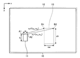
- two decoded images at different times are selected as reference images from among the encoded images (decoded images), and one of the first reference images 10 is selected as shown in FIG. It is determined at which position in the second reference image 12 the partial area, which is the area of the part, has moved. Movement direction and movement amount of the partial region is represented by motion vectors (Motion Vector) v 0. Then, based on the determined motion vector v 0, predicts an image to be encoded.
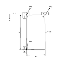
- a PU (Prediction Unit) 11 indicating a partial region in FIG. 1 is an example of a partial region in the present disclosure. It is assumed that the PU 11 is a rectangular area having a width w and a height h.
- the motion vector v 0 is a vector connecting the point A1 inside the PU 11 and the corresponding point of the point A1 inside the second reference image 12.
- the point corresponding to the point A1 in the second reference image 12 is, for example, a region having a high grayscale distribution that is highly correlated with the grayscale distribution around the point A1 in the first reference image 10 from the second reference image 12. Detect by searching.
- FIG. 1 is an example in which a point B1 is detected from the second reference image 12 as a corresponding point to the point A1 at the upper left of the PU 11.
- the point set inside the PU 11 to detect the corresponding point is not limited to the upper left point of the PU 11.
- the first reference image 10 and the second reference image 12 are searched for corresponding points in a state where the vertices of the respective images are matched, but FIG. 1 shows the first reference image 10 for explanation. And the second reference image 12 are slightly shifted.
- Such a search for a corresponding point is a method that is often used in image processing, for example, in a corresponding point search process for a left and right image of a stereo camera, and a detailed description thereof will be omitted.
- the first reference image 10 and the second reference image 12 are examples of images according to the present disclosure.
- one motion vector v 0 (v 0x , v 0y ) connecting both corresponding points is determined.
- one motion vector v 0 (v 0x , v 0y ) connecting the point A1 and the point B1 is determined.
- This state is referred to as a state in which two parameters are detected. That is, in order to determine the single motion vector v 0 may detect two parameters (one set of corresponding points).
- FIG. 1 it is interpreted that the PU 11 translates and moves to the corresponding block 13. That is, by detecting one set of corresponding points (two points) with respect to the PU 11, translational movement occurring in the partial area (PU11) can be detected.
- FIG. 2 is a first diagram illustrating an inter prediction process for performing motion compensation based on two motion vectors.
- FIG. 2 is a diagram illustrating a case where the partial area (PU11) formed in the first reference image 10 performs translation and rotation.
- FIG. 2 is an example in which the motion vectors v 0 (v 0x , v 0y ) and v 1 (v 1x , v 1y ) are determined.
- This state is referred to as a state in which four parameters are detected. That is, in order to determine two motion vectors v 01 and v 02 , four parameters (two sets of corresponding points) may be detected.
- FIG. 2 it is interpreted that the PU 11 translates and then rotates and moves by the rotation angle ⁇ and moves to the corresponding block 13.
- FIG. 3 is a second diagram illustrating an inter prediction process for performing motion compensation based on two motion vectors.
- FIG. 3 is a diagram illustrating a case where the partial area (PU11) formed in the first reference image 10 performs translation and scaling.
- FIG. 3 is an example in which the motion vectors v 0 (v 0x , v 0y ) and v 1 (v 1x , v 1y ) are determined.
- This state is also a state in which four parameters are detected.
- the PU 11 translates and then scales up and down by the magnification s (s> 1 indicates enlargement and s ⁇ 1 indicates reduction) and moves to the corresponding block 13. Will be interpreted.
- FIG. 4 is a third diagram illustrating an inter prediction process for performing motion compensation based on three motion vectors.
- FIG. 4 is a diagram illustrating a case where the partial area (PU11) formed in the first reference image 10 performs translation and skew deformation.
- FIG. 4 is an example in which the motion vectors v 0 (v 0x , v 0y ), v 1 (v 1x , v 1y ), and v 2 (v 2x , v 2y ) are determined.
- This state will be referred to as a state where six parameters are detected. That is, in order to determine three motion vectors v 0 , v 1 , and v 2 , six parameters (three sets of corresponding points) may be detected.
- FIG. 4 it is interpreted that the PU 11 translates and then skews at the shear angle ⁇ and moves to the corresponding block 13. That is, by detecting three sets of corresponding points with respect to the PU 11, it is possible to detect a movement including translation, rotation, enlargement / reduction, and skew deformation occurring in the partial area (PU11).
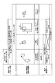
- FIG. 5 is a diagram showing the number of parameters detected from the reference image, the types of motion that can be detected, and the motion compensation mode. As shown in FIG. 5, as the number of detected parameters increases to 2, 4 (3), and 6, the types of motion that can be detected are expanded. That is, as the number of detected parameters increases, the accuracy of the predicted image improves. However, with an increase in the number of parameters to be detected, the calculation cost of the corresponding point search increases and the amount of codes to be transmitted increases, so that the overhead increases and the coding efficiency decreases.
- the translation mode is a mode for compensating for the movement that occurs with the translation (parallel movement).
- the translation rotation mode is a mode for compensating for the movement occurring due to the combination of the translation movement and the rotation movement.
- the translation scaling mode is a mode for compensating for a motion that occurs with a combination of translation and scaling.
- the affine transformation mode is a mode for compensating for a motion generated by a combination of translation, rotation, scaling, and skew.
- FIG. 6 is a diagram illustrating block division in HEVC (High Efficiency Video Coding).
- coding processing is executed in processing units called macroblocks.
- the macro block is a block having a uniform size of, for example, 16 ⁇ 16 pixels.
- HEVC Joint Photographic Experts Group 2
- coding processing is executed in a processing unit called a coding unit (CU: Coding @ Unit).
- CU Coding unit
- PU prediction unit
- a transform process for performing an orthogonal transform described later is executed in a process unit called a transform unit (TU: Transform @ Unit).
- TU Transform @ Unit
- LCU Large Coding Unit
- PU Physical Unit
- TU Physical Unit
- the PU and the TU are each divided on the basis of a quadtree.
- AMP Asymmetric Motion Partition
- Tolerate By allowing such asymmetric block division, the degree of freedom in dividing an image into regions is improved. Therefore, it is possible to generate a prediction block that matches the moving object in the image, and it is possible to improve the motion prediction performance.
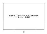
- FIG. 7 to FIG. 10 are diagrams for explaining a specific state of occurrence of a motion that occurs in each PU in an image.
- the image 64 includes an area 64A where the translation and the scaling have occurred between the two reference images, an area 64B where the translation and the rotation have occurred, the translation and the scaling, And an area 64C in which movement in the rotation direction has occurred, and an area 64D in which only translation has occurred.
- the inter prediction processing of the PU in the region 64C it is desirable to perform motion compensation in the translation rotation mode or the translation scaling mode.
- motion compensation may be performed in the rotation scaling mode.
- motion compensation may be performed in the translation mode.
- the state of the motion to be predicted is translation
- the present disclosure applies such a concept to reduce overhead and improve coding efficiency.
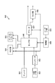
- FIG. 11 is a functional block diagram illustrating a configuration example of an embodiment of an image encoding device 100a as an example of an image processing device to which the present disclosure is applied.
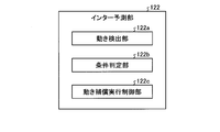
- FIG. 12 is a functional block diagram illustrating an example of a detailed functional configuration of the motion prediction unit 123 of the image encoding device 100a.
- Each function described in FIG. 11 includes, for example, a CPU 801 and a storage device such as a ROM 802 and a RAM 803 as illustrated in FIG. 28 described below, and executes a program stored in the ROM 802 or the RAM 803. It is also possible to realize the functions of each unit described later of the image encoding device 100a. In addition, some or all of the functions of each unit illustrated in FIG. 11 can be realized by dedicated hardware.
- the image encoding device 100a is a so-called video encoder that encodes a prediction residual between an image and a prediction image of the image, such as AVC or HEVC.
- the image encoding device 100a implements, for example, a technology proposed by HEVC or a technology proposed by JVET.
- FIG. 11 shows only main components such as the processing unit and the flow of data, and the components shown in FIG. 11 are not necessarily all components. That is, in the image encoding device 100a illustrated in FIG. 11, a processing unit that is not illustrated as a block may exist, or a process or a data flow that does not illustrated as an arrow or the like may exist.
- the image encoding device 100a encodes an image (video) by an inter prediction process or an intra prediction process as necessary.
- the intra prediction process is a so-called intra-frame prediction in which a prediction is performed using only information included in one reference image.
- the encoded moving image has a GOP (Group @ Of @ Pictures) structure, and includes, for example, prediction from an I picture coded by intra prediction, a P picture coded by inter prediction, and an I picture and a B picture. And a B picture.
- the image coding apparatus 100a sets the motion compensation mode of the motion compensation performed in the inter prediction process to a motion state (translation, rotation, enlargement / reduction, skew, and a motion obtained by combining them) occurring in the reference image. Accordingly, appropriate motion compensation for compensating the detected motion is performed.
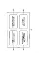
- the image coding apparatus 100a includes a control unit 101, an AD conversion unit 102, a calculation unit 110, an orthogonal transformation unit 111, a quantization unit 112, a coding unit 113, an inverse quantization unit 114, and an inverse orthogonal transformation unit 115. , An operation unit 116, and a frame memory 117. Further, the image encoding device 100 includes a selection unit 120, an intra prediction unit 121, and an inter prediction unit 122.
- the image encoding device 100a encodes an input video signal (moving image) in frame units for each of a plurality of CUs (or PUs) formed inside the image.
- the control unit 101 sets various coding parameters (header information Hinfo, prediction information Pinfo, conversion information Tinfo, and the like) based on an external input, an RD (Rate @ Distortion) cost, and the like. Then, the control unit 101 supplies parameters necessary for each block in FIG. 11 to the corresponding block among these coding parameters.
- the header information Hinfo is information for defining various initial values necessary for encoding a video signal.
- the header information Hinfo includes, for example, information such as a video parameter set, a sequence parameter set, a picture parameter set, and a slice header. Further, the header information Hinfo includes information defining the image size, the bit depth, the maximum value and the minimum value of the CU size, and the like. Note that the content of the header information Hinfo is arbitrary, and information other than the above example may be included in the header information Hinfo.
- the prediction information Pinfo includes, for example, a split flag indicating whether or not there is horizontal or vertical division in each division hierarchy when a PU (CU) is formed. Further, the prediction information Pinfo includes, for each PU, mode information pred_mode_flag indicating whether the prediction process in the PU is the intra prediction process or the inter prediction process.
- the prediction information Pinfo includes a merge flag, motion compensation mode information, parameter information, reference image specifying information for specifying a reference image, and the like.
- the $ merge flag is information indicating whether the mode of the inter prediction process is a merge mode or an AMVP (Adaptive Motion Vector Prediction) mode.
- the merge flag is, for example, 1 when indicating the merge mode, and is 0 when indicating the AMVP mode.
- the image encoding device 100a operates in one of the merge mode and the AMVP mode.
- the merge mode is a process based on parameters (motion vector, rotation angle information, scaling information, etc .; hereinafter referred to as adjacent parameters) used for motion compensation in an encoded PU adjacent to the processing target PU.
- This is a mode in which inter prediction processing of the target PU is performed.
- the AMVP mode is a mode in which inter prediction processing of a PU to be processed is performed based on parameters used for motion compensation of the PU.
- the motion compensation mode is information indicating whether the state of motion in the partial area to be predicted (PU or CU to be processed) is any of the above-described translation mode, translation rotation mode, translation scaling mode, or affine transformation mode. is there.
- the parameter information is information that specifies, when the merge flag is 1, parameters used for inter prediction processing from among candidates including adjacent parameters as prediction parameters (prediction vector, prediction rotation angle information, prediction scaling information). is there.
- the merge flag is information indicating a prediction parameter and information indicating a difference between the prediction parameter and a parameter of a processing target PU.
- the conversion information Tinfo includes information such as the size of the TU.
- the content of the conversion information Tinfo is arbitrary, and any information other than the size of the TU may be included in the conversion information Tinfo.
- the RD cost is a parameter that is calculated after encoding and that indicates the degree of encoding.
- the RD cost is calculated from, for example, an encoding distortion calculated based on a square error between an actually observed image and a predicted image and an encoding cost. The lower the RD cost is, the smaller the difference between the actually observed image and the predicted image is, that is, it indicates that efficient coding is being performed.
- the image coding apparatus 100a evaluates the degree of coding based on the RD cost, changes the coding parameter according to the evaluation result, and adopts a coding parameter with a lower RD cost.
- the AD conversion unit 102 performs AD conversion on a frame-by-frame video signal input as an input signal for each frame.
- a predetermined value is used as information necessary for performing AD conversion such as the number of quantization bits and the sampling frequency.
- the operation unit 110 functions as a difference operation unit, and calculates the difference between the predicted image P supplied from the selection unit 120 and the image to be encoded that has been AD-converted by the AD conversion unit 102.
- the operation unit 110 supplies the image obtained as a result of the subtraction to the orthogonal transformation unit 111 as a prediction residual image D.
- the orthogonal transform unit 111 performs an orthogonal transform such as a discrete cosine transform or a Karhunen-Loeve transform on the prediction residual image D supplied from the arithmetic unit 110 based on the transform information Tinfo supplied from the control unit 101. . Then, the orthogonal transform unit 111 supplies the transform coefficient Coeff obtained as a result of the orthogonal transform to the quantization unit 112.
- an orthogonal transform such as a discrete cosine transform or a Karhunen-Loeve transform
- the quantization unit 112 scales (quantizes) the transform coefficient Coeff supplied from the orthogonal transform unit 111 based on the transform information Tinfo supplied from the control unit 101, and calculates a quantized transform coefficient level level. Then, the quantization unit 112 supplies the quantized transform coefficient level level to the encoding unit 113 and the inverse quantization unit 114. The quantization unit 112 quantizes the transform coefficient Coeff obtained by the orthogonal transform using the number of quantization levels according to the quantization parameter (QP: Quantization Parameter). In general, the larger the value of QP (QP value), the higher the compression ratio.
- QP Quantization Parameter
- the encoding unit 113 encodes the quantized transform coefficient level supplied from the quantization unit 112 by a predetermined method. For example, the encoding unit 113 supplies the encoding parameters (header information Hinfo, prediction information Pinfo, conversion information Tinfo, and the like) supplied from the control unit 101 and the quantization unit 112 according to the definition of the syntax table. Is converted into a syntax value of each syntax element. Then, the encoding unit 113 encodes each syntax value. As a specific encoding method, for example, CABAC (Context-based Adaptive Binary Arithmetic Coding) or the like is used.
- CABAC Context-based Adaptive Binary Arithmetic Coding
- the coding unit 113 switches the context of the CABAC probability model based on the motion compensation mode information of the adjacent PU, and sets the CABAC probability model so that the probability of the motion compensation mode information of the adjacent PU becomes higher. Then, the motion compensation mode information of the PU is encoded.
- encoding section 113 sets a CABAC probability model to encode the motion compensation mode information of the PU so that the probability of the motion compensation mode information of the PU adjacent to the PU encoding the motion compensation mode information is increased. You may. As a result, overhead can be reduced and coding efficiency can be improved.
- the coding unit 113 may set a CABAC probability model based on the appearance frequency of each adjacent PU for each motion compensation mode information. Also, the encoding unit 113 may switch the code (bit string) to be assigned to the motion compensation mode information, instead of switching the context of the CABAC probability model based on the motion compensation mode information.
- the encoding unit 113 multiplexes, for example, encoded data that is a bit string of each syntax element obtained as a result of encoding, and outputs a bit stream as an encoded video signal.
- the inverse quantization unit 114 scales (inversely quantizes) the value of the quantized transform coefficient level supplied from the quantization unit 112 based on the transform information Tinfo supplied from the control unit 101, and performs inverse quantization. Is calculated.
- the inverse quantization unit 114 supplies the transform coefficient Coeff_IQ to the inverse orthogonal transform unit 115. Note that the inverse quantization performed by the inverse quantization unit 114 is an inverse process of the quantization performed by the quantization unit 112.
- the inverse orthogonal transform unit 115 performs an inverse orthogonal transform or the like on the transform coefficient Coeff_IQ supplied from the inverse quantization unit 114 based on the transform information Tinfo supplied from the control unit 101, and generates a prediction residual image D ′. calculate.
- the inverse orthogonal transform unit 115 supplies the prediction residual image D ′ to the calculation unit 116. Note that the inverse orthogonal transform performed by the inverse orthogonal transform unit 115 is an inverse process of the orthogonal transform performed by the orthogonal transform unit 111.
- the arithmetic unit 116 adds the prediction residual image D ′ supplied from the inverse orthogonal transform unit 115 and the prediction image P corresponding to the prediction residual image D ′ supplied from the inter prediction unit 122, and Calculate the decoded image Rec. Then, the arithmetic unit 116 supplies the local decoded image Rec to the frame memory 117.
- the frame memory 117 reconstructs a decoded image in units of pictures using the locally decoded image Rec supplied from the arithmetic unit 116 and stores the reconstructed image in the frame memory 117.
- the frame memory 117 reads the decoded image specified by the inter prediction unit 122 from the frame memory 117 as a reference image, and supplies the reference image to the inter prediction unit 122 and the motion prediction unit 123. Further, the frame memory 117 may store header information Hinfo, prediction information Pinfo, conversion information Tinfo, and the like related to generation of a decoded image in a buffer in the frame memory 117.
- the intra prediction unit 121 acquires a decoded image at the same time as the encoding target CU stored in the frame memory 117 as a reference image. Then, the intra prediction unit 121 performs an intra prediction process on the encoding target PU using the reference image.
- the inter prediction unit 122 acquires a decoded image at a time different from the encoding target CU stored in the frame memory 117 as a reference image based on the reference image specifying information. I do. Further, the inter prediction unit 122 detects a motion vector in the CU to be encoded, predicts a motion state of the CU, and generates motion compensation mode information in the CU. Then, the inter prediction unit 122 performs inter prediction processing on the encoding target PU by performing motion compensation on the reference image based on the merge flag, the motion compensation mode information, the parameter information, and the like.
- the inter prediction unit 122 includes a plurality of motion compensation modes for compensating for a state of motion occurring with time in a CU (partial area) indicating a partial area of an image, and In addition to the detection, the predicted image P is generated by compensating the state of the detected motion.
- the image encoding device 100a has the above-described translation mode, translation rotation mode, translation scaling mode, and affine transformation mode as the plurality of motion compensation modes.
- the selection unit 120 supplies the predicted image P generated as a result of the intra prediction process or the inter prediction process to the calculation unit 110 and the calculation unit 116.
- the inter prediction unit 122 includes a motion detection unit 122a, a condition determination unit 122b, and a motion compensation execution control unit 122c.
- the motion detection unit 122a is an example of a motion compensation unit according to the present disclosure.
- the motion detection unit 122a includes a plurality of motion compensation modes for compensating for a state of a motion occurring with time in a partial region (for example, a PU) indicating a partial region of an image.
- a predicted image P is generated by detecting the state and compensating the detected state of the motion.
- the condition determination unit 122b determines the position and the direction of the motion vector at a maximum of three vertices of the rectangular partial area detected by the motion detection unit 122a (motion compensation unit), and the width and the height of the partial area. Whether the state of movement of the region satisfies a predetermined condition, that is, the state of movement of the partial region involves translation and rotation, involves translation and scaling, or translation and rotation, It is determined whether enlargement / reduction and skew deformation are involved.
- the motion compensation execution control unit 122c is an example of an execution control unit according to the present disclosure.
- the motion compensation execution control unit 122c gives the motion detecting unit 122a a motion compensation mode corresponding to the predetermined condition. To skip.
- the motion compensation execution control unit 122c determines that the predetermined condition is that the motion state of the partial area detected by the motion detection unit 122a involves translation and rotation, and that the predetermined condition is satisfied.
- the predetermined condition is that the motion state of the partial area detected by the motion detection unit 122a involves translation and rotation, and that the predetermined condition is satisfied.
- a translation scaling mode that compensates for motion involving translation and scaling
- an affine transformation mode that compensates for motion that involves translation, rotation, scaling, and skew deformation
- the motion compensation execution control unit 122c determines that the predetermined condition is that the state of the motion of the partial area detected by the motion detection unit 122a involves translation and enlargement / reduction.
- the condition is satisfied, a translation rotation mode for compensating for a motion involving translation and rotation, and an affine transformation mode for compensating for a motion involving translation, rotation, scaling and skew deformation for the motion detection unit 122a. And skip.
- the motion compensation execution control unit 122c sets the condition determination unit 122b such that the predetermined condition is that the motion state of the partial area detected by the motion detection unit 122a involves translation, rotation, scaling, and skew deformation. And a translation scaling mode for compensating a motion involving translation and scaling, and a translation for compensating for motion involving translation and rotation, when the predetermined condition is satisfied. Rotate mode and skip.
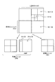
- FIG. 13 is a diagram illustrating the merge mode.
- the motion detection unit 122a converts the prediction vector pv 0 at the upper left vertex A of the prediction target PU 11 in FIG. It is determined based on the motion vector in the neighboring area. That is, in FIG. 13, a prediction vector predicted at the vertex A based on motion vectors in the upper left neighboring area a of the vertex A, the upper right neighboring area b of the vertex A, and the lower left neighboring area c of the vertex A, respectively. Determine pv 0 .
- the motion detecting unit 122a the prediction vector pv 1 in the upper right apex B of PU11, is already already coded is determined based on the motion vector in the region near the vertex B. That is, in FIG. 13, the region near the upper left vertex B d, based on the motion vector in each of the upper right of the neighboring region e of the vertex B, and determines a prediction vector pv 1 at vertex B. Then, for the predicted vector pv 2 at the vertex C of the lower left PU11, likewise, the area near f of the vertex C, is determined based on the motion vector in the neighboring region g. It is assumed that the motion vectors detected in the neighboring areas a to g are held in the motion detecting unit 122a.
- the motion prediction unit 123 determines, as a motion vector at the vertices A, B, and C, among the twelve combinations of candidates, the combination that minimizes the cost DV obtained by the following equation (1).
- v 0x ′ and v 0y ′ are the x-direction component and the y-direction component of the motion vector in any of the neighboring regions a to c used for determining the prediction vector pv 0 .
- v 1x in the formula (1) ', v 1y' is a x-direction component and the y-direction component of the motion vector in one of the neighboring region d and the adjacent region e is used for determining the prediction vector pv 1.
- v 2x in the formula (1) ', v 2y' is a x-direction component and the y-direction component of the motion vector in one of the neighboring region f and the adjacent region g is used for determining the prediction vector pv 2.
- the motion detection unit 122a uses the result of motion compensation in a plurality of motion-compensated neighboring regions located in the vicinity of the partial region to calculate the motion of the partial region. To generate the predicted image.
- the motion compensation execution control unit 122c applies the occurrence frequency of the motion compensation mode used for motion compensation of the plurality of neighboring regions and the motion compensation mode used for motion compensation of the plurality of neighboring regions to the partial region.
- the motion state in the partial area is detected based on the cost (RD cost) indicating the degree of prediction of the predicted image P generated by performing the motion compensation.
- the motion detection unit 122a calculates the RD cost in the order of the occurrence frequency of the motion compensation mode in a plurality of neighboring regions.
- the predetermined condition is that the motion state of the partial region involves translation and rotation, and the motion compensation execution control unit 122c Is satisfied, a translation scaling mode for compensating for a motion involving translation and scaling, and an affine for compensating for a motion involving translation, rotation, scaling and skew deformation for the motion detection unit 122a. Conversion mode and skip.
- the motion compensation execution control unit 122c determines that the predetermined condition is that the motion state of the partial region is accompanied by translation and scaling.
- a translation rotation mode for compensating for a motion involving translation and rotation
- an affine for compensating for a motion involving translation, rotation, scaling, and skew deformation for the motion detection unit 122a. Conversion mode and skip.
- the motion compensation execution control unit 122c determines that the predetermined condition is that the motion state of the partial area is translation, rotation, scaling, and skew deformation.
- the motion detecting unit 122a compensates for the translational scaling mode and the translational scaling mode. And the translation rotation mode.
- the motion compensation mode information includes, for example, affine_flag, affine3parameter_flag, and rotate_scale_idx.
- affine_flag (affine transformation information) is information indicating whether the motion compensation mode is an affine transformation mode other than the translation mode, a translation scaling mode, or a translation rotation mode.
- the affine_flag is set to 1, for example, when the motion compensation mode is the affine transformation mode, the translation rotation mode, or the translation scaling mode.
- affine_flag is set to 0 when the motion compensation mode is not the affine transformation mode, the translation rotation mode, and the translation scaling mode, that is, when the motion compensation mode is the translation mode.
- Affine3parameter_flag (translation extended information) is information indicating whether the motion compensation mode is the translation scaling mode or the translation rotation mode, and is set when affine_flag is 1.
- affine3parameter_flag is set to 1 when the motion compensation mode is the translation scaling mode or the translation rotation mode.
- affine3parameter_flag is set to 0 when the motion compensation mode is not the translation rotation mode or the translation scaling mode, that is, when the motion compensation mode is the affine transformation mode.
- Rotate_scale_idx (translation rotation information) is information indicating whether the motion compensation mode is the translation rotation mode, and is set when affine3parameter_flag is 1.
- rotate_scale_idx is set to 1 when the motion compensation mode is the translation rotation mode.
- the motion compensation mode is not the translation rotation mode, that is, when the motion compensation mode is the translation scaling mode, 0 is set.
- the motion compensation mode information is constituted by affine_flag, and affine_flag is 0.
- the motion compensation mode information is composed of affine_flag and affine3parameter_flag, affine_flag is 1, and affine3parameter_flag is 0.
- the motion compensation mode information is composed of affine_flag, affine3parameter_flag, and rotate_scale_idx.
- affine_flag and affine3parameter_flag are 1 and rotate_scale_idx is 0.
- rotate_scale_idx is 0.
- the prediction information Pinfo includes intra prediction mode information indicating the intra prediction mode.
- the content of the prediction information Pinfo is arbitrary, and any information other than the example described above may be included in the prediction information Pinfo.
- one motion vector v 0 of the processing target PU that is, a prediction vector corresponding to the motion vector v 0 of the vertex A of the PU.
- Information specifying pv 0 is set as parameter information refidx0, and a difference between one of the motion vectors v 0 and prediction vector pv 0 is set as parameter information mvd0.
- the parameter information refidx0 and mvd0 are set as in the case of the translation mode. Further, information specifying predicted angle information corresponding to the angle information of the processing target PU 11 is set as refidx1 of the parameter information, and a difference between the angle information and the predicted angle information is set as dr of the parameter information.
- dr is the difference d ⁇ between the rotation angle ⁇ of the processing target PU 11 and the rotation angle ⁇ ′ as the predicted angle information.
- dr is the difference mvd1.y between the difference dvy of the processing target PU 11 and the difference dvy as the predicted angle information.
- refidx0 and mvd0 of the parameter information are set as in the case of the translation mode.
- information that specifies predicted scaling information corresponding to the scaling information of the processing target PU 11 is set as refidx1 of the parameter information, and the difference between the scaling information and the predicted scaling information is set as ds of the parameter information.
- ds is a difference ds between the scaling factor s of the processing target PU 11 and the scaling factor s as the prediction scaling information.
- ds is the difference mvd1.x between the difference dvx of the processing target PU 11 and the difference dvx as the prediction scaling information.
- refidx0 and mvd0 of the parameter information are set as in the case of the translation mode. Further, information specifying another motion vector v 1 of the processing target PU 11, that is, a prediction vector pv 1 corresponding to the motion vector v 1 of the vertex B of the PU 11 is set as refidx1 of the parameter information. 1 and the difference between the prediction vector pv 1 is set as mvd1 parameter information.
- refidx0 and mvd0 and refidx1 and mvd1 of the parameter information are set as in the case of the translation rotation mode or the translation scaling mode. Further, information for specifying still another motion vector v 2 of the processing target PU 11, that is, information for specifying the prediction vector pv 2 corresponding to the motion vector v 2 of the vertex C of the PU 11 is set as refidx2 of the parameter information. v 2 the difference between the predicted vector pv 2 is set as mvd2 parameter information.
- the mode of the inter prediction process is the merge mode
- the above-described mvd0, mvd1, mvd2, ds, dr, refidx0, refidx1, and refidx2 are not set.
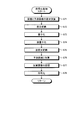
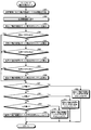
- FIG. 14 is a flowchart illustrating an example of the flow of a process performed by the image encoding device 100a.
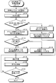
- FIGS. 15 to 17 and 19 are flowcharts showing the detailed flow of the main processing shown in FIG. Specifically, FIG. 15 is a flowchart illustrating an example of a flow of a process in which the image encoding device 100a estimates the RD cost in the inter prediction mode.
- FIG. 16 is a flowchart illustrating an example of the flow of the motion prediction process in the AMVP mode performed by the image encoding device 100a.
- FIG. 17 is a flowchart illustrating an example of the flow of an encoding process performed by the image encoding device 100a.
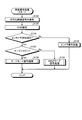
- FIG. 19 is a flowchart illustrating an example of the flow of the motion prediction process in the merge mode performed by the image encoding device 100a.
- step S10 of FIG. 14 the control unit 101 sets encoding parameters (header information Hinfo, prediction information Pinfo, conversion information Tinfo, and the like).
- step S11 the condition determination unit 122b determines whether the merge flag is 0. If it is determined in step S11 that the merge flag is 1 (step S11: Yes), the process proceeds to step S12. On the other hand, if it is not determined in step S11 that the merge is 1 (step S11: No), the process proceeds to step S19.
- step S12 the motion detection unit 122a reads the reference image stored in the frame memory 117 and divides the CU in order to perform motion prediction. Specifically, the motion detection unit 122a divides the reference image into regions that are likely to be motion generation units. At this time, the CU is divided according to the method described with reference to FIG. The area division as a unit of occurrence of motion is performed using a known image processing method, such as merging pixels having similar pixel values into one area.
- step S13 the intra prediction unit 121 estimates the RD cost of the intra prediction mode.
- step S14 the motion compensation execution control unit 123c estimates the RD cost of the inter prediction mode.
- the detailed processing flow in step S14 will be described later (FIG. 15).
- step S15 the condition determination unit 122b determines the mode having the minimum RD cost among the calculated RD costs to be the motion compensation mode.
- the process performed in step S15 is performed when the estimation of the RD cost is not completed early in step S14.
- step S14 when the estimation of the RD cost ends early, the condition determining unit 122b applies a motion compensation mode corresponding to the state ended early to the motion compensation according to the determination. Details will be described in the description of FIG. 15 described later.
- step S16 the inter prediction unit 122 performs motion prediction in the motion compensation mode determined in step S15 (or the motion compensation mode determined in step S14).
- the detailed flow of the process in step S16 will be described later (FIG. 16).
- the intra prediction process is executed instead of step S16.
- step S17 the orthogonal transformation unit 111, the quantization unit 112, the encoding unit 113, and the like perform the encoding process in cooperation.
- the detailed processing flow in step S17 will be described later (FIG. 17).
- step S18 the condition determination unit 122b determines whether the encoding process has been performed on all the CUs in the image to be encoded.
- step S18 when it is determined that the encoding process has been performed on all CUs in the image (step S18: Yes), the image encoding device 100a ends the process in FIG. On the other hand, if it is not determined in step S18 that the encoding process has been performed on all the CUs in the image (step S18: No), the process returns to step S13, and steps S13 to S18 are performed for the next PU. repeat.
- step S19 the motion detection unit 122a reads the reference image and performs CU division. Note that the processing performed here is the same as the processing described in step S12.
- step S20 the motion detection unit 122a performs motion prediction in the merge mode.
- the detailed flow of the process in step S20 will be described later (FIG. 19).
- step S21 the orthogonal transformation unit 111, the quantization unit 112, the encoding unit 113, and the like perform the encoding process in cooperation.
- the detailed flow of the process in step S21 will be described later (FIG. 17).
- step S22 the condition determination unit 122b determines whether the encoding process has been performed on all the CUs in the image to be encoded.
- step S22 when it is determined that the encoding process has been performed on all the CUs in the image (step S22: Yes), the image encoding device 100a ends the process in FIG. On the other hand, if it is not determined in step S22 that the encoding process has been performed on all the CUs in the image (step S22: No), the process returns to step S20, and steps S20 to S22 are performed for the next PU. repeat.
- step S31 in FIG. 15 the motion compensation execution control unit 122c assumes that a translation has occurred in the target CU, and calculates the RD cost J RD2 when encoding based on normal inter prediction, that is, The RD cost when the motion compensation estimated by two parameters is performed is calculated.
- step S32 the motion compensation execution control unit 122c calculates the RD cost J RD6A when the target CU is encoded on the assumption that the motion described in the affine transformation mode has occurred, that is, 6
- the RD cost when the motion compensation estimated by the parameter is performed is calculated.
- the motion compensation execution control unit 122c calculates an evaluation cost JA4 when performing motion compensation on the target CU in the affine transformation mode.
- the evaluation cost JA4 is calculated by, for example, the following equation (2).
- Estimation cost J A4 represents the degree to which the CU as an object undergoing skew deformation. That indicates that there is a high possibility that the larger the evaluation cost J A4, CU as an object is subjected to skew deformation.
- step S34 condition determination unit 122b, estimation cost J A4 calculated in step S33 it is determined greater than the predetermined threshold value J THA4.
- step S34 if J A4 > J THA4 (step S34: Yes), the process returns to the main routine (the flowchart of FIG. 14). If it is determined in step S34 that J A4 > J THA4, it is determined that there is a high possibility that the target CU has undergone skew deformation. Then, the motion compensation execution control unit 122c determines that motion compensation in the affine transformation mode (6 parameter motion compensation) is applied to the target CU. Then, the processing in FIG. 15 is terminated early and the process returns to the main routine in FIG. 14, thereby speeding up the processing. That is, in this case, the motion compensation in the translation mode, the translation rotation mode, and the translation scaling mode is set to be skipped.
- step S34 when it is determined as Yes in step S34, a flag indicating that the RD cost estimation process has been terminated early is set, and the motion compensation in the affine transformation mode is applied. After adding the indicated information, the process returns to the main routine of FIG. In step S15 of FIG. 14, when a flag indicating that the RD cost estimation process has been terminated early is set, and when information indicating that motion compensation in the affine transformation mode is to be applied is added, The motion compensation performed in step S16 is performed in the affine transformation mode.
- step S34 No
- the process proceeds to step S35.
- the motion compensation execution control unit 122c calculates the RD cost J RD4A when the target CU is coded assuming that the motion described in the translation rotation mode or the translation scaling mode has occurred. That is, the RD cost when the motion compensation estimated using the 4 (3) parameters is performed is calculated.
- step S36 the motion compensation execution control unit 122c evaluates the evaluation cost J R3 when performing motion compensation in the translation rotation mode on the target CU and performs motion compensation in the translation scaling mode. Is calculated respectively.
- the evaluation cost JR3 is calculated by, for example, the following equation (3).
- the evaluation cost JR3 represents the degree to which the target CU is performing translational rotation. That is, the higher the evaluation cost JR3, the higher the possibility that the target CU is performing translational rotation.
- the evaluation cost JS3 is calculated by, for example, the following equation (4).
- Estimation cost J S3 represents the degree to CU as an object is moving translation scaling. That is, the larger the evaluation cost J S3, indicates an increased likelihood that CU as an object is moving translation scaling.
- step S37 the condition determining unit 122b, an evaluation cost J S3 calculated in step S36 it is determined greater than the predetermined threshold value J THS3. If it is determined in step S37 that J S3 > J THS3 (step S37: Yes), the process proceeds to step S39. If it is determined in step S37 that J S3 > J THS3, it is determined that there is a high possibility that the target CU has undergone translational scaling movement.
- step S37 if J S3 > J THS3 is not satisfied (step S37: No), the process proceeds to step S38.
- the motion compensation execution control unit 122c calculates the RD cost J RDS3 when the target CU is coded assuming that the motion described in the translation scaling mode has occurred, that is, 4 (3 )
- the RD cost when the motion compensation estimated by the parameter is performed is calculated.
- step S39 the condition determining unit 122b, an evaluation cost J R3 calculated in step S36 it is determined greater than the predetermined threshold value J THR3.
- step S39 if it is J R3> J THR3 (step S39: Yes), the flow returns to the main routine (FIG. 14).
- step S39 if it is determined that J R3> J THR3, CU of interest is determined that there is a high possibility that the translation and rotation movement.
- the motion compensation execution control unit 122c determines that the motion compensation (4 (3) parameter motion compensation) in the translation rotation mode is applied to the target CU.
- the processing in FIG. 15 is terminated early, and the process returns to the main routine in FIG. 14, thereby speeding up the processing. That is, in this case, the motion compensation in the translation mode, the translation scaling mode, and the affine transformation mode is set to be skipped.
- step S39 if it is determined to be Yes in step S39, a flag indicating that the RD cost estimation process has been terminated early is set, and motion compensation in the translational rotation mode is applied. And returns to the main routine of FIG. In step S15 of FIG. 14, a flag indicating that the RD cost estimation process has been terminated early is set, and information indicating that motion compensation in the translational rotation mode is to be applied is added. Performs the motion compensation performed in step S16 in the translational rotation mode.
- step S37 If it is determined in step S37 that J S3 > J THS3 , there is a high possibility that the target CU has undergone translational scaling as described above. Therefore, the process may return to the main routine at the time of determining “Yes” in step S37, but there is a possibility that the target CU is performing translational rotation. Therefore, in the flowchart of FIG. 15, step S37 is determined to be “Yes”. Even if this is the case, step S39 is subsequently executed. However, in this case, the processing is speeded up by skipping step S38.
- step S39 if not J R3> J THR3 (step S39: No), the process proceeds to step S40.
- step S40 the condition determining unit 123b is again evaluated cost J S3 calculated in step S36 it is determined greater than the predetermined threshold value J THS3.
- This process is the same as the determination process performed in step S37, in the case of J S3> J THS3 and J R3 ⁇ J THR3, in order to terminate the determination of the motion compensation mode early, try again.
- step S40 if J S3 > J THS3 (step S40: Yes), the process returns to the main routine (FIG. 14). If it is determined in step S40 that J S3 > J THS3, it is determined that there is a high possibility that the target CU has undergone translational scaling movement. Then, the motion compensation execution control unit 123c determines that the motion compensation (4 (3) parameter motion compensation) in the translation scaling mode is applied to the target CU. Then, the processing in FIG. 15 is terminated early, and the process returns to the main routine in FIG. 14, thereby speeding up the processing. That is, in this case, the motion compensation in the translation mode, the translation rotation mode, and the affine transformation mode is set to be skipped.
- step S40 when it is determined to be Yes in step S40, a flag indicating that the RD cost estimation process has been terminated early is set, and the motion compensation by the translation scaling mode is applied. After adding the indicated information, the process returns to the main routine of FIG. If the flag indicating that the RD cost estimation process has been terminated early is set in step S15 of FIG. 14 and information indicating that motion compensation in the translational scaling mode is to be applied is added, The motion compensation performed in S16 is performed in the translation scaling mode.
- step S40 if J S3 > J THS3 is not satisfied (step S40: No), the process proceeds to step S41, and the motion compensation execution control unit 122c determines whether the motion described in the translation rotation mode is the target CU.
- FIG. 16 shows the flow of the process performed in step S16 of FIG. 14 in detail.
- the set motion compensation mode is specified.
- the motion compensation mode may be determined by referring to the above-described motion compensation mode information (affine_flag, affine3parameter_flag, rotate_scale_idx). In the following description, for the sake of simplicity, it is simply described as determining whether or not a specific motion compensation mode is set. The actual determination is made by referring to the status of each flag and index.
- step S51 the condition determination unit 122b determines whether the motion compensation mode is the translation mode. If it is determined that the motion compensation mode is the translation mode (step S51: Yes), the process proceeds to step S52. On the other hand, if it is not determined that the motion compensation mode is the translation mode (step S51: No), the process proceeds to step S55.
- step S52 the motion detection unit 122a, on the basis of the parameter information to determine the predicted vector pv 0. Specifically, when the parameter information is information for specifying an adjacent vector as a prediction vector, the motion detection unit 122a calculates a cost based on the stored motion vectors of the neighboring regions a to g (FIG. 13). DV is adjacent vectors generated from one of the motion vectors of the smallest neighboring region a to the region near c, determining the prediction vector pv 0.
- step S53 the motion detection unit 122a, a difference of one and the predicted vector pv 0 of which is determined in step S52, the motion vector v 0 of the prediction vector pv 0 and the processed PU of the parameter information dv 0 and the motion vector v 0 of the processing target PU are calculated.
- step S54 the inter prediction unit 122 uses the motion vectors v 0 calculated in step S53, in a translational mode for the reference image specified by the reference image identification information stored in the frame memory 117 Perform motion compensation.
- the motion detecting unit 122a supplies the motion-compensated reference image as the predicted image P to the arithmetic unit 110 and the arithmetic unit 116. Then, the process returns to the main routine (FIG. 14).
- step S55 the condition determination unit 122b determines whether the motion compensation mode is the affine transformation mode. If it is determined that the motion compensation mode is the affine transformation mode (step S55: Yes), the process proceeds to step S56. On the other hand, if it is not determined that the motion compensation mode is the affine transformation mode (step S55: No), the process proceeds to step S60.
- step S56 the motion detection unit 122a determines three prediction vectors pv 0 , pv 1 , and pv 2 based on the parameter information.
- step S57 the motion detection unit 122a corresponds to each of the three prediction vectors pv 0 , pv 1 , and pv 2 determined in step S46 and the prediction vectors pv 0 , pv 1 , and pv 2
- the three motion vectors v 0 , v 1 , and v 2 in the processing target PU 11 are obtained by adding the differences among the parameter information to be processed.
- Equation (5) w, h, x, and y represent the width and height of the PU 11, the position of the PU 11 in the x direction, and the position of the PU 11 in the y direction, respectively.
- the motion vector v in the PU 11 is obtained by proportionally distributing the motion vectors v 0 to v 2 according to the position (x, y) of the PU 11.
- step S59 the motion detection unit 122a performs affine transformation on the block of the reference image specified by the reference image specifying information based on the motion vector v for each unit block, thereby affine-converting the reference image. Perform motion compensation in conversion mode.
- the motion detection unit 122a supplies the reference image on which the motion compensation has been performed as the prediction image P to the calculation unit 110 or the calculation unit 116. Then, the process returns to the main routine (FIG. 14).
- step S60 the condition determination unit 122b determines whether the motion compensation mode is the translation rotation mode. If it is determined that the motion compensation mode is the translation rotation mode (step S60: Yes), the process proceeds to step S61. On the other hand, if it is not determined that the motion compensation mode is the translation rotation mode (step S60: No), the process proceeds to step S64.
- step S61 the motion detection unit 122a determines a prediction vector pv 0 of one on the basis of the parameter information. Further, the motion detection unit 123a determines predicted angle information based on the parameter information.
- step S62 the motion detection unit 122a calculates a single motion vector v 0 in the same way as the process of step S53.
- the motion detection unit 122a adds the prediction angle information determined in step S61 and the difference between the prediction angle information of the parameter information and the angle information of the processing target PU, thereby obtaining the processing target PU. Calculate angle information.
- step S63 the motion detection unit 122a, using a single motion vector v 0 and the angle information calculated in step S62, performs motion compensation in translation and rotation mode for the reference image.
- the motion detection unit 122a supplies the reference image on which the motion compensation has been performed as the prediction image P to the calculation unit 110 or the calculation unit 116. Then, the process returns to the main routine (FIG. 14).
- step S64 the motion detection unit 122a performs one process on the basis of the parameter information as in the process in step S52. Determine the prediction vector pv 0 . Further, the motion detection unit 122a determines the prediction magnification information based on the parameter information.
- step S65 the motion detection unit 123a calculates a single motion vector v 0 in the same way as the process of step S53. Further, the motion detection unit 123a adds the prediction magnification information determined in step S64 and the difference between the prediction magnification information of the parameter information and the magnification information of the processing target PU, thereby obtaining the processing target PU. Calculate magnification information.
- step S66 the motion detection unit 122a, using a single motion vector v 0 and magnification information calculated in step S65, performs motion compensation in translation scaling mode for the reference image.
- the motion detection unit 122a supplies the reference image on which the motion compensation has been performed as the prediction image P to the calculation unit 110 or the calculation unit 116. Then, the process returns to the main routine (FIG. 14).
- step S71 the calculation unit 110 calculates a difference between the encoding target image that has been AD-converted by the AD conversion unit 102 and the predicted image P.
- the calculation result is supplied to the orthogonal transformation unit 111 as a prediction residual image D.
- the data amount of the prediction residual image D thus obtained is reduced as compared with the image to be encoded. Therefore, the data amount can be reduced as compared with the case where the image to be encoded is encoded as it is.
- the orthogonal transform unit 111 performs orthogonal transform on the prediction residual image D supplied from the arithmetic unit 110 based on the transform information Tinfo supplied from the control unit 101, and calculates a transform coefficient Coeff. .
- the orthogonal transform unit 111 supplies the transform coefficient Coeff to the quantization unit 112. Note that the orthogonal transform unit 111 specifically performs an orthogonal transform represented by a discrete cosine transform (DCT) or the like.
- DCT discrete cosine transform
- step S73 the quantization unit 112 scales (quantizes) the transform coefficient Coeff supplied from the orthogonal transform unit 111 based on the transform information Tinfo supplied from the control unit 101, and sets the quantized transform coefficient level level. calculate.
- the quantization unit 112 supplies the quantized transform coefficient level “level” to the encoding unit 113 and the inverse quantization unit 114.
- step S74 the inverse quantization unit 114 sets the quantized transform coefficient level supplied from the quantization unit 112 based on the transform information Tinfo supplied from the control unit 101 to the quantization characteristic in step S73. Inverse quantization with the characteristic The inverse quantization unit 114 supplies the resulting transform coefficient Coeff_IQ to the inverse orthogonal transform unit 115.
- step S75 the inverse orthogonal transform unit 115 converts the transform coefficient Coeff_IQ supplied from the inverse quantization unit 114 into a method corresponding to the orthogonal transform in step S72 based on the transform information Tinfo supplied from the control unit 101. Perform an inverse orthogonal transform or the like to calculate a prediction residual image D ′.
- step S76 the calculation unit 116 generates the local decoded image Rec by adding the prediction residual image D ′ calculated in the processing in step S75 to the prediction image P supplied from the inter prediction unit 122. I do.
- step S77 the frame memory 117 reconstructs a decoded image for each picture using the locally decoded image Rec obtained by the processing in step S76, and stores the reconstructed image in a buffer in the frame memory 117.
- step S78 the encoding unit 113 encodes the encoding parameter set by the process of step S10 in FIG. 14 and the quantized transform coefficient level obtained by the process of step S73 by a predetermined method. .
- the encoding unit 113 multiplexes the encoded data obtained as a result and outputs the multiplexed data to the outside of the image encoding device 100a as an encoded stream. This encoded stream is transmitted to the decoding side via a transmission path or a recording medium, for example.
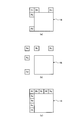
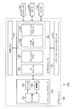
- FIG. 18 is a diagram illustrating an example of the neighborhood area set when performing the motion prediction process in the merge mode.
- FIG. 18A shows an example in which five motion-compensated (encoded) neighboring areas are set near a CU 14 (a CU 14 may be a PU) as a motion prediction target. That is, the CU 14 is an example of a partial region in the present disclosure.
- the neighboring regions Ra, Rb, and Re are regions that are adjacent to the CU 14 by eight at the upper left.
- the neighborhood area Ra is adjacent to the upper left vertex of the CU 14 at the lower left.
- the neighboring region Rb is adjacent to the upper right corner of the CU 14 at the upper right corner.
- the neighboring area Re is adjacent to the upper left vertex of the CU 14 at the upper left.
- the neighboring region Rc is adjacent to the upper left corner of the CU 14 at the upper left
- the neighboring region Rd is adjacent to the lower left vertex of the CU 14 at the upper left.
- the neighboring area may be set to four neighbors instead of eight neighbors. That is, in FIG. 18A, only four neighboring regions Ra, Rb, Rc, and Rd may be set.
- the condition determination unit 122b of the image encoding device 100a determines the state of the motion detected in the neighboring areas Ra to Re (translation mode, translation rotation (The mode, the translation scaling mode, and the affine transformation mode), the motion state of the CU 14 is determined in descending order of the frequency of the detected motion state. Then, the motion compensation execution control unit 122c (execution control unit) of the image encoding device 100a sets the condition that the condition determination unit 122b satisfies the predetermined condition, that is, determines that the condition of the predetermined motion has been detected. And skip the motion compensation mode according to the predetermined condition.
- the motion state in the CU 14 is predicted to be equal to the high-frequency motion state. In this way, by determining the state of movement in the order of appearance frequency, the state of movement can be determined early and the determination can be terminated.
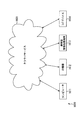
- the number of neighboring areas set near the CU 14 is not limited to five as shown in FIG. That is, as shown in FIG. 18C, more neighboring regions may be set, such as the neighboring regions Ra to Ri. As the number of neighboring areas to be set is larger, the number of motion states that can be referred to is increased. Therefore, the frequency of occurrence of highly reliable motion is further increased, so that the accuracy of motion prediction in the CU 14 can be improved. .
- the vicinity area set near the CU 14 does not necessarily need to be adjacent to the CU 14. That is, as shown in FIG. 18B, the vicinity area may be set at a position not adjacent to the CU. As described above, by setting the vicinity area at a position that is not adjacent to the CU 14, the state of movement in the CU 14 can be predicted based on the state of movement in a wider range near the CU 14.
- step S81 the motion detection unit 122a counts the number of appearances of the motion compensation mode in a region near (or adjacent to) the CU 14 to be predicted. That is, it counts how many neighboring areas (or adjacent areas) each of the motion compensation modes of the translation mode, the translation rotation mode, the translation scaling mode, and the affine transformation mode have occurred.
- the counting result is supplied to the condition determining unit 122b.
- step S82 the condition determination unit 122b arranges the results counted in step S81 in the order of the appearance frequency of the motion compensation mode.
- step S83 the motion compensation execution control unit 122c applies the motion compensation mode having the highest appearance frequency (hereinafter, referred to as order 1) to encode the CU 14 to be subjected to motion prediction. It calculates the RD cost J 1.
- step S84 the condition determination unit 122b determines whether or not to terminate the determination of the motion compensation mode to be applied to the CU 14 that is a target of motion prediction based on the result of order 1. If it is determined that the processing should be terminated based on the result of the order 1 (step S84: Yes), the process proceeds to step S90. On the other hand, if it is not determined that the operation is to be terminated based on the result of the order 1 (step S84: No), the process proceeds to step S85.
- truncating the result of order 1 for example, may be determined by RD cost J 1 falls below a predetermined threshold value J TH.
- step S85 the motion compensation execution control unit 122c applies a motion compensation mode in which the appearance frequency of the motion compensation mode is the second highest (hereinafter, referred to as order 2). It calculates the RD cost J 2 in the case of performing encoding of CU14 to be motion prediction.
- step S86 the condition determination unit 122b determines whether to terminate the determination of the motion compensation mode to be applied to the CU 14 that is a target of motion prediction, based on the result of the order 2. If it is determined that the processing should be terminated based on the result of the order 2 (step S86: Yes), the process proceeds to step S90. On the other hand, if it is not determined that the processing should be terminated based on the result of the order 2 (step S86: No), the process proceeds to step S87.
- truncating the result of order 2 for example, may be determined by RD cost J 2 falls below a predetermined threshold value J TH.
- step S87 the motion compensation execution control unit 122c applies a motion compensation mode in which the appearance frequency of the motion compensation mode is the third highest (hereinafter, referred to as order 3). It calculates the RD cost J 3 in the case of performing encoding of CU14 to be motion prediction.
- step S88 the condition determination unit 122b determines whether or not to terminate the determination of the motion compensation mode to be applied to the CU 14 to be subjected to motion prediction based on the result of the order 3. If it is determined that the processing should be terminated based on the result of the order 3 (step S88: Yes), the process proceeds to step S90. On the other hand, if it is not determined that the processing is to be terminated based on the result of the order 3 (step S88: No), the process proceeds to step S89.
- truncating the result of order 3 for example, may be determined by RD cost J 3 falls below a predetermined threshold value J TH.
- step S89 the motion compensation execution control unit 122c applies the motion compensation mode having the fourth highest appearance frequency (hereinafter, referred to as order 4) to perform motion prediction. It calculates the RD cost J 4 in the case of performing encoding of CU14 to be. Thereafter, the process proceeds to step S90.
- Step S90 is subsequently performed. You.
- step S89 is executed, step S90 is subsequently executed.
- step S90 the condition determining unit 122b determines whether the RD cost J 1 is the smallest. RD cost J 1 is determined to be minimum: (step S90 Yes), the process proceeds to step S94. On the other hand, it is not determined that RD cost J 1 is a minimum: (step S90 No), and the process proceeds to step S91.
- step S90 in step S84 the although the RD cost J 1 contains the values, since the RD cost J 2 to J 4 does not contain a value, the determination in step S90 Is unconditionally set to Yes, and the process shifts to step S84.
- the process proceeds is determined Yes at step S86 or step S88 to step S90, and if the procedure advances to step S90 after performing step S89, RD cost J 1, and RD cost J 2 to J 4 because among the at least one has entered a value, in step S90, by comparing the values, it determines RD cost J 1 is the smallest.
- step S90 it determines if it is determined that No, in step S91, the whether condition determining unit 122b is a RD cost J 2 is minimized.
- RD cost J 2 is determined to be the minimum: (step S91 Yes), the process proceeds to step S95. On the other hand, is not determined that RD cost J 2 is minimum: (step S91 No), the process proceeds to step S92.
- step S91 the determining if it is determined that No, in step S92, whether the condition determining unit 122b is a RD cost J 3 is minimized.
- RD cost J 3 is determined to be the minimum: (step S92 Yes), the process proceeds to step S96. On the other hand, it is not determined that RD cost J 3 is the smallest: (step S92 No), the process proceeds to step S93.
- step S94 the motion compensation execution control unit 122c instructs the motion detection unit 122a to perform motion compensation on the CU 14 to be subjected to motion prediction in the motion compensation mode corresponding to order 1. Is performed.
- step S95 the motion compensation execution control unit 122c instructs the motion detection unit 122a to perform motion compensation on the CU 14 to be motion predicted in the motion compensation mode corresponding to order 2. Is performed.
- step S96 the motion compensation execution control unit 122c instructs the motion detection unit 122a to perform motion compensation on the CU 14 to be motion predicted in the motion compensation mode corresponding to order 3. Is performed.
- step S93 the motion compensation execution control unit 122c instructs the motion detection unit 122a to perform motion compensation on the CU 14 to be motion predicted in the motion compensation mode corresponding to order 4. Is performed.
- motion prediction A motion compensation mode that is likely to be assigned to the target CU 14 can be found at an early stage. Then, when a motion compensation mode that is likely to be assigned to the CU 14 is found, the subsequent determination can be terminated (skipping of a motion compensation mode other than the motion compensation mode that is likely to be assigned to the CU 14) can be performed. Therefore, it is possible to efficiently determine the motion compensation mode.
- a shorter code (signal inter_mode) is assigned to the motion compensation mode that is more likely to be assigned to the CU 14 to be subjected to motion prediction. Contribute to improvement.
- the process illustrated in FIG. 19 is an example in which the condition determination unit 122b determines whether the state of the motion detected by the motion detection unit 122a matches a predetermined motion compensation mode as a predetermined condition.
- a motion detection unit 122a motion compensation unit having a plurality of motion compensation modes for compensating for a state of motion occurring with time is provided in a partial region indicating a partial region of an image.
- the motion compensation execution control unit 122c execution control unit determines that the motion state detected by the motion detection unit 122a satisfies a predetermined condition. In this case, the motion detection unit 122a skips the motion compensation mode according to a predetermined condition. Therefore, since it is not necessary to determine the motion compensation mode other than the predetermined condition, the motion compensation in the partial region can be executed at high speed (efficiently).
- the image coding apparatus 100a determines the state of motion in a partial area based on a motion vector in a partial area (eg, PU11 or CU14) to be subjected to motion prediction.
- the condition determination unit 122b terminates the determination of the motion state early based on the RD cost and the evaluation cost.
- the motion compensation execution control unit 123c generates a predicted image P by performing motion compensation on the partial area in a motion compensation mode according to the state of the motion determined to have occurred in the partial area. That is, the motion compensation mode that is not determined is skipped. Therefore, motion compensation in a partial area can be performed at high speed, and the coding efficiency of an image can be improved.
- the condition determination unit 122b sets Are determined in the order of the appearance frequencies of the motion vectors in the partial area to be subjected to motion prediction.
- the motion compensation execution control unit 123c generates a predicted image P by performing motion compensation on the partial area in the motion compensation mode corresponding to the state of the motion determined to have occurred in the partial area. Therefore, motion compensation in a partial area can be performed at high speed, and the coding efficiency of an image can be improved.
- condition determination unit 122b determines the direction and length of the motion vector at up to three vertices of the rectangular partial region detected by the motion detection unit 122a (motion compensation unit), the width w and height h of the partial region, It is determined whether the state of movement of the partial area satisfies a predetermined condition based on Therefore, the determination of the motion state of the partial area can be easily and reliably performed.
- a motion compensation mode to be applied is determined according to a set CU size when the image encoding device 100a performs motion compensation. That is, when the size of the set partial area (CU), which is the condition for the motion detection unit 122a (motion compensation unit) of the image encoding device 100a to generate the predicted image P, satisfies the predetermined condition, the motion compensation is performed.
- the execution control unit 122c causes the motion detection unit 122a to skip the motion compensation mode according to a predetermined condition.
- the motion compensation execution control unit 122c Is skipped in the motion compensation mode according to the condition (1).
- the motion compensation execution control unit 122c sends a predetermined condition to the motion detection unit 122a when the predetermined condition is that the size of the partial region is smaller than a predetermined value and the predetermined condition is satisfied. Skip motion compensation.
- the motion compensation execution control unit 122c determines that the predetermined condition is that the size of the partial area is smaller than a predetermined value, and that the predetermined condition is satisfied.
- a translation mode that compensates for motion involving translation a translation rotation mode that compensates for motion involving translation and rotation
- the motion compensation execution control unit 122c determines whether the size of the partial area is equal to or larger than a predetermined value, and when the predetermined condition is satisfied, the motion detection unit 122a Motion other than the motion compensation mode in which the RD cost indicating the degree of prediction of the predicted image P generated when performing motion compensation by applying a plurality of motion compensation modes provided in the motion detection unit 122a to the region is minimized. Skip the compensation mode.
- FIG. 20 illustrates an example of a flow of a process in which the image encoding device 100a sets a motion compensation mode according to the size of the CU (the product hw of the width w and the height h) and performs motion compensation and encoding. It is a flowchart.
- FIG. 20 shows a flow of processing in the case of performing inter prediction in the AMVP mode for simplicity.
- Steps S100 and S101 are the same as steps S10 and S12 in FIG. 14, respectively, and thus description thereof is omitted.
- step S102 the condition determination unit 123b determines whether the size of the CU set in step S101 is smaller than the threshold. If it is determined that the size of the CU is smaller than the threshold (step S102: Yes), the process proceeds to step S103. On the other hand, if it is not determined that the size of the CU is smaller than the threshold (step S102: No), the process proceeds to step S105.
- step S103 the motion compensation execution control unit 123c applies the translation mode, the translation rotation mode, and the translation scaling mode to encode the CU to be subjected to motion prediction.
- the RD cost in the case of performing is calculated. That is, the motion compensation execution control unit 123c does not only estimate the RD cost when the affine transformation mode having the largest number of parameters is applied.
- step S104 the motion compensation execution control unit 123c sets the motion compensation mode having the minimum RD cost among the RD costs calculated in step S103 as the motion compensation mode of the CU to be subjected to motion prediction. . Then, the motion compensation execution control unit 123c supplies a signal indicating the determined motion compensation mode to the inter prediction unit 122. Thereafter, the process proceeds to step S107. That is, in this case, settings are made such that the motion compensation modes other than the motion compensation mode in which the RD cost is minimized are skipped.
- step S105 the motion compensation execution control unit 123c applies all prepared motion compensation modes (translation mode, translation rotation mode, translation scaling mode, and affine transformation mode). Then, the RD cost when the CU to be subjected to motion prediction is encoded is calculated.
- step S106 the motion compensation execution control unit 123c sets the motion compensation mode having the smallest RD cost among the RD costs calculated in step S105 as the motion compensation mode of the CU to be subjected to motion prediction. . Then, the motion compensation execution control unit 123c supplies a signal indicating the determined motion compensation mode to the inter prediction unit 122. Thereafter, the process proceeds to step S107. That is, in this case, settings are made such that the motion compensation modes other than the motion compensation mode in which the RD cost is minimized are skipped.
- step S107 motion prediction is performed in step S107, and encoding processing is performed in step S108.
- the processing performed here is the same as the processing performed in steps S16 and S17 in FIG. 14 described above.
- step S109 the inter prediction unit 122 determines whether encoding processing has been performed on all CUs in the image.
- step S109 when it is determined that the encoding process has been performed on all CUs in the image (step S109: Yes), the image encoding device 100a ends the process in FIG. On the other hand, if it is not determined in step S109 that encoding processing has been performed on all CUs in the image (step S109: No), the process returns to step S102, and the same processing as described above is performed on the next PU. repeat.
- the amount of motion information is small (in consideration of an increase in the overhead of motion information per pixel) (the number of parameters is small).
- (Less) Use only motion compensation mode. In this way, by limiting the motion compensation mode to be used, the amount of codes specifying the motion compensation mode can be reduced. Therefore, the coding efficiency is improved.
- the flow of the process illustrated in FIG. 20 can be applied to the case where the inter prediction is performed in the merge mode. That is, when the size of the CU to be encoded is smaller than the threshold value, the translation mode, the translation rotation mode, and the translation scaling mode among the plurality of motion compensation modes determined in the neighboring area (or the adjacent area).
- the order of appearance frequency may be calculated by limiting only to the motion compensation mode indicating the mode.
- the image encoding device 100a determines a motion compensation mode to be applied to a partial area according to the size of a CU (partial area) to be subjected to motion prediction. Specifically, when the size of the partial region is smaller than the threshold, the motion compensation in the affine transformation mode with the largest calculation amount is skipped for the partial region. Therefore, the motion compensation can be performed at high speed, and the coding efficiency of the image can be improved.
- ⁇ Third embodiment> (Explanation of the flow of the motion prediction process according to the QP value)
- the present disclosure is an example in which, when the image encoding device 100a performs motion compensation, a motion compensation mode to be applied is determined according to the QP value set in the quantization unit 112. That is, the image encoding device 100a determines the QP value, which is the condition under which the motion detection unit 122a (motion compensation unit) generates the predicted image P, and executes the motion compensation execution control when the QP value satisfies the predetermined condition.
- the unit 122c causes the motion detection unit 122a to skip the motion compensation mode according to a predetermined condition.
- the motion compensation execution control unit 122c determines that the predetermined condition is that a quantization parameter (QP value) when quantizing the result of motion compensation is smaller than a predetermined value, When the condition is satisfied, the motion detection unit 122a skips a translation scaling mode for compensating for a motion involving translation and scaling, and a translation / rotation mode for compensating for a motion involving translation and rotation. .
- QP value quantization parameter
- the motion compensation execution control unit 122c determines that the predetermined condition is that the quantization parameter (QP value) when quantizing the result of motion compensation is smaller than the predetermined value, and that the partial region to be predicted is The RD cost indicating the degree of prediction of the predicted image P generated by the motion compensation applying the affine transformation mode for compensating the motion accompanied by translation, rotation, scaling, and skew deformation is smaller than a predetermined threshold. Then, when the predetermined condition is satisfied, the motion detection unit 122a is caused to skip a motion compensation mode other than the affine transformation mode for compensating for a motion involving translation, rotation, scaling, and skew deformation.
- the motion compensation execution control unit 122c determines that the predetermined condition is that the quantization parameter (QP value) when quantizing the result of the motion compensation is smaller than the predetermined value, and that the partial region to be predicted is The RD cost indicating the degree of prediction of the predicted image P generated by the motion compensation applying the affine transformation mode for compensating the motion accompanied by translation, rotation, scaling, and skew deformation is equal to or more than a predetermined threshold. Then, when the predetermined condition is satisfied, the motion detection unit 122a is caused to skip a motion compensation mode other than the translation mode for compensating the motion accompanied by the translation.
- the motion compensation execution control unit 122c determines that the predetermined condition is that a quantization parameter (QP value) when quantizing the result of the motion compensation is equal to or more than a predetermined value, and the predetermined condition is satisfied.
- the RD cost indicating the degree of prediction of the predicted image P generated when the motion compensation is performed by applying each of the plurality of motion compensation modes to the partial region to be predicted, to the motion detection unit 122a.
- the motion compensation modes other than the motion compensation mode in which is minimized are skipped.
- FIG. 21 is a flowchart illustrating an example of a flow of processing in which the image encoding device 100a sets a motion compensation mode according to a QP value and performs motion compensation and encoding.
- FIG. 21 shows a flow of processing when performing inter prediction in the AMVP mode for simplicity.
- Steps S110 and S111 are the same as steps S10 and S12 in FIG. 14, respectively, and a description thereof will be omitted.
- step S112 the condition determination unit 123b determines whether the QP value set in the quantization unit 112 is smaller than a threshold. If it is determined that the QP value is smaller than the threshold value (step S112: Yes), the process proceeds to step S113. On the other hand, if it is not determined that the QP value is smaller than the threshold value (step S112: No), the process proceeds to step S117.
- step S113 the motion compensation execution control unit 123c calculates the RD cost when the CU to be subjected to motion prediction is encoded by applying the affine transformation mode. I do.
- step S114 the motion compensation execution control unit 123c determines whether the RD cost calculated in step S113 is smaller than a predetermined threshold. If it is determined that the RD cost is smaller than the predetermined threshold (step S114: Yes), the process proceeds to step S115. On the other hand, if it is not determined that the RD cost is smaller than the predetermined threshold (step S114: No), the process proceeds to step S116.
- step S115 the motion compensation execution control unit 123c performs the motion compensation of the CU to be motion predicted.
- An affine transformation mode is assigned as a mode. Thereafter, the process proceeds to step S119. That is, in this case, the motion compensation mode other than the affine transformation mode is set to be skipped.
- step S116 the motion compensation execution control unit 123c determines whether or not the CU to be motion predicted A translation mode is assigned as the motion compensation mode. Thereafter, the process proceeds to step S119. That is, in this case, the motion compensation mode other than the translation mode is set to be skipped.
- step S117 the motion compensation execution control unit 123c applies all the motion compensation modes, The RD cost when the CU to be subjected to motion prediction is encoded is calculated.
- step S118 the motion compensation execution control unit 123c searches for a motion compensation mode that gives the minimum RD cost from all the RD costs calculated in step S117. Then, the motion compensation execution control unit 123c assigns the searched motion compensation mode as the motion compensation mode of the CU to be subjected to motion prediction. Thereafter, the process proceeds to step S119. That is, in this case, the motion compensation modes other than the motion compensation mode that gives the minimum RD cost are set to be skipped.
- step S119 motion prediction is performed in step S119
- coding processing is performed in step S120.
- the processing performed here is the same as the processing performed in steps S16 and S17 in FIG. 14 described above.
- step S121 the inter prediction unit 122 determines whether encoding processing has been performed on all CUs in the image.
- step S121 when it is determined that the encoding process has been performed on all the CUs in the image (step S121: Yes), the image encoding device 100a ends the process in FIG. On the other hand, if it is not determined in step S121 that encoding processing has been performed on all CUs in the image (step S121: No), the process returns to step S119, and the same processing as described above is performed on the next PU. repeat.
- the image encoding device 100a performs motion prediction based on a QP value that is a quantization parameter when generating (encoding) a predicted image. Determine the motion compensation mode to apply to the region. That is, when the QP value is smaller than the threshold value, the RD cost when the affine transformation mode is applied is estimated, and the motion compensation in the affine transformation mode or the translation mode is performed. Therefore, especially when the QP value is smaller than the threshold value, motion compensation can be performed at high speed, and image coding efficiency can be improved.
- the flow of the motion prediction process and the encoding process performed by the image encoding device 100a has been described above.
- the motion prediction process according to the RD cost and the evaluation cost, the motion prediction process according to the CU size, and the QP value The corresponding motion prediction processing may be performed independently, or may be performed using two or all three types in combination. For example, when the size of the CU to be predicted is smaller than the threshold, the prediction process described in the second embodiment is applied. On the other hand, when the size of the CU is larger than the threshold, The prediction processing described in the first embodiment may be applied.
- the RD cost in the case where the motion compensation is performed in the affine transformation mode is evaluated, and the motion compensation is performed in the affine transformation mode or the translation mode according to the RD cost.
- the QP value is equal to or larger than the threshold value, a motion prediction process according to the CU size, the RD cost, and the evaluation cost may be performed.
- FIG. 22 is a functional block diagram illustrating a configuration example of an embodiment of an image decoding device 100b as an example of an image processing device to which the present disclosure is applied.
- Each function described in FIG. 22 includes, for example, a CPU 801 and a storage device such as a ROM 802 and a RAM 803 as illustrated in FIG. 28 described below, and executes a program stored in the ROM 802 or the RAM 803. It is also possible to realize the functions of each unit described later of the image encoding device 100a. In addition, some or all of the functions of each unit illustrated in FIG. 11 can be realized by dedicated hardware.
- the image decoding device 100b illustrated in FIG. 22 decodes the coded stream generated by the image coding device 100a in FIG. 11 using a decoding method corresponding to the coding method in the image coding device 100a.
- the image decoding device 100b implements, for example, the technology proposed by HEVC and the technology proposed by JVET.
- FIG. 22 shows only main components such as a processing unit and a flow of data, and not all components shown in FIG. That is, in the image decoding device 100b shown in FIG. 22, there may be a processing unit not shown as a block, or there may be processing or data flow not shown as an arrow or the like.
- the image decoding device 100b includes a decoding unit 132, an inverse quantization unit 133, an inverse orthogonal transformation unit 134, an operation unit 135, a DA conversion unit 136, a selection unit 137, a frame memory 138, an intra prediction unit 139, and an inter prediction unit 140. Have.
- the image decoding device 100b decodes the coded stream generated by the image coding device 100a for each CU.
- the decoding unit 132 of the image decoding device 100b decodes the encoded stream generated by the image encoding device 100a using a predetermined decoding method corresponding to the encoding method in the encoding unit 113. For example, the decoding unit 132 decodes a coding parameter (header information Hinfo, prediction information Pinfo, conversion information Tinfo, and the like) and a quantized transform coefficient level from the bit stream of the coded stream according to the definition of the syntax table. .
- the decoding unit 132 divides the LCU based on split flag included in the encoding parameter, and sequentially sets the CU corresponding to each quantized transform coefficient level as a CU (PU, TU) to be decoded.
- the decoding unit 132 supplies the coding parameters to each block. For example, the decoding unit 132 supplies the prediction information Pinfo to the intra prediction unit 139 and the inter prediction unit 140, supplies the transformation information Tinfo to the inverse quantization unit 133 and the inverse orthogonal transformation unit 134, and supplies the header information Hinfo to each block. Supply. In addition, the decoding unit 132 supplies the quantized transform coefficient level level to the inverse quantization unit 133.
- the inverse quantization unit 133 scales (inversely quantizes) the value of the quantized transform coefficient level supplied from the decoding unit 132 based on the transform information Tinfo supplied from the decoding unit 132, and derives a transform coefficient Coeff_IQ. I do.
- This inverse quantization is an inverse process of the quantization performed by the quantization unit 112 (FIG. 11) of the image encoding device 100a.
- the inverse quantization unit 114 (FIG. 11) performs the same inverse quantization as the inverse quantization unit 133.
- the inverse quantization unit 133 supplies the obtained transform coefficient Coeff_IQ to the inverse orthogonal transform unit 134.
- the inverse orthogonal transform unit 134 performs an inverse orthogonal transform or the like on the transform coefficient Coeff_IQ supplied from the inverse quantization unit 133 based on the transform information Tinfo or the like supplied from the decoding unit 132, and performs a prediction residual image D ′. Is calculated.
- This inverse orthogonal transform is an inverse process of the orthogonal transform performed by the orthogonal transform unit 111 (FIG. 11) of the image encoding device 100a. That is, the inverse orthogonal transform unit 134 performs the same inverse orthogonal transform as the inverse orthogonal transform unit 115 (FIG. 11).
- the inverse orthogonal transform unit 134 supplies the obtained prediction residual image D ′ to the calculation unit 135.
- the operation unit 135 adds the prediction residual image D 'supplied from the inverse orthogonal transform unit 134 and the prediction image P corresponding to the prediction residual image D' to calculate a local decoded image Rec.
- the operation unit 135 reconstructs a decoded image for each picture using the obtained local decoded image Rec, and outputs the obtained decoded image to the outside of the image decoding device 100b.
- the arithmetic unit 135 also supplies the local decoded image Rec to the frame memory 138. Note that the decoded image output by the arithmetic unit 135 may be output as a digital video signal as it is, or may be converted into an analog video signal by the DA converter 136 and output.
- the frame memory 138 reconstructs a decoded image for each picture using the local decoded image Rec supplied from the arithmetic unit 135 and stores the reconstructed image in a buffer in the frame memory 138.
- the frame memory 138 reads the decoded image specified by the intra prediction unit 139 or the inter prediction unit 140 from the buffer as a reference image, and supplies the reference image to the intra prediction unit 139 or the inter prediction unit 140 that specifies the reading. Further, the frame memory 138 may store header information Hinfo, prediction information Pinfo, conversion information Tinfo, and the like related to the generation of the decoded image in a buffer in the frame memory 138.
- the intra prediction unit 139 acquires a decoded image at the same time as the encoding target CU stored in the frame memory 138 as a reference image. Then, the intra prediction unit 139 performs the intra prediction process of the intra prediction mode indicated by the intra prediction mode information on the encoding target PU using the reference image. Then, the intra prediction unit 139 supplies the prediction image P generated as a result of the intra prediction process to the selection unit 137.
- the inter prediction unit 140 acquires a decoded image at a time different from the encoding target CU stored in the frame memory 138 as a reference image based on the reference image specifying information. .
- the inter prediction unit 140 performs the inter prediction process on the encoding target PU using the reference image based on the Merge flag, the motion compensation mode information, and the parameter information, similarly to the inter prediction unit 122 in FIG. Then, the inter prediction unit 140 supplies the prediction image P generated as a result of the inter prediction process to the selection unit 137.
- the inter prediction unit 140 has the same configuration as the inter prediction unit 122 of the image encoding device 100a described above. That is, the inter prediction unit 140 includes the motion detection unit 122a, the condition determination unit 122b, and the motion compensation execution control unit 122c.
- the selection unit 137 supplies the prediction image P output from the intra prediction unit 139 or the inter prediction unit 140 to the calculation unit 135.
- FIG. 23 is a flowchart illustrating an example of the flow of a decoding process performed by the image decoding device 100b.
- step S122 the decoding unit 132 decodes the coded video signal supplied to the image decoding device 100b, and obtains a coding parameter and a quantized transform coefficient level level. Then, the decoding unit 132 supplies the encoding parameter to each block of the image decoding device 100b. In addition, the decoding unit 132 supplies the quantized transform coefficient level level to the inverse quantization unit 133.
- step S123 the decoding unit 132 divides the CU based on the split @ flag included in the encoding parameter, and sets the CU corresponding to each quantized transform coefficient level as the CU to be decoded. Steps S124 to S128 described below are performed for each CU to be decoded.
- step S124 the inter prediction unit 140 determines whether the mode information pred_mode of the prediction information P info indicates inter prediction information. If it is determined to indicate the inter prediction information (step S124: Yes), the process proceeds to step S125. On the other hand, if it is not determined to indicate the inter prediction information (step S124: No), the process proceeds to step S128.
- step S125 the inter prediction unit 140 determines whether the merge flag of the prediction information Pinfo is 1. When it is determined that the merge flag is 1 (step S125: Yes), the process proceeds to step S126. On the other hand, if it is not determined that the merge flag is 1 (step S125: No), the process proceeds to step S127.
- step S126 the inter prediction unit 140 uses the prediction image P generated by the inter prediction process in the merge mode to perform A merge mode decoding process for decoding an image to be decoded is performed.
- the detailed flow of the merge mode decoding process will be described with reference to FIG. Then, when the merge mode decoding process ends, the image decoding device 100b ends the image decoding process.
- step S125 if No is determined in step S125, that is, if the merge flag is not determined to be 1, in step S127, the inter prediction unit 140 uses the prediction image P generated by the inter prediction process in the AMVP mode. Then, an AMVP mode decoding process for decoding the image to be decoded is performed.
- the detailed flow of the AMVP mode decoding process will be described with reference to FIG.
- the image decoding device 100b ends the image decoding process.
- step S124 when it is determined as No, that is, when it does not indicate the inter prediction process, in step S128, the intra prediction unit 139 uses the prediction image P generated by the intra prediction process, An intra decoding process for decoding the image to be decoded is performed. Then, when the intra decoding process ends, the image decoding device 100b ends the image decoding process.
- FIG. 24 is a flowchart illustrating an example of the flow of a process in which the image decoding device 100b decodes a video signal encoded in the merge mode.
- FIG. 24 shows a detailed processing flow in step S126 of the flowchart in FIG.
- step S129 the inverse quantization unit 133 inversely quantizes the quantized transform coefficient level obtained in step S122 in FIG. 23 to calculate a transform coefficient Coeff_IQ.
- This inverse quantization process is an inverse process of the quantization performed in step S73 (FIG. 17) of the image encoding process, and is similar to the inverse quantization performed in step S74 (FIG. 17) of the image encoding process. Processing.
- the inverse orthogonal transform unit 134 performs an inverse orthogonal transform on the transform coefficient Coeff_IQ obtained in the process in step S129 to generate a prediction residual image D ′.
- This inverse orthogonal transform is an inverse process of the orthogonal transform performed in step S72 (FIG. 17) of the image encoding process described above, and is similar to the inverse orthogonal transform performed in step S75 (FIG. 17) of the image encoding process. Processing.
- the inter prediction unit 140 counts the number of appearances of the motion compensation mode in a region near (or adjacent to) the CU 14 to be subjected to motion prediction. That is, it counts how many neighboring areas (or adjacent areas) each of the motion compensation modes of the translation mode, the translation rotation mode, the translation scaling mode, and the affine transformation mode have occurred. The counting result is supplied to the condition determination unit 123b.
- step S132 the condition determination unit 123b arranges the results counted in step S131 in the order of the appearance frequency of the motion compensation mode.
- step S133 the condition determination unit 123b receives the signal inter_oder from the motion compensation execution control unit 123c.
- step S134 the condition determination unit 123b determines whether the signal inter_oder is 0. When it is determined that the signal inter_oder is 0 (step S134: Yes), the process proceeds to step S138. On the other hand, if it is not determined that the signal inter_oder is 0 (step S134: No), the process proceeds to step S135.
- step S138 the motion compensation execution control unit 123c sets the motion compensation mode of order 1, that is, the motion compensation mode to be applied to the CU to be subjected to motion prediction, to the vicinity of the CU. Of the motion compensation modes that have appeared in the region (or the adjacent region), the mode with the highest appearance frequency is set. Then, the motion compensation execution control unit 123c causes the motion detection unit 122a to perform motion compensation on the CU 14 in the motion compensation mode set in step S138, and generates the predicted image P. Thereafter, the process proceeds to step S141.
- the motion compensation execution control unit 123c sets the motion compensation mode of order 1, that is, the motion compensation mode to be applied to the CU to be subjected to motion prediction, to the vicinity of the CU. Of the motion compensation modes that have appeared in the region (or the adjacent region), the mode with the highest appearance frequency is set. Then, the motion compensation execution control unit 123c causes the motion detection unit 122a to perform motion compensation on the CU 14 in the motion compensation mode set in step S138,
- step S135 the condition determination unit 123b determines whether the signal inter_oder is 1. If it is determined that the signal inter_oder is 1 (step S135: Yes), the process proceeds to step S139. On the other hand, if it is not determined that the signal inter_oder is 1 (step S135: No), the process proceeds to step S136.
- step S139 the motion compensation execution control unit 123c sets the motion compensation mode of order 2, that is, the motion compensation mode to be applied to the CU to be subjected to motion prediction, to the vicinity of the CU. Among the motion compensation modes that have appeared in the area (or the adjacent area), the mode with the second highest appearance frequency is set. Then, the motion compensation execution control unit 123c causes the motion detection unit 122a to perform motion compensation on the CU 14 in the motion compensation mode set in step S139, and generates the predicted image P. Thereafter, the process proceeds to step S141.
- step S135 the condition determination unit 123b determines whether the signal inter_oder is 2 in step S136. When it is determined that the signal inter_oder is 2 (step S136: Yes), the process proceeds to step S140. On the other hand, if the signal inter_oder is not determined to be 2 (step S136: No), the process proceeds to step S137.
- step S140 the motion compensation execution control unit 123c sets the motion compensation mode of order 3, that is, the motion compensation mode to be applied to the CU to be subjected to motion prediction, to the vicinity of the CU. Among the motion compensation modes that have appeared in the area (or the adjacent area), the mode with the third highest appearance frequency is set. Then, the motion compensation execution control unit 123c causes the motion detection unit 122a to perform motion compensation on the CU 14 in the motion compensation mode set in step S140, and generates the predicted image P. Thereafter, the process proceeds to step S141.
- step S137 the motion compensation execution control unit 123c sets the motion compensation mode of order 4, that is, the motion compensation mode to be applied to the CU 14 to be subjected to motion prediction, to the CU 14 Among the motion compensation modes that have appeared in the vicinity area (or the adjacent area), the mode having the fourth highest appearance frequency is set. Then, the motion compensation execution control unit 123c causes the motion detection unit 122a to perform motion compensation on the CU 14 in the motion compensation mode set in step S137, and generates the predicted image P. Thereafter, the process proceeds to step S141.
- the motion compensation execution control unit 123c sets the motion compensation mode of order 4, that is, the motion compensation mode to be applied to the CU 14 to be subjected to motion prediction, to the CU 14 Among the motion compensation modes that have appeared in the vicinity area (or the adjacent area), the mode having the fourth highest appearance frequency is set. Then, the motion compensation execution control unit 123c causes the motion detection unit 122a to perform motion compensation on the CU 14 in the motion compensation mode set in step S
- step S141 the calculation unit 135 adds the prediction residual image D ′ generated in step S130 to the prediction image P supplied from the inter prediction unit 140 via the selection unit 137, and performs local decoding. Generate an image Rec.
- the arithmetic unit 135 reconstructs a decoded image for each picture using the obtained local decoded image Rec, and outputs the obtained decoded image to the outside of the image decoding device 100b as a video signal. Further, the arithmetic unit 135 supplies the locally decoded image Rec to the frame memory 138.
- step S142 the frame memory 138 reconstructs a decoded image for each picture using the locally decoded image Rec supplied from the arithmetic unit 135, and stores the reconstructed image in a buffer in the frame memory 138. Then, returning to the flowchart of FIG. 23, the image decoding device 100b ends the decoding process.
- FIG. 25 is a flowchart illustrating an example of a flow of a process in which the image decoding device 100b decodes a video signal encoded in the AMVP mode.
- FIG. 25 shows the detailed processing flow in step S127 of the flowchart in FIG.
- a prediction vector is determined in each CU based on the motion compensation mode determined by the condition determination unit 122b. Further, a prediction vector, a motion vector, angle information, and magnification information required for motion compensation are calculated according to the motion compensation mode. Then, the motion compensation execution control unit 123c causes the motion detection unit 122a to perform motion compensation in each CU based on the calculated motion vector, angle information, and magnification information.
- a series of these processes is the same as the prediction process (FIG. 16) performed by the image encoding device 100a.
- step S153 the condition determination unit 122b determines whether the motion compensation mode is the translation mode (corresponding to step S51).
- step S157 the condition determination unit 122b determines whether the motion compensation mode is the affine transformation mode (corresponding to step S55). Further, in step S162, the condition determination unit 122b determines whether the motion compensation mode is the translation rotation mode (corresponding to step S60).
- step S153 If it is determined that the motion compensation mode is the translation mode (step S153: Yes), one prediction vector is determined in step S154 (corresponding to step S52), and one motion vector is calculated in step S155. (Corresponding to step S53). Further, in step S156, motion compensation is performed in the translation mode to generate a predicted image P (corresponding to step S54).
- step S157 If it is determined that the motion compensation mode is the affine transformation mode (step S157: Yes), one prediction vector is determined in step S158 (corresponding to step S56), and three motion vectors are calculated in step S159. (Corresponding to step S57). Further, in step S160, a motion vector of the unit block is calculated (corresponding to step S58), and in step S161, motion compensation is performed in the affine transformation mode to generate a predicted image P (corresponding to step S59).
- step S162 When it is determined that the motion compensation mode is the translation rotation mode (step S162: Yes), one prediction vector is determined in step S163 (corresponding to step S61), and in step S164, one motion vector and the angle are determined. Information is calculated (corresponding to step S62). Further, in step S165, motion compensation is performed in the translation rotation mode, and a predicted image P is generated (corresponding to step S63).
- step S162 If it is determined that the motion compensation mode is the translation scaling mode (step S162: No), one prediction vector is determined in step S166 (corresponding to step S64), and one motion vector and the magnification are determined in step S167. Information is calculated (corresponding to step S65). Further, in step S168, motion compensation is performed in the translation scaling mode to generate a predicted image P (corresponding to step S66).
- step S169 the prediction image P and the prediction residual image D 'generated in step S152 are added. This is the same process as the process performed in step S141 (FIG. 24) of the decryption process.
- step S170 the frame memory 138 reconstructs a decoded image for each picture using the local decoded image Rec supplied from the arithmetic unit 135, and stores the reconstructed image in a buffer in the frame memory 138. This is the same processing as the notation performed in step S142 (FIG. 24) of the decoding processing. Then, after execution of step S142, the process returns to the flowchart of FIG. 23, and the image decoding device 100b ends the decoding process.
- the image decoding device 100b indicates the motion compensation mode received from the image encoding device 100a when decoding the encoded video signal encoded in the merge mode.
- the motion compensation mode is determined based on the signal inter_order. Therefore, the motion compensation mode can be quickly determined.
- the present disclosure is an example in which the image decoding device 100b performs the inter prediction process in the motion compensation mode and the decoding process of the coded video signal that has been coded by the image coding device 100a according to the CU size. That is, the condition determination unit 122b determines the size of the CU set at the time of encoding, and based on the determination result of the condition determination unit 122b, the motion compensation execution control unit 122c This is an example in which a predetermined motion compensation mode is skipped.
- FIG. 26 is a flowchart illustrating an example of a flow of a process in which the image decoding device 100b sets a motion compensation mode according to a CU size and performs a decoding process.
- step S171 the condition determination unit 122b determines whether the size of the CU to be decoded is smaller than a threshold. If it is determined in step S171 that the size of the CU is smaller than the threshold value (step S171: Yes), the process proceeds to step S172. On the other hand, if it is not determined that the size of the CU is smaller than the threshold value (step S171: No), the process proceeds to step S173.
- step S172 the motion detection unit 122a sends the translation mode and the translation mode from the motion compensation execution control unit 122c.
- a signal inter_mode for specifying a rotation mode or a translation scaling mode is received.
- the signal inter_mode received in step S172 is the signal inter_mode that specifies the motion compensation mode set in step S104 when the image encoding device 100a executes the encoding process in FIG. After receiving the signal inter_mode, the process proceeds to step S174.
- step S173 the motion detection unit 122a sends all motion compensation modes from the motion compensation execution control unit 122c, namely, the translation mode, the translation rotation mode, the translation scaling mode, And a signal inter_mode for designating a motion compensation mode from the affine transformation mode.
- the signal inter_mode received in step S173 is the signal inter_mode that specifies the motion compensation mode set in step S106 when the image encoding device 100a executes the encoding process in FIG. After receiving the signal inter_mode, the process proceeds to step S174.
- step S174 the motion compensation execution control unit 122c sets the motion compensation mode specified by the signal inter_mode received in step S172 or S173 as the motion compensation mode.
- step S175 the motion compensation execution control unit 122c causes the motion detection unit 122a to perform motion prediction in the motion compensation mode specified in step S174.
- the motion prediction process is a process similar to steps S51 to S66 in FIG.
- step S176 the image decoding device 100b performs a decoding process.
- the decryption processing is the same processing as steps S122 to S128 in FIG.
- step S177 the condition determination unit 122b determines whether the decoding process has been performed on all the CUs in the image to be decoded. When it is determined in step S177 that the decoding process has been performed on all CUs in the image (step S177: Yes), the image decoding device 100b ends the decoding process. On the other hand, if it is not determined in step S177 that decoding processing has been performed on all the CUs in the image (step S177: No), the process returns to step S171, and the processing in steps S171 to S177 is next performed on the CU. repeat.
- the image encoding device 100a decodes the encoded video signal that has been motion-compensated in the motion compensation mode according to the CU size
- the image decoding device 100b Motion compensation is performed by the corresponding motion compensation mode. Therefore, the motion compensation mode can be quickly determined.
- the present disclosure is an example in which the image decoding device 100b performs the inter prediction process in the motion compensation mode according to the QP value and the decoding process of the coded video signal that has been coded by the image coding device 100a. That is, the condition determination unit 122b determines the QP value set at the time of encoding, and based on the determination result of the condition determination unit 122b, the motion compensation execution control unit 122c This is an example in which a predetermined motion compensation mode is skipped.
- FIG. 27 is a flowchart illustrating an example of a flow of a process in which the image decoding device 100b sets a motion compensation mode according to a QP value and performs a decoding process.
- condition determination unit 122b determines whether the QP value at the time of performing the encoding process is smaller than a threshold value. If it is determined in step S181 that the QP value is smaller than the threshold value (step S181: Yes), the process proceeds to step S182. On the other hand, if it is not determined that the QP value is smaller than the threshold value (step S111: No), the process proceeds to step S183.
- step S182 the motion detection unit 122a receives a signal inter_mode specifying the affine transformation mode or the translation mode from the motion compensation execution control unit 122c.
- the signal inter_mode received in step S182 is the signal inter_mode that specifies the motion compensation mode set in step S115 or step S116 when the image encoding device 100a executes the encoding processing in FIG. After receiving the signal inter_mode, the process proceeds to step S184.
- step S183 the motion detection unit 122a sends all motion compensation modes from the motion compensation execution control unit 122c, namely, the translation mode, the translation rotation mode, the translation scaling mode, And a signal inter_mode for designating a motion compensation mode from the affine transformation mode.
- the signal inter_mode received in step S183 is the signal inter_mode that specifies the motion compensation mode set in step S118 when the image encoding device 100a executes the encoding process in FIG. After receiving the signal inter_mode, the process proceeds to step S184.
- step S184 the motion compensation execution control unit 122c sets the motion compensation mode specified by the signal inter_mode received in step S182 or S183 as the motion compensation mode.
- step S185 the motion compensation execution control unit 122c causes the motion detection unit 122a to perform motion prediction in the motion compensation mode specified in step S184.
- the motion prediction process is a process similar to steps S51 to S66 in FIG.
- step S186 the image decoding device 100b performs a decoding process.
- the decryption processing is the same processing as steps S122 to S128 in FIG.
- step S187 the condition determination unit 122b determines whether the decoding process has been performed on all the CUs in the image to be decoded. When it is determined in step S187 that the decoding process has been performed on all the CUs in the image (step S187: Yes), the image decoding device 100b ends the decoding process. On the other hand, if it is not determined in step S187 that decoding processing has been performed on all CUs in the image (step S187: No), the process returns to step S185, and the processing in steps S185 to S187 is performed on the next CU. repeat.
- the image decoding device 100b when the image decoding device 100b decodes the coded video signal motion-compensated in the motion compensation mode according to the QP value, the image decoding device 100b outputs Motion compensation is performed by the corresponding motion compensation mode. Therefore, the motion compensation mode can be quickly determined.
- the series of processes described above can be executed by hardware or can be executed by software.
- a program constituting the software is installed in a computer.
- the computer includes a computer incorporated in dedicated hardware, a general-purpose personal computer that can execute various functions by installing various programs, and the like.
- FIG. 28 is a block diagram illustrating an example of a hardware configuration of a computer that executes the series of processes described above by a program.
- a CPU Central Processing Unit
- ROM Read Only Memory
- RAM Random Access Memory
- the input / output interface 810 is further connected to the bus 804.
- An input unit 811, an output unit 812, a storage unit 813, a communication unit 814, and a drive 815 are connected to the input / output interface 810.
- the input unit 811 includes a keyboard, a mouse, a microphone, and the like.
- the output unit 812 includes a display, a speaker, and the like.
- the storage unit 813 includes a hard disk, a non-volatile memory, and the like.
- the communication unit 814 includes a network interface and the like.
- the drive 815 drives a removable medium 821 such as a magnetic disk, an optical disk, a magneto-optical disk, or a semiconductor memory.
- the CPU 801 loads the program stored in the storage unit 813 into the RAM 803 via the input / output interface 810 and the bus 804 and executes the program, for example. A series of processing is performed.
- the program executed by the computer 800 can be provided, for example, by recording it on a removable medium 821 as a package medium or the like.
- the program can be provided via a wired or wireless transmission medium such as a local area network, the Internet, or digital satellite broadcasting.
- the program can be installed in the storage unit 813 via the input / output interface 810 by attaching the removable medium 821 to the drive 815. Further, the program can be received by the communication unit 814 via a wired or wireless transmission medium and installed in the storage unit 813. In addition, the program can be installed in the ROM 802 or the storage unit 813 in advance.
- the program executed by the computer 800 may be a program in which processing is performed in chronological order according to the order described in this specification, or may be performed at a necessary timing such as in parallel or when a call is made. May be a program that performs the processing.
- FIG. 29 is a block diagram illustrating an example of a schematic configuration of a television device to which the above-described embodiment is applied.
- the television device 900 includes an antenna 901, a tuner 902, a demultiplexer 903, a decoder 904, a video signal processing unit 905, a display unit 906, an audio signal processing unit 907, a speaker 908, an external interface (I / F) unit 909, and a control unit. 910, a user interface (I / F) unit 911, and a bus 912.
- the tuner 902 extracts a signal of a desired channel from a broadcast signal received via the antenna 901 and demodulates the extracted signal. Then, the tuner 902 outputs the encoded bit stream obtained by the demodulation to the demultiplexer 903. That is, the tuner 902 has a role as a transmission unit in the television device 900 that receives an encoded stream in which an image is encoded.
- the ⁇ ⁇ ⁇ ⁇ ⁇ ⁇ ⁇ ⁇ ⁇ ⁇ demultiplexer 903 separates the video stream and the audio stream of the program to be viewed from the coded bit stream, and outputs the separated streams to the decoder 904. Further, the demultiplexer 903 extracts auxiliary data such as EPG (Electronic Program Guide) from the encoded bit stream, and supplies the extracted data to the control unit 910. Note that the demultiplexer 903 may perform descrambling when the encoded bit stream is scrambled.
- EPG Electronic Program Guide
- the decoder 904 decodes the video stream and the audio stream input from the demultiplexer 903. Then, the decoder 904 outputs the video data generated by the decoding process to the video signal processing unit 905. Also, the decoder 904 outputs the audio data generated by the decoding process to the audio signal processing unit 907.
- the video signal processing unit 905 reproduces the video data input from the decoder 904 and causes the display unit 906 to display a video. Further, the video signal processing unit 905 may cause the display unit 906 to display an application screen supplied via a network. In addition, the video signal processing unit 905 may perform additional processing such as noise removal on the video data according to the setting. Furthermore, the video signal processing unit 905 may generate a GUI (Graphical User Interface) image such as a menu, a button, or a cursor, and superimpose the generated image on the output image.
- GUI Graphic User Interface
- the display unit 906 is driven by a drive signal supplied from the video signal processing unit 905, and is displayed on a video surface of a display device (for example, a liquid crystal display, a plasma display, or an OELD (Organic Electro Luminescence Display)). Display video or image.
- a display device for example, a liquid crystal display, a plasma display, or an OELD (Organic Electro Luminescence Display)
- Display video or image for example, a liquid crystal display, a plasma display, or an OELD (Organic Electro Luminescence Display)
- the audio signal processing unit 907 performs reproduction processing such as DA conversion and amplification on the audio data input from the decoder 904, and outputs audio from the speaker 908. Further, the audio signal processing unit 907 may perform additional processing such as noise removal on the audio data.
- the external interface unit 909 is an interface for connecting the television device 900 to an external device or a network.
- a video stream or an audio stream received via the external interface unit 909 may be decoded by the decoder 904. That is, the external interface unit 909 also has a role as a transmission unit in the television device 900 that receives an encoded stream in which an image is encoded.
- the control unit 910 has a processor such as a CPU and a memory such as a RAM and a ROM.
- the memory stores programs executed by the CPU, program data, EPG data, data acquired via a network, and the like.
- the program stored in the memory is read and executed by the CPU when the television device 900 is started, for example.
- the CPU controls the operation of the television device 900 according to, for example, an operation signal input from the user interface unit 911.
- the user interface unit 911 is connected to the control unit 910.
- the user interface unit 911 includes, for example, buttons and switches for the user to operate the television device 900, a remote control signal receiving unit, and the like.
- the user interface unit 911 detects an operation performed by the user via these components, generates an operation signal, and outputs the generated operation signal to the control unit 910.
- the bus 912 connects the tuner 902, the demultiplexer 903, the decoder 904, the video signal processing unit 905, the audio signal processing unit 907, the external interface unit 909, and the control unit 910 to each other.
- the decoder 904 may have the function of the image decoding device 100b described above. That is, the decoder 904 may decode the encoded data by the method described in each of the above embodiments. By doing so, the television device 900 can obtain the same effects as those of the above-described embodiments.
- the video signal processing unit 905 encodes, for example, image data supplied from the decoder 904, and outputs the obtained encoded data via the external interface unit 909. You may make it output outside the television apparatus 900. Then, the video signal processing unit 905 may have the function of the image encoding device 100a described above. That is, the video signal processing unit 905 may encode the image data supplied from the decoder 904 by the method described in each of the above embodiments. By doing so, the television device 900 can obtain the same effects as those of the above-described embodiments.
- FIG. 30 is a block diagram illustrating an example of a schematic configuration of a mobile phone to which the above-described embodiment is applied.
- the mobile phone 920 includes an antenna 921, a communication unit 922, an audio codec 923, a speaker 924, a microphone 925, a camera unit 926, an image processing unit 927, a demultiplexing unit 928, a recording / reproducing unit 929, a display unit 930, a control unit 931, and an operation unit.
- a section 932 and a bus 933 are provided.
- the antenna 921 is connected to the communication unit 922.
- the speaker 924 and the microphone 925 are connected to the audio codec 923.
- the operation unit 932 is connected to the control unit 931.
- the bus 933 connects the communication unit 922, the audio codec 923, the camera unit 926, the image processing unit 927, the demultiplexing unit 928, the recording / reproducing unit 929, the display unit 930, and the control unit 931 to each other.
- the mobile phone 920 operates in various operation modes including a voice call mode, a data communication mode, a shooting mode, a videophone mode, and the like, and transmits and receives voice signals, transmits and receives e-mail or image data, captures images, records data, and the like. Perform the operation.
- an analog voice signal generated by the microphone 925 is supplied to the voice codec 923.
- the audio codec 923 converts an analog audio signal into audio data, AD-converts the converted audio data, and compresses the data. Then, the audio codec 923 outputs the compressed audio data to the communication unit 922.
- the communication unit 922 encodes and modulates the audio data, and generates a transmission signal. Then, communication section 922 transmits the generated transmission signal to a base station (not shown) via antenna 921. In addition, the communication unit 922 amplifies and frequency-converts a wireless signal received via the antenna 921 to obtain a received signal.
- the communication unit 922 generates audio data by demodulating and decoding the received signal, and outputs the generated audio data to the audio codec 923.
- the audio codec 923 expands and DA converts the audio data to generate an analog audio signal. Then, the audio codec 923 supplies the generated audio signal to the speaker 924 to output audio.
- the control unit 931 In the data communication mode, for example, the control unit 931 generates character data constituting an e-mail in accordance with an operation by a user via the operation unit 932.
- the control unit 931 causes the display unit 930 to display characters.
- the control unit 931 generates e-mail data in response to a transmission instruction from the user via the operation unit 932, and outputs the generated e-mail data to the communication unit 922.
- the communication unit 922 encodes and modulates the e-mail data to generate a transmission signal. Then, communication section 922 transmits the generated transmission signal to a base station (not shown) via antenna 921.
- the communication unit 922 amplifies and frequency-converts a radio signal received via the antenna 921 to obtain a received signal.
- the communication unit 922 demodulates and decodes the received signal to restore the e-mail data, and outputs the restored e-mail data to the control unit 931.
- the control unit 931 causes the display unit 930 to display the contents of the e-mail, and supplies the e-mail data to the recording / reproducing unit 929 to write the data on the storage medium.
- the recording / reproducing unit 929 has an arbitrary readable / writable storage medium.
- the storage medium may be a built-in storage medium such as a RAM or a flash memory, or an external storage such as a hard disk, a magnetic disk, a magneto-optical disk, an optical disk, a USB (Universal Serial Bus) memory, or a memory card. It may be a type storage medium.
- the camera unit 926 captures an image of a subject to generate image data, and outputs the generated image data to the image processing unit 927.
- the image processing unit 927 encodes image data input from the camera unit 926, supplies the encoded stream to the recording / reproducing unit 929, and causes the recording / reproducing unit 929 to write the encoded stream in the storage medium.
- the recording / reproducing unit 929 reads the encoded stream recorded on the storage medium and outputs the encoded stream to the image processing unit 927.
- the image processing unit 927 decodes the encoded stream input from the recording / reproducing unit 929, supplies image data to the display unit 930, and displays the image.
- the multiplexing / demultiplexing unit 928 multiplexes the video stream encoded by the image processing unit 927 and the audio stream compressed by the audio codec 923, and transmits the multiplexed stream to the communication unit 922.
- Output to The communication unit 922 encodes and modulates the stream, and generates a transmission signal.
- communication section 922 transmits the generated transmission signal to a base station (not shown) via antenna 921.
- the communication unit 922 amplifies and frequency-converts a radio signal received via the antenna 921 to obtain a received signal.
- These transmission and reception signals may include an encoded bit stream.
- communication section 922 demodulates and decodes the received signal to restore the stream, and outputs the restored stream to demultiplexing section 928.
- the demultiplexing unit 928 separates the video stream and the audio stream from the input stream, outputs the video stream to the image processing unit 927, and outputs the audio stream to the audio codec 923.
- the image processing unit 927 decodes the video stream and generates video data.
- the video data is supplied to the display unit 930, and the display unit 930 displays a series of images.
- the audio codec 923 expands the audio stream and performs DA conversion to generate an analog audio signal. Then, the audio codec 923 supplies the generated audio signal to the speaker 924 to output audio.
- the image processing unit 927 may have the function of the above-described image encoding device 100a. That is, the image processing unit 927 may encode the image data by the method described in each of the above embodiments. By doing so, the mobile phone 920 can obtain the same effects as those of the above-described embodiments.
- the image processing unit 927 may have the function of the image decoding device 100b described above. That is, the image processing unit 927 may decode the encoded data by the method described in each of the above embodiments. By doing so, the mobile phone 920 can obtain the same effects as those of the above-described embodiments.
- FIG. 31 is a block diagram illustrating an example of a schematic configuration of a recording / reproducing apparatus to which the above-described embodiment is applied.
- the recording / reproducing device 940 encodes, for example, audio data and video data of the received broadcast program and records the encoded data on a recording medium. Further, the recording / reproducing device 940 may, for example, encode audio data and video data obtained from another device and record the encoded audio data and video data on a recording medium. Further, the recording / reproducing device 940 reproduces data recorded on the recording medium with a monitor and a speaker, for example, in accordance with a user's instruction. At this time, the recording / reproducing device 940 decodes the audio data and the video data.
- the recording / reproducing device 940 includes a tuner 941, an external interface (I / F) unit 942, an encoder 943, an HDD (Hard Disk Drive) unit 944, a disk drive 945, a selector 946, a decoder 947, and an OSD (On-Screen Display) unit 948. , A control unit 949, and a user interface (I / F) unit 950.
- the tuner 941 extracts a signal of a desired channel from a broadcast signal received via an antenna (not shown), and demodulates the extracted signal. Then, the tuner 941 outputs the encoded bit stream obtained by the demodulation to the selector 946. That is, the tuner 941 has a role as a transmission unit in the recording / reproducing device 940.
- the external interface unit 942 is an interface for connecting the recording / reproducing device 940 to an external device or a network.
- the external interface unit 942 may be, for example, an IEEE (Institute of Electrical and Electronic) Engineers (1394) interface, a network interface, a USB interface, or a flash memory interface.
- IEEE Institute of Electrical and Electronic
- video data and audio data received via the external interface unit 942 are input to the encoder 943. That is, the external interface unit 942 has a role as a transmission unit in the recording / reproducing device 940.
- the encoder 943 encodes the video data and the audio data when the video data and the audio data input from the external interface unit 942 are not encoded. Then, the encoder 943 outputs the encoded bit stream to the selector 946.
- the HDD unit 944 records an encoded bit stream in which content data such as video and audio data is compressed, various programs, and other data on an internal hard disk. In addition, the HDD unit 944 reads these data from the hard disk at the time of reproducing video and audio.
- the disk drive 945 records and reads data to and from a mounted recording medium.
- the recording medium mounted on the disc drive 945 is, for example, a DVD (Digital Versatile Disc) disc (DVD-Video, DVD-RAM (DVD-Random Access Memory), DVD-R (DVD-Recordable), DVD-RW (DVD-RW). Rewritable), DVD + R (DVD + Recordable), DVD + RW (DVD + Rewritable), or a Blu-ray (registered trademark) disc.
- DVD Digital Versatile Disc
- DVD-Video DVD-Video
- DVD-RAM DVD-Random Access Memory
- DVD-R DVD-Recordable
- DVD-RW DVD-RW
- Rewritable DVD + R (DVD + Recordable)
- DVD + RW DVD + Rewritable
- a Blu-ray registered trademark
- the selector 946 selects an encoded bit stream input from the tuner 941 or the encoder 943 when recording video and audio, and outputs the selected encoded bit stream to the HDD unit 944 or the disk drive 945. Further, the selector 946 outputs an encoded bit stream input from the HDD unit 944 or the disk drive 945 to the decoder 947 at the time of reproducing video and audio.
- the decoder 947 decodes the encoded bit stream to generate video data and audio data. Then, the decoder 947 outputs the generated video data to the OSD unit 948. The decoder 947 outputs the generated audio data to an external speaker.
- the OSD unit 948 reproduces the video data input from the decoder 947 and displays the video.
- the OSD unit 948 may superimpose a GUI image such as a menu, a button, or a cursor on the video to be displayed.
- the control unit 949 includes a processor such as a CPU and memories such as a RAM and a ROM.
- the memory stores a program executed by the CPU, program data, and the like.
- the program stored in the memory is read and executed by the CPU when the recording / reproducing device 940 is activated, for example.
- the CPU controls the operation of the recording / reproducing device 940 in accordance with, for example, an operation signal input from the user interface unit 950.
- the user interface unit 950 is connected to the control unit 949.
- the user interface unit 950 includes, for example, buttons and switches for a user to operate the recording / reproducing device 940, a remote control signal receiving unit, and the like.
- the user interface unit 950 detects a user operation via these components. Then, the user interface unit 950 generates an operation signal according to the operation of the user, and outputs the generated operation signal to the control unit 949.
- the encoder 943 may have the function of the image encoding device 100a described above. That is, the encoder 943 may encode the image data by the method described in each of the above embodiments. Thus, the recording / reproducing device 940 can obtain the same effects as those of the above-described embodiments.
- the decoder 947 may have the function of the above-described image decoding device 100b. That is, the decoder 947 may decode the encoded data by the method described in each of the above embodiments. Thus, the recording / reproducing device 940 can obtain the same effects as those of the above-described embodiments.
- FIG. 32 is a block diagram illustrating an example of a schematic configuration of an imaging device to which the above-described embodiment is applied.
- the imaging device 960 captures a subject to generate an image, encodes the image data, and records the image data on a recording medium.
- the imaging device 960 includes an optical block 961, an imaging unit 962, a signal processing unit 963, an image processing unit 964, a display unit 965, an external interface (I / F) unit 966, a memory unit 967, a media drive 968, an OSD unit 969, and a control unit.
- the optical block 961 is connected to the imaging unit 962.
- the imaging unit 962 is connected to the signal processing unit 963.
- the display unit 965 is connected to the image processing unit 964.
- the user interface unit 971 is connected to the control unit 970.
- the bus 972 interconnects the image processing unit 964, the external interface unit 966, the memory unit 967, the media drive 968, the OSD unit 969, and the control unit 970.
- the optical block 961 has a focus lens, a diaphragm mechanism, and the like.
- the optical block 961 forms an optical image of a subject on an imaging surface of the imaging unit 962.
- the imaging unit 962 includes an image sensor such as a CCD (Charge Coupled Device) or a CMOS (Complementary Metal Oxide Semiconductor), and converts an optical image formed on an imaging surface into an image signal as an electric signal by photoelectric conversion. Then, the imaging unit 962 outputs the image signal to the signal processing unit 963.
- CCD Charge Coupled Device
- CMOS Complementary Metal Oxide Semiconductor
- the signal processing unit 963 performs various camera signal processing such as knee correction, gamma correction, and color correction on the image signal input from the imaging unit 962.
- the signal processing unit 963 outputs the image data after the camera signal processing to the image processing unit 964.
- the image processing unit 964 encodes the image data input from the signal processing unit 963 and generates encoded data. Then, the image processing unit 964 outputs the generated encoded data to the external interface unit 966 or the media drive 968. Further, the image processing unit 964 decodes encoded data input from the external interface unit 966 or the media drive 968 to generate image data. Then, the image processing unit 964 outputs the generated image data to the display unit 965. Further, the image processing unit 964 may output image data input from the signal processing unit 963 to the display unit 965 to display an image. Further, the image processing unit 964 may superimpose the display data acquired from the OSD unit 969 on the image output to the display unit 965.
- the OSD unit 969 generates a GUI image such as a menu, a button, or a cursor, for example, and outputs the generated image to the image processing unit 964.
- the external interface unit 966 is configured as, for example, a USB input / output terminal.
- the external interface unit 966 connects the imaging device 960 and a printer when printing an image, for example.
- a drive is connected to the external interface unit 966 as necessary.
- a removable medium such as a magnetic disk or an optical disk is mounted on the drive, and a program read from the removable medium can be installed in the imaging device 960.
- the external interface unit 966 may be configured as a network interface connected to a network such as a LAN or the Internet. That is, the external interface unit 966 has a role as a transmission unit in the imaging device 960.
- the recording medium attached to the media drive 968 may be any readable / writable removable medium such as a magnetic disk, a magneto-optical disk, an optical disk, or a semiconductor memory.
- a recording medium may be fixedly mounted on the media drive 968, and a non-portable storage unit such as a built-in hard disk drive or an SSD (Solid State Drive) may be configured.
- the control unit 970 has a processor such as a CPU and a memory such as a RAM and a ROM.
- the memory stores a program executed by the CPU, program data, and the like.
- the program stored in the memory is read and executed by the CPU when the imaging device 960 is activated, for example.
- the CPU controls the operation of the imaging device 960 according to, for example, an operation signal input from the user interface unit 971.
- the user interface unit 971 is connected to the control unit 970.
- the user interface unit 971 has, for example, buttons and switches for the user to operate the imaging device 960.
- the user interface unit 971 detects an operation by a user via these components. Then, the user interface unit 971 generates an operation signal according to the user's operation, and outputs the generated operation signal to the control unit 970.
- the image processing unit 964 may have the function of the above-described image encoding device 100a. That is, the image processing unit 964 may encode the image data by the method described in each of the above embodiments. By doing so, the imaging device 960 can obtain the same effects as those of the above-described embodiments.
- the image processing unit 964 may have the function of the image decoding device 100b described above. That is, the image processing unit 964 may decode the encoded data by the method described in each of the above embodiments. By doing so, the imaging device 960 can obtain the same effects as those of the above-described embodiments.
- FIG. 33 is a block diagram illustrating an example of a schematic configuration of a video set.
- the video set 1300 illustrated in FIG. 33 has such a multifunctional configuration, and a device having a function related to image encoding and decoding (either one or both may be used) may be used as a device. It is a combination of devices having other related functions.
- a video set 1300 includes a module group such as a video module 1311, an external memory 1312, a power management module 1313, and a front end module 1314, and related functions such as a connectivity 1321, a camera 1322, and a sensor 1323. And a device having
- a module is a component that has a coherent function by assembling several part-related functions.
- the specific physical configuration is arbitrary, for example, a plurality of processors each having a function, electronic circuit elements such as resistors and capacitors, and other devices are arranged on a wiring board or the like and integrated. . It is also conceivable to combine the module with another module, a processor or the like to form a new module. In the example of FIG. 33, the above-described module group forms the video unit 1361.
- the video module 1311 is a combination of components having functions related to image processing, and includes an application processor 1331, a video processor 1332, a broadband modem 1333, and an RF module 1334.
- the processor has a configuration having a predetermined function integrated on a semiconductor chip by a SoC (System On ⁇ a ⁇ ⁇ ⁇ Chip).
- SoC System On ⁇ a ⁇ ⁇ ⁇ Chip
- the configuration having the predetermined function may be a logic circuit (hardware configuration), a CPU, a ROM, a RAM, and the like, and a program (software configuration) executed using them. , Or a combination of both.
- a processor has a logic circuit and a CPU, a ROM, a RAM, and the like, and a part of the functions is implemented by a logic circuit (hardware configuration), and other functions are executed by the CPU (software configuration). May be realized.
- the application processor 1331 in FIG. 33 is a processor that executes an application related to image processing.
- the application executed by the application processor 1331 not only performs arithmetic processing to realize a predetermined function, but also controls, for example, a configuration inside and outside the video module 1311 such as a video processor 1332 as necessary. it can.
- the video processor 1332 is a processor having a function relating to image encoding / decoding (one or both).
- the broadband modem 1333 performs digital modulation of data (digital signal) transmitted by wired or wireless (or both) broadband communication performed through a broadband line such as the Internet or a public telephone line network, and performs analog modulation. Convert to Further, the broadband modem 1333 demodulates an analog signal received by the broadband communication and converts it into data (digital signal).
- the broadband modem 1333 processes arbitrary information such as image data processed by the video processor 1332, a stream in which the image data is encoded, an application program, and setting data.
- the RF module 1334 is a module that performs frequency conversion, modulation / demodulation, amplification, filter processing, and the like on an RF (Radio Frequency) signal transmitted and received via an antenna. For example, the RF module 1334 performs frequency conversion or the like on the baseband signal generated by the broadband modem 1333 to generate an RF signal. Further, the RF module 1334 performs frequency conversion or the like on the RF signal received via the front-end module 1314 to generate a baseband signal.
- RF Radio Frequency
- the application processor 1331 and the video processor 1332 may be integrated into one processor.
- the external memory 1312 is a module provided outside the video module 1311 and having a storage device used by the video module 1311.
- the storage device of the external memory 1312 may be realized by any physical configuration. However, since the storage device is generally used for storing a large amount of data such as image data in a frame unit, For example, it is desirable to realize this using a relatively inexpensive and large-capacity semiconductor memory such as a DRAM (Dynamic Random Access Memory).
- DRAM Dynamic Random Access Memory
- the power management module 1313 manages and controls power supply to the video module 1311 (each component in the video module 1311).
- the front-end module 1314 is a module that provides the RF module 1334 with a front-end function (a circuit at the transmitting / receiving end on the antenna side). As shown in FIG. 33, the front end module 1314 includes, for example, an antenna unit 1351, a filter 1352, and an amplification unit 1353.
- the antenna unit 1351 has an antenna for transmitting / receiving a radio signal and a peripheral configuration thereof.
- the antenna unit 1351 transmits a signal supplied from the amplification unit 1353 as a wireless signal, and supplies the received wireless signal to the filter 1352 as an electric signal (RF signal).
- the filter 1352 performs a filtering process or the like on the RF signal received via the antenna unit 1351, and supplies the processed RF signal to the RF module 1334.
- the amplification unit 1353 amplifies the RF signal supplied from the RF module 1334 and supplies the RF signal to the antenna unit 1351.
- the connectivity 1321 is a module having a function regarding connection with the outside.
- the physical configuration of the connectivity 1321 is arbitrary.
- the connectivity 1321 has a configuration having a communication function other than the communication standard supported by the broadband modem 1333, an external input / output terminal, and the like.
- the connectivity 1321 conforms to wireless communication standards such as Bluetooth (registered trademark), IEEE 802.11 (for example, Wi-Fi (Wireless Fidelity, registered trademark)), NFC (Near Field Communication), and IrDA (Infrared Data Association).
- a module having a communication function to perform communication, an antenna for transmitting and receiving a signal conforming to the standard, or the like may be provided.
- the connectivity 1321 includes a module having a communication function conforming to a wired communication standard such as USB (Universal Serial Bus) and HDMI (registered trademark) (High-Definition Multimedia Interface), and a terminal conforming to the standard. You may do so.
- the connectivity 1321 may have another data (signal) transmission function such as an analog input / output terminal.
- the connectivity 1321 may include a device to which data (signal) is transmitted.
- the connectivity 1321 is a drive that reads and writes data on a recording medium such as a magnetic disk, an optical disk, a magneto-optical disk, or a semiconductor memory (not only a removable medium drive, but also a hard disk, SSD (Solid State Drive)).
- NAS including Network Attached Storage
- the connectivity 1321 may include an image and audio output device (a monitor, a speaker, and the like).
- the camera 1322 is a module having a function of capturing an image of a subject and obtaining image data of the subject.
- Image data obtained by imaging with the camera 1322 is supplied to, for example, a video processor 1332 and encoded.
- the sensor 1323 includes, for example, a voice sensor, an ultrasonic sensor, an optical sensor, an illuminance sensor, an infrared sensor, an image sensor, a rotation sensor, an angle sensor, an angular velocity sensor, a speed sensor, an acceleration sensor, a tilt sensor, a magnetic sensor, an impact sensor, and a temperature.
- This is a module having an arbitrary sensor function such as a sensor.
- the data detected by the sensor 1323 is supplied to, for example, an application processor 1331 and used by an application or the like.
- the configuration described above as a module may be realized as a processor, or the configuration described as a processor may be realized as a module.
- the present disclosure can be applied to the video processor 1332 (FIG. 34). Therefore, the video set 1300 can be implemented as a set to which the present disclosure is applied.
- FIG. 34 is a block diagram illustrating an example of a schematic configuration of a video processor 1332 (FIG. 33) to which the present disclosure is applied.
- the video processor 1332 receives a video signal and an audio signal and encodes them by a predetermined method, decodes the encoded video data and audio data, and outputs the video signal and the audio signal. And a function of reproducing and outputting an audio signal.
- the video processor 1332 includes a video input processing unit 1401, a first image scaling unit 1402, a second image scaling unit 1403, a video output processing unit 1404, a frame memory 1405, and a memory control unit 1406. Having.
- the video processor 1332 has an encode / decode engine 1407, video ES (Elementary @ Stream) buffers 1408A and 1408B, and audio ES buffers 1409A and 1409B.
- the video processor 1332 includes an audio encoder 1410, an audio decoder 1411, a multiplexing unit (MUX (Multiplexer)) 1412, a demultiplexing unit (DMUX (Demultiplexer)) 1413, and a stream buffer 1414.
- MUX Multiplexing unit
- DMUX demultiplexing unit
- the video input processing unit 1401 acquires a video signal input from, for example, the connectivity 1321 (FIG. 33) and converts the video signal into digital image data.
- the first image scaling unit 1402 performs format conversion, image scaling processing, and the like on image data.
- the second image scaling unit 1403 performs image scaling processing on the image data according to the format at the output destination of the video output processing unit 1404. Also, the second image scaling unit 1403 performs the same format conversion and image scaling processing as the first image scaling unit 1402 on the image data.
- the video output processing unit 1404 performs format conversion, conversion to an analog signal, and the like on the image data, and outputs the reproduced video signal to, for example, the connectivity 1321 or the like.
- the frame memory 1405 is a memory for image data shared by the video input processing unit 1401, the first image scaling unit 1402, the second image scaling unit 1403, the video output processing unit 1404, and the encoding / decoding engine 1407. .
- the frame memory 1405 is realized as a semiconductor memory such as a DRAM.
- the memory control unit 1406 receives a synchronization signal from the encode / decode engine 1407, and controls write / read access to the frame memory 1405 according to the access schedule to the frame memory 1405 written in the access management table 1406A.
- the access management table 1406A is updated by the memory control unit 1406 in accordance with processing executed by the encode / decode engine 1407, the first image scaling unit 1402, the second image scaling unit 1403, and the like.
- the encoding / decoding engine 1407 performs an encoding process on image data and a decoding process on a video stream that is data obtained by encoding image data. For example, the encoding / decoding engine 1407 encodes the image data read from the frame memory 1405 and sequentially writes the encoded image data as a video stream in the video ES buffer 1408A. In addition, for example, the video stream is sequentially read from the video ES buffer 1408B, decoded, and sequentially written to the frame memory 1405 as image data. The encoding / decoding engine 1407 uses the frame memory 1405 as a work area in these encoding and decoding. Further, the encoding / decoding engine 1407 outputs a synchronization signal to the memory control unit 1406, for example, at a timing when processing for each macroblock is started.
- the video ES buffer 1408A buffers the video stream generated by the encode / decode engine 1407 and supplies the video stream to the multiplexing unit (MUX) 1412.
- the video ES buffer 1408B buffers the video stream supplied from the demultiplexer (DMUX) 1413 and supplies the buffered video stream to the encode / decode engine 1407.
- the audio ES buffer 1409A buffers the audio stream generated by the audio encoder 1410 and supplies the audio stream to the multiplexing unit (MUX) 1412.
- the audio ES buffer 1409B buffers the audio stream supplied from the demultiplexer (DMUX) 1413 and supplies the audio stream to the audio decoder 1411.
- the audio encoder 1410 converts, for example, an audio signal input from the connectivity 1321 or the like into a digital signal, and encodes the audio signal using a predetermined method such as an MPEG audio method or an AC3 (Audio Code number 3) method.
- the audio encoder 1410 sequentially writes an audio stream, which is data obtained by encoding an audio signal, into the audio ES buffer 1409A.
- the audio decoder 1411 decodes the audio stream supplied from the audio ES buffer 1409B, converts the audio stream to an analog signal, and supplies the reproduced audio signal to the connectivity 1321 and the like.
- the multiplexing unit (MUX) 1412 multiplexes the video stream and the audio stream.
- the multiplexing method (that is, the format of the bit stream generated by the multiplexing) is arbitrary. Further, the multiplexing unit (MUX) 1412 can add predetermined header information or the like to the bit stream at the time of multiplexing. That is, the multiplexing unit (MUX) 1412 can convert the format of the stream by multiplexing. For example, the multiplexing unit (MUX) 1412 converts the video stream and the audio stream into a transport stream that is a bit stream in a transfer format by multiplexing the video stream and the audio stream. Also, for example, the multiplexing unit (MUX) 1412 multiplexes the video stream and the audio stream to convert the stream into data (file data) in a recording file format.
- the demultiplexer (DMUX) 1413 demultiplexes the bit stream in which the video stream and the audio stream are multiplexed in a method corresponding to the multiplexing by the multiplexor (MUX) 1412. That is, the demultiplexer (DMUX) 1413 extracts a video stream and an audio stream from the bit stream read from the stream buffer 1414 (separates the video stream and the audio stream). That is, the demultiplexing unit (DMUX) 1413 can convert the format of the stream by demultiplexing (reverse conversion of the conversion performed by the multiplexing unit (MUX) 1412).
- the demultiplexing unit (DMUX) 1413 obtains the transport stream supplied from the connectivity 1321, the broadband modem 1333, or the like via the stream buffer 1414 and demultiplexes the transport stream, thereby forming a video stream and an audio stream.
- the demultiplexer (DMUX) 1413 obtains, for example, file data read from various recording media by the connectivity 1321 via the stream buffer 1414, and demultiplexes the file data, thereby forming a video stream and an audio stream.
- the stream buffer 1414 buffers the bit stream.
- the stream buffer 1414 buffers the transport stream supplied from the multiplexing unit (MUX) 1412, and supplies the transport stream to the connectivity 1321, the broadband modem 1333, or the like based on a predetermined timing or a request from the outside. .
- MUX multiplexing unit
- the stream buffer 1414 buffers the file data supplied from the multiplexing unit (MUX) 1412 and supplies the file data to the connectivity 1321 or the like at a predetermined timing or based on a request from the outside, etc. To record.
- MUX multiplexing unit
- the stream buffer 1414 buffers the transport stream obtained via the connectivity 1321, the broadband modem 1333, or the like, and demultiplexes (DMUX) 1413 at a predetermined timing or based on an external request or the like. To supply.
- DMUX demultiplexes
- the stream buffer 1414 buffers file data read from various recording media in the connectivity 1321 or the like, and demultiplexes (DMUX) 1413 at a predetermined timing or based on an external request or the like. To supply.
- DMUX demultiplexes
- a video signal input to the video processor 1332 from the connectivity 1321 or the like is converted into digital image data of a predetermined format such as 4: 2: 2Y / Cb / Cr by the video input processing unit 1401, and the frame memory 1405 Are sequentially written.
- the digital image data is read by the first image enlargement / reduction unit 1402 or the second image enlargement / reduction unit 1403, and is subjected to format conversion and enlargement / reduction processing to a predetermined method such as 4: 2: 0 Y / Cb / Cr method. Is performed, and the data is written into the frame memory 1405 again.
- This image data is encoded by the encode / decode engine 1407 and written to the video ES buffer 1408A as a video stream.
- the audio signal input to the video processor 1332 from the connectivity 1321 or the like is encoded by the audio encoder 1410 and written as an audio stream to the audio ES buffer 1409A.
- the video stream of the video ES buffer 1408A and the audio stream of the audio ES buffer 1409A are read by the multiplexing unit (MUX) 1412, multiplexed, and converted into a transport stream or file data.
- the transport stream generated by the multiplexing unit (MUX) 1412 is buffered in the stream buffer 1414, and then output to an external network via, for example, the connectivity 1321 or the broadband modem 1333.
- the file data generated by the multiplexing unit (MUX) 1412 is buffered in the stream buffer 1414 and then output to, for example, the connectivity 1321 and recorded on various recording media.
- a transport stream input to the video processor 1332 from the external network via the connectivity 1321, the broadband modem 1333, or the like is buffered in a stream buffer 1414, and then demultiplexed by a demultiplexing unit (DMUX) 1413.
- DMUX demultiplexing unit
- Be transformed into File data read from various recording media in the connectivity 1321 and the like and input to the video processor 1332 is buffered in the stream buffer 1414 and then demultiplexed by the demultiplexer (DMUX) 1413. That is, the transport stream or the file data input to the video processor 1332 is separated by the demultiplexer (DMUX) 1413 into a video stream and an audio stream.
- the audio stream is supplied to the audio decoder 1411 via the audio ES buffer 1409B, where it is decoded and an audio signal is reproduced.
- the video stream is sequentially read and decoded by the encode / decode engine 1407, and written to the frame memory 1405.
- the decoded image data is scaled by the second image scaling unit 1403 and written to the frame memory 1405.
- the decoded image data is read out by the video output processing unit 1404, is converted into a format such as 4: 2: 2Y / Cb / Cr format, is further converted into an analog signal, and is converted into a video signal. Is reproduced and output.
- the present disclosure may be applied to the encode / decode engine 1407. That is, for example, the encoding / decoding engine 1407 may have the function of the image encoding device 100a or the function of the image decoding device 100b. Further, the encode / decode engine 1407 may have both the function of the image encoding device 100a and the function of the image decoding device 100b. Thereby, the video processor 1332 can obtain the same effects as those of the above-described embodiments.
- the present disclosure (that is, the function of the image encoding device 100a and / or the function of the image decoding device 100b) may be realized by hardware such as a logic circuit, or may be implemented by an embedded program. And the like, or both.
- FIG. 35 is a block diagram illustrating another example of a schematic configuration of the video processor 1332 to which the present disclosure is applied.
- the video processor 1332 has a function of encoding / decoding video data by a predetermined method.
- the video processor 1332 has a control unit 1511, a display interface 1512, a display engine 1513, an image processing engine 1514, and an internal memory 1515.
- the video processor 1332 has a codec engine 1516, a memory interface 1517, a multiplexing / demultiplexing unit (MUX / DMUX) 1518, a network interface 1519, and a video interface 1520.
- MUX / DMUX multiplexing / demultiplexing unit
- the control unit 1511 controls the operation of each processing unit in the video processor 1332, such as the display interface 1512, the display engine 1513, the image processing engine 1514, and the codec engine 1516.
- the control unit 1511 has, for example, a main CPU 1531, a sub CPU 1532, and a system controller 1533.
- the main CPU 1531 executes a program or the like for controlling the operation of each processing unit in the video processor 1332.
- the main CPU 1531 controls the operation of each processing unit by generating a control signal according to the program and supplying the control signal to each processing unit.
- the sub CPU 1532 plays an auxiliary role of the main CPU 1531.
- the sub CPU 1532 executes a child process such as a program executed by the main CPU 1531, a subroutine, and the like.
- the system controller 1533 controls operations of the main CPU 1531 and the sub CPU 1532, such as designating a program to be executed by the main CPU 1531 and the sub CPU 1532.
- the display interface 1512 outputs image data to, for example, the connectivity 1321 (FIG. 33) under the control of the control unit 1511. More specifically, the display interface 1512 converts the digital image data into an analog signal, and outputs the analog signal to a monitor device of the connectivity 1321 as a reproduced video signal or as digital image data.
- the display engine 1513 performs various conversion processes such as format conversion, size conversion, and color gamut conversion on the image data under the control of the control unit 1511 so as to match hardware specifications of a monitor device or the like for displaying the image. I do.
- the image processing engine 1514 performs predetermined image processing on image data, for example, a filter process for improving image quality, under the control of the control unit 1511.
- the internal memory 1515 is a memory provided inside the video processor 1332 and shared by the display engine 1513, the image processing engine 1514, and the codec engine 1516.
- the internal memory 1515 is used for exchanging data between the display engine 1513, the image processing engine 1514, and the codec engine 1516, for example.
- the internal memory 1515 stores data supplied from the display engine 1513, the image processing engine 1514, or the codec engine 1516, and stores the data as needed (for example, upon request). It is supplied to the image processing engine 1514 or the codec engine 1516.
- the internal memory 1515 may be realized by any storage device.
- the internal memory 1515 is generally used for storing small-capacity data such as image data and parameters in block units, for example, an SRAM (Static) It is desirable to realize this by a semiconductor memory such as Random @ Access @ Memory which has a relatively small capacity (compared to the external memory 1312, for example) but has a high response speed.
- SRAM Static
- the codec engine 1516 performs processing related to encoding and decoding of image data.
- the encoding / decoding method supported by the codec engine 1516 is arbitrary, and the number thereof may be one or plural.
- the codec engine 1516 may have a codec function of a plurality of encoding / decoding schemes, and perform encoding of image data or decoding of encoded data using a selected one of them.
- the codec engine 1516 includes, for example, MPEG-2 ⁇ Video 1541, AVC / H. 264 (1542), HEVC / H. 265 (1543), HEVC / H. 265 (Scalable) 1544, HEVC / H. 265 (Multi-view) 1545 and MPEG-DASH1551.
- Video 1541 is a functional block that encodes and decodes image data according to the MPEG-2 method.
- AVC / H. H.264 (1542) is a functional block that encodes and decodes image data according to the AVC method.
- HEVC / H. H.265 (1543) is a functional block that encodes and decodes image data by the HEVC method.
- An H.265 (Scalable) 1544 is a functional block that performs scalable encoding and scalable decoding of image data using the HEVC method.
- a reference numeral 265 (Multi-view) 1545 is a functional block for multi-view encoding and multi-view decoding of image data by the HEVC method.
- the MPEG-DASH 1551 is a functional block for transmitting and receiving image data by the MPEG-DASH (MPEG-Dynamic Adaptive Streaming over HTTP) method.
- MPEG-DASH1551 is a technology for streaming video using HTTP (HyperText Transfer Protocol), and selects and transmits an appropriate one of a plurality of coded data prepared in advance having different resolutions or the like in units of segments. Is one of the features.
- the MPEG-DASH 1551 performs generation of a stream conforming to the standard, transmission control of the stream, and the like.
- the above-described MPEG-2 @ Video1541 or HEVC / H. 265 (Multi-view) 1545 is used.
- the memory interface 1517 is an interface for the external memory 1312. Data supplied from the image processing engine 1514 or the codec engine 1516 is supplied to the external memory 1312 via the memory interface 1517. The data read from the external memory 1312 is supplied to the video processor 1332 (the image processing engine 1514 or the codec engine 1516) via the memory interface 1517.
- the multiplexing / demultiplexing unit (MUX / DMUX) 1518 performs multiplexing and demultiplexing of various data relating to images, such as a bit stream of coded data, image data, and a video signal.
- the multiplexing / demultiplexing method is optional.
- the multiplexing / demultiplexing unit (MUX / DMUX) 1518 can not only combine a plurality of data into one, but also add predetermined header information or the like to the data.
- the multiplexing / demultiplexing unit (MUX / DMUX) 1518 not only divides one data into a plurality of data, but also adds predetermined header information or the like to each divided data. You can also. That is, the multiplexing / demultiplexing unit (MUX / DMUX) 1518 can convert the data format by multiplexing / demultiplexing. For example, the multiplexing / demultiplexing unit (MUX / DMUX) 1518 multiplexes the bit stream to form a transport stream that is a bit stream in a transfer format or data (file data) in a recording file format. ). Of course, the inverse conversion is also possible by demultiplexing.
- the network interface 1519 is an interface for connecting to, for example, the broadband modem 1333 and the connectivity 1321 shown in FIG.
- the video interface 1520 is an interface for connecting to, for example, the connectivity 1321, the camera 1322, and the like.
- the transport stream is sent to a multiplexing / demultiplexing unit (MUX / DMUX) 1518 via a network interface 1519.
- MUX / DMUX multiplexing / demultiplexing unit
- codec engine 1516 Provided, demultiplexed, and decoded by codec engine 1516.
- the image data obtained by the decoding by the codec engine 1516 is subjected to, for example, predetermined image processing by an image processing engine 1514 and predetermined conversion by a display engine 1513, and is connected via a display interface 1512 to, for example, the connectivity 1321. And the image is displayed on the monitor.
- image data obtained by decoding by the codec engine 1516 is re-encoded by the codec engine 1516, multiplexed by the multiplexing / demultiplexing unit (MUX / DMUX) 1518, and converted into file data.
- MUX / DMUX multiplexing / demultiplexing unit
- the file data of the coded data obtained by coding the image data read from the recording medium (not shown) by the connectivity 1321 or the like is transmitted to the multiplexing / demultiplexing unit (MUX / DMUX) via the video interface 1520. ) 1518 to be demultiplexed and decoded by the codec engine 1516.
- Image data obtained by decoding by the codec engine 1516 is subjected to predetermined image processing by an image processing engine 1514, is subjected to predetermined conversion by a display engine 1513, and is supplied to, for example, a connectivity 1321 or the like via a display interface 1512. And the image is displayed on the monitor.
- image data obtained by decoding by the codec engine 1516 is re-encoded by the codec engine 1516, multiplexed by the multiplexing / demultiplexing unit (MUX / DMUX) 1518, and converted into a transport stream.
- MUX / DMUX multiplexing / demultiplexing unit
- the transfer of image data and other data between the processing units in the video processor 1332 is performed using, for example, the internal memory 1515 and the external memory 1312.
- the power management module 1313 controls, for example, power supply to the control unit 1511.
- the present disclosure is applied to the video processor 1332 configured as described above
- the present disclosure according to each embodiment described above may be applied to the codec engine 1516. That is, for example, the codec engine 1516 may have the function of the above-described image encoding device 100a, the function of the image decoding device 100b, or both functions. By doing so, the video processor 1332 can obtain the same effects as those of the above embodiments.
- the present disclosure (that is, the function of the image encoding device 100a) may be realized by hardware such as a logic circuit, or may be realized by software such as an embedded program. Or both of them.
- the configuration of the video processor 1332 is arbitrary and may be other than the two examples described above.
- the video processor 1332 may be configured as one semiconductor chip, or may be configured as a plurality of semiconductor chips.
- a three-dimensional stacked LSI in which a plurality of semiconductors are stacked may be used. Further, it may be realized by a plurality of LSIs.
- the video set 1300 can be incorporated in various devices that process image data.
- the video set 1300 can be incorporated in a television device 900 (FIG. 29), a mobile phone 920 (FIG. 30), a recording / reproducing device 940 (FIG. 31), an imaging device 960 (FIG. 32), and the like.
- the device can obtain the same effects as those of the above embodiments.
- each configuration of the video set 1300 described above can be implemented as a configuration to which the present disclosure is applied as long as it includes the video processor 1332.
- the video processor 1332 can be implemented as a video processor to which the present disclosure is applied.
- the processor, the video module 1311, and the like surrounded by a dotted line 1341 in FIG. 33 can be implemented as a processor, a module, or the like to which the present disclosure is applied.
- the video module 1311, the external memory 1312, the power management module 1313, and the front-end module 1314 can be combined to be implemented as a video unit 1361 (FIG. 33) to which the present disclosure is applied. In any case, the same effects as those of the above embodiments can be obtained.
- any configuration including the video processor 1332 can be incorporated in various devices that process image data, as in the case of the video set 1300.
- a video processor 1332, a processor indicated by a dotted line 1341, a video module 1311 or a video unit 1361 may be connected to a television device 900 (FIG. 29), a mobile phone 920 (FIG. 29), a recording / reproducing device 940 (FIG. 31), It can be incorporated in the imaging device 960 (FIG. 32) or the like.
- the device can obtain the same effects as those of the above-described embodiments, similarly to the case of the video set 1300.
- FIG. 36 is a block diagram illustrating an example of a schematic configuration of a network system to which the present disclosure is applied.
- the network system 1600 shown in FIG. 36 is a system in which devices exchange information about images (moving images) via a network.
- the cloud service 1601 of the network system 1600 is connected to terminals such as a computer 1611, an AV (Audio Visual) device 1612, a portable information processing terminal 1613, and an IoT (Internet of Things) device 1614, which are communicably connected to the cloud service 1601.
- the cloud service 1601 provides a terminal with an image (moving image) content supply service such as so-called video distribution (on-demand or live distribution).
- the cloud service 1601 provides a backup service for receiving and storing image (moving image) content from a terminal.
- the cloud service 1601 provides a service for mediating the transfer of image (moving image) content between terminals.
- the physical configuration of the cloud service 1601 is optional.
- the cloud service 1601 includes various servers such as a server that stores and manages moving images, a server that distributes moving images to terminals, a server that obtains moving images from terminals, and a server that manages users (terminals) and billing.
- An arbitrary network such as the Internet or a LAN.
- the computer 1611 is configured by an information processing device such as a personal computer, a server, and a workstation.
- the AV device 1612 is configured by an image processing device such as a television receiver, a hard disk recorder, a game device, and a camera.
- the portable information processing terminal 1613 includes, for example, a portable information processing device such as a notebook personal computer, a tablet terminal, a mobile phone, a smartphone, or the like.
- the IoT device 1614 is configured by an arbitrary object that performs image-related processing, such as a machine, a home appliance, furniture, other objects, an IC tag, a card-type device, and the like.
- Each of these terminals has a communication function, and can connect to the cloud service 1601 (establish a session) and exchange information with the cloud service 1601 (that is, perform communication). Also, each terminal can communicate with other terminals. Communication between terminals may be performed via the cloud service 1601 or may be performed without the cloud service 1601.
- the present disclosure is applied to the network system 1600 as described above, and when image (moving image) data is exchanged between terminals or between the terminal and the cloud service 1601, the image data is used in each embodiment.
- Encoding and decoding may be performed as described above. That is, the terminal (computer 1611 to IoT device 1614) and cloud service 1601 may have the functions of the above-described image encoding device 100a and image decoding device 100b, respectively. By doing so, the terminal (computer 1611 to IoT device 1614) that exchanges image data and the cloud service 1601 can obtain the same effects as those of the above-described embodiments.
- encoded data may be multiplexed with the encoded data and transmitted or recorded, or may be encoded without being multiplexed with the encoded data. It may be transmitted or recorded as associated separate data.
- the term "associate" means, for example, that one data can be used (linked) when one data is processed. That is, data associated with each other may be collected as one data or may be individual data. For example, information associated with encoded data (image) may be transmitted on a transmission path different from that of the encoded data (image). Further, for example, information associated with encoded data (image) may be recorded on a recording medium different from the encoded data (image) (or another recording area of the same recording medium). Good. Note that this “association” may be a part of the data instead of the entire data. For example, an image and information corresponding to the image may be associated with each other in an arbitrary unit such as a plurality of frames, one frame, or a part of the frame.
- the present disclosure may have the following configurations.
- a partial region indicating a partial region of an image is provided with a plurality of motion compensation modes for compensating a state of a motion occurring with time, and a state of a motion occurring in the partial region is detected, and a state of the detected motion is detected.
- a motion compensation unit that compensates for When the state of the motion detected by the motion compensator, or the condition under which the motion compensator generates the predicted image, satisfies a predetermined condition, the motion compensator performs a motion according to the predetermined condition.
- An execution control unit for skipping the compensation mode An image processing apparatus comprising: (2) The direction and length of a motion vector at a maximum of three vertices of the rectangular partial area detected by the motion compensation unit; Width and height of the partial area, Based on the, further comprising a condition determination unit that determines whether the state of the motion of the partial region satisfies the predetermined condition, The image processing device according to (1).
- (3) The predetermined condition is that the state of movement of the partial region involves translation and rotation
- the execution control unit includes: When the predetermined condition is satisfied, a translation scaling mode for compensating a motion involving translation and scaling, and an affine for compensating for a motion involving translation, rotation, scaling and skew deformation are provided to the motion compensation unit.
- the image processing device according to (1) or (2).
- the predetermined condition is that the state of movement of the partial region involves translation and scaling.
- the execution control unit includes: When the predetermined condition is satisfied, a translation rotation mode for compensating for a motion involving translation and rotation, and an affine transformation for compensating for a motion involving translation, rotation, scaling, and skew deformation, for the motion compensation unit.
- Mode and skip The image processing device according to any one of (1) to (3).
- the predetermined condition is that the state of movement of the partial region involves translation, rotation, scaling, and skew deformation
- the execution control unit includes: When the predetermined condition is satisfied, the motion compensator skips a translation scaling mode that compensates for motion involving translation and scaling, and a translation rotation mode that compensates for motion involving translation and rotation. Let The image processing device according to any one of (1) to (4). (6)
- the execution control unit includes: When the motion compensation unit uses the result of motion compensation in a plurality of motion-compensated neighboring areas located in the vicinity of the partial area to compensate for the motion state of the partial area to generate the predicted image.
- the motion compensation unit performs the motion compensation by applying the occurrence frequency of the motion compensation mode used for motion compensation of the plurality of neighboring regions and the motion compensation mode used for motion compensation of the plurality of neighboring regions to the partial region. Based on the cost indicating the degree of prediction of the predicted image to be generated, based on, to detect the state of motion in the partial area, The image processing device according to any one of (1) to (5). (7) The motion compensation unit calculates the cost in the order of occurrence frequency of the motion compensation mode in the plurality of neighboring areas, The image processing device according to (6).
- the predetermined condition is that the state of movement of the partial region involves translation and rotation
- the execution control unit includes: When the predetermined condition is satisfied, a translation scaling mode for compensating a motion involving translation and scaling, and an affine for compensating for a motion involving translation, rotation, scaling and skew deformation are provided to the motion compensation unit. Conversion mode and skip, The image processing device according to (6) or (7).
- the predetermined condition is that the state of movement of the partial region involves translation and scaling.
- the execution control unit includes: When the predetermined condition is satisfied, a translation rotation mode for compensating for a motion involving translation and rotation, and an affine transformation for compensating for a motion involving translation, rotation, scaling, and skew deformation, for the motion compensation unit.
- the predetermined condition is that the state of movement of the partial region involves translation, rotation, scaling, and skew deformation
- the execution control unit includes: When the predetermined condition is satisfied, the motion compensator skips a translation scaling mode that compensates for motion involving translation and scaling, and a translation rotation mode that compensates for motion involving translation and rotation. Let The image processing device according to any one of (6) to (9).
- the predetermined condition is that the size of the partial region is smaller than a predetermined size
- the execution control unit includes: When the predetermined condition is satisfied, the motion compensation unit skips the predetermined motion compensation, The image processing device according to any one of (1) to (10).
- the predetermined condition is that the size of the partial region is smaller than a predetermined value
- the execution control unit includes: When the predetermined condition is satisfied, the motion compensating unit performs a translation mode for compensating for a motion involving translation, a translation rotation mode for compensating for a motion involving translation and rotation, and a translation and scaling. Skip motion compensation modes other than the translation scaling mode that compensates for accompanying motion, The image processing device according to any one of (1) to (11).
- the predetermined condition is that the size of the partial area is equal to or larger than a predetermined value
- the execution control unit includes: When the predetermined condition is satisfied, a prediction generated when the motion compensation unit performs motion compensation on the partial region by applying a plurality of motion compensation modes included in the motion compensation unit.
- the image processing device according to any one of (1) to (12).
- the predetermined condition is that a quantization parameter used when quantizing a result of the motion compensation is smaller than a predetermined value
- the execution control unit includes: When the predetermined condition is satisfied, the motion compensator skips a translation scaling mode that compensates for motion involving translation and scaling, and a translation rotation mode that compensates for motion involving translation and rotation. Let The image processing device according to any one of (1) to (13).
- the predetermined condition is that the quantization parameter used when quantizing the result of the motion compensation is smaller than a predetermined value, and the motion involving translation, rotation, scaling, and skew deformation is compensated for the partial region.
- the cost indicating the degree of prediction of the predicted image generated by the motion compensation applying the affine transformation mode is smaller than a predetermined threshold.
- the execution control unit includes: When the predetermined condition is satisfied, the motion compensation unit is caused to skip a motion compensation mode other than the affine transformation mode for compensating for a motion involving translation, rotation, scaling, and skew deformation.
- the predetermined condition is that the quantization parameter used when quantizing the result of the motion compensation is smaller than a predetermined value, and the motion involving translation, rotation, scaling, and skew deformation is compensated for the partial region.
- the cost indicating the degree of prediction of the predicted image generated by the motion compensation applying the affine transformation mode is equal to or more than a predetermined threshold,
- the execution control unit includes: When the predetermined condition is satisfied, the motion compensating unit skips a motion compensation mode other than the translation mode for compensating the motion accompanied by the translation.
- the predetermined condition is that a quantization parameter when quantizing a result of the motion compensation is equal to or more than a predetermined value
- the execution control unit includes: When the predetermined condition is satisfied, the motion compensation unit indicates a degree of prediction of a prediction image generated when motion compensation is performed by applying a plurality of motion compensation modes to the partial region. Skip motion compensation modes other than the motion compensation mode that minimizes cost, The image processing apparatus according to any one of (1) to (16). (18) A partial region indicating a partial region of an image is provided with a plurality of motion compensation modes for compensating a state of a motion occurring with time, and a state of a motion occurring in the partial region is detected, and a state of the detected motion is detected.
- a motion compensation unit that compensates for When the state of the motion detected by the motion compensator, or the condition under which the motion compensator generates the predicted image, satisfies a predetermined condition, the motion compensator performs a motion according to the predetermined condition.
Landscapes
- Engineering & Computer Science (AREA)
- Multimedia (AREA)
- Signal Processing (AREA)
- Compression Or Coding Systems Of Tv Signals (AREA)
Abstract
画像の一部の領域を示す部分領域に、時間とともに発生する動きの状態を補償する複数の動き補償モードを有する動き検出部(122a)(動き補償部)が、時間とともに発生する動きの状態を検出した場合に、動き補償実行制御部(122c)(実行制御部)は、動き検出部が検出した動きの状態が、所定の条件を満たす場合には、動き検出部(122a)に対して、前記所定の条件に応じた動き補償モードをスキップさせる。本開示は、例えば、画像符号化装置等に適用することができる。
Description
本開示は、画像処理装置、画像処理方法及びプログラムに関し、特に、動き補償を高速に実行するとともに、画像の符号化効率を向上させることができる画像処理装置、画像処理方法及びプログラムに関する。
ITU-T(International Telecommunication Union Telecommunication Standardization Sector)の次世代ビデオ符号化を探索するJVET(Joint Video Exploration Team)では、参照画像の中の2つの頂点の動きベクトルに基づいて参照画像をアフィン変換することにより動き補償を行うインター予測処理(Affine motion compensation(MC) prediction)が提案されている(例えば、非特許文献1及び2参照)。かかるインター予測処理によれば、画面間の並進移動(平行移動)だけでなく、回転移動、及び拡大や縮小といった線形移動(一般に、アフィン変換と呼ばれる)を補償して高精度の予測画像を生成することができる。
Jianle Chen等,"Algorithm Description of Joint Exploration Test Model 4(JVET-C1001)",JVET of ITU-T SG16 WP3 and ISO/IEC JTC1/SC29/WG11,26 May-1 June 2016
Feng Zou,"Improved affine motion prediction(JVET-C0062)",JVET of ITU-T SG16 WP3 and ISO/IEC JTC1/SC29/WG11,26 May-1 June 2016
しかしながら、アフィン変換に伴う動き補償を行う際に用いられるパラメータの数は、1つの動きベクトルに基づいて並進移動のみを補償して予測画像を生成するインター予測処理に比べて増加する。したがって、オーバーヘッドが増加し、符号化効率が低下する。
そこで、本開示では、動き補償を高速に実行するとともに、画像の符号化効率を向上させることができる画像処理装置及び画像処理方法及びプログラムを提案する。
本開示の画像処理装置は、画像の一部の領域を示す部分領域に、時間とともに発生する動きの状態を補償する複数の動き補償モードを備えて、前記部分領域に発生した動きの状態を検出するとともに、検出した動きの状態を補償して予測画像を生成する動き補償部と、前記動き補償部が検出した動きの状態、又は前記動き補償部が前記予測画像を生成する条件が、所定の条件を満たす場合に、前記動き補償部に対して、前記所定の条件に応じた動き補償モードをスキップさせる実行制御部と、を備える画像処理装置である。
本開示の画像処理方法は、画像の一部の領域を示す部分領域に、時間とともに発生する動きの状態を補償する複数の動き補償モードを備えて、前記部分領域に発生した動きの状態を検出するとともに、検出した動きの状態を補償して予測画像を生成する際に、前記部分領域において検出された動きの状態、又は前記予測画像を生成する条件が、所定の条件を満足した場合に、前記部分領域に対して、前記所定の条件に応じた動き補償モードをスキップさせる画像処理方法である。
本開示のプログラムは、画像処理装置が有するコンピュータを、画像の一部の領域を示す部分領域に、時間とともに発生する動きの状態を補償する複数の動き補償モードを備えて、前記部分領域に発生した動きの状態を検出するとともに、検出した動きの状態を補償して予測画像を生成する動き補償部と、前記動き補償部が検出した動きの状態、又は前記動き補償部が前記予測画像を生成する条件が、所定の条件を満たす場合に、前記動き補償部に対して、前記所定の条件に応じた動き補償モードをスキップさせる実行制御部と、して機能させるプログラムである。
本開示によれば、画像の符号化効率を向上させることができる。すなわち、本開示によれば、例えば、動きベクトルに基づいて予測画像を生成する場合に、オーバーヘッドを削減して、符号化効率を向上させることができる。
なお、ここに記載された効果は必ずしも限定されるものではなく、本開示中に記載されたいずれかの効果であってもよい。
以下に、本開示の実施形態について図面に基づいて詳細に説明する。なお、以下の各実施形態において、同一の部位には同一の符号を付することにより重複する説明を省略する。
<インター予測処理における動き予測方法の説明>
まず、複数の時系列画像に基づいて、予測画像を生成するインター予測処理における動き予測方法について説明する。インター予測処理は、過去の画像の動きが維持されるものと仮定して、現在から所定時間後の画像を予測する処理である。なお、ここで対象とする動きは、並進移動と線形変換(回転、拡大・縮小、スキュー(せん断))を含む、いわゆるアフィン変換(線形変換)で記述可能な動きである。図1は、1本の動きベクトルに基づいて動き補償を行うインター予測処理を説明する図である。
まず、複数の時系列画像に基づいて、予測画像を生成するインター予測処理における動き予測方法について説明する。インター予測処理は、過去の画像の動きが維持されるものと仮定して、現在から所定時間後の画像を予測する処理である。なお、ここで対象とする動きは、並進移動と線形変換(回転、拡大・縮小、スキュー(せん断))を含む、いわゆるアフィン変換(線形変換)で記述可能な動きである。図1は、1本の動きベクトルに基づいて動き補償を行うインター予測処理を説明する図である。
なお、以下の説明では、特に断りの無い限り、画像の横方向(水平方向)をx方向として、縦方向(垂直方向)をy方向とする。
インター予測処理は、符号化済の画像(復号画像)の中から、参照画像として、異なる時刻における2枚の復号画像を選択して、図1に示すように、第1の参照画像10の一部の領域である部分領域が、第2の参照画像12の中でどの位置に移動したか決定する。部分領域の移動方向と移動量は、動きベクトル(Motion Vector)v0で表わされる。そして、決定した動きベクトルv0に基づいて、符号化対象の画像を予測する。なお、図1において部分領域を示すPU(Prediction Unit)11は、本開示における部分領域の一例である。PU11は、幅w、高さhの矩形領域であるとする。
動きベクトルv0は、PU11の内部の点A1と、第2の参照画像12の内部における点A1の対応点とを結ぶベクトルである。第2の参照画像12における点A1の対応点は、例えば、第1の参照画像10における点A1の周囲の濃淡分布と相関の高い濃淡分布を有する領域を、第2の参照画像12の中から探索することによって検出する。図1は、PU11の左上の点A1に対する対応点として、第2の参照画像12の中から点B1を検出した例である。なお、対応点を検出するためにPU11の内部に設定する点は、PU11の左上の点に限定されるものではない。また、第1の参照画像10と第2の参照画像12とは、各画像の頂点を一致させた状態で対応点の探索を行うが、図1は、説明のため、第1の参照画像10と第2の参照画像12とを少しずらして描いている。このような対応点の探索は、画像処理において、例えば、ステレオカメラの左右画像の対応点探索処理等でよく利用される方法であるため、詳細な説明は省略する。なお、第1の参照画像10と第2の参照画像12は、本開示における画像の一例である。
対応点のペア(例えば、図1における点A1と点B1)が1組検出されると、両対応点を結ぶ1本の動きベクトルv0(v0x,v0y)が決定する。図1の場合、点A1と点B1とを結ぶ1本の動きベクトルv0(v0x,v0y)が決定する。この状態を、2パラメータが検出された状態であると呼ぶことにする。すなわち、1本の動きベクトルv0を決定するためには、2パラメータ(1組の対応点)を検出すればよい。そして、図1の場合、PU11が並進移動して対応ブロック13に移動したものと解釈される。すなわち、PU11に対して1組の対応点(2点)を検出することによって、部分領域(PU11)に発生する並進移動を検出することができる。
そして、第2の参照画像12の対応ブロック13の位置を、検出された動きベクトルv0に相当する向きに、動きベクトルv0の大きさに相当する量だけ移動する(動きを補償する)ことによって、対応ブロック13の予測位置を示す予測画像を生成する。
次に、図2は、2本の動きベクトルに基づいて動き補償を行うインター予測処理を説明する第1の図である。特に、図2は、第1の参照画像10の中に形成した部分領域(PU11)が、並進移動と回転移動とを行う場合について説明する図である。
PU11内部の異なる2点A1、A2に対して、それぞれ、第2の参照画像12の内部で対応点B1、B2を検出することによって、2本の動きベクトルが決定する。図2は、動きベクトルv0(v0x,v0y)とv1(v1x,v1y)とが決定した例である。この状態を、4パラメータが検出された状態であると呼ぶことにする。すなわち、2本の動きベクトルv01,v02を決定するためには、4パラメータ(2組の対応点)を検出すればよい。そして、図2の場合、PU11は、並進移動した後、回転角θだけ回転移動して、対応ブロック13に移動したものと解釈される。すなわち、PU11に対して2組の対応点(4点)を検出することによって、部分領域(PU11)に発生する並進移動と回転移動とを含む動きを検出することができる。なお、数学的には、並進移動を特定する動きベクトル1本(2パラメータ)と、回転量を特定する回転角(1パラメータ)の3パラメータが決定すれば、並進移動と回転移動とを含む動きを特定することができるが、ここでは、4パラメータ(2組の対応点)を特定するものとする。
さらに、図3は、2本の動きベクトルに基づいて動き補償を行うインター予測処理を説明する第2の図である。特に、図3は、第1の参照画像10の中に形成した部分領域(PU11)が、並進移動と拡大縮小(スケーリング)を行う場合について説明する図である。
PU11内部の異なる2点A1、A2に対して、それぞれ、第2の参照画像12の内部で対応点B1、B2を検出することによって、2本の動きベクトルが決定する。図3は、動きベクトルv0(v0x,v0y)とv1(v1x,v1y)とが決定した例である。この状態も、4パラメータが検出された状態である。そして、図3の場合、PU11は、並進移動した後、倍率s(s>1の場合は拡大、s<1の場合は縮小を表す)で拡大縮小して、対応ブロック13に移動したものと解釈される。すなわち、PU11に対して2組の対応点(4点)を検出することによって、部分領域(PU11)に発生する並進移動と拡大縮小とを含む動きを検出することができる。なお、数学的には、並進移動を特定する動きベクトル1本(2パラメータ)と、拡大率・縮小率を特定する倍率(1パラメータ)の3パラメータが決定すれば、並進移動と拡大縮小とを含む動きを特定することができるが、ここでは、4パラメータ(2組の対応点)を特定するものとする。
図4は、3本の動きベクトルに基づいて動き補償を行うインター予測処理を説明する第3の図である。特に、図4は、第1の参照画像10の中に形成した部分領域(PU11)が、並進移動とスキュー変形を行う場合について説明する図である。
PU11内部の異なる3点に対して、それぞれ、第2の参照画像12の内部で対応点を検出することによって、3本の動きベクトルが決定する。図4は、動きベクトルv0(v0x,v0y)とv1(v1x,v1y)とv2(v2x,v2y)とが決定した例である。この状態を、6パラメータが検出した状態であると呼ぶことにする。すなわち、3本の動きベクトルv0,v1,v2を決定するためには、6パラメータ(3組の対応点)を検出すればよい。そして、図4の場合、PU11は、並進移動した後、せん断角φでスキュー変形して、対応ブロック13に移動したものと解釈される。すなわち、PU11に対して3組の対応点を検出することによって、部分領域(PU11)に発生する並進移動と回転移動と拡大縮小とスキュー変形とを含む動きを検出することができる。
図5は、参照画像の中から検出するパラメータ数と、検出可能な動きの種類、及び動き補償モードを示す図である。図5に示すように、検出するパラメータ数が2,4(3),6と増加するのに伴って、検出可能な動きの種類が拡張する。すなわち、検出するパラメータ数の増加に伴って、予測画像の精度が向上する。ただし、検出するパラメータ数の増加に伴って、対応点探索の計算コストの増加と、送信する符号量の増加を招くため、オーバーヘッドが増加して符号化効率が低下する。
並進モードは、並進移動(平行移動)に伴って発生する動きを補償するモードである。
並進回転モードは、並進移動と回転移動との組み合わせに伴って発生する動きを補償するモードである。
並進スケーリングモードは、並進移動と拡大縮小との組み合わせに伴って発生する動きを補償するモードである。
アフィン変換モードは、並進移動と、回転移動と、拡大縮小と、スキューとの組み合わせに伴って発生する動きを補償するモードである。
次に、予測画像の生成、及び画像の符号化を行うために必要な、画像のブロック分割について説明する。図6は、HEVC(High Efficiency Video Coding)におけるブロック分割を説明する図である。
MPEG2(Moving Picture Experts Group 2(ISO/IEC 13818-2))やAVC等の画像符号化方式では、符号化処理は、マクロブロックと呼ばれる処理単位で実行される。マクロブロックは、例えば16×16画素の均一なサイズを有するブロックである。これに対し、新しい動画像符号化方式であるHEVCでは、符号化処理は、符号化ユニット(CU:Coding Unit)と呼ばれる処理単位で実行される。また、予測処理は、予測ユニット(PU)と呼ばれる処理単位で実行される。そして、予測結果に対して、情報量を圧縮するために、後述する直交変換を施す変換処理は、変換ユニット(TU:Transform Unit)と呼ばれる処理単位で実行される。なお、CUとPU及びTUが、等しいブロックであってもよい。
従来のマクロブロックに相当する最大のCUをLCU(Largest Coding Unit)と呼び、そのサイズは、例えば64×64である。LCUは4分木ベースでCUに分割され、各CUは、独立のPUとTUに分割される。PUとTUは、それぞれ4分木ベースで分割されるが、PUに関しては、AMP(Asymmetric Motion Partition)と呼ばれる、32×8、32×24、16×4、16×12等の長方形のサイズを許容する。このような非対称なブロック分割を許容することによって、画像を領域分割する際の自由度が向上する。したがって、画像の中の移動物体に合致する予測ブロックを生成することができるため、動きの予測性能を向上させることができる。
<画像内で発生する動きの説明>
図7乃至図10は、画像内の各PUで発生する具体的な動きの発生状態を説明する図である。
図7乃至図10は、画像内の各PUで発生する具体的な動きの発生状態を説明する図である。
図7の例では、画像61全体において、2枚の参照画像の間で並進移動、スケーリング(拡大縮小)、及び回転移動が発生している。この場合、画像61内の全てのPUのインター予測処理において、並進回転モード、又は並進スケーリングモードによる動き補償を行う。
これに対して、図8の例では、撮影時の手振れなどにより、画像62全体において、参照画像との間で並進移動と回転移動が発生している。この場合、画像62内の全てのPUのインター予測処理において、並進スケーリングモードによって動き補償を行う必要はない。
また、図9の例では、撮影時のズームインやズームアウトにより、画像63全体において、2枚の参照画像の間で並進移動とスケーリングが発生している。この場合、画像63内の全てのPUのインター予測処理において、並進回転モードによって動き補償を行う必要はない。
さらに、図10の例では、画像64は、2枚の参照画像の間で並進移動とスケーリングが発生している領域64A、並進移動と回転移動が発生している領域64B、並進移動、スケーリング、及び回転方向の動きが発生している領域64C、及び並進移動のみが発生している領域64Dを含む。
この場合、領域64C内のPUのインター予測処理においては、並進回転モード、又は並進スケーリングモードによる動き補償を行うことが望ましい。しかしながら、領域64A、領域64B、及び領域64Dにおいては、並進移動、回転移動、及びスケーリングの全てを補償する必要はない。すなわち、領域64Aについては、並進スケーリングモードによって動き補償を行えばよい。領域64Bについては、回転スケーリングモードによって動き補償を行えばよい。領域64Dについては、並進モードによって動き補償を行えばよい。
このように、画像内の各PUにおいて発生している動きの状態が予測できる場合には、全ての動き補償を行う必要はなく、予測された動きのみを補償すればよい。さらに、動き予測を行う処理の早い段階において、発生している動きの状態が予測できる場合には、その他の動きが発生しているかの評価を打ち切ることができる。
すなわち、予測される動きの状態が並進移動である場合には、検出するパラメータ数がより少ない2パラメータ検出によって動き補償を行うのが望ましい。また、動きの状態が回転移動又は拡大縮小を含むものであることが予測されるのであれば、検出するパラメータ数がより少ない4パラメータ(又は3パラメータ)検出によって動き補償を行うのが望ましい。そして、動きの状態がスキューを含むものであることが予測されるのであれば、6パラメータ検出を行うことによって動き補償を行うのが望ましい。本開示は、このような考え方を適用することによって、オーバーヘッドを削減して、符号化効率を向上させる。
<第1の実施の形態>
(画像符号化装置の構成の説明)
図11は、本開示を適用した画像処理装置の一例しての画像符号化装置100aの一実施の形態の構成例を示す機能ブロック図である。また、図12は、画像符号化装置100aの動き予測部123の詳細な機能構成の一例を示す機能ブロック図である。なお、図11に記載した各機能は、例えば、後述する図28に示すように、CPU801及び記憶装置であるROM802及びRAM803を備えて、当該ROM802又はRAM803に記憶されたプログラムを実行することによって、画像符号化装置100aが有する、後述する各部の機能を実現することもできる。また、図11に示す各部の機能のうち、一部又は全てを専用のハードウエアによって実現することも可能である。
図11において、画像符号化装置100aは、AVCやHEVCのように、画像とその画像の予測画像との予測残差を符号化する、いわゆるビデオエンコーダである。画像符号化装置100aは、例えば、HEVCに提案された技術や、JVETにて提案された技術を実装している。
なお、図11においては、処理部やデータの流れ等の主なもののみを示しており、図11に示されるものが全てとは限らない。すなわち、図11に示す画像符号化装置100aにおいてブロックとして示されていない処理部が存在したり、矢印等として示されていない処理やデータの流れが存在したりしてもよい。
画像符号化装置100aは、必要に応じて、インター予測処理又はイントラ予測処理により画像(映像)の符号化を行う。なお、イントラ予測処理とは、1枚の参照画像が有する情報のみを用いて予測を行う、いわゆるフレーム内予測である。符号化された動画像は、GOP(Group Of Pictures)構造を有し、例えば、イントラ予測によって符号化されたIピクチャと、インター予測によって符号化されたPピクチャと、Iピクチャ及びBピクチャから予測されたBピクチャとから構成される。
また、画像符号化装置100aは、インター予測処理で行われる動き補償の動き補償モードとして、参照画像に発生する動きの状態(並進移動、回転、拡大縮小、スキュー、及びそれらが複合した動き)に応じて、検出された動きを補償する適切な動き補償を行う。
図11において、画像符号化装置100aは、制御部101、AD変換部102、演算部110、直交変換部111、量子化部112、符号化部113、逆量子化部114、逆直交変換部115、演算部116、及びフレームメモリ117を有する。また、画像符号化装置100は、選択部120、イントラ予測部121、インター予測部122を有する。
画像符号化装置100aは、入力されるフレーム単位の映像信号(動画像)に対して、画像の内部に形成した複数のCU(またはPU)の各々に対して符号化を行う。
制御部101は、外部からの入力、及びRD(Rate Distortion)コスト等に基づいて、各種符号化パラメータ(ヘッダ情報Hinfo,予測情報Pinfo,変換情報Tinfo等)を設定する。そして、制御部101は、これらの符号化パラメータのうち、図11の各ブロックで必要とするパラメータを、当該ブロックに供給する。
符号化パラメータのうち、ヘッダ情報Hinfoは、映像信号を符号化する際に必要な各種の初期値を規定する情報である。ヘッダ情報Hinfoは、例えば、ビデオパラメータセット、シーケンスパラメータセット、ピクチャパラメータセット、スライスヘッダ等の情報を含む。また、ヘッダ情報Hinfoは、画像サイズ、ビット深度、CUサイズの最大値と最小値等を規定する情報を含む。なお、ヘッダ情報Hinfoの内容は任意であり、上述した例以外の情報をヘッダ情報Hinfoに含めてもよい。
予測情報Pinfoは、例えば、PU(CU)の形成時の各分割階層における水平方向又は垂直方向の分割の有無を示すsplit flag等を含む。また、予測情報Pinfoは、PU毎に、そのPUにおける予測処理がイントラ予測処理であるか、又はインター予測処理であるかを示すモード情報pred_mode_flag等を含む。
モード情報pred_mode_flagがインター予測処理を示す場合、予測情報Pinfoは、マージフラグ、動き補償モード情報、パラメータ情報、参照画像を特定する参照画像特定情報等を含む。
マージフラグは、インター予測処理のモードが、マージモードであるか、又はAMVP(Adaptive Motion Vector Prediction)モードであるかを示す情報である。マージフラグは、例えば、マージモードであることを示す場合に1であり、AMVPモードであることを示す場合に0であるとする。
画像符号化装置100aは、マージモードとAMVPモードのいずれかのモードで動作する。マージモードとは、処理対象のPUに隣接する符号化済のPUにおける動き補償に用いられたパラメータ(動きベクトル、回転角情報、スケーリング情報等。以下、隣接パラメータと呼ぶ。)に基づいて、処理対象のPUのインター予測処理を行うモードである。また、AMVPモードとは、処理対象のPUの動き補償に用いられたパラメータに基づいて、当該PUのインター予測処理を行うモードである。
動き補償モードは、予測対象の部分領域(処理対象のPUまたはCU)における動きの状態が、前述した並進モード、並進回転モード、並進スケーリングモード、又はアフィン変換モードのいずれであるかを示す情報である。
パラメータ情報とは、マージフラグが1である場合、隣接パラメータを含む候補の中から、インター予測処理に用いるパラメータを、予測パラメータ(予測ベクトル、予測回転角情報、予測スケーリング情報)として特定する情報である。また、マージフラグが0である場合、予測パラメータを特定する情報、及び予測パラメータと、処理対象のPUのパラメータとの差分を示す情報である。
変換情報Tinfoは、TUのサイズ等の情報を含む。もちろん、変換情報Tinfoの内容は任意であり、TUのサイズ以外のどのような情報がこの変換情報Tinfoに含まれるようにしてもよい。
次に、RDコストについて説明する。RDコストとは、符号化を行った後で算出される、符号化の程度を表すパラメータである。RDコストは、例えば、実際に観測された画像と予測画像との2乗誤差で算出される符号化歪と符号化コストとから計算される。RDコストが低いほど、実際に観測された画像と予測画像との差が少ない、すなわち、効率的な符号化が行われていることを示す。画像符号化装置100aは、RDコストに基づいて、符号化の程度を評価して、評価結果に応じて符号化パラメータを変動させて、よりRDコストの低い符号化パラメータを採用する。
再び、図11に戻り、AD変換部102は、入力信号として入力されたフレーム単位の映像信号を、フレーム毎にAD変換する。なお、例えば、量子化ビット数、サンプリング周波数等のAD変換を行う際に必要な情報は、予め決められた所定の値を用いる。
演算部110は、差分演算部として機能して、選択部120から供給される予測画像Pと、AD変換部102でAD変換された符号化対象の画像との差分を演算する。演算部110は、減算の結果得られる画像を、予測残差画像Dとして、直交変換部111に供給する。
直交変換部111は、制御部101から供給される変換情報Tinfoに基づいて、演算部110から供給される予測残差画像Dに対して、離散コサイン変換、カルーネン・レーベ変換等の直交変換を行う。そして、直交変換部111は、直交変換の結果得られる変換係数Coeffを、量子化部112に供給する。
量子化部112は、制御部101から供給される変換情報Tinfoに基づいて、直交変換部111から供給される変換係数Coeffをスケーリング(量子化)し、量子化変換係数レベルlevelを算出する。そして、量子化部112は、量子化変換係数レベルlevelを符号化部113及び逆量子化部114に供給する。量子化部112は、量子化パラメータ(QP:Quantization Parameter)に応じた量子化レベル数で、直交変換で得られた変換係数Coeffを量子化する。一般に、QPの値(QP値)が大きいほど、圧縮率が高くなる。
符号化部113は、量子化部112から供給される量子化変換係数レベルlevel等を所定の方法で符号化する。例えば、符号化部113は、シンタックステーブルの定義に沿って、制御部101から供給される符号化パラメータ(ヘッダ情報Hinfo、予測情報Pinfo、変換情報Tinfo等)と、量子化部112から供給される量子化変換係数レベルlevelを、各シンタックス要素のシンタックス値へ変換する。そして、符号化部113は、各シンタックス値を符号化する。具体的な符号化の方法としては、例えば、CABAC(Context-based Adaptive Binary Arithmetic Coding)等を用いる。
このとき、符号化部113は、隣接PUの動き補償モード情報に基づいてCABACの確率モデルのコンテキストを切り替えて、隣接PUの動き補償モード情報の確率が高くなるようにCABACの確率モデルを設定して、PUの動き補償モード情報を符号化する。
すなわち、あるPUと、そのPUの隣接PUとの動き補償モード情報は同一である可能性が高い。したがって、符号化部113において、動き補償モード情報を符号化するPUの隣接PUの動き補償モード情報の確率が高くなるように、CABACの確率モデルを設定してPUの動き補償モード情報を符号化してもよい。これによって、オーバーヘッドを削減し、符号化効率を改善することができる。
なお、隣接PUの数が複数である場合、符号化部113は、隣接PUの動き補償モード情報毎の出現頻度に基づいて、CABACの確率モデルを設定するようにしてもよい。また、符号化部113は、動き補償モード情報に基づいて、CABACの確率モデルのコンテキストを切り替えるのではなく、動き補償モード情報に割り当てる符号(ビット列)を切り替えるようにしてもよい。
符号化部113は、例えば、符号化の結果得られる各シンタックス要素のビット列である符号化データを多重化し、符号化映像信号として、ビットストリームを出力する。
逆量子化部114は、制御部101から供給される変換情報Tinfoに基づいて、量子化部112から供給される量子化変換係数レベルlevelの値をスケーリング(逆量子化)し、逆量子化後の変換係数Coeff_IQを算出する。逆量子化部114は、その変換係数Coeff_IQを逆直交変換部115に供給する。なお、逆量子化部114により行われる逆量子化は、量子化部112により行われる量子化の逆処理である。
逆直交変換部115は、制御部101から供給される変換情報Tinfoに基づいて、逆量子化部114から供給される変換係数Coeff_IQに対して逆直交変換等を行い、予測残差画像D’を算出する。逆直交変換部115は、その予測残差画像D’を演算部116に供給する。なお、逆直交変換部115により行われる逆直交変換は、直交変換部111により行われる直交変換の逆処理である。
演算部116は、逆直交変換部115から供給される予測残差画像D’と、インター予測部122より供給される、予測残差画像D’に対応する予測画像Pとを加算して局所的な復号画像Recを算出する。そして、演算部116は、局所的な復号画像Recをフレームメモリ117に供給する。
フレームメモリ117は、演算部116より供給される局所的な復号画像Recを用いて、ピクチャ単位の復号画像を再構築し、フレームメモリ117内に格納する。フレームメモリ117は、インター予測部122により指定される復号画像を参照画像としてフレームメモリ117から読み出し、インター予測部122と動き予測部123に供給する。また、フレームメモリ117は、復号画像の生成に係るヘッダ情報Hinfo、予測情報Pinfo、変換情報Tinfo等を、フレームメモリ117内のバッファに格納するようにしても良い。
イントラ予測部121は、予測情報Pinfoのモード情報pred_mode_flagがイントラ予測処理を示す場合、フレームメモリ117に格納された符号化対象のCUと同一時刻の復号画像を参照画像として取得する。そして、イントラ予測部121は、参照画像を用いて、符号化対象のPUに対して、イントラ予測処理を行う。
インター予測部122は、モード情報pred_mode_flagがインター予測処理を示す場合に、参照画像特定情報に基づいて、フレームメモリ117に格納された符号化対象のCUとは異なる時刻の復号画像を参照画像として取得する。また、インター予測部122は、符号化対象のCUにおける動きベクトルを検出して、CUの動きの状態を予測し、当該CUにおける動き補償モード情報を生成する。そして、インター予測部122は、マージフラグ、動き補償モード情報、及びパラメータ情報等に基づいて、参照画像に対して動き補償を行うことにより、符号化対象のPUのインター予測処理を行う。すなわち、インター予測部122は、画像の一部の領域を示すCU(部分領域)に、時間とともに発生する動きの状態を補償する複数の動き補償モードを備えて、CUに発生した動きの状態を検出するとともに、検出した動きの状態を補償して予測画像Pを生成する。なお、画像符号化装置100aは、複数の動き補償モードとして、それぞれ前記した、並進モードと、並進回転モードと、並進スケーリングモードと、アフィン変換モードとを有する。
選択部120は、イントラ予測処理又はインター予測処理の結果生成される予測画像Pを、演算部110及び演算部116に供給する。
次に、図12を用いて、インター予測部122の内部構成について説明する。図12に示すように、インター予測部122は、動き検出部122aと、条件判定部122bと、動き補償実行制御部122cとを有する。
動き検出部122aは、本開示における動き補償部の一例である。動き検出部122aは、画像の一部の領域を示す部分領域(例えば、PU)に、時間とともに発生する動きの状態を補償する複数の動き補償モードを備えて、前記部分領域に発生した動きの状態を検出するとともに、検出した動きの状態を補償して予測画像Pを生成する。
条件判定部122bは、動き検出部122a(動き補償部)が検出した、矩形状の部分領域の最大3頂点における動きベクトルの向きと長さと、部分領域の幅と高さと、に基づいて、部分領域の動きの状態が、所定の条件を満足するか、すなわち、部分領域の動きの状態が、並進移動及び回転を伴うか、並進移動及び拡大縮小を伴うか、又は並進移動と、回転と、拡大縮小及びスキュー変形を伴うか、を判定する。
動き補償実行制御部122cは、本開示における実行制御部の一例である。動き補償実行制御部122cは、動き検出部122a(動き補償部)が検出した動きの状態が、所定の条件を満たす場合に、動き検出部122aに対して、所定の条件に応じた動き補償モードをスキップさせる。
より具体的には、動き補償実行制御部122cは、所定の条件が、動き検出部122aが検出した部分領域の動きの状態が並進移動及び回転を伴うことであって、当該所定の条件が満たされた場合に、動き検出部122aに対して、並進移動及び拡大縮小を伴う動きを補償する並進スケーリングモードと、並進移動、回転、拡大縮小及びスキュー変形を伴う動きを補償するアフィン変換モードと、をスキップさせる。
また、動き補償実行制御部122cは、条件判定部122bが、所定の条件が、動き検出部122aが検出した部分領域の動きの状態が並進移動及び拡大縮小を伴うことであって、当該所定の条件が満たされた場合に、動き検出部122aに対して、並進移動及び回転を伴う動きを補償する並進回転モードと、並進移動、回転、拡大縮小及びスキュー変形を伴う動きを補償するアフィン変換モードと、をスキップさせる。
さらに、動き補償実行制御部122cは、条件判定部122bが、所定の条件が、動き検出部122aが検出した部分領域の動きの状態が並進移動と、回転と、拡大縮小及びスキュー変形を伴うことであって、当該所定の条件が満たされた場合に、動き検出部122aに対して、並進移動及び拡大縮小を伴う動きを補償する並進スケーリングモードと、並進移動及び回転を伴う動きを補償する並進回転モードと、をスキップさせる。
<マージモードのインター予測処理の説明>
次に、マージモードで行われる処理の内容について、図面を用いて具体的に説明する。図13は、マージモードについて説明する図である。画像符号化装置100aがマージモードで動作している場合、動き検出部122aは、図13における予測対象のPU11の左上の頂点Aにおける予測ベクトルpv0を、既に符号化済である、頂点Aの近傍領域における動きベクトルに基づいて決定する。すなわち、図13において、頂点Aの左上の近傍領域a、頂点Aの右上の近傍領域b、及び頂点Aの左下の近傍領域cのそれぞれにおける動きベクトルに基づいて、頂点Aにおいて予測される予測ベクトルpv0を決定する。
次に、マージモードで行われる処理の内容について、図面を用いて具体的に説明する。図13は、マージモードについて説明する図である。画像符号化装置100aがマージモードで動作している場合、動き検出部122aは、図13における予測対象のPU11の左上の頂点Aにおける予測ベクトルpv0を、既に符号化済である、頂点Aの近傍領域における動きベクトルに基づいて決定する。すなわち、図13において、頂点Aの左上の近傍領域a、頂点Aの右上の近傍領域b、及び頂点Aの左下の近傍領域cのそれぞれにおける動きベクトルに基づいて、頂点Aにおいて予測される予測ベクトルpv0を決定する。
また、動き検出部122aは、PU11の右上の頂点Bにおける予測ベクトルpv1を、既に符号化済である、頂点Bの近傍領域における動きベクトルに基づいて決定する。すなわち、図13において、頂点Bの左上の近傍領域d、頂点Bの右上の近傍領域eのそれぞれにおける動きベクトルに基づいて、頂点Bにおける予測ベクトルpv1を決定する。そして、PU11の左下の頂点Cにおける予測ベクトルpv2についても、同様に、頂点Cの近傍領域f、近傍領域gにおける動きベクトルに基づいて決定する。なお、近傍領域a乃至近傍領域gにおいて検出された動きベクトルは、それぞれ、動き検出部122aに保持されているものとする。
以上により、頂点Aにおける予測ベクトルpv0と、頂点Bにおける予測ベクトルpv1と、頂点Cにおける予測ベクトルpv2の候補となる組み合わせの総数は、12(=3×2×2)通りとなる。動き予測部123は、これら12通りの組み合わせの候補のうち、以下の式(1)により求められるコストDVが最小となる組み合わせを、頂点A、頂点B、頂点Cにおける動きベクトルとして決定する。
式(1)におけるv0x’、v0y’は、予測ベクトルpv0の決定に用いられる近傍領域a乃至近傍領域cのいずれかにおける動きベクトルのx方向成分及びy方向成分である。同様に、式(1)におけるv1x’、v1y’は、予測ベクトルpv1の決定に用いられる近傍領域d及び近傍領域eのいずれかにおける動きベクトルのx方向成分及びy方向成分である。また、式(1)におけるv2x’、v2y’は、予測ベクトルpv2の決定に用いられる近傍領域f及び近傍領域gのいずれかにおける動きベクトルのx方向成分及びy方向成分である。
画像符号化装置100aがマージモードでインター予測を行う場合、動き検出部122aは、部分領域の近傍に位置する動き補償済の複数の近傍領域における動き補償の結果を用いて、前記部分領域の動きの状態を補償して前記予測画像を生成する。
そして、動き補償実行制御部122cは、複数の近傍領域の動き補償に利用した動き補償モードの発生頻度と、前記複数の近傍領域の動き補償に利用した動き補償モードを前記部分領域に適用して動き補償を行って生成する予測画像Pの予測の程度を示すコスト(RDコスト)と、に基づいて、部分領域における動きの状態を検出する。
なお、動き検出部122aは、画像符号化装置100aがマージモードでインター予測を行う場合、複数の近傍領域における動き補償モードの発生頻度順に、RDコストを算出する。
そして、動き補償実行制御部122cは、画像符号化装置100aがマージモードでインター予測を行う場合、所定の条件が、部分領域の動きの状態が並進移動及び回転を伴うことであって、当該所定の条件が満たされた場合に、動き検出部122aに対して、並進移動及び拡大縮小を伴う動きを補償する並進スケーリングモードと、並進移動、回転、拡大縮小及びスキュー変形を伴う動きを補償するアフィン変換モードと、をスキップさせる。
また、動き補償実行制御部122cは、画像符号化装置100aがマージモードでインター予測を行う場合、所定の条件が、部分領域の動きの状態が並進移動及び拡大縮小を伴うことであって、当該所定の条件が満たされた場合に、動き検出部122aに対して、並進移動及び回転を伴う動きを補償する並進回転モードと、並進移動、回転、拡大縮小及びスキュー変形を伴う動きを補償するアフィン変換モードと、をスキップさせる。
また、動き補償実行制御部122cは、画像符号化装置100aがマージモードでインター予測を行う場合、所定の条件が、部分領域の動きの状態が並進移動と、回転と、拡大縮小及びスキュー変形を伴うことであって、当該所定の条件が満たされた場合に、動き検出部122aに対して、並進移動及び拡大縮小を伴う動きを補償する並進スケーリングモードと、並進移動及び回転を伴う動きを補償する並進回転モードと、をスキップさせる。
<動き補償モード情報とパラメータ情報の説明>
次に、動き補償モード情報とパラメータ情報について、具体的に説明する。
次に、動き補償モード情報とパラメータ情報について、具体的に説明する。
動き補償モード情報は、例えば、affine_flag、affine3parameter_flag、及びrotate_scale_idxにより構成される。affine_flag(アフィン変換情報)は、動き補償モードが、並進モード以外のアフィン変換モード、並進スケーリングモード、又は並進回転モードであるかを示す情報である。affine_flagは、例えば、動き補償モードが、アフィン変換モード、並進回転モード、又は並進スケーリングモードである場合に1とする。一方、affine_flagは、動き補償モードが、アフィン変換モード、並進回転モード、及び並進スケーリングモードではない場合、すなわち動き補償モードが並進モードである場合に0とする。
affine3parameter_flag(並進拡張情報)は、動き補償モードが、並進スケーリングモード又は並進回転モードであるかを示す情報であり、affine_flagが1である場合に設定される。affine3parameter_flagは、動き補償モードが、並進スケーリングモード又は並進回転モードである場合に1とする。一方、affine3parameter_flagは、動き補償モードが、並進回転モード及び並進スケーリングモードではない場合、すなわち動き補償モードがアフィン変換モードである場合に0とする。
rotate_scale_idx(並進回転情報)は、動き補償モードが並進回転モードであるかを示す情報であり、affine3parameter_flagが1である場合に設定される。rotate_scale_idxは、動き補償モードが並進回転モードである場合に1とする。一方、動き補償モードが並進回転モードではない場合、すなわち動き補償モードが並進スケーリングモードである場合に0とする。
したがって、動き補償モードが並進モードである場合、動き補償モード情報は、affine_flagにより構成され、affine_flagは0である。また、動き補償モードがアフィン変換モードである場合、動き補償モード情報は、affine_flagとaffine3parameter_flagにより構成され、affine_flagは1であり、affine3parameter_flagは0である。
さらに、動き補償モードが並進スケーリングモード又は並進回転モードである場合、動き補償モード情報は、affine_flag,affine3parameter_flag、及びrotate_scale_idxにより構成される。そして、動き補償モードが並進スケーリングモードである場合、affine_flagとaffine3parameter_flagは1であり、rotate_scale_idxは0である。また、動き補償モードが並進回転モードである場合、affine_flag,affine3parameter_flag、及びrotate_scale_idxは1である。
一方、モード情報pred_mode_flagがイントラ予測処理を示す場合、予測情報Pinfoは、イントラ予測モードを示すイントラ予測モード情報等を含む。もちろん、予測情報Pinfoの内容は任意であり、上述した例以外のどのような情報がこの予測情報Pinfoに含まれるようにしてもよい。
インター予測処理のモードがAMVPモードである場合、動き補償モードが並進モードであるときには、処理対象のPUの1つの動きベクトルv0、すなわち、PUの頂点Aの動きベクトルv0に対応する予測ベクトルpv0を特定する情報が、パラメータ情報のrefidx0として設定され、その1つの動きベクトルv0と予測ベクトルpv0との差分がパラメータ情報のmvd0として設定される。
動き補償モードが並進回転モードであるときには、並進モードであるときと同様に、パラメータ情報のrefidx0とmvd0が設定される。また、処理対象のPU11の角度情報に対応する予測角度情報を特定する情報がパラメータ情報のrefidx1として設定され、その角度情報と予測角度情報との差分がパラメータ情報のdrとして設定される。
したがって、角度情報が回転角θを表す場合、drは、処理対象のPU11の回転角θと予測角度情報としての回転角θ'との差分dθである。一方、角度情報が差分dvyを表す場合、drは、処理対象のPU11の差分dvyと、予測角度情報としての差分dvyと、の差分mvd1.yである。
動き補償モードが並進スケーリングモードであるときには、並進モードであるときと同様に、パラメータ情報のrefidx0とmvd0が設定される。また、処理対象のPU11のスケーリング情報に対応する予測スケーリング情報を特定する情報がパラメータ情報のrefidx1として設定され、そのスケーリング情報と予測スケーリング情報との差分がパラメータ情報のdsとして設定される。
したがって、スケーリング情報が倍率sを表す場合、dsは、処理対象のPU11の倍率sと予測スケーリング情報としての倍率sとの差分dsである。一方、スケーリング情報が差分dvxを表す場合、dsは、処理対象のPU11の差分dvxと、予測スケーリング情報としての差分dvxと、の差分mvd1.xである。
動き補償モードが並進回転モード、又は並進スケーリングモードであるときには、並進モードであるときと同様に、パラメータ情報のrefidx0とmvd0が設定される。また、処理対象のPU11のもう1つの動きベクトルv1、すなわち、PU11の頂点Bの動きベクトルv1に対応する予測ベクトルpv1を特定する情報がパラメータ情報のrefidx1として設定され、その動きベクトルv1と予測ベクトルpv1との差分がパラメータ情報のmvd1として設定される。
動き補償モードがアフィン変換モードであるときには、並進回転モード、又は並進スケーリングモードであるときと同様に、パラメータ情報のrefidx0及びmvd0、並びにrefidx1及びmvd1が設定される。また、処理対象のPU11のさらにもう1つの動きベクトルv2、すなわち、PU11の頂点Cの動きベクトルv2に対応する予測ベクトルpv2を特定する情報がパラメータ情報のrefidx2として設定され、その動きベクトルv2と予測ベクトルpv2との差分がパラメータ情報のmvd2として設定される。
なお、インター予測処理のモードがマージモードである場合、前記したmvd0,mvd1,mvd2,ds,dr,refidx0,refidx1,refidx2は設定されない。
(画像符号化装置が行う処理の流れの説明)
次に、図14乃至図17、及び図19を用いて、画像符号化装置100aが行う処理の流れを説明する。
次に、図14乃至図17、及び図19を用いて、画像符号化装置100aが行う処理の流れを説明する。
図14は、画像符号化装置100aが行う処理の流れの一例を示すフローチャートである。図15乃至図17、及び図19は、図14に示す主要な処理の詳細な流れを示すフローチャートである。具体的には、図15は、画像符号化装置100aが、インター予測モードにおけるRDコストの見積もりを行う処理の流れの一例を示すフローチャートである。図16は、画像符号化装置100aが行う、AMVPモードの動き予測処理の流れの一例を示すフローチャートである。図17は、画像符号化装置100aが行う、符号化処理の流れの一例を示すフローチャートである。図19は、画像符号化装置100aが行うマージモードの動き予測処理の流れの一例を示すフローチャートである。
図14のステップS10において、制御部101は、符号化パラメータ(ヘッダ情報Hinfo,予測情報Pinfo,変換情報Tinfo等)の設定を行う。
次に、ステップS11において、条件判定部122bは、マージフラグが0であるかを判定する。ステップS11において、マージフラグが1であると判定される(ステップS11:Yes)と、処理はステップS12に進む。一方、ステップS11において、マージが1であると判定されない(ステップS11:No)と、処理はステップS19に進む。
ステップS11においてYesと判定されると、ステップS12において、動き検出部122aは、フレームメモリ117に記憶された参照画像を読み出して、動き予測を行うためにCUの分割を行う。具体的には、動き検出部122aは、参照画像を、動きの発生単位となる可能性が高い領域に分割する。その際、図6で説明した方法に沿って、CUが分割される。なお、動きの発生単位となる領域分割は、例えば、似通った画素値を有する画素を1つの領域に併合する等の、公知の画像処理手法を用いて行われる。
続いて、ステップS13において、イントラ予測部121は、イントラ予測モードのRDコストの見積もりを行う。
次に、ステップS14において、動き補償実行制御部123cは、インター予測モードのRDコストの見積もりを行う。なお、ステップS14における詳細な処理の流れについては後述する(図15)。
続いて、ステップS15において、条件判定部122bは、算出されたRDコストの中で最小のRDコストとなるモードを、動き補償モードに決定する。なお、図14には図示しないが、ステップS15で行う処理は、ステップS14において、RDコストの見積もりが早期に終了しなかった場合に行う。ステップS14において、RDコストの見積もりが早期に終了した場合には、条件判定部122bの判断により、早期に終了した状態に応じた動き補償モードを、動き補償に適用する。詳しくは、後述する図15の説明の中で述べる。
次に、ステップS16において、インター予測部122は、ステップS15において決定した動き補償モード(又はステップS14において決定した動き補償モード)で、動き予測を行う。なお、ステップS16における詳細な処理の流れについては後述する(図16)。ここで、図14には明記しないが、ステップS15において、イントラ予測モードのRDコストが最小であった場合は、ステップS16に代わって、イントラ予測処理が実行される。
続いて、ステップS17において、直交変換部111、量子化部112、符号化部113等は、協働して符号化処理を行う。なお、ステップS17における詳細な処理の流れについては後述する(図17)。
次に、ステップS18において、条件判定部122bは、符号化対象の画像内の全てのCUに対して符号化処理を行ったかを判定する。ステップS18において、画像内の全てのCUに対して符号化処理を行ったと判定される(ステップS18:Yes)と、画像符号化装置100aは、図14の処理を終了する。一方、ステップS18において、画像内の全てのCUに対して符号化処理を行ったと判定されない(ステップS18:No)と、ステップS13に戻って、次のPUに対して、ステップS13乃至ステップS18を繰り返す。
一方、ステップS11において、Noと判定されると、ステップS19において、動き検出部122aは、参照画像を読み出して、CUの分割を行う。なお、ここで行われる処理は、ステップS12で説明した処理と同じである。
ステップS20において、動き検出部122aは、マージモードで動き予測を行う。なお、ステップS20における詳細な処理の流れは、後述する(図19)。
ステップS21において、直交変換部111、量子化部112、符号化部113等は、協働して符号化処理を行う。なお、ステップS21における詳細な処理の流れについては後述する(図17)。
次に、ステップS22において、条件判定部122bは、符号化対象の画像内の全てのCUに対して符号化処理を行ったかを判定する。ステップS22において、画像内の全てのCUに対して符号化処理を行ったと判定される(ステップS22:Yes)と、画像符号化装置100aは、図14の処理を終了する。一方、ステップS22において、画像内の全てのCUに対して符号化処理を行ったと判定されない(ステップS22:No)と、ステップS20に戻って、次のPUに対して、ステップS20乃至ステップS22を繰り返す。
(インター予測モードにおけるRDコスト見積処理の流れの説明)
次に、図15を用いて、画像符号化装置100aが行う、インター予測モードにおけるRDコスト見積処理の流れを説明する。
次に、図15を用いて、画像符号化装置100aが行う、インター予測モードにおけるRDコスト見積処理の流れを説明する。
図15のステップS31において、動き補償実行制御部122cは、対象としているCUに並進移動が発生していると仮定して、通常のインター予測に基づいて符号化した際のRDコストJRD2、すなわち2パラメータで推定した動き補償を行った際のRDコストを算出する。
次に、ステップS32において、動き補償実行制御部122cは、対象としているCUを、アフィン変換モードで記述される動きが発生していると仮定して符号化した際のRDコストJRD6A、すなわち6パラメータで推定した動き補償を行った際のRDコストを算出する。
さらに、ステップS33において、動き補償実行制御部122cは、対象としているCUに対して、アフィン変換モードで動き補償を行った際の評価コストJA4を算出する。評価コストJA4は、例えば、以下の式(2)で算出する。評価コストJA4は、対象としているCUがスキュー変形を受けている度合いを表す。すなわち、評価コストJA4が大きいほど、対象としているCUがスキュー変形を受けている可能性が高いことを示す。
次に、ステップS34において、条件判定部122bは、ステップS33で算出した評価コストJA4が、所定のしきい値JTHA4よりも大きいかを判定する。ステップS34において、JA4>JTHA4である場合(ステップS34:Yes)は、メインルーチン(図14のフローチャート)に戻る。なお、ステップS34において、JA4>JTHA4であると判定された場合は、対象となるCUはスキュー変形を受けている可能性が高いと判断される。そして、動き補償実行制御部122cは、対象となるCUに、アフィン変換モードによる動き補償(6パラメータの動き補償)を適用するものと判断する。そして、図15の処理を早期に打ち切って図14のメインルーチンに戻ることにより、処理の高速化を図る。すなわち、この場合、並進モード、並進回転モード、及び並進スケーリングモードによる動き補償はスキップされる設定となる。
なお、図15には図示しないが、ステップS34においてYesと判定された場合には、RDコスト見積処理を早期に打ち切ったことを示すフラグを立てるとともに、アフィン変換モードによる動き補償を適用することを示す情報を付加して、図14のメインルーチンに戻る。そして、図14のステップS15において、RDコスト見積処理を早期に打ち切ったことを示すフラグが立っており、さらに、アフィン変換モードによる動き補償を適用することを示す情報が付加されていた場合には、ステップS16で行う動き補償を、アフィン変換モードで行う。
一方、ステップS34において、JA4>JTHA4でない場合(ステップS34:No)は、ステップS35に進む。
続くステップS35において、動き補償実行制御部122cは、対象としているCUを、並進回転モード、又は並進スケーリングモードで記述される動きが発生していると仮定して符号化した際のRDコストJRD4A、すなわち4(3)パラメータで推定した動き補償を行った際のRDコストを算出する。
次に、ステップS36において、動き補償実行制御部122cは、対象としているCUに対して、並進回転モードで動き補償を行った際の評価コストJR3、及び並進スケーリングモードで動き補償を行った際の評価コストJS3をそれぞれ算出する。
評価コストJR3は、例えば、以下の式(3)で算出する。評価コストJR3は、対象としているCUが並進回転移動している度合いを表す。すなわち、評価コストJR3が大きいほど、対象としているCUが並進回転移動している可能性が高いことを示す。
また、評価コストJS3は、例えば、以下の式(4)で算出する。評価コストJS3は、対象としているCUが並進スケーリング移動している度合いを表す。すなわち、評価コストJS3が大きいほど、対象としているCUが並進スケーリング移動している可能性が高いことを示す。

次に、ステップS37において、条件判定部122bは、ステップS36で算出した評価コストJS3が、所定のしきい値JTHS3よりも大きいかを判定する。ステップS37において、JS3>JTHS3である場合(ステップS37:Yes)は、ステップS39に進む。なお、ステップS37において、JS3>JTHS3であると判定された場合は、対象となるCUは並進スケーリング移動している可能性が高いと判断される。
一方、ステップS37において、JS3>JTHS3でない場合(ステップS37:No)は、ステップS38に進む。
続くステップS38において、動き補償実行制御部122cは、対象としているCUを、並進スケーリングモードで記述される動きが発生していると仮定して符号化した際のRDコストJRDS3、すなわち4(3)パラメータで推定した動き補償を行った際のRDコストを算出する。
次に、ステップS39において、条件判定部122bは、ステップS36で算出した評価コストJR3が、所定のしきい値JTHR3よりも大きいかを判定する。ステップS39において、JR3>JTHR3である場合(ステップS39:Yes)は、メインルーチン(図14)に戻る。なお、ステップS39において、JR3>JTHR3であると判定された場合は、対象となるCUは並進回転移動している可能性が高いと判断される。そして、動き補償実行制御部122cは、対象となるCUに、並進回転移動モードによる動き補償(4(3)パラメータの動き補償)を適用するものと判断する。そして、図15の処理を早期に打ち切って、図14のメインルーチンに戻ることにより、処理の高速化を図る。すなわち、この場合、並進モード、並進スケーリングモード、及びアフィン変換モードによる動き補償はスキップされる設定となる。
なお、図15には図示しないが、ステップS39においてYesと判定された場合には、RDコスト見積処理を早期に打ち切ったことを示すフラグを立てるとともに、並進回転移動モードによる動き補償を適用することを示す情報を付加して、図14のメインルーチンに戻る。そして、図14のステップS15において、RDコスト見積処理を早期に打ち切ったことを示すフラグが立っており、さらに、並進回転移動モードによる動き補償を適用することを示す情報が付加されていた場合には、ステップS16で行う動き補償を、並進回転移動モードで行う。
また、ステップS37において、JS3>JTHS3と判定された場合は、前記したように、対象となるCUは並進スケーリング移動している可能性が高い。したがって、ステップS37でYesと判定された時点でメインルーチンに戻してもよいが、対象となるCUが並進回転移動している可能性が残るため、図15のフローチャートでは、ステップS37がYesと判定された場合であっても、続いてステップS39を実行している。但し、その場合に、ステップS38をスキップさせることによって、処理の高速化を図る。
一方、ステップS39において、JR3>JTHR3でない場合(ステップS39:No)は、ステップS40に進む。
続くステップS40において、条件判定部123bは、再度、ステップS36で算出した評価コストJS3が、所定のしきい値JTHS3よりも大きいかを判定する。この処理は、ステップS37で行った判定処理と同じであるが、JS3>JTHS3且つJR3≦JTHR3の場合に、動き補償モードの判定を早期に打ち切るために、再度実行する。
ステップS40において、JS3>JTHS3である場合(ステップS40:Yes)は、メインルーチン(図14)に戻る。なお、ステップS40において、JS3>JTHS3であると判定された場合は、対象となるCUは並進スケーリング移動している可能性が高いと判断される。そして、動き補償実行制御部123cは、対象となるCUに、並進スケーリングモードによる動き補償(4(3)パラメータの動き補償)を適用するものと判断する。そして、図15の処理を早期に打ち切って、図14のメインルーチンに戻ることにより、処理の高速化を図る。すなわち、この場合、並進モード、並進回転モード、及びアフィン変換モードによる動き補償はスキップされる設定となる。
なお、図15には図示しないが、ステップS40においてYesと判定された場合には、RDコスト見積処理を早期に打ち切ったことを示すフラグを立てるとともに、並進スケーリングモードによる動き補償を適用することを示す情報を付加して、図14のメインルーチンに戻る。そして、図14のステップS15において、RDコスト見積処理を早期に打ち切ったことを示すフラグが立っており、並進スケーリングモードによる動き補償を適用することを示す情報が付加されていた場合には、ステップS16で行う動き補償を、並進スケーリングモードで行う。
一方、ステップS40において、JS3>JTHS3でない場合(ステップS40:No)は、ステップS41に進んで、動き補償実行制御部122cは、対象としているCUを、並進回転モードで記述される動きが発生していると仮定して符号化した際のRDコストJRDR3、すなわち4(3)パラメータで推定した動き補償を行った際のRDコストを算出する。その後、メインルーチン(図14)に戻る。
(AMVPモードにおける動き予測処理の流れの説明)
次に、図16を用いて、画像符号化装置100aが行う、AMVPモードの動き予測処理の流れを説明する。なお、動き予測処理は、CU単位で行われる。なお、図16は、図14のステップS16で行われる処理の流れを詳細に示すものである。
次に、図16を用いて、画像符号化装置100aが行う、AMVPモードの動き予測処理の流れを説明する。なお、動き予測処理は、CU単位で行われる。なお、図16は、図14のステップS16で行われる処理の流れを詳細に示すものである。
図16に示す処理は、その最初の段階(ステップS51、S55、S60)において、設定されている動き補償モードを特定する。動き補償モードは、前記した動き補償モード情報(affine_flag、affine3parameter_flag、rotate_scale_idx)を参照することによって判定すればよい。以下の説明では、簡単のため、単に、具体的な動き補償モードであるか否かを判定するものとして記載する。実際の判定は、前記各フラグやインデックスの状態を参照することによって行う。
まず、ステップS51において、条件判定部122bは、動き補償モードが並進モードであるかを判定する。動き補償モードが並進モードであると判定される(ステップS51:Yes)と、ステップS52に進む。一方、動き補償モードが並進モードであると判定されない(ステップS51:No)と、ステップS55に進む。
ステップS51においてYesと判定されると、ステップS52において、動き検出部122aは、パラメータ情報に基づいて、予測ベクトルpv0を決定する。具体的には、動き検出部122aは、パラメータ情報が予測ベクトルとして隣接ベクトルを特定する情報である場合、保持している近傍領域a乃至近傍領域g(図13)の動きベクトルに基づいて、コストDVが最も小さくなる近傍領域a乃至近傍領域cのいずれかの動きベクトルから生成された隣接ベクトルを、予測ベクトルpv0に決定する。
次に、ステップS53において、動き検出部122aは、ステップS52で決定された1本の予測ベクトルpv0と、パラメータ情報のうちの予測ベクトルpv0と処理対象のPUの動きベクトルv0との差分dv0とを加算して、処理対象のPUの動きベクトルv0を計算する。
続いて、ステップS54において、インター予測部122は、ステップS53で計算された動きベクトルv0を用いて、フレームメモリ117に格納された参照画像特定情報により特定される参照画像に対して並進モードで動き補償を行う。動き検出部122aは、動き補償が行われた参照画像を予測画像Pとして、演算部110や演算部116に供給する。そして、メインルーチン(図14)に戻る。
ステップS51において、動き補償モードが並進モードであると判定されない(ステップS51:No)と、ステップS55において、条件判定部122bは、動き補償モードがアフィン変換モードであるかを判定する。動き補償モードがアフィン変換モードであると判定される(ステップS55:Yes)と、ステップS56に進む。一方、動き補償モードがアフィン変換モードであると判定されない(ステップS55:No)と、ステップS60に進む。
ステップS55においてYesと判定されると、ステップS56において、動き検出部122aは、パラメータ情報に基づいて、3本の予測ベクトルpv0、pv1、pv2を決定する。
次に、ステップS57において、動き検出部122aは、ステップS46で決定された3本の予測ベクトルpv0、pv1、pv2のそれぞれと、それらの予測ベクトルpv0、pv1、pv2に対応するパラメータ情報のうちの差分とを加算して、処理対象のPU11における3本の動きベクトルv0、v1、v2を求める。
続いて、ステップS58において、動き検出部122aは、ステップS57で計算された3本の動きベクトルv0=(v0x,v0y),v1=(v1x,v1y),v2=(v2x,v2y)を用いて、例えば、式(5)を用いて、各単位ブロック(例えばPU11)の動きベクトルv(vx,vy)を計算する。
vx=(v1x-v0x)x/w-(v2y-v0y)y/h+v0x
vy=(v1y-v0y)x/w-(v2x-v0x)y/h+v0y
・・・(5)
vy=(v1y-v0y)x/w-(v2x-v0x)y/h+v0y
・・・(5)
式(5)において、w,h,x,yは、PU11の幅、高さ、PU11のx方向の位置、y方向の位置を、それぞれ表す。式(5)によれば、PU11における動きベクトルvは、PU11の位置(x,y)に応じて、動きベクトルv0乃至v2を比例配分することによって求められる。
次に、ステップS59において、動き検出部122aは、単位ブロック毎に、動きベクトルvに基づいて、参照画像特定情報により特定される参照画像のブロックをアフィン変換させることにより、参照画像に対してアフィン変換モードで動き補償を行う。また、動き検出部122aは、動き補償が行われた参照画像を予測画像Pとして、演算部110や演算部116に供給する。そして、メインルーチン(図14)に戻る。
ステップS55において、動き補償モードがアフィン変換モードであると判定されない(ステップS55:No)と、ステップS60において、条件判定部122bは、動き補償モードが並進回転モードであるかを判定する。動き補償モードが並進回転モードであると判定される(ステップS60:Yes)と、ステップS61に進む。一方、動き補償モードが並進回転モードであると判定されない(ステップS60:No)と、ステップS64に進む。
ステップS60においてYesと判定されると、ステップS61において、動き検出部122aは、パラメータ情報に基づいて1本の予測ベクトルpv0を決定する。また、動き検出部123aは、パラメータ情報に基づいて、予測角度情報を決定する。
次に、ステップS62において、動き検出部122aは、ステップS53の処理と同様に1本の動きベクトルv0を計算する。また、動き検出部122aは、ステップS61で決定した予測角度情報と、パラメータ情報のうちの予測角度情報と処理対象のPUの角度情報との差分と、を加算することにより、処理対象のPUの角度情報を計算する。
続いて、ステップS63において、動き検出部122aは、ステップS62で計算された1本の動きベクトルv0及び角度情報を用いて、参照画像に対して並進回転モードで動き補償を行う。また、動き検出部122aは、動き補償が行われた参照画像を予測画像Pとして、演算部110や演算部116に供給する。そして、メインルーチン(図14)に戻る。
ステップS60において、動き補償モードが並進回転モードであると判定されない(ステップS60:No)と、ステップS64において、動き検出部122aは、パラメータ情報に基づいて、ステップS52の処理と同様に1本の予測ベクトルpv0を決定する。また、動き検出部122aは、パラメータ情報に基づいて、予測倍率情報を決定する。
次に、ステップS65において、動き検出部123aは、ステップS53の処理と同様に1本の動きベクトルv0を計算する。また、動き検出部123aは、ステップS64で決定した予測倍率情報と、パラメータ情報のうちの予測倍率情報と処理対象のPUの倍率情報との差分と、を加算することにより、処理対象のPUの倍率情報を計算する。
続いて、ステップS66において、動き検出部122aは、ステップS65で計算された1本の動きベクトルv0及び倍率情報を用いて、参照画像に対して並進スケーリングモードで動き補償を行う。また、動き検出部122aは、動き補償が行われた参照画像を予測画像Pとして、演算部110や演算部116に供給する。そして、メインルーチン(図14)に戻る。
(符号化処理の流れの説明)
次に、図17を用いて、画像符号化装置100aが行う、符号化処理の流れを説明する。まず、ステップS71において、演算部110は、AD変換部102でAD変換された符号化対象の画像と、予測画像Pとの差分を演算する。演算結果は、予測残差画像Dとして、直交変換部111に供給する。このようにして求められた予測残差画像Dは、符号化対象の画像に比べてデータ量が低減される。したがって、符号化対象の画像をそのまま符号化する場合に比べて、データ量を圧縮することができる。
次に、図17を用いて、画像符号化装置100aが行う、符号化処理の流れを説明する。まず、ステップS71において、演算部110は、AD変換部102でAD変換された符号化対象の画像と、予測画像Pとの差分を演算する。演算結果は、予測残差画像Dとして、直交変換部111に供給する。このようにして求められた予測残差画像Dは、符号化対象の画像に比べてデータ量が低減される。したがって、符号化対象の画像をそのまま符号化する場合に比べて、データ量を圧縮することができる。
ステップS72において、直交変換部111は、制御部101から供給される変換情報Tinfoに基づいて、演算部110から供給される予測残差画像Dに対して直交変換を行い、変換係数Coeffを算出する。直交変換部111は、変換係数Coeffを量子化部112に供給する。なお、直交変換部111は、具体的には、離散コサイン変換(DCT)等に代表される直交変換を行う。
ステップS73において、量子化部112は、制御部101から供給される変換情報Tinfoに基づいて、直交変換部111から供給される変換係数Coeffをスケーリング(量子化)し、量子化変換係数レベルlevelを算出する。量子化部112は、量子化変換係数レベルlevelを符号化部113及び逆量子化部114に供給する。
ステップS74において、逆量子化部114は、制御部101から供給される変換情報Tinfoに基づいて、量子化部112から供給される量子化変換係数レベルlevelを、ステップS73の量子化の特性に対応する特性で逆量子化する。逆量子化部114は、その結果得られる変換係数Coeff_IQを逆直交変換部115に供給する。
ステップS75において、逆直交変換部115は、制御部101から供給される変換情報Tinfoに基づいて、逆量子化部114から供給される変換係数Coeff_IQに対して、ステップS72の直交変換に対応する方法で逆直交変換等を行い、予測残差画像D’を算出する。
ステップS76において、演算部116は、ステップS75の処理により算出された予測残差画像D’を、インター予測部122から供給される予測画像Pと加算することにより、局所的な復号画像Recを生成する。
ステップS77において、フレームメモリ117は、ステップS76の処理により得られた、局所的な復号画像Recを用いてピクチャ単位の復号画像を再構築し、フレームメモリ117内のバッファへ記憶する。
ステップS78において、符号化部113は、図14のステップS10の処理により設定された符号化パラメータと、ステップS73の処理により得られた量子化変換係数レベルlevelとを、所定の方法で符号化する。符号化部113は、その結果得られる符号化データを多重化し、符号化ストリームとして画像符号化装置100aの外部に出力する。この符号化ストリームは、例えば、伝送路や記録媒体を介して、復号側に伝送される。
(マージモードにおける動き予測処理の説明)
次に、画像符号化装置100aが、マージモードで動き予測処理を行う際の処理の流れを説明する。
次に、画像符号化装置100aが、マージモードで動き予測処理を行う際の処理の流れを説明する。
まず、図18を用いて、マージモードを実行する際の近傍領域について説明する。図18は、マージモードで動き予測処理を行う際に設定する近傍領域の一例を示す図である。
図18(a)は、動き予測の対象となるCU14(CU14はPUであってもよい)の近傍に、既に動き補償済(符号化済)の近傍領域を5箇所設定した例である。すなわち、CU14は、本開示における部分領域の一例である。設定した近傍領域のうち、近傍領域Ra、Rb、Reは、CU14の左上に8隣接で隣接した領域である。特に、近傍領域Raは、CU14の左上の頂点に対して、左下に隣接している。また、近傍領域Rbは、CU14の左上の頂点に対して、右上に隣接している。そして、近傍領域Reは、CU14の左上の頂点に対して、左上に隣接している。さらに、近傍領域Rcは、CU14の右上の頂点に対して、左上に隣接しており、近傍領域Rdは、CU14の左下の頂点に対して、左上に隣接している。なお、近傍領域は、8隣接の代わりに4隣接で設定してもよい。すなわち、図18(a)において、4箇所の近傍領域Ra、Rb、Rc、Rdのみを設定してもよい。
動き補償済(符号化済)の近傍領域Ra乃至近傍領域Reにおいては、それぞれの近傍領域内で、動きの状態が検出されて、動き補償モードが決定しているとする。すなわち、図18(a)の場合、CU14における動きの状態を検出して動き予測を行うために、5箇所の近傍領域でそれぞれ検出された、合計5種類の動き状態を利用することができる。
より具体的には、画像符号化装置100aの条件判定部122bは、マージモードでCU14における動き予測を行う際に、近傍領域Ra乃至近傍領域Reで検出された動きの状態(並進モード、並進回転モード、並進スケーリングモード、アフィン変換モード)の中で、検出された動き状態の頻度が高い順に、CU14の動き状態の判定を行う。そして、画像符号化装置100aの動き補償実行制御部122c(実行制御部)は、条件判定部122bが所定の条件を満足する、すなわち、所定の動きの状態を検出したと判定したことを条件として、前記所定の条件に応じた動き補償モードをスキップさせる。すなわち、CU14の近傍で、特定の動きの状態が高頻度で検出された場合には、CU14における動きの状態は、当該高頻度で検出された動きの状態と等しくなることが予測されるため、このように、出現頻度順に動きの状態を判定することによって、早期に動きの状態を確定して、判定を打ち切ることができる。
なお、CU14の近傍に設定する近傍領域の数は、図18(a)のように、5箇所に限定されるものではない。すなわち、図18(c)に示す通り、近傍領域Ra乃至近傍領域Riのように、より多くの近傍領域を設定してもよい。設定する近傍領域の数が多いほど、参照可能な動きの状態の数が増加するため、確実性の高い動きの発生頻度がより増加することによって、CU14における動き予測の精度を向上させることができる。
また、CU14の近傍に設定する近傍領域は、必ずしも、CU14に隣接している必要はない。すなわち、図18(b)に示すように、CU14に隣接しない位置に近傍領域を設定してもよい。このように、CU14に隣接しない位置に近傍領域を設定することによって、CU14の近傍のより広範囲の動きの状態に基づいて、CU14における動きの状態を予測することができる。
(マージモードにおける動き予測処理の流れの説明)
次に、図19を用いて、画像符号化装置100aがマージモードで動作している際に行う動き予測処理の流れを説明する。なお、図19のフローチャートは、図14のステップS20で行われる処理の流れを詳細に示したものである。
次に、図19を用いて、画像符号化装置100aがマージモードで動作している際に行う動き予測処理の流れを説明する。なお、図19のフローチャートは、図14のステップS20で行われる処理の流れを詳細に示したものである。
ステップS81において、動き検出部122aは、動き予測の対象となるCU14の近傍領域(又は隣接領域)における動き補償モードの出現数を計数する。すなわち、並進モード、並進回転モード、並進スケーリングモード、アフィン変換モードの各動き補償モードが、それぞれ何箇所の近傍領域(又は隣接領域)で発生したかを計数する。計数結果は、条件判定部122bに供給される。
ステップS82において、条件判定部122bは、ステップS81で計数された結果を、動き補償モードの出現頻度順に整列する。
次に、ステップS83において、動き補償実行制御部122cは、出現頻度が最も高い動き補償モード(以下、順序1と呼ぶ)を適用して、動き予測の対象となるCU14の符号化を行った場合のRDコストJ1を算出する。
次に、ステップS84において、条件判定部122bは、動き予測の対象となるCU14に適用する動き補償モードの判定を、順序1の結果で打ち切るかを判定する。順序1の結果で打ち切ると判定される(ステップS84:Yes)と、ステップS90に進む。一方、順序1の結果で打ち切ると判定されない(ステップS84:No)と、ステップS85に進む。なお、順序1の結果で打ち切ることは、例えば、RDコストJ1が所定のしきい値JTHを下回ったことによって判断すればよい。
ステップS84において、Noと判定されると、ステップS85において、動き補償実行制御部122cは、動き補償モードの出現頻度が2番目に高い動き補償モード(以下、順序2と呼ぶ)を適用して、動き予測の対象となるCU14の符号化を行った場合のRDコストJ2を算出する。
次に、ステップS86において、条件判定部122bは、動き予測の対象となるCU14に適用する動き補償モードの判定を、順序2の結果で打ち切るかを判定する。順序2の結果で打ち切ると判定される(ステップS86:Yes)と、ステップS90に進む。一方、順序2の結果で打ち切ると判定されない(ステップS86:No)と、ステップS87に進む。なお、順序2の結果で打ち切ることは、例えば、RDコストJ2が所定のしきい値JTHを下回ったことによって判断すればよい。
ステップS86において、Noと判定されると、ステップS87において、動き補償実行制御部122cは、動き補償モードの出現頻度が3番目に高い動き補償モード(以下、順序3と呼ぶ)を適用して、動き予測の対象となるCU14の符号化を行った場合のRDコストJ3を算出する。
次に、ステップS88において、条件判定部122bは、動き予測の対象となるCU14に適用する動き補償モードの判定を、順序3の結果で打ち切るかを判定する。順序3の結果で打ち切ると判定される(ステップS88:Yes)と、ステップS90に進む。一方、順序3の結果で打ち切ると判定されない(ステップS88:No)と、ステップS89に進む。なお、順序3の結果で打ち切ることは、例えば、RDコストJ3が所定のしきい値JTHを下回ったことによって判断すればよい。
ステップS88において、Noと判定されると、ステップS89において、動き補償実行制御部122cは、出現頻度が4番目に高い動き補償モード(以下、順序4と呼ぶ)を適用して、動き予測の対象となるCU14の符号化を行った場合のRDコストJ4を算出する。その後、ステップS90に進む。
ステップS84、S86、S88において、それぞれYesと判定された場合、すなわち、動き予測の対象となるCU14に適用する動き補償モードの判定を打ち切ると判定された場合は、続いて、ステップS90が実行される。また、ステップS89が実行された場合は、続いて、ステップS90が実行される。ステップS90において、条件判定部122bは、RDコストJ1が最小であるかを判定する。RDコストJ1が最小であると判定される(ステップS90:Yes)と、ステップS94に進む。一方、RDコストJ1が最小であると判定されない(ステップS90:No)と、ステップS91に進む。
なお、ステップS84でYesと判定されてステップS90に進んだ場合、RDコストJ1には値が入っているが、RDコストJ2乃至J4には値が入っていないため、ステップS90の判定は無条件にYesとなって、ステップS84に移行する。一方、ステップS86又はステップS88でYesと判定されてステップS90に進んだ場合、及びステップS89を実行した後でステップS90に進んだ場合には、RDコストJ1、及びRDコストJ2乃至J4うち少なくとも1つには値が入っているため、ステップS90では、それらの値を比較して、RDコストJ1が最小であるかを判定する。
ステップS90において、Noと判定されると、ステップS91において、条件判定部122bは、RDコストJ2が最小であるかを判定する。RDコストJ2が最小であると判定される(ステップS91:Yes)と、ステップS95に進む。一方、RDコストJ2が最小であると判定されない(ステップS91:No)と、ステップS92に進む。
ステップS91において、Noと判定されると、ステップS92において、条件判定部122bは、RDコストJ3が最小であるかを判定する。RDコストJ3が最小であると判定される(ステップS92:Yes)と、ステップS96に進む。一方、RDコストJ3が最小であると判定されない(ステップS92:No)と、ステップS93に進む。
ステップS90において、Yesと判定されると、ステップS94において、動き補償実行制御部122cは、動き検出部122aに対して、順序1に対応する動き補償モードで動き予測の対象となるCU14に対する動き補償を行わせる。その際、動き補償実行制御部123cは、順序1に対応する動き補償モードで動き補償を行ったことを示す信号inter_mode=0を動き検出部122aに供給する。その後、図19の処理を終了して、図14のメインルーチンに戻る。
ステップS91において、Yesと判定されると、ステップS95において、動き補償実行制御部122cは、動き検出部122aに対して、順序2に対応する動き補償モードで動き予測の対象となるCU14に対する動き補償を行わせる。その際、動き補償実行制御部123cは、順序2に対応する動き補償モードで動き補償を行ったことを示す信号inter_mode=1を動き検出部122aに供給する。その後、図19の処理を終了して、図14のメインルーチンに戻る。
ステップS92において、Yesと判定されると、ステップS96において、動き補償実行制御部122cは、動き検出部122aに対して、順序3に対応する動き補償モードで動き予測の対象となるCU14に対する動き補償を行わせる。その際、動き補償実行制御部123cは、順序3に対応する動き補償モードで動き補償を行ったことを示す信号inter_mode=2を動き検出部122aに供給する。その後、図19の処理を終了して、図14のメインルーチンに戻る。
ステップS92において、Noと判定されると、ステップS93において、動き補償実行制御部122cは、動き検出部122aに対して、順序4に対応する動き補償モードで動き予測の対象となるCU14に対する動き補償を行わせる。その際、動き補償実行制御部123cは、順序4に対応する動き補償モードで動き補償を行ったことを示す信号inter_mode=1を動き検出部122aに供給する。その後、図19の処理を終了して、図14のメインルーチンに戻る。
このように、図19に示す処理によると、動き予測の対象となるCU14の近傍領域(又は隣接領域)における動き補償モードの出現頻度順にRDコストJ1乃至J4を計算することによって、動き予測の対象となるCU14に割り当てられる可能性の高い動き補償モードを早期に見つけることができる。そして、CU14に割り当てられる可能性の高い動き補償モードを見つけた際に、以後の判定を打ち切る(CU14に割り当てられる可能性の高い動き補償モード以外の動き補償モードの判定をスキップする)ことができるため、動き補償モードの決定を効率よく実行することができる。
さらに、図19で説明した処理の流れによると、動き予測の対象となるCU14に割り当てられる可能性が高い動き補償モードには、より短い符号(信号inter_mode)を割り当てているため、符号化効率の改善に寄与する。
なお、図19に示す処理は、条件判定部122bが、所定の条件として、動き検出部122aが検出した動きの状態が、所定の動き補償モードに合致しているかを判定する例である。
(第1の実施の形態の作用効果)
このように、第1の実施の形態によると、画像の一部の領域を示す部分領域に、時間とともに発生する動きの状態を補償する複数の動き補償モードを有する動き検出部122a(動き補償部)が、当該部分領域に時間とともに発生する動きの状態を検出した場合に、動き補償実行制御部122c(実行制御部)は、動き検出部122aが検出した動きの状態が、所定の条件を満たす場合には、動き検出部122aに対して、所定の条件に応じた動き補償モードをスキップさせる。したがって、所定の条件以外の動き補償モードの判定を行う必要がないため、部分領域における動きの補償を高速(効率的)に実行することができる。
このように、第1の実施の形態によると、画像の一部の領域を示す部分領域に、時間とともに発生する動きの状態を補償する複数の動き補償モードを有する動き検出部122a(動き補償部)が、当該部分領域に時間とともに発生する動きの状態を検出した場合に、動き補償実行制御部122c(実行制御部)は、動き検出部122aが検出した動きの状態が、所定の条件を満たす場合には、動き検出部122aに対して、所定の条件に応じた動き補償モードをスキップさせる。したがって、所定の条件以外の動き補償モードの判定を行う必要がないため、部分領域における動きの補償を高速(効率的)に実行することができる。
特に、第1の実施の形態によると、画像符号化装置100aは、動き予測の対象となる部分領域(例えばPU11またはCU14)における動きベクトルに基づいて、部分領域における動きの状態を判定する際に、条件判定部122bは、RDコスト及び評価コストに基づいて、動きの状態の判定を早期に打ち切る。そして、動き補償実行制御部123cは、部分領域に発生していると判定された動きの状態に応じた動き補償モードで、部分領域の動き補償を行って予測画像Pを生成する。すなわち、判定されない動き補償モードをスキップさせる。したがって、部分領域における動き補償を高速に実行することができるとともに、画像の符号化効率を向上させることができる。特にマージモードで動き予測を行う場合、すなわち、動き予測の対象となる部分領域における動きベクトルを、当該部分領域の近傍領域における動きベクトルに基づいて算出する場合に、条件判定部122bは、近傍領域における動きベクトルの出現頻度順に、動き予測の対象となる部分領域における動きの状態を判定する。そして、動き補償実行制御部123cは、部分領域に発生していると判定された動きの状態に対応する動き補償モードで、部分領域の動き補償を行って予測画像Pを生成する。したがって、部分領域における動き補償を高速に実行するとともに、画像の符号化効率を向上させることができる。
また、条件判定部122bは、動き検出部122a(動き補償部)が検出した、矩形状の部分領域の最大3頂点における動きベクトルの向きと長さと、部分領域の幅wと高さhと、に基づいて、前記部分領域の動きの状態が、所定の条件を満足するかを判定する。したがって、部分領域の動きの状態の判定を容易かつ確実に実行することができる。
<第2の実施の形態>
(CUサイズに応じた動き予測処理の流れの説明)
本開示は、画像符号化装置100aが動き補償を行う際に、設定したCUのサイズに応じて、適用する動き補償モードを決定する例である。すなわち、画像符号化装置100aの動き検出部122a(動き補償部)が予測画像Pを生成する条件である、設定された部分領域(CU)のサイズが、所定の条件を満たす場合に、動き補償実行制御部122cが、動き検出部122aに対して、所定の条件に応じた動き補償モードをスキップさせる例である。
(CUサイズに応じた動き予測処理の流れの説明)
本開示は、画像符号化装置100aが動き補償を行う際に、設定したCUのサイズに応じて、適用する動き補償モードを決定する例である。すなわち、画像符号化装置100aの動き検出部122a(動き補償部)が予測画像Pを生成する条件である、設定された部分領域(CU)のサイズが、所定の条件を満たす場合に、動き補償実行制御部122cが、動き検出部122aに対して、所定の条件に応じた動き補償モードをスキップさせる例である。
本実施の形態において、動き補償実行制御部122cは、動き検出部122a(動き補償部)が予測画像Pを生成する条件が、所定の条件を満たす場合に、動き検出部122aに対して、所定の条件に応じた動き補償モードをスキップさせる。
また、動き補償実行制御部122cは、所定の条件が部分領域のサイズが所定値よりも小さいことであって、当該所定の条件が満たされた場合に、動き検出部122aに対して、所定の動き補償をスキップさせる。
より具体的には、動き補償実行制御部122cは、所定の条件が、部分領域のサイズが所定値よりも小さいことであって、当該所定の条件が満たされた場合に、動き検出部122aに対して、並進移動を伴う動きを補償する並進モードと、並進移動及び回転を伴う動きを補償する並進回転モードと、並進移動及び拡大縮小を伴う動きを補償する並進スケーリングモード以外の動き補償モードをスキップさせる。
また、動き補償実行制御部122cは、所定の条件が、部分領域のサイズが所定値以上であることであって、当該所定の条件が満たされた場合に、動き検出部122aに対して、部分領域に対し、動き検出部122aが備える複数の動き補償モードを適用して動き補償を行った際に生成される予測画像Pの予測の程度を示すRDコストが最小となる動き補償モード以外の動き補償モードをスキップさせる。
図20を用いて、画像符号化装置100aが動き補償を行う際に、設定したCUのサイズに応じて動き補償モードを決定する動作例を説明する。図20は、画像符号化装置100aが、CUのサイズ(幅wと高さhの積hw)に応じて動き補償モードを設定して、動き補償と符号化を行う処理の流れの一例を示すフローチャートである。なお、図20は、簡単のため、AMVPモードでインター予測を行う場合の処理の流れを示す。
ステップS100、及びステップS101の処理は、それぞれ、図14におけるステップS10、及びステップS12の処理と同じであるため、説明は省略する。
次に、ステップS102において、条件判定部123bは、ステップS101で設定されたCUのサイズがしきい値より小さいかを判定する。CUのサイズがしきい値より小さいと判定される(ステップS102:Yes)と、ステップS103に進む。一方、CUのサイズがしきい値より小さいと判定されない(ステップS102:No)と、ステップS105に進む。なお、CUのサイズのしきい値は、例えば、hw=32×32=1024画素等とする。
ステップS102において、Yesと判定されると、ステップS103において、動き補償実行制御部123cは、並進モード、並進回転モード、並進スケーリングモードをそれぞれ適用して、動き予測の対象となるCUの符号化を行った場合のRDコストを算出する。すなわち、動き補償実行制御部123cは、パラメータ数が最も多いアフィン変換モードを適用した際のRDコストの見積もりのみを行わない。
次に、ステップS104において、動き補償実行制御部123cは、ステップS103で算出したRDコストのうち、最小となるRDコストを有する動き補償モードを、動き予測の対象となるCUの動き補償モードとする。そして、動き補償実行制御部123cは、決定した動き補償モードを示す信号を、インター予測部122に供給する。その後、ステップS107に進む。すなわち、この場合、RDコストが最小となる動き補償モード以外の動き補償モードはスキップされる設定となる。
ステップS102において、Noと判定されると、ステップS105において、動き補償実行制御部123cは、用意された全ての動き補償モード(並進モード、並進回転モード、並進スケーリングモード、アフィン変換モード)をそれぞれ適用して、動き予測の対象となるCUの符号化を行った場合のRDコストを算出する。
次に、ステップS106において、動き補償実行制御部123cは、ステップS105で算出したRDコストのうち、最小となるRDコストを有する動き補償モードを、動き予測の対象となるCUの動き補償モードとする。そして、動き補償実行制御部123cは、決定した動き補償モードを示す信号を、インター予測部122に供給する。その後、ステップS107に進む。すなわち、この場合、RDコストが最小となる動き補償モード以外の動き補償モードはスキップされる設定となる。
その後、ステップS107において動き予測を行い、ステップS108において符号化処理を行うが、ここで行われる処理は、前述した、図14のステップS16及びステップS17で行う処理と同じである。
次に、ステップS109において、インター予測部122は、画像内の全てのCUに対して符号化処理を行ったかを判定する。ステップS109において、画像内の全てのCUに対して符号化処理を行ったと判定される(ステップS109:Yes)と、画像符号化装置100aは、図20の処理を終了する。一方、ステップS109において、画像内の全てのCUに対して符号化処理を行ったと判定されない(ステップS109:No)と、ステップS102に戻って、次のPUに対して、前述したのと同じ処理を繰り返す。
このように、図20に示す処理によると、CUのサイズがしきい値よりも小さい場合に、画素数当たりの動き情報のオーバーヘッドが大きくなることを考慮して、動き情報が少ない(パラメータ数が少ない)動き補償モードだけを使用する。このように、使用する動き補償モードを限定することによって、動き補償モードを指定する符号量を削減することができる。そのため、符号化効率が改善される。
なお、マージモードでインター予測行う場合にも、図20に示した処理の流れを適用することができる。すなわち、符号化の対象となるCUのサイズがしきい値よりも小さい場合には、近傍領域(又は隣接領域)で決定済の複数の動き補償モードのうち、並進モード、並進回転モード、並進スケーリングモードを示す動き補償モードのみに限定して、出現頻度順を算出すればよい。
(第2の実施の形態の作用効果)
このように、図20に示す処理によると、画像符号化装置100aは、動き予測の対象となるCU(部分領域)のサイズに応じて、当該部分領域に適用する動き補償モードを決定する。具体的には、部分領域のサイズがしきい値よりも小さい場合には、当該部分領域に対して、計算量が最も多いアフィン変換モードによる動き補償をスキップさせる。したがって、動き補償を高速に実行するとともに、画像の符号化効率を向上させることができる。
このように、図20に示す処理によると、画像符号化装置100aは、動き予測の対象となるCU(部分領域)のサイズに応じて、当該部分領域に適用する動き補償モードを決定する。具体的には、部分領域のサイズがしきい値よりも小さい場合には、当該部分領域に対して、計算量が最も多いアフィン変換モードによる動き補償をスキップさせる。したがって、動き補償を高速に実行するとともに、画像の符号化効率を向上させることができる。
<第3の実施の形態>
(QP値に応じた動き予測処理の流れの説明)
本開示は、画像符号化装置100aが動き補償を行う際に、量子化部112に設定されたQP値に応じて、適用する動き補償モードを決定する例である。すなわち、画像符号化装置100aは、動き検出部122a(動き補償部)が予測画像Pを生成する条件であるQP値を判定して、QP値が所定の条件を満たす場合に、動き補償実行制御部122cが、動き検出部122aに対して、所定の条件に応じた動き補償モードをスキップさせる例である。
(QP値に応じた動き予測処理の流れの説明)
本開示は、画像符号化装置100aが動き補償を行う際に、量子化部112に設定されたQP値に応じて、適用する動き補償モードを決定する例である。すなわち、画像符号化装置100aは、動き検出部122a(動き補償部)が予測画像Pを生成する条件であるQP値を判定して、QP値が所定の条件を満たす場合に、動き補償実行制御部122cが、動き検出部122aに対して、所定の条件に応じた動き補償モードをスキップさせる例である。
本実施の形態において、動き補償実行制御部122cは、所定の条件が、動き補償の結果を量子化する際の量子化パラメータ(QP値)が所定値よりも小さいことであって、当該所定の条件が満たされた場合に、動き検出部122aに対して、並進移動及び拡大縮小を伴う動きを補償する並進スケーリングモードと、並進移動及び回転を伴う動きを補償する並進回転モードと、をスキップさせる。
また、動き補償実行制御部122cは、所定の条件が、動き補償の結果を量子化する際の量子化パラメータ(QP値)が所定値よりも小さく、尚且つ予測対象の部分領域に対して、並進移動、回転、拡大縮小及びスキュー変形を伴う動きを補償するアフィン変換モードを適用した動き補償によって生成した予測画像Pの予測の程度を示すRDコストが、所定のしきい値よりも小さいことであって、当該所定の条件が満たされた場合に、動き検出部122aに対して、並進移動、回転、拡大縮小及びスキュー変形を伴う動きを補償するアフィン変換モード以外の動き補償モードをスキップさせる。
そして、動き補償実行制御部122cは、所定の条件が、動き補償の結果を量子化する際の量子化パラメータ(QP値)が所定値よりも小さく、尚且つ予測対象の部分領域に対して、並進移動、回転、拡大縮小及びスキュー変形を伴う動きを補償するアフィン変換モードを適用した動き補償によって生成した予測画像Pの予測の程度を示すRDコストが、所定のしきい値以上であることであって、当該所定の条件が満たされた場合に、動き検出部122aに対して、並進移動を伴う動きを補償する並進モード以外の動き補償モードをスキップさせる。
さらに、動き補償実行制御部122cは、所定の条件が、動き補償の結果を量子化する際の量子化パラメータ(QP値)が所定値以上であることであって、当該所定の条件が満たされた場合に、動き検出部122aに対して、予測対象の部分領域に、複数の動き補償モードをそれぞれ適用して動き補償を行った際に生成される予測画像Pの予測の程度を示すRDコストが最小となる動き補償モード以外の動き補償モードをスキップさせる。
図21を用いて、画像符号化装置100aが動き補償を行う際に、量子化部112に設定されたQP値に応じて動き補償モードを決定する動作例を説明する。図21は、画像符号化装置100aが、QP値に応じて動き補償モードを設定して、動き補償と符号化を行う処理の流れの一例を示すフローチャートである。なお、図21は、簡単のため、AMVPモードでインター予測を行う場合の処理の流れを示す。
ステップS110、及びステップS111の処理は、それぞれ、図14におけるステップS10、及びステップS12の処理と同じであるため、説明は省略する。
ステップS112において、条件判定部123bは、量子化部112に設定されたQP値がしきい値より小さいかを判定する。QP値がしきい値より小さいと判定される(ステップS112:Yes)と、ステップS113に進む。一方、QP値がしきい値より小さいと判定されない(ステップS112:No)と、ステップS117に進む。なお、QP値のしきい値は、例えば、QP=30等とする。
ステップS112において、Yesと判定されると、ステップS113において、動き補償実行制御部123cは、アフィン変換モードを適用して、動き予測の対象となるCUの符号化を行った場合のRDコストを算出する。
次に、ステップS114において、動き補償実行制御部123cは、ステップS113で算出されたRDコストが、所定のしきい値よりも小さいかを判定する。RDコストが、所定のしきい値よりも小さいと判定される(ステップS114:Yes)と、ステップS115に進む。一方、RDコストが、所定のしきい値よりも小さいと判定されない(ステップS114:No)と、ステップS116に進む。
ステップS114でYesと判定される、すなわち、RDコストが所定のしきい値よりも小さいと判定されると、ステップS115において、動き補償実行制御部123cは、動き予測の対象となるCUの動き補償モードとして、アフィン変換モードを割り当てる。その後、ステップS119に進む。すなわち、この場合、アフィン変換モード以外の動き補償モードはスキップされる設定となる。
一方、ステップS114でNoと判定される、すなわち、RDコストが所定のしきい値以上であると判定されると、ステップS116において、動き補償実行制御部123cは、動き予測の対象となるCUにおける動き補償モードとして、並進モードを割り当てる。その後、ステップS119に進む。すなわち、この場合、並進モード以外の動き補償モードはスキップされる設定となる。
なお、ステップS112でNoと判定される、すなわち、QP値がしきい値以上であると判定されると、ステップS117において、動き補償実行制御部123cは、全ての動き補償モードを適用して、動き予測の対象となるCUの符号化を行った場合のRDコストを算出する。
続いて、ステップS118において、動き補償実行制御部123cは、ステップS117で算出した全てのRDコストの中から、最小のRDコストを与える動き補償モードを探索する。そして、動き補償実行制御部123cは、探索された動き補償モードを、動き予測の対象となるCUの動き補償モードとして割り当てる。その後、ステップS119に進む。すなわち、この場合、最小のRDコストを与える動き補償モード以外の動き補償モードはスキップされる設定となる。
その後、ステップS119において動き予測を行い、ステップS120において符号化処理を行うが、ここで行われる処理は、前述した、図14のステップS16及びステップS17で行う処理と同じである。
次に、ステップS121において、インター予測部122は、画像内の全てのCUに対して符号化処理を行ったかを判定する。ステップS121において、画像内の全てのCUに対して符号化処理を行ったと判定される(ステップS121:Yes)と、画像符号化装置100aは、図21の処理を終了する。一方、ステップS121において、画像内の全てのCUに対して符号化処理を行ったと判定されない(ステップS121:No)と、ステップS119に戻って、次のPUに対して、前述したのと同じ処理を繰り返す。
このように、図21に示す処理によると、QP値が小さい場合、すなわち、送信する符号量が少なくビットレートが高い場合には、オーバーヘッドが大きくても影響が小さいため、パラメータ数が多いアフィン変換モードを適用した場合のRDコストのみを見積もる。すなわち、その他の動き補償モードである、並進モード、並進回転モード、並進スケーリングモードについては、RDコストの見積もりを行わないため、動き補償モードを割り当てる処理の高速化を図ることができる。
(第3の実施の形態の作用効果)
このように、第3の実施の形態によると、画像符号化装置100aは、予測画像を生成する(符号化する)際の量子化パラメータであるQP値に応じて、動き予測の対象となる部分領域に適用する動き補償モードを決定する。すなわち、QP値がしきい値よりも小さい場合には、アフィン変換モードを適用した場合のRDコストを見積もって、アフィン変換モードまたは並進モードによる動き補償を行う。したがって、特にQP値がしきいよりも小さい場合に、動き補償を高速に実行するとともに、画像の符号化効率を向上させることができる。
このように、第3の実施の形態によると、画像符号化装置100aは、予測画像を生成する(符号化する)際の量子化パラメータであるQP値に応じて、動き予測の対象となる部分領域に適用する動き補償モードを決定する。すなわち、QP値がしきい値よりも小さい場合には、アフィン変換モードを適用した場合のRDコストを見積もって、アフィン変換モードまたは並進モードによる動き補償を行う。したがって、特にQP値がしきいよりも小さい場合に、動き補償を高速に実行するとともに、画像の符号化効率を向上させることができる。
以上、画像符号化装置100aが行う動き予測処理、及び符号化処理の流れについて説明したが、RDコスト及び評価コストに応じた動き予測処理と、CUサイズに応じた動き予測処理と、QP値に応じた動き予測処理とは、それぞれ単独で動作させてもよいし、任意の2種類又は3種類全てを併用して動作させてもよい。例えば、予測対象となるCUのサイズがしきい値より小さい場合には、第2の実施の形態で説明した予測処理を適用して、一方、CUのサイズがしきい値以上である場合には、第1の実施の形態で説明した予測処理を適用してもよい。また、QP値がしきい値より小さい場合には、アフィン変換モードで動き補償を行った場合のRDコストを評価して、当該RDコストに応じて、アフィン変換モード、又は並進モードで動き補償を行い、QP値がしきい値以上である場合には、前記したCUサイズと、RDコスト及び評価コストと、に応じた動き予測処理を行ってもよい。
<第4の実施の形態>
(画像復号装置の構成の説明)
図22は、本開示を適用した画像処理装置の一例としての画像復号装置100bの一実施の形態の構成例を示す機能ブロック図である。なお、図22に記載した各機能は、例えば、後述する図28に示すように、CPU801及び記憶装置であるROM802及びRAM803を備えて、当該ROM802又はRAM803に記憶されたプログラムを実行することによって、画像符号化装置100aが有する、後述する各部の機能を実現することもできる。また、図11に示す各部の機能のうち、一部又は全てを専用のハードウエアによって実現することも可能である。
(画像復号装置の構成の説明)
図22は、本開示を適用した画像処理装置の一例としての画像復号装置100bの一実施の形態の構成例を示す機能ブロック図である。なお、図22に記載した各機能は、例えば、後述する図28に示すように、CPU801及び記憶装置であるROM802及びRAM803を備えて、当該ROM802又はRAM803に記憶されたプログラムを実行することによって、画像符号化装置100aが有する、後述する各部の機能を実現することもできる。また、図11に示す各部の機能のうち、一部又は全てを専用のハードウエアによって実現することも可能である。
図22に示す画像復号装置100bは、図11の画像符号化装置100aにより生成された符号化ストリームを、画像符号化装置100aにおける符号化方法に対応する復号方法で復号する。画像復号装置100bは、例えば、HEVCに提案された技術や、JVETにて提案された技術を実装している。
なお、図22においては、処理部やデータの流れ等の主なもののみを示しており、図22に示されるものが全てとは限らない。すなわち、図22に示す画像復号装置100bにおいてブロックとして示されていない処理部が存在したり、矢印等として示されていない処理やデータの流れが存在したりしてもよい。
画像復号装置100bは、復号部132、逆量子化部133、逆直交変換部134、演算部135、DA変換部136、選択部137、フレームメモリ138、イントラ予測部139、及びインター予測部140を有する。画像復号装置100bは、画像符号化装置100aにより生成された符号化ストリームに対して、CUごとに復号を行う。
画像復号装置100bの復号部132は、画像符号化装置100aにより生成された符号化ストリームを、符号化部113における符号化方法に対応する所定の復号方法で復号する。例えば、復号部132は、シンタックステーブルの定義に沿って、符号化ストリームのビット列から、符号化パラメータ(ヘッダ情報Hinfo、予測情報Pinfo、変換情報Tinfo等)と量子化変換係数レベルlevelを復号する。復号部132は、符号化パラメータに含まれるsplit flagに基づいてLCUを分割し、各量子化変換係数レベルlevelに対応するCUを順に復号対象のCU(PU、TU)に設定する。
復号部132は、符号化パラメータを各ブロックへ供給する。例えば、復号部132は、予測情報Pinfoをイントラ予測部139とインター予測部140に供給し、変換情報Tinfoを逆量子化部133と逆直交変換部134に供給し、ヘッダ情報Hinfoを各ブロックに供給する。また、復号部132は、量子化変換係数レベルlevelを逆量子化部133に供給する。
逆量子化部133は、復号部132から供給される変換情報Tinfoに基づいて、復号部132から供給される量子化変換係数レベルlevelの値をスケーリング(逆量子化)し、変換係数Coeff_IQを導出する。この逆量子化は、画像符号化装置100aの量子化部112(図11)により行われる量子化の逆処理である。なお、逆量子化部114(図11)は、この逆量子化部133と同様の逆量子化を行う。逆量子化部133は、得られた変換係数Coeff_IQを逆直交変換部134に供給する。
逆直交変換部134は、復号部132から供給される変換情報Tinfo等に基づいて、逆量子化部133より供給される変換係数Coeff_IQに対して逆直交変換等を行い、予測残差画像D’を算出する。この逆直交変換は、画像符号化装置100aの直交変換部111(図11)により行われる直交変換の逆処理である。すなわち、逆直交変換部134は、逆直交変換部115(図11)と同様の逆直交変換を行う。逆直交変換部134は、得られた予測残差画像D’を演算部135に供給する。
演算部135は、逆直交変換部134から供給される予測残差画像D’とその予測残差画像D’に対応する予測画像Pとを加算し、局所的な復号画像Recを算出する。演算部135は、得られた局所的な復号画像Recを用いてピクチャ単位毎の復号画像を再構築し、得られた復号画像を画像復号装置100bの外部に出力する。また、演算部135は、その局所的な復号画像Recをフレームメモリ138にも供給する。なお、演算部135が出力した復号画像は、デジタル映像信号のまま出力してもよいし、DA変換部136においてアナログ映像信号に変換して出力してもよい。
フレームメモリ138は、演算部135より供給される局所的な復号画像Recを用いてピクチャ単位毎の復号画像を再構築し、フレームメモリ138内のバッファに格納する。フレームメモリ138は、イントラ予測部139又はインター予測部140により指定される復号画像を参照画像としてバッファより読み出し、読み出しを指定したイントラ予測部139又はインター予測部140に供給する。また、フレームメモリ138は、その復号画像の生成に係るヘッダ情報Hinfo、予測情報Pinfo、変換情報Tinfoなどをフレームメモリ138内のバッファに格納するようにしても良い。
イントラ予測部139は、予測情報Pinfoのモード情報pred_mode_flagがイントラ予測処理を示す場合に、フレームメモリ138に格納された符号化対象のCUと同一時刻の復号画像を参照画像として取得する。そして、イントラ予測部139は、参照画像を用いて、符号化対象のPUに対して、イントラ予測モード情報が示すイントラ予測モードのイントラ予測処理を行う。そして、イントラ予測部139は、イントラ予測処理の結果生成される予測画像Pを選択部137に供給する。
インター予測部140は、モード情報pred_mode_flagがインター予測処理を示す場合、参照画像特定情報に基づいて、フレームメモリ138に格納された符号化対象のCUとは異なる時刻の復号画像を参照画像として取得する。インター予測部140は、図11のインター予測部122と同様に、Merge flag、動き補償モード情報、及びパラメータ情報に基づいて、参照画像を用いて、符号化対象のPUのインター予測処理を行う。そして、インター予測部140は、インター予測処理の結果生成される予測画像Pを選択部137に供給する。
インター予測部140は、前記した画像符号化装置100aのインター予測部122と同じ構成を有する。すなわち、インター予測部140は、動き検出部122aと、条件判定部122bと、動き補償実行制御部122cとを有する。
選択部137は、イントラ予測部139、又はインター予測部140が出力した予測画像Pを、演算部135に供給する。
(復号処理の流れの説明)
図23は、画像復号装置100bが行う復号処理の流れの一例を示すフローチャートである。
図23は、画像復号装置100bが行う復号処理の流れの一例を示すフローチャートである。
ステップS122において、復号部132は、画像復号装置100bに供給される符号化映像信号を復号し、符号化パラメータと量子化変換係数レベルlevelを得る。そして、復号部132は、符号化パラメータを画像復号装置100bの各ブロックに供給する。また、復号部132は、量子化変換係数レベルlevelを逆量子化部133に供給する。
ステップS123において、復号部132は、符号化パラメータに含まれるsplit flagに基づいてCUを分割し、各量子化変換係数レベルlevelに対応するCUを復号対象のCUに設定する。後述するステップS124乃至ステップS128の処理は、復号対象のCU毎に行われる。
ステップS124において、インター予測部140は、予測情報Pinfоのモード情報pred_modeが、インター予測情報を示すかを判定する。インター予測情報を示すと判定される(ステップS124:Yes)と、ステップS125に進む。一方、インター予測情報を示すと判定されないステップS124:No)と、ステップS128に進む。
ステップS124でYesと判定される、すなわち、インター予測情報を示すと判定されると、ステップS125において、インター予測部140は、予測情報Pinfoのマージフラグが1であるかを判定する。マージフラグが1であると判定される(ステップS125:Yes)と、ステップS126に進む。一方、マージフラグが1であると判定されない(ステップS125:No)と、ステップS127に進む。
ステップS125でYesと判定される、すなわち、マージフラグが1であると判定されると、ステップS126において、インター予測部140は、マージモードのインター予測処理により生成された予測画像Pを用いて、復号対象の画像を復号するマージモード復号処理を行う。マージモード復号処理の詳細な流れは、後述する図24を参照して説明する。そして、マージモード復号処理が終了すると、画像復号装置100bは画像復号処理を終了する。
一方、ステップS125において、Noと判定される、すなわち、マージフラグが1であると判定されないと、ステップS127において、インター予測部140は、AMVPモードのインター予測処理により生成された予測画像Pを用いて、復号対象の画像を復号するAMVPモード復号処理を行う。AMVPモード復号処理の詳細な流れについては、後述する図25を参照して説明する。そして、AMVPモード復号処理が終了すると、画像復号装置100bは画像復号処理を終了する。
さらに、ステップS124において、Noと判定される、すなわち、インター予測処理を示さないと判定されると、ステップS128において、イントラ予測部139は、イントラ予測処理によって生成された予測画像Pを用いて、復号対象の画像を復号するイントラ復号処理を行う。そして、イントラ復号処理が終了すると、画像復号装置100bは画像復号処理を終了する。
(マージモード復号処理の流れの説明)
図24を用いて、マージモード復号処理の流れを説明する。図24は、画像復号装置100bが、マージモードで符号化された映像信号を復号する処理の流れの一例を示すフローチャートである。なお、図24は、図23のフローチャートのステップS126における詳細な処理の流れを示すものである。
図24を用いて、マージモード復号処理の流れを説明する。図24は、画像復号装置100bが、マージモードで符号化された映像信号を復号する処理の流れの一例を示すフローチャートである。なお、図24は、図23のフローチャートのステップS126における詳細な処理の流れを示すものである。
ステップS129において、逆量子化部133は、図23のステップS122の処理で得られた量子化変換係数レベルlevelを逆量子化して、変換係数Coeff_IQを算出する。この逆量子化の処理は、画像符号化処理のステップS73(図17)において行われる量子化の逆処理であり、画像符号化処理のステップS74(図17)において行われる逆量子化と同様の処理である。
ステップS130において、逆直交変換部134は、ステップS129の処理で得られた変換係数Coeff_IQに対して逆直交変換を行い、予測残差画像D’を生成する。この逆直交変換は、前述した画像符号化処理のステップS72(図17)において行われる直交変換の逆処理であり、画像符号化処理のステップS75(図17)において行われる逆直交変換と同様の処理である。
ステップS131において、インター予測部140は、動き予測の対象となるCU14の近傍領域(又は隣接領域)における動き補償モードの出現数を計数する。すなわち、並進モード、並進回転モード、並進スケーリングモード、アフィン変換モードの各動き補償モードが、それぞれ何箇所の近傍領域(又は隣接領域)で発生したかを計数する。計数結果は、条件判定部123bに供給される。
ステップS132において、条件判定部123bは、ステップS131で計数された結果を、動き補償モードの出現頻度順に整列する。
ステップS133において、条件判定部123bは、動き補償実行制御部123cから、信号inter_oderを受信する。
ステップS134において、条件判定部123bは、信号inter_oderが0であるかを判定する。信号inter_oderが0であると判定される(ステップS134:Yes)と、ステップS138に進む。一方、信号inter_oderが0であると判定されない(ステップS134:No)と、ステップS135に進む。
ステップS134において、Yesと判定されると、ステップS138において、動き補償実行制御部123cは、順序1の動き補償モード、すなわち、動き予測の対象となるCU14に適用する動き補償モードを、CU14の近傍領域(又は隣接領域)で出現した動き補償モードのうち、出現頻度が最も高いモードに設定する。そして、動き補償実行制御部123cは、動き検出部122aに対して、ステップS138で設定した動き補償モードで、CU14に対して動き補償を行わせ、予測画像Pを生成する。その後、ステップS141に進む。
一方、ステップS134において、Noと判定されると、ステップS135において、条件判定部123bは、信号inter_oderが1であるかを判定する。信号inter_oderが1であると判定される(ステップS135:Yes)と、ステップS139に進む。一方、信号inter_oderが1であると判定されない(ステップS135:No)と、ステップS136に進む。
ステップS135において、Yesと判定されると、ステップS139において、動き補償実行制御部123cは、順序2の動き補償モード、すなわち、動き予測の対象となるCU14に適用する動き補償モードを、CU14の近傍領域(又は隣接領域)で出現した動き補償モードのうち、出現頻度が2番目に高いモードに設定する。そして、動き補償実行制御部123cは、動き検出部122aに対して、ステップS139で設定した動き補償モードで、CU14に対して動き補償を行わせ、予測画像Pを生成する。その後、ステップS141に進む。
一方、ステップS135において、Noと判定されると、ステップS136において、条件判定部123bは、信号inter_oderが2であるかを判定する。信号inter_oderが2であると判定される(ステップS136:Yes)と、ステップS140に進む。一方、信号inter_oderが2であると判定されない(ステップS136:No)と、ステップS137に進む。
ステップS136において、Yesと判定されると、ステップS140において、動き補償実行制御部123cは、順序3の動き補償モード、すなわち、動き予測の対象となるCU14に適用する動き補償モードを、CU14の近傍領域(又は隣接領域)で出現した動き補償モードのうち、出現頻度が3番目に高いモードに設定する。そして、動き補償実行制御部123cは、動き検出部122aに対して、ステップS140で設定した動き補償モードで、CU14に対して動き補償を行わせ、予測画像Pを生成する。その後、ステップS141に進む。
一方、ステップS136において、Noと判定されると、ステップS137において、動き補償実行制御部123cは、順序4の動き補償モード、すなわち、動き予測の対象となるCU14に適用する動き補償モードを、CU14の近傍領域(又は隣接領域)で出現した動き補償モードのうち、出現頻度が4番目に高いモードに設定する。そして、動き補償実行制御部123cは、動き検出部122aに対して、ステップS137で設定した動き補償モードで、CU14に対して動き補償を行わせ、予測画像Pを生成する。その後、ステップS141に進む。
ステップS141において、演算部135は、ステップS130で生成された予測残差画像D’を、インター予測部140から、選択部137を介して供給される予測画像Pと加算して、局所的な復号画像Recを生成する。演算部135は、得られた局所的な復号画像Recを用いて、ピクチャ単位毎の復号画像を再構築し、得られた復号画像を、映像信号として画像復号装置100bの外部に出力する。また、演算部135は、局所的な復号画像Recをフレームメモリ138に供給する。
ステップS142において、フレームメモリ138は、演算部135から供給される局所的な復号画像Recを用いてピクチャ単位毎の復号画像を再構築し、フレームメモリ138内のバッファに記憶する。そして、図23のフローチャートに戻り、画像復号装置100bは復号処理を終了する。
(AMVP復号処理の流れの説明)
図25を用いて、AMVPモード復号処理の流れを説明する。図25は、画像復号装置100bが、AMVPモードで符号化された映像信号を復号する処理の流れの一例を示すフローチャートである。なお、図25は、図23のフローチャートのステップS127における詳細な処理の流れを示すものである。
図25を用いて、AMVPモード復号処理の流れを説明する。図25は、画像復号装置100bが、AMVPモードで符号化された映像信号を復号する処理の流れの一例を示すフローチャートである。なお、図25は、図23のフローチャートのステップS127における詳細な処理の流れを示すものである。
ステップS151及びステップS152の処理は、図24のステップS129及びステップS130の処理と同じである。
ステップS153乃至ステップS168では、条件判定部122bが判定した動き補償モードに基づいて、各CUにおいて予測ベクトルを決定する。さらに、動き補償モードに応じて、動き補償に必要な、予測ベクトル、動きベクトル、角度情報、及び倍率情報を計算する。そして、動き補償実行制御部123cは、計算された動きベクトル、角度情報、及び倍率情報に基づいて、動き検出部122aに、各CUにおける動き補償を行わせる。これらの一連の処理は、画像符号化装置100aが行う予測処理(図16)と同様の処理である。以下、図16を参照して、処理の流れのみを簡単に説明する。
ステップS153において、条件判定部122bは、動き補償モードが並進モードであるかを判定する(ステップS51に対応)。また、ステップS157において、条件判定部122bは、動き補償モードがアフィン変換モードであるかを判定する(ステップS55に対応)。さらに、ステップS162において、条件判定部122bは、動き補償モードが並進回転モードであるかを判定する(ステップS60に対応)。
動き補償モードが並進モードであると判定されると(ステップS153:Yes)、ステップS154で1本の予測ベクトルを決定して(ステップS52に対応)、ステップS155で1本の動きベクトルを計算する(ステップS53に対応)。さらに、ステップS156において並進モードで動き補償を行い、予測画像Pを生成する(ステップS54に対応)。
動き補償モードがアフィン変換モードであると判定されると(ステップS157:Yes)、ステップS158で1本の予測ベクトルを決定して(ステップS56に対応)、ステップS159で3本の動きベクトルを計算する(ステップS57に対応)。さらに、ステップS160で単位ブロックの動きベクトルを計算して(ステップS58に対応)、ステップS161においてアフィン変換モードで動き補償を行い、予測画像Pを生成する(ステップS59に対応)。
動き補償モードが並進回転モードであると判定されると(ステップS162:Yes)、ステップS163で1本の予測ベクトルを決定して(ステップS61に対応)、ステップS164で1本の動きベクトルと角度情報を計算する(ステップS62に対応)。さらに、ステップS165において並進回転モードで動き補償を行行い、予測画像Pを生成する(ステップS63に対応)。
動き補償モードが並進スケーリングモードであると判定されると(ステップS162:No)、ステップS166で1本の予測ベクトルを決定して(ステップS64に対応)、ステップS167で1本の動きベクトルと倍率情報を計算する(ステップS65に対応)。さらに、ステップS168において並進スケーリングモードで動き補償を行い、予測画像Pを生成する(ステップS66に対応)。
次に、ステップS169において、予測画像Pと、ステップS152で生成した予測残差画像D’とを加算する。これは、復号処理のステップS141(図24)において行われる処理と同様の処理である。
ステップS170において、フレームメモリ138は、演算部135から供給される局所的な復号画像Recを用いてピクチャ単位毎の復号画像を再構築し、フレームメモリ138内のバッファに記憶する。これは、復号処理のステップS142(図24)において行われる記理と同様の処理である。そして、ステップS142の実行後に図23のフローチャートに戻り、画像復号装置100bは復号処理を終了する。
(第4の実施の形態の作用効果)
このように、第4の実施の形態によると、画像復号装置100bは、マージモードで符号化された符号化映像信号を復号する際に、画像符号化装置100aから受信した、動き補償モードを示す信号inter_orderに基づいて、動き補償モードを決定する。したがって、動き補償モードを迅速に決定することができる。
このように、第4の実施の形態によると、画像復号装置100bは、マージモードで符号化された符号化映像信号を復号する際に、画像符号化装置100aから受信した、動き補償モードを示す信号inter_orderに基づいて、動き補償モードを決定する。したがって、動き補償モードを迅速に決定することができる。
<第5の実施の形態>
(CUサイズに応じた復号処理の流れの説明)
本開示は、画像復号装置100bが、画像符号化装置100aがCUのサイズに応じ動き補償モードでインター予測処理、及び符号化処理した符号化映像信号の復号処理を行う例である。すなわち、条件判定部122bが、符号化の際に設定されたCUのサイズを判定して、条件判定部122bの判定結果に基づいて、動き補償実行制御部122cが、動き検出部122aに対して、所定の動き補償モードをスキップさせる例である。
(CUサイズに応じた復号処理の流れの説明)
本開示は、画像復号装置100bが、画像符号化装置100aがCUのサイズに応じ動き補償モードでインター予測処理、及び符号化処理した符号化映像信号の復号処理を行う例である。すなわち、条件判定部122bが、符号化の際に設定されたCUのサイズを判定して、条件判定部122bの判定結果に基づいて、動き補償実行制御部122cが、動き検出部122aに対して、所定の動き補償モードをスキップさせる例である。
図26は、画像復号装置100bが、CUのサイズに応じた動き補償モードを設定して、復号処理を行う処理の流れの一例を示すフローチャートである。
ステップS171において、条件判定部122bは、復号処理の対象となるCUのサイズが、しきい値よりも小さいかを判定する。ステップS171において、CUのサイズがしきい値よりも小さいと判定される(ステップS171:Yes)と、ステップS172に進む。一方、CUのサイズがしきい値よりも小さいと判定されない(ステップS171:No)と、ステップS173に進む。ここで、CUのサイズのしきい値は、例えば、hw=32×32=1024画素等とする。
ステップS171において、Yesと判定される、すなわち、CUのサイズがしきい値よりも小さいと判定されると、ステップS172において、動き検出部122aは、動き補償実行制御部122cから、並進モード、並進回転モード、又は並進スケーリングモードを指定する信号inter_modeを受信する。ステップS172において受信する信号inter_modeは、画像符号化装置100aが、図20の符号化処理を実行した際に、ステップS104において設定した動き補償モードを指定する信号inter_modeである。信号inter_modeを受信すると、その後、ステップS174に進む。
一方、ステップS171において、Noと判定されると、ステップS173において、動き検出部122aは、動き補償実行制御部122cから、全ての動き補償モード、すなわち、並進モード、並進回転モード、並進スケーリングモード、及びアフィン変換モードの中から、動き補償モードを指定する信号inter_modeを受信する。ステップS173において受信する信号inter_modeは、画像符号化装置100aが、図20の符号化処理を実行した際に、ステップS106において設定した動き補償モードを指定する信号inter_modeである。信号inter_modeを受信すると、その後、ステップS174に進む。
ステップS174において、動き補償実行制御部122cは、ステップS172又はステップS173において受信した信号inter_modeで指定された動き補償モードを、動き補償モードとして設定する。
ステップS175において、動き補償実行制御部122cは、動き検出部122aに対して、ステップS174において指定した動き補償モードで動き予測を行わせる。動き予測処理は、図16のステップS51乃至ステップS66と同様の処理である。
ステップS176において、画像復号装置100bは復号処理を行う。復号処理は、図23のステップS122乃至ステップS128と同様の処理である。
ステップS177において、条件判定部122bは、復号対象の画像内の全てのCUに対して復号処理を行ったかを判定する。ステップS177において、画像内の全てのCUに対して復号処理を行ったと判定される(ステップS177:Yes)と、画像復号装置100bは、復号処理を終了する。一方、ステップS177において、画像内の全てのCUに対して復号処理を行ったと判定されない(ステップS177:No)と、ステップS171に戻って、次にCUに対して、ステップS171乃至ステップS177の処理を繰り返す。
(第5の実施の形態の作用効果)
このように、第5の実施の形態によると、画像復号装置100bは、画像符号化装置100aがCUサイズに応じて動き補償モードで動き補償した符号化映像信号を復号する際に、CUサイズに応じた動き補償モードによって動き補償を行う。したがって、動き補償モードを迅速に決定することができる。
このように、第5の実施の形態によると、画像復号装置100bは、画像符号化装置100aがCUサイズに応じて動き補償モードで動き補償した符号化映像信号を復号する際に、CUサイズに応じた動き補償モードによって動き補償を行う。したがって、動き補償モードを迅速に決定することができる。
<第6の実施の形態>
(QP値に応じた復号処理の流れの説明)
本開示は、画像復号装置100bが、画像符号化装置100aがQP値に応じ動き補償モードでインター予測処理、及び符号化処理した符号化映像信号の復号処理を行う例である。すなわち、条件判定部122bが、符号化の際に設定されたQP値を判定して、条件判定部122bの判定結果に基づいて、動き補償実行制御部122cが、動き検出部122aに対して、所定の動き補償モードをスキップさせる例である。
(QP値に応じた復号処理の流れの説明)
本開示は、画像復号装置100bが、画像符号化装置100aがQP値に応じ動き補償モードでインター予測処理、及び符号化処理した符号化映像信号の復号処理を行う例である。すなわち、条件判定部122bが、符号化の際に設定されたQP値を判定して、条件判定部122bの判定結果に基づいて、動き補償実行制御部122cが、動き検出部122aに対して、所定の動き補償モードをスキップさせる例である。
図27は、画像復号装置100bが、QP値に応じた動き補償モードを設定して、復号処理を行う処理の流れの一例を示すフローチャートである。
ステップS181において、条件判定部122bは、符号化処理を行った際のQP値が、しきい値よりも小さいかを判定する。ステップS181において、QP値がしきい値よりも小さいと判定される(ステップS181:Yes)と、ステップS182に進む。一方、QP値がしきい値よりも小さいと判定されない(ステップS111:No)と、ステップS183に進む。なお、QP値のしきい値は、例えば、QP=30等とする。
ステップS181において、Yesと判定されると、ステップS182において、動き検出部122aは、動き補償実行制御部122cから、アフィン変換モード、又は並進モードを指定する信号inter_modeを受信する。ステップS182において受信する信号inter_modeは、画像符号化装置100aが、図21の符号化処理を実行した際に、ステップS115又はステップS116において設定した動き補償モードを指定する信号inter_modeである。信号inter_modeを受信すると、その後、ステップS184に進む。
一方、ステップS181において、Noと判定されると、ステップS183において、動き検出部122aは、動き補償実行制御部122cから、全ての動き補償モード、すなわち、並進モード、並進回転モード、並進スケーリングモード、及びアフィン変換モードの中から、動き補償モードを指定する信号inter_modeを受信する。ステップS183において受信する信号inter_modeは、画像符号化装置100aが、図21の符号化処理を実行した際に、ステップS118において設定した動き補償モードを指定する信号inter_modeである。信号inter_modeを受信すると、その後、ステップS184に進む。
ステップS184において、動き補償実行制御部122cは、ステップS182又はステップS183において受信した信号inter_modeで指定された動き補償モードを、動き補償モードとして設定する。
ステップS185において、動き補償実行制御部122cは、動き検出部122aに対して、ステップS184において指定した動き補償モードで動き予測を行わせる。動き予測処理は、図16のステップS51乃至ステップS66と同様の処理である。
ステップS186において、画像復号装置100bは復号処理を行う。復号処理は、図23のステップS122乃至ステップS128と同様の処理である。
ステップS187において、条件判定部122bは、復号対象の画像内の全てのCUに対して復号処理を行ったかを判定する。ステップS187において、画像内の全てのCUに対して復号処理を行ったと判定される(ステップS187:Yes)と、画像復号装置100bは、復号処理を終了する。一方、ステップS187において、画像内の全てのCUに対して復号処理を行ったと判定されない(ステップS187:No)と、ステップS185に戻って、次にCUに対して、ステップS185乃至ステップS187の処理を繰り返す。
(第6の実施の形態の作用効果)
このように、第6の実施の形態によると、画像復号装置100bは、画像符号化装置100aがQP値に応じた動き補償モードで動き補償した符号化映像信号を復号する際に、QP値に応じた動き補償モードによって動き補償を行う。したがって、動き補償モードを迅速に決定することができる。
このように、第6の実施の形態によると、画像復号装置100bは、画像符号化装置100aがQP値に応じた動き補償モードで動き補償した符号化映像信号を復号する際に、QP値に応じた動き補償モードによって動き補償を行う。したがって、動き補償モードを迅速に決定することができる。
<本開示を適用したコンピュータの説明>
上述した一連の処理は、ハードウエアにより実行することもできるし、ソフトウエアにより実行することもできる。一連の処理をソフトウエアにより実行する場合には、そのソフトウエアを構成するプログラムが、コンピュータにインストールされる。ここで、コンピュータには、専用のハードウエアに組み込まれているコンピュータや、各種のプログラムをインストールすることで、各種の機能を実行することが可能な、例えば汎用のパーソナルコンピュータ等が含まれる。
上述した一連の処理は、ハードウエアにより実行することもできるし、ソフトウエアにより実行することもできる。一連の処理をソフトウエアにより実行する場合には、そのソフトウエアを構成するプログラムが、コンピュータにインストールされる。ここで、コンピュータには、専用のハードウエアに組み込まれているコンピュータや、各種のプログラムをインストールすることで、各種の機能を実行することが可能な、例えば汎用のパーソナルコンピュータ等が含まれる。
図28は、上述した一連の処理をプログラムにより実行するコンピュータのハードウエア構成の一例を示すブロック図である。
コンピュータ800において、CPU(Central Processing Unit)801,ROM(Read Only Memory)802,RAM(Random Access Memory)803は、バス804により相互に接続されている。
バス804には、さらに、入出力インタフェース810が接続されている。入出力インタフェース810には、入力部811、出力部812、記憶部813、通信部814、及びドライブ815が接続されている。
入力部811は、キーボード、マウス、マイクロホン等よりなる。出力部812は、ディスプレイ、スピーカ等よりなる。記憶部813は、ハードディスクや不揮発性のメモリ等よりなる。通信部814は、ネットワークインタフェース等よりなる。ドライブ815は、磁気ディスク、光ディスク、光磁気ディスク、又は半導体メモリ等のリムーバブルメディア821を駆動する。
以上のように構成されるコンピュータ800では、CPU801が、例えば、記憶部813に記憶されているプログラムを、入出力インタフェース810及びバス804を介して、RAM803にロードして実行することにより、上述した一連の処理が行われる。
コンピュータ800(CPU801)が実行するプログラムは、例えば、パッケージメディア等としてのリムーバブルメディア821に記録して提供することができる。また、プログラムは、ローカルエリアネットワーク、インターネット、デジタル衛星放送といった、有線又は無線の伝送媒体を介して提供することができる。
コンピュータ800では、プログラムは、リムーバブルメディア821をドライブ815に装着することにより、入出力インタフェース810を介して、記憶部813にインストールすることができる。また、プログラムは、有線又は無線の伝送媒体を介して、通信部814で受信し、記憶部813にインストールすることができる。その他、プログラムは、ROM802や記憶部813に、あらかじめインストールしておくことができる。
なお、コンピュータ800が実行するプログラムは、本明細書で説明する順序に沿って時系列に処理が行われるプログラムであっても良いし、並列に、あるいは呼び出しが行われたとき等の必要なタイミングで処理が行われるプログラムであっても良い。
<本開示を適用したテレビジョン装置の説明>
図29は、上述した実施形態を適用したテレビジョン装置の概略的な構成の一例を示すブロック図である。テレビジョン装置900は、アンテナ901、チューナ902、デマルチプレクサ903、デコーダ904、映像信号処理部905、表示部906、音声信号処理部907、スピーカ908、外部インタフェース(I/F)部909、制御部910、ユーザインタフェース(I/F)部911、及びバス912を備える。
図29は、上述した実施形態を適用したテレビジョン装置の概略的な構成の一例を示すブロック図である。テレビジョン装置900は、アンテナ901、チューナ902、デマルチプレクサ903、デコーダ904、映像信号処理部905、表示部906、音声信号処理部907、スピーカ908、外部インタフェース(I/F)部909、制御部910、ユーザインタフェース(I/F)部911、及びバス912を備える。
チューナ902は、アンテナ901を介して受信される放送信号から所望のチャンネルの信号を抽出し、抽出した信号を復調する。そして、チューナ902は、復調により得られた符号化ビットストリームをデマルチプレクサ903へ出力する。すなわち、チューナ902は、画像が符号化されている符号化ストリームを受信する、テレビジョン装置900における伝送部としての役割を有する。
デマルチプレクサ903は、符号化ビットストリームから視聴対象の番組の映像ストリーム及び音声ストリームを分離し、分離した各ストリームをデコーダ904へ出力する。また、デマルチプレクサ903は、符号化ビットストリームからEPG(Electronic Program Guide)等の補助的なデータを抽出し、抽出したデータを制御部910に供給する。なお、デマルチプレクサ903は、符号化ビットストリームがスクランブルされている場合には、デスクランブルを行ってもよい。
デコーダ904は、デマルチプレクサ903から入力される映像ストリーム及び音声ストリームを復号する。そして、デコーダ904は、復号処理により生成される映像データを映像信号処理部905へ出力する。また、デコーダ904は、復号処理により生成される音声データを音声信号処理部907へ出力する。
映像信号処理部905は、デコーダ904から入力される映像データを再生し、表示部906に映像を表示させる。また、映像信号処理部905は、ネットワークを介して供給されるアプリケーション画面を表示部906に表示させてもよい。また、映像信号処理部905は、映像データについて、設定に応じて、例えばノイズ除去等の追加的な処理を行ってもよい。さらに、映像信号処理部905は、例えばメニュー、ボタン又はカーソル等のGUI(Graphical User Interface)の画像を生成し、生成した画像を出力画像に重畳してもよい。
表示部906は、映像信号処理部905から供給される駆動信号により駆動され、表示デバイス(例えば、液晶ディスプレイ、プラズマディスプレイ又はOELD(Organic Electro Luminescence Display)(有機ELディスプレイ)等)の映像面上に映像又は画像を表示する。
音声信号処理部907は、デコーダ904から入力される音声データに対してDA変換及び増幅等の再生処理を行い、スピーカ908から音声を出力させる。また、音声信号処理部907は、音声データについてノイズ除去等の追加的な処理を行ってもよい。
外部インタフェース部909は、テレビジョン装置900と外部機器又はネットワークとを接続するためのインタフェースである。例えば、外部インタフェース部909を介して受信される映像ストリーム又は音声ストリームが、デコーダ904により復号されてもよい。すなわち、外部インタフェース部909もまた、画像が符号化されている符号化ストリームを受信する、テレビジョン装置900における伝送部としての役割を有する。
制御部910は、CPU等のプロセッサ、並びにRAM及びROM等のメモリを有する。メモリは、CPUにより実行されるプログラム、プログラムデータ、EPGデータ、及びネットワークを介して取得されるデータ等を記憶する。メモリにより記憶されるプログラムは、例えば、テレビジョン装置900の起動時にCPUにより読み込まれ、実行される。CPUは、プログラムを実行することにより、例えばユーザインタフェース部911から入力される操作信号に応じて、テレビジョン装置900の動作を制御する。
ユーザインタフェース部911は、制御部910と接続される。ユーザインタフェース部911は、例えば、ユーザがテレビジョン装置900を操作するためのボタン及びスイッチ、並びに遠隔制御信号の受信部等を有する。ユーザインタフェース部911は、これらの構成要素を介して、ユーザによる操作を検出して操作信号を生成し、生成した操作信号を制御部910へ出力する。
バス912は、チューナ902、デマルチプレクサ903、デコーダ904、映像信号処理部905、音声信号処理部907、外部インタフェース部909及び制御部910を相互に接続する。
このように構成されたテレビジョン装置900において、デコーダ904が、上述した画像復号装置100bの機能を有するようにしてもよい。つまり、デコーダ904が、符号化データを、上述した各実施の形態において説明した方法で復号するようにしてもよい。このようにすることにより、テレビジョン装置900は、上述した各実施の形態と同様の効果を得ることができる。
また、このように構成されたテレビジョン装置900において、映像信号処理部905が、例えば、デコーダ904から供給される画像データを符号化し、得られた符号化データを、外部インタフェース部909を介してテレビジョン装置900の外部に出力させるようにしてもよい。そして、その映像信号処理部905が、上述した画像符号化装置100aの機能を有するようにしてもよい。つまり、映像信号処理部905が、デコーダ904から供給される画像データを、上述した各実施の形態において説明した方法で符号化するようにしてもよい。このようにすることにより、テレビジョン装置900は、上述した各実施の形態と同様の効果を得ることができる。
<本開示を適用した携帯電話機の説明>
図30は、上述した実施形態を適用した携帯電話機の概略的な構成の一例を示すブロック図である。携帯電話機920は、アンテナ921、通信部922、音声コーデック923、スピーカ924、マイクロホン925、カメラ部926、画像処理部927、多重分離部928、記録再生部929、表示部930、制御部931、操作部932、及びバス933を備える。
図30は、上述した実施形態を適用した携帯電話機の概略的な構成の一例を示すブロック図である。携帯電話機920は、アンテナ921、通信部922、音声コーデック923、スピーカ924、マイクロホン925、カメラ部926、画像処理部927、多重分離部928、記録再生部929、表示部930、制御部931、操作部932、及びバス933を備える。
アンテナ921は、通信部922に接続される。スピーカ924及びマイクロホン925は、音声コーデック923に接続される。操作部932は、制御部931に接続される。バス933は、通信部922、音声コーデック923、カメラ部926、画像処理部927、多重分離部928、記録再生部929、表示部930、及び制御部931を相互に接続する。
携帯電話機920は、音声通話モード、データ通信モード、撮影モード及びテレビ電話モード等を含む様々な動作モードで、音声信号の送受信、電子メール又は画像データの送受信、画像の撮像及びデータの記録等の動作を行う。
音声通話モードにおいて、マイクロホン925により生成されるアナログ音声信号は、音声コーデック923に供給される。音声コーデック923は、アナログ音声信号を音声データへ変換し、変換した音声データをAD変換し圧縮する。そして、音声コーデック923は、圧縮後の音声データを通信部922へ出力する。通信部922は、音声データを符号化及び変調し、送信信号を生成する。そして、通信部922は、生成した送信信号を、アンテナ921を介して基地局(図示せず)へ送信する。また、通信部922は、アンテナ921を介して受信される無線信号を増幅及び周波数変換して、受信信号を取得する。そして、通信部922は、受信信号を復調及び復号して音声データを生成し、生成した音声データを音声コーデック923へ出力する。音声コーデック923は、音声データを伸張及びDA変換して、アナログ音声信号を生成する。そして、音声コーデック923は、生成した音声信号をスピーカ924に供給して音声を出力させる。
また、データ通信モードにおいて、例えば、制御部931は、操作部932を介するユーザによる操作に応じて、電子メールを構成する文字データを生成する。また、制御部931は、文字を表示部930に表示させる。また、制御部931は、操作部932を介するユーザからの送信指示に応じて電子メールデータを生成し、生成した電子メールデータを通信部922へ出力する。通信部922は、電子メールデータを符号化及び変調し、送信信号を生成する。そして、通信部922は、生成した送信信号を、アンテナ921を介して基地局(図示せず)へ送信する。また、通信部922は、アンテナ921を介して受信される無線信号を増幅及び周波数変換し、受信信号を取得する。そして、通信部922は、受信信号を復調及び復号して電子メールデータを復元し、復元した電子メールデータを制御部931へ出力する。制御部931は、表示部930に電子メールの内容を表示させるとともに、電子メールデータを記録再生部929に供給し、その記憶媒体に書き込ませる。
記録再生部929は、読み書き可能な任意の記憶媒体を有する。例えば、記憶媒体は、RAM、又はフラッシュメモリ等の内蔵型の記憶媒体であってもよく、ハードディスク、磁気ディスク、光磁気ディスク、光ディスク、USB(Universal Serial Bus)メモリ、又はメモリカード等の外部装着型の記憶媒体であってもよい。
また、撮影モードにおいて、例えば、カメラ部926は、被写体を撮像して画像データを生成し、生成した画像データを画像処理部927へ出力する。画像処理部927は、カメラ部926から入力される画像データを符号化し、符号化ストリームを記録再生部929に供給し、その記憶媒体に書き込ませる。
さらに、画像表示モードにおいて、記録再生部929は、記憶媒体に記録されている符号化ストリームを読み出して画像処理部927へ出力する。画像処理部927は、記録再生部929から入力される符号化ストリームを復号し、画像データを表示部930に供給し、その画像を表示させる。
また、テレビ電話モードにおいて、例えば、多重分離部928は、画像処理部927により符号化された映像ストリームと、音声コーデック923で圧縮された音声ストリームとを多重化し、多重化したストリームを通信部922へ出力する。通信部922は、ストリームを符号化及び変調し、送信信号を生成する。そして、通信部922は、生成した送信信号を、アンテナ921を介して基地局(図示せず)へ送信する。また、通信部922は、アンテナ921を介して受信される無線信号を増幅及び周波数変換し、受信信号を取得する。これらの送信信号及び受信信号には、符号化ビットストリームが含まれ得る。そして、通信部922は、受信信号を復調及び復号してストリームを復元し、復元したストリームを多重分離部928へ出力する。多重分離部928は、入力されるストリームから映像ストリーム及び音声ストリームを分離し、映像ストリームを画像処理部927へ出力して、音声ストリームを音声コーデック923へ出力する。画像処理部927は、映像ストリームを復号し、映像データを生成する。映像データは、表示部930に供給され、表示部930により一連の画像が表示される。音声コーデック923は、音声ストリームを伸張し及びDA変換し、アナログ音声信号を生成する。そして、音声コーデック923は、生成した音声信号をスピーカ924に供給して音声を出力させる。
このように構成された携帯電話機920において、例えば画像処理部927が、上述した画像符号化装置100aの機能を有するようにしてもよい。つまり、画像処理部927が、画像データを、上述した各実施の形態において説明した方法で符号化するようにしてもよい。このようにすることにより、携帯電話機920は、上述した各実施の形態と同様の効果を得ることができる。
また、このように構成された携帯電話機920において、例えば画像処理部927が、上述した画像復号装置100bの機能を有するようにしてもよい。つまり、画像処理部927が、符号化データを、以上の各実施の形態において説明した方法で復号するようにしてもよい。このようにすることにより、携帯電話機920は、上述した各実施の形態と同様の効果を得ることができる。
<本開示を適用した記録再生装置の説明>
図31は、上述した実施形態を適用した記録再生装置の概略的な構成の一例を示すブロック図である。記録再生装置940は、例えば、受信した放送番組の音声データ及び映像データを符号化して記録媒体に記録する。また、記録再生装置940は、例えば、他の装置から取得される音声データ及び映像データを符号化して記録媒体に記録してもよい。また、記録再生装置940は、例えば、ユーザの指示に応じて、記録媒体に記録されているデータをモニタ及びスピーカで再生する。このとき、記録再生装置940は、音声データ及び映像データを復号する。
図31は、上述した実施形態を適用した記録再生装置の概略的な構成の一例を示すブロック図である。記録再生装置940は、例えば、受信した放送番組の音声データ及び映像データを符号化して記録媒体に記録する。また、記録再生装置940は、例えば、他の装置から取得される音声データ及び映像データを符号化して記録媒体に記録してもよい。また、記録再生装置940は、例えば、ユーザの指示に応じて、記録媒体に記録されているデータをモニタ及びスピーカで再生する。このとき、記録再生装置940は、音声データ及び映像データを復号する。
記録再生装置940は、チューナ941、外部インタフェース(I/F)部942、エンコーダ943、HDD(Hard Disk Drive)部944、ディスクドライブ945、セレクタ946、デコーダ947、OSD(On-Screen Display)部948、制御部949、及びユーザインタフェース(I/F)部950を備える。
チューナ941は、アンテナ(図示せず)を介して受信される放送信号から所望のチャンネルの信号を抽出し、抽出した信号を復調する。そして、チューナ941は、復調により得られた符号化ビットストリームをセレクタ946へ出力する。すなわち、チューナ941は、記録再生装置940における伝送部としての役割を有する。
外部インタフェース部942は、記録再生装置940と外部機器又はネットワークとを接続するためのインタフェースである。外部インタフェース部942は、例えば、IEEE(Institute of Electrical and Electronic Engineers)1394インタフェース、ネットワークインタフェース、USBインタフェース、又はフラッシュメモリインタフェース等であってよい。例えば、外部インタフェース部942を介して受信される映像データ及び音声データは、エンコーダ943へ入力される。すなわち、外部インタフェース部942は、記録再生装置940における伝送部としての役割を有する。
エンコーダ943は、外部インタフェース部942から入力される映像データ及び音声データが符号化されていない場合に、映像データ及び音声データを符号化する。そして、エンコーダ943は、符号化ビットストリームをセレクタ946へ出力する。
HDD部944は、映像及び音声等のコンテンツデータが圧縮された符号化ビットストリーム、各種プログラム及びその他のデータを内部のハードディスクに記録する。また、HDD部944は、映像及び音声の再生時に、これらデータをハードディスクから読み出す。
ディスクドライブ945は、装着されている記録媒体へのデータの記録及び読み出しを行う。ディスクドライブ945に装着される記録媒体は、例えばDVD(Digital Versatile Disc)ディスク(DVD-Video、DVD-RAM(DVD-Random Access Memory)、DVD-R(DVD-Recordable)、DVD-RW(DVD-Rewritable)、DVD+R(DVD+Recordable)、DVD+RW(DVD+Rewritable)等)又はBlu-ray(登録商標)ディスク等であってよい。
セレクタ946は、映像及び音声の記録時には、チューナ941又はエンコーダ943から入力される符号化ビットストリームを選択し、選択した符号化ビットストリームをHDD部944又はディスクドライブ945へ出力する。また、セレクタ946は、映像及び音声の再生時には、HDD部944又はディスクドライブ945から入力される符号化ビットストリームをデコーダ947へ出力する。
デコーダ947は、符号化ビットストリームを復号し、映像データ及び音声データを生成する。そして、デコーダ947は、生成した映像データをOSD部948へ出力する。また、デコーダ947は、生成した音声データを外部のスピーカへ出力する。
OSD部948は、デコーダ947から入力される映像データを再生し、映像を表示する。また、OSD部948は、表示する映像に、例えば、メニュー、ボタン又はカーソル等のGUIの画像を重畳してもよい。
制御部949は、CPU等のプロセッサ、並びにRAM及びROM等のメモリを有する。メモリは、CPUにより実行されるプログラム、及びプログラムデータ等を記憶する。メモリにより記憶されるプログラムは、例えば、記録再生装置940の起動時にCPUにより読み込まれ、実行される。CPUは、プログラムを実行することにより、例えばユーザインタフェース部950から入力される操作信号に応じて、記録再生装置940の動作を制御する。
ユーザインタフェース部950は、制御部949と接続される。ユーザインタフェース部950は、例えば、ユーザが記録再生装置940を操作するためのボタン及びスイッチ、並びに遠隔制御信号の受信部等を有する。ユーザインタフェース部950は、これらの構成要素を介して、ユーザによる操作を検出する。そして、ユーザインタフェース部950は、ユーザの操作に応じた操作信号を生成し、生成した操作信号を、制御部949へ出力する。
このように構成された記録再生装置940において、例えばエンコーダ943が、上述した画像符号化装置100aの機能を有するようにしてもよい。つまり、エンコーダ943が、画像データを、上述した各実施の形態において説明した方法で符号化するようにしてもよい。これにより、記録再生装置940は、上述した各実施の形態と同様の効果を得ることができる。
また、このように構成された記録再生装置940において、例えばデコーダ947が、上述した画像復号装置100bの機能を有するようにしてもよい。つまり、デコーダ947が、符号化データを、上述した各実施の形態において説明した方法で復号するようにしてもよい。これにより、記録再生装置940は、上述した各実施の形態と同様の効果を得ることができる。
<本開示を適用した撮像装置の説明>
図32は、上述した実施形態を適用した撮像装置の概略的な構成の一例を示すブロック図である。撮像装置960は、被写体を撮像して画像を生成し、画像データを符号化して記録媒体に記録する。
図32は、上述した実施形態を適用した撮像装置の概略的な構成の一例を示すブロック図である。撮像装置960は、被写体を撮像して画像を生成し、画像データを符号化して記録媒体に記録する。
撮像装置960は、光学ブロック961、撮像部962、信号処理部963、画像処理部964、表示部965、外部インタフェース(I/F)部966、メモリ部967、メディアドライブ968、OSD部969、制御部970、ユーザインタフェース(I/F)部971、及びバス972を備える。
光学ブロック961は、撮像部962に接続される。撮像部962は、信号処理部963に接続される。表示部965は、画像処理部964に接続される。ユーザインタフェース部971は、制御部970に接続される。バス972は、画像処理部964、外部インタフェース部966、メモリ部967、メディアドライブ968、OSD部969、及び制御部970を相互に接続する。
光学ブロック961は、フォーカスレンズ及び絞り機構等を有する。光学ブロック961は、被写体の光学像を撮像部962の撮像面に結像させる。撮像部962は、CCD(Charge Coupled Device)又はCMOS(Complementary Metal Oxide Semiconductor)等のイメージセンサを有し、撮像面に結像した光学像を光電変換によって電気信号としての画像信号に変換する。そして、撮像部962は、画像信号を信号処理部963へ出力する。
信号処理部963は、撮像部962から入力される画像信号に対してニー補正、ガンマ補正、色補正等の種々のカメラ信号処理を行う。信号処理部963は、カメラ信号処理後の画像データを画像処理部964へ出力する。
画像処理部964は、信号処理部963から入力される画像データを符号化し、符号化データを生成する。そして、画像処理部964は、生成した符号化データを外部インタフェース部966又はメディアドライブ968へ出力する。また、画像処理部964は、外部インタフェース部966又はメディアドライブ968から入力される符号化データを復号し、画像データを生成する。そして、画像処理部964は、生成した画像データを表示部965へ出力する。また、画像処理部964は、信号処理部963から入力される画像データを表示部965へ出力して画像を表示させてもよい。また、画像処理部964は、OSD部969から取得される表示用データを、表示部965へ出力する画像に重畳してもよい。
OSD部969は、例えば、メニュー、ボタン又はカーソル等のGUIの画像を生成して、生成した画像を画像処理部964へ出力する。
外部インタフェース部966は、例えば、USB入出力端子として構成される。外部インタフェース部966は、例えば、画像の印刷時に、撮像装置960とプリンタとを接続する。また、外部インタフェース部966には、必要に応じてドライブが接続される。ドライブには、例えば、磁気ディスク又は光ディスク等のリムーバブルメディアが装着され、リムーバブルメディアから読み出されるプログラムが、撮像装置960にインストールされ得る。さらに、外部インタフェース部966は、LAN又はインターネット等のネットワークに接続されるネットワークインタフェースとして構成されてもよい。すなわち、外部インタフェース部966は、撮像装置960における伝送部としての役割を有する。
メディアドライブ968に装着される記録媒体は、例えば、磁気ディスク、光磁気ディスク、光ディスク、又は半導体メモリ等の、読み書き可能な任意のリムーバブルメディアであってよい。また、メディアドライブ968に記録媒体が固定的に装着され、例えば、内蔵型ハードディスクドライブ又はSSD(Solid State Drive)のような非可搬性の記憶部が構成されてもよい。
制御部970は、CPU等のプロセッサ、並びにRAM及びROM等のメモリを有する。メモリは、CPUにより実行されるプログラム、及びプログラムデータ等を記憶する。メモリにより記憶されるプログラムは、例えば、撮像装置960の起動時にCPUにより読み込まれて、実行される。CPUは、プログラムを実行することにより、例えばユーザインタフェース部971から入力される操作信号に応じて、撮像装置960の動作を制御する。
ユーザインタフェース部971は、制御部970と接続される。ユーザインタフェース部971は、例えば、ユーザが撮像装置960を操作するためのボタン及びスイッチ等を有する。ユーザインタフェース部971は、これらの構成要素を介して、ユーザによる操作を検出する。そして、ユーザインタフェース部971は、ユーザの操作に応じた操作信号を生成し、生成した操作信号を、制御部970へ出力する。
このように構成された撮像装置960において、例えば画像処理部964が、上述した画像符号化装置100aの機能を有するようにしてもよい。つまり、画像処理部964が、画像データを、上述した各実施の形態において説明した方法で符号化するようにしてもよい。このようにすることにより、撮像装置960は、上述した各実施の形態と同様の効果を得ることができる。
また、このように構成された撮像装置960において、例えば画像処理部964が、上述した画像復号装置100bの機能を有するようにしてもよい。つまり、画像処理部964が、符号化データを、上述した各実施の形態において説明した方法で復号するようにしてもよい。このようにすることにより、撮像装置960は、上述した各実施の形態と同様の効果を得ることができる。
<本開示を適用したビデオセットの説明>
また、本開示は、任意の装置又はシステムを構成する装置に搭載するあらゆる構成、例えば、システムLSI(Large Scale Integration)等としてのプロセッサ、複数のプロセッサ等を用いるモジュール、複数のモジュール等を用いるユニット、ユニットにさらにその他の機能を付加したセット等(すなわち、装置の一部の構成)として実施することもできる。図33は、ビデオセットの概略的な構成の一例を示すブロック図である。
また、本開示は、任意の装置又はシステムを構成する装置に搭載するあらゆる構成、例えば、システムLSI(Large Scale Integration)等としてのプロセッサ、複数のプロセッサ等を用いるモジュール、複数のモジュール等を用いるユニット、ユニットにさらにその他の機能を付加したセット等(すなわち、装置の一部の構成)として実施することもできる。図33は、ビデオセットの概略的な構成の一例を示すブロック図である。
近年、電子機器の多機能化が進んでおり、その開発や製造において、その一部の構成を販売や提供等として実施する場合、1機能を有する構成として実施を行う場合だけでなく、関連する機能を有する複数の構成を組み合わせて、複数の機能を有する1セットとして実施を行う場合も多く見られるようになっている。
図33に示されるビデオセット1300は、このような多機能化された構成であり、画像の符号化や復号(いずれか一方でもよいし、両方でも良い)に関する機能を有するデバイスに、その機能に関連するその他の機能を有するデバイスを組み合わせたものである。
図33に示すように、ビデオセット1300は、ビデオモジュール1311、外部メモリ1312、パワーマネージメントモジュール1313、及びフロントエンドモジュール1314等のモジュール群と、コネクティビティ1321、カメラ1322、及びセンサ1323等の関連する機能を有するデバイスとを有する。
モジュールは、互いに関連するいくつかの部品的機能をまとめ、まとまりのある機能を持った部品としたものである。具体的な物理的構成は任意であるが、例えば、それぞれ機能を有する複数のプロセッサ、抵抗やコンデンサ等の電子回路素子、その他のデバイス等を配線基板等に配置して一体化したものが考えられる。また、モジュールに他のモジュールやプロセッサ等を組み合わせて新たなモジュールとすることも考えられる。図33の例では、前記したモジュール群が、ビデオユニット1361を構成する。
図33の例の場合、ビデオモジュール1311は、画像処理に関する機能を有する構成を組み合わせたものであり、アプリケーションプロセッサ1331、ビデオプロセッサ1332、ブロードバンドモデム1333、及びRFモジュール1334を有する。
プロセッサは、所定の機能を有する構成をSoC(System On a Chip)により半導体チップに集積したものであり、例えば、システムLSI(Large Scale Integration)等と称されるものもある。この所定の機能を有する構成は、論理回路(ハードウエア構成)であってもよいし、CPU、ROM、RAM等と、それらを用いて実行されるプログラム(ソフトウエア構成)であってもよいし、その両方を組み合わせたものであってもよい。例えば、プロセッサが、論理回路とCPU、ROM、RAM等とを有し、機能の一部を論理回路(ハードウエア構成)により実現し、その他の機能をCPUにおいて実行されるプログラム(ソフトウエア構成)により実現するようにしてもよい。
図33のアプリケーションプロセッサ1331は、画像処理に関するアプリケーションを実行するプロセッサである。このアプリケーションプロセッサ1331において実行されるアプリケーションは、所定の機能を実現するために、演算処理を行うだけでなく、例えば、ビデオプロセッサ1332等、ビデオモジュール1311内外の構成を必要に応じて制御することもできる。
ビデオプロセッサ1332は、画像の符号化・復号(その一方又は両方)に関する機能を有するプロセッサである。
ブロードバンドモデム1333は、インターネットや公衆電話回線網等の広帯域の回線を介して行われる有線若しくは無線(又はその両方)の広帯域通信により送信するデータ(デジタル信号)を、デジタル変調する等してアナログ信号に変換する。また、ブロードバンドモデム1333は、広帯域通信により受信したアナログ信号を復調して、データ(デジタル信号)に変換する。ブロードバンドモデム1333は、例えば、ビデオプロセッサ1332が処理する画像データ、画像データが符号化されたストリーム、アプリケーションプログラム、設定データ等、任意の情報を処理する。
RFモジュール1334は、アンテナを介して送受信されるRF(Radio Frequency)信号に対して、周波数変換、変復調、増幅、フィルタ処理等を行うモジュールである。例えば、RFモジュール1334は、ブロードバンドモデム1333により生成されたベースバンド信号に対して周波数変換等を行ってRF信号を生成する。また、RFモジュール1334は、フロントエンドモジュール1314を介して受信されたRF信号に対して、周波数変換等を行ってベースバンド信号を生成する。
なお、図33において点線1341に示されるように、アプリケーションプロセッサ1331とビデオプロセッサ1332を、一体化し、1つのプロセッサとして構成されるようにしてもよい。
外部メモリ1312は、ビデオモジュール1311の外部に設けられた、ビデオモジュール1311により利用される記憶デバイスを有するモジュールである。この外部メモリ1312の記憶デバイスは、どのような物理構成により実現するようにしてもよいが、一般的にフレーム単位の画像データのような大容量のデータの格納に利用されることが多いため、例えば、DRAM(Dynamic Random Access Memory)のような比較的安価で大容量の半導体メモリにより実現するのが望ましい。
パワーマネージメントモジュール1313は、ビデオモジュール1311(ビデオモジュール1311内の各構成)への電力供給を管理し、制御する。
フロントエンドモジュール1314は、RFモジュール1334に対して、フロントエンド機能(アンテナ側の送受信端の回路)を提供するモジュールである。図33に示すように、フロントエンドモジュール1314は、例えば、アンテナ部1351、フィルタ1352、及び増幅部1353を有する。
アンテナ部1351は、無線信号を送受信するアンテナ及びその周辺の構成を有する。アンテナ部1351は、増幅部1353から供給される信号を無線信号として送信し、受信した無線信号を電気信号(RF信号)としてフィルタ1352に供給する。フィルタ1352は、アンテナ部1351を介して受信されたRF信号に対してフィルタ処理等を行い、処理後のRF信号をRFモジュール1334に供給する。増幅部1353は、RFモジュール1334から供給されるRF信号を増幅し、アンテナ部1351に供給する。
コネクティビティ1321は、外部との接続に関する機能を有するモジュールである。コネクティビティ1321の物理構成は任意である。例えば、コネクティビティ1321は、ブロードバンドモデム1333が対応する通信規格以外の通信機能を有する構成や、外部入出力端子等を有する。
例えば、コネクティビティ1321が、Bluetooth(登録商標)、IEEE802.11(例えば、Wi-Fi(Wireless Fidelity、登録商標))、NFC(Near Field Communication)、IrDA(Infrared Data Association)等の無線通信規格に準拠する通信機能を有するモジュールや、その規格に準拠した信号を送受信するアンテナ等を有するようにしてもよい。また、例えば、コネクティビティ1321が、USB(Universal Serial Bus)、HDMI(登録商標)(High-Definition Multimedia Interface)等の有線通信規格に準拠する通信機能を有するモジュールや、その規格に準拠した端子を有するようにしてもよい。さらに、例えば、コネクティビティ1321が、アナログ入出力端子等のその他のデータ(信号)伝送機能等を有するようにしてもよい。
なお、コネクティビティ1321が、データ(信号)の伝送先のデバイスを含むようにしてもよい。例えば、コネクティビティ1321が、磁気ディスク、光ディスク、光磁気ディスク、又は半導体メモリ等の記録媒体に対してデータの読み出しや書き込みを行うドライブ(リムーバブルメディアのドライブだけでなく、ハードディスク、SSD(Solid State Drive)、NAS(Network Attached Storage)等も含む)を有するようにしてもよい。また、コネクティビティ1321が、画像や音声の出力デバイス(モニタやスピーカ等)を有するようにしてもよい。
カメラ1322は、被写体を撮像し、被写体の画像データを得る機能を有するモジュールである。カメラ1322の撮像により得られた画像データは、例えば、ビデオプロセッサ1332に供給されて符号化される。
センサ1323は、例えば、音声センサ、超音波センサ、光センサ、照度センサ、赤外線センサ、イメージセンサ、回転センサ、角度センサ、角速度センサ、速度センサ、加速度センサ、傾斜センサ、磁気センサ、衝撃センサ、温度センサ等、任意のセンサ機能を有するモジュールである。センサ1323により検出されたデータは、例えば、アプリケーションプロセッサ1331に供給されてアプリケーション等により利用される。
以上においてモジュールとして説明した構成をプロセッサとして実現するようにしてもよいし、逆にプロセッサとして説明した構成をモジュールとして実現するようにしてもよい。
以上のような構成のビデオセット1300において、例えば、後述するように、ビデオプロセッサ1332(図34)に本開示を適用することができる。したがって、ビデオセット1300は、本開示を適用したセットとして実施することができる。
<本開示を適用したビデオプロセッサの説明>
図34は、本開示を適用したビデオプロセッサ1332(図33)の概略的な構成の一例を示すブロック図である。
図34は、本開示を適用したビデオプロセッサ1332(図33)の概略的な構成の一例を示すブロック図である。
図34の例の場合、ビデオプロセッサ1332は、ビデオ信号及びオーディオ信号の入力を受けてこれらを所定の方式で符号化する機能と、符号化されたビデオデータ及びオーディオデータを復号し、ビデオ信号及びオーディオ信号を再生出力する機能とを有する。
図34に示されるように、ビデオプロセッサ1332は、ビデオ入力処理部1401、第1画像拡大縮小部1402、第2画像拡大縮小部1403、ビデオ出力処理部1404、フレームメモリ1405、及びメモリ制御部1406を有する。また、ビデオプロセッサ1332は、エンコード・デコードエンジン1407、ビデオES(Elementary Stream)バッファ1408A及び1408B、並びに、オーディオESバッファ1409A及び1409Bを有する。さらに、ビデオプロセッサ1332は、オーディオエンコーダ1410、オーディオデコーダ1411、多重化部(MUX(Multiplexer))1412、逆多重化部(DMUX(Demultiplexer))1413、及びストリームバッファ1414を有する。
ビデオ入力処理部1401は、例えばコネクティビティ1321(図33)等から入力されたビデオ信号を取得し、デジタル画像データに変換する。第1画像拡大縮小部1402は、画像データに対してフォーマット変換や画像の拡大縮小処理等を行う。第2画像拡大縮小部1403は、画像データに対して、ビデオ出力処理部1404の出力先でのフォーマットに応じて、画像の拡大縮小処理を行う。また、第2画像拡大縮小部1403は、画像データに対して、第1画像拡大縮小部1402と同様のフォーマット変換や画像の拡大縮小処理等を行う。ビデオ出力処理部1404は、画像データに対して、フォーマット変換やアナログ信号への変換等を行って、再生されたビデオ信号として、例えばコネクティビティ1321等に出力する。
フレームメモリ1405は、ビデオ入力処理部1401、第1画像拡大縮小部1402、第2画像拡大縮小部1403、ビデオ出力処理部1404、及びエンコード・デコードエンジン1407によって共用される画像データ用のメモリである。フレームメモリ1405は、例えばDRAM等の半導体メモリとして実現される。
メモリ制御部1406は、エンコード・デコードエンジン1407からの同期信号を受けて、アクセス管理テーブル1406Aに書き込まれたフレームメモリ1405へのアクセススケジュールに従ってフレームメモリ1405に対する書き込み・読み出しのアクセスを制御する。アクセス管理テーブル1406Aは、エンコード・デコードエンジン1407、第1画像拡大縮小部1402、第2画像拡大縮小部1403等で実行される処理に応じて、メモリ制御部1406により更新される。
エンコード・デコードエンジン1407は、画像データのエンコード処理、並びに、画像データが符号化されたデータであるビデオストリームのデコード処理を行う。例えば、エンコード・デコードエンジン1407は、フレームメモリ1405から読み出した画像データを符号化し、ビデオストリームとしてビデオESバッファ1408Aに順次書き込む。また、例えば、ビデオESバッファ1408Bからビデオストリームを順次読み出して復号し、画像データとしてフレームメモリ1405に順次書き込む。エンコード・デコードエンジン1407は、これらの符号化や復号において、フレームメモリ1405を作業領域として使用する。また、エンコード・デコードエンジン1407は、例えば、マクロブロック毎の処理を開始するタイミングで、メモリ制御部1406に対して同期信号を出力する。
ビデオESバッファ1408Aは、エンコード・デコードエンジン1407によって生成されたビデオストリームをバッファリングして、多重化部(MUX)1412に供給する。ビデオESバッファ1408Bは、逆多重化部(DMUX)1413から供給されたビデオストリームをバッファリングして、エンコード・デコードエンジン1407に供給する。
オーディオESバッファ1409Aは、オーディオエンコーダ1410によって生成されたオーディオストリームをバッファリングして、多重化部(MUX)1412に供給する。オーディオESバッファ1409Bは、逆多重化部(DMUX)1413から供給されたオーディオストリームをバッファリングして、オーディオデコーダ1411に供給する。
オーディオエンコーダ1410は、例えば、コネクティビティ1321等から入力されたオーディオ信号をデジタル変換し、MPEGオーディオ方式やAC3(Audio Code number 3)方式等の所定の方式で符号化する。オーディオエンコーダ1410は、オーディオ信号が符号化されたデータであるオーディオストリームをオーディオESバッファ1409Aに順次書き込む。オーディオデコーダ1411は、オーディオESバッファ1409Bから供給されたオーディオストリームを復号し、例えば、アナログ信号への変換等を行って、再生されたオーディオ信号として、コネクティビティ1321等に供給する。
多重化部(MUX)1412は、ビデオストリームとオーディオストリームとを多重化する。この多重化の方法(すなわち、多重化により生成されるビットストリームのフォーマット)は任意である。また、多重化部(MUX)1412は、多重化の際に、所定のヘッダ情報等をビットストリームに付加することもできる。つまり、多重化部(MUX)1412は、多重化によりストリームのフォーマットを変換することができる。例えば、多重化部(MUX)1412は、ビデオストリームとオーディオストリームとを多重化することにより、転送用のフォーマットのビットストリームであるトランスポートストリームに変換する。また、例えば、多重化部(MUX)1412は、ビデオストリームとオーディオストリームとを多重化することにより、記録用のファイルフォーマットのデータ(ファイルデータ)に変換する。
逆多重化部(DMUX)1413は、多重化部(MUX)1412による多重化に対応する方法で、ビデオストリームとオーディオストリームとが多重化されたビットストリームを逆多重化する。つまり、逆多重化部(DMUX)1413は、ストリームバッファ1414から読み出されたビットストリームからビデオストリームとオーディオストリームとを抽出する(ビデオストリームとオーディオストリームとを分離する)。つまり、逆多重化部(DMUX)1413は、逆多重化によりストリームのフォーマットを変換(多重化部(MUX)1412による変換の逆変換)することができる。例えば、逆多重化部(DMUX)1413は、コネクティビティ1321やブロードバンドモデム1333等から供給されたトランスポートストリームを、ストリームバッファ1414を介して取得し、逆多重化することにより、ビデオストリームとオーディオストリームとに変換することができる。また、逆多重化部(DMUX)1413は、例えばコネクティビティ1321により各種記録媒体から読み出されたファイルデータを、ストリームバッファ1414を介して取得し、逆多重化することにより、ビデオストリームとオーディオストリームとに変換することができる。
ストリームバッファ1414は、ビットストリームをバッファリングする。例えば、ストリームバッファ1414は、多重化部(MUX)1412から供給されたトランスポートストリームをバッファリングし、所定のタイミング、又は外部からの要求等に基づいて、コネクティビティ1321やブロードバンドモデム1333等に供給する。
また、ストリームバッファ1414は、多重化部(MUX)1412から供給されたファイルデータをバッファリングし、所定のタイミングにおいて、又は外部からの要求等に基づいて、コネクティビティ1321等に供給し、各種記録媒体に記録させる。
さらに、ストリームバッファ1414は、コネクティビティ1321やブロードバンドモデム1333等を介して取得したトランスポートストリームをバッファリングし、所定のタイミングにおいて、又は外部からの要求等に基づいて、逆多重化部(DMUX)1413に供給する。
また、ストリームバッファ1414は、例えばコネクティビティ1321等において各種記録媒体から読み出されたファイルデータをバッファリングし、所定のタイミングにおいて、又は外部からの要求等に基づいて、逆多重化部(DMUX)1413に供給する。
次に、このような構成のビデオプロセッサ1332の動作例について説明する。例えば、コネクティビティ1321等からビデオプロセッサ1332に入力されたビデオ信号は、ビデオ入力処理部1401において、4:2:2Y/Cb/Cr方式等の所定の方式のデジタル画像データに変換され、フレームメモリ1405に順次書き込まれる。このデジタル画像データは、第1画像拡大縮小部1402又は第2画像拡大縮小部1403に読み出されて、4:2:0Y/Cb/Cr方式等の所定の方式へのフォーマット変換及び拡大縮小処理が行われ、再びフレームメモリ1405に書き込まれる。この画像データは、エンコード・デコードエンジン1407によって符号化され、ビデオストリームとしてビデオESバッファ1408Aに書き込まれる。
また、コネクティビティ1321等からビデオプロセッサ1332に入力されたオーディオ信号は、オーディオエンコーダ1410によって符号化され、オーディオストリームとして、オーディオESバッファ1409Aに書き込まれる。
ビデオESバッファ1408Aのビデオストリームと、オーディオESバッファ1409Aのオーディオストリームは、多重化部(MUX)1412に読み出されて多重化され、トランスポートストリーム又はファイルデータ等に変換される。多重化部(MUX)1412により生成されたトランスポートストリームは、ストリームバッファ1414にバッファされた後、例えばコネクティビティ1321やブロードバンドモデム1333等を介して、外部ネットワークに出力される。また、多重化部(MUX)1412により生成されたファイルデータは、ストリームバッファ1414にバッファされた後、例えばコネクティビティ1321等に出力され、各種記録媒体に記録される。
また、例えばコネクティビティ1321やブロードバンドモデム1333等を介して、外部ネットワークからビデオプロセッサ1332に入力されたトランスポートストリームは、ストリームバッファ1414にバッファリングされた後、逆多重化部(DMUX)1413により逆多重化される。また、コネクティビティ1321等において各種記録媒体から読み出され、ビデオプロセッサ1332に入力されたファイルデータは、ストリームバッファ1414にバッファリングされた後、逆多重化部(DMUX)1413により逆多重化される。つまり、ビデオプロセッサ1332に入力されたトランスポートストリーム又はファイルデータは、逆多重化部(DMUX)1413によりビデオストリームとオーディオストリームとに分離される。
オーディオストリームは、オーディオESバッファ1409Bを介して、オーディオデコーダ1411に供給され、復号されてオーディオ信号が再生される。また、ビデオストリームは、ビデオESバッファ1408Bに書き込まれた後、エンコード・デコードエンジン1407により順次読み出されて復号されてフレームメモリ1405に書き込まれる。復号された画像データは、第2画像拡大縮小部1403によって拡大縮小処理されて、フレームメモリ1405に書き込まれる。そして、復号された画像データは、ビデオ出力処理部1404に読み出されて、4:2:2Y/Cb/Cr方式等の所定の方式にフォーマット変換され、さらにアナログ信号に変換されて、ビデオ信号が再生出力される。
このように構成されるビデオプロセッサ1332に本開示を適用する場合、エンコード・デコードエンジン1407に、上述した各実施形態に係る本開示を適用すればよい。つまり、例えば、エンコード・デコードエンジン1407が、上述した画像符号化装置100aの機能、若しくは画像復号装置100bの機能を有するようにすればよい。また、エンコード・デコードエンジン1407が、画像符号化装置100aの機能と画像復号装置100bの機能とを兼ね備えてもよい。これにより、ビデオプロセッサ1332は、上述した各実施の形態と同様の効果を得ることができる。
なお、エンコード・デコードエンジン1407において、本開示(すなわち、画像符号化装置100aの機能若しくは画像復号装置100bの機能又はその両方)は、論理回路等のハードウエアにより実現してもよいし、組み込みプログラム等のソフトウエアにより実現してもよいし、それらの両方により実現してもよい。
(ビデオプロセッサの他の構成例)
図35は、本開示を適用したビデオプロセッサ1332の概略的な構成の他の例を示すブロック図である。図35の例の場合、ビデオプロセッサ1332は、ビデオデータを所定の方式で符号化・復号する機能を有する。
図35は、本開示を適用したビデオプロセッサ1332の概略的な構成の他の例を示すブロック図である。図35の例の場合、ビデオプロセッサ1332は、ビデオデータを所定の方式で符号化・復号する機能を有する。
より具体的には、図35に示されるように、ビデオプロセッサ1332は、制御部1511、ディスプレイインタフェース1512、ディスプレイエンジン1513、画像処理エンジン1514、及び内部メモリ1515を有する。また、ビデオプロセッサ1332は、コーデックエンジン1516、メモリインタフェース1517、多重化・逆多重化部(MUX・DMUX)1518、ネットワークインタフェース1519、及びビデオインタフェース1520を有する。
制御部1511は、ディスプレイインタフェース1512、ディスプレイエンジン1513、画像処理エンジン1514、及びコーデックエンジン1516等、ビデオプロセッサ1332内の各処理部の動作を制御する。
図35に示されるように、制御部1511は、例えば、メインCPU1531、サブCPU1532、及びシステムコントローラ1533を有する。メインCPU1531は、ビデオプロセッサ1332内の各処理部の動作を制御するためのプログラム等を実行する。メインCPU1531は、そのプログラム等に従って制御信号を生成し、各処理部に供給することによって、各処理部の動作を制御する。サブCPU1532は、メインCPU1531の補助的な役割を果たす。例えば、サブCPU1532は、メインCPU1531が実行するプログラム等の子プロセスやサブルーチン等を実行する。システムコントローラ1533は、メインCPU1531及びサブCPU1532が実行するプログラムを指定する等、メインCPU1531及びサブCPU1532の動作を制御する。
ディスプレイインタフェース1512は、制御部1511の制御の下、画像データを例えばコネクティビティ1321(図33)等に出力する。より具体的には、ディスプレイインタフェース1512は、デジタルデータの画像データをアナログ信号に変換し、再生されたビデオ信号として、又はデジタルデータの画像データのまま、コネクティビティ1321のモニタ装置等に出力する。
ディスプレイエンジン1513は、制御部1511の制御の下、画像データに対して、その画像を表示させるモニタ装置等のハードウエアスペックに合わせるように、フォーマット変換、サイズ変換、色域変換等の各種変換処理を行う。
画像処理エンジン1514は、制御部1511の制御の下、画像データに対して、例えば画質改善のためのフィルタ処理等、所定の画像処理を施す。
内部メモリ1515は、ディスプレイエンジン1513、画像処理エンジン1514、及びコーデックエンジン1516により共用される、ビデオプロセッサ1332の内部に設けられたメモリである。内部メモリ1515は、例えば、ディスプレイエンジン1513、画像処理エンジン1514、及びコーデックエンジン1516の間で行われるデータの授受に利用される。例えば、内部メモリ1515は、ディスプレイエンジン1513、画像処理エンジン1514、又はコーデックエンジン1516から供給されるデータを格納し、必要に応じて(例えば、要求に応じて)、そのデータを、ディスプレイエンジン1513、画像処理エンジン1514、又はコーデックエンジン1516に供給する。この内部メモリ1515は、どのような記憶デバイスにより実現してもよいが、一般的に、ブロック単位の画像データやパラメータ等の小容量のデータの格納に利用することが多いため、例えばSRAM(Static Random Access Memory)のように比較的(例えば外部メモリ1312と比較して)小容量だが応答速度が高速な半導体メモリにより実現するのが望ましい。
コーデックエンジン1516は、画像データの符号化や復号に関する処理を行う。このコーデックエンジン1516が対応する符号化・復号の方式は任意であり、その数は1つであってもよいし、複数であってもよい。例えば、コーデックエンジン1516は、複数の符号化・復号方式のコーデック機能を備え、その中から選択されたもので画像データの符号化又は符号化データの復号を行うようにしてもよい。
図35の例において、コーデックエンジン1516は、コーデックに関する処理の機能ブロックとして、例えば、MPEG-2 Video1541、AVC/H.264(1542)、HEVC/H.265(1543)、HEVC/H.265(Scalable)1544、HEVC/H.265(Multi-view)1545、及びMPEG-DASH1551を有する。
MPEG-2 Video1541は、画像データをMPEG-2方式で符号化したり復号したりする機能ブロックである。AVC/H.264(1542)は、画像データをAVC方式で符号化したり復号したりする機能ブロックである。HEVC/H.265(1543)は、画像データをHEVC方式で符号化したり復号したりする機能ブロックである。HEVC/H.265(Scalable)1544は、画像データをHEVC方式でスケーラブル符号化したりスケーラブル復号したりする機能ブロックである。HEVC/H.265(Multi-view)1545は、画像データをHEVC方式で多視点符号化したり多視点復号したりする機能ブロックである。
MPEG-DASH1551は、画像データをMPEG-DASH(MPEG-Dynamic Adaptive Streaming over HTTP)方式で送受信する機能ブロックである。MPEG-DASH1551は、HTTP(HyperText Transfer Protocol)を使ってビデオのストリーミングを行う技術であり、予め用意された解像度等が互いに異なる複数の符号化データの中から適切なものをセグメント単位で選択し伝送することを特徴の1つとする。MPEG-DASH1551は、規格に準拠するストリームの生成やそのストリームの伝送制御等を行い、画像データの符号化・復号については、上述したMPEG-2 Video1541又はHEVC/H.265(Multi-view)1545を利用する。
メモリインタフェース1517は、外部メモリ1312用のインタフェースである。画像処理エンジン1514やコーデックエンジン1516から供給されるデータは、メモリインタフェース1517を介して外部メモリ1312に供給される。また、外部メモリ1312から読み出されたデータは、メモリインタフェース1517を介して、ビデオプロセッサ1332(画像処理エンジン1514又はコーデックエンジン1516)に供給される。
多重化・逆多重化部(MUX・DMUX)1518は、符号化データのビットストリーム、画像データ、ビデオ信号等、画像に関する各種データの多重化や逆多重化を行う。この多重化・逆多重化の方法は任意である。例えば、多重化の際に、多重化・逆多重化部(MUX・DMUX)1518は、複数のデータを1つにまとめるだけでなく、所定のヘッダ情報等をそのデータに付加することもできる。また、逆多重化の際に、多重化・逆多重化部(MUX・DMUX)1518は、1つのデータを複数に分割するだけでなく、分割した各データに所定のヘッダ情報等を付加することもできる。つまり、多重化・逆多重化部(MUX・DMUX)1518は、多重化・逆多重化によりデータのフォーマットを変換することができる。例えば、多重化・逆多重化部(MUX・DMUX)1518は、ビットストリームを多重化することにより、転送用のフォーマットのビットストリームであるトランスポートストリームや、記録用のファイルフォーマットのデータ(ファイルデータ)に変換することができる。もちろん、逆多重化によりその逆変換も可能である。
ネットワークインタフェース1519は、例えば、図33に示したブロードバンドモデム1333やコネクティビティ1321等と接続するためのインタフェースである。ビデオインタフェース1520は、例えば、コネクティビティ1321やカメラ1322等と接続するためのインタフェースである。
次に、このようなビデオプロセッサ1332の動作の例について説明する。例えば、コネクティビティ1321やブロードバンドモデム1333等を介して、外部ネットワークからトランスポートストリームを受信すると、そのトランスポートストリームは、ネットワークインタフェース1519を介して、多重化・逆多重化部(MUX・DMUX)1518に供給されて逆多重化され、コーデックエンジン1516により復号される。コーデックエンジン1516の復号により得られた画像データは、例えば、画像処理エンジン1514により所定の画像処理が施され、ディスプレイエンジン1513により所定の変換が行われ、ディスプレイインタフェース1512を介して、例えばコネクティビティ1321等に供給され、その画像がモニタに表示される。また、例えば、コーデックエンジン1516の復号により得られた画像データは、コーデックエンジン1516により再符号化され、多重化・逆多重化部(MUX・DMUX)1518により多重化されてファイルデータに変換され、ビデオインタフェース1520を介して、例えばコネクティビティ1321等に出力され、各種記録媒体に記録される。
さらに、例えば、コネクティビティ1321等により、図示しない記録媒体から読み出された画像データが符号化された符号化データのファイルデータは、ビデオインタフェース1520を介して多重化・逆多重化部(MUX・DMUX)1518に供給されて逆多重化され、コーデックエンジン1516により復号される。コーデックエンジン1516の復号により得られた画像データは、画像処理エンジン1514により所定の画像処理が施され、ディスプレイエンジン1513により所定の変換が行われ、ディスプレイインタフェース1512を介して、例えばコネクティビティ1321等に供給され、その画像がモニタに表示される。また、例えば、コーデックエンジン1516の復号により得られた画像データは、コーデックエンジン1516により再符号化され、多重化・逆多重化部(MUX・DMUX)1518により多重化されてトランスポートストリームに変換され、ネットワークインタフェース1519を介して、例えばコネクティビティ1321やブロードバンドモデム1333等に供給されて、図示しない他の装置に伝送される。
なお、ビデオプロセッサ1332内の各処理部の間での画像データやその他のデータの授受は、例えば、内部メモリ1515や外部メモリ1312を利用して行われる。また、パワーマネージメントモジュール1313は、例えば制御部1511への電力供給を制御する。
このように構成されるビデオプロセッサ1332に本開示を適用する場合、コーデックエンジン1516に、上述した各実施形態に係る本開示を適用すればよい。つまり、例えば、コーデックエンジン1516が、上述した画像符号化装置100aの機能、若しくは画像復号装置100bの機能、又はその両方の機能を有するようにすればよい。このようにすることにより、ビデオプロセッサ1332は、上述した各実施の形態と同様の効果を得ることができる。
なお、コーデックエンジン1516において、本開示(すなわち、画像符号化装置100aの機能)は、論理回路等のハードウエアにより実現するようにしてもよいし、組み込みプログラム等のソフトウエアにより実現するようにしてもよいし、それらの両方により実現するようにしてもよい。
以上、ビデオプロセッサ1332の構成を2例示したが、ビデオプロセッサ1332の構成は任意であり、上述した2例以外のものであってもよい。また、このビデオプロセッサ1332は、1つの半導体チップとして構成されるようにしてもよいが、複数の半導体チップとして構成されるようにしてもよい。例えば、複数の半導体を積層する3次元積層LSIとしてもよい。また、複数のLSIにより実現されるようにしてもよい。
<装置への適用例>
ビデオセット1300は、画像データを処理する各種装置に組み込むことができる。例えば、ビデオセット1300は、テレビジョン装置900(図29)、携帯電話機920(図30)、記録再生装置940(図31)、撮像装置960(図32)等に組み込むことができる。ビデオセット1300を組み込むことにより、その装置は、上述した各実施の形態と同様の効果を得ることができる。
ビデオセット1300は、画像データを処理する各種装置に組み込むことができる。例えば、ビデオセット1300は、テレビジョン装置900(図29)、携帯電話機920(図30)、記録再生装置940(図31)、撮像装置960(図32)等に組み込むことができる。ビデオセット1300を組み込むことにより、その装置は、上述した各実施の形態と同様の効果を得ることができる。
なお、上述したビデオセット1300の各構成の一部であっても、ビデオプロセッサ1332を含むものであれば、本開示を適用した構成として実施することができる。例えば、ビデオプロセッサ1332のみを本開示を適用したビデオプロセッサとして実施することができる。また、例えば、図33に点線1341で囲んだプロセッサやビデオモジュール1311等を、本開示を適用したプロセッサやモジュール等として実施することができる。さらに、例えば、ビデオモジュール1311、外部メモリ1312、パワーマネージメントモジュール1313、及びフロントエンドモジュール1314を組み合わせて、本開示を適用したビデオユニット1361(図33)として実施することもできる。いずれの構成の場合であっても、上述した各実施の形態と同様の効果を得ることができる。
つまり、ビデオプロセッサ1332を含むものであれば、どのような構成であっても、ビデオセット1300の場合と同様に、画像データを処理する各種装置に組み込むことができる。例えば、ビデオプロセッサ1332、点線1341により示されるプロセッサ、ビデオモジュール1311、又は、ビデオユニット1361を、テレビジョン装置900(図29)、携帯電話機920(図29)、記録再生装置940(図31)、撮像装置960(図32)等に組み込むことができる。そして、本開示を適用したいずれかの構成を組み込むことにより、その装置は、ビデオセット1300の場合と同様に、上述した各実施の形態と同様の効果を得ることができる。
<ネットワークシステム>
また、本開示は、複数の装置により構成されるネットワークシステムにも適用することもできる。図36は、本開示を適用したネットワークシステムの概略的な構成の一例を示すブロック図である。
また、本開示は、複数の装置により構成されるネットワークシステムにも適用することもできる。図36は、本開示を適用したネットワークシステムの概略的な構成の一例を示すブロック図である。
図36に示されるネットワークシステム1600は、機器同士が、ネットワークを介して画像(動画像)に関する情報を授受するシステムである。このネットワークシステム1600のクラウドサービス1601は、自身に通信可能に接続されるコンピュータ1611、AV(Audio Visual)機器1612、携帯型情報処理端末1613、IoT(Internet of Things)デバイス1614等の端末に対して、画像(動画像)に関するサービスを提供するシステムである。例えば、クラウドサービス1601は、所謂動画配信(オンデマンドやライブ配信)のような、画像(動画像)のコンテンツの供給サービスを端末に提供する。また、例えば、クラウドサービス1601は、端末から画像(動画像)のコンテンツを受け取って保管するバックアップサービスを提供する。また、例えば、クラウドサービス1601は、端末同士の画像(動画像)のコンテンツの授受を仲介するサービスを提供する。
クラウドサービス1601の物理構成は任意である。例えば、クラウドサービス1601は、動画像を保存し、管理するサーバ、動画像を端末に配信するサーバ、動画像を端末から取得するサーバ、ユーザ(端末)や課金を管理するサーバ等の各種サーバや、インターネットやLAN等の任意のネットワークを有するようにしてもよい。
コンピュータ1611は、例えば、パーソナルコンピュータ、サーバ、ワークステーション等のような情報処理装置により構成される。AV機器1612は、例えば、テレビジョン受像機、ハードディスクレコーダ、ゲーム機器、カメラ等のような画像処理装置により構成される。携帯型情報処理端末1613は、例えば、ノート型パーソナルコンピュータ、タブレット端末、携帯電話機、スマートフォン等のような携帯型の情報処理装置により構成される。IoTデバイス1614は、例えば、機械、家電、家具、その他の物、ICタグ、カード型デバイス等、画像に関する処理を行う任意の物体により構成される。これらの端末は、いずれも通信機能を有し、クラウドサービス1601に接続し(セッションを確立し)、クラウドサービス1601と情報の授受を行う(すなわち通信を行う)ことができる。また、各端末は、他の端末と通信を行うこともできる。端末間の通信は、クラウドサービス1601を介して行うようにしてもよいし、クラウドサービス1601を介さずに行うようにしてもよい。
以上のようなネットワークシステム1600に本開示を適用し、端末間や、端末とクラウドサービス1601との間で画像(動画像)のデータが授受される際に、その画像データを各実施の形態において上述したように符号化・復号するようにしてもよい。つまり、端末(コンピュータ1611乃至IoTデバイス1614)やクラウドサービス1601が、それぞれ、上述した画像符号化装置100aや画像復号装置100bの機能を有するようにしてもよい。このようにすることにより、画像データを授受する端末(コンピュータ1611乃至IoTデバイス1614)やクラウドサービス1601は、上述した各実施の形態と同様の効果を得ることができる。
なお、符号化データ(ビットストリーム)に関する各種情報は、符号化データに多重化されて伝送され又は記録されるようにしてもよいし、符号化データに多重化されることなく、符号化データと関連付けられた別個のデータとして伝送され又は記録されるようにしてもよい。ここで、「関連付ける」という用語は、例えば、一方のデータを処理する際に他方のデータを利用し得る(リンクさせ得る)ようにすることを意味する。つまり、互いに関連付けられたデータは、1つのデータとしてまとめられてもよいし、それぞれ個別のデータとしてもよい。例えば、符号化データ(画像)に関連付けられた情報は、その符号化データ(画像)とは別の伝送路上で伝送されるようにしてもよい。また、例えば、符号化データ(画像)に関連付けられた情報は、その符号化データ(画像)とは別の記録媒体(又は同一の記録媒体の別の記録エリア)に記録されるようにしてもよい。なお、この「関連付け」は、データ全体でなく、データの一部であってもよい。例えば、画像とその画像に対応する情報とが、複数フレーム、1フレーム、又はフレーム内の一部分等の任意の単位で互いに関連付けられるようにしてもよい。
なお、本明細書に記載された効果はあくまで例示であって限定されるものではなく、他の効果があってもよい。
また、本開示の実施の形態は、上述した実施の形態に限定されるものではなく、本開示の要旨を逸脱しない範囲において種々の変更が可能である。
なお、本開示は、以下のような構成もとることができる。
(1)
画像の一部の領域を示す部分領域に、時間とともに発生する動きの状態を補償する複数の動き補償モードを備えて、前記部分領域に発生した動きの状態を検出するとともに、検出した動きの状態を補償して予測画像を生成する動き補償部と、
前記動き補償部が検出した動きの状態、又は前記動き補償部が前記予測画像を生成する条件が、所定の条件を満たす場合に、前記動き補償部に対して、前記所定の条件に応じた動き補償モードをスキップさせる実行制御部と、
を備える画像処理装置。
(2)
前記動き補償部が検出した、矩形状の部分領域の最大3頂点における動きベクトルの向きと長さと、
前記部分領域の幅と高さと、
に基づいて、前記部分領域の動きの状態が、前記所定の条件を満足するかを判定する条件判定部をさらに備える、
(1)に記載の画像処理装置。
(3)
前記所定の条件は、前記部分領域の動きの状態が、並進移動及び回転を伴うことであり、
前記実行制御部は、
前記所定の条件を満たす場合に、前記動き補償部に対して、並進移動及び拡大縮小を伴う動きを補償する並進スケーリングモードと、並進移動、回転、拡大縮小及びスキュー変形を伴う動きを補償するアフィン変換モードと、をスキップさせる、
(1)又は(2)に記載の画像処理装置。
(4)
前記所定の条件は、前記部分領域の動きの状態が、並進移動及び拡大縮小を伴うことであり、
前記実行制御部は、
前記所定の条件を満たす場合に、前記動き補償部に対して、並進移動及び回転を伴う動きを補償する並進回転モードと、並進移動、回転、拡大縮小及びスキュー変形を伴う動きを補償するアフィン変換モードと、をスキップさせる、
(1)乃至(3)のいずれかに記載の画像処理装置。
(5)
前記所定の条件は、前記部分領域の動きの状態が、並進移動と、回転と、拡大縮小及びスキュー変形を伴うことであり、
前記実行制御部は、
前記所定の条件を満たす場合に、前記動き補償部に対して、並進移動及び拡大縮小を伴う動きを補償する並進スケーリングモードと、並進移動及び回転を伴う動きを補償する並進回転モードと、をスキップさせる、
(1)乃至(4)のいずれかに記載の画像処理装置。
(6)
前記実行制御部は、
前記動き補償部が、前記部分領域の近傍に位置する動き補償済の複数の近傍領域における動き補償の結果を用いて、前記部分領域の動きの状態を補償して前記予測画像を生成する場合に、
前記動き補償部が、前記複数の近傍領域の動き補償に利用した動き補償モードの発生頻度と、前記複数の近傍領域の動き補償に利用した動き補償モードを前記部分領域に適用して動き補償を行って生成する予測画像の予測の程度を示すコストと、に基づいて、前記部分領域における動きの状態を検出する、
(1)乃至(5)のいずれかに記載の画像処理装置。
(7)
前記動き補償部は、前記複数の近傍領域における動き補償モードの発生頻度順に、前記コストを算出する、
(6)に記載の画像処理装置。
(8)
前記所定の条件は、前記部分領域の動きの状態が、並進移動及び回転を伴うことであり、
前記実行制御部は、
前記所定の条件を満たす場合に、前記動き補償部に対して、並進移動及び拡大縮小を伴う動きを補償する並進スケーリングモードと、並進移動、回転、拡大縮小及びスキュー変形を伴う動きを補償するアフィン変換モードと、をスキップさせる、
(6)又は(7)に記載の画像処理装置。
(9)
前記所定の条件は、前記部分領域の動きの状態が、並進移動及び拡大縮小を伴うことであり、
前記実行制御部は、
前記所定の条件を満たす場合に、前記動き補償部に対して、並進移動及び回転を伴う動きを補償する並進回転モードと、並進移動、回転、拡大縮小及びスキュー変形を伴う動きを補償するアフィン変換モードと、をスキップさせる、
(6)乃至(8)のいずれかに記載の画像処理装置。
(10)
前記所定の条件は、前記部分領域の動きの状態が、並進移動と、回転と、拡大縮小及びスキュー変形を伴うことであり、
前記実行制御部は、
前記所定の条件を満たす場合に、前記動き補償部に対して、並進移動及び拡大縮小を伴う動きを補償する並進スケーリングモードと、並進移動及び回転を伴う動きを補償する並進回転モードと、をスキップさせる、
(6)乃至(9)のいずれかに記載の画像処理装置。
(11)
前記所定の条件は、前記部分領域のサイズが所定よりも小さいことであり、
前記実行制御部は、
前記所定の条件を満たす場合に、前記動き補償部に対して、所定の動き補償をスキップさせる、
(1)乃至(10)のいずれかに記載の画像処理装置。
(12)
前記所定の条件は、前記部分領域のサイズが所定値よりも小さいことであり、
前記実行制御部は、
前記所定の条件を満たす場合に、前記動き補償部に対して、並進移動を伴う動きを補償する並進モードと、並進移動及び回転を伴う動きを補償する並進回転モードと、並進移動及び拡大縮小を伴う動きを補償する並進スケーリングモード以外の動き補償モードをスキップさせる、
(1)乃至(11)のいずれかに記載の画像処理装置。
(13)
前記所定の条件は、前記部分領域のサイズが所定値以上であることであり、
前記実行制御部は、
前記所定の条件を満たす場合に、前記動き補償部に対して、前記部分領域に対して、前記動き補償部が備える複数の動き補償モードを適用して動き補償を行った際に生成される予測画像の予測の程度を示すコストが最小となる動き補償モード以外の動き補償モードをスキップさせる、
(1)乃至(12)のいずれかに記載の画像処理装置。
(14)
前記所定の条件は、動き補償の結果を量子化する際の量子化パラメータが所定値よりも小さいことであり、
前記実行制御部は、
前記所定の条件を満たす場合に、前記動き補償部に対して、並進移動及び拡大縮小を伴う動きを補償する並進スケーリングモードと、並進移動及び回転を伴う動きを補償する並進回転モードと、をスキップさせる、
(1)乃至(13)のいずれかに記載の画像処理装置。
(15)
前記所定の条件は、動き補償の結果を量子化する際の量子化パラメータが所定値よりも小さく、尚且つ前記部分領域に対して、並進移動、回転、拡大縮小及びスキュー変形を伴う動きを補償するアフィン変換モードを適用した動き補償によって生成した予測画像の予測の程度を示すコストが、所定のしきい値よりも小さいことであり、
前記実行制御部は、
前記所定の条件を満たす場合に、前記動き補償部に対して、並進移動、回転、拡大縮小及びスキュー変形を伴う動きを補償するアフィン変換モード以外の動き補償モードをスキップさせる、
(1)乃至(14)のいずれかに記載の画像処理装置。
(16)
前記所定の条件は、動き補償の結果を量子化する際の量子化パラメータが所定値よりも小さく、尚且つ前記部分領域に対して、並進移動、回転、拡大縮小及びスキュー変形を伴う動きを補償するアフィン変換モードを適用した動き補償によって生成した予測画像の予測の程度を示すコストが、所定のしきい値以上であることであり、
前記実行制御部は、
前記所定の条件を満たす場合に、前記動き補償部に対して、並進移動を伴う動きを補償する並進モード以外の動き補償モードをスキップさせる、
(1)乃至(15)のいずれかに記載の画像処理装置。
(17)
前記所定の条件は、動き補償の結果を量子化する際の量子化パラメータが所定値以上であることであり、
前記実行制御部は、
前記所定の条件を満たす場合に、前記動き補償部に対して、前記部分領域に、複数の動き補償モードをそれぞれ適用して動き補償を行った際に生成される予測画像の予測の程度を示すコストが最小となる動き補償モード以外の動き補償モードをスキップさせる、
(1)乃至(16)のいずれかに記載の画像処理装置。
(18)
画像の一部の領域を示す部分領域に、時間とともに発生する動きの状態を補償する複数の動き補償モードを備えて、前記部分領域に発生した動きの状態を検出するとともに、検出した動きの状態を補償して予測画像を生成する際に、
前記部分領域において検出された動きの状態、又は前記予測画像を生成する条件が、所定の条件を満足した場合に、前記部分領域に対して、前記所定の条件に応じた動き補償モードをスキップさせる、
画像処理方法。
(19)
画像処理装置が有するコンピュータを、
画像の一部の領域を示す部分領域に、時間とともに発生する動きの状態を補償する複数の動き補償モードを備えて、前記部分領域に発生した動きの状態を検出するとともに、検出した動きの状態を補償して予測画像を生成する動き補償部と、
前記動き補償部が検出した動きの状態、又は前記動き補償部が前記予測画像を生成する条件が、所定の条件を満たす場合に、前記動き補償部に対して、前記所定の条件に応じた動き補償モードをスキップさせる実行制御部と、
して機能させるためのプログラム。
画像の一部の領域を示す部分領域に、時間とともに発生する動きの状態を補償する複数の動き補償モードを備えて、前記部分領域に発生した動きの状態を検出するとともに、検出した動きの状態を補償して予測画像を生成する動き補償部と、
前記動き補償部が検出した動きの状態、又は前記動き補償部が前記予測画像を生成する条件が、所定の条件を満たす場合に、前記動き補償部に対して、前記所定の条件に応じた動き補償モードをスキップさせる実行制御部と、
を備える画像処理装置。
(2)
前記動き補償部が検出した、矩形状の部分領域の最大3頂点における動きベクトルの向きと長さと、
前記部分領域の幅と高さと、
に基づいて、前記部分領域の動きの状態が、前記所定の条件を満足するかを判定する条件判定部をさらに備える、
(1)に記載の画像処理装置。
(3)
前記所定の条件は、前記部分領域の動きの状態が、並進移動及び回転を伴うことであり、
前記実行制御部は、
前記所定の条件を満たす場合に、前記動き補償部に対して、並進移動及び拡大縮小を伴う動きを補償する並進スケーリングモードと、並進移動、回転、拡大縮小及びスキュー変形を伴う動きを補償するアフィン変換モードと、をスキップさせる、
(1)又は(2)に記載の画像処理装置。
(4)
前記所定の条件は、前記部分領域の動きの状態が、並進移動及び拡大縮小を伴うことであり、
前記実行制御部は、
前記所定の条件を満たす場合に、前記動き補償部に対して、並進移動及び回転を伴う動きを補償する並進回転モードと、並進移動、回転、拡大縮小及びスキュー変形を伴う動きを補償するアフィン変換モードと、をスキップさせる、
(1)乃至(3)のいずれかに記載の画像処理装置。
(5)
前記所定の条件は、前記部分領域の動きの状態が、並進移動と、回転と、拡大縮小及びスキュー変形を伴うことであり、
前記実行制御部は、
前記所定の条件を満たす場合に、前記動き補償部に対して、並進移動及び拡大縮小を伴う動きを補償する並進スケーリングモードと、並進移動及び回転を伴う動きを補償する並進回転モードと、をスキップさせる、
(1)乃至(4)のいずれかに記載の画像処理装置。
(6)
前記実行制御部は、
前記動き補償部が、前記部分領域の近傍に位置する動き補償済の複数の近傍領域における動き補償の結果を用いて、前記部分領域の動きの状態を補償して前記予測画像を生成する場合に、
前記動き補償部が、前記複数の近傍領域の動き補償に利用した動き補償モードの発生頻度と、前記複数の近傍領域の動き補償に利用した動き補償モードを前記部分領域に適用して動き補償を行って生成する予測画像の予測の程度を示すコストと、に基づいて、前記部分領域における動きの状態を検出する、
(1)乃至(5)のいずれかに記載の画像処理装置。
(7)
前記動き補償部は、前記複数の近傍領域における動き補償モードの発生頻度順に、前記コストを算出する、
(6)に記載の画像処理装置。
(8)
前記所定の条件は、前記部分領域の動きの状態が、並進移動及び回転を伴うことであり、
前記実行制御部は、
前記所定の条件を満たす場合に、前記動き補償部に対して、並進移動及び拡大縮小を伴う動きを補償する並進スケーリングモードと、並進移動、回転、拡大縮小及びスキュー変形を伴う動きを補償するアフィン変換モードと、をスキップさせる、
(6)又は(7)に記載の画像処理装置。
(9)
前記所定の条件は、前記部分領域の動きの状態が、並進移動及び拡大縮小を伴うことであり、
前記実行制御部は、
前記所定の条件を満たす場合に、前記動き補償部に対して、並進移動及び回転を伴う動きを補償する並進回転モードと、並進移動、回転、拡大縮小及びスキュー変形を伴う動きを補償するアフィン変換モードと、をスキップさせる、
(6)乃至(8)のいずれかに記載の画像処理装置。
(10)
前記所定の条件は、前記部分領域の動きの状態が、並進移動と、回転と、拡大縮小及びスキュー変形を伴うことであり、
前記実行制御部は、
前記所定の条件を満たす場合に、前記動き補償部に対して、並進移動及び拡大縮小を伴う動きを補償する並進スケーリングモードと、並進移動及び回転を伴う動きを補償する並進回転モードと、をスキップさせる、
(6)乃至(9)のいずれかに記載の画像処理装置。
(11)
前記所定の条件は、前記部分領域のサイズが所定よりも小さいことであり、
前記実行制御部は、
前記所定の条件を満たす場合に、前記動き補償部に対して、所定の動き補償をスキップさせる、
(1)乃至(10)のいずれかに記載の画像処理装置。
(12)
前記所定の条件は、前記部分領域のサイズが所定値よりも小さいことであり、
前記実行制御部は、
前記所定の条件を満たす場合に、前記動き補償部に対して、並進移動を伴う動きを補償する並進モードと、並進移動及び回転を伴う動きを補償する並進回転モードと、並進移動及び拡大縮小を伴う動きを補償する並進スケーリングモード以外の動き補償モードをスキップさせる、
(1)乃至(11)のいずれかに記載の画像処理装置。
(13)
前記所定の条件は、前記部分領域のサイズが所定値以上であることであり、
前記実行制御部は、
前記所定の条件を満たす場合に、前記動き補償部に対して、前記部分領域に対して、前記動き補償部が備える複数の動き補償モードを適用して動き補償を行った際に生成される予測画像の予測の程度を示すコストが最小となる動き補償モード以外の動き補償モードをスキップさせる、
(1)乃至(12)のいずれかに記載の画像処理装置。
(14)
前記所定の条件は、動き補償の結果を量子化する際の量子化パラメータが所定値よりも小さいことであり、
前記実行制御部は、
前記所定の条件を満たす場合に、前記動き補償部に対して、並進移動及び拡大縮小を伴う動きを補償する並進スケーリングモードと、並進移動及び回転を伴う動きを補償する並進回転モードと、をスキップさせる、
(1)乃至(13)のいずれかに記載の画像処理装置。
(15)
前記所定の条件は、動き補償の結果を量子化する際の量子化パラメータが所定値よりも小さく、尚且つ前記部分領域に対して、並進移動、回転、拡大縮小及びスキュー変形を伴う動きを補償するアフィン変換モードを適用した動き補償によって生成した予測画像の予測の程度を示すコストが、所定のしきい値よりも小さいことであり、
前記実行制御部は、
前記所定の条件を満たす場合に、前記動き補償部に対して、並進移動、回転、拡大縮小及びスキュー変形を伴う動きを補償するアフィン変換モード以外の動き補償モードをスキップさせる、
(1)乃至(14)のいずれかに記載の画像処理装置。
(16)
前記所定の条件は、動き補償の結果を量子化する際の量子化パラメータが所定値よりも小さく、尚且つ前記部分領域に対して、並進移動、回転、拡大縮小及びスキュー変形を伴う動きを補償するアフィン変換モードを適用した動き補償によって生成した予測画像の予測の程度を示すコストが、所定のしきい値以上であることであり、
前記実行制御部は、
前記所定の条件を満たす場合に、前記動き補償部に対して、並進移動を伴う動きを補償する並進モード以外の動き補償モードをスキップさせる、
(1)乃至(15)のいずれかに記載の画像処理装置。
(17)
前記所定の条件は、動き補償の結果を量子化する際の量子化パラメータが所定値以上であることであり、
前記実行制御部は、
前記所定の条件を満たす場合に、前記動き補償部に対して、前記部分領域に、複数の動き補償モードをそれぞれ適用して動き補償を行った際に生成される予測画像の予測の程度を示すコストが最小となる動き補償モード以外の動き補償モードをスキップさせる、
(1)乃至(16)のいずれかに記載の画像処理装置。
(18)
画像の一部の領域を示す部分領域に、時間とともに発生する動きの状態を補償する複数の動き補償モードを備えて、前記部分領域に発生した動きの状態を検出するとともに、検出した動きの状態を補償して予測画像を生成する際に、
前記部分領域において検出された動きの状態、又は前記予測画像を生成する条件が、所定の条件を満足した場合に、前記部分領域に対して、前記所定の条件に応じた動き補償モードをスキップさせる、
画像処理方法。
(19)
画像処理装置が有するコンピュータを、
画像の一部の領域を示す部分領域に、時間とともに発生する動きの状態を補償する複数の動き補償モードを備えて、前記部分領域に発生した動きの状態を検出するとともに、検出した動きの状態を補償して予測画像を生成する動き補償部と、
前記動き補償部が検出した動きの状態、又は前記動き補償部が前記予測画像を生成する条件が、所定の条件を満たす場合に、前記動き補償部に対して、前記所定の条件に応じた動き補償モードをスキップさせる実行制御部と、
して機能させるためのプログラム。
11 PU(部分領域)
14 CU(部分領域)
100a 画像符号化装置(画像処理装置)
100b 画像復号装置(画像処理装置)
122 インター予測部
122a 動き検出部(動き補償部)
122b 条件判定部
122c 動き補償実行制御部(実行制御部)
P 予測画像
14 CU(部分領域)
100a 画像符号化装置(画像処理装置)
100b 画像復号装置(画像処理装置)
122 インター予測部
122a 動き検出部(動き補償部)
122b 条件判定部
122c 動き補償実行制御部(実行制御部)
P 予測画像
Claims (19)
- 画像の一部の領域を示す部分領域に、時間とともに発生する動きの状態を補償する複数の動き補償モードを備えて、前記部分領域に発生した動きの状態を検出するとともに、検出した動きの状態を補償して予測画像を生成する動き補償部と、
前記動き補償部が検出した動きの状態、又は前記動き補償部が前記予測画像を生成する条件が、所定の条件を満たす場合に、前記動き補償部に対して、前記所定の条件に応じた動き補償モードをスキップさせる実行制御部と、
を備える画像処理装置。 - 前記動き補償部が検出した、矩形状の部分領域の最大3頂点における動きベクトルの向きと長さと、
前記部分領域の幅と高さと、
に基づいて、前記部分領域の動きの状態が、前記所定の条件を満足するかを判定する条件判定部をさらに備える、
請求項1に記載の画像処理装置。 - 前記所定の条件は、前記部分領域の動きの状態が、並進移動及び回転を伴うことであり、
前記実行制御部は、
前記所定の条件を満たす場合に、前記動き補償部に対して、並進移動及び拡大縮小を伴う動きを補償する並進スケーリングモードと、並進移動、回転、拡大縮小及びスキュー変形を伴う動きを補償するアフィン変換モードと、をスキップさせる、
請求項1に記載の画像処理装置。 - 前記所定の条件は、前記部分領域の動きの状態が、並進移動及び拡大縮小を伴うことであり、
前記実行制御部は、
前記所定の条件を満たす場合に、前記動き補償部に対して、並進移動及び回転を伴う動きを補償する並進回転モードと、並進移動、回転、拡大縮小及びスキュー変形を伴う動きを補償するアフィン変換モードと、をスキップさせる、
請求項1に記載の画像処理装置。 - 前記所定の条件は、前記部分領域の動きの状態が、並進移動と、回転と、拡大縮小及びスキュー変形を伴うことであり、
前記実行制御部は、
前記所定の条件を満たす場合に、前記動き補償部に対して、並進移動及び拡大縮小を伴う動きを補償する並進スケーリングモードと、並進移動及び回転を伴う動きを補償する並進回転モードと、をスキップさせる、
請求項1に記載の画像処理装置。 - 前記実行制御部は、
前記動き補償部が、前記部分領域の近傍に位置する動き補償済の複数の近傍領域における動き補償の結果を用いて、前記部分領域の動きの状態を補償して前記予測画像を生成する場合に、
前記動き補償部が、前記複数の近傍領域の動き補償に利用した動き補償モードの発生頻度と、前記複数の近傍領域の動き補償に利用した動き補償モードを前記部分領域に適用して動き補償を行って生成する予測画像の予測の程度を示すコストと、に基づいて、前記部分領域における動きの状態を検出する、
請求項1に記載の画像処理装置。 - 前記動き補償部は、前記複数の近傍領域における動き補償モードの発生頻度順に、前記コストを算出する、
請求項6に記載の画像処理装置。 - 前記所定の条件は、前記部分領域の動きの状態が、並進移動及び回転を伴うことであり、
前記実行制御部は、
前記所定の条件を満たす場合に、前記動き補償部に対して、並進移動及び拡大縮小を伴う動きを補償する並進スケーリングモードと、並進移動、回転、拡大縮小及びスキュー変形を伴う動きを補償するアフィン変換モードと、をスキップさせる、
請求項6に記載の画像処理装置。 - 前記所定の条件は、前記部分領域の動きの状態が、並進移動及び拡大縮小を伴うことであり、
前記実行制御部は、
前記所定の条件を満たす場合に、前記動き補償部に対して、並進移動及び回転を伴う動きを補償する並進回転モードと、並進移動、回転、拡大縮小及びスキュー変形を伴う動きを補償するアフィン変換モードと、をスキップさせる、
請求項6に記載の画像処理装置。 - 前記所定の条件は、前記部分領域の動きの状態が、並進移動と、回転と、拡大縮小及びスキュー変形を伴うことであり、
前記実行制御部は、
前記所定の条件を満たす場合に、前記動き補償部に対して、並進移動及び拡大縮小を伴う動きを補償する並進スケーリングモードと、並進移動及び回転を伴う動きを補償する並進回転モードと、をスキップさせる、
請求項6に記載の画像処理装置。 - 前記所定の条件は、前記部分領域のサイズが所定よりも小さいことであり、
前記実行制御部は、
前記所定の条件を満たす場合に、前記動き補償部に対して、所定の動き補償をスキップさせる、
請求項1に記載の画像処理装置。 - 前記所定の条件は、前記部分領域のサイズが所定値よりも小さいことであり、
前記実行制御部は、
前記所定の条件を満たす場合に、前記動き補償部に対して、並進移動を伴う動きを補償する並進モードと、並進移動及び回転を伴う動きを補償する並進回転モードと、並進移動及び拡大縮小を伴う動きを補償する並進スケーリングモード以外の動き補償モードをスキップさせる、
請求項1に記載の画像処理装置。 - 前記所定の条件は、前記部分領域のサイズが所定値以上であることであり、
前記実行制御部は、
前記所定の条件を満たす場合に、前記動き補償部に対して、前記部分領域に対して、前記動き補償部が備える複数の動き補償モードを適用して動き補償を行った際に生成される予測画像の予測の程度を示すコストが最小となる動き補償モード以外の動き補償モードをスキップさせる、
請求項1に記載の画像処理装置。 - 前記所定の条件は、動き補償の結果を量子化する際の量子化パラメータが所定値よりも小さいことであり、
前記実行制御部は、
前記所定の条件を満たす場合に、前記動き補償部に対して、並進移動及び拡大縮小を伴う動きを補償する並進スケーリングモードと、並進移動及び回転を伴う動きを補償する並進回転モードと、をスキップさせる、
請求項1に記載の画像処理装置。 - 前記所定の条件は、動き補償の結果を量子化する際の量子化パラメータが所定値よりも小さく、尚且つ前記部分領域に対して、並進移動、回転、拡大縮小及びスキュー変形を伴う動きを補償するアフィン変換モードを適用した動き補償によって生成した予測画像の予測の程度を示すコストが、所定のしきい値よりも小さいことであり、
前記実行制御部は、
前記所定の条件を満たす場合に、前記動き補償部に対して、並進移動、回転、拡大縮小及びスキュー変形を伴う動きを補償するアフィン変換モード以外の動き補償モードをスキップさせる、
請求項1に記載の画像処理装置。 - 前記所定の条件は、動き補償の結果を量子化する際の量子化パラメータが所定値よりも小さく、尚且つ前記部分領域に対して、並進移動、回転、拡大縮小及びスキュー変形を伴う動きを補償するアフィン変換モードを適用した動き補償によって生成した予測画像の予測の程度を示すコストが、所定のしきい値以上であることであり、
前記実行制御部は、
前記所定の条件を満たす場合に、前記動き補償部に対して、並進移動を伴う動きを補償する並進モード以外の動き補償モードをスキップさせる、
請求項1に記載の画像処理装置。 - 前記所定の条件は、動き補償の結果を量子化する際の量子化パラメータが所定値以上であることであり、
前記実行制御部は、
前記所定の条件を満たす場合に、前記動き補償部に対して、前記部分領域に、複数の動き補償モードをそれぞれ適用して動き補償を行った際に生成される予測画像の予測の程度を示すコストが最小となる動き補償モード以外の動き補償モードをスキップさせる、
請求項1に記載の画像処理装置。 - 画像の一部の領域を示す部分領域に、時間とともに発生する動きの状態を補償する複数の動き補償モードを備えて、前記部分領域に発生した動きの状態を検出するとともに、検出した動きの状態を補償して予測画像を生成する際に、
前記部分領域において検出された動きの状態、又は前記予測画像を生成する条件が、所定の条件を満足した場合に、前記部分領域に対して、前記所定の条件に応じた動き補償モードをスキップさせる、
画像処理方法。 - 画像処理装置が有するコンピュータを、
画像の一部の領域を示す部分領域に、時間とともに発生する動きの状態を補償する複数の動き補償モードを備えて、前記部分領域に発生した動きの状態を検出するとともに、検出した動きの状態を補償して予測画像を生成する動き補償部と、
前記動き補償部が検出した動きの状態、又は前記動き補償部が前記予測画像を生成する条件が、所定の条件を満たす場合に、前記動き補償部に対して、前記所定の条件に応じた動き補償モードをスキップさせる実行制御部と、
して機能させるためのプログラム。
Priority Applications (4)
| Application Number | Priority Date | Filing Date | Title |
|---|---|---|---|
| US17/255,159 US20210281849A1 (en) | 2018-07-06 | 2019-05-09 | Image processing device, image processing method, and program |
| EP19830632.6A EP3820149A4 (en) | 2018-07-06 | 2019-05-09 | IMAGE PROCESSING DEVICE, IMAGE PROCESSING METHOD AND PROGRAM |
| JP2020528700A JPWO2020008724A1 (ja) | 2018-07-06 | 2019-05-09 | 画像処理装置、画像処理方法及びプログラム |
| CN201980044164.5A CN112369024A (zh) | 2018-07-06 | 2019-05-09 | 图像处理装置、图像处理方法和程序 |
Applications Claiming Priority (2)
| Application Number | Priority Date | Filing Date | Title |
|---|---|---|---|
| JP2018-129536 | 2018-07-06 | ||
| JP2018129536 | 2018-07-06 |
Publications (1)
| Publication Number | Publication Date |
|---|---|
| WO2020008724A1 true WO2020008724A1 (ja) | 2020-01-09 |
Family
ID=69059448
Family Applications (1)
| Application Number | Title | Priority Date | Filing Date |
|---|---|---|---|
| PCT/JP2019/018616 WO2020008724A1 (ja) | 2018-07-06 | 2019-05-09 | 画像処理装置、画像処理方法及びプログラム |
Country Status (5)
| Country | Link |
|---|---|
| US (1) | US20210281849A1 (ja) |
| EP (1) | EP3820149A4 (ja) |
| JP (1) | JPWO2020008724A1 (ja) |
| CN (1) | CN112369024A (ja) |
| WO (1) | WO2020008724A1 (ja) |
Cited By (2)
| Publication number | Priority date | Publication date | Assignee | Title |
|---|---|---|---|---|
| CN112449197A (zh) * | 2021-01-28 | 2021-03-05 | 浙江智慧视频安防创新中心有限公司 | 视频编解码的方法、装置、电子设备及存储介质 |
| WO2022160636A1 (zh) * | 2021-01-28 | 2022-08-04 | 浙江智慧视频安防创新中心有限公司 | 视频编解码的方法、装置、电子设备及存储介质 |
Families Citing this family (1)
| Publication number | Priority date | Publication date | Assignee | Title |
|---|---|---|---|---|
| KR20210143325A (ko) * | 2019-06-23 | 2021-11-26 | 엘지전자 주식회사 | 비디오/영상 코딩 시스템에서 머지 데이터 신택스의 시그널링 방법 및 장치 |
Citations (2)
| Publication number | Priority date | Publication date | Assignee | Title |
|---|---|---|---|---|
| JP2015092650A (ja) * | 2013-09-30 | 2015-05-14 | パナソニック インテレクチュアル プロパティ コーポレーション オブアメリカPanasonic Intellectual Property Corporation of America | 画像符号化方法、画像復号方法、画像符号化装置及び画像復号装置 |
| WO2018061563A1 (ja) * | 2016-09-27 | 2018-04-05 | シャープ株式会社 | アフィン動きベクトル導出装置、予測画像生成装置、動画像復号装置、および動画像符号化装置 |
-
2019
- 2019-05-09 EP EP19830632.6A patent/EP3820149A4/en not_active Withdrawn
- 2019-05-09 US US17/255,159 patent/US20210281849A1/en not_active Abandoned
- 2019-05-09 WO PCT/JP2019/018616 patent/WO2020008724A1/ja unknown
- 2019-05-09 JP JP2020528700A patent/JPWO2020008724A1/ja not_active Abandoned
- 2019-05-09 CN CN201980044164.5A patent/CN112369024A/zh not_active Withdrawn
Patent Citations (2)
| Publication number | Priority date | Publication date | Assignee | Title |
|---|---|---|---|---|
| JP2015092650A (ja) * | 2013-09-30 | 2015-05-14 | パナソニック インテレクチュアル プロパティ コーポレーション オブアメリカPanasonic Intellectual Property Corporation of America | 画像符号化方法、画像復号方法、画像符号化装置及び画像復号装置 |
| WO2018061563A1 (ja) * | 2016-09-27 | 2018-04-05 | シャープ株式会社 | アフィン動きベクトル導出装置、予測画像生成装置、動画像復号装置、および動画像符号化装置 |
Non-Patent Citations (4)
| Title |
|---|
| FENG ZOU: "Improved affine motion prediction (JVET-C0062", JVET OF ITU-T SG16 WP3 AND ISO/IEC JTC1/SC29/WG11, 26 May 2016 (2016-05-26) |
| JIANLE CHEN ET AL.: "Algorithm Description of Joint Exploration Test Model 4 (JVET-C1001", JVET OF ITU-T SG16 WP3 AND ISO/IEC JTC1/SC29/WG11, 26 May 2016 (2016-05-26) |
| See also references of EP3820149A4 |
| SUZUKI, TERUHIKO ET AL.: "Description of SDR and HDR video coding technology proposal by Sony", JOINT VIDEO EXPLORATION TEAM (JVET) OF ITU-T SG 16 WP 3 AND ISO/IEC JTC 1/SC 29/WG 11 10TH MEETING, 10 April 2018 (2018-04-10), San Diego, US, pages 7 - 9, XP030151196 * |
Cited By (2)
| Publication number | Priority date | Publication date | Assignee | Title |
|---|---|---|---|---|
| CN112449197A (zh) * | 2021-01-28 | 2021-03-05 | 浙江智慧视频安防创新中心有限公司 | 视频编解码的方法、装置、电子设备及存储介质 |
| WO2022160636A1 (zh) * | 2021-01-28 | 2022-08-04 | 浙江智慧视频安防创新中心有限公司 | 视频编解码的方法、装置、电子设备及存储介质 |
Also Published As
| Publication number | Publication date |
|---|---|
| JPWO2020008724A1 (ja) | 2021-07-15 |
| EP3820149A1 (en) | 2021-05-12 |
| EP3820149A4 (en) | 2021-05-12 |
| US20210281849A1 (en) | 2021-09-09 |
| CN112369024A (zh) | 2021-02-12 |
Similar Documents
| Publication | Publication Date | Title |
|---|---|---|
| WO2018047668A1 (ja) | 画像処理装置および画像処理方法 | |
| US11272180B2 (en) | Image processing apparatus and method | |
| RU2669685C2 (ru) | Устройство и способ декодирования изображения | |
| US20190238839A1 (en) | Image processing apparatus and image processing method | |
| WO2018037737A1 (ja) | 画像処理装置、画像処理方法、及びプログラム | |
| US20210243475A1 (en) | Image processing apparatus and method | |
| WO2018131515A1 (ja) | 画像処理装置及び画像処理方法 | |
| WO2018131523A1 (ja) | 画像処理装置および画像処理方法 | |
| US20200213610A1 (en) | Image processor and image processing method | |
| JP6891895B2 (ja) | 画像処理装置および画像処理方法 | |
| WO2020008724A1 (ja) | 画像処理装置、画像処理方法及びプログラム | |
| US10893269B2 (en) | Image processing device and method | |
| WO2019065261A1 (ja) | 符号化装置、符号化方法、復号装置、及び、復号方法 | |
| JP2015128205A (ja) | 復号装置および復号方法、並びに、符号化装置および符号化方法 | |
| WO2020008769A1 (ja) | 画像処理装置、画像処理方法、及び画像処理プログラム | |
| WO2018037949A1 (ja) | 画像処理装置および方法 | |
| US11997316B2 (en) | Image processing apparatus and method for curbing deterioration in coding efficiency |
Legal Events
| Date | Code | Title | Description |
|---|---|---|---|
| 121 | Ep: the epo has been informed by wipo that ep was designated in this application |
Ref document number: 19830632 Country of ref document: EP Kind code of ref document: A1 |
|
| ENP | Entry into the national phase |
Ref document number: 2020528700 Country of ref document: JP Kind code of ref document: A |
|
| NENP | Non-entry into the national phase |
Ref country code: DE |