WO2020008684A1 - 物体認識装置、物体認識システム、及びプログラム - Google Patents
物体認識装置、物体認識システム、及びプログラム Download PDFInfo
- Publication number
- WO2020008684A1 WO2020008684A1 PCT/JP2019/009990 JP2019009990W WO2020008684A1 WO 2020008684 A1 WO2020008684 A1 WO 2020008684A1 JP 2019009990 W JP2019009990 W JP 2019009990W WO 2020008684 A1 WO2020008684 A1 WO 2020008684A1
- Authority
- WO
- WIPO (PCT)
- Prior art keywords
- dimensional
- object recognition
- dimensional information
- recognition device
- distance
- Prior art date
- Legal status (The legal status is an assumption and is not a legal conclusion. Google has not performed a legal analysis and makes no representation as to the accuracy of the status listed.)
- Ceased
Links
Images






Classifications
-
- G—PHYSICS
- G06—COMPUTING OR CALCULATING; COUNTING
- G06T—IMAGE DATA PROCESSING OR GENERATION, IN GENERAL
- G06T7/00—Image analysis
Definitions
- the present disclosure relates to an object recognition device, an object recognition system, and a program for recognizing an object.
- Non-Patent Document 1 discloses VoxNet.
- VoxNet is a method of recognizing an object by image processing using a three-dimensional convolutional neural network (3D @ CNN). Specifically, VoxNet maps three-dimensional point cloud data obtained from LiDAR and RGBD sensors into a three-dimensional space of a predetermined size to generate three-dimensional information, and converts the three-dimensional information into a three-dimensional convolutional neural network. This is a method of recognizing an object by inputting it to
- Non-Patent Document 1 In image processing using a three-dimensional convolutional neural network as in Non-Patent Document 1, a large network with a large amount of data is required. Therefore, the processing load of image processing is large, and the processing speed of object recognition is slow.
- An object of the present disclosure is to provide an object recognition device, an object recognition system, and a program that reduce the processing load of image processing and improve the processing speed of object recognition.
- An object recognition device includes an input unit that inputs three-dimensional information including a three-dimensional position along at least a part of an outer shape of an object, and an arithmetic processing unit that recognizes the object based on the three-dimensional information.
- the arithmetic processing unit generates a plurality of two-dimensional information indicating a two-dimensional drawing in which a solid represented by the three-dimensional position is viewed from a plurality of directions, based on the three-dimensional information, and based on the plurality of two-dimensional information. To recognize the object.
- the object recognition system includes a sensor that measures distance to an object to generate three-dimensional information, and the object recognition device.
- a program includes a step of inputting three-dimensional information including a three-dimensional position along at least a part of an outer shape of an object, and, based on the three-dimensional information, moving a solid represented by the three-dimensional position in a plurality of directions. And causing the computer to execute a step of generating a plurality of pieces of two-dimensional information indicating a two-dimensional drawing viewed from the side and a step of recognizing an object based on the plurality of pieces of two-dimensional information.
- a plurality of two-dimensional drawings showing a two-dimensional drawing in which a solid represented by a three-dimensional position along at least a part of an outer shape of an object is viewed from a plurality of directions are provided. Since the object is recognized based on the dimensional information, the processing load of image processing is reduced. Therefore, the processing speed of object recognition is improved.
- FIG. 2 is a block diagram illustrating a configuration of an object recognition system according to the first and second embodiments.
- FIG. 7 is a diagram for explaining distance measurement by the distance sensor according to the first and second embodiments.
- 5 is a flowchart illustrating an example of an object recognition process performed by the object recognition device according to the first embodiment.
- FIG. 4 is a diagram illustrating an example of a range image and a recognition target area detected according to the first embodiment.
- FIG. 3 is a diagram for explaining a three-dimensional space according to the first and second embodiments.
- FIG. 7 is a diagram for explaining an occupied grid according to the first embodiment.
- FIG. 7 is a diagram illustrating an example of a plan view of voxels in the occupied area in FIG.
- the figure which shows an example of the side view of the voxel in the occupation area of FIG. 8A to 8C are views for explaining generation of a composite diagram based on the three views.
- FIG. 4 is a diagram for explaining image processing by a convolutional neural network according to the first and second embodiments.
- 5 is a flowchart illustrating an example of a learning process of the convolutional neural network according to the first embodiment.
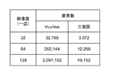
- Diagram for explaining the comparison of the number of elements of VoxNet with a three-view diagram 9 is a flowchart illustrating an example of an object recognition process performed by the object recognition device according to the second embodiment.
- FIG. 7 is a diagram for explaining an occupied grid according to the second embodiment.
- FIG. 14 is a diagram showing a hexahedral view of voxels in the occupied area of FIG.
- FIG. 1 is a diagram for describing an application example of the object recognition system 1 according to the present disclosure.
- the object recognition system 1 is applicable to, for example, in-vehicle applications.
- the object recognition system 1 is mounted on a vehicle 3.
- the vehicle 3 is, for example, an automatic driving vehicle, and includes a vehicle driving device 2 for performing automatic driving.
- the object recognition system 1 recognizes, for example, an object 4 in the traveling direction of the vehicle 3.
- the object 4 is, for example, a car, a bus, a motorcycle, a bicycle, a pedestrian, a utility pole, a curb, and a guardrail.
- the object recognition system 1 emits light toward the traveling direction of the vehicle 3 and receives the light reflected by the object 4.
- the object recognition system 1 measures a distance from the object recognition system 1 to the object 4 based on a time difference from light emission to light reception.
- the object recognition system 1 generates sensing data including a three-dimensional position along the outer shape of the object 4 based on the measured distance.
- the object recognition system 1 generates a plurality of two-dimensional information indicating a two-dimensional drawing in which a solid represented by a three-dimensional position is viewed from a plurality of directions, based on the sensing data.
- the object recognition system 1 recognizes an object based on a two-dimensional drawing viewed from a plurality of directions.
- the object recognition system 1 outputs, to the vehicle driving device 2, object information indicating, for example, the distance to the object 4, the azimuth, the recognition result, and the like.
- the vehicle drive device 2 includes, for example, a steering mechanism that drives the vehicle 3 by setting a traveling direction while avoiding the object 4 on the road based on the object information output from the object recognition system 1. By recognizing the object 4 by the object recognition system 1, the vehicle drive device 2 can perform automatic driving while avoiding the object 4.
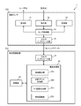
- FIG. 2 is a block diagram illustrating the configuration of the object recognition system 1.
- FIG. 3 is a diagram for explaining distance measurement by the distance sensor 100.
- the object recognition system 1 includes the distance sensor 100 and the object recognition device 200.
- the distance sensor 100 includes a light projecting unit 11, a light receiving unit 12, a scanning unit 13, a sensor control unit 14, and an input / output interface unit 15.
- the distance sensor 100 is, for example, a LIDAR (Light Detection and Ranging or Laser Imaging Detection and Ranging) device.
- LIDAR Light Detection and Ranging or Laser Imaging Detection and Ranging
- the light projecting unit 11 projects light to the outside. Specifically, the light projecting unit 11 emits a light beam to the outside under the control of the sensor control unit 14.
- the light projecting unit 11 includes, for example, a light source including one or more light source elements, and a light source driving circuit that drives the light source in a pulsed manner.
- the light source element is, for example, a semiconductor laser (LD) that emits laser light.
- the light source element may be an LED or the like.
- the light source elements are arranged, for example, in a row in the vertical direction Y shown in FIG. 3, and the light projecting unit 11 projects light toward the light projecting region R11.
- the light receiving unit 12 receives light from the outside.
- the light receiving section 12 includes a plurality of light receiving elements. When receiving light, the light receiving element generates a light receiving signal corresponding to the amount of received light.
- the plurality of light receiving elements are arranged, for example, in an array in a row along the vertical direction Y. Each light receiving element individually corresponds to, for example, one pixel of the distance image, and separately receives light incident from a range corresponding to the vertical angle of view of one pixel.
- the light receiving element is configured by, for example, a SPAD (single photon avalanche photodiode).
- the light receiving element may be constituted by a PD (photodiode) or an APD (avalanche photodiode).
- the scanning unit 13 includes, for example, a mirror, a rotation mechanism that rotates the mirror around a rotation axis along the vertical direction Y, and a scan drive circuit that drives the rotation mechanism.
- the scanning drive circuit rotates the mirror under the control of the sensor control unit 14. Accordingly, the scanning unit 13 gradually changes the light projection direction by gradually changing the light projecting direction at regular time intervals. For example, as shown in FIG. 3, the scanning unit 13 shifts the light projecting region R11 in the horizontal direction X.
- the sensor control unit 14 can be realized by a semiconductor element or the like.
- the sensor control unit 14 can be configured by, for example, a microcomputer, a CPU, an MPU, a GPU, a DSP, an FPGA, and an ASIC.
- the function of the sensor control unit 14 may be configured only by hardware, or may be realized by combining hardware and software.
- the sensor control unit 14 implements a predetermined function by reading data and programs stored in the storage unit in the distance sensor 100 and performing various arithmetic processing.
- the sensor control unit 14 controls the timing of light emission by the light emitting unit 11.
- the sensor control unit 14 generates, for each pixel, light-receiving waveform data indicating a light-receiving amount corresponding to an elapsed time after the light is projected, based on the light-emitting timing and the light-receiving signal obtained from the light-receiving unit 12.
- the sensor control unit 14 calculates a distance for each pixel based on the received light waveform. For example, the sensor control unit 14 measures the flight time of the light from when the light emitted from the light emitting unit 11 is reflected until the light is received by the light receiving unit 12 based on the light receiving waveform.
- the sensor control unit 14 calculates a distance from the reference point 5 to the outer shape of the object reflecting light based on the measured flight time.
- the reference point 5 is, for example, a light emission port of the light emitting unit 11.
- the sensor control unit 14 generates a distance image based on the distance measured for each pixel.
- the sensor control unit 14 measures the distance while scanning the projection plane R10 corresponding to the angle of view of the distance image in the horizontal direction X, and generates a distance image.
- the resolution of the range image that is, the angle of view for each pixel, is, for example, 1.0 to 1.6 degrees in the horizontal direction X and 0.3 to 1.2 degrees in the vertical direction Y.
- the sensor control unit 14 outputs the generated distance image as sensing data to the object recognition device 200 via the input / output interface unit 15, for example.
- the input / output interface unit 15 includes a circuit for communicating with an external device in accordance with a predetermined communication standard.
- the predetermined communication standard includes, for example, LAN, Wi-Fi (registered trademark), Bluetooth (registered trademark), USB, and HDMI (registered trademark).
- the object recognition device 200 is an information processing device such as a PC or various information terminals.
- the object recognition device 200 includes an input / output interface unit 21, an arithmetic processing unit 22, and a storage unit 23.
- the input / output interface unit 21 includes, for example, a device interface and a network interface.
- the device interface is a circuit (module) for connecting an external device such as the distance sensor 100 to the object recognition device 200.
- the device interface is an example of an acquisition unit that performs communication according to a predetermined communication standard.
- the predetermined standard includes USB, HDMI (registered trademark), IEEE 1395, Wi-Fi (registered trademark), Bluetooth (registered trademark), and the like.
- the network interface is a circuit (module) for connecting the object recognition device 200 to a communication network via a wireless or wired communication line.
- the network interface is an example of an acquisition unit that performs communication conforming to a predetermined communication standard.
- the predetermined communication standards include communication standards such as IEEE802.3 and IEEE802.11a / 11b / 11g / 11ac.
- the input / output interface unit 21 is an example of an input unit that inputs three-dimensional information including a three-dimensional position along at least a part of the outer shape of the object.
- the arithmetic processing unit 22 includes a CPU and a GPU that realize predetermined functions in cooperation with software, and controls the overall operation of the object recognition device 200.
- the arithmetic processing unit 22 reads out data and programs stored in the storage unit 23, performs various arithmetic processes, and realizes various functions.
- the function of the arithmetic processing unit 22 may be configured only by hardware, or may be realized by combining hardware and software.
- the arithmetic processing unit 22 executes a program for constructing a convolutional neural network described later.
- the program is stored in the storage unit 23.
- the program for constructing the convolutional neural network may be provided from various communication networks, or may be stored in a portable recording medium.
- the arithmetic processing unit 22 may be a hardware circuit such as a dedicated electronic circuit designed to realize a predetermined function or a reconfigurable electronic circuit.
- the arithmetic processing unit 22 may be configured by various semiconductor integrated circuits such as an MPU, a GPGPU, a TPU, a microcomputer, a DSP, an FPGA, and an ASIC, in addition to the CPU and the GPU.
- the arithmetic processing unit 22 includes, as functional components, an area detection unit 22a, an occupied grid generation unit 22b, a 2D drawing generation unit 22c, and an object recognition unit 22d.
- the area detection unit 22a detects an area where one object exists in the distance image as an object recognition target area.
- the occupied grid generation unit 22b generates occupied grid data indicating an occupied grid in which the detected object in the recognition target area is represented by a set of voxels.
- the 2D drawing generation unit 22c generates a two-dimensional drawing of the voxel aggregate based on the occupation grid data. In the present embodiment, the 2D drawing generation unit 22c generates a three-view drawing.
- the three-view drawing is an example of a plurality of two-dimensional information.
- the object recognition unit 22d recognizes the type of the object by executing image processing using a convolutional neural network based on the three views.
- the storage unit 23 stores parameters, data, control programs, and the like necessary to realize a predetermined function.
- the storage unit 23 stores a program for a convolutional neural network, parameters during and after learning, and the like.
- the storage unit 23 can be realized by, for example, a hard disk (HDD), SSD, RAM, DRAM, SRAM, ferroelectric memory, flash memory, magnetic disk, or a combination thereof.
- the storage unit 23 may temporarily store various information.
- the storage unit 23 may be configured to function as a work area of the arithmetic processing unit 22, for example.
- the object recognition device 200 may include an operation unit that is a user interface for a user to operate.
- the operation unit includes, for example, a keyboard, a touchpad, a touch panel, buttons, switches, and a combination thereof.
- the object recognition device 200 may include a display unit including a liquid crystal display or an organic EL display.
- the object recognition device 200 may include a speaker that outputs sound.
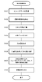
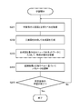
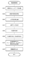
- FIG. 4 is a flowchart illustrating the operation of the arithmetic processing unit 22 of the object recognition device 200.
- the area detection unit 22a acquires the sensing data generated by the distance sensor 100 via the input / output interface unit 21 (S101).
- the sensing data is a distance image indicating a distance from the reference point 5 to the outer shape of the object.
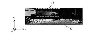
- FIG. 5 shows an example of the distance image 30.
- the distance image 30 indicates the distance in the depth direction Z for each pixel arranged in the horizontal direction X and the vertical direction Y. That is, in the distance image 30, each pixel has a pixel value indicating a distance in the depth direction Z.
- the distance in the depth direction Z is identified by the color of each pixel.
- the distance image 30 is an example of three-dimensional information including a three-dimensional position along at least a part of the outer shape of the object.
- the area detection unit 22a detects an area where one object exists as a recognition target area based on the sensing data (S102).
- the detection of the recognition target area can be performed using a known technique. For example, when the difference between the pixel value of each pixel and the pixel values of the eight surrounding pixels in the distance image 30 is equal to or less than a predetermined threshold, the region detection unit 22a determines that the objects are the same object and determines the recognition target region 35. To detect.
- the occupancy grid generation unit 22b defines a three-dimensional space of a predetermined size (S103).
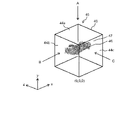
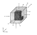
- FIG. 6 schematically shows the three-dimensional space 40.
- the occupancy grid generation unit 22b defines, for example, a cubic three-dimensional space 40 composed of 32 ⁇ 32 ⁇ 32 voxels 41 in a virtual coordinate system (x, y, z).
- the occupancy grid generation unit 22b generates occupancy grid data indicating the occupancy grid based on the detected recognition target area 35 and the defined three-dimensional space 40 (S104).
- FIG. 7 schematically shows an example of the occupation grid 45.
- the occupancy grid 45 is an aggregate of the voxels 41 in which the occupation area 46 and the non-occupation area 47 are distinguished in the three-dimensional space 40.
- the occupied area 46 indicates an area where an object exists, and the non-occupied area 47 indicates an area where no object exists.
- the occupancy grid generation unit 22b performs, for example, coordinate conversion on the coordinate system in the distance image 30 and associates each pixel in the recognition target area 35 with the voxel 41 in the three-dimensional space 40.
- the occupancy grid generation unit 22b determines which voxel 41 in the three-dimensional space corresponds to each pixel indicating the distance value in the recognition target area 35, and assigns a flag to each voxel 41, thereby occupying each voxel 41.
- the occupancy grid data indicating the grid 45 is generated.
- the flag is, for example, a binary value indicating whether or not the object is an object.
- the three-dimensional body constituted by the voxels 41 in the occupation area 46 corresponds to at least a part of the object.
- the 2D drawing generation unit 22c generates a three-dimensional view of the solid constituted by the voxels 41 in the occupied area 46 (S105). For example, the 2D drawing generation unit 22c generates a two-dimensional drawing in which the voxel 41 in the occupied area 46 is viewed from directions A, B, and C in FIG.
- FIG. 8A is a plan view 50A viewed from the direction A.
- FIG. 8B is a front view 50B viewed from the direction B.
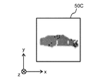
- FIG. 8C is a side view 50C viewed from the direction C.
- the plan view 50A, the front view 50B, and the side view 50C are collectively referred to as three views 50A, 50B, and 50C. In the directions A, B, and C shown in FIG.
- the 2D drawing generation unit 22c generates pixels corresponding to the distances from the planes 44a, 44b, and 44c that form the cube of the three-dimensional space 40 to each voxel in the occupied area 46.
- the three views 50A, 50B, and 50C have pixel values represented by any of RGB, for example. In one example, the top view 50A is red, the front view 50B is green, and the side view 50C is blue.
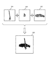
- the 2D drawing generation unit 22c combines the three views 50A, 50B, and 50C to generate one combined drawing (S106).
- FIG. 9 shows an example of a composite diagram 50D generated from the three views 50A, 50B, and 50C.
- the 2D drawing generation unit 22c determines the pixel value of each pixel in the composite drawing 50 based on the pixel value of each pixel in the three views 50A, 50B, and 50C.
- the color of each pixel in the composite view 50 is a color based on red, green, and blue in the plan view 50A, the front view 50B, and the side view 50C.
- the object recognition unit 22d inputs the composite diagram 50D to the learned convolutional neural network and recognizes the type of the object (S107).
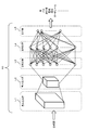
- FIG. 10 is a diagram for explaining image processing by the convolutional neural network 60.
- the convolutional neural network 60 has been learned in advance so as to recognize an object using a composite diagram showing an object such as a car, a bus, a pedestrian, a telephone pole, and a curbstone.
- the learning method of the convolutional neural network 60 will be described later.
- the programs and parameters for constructing the learned convolutional neural network 60 are stored in the storage unit 23, for example.
- the object recognition unit 22d calculates the probability of being a car, a bus, a pedestrian, a telephone pole, a curb, a guardrail, or the like from the composite diagram 50D by executing image processing using the convolutional neural network 60.
- the convolutional neural network 60 includes, for example, in order from the input side to the output side, convolutional layers L1 and L2, fully connected layers L3 and L4, and an output layer L5.
- the number of convolutional layers L1 and L2 and the number of all connection layers L3 and L4 are each two, but the number of layers is not limited to two. Further, a pooling layer may be provided after the convolution layers L1 and L2.
- the composite diagram 50D is input to the first convolution layer L1.
- a convolution operation using each filter is performed.
- the filters of the convolution layers L1 and L2 are defined by a two-dimensional array of weighting coefficients.
- the output layer L5 outputs an object recognition result. For example, a vector indicating the probability that the object is a car, a bus, a pedestrian, a utility pole, a curb, a guardrail, or the like is output.
- the object recognition unit 22d outputs a recognition result (S108). For example, the object recognizing unit 22d specifies that the object having the highest probability among the probabilities output from the output layer L5 is the object shown in the composite diagram 50D, and specifies the object via the input / output interface unit 21.
- the object information indicating the type of the object is output to the vehicle drive device 2.
- the object recognition device 200 includes a display unit
- the type of the object as the recognition result may be displayed on a screen of the display unit.
- the type of the object as the recognition result may be output as voice from the speaker.
- FIG. 11 shows a learning process of the convolutional neural network 60.
- the arithmetic processing unit 22 performs the learning processing illustrated in FIG. 11 to cause the convolutional neural network 60 to learn.
- the arithmetic processing unit 22 acquires the learning three-view drawing and data indicating the correct answer label corresponding to the three-view drawing (S201). For example, the arithmetic processing unit 22 acquires the learning data indicating the three-view drawing and the correct answer label corresponding to the three-view drawing via the input / output interface unit 21 and stores the learning data in the storage unit 23 in advance. In step S201, the arithmetic processing unit 22 reads the learning data from the storage unit 23. Correct labels are, for example, cars, buses, pedestrians, utility poles, curbs, and guardrails.
- the arithmetic processing unit 22 combines the three views to generate a combined view (S202).
- the arithmetic processing unit 22 inputs the composite diagram to the convolutional neural network 60 and recognizes the type of the object (S203).
- the operation processing unit 22 adjusts the parameters of the convolutional neural network 60 based on the recognition result and the correct answer label (S204). For example, the arithmetic processing unit 22 adjusts the weighting coefficients of the filters of the convolution layers L1 and L2 and the weighting coefficients between the neurons of the fully connected layers L3 and L4 according to the backpropagation method.
- the arithmetic processing unit 22 determines whether learning for a predetermined number of times has been completed (S205). Steps S201 to S204 are repeated until learning for a predetermined number of times is completed. When the learning for the predetermined number of times is completed, the learning process shown in FIG. 11 is completed.
- the arithmetic processing unit 22 stores a program and parameters corresponding to the learned convolutional neural network 60 in the storage unit 23.
- step S201 a three-view drawing is obtained in step S201 and a composite drawing is generated in step S202.
- a composite drawing may be obtained in step S201.
- step S202 is omitted.
- FIG. 12 is a diagram comparing the number of elements used for object recognition, and shows the number of elements (the number of voxels) in the conventional VoxNet and the three-sided view of the present disclosure. Indicates the number of elements (the number of pixels) in.
- the number of elements on one side is 32
- the number of elements on one side is 64
- the number of voxels on one side is 128, the number of elements of VoxNet is 2097152, and is 49152 in the three views. Therefore, the number of elements in the three views is about 1/40 of the number of elements of VoxNet.
- the processing load of the two-dimensional CNN using the three-view drawing image is smaller than that of the three-dimensional CNN. Therefore, the processing speed of object recognition is improved.
- the occupation area 46 does not correspond to the entire object. Therefore, even if the occupation grid 45 is converted into a three-view drawing, the information amount of the distance value of the object is not significantly reduced, and the object can be recognized with high accuracy.
- the object recognition system 1 includes a distance sensor 100 and an object recognition device 200.
- the distance sensor 100 measures a distance to the object and generates sensing data including a three-dimensional position along at least a part of the outer shape of the object.
- the object recognition device 200 includes an input / output interface unit 21 and an arithmetic processing unit 22.
- the input / output interface unit 21 inputs sensing data.
- the arithmetic processing unit 22 recognizes an object based on the sensing data.
- the arithmetic processing unit 22 generates a plurality of two-dimensional drawings in which a solid represented by a three-dimensional position is viewed from a plurality of directions based on the sensing data, and generates an object based on the plurality of two-dimensional drawings. Recognize.
- the arithmetic processing unit 22 recognizes an object by performing image processing by the convolutional neural network 60 based on the generated two-dimensional drawings.
- the two-dimensional convolutional neural network can reduce the size of the network as compared with the three-dimensional convolutional neural network. For example, the number of layers and the number of neurons can be reduced.
- the sensing data is a distance image indicating a distance from the reference point 5 to the outer shape of the object.
- the arithmetic processing unit 22 generates an aggregate of voxels representing a solid based on the distance image. Specifically, the arithmetic processing unit 22 defines a three-dimensional space 40 that can be divided into a plurality of voxels, associates a three-dimensional position along the outer shape of the object with the three-dimensional space, and Represents a solid by the voxels occupied by. This solid corresponds to the voxel of the occupied area 46.
- the sensing data includes a three-dimensional position along the external shape of a part of the object, and the plurality of two-dimensional drawings are three-dimensional views of the solid viewed from three orthogonal axes.
- the three views have pixel values according to the distance from the planes 44a, 44b, and 44c, which are the respective reference positions, to the solid.
- the arithmetic processing unit 22 combines the three views to generate a combined diagram, and recognizes an object based on the combined diagram. Since the three-view drawing has approximately the same amount of information on distance as three-dimensional information, object recognition using the three-view drawing can obtain the same level of accuracy as object recognition using three-dimensional voxels.
- the object recognition device 200 performs the object recognition using the three-view drawing generated based on the distance measurement in the projection plane R10 by one distance sensor 100.
- object recognition is performed using a hexahedral view.
- the hexagonal view is an example of a plurality of two-dimensional information.
- FIG. 13 is a flowchart illustrating an example of an object recognition process performed by the object recognition device 200 according to the second embodiment. Steps S302 to S304, S307, and S308 in FIG. 13 are the same as steps S102 to S104, S107, and S108 in FIG. 4 of the first embodiment.
- the area detection unit 22a acquires a plurality of pieces of sensing data via the input / output interface unit 21 (S301).
- Each of the sensing data includes a three-dimensional position along a part of the outer shape of the object, and the plurality of sensing data includes a three-dimensional position along the entire outer shape of the object.
- the plurality of sensing data are, for example, distance images generated based on distance measurement from the plurality of reference points 5.
- the plurality of reference points 5 are provided, for example, at opposing positions.
- the area detection unit 22a acquires sensing data from a plurality of distance sensors arranged at different positions.
- the area detection unit 22a may acquire a plurality of pieces of sensing data generated by one distance sensor measuring distances at different positions.
- the area detection unit 22a detects an area where an object exists in each of the distance images as a recognition target area (S302).
- the occupancy grid generation unit 22b defines the three-dimensional space 40 (S303).
- the occupancy grid generation unit 22b converts the local coordinates of each recognition target area into world coordinates and generates occupancy grid data indicating one occupancy grid 45 (S304).
- FIG. 14 is a diagram for explaining the occupation grid 45 in the second embodiment.
- the occupation grid 45 is an aggregate of the voxels 41 in which the occupied area 46 and the non-occupied area 47 are distinguished in the three-dimensional space 40 as in the first embodiment.
- FIG. 15 is a six-view drawing in which the voxels 41 in the occupied area 46 are viewed from the directions of arrows a to f in FIG.
- FIG. 15A is a front view as viewed from the direction of arrow a in FIG.
- FIG. 15B is a rear view as viewed from the direction of arrow b in FIG.
- FIG. 15C is a left side view as seen from the direction of arrow c in FIG.
- FIG. 15D is a right side view as seen from the direction of arrow d in FIG.
- FIG. 15 is a six-view drawing in which the voxels 41 in the occupied area 46 are viewed from the directions of arrows a to f in FIG.
- FIG. 15A is a front view as viewed from the direction of arrow a in FIG.
- FIG. 15B is a rear view as viewed from the direction of arrow b in FIG.
- FIG. 15C is a left side view as seen from the direction of
- FIGS. 15E is a plan view (top view) viewed from the direction of arrow e in FIG.
- FIG. 15F is a bottom view as seen from the direction of arrow f in FIG.
- the six views shown in FIGS. 15A to 15F have pixel values corresponding to the distance from each plane of the cube showing the three-dimensional space 40 to each voxel of the occupied area 46.
- the color may be darker as the distance is shorter, and lighter as the distance is longer.
- FIGS. 15A to 15F pixels where no object exists are shown in white, but may be shown in black.
- the 2D drawing generation unit 22c combines the six views to generate one combined drawing (S306).
- the object recognition unit 22d inputs the synthesized diagram to the learned convolutional neural network 60, and recognizes the type of the object (S307).
- the object recognition unit 22d outputs a recognition result (S308).
- the plurality of pieces of sensing data include three-dimensional positions along the entire outer shape of the object.
- the object recognition device 200 generates a hexahedral view in which the solid formed by the voxels in the occupied area 46 is viewed from three orthogonal orthogonal directions.
- the object recognition device 200 recognizes an object using a hexahedral view. This makes it possible to perform object recognition based on the entire outer shape of the object. Therefore, the object can be recognized with high accuracy.
- the sensing data is a distance image
- the object recognition device 200 generates the occupation grid 45 based on the distance image.
- the sensing data is not limited to the distance image.
- the sensing data may include a three-dimensional position along at least a part of the outer shape of the object.
- the sensing data may be three-dimensional point group information indicating the distance to the outer shape of the object measured by the distance sensor 100.
- Such three-dimensional point group information includes, for example, an x coordinate, a y coordinate, and a z coordinate.
- the 2D drawing generation unit 22c generates a three-dimensional drawing or a six-dimensional drawing of a solid formed by the voxels 41 in the occupied area 46. However, if the number of generated two-dimensional drawings is two or more, Good.
- the arithmetic processing unit 22 of the object recognition device 200 performs the learning process illustrated in FIG. 11 .
- the learning process of the convolutional neural network 60 is performed by a device different from the object recognition device 200. You may.
- the convolutional neural network 60 may be constructed by a computer cluster or cloud computing.
- the distance sensor 100 and the object recognition device 200 are mounted on the vehicle 3 .
- the distance sensor 100 and the object recognition device 200 are not limited to the vehicle 3 but may be mounted on a self-propelled robot or an AGV (Automated Guided Vehicle).
- the object recognition device 200 may not be mounted on the vehicle 3 or the like.
- the object recognition device 200 according to the present disclosure may be various information processing devices.
- the object recognition device 200 may be one or more server devices such as an ASP server.
- the object recognition device 200 may acquire sensing data from the distance sensor 100 via a communication network, and execute image processing using the convolutional neural network 60. Further, the object recognition device 200 may transmit information indicating the result of object recognition to the vehicle drive device 2 via a communication network.
- the distance sensor 100 and the object recognition device 200 are separate devices, but the distance sensor 100 and the object recognition device 200 may be one device.
- the object recognition device 200 may be provided inside the distance sensor 100, and the distance sensor 100 may have the same function as the object recognition device 200.
- the recognition operation is not limited to identifying the type of the object.
- Recognition includes extracting a feature amount of an object. For example, when the target object is a car, the recognition performed by the object recognizing unit 22d includes extracting “rectangular solid” and “wheel” as the feature amounts of the car.
- An object recognition device includes an input unit (21) for inputting three-dimensional information including a three-dimensional position along at least a part of an outer shape of an object, and the input unit (21) based on the three-dimensional information.
- An arithmetic processing unit (22) for recognizing an object wherein the arithmetic processing unit (22) is configured to perform two-dimensional viewing of a solid represented by the three-dimensional position from a plurality of directions based on the three-dimensional information.
- a plurality of two-dimensional information items showing a drawing are generated, and the object is recognized based on the plurality of two-dimensional information items.
- the arithmetic processing unit recognizes the object by executing image processing using a convolutional neural network based on the generated plurality of two-dimensional information.
- the three-dimensional information is a distance image indicating a distance from a reference point to at least a part of the outer shape of the object.
- the arithmetic processing unit generates an aggregate of voxels representing the solid based on the three-dimensional information.
- the arithmetic processing unit defines a three-dimensional space that can be divided into a plurality of voxels, and associates the three-dimensional position with the three-dimensional space, The solid is represented by voxels occupied by the object among the plurality of voxels.
- the plurality of two-dimensional information has a pixel value according to a distance from each reference position to the solid.
- the three-dimensional information includes a three-dimensional position along an outer shape of a part of the object;
- the dimensional information is a three-view drawing of the solid as viewed from each of three orthogonal directions.
- the three-dimensional information includes a three-dimensional position along an entire outer shape of the object, and the plurality of two-dimensional information FIG. 6 is a six-view drawing of the solid viewed from each of three orthogonal axes in the positive and negative directions.
- the arithmetic processing unit generates a composite diagram by synthesizing the plurality of two-dimensional information, and generates the composite diagram. The object is recognized based on the object.
- the object recognition system is a sensor that measures the distance to an object to generate the three-dimensional information, and the object recognition device according to any one of the first to ninth aspects, including.
- a program includes a step of inputting three-dimensional information including a three-dimensional position along at least a part of an outer shape of an object; and a step of inputting a plurality of solids represented by the three-dimensional position based on the three-dimensional information. And causing the computer to execute a step of generating a plurality of two-dimensional information indicating a two-dimensional drawing viewed from the direction of and a step of recognizing the object based on the plurality of two-dimensional information.
- the object recognition device and the object recognition system of the present disclosure are applicable to, for example, an automatic driving vehicle, a self-propelled robot, an AGV, and the like.
Landscapes
- Engineering & Computer Science (AREA)
- Computer Vision & Pattern Recognition (AREA)
- Physics & Mathematics (AREA)
- General Physics & Mathematics (AREA)
- Theoretical Computer Science (AREA)
- Image Analysis (AREA)
Abstract
物体認識装置(200)は、物体の少なくとも一部の外形に沿った三次元位置を含む三次元情報を入力する入力部(21)と、三次元情報に基づいて物体を認識する演算処理部(22)と、を備え、演算処理部(22)は、三次元情報に基づいて、三次元位置によって表される立体を複数の方向から見た複数の二次元情報を生成し、複数の二次元情報に基づいて物体を認識する。
Description
本開示は、物体を認識する物体認識装置、物体認識システム、及びプログラムに関する。
非特許文献1は、VoxNetを開示している。VoxNetは、三次元畳み込みニューラルネットワーク(3D CNN)を使用した画像処理によって物体を認識する手法である。具体的には、VoxNetは、LiDAR及びRGBDセンサ等から得られる三次元点群データを、所定サイズの三次元空間に写像して三次元情報を生成し、その三次元情報を三次元畳み込みニューラルネットワークに入力して物体を認識する手法である。
Daniel Maturana, Sebastian Scherer, "VoxNet: A 3D Convolutional Neural Network for Real-Time Object Recognition", インターネット<URL:https://www.ri.cmu.edu/pub_files/2015/9/voxnet_maturana_scherer_iros15.pdf>
非特許文献1のような三次元畳み込みニューラルネットワークによる画像処理では、データ量が多く且つ大きなネットワークが必要であった。そのため、画像処理の処理負荷が大きく、物体認識の処理速度が遅かった。
本開示の目的は、画像処理の処理負荷を低減して、物体認識の処理速度を向上させる、物体認識装置、物体認識システム、及びプログラムを提供することにある。
本開示に係る物体認識装置は、物体の少なくとも一部の外形に沿った三次元位置を含む三次元情報を入力する入力部と、三次元情報に基づいて物体を認識する演算処理部と、を備え、演算処理部は、三次元情報に基づいて、三次元位置によって表される立体を複数の方向から見た二次元図面を示す複数の二次元情報を生成し、複数の二次元情報に基づいて物体を認識する。
本開示に係る物体認識システムは、物体までの距離を計測して三次元情報を生成するセンサと、上記物体認識装置と、を含む。
本開示に係るプログラムは、物体の少なくとも一部の外形に沿った三次元位置を含む三次元情報を入力するステップと、三次元情報に基づいて、三次元位置によって表される立体を複数の方向から見た二次元図面を示す複数の二次元情報を生成するステップと、複数の二次元情報に基づいて物体を認識するステップと、をコンピュータに実行させる。
本開示に係る物体認識装置、物体認識システム、及びプログラムによると、物体の少なくとも一部の外形に沿った三次元位置によって表される立体を複数の方向から見た二次元図面を示す複数の二次元情報に基づいて物体を認識するため、画像処理の処理負荷が低減する。よって、物体認識の処理速度が向上する。
以下、添付の図面を参照して本開示に係る物体認識システムの実施の形態を説明する。なお、以下の各実施形態において、同様の構成要素については同一の符号を付している。
(適用例)
本開示に係る物体認識システムが適用可能な一例について、図1を用いて説明する。図1は、本開示に係る物体認識システム1の適用例を説明するための図である。
本開示に係る物体認識システムが適用可能な一例について、図1を用いて説明する。図1は、本開示に係る物体認識システム1の適用例を説明するための図である。
本開示に係る物体認識システム1は、例えば、車載用途に適用可能である。図1に示す例において、物体認識システム1は車両3に搭載される。車両3は、例えば、自動運転車であり、自動運転を行うための車両駆動装置2を備える。物体認識システム1は、例えば、車両3の進行方向にある物体4を認識する。物体4は、例えば、車、バス、バイク、自転車、歩行者、電柱、縁石、ガードレールである。
物体認識システム1は、車両3の進行方向に向けて光を投光し、物体4によって反射された反射光を受光する。物体認識システム1は、投光から受光までの時間差に基づいて、物体認識システム1から物体4までの距離を計測する。物体認識システム1は、計測した距離に基づいて、物体4の外形に沿った三次元位置を含むセンシングデータを生成する。
物体認識システム1は、センシングデータに基づいて、三次元位置によって表される立体を複数の方向から見た二次元図面を示す複数の二次元情報を生成する。物体認識システム1は、複数の方向から見た二次元図面に基づいて物体を認識する。物体認識システム1は、例えば、物体4までの距離、方位、及び認識結果などを示す物体情報を車両駆動装置2に出力する。
車両駆動装置2は、例えば、物体認識システム1から出力される物体情報に基づいて、道路上の物体4を回避して進行方向を設定して、車両3を駆動する操舵機構を含む。物体認識システム1によって物体4を認識することによって、車両駆動装置2は、物体4を回避しながら自動運転を行うことができる。
(構成例)
以下、物体認識システム1の構成例としての実施形態を説明する。
以下、物体認識システム1の構成例としての実施形態を説明する。
(実施形態1)
実施形態1に係る物体認識システム1の構成と動作を以下に説明する。
実施形態1に係る物体認識システム1の構成と動作を以下に説明する。
1.構成
本実施形態に係る物体認識システム1の構成について、図2及び図3を用いて説明する。図2は、物体認識システム1の構成を例示するブロック図である。図3は、距離センサ100による測距を説明するための図である。
本実施形態に係る物体認識システム1の構成について、図2及び図3を用いて説明する。図2は、物体認識システム1の構成を例示するブロック図である。図3は、距離センサ100による測距を説明するための図である。
物体認識システム1は、距離センサ100と物体認識装置200とを含む。
1.1 距離センサの構成
距離センサ100は、投光部11、受光部12、走査部13、センサ制御部14、及び入出力インタフェース部15を含む。距離センサ100は、例えば、LIDAR(Light Detection and Ranging、あるいは、Laser Imaging Detection and Ranging)装置である。
距離センサ100は、投光部11、受光部12、走査部13、センサ制御部14、及び入出力インタフェース部15を含む。距離センサ100は、例えば、LIDAR(Light Detection and Ranging、あるいは、Laser Imaging Detection and Ranging)装置である。
投光部11は、光を外部に投光する。具体的には、投光部11は、センサ制御部14の制御に従って、光の光束を外部に出射する。投光部11は、例えば、1つ以上の光源素子で構成された光源と、光源をパルス駆動する光源駆動回路とを含む。光源素子は、例えば、レーザ光を発光する半導体レーザ(LD)である。光源素子は、LED等であってもよい。光源素子は、例えば、図3に示す垂直方向Yにおいて一列のアレイ状に配置され、投光部11は投光領域R11に向けて光を投光する。
受光部12は、外部から光を受光する。受光部12は、複数の受光素子を備える。受光素子は、光を受光すると、受光量に応じた受光信号を生成する。複数の受光素子は、例えば、垂直方向Yに沿って一列のアレイ状に配置される。各受光素子は、例えば距離画像の1画素に対応し、1画素の垂直画角に応じた範囲から入射する光を別々に受光する。受光素子は、例えばSPAD(単一光子アバランシェフォトダイオード)で構成される。受光素子は、PD(フォトダイオード)又はAPD(アバランシェフォトダイオード)で構成されてもよい。
走査部13は、例えば、ミラーと、垂直方向Yに沿った回転軸の周りにミラーを回転させる回転機構と、回転機構を駆動する走査駆動回路と、を含む。走査駆動回路は、センサ制御部14の制御により、ミラーを回転駆動する。これにより、走査部13は、投光する方向を一定時間ごとに少しずつ変化させて、光が進行する光路を少しずつ移動させる。例えば、図3に示すように、走査部13は、投光領域R11を水平方向Xにおいてシフトさせる。
センサ制御部14は、半導体素子などで実現可能である。センサ制御部14は、例えば、マイコン、CPU、MPU、GPU、DSP、FPGA、ASICで構成することができる。センサ制御部14の機能は、ハードウェアのみで構成してもよいし、ハードウェアとソフトウェアとを組み合わせることにより実現してもよい。センサ制御部14は、距離センサ100内の記憶部に格納されたデータやプログラムを読み出して種々の演算処理を行うことで、所定の機能を実現する。
センサ制御部14は、投光部11による投光のタイミングを制御する。センサ制御部14は、投光のタイミングと受光部12から得られる受光信号とに基づいて、投光してからの経過時間に応じた受光量を示す受光波形のデータを画素毎に生成する。センサ制御部14は、受光波形に基づいて画素毎に距離を算出する。例えば、センサ制御部14は、投光部11から投光された光が反射されて受光部12によって受光されるまでの光の飛行時間を受光波形に基づいて計測する。センサ制御部14は、計測した飛行時間に基づいて、基準点5から光を反射した物体の外形までの距離を算出する。基準点5は、例えば、投光部11の光の出射口である。センサ制御部14は、画素毎に測定した距離に基づいて、距離画像を生成する。
センサ制御部14は、距離画像の画角に対応した投影面R10を、水平方向Xに走査しながら測距を行い、距離画像を生成する。距離画像の分解能すなわち画素毎の画角は、例えば、水平方向Xにおいて1.0度~1.6度であり、垂直方向Yにおいて0.3度~1.2度である。投影面R10の走査を繰り返すことにより、所望のフレームレートで距離画像を順次、生成することができる。センサ制御部14は、例えば、生成した距離画像をセンシングデータとして、入出力インタフェース部15を介して、物体認識装置200に出力する。
入出力インタフェース部15は、所定の通信規格に準拠して外部機器との通信を行う回路を含む。所定の通信規格は、例えば、LAN、Wi-Fi(登録商標)、Bluetooth(登録商標)、USB、及びHDMI(登録商標)を含む。
1.2 物体認識装置の構成
物体認識装置200は、例えばPCや種々の情報端末などの情報処理装置である。物体認識装置200は、入出力インタフェース部21、演算処理部22、及び記憶部23を備える。
物体認識装置200は、例えばPCや種々の情報端末などの情報処理装置である。物体認識装置200は、入出力インタフェース部21、演算処理部22、及び記憶部23を備える。
入出力インタフェース部21は、例えば、機器インタフェースとネットワークインタフェースを含む。機器インタフェースは、物体認識装置200に、距離センサ100等の外部機器を接続するための回路(モジュール)である。機器インタフェースは、所定の通信規格にしたがい通信を行う取得部の一例である。所定の規格には、USB、HDMI(登録商標)、IEEE1395、Wi-Fi(登録商標)、Bluetooth(登録商標)等が含まれる。ネットワークインタフェースは、無線または有線の通信回線を介して物体認識装置200を通信ネットワークに接続するための回路(モジュール)である。ネットワークインタフェースは所定の通信規格に準拠した通信を行う取得部の一例である。所定の通信規格には、IEEE802.3,IEEE802.11a/11b/11g/11ac等の通信規格が含まれる。入出力インタフェース部21は、物体の少なくとも一部の外形に沿った三次元位置を含む三次元情報を入力する入力部の一例である。
演算処理部22は、ソフトウェアと協働して所定の機能を実現するCPUやGPUを含み、物体認識装置200の全体動作を制御する。演算処理部22は、記憶部23に格納されたデータやプログラムを読み出して種々の演算処理を行い、各種の機能を実現する。演算処理部22の機能は、ハードウェアのみで構成してもよいし、ハードウェアとソフトウェアとを組み合わせることにより実現してもよい。演算処理部22は、後述する畳み込みニューラルネットワークを構築するプログラムを実行する。プログラムは、記憶部23に格納されている。畳み込みニューラルネットワークを構築するプログラムは、各種の通信ネットワークから提供されてもよいし、又は可搬性を有する記録媒体に格納されていてもよい。
演算処理部22は、所定の機能を実現するように設計された専用の電子回路や再構成可能な電子回路などのハードウェア回路であってもよい。演算処理部22は、CPU、GPUの他に、MPU、GPGPU、TPU、マイコン、DSP、FPGA、ASIC等の種々の半導体集積回路で構成されてもよい。
演算処理部22は、機能的構成として、領域検出部22a、占有グリッド生成部22b、2D図面生成部22c、及び物体認識部22dを含む。領域検出部22aは、距離画像において1つの物体が存在する領域を、物体の認識対象領域として検出する。占有グリッド生成部22bは、検出された認識対象領域内の物体をボクセルの集合体によって表した占有グリッドを示す占有グリッドデータを生成する。2D図面生成部22cは、占有グリッドデータに基づいて、ボクセル集合体の二次元図面を生成する。本実施形態においては、2D図面生成部22cは、三面図を生成する。三面図は、複数の二次元情報の一例である。物体認識部22dは、三面図に基づき畳み込みニューラルネットワークによる画像処理を実行して、物体の種別を認識する。
記憶部23は、所定の機能を実現するために必要なパラメータ、データ及び制御プログラム等を格納する。例えば、記憶部23は、畳み込みニューラルネットワークのためのプログラム、学習中及び学習済みのパラメータなどを格納する。記憶部23は、例えば、ハードディスク(HDD)、SSD、RAM、DRAM、SRAM、強誘電体メモリ、フラッシュメモリ、磁気ディスク、又はこれらの組み合わせによって実現できる。記憶部23は、各種情報を一時的に記憶してもよい。記憶部23は、例えば、演算処理部22の作業エリアとして機能するように構成されてもよい。
物体認識装置200は、ユーザが操作を行うユーザインタフェースである操作部を備えてもよい。操作部は、例えば、キーボード、タッチパッド、タッチパネル、ボタン、スイッチ、及びこれらの組み合わせで構成される。物体認識装置200は、液晶ディスプレイや有機ELディスプレイで構成される表示部を備えてもよい。物体認識装置200は、音声を出力するスピーカを備えてもよい。
2.動作
2.1 物体認識処理
以上のように構成される物体認識システム1の物体認識処理に関する動作について、図4~図10を参照して説明する。
2.1 物体認識処理
以上のように構成される物体認識システム1の物体認識処理に関する動作について、図4~図10を参照して説明する。
図4は、物体認識装置200の演算処理部22の動作を例示するフローチャートである。
領域検出部22aは、距離センサ100が生成したセンシングデータを、入出力インタフェース部21を介して取得する(S101)。本実施形態において、センシングデータは、基準点5から物体の外形までの距離を示す距離画像である。図5に、距離画像30の一例を示している。距離画像30は、水平方向X及び垂直方向Yに並んだ画素毎に、奥行き方向Zの距離を示す。すなわち、距離画像30において、各画素は、奥行き方向Zの距離を示す画素値を有する。距離画像30において、例えば、奥行き方向Zの距離は各画素の色によって識別される。一例では、距離が近いほど赤色になり(例えば、画素値がRGB=(255,0,0)に近づき)、距離が遠いほど青色になる(例えば、画素値がRGB=(0,0,255)に近づく)。距離画像30は、物体の少なくとも一部の外形に沿った三次元位置を含む三次元情報の一例である。
領域検出部22aは、センシングデータに基づいて、1つの物体が存在する領域を認識対象領域として検出する(S102)。認識対象領域の検出は、公知の技術を用いて行うことができる。例えば、領域検出部22aは、距離画像30において、各画素の画素値と周囲8画素の画素値との差が所定の閾値以下の場合に同一の物体である判断して、認識対象領域35を検出する。
占有グリッド生成部22bは、所定サイズの三次元空間を定義する(S103)。図6は、三次元空間40を模式的に示している。占有グリッド生成部22bは、例えば、仮想的な座標系(x,y,z)において32×32×32個のボクセル41で構成される立方体の三次元空間40を定義する。
占有グリッド生成部22bは、検出した認識対象領域35と定義した三次元空間40とに基づいて、占有グリッドを示す占有グリッドデータを生成する(S104)。図7は、占有グリッド45の一例を模式的に示している。占有グリッド45は、三次元空間40内において占有領域46と非占有領域47とが区別された、ボクセル41の集合体である。占有領域46は物体が存在する領域を示し、非占有領域47は物体が存在しない領域を示す。占有グリッド生成部22bは、例えば、距離画像30における座標系を座標変換して、認識対象領域35内の各画素を三次元空間40のボクセル41に対応付ける。占有グリッド生成部22bは、認識対象領域35内の距離値を示す各画素が三次元空間40のいずれのボクセル41に対応するかを判断して、各ボクセル41にフラグを付与することによって、占有グリッド45を示す占有グリッドデータを生成する。フラグは、例えば、物体であるか否かを示す二値である。占有領域46内のボクセル41で構成される立体が、物体の少なくとも一部分に相当する。
2D図面生成部22cは、占有領域46内のボクセル41で構成される立体の三面図を生成する(S105)。例えば、2D図面生成部22cは、図7において、占有領域46内のボクセル41を方向A,B,Cから見た二次元図面を生成する。図8Aは、方向Aから見た平面図50Aである。図8Bは、方向Bから見た正面図50Bである。図8Cは、方向Cから見た側面図50Cである。平面図50A、正面図50B、及び側面図50Cをまとめて三面図50A,50B,50Cとも称する。2D図面生成部22cは、図7に示す方向A,B,Cにおいて、三次元空間40の立方体を構成する平面44a,44b,44cから、占有領域46内の各ボクセルまでの距離に応じた画素値を有する三面図50A,50B,50Cを生成する。図8A~図8Cの例では、距離が近いほど淡い色になり(例えば、画素値が255に近づき)、距離が遠いほど濃い色になる(例えば、画素値が0に近づく)。なお、距離が近いほど濃い色になり、距離が遠いほど淡い色になるようにしてもよい。図8A~図8Cにおいて、物体が存在しない画素については白色で表しているが、黒色で表してもよい。また、三面図50A,50B,50Cは、例えば、RGBのいずれかで表される画素値を有する。一例では、平面図50Aは赤色、正面図50Bは緑色、側面図50Cは青色である。
2D図面生成部22cは、三面図50A,50B,50Cを合成して1つの合成図を生成する(S106)。図9に、三面図50A,50B,50Cから生成される合成図50Dの一例を示している。2D図面生成部22cは、合成図50の各画素の画素値を、三面図50A,50B,50Cの各画素の画素値に基づいて決定する。よって、例えば、合成図50において、距離が近いほど淡い色になり、距離が遠いほど濃い色になる。また、合成図50の各画素の色は、平面図50A、正面図50B、及び側面図50Cの赤色、緑色、及び青色に基づく色となる。
物体認識部22dは、合成図50Dを学習済みの畳み込みニューラルネットワークに入力して、物体の種別を認識する(S107)。図10は、畳み込みニューラルネットワーク60による画像処理を説明するための図である。畳み込みニューラルネットワーク60は、予め、車、バス、歩行者、電柱、縁石などの物体を示す合成図を使用して、物体を認識するように学習されたものである。畳み込みニューラルネットワーク60の学習方法については後述する。学習済みの畳み込みニューラルネットワーク60を構築するプログラム及びパラメータは、例えば、記憶部23に格納されている。物体認識部22dは、畳み込みニューラルネットワーク60を使用した画像処理を実行することによって、合成図50Dから、車、バス、歩行者、電柱、縁石、ガードレール等である確率を算出する。畳み込みニューラルネットワーク60は、例えば、入力側から出力側へ順番に、畳み込み層L1,L2、全結合層L3,L4、及び出力層L5を含む。図10の例では、畳み込み層L1,L2及び全結合層L3,L4の数はそれぞれ2層であるが、層の数は2層に限定しない。また、畳み込み層L1,L2の後段にプーリング層があってもよい。
一層目の畳み込み層L1に、合成図50Dが入力される。各畳み込み層L1,L2では、それぞれのフィルタを用いた畳み込み演算が行われる。畳み込み層L1,L2のフィルタは、重み付け係数の二次元配列で規定される。出力層L5からは物体の認識結果が出力される。例えば、物体が、車、バス、歩行者、電柱、縁石、ガードレール等である確率を示すベクトルが出力される。
物体認識部22dは、認識結果を出力する(S108)。例えば、物体認識部22dは、出力層L5から出力される確率の中で最も確率が高い物体が、合成図50Dに写っている物体であると特定し、入出力インタフェース部21を介して、特定した物体の種別を示す物体情報を車両駆動装置2に出力する。物体認識装置200が表示部を備える場合は、認識結果である物体の種別を表示部の画面に表示してもよい。物体認識装置200がスピーカを備える場合は、認識結果である物体の種別をスピーカから音声で出力してもよい。
2.2 学習処理
図11は、畳み込みニューラルネットワーク60の学習処理を示している。例えば、演算処理部22が、物体認識処理を実行する前に、図11に示す学習処理を行って畳み込みニューラルネットワーク60を学習させる。
図11は、畳み込みニューラルネットワーク60の学習処理を示している。例えば、演算処理部22が、物体認識処理を実行する前に、図11に示す学習処理を行って畳み込みニューラルネットワーク60を学習させる。
演算処理部22は、学習用の三面図と三面図に対応する正解ラベルを示すデータを取得する(S201)。例えば、演算処理部22は、予め、三面図と三面図に対応する正解ラベルを示す学習用データを、入出力インタフェース部21を介して取得して、記憶部23に格納しておく。ステップS201において、演算処理部22は、記憶部23から学習用データを読み出す。正解ラベルは、例えば、車、バス、歩行者、電柱、縁石、ガードレールである。
演算処理部22は、三面図を合成して合成図を生成する(S202)。演算処理部22は、合成図を畳み込みニューラルネットワーク60に入力して物体の種別を認識する(S203)。
演算処理部22は、認識結果と正解ラベルとに基づいて、畳み込みニューラルネットワーク60のパラメータを調整する(S204)。例えば、演算処理部22は、誤差逆伝播法に従って、畳み込み層L1,L2のフィルタの重み付け係数と全結合層L3,L4のニューロン間の重み付け係数を調整する。
演算処理部22は、所定回数の学習が終了したか否かを判断する(S205)。所定回数の学習が終了するまで、ステップS201~S204を繰り返す。所定回数の学習が終了すれば、図11に示す学習処理を終了する。演算処理部22は、学習済みの畳み込みニューラルネットワーク60に対応するプログラム及びパラメータを、記憶部23に格納する。
図11の例では、ステップS201において三面図を取得し、ステップS202において合成図を生成したが、ステップS201において合成図を取得してもよい。この場合、ステップS202は省略する。
2.3 三面図とVoxNetの要素数の比較
図12は、物体認識に使用される要素の数を比較した図であって、従来のVoxNetにおける要素数(ボクセル数)と、本開示の三面図における要素数(画素数)を示している。一辺の要素が32個の場合、VoxNetの要素数は32×32×32=32768となり、三面図では32×32×3=3072となる。よって、三面図の要素数は、VoxNetの要素数の約1/10である。一辺の要素が64個の場合は、VoxNetの要素数は64×64×64=262144となり、三面図では64×64×3=12288となる。よって、三面図の要素数は、VoxNetの要素数の約1/20となる。一辺のボクセルが128個の場合は、VoxNetの要素数は2097152となり、三面図では49152となる。よって、三面図の要素数は、VoxNetの要素数の約1/40となる。このように、三面図にすることによって要素数が減少するため、三面図の画像を用いた二次元のCNNによる画像処理は、三次元のCNNによる画像処理よりも、処理負荷が低減する。よって、物体認識の処理速度が向上する。
図12は、物体認識に使用される要素の数を比較した図であって、従来のVoxNetにおける要素数(ボクセル数)と、本開示の三面図における要素数(画素数)を示している。一辺の要素が32個の場合、VoxNetの要素数は32×32×32=32768となり、三面図では32×32×3=3072となる。よって、三面図の要素数は、VoxNetの要素数の約1/10である。一辺の要素が64個の場合は、VoxNetの要素数は64×64×64=262144となり、三面図では64×64×3=12288となる。よって、三面図の要素数は、VoxNetの要素数の約1/20となる。一辺のボクセルが128個の場合は、VoxNetの要素数は2097152となり、三面図では49152となる。よって、三面図の要素数は、VoxNetの要素数の約1/40となる。このように、三面図にすることによって要素数が減少するため、三面図の画像を用いた二次元のCNNによる画像処理は、三次元のCNNによる画像処理よりも、処理負荷が低減する。よって、物体認識の処理速度が向上する。
距離センサ100による基準点5から投影面R10への方向における距離の計測では、物体の表側(投影面R10において基準点5がある側)しか計測できず、物体の裏側(投影面R10において基準点5と反対側)の距離を計測することができない。すなわち、占有領域46は、物体の全体には対応していない。よって、占有グリッド45を三面図に変換しても、物体の距離値の情報量が大幅に低減することはなく、精度良く物体を認識することができる。
3.まとめ
本実施形態に係る物体認識システム1は、距離センサ100と物体認識装置200とを含む。距離センサ100は、物体までの距離を計測して、物体の少なくとも一部の外形に沿った三次元位置を含むセンシングデータを生成する。本実施形態に係る物体認識装置200は、入出力インタフェース部21と演算処理部22とを備える。入出力インタフェース部21は、センシングデータを入力する。演算処理部22は、センシングデータに基づいて物体を認識する。具体的には、演算処理部22は、センシングデータに基づいて、三次元位置によって表される立体を複数の方向から見た複数の二次元図面を生成し、複数の二次元図面に基づいて物体を認識する。
本実施形態に係る物体認識システム1は、距離センサ100と物体認識装置200とを含む。距離センサ100は、物体までの距離を計測して、物体の少なくとも一部の外形に沿った三次元位置を含むセンシングデータを生成する。本実施形態に係る物体認識装置200は、入出力インタフェース部21と演算処理部22とを備える。入出力インタフェース部21は、センシングデータを入力する。演算処理部22は、センシングデータに基づいて物体を認識する。具体的には、演算処理部22は、センシングデータに基づいて、三次元位置によって表される立体を複数の方向から見た複数の二次元図面を生成し、複数の二次元図面に基づいて物体を認識する。
物体認識に二次元図面を使用しているため、物体認識に使用されるデータ量が低減する。よって、画像処理の処理負荷が低減し、物体認識の処理速度が向上する。
演算処理部22は、生成した複数の二次元図面に基づき畳み込みニューラルネットワーク60による画像処理を実行して、物体を認識する。二次元の畳み込みニューラルネットワークは三次元の畳み込みニューラルネットワークと比較して、ネットワークの規模を小さくすることができる。例えば、層の数及びニューロンの数等を低減することができる。
本実施形態において、センシングデータは、基準点5から物体の外形までの距離を示す距離画像である。演算処理部22は、距離画像に基づいて、立体を表すボクセルの集合体を生成する。具体的には、演算処理部22は、複数のボクセルに分割可能な三次元空間40を定義し、物体の外形に沿った三次元位置を三次元空間に対応付けて、複数のボクセルのうち物体が占有しているボクセルによって立体を表す。この立体は、占有領域46のボクセルに相当する。
本実施形態では、センシングデータは物体の一部の外形に沿った三次元位置を含み、複数の二次元図面は立体を直交3軸方向から見た三面図である。三面図は、各々の基準位置である平面44a,44b,44cから立体までの距離に応じた画素値を有する。演算処理部22は、三面図を合成して合成図を生成し、合成図に基づいて物体を認識する。三面図は、三次元情報と略同程度の距離に関する情報量を有するため、三面図を利用した物体認識は、三次元ボクセルを利用した物体認識と同程度の精度が得られる。
(実施形態2)
実施形態1では、物体認識装置200は、一つの距離センサ100による投影面R10内の測距に基づいて生成した三面図を使用して物体認識を行った。本実施形態では、六面図を使用して物体認識を行う。六面図は、複数の二次元情報の一例である。
実施形態1では、物体認識装置200は、一つの距離センサ100による投影面R10内の測距に基づいて生成した三面図を使用して物体認識を行った。本実施形態では、六面図を使用して物体認識を行う。六面図は、複数の二次元情報の一例である。
図13は、実施形態2に係る物体認識装置200による物体認識処理の一例を示すフローチャートである。図13のステップS302~S304、S307、及びS308は、実施形態1の図4のステップS102~S104、S107、及びS108と同一である。
本実施形態では、領域検出部22aは複数のセンシングデータを、入出力インタフェース部21を介して取得する(S301)。各センシングデータは物体の一部の外形に沿った三次元位置を含み、複数のセンシングデータは物体の外形全体に沿った三次元位置を含む。複数のセンシングデータは、例えば、複数の基準点5からの測距に基づいて生成された距離画像である。複数の基準点5は、例えば、対向する位置に設けられる。一例では、領域検出部22aは、異なる位置に配置された複数の距離センサからそれぞれセンシングデータを取得する。別の例では、領域検出部22aは、1つの距離センサが異なる位置で測距して生成した複数のセンシングデータを取得してもよい。
領域検出部22aは、各距離画像においてそれぞれ、物体が存在する領域を認識対象領域として検出する(S302)。占有グリッド生成部22bは、三次元空間40を定義する(S303)。占有グリッド生成部22bは、各認識対象領域のローカル座標をワールド座標に変換して1つの占有グリッド45を示す占有グリッドデータを生成する(S304)。図14は、実施形態2における占有グリッド45を説明するための図である。占有グリッド45は、実施形態1と同様に、三次元空間40内において占有領域46と非占有領域47とが区別された、ボクセル41の集合体である。
2D図面生成部22cは、占有領域46内のボクセル41で構成される立体の六面図を生成する(S305)。図15は、図14の矢印a~fの方向からそれぞれ占有領域46内のボクセル41を見た六面図を示している。具体的には、図15の(a)は、図14の矢印aの方向から見た正面図である。図15の(b)は図14の矢印bの方向から見た背面図である。図15の(c)は図14の矢印cの方向から見た左側面図である。図15の(d)は図14の矢印dの方向から見た右側面図である。図15の(e)は図14の矢印eの方向から見た平面図(上面図)である。図15の(f)は図14の矢印fの方向から見た底面図である。図15の(a)~(f)に示す六面図は、三次元空間40を示す立方体の各平面から、占有領域46の各ボクセルまでの距離に応じた画素値を有する。図15(a)~(f)の例では、距離が近いほど淡い色になり(例えば、画素値が255に近づき)、距離が遠いほど濃い色になる(例えば、画素値が0に近づく)ようにしている。しかし、距離が近いほど濃い色になり、距離が遠いほど淡い色になるようにしてもよい。図15(a)~(f)において、物体が存在しない画素については白色で表しているが、黒色で表してもよい。
2D図面生成部22cは、六面図を合成して一つの合成図を生成する(S306)。物体認識部22dは、合成図を学習済みの畳み込みニューラルネットワーク60に入力して、物体の種別を認識する(S307)。物体認識部22dは、認識結果を出力する(S308)。
以上のように、本実施形態では、複数のセンシングデータは物体の外形全体に沿った三次元位置を含む。物体認識装置200は、占有領域46内のボクセルで構成される立体を直交3軸の正負方向からそれぞれ見た六面図を生成する。物体認識装置200は、六面図を使用して物体を認識する。これにより、物体の外形全体に基づく物体認識を行うことができる。よって、精度良く物体を認識することができる。
(他の実施形態)
上記実施形態では、センシングデータが距離画像であって、物体認識装置200は、距離画像に基づいて占有グリッド45を生成する例について説明した。しかし、センシングデータは、距離画像に限らない。センシングデータは、物体の少なくとも一部の外形に沿った三次元位置を含めばよい。例えば、センシングデータは、距離センサ100が計測した物体の外形までの距離を示す三次元点群情報であってもよい。このような三次元点群情報は、例えば、x座標、y座標、及びz座標を含む。
上記実施形態では、センシングデータが距離画像であって、物体認識装置200は、距離画像に基づいて占有グリッド45を生成する例について説明した。しかし、センシングデータは、距離画像に限らない。センシングデータは、物体の少なくとも一部の外形に沿った三次元位置を含めばよい。例えば、センシングデータは、距離センサ100が計測した物体の外形までの距離を示す三次元点群情報であってもよい。このような三次元点群情報は、例えば、x座標、y座標、及びz座標を含む。
上記実施形態では、2D図面生成部22cは、占有領域46内のボクセル41で構成される立体の三面図又は六面図を生成したが、生成する二次元図面の数は2つ以上であればよい。
上記実施形態では、物体認識装置200の演算処理部22が、図11に示す学習処理を行う例について説明したが、畳み込みニューラルネットワーク60の学習処理は、物体認識装置200とは別の装置が行ってもよい。例えば、コンピュータクラスタ或いはクラウドコンピューティングなどによって、畳み込みニューラルネットワーク60が構築されてもよい。
上記実施形態では、距離センサ100と物体認識装置200が車両3に搭載される例について説明したが、車両3に限らず、自走ロボット又はAGV(Automated Guided Vehicle)等に搭載されてもよい。また、物体認識装置200は、車両3等に搭載されなくてもよい。本開示に係る物体認識装置200は、種々の情報処理装置であってもよい。例えば、物体認識装置200は、ASPサーバなどの一つ又は複数のサーバ装置であってもよい。例えば、物体認識装置200は、通信ネットワークを介して、距離センサ100からセンシングデータを取得して、畳み込みニューラルネットワーク60による画像処理を実行してもよい。また、物体認識装置200は、物体の認識結果を示す情報を、通信ネットワークを介して、車両駆動装置2に送信してもよい。
上記実施形態では、距離センサ100と物体認識装置200は別個の機器であったが、距離センサ100と物体認識装置200は一つの機器であってもよい。例えば、物体認識装置200は距離センサ100の内部に設けられて、距離センサ100が物体認識装置200と同一の機能を備えてもよい。
上記実施形態では、物体認識部22dが物体の種別を認識する例について説明したが、認識の動作は、物体の種別を識別することに限らない。認識とは、対象物の特徴量を抽出することを含む。例えば、対象物が車の場合、物体認識部22dが行う認識は、車の特徴量として「直方体」及び「車輪」を抽出することを含む。
(付記)
以上のように、本開示の各種実施形態について説明したが、本開示は上記の内容に限定されるものではなく、技術的思想が実質的に同一の範囲内で種々の変更を行うことができる。以下、本開示に係る各種態様を付記する。
以上のように、本開示の各種実施形態について説明したが、本開示は上記の内容に限定されるものではなく、技術的思想が実質的に同一の範囲内で種々の変更を行うことができる。以下、本開示に係る各種態様を付記する。
本開示に係る第1の態様の物体認識装置は、物体の少なくとも一部の外形に沿った三次元位置を含む三次元情報を入力する入力部(21)と、前記三次元情報に基づいて前記物体を認識する演算処理部(22)と、を備え、前記演算処理部(22)は、前記三次元情報に基づいて、前記三次元位置によって表される立体を複数の方向から見た二次元図面を示す複数の二次元情報を生成し、前記複数の二次元情報に基づいて前記物体を認識する。
第2の態様では、第1の態様の物体認識装置において、前記演算処理部は、生成した前記複数の二次元情報に基づき畳み込みニューラルネットワークによる画像処理を実行して、前記物体を認識する。
第3の態様では、第1の態様又は第2の態様の物体認識装置において、前記三次元情報は、基準点から前記物体の少なくとも一部の外形までの距離を示す距離画像である。
第4の態様では、第1の態様から第3の態様のいずれかの物体認識装置において、前記演算処理部は、前記三次元情報に基づいて、前記立体を表すボクセルの集合体を生成する。
第5の態様では、第4の態様の物体認識装置において、前記演算処理部は、複数のボクセルに分割可能な三次元空間を定義し、前記三次元位置を前記三次元空間に対応付けて、前記複数のボクセルのうち前記物体が占有しているボクセルによって前記立体を表す。
第6の態様では、第1の態様から第5の態様のいずれかの物体認識装置において、前記複数の二次元情報は、各々の基準位置から前記立体までの距離に応じた画素値を有する。
第7の態様では、第1の態様から第6の態様のいずれかの物体認識装置において、前記三次元情報は、前記物体の一部の外形に沿った三次元位置を含み、前記複数の二次元情報は、前記立体を直交3軸方向の各々から見た三面図である。
第8の態様では、第1の態様から第6の態様のいずれかの物体認識装置において、前記三次元情報は、前記物体の外形全体に沿った三次元位置を含み、前記複数の二次元情報は、前記立体を直交3軸の正負方向の各々から見た六面図である。
第9の態様では、第1の態様から第8の態様のいずれかの物体認識装置において、前記演算処理部は、前記複数の二次元情報を合成して合成図を生成し、前記合成図に基づいて前記物体を認識する。
本開示に係る物体認識システムは、物体までの距離を計測して前記三次元情報を生成するセンサと、第1の態様から第9の態様のいずれか一つに記載の前記物体認識装置と、を含む。
本開示に係るプログラムは、物体の少なくとも一部の外形に沿った三次元位置を含む三次元情報を入力するステップと、前記三次元情報に基づいて、前記三次元位置によって表される立体を複数の方向から見た二次元図面を示す複数の二次元情報を生成するステップと、前記複数の二次元情報に基づいて前記物体を認識するステップと、をコンピュータに実行させる。
本開示の物体認識装置及び物体認識システムは、例えば、自動運転車、自走ロボット、及びAGVなどに適用可能である。
1 物体認識システム
2 車両駆動装置
3 車両
11 投光部
12 受光部
13 走査部
14 センサ制御部
15、21 入出力インタフェース部
22 演算処理部
22a 領域検出部
22b 占有グリッド生成部
22c 2D図面生成部
22d 物体認識部
23 記憶部
100 距離センサ
200 物体認識装置
2 車両駆動装置
3 車両
11 投光部
12 受光部
13 走査部
14 センサ制御部
15、21 入出力インタフェース部
22 演算処理部
22a 領域検出部
22b 占有グリッド生成部
22c 2D図面生成部
22d 物体認識部
23 記憶部
100 距離センサ
200 物体認識装置
Claims (11)
- 物体の少なくとも一部の外形に沿った三次元位置を含む三次元情報を入力する入力部と、
前記三次元情報に基づいて前記物体を認識する演算処理部と、
を備え、
前記演算処理部は、
前記三次元情報に基づいて、前記三次元位置によって表される立体を複数の方向から見た二次元図面を示す複数の二次元情報を生成し、
前記複数の二次元情報に基づいて前記物体を認識する、
物体認識装置。 - 前記演算処理部は、生成した前記複数の二次元情報に基づき畳み込みニューラルネットワークによる画像処理を実行して、前記物体を認識する、
請求項1に記載の物体認識装置。 - 前記三次元情報は、基準点から前記物体の少なくとも一部の外形までの距離を示す距離画像である、
請求項1又は請求項2に記載の物体認識装置。 - 前記演算処理部は、前記三次元情報に基づいて、前記立体を表すボクセルの集合体を生成する、
請求項1から請求項3のいずれか一つに記載の物体認識装置。 - 前記演算処理部は、複数のボクセルに分割可能な三次元空間を定義し、前記三次元位置を前記三次元空間に対応付けて、前記複数のボクセルのうち前記物体が占有しているボクセルによって前記立体を表す、
請求項4に記載の物体認識装置。 - 前記複数の二次元情報は、各々の基準位置から前記立体までの距離に応じた画素値を有する、
請求項1から請求項5のいずれか一つに記載の物体認識装置。 - 前記三次元情報は、前記物体の一部の外形に沿った三次元位置を含み、
前記複数の二次元情報は、前記立体を直交3軸方向の各々から見た三面図である、
請求項1から請求項6のいずれか一つに記載の物体認識装置。 - 前記三次元情報は、前記物体の外形全体に沿った三次元位置を含み、
前記複数の二次元情報は、前記立体を直交3軸の正負方向の各々から見た六面図である、
請求項1から請求項6のいずれか一つに記載の物体認識装置。 - 前記演算処理部は、前記複数の二次元情報を合成して合成図を生成し、前記合成図に基づいて前記物体を認識する、
請求項1から請求項8のいずれか一つに記載の物体認識装置。 - 物体までの距離を計測して前記三次元情報を生成するセンサと、
請求項1から請求項9のいずれか一つに記載の前記物体認識装置と、
を含む、物体認識システム。 - 物体の少なくとも一部の外形に沿った三次元位置を含む三次元情報を入力するステップと、
前記三次元情報に基づいて、前記三次元位置によって表される立体を複数の方向から見た複数の二次元情報を生成するステップと、
前記複数の二次元情報に基づいて前記物体を認識するステップと、
をコンピュータに実行させるプログラム。
Priority Applications (1)
| Application Number | Priority Date | Filing Date | Title |
|---|---|---|---|
| JP2020528688A JP7131612B2 (ja) | 2018-07-04 | 2019-03-12 | 物体認識装置、物体認識システム、及びプログラム |
Applications Claiming Priority (2)
| Application Number | Priority Date | Filing Date | Title |
|---|---|---|---|
| JP2018-127743 | 2018-07-04 | ||
| JP2018127743 | 2018-07-04 |
Publications (1)
| Publication Number | Publication Date |
|---|---|
| WO2020008684A1 true WO2020008684A1 (ja) | 2020-01-09 |
Family
ID=69060631
Family Applications (1)
| Application Number | Title | Priority Date | Filing Date |
|---|---|---|---|
| PCT/JP2019/009990 Ceased WO2020008684A1 (ja) | 2018-07-04 | 2019-03-12 | 物体認識装置、物体認識システム、及びプログラム |
Country Status (2)
| Country | Link |
|---|---|
| JP (1) | JP7131612B2 (ja) |
| WO (1) | WO2020008684A1 (ja) |
Cited By (3)
| Publication number | Priority date | Publication date | Assignee | Title |
|---|---|---|---|---|
| CN115457316A (zh) * | 2022-08-31 | 2022-12-09 | 广东三维家信息科技有限公司 | 打标处理方法、装置、设备及存储介质 |
| JP2023547781A (ja) * | 2020-10-12 | 2023-11-14 | ズークス インコーポレイテッド | Lidarデータに基づく地上高を推定する方法 |
| WO2026110793A1 (ja) * | 2024-11-19 | 2026-05-28 | 国立大学法人東京大学 | 3次元点群セグメントのジオメトリベースの特徴融合の方法、記憶媒体および情報処理装置 |
Citations (3)
| Publication number | Priority date | Publication date | Assignee | Title |
|---|---|---|---|---|
| JP2002288687A (ja) * | 2001-03-22 | 2002-10-04 | Olympus Optical Co Ltd | 特徴量算出装置および方法 |
| JP2004094825A (ja) * | 2002-09-03 | 2004-03-25 | Toyota Motor Corp | 三次元物体認識装置 |
| JP2014120026A (ja) * | 2012-12-18 | 2014-06-30 | Toyohashi Univ Of Technology | 三次元物体モデルを検索するための方法、コンピュータプログラム及びシステム、及び、三次元物体を分類するための方法、コンピュータプログラム及びシステム |
-
2019
- 2019-03-12 WO PCT/JP2019/009990 patent/WO2020008684A1/ja not_active Ceased
- 2019-03-12 JP JP2020528688A patent/JP7131612B2/ja not_active Expired - Fee Related
Patent Citations (3)
| Publication number | Priority date | Publication date | Assignee | Title |
|---|---|---|---|---|
| JP2002288687A (ja) * | 2001-03-22 | 2002-10-04 | Olympus Optical Co Ltd | 特徴量算出装置および方法 |
| JP2004094825A (ja) * | 2002-09-03 | 2004-03-25 | Toyota Motor Corp | 三次元物体認識装置 |
| JP2014120026A (ja) * | 2012-12-18 | 2014-06-30 | Toyohashi Univ Of Technology | 三次元物体モデルを検索するための方法、コンピュータプログラム及びシステム、及び、三次元物体を分類するための方法、コンピュータプログラム及びシステム |
Cited By (4)
| Publication number | Priority date | Publication date | Assignee | Title |
|---|---|---|---|---|
| JP2023547781A (ja) * | 2020-10-12 | 2023-11-14 | ズークス インコーポレイテッド | Lidarデータに基づく地上高を推定する方法 |
| JP7834092B2 (ja) | 2020-10-12 | 2026-03-23 | ズークス インコーポレイテッド | Lidarデータに基づく地上高を推定する方法 |
| CN115457316A (zh) * | 2022-08-31 | 2022-12-09 | 广东三维家信息科技有限公司 | 打标处理方法、装置、设备及存储介质 |
| WO2026110793A1 (ja) * | 2024-11-19 | 2026-05-28 | 国立大学法人東京大学 | 3次元点群セグメントのジオメトリベースの特徴融合の方法、記憶媒体および情報処理装置 |
Also Published As
| Publication number | Publication date |
|---|---|
| JP7131612B2 (ja) | 2022-09-06 |
| JPWO2020008684A1 (ja) | 2021-07-08 |
Similar Documents
| Publication | Publication Date | Title |
|---|---|---|
| US11861790B2 (en) | Procedural world generation using tertiary data | |
| US11275673B1 (en) | Simulated LiDAR data | |
| US11341604B2 (en) | Processing device for object identification | |
| US11747444B2 (en) | LiDAR-based object detection and classification | |
| CN117975436A (zh) | 基于多模态融合和可变形注意力的三维目标检测方法 | |
| CN111598034A (zh) | 障碍物检测方法、装置及存储介质 | |
| WO2022000469A1 (en) | Method and apparatus for 3d object detection and segmentation based on stereo vision | |
| CN112990049A (zh) | 用于车辆自动驾驶的aeb紧急制动方法、装置 | |
| WO2022001322A1 (zh) | 一种车辆控制方法、装置、电子设备及存储介质 | |
| WO2025118329A1 (zh) | 受限空间下目标识别与区域分割的多模态耦合感知方法 | |
| CN114424022A (zh) | 测距设备,测距方法,程序,电子装置,学习模型生成方法,制造方法和深度图生成方法 | |
| JP7131612B2 (ja) | 物体認識装置、物体認識システム、及びプログラム | |
| US20230188696A1 (en) | Systems And Methods For Generating And/Or Using 3-Dimensional Information With Camera Arrays | |
| Li et al. | Influence of camera-lidar configuration on 3d object detection for autonomous driving | |
| US20240353535A1 (en) | Control method, lidar, and terminal device | |
| CN119723270A (zh) | 一种路测场景中多模态特征融合的目标检测方法及装置 | |
| US20250156997A1 (en) | Stochastic dynamic field of view for multi-camera bird’s eye view perception in autonomous driving | |
| US20250277665A1 (en) | Camera-radar spatio-spectral bev query to improve bev transformers for 3d perception tasks | |
| JP2025502837A5 (ja) | ||
| CN119863768A (zh) | 多任务模型的训练方法、图像处理方法、装置及设备 | |
| CN120552889A (zh) | 车辆控制设备及其方法 | |
| Xu et al. | Zjuodset: a long range 3d object detection dataset with 4d radar | |
| Kang et al. | Object Recognition for Autonomous Vehicles from Combined Color and LiDAR Data | |
| Pimentel | Data heterogeneity, characterization, and integration in the context of autonomous vehicles | |
| CN115964446B (zh) | 一种基于移动端的雷达数据交互处理方法 |
Legal Events
| Date | Code | Title | Description |
|---|---|---|---|
| 121 | Ep: the epo has been informed by wipo that ep was designated in this application |
Ref document number: 19831221 Country of ref document: EP Kind code of ref document: A1 |
|
| ENP | Entry into the national phase |
Ref document number: 2020528688 Country of ref document: JP Kind code of ref document: A |
|
| NENP | Non-entry into the national phase |
Ref country code: DE |
|
| 122 | Ep: pct application non-entry in european phase |
Ref document number: 19831221 Country of ref document: EP Kind code of ref document: A1 |