WO2020008578A1 - 第1の集中ノード、第2の集中ノード、端末、通信システム、及び処理方法 - Google Patents
第1の集中ノード、第2の集中ノード、端末、通信システム、及び処理方法 Download PDFInfo
- Publication number
- WO2020008578A1 WO2020008578A1 PCT/JP2018/025418 JP2018025418W WO2020008578A1 WO 2020008578 A1 WO2020008578 A1 WO 2020008578A1 JP 2018025418 W JP2018025418 W JP 2018025418W WO 2020008578 A1 WO2020008578 A1 WO 2020008578A1
- Authority
- WO
- WIPO (PCT)
- Prior art keywords
- identification information
- bearer
- centralized node
- service quality
- terminal
- Prior art date
- Legal status (The legal status is an assumption and is not a legal conclusion. Google has not performed a legal analysis and makes no representation as to the accuracy of the status listed.)
- Ceased
Links
Images







Classifications
-
- H—ELECTRICITY
- H04—ELECTRIC COMMUNICATION TECHNIQUE
- H04W—WIRELESS COMMUNICATION NETWORKS
- H04W72/00—Local resource management
- H04W72/04—Wireless resource allocation
-
- H—ELECTRICITY
- H04—ELECTRIC COMMUNICATION TECHNIQUE
- H04W—WIRELESS COMMUNICATION NETWORKS
- H04W92/00—Interfaces specially adapted for wireless communication networks
- H04W92/04—Interfaces between hierarchically different network devices
- H04W92/12—Interfaces between hierarchically different network devices between access points and access point controllers
-
- H—ELECTRICITY
- H04—ELECTRIC COMMUNICATION TECHNIQUE
- H04W—WIRELESS COMMUNICATION NETWORKS
- H04W92/00—Interfaces specially adapted for wireless communication networks
- H04W92/16—Interfaces between hierarchically similar devices
- H04W92/20—Interfaces between hierarchically similar devices between access points
Definitions
- the present invention relates to a first centralized node, a second centralized node, a terminal, a communication system, and a processing method.
- the service quality may not be set appropriately.
- the disclosed technology has been made in view of the above, and provides a first centralized node, a second centralized node, a terminal, and a communication system that can appropriately set service quality among a plurality of network nodes. With the goal.
- the first centralized node disclosed in the present application is a first centralized node (centralized control node) that is a radio base station (processing control and control information) of a control plane, and A control unit configured to generate a first bearer setting request for requesting to associate service quality identification information (information regarding service quality) with a first radio bearer between the radio base station and the terminal; and the generated first generated bearer setting request.
- service quality can be appropriately set between a plurality of network nodes.
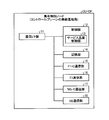
- FIG. 1 is a diagram illustrating the configuration of the communication system according to the embodiment.
- FIG. 2 is a diagram illustrating a configuration of a centralized control node (a radio base station on a control plane) according to the embodiment.
- FIG. 3 is a diagram illustrating a configuration of a centralized user data node (a radio base station that processes (user data) on a user plane) in the embodiment.
- FIG. 4 is a diagram illustrating a configuration of a terminal according to the embodiment.
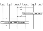
- FIG. 5 is a sequence diagram illustrating a first operation example including designation of service quality information in the embodiment.
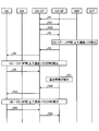
- FIG. 6 is a sequence diagram illustrating a second operation example including designation of service quality information in the embodiment.
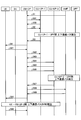
- FIG. 7 is a sequence diagram illustrating a third operation example including designation of service quality information in the embodiment.
- FIG. 8 is a sequence diagram illustrating a fourth operation example including designation of service quality information in the embodiment.
- FIG. 9 is a sequence diagram illustrating a fifth operation example including designation of service quality information in the embodiment.
- FIG. 10 is a sequence diagram illustrating a sixth operation example including designation of service quality information in the embodiment.
- FIG. 11 is a sequence diagram illustrating a seventh operation example including designation of service quality information in the embodiment.
- FIG. 12 is a sequence diagram illustrating an eighth operation example including designation of service quality information in the embodiment.
- FIG. 13 is a sequence diagram illustrating a ninth operation example including designation of service quality information in the embodiment.
- FIG. 14 is a diagram illustrating an example of a hardware configuration of a wireless device used in the embodiment.
- the communication system according to the embodiment will be described. 2. Description of the Related Art
- a communication system it is required to support services having various requirements according to the development of an IoT (Internet of Things) service (for example, a monitoring system for a traffic system, a smart meter, a device, and the like). Therefore, in the communication standard of the fifth generation mobile communication (5G), in addition to the standard technology of the fourth generation mobile communication (4G), further higher data rate, larger capacity, lower delay and higher reliability are required. There is a need for technologies that can be realized.
- IoT Internet of Things
- Radio base station gNB
- CU Central @ Unit
- DU distributed node
- the central node CU and the distribution node DU are connected via the F1 interface.
- CU and DU may be described as a communication device and a communication unit.
- the centralized control node CU-CP and the centralized user data node CU-UP multiplex signals in accordance with the transmission capacity and service type, and enable setting of a plurality of bearers and a plurality of flows. And various service requirements required by communication standards such as 5G. Note that a bearer is composed of one or more flows.
- the CU-CP and CU-UP may be described as a communication device and a communication unit.
- the MME which is a higher-level device of a wireless base station, performs control such as setting of a bearer between the SGW and the base station and between the SGW (Serving Gate Way) and the PGW (Packet data network Gateway).
- the function of MME is SMF (Session Management Management Function) and AMF (Access Management Mobile Management, Function, Function, Function, Function, Function, Function, Function, Function, Function, Function, Function, Function, Function)
- QoS Quality of Service
- SDAP Service Data
- the service quality (QoS) is an index for guaranteeing communication quality such as a transmission speed and a delay in a communication service in the communication system 1.
- the quality of service (QoS) can be specified by quality of service identification information (QI: QoS @ Identifier).
- the service quality identification information QI can include information such as a priority for performing priority control of data in a predetermined unit (for example, a flow unit).
- the service quality identification information QI which is one of the service quality information, can include a service quality identifier such as QCI (QoS ⁇ Class ⁇ Identifier), QFI (QoS ⁇ Flow ⁇ Identifier), and FPI (Flow ⁇ Priority ⁇ Identifier).
- QCI QoS ⁇ Class ⁇ Identifier
- QFI QoS ⁇ Flow ⁇ Identifier
- FPI Flow ⁇ Priority ⁇ Identifier
- the QCI is referred to as 5QI (5G @ QoS @ Identifier).
- the SDAP function provides service quality identification information in a downlink (DL: Down @ Link) which is a transmission from a network including a base station to a terminal and an uplink (UL: Up @ Link) which is a transmission from a terminal to a network including a base station.
- This is a function of associating (for example, mapping) a QI with a data radio bearer (DRB: Data @ Radio @ Bearer).
- the association means that, for example, the service quality identification information QI is assigned to the identifier (DRBI: DRB @ Identifier) of the data radio bearer, and the service quality identification information QI corresponds to the identifier DRBI of the data radio bearer. It is to be attached.
- the association information information related to the association, for example, the mapping information
- the association correspondence of the network node is set.
- the centralized node CU When the centralized node CU is divided (separated) into a function for handling control information and a function for handling user data, that is, it is separated into C-Plane and U-Plane (C / U (C-Plane / U-Plane)). (separation), a centralized control node (CU-CP, first node, centralized radio control node) and a centralized user data node (CU-UP, second node, centralized user data processing node) I do. Furthermore, the above-mentioned SDAP also performs C / U separation, and implementation of the SDAP protocol (SDAP function) in both CU-UP (SDAP-UP) and CU-CP (SDAP-CP) is conceivable.
- SDAP function SDAP protocol
- the centralized control node CU-CP transmits a control request to the centralized user data node CU-UP and a network from the centralized user data node CU-UP via E1 which is an interface between the CU-CP and the CU-UP.
- Resource information can be controlled by acquiring load information.
- the central control node CU-CP receives from the core network side.
- a header including the quality of service identification information QI (for example, in a ToS (Type of service) field) is added to the obtained data (packet) and can be transmitted to another network node (centralized user data node CU-UP, terminal UE). It is also thought.
- a centralized control node CU-CP as a radio base station (which processes control and control information) on the control plane and a centralized user data node CU-UP as a radio base station (which processes user data) on the user plane
- the association information controlled by the central control node CU-CP may not be set in another network node (centralized user data node CU-UP, terminal UE).
- association information different from the association information controlled by the central control node CU-CP is set in another network node (centralized user data node CU-UP, terminal UE). In this case, data communication between the centralized control node CU-CP and another network node (centralized user data node CU-UP, terminal UE) may not be performed properly.
- the central control node CU-CP transmits the service quality identification information (the central user data node CU-UP and / or the terminal UE) to the other network nodes (the central user data node CU-UP and / or the terminal UE) when DRB is set.
- the service quality identification information (information on the service quality) QI can be shared with the other network nodes, and based on the service quality. Enable data communication.
- FIG. 1 is a diagram illustrating a configuration of the communication system 1.
- the centralized node CU includes a centralized control node CU-CP as a radio base station of a control plane (CP: Control @ Plane) related to radio control and a radio base station of a user plane (UP: User @ Plane) related to data communication.
- CP Control @ Plane
- UP User @ Plane
- the central control node CU-CP is communicably connected to an access management function (AMF: Access ⁇ Management ⁇ Function, access management unit) via an NG-C interface.
- AMF Access ⁇ Management ⁇ Function, access management unit
- the central control node CU-CP is communicably connected to one or more central user data nodes CU-UP-1 and CU-UP-2 via the E1 interface.
- the centralized control node CU-CP is communicably connected to one or a plurality of distributed nodes DU-1, DU-2, and DU-3 via the F1-C interface.
- Each of the plurality of centralized user data nodes CU-UP-1, CU-UP-2 is connected to one or more of the distributed nodes DU-1, DU-2, DU-3 via the F1-U interface. Connected for communication.
- the F1-C interface and the F1-U interface are C / U separated from the F1 interface.
- Each of the distribution nodes DU-1, DU-2, and DU-3 is communicably connected to one or a plurality of terminals UE-1, UE-2, and UE-3 via a radio line.
- Each of the NG-C interface, the E1 interface, the F1-C interface, and the F1-U interface may be a wired line or a wireless line.
- the CU-UP is connected to a user data server (gateway) UPF via an NG-U interface. That is, NG-C and NG-U are obtained by separating the NG interface by C / U.
- a plurality of centralized user data nodes CU-UP-1 and CU-UP-2 are not distinguished from each other, they are simply referred to as a centralized user data node CU-UP.
- distributed nodes DU-1, DU-2, and DU-3 are not distinguished from each other, they are simply referred to as distributed nodes DU.
- terminals UE are simply referred to as terminals UE.
- the central control node CU-CP can be configured as shown in FIG.
- FIG. 2 is a diagram showing a configuration of the central control node CU-CP.
- the central control node CU-CP includes a communication interface unit (communication I / F unit) 11, a control unit 12, a storage unit 14, an F1-C communication unit 15, an E1 communication unit 16, an NG-C communication unit 17, and a UE communication. It has a part 18.
- the control unit 12 may be provided with an SDAP function (SDAP protocol).
- the control unit 12 When establishing communication between the success management server AMF and the central control node CU-CP via the NG-C interface, the control unit 12 generates association information and stores it in the storage unit 14.
- the association information is information in which the service quality identification information QI-1 is associated (associated) with the radio bearer DRB-1, and the service quality identification information QI-1 is added to the identifier DRBI-1 of the radio bearer DRB-1. Corresponding.
- the control unit 12 includes a service quality control unit 13.
- the service quality control unit 13 controls so that the value of the service quality identification information that matches with another network node at the time of DRB setting is set.
- the control unit 12 generates a bearer setting request for the radio bearer DRB-1 in order to establish communication between CU-UP-1 and DU (and between DU and UE).
- the service quality control unit 13 refers to the association information stored in the storage unit 14 and authenticates the service quality identification information QI-1 associated with the radio bearer DRB-1 (for example, the network node).
- an instruction to specify the association with the radio bearer DRB-1 is included in the bearer setting request of the radio bearer DRB-1.
- the communication I / F unit 11 transmits a bearer setting request of the radio bearer DRB-1 including the designation of the service quality identification information QI-1 to another network node (for example, the centralized user data node CU-UP, the terminal UE).
- another network node for example, the centralized user data node CU-UP, the terminal UE.
- the central user data node CU-UP can be configured as shown in FIG.
- FIG. 3 is a diagram showing a configuration of the centralized user data node CU-UP.
- the centralized user data node CU-UP has a communication interface unit (communication I / F unit) 21, a control unit 22, a storage unit 24, an F1-U communication unit 25, and an E1 communication unit 26.
- the control unit 22 may implement an SDAP function (SDAP protocol).
- the communication I / F unit 21 receives a bearer setting request for the radio bearer DRB-1 including the designation of the service quality identification information QI-1 from the central control node CU-CP.
- the control unit 22 has a service quality control unit 23.
- the service quality control unit 23 controls so that the value of the service quality identification information that matches with another network node at the time of DRB setting is set.
- the control unit 22 establishes communication with the user data server UPF according to the bearer setting request of the radio bearer DRB-1.
- the service quality control unit 23 associates the service quality identification information QI-1 with the radio bearer DRB-1 (for example, the association information). Is generated and stored in the storage unit 24.
- the service quality identification information QI-1 is associated with the radio bearer identification information (for example, the identifier of the radio bearer DRB-1).
- the communication I / F unit 21 can perform appropriate communication with the user data server UPF according to the service quality identification information QI-1 according to the association information.
- the terminal UE can be configured as shown in FIG.
- FIG. 4 is a diagram illustrating a configuration of the terminal UE.
- the terminal UE has a plurality of antennas 2 and 9, a communication interface unit (communication I / F unit) 3, a control unit 6, and a storage unit 8.
- the communication interface unit 3 has a wireless transmission unit 4 and a wireless reception unit 5.
- the wireless transmission unit 4 is connected to the antenna 2.
- the wireless receiving section 5 is connected to the antenna 9.
- FDD Frequency / Division / Duplex
- the control unit 6 can implement an SDAP function (SDAP protocol).
- SDAP protocol Secure Digital Protocol
- the wireless transmitting unit 4 and the wireless receiving unit 5 may be connected to the same antenna (for example, the antenna 2). That is, TDD (Time ⁇ Division ⁇ Duplex) may be used.
- the communication I / F unit 3 receives from the central control node CU-CP a bearer setting request for the radio bearer DRB-1 including the service quality identification information QI-1 (information related to service quality).
- the control unit 6 has a service quality control unit 7.
- the service quality control unit 7 controls to set the value of the service quality identification information that matches with another network node when the DRB is set.
- the control unit 6 establishes communication with the centralized user data node CU-UP according to the bearer setting request of the radio bearer DRB-1.
- the service quality control unit 7 generates association information in which the service quality identification information QI-1 is mapped (associated) to the radio bearer DRB-1 in response to the bearer setting request of the radio bearer DRB-1. It is stored in the storage unit 8.
- the service quality identification information QI-1 is associated with the radio bearer identification information (for example, the identifier of the radio bearer DRB-1).
- the communication I / F unit 3 can perform appropriate communication with the centralized user data node CU-UP according to the service quality identification information QI-1 according to the association information.
- the service quality identification information QI can be specified.
- the service quality identification information QI includes a value indicating the priority (or priority)
- it can be specified by any of the following patterns (1) to (3).
- (1) Specification of immediate value of service quality identification information: Example (service quality identification information QI 50)
- Example (service quality identification information QI 46, 48, 50, 52)
- Example (service quality identification information QI 40 to 60)
- FIG. 5 is a sequence diagram showing a first operation example including designation of service quality identification information.
- the centralized control node upon receiving from the success management server AMF a setting request “Initial ⁇ Context ⁇ Setup ⁇ Request” of the terminal UE including a notification “Accept” of the completion of the establishment of the core-side communication path (S1), the centralized control node
- the CU-CP sets the radio bearer by specifying (pattern (1)) the immediate value (for example, ID number) of the service quality identification information QI.
- the centralized user data node CU-UP generates a bearer setting result notification “DRB ⁇ Setup ⁇ Response” and returns it to the centralized control node CU-CP (S3).
- the central control node CU-CP confirms that the communication path with the centralized user data node CU-UP user data server UPF has been established by receiving the bearer setting result notification “DRB ⁇ Setup ⁇ Response”.
- the association information associated with the DRB-1 is generated and stored in the storage unit 8.
- the terminal UE generates a bearer setting result notification “Connection ⁇ Reconfiguration ⁇ Complete” and returns it to the central control node CU-CP (S5).
- the centralized control node CU-CP confirms that the communication path between the terminal UE and the centralized user data node CU-UP has been established by receiving the bearer setting result notification "Connection ⁇ Reconfiguration ⁇ Complete”.
- S3 may be performed before a communication path with the centralized user data node CU-UP user data server UPF is established.
- S5 may be performed before a communication path between the terminal UE and the centralized user data node CU-UP is established.
- S2 and S3 may be performed before the communication path between the central control node CU-CP and the access management server AMF is established (before S1).
- FIG. 6 is a sequence diagram showing a second operation example including designation of service quality identification information.
- the central control node CU-CP specifies the service quality identification information QI with a plurality of direct values (pattern ( 2)) or the setting in the value range (pattern (3)) sets the radio bearer.
- FIG. 7 is a sequence diagram showing a third operation example including designation of service quality identification information.
- the central control node CU-CP specifies the service quality identification information QI with a plurality of immediate values (pattern ( 2)) or the setting in the value range (pattern (3)) sets the radio bearer.
- the centralized user data node CU-UP generates a bearer setting result notification “DRB ⁇ Setup ⁇ Response” and returns it to the centralized control node CU-CP (S22).
- the association information associated with the DRB-1 is generated and stored in the storage unit 8.
- the terminal UE generates a bearer setting result notification “Connection ⁇ Reconfiguration ⁇ Complete” and returns it to the central control node CU-CP (S24).
- the centralized control node CU-CP confirms that the communication path between the terminal UE and the centralized user data node CU-UP has been established by receiving the bearer setting result notification "Connection ⁇ Reconfiguration ⁇ Complete”.
- FIG. 8 is a sequence diagram showing a fourth operation example including designation of service quality identification information.
- the central control node CU-CP transmits a plurality of pieces of service quality identification information QI before setting the radio bearer.
- An inquiry is made for service quality identification information that can be set by specifying a direct value (pattern (2)) or specifying a value range (pattern (3)).
- a request “DRB ⁇ Range ⁇ Check” is generated and transmitted to the centralized user data node CU-UP (S31).
- the central user data node CU-UP generates a configurable notification "DRB ⁇ Range ⁇ Check ⁇ Response" and returns it to the central control node CU-CP (S32).
- FIG. 9 is a sequence diagram showing a fifth operation example including designation of service quality identification information.
- S31 and S32 are performed as in the fourth operation example.
- S2 to S5 are performed in the same manner as in the first operation example.
- the association information associated with the DRB-1 is generated and stored in the storage unit 8.
- the terminal UE generates a bearer setting result notification “Connection ⁇ Reconfiguration ⁇ Complete” and returns it to the central control node CU-CP (S44).
- FIG. 10 is a sequence diagram showing a sixth operation example including designation of service quality identification information.
- S1 is performed as in the first operation example
- S31 and S32 are performed as in the fourth operation example.
- S2 to S5 are performed in the same manner as in the first operation example.
- the association information associated with the DRB-1 is generated and stored in the storage unit 8.
- the terminal UE generates a bearer setting result notification “Connection ⁇ Reconfiguration ⁇ Complete” and returns it to the central control node CU-CP (S54).
- FIG. 11 is a sequence diagram showing a seventh operation example including designation of service quality identification information.
- S31 and S32 are performed as in the fourth operation example.
- S2 to S4 are performed in the same manner as in the first operation example.
- the centralized control node CU-CP confirms that the communication path between the centralized user data node CU-UP-1 and the user data server UPF has been deleted by receiving the bearer deletion result notification “DRB ⁇ Delete ⁇ Response”.
- the central control node CU-CP selects the central user data node CU-UP-2 as a partner to establish a communication path with the user data server UPF, and sets the service before setting the radio bearer.
- An inquiry about service quality identification information that can be set by designating a value range of the quality identification information QI (pattern (3)) is performed.
- the data is transmitted to CU-UP-2 (S64).
- the centralized user data node CU-UP-2 generates a bearer setting result notification “DRB ⁇ Setup ⁇ Response” and returns it to the centralized control node CU-CP (S67).
- the central control node CU-CP Upon receiving the bearer setting result notification “DRB Setup ⁇ Response”, the central control node CU-CP generates a core-side communication path change request “UE Context Modification Request” and transmits it to the success management server AMF (S68).
- the request for changing the communication path on the core side indicates that the communication path between the central user data node CU-UP-2 and the user data server UPF has been established instead of the central user data node CU-UP-1. Includes notification of changes.
- the success management server AMF switches the communication path on the core side from the communication path for the centralized user data node CU-UP-1 to the communication path for the centralized user data node CU-UP-2.
- a notification “UE ⁇ Context ⁇ Modification ⁇ Response” of the communication path establishment completion is generated and returned to the central control node CU-CP (S69).
- the central control node CU-CP receives the notification “UE Context Modification Response” of the completion of the establishment of the communication path on the core side, thereby completing the switching of the communication path for the centralized user data node CU-UP-2 on the core side. Check.
- the association information (for example, association information) that associates the DRB-1 is generated and stored in the storage unit 8.
- the terminal UE generates a bearer setting result notification "Connection @ Reconfiguration @ Complete” and returns it to the central control node CU-CP (S92).
- the central control node CU-CP confirms that the communication path between the terminal UE and the central user data node CU-UP-2 has been established by receiving the bearer setting result notification “Connection ⁇ Reconfiguration ⁇ Complete”.
- the centralized control node CU-CP in response to the inability of the terminal UE to accept the service quality identification information that can be set in the centralized user data node CU-UP-1, the centralized control node CU-CP and the centralized user data
- FIG. 12 is a sequence diagram showing an eighth operation example including designation of service quality identification information.
- S31 and S32 are performed as in the fourth operation example.
- S2 to S5 are performed in the same manner as in the first operation example.
- the centralized user data node CU-UP periodically detects the communication load and transmits the detection result to the centralized control node CU-CP as a load notification “Load @ Information” (S71).
- the central control node CU-CP Upon receiving the load notification “Load @ Information”, the central control node CU-CP determines whether or not the communication load of the centralized user data node CU-UP has changed according to the load notification. That is, the centralized control node CU-CP determines whether the communication load of the centralized user data node CU-UP has been reduced and the free space of the circuit capacity has been expanded (whether the free bandwidth has been expanded) or It is determined whether the communication load of the CU-UP has increased and the free space in the line capacity has been reduced (whether the free bandwidth has been reduced).
- the central control node CU-CP confirms that the setting change of the communication path between the terminal UE and the centralized user data node CU-UP has been completed by receiving the bearer change result notification “DRB ⁇ Modify ⁇ Response”.
- the association information associated with the DRB-1 is generated and stored in the storage unit 8.
- the terminal UE generates a bearer setting result notification “Connection ⁇ Reconfiguration ⁇ Complete” and returns it to the central control node CU-CP (S76).
- the central control node CU-CP confirms that the setting change of the communication path between the terminal UE and the centralized user data node CU-UP has been completed by receiving the bearer setting result notification "Connection ⁇ Reconfiguration ⁇ Complete”.
- FIG. 13 is a sequence diagram showing a ninth operation example including designation of service quality identification information.
- S1 is performed as in the first operation example
- S31 and S32 are performed as in the fourth operation example.
- S2 to S5 are performed in the same manner as in the first operation example.
- the terminal UE periodically detects the communication load, and determines whether or not the communication load of the terminal UE has changed according to the detection result. That is, the terminal UE determines whether the communication load of the terminal UE is reduced and the free band of the radio bearer is expanded, or whether the communication load of the terminal UE is increased and the free band of the radio bearer is reduced. .
- the central user data node CU-UP generates a configurable notification "DRB ⁇ Range ⁇ Check ⁇ Response" and returns it to the central control node CU-CP (S84).
- the central control node CU-CP Upon receiving the configurable notification "DRB ⁇ Range ⁇ Check ⁇ Response", the central control node CU-CP generates a bearer change request "DRB ⁇ Modify ⁇ Request" in response to the configurable notification and transmits the request to the centralized user data node CU-UP. (S85).
- the central control node CU-CP confirms that the setting change of the communication path between the terminal UE and the centralized user data node CU-UP has been completed by receiving the bearer change result notification “DRB ⁇ Modify ⁇ Response”.
- the association information associated with the DRB-1 is generated and stored in the storage unit 8.
- the terminal UE generates a bearer setting result notification “Connection ⁇ Reconfiguration ⁇ Complete” and returns it to the central control node CU-CP (S88).
- the central control node CU-CP confirms that the setting change of the communication path between the terminal UE and the centralized user data node CU-UP has been completed by receiving the bearer setting result notification "Connection ⁇ Reconfiguration ⁇ Complete”.
- the service quality identification of the radio bearer DRB-1 is performed between the central control node CU-CP, the central user data node CU-UP, and the terminal UE in response to the change of the communication load of the terminal UE.
- the central control node CU-CP provides service quality to other network nodes (centralized user data node CU-UP and / or terminal UE) at the time of DRB setting or the like. Notify identification information. Thereby, the value of the service quality identification information QI that can be shared by the central control node CU-CP with other network nodes can be matched, and data communication in the communication system 1 can be appropriately performed. . Thereby, the quality of the communication service required for the communication system 1 can be guaranteed.
- each component of each part illustrated in the embodiment does not necessarily need to be physically configured as illustrated.
- the specific form of distribution / integration of each unit is not limited to the one shown in the figure, and all or a part of it is functionally or physically distributed / integrated in arbitrary units according to various loads and usage conditions. Can be configured.
- each device various processing functions performed by each device are implemented by a CPU (Central Processing Unit) (or a microcomputer such as an MPU (Micro Processing Unit)) or an MCU (Micro Controller Unit) or the like. It may be executed.
- the various processing functions may be entirely or arbitrarily executed on a program that is analyzed and executed by a CPU (or a microcomputer such as an MPU or an MCU) or on hardware by wired logic. .
- the wireless device of the embodiment (that is, the centralized control node CU-CP, the centralized user data node CU-UP, the distributed node DU, the terminal UE) can be realized by, for example, the following hardware configuration.
- FIG. 14 is a diagram illustrating an example of a hardware configuration of a wireless device.
- the wireless device 100 includes a processor 101, a memory 102, a current sensor 103, a current circuit 104, and an RF circuit 105.
- the processor 101 include a CPU, a DSP (Digital Signal Processor), and an FPGA (Field Programmable Gate Array).
- the memory 102 include a random access memory (RAM) such as an SDRAM (Synchronous Dynamic Access Memory), a ROM (Read Only Memory), and a flash memory.
- RAM random access memory
- the various processing functions performed by the wireless device according to the embodiment may be realized by executing a program stored in various memories such as a nonvolatile storage medium by a processor. That is, a program corresponding to each process may be recorded in the memory 102, and each program may be executed by the processor 101. Further, the communication I / F unit can be realized by the RF circuit 105.
- Communication System 3 Communication I / F Unit 6
- Control Unit 8 Storage Unit 11
- Control Unit 14 Storage Unit 21
Landscapes
- Engineering & Computer Science (AREA)
- Computer Networks & Wireless Communication (AREA)
- Signal Processing (AREA)
- Mobile Radio Communication Systems (AREA)
Abstract
第1の集中ノードは、一つの態様において、コントロールプレーンの無線基地局として機能する第1の集中ノードであって、第1のサービス品質識別情報を第1の無線ベアラに関連付けることを要求する第1のベアラ設定要求を生成する制御部と、前記生成された第1のベアラ設定要求を他のネットワークノードへ送信する通信インターフェースとを有する。
Description
本発明は、第1の集中ノード、第2の集中ノード、端末、通信システム、及び処理方法に関する。
現在のネットワークは、モバイル端末(スマートフォンやフューチャーホン)のトラフィックがネットワークのリソースの大半を占めている。また、モバイル端末が使うトラフィックは、今後も拡大していく傾向にある。一方で、IoT(Internet of a Things)サービス(例えば、交通システム、スマートメータ、装置等の監視システム)の展開にあわせて、多様な要求条件を持つサービスに対応することが求められている。そのため、第5世代移動体通信(5G)の通信規格では、第4世代移動体通信(4G)の標準技術に加えて、さらなる高データレート化、大容量化、低遅延化、及び高信頼化を実現する技術が求められている。
3GPP TSG RAN WG3 Meeting #97, TDocs "R3-173065", Title "Considerations for Separation of CP and UP in CU"
3GPP TS 37.324 V1.6.0 (2018-05)
3GPP TS 38.300 V15.1.0 (2018-03)
しかしながら、第5世代移動体通信の通信規格に従った通信システムにおいて、複数のネットワークノード間でデータベアラ又はデータ無線ベアラを新設する際等において、サービス品質が適切に設定されない可能性がある。
開示の技術は、上記に鑑みてなされたものであって、複数のネットワークノード間でサービス品質を適切に設定できる第1の集中ノード、第2の集中ノード、端末、及び通信システムを提供することを目的とする。
本願の開示する第1の集中ノードは、一つの態様において、コントロールプレーンの(制御及び制御情報を処理する)無線基地局である第1の集中ノード(集中制御ノード)であって、第1のサービス品質識別情報(サービス品質に関する情報)を前記無線基地局と端末間の第1の無線ベアラに関連付けることを要求する第1のベアラ設定要求を生成する制御部と、前記生成された第1のベアラ設定要求を他のネットワークノード(又はネットワークに接続される装置)へ送信する通信部とを有する。
本願の開示する無線装置の一つの態様によれば、複数のネットワークノード間でサービス品質を適切に設定できる。
以下に、本願の開示する通信システムの実施例を図面に基づいて詳細に説明する。なお、この実施例により開示技術が限定されるものではない。また、実施例において同一の機能を有する構成には同一の符号を付し、重複する説明は省略される。
実施例にかかる通信システムについて説明する。通信システムでは、IoT(Internet of a Things)サービス(例えば、交通システム、スマートメータ、装置等の監視システム)の展開にあわせて、多様な要求条件を持つサービスに対応することが求められている。そのため、第5世代移動体通信(5G)の通信規格では、第4世代移動体通信(4G)の標準技術に加えて、さらなる高データレート化、大容量化、低遅延化及び高信頼化を実現する技術が求められている。
なお、以下5Gシステムを例として説明するが、断りのない限り他の無線システム(例えば、4Gシステム)においても同様に実施可能である。
5G等の通信規格では、高速伝送、低遅延、高信頼、大量の通信デバイスの収容等、提供する通信サービスにより、異なる無線通信環境の提供が求められている。このため、周波数帯域幅を拡げられるミリ波帯の周波数を用いたり、セル半径を小さくしたりするなどの対策を実施することで、通信デバイスの収容数を増加し、高速かつ低遅延通信を可能としている。これにより、セル数が増加するため、無線基地局(gNB)を、無線制御を行う集中ノード(CU:Central Unit、第3のノード、無線制御ノード)と端末と無線通信を行う分散ノード(DU:Distributed Unit、第4のノード、無線通信ノード)とに分割する。なお、集中ノードCUと分散ノードDUは、F1インターフェースを介して接続される。なお、CU及び、DUを通信装置、通信ユニットと記載しても良い。
通信システム1では、集中制御ノードCU-CP及び集中ユーザデータノードCU-UPのそれぞれにおいて伝送容量やサービス種類に合わせ信号を多重化するとともに複数のベアラや複数のフローの設定を可能とすることで、5G等の通信規格で求められる様々なサービス要件に対応することが可能となる。なお、ベアラは1つ以上のフローで構成される。なお、CU-CP及び、CU-UPを通信装置、通信ユニットと記載しても良い。
従来の通信規格、例えばLTEでは、無線基地局の上位装置であるMMEがSGWと基地局間及びSGW(Serving Gate Way)とPGW(Packet data network Gate Way)間のベアラの設定等の制御を実施していた。5G等の通信規格では、ネットワークの仮想化を前提として、MME(Mobility Management Entity)の機能がSMF(Session Management Function)やAMF(Access and Mobility management Function)に分けられ、SGWがUPF(User Plane Function)となった。サービス品質(QoS:Quality of Service)の制御をフロー単位で実施するために、無線基地局にQoS制御を行なうSDAP(Service Data Adaptation Protocol)の機能が追加され得る。
サービス品質(QoS)は、通信システム1における通信サービスにおける伝送速度や遅延などの通信品質を保証するための指標である。サービス品質(QoS)は、サービス品質識別情報(QI:QoS Identifier)で指定され得る。サービス品質識別情報QIは、データを所定の単位(例えば、フロー単位)で優先制御するための優先度等の情報を含むことができる。例えば、サービス品質情報のひとつであるサービス品質識別情報QIは、QCI(QoS Class Identifier)、QFI(QoS Flow Identifier)、FPI(Flow Priority Identifier)などのサービス品質識別子を含むことができる。なお、5Gでは、QCIを5QI(5G QoS Identifier)と呼ぶ。
SDAP機能は、基地局を含むネットワークから端末への伝送であるダウンリンク(DL:Down Link)及び端末から基地局を含むネットワークへの伝送であるアップリンク(UL:Up Link)においてサービス品質識別情報QIをデータ無線ベアラ(DRB:Data Radio Bearer)に関連付ける(例えば、マッピングする)機能である。なお、ここで関連付け(例えば、マッピング)とは、例えば、データ無線ベアラの識別子(DRBI:DRB Identifier)にサービス品質識別情報QIが割り当てられ、データ無線ベアラの識別子DRBIにサービス品質識別情報QIが対応付けられることである。関連付け情報(関連付けに関する情報、例えば、マッピング情報)が生成されることで、ネットワークノードに対して関連付けの対応関係が設定される。
集中ノードCUを、制御情報を扱う機能と、ユーザデータを扱う機能とに分割(分離)する場合、すなわち、C-PlaneとU-Planeとに分離する(C/U(C-Plane/U-plane)分離)場合、集中制御ノード(CU-CP、第1のノード、集中無線制御ノード)と集中ユーザデータノード(CU-UP、第2のノード、集中ユーザデータ処理ノード)に分割(分離)する。更に、上述のSDAPもC/U分離を実施し、CU-UP(SDAP-UP)及びCU-CP(SDAP-CP)双方でのSDAPプロトコル(SDAP機能)の実装が考えられる。このとき、CU-CPとCU-UPのインターフェースであるE1を介して、集中制御ノードCU-CPは、集中ユーザデータノードCU-UPに対する制御要求の送信や集中ユーザデータノードCU-UPからのネットワークの負荷(Load)情報取得等によるリソース情報の制御を行うことができる。
例えば、サービス品質識別情報QIがデータ無線ベアラ(DRB:Data Radio Bearer)に関連付けされていれば(すなわち、関連付け情報が格納されていれば)、集中制御ノードCU-CPは、コアネットワーク側から受信されたデータ(パケット)にそのサービス品質識別情報QIを(例えばToS(Type of service)フィールドに)含むヘッダを付加して他のネットワークノード(集中ユーザデータノードCU-UP、端末UE)に送信できるようにも考えられる。
しかし、コントロールプレーンの(制御及び制御情報を処理する)無線基地局としての集中制御ノードCU-CPとユーザプレーンの(ユーザデータを処理する)無線基地局としての集中ユーザデータノードCU-UPとが互いに分離して構成される場合、集中制御ノードCU-CPで制御される関連付け情報が他のネットワークノード(集中ユーザデータノードCU-UP、端末UE)で未設定である可能性がある。あるいは、集中制御ノードCU-CP側で制御される関連付け情報と異なる関連付け情報が他のネットワークノード(集中ユーザデータノードCU-UP、端末UE)で設定されている可能性がある。この場合、集中制御ノードCU-CPと他のネットワークノード(集中ユーザデータノードCU-UP、端末UE)との間におけるデータ通信が適切に行われない可能性がある。
そこで、実施形態では、通信システム1において、集中制御ノードCU-CPが、DRB設定時等に、他のネットワークノード(集中ユーザデータノードCU-UP及び/又は端末UE)に対しサービス品質識別情報(サービス品質を識別するための情報、サービス品質に関する情報)を通知することで、他のネットワークノードとの間でサービス品質識別情報(サービス品質に関する情報)QIを共有可能とし、該サービス品質に基づいたデータ通信を可能とする。
具体的には、通信システム1は、5G等の通信規格に従って、図1に示すように構成され得る。図1は、通信システム1の構成を示す図である。通信システム1では、集中ノードCUが、無線制御に関するコントロールプレーン(CP:Control Plane)の無線基地局としての集中制御ノードCU-CPと、データ通信に関するユーザプレーン(UP:User Plane)の無線基地局としての集中ユーザデータノードCU-UPとに分割される。集中制御ノードCU-CPは、NG-Cインターフェースを介して、アクセス管理機能(AMF:Access Management Function、アクセス管理部)と通信可能に接続されている。集中制御ノードCU-CPは、E1インターフェースを介して、1つ又は複数の集中ユーザデータノードCU-UP-1,CU-UP-2のそれぞれと通信可能に接続されている。集中制御ノードCU-CPは、F1-Cインターフェースを介して、1つ又は複数の分散ノードDU-1,DU-2,DU-3のそれぞれと通信可能に接続されている。複数の集中ユーザデータノードCU-UP-1,CU-UP-2のそれぞれは、F1-Uインターフェースを介して、1つ又は複数の分散ノードDU-1,DU-2,DU-3のそれぞれと通信可能に接続されている。なお、F1-Cインターフェース及びF1-Uインターフェースは、F1インターフェースをC/U分離したものである。それぞれの分散ノードDU-1,DU-2,DU-3は、無線回線を介して、1つ又は複数の端末UE-1,UE-2,UE-3のうち端末と通信可能に接続されている。なお、NG-Cインターフェース、E1インターフェース、F1-Cインターフェース、F1-Uインターフェースのそれぞれは、有線回線であってもよいし、無線回線であってもよい。また、CU-UPはユーザデータサーバ(ゲートウェイ)UPFとNG-Uインターフェースを介して接続される。すなわちNG-CとNG-Uは、NGインターフェースをC/U分離したものである。
なお、複数の集中ユーザデータノードCU-UP-1,CU-UP-2を互いに区別しないときは、単に集中ユーザデータノードCU-UPとして示すことにする。複数の分散ノードDU-1,DU-2,DU-3を互いに区別しないときは、単に分散ノードDUとして示すことにする。複数の端末UE-1,UE-2,UE-3を互いに区別しないときは、単に端末UEとして示すことにする。
集中制御ノードCU-CPは、図2に示すように構成され得る。図2は、集中制御ノードCU-CPの構成を示す図である。集中制御ノードCU-CPは、通信インターフェース部(通信I/F部)11、制御部12、記憶部14、F1-C通信部15、E1通信部16、NG-C通信部17、及びUE通信部18を有する。制御部12には、SDAP機能(SDAPプロトコル)が実装され得る。
制御部12は、NG-Cインターフェースを介してサクセス管理サーバAMFと集中制御ノードCU-CP間の通信を確立する際に、関連付け情報を生成して記憶部14に格納する。関連付け情報は、サービス品質識別情報QI-1が無線ベアラDRB-1に関連付けされた(関係づけられた)情報であり、無線ベアラDRB-1の識別子DRBI-1にサービス品質識別情報QI-1が対応付けられている。
制御部12は、サービス品質制御部13を有する。サービス品質制御部13は、DRB設定時に他のネットワークノードとの間で一致したサービス品質識別情報の値の設定がなされるように制御する。制御部12は、CU-UP-1とDU間(及びDUとUE間)の通信を確立するために、無線ベアラDRB-1のベアラ設定要求を生成する。その際に、サービス品質制御部13は、記憶部14に格納された関連付け情報を参照し、無線ベアラDRB-1に関連付けされた(例えば、関連付けされた)サービス品質識別情報QI-1がネットワークノードでも無線ベアラDRB-1に関連付けされるように指定する指示を、無線ベアラDRB-1のベアラ設定要求に含ませる。これにより、通信I/F部11は、サービス品質識別情報QI-1の指定が含まれた無線ベアラDRB-1のベアラ設定要求を他のネットワークノード(例えば、集中ユーザデータノードCU-UP、端末UE)へ送信する。
集中ユーザデータノードCU-UPは、図3に示すように構成され得る。図3は、集中ユーザデータノードCU-UPの構成を示す図である。集中ユーザデータノードCU-UPは、通信インターフェース部(通信I/F部)21、制御部22、記憶部24、F1-U通信部25、及びE1通信部26を有する。制御部22には、SDAP機能(SDAPプロトコル)が実装され得る。
通信I/F部21は、サービス品質識別情報QI-1の指定が含まれた無線ベアラDRB-1のベアラ設定要求を集中制御ノードCU-CPから受信する。
制御部22は、サービス品質制御部23を有する。サービス品質制御部23は、DRB設定時に他のネットワークノードとの間で一致したサービス品質識別情報の値の設定がなされるように制御する。制御部22は、無線ベアラDRB-1のベアラ設定要求に従って、ユーザデータサーバUPFとの通信を確立する。その際に、サービス品質制御部23は、無線ベアラDRB-1のベアラ設定要求に応じて、サービス品質識別情報QI-1が無線ベアラDRB-1に関連付けられた(例えば、関連付けされた)関連付け情報を生成して記憶部24に格納する。関連付け情報では、無線ベアラ識別情報(例えば、無線ベアラDRB-1の識別子)にサービス品質識別情報QI-1が対応付けられている。
これにより、通信I/F部21は、関連付け情報に応じて、ユーザデータサーバUPFとの間でサービス品質識別情報QI-1に従った適切な通信を行うことができる。
端末UEは、図4に示すように構成され得る。図4は、端末UEの構成を示す図である。端末UEは、複数のアンテナ2,9、通信インターフェース部(通信I/F部)3、制御部6、及び記憶部8を有する。通信インターフェース部3は、無線送信部4及び無線受信部5を有する。無線送信部4は、アンテナ2に接続されている。無線受信部5は、アンテナ9に接続されている。なお、この場合はFDD(Frequency Division Duplex)となる。制御部6には、SDAP機能(SDAPプロトコル)が実装され得る。なお、図4には図示していないが、無線送信部4と無線受信部5が同じアンテナ(例えばアンテナ2)に接続されていてもよい。すなわち、TDD(Time Devision Duplex)としてもよい。
通信I/F部3は、サービス品質識別情報QI-1(サービス品質に関する情報)が含まれた無線ベアラDRB-1のベアラ設定要求を集中制御ノードCU-CPから受信する。
制御部6は、サービス品質制御部7を有する。サービス品質制御部7は、DRB設定時に他のネットワークノードとの間で一致したサービス品質識別情報の値の設定がなされるように制御する。制御部6は、無線ベアラDRB-1のベアラ設定要求に従って、集中ユーザデータノードCU-UPとの通信を確立する。その際に、サービス品質制御部7は、無線ベアラDRB-1のベアラ設定要求に応じて、サービス品質識別情報QI-1が無線ベアラDRB-1にマッピング(関連付け)された関連付け情報を生成して記憶部8に格納する。関連付け情報では、無線ベアラ識別情報(例えば、無線ベアラDRB-1の識別子)にサービス品質識別情報QI-1が対応付けられている。
これにより、通信I/F部3は、関連付け情報に応じて、集中ユーザデータノードCU-UPとの間でサービス品質識別情報QI-1に従った適切な通信を行うことができる。
より具体的には、通信システム1では、図5~図13に示すように、サービス品質識別情報QIが指定され得る。
例えば、サービス品質識別情報QIは、優先度の高さ(または優先順位)を示す値を含む場合、次の(1)~(3)のいずれかのパターンで指定され得る。
(1) サービス品質識別情報の直値での指定 : 例(サービス品質識別情報QI=50)
(2) サービス品質識別情報の複数の直値での指定 : 例(サービス品質識別情報QI=46,48,50,52)
(3) 許容するサービス品質識別情報の値レンジでの指定 : 例(サービス品質識別情報QI=40~60)
(1) サービス品質識別情報の直値での指定 : 例(サービス品質識別情報QI=50)
(2) サービス品質識別情報の複数の直値での指定 : 例(サービス品質識別情報QI=46,48,50,52)
(3) 許容するサービス品質識別情報の値レンジでの指定 : 例(サービス品質識別情報QI=40~60)
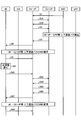
図5は、サービス品質識別情報の指定を含む第1の動作例を示すシーケンス図である。図5に示す第1の動作例では、コア側通信パス確立完了の通知「Accept」を含む端末UEの設定要求「Initial Context Setup Request」をサクセス管理サーバAMFから受けると(S1)、集中制御ノードCU-CPは、サービス品質識別情報QIの直値(例えば、ID番号)での指定(パターン(1))により無線ベアラの設定を行う。すなわち、集中制御ノードCU-CPは、サービス品質識別情報QI=50を選択し、選択されたサービス品質識別情報QI=50が無線ベアラDRB-1に関連付けされた関連付け情報を生成して記憶部14に格納する。それとともに、集中制御ノードCU-CPは、サービス品質識別情報QI=50を無線ベアラDRB-1に関連付けることを要求するベアラ設定要求「DRB Setup Request」を生成して集中ユーザデータノードCU-UPへ送信する(S2)。
集中ユーザデータノードCU-UPは、サービス品質識別情報QI=50の指定を含むベアラ設定要求「DRB Setup Request」を集中制御ノードCU-CPから受信すると、ベアラ設定要求に応じて、サービス品質識別情報QI=50が無線ベアラDRB-1に関連付けされた関連付け情報を生成して記憶部24に格納する。それとともに、集中ユーザデータノードCU-UPは、ベアラ設定結果通知「DRB Setup Response」を生成して集中制御ノードCU-CPへ返信する(S3)。ベアラ設定結果通知「DRB Setup Response」は、サービス品質識別情報QI=50の無線ベアラDRB-1への関連付けが完了したことの通知を含む。
集中制御ノードCU-CPは、ベアラ設定結果通知「DRB Setup Response」を受信することで、集中ユーザデータノードCU-UPユーザデータサーバUPFとの通信パスが確立したことを確認する。
また、集中制御ノードCU-CPは、サービス品質識別情報QI=50を無線ベアラDRB-1に関連付けることを要求するベアラ設定要求「Connection Reconfiguration」を生成して端末UEへ送信する(S4)。
端末UEは、サービス品質識別情報QI=50の指定を含むベアラ設定要求「Connection Reconfiguration」を集中制御ノードCU-CPから受信すると、ベアラ設定要求に応じて、サービス品質識別情報QI=50が無線ベアラDRB-1に関連付けされた関連付け情報を生成して記憶部8に格納する。それとともに、端末UEは、ベアラ設定結果通知「Connection Reconfiguration Complete」を生成して集中制御ノードCU-CPへ返信する(S5)。ベアラ設定結果通知「Connection Reconfiguration Complete」は、サービス品質識別情報QI=50の無線ベアラDRB-1への関連付けが完了したことの通知を含む。
集中制御ノードCU-CPは、ベアラ設定結果通知「Connection Reconfiguration Complete」を受信することで、端末UEと集中ユーザデータノードCU-UPとの通信パスが確立したことを確認する。
S1~S5のシーケンスにより、集中制御ノードCU-CP、集中ユーザデータノードCU-UP、及び端末UEの間において、無線ベアラDRB-1のサービス品質識別情報をQI=50で一致させることができる。
なお、S3は、集中ユーザデータノードCU-UPユーザデータサーバUPFとの通信パスが確立する前に行われてもよい。S5は、端末UEと集中ユーザデータノードCU-UPとの通信パスが確立する前に行われてもよい。S2,S3は、集中制御ノードCU-CPとアクセス管理サーバAMFとの通信パスが確立する前(S1の前)に行われてもよい。
図6は、サービス品質識別情報の指定を含む第2の動作例を示すシーケンス図である。図6に示す第2の動作例では、第1の動作例と同様にS1が行われた後に、集中制御ノードCU-CPは、サービス品質識別情報QIの複数の直値での指定(パターン(2))又は値レンジでの指定(パターン(3))により無線ベアラの設定を行う。
すなわち、集中制御ノードCU-CPは、サービス品質識別情報の複数の直値QI=46,48,50,52又は値レンジQI=40~60から選択されたサービス品質識別情報を無線ベアラDRB-1に関連付けることを要求するベアラ設定要求「DRB Setup Request」を生成して集中ユーザデータノードCU-UPへ送信する(S11)。ベアラ設定要求「DRB Setup Request」は、サービス品質識別情報の複数の直値QI=46,48,50,52又は値レンジQI=40~60の指定を含む。
集中ユーザデータノードCU-UPは、ベアラ設定要求「DRB Setup Request」を集中制御ノードCU-CPから受信すると、指定された値の範囲からサービス品質識別情報QI=50を選択する。集中ユーザデータノードCU-UPは、サービス品質識別情報QI=50が無線ベアラDRB-1に関連付けされた関連付け情報を生成して記憶部24に格納する。それとともに、集中ユーザデータノードCU-UPは、ベアラ設定結果通知「DRB Setup Response」を生成して集中制御ノードCU-CPへ返信する(S12)。ベアラ設定結果通知「DRB Setup Response」は、サービス品質識別情報QI=50の無線ベアラDRB-1への関連付けが完了したことの通知を含む。
集中制御ノードCU-CPは、ベアラ設定結果通知「DRB Setup Response」を受信することで、集中ユーザデータノードCU-UPでサービス品質識別情報QI=50が選択されたことを認識できる。これに応じて、集中制御ノードCU-CPは、選択されたサービス品質識別情報QI=50が無線ベアラDRB-1に関連付けされた関連付け情報を生成して記憶部14に格納する。
そして、第1の動作例と同様にS4,S5が行われる。
S1,S11,S12,S4,S5のシーケンスにより、集中制御ノードCU-CP、集中ユーザデータノードCU-UP、及び端末UEの間において、無線ベアラDRB-1のサービス品質識別情報をQI=50で一致させることができる。
図7は、サービス品質識別情報の指定を含む第3の動作例を示すシーケンス図である。図7に示す第3の動作例では、第1の動作例と同様にS1が行われた後に、集中制御ノードCU-CPは、サービス品質識別情報QIの複数の直値での指定(パターン(2))又は値レンジでの指定(パターン(3))により無線ベアラの設定を行う。
すなわち、集中制御ノードCU-CPは、サービス品質識別情報の複数の直値QI=50,52,54,58又は値レンジQI=50~60から選択されたサービス品質識別情報を無線ベアラDRB-1に関連付けることを要求するベアラ設定要求「DRB Setup Request」を生成して集中ユーザデータノードCU-UPへ送信する(S21)。
集中ユーザデータノードCU-UPは、サービス品質識別情報の複数の直値QI=50,52,54,58又は値レンジQI=50~60の指定を含むベアラ設定要求「DRB Setup Request」を集中制御ノードCU-CPから受信すると、通知された範囲のサービス品質識別情報での設定が不可能と判断し、次善(第2候補)の値として、通知された範囲外のサービス品質識別情報QI=48を選択する。集中ユーザデータノードCU-UPは、サービス品質識別情報QI=48が無線ベアラDRB-1に関連付けされた関連付け情報を生成して記憶部24に格納する。それとともに、集中ユーザデータノードCU-UPは、ベアラ設定結果通知「DRB Setup Response」を生成して集中制御ノードCU-CPへ返信する(S22)。ベアラ設定結果通知「DRB Setup Response」は、指定された範囲外の値としてサービス品質識別情報QI=48が無線ベアラDRB-1へ関連付けされたことの通知を含む。
集中制御ノードCU-CPは、ベアラ設定結果通知「DRB Setup Response」を受信することで、集中ユーザデータノードCU-UPでサービス品質識別情報QI=48が選択されたことを認識できる。この値を許容できる場合、集中制御ノードCU-CPは、選択されたサービス品質識別情報QI=48が無線ベアラDRB-1に関連付けされた関連付け情報を生成して記憶部14に格納する。
また、集中制御ノードCU-CPは、サービス品質識別情報QI=48を無線ベアラDRB-1に関連付けることを要求するベアラ設定要求「Connection Reconfiguration」を生成して端末UEへ送信する(S23)。
端末UEは、サービス品質識別情報QI=48の指定を含むベアラ設定要求「Connection Reconfiguration」を集中制御ノードCU-CPから受信すると、ベアラ設定要求に応じて、サービス品質識別情報QI=48が無線ベアラDRB-1に関連付けされた関連付け情報を生成して記憶部8に格納する。それとともに、端末UEは、ベアラ設定結果通知「Connection Reconfiguration Complete」を生成して集中制御ノードCU-CPへ返信する(S24)。ベアラ設定結果通知「Connection Reconfiguration Complete」は、サービス品質識別情報QI=48の無線ベアラDRB-1への関連付けが完了したことの通知を含む。
集中制御ノードCU-CPは、ベアラ設定結果通知「Connection Reconfiguration Complete」を受信することで、端末UEと集中ユーザデータノードCU-UPとの通信パスが確立したことを確認する。
S1,S21~S24のシーケンスにより、集中制御ノードCU-CP、集中ユーザデータノードCU-UP、及び端末UEの間において、無線ベアラDRB-1のサービス品質識別情報をQI=48で一致させることができる。
図8は、サービス品質識別情報の指定を含む第4の動作例を示すシーケンス図である。図8に示す第4の動作例では、第1の動作例と同様にS1が行われた後に、集中制御ノードCU-CPは、無線ベアラの設定の前に、サービス品質識別情報QIの複数の直値での指定(パターン(2))又は値レンジでの指定(パターン(3))により設定可能なサービス品質識別情報の問い合わせを行う。
すなわち、集中制御ノードCU-CPは、許容可能なサービス品質識別情報の範囲として、複数の直値QI=46,48,50,52又は値レンジQI=40~60を選択する。集中制御ノードCU-CPは、サービス品質識別情報の複数の直値QI=46,48,50,52又は値レンジQI=40~60のうち設定可能なサービス品質識別情報の値があるか問い合わせる問い合わせ要求「DRB Range Check」を生成して集中ユーザデータノードCU-UPへ送信する(S31)。
集中ユーザデータノードCU-UPは、サービス品質識別情報の複数の直値QI=46,48,50,52又は値レンジQI=40~60の指定を含む問い合わせ要求「DRB Range Check」を集中制御ノードCU-CPから受信すると、指定された値の範囲からサービス品質識別情報QI=50を設定可能であるとして選択する。そして、集中ユーザデータノードCU-UPは、設定可能通知「DRB Range Check Response」を生成して集中制御ノードCU-CPへ返信する(S32)。設定可能通知「DRB Range Check Response」は、サービス品質識別情報QI=50が集中ユーザデータノードCU-UPで設定可能であることの通知を含む。
そして、第1の動作例と同様にS2~S5が行われる。
S1,S31,S32,S2~S5のシーケンスにより、集中制御ノードCU-CP、集中ユーザデータノードCU-UP、及び端末UEの間において、無線ベアラDRB-1のサービス品質識別情報をQI=50で一致させることができる。
図9は、サービス品質識別情報の指定を含む第5の動作例を示すシーケンス図である。図9に示す第5の動作例では、第1の動作例と同様にS1が行われた後に、第4の動作例と同様にS31,S32が行われる。ただし、S32において、設定可能通知「DRB Range Check Response」は、サービス品質識別情報の値としてQI=50に代えてQI=48が集中ユーザデータノードCU-UPで設定可能であることの通知を含む。そして、第1の動作例と同様にS2~S5が行われる。
その後、集中ユーザデータノードCU-UPは、その通信負荷が軽減し無線ベアラの空き帯域が拡大すると(S41)、集中ユーザデータノードCU-UPで設定可能なサービス品質識別情報がQI=48からQI=52に変わったと判断し、更新要求「DRB Update Request」を生成して集中制御ノードCU-CPへ送信する(S42)。更新要求「DRB Update Request」は、集中ユーザデータノードCU-UPで設定可能なサービス品質識別情報がQI=48からQI=52に変わったことの通知を含む。
集中制御ノードCU-CPは、更新要求「DRB Update Request」を受信することで、集中ユーザデータノードCU-UPで設定可能なサービス品質識別情報がQI=48からQI=52に変わったことを認識し、サービス品質識別情報QI=52が無線ベアラDRB-1に関連付けされた関連付け情報を生成して記憶部14に格納する。それとともに、集中制御ノードCU-CPは、サービス品質識別情報QI=52を無線ベアラDRB-1に関連付けることを要求するベアラ設定要求「Connection Reconfiguration」を生成して端末UEへ送信する(S43)。
端末UEは、サービス品質識別情報QI=52の指定を含むベアラ設定要求「Connection Reconfiguration」を集中制御ノードCU-CPから受信すると、ベアラ設定要求に応じて、サービス品質識別情報QI=52が無線ベアラDRB-1に関連付けされた関連付け情報を生成して記憶部8に格納する。それとともに、端末UEは、ベアラ設定結果通知「Connection Reconfiguration Complete」を生成して集中制御ノードCU-CPへ返信する(S44)。ベアラ設定結果通知「Connection Reconfiguration Complete」は、サービス品質識別情報QI=52の無線ベアラDRB-1への関連付けが完了したことの通知を含む。
集中制御ノードCU-CPは、サービス品質識別情報QI=52の無線ベアラDRB-1へのマッピングが集中制御ノードCU-CP及び端末UEで行われたことを通知する更新結果通知「DRB Update Response」を生成して集中ユーザデータノードCU-UPへ送信する(S45)。
集中ユーザデータノードCU-UPは、サービス品質識別情報QI=52の指定を含む更新結果通知「DRB Update Response」を集中制御ノードCU-CPから受信すると、更新結果通知に応じたサービス品質識別情報QI=52が無線ベアラDRB-1に関連付けされた関連付け情報を生成して記憶部24に格納する。
S41~S45のシーケンスにより、集中ユーザデータノードCU-UPで設定可能なサービス品質識別情報が拡大した場合における集中制御ノードCU-CP、集中ユーザデータノードCU-UP、及び端末UEの間の無線ベアラDRB-1のサービス品質識別情報をQI=52で一致させることができる。
図10は、サービス品質識別情報の指定を含む第6の動作例を示すシーケンス図である。図10に示す第6の動作例では、第1の動作例と同様にS1が行われた後に、第4の動作例と同様にS31,S32が行われる。ただし、S32において、設定可能通知「DRB Range Check Response」は、サービス品質識別情報の値としてQI=50に代えてQI=52が集中ユーザデータノードCU-UPで設定可能であることの通知を含む。そして、第1の動作例と同様にS2~S5が行われる。
その後、集中ユーザデータノードCU-UPは、その通信負荷が増大し無線ベアラの空き帯域が縮小すると(S51)、集中ユーザデータノードCU-UPで設定可能なサービス品質識別情報がQI=52からQI=42に変わったと判断し、更新要求「DRB Update Request」を生成して集中制御ノードCU-CPへ送信する(S52)。更新要求「DRB Update Request」は、集中ユーザデータノードCU-UPで設定可能なサービス品質識別情報がQI=52からQI=42に変わったことの通知を含む。
集中制御ノードCU-CPは、更新要求「DRB Update Request」を受信することで、集中ユーザデータノードCU-UPで設定可能なサービス品質識別情報がQI=52からQI=42に変わったことを認識し、サービス品質識別情報QI=42が無線ベアラDRB-1に関連付けされた関連付け情報を生成して記憶部14に格納する。それとともに、集中制御ノードCU-CPは、サービス品質識別情報QI=42を無線ベアラDRB-1に関連付けることを要求するベアラ設定要求「Connection Reconfiguration」を生成して端末UEへ送信する(S53)。
端末UEは、サービス品質識別情報QI=42の指定を含むベアラ設定要求「Connection Reconfiguration」を集中制御ノードCU-CPから受信すると、ベアラ設定要求に応じて、サービス品質識別情報QI=42が無線ベアラDRB-1に関連付けされた関連付け情報を生成して記憶部8に格納する。それとともに、端末UEは、ベアラ設定結果通知「Connection Reconfiguration Complete」を生成して集中制御ノードCU-CPへ返信する(S54)。ベアラ設定結果通知「Connection Reconfiguration Complete」は、サービス品質識別情報QI=42の無線ベアラDRB-1への関連付けが完了したことの通知を含む。
集中制御ノードCU-CPは、サービス品質識別情報QI=42の無線ベアラDRB-1へのマッピングが集中制御ノードCU-CP及び端末UEで行われたことを通知する更新結果通知「DRB Update Response」を生成して集中ユーザデータノードCU-UPへ送信する(S55)。
集中ユーザデータノードCU-UPは、サービス品質識別情報QI=42の指定を含む更新結果通知「DRB Update Response」を集中制御ノードCU-CPから受信すると、更新結果通知に応じたサービス品質識別情報QI=42が無線ベアラDRB-1に関連付けされた関連付け情報を生成して記憶部24に格納する。
S51~S55のシーケンスにより、集中ユーザデータノードCU-UPで設定可能なサービス品質識別情報が減少した場合(設定可能なサービス識別子の範囲が縮小した場合)における集中制御ノードCU-CP、集中ユーザデータノードCU-UP、及び端末UEの間の無線ベアラDRB-1のサービス品質識別情報をQI=42で一致させることができる。
図11は、サービス品質識別情報の指定を含む第7の動作例を示すシーケンス図である。図11に示す第7の動作例では、第1の動作例と同様にS1が行われた後に、第4の動作例と同様にS31,S32が行われる。ただし、S32において、設定可能通知「DRB Range Check Response」は、サービス品質識別情報の値としてQI=50に代えてQI=48が集中ユーザデータノードCU-UPで設定可能であることの通知を含む。そして、第1の動作例と同様にS2~S4が行われる。
端末UEは、サービス品質識別情報QI=48の指定を含むベアラ設定要求「Connection Reconfiguration」を集中制御ノードCU-CPから受信すると、通知されたサービス品質識別情報の値での設定が不可能と判断し、次善の値として、通知された範囲外の値レンジQI=50~60を選択する。端末UEは、ベアラ設定要求に対する拒否応答「Connection Reconfiguration Reject」を生成して集中制御ノードCU-CPへ返信する(S61)。拒否応答「Connection Reconfiguration Reject」は、サービス品質識別情報の値レンジQI=50~60が端末UEで選択されたことの通知を含む。
拒否応答「Connection Reconfiguration Reject」を受信すると、集中制御ノードCU-CPは、サービス品質識別情報QI=48の無線ベアラDRB-1へのマッピングの削除を要求するベアラ削除要求「DRB Delete Request」を生成して集中ユーザデータノードCU-UP-1へ送信する(S62)。
集中ユーザデータノードCU-UP-1は、ベアラ削除要求「DRB Delete Request」を集中制御ノードCU-CPから受信すると、ベアラ削除要求に応じて、サービス品質識別情報QI=48が無線ベアラDRB-1に関連付けされた関連付け情報を記憶部24から削除する。それとともに、集中ユーザデータノードCU-UP-1は、ベアラ削除結果通知「DRB Delete Response」を生成して集中制御ノードCU-CPへ返信する(S63)。ベアラ削除結果通知「DRB Delete Response」は、サービス品質識別情報QI=48の無線ベアラDRB-1への関連付けの削除が完了したことの通知を含む。
集中制御ノードCU-CPは、ベアラ削除結果通知「DRB Delete Response」を受信することで、集中ユーザデータノードCU-UP-1とユーザデータサーバUPFとの通信パスが削除されたことを確認する。それに応じて、集中制御ノードCU-CPは、ユーザデータサーバUPFとの間で通信パスを確立すべき相手として集中ユーザデータノードCU-UP-2を選択し、無線ベアラの設定の前に、サービス品質識別情報QIの値レンジでの指定(パターン(3))により設定可能なサービス品質識別情報の問い合わせを行う。
すなわち、集中制御ノードCU-CPは、許容可能なサービス品質識別情報の範囲として、値レンジQI=50~60を選択する。集中制御ノードCU-CPは、サービス品質識別情報の値レンジQI=50~60のうち設定可能なサービス品質識別情報の値があるか問い合わせる問い合わせ要求「DRB Range Check」を生成して集中ユーザデータノードCU-UP-2へ送信する(S64)。
集中ユーザデータノードCU-UP-2は、サービス品質識別情報の値レンジQI=50~60の指定を含む問い合わせ要求「DRB Range Check」を集中制御ノードCU-CPから受信すると、指定された値の範囲からサービス品質識別情報QI=50を設定可能であるとして選択する。そして、集中ユーザデータノードCU-UP-2は、設定可能通知「DRB Range Check Response」を生成して集中制御ノードCU-CPへ返信する(S65)。設定可能通知「DRB Range Check Response」は、サービス品質識別情報QI=50が集中ユーザデータノードCU-UP-2で設定可能であることの通知を含む。
設定可能通知「DRB Range Check Response」を受信すると、集中制御ノードCU-CPは、設定可能通知に応じて、サービス品質識別情報QI=50が無線ベアラDRB-1に関連付けされた関連付け情報を生成して記憶部14に格納する。それとともに、集中制御ノードCU-CPは、サービス品質識別情報QI=50を無線ベアラDRB-1に関連付けることを要求するベアラ設定要求「DRB Setup Request」を生成して集中ユーザデータノードCU-UP-2へ送信する(S66)。
集中ユーザデータノードCU-UP-2は、サービス品質識別情報QI=50の指定を含むベアラ設定要求「DRB Setup Request」を集中制御ノードCU-CPから受信すると、ベアラ設定要求に応じて、サービス品質識別情報QI=50が無線ベアラDRB-1に関連付けされた関連付け情報を生成して記憶部24に格納する。それとともに、集中ユーザデータノードCU-UP-2は、ベアラ設定結果通知「DRB Setup Response」を生成して集中制御ノードCU-CPへ返信する(S67)。ベアラ設定結果通知「DRB Setup Response」は、サービス品質識別情報QI=50の無線ベアラDRB-1へのマッピングが完了したことの通知を含む。
ベアラ設定結果通知「DRB Setup Response」を受信すると、集中制御ノードCU-CPは、コア側通信パスの変更要求「UE Context Modification Request」を生成してサクセス管理サーバAMFへ送信する(S68)。コア側通信パスの変更要求「UE Context Modification Request」は、集中ユーザデータノードCU-UP-1に代えて集中ユーザデータノードCU-UP-2とユーザデータサーバUPFとの通信パスを確立したことの変更の通知を含む。
サクセス管理サーバAMFは、その変更の通知が許容できる場合、コア側の通信パスを集中ユーザデータノードCU-UP-1向けから集中ユーザデータノードCU-UP-2向けの通信パスに切り替え、コア側通信パス確立完了の通知「UE Context Modification Response」を生成して集中制御ノードCU-CPへ返信する(S69)。
集中制御ノードCU-CPは、コア側通信パス確立完了の通知「UE Context Modification Response」を受信することで、コア側で集中ユーザデータノードCU-UP-2向けの通信パスの切り替えが完了したことを確認する。
また、集中制御ノードCU-CPは、サービス品質識別情報QI=50を無線ベアラDRB-1に関連付けることを要求するベアラ設定要求「Connection Reconfiguration」を生成して端末UEへ送信する(S91)。
端末UEは、サービス品質識別情報QI=50の指定を含むベアラ設定要求「Connection Reconfiguration」を集中制御ノードCU-CPから受信すると、ベアラ設定要求に応じて、サービス品質識別情報QI=50と無線ベアラDRB-1とを関係付けされた関係付け情報(例えば、関連付け情報)を生成して記憶部8に格納する。それとともに、端末UEは、ベアラ設定結果通知「Connection Reconfiguration Complete」を生成して集中制御ノードCU-CPへ返信する(S92)。ベアラ設定結果通知「Connection Reconfiguration Complete」は、サービス品質識別情報QI=50の無線ベアラDRB-1への関連付けが完了したことの通知を含む。
集中制御ノードCU-CPは、ベアラ設定結果通知「Connection Reconfiguration Complete」を受信することで、端末UEと集中ユーザデータノードCU-UP-2との通信パスが確立したことを確認する。
S61~S69,S91,S92のシーケンスにより、端末UEが集中ユーザデータノードCU-UP-1で設定可能なサービス品質識別情報を許容できないことに対応して、集中制御ノードCU-CP、集中ユーザデータノードCU-UP-2、及び端末UEの間の無線ベアラDRB-1のサービス品質識別情報をQI=50で一致させることができる。
図12は、サービス品質識別情報の指定を含む第8の動作例を示すシーケンス図である。図12に示す第8の動作例では、第1の動作例と同様にS1が行われた後に、第4の動作例と同様にS31,S32が行われる。ただし、S32において、設定可能通知「DRB Range Check Response」は、サービス品質識別情報の値としてQI=50に代えてQI=48が集中ユーザデータノードCU-UPで設定可能であることの通知を含む。そして、第1の動作例と同様にS2~S5が行われる。
その後、集中ユーザデータノードCU-UPは、定期的に、その通信負荷を検知し検知結果を負荷通知「Load Information」として集中制御ノードCU-CPへ送信する(S71)。
負荷通知「Load Information」を受信すると、集中制御ノードCU-CPは、負荷通知に応じて、集中ユーザデータノードCU-UPの通信負荷の変更の有無を判断する。すなわち、集中制御ノードCU-CPは、集中ユーザデータノードCU-UPの通信負荷が軽減し回線容量の空きが拡大したか否か(空き帯域が拡大したか否か)、あるいは、集中ユーザデータノードCU-UPの通信負荷が増大し回線容量の空きが縮小したか否か(空き帯域が縮小したか否か)を判断する。
集中制御ノードCU-CPは、集中ユーザデータノードCU-UPの通信負荷が軽減し、空き帯域が拡大したと判断すると(S72)、集中ユーザデータノードCU-UPで設定可能なサービス品質識別情報がQI=48から複数の直値QI=50,52,54,56又は値レンジQI=50~60に変わったと判断し、ベアラ変更要求「DRB Modify Request」を生成して集中ユーザデータノードCU-UPへ送信する(S73)。ベアラ変更要求「DRB Modify Request」は、サービス品質識別情報の複数の直値QI=50,52,54,56又は値レンジQI=50~60の指定を含む。
集中ユーザデータノードCU-UPは、ベアラ変更要求「DRB Modify Request」を集中制御ノードCU-CPから受信すると、指定された値の範囲からサービス品質識別情報QI=50を選択する。集中ユーザデータノードCU-UPは、サービス品質識別情報QI=50が無線ベアラDRB-1に関連付けされた関連付け情報を生成して記憶部24に格納する。それとともに、集中ユーザデータノードCU-UPは、ベアラ変更結果通知「DRB Modify Response」を生成して集中制御ノードCU-CPへ返信する(S74)。ベアラ変更結果通知「DRB Modify Response」は、サービス品質識別情報QI=50の無線ベアラDRB-1への関連付けが完了したことの通知を含む。
集中制御ノードCU-CPは、ベアラ変更結果通知「DRB Modify Response」を受信することで、端末UEと集中ユーザデータノードCU-UPとの通信パスの設定変更が完了したことを確認する。
また、集中制御ノードCU-CPは、サービス品質識別情報QI=50を無線ベアラDRB-1に関連付けることを要求するベアラ設定要求「Connection Reconfiguration」を生成して端末UEへ送信する(S75)。
端末UEは、サービス品質識別情報QI=50の指定を含むベアラ設定要求「Connection Reconfiguration」を集中制御ノードCU-CPから受信すると、ベアラ設定要求に応じて、サービス品質識別情報QI=50が無線ベアラDRB-1に関連付けされた関連付け情報を生成して記憶部8に格納する。それとともに、端末UEは、ベアラ設定結果通知「Connection Reconfiguration Complete」を生成して集中制御ノードCU-CPへ返信する(S76)。ベアラ設定結果通知「Connection Reconfiguration Complete」は、サービス品質識別情報QI=50の無線ベアラDRB-1への関連付けが完了したことの通知を含む。
集中制御ノードCU-CPは、ベアラ設定結果通知「Connection Reconfiguration Complete」を受信することで、端末UEと集中ユーザデータノードCU-UPとの通信パスの設定変更が完了したことを確認する。
S71~S76のシーケンスにより、集中ユーザデータノードCU-UPの通信負荷の変更に対応して、集中制御ノードCU-CP、集中ユーザデータノードCU-UP、及び端末UEの間において、無線ベアラDRB-1のサービス品質識別情報をQI=50で一致させることができる。
図13は、サービス品質識別情報の指定を含む第9の動作例を示すシーケンス図である。図13に示す第9の動作例では、第1の動作例と同様にS1が行われた後に、第4の動作例と同様にS31,S32が行われる。そして、第1の動作例と同様にS2~S5が行われる。
その後、端末UEは、定期的に、その通信負荷を検知し、検知結果に応じて、端末UEの通信負荷の変更の有無を判断する。すなわち、端末UEは、端末UEの通信負荷が軽減し無線ベアラの空き帯域が拡大したか否か、あるいは、端末UEの通信負荷が増大し無線ベアラの空き帯域が縮小したか否かを判断する。
端末UEは、例えば、端末UEの通信負荷が軽減し無線ベアラの空き帯域が拡大したと判断すると(S81)、端末UEで設定可能なサービス品質識別情報がQI=50から複数の直値QI=52,54,56,58又は値レンジQI=52~60に変わったと判断し、ベアラ更新要求「Connection re-Establishment Request」を生成して集中制御ノードCU-CPへ送信する(S82)。ベアラ更新要求「Connection re-Establishment Request」は、サービス品質識別情報の複数の直値QI=52,54,56,58又は値レンジQI=52~60の指定を含む。
ベアラ更新要求「Connection re-Establishment Request」を受信すると、集中制御ノードCU-CPは、ベアラ更新要求に応じて、サービス品質識別情報の複数の直値QI=52,54,56,58又は値レンジQI=52~60のうち設定可能なサービス品質識別情報の値があるか問い合わせる問い合わせ要求「DRB Range Check」を生成して集中ユーザデータノードCU-UPへ送信する(S83)。
集中ユーザデータノードCU-UPは、サービス品質識別情報の複数の直値QI=52,54,56,58又は値レンジQI=52~60の指定を含む問い合わせ要求「DRB Range Check」を集中制御ノードCU-CPから受信すると、指定された値の範囲からサービス品質識別情報QI=58を設定可能であるとして選択する。そして、集中ユーザデータノードCU-UPは、設定可能通知「DRB Range Check Response」を生成して集中制御ノードCU-CPへ返信する(S84)。設定可能通知「DRB Range Check Response」は、サービス品質識別情報QI=58が集中ユーザデータノードCU-UPで設定可能であることの通知を含む。
設定可能通知「DRB Range Check Response」を受信すると、集中制御ノードCU-CPは、設定可能通知に応じて、ベアラ変更要求「DRB Modify Request」を生成して集中ユーザデータノードCU-UPへ送信する(S85)。ベアラ変更要求「DRB Modify Request」は、サービス品質識別情報の直値QI=58の指定を含む。
集中ユーザデータノードCU-UPは、ベアラ変更要求「DRB Modify Request」を集中制御ノードCU-CPから受信すると、指定されたサービス品質識別情報QI=58が無線ベアラDRB-1に関連付けされた関連付け情報を生成して記憶部24に格納する。それとともに、集中ユーザデータノードCU-UPは、ベアラ変更結果通知「DRB Modify Response」を生成して集中制御ノードCU-CPへ返信する(S86)。ベアラ変更結果通知「DRB Modify Response」は、サービス品質識別情報QI=58の無線ベアラDRB-1への関連付けが完了したことの通知を含む。
集中制御ノードCU-CPは、ベアラ変更結果通知「DRB Modify Response」を受信することで、端末UEと集中ユーザデータノードCU-UPとの通信パスの設定変更が完了したことを確認する。
また、集中制御ノードCU-CPは、サービス品質識別情報QI=58を無線ベアラDRB-1に関連付けることを要求するベアラ設定要求「Connection Reconfiguration」を生成して端末UEへ送信する(S87)。
端末UEは、サービス品質識別情報QI=58の指定を含むベアラ設定要求「Connection Reconfiguration」を集中制御ノードCU-CPから受信すると、ベアラ設定要求に応じて、サービス品質識別情報QI=58が無線ベアラDRB-1に関連付けされた関連付け情報を生成して記憶部8に格納する。それとともに、端末UEは、ベアラ設定結果通知「Connection Reconfiguration Complete」を生成して集中制御ノードCU-CPへ返信する(S88)。ベアラ設定結果通知「Connection Reconfiguration Complete」は、サービス品質識別情報QI=58の無線ベアラDRB-1への関連付けが完了したことの通知を含む。
集中制御ノードCU-CPは、ベアラ設定結果通知「Connection Reconfiguration Complete」を受信することで、端末UEと集中ユーザデータノードCU-UPとの通信パスの設定変更が完了したことを確認する。
S81~S88のシーケンスにより、端末UEの通信負荷の変更に対応して、集中制御ノードCU-CP、集中ユーザデータノードCU-UP、及び端末UEの間において、無線ベアラDRB-1のサービス品質識別情報をQI=58で一致させることができる。
以上のように、実施例では、通信システム1において、集中制御ノードCU-CPが、DRB設定時等に、他のネットワークノード(集中ユーザデータノードCU-UP及び/又は端末UE)に対しサービス品質識別情報を通知する。これにより、集中制御ノードCU-CPが他のネットワークノードとの間で共用できるサービス品質識別情報QIの値を合わせることができ、通信システム1におけるデータ通信が適切に行われるようにすることができる。これにより、通信システム1に求められる通信サービスの品質を保障できる。
[他の実施例]
上記実施例では、分散ノードDUを介した集中ユーザノードCU-UPと端末UE間のベアラ、又は分散ノードDUと端末UE間のベアラに関する制御について示したが、ユーザデータサーバUPFと集中ユーザノードCU-UP間のベアラ設定に対しても同様に実施することができる。
上記実施例では、分散ノードDUを介した集中ユーザノードCU-UPと端末UE間のベアラ、又は分散ノードDUと端末UE間のベアラに関する制御について示したが、ユーザデータサーバUPFと集中ユーザノードCU-UP間のベアラ設定に対しても同様に実施することができる。
実施例で図示した各部の各構成要素は、必ずしも物理的に図示の如く構成されていることを要しない。すなわち、各部の分散・統合の具体的形態は図示のものに限られず、その全部又は一部を、各種の負荷や使用状況等に応じて、任意の単位で機能的又は物理的に分散・統合して構成することができる。
さらに、各装置で行われる各種処理機能は、CPU(Central Processing Unit)(又はMPU(Micro Processing Unit)、MCU(Micro Controller Unit)等のマイクロ・コンピュータ)上で、その全部又は任意の一部を実行するようにしてもよい。また、各種処理機能は、CPU(又はMPU、MCU等のマイクロ・コンピュータ)で解析実行するプログラム上、又はワイヤードロジックによるハードウェア上で、その全部又は任意の一部を実行するようにしてもよい。
実施例の無線装置(すなわち、集中制御ノードCU-CP,集中ユーザデータノードCU-UP,分散ノードDU,端末UE)は、例えば、次のようなハードウェア構成により実現することができる。
図14は、無線装置のハードウェア構成例を示す図である。図6に示すように、無線装置100は、プロセッサ101と、メモリ102と、電流センサ103と、電流回路104と、RF回路105とを有する。プロセッサ101の一例としては、CPU、DSP(Digital Signal Processor)、FPGA(Field Programmable Gate Array)等が挙げられる。また、メモリ102の一例としては、SDRAM(Synchronous Dynamic Random Access Memory)等のRAM(Random Access Memory)、ROM(Read Only Memory)、フラッシュメモリ等が挙げられる。
そして、実施例の無線装置で行われる各種処理機能は、不揮発性記憶媒体などの各種メモリに格納されたプログラムをプロセッサで実行することによって実現してもよい。すなわち、各処理に対応するプログラムがメモリ102に記録され、各プログラムがプロセッサ101で実行されてもよい。また、通信I/F部は、RF回路105によって実現され得る。
1 通信システム
3 通信I/F部
6 制御部
8 記憶部
11 通信I/F部
12 制御部
14 記憶部
21 通信I/F部
22 制御部
24 記憶部
CU-CP 集中制御ノード
CU-UP,CU-UP-1,CU-UP-2 集中ユーザデータノード
UE,UE-1,UE-2,UE-3 端末
3 通信I/F部
6 制御部
8 記憶部
11 通信I/F部
12 制御部
14 記憶部
21 通信I/F部
22 制御部
24 記憶部
CU-CP 集中制御ノード
CU-UP,CU-UP-1,CU-UP-2 集中ユーザデータノード
UE,UE-1,UE-2,UE-3 端末
Claims (19)
- 制御及び制御情報を処理する無線基地局である第1の集中ノードであって、
第1のサービス品質識別情報を第1の無線ベアラに関連付けることを要求する第1のベアラ設定要求を生成する制御部と、
前記生成された第1のベアラ設定要求を他のネットワークノードへ送信する通信部と、
を備えた第1の集中ノード。 - 前記第1のサービス品質識別情報と前記第1の無線ベアラとの関連付けに関する情報を生成する制御部をさらに備えた
請求項1に記載の第1の集中ノード。 - 前記他のネットワークノードは、ユーザデータを処理する無線基地局である第2の集中ノードを含む
請求項1に記載の第1の集中ノード。 - 前記他のネットワークノードは、端末を含む
請求項1に記載の第1の集中ノード。 - 前記制御部は、前記第2の集中ノードに対して設定可能なサービス品質識別情報の通知要求を生成し、
前記通信部は、前記通知要求を前記第2の集中ノードに送信し、
前記第2の集中ノードから前記サービス品質識別情報を受信し、
前記制御部は、前記第1のベアラ設定要求を生成する
請求項3に記載の第1の集中ノード。 - 前記通信部は、前記第2の集中ノードから通知された第1のサービス品質識別情報が第2のサービス品質識別情報に変更されたことを示す更新要求を前記第2の集中ノードから受信し、
前記制御部は、前記第2のサービス品質識別情報を前記第1の無線ベアラに関連付けることを要求する第2のベアラ設定要求を生成し、
前記通信部は、前記生成された第2のベアラ設定要求を端末へ送信する
請求項5に記載の第1の集中ノード。 - 前記通信インターフェースは、前記第2のベアラ設定要求に対する拒否応答を前記端末から受信し、
前記制御部は、第3のサービス品質識別情報を前記第1の無線ベアラに関連付けすることを要求する第3のベアラ設定要求を生成し、
前記通信部は、前記生成された第3のベアラ設定要求を第3の集中ノードへ送信する
請求項6に記載の第1の集中ノード。 - 前記通信部は、前記第2の集中ノードの負荷に関する情報を前記第2の集中ノードから受信し、
前記制御部は、第2のサービス品質識別情報を前記第1の無線ベアラに関連付けすることを要求する第2のベアラ設定要求を生成し、
前記通信部は、前記生成された第2のベアラ設定要求を前記第2の集中ノードへ送信する
請求項5に記載の第1の集中ノード。 - 前記通信部は、前記生成された第2のベアラ設定要求をユーザにより使用される端末へ送信する
請求項8に記載の第1の集中ノード。 - 前記通信部は、前記端末で設定可能なサービス品質識別情報が変更されたことを示す更新要求を前記端末から受信し、
前記制御部は、変更されたサービス品質識別情報を前記第1の無線ベアラに関連付けすることを要求する第2のベアラ設定要求を生成し、
前記通信部は、前記生成された第2のベアラ設定要求を前記端末へ送信する
請求項4に記載の第1の集中ノード。 - 前記通信部は、前記生成された第2のベアラ設定要求を、ユーザデータを処理する無線基地局である第2の集中ノードへ送信する
請求項10に記載の第1の集中ノード。 - ユーザデータを処理する無線基地局である第2の集中ノードであって、
第1のサービス品質識別情報を第1の無線ベアラに関連付けすることを要求する第1のベアラ設定要求を制御及び制御情報を処理する無線基地局である第1の集中ノードから受信する通信部と、
前記受信された第1のベアラ設定要求に応じて、前記第1のサービス品質識別情報を前記第1の無線ベアラに関連付けし、前記関連付けに関する第1の情報として生成する制御部と、
を備えた第2の集中ノード。 - 前記制御部は、前記第1のサービス品質識別情報が前記第2の集中ノードで設定可能でない場合、第2のサービス品質識別情報が前記第1の無線ベアラに関連付け可能であることを示す設定可能通知を生成し、
前記通信部は、前記設定可能通知を前記第1の集中ノードへ送信する
請求項12に記載の第2の集中ノード。 - 前記通信部は、前記設定可能通知に応じて前記第2のサービス品質識別情報を前記第1の無線ベアラに関連付けることを要求する第2のベアラ設定要求を前記第1の集中ノードから受信し、
前記制御部は、前記第2のベアラ設定要求が受信された場合、前記第2のサービス品質識別情報と前記第1の無線ベアラとの関連付けに関する第2の情報を生成する
請求項13に記載の第2の集中ノード。 - 端末であって、
第1のサービス品質識別情報を第1の無線ベアラに関連付けすることを要求する制御及び制御情報を処理する無線基地局である第1の集中ノードから前記関連付け要求を受信する通信部と、
前記第1のサービス品質識別情報を前記第1の無線ベアラに関連付けし、前記関連付けに関する第1の情報を生成する制御部と、
を備えた端末。 - 前記制御部は、前記端末で設定可能なサービス品質識別情報が変更されたことを示す更新要求を生成し、
前記通信部は、前記更新要求を前記第1の集中ノードへ送信する
請求項15に記載の端末。 - 前記通信部は、前記更新要求に応じて前記第2のサービス品質識別情報を前記第1の無線ベアラに関連付けすることを要求する第2のベアラ設定要求を前記第1の集中ノードから受信し、
前記制御部は、前記第2のサービス品質識別情報と前記第1の無線ベアラとの関連付けに関する第2の情報を生成する
請求項16に記載の端末。 - 制御及び制御情報を処理する無線基地局である第1の集中ノードと、
ユーザデータを処理する無線基地局である第2の集中ノードと、
端末と、
を備え、
前記第1の集中ノードは、第1のサービス品質識別情報と第1の無線ベアラとの関連付けに関する第1の情報を生成し、前記第1のサービス品質識別情報を前記第1の無線ベアラに関連付けすることを要求する第1のベアラ設定要求を前記第2の集中ノード及び前記端末へ送信し、
前記第2の集中ノードは、前記第1のベアラ設定要求を受信し、前記第1のサービス品質識別情報と前記第1の無線ベアラに関連付けされた関連付けに関する第2の情報を生成し、
前記端末は、前記第1のベアラ設定要求を受信し、前記第1のサービス品質識別情報と前記第1の無線ベアラに関連付けされた関連付けに関する第3の情報を生成する
通信システム。 - 制御及び制御情報を処理する無線基地局である第1の集中ノードとユーザデータを処理する無線基地局である第2の集中ノードと端末とを有する通信システムにおける処理方法であって、
前記第1の集中ノードが、第1のサービス品質識別情報と第1の無線ベアラとを関連付けされた関連付けに関する第1の情報を生成する工程と、
前記第1の集中ノードが、前記関連付けを要求する第1のベアラ設定要求を第2の集中ノード及び前記端末へ送信する工程と、
前記第2の集中ノードが、前記第1のベアラ設定要求を受信する工程と、
前記第2の集中ノードが、前記第1のサービス品質識別情報が前記第1の無線ベアラに関連付けされた関連付けに関する第2の情報を生成する工程と、
前記端末が、前記第1のベアラ設定要求を受信する工程と、
前記端末が、前記第1のサービス品質識別情報が前記第1の無線ベアラに関連付けされた関連付けに関する第3の情報を生成する工程と、
を含む処理方法。
Priority Applications (1)
| Application Number | Priority Date | Filing Date | Title |
|---|---|---|---|
| PCT/JP2018/025418 WO2020008578A1 (ja) | 2018-07-04 | 2018-07-04 | 第1の集中ノード、第2の集中ノード、端末、通信システム、及び処理方法 |
Applications Claiming Priority (1)
| Application Number | Priority Date | Filing Date | Title |
|---|---|---|---|
| PCT/JP2018/025418 WO2020008578A1 (ja) | 2018-07-04 | 2018-07-04 | 第1の集中ノード、第2の集中ノード、端末、通信システム、及び処理方法 |
Publications (1)
| Publication Number | Publication Date |
|---|---|
| WO2020008578A1 true WO2020008578A1 (ja) | 2020-01-09 |
Family
ID=69060290
Family Applications (1)
| Application Number | Title | Priority Date | Filing Date |
|---|---|---|---|
| PCT/JP2018/025418 Ceased WO2020008578A1 (ja) | 2018-07-04 | 2018-07-04 | 第1の集中ノード、第2の集中ノード、端末、通信システム、及び処理方法 |
Country Status (1)
| Country | Link |
|---|---|
| WO (1) | WO2020008578A1 (ja) |
-
2018
- 2018-07-04 WO PCT/JP2018/025418 patent/WO2020008578A1/ja not_active Ceased
Non-Patent Citations (3)
| Title |
|---|
| "CP-UP separation: benefits and architecture", 3GPP TSG RAN WG3 #97 R3-173274, 12 August 2017 (2017-08-12), XP051320103 * |
| ERICSSON ET AL.: "E1 interface functions", 3GPP TSG RAN WG3 #98 R3-174813, 18 November 2017 (2017-11-18), XP051373539 * |
| HUAWEI: "Bearer management over F1", 3GPP TSG RAN WG3 #97 R3-173110, 12 August 2017 (2017-08-12), XP051319941 * |
Similar Documents
| Publication | Publication Date | Title |
|---|---|---|
| EP3869862B1 (en) | Communication method and apparatus | |
| EP3749009B1 (en) | Method and apparatus for link maintenance | |
| US9276810B2 (en) | System and method of radio bearer management for multiple point transmission | |
| CN109804703B (zh) | 电信设备和方法 | |
| CN110383939B (zh) | 无线终端、基站及其方法和非暂时性计算机可读介质 | |
| CN112106418B (zh) | 装置、方法和计算机程序 | |
| CN111031572B (zh) | 数据传输方法及装置 | |
| JP5772526B2 (ja) | 基地局、無線通信システム、及び無線通信方法 | |
| EP3530021A1 (en) | Releasing signaling radio bearers for cell groups | |
| US20150139096A1 (en) | Radio communication system, serving gateway, network, and logical path establishment method | |
| WO2019064542A1 (ja) | 通信システム、基地局装置、端末装置、および通信方法 | |
| CN116456318A (zh) | 通信方法、装置及系统 | |
| US11057863B2 (en) | Terminal device and network device for exchanging information on selected beam | |
| EP4052527A1 (en) | Method and apparatus for switching of data transmission between radio access technologies for early data transmission | |
| CN114390634A (zh) | 一种中继终端的选择方法、终端及存储介质 | |
| CN110784912B (zh) | 一种会话对应关系的管理方法和终端设备 | |
| CN111757395B (zh) | 信息传输方法、通信装置及存储介质 | |
| EP3841834A1 (en) | Cellular telecommunications network | |
| WO2020008578A1 (ja) | 第1の集中ノード、第2の集中ノード、端末、通信システム、及び処理方法 | |
| CN108924958B (zh) | 建立连接的方法和装置 | |
| JP7024290B2 (ja) | 無線通信システム、基地局、無線通信方法、およびプログラム | |
| CN116250290A (zh) | 无线通信方法、终端设备、第一接入网设备以及网元 | |
| JP7741617B2 (ja) | Iabドナー機器及び伝送移行管理方法 | |
| EP3273738A1 (en) | Network apparatus, base station, communication method, wireless resource control method and non-transitory computer readable medium | |
| WO2022140943A1 (zh) | 信息传输方法、通信装置、通信系统及计算机存储介质 |
Legal Events
| Date | Code | Title | Description |
|---|---|---|---|
| 121 | Ep: the epo has been informed by wipo that ep was designated in this application |
Ref document number: 18925374 Country of ref document: EP Kind code of ref document: A1 |
|
| NENP | Non-entry into the national phase |
Ref country code: DE |
|
| 122 | Ep: pct application non-entry in european phase |
Ref document number: 18925374 Country of ref document: EP Kind code of ref document: A1 |
|
| NENP | Non-entry into the national phase |
Ref country code: JP |