WO2020004169A1 - 内燃機関の排気昇温装置および排気昇温制御方法 - Google Patents
内燃機関の排気昇温装置および排気昇温制御方法 Download PDFInfo
- Publication number
- WO2020004169A1 WO2020004169A1 PCT/JP2019/024247 JP2019024247W WO2020004169A1 WO 2020004169 A1 WO2020004169 A1 WO 2020004169A1 JP 2019024247 W JP2019024247 W JP 2019024247W WO 2020004169 A1 WO2020004169 A1 WO 2020004169A1
- Authority
- WO
- WIPO (PCT)
- Prior art keywords
- temperature
- oil
- oil injection
- internal combustion
- combustion engine
- Prior art date
- Legal status (The legal status is an assumption and is not a legal conclusion. Google has not performed a legal analysis and makes no representation as to the accuracy of the status listed.)
- Ceased
Links
Images





Classifications
-
- F—MECHANICAL ENGINEERING; LIGHTING; HEATING; WEAPONS; BLASTING
- F01—MACHINES OR ENGINES IN GENERAL; ENGINE PLANTS IN GENERAL; STEAM ENGINES
- F01M—LUBRICATING OF MACHINES OR ENGINES IN GENERAL; LUBRICATING INTERNAL COMBUSTION ENGINES; CRANKCASE VENTILATING
- F01M1/00—Pressure lubrication
- F01M1/08—Lubricating systems characterised by the provision therein of lubricant jetting means
-
- F—MECHANICAL ENGINEERING; LIGHTING; HEATING; WEAPONS; BLASTING
- F01—MACHINES OR ENGINES IN GENERAL; ENGINE PLANTS IN GENERAL; STEAM ENGINES
- F01P—COOLING OF MACHINES OR ENGINES IN GENERAL; COOLING OF INTERNAL-COMBUSTION ENGINES
- F01P3/00—Liquid cooling
- F01P3/06—Arrangements for cooling pistons
- F01P3/08—Cooling of piston exterior only, e.g. by jets
-
- F—MECHANICAL ENGINEERING; LIGHTING; HEATING; WEAPONS; BLASTING
- F02—COMBUSTION ENGINES; HOT-GAS OR COMBUSTION-PRODUCT ENGINE PLANTS
- F02D—CONTROLLING COMBUSTION ENGINES
- F02D13/00—Controlling the engine output power by varying inlet or exhaust valve operating characteristics, e.g. timing
- F02D13/02—Controlling the engine output power by varying inlet or exhaust valve operating characteristics, e.g. timing during engine operation
-
- Y—GENERAL TAGGING OF NEW TECHNOLOGICAL DEVELOPMENTS; GENERAL TAGGING OF CROSS-SECTIONAL TECHNOLOGIES SPANNING OVER SEVERAL SECTIONS OF THE IPC; TECHNICAL SUBJECTS COVERED BY FORMER USPC CROSS-REFERENCE ART COLLECTIONS [XRACs] AND DIGESTS
- Y02—TECHNOLOGIES OR APPLICATIONS FOR MITIGATION OR ADAPTATION AGAINST CLIMATE CHANGE
- Y02T—CLIMATE CHANGE MITIGATION TECHNOLOGIES RELATED TO TRANSPORTATION
- Y02T10/00—Road transport of goods or passengers
- Y02T10/10—Internal combustion engine [ICE] based vehicles
- Y02T10/12—Improving ICE efficiencies
Definitions
- the present disclosure relates to an exhaust gas heating device and an exhaust gas heating control method for an internal combustion engine.
- the temperature of exhaust gas may be raised to increase the temperature of exhaust gas for the purpose of promoting warm-up of the catalyst after a cold start.
- the valve timing of the exhaust valve is advanced when the exhaust gas temperature rises. As a result, since the opening timing of the exhaust valve is advanced as compared with the state before the advance, the temperature of the exhaust gas can be raised accordingly, and the warm-up of the catalyst can be promoted.
- the opening timing of the exhaust valve is set earlier than the exhaust bottom dead center. Then, before the heat energy generated by the combustion of the fuel is sufficiently converted into the work of the piston, the exhaust valve is opened, and there is a problem that the fuel efficiency of the internal combustion engine deteriorates.
- the present disclosure has been made in view of such circumstances, and has as its object to increase the exhaust gas temperature of an internal combustion engine that can suppress fuel consumption deterioration when the exhaust valve temperature is advanced by advancing the valve timing of the exhaust valve. It is to provide a device.
- a variable mechanism for changing the valve timing of the exhaust valve An oil injection device that injects oil toward the piston, A control unit configured to control the variable mechanism to advance the valve timing of the exhaust valve and control the oil injection device to stop the oil injection when the exhaust gas temperature rises; An exhaust gas temperature raising device for an internal combustion engine is provided.
- control unit stops the oil injection when an elapsed time from a cold start of the internal combustion engine exceeds a predetermined time.
- the control unit may execute the oil injection when the elapsed time from the cold start of the internal combustion engine is less than the predetermined time.
- control unit stops the oil injection when the operation state of the internal combustion engine is in a predetermined stop region.
- the control unit may execute the oil injection when the operation state of the internal combustion engine is in a predetermined stop prohibition region.
- the exhaust gas heating device further includes a temperature sensor that detects a temperature correlated with the temperature of the piston, The control unit stops the oil injection when the amount of increase in the temperature detected by the temperature sensor per predetermined time is equal to or less than a predetermined threshold.
- the control unit may execute intermittent oil injection when the amount of increase in the detected temperature of the temperature sensor per the predetermined time is equal to or less than a second predetermined threshold that is higher than the predetermined threshold. Good.
- the control unit may execute the continuous oil injection when the amount of increase in the detected temperature of the temperature sensor per the predetermined time exceeds the second predetermined threshold.
- an exhaust gas for a vehicle including an internal combustion engine including a variable mechanism that changes a valve timing of an exhaust valve and an oil injection device that injects oil toward a piston, and a control unit A temperature raising control method, wherein the method controls the variable mechanism to advance the valve timing of the exhaust valve and control the oil injection device to control oil injection when the exhaust temperature is raised.
- the exhaust gas temperature control method controls the variable mechanism to advance the valve timing of the exhaust valve and control the oil injection device to control oil injection when the exhaust temperature is raised.
- FIG. 1 is a schematic diagram illustrating an internal combustion engine according to a first embodiment of the present disclosure.
- FIG. 2 is a schematic longitudinal sectional view of the exhaust valve train.
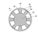
- FIG. 3 is a sectional view taken along the line III-III of FIG.
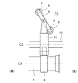
- FIG. 4 is a schematic plan view of the exhaust valve system.
- FIG. 5 is a valve lift diagram of the intake valve and the exhaust valve.
- FIG. 6 is a schematic longitudinal sectional view showing the configuration of the oil injection device.
- FIG. 7 is a diagram showing an oil injection control map.
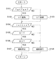
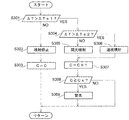
- FIG. 8 is a flowchart showing a routine of the exhaust gas temperature raising control.
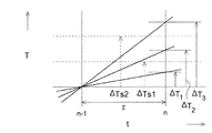
- FIG. 9 is a time chart showing how the temperature detected by the temperature sensor rises.
- FIG. 10 is a flowchart illustrating a routine of the exhaust gas temperature raising control according to the second embodiment.
- FIG. 11 is a flowchart showing a subroutine of oil injection control.
- FIG. 1 schematically shows an internal combustion engine (engine) according to the first embodiment.
- the engine 1 is a vehicle diesel engine, and the vehicle is a large vehicle such as a truck.
- the vehicle may be a small vehicle such as a passenger car, or the engine may be a gasoline engine.
- the engine is an in-line four-cylinder engine, and # 1 to # 4 cylinders are arranged in order from the front of the engine.
- the engine 1 has an exhaust passage 2 defined by an exhaust pipe or the like and through which the exhaust gas G flows.
- an oxidation catalyst (DOC) 91, a filter (DPF) 92, a NOx catalyst (SCR) 93, and an ammonia oxidation catalyst (ASC) 94 are provided in this order from the upstream side.
- Each of these constitutes a post-processing member for performing the post-emission processing.
- an addition valve 95 for adding urea water is provided.
- An exhaust gas temperature sensor 96 for detecting the temperature of the exhaust gas flowing into the DOC 91 is provided upstream of the DOC 91.
- the DOC 91 oxidizes and purifies unburned components (hydrocarbon HC and carbon monoxide CO) in the exhaust gas, and heats and raises the temperature of the exhaust gas by the reaction heat at this time. NO is oxidized to NO 2 .
- the DPF 92 is composed of a so-called continuous regeneration type DPF with a catalyst, and captures particulate matter (PM) contained in exhaust gas and continuously burns and removes the captured PM.
- the SCR 93 is a selective reduction type NOx catalyst, and reduces NOx in exhaust gas using ammonia derived from urea water from the addition valve 95 as a reducing agent.
- the ASC 94 oxidizes and purifies excess ammonia discharged from the SCR 93.
- the engine 1 has an intake camshaft 3 for opening and closing an intake valve, and an exhaust camshaft 4 for opening and closing an exhaust valve.
- the exhaust camshaft 4 is provided with a variable mechanism 5 for changing the valve timing of the exhaust valve. Note that a similar variable mechanism may be provided on the intake camshaft 3.
- FIGS. 2 and 4 For convenience, one end (the left side in FIGS. 2 and 4) in the direction (axial direction) of the center axis C1 of the exhaust camshaft 4 will be referred to as a front, and the other end (the right side in FIGS. 2 and 4) as a rear.
- These front-rear directions correspond to the front-rear directions of the engine and the vehicle (the engine is placed vertically). However, they do not necessarily have to match.
- the # 1 to # 4 cylinders are arranged in order from the front, and FIGS. 2 and 4 show the configuration around the rearmost # 4 cylinder.
- a cam 8 for opening the exhaust valve 7 against the urging force of the valve spring 6 is fixed to the exhaust camshaft 4.
- Two exhaust valves 7 are provided for each cylinder, and a valve bridge 9 is bridged between these two exhaust valves 7.
- the cam 8 opens and closes two exhaust valves 7 simultaneously via a rocker arm 11 rotatably supported by a rocker shaft 10 and a valve bridge 9.
- C2 indicates the central axis of the rocker shaft 10.
- the exhaust camshaft 4 is supported between the lower cam carrier 12 and the upper cylinder head 13 so as to be rotatable in the radial direction.
- the exhaust camshaft 4 is provided with flanges 14 and 15 for positioning the exhaust camshaft 4 in the thrust direction with the cam carrier 12 and the cylinder head 13 interposed therebetween in the axial direction.
- the rear end of the exhaust camshaft 4 located behind the cam carrier 12 and the cylinder head 13 is rotatably accommodated in the housing 30 of the variable mechanism 5.
- a final gear 16 of a power transmission mechanism that transmits power from the crankshaft is engaged with an input gear 17 provided in the housing 30.
- the exhaust camshaft 4 receives a rotational driving force from the crankshaft through the input gear 17.
- the variable mechanism 5 is configured to continuously and continuously change the valve timing of the exhaust valve 7 between the most advanced position S1 and the most retarded position S2 as shown in FIG.
- the valve timing includes both an opening timing at which the exhaust valve 7 starts opening and a closing timing at which the exhaust valve 7 ends closing.
- a crank angle period during which the exhaust valve 7 is open (that is, the valve lift amount VL is larger than zero) is referred to as a working angle.
- the opening timing and the closing timing are continuously changed by the variable width X.
- variable mechanism 5 has a rotor 31 formed at the rear end of the exhaust camshaft 4 and the above-described housing 30 that houses the rotor 31 so as to be relatively rotatable.
- a plurality of (four) housing vanes 32 projecting inward in the radial direction are formed at equal intervals in the circumferential direction in the housing 30, and a hydraulic chamber 33 is formed between the housing vanes 32.
- a plurality of (four) rotor vanes 34 projecting radially outward are formed at equal intervals in the circumferential direction on the rotor 31, and these rotor vanes 34 partition each hydraulic chamber 33 before and after in the camshaft rotation direction R.
- the advanced chamber 35 is located rearward in the rotational direction
- the retard chamber 36 is located forward in the rotational direction.
- an advanced oil passage 37 communicating with the advance chamber 35 and a retard oil passage 38 communicated with the retard chamber 36 are formed inside the exhaust camshaft 4.
- An advancing oil supply hole 39 for connecting the advancing oil passage 37 to the oil gallery 41 is formed inside the cylinder head 13.
- a retarding oil supply hole 40 for communicating the retarding oil passage 38 with the oil gallery 41 is formed.
- the oil gallery 41 is a space formed inside the cylinder block as an oil reservoir for storing high-pressure oil (pressure oil as a pressure fluid).
- the advance chamber 35, the advance oil passage 37, and the advance oil supply hole 39 constitute an advance flow path. Further, the retard chamber 36, the retard oil passage 38, and the retard oil supply hole 40 constitute a retard passage.
- a hydraulic circuit is configured to control the hydraulic pressure supplied to the advance channel and the retard channel, and thus to control the hydraulic pressure supplied to the variable mechanism 5.
- the hydraulic circuit includes an oil gallery 41 as a hydraulic pressure source, an oil pan 43 as an oil tank for storing oil at normal pressure, an oil gallery 41, an oil pan 43, an advance oil supply hole 39, and a retard oil.
- the OCV 42 is constituted by a solenoid valve.
- the oil pump described later sucks the oil in the oil pan 43 and discharges the oil toward the oil gallery 41.
- an oil pump may be used directly as a hydraulic pressure source.
- an electronic control unit (referred to as ECU) 100 is provided as a control unit, circuit element or controller.
- the ECU 100 controls the entire engine, and includes a CPU having an arithmetic function, ROM and RAM serving as storage media, input / output ports, and storage devices other than the ROM and RAM.
- the ECU 100 is configured to control the OCV 42 and control the valve timing of the variable mechanism 5 and thus the exhaust valve 7.
- the addition valve 95 and the exhaust gas temperature sensor 96 are connected to the ECU 100.
- the ECU 100 controls the addition valve 95 and receives a detection signal from the exhaust gas temperature sensor 96.
- the variable mechanism 5 is controlled as follows.
- the OCV 42 is switched to the advanced position by the ECU 100, and the high-pressure oil stored in the oil gallery 41 passes through the advanced oil supply hole 39 and the advanced oil passage 37 to the advanced chamber 35 in this order. be introduced.
- the high-pressure oil in the retard chamber 36 is discharged to the oil pan 43 through the retard oil passage 38 and the retard oil supply hole 40 in this order.
- the oil pressure in the advance chamber 35 becomes higher than the oil pressure in the retard chamber 36, and the rotor 31 and thus the exhaust camshaft 4 are advanced.
- the OCV 42 is switched to the retard position by the ECU 100, and the high-pressure oil in the advance chamber 35 passes through the advance oil passage 37 and the advance oil supply hole 39 to the oil pan 43 in this order. Is discharged.
- the high-pressure oil stored in the oil gallery 41 is introduced into the retard chamber 36 through the retard oil supply hole 40 and the retard oil passage 38 in this order. Then, the oil pressure in the retard chamber 36 becomes higher than the oil pressure in the advance chamber 35, and the rotor 31 and thus the exhaust camshaft 4 are retarded with respect to the housing 30.
- the OCV 42 is switched to the holding position by the ECU 100, and the supply and discharge of the high-pressure oil to the advance chamber 35 and the retard chamber 36 are stopped.
- the rotor 31 and the exhaust camshaft 4 are held at a relative position with respect to the housing 30 such that the oil pressure in the advance chamber 35 and the oil pressure in the retard chamber 36 become equal, and the valve timing is maintained at a constant timing. Will be retained.
- an oil injection device for injecting oil toward the piston is also provided.
- the configuration will be described.
- FIG. 6 shows only two intermediate cylinders of all four cylinders, that is, only the # 2 and # 3 cylinders.
- a piston 55 is housed inside the cylinder bore 52 so as to be able to move up and down.
- a connecting rod 57 is rotatably attached to the piston 55 via a piston pin 56.
- the figure shows a state where the pistons 55 of the # 2 and # 3 cylinders are at the position of the bottom dead center (BDC).
- BDC bottom dead center
- TDC top dead center
- a circulation path 60 extending in the circumferential direction of the piston for circulating the cooling oil, and an inlet hole 61 and an outlet hole 62 serving as an oil inlet and an outlet for the circulation path 60 are provided.
- the inlet hole 61 and the outlet hole 62 open on the back surface of the piston 55.
- cooling oil is injected from the oil jet 63 toward the opening end of the inlet hole 61.
- the oil jet 63 is attached to the cylinder block 51 at a position below the piston 55 and is directed upward.
- the cooling oil introduced into the circulation path 60 from the inlet hole 61 exchanges heat with the piston 55 during the circulation in the circulation path 60, and cools the piston 55. After cooling, the oil is discharged from the circulation path 60 through the outlet hole 62, and is returned to an oil pan (indicated by reference numeral 43) below the figure.
- the oil jet 63 is directed to the back surface of the piston 55, and the oil injected from the oil jet 63 and not entering the inlet hole 61 hits the back surface of the piston 55 to cool the piston 55. Then, some of the oil that has hit the cylinder reaches the inner wall of the cylinder bore 52 and lubricates it.
- the oil jet 63 of each cylinder is connected to a common oil passage 65, and the oil passage 65 is connected to the oil gallery 41 via an on-off valve 66.
- the oil discharged from the oil pump 68 is stored in the oil gallery 41 in a high pressure state.
- the on-off valve 66 is controlled by the ECU 100.
- the oil pump 68 of this embodiment is a mechanical type driven to rotate by a crankshaft, but may be an electric type driven to rotate by an electric motor.
- the oil pump 68 when the oil injection by the oil jet 63 is executed, it is necessary to newly generate high-pressure oil by the oil pump 68, so that the execution of the oil injection leads to an increase in pump drive loss, and the fuel consumption is increased. It causes deterioration.
- the on-off valve 66 is formed by a two-way solenoid valve, and is opened when turned on and closed when turned off.
- the on-off valve 66 is opened by the ECU 100, the high-pressure oil in the oil gallery 41 reaches the oil jet 63 of each cylinder through the oil passage 65, and is injected from the oil jet 63 of each cylinder. That is, oil injection is performed.
- the on-off valve 66 is closed by the ECU 100, the high-pressure oil in the oil gallery 41 is not supplied to the oil jet 63 of each cylinder, and the oil injection is stopped.
- the oil injection device includes the oil jet 63 that injects oil, and the on-off valve 66 that switches between execution and stop of oil injection by the oil jet 63.
- a temperature sensor 83 for detecting a temperature is provided. Output signals of these sensors are sent to the ECU 100.
- the ECU 100 instructs the fuel injection amount, particularly the injector 58, based on the engine speed Ne and the accelerator opening Ac detected by the rotation speed sensor 81 and the accelerator opening sensor 82, respectively, according to a predetermined fuel injection amount map (not shown).
- a target fuel injection amount Q as an injection amount is calculated.
- the fuel injection amount map is set in advance through tests and the like, and is stored in the ECU 100.
- the target fuel injection amount Q is a parameter representing the engine load. However, any parameter other than the target fuel injection amount Q, such as the accelerator opening, can be adopted as this parameter.
- the engine speed Ne, the accelerator opening Ac, and the target fuel injection amount Q are used as parameters representing the engine operation state, but other parameters may be used.
- the temperature sensor 83 is installed in a partition wall between the cylinder bores 52 located in the middle part of the cylinder row. Further, the temperature sensor 83 is installed at a height position between an intermediate height position Hf that bisects the interval between the top dead center TDC and the bottom dead center BDC of the piston 5 to the bottom dead center BDC.
- the cylinder center axis is indicated by C3.
- the middle part of the cylinder row is the middle part of the cylinder row in the direction of the cylinder row formed by these four cylinders (that is, the front-back direction), and specifically, the cylinder center of the # 1 cylinder located at the forefront end. This is a position Pf at which the interval between the shaft (not shown) and the cylinder center axis (not shown) of the # 4 cylinder located at the rearmost end is bisected, or a position in the vicinity thereof.
- the partition wall between the cylinder bores 52 at this position refers to a partition wall 69 between the cylinder bores 52 of the # 2 cylinder and the # 3 cylinder adjacent to each other as shown in the figure.
- the temperature sensor 83 is installed on the bisecting position Pf, but the temperature sensor 83 may be installed slightly shifted in the front-rear direction from the bisecting position Pf.
- the temperature sensor 83 is provided in the partition wall 69 between the water jackets 54 of the # 2 cylinder and the # 3 cylinder.
- the temperature sensor 83 is inserted and attached to the sensor attachment hole 70 provided inside the partition 69, and detects the temperature of the partition 69 at the installation position.
- the temperature sensor 83 is installed at an arbitrary height between the intermediate height position Hf and the bottom dead center BDC.
- the temperature sensor 83 is installed at a height position Hg that bisects the interval between the intermediate height position Hf and the height position of the bottom dead center BDC.
- the temperature sensor 83 may be installed at a position slightly above or below the bisected height position Hg.
- the temperature sensor 83 directly detects the temperature of the partition 69 at the installation position, and the temperature of the partition 69 is correlated with the temperature of the piston 55. Therefore, the temperature sensor 83 detects a temperature correlated with the temperature of the piston 55. Based on the temperature detected by the temperature sensor 83, it is possible to detect whether or not the piston temperature is significantly increased.
- the temperature sensor 83 may detect a temperature other than the partition wall 69 correlated with the temperature of the piston 55.
- the post-processing members DOC91, DPF92, SCR93, ASC94
- the warm-up of the post-processing members is promoted, and the post-processing members are quickly moved.
- exhaust gas temperature rise control for increasing the temperature of the exhaust gas is performed.
- the purpose of the exhaust gas temperature raising control may be for another purpose, for example, for regeneration of the DPF 92, but here, as an example, a case where the purpose is to promote warm-up of the post-processing member after the cold start is described. .
- the ECU 100 controls the variable mechanism 5 to perform the exhaust gas temperature increase so that the exhaust gas temperature is increased.
- the valve timing of the valve is advanced.
- the target exhaust temperature Tgs is set to a value substantially equal to the activation start temperature, for example, about 200 ° C., so that at least the post-processing member (DOC 91) located immediately after the exhaust temperature sensor 96 can be activated.
- the exhaust valve valve timing at the normal time or the reference time is the most retarded position S2, but when the detected exhaust temperature Tg is lower than the target exhaust temperature Tgs, the exhaust valve valve timing is the most advanced position.
- the angle is advanced to S1.
- the exhaust valve opening timing near or immediately before the exhaust BDC at the most retarded position S2 becomes earlier as a result of being advanced to the most advanced position S1, and becomes near the middle part of the expansion stroke. Then, the exhaust gas whose temperature has increased by the amount corresponding to the earlier opening timing of the exhaust valve is discharged from the combustion chamber to the exhaust passage 2, and the exhaust gas temperature is raised. Then, it is possible to promote warm-up of the post-processing member.
- the oil injection device when the exhaust valve timing is advanced when the exhaust gas temperature rises, the oil injection device is simultaneously controlled to stop the oil injection. Specifically, the on / off valve 66 is controlled to be turned off, that is, closed, to stop the oil injection from the oil jet 63.
- the oil injection increases pump drive loss due to the oil pump 68, and deteriorates fuel efficiency.
- the oil injection is stopped when the exhaust valve timing is advanced, so that it is possible to suppress the deterioration of fuel efficiency as compared with the case where the oil injection is not stopped.
- ECU 100 is configured to control oil injection from oil jet 13 based on the operating state of the engine. That is, an oil injection control map as shown in FIG. 7 is stored in the ECU 100 in advance, and the ECU 100 basically executes or stops oil injection according to the oil injection control map.
- the oil injection control map is a map for determining execution / stop of oil injection using the engine speed Ne and the fuel injection amount (specifically, the target fuel injection amount Q) that define the engine operating state as input parameters.
- the entire operation region of the engine is divided into a stop permission region R1 for permitting the stop of the oil injection and a stop prohibition region R2 for not permitting (ie, prohibiting) the stop of the oil injection.
- the stop permission region R1 is a region on a lower rotation side and a lower load side than the stop prohibition region R2, the piston temperature does not rise so much, and in some cases, even if the oil injection is stopped, there is no problem such as piston seizure. Such an area.
- the stop prohibition region R2 is a region in which oil injection is indispensable to prevent piston seizure or the like because the piston temperature reaches a high temperature.
- a stop region R3 in which the oil injection is stopped when the exhaust valve timing is advanced when the temperature of the exhaust gas is increased is set in the stop permission region R1.
- the stop area R3 is included in the stop permission area R1.
- the stop region R3 is set at the lowest rotation speed and the lowest load side of the stop permission region R1, and is a region most suitable for stopping the oil injection such that even if the oil injection is stopped, there is no risk of piston seizure or the like. Is set to
- the stop region R3 is a region most suitable for stopping the oil injection.
- the illustrated routine is repeatedly executed by the ECU 100 every predetermined calculation cycle.
- step S101 the ECU 100 determines whether the exhaust gas temperature Tg detected by the exhaust gas temperature sensor 96 is lower than the target exhaust gas temperature Tgs. If YES, the ECU 100 proceeds to step S102 to advance the exhaust valve timing (VT) to the most advanced position S1. Thereby, the exhaust gas temperature is substantially increased.
- VT exhaust valve timing
- step S103 controls the exhaust valve timing to the reference position most retarded position S2.
- the exhaust gas temperature is not substantially increased.
- the exhaust valve timing may be advanced from the most retarded position S2 for other purposes.
- step S104 determines whether the elapsed time tc from the cold start of the engine has exceeded the predetermined time tcs.
- the cold start of the engine can be detected from the ON signal to the starter motor and the water temperature at that time, and the elapsed time tc can be measured by a timer or the like in the ECU 100.
- the predetermined time tcs is set as a minimum time until a sufficient oil film is formed so as not to cause lubrication failure on the sliding portion.
- step S108 If the elapsed time tc has not exceeded the predetermined time tcs, the ECU 100 proceeds to step S108, turns on the on-off valve 66, and executes oil injection. At this time, it is preferable to continuously turn on the on-off valve 16 to execute the continuous oil injection.
- step S105 determines whether the current engine operation state is in the stop permission region R1. If it is not in the stop permission area R1, this means that it is in the stop prohibition area R2, so the ECU 100 proceeds to step S108 and executes the oil injection without stopping.
- step S106 determines whether the current engine operation state is in the stop region R3.
- the engine output is larger than when the engine is in the stop region R3, and there is a possibility that the merit of suppressing the fuel consumption deterioration due to the stop of the oil injection may not be enjoyed so much. Therefore, in this case, the process proceeds to step S108, and the oil injection is executed without stopping. In this case, the oil injection may be stopped according to other requirements.
- step S107 turns off the on-off valve 6, and stops the oil injection.
- the stop of the oil injection can be efficiently executed.
- step S108 is also omitted.
- the present embodiment is a main difference from the first embodiment in that the oil injection is controlled based on the temperature detected by the temperature sensor 83.
- the stop permission area R1 is an area where there is no problem even if oil injection is stopped in some cases.
- the piston temperature may rise significantly even in the stop permission region R1 due to some cause such as a change in the engine operation state or a failure. Even in this case, it is desirable to avoid stopping the oil injection because there is a risk of piston seizure.
- the temperature sensor 83 indirectly detects or predicts whether or not there is a remarkable rise in the piston temperature. If the rise is predicted, the stop permission region R1 is set. Also executes oil injection to prevent the seizure of the piston 55 from occurring.
- the ECU 100 sequentially calculates the amount of increase ⁇ T of the detected temperature T of the temperature sensor 83 per predetermined time ⁇ at each predetermined time ⁇ .
- the predetermined time ⁇ is equal to, but may be different from, the calculation cycle of the routine of FIG. 10 described later.
- ECU 100 compares the calculated increase amount ⁇ T with a predetermined first threshold value ⁇ Ts1.
- a predetermined first threshold value ⁇ Ts1 In case the engine operating condition is in the stop permission region R1 (including the stop region R3), when the increase amount is equal to or less than the first threshold value ⁇ Ts1 as indicated by [Delta] T 1 is regarded as ECU100 is no significant increase in piston temperature , Stop the oil injection.
- ECU 100 determines that there is a significant increase in piston temperature, executes oil injection, and executes oil cooling of piston 55. Thereby, the seizure of the piston 55 can be suppressed beforehand.
- the execution method of the oil injection is changed according to the magnitude of the increase amount ⁇ T. That is, as the increase amount is indicated by [Delta] T 2, when higher than the first threshold value ⁇ Ts1 is the second threshold ⁇ Ts2 following regards ECU100 the rise of the piston temperature is mild, the rising speed of the piston temperature is relatively slow , Execute intermittent oil injection. At this time, the ECU 100 turns on and off the on-off valve 66 so that the opening and closing of the on-off valve 66 are repeated for a predetermined time.
- the execution time of the oil injection can be reduced, the pump drive loss can be reduced, and the deterioration of fuel efficiency can be suppressed as compared with the case where the continuous injection is executed. And the seizure of the piston 55 can be suppressed efficiently.
- ECU 100 may increase the piston temperature is severe, the rising speed of the piston temperature regarded as relatively fast, perform a continuous jet of oil I do. At this time, the ECU 100 keeps the on-off valve 66 turned on so that the on-off valve 66 keeps opening continuously. Thereby, the piston 55 can be cooled to the maximum, and seizure of the piston 55 can be reliably suppressed.
- the intermittent injection of oil literally means control for turning on and off the on-off valve 66 so as to repeat injection of oil from the oil jet 63 and stop of injection. Therefore, this is different from the duty control in which the on-off valve is turned on and off with a very short duty cycle so as to continuously inject oil from the oil jet while controlling the oil injection flow rate.
- a state in which the increase amount ⁇ T exceeds the first threshold value ⁇ Ts1 for a relatively long time while the engine operation state is in the stop permission region R1 is a healthy state (for convenience, abnormal state).
- the ECU 100 measures the time during which the engine operation state is in the stop permission region R1 and the increase amount ⁇ T exceeds the first threshold value Ts1, and when the measured time reaches a predetermined time or longer, The warning is executed assuming that there is a possibility that the failure has occurred.
- a warning device such as a warning light is activated.
- the user can be urged to check and maintain the vehicle, and the vehicle can be returned to a healthy state at an early stage.
- FIG. 10 shows a routine of the exhaust gas temperature raising control in the present embodiment.
- This routine is almost the same as the routine of the first embodiment shown in FIG. 8, and the same steps are denoted by changing the reference numerals to the 200's and will not be described. The only difference is that step S107 of the routine of the first embodiment is changed to step S207A.
- step S207A oil injection control is performed according to a subroutine shown in FIG.
- step S301 the ECU 100 calculates the increase amount ⁇ T of the detected temperature T by the above-described method, and compares the increase amount ⁇ T with a first threshold value ⁇ Ts1 stored in advance.
- step S302 the ECU 100 turns off the on-off valve 66 to stop the oil injection. At this time, there is no remarkable rise in the piston temperature, and there is no risk of seizure of the piston 55. Then, the count value C of the internal counter is reset to zero, the present routine ends, and the process returns to the main routine of FIG.
- step S304 the ECU 100 compares the increase amount ⁇ T with a second threshold value ⁇ Ts2 stored in advance.
- step S305 When the increase amount ⁇ T is equal to or smaller than the second threshold value ⁇ Ts2, the process proceeds to step S305, and the ECU 100 turns on and off the on-off valve 66 to execute intermittent oil injection. On the other hand, when the increase amount ⁇ T exceeds the second threshold value ⁇ Ts2, the process proceeds to step S306, and the ECU 100 continuously turns on the on-off valve 66 to execute the continuous oil injection.
- Step S307 ⁇ the ECU 100 increments the count value C of the internal counter by one in order to measure the duration of the above-described abnormal state.
- step S308 the ECU 100 compares the count value C with a predetermined threshold value Cs. When the count value C is less than the threshold value Cs, the present routine is ended and the process returns to the main routine of FIG. When the count value C is equal to or greater than the threshold value Cs, the process proceeds to step S309, and the ECU 100 determines that the duration of the abnormal state has reached a predetermined time or more, and issues a warning. Then, this routine ends, and the process returns to the main routine of FIG.
- the piston temperature is considered to have significantly increased. Anticipate and perform oil injection. Therefore, seizure of the piston 5 can be suppressed beforehand.
- the temperature sensor 83 was installed in the partition wall 69 between the cylinder bores 52 located in the middle part of the cylinder row (between the # 2 cylinder and the # 3 cylinder). For this reason, compared with the case where it is installed in the water jacket 54, the influence of the fluctuation of the cooling water is eliminated, and the temperature correlated with the piston temperature can be detected more accurately. In addition, as compared with the case where it is installed in a partition other than the middle part of the cylinder row, the effect of cooling by outside air can be reduced and the correlation temperature can be detected more accurately.
- the temperature sensor 83 was installed at a height between the intermediate height Hf and the bottom dead center BDC. Therefore, the temperature sensor 83 can detect not only the piston temperature but also a temperature that is correlated with the lubrication state between the piston 55 and the inner wall of the cylinder bore 52, and the execution and stop of the oil injection are performed in consideration of the lubrication state. Can be determined appropriately.
- the temperature sensor 83 can detect a temperature that is also correlated with the lubrication state between the piston 55 and the inner wall of the cylinder bore 52, and the execution and stop of the oil injection can be appropriately determined in consideration of the lubrication state.
- the temperature sensor 83 is provided at (i) a position in the partition wall 69 between the cylinder bores 52 located at an intermediate portion of the cylinder row, and (ii) a height position from the intermediate height position Hf to the bottom dead center BDC. Of these, it is possible to install at least one. In the present embodiment, it is installed at the positions (i) and (ii), but it may be installed at the position only (i) or only the position (ii).
- the partition between the cylinder bores located in the middle of the cylinder row is set in the same way as in the present embodiment.
- the partition between the # 3 cylinder and the # 4 cylinder is the partition.
- the partition closest to the center of the cylinder row is the partition.
- the closest partition wall between the # 1 cylinder and the # 2 cylinder or the partition wall between the # 2 cylinder and the # 3 cylinder is It is a partition.
- the advance of the exhaust valve timing at the time of exhaust gas temperature rise is not limited to the advance from the most retarded position S2 to the most advanced position S1, but is advanced from any position to any position. It may be.
- the exhaust gas temperature sensor 96 can be installed not only on the upstream side of the DOC 91 but also at any position in the exhaust passage 2. However, it is preferable to be installed upstream or immediately before the post-processing member to be warmed up.
- a plurality of temperature sensors 83 may be provided, and oil injection control may be performed based on the average value of the detected temperatures.
- the warning method may be changed according to whether the rising amount ⁇ T exceeds the second threshold value ⁇ Ts2. Further, if the rise amount ⁇ T does not exceed the second threshold value ⁇ Ts2, the predetermined time (Cs) until the warning is executed is lengthened, and if the rise amount ⁇ T exceeds the second threshold value ⁇ Ts2, a warning is issued. May be shortened until the execution of.
- the present invention has an effect of suppressing deterioration of fuel consumption when exhaust gas temperature is raised by advancing the valve timing of an exhaust valve, and includes an exhaust gas heating device and an exhaust gas heating control method for an internal combustion engine.
Landscapes
- Engineering & Computer Science (AREA)
- Mechanical Engineering (AREA)
- General Engineering & Computer Science (AREA)
- Chemical & Material Sciences (AREA)
- Combustion & Propulsion (AREA)
- Output Control And Ontrol Of Special Type Engine (AREA)
- Lubrication Of Internal Combustion Engines (AREA)
Abstract
内燃機関の排気昇温装置は、排気弁のバルブタイミングを変更する可変機構と、ピストン55に向けてオイルを噴射するオイル噴射装置63,66と、排気昇温時に、可変機構を制御して排気弁のバルブタイミングを進角すると共に、オイル噴射装置を制御してオイル噴射を停止するように構成された制御ユニット100と、を備える。
Description
本開示は内燃機関の排気昇温装置および排気昇温制御方法に関する。
例えば車両用の内燃機関において、冷間始動後における触媒の暖機促進等を目的として、排気ガスの温度を上昇させる排気昇温を行うことがある。例えば、排気弁のバルブタイミングを変更する可変機構を備えた内燃機関では、排気昇温時に排気弁のバルブタイミングが進角させられる。これにより、進角前の状態に比べ排気弁の開タイミングが早くなるので、その分、排気ガスの温度を上昇することができ、触媒の暖機を促進することが可能になる。
しかし、排気弁のバルブタイミングを進角させると、排気弁の開タイミングが、排気下死点に対しより早いタイミングに設定される。すると、燃料の燃焼によって発生した熱エネルギが十分にピストン仕事に変換される前に、排気弁が開いてしまい、内燃機関の燃費が悪化する問題がある。
こうした燃費悪化はある程度避けられないが、理想的には、燃費悪化代をできるだけ少なくできる改善策が望まれる。
そこで本開示は、かかる事情に鑑みて創案され、その目的は、排気弁のバルブタイミングを進角して排気昇温を行う場合に、燃費悪化を抑制することが可能な内燃機関の排気昇温装置を提供することにある。
本開示の一の態様によれば、
排気弁のバルブタイミングを変更する可変機構と、
ピストンに向けてオイルを噴射するオイル噴射装置と、
排気昇温時に、前記可変機構を制御して前記排気弁のバルブタイミングを進角すると共に、前記オイル噴射装置を制御してオイル噴射を停止するように構成された制御ユニットと、
を備えたことを特徴とする内燃機関の排気昇温装置が提供される。
排気弁のバルブタイミングを変更する可変機構と、
ピストンに向けてオイルを噴射するオイル噴射装置と、
排気昇温時に、前記可変機構を制御して前記排気弁のバルブタイミングを進角すると共に、前記オイル噴射装置を制御してオイル噴射を停止するように構成された制御ユニットと、
を備えたことを特徴とする内燃機関の排気昇温装置が提供される。
好ましくは、前記制御ユニットは、前記内燃機関の冷間始動時からの経過時間が所定時間を超えているときにオイル噴射を停止する。なお、前記制御ユニットは、前記内燃機関の前記冷間始動時からの前記経過時間が前記所定時間未満のときにオイル噴射を実行してもよい。
好ましくは、前記制御ユニットは、前記内燃機関の運転状態が所定の停止領域にあるときにオイル噴射を停止する。なお、前記制御ユニットは、前記内燃機関の運転状態が所定の停止禁止領域にあるときにオイル噴射を実行してもよい。
好ましくは、前記排気昇温装置は、前記ピストンの温度に相関する温度を検出する温度センサをさらに備え、
前記制御ユニットは、前記温度センサの検出温度の所定時間当たりの上昇量が所定の閾値以下であるときにオイル噴射を停止する。なお、前記制御ユニットは、前記温度センサの前記検出温度の前記所定時間当たりの上昇量が、前記所定の閾値よりも高い所定の第2閾値以下であるときにオイルの間欠噴射を実行してもよい。前記制御ユニットは、前記温度センサの前記検出温度の前記所定時間当たりの上昇量が、前記所定の第2閾値を超えているときに、オイルの連続噴射を実行してもよい。
前記制御ユニットは、前記温度センサの検出温度の所定時間当たりの上昇量が所定の閾値以下であるときにオイル噴射を停止する。なお、前記制御ユニットは、前記温度センサの前記検出温度の前記所定時間当たりの上昇量が、前記所定の閾値よりも高い所定の第2閾値以下であるときにオイルの間欠噴射を実行してもよい。前記制御ユニットは、前記温度センサの前記検出温度の前記所定時間当たりの上昇量が、前記所定の第2閾値を超えているときに、オイルの連続噴射を実行してもよい。
本開示の他の態様によれば、排気弁のバルブタイミングを変更する可変機構とピストンに向けてオイルを噴射するオイル噴射装置とを備えた内燃機関と、制御ユニットと、を備えた車両の排気昇温制御方法であって、前記方法は前記制御ユニットに、排気昇温時に、前記可変機構を制御して前記排気弁のバルブタイミングを進角させると共に、前記オイル噴射装置を制御してオイル噴射を停止させる、ことを含む、排気昇温制御方法が提供される。
本開示によれば、排気弁のバルブタイミングを進角して排気昇温を行う場合に、燃費悪化を抑制することができる。
以下、添付図面を参照して本開示の実施形態を説明する。なお本開示は以下の実施形態に限定されない点に留意すべきである。
[第1実施形態]
図1は、第1実施形態に係る内燃機関(エンジン)を概略的に示す。エンジン1は車両用ディーゼルエンジンであり、車両はトラック等の大型車両である。しかしながら、車両およびエンジンの種類、形式、用途等に特に限定はなく、例えば車両は乗用車等の小型車両であってもよいし、エンジンはガソリンエンジンであってもよい。本実施形態の場合、エンジンは直列4気筒エンジンであり、エンジンの前方から順に#1気筒~#4気筒が配置される。
図1は、第1実施形態に係る内燃機関(エンジン)を概略的に示す。エンジン1は車両用ディーゼルエンジンであり、車両はトラック等の大型車両である。しかしながら、車両およびエンジンの種類、形式、用途等に特に限定はなく、例えば車両は乗用車等の小型車両であってもよいし、エンジンはガソリンエンジンであってもよい。本実施形態の場合、エンジンは直列4気筒エンジンであり、エンジンの前方から順に#1気筒~#4気筒が配置される。
エンジン1は、排気管等により画成されて排気ガスGが流される排気通路2を有する。排気通路2には、上流側から順に、酸化触媒(DOC)91、フィルタ(DPF)92、NOx触媒(SCR)93およびアンモニア酸化触媒(ASC)94が設けられる。これらはそれぞれ排気後処理を実行する後処理部材をなす。SCR93の直前には尿素水を添加する添加弁95が設けられる。またDOC91の上流側には、DOC91に流入する排気ガスの温度を検出するための排気温センサ96が設けられる。
周知のように、DOC91は、排気ガス中の未燃成分(炭化水素HCおよび一酸化炭素CO)を酸化して浄化すると共に、このときの反応熱で排気ガスを加熱昇温し、また排気中のNOをNO2に酸化する。DPF92は、所謂連続再生式の触媒付きDPFからなり、排気中に含まれる粒子状物質(PM)を捕集すると共に、捕集したPMを連続的に燃焼除去する。SCR93は、選択還元型NOx触媒であり、添加弁95からの尿素水に由来するアンモニアを還元剤として排気中のNOxを還元する。ASC94は、SCR93から排出された余剰アンモニアを酸化して浄化する。
なお、後処理部材の数や種類を変更した変形例も可能である。
エンジン1は、吸気弁を開閉するための吸気カムシャフト3と、排気弁を開閉するための排気カムシャフト4とを有する。また排気カムシャフト4には、排気弁のバルブタイミングを変更する可変機構5が付設される。なお、同様の可変機構が吸気カムシャフト3に設けられてもよい。
以下、図2~図4を参照して、排気カムシャフト4および可変機構5を含む排気動弁系の構成を説明する。便宜上、排気カムシャフト4の中心軸C1の方向(軸方向)における一端側(図2,図4の左側)を前、他端側(図2,図4の右側)を後とする。これら前後方向は、エンジンおよび車両の前後方向と一致する(エンジンは縦置きされる)。但し必ずしも一致しなくてもよい。前方から順に#1気筒~#4気筒が配置され、図2,図4は最後端の#4気筒周辺の構成を示す。
図4に示すように、排気カムシャフト4には、バルブスプリング6の付勢力に抗じて排気弁7を開弁するカム8が固設されている。排気弁7は1気筒当たりに二つ設けられ、これら二つの排気弁7にバルブブリッジ9が掛け渡される。カム8は、ロッカーシャフト10に回動可能に支持されたロッカーアーム11と、バルブブリッジ9とを介して、二つの排気弁7を同時に開閉するようになっている。C2はロッカーシャフト10の中心軸を示す。
図2に示すように、排気カムシャフト4は、下側のカムキャリア12と、上側のシリンダヘッド13との間に挟まれてラジアル方向に回転可能に支持される。排気カムシャフト4には、これらカムキャリア12およびシリンダヘッド13を軸方向に挟んで排気カムシャフト4をスラスト方向に位置決めするフランジ14,15が設けられる。
カムキャリア12およびシリンダヘッド13の後方に位置する排気カムシャフト4の後端部は、可変機構5のハウジング30内に回転可能に収容されている。クランクシャフトから動力を伝達する動力伝達機構の最終ギヤ16が、ハウジング30に設けられた入力ギヤ17に噛合されている。排気カムシャフト4は、この入力ギヤ17を通じて、クランクシャフトからの回転駆動力を受ける。
可変機構5は、排気弁7のバルブタイミングを、図5に示すような最進角位置S1と最遅角位置S2との間で無段階かつ連続的に変化させるように構成されている。ここでバルブタイミングには、排気弁7が開弁を開始する開タイミングと、排気弁7が閉弁を終了する閉タイミングとの両方が含まれる。また排気弁7が開弁している(すなわちバルブリフト量VLがゼロより大きくなっている)クランク角期間を作用角という。本実施形態では、作用角Δθと最大バルブリフト量VLmaxとが一定とされる一方で、開タイミングと閉タイミングが可変幅Xだけ連続的に変化させられる。
図2および図3に示すように、可変機構5は、排気カムシャフト4の後端部に形成されたロータ31と、ロータ31を相対回転可能に収容する前述のハウジング30とを有する。
図3に示すように、ハウジング30には半径方向内側に突出する複数(4つ)のハウジングベーン32が周方向等間隔で形成され、これらハウジングベーン32の間に油圧室33が形成される。他方、ロータ31には半径方向外側に突出する複数(4つ)のロータベーン34が周方向等間隔で形成され、これらロータベーン34は各油圧室33を、カムシャフト回転方向Rの前後に仕切る。仕切られた油圧室33のうち、回転方向後方に位置するのは進角室35であり、回転方向前方に位置するのは遅角室36である。
図2に示すように、排気カムシャフト4の内部には、進角室35に連通された進角用オイル通路37と、遅角室36に連通された遅角用オイル通路38とが形成される。シリンダヘッド13の内部には、進角用オイル通路37をオイルギャラリ41に連通させるための進角用オイル供給穴39が形成される。カムキャリア12の内部には、遅角用オイル通路38をオイルギャラリ41に連通させるための遅角用オイル供給穴40が形成される。オイルギャラリ41は、シリンダブロックの内部に形成され高圧オイル(圧力流体としての圧油)を貯留するオイル溜めとしての空間である。
進角室35、進角用オイル通路37および進角用オイル供給穴39は進角用流路を構成する。また遅角室36、遅角用オイル通路38および遅角用オイル供給穴40は遅角用流路を構成する。これら進角用流路および遅角用流路に供給される油圧を制御し、ひいては可変機構5に供給される油圧を制御するため、油圧回路が構成される。
油圧回路は、油圧源としてのオイルギャラリ41と、オイルを常圧で貯留するオイルタンクとしてのオイルパン43と、これらオイルギャラリ41、オイルパン43、進角用オイル供給穴39および遅角用オイル供給穴40の連通状態を切り替える切替バルブ(OCVという)42とを含む。OCV42はソレノイドバルブにより構成される。
なお、後述するオイルポンプがオイルパン43のオイルを吸引し、オイルギャラリ41に向けて吐出する。オイルギャラリ41の代わりに、オイルポンプを直接的に油圧源として用いてもよい。
他方、制御ユニット、回路要素(circuitry)もしくはコントローラとしての電子制御ユニット(ECUという)100が設けられる。ECU100はエンジン全体の制御を司るもので、演算機能を有するCPU、記憶媒体であるROMおよびRAM、入出力ポート、ならびにROMおよびRAM以外の記憶装置等を含む。ECU100は、OCV42を制御し、可変機構5ひいては排気弁7のバルブタイミングを制御するように構成されている。
また図1に示すように、添加弁95および排気温センサ96がECU100に接続され、ECU100は、添加弁95を制御すると共に排気温センサ96から検出信号を受け取る。
可変機構5は次のように制御される。バルブタイミングの進角時、OCV42がECU100により進角位置に切り替えられ、オイルギャラリ41に貯留された高圧オイルが進角用オイル供給穴39、進角用オイル通路37を順に経て進角室35に導入される。また遅角室36内の高圧オイルは、遅角用オイル通路38および遅角用オイル供給穴40を順に経てオイルパン43に排出される。すると、進角室35内の油圧が遅角室36内の油圧より高くなり、ロータ31ひいては排気カムシャフト4が、進角動作させられる。
他方、バルブタイミングの遅角時には、OCV42がECU100により遅角位置に切り替えられ、進角室35内の高圧オイルが進角用オイル通路37、進角用オイル供給穴39を順に経てオイルパン43に排出される。またオイルギャラリ41に貯留された高圧オイルは、遅角用オイル供給穴40、遅角用オイル通路38を順に経て遅角室36に導入される。すると、遅角室36内の油圧が進角室35内の油圧より高くなり、ロータ31ひいては排気カムシャフト4が、ハウジング30に対し遅角動作させられる。
他方、バルブタイミングの保持時には、OCV42がECU100により保持位置に切り替えられ、進角室35および遅角室36に対する高圧オイルの供給および排出は停止される。これにより、ロータ31および排気カムシャフト4は、進角室35内の油圧と遅角室36内の油圧とが等しくなるような、ハウジング30に対する相対位置に保持され、バルブタイミングは一定のタイミングに保持される。
さらに本実施形態においては、ピストンに向けてオイルを噴射するオイル噴射装置も設けられる。以下、その構成について説明する。
図6に示すように、シリンダブロック51には各気筒のシリンダボア52が前後方向に等間隔で立設され、各シリンダボア52の上端開口部はシリンダヘッド13により閉止される。各シリンダボア52の外周側を取り囲むよう、シリンダブロック51の内部には、冷却水が循環されるウォータジャケット54が形成される。なお図6には全4気筒のうちの中間の2気筒、すなわち#2および#3気筒のみを示す。
シリンダボア52の内部にはピストン55が昇降可能に収容される。ピストン55にはピストンピン56を介してコンロッド57が回転可能に取り付けられる。図は#2,#3気筒のピストン55が下死点(BDC)の位置にあるときの状態を示す。他方、ピストン55が上死点(TDC)付近の位置にあるとき、シリンダヘッド13に取り付けられたインジェクタ58から、ピストン55の頂面部のキャビティ59内に向かって、燃料が噴射される。
ピストン55の内部には、冷却用オイルを循環させるピストン周方向に延びた循環路60と、循環路60に対するオイル入口および出口となる入口孔61および出口孔62とが設けられる。入口孔61および出口孔62はピストン55の裏面部に開口している。基本的には、この入口孔61の開口端に向かって、冷却用オイルがオイルジェット63から噴射される。オイルジェット63は、ピストン55よりも下方の位置でシリンダブロック51に取り付けられ、上向きに指向されている。
入口孔61から循環路60に導入された冷却用オイルは、循環路60を循環する過程でピストン55と熱交換し、ピストン55を冷却する。そして冷却を終えたオイルは、出口孔62を通じて循環路60から排出され、図外下方のオイルパン(符号43で略示)に戻される。
なお、オイルジェット63はピストン55の裏面部に向けられ、オイルジェット63から噴射され入口孔61に入らなかったオイルは、ピストン55の裏面部に当たってピストン55を冷却する。そして当たった後の一部のオイルは、シリンダボア52の内壁に到達し、これを潤滑する。
各気筒のオイルジェット63は共通のオイル通路65に接続され、このオイル通路65は開閉弁66を介してオイルギャラリ41に接続される。オイルギャラリ41には、オイルポンプ68から吐出されたオイルが高圧状態で貯留される。開閉弁66はECU100により制御される。
本実施形態のオイルポンプ68は、クランクシャフトにより回転駆動される機械式のものであるが、電気モータにより回転駆動される電動式のものであっても構わない。いずれにしても、オイルジェット63によるオイル噴射が実行されると、その分の高圧オイルをオイルポンプ68により新たに生成する必要があるから、オイル噴射の実行はポンプ駆動損失の増大に繋がり、燃費悪化の原因となる。
開閉弁66は二方電磁弁により形成され、オンのとき開、オフのとき閉となる。ECU100により開閉弁66が開とされると、オイルギャラリ41内の高圧オイルがオイル通路65を通じて各気筒のオイルジェット63に至り、各気筒のオイルジェット63から噴射される。すなわちオイル噴射が実行される。他方、ECU100により開閉弁66が閉とされると、オイルギャラリ41内の高圧オイルは各気筒のオイルジェット63に供給されなくなり、オイル噴射は停止される。
このようにオイル噴射装置は、オイルを噴射するオイルジェット63と、オイルジェット63によるオイル噴射の実行と停止を切り替える開閉弁66とを備える。
エンジンの回転速度、具体的には単位時間当たりの回転数Ne(rpm)を検出するための回転速度センサ81と、アクセル開度Acを検出するためのアクセル開度センサ82と、シリンダブロック51の温度を検出する温度センサ83とが設けられる。これらセンサの出力信号はECU100に送られる。
ECU100は、回転速度センサ81およびアクセル開度センサ82によりそれぞれ検出されたエンジン回転数Neおよびアクセル開度Acに基づき、図示しない所定の燃料噴射量マップに従って、燃料噴射量、特にインジェクタ58への指示噴射量としての目標燃料噴射量Qを算出する。燃料噴射量マップは予め試験等を通じて設定され、ECU100に記憶されている。目標燃料噴射量Qは、エンジン負荷を表すパラメータである。但しこのパラメータについては、目標燃料噴射量Q以外にもアクセル開度等の任意のパラメータを採用できる。ここではエンジン運転状態を表すパラメータとしてエンジン回転数Ne、アクセル開度Acおよび目標燃料噴射量Qを用いたが、他のパラメータを用いてもよい。
温度センサ83は、気筒列の中間部に位置するシリンダボア52間の隔壁内に設置される。また温度センサ83は、ピストン5の上死点TDCおよび下死点BDC間の間隔を二等分する中間高さ位置Hfから、下死点BDCまでの間の高さ位置に設置される。
本実施形態の場合、#1~#4気筒の4つの気筒が等間隔で配置されている。図中、シリンダ中心軸をC3で示す。気筒列の中間部とは、これら4つの気筒で形成される気筒列の方向(すなわち前後方向)における気筒列の中間部であり、具体的には、最前端に位置する#1気筒のシリンダ中心軸(図示せず)と、最後端に位置する#4気筒のシリンダ中心軸(図示せず)との間隔を二等分する位置Pf、またはその付近の位置である。この位置のシリンダボア52間の隔壁とは、本実施形態では、図示するような互いに隣り合う#2気筒および#3気筒のシリンダボア52間の隔壁69のことをいう。本実施形態では、二等分位置Pf上に温度センサ83が設置されているが、二等分位置Pfから前後方向に多少ずらして温度センサ83を設置してもよい。なお温度センサ83は、#2気筒および#3気筒のウォータジャケット54の間の隔壁69内に設置される。
温度センサ83は、隔壁69の内部に設けられたセンサ取付孔70に挿入して取り付けられ、設置位置の隔壁69の温度を検出する。
また温度センサ83は、中間高さ位置Hfから下死点BDCまでの間の任意の高さ位置に設置される。本実施形態では、中間高さ位置Hfと下死点BDCの高さ位置との間隔を二等分する高さ位置Hgに温度センサ83が設置される。しかしながら、その二等分高さ位置Hgよりも上方または下方に若干位置をずらして温度センサ83を設置してもよい。
温度センサ83は、直接的には、その設置位置における隔壁69の温度を検出するが、その隔壁69の温度は、ピストン55の温度に相関する。従って温度センサ83は、ピストン55の温度に相関する温度を検出するものである。この温度センサ83の検出温度に基づいて、ピストン温度の著しい上昇があるか否かを検出することができる。
なお、温度センサ83は、ピストン55の温度に相関する隔壁69以外の温度を検出してもよい。
次に、本実施形態の制御を詳細に説明する。
本実施形態では、冷間始動後で前述の後処理部材(DOC91、DPF92、SCR93、ASC94)が未だ活性化していないようなときに、後処理部材の暖機を促進し、後処理部材を早期に活性化させるため、排気ガスの温度を上昇させる排気昇温制御を行う。なお、排気昇温制御の目的は他の目的、例えばDPF92の再生のためであってもよいが、ここでは一例として、冷間始動後の後処理部材の暖機促進を目的とする場合を述べる。
具体的にはECU100は、排気温センサ96により検出された排気温度すなわち検出排気温度Tgが、所定の目標排気温度Tgsより低いとき、排気昇温を実行すべく、可変機構5を制御して排気弁のバルブタイミングを進角させる。目標排気温度Tgsは、少なくとも排気温センサ96の直後に位置する後処理部材(DOC91)が活性化できるよう、その活性開始温度に略等しい値、例えば約200℃に設定される。
図5に示すように、通常時もしくは基準時の排気弁バルブタイミングは最遅角位置S2であるが、検出排気温度Tgが目標排気温度Tgsより低いときは、排気弁バルブタイミングが最進角位置S1まで進角させられる。
すると、最遅角位置S2で排気BDCの近傍もしくは直前であった排気弁開タイミングは、最進角位置S1に進角された結果、より早くなり、膨張行程の中間部付近になる。すると、排気弁開タイミングが早まった分だけ温度が高くなった排気ガスが、燃焼室から排気通路2に排出され、排気昇温が実行される。そして後処理部材の暖機を促進することが可能になる。
しかし、このように排気弁開タイミングを早めると、燃料の燃焼によって発生した熱エネルギが十分にピストン仕事に変換される前に、すなわち、ピストンが排気BDC付近まで十分に押し下げられる前に、排気弁が開いてしまう。よって熱エネルギのピストン仕事への変換効率が低下し、エンジンの燃費が悪化する問題がある。
こうした燃費悪化はある程度避けられないが、理想的には、このときの燃費悪化代をできるだけ少なくすることが望まれる。
そこで本実施形態では、排気昇温時に排気弁バルブタイミングを進角させるとき、同時に、オイル噴射装置を制御してオイル噴射を停止する。具体的には、開閉弁66をオフすなわち閉に制御してオイルジェット63からのオイル噴射を停止させる。
前述したように、かかるオイル噴射は、オイルポンプ68によるポンプ駆動損失を増大させ、燃費を悪化させる。本実施形態によれば、排気弁バルブタイミング進角時にオイル噴射を停止するので、停止しない場合に比べ、燃費悪化を抑制することが可能となる。
ここで、本実施形態におけるオイル噴射制御の基本について説明する。ECU100は、エンジンの運転状態に基づいて、オイルジェット13からのオイル噴射を制御するように構成されている。すなわち、ECU100には、図7に示すようなオイル噴射制御マップが予め記憶されており、ECU100は、基本的にこのオイル噴射制御マップに従って、オイル噴射を実行または停止する。
オイル噴射制御マップは、エンジン運転状態を規定するエンジン回転数Neと燃料噴射量(具体的には目標燃料噴射量Q)を入力パラメータとしてオイル噴射の実行・停止を決定するためのマップである。
オイル噴射制御マップにおいては、エンジンの全運転領域が、オイル噴射の停止を許可する停止許可領域R1と、オイル噴射の停止を許可しない(すなわち禁止する)停止禁止領域R2とに二分される。停止許可領域R1は、停止禁止領域R2よりも低回転側かつ低負荷側の領域であり、ピストン温度がそれ程上昇せず、場合によってはオイル噴射を停止してもピストン焼き付き等の問題が生じないような領域である。逆に、停止禁止領域R2は、ピストン温度が高温まで達するため、ピストン焼き付き等を防止するためオイル噴射が必須となる領域である。
さらに、停止許可領域R1内には、排気昇温時に排気弁バルブタイミングが進角されるときオイル噴射が停止される停止領域R3が設定される。停止領域R3は停止許可領域R1に含まれる。停止領域R3は、停止許可領域R1のうちの最も低回転側かつ低負荷側に設定され、オイル噴射を停止してもピストン焼き付き等の虞が最もないような、オイル噴射停止に最も適した領域に設定される。
また、こうした最も低回転側かつ低負荷側の領域では、エンジン出力が低く、オイル噴射停止による燃費悪化抑制のメリットないし取り代が大きい。よってこの意味でも、停止領域R3はオイル噴射停止に最も適した領域である。
次に、図8を参照して、本実施形態における排気昇温制御のルーチンを説明する。図示するルーチンはECU100により所定の演算周期毎に繰り返し実行される。
まずステップS101において、ECU100は、排気温センサ96の検出排気温度Tgが目標排気温度Tgsより低いか否かを判断する。YESの場合、ECU100は、ステップS102に進み、排気弁バルブタイミング(VT)を最進角位置S1まで進角させる。これにより排気昇温が実質的に実行される。
他方、NOの場合、ECU100は、ステップS103に進み、排気弁バルブタイミングを基準状態の最遅角位置S2に制御する。この場合、排気昇温は実質的に実行されない。但しこの場合、他の目的により、排気弁バルブタイミングを、最遅角位置S2より進角させてもよい。
ステップS102またはS103の後、ECU100は、ステップS104に進み、エンジンの冷間始動時からの経過時間tcが所定時間tcsを超えているか否かを判断する。周知のように、エンジンの冷間始動はスタータモータへのオン信号とその時の水温等から検出でき、経過時間tcはECU100内のタイマ等で計測できる。
エンジンの冷間始動時から短時間しか経過していないような場合には、シリンダボア52の内壁とピストン5(これに装着された図示しないピストンリングを含む)との摺動部にまだ十分な油膜が形成されていない。このときにオイル噴射を停止すると、当該摺動部に潤滑不良が起こる可能性がある。従ってそのようなときにはオイル噴射を停止せず、摺動部における潤滑不良を未然に防止している。この観点から所定時間tcsは、摺動部に潤滑不良を生じさせない程の十分な油膜が形成されるまでの最小時間として設定されている。
経過時間tcが所定時間tcsを超えていない場合、ECU100は、ステップS108に進み、開閉弁66をオンしてオイル噴射を実行する。このとき、開閉弁16を連続的にオンしてオイルの連続噴射を実行するのが好ましい。
他方、経過時間tcが所定時間tcsを超えている場合、ECU100は、ステップS105に進み、現在のエンジン運転状態が停止許可領域R1にあるか否かを判断する。停止許可領域R1にない場合、これは停止禁止領域R2にあることを意味するから、ECU100は、ステップS108に進み、オイル噴射を停止せず、それを実行する。
他方、停止許可領域R1にある場合、ECU100は、ステップS106に進み、現在のエンジン運転状態が停止領域R3にあるか否かを判断する。停止領域R3にない場合、エンジン出力が停止領域R3にあるときよりも大きく、オイル噴射停止による燃費悪化抑制のメリットをそれ程多く享受できない可能性がある。従ってこの場合はステップS108に進み、オイル噴射を停止せず、それを実行する。なおこの場合、他の要件によってオイル噴射を停止してもよい。
他方、停止領域R3にある場合、ECU100は、ステップS107に進み、開閉弁6オフしてオイル噴射を停止する。これにより、排気弁バルブタイミング進角による燃費悪化を抑制することが可能となる。また、オイル噴射停止による燃費悪化抑制のメリットを多く享受できる場合に限ってオイル噴射を停止するので、オイル噴射停止を効率的に実行することが可能となる。
本実施形態の変形例として、ステップS104,S105,S106の少なくとも一つを省略することが考えられる。これらの全てを省略した場合、ステップS108も省略される。
[第2実施形態]
次に、本開示の第2実施形態を説明する。なお前記第1実施形態と同様の部分については説明を割愛し、以下、第1実施形態との相違点を主に説明する。
次に、本開示の第2実施形態を説明する。なお前記第1実施形態と同様の部分については説明を割愛し、以下、第1実施形態との相違点を主に説明する。
本実施形態は、温度センサ83の検出温度にも基づいてオイル噴射を制御する点が、第1実施形態との主な相違点である。
前述したように、停止許可領域R1は、場合によってはオイル噴射を停止しても問題がない領域である。しかし、エンジン運転状態の変化や故障等の何等かの原因により、停止許可領域R1であってもピストン温度が著しく上昇する場合がある。この場合にも依然としてオイル噴射を停止することは、ピストン焼き付きの虞があるため、回避するのが望ましい。
そこで本実施形態では、ピストン温度の著しい上昇があるか否かを温度センサ83によって間接的に検出し、あるいは予想し、その上昇があると予想される場合には、停止許可領域R1であってもオイル噴射を実行し、ピストン55の焼き付きを未然に抑止するようにしている。
図9に示すように、ECU100は、温度センサ83の検出温度Tの所定時間τ当たりの上昇量ΔTを、その所定時間τ毎に逐次的に算出する。所定時間τは言い換えれば演算周期であり、例えばτ=1(s)である。所定時間τは、後述する図10のルーチンの演算周期と等しいが、異なっていてもよい。
今回の演算時期の検出温度をTn、前回の演算時期の検出温度をTn-1とすると、今回の演算時期の上昇量ΔTnは式:ΔTn=Tn-Tn-1から算出される。このようにしてECU100は、検出温度Tの上昇速度である所定時間τ当たりの上昇量ΔTを、所定時間τ毎に逐次的に算出する。
次いでECU100は、算出された上昇量ΔTを所定の第1閾値ΔTs1と比較する。エンジン運転状態が停止許可領域R1(停止領域R3を含む)にある場合において、上昇量がΔT1で示すように第1閾値ΔTs1以下であるときには、ECU100は、ピストン温度の著しい上昇がないとみなし、オイル噴射を停止する。
しかしながら、上昇量がΔT2で示すように第1閾値ΔTs1を超えたときには、ECU100は、ピストン温度の著しい上昇があるとみなし、オイル噴射を実行し、ピストン55のオイル冷却を実行する。これによりピストン55の焼き付きを未然に抑止することができる。
ここで本実施形態では、上昇量ΔTが第1閾値ΔTs1を超えてオイル噴射を実行する場合に、上昇量ΔTの大きさに応じてオイル噴射の実行方法を変更している。すなわち、上昇量がΔT2で示すように、第1閾値ΔTs1より高い第2閾値ΔTs2以下であるときには、ECU100は、ピストン温度の上昇が軽度であり、ピストン温度の上昇速度が比較的遅いとみなし、オイルの間欠噴射を実行する。このときECU100は、開閉弁66の開弁と閉弁を所定時間ずつ繰り返すよう、開閉弁66をオンオフする。これにより連続噴射を実行する場合に比べ、オイル噴射の実行時間を減らし、ポンプ駆動損失を低減して燃費悪化を抑制できる。そして効率的にピストン55の焼き付きを抑止することができる。
他方、上昇量がΔT3で示すように、第2閾値ΔTs2より高いときには、ECU100は、ピストン温度の上昇が重度であり、ピストン温度の上昇速度が比較的早いとみなし、オイルの連続噴射を実行する。このときECU100は、開閉弁66が連続的に開弁し続けるよう、開閉弁66をオンし続ける。これによりピストン55を最大限冷却することができ、ピストン55の焼き付きを確実に抑止することができる。
なお、オイルの間欠噴射とは、文字通り、オイルジェット63からのオイルの噴射と噴射停止を繰り返すよう開閉弁66をオンオフする制御をいう。従ってこれは、オイル噴射流量を制御しつつ、オイルジェットから連続的にオイルを噴射するよう、開閉弁を極短時間のデューティ周期でオンオフするディーティ制御とは異なる。
ところで、エンジン運転状態が停止許可領域R1にあるのに、上昇量ΔTが比較的長時間に亘って第1閾値ΔTs1を超えている状態というのは、健全な状態とは言い難い(便宜上、異常状態という)。そこで本実施形態においてECU100は、エンジン運転状態が停止許可領域R1にありかつ上昇量ΔTが第1閾値Ts1を超えている時間を計測し、この計測した時間が所定時間以上に達したときには、何等かの故障が発生している可能性があるとみなして、警告を実行する。具体的には、警告灯等の警告装置を起動させる。これにより、車両の点検整備をユーザに促すことができ、早期に健全な状態に復帰させることができる。
図10には、本実施形態における排気昇温制御のルーチンを示す。このルーチンは図8に示した第1実施形態のルーチンとほぼ同様であり、同様のステップについては符号を200番台に変更して図示するに止め、説明を省略する。異なるのは、第1実施形態のルーチンのステップS107がステップS207Aに変更されている点のみである。
ステップS207Aでは、図11に示すサブルーチンに従ってオイル噴射制御が実行される。
このサブルーチンにおいて、ECU100は、ステップS301において、前述の方法により検出温度Tの上昇量ΔTを算出し、上昇量ΔTを、予め記憶してある第1閾値ΔTs1と比較する。
上昇量ΔTが第1閾値ΔTs1以下であるときには、ステップS302に進み、ECU100は、開閉弁66をオフにしてオイル噴射を停止する。このときにはピストン温度の著しい上昇がなく、ピストン55の焼き付きの虞が無いからである。そして内部カウンタのカウント値Cをゼロにリセットして、本ルーチンを終了し、図10のメインルーチンに戻る。
他方、上昇量ΔTが第1閾値ΔTs1を超えているときには、ステップS304に進み、ECU100は上昇量ΔTを、予め記憶してある第2閾値ΔTs2と比較する。
上昇量ΔTが第2閾値ΔTs2以下であるときには、ステップS305に進み、ECU100は、開閉弁66をオンオフしてオイルの間欠噴射を実行する。他方、上昇量ΔTが第2閾値ΔTs2を超えているときには、ステップS306に進み、ECU100は、開閉弁66を連続的にオンしてオイルの連続噴射を実行する。
その後、ステップS307に進み、ECU100は、前述の異常状態の継続時間を計測すべく、内部カウンタのカウント値Cを1だけカウントアップする。
そしてステップS308に進み、ECU100は、カウント値Cを所定の閾値Csと比較する。カウント値Cが閾値Cs未満であるときには、本ルーチンを終了して図10のメインルーチンに戻る。カウント値Cが閾値Cs以上であるときには、ステップS309に進み、ECU100は、異常状態の継続時間が所定時間以上に達したとみなし、警告を実行する。そして本ルーチンを終了し、図10のメインルーチンに戻る。
このように本実施形態によれば、エンジン運転状態が停止許可領域R1、特に停止領域R3にあっても、上昇量ΔTが第1閾値ΔTs1を超えたときには、ピストン温度が著しく上昇していると予想し、オイル噴射を実行する。従ってピストン5の焼き付きを未然に抑止することが可能である。
また、温度センサ83の設置位置にも特徴がある。まず温度センサ83を、気筒列の中間部(#2気筒と#3気筒の間)に位置するシリンダボア52間の隔壁69内に設置した。このため、ウォータジャケット54内に設置する場合に比べ、冷却水の変動の影響を無くし、ピストン温度に相関する温度をより正確に検出できる。また、気筒列の中間部以外の隔壁内に設置する場合に比べ、外気による冷却の影響を減らし、同相関温度をより正確に検出できる。
また温度センサ83を、中間高さ位置Hfから下死点BDCまでの間の高さ位置に設置した。このため、ピストン温度のみでなく、ピストン55とシリンダボア52内壁との間の潤滑状態にも相関した温度を温度センサ83により検出することができ、同潤滑状態も考慮してオイル噴射の実行および停止を適切に判断できる。
シリンダボア52間の隔壁の温度が著しく上昇する場合、次の三つの原因が考えられる。
(1)ピストン55とシリンダボア52内壁との間の潤滑油不足による摩擦増加。(2)異常燃焼によるピストン温度の上昇。(3)冷却水回路の不調(詰まり、オーバーヒート等)によるウォータジャケット54の冷却水循環不良。
(1)ピストン55とシリンダボア52内壁との間の潤滑油不足による摩擦増加。(2)異常燃焼によるピストン温度の上昇。(3)冷却水回路の不調(詰まり、オーバーヒート等)によるウォータジャケット54の冷却水循環不良。
ここで(2)の影響は、ピストン55の下死点BDC側よりもむしろ上死点TDC側で顕著に現れる。また(3)の影響も同様である。ウォータジャケット54内の冷却水温度が、下死点BDC側よりもむしろ上死点TDC側で高くなりがちだからである。
一方、隔壁温度は、ピストン55の下部のスカート部がシリンダボア52内壁に摩擦摺動することで上昇する。オイル噴射停止により、その摺動部へのオイル供給が無くなると、(1)が生じ易い。また(1)の影響は、上死点TDC側よりもむしろ下死点BDC側で顕著に現れる。
従って、温度センサ83を中間高さ位置Hfから下死点BDCまでの間の高さ位置に設置することで、(2)および(3)の影響を排除または抑制すると共に、(1)の影響を積極的に反映させて隔壁温度を検出できる。よって、ピストン55とシリンダボア52内壁との間の潤滑状態にも相関した温度を温度センサ83により検出することができ、同潤滑状態も考慮してオイル噴射の実行および停止を適切に判断できる。
なお、温度センサ83は、(i)気筒列の中間部に位置するシリンダボア52間の隔壁69内の位置、および(ii)中間高さ位置Hfから下死点BDCまでの間の高さ位置のうち、少なくとも一方に設置することが可能である。本実施形態では(i)および(ii)の位置に設置したが、(i)のみの位置、または(ii)のみの位置に設置してもよい。
ここで、気筒列の中間部に位置するシリンダボア間の隔壁は、気筒列の気筒数が偶数の場合には、本実施形態と同様の考え方で当該隔壁が設定される。例えば直列6気筒エンジンの場合には、#3気筒と#4気筒の間の隔壁が当該隔壁である。V4、V8、V12エンジンのV字を構成する2つのバンクのいずれか一方(以下、片バンク)についても同様である。これに対し、気筒列の気筒数が奇数の場合には、気筒列の中間に最も近い隔壁が当該隔壁である。例えば直列3気筒エンジンでは、気筒列の中間が#2気筒の中心なので、これに最も近い#1気筒と#2気筒の間の隔壁、または#2気筒と#3気筒の間の隔壁が、当該隔壁である。直列5気筒エンジン、またはV6、V10エンジンの片バンクについても同様である。
以上、本開示の実施形態を詳細に述べたが、本開示の実施形態は他にも様々考えられる。
(1)例えば、排気昇温時の排気弁バルブタイミングの進角は、最遅角位置S2から最進角位置S1までの進角に限定されず、任意の位置から任意の位置までの進角であってよい。
(2)排気温センサ96は、DOC91の上流側に限らず、排気通路2の任意の位置に設置可能である。但し、暖機促進対象となる後処理部材の上流側ないし直前に設置されるのが好ましい。
(3)ピストン55の循環路60を省略してもよい。
(4)温度センサ83を複数設置し、これら検出温度の平均値等に基づいてオイル噴射制御を行ってもよい。
(5)上昇量ΔTが第1閾値ΔTs1を超えている場合、上昇量ΔTが第2閾値ΔTs2を超えているか否かに応じて、警告方法を変更してもよい。また、上昇量ΔTが第2閾値ΔTs2を超えてない場合には、警告を実行するまでの所定時間(Cs)を長くし、上昇量ΔTが第2閾値ΔTs2を超えている場合には、警告を実行するまでの所定時間を短くしてもよい。
本開示の実施形態は前述の実施形態のみに限らず、特許請求の範囲によって規定される本開示の思想に包含されるあらゆる変形例や応用例、均等物が本開示に含まれる。従って本開示は、限定的に解釈されるべきではなく、本開示の思想の範囲内に帰属する他の任意の技術にも適用することが可能である。
本出願は、2018年6月29日付で出願された日本国特許出願(特願2018-124486)に基づくものであり、その内容はここに参照として取り込まれる。
本発明は、排気弁のバルブタイミングを進角して排気昇温を行う場合に、燃費悪化を抑制することができるという効果を有し、内燃機関の排気昇温装置および排気昇温制御方法等に有用である。
5 可変機構
7 排気弁
55 ピストン
63 オイルジェット
66 開閉弁
83 温度センサ
100 電子制御ユニット(ECU)
tc 経過時間
R3 停止領域
7 排気弁
55 ピストン
63 オイルジェット
66 開閉弁
83 温度センサ
100 電子制御ユニット(ECU)
tc 経過時間
R3 停止領域
Claims (9)
- 排気弁のバルブタイミングを変更する可変機構と、
ピストンに向けてオイルを噴射するオイル噴射装置と、
排気昇温時に、前記可変機構を制御して前記排気弁のバルブタイミングを進角すると共に、前記オイル噴射装置を制御してオイル噴射を停止するように構成された制御ユニットと、
を備えたことを特徴とする内燃機関の排気昇温装置。 - 前記制御ユニットは、前記内燃機関の冷間始動時からの経過時間が所定時間を超えているときにオイル噴射を停止する
請求項1に記載の内燃機関の排気昇温装置。 - 前記制御ユニットは、前記内燃機関の前記冷間始動時からの前記経過時間が前記所定時間未満のときにオイル噴射を実行する
請求項2に記載の内燃機関の排気昇温装置。 - 前記制御ユニットは、前記内燃機関の運転状態が所定の停止領域にあるときにオイル噴射を停止する
請求項1~3のいずれか一項に記載の内燃機関の排気昇温装置。 - 前記制御ユニットは、前記内燃機関の運転状態が所定の停止禁止領域にあるときにオイル噴射を実行する、
請求項4に記載の内燃機関の排気昇温装置。 - 前記ピストンの温度に相関する温度を検出する温度センサをさらに備え、
前記制御ユニットは、前記温度センサの検出温度の所定時間当たりの上昇量が所定の閾値以下であるときにオイル噴射を停止する
請求項1~5のいずれか一項に記載の内燃機関の排気昇温装置。 - 前記制御ユニットは、前記温度センサの前記検出温度の前記所定時間当たりの上昇量が、前記所定の閾値よりも高い所定の第2閾値以下であるときにオイルの間欠噴射を実行する、
請求項6に記載の内燃機関の排気昇温装置。 - 前記制御ユニットは、前記温度センサの前記検出温度の前記所定時間当たりの上昇量が、前記所定の第2閾値を超えているときに、オイルの連続噴射を実行する、
請求項7に記載の内燃機関の排気昇温装置。 - 排気弁のバルブタイミングを変更する可変機構とピストンに向けてオイルを噴射するオイル噴射装置とを備えた内燃機関と、制御ユニットと、を備えた車両の排気昇温制御方法であって、前記方法は前記制御ユニットに、
排気昇温時に、前記可変機構を制御して前記排気弁のバルブタイミングを進角させると共に、前記オイル噴射装置を制御してオイル噴射を停止させる、
ことを含む、排気昇温制御方法。
Applications Claiming Priority (2)
| Application Number | Priority Date | Filing Date | Title |
|---|---|---|---|
| JP2018124486A JP2020002899A (ja) | 2018-06-29 | 2018-06-29 | 内燃機関の排気昇温装置 |
| JP2018-124486 | 2018-06-29 |
Publications (1)
| Publication Number | Publication Date |
|---|---|
| WO2020004169A1 true WO2020004169A1 (ja) | 2020-01-02 |
Family
ID=68986624
Family Applications (1)
| Application Number | Title | Priority Date | Filing Date |
|---|---|---|---|
| PCT/JP2019/024247 Ceased WO2020004169A1 (ja) | 2018-06-29 | 2019-06-19 | 内燃機関の排気昇温装置および排気昇温制御方法 |
Country Status (2)
| Country | Link |
|---|---|
| JP (1) | JP2020002899A (ja) |
| WO (1) | WO2020004169A1 (ja) |
Citations (4)
| Publication number | Priority date | Publication date | Assignee | Title |
|---|---|---|---|---|
| JP2002221053A (ja) * | 2001-01-25 | 2002-08-09 | Mitsubishi Motors Corp | 可変バルブタイミング装置 |
| JP2014214664A (ja) * | 2013-04-25 | 2014-11-17 | 日野自動車株式会社 | ピストン冷却装置 |
| US20150184561A1 (en) * | 2012-10-04 | 2015-07-02 | Ford Global Technologies, Llc | Approach for controlling operation of oil injectors |
| JP2017198085A (ja) * | 2016-04-25 | 2017-11-02 | 三菱自動車工業株式会社 | エンジンの冷却装置 |
-
2018
- 2018-06-29 JP JP2018124486A patent/JP2020002899A/ja active Pending
-
2019
- 2019-06-19 WO PCT/JP2019/024247 patent/WO2020004169A1/ja not_active Ceased
Patent Citations (4)
| Publication number | Priority date | Publication date | Assignee | Title |
|---|---|---|---|---|
| JP2002221053A (ja) * | 2001-01-25 | 2002-08-09 | Mitsubishi Motors Corp | 可変バルブタイミング装置 |
| US20150184561A1 (en) * | 2012-10-04 | 2015-07-02 | Ford Global Technologies, Llc | Approach for controlling operation of oil injectors |
| JP2014214664A (ja) * | 2013-04-25 | 2014-11-17 | 日野自動車株式会社 | ピストン冷却装置 |
| JP2017198085A (ja) * | 2016-04-25 | 2017-11-02 | 三菱自動車工業株式会社 | エンジンの冷却装置 |
Also Published As
| Publication number | Publication date |
|---|---|
| JP2020002899A (ja) | 2020-01-09 |
Similar Documents
| Publication | Publication Date | Title |
|---|---|---|
| RU2702065C2 (ru) | Способ для двигателя (варианты) и система двигателя | |
| US8746201B2 (en) | Oil drain system bypass | |
| US9032941B2 (en) | Method for controlling exhaust gas re-circulation system in an internal combustion engine | |
| US8955473B2 (en) | Strategy for engine cold start emission reduction | |
| CN107255041B (zh) | 机油传输系统 | |
| US10927727B2 (en) | Oil circulation system of internal combustion engine | |
| EP1883745B1 (en) | Control system for supercharged internal combustion engine | |
| US20140283765A1 (en) | Engine cooling system | |
| US20130167508A1 (en) | Control device of diesel engine | |
| US20130000613A1 (en) | Method for operating an internal combustion engine | |
| JP6103261B2 (ja) | 圧縮着火式エンジンの制御装置 | |
| US20100071656A1 (en) | Valvetrain control strategies for exhaust aftertreatment devices | |
| US9228464B2 (en) | Method and device for controlling an internal combustion engine | |
| JP5565283B2 (ja) | 内燃機関の冷却装置 | |
| CN112824668B (zh) | 排气热管理 | |
| US11655738B2 (en) | GDCI engine with accelerated oil warm-up | |
| JP2020002899A (ja) | 内燃機関の排気昇温装置 | |
| US11203954B2 (en) | Pre-lubrication and skip fire operations during engine cranking | |
| CN105715330A (zh) | 操作内燃发动机的方法 | |
| JP7773659B2 (ja) | 内燃機関制御装置及び内燃機関制御方法 | |
| GB2394750A (en) | I.c. engine using disabled cylinders to pump secondary air to exhaust emission after-treatment device | |
| JP2019132205A (ja) | 内燃機関の可変動弁装置 | |
| GB2507343A (en) | A heating apparatus for an internal combustion engine | |
| JP6355452B2 (ja) | 内燃機関 | |
| US20230243315A1 (en) | Method to mitigate reverse oil flow to the combustion chamber via hybrid cylinder cutout for internal combustion engines |
Legal Events
| Date | Code | Title | Description |
|---|---|---|---|
| 121 | Ep: the epo has been informed by wipo that ep was designated in this application |
Ref document number: 19826482 Country of ref document: EP Kind code of ref document: A1 |
|
| NENP | Non-entry into the national phase |
Ref country code: DE |
|
| 122 | Ep: pct application non-entry in european phase |
Ref document number: 19826482 Country of ref document: EP Kind code of ref document: A1 |