WO2020003958A1 - 相互認証システム及び相互認証方法 - Google Patents
相互認証システム及び相互認証方法 Download PDFInfo
- Publication number
- WO2020003958A1 WO2020003958A1 PCT/JP2019/022534 JP2019022534W WO2020003958A1 WO 2020003958 A1 WO2020003958 A1 WO 2020003958A1 JP 2019022534 W JP2019022534 W JP 2019022534W WO 2020003958 A1 WO2020003958 A1 WO 2020003958A1
- Authority
- WO
- WIPO (PCT)
- Prior art keywords
- key
- master
- unit
- slave device
- storage unit
- Prior art date
- Legal status (The legal status is an assumption and is not a legal conclusion. Google has not performed a legal analysis and makes no representation as to the accuracy of the status listed.)
- Ceased
Links
Images



Classifications
-
- H—ELECTRICITY
- H04—ELECTRIC COMMUNICATION TECHNIQUE
- H04L—TRANSMISSION OF DIGITAL INFORMATION, e.g. TELEGRAPHIC COMMUNICATION
- H04L9/00—Cryptographic mechanisms or cryptographic arrangements for secret or secure communications; Network security protocols
- H04L9/14—Cryptographic mechanisms or cryptographic arrangements for secret or secure communications; Network security protocols using a plurality of keys or algorithms
- H04L9/16—Cryptographic mechanisms or cryptographic arrangements for secret or secure communications; Network security protocols using a plurality of keys or algorithms the keys or algorithms being changed during operation
-
- G—PHYSICS
- G06—COMPUTING OR CALCULATING; COUNTING
- G06F—ELECTRIC DIGITAL DATA PROCESSING
- G06F21/00—Security arrangements for protecting computers, components thereof, programs or data against unauthorised activity
- G06F21/30—Authentication, i.e. establishing the identity or authorisation of security principals
- G06F21/44—Program or device authentication
- G06F21/445—Program or device authentication by mutual authentication, e.g. between devices or programs
-
- G—PHYSICS
- G06—COMPUTING OR CALCULATING; COUNTING
- G06F—ELECTRIC DIGITAL DATA PROCESSING
- G06F21/00—Security arrangements for protecting computers, components thereof, programs or data against unauthorised activity
- G06F21/70—Protecting specific internal or peripheral components, in which the protection of a component leads to protection of the entire computer
- G06F21/71—Protecting specific internal or peripheral components, in which the protection of a component leads to protection of the entire computer to assure secure computing or processing of information
- G06F21/72—Protecting specific internal or peripheral components, in which the protection of a component leads to protection of the entire computer to assure secure computing or processing of information in cryptographic circuits
-
- G—PHYSICS
- G09—EDUCATION; CRYPTOGRAPHY; DISPLAY; ADVERTISING; SEALS
- G09C—CIPHERING OR DECIPHERING APPARATUS FOR CRYPTOGRAPHIC OR OTHER PURPOSES INVOLVING THE NEED FOR SECRECY
- G09C1/00—Apparatus or methods whereby a given sequence of signs, e.g. an intelligible text, is transformed into an unintelligible sequence of signs by transposing the signs or groups of signs or by replacing them by others according to a predetermined system
-
- H—ELECTRICITY
- H04—ELECTRIC COMMUNICATION TECHNIQUE
- H04L—TRANSMISSION OF DIGITAL INFORMATION, e.g. TELEGRAPHIC COMMUNICATION
- H04L63/00—Network architectures or network communication protocols for network security
- H04L63/08—Network architectures or network communication protocols for network security for authentication of entities
- H04L63/0869—Network architectures or network communication protocols for network security for authentication of entities for achieving mutual authentication
-
- H—ELECTRICITY
- H04—ELECTRIC COMMUNICATION TECHNIQUE
- H04L—TRANSMISSION OF DIGITAL INFORMATION, e.g. TELEGRAPHIC COMMUNICATION
- H04L9/00—Cryptographic mechanisms or cryptographic arrangements for secret or secure communications; Network security protocols
- H04L9/08—Key distribution or management, e.g. generation, sharing or updating, of cryptographic keys or passwords
- H04L9/0816—Key establishment, i.e. cryptographic processes or cryptographic protocols whereby a shared secret becomes available to two or more parties, for subsequent use
- H04L9/0819—Key transport or distribution, i.e. key establishment techniques where one party creates or otherwise obtains a secret value, and securely transfers it to the other(s)
- H04L9/0822—Key transport or distribution, i.e. key establishment techniques where one party creates or otherwise obtains a secret value, and securely transfers it to the other(s) using key encryption key
-
- H—ELECTRICITY
- H04—ELECTRIC COMMUNICATION TECHNIQUE
- H04L—TRANSMISSION OF DIGITAL INFORMATION, e.g. TELEGRAPHIC COMMUNICATION
- H04L9/00—Cryptographic mechanisms or cryptographic arrangements for secret or secure communications; Network security protocols
- H04L9/08—Key distribution or management, e.g. generation, sharing or updating, of cryptographic keys or passwords
- H04L9/0861—Generation of secret information including derivation or calculation of cryptographic keys or passwords
- H04L9/0869—Generation of secret information including derivation or calculation of cryptographic keys or passwords involving random numbers or seeds
-
- H—ELECTRICITY
- H04—ELECTRIC COMMUNICATION TECHNIQUE
- H04L—TRANSMISSION OF DIGITAL INFORMATION, e.g. TELEGRAPHIC COMMUNICATION
- H04L9/00—Cryptographic mechanisms or cryptographic arrangements for secret or secure communications; Network security protocols
- H04L9/08—Key distribution or management, e.g. generation, sharing or updating, of cryptographic keys or passwords
- H04L9/0894—Escrow, recovery or storing of secret information, e.g. secret key escrow or cryptographic key storage
-
- H—ELECTRICITY
- H04—ELECTRIC COMMUNICATION TECHNIQUE
- H04L—TRANSMISSION OF DIGITAL INFORMATION, e.g. TELEGRAPHIC COMMUNICATION
- H04L9/00—Cryptographic mechanisms or cryptographic arrangements for secret or secure communications; Network security protocols
- H04L9/32—Cryptographic mechanisms or cryptographic arrangements for secret or secure communications; Network security protocols including means for verifying the identity or authority of a user of the system or for message authentication, e.g. authorization, entity authentication, data integrity or data verification, non-repudiation, key authentication or verification of credentials
- H04L9/3271—Cryptographic mechanisms or cryptographic arrangements for secret or secure communications; Network security protocols including means for verifying the identity or authority of a user of the system or for message authentication, e.g. authorization, entity authentication, data integrity or data verification, non-repudiation, key authentication or verification of credentials using challenge-response
- H04L9/3273—Cryptographic mechanisms or cryptographic arrangements for secret or secure communications; Network security protocols including means for verifying the identity or authority of a user of the system or for message authentication, e.g. authorization, entity authentication, data integrity or data verification, non-repudiation, key authentication or verification of credentials using challenge-response for mutual authentication
-
- H—ELECTRICITY
- H04—ELECTRIC COMMUNICATION TECHNIQUE
- H04L—TRANSMISSION OF DIGITAL INFORMATION, e.g. TELEGRAPHIC COMMUNICATION
- H04L2209/00—Additional information or applications relating to cryptographic mechanisms or cryptographic arrangements for secret or secure communication H04L9/00
- H04L2209/26—Testing cryptographic entity, e.g. testing integrity of encryption key or encryption algorithm
Definitions
- the present invention relates to a mutual authentication system and a mutual authentication method, and more particularly, to a mutual authentication system and a mutual authentication method capable of mutually authenticating a master device and a slave device.
- Patent Literature 1 describes an example of such a card reader.
- the master device of the card reader includes a CPU (main control unit) that controls the magnetic head.
- the slave device is configured as an integrally formed encryption magnetic head.
- the encryption magnetic head includes a magnetic head, a demodulation IC, and a CPU (sub-control unit) that performs encryption and decryption.
- the sub-control unit stores a master key which is key data for encryption. As a result, the slave device encrypts the demodulated magnetic data and securely transmits the encrypted magnetic data to the main control unit and the host device.
- the present invention has been made in view of such a situation, and an object of the present invention is to solve the above-described problems and to provide a mutual authentication system that can safely exchange slave devices without erasing a master key.
- a mutual authentication system is a mutual authentication system including a master device and a slave device that mutually authenticate each other, wherein the master device has a temporary key that is key data used temporarily, and a key that is used for authentication.
- a storage unit that stores a master key that is data, a key confirmation unit that inquires whether the slave device stores the master key, and a response to the inquiry of the key confirmation unit, in which the slave device does not store the master key.
- a key introduction unit for encrypting the master key with the temporary key and transmitting the encrypted master key to the slave device; and a main authentication unit for mutually authenticating the slave device with the master key transmitted by the key introduction unit. Wherein the slave device stores the temporary key.
- a storage unit a key acknowledgment unit that confirms whether a master key is already stored in the storage unit in response to an inquiry from the master device, and responds to the inquiry from the master device.
- a key storage unit that decrypts the master key transmitted from the storage unit with the temporary key and stores the decrypted master key in the storage unit, and the master key stored in the storage unit by the key storage unit to establish a mutual connection with the master device.
- the mutual authentication system according to the present invention is characterized in that the master device further includes a key generation unit that generates the master key using a random number when the master device is initially activated and stores the master key in the storage unit.
- a key generation unit that generates the master key using a random number when the master device is initially activated and stores the master key in the storage unit.
- the key confirmation unit inquires at a specific timing whether the slave device stores the master key. With this configuration, it is possible to detect that an unauthorized head or the like is attached.
- the mutual authentication system according to the present invention is characterized in that a symmetric key cryptosystem is used for mutual authentication by the main authentication unit and the sub authentication unit. With such a configuration, the processing speed related to mutual authentication can be improved, and mutual authentication can be performed by an apparatus having an inexpensive control unit.
- a mutual authentication method is a mutual authentication method executed by a mutual authentication system including a master device and a slave device that mutually authenticate, wherein the master device is a temporary key that is key data used temporarily. And a storage unit that stores a master key that is key data used for authentication, the slave device includes a storage unit that stores the temporary key, and the slave device stores the master key by the master device. Inquiry, the slave device responds to the inquiry from the master device by confirming whether or not a master key is already stored in the storage unit, and the master device responds to the inquiry from the master device in response to the inquiry. If the master key is not stored And encrypting the master key with the temporary key and transmitting the encrypted master key to the slave device.
- the slave device decrypts the master key transmitted from the master device with the temporary key in response to the response and stores the master key in the storage unit. And the master key is used to perform mutual authentication between the master device and the slave device. With this configuration, the slave device can be safely replaced without erasing the master key.
- the master key of the master device is not changed, the slave device after replacement is asked whether the master key is stored, and if not, the master key is encrypted using the temporary key and transmitted to the slave device.
- FIG. 1 is a system configuration diagram of a mutual authentication system according to an embodiment of the present invention.
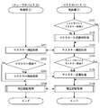
- 6 is a flowchart of a mutual authentication process according to the embodiment of the present invention.
- 3 is a sequence chart at the time of slave device exchange in the mutual authentication process shown in FIG. 2.
- 9 is a sequence chart when a conventional mutual authentication system is newly incorporated. 9 is a sequence chart in a case where a slave device is replaced (no erasure) in a conventional mutual authentication system. It is a sequence chart at the time of slave device exchange (master key deletion) of the conventional mutual authentication system.
- the card reader 1 is an ATM (Automated Teller Machine) having a card issuing function, a kiosk terminal, a transportation ticket issuing system, a point card issuing system such as a convenience store, and a retail store.
- the card reader is mounted on a member card issuing system, a gaming machine card issuance, a payment system, an entrance / exit management system, and the like (hereinafter simply abbreviated as "ATM, etc.”).
- the card reader 1 is a device that can read (read) or write (write) a card medium 2 that is a contact or non-contact IC card and / or a magnetic card provided with a magnetic stripe.
- a card medium 2 that is a contact or non-contact IC card and / or a magnetic card provided with a magnetic stripe. The detailed configuration of the card reader 1 will be described later.
- the card reader 1 is connected to a higher-level device which is a main unit for realizing each function such as ATM.
- This higher-level device includes, for example, an information processing device such as a personal computer (PC) for controlling each unit, a tablet terminal, and a mobile phone, and includes an application (Application @Program, not shown) for realizing functions such as ATM.
- a peripheral device such as a printer for printing or marking on the surface of the card medium 2, a display such as an LCD panel or an organic EL panel, a touch panel, and buttons is connected to the host device.
- the card reader 1 includes a master device 10 and a slave device 20 that mutually authenticate.
- the master device 10 is a main processing device that performs general processing as the card reader 1 and controls writing and reading of information to and from the card medium 2.
- the master device 10 is configured as, for example, various circuits on a main (main) board that controls the entire card reader 1.
- the master device 10 controls the connected slave device 20 by communication.
- the slave device 20 is an encryption magnetic head (Encrypting Head, E-Head) or the like.
- the encryption magnetic head encrypts the demodulated magnetic data and securely transmits it to the control unit 11 and the host device. Therefore, the slave device 20 realizes a function of encrypting or decrypting the information read by the magnetic head 23, encrypting or decrypting the information, and recording the information on the card medium 2 by the magnetic head 23. For this reason, the slave device 20 has, for example, a data encryption function, a decryption function, and the like for preventing fraud of data such as an ID, a password, and a password stored in the card medium 2.
- the slave device 20 of the present embodiment is configured not to execute processing unless it is controlled in accordance with a specific processing procedure.
- the master device 10 includes a control unit 11 and a storage unit 12.
- the slave device 20 includes a control unit 21, a storage unit 22, and a magnetic head 23.
- the control unit 11 includes a CPU (Central Processing Unit), an MPU (Micro Processing Unit), a GPU (Graphics Processing Unit), a DSP (Digital Signal Processor), an ASIC (Application Specific Integrated Circuit), etc., which perform processing of the entire card reader 1. Control operation means.
- CPU Central Processing Unit
- MPU Micro Processing Unit
- GPU Graphics Processing Unit
- DSP Digital Signal Processor
- ASIC Application Specific Integrated Circuit
- the storage unit 12 is a storage medium such as a random access memory (RAM) and a read only memory (ROM).
- the RAM is, for example, a volatile recording medium such as an SRAM (Static RAM) or a DRAM (Dynamic RAM), or a non-volatile recording medium such as an FeRAM (Ferroelectric Random Access Memory) or an MRAM (Magnetoresistive Random Access Memory).
- the ROM is a non-volatile recording medium such as an electrically erasable and programmable ROM (EEPROM) and a flash memory.
- the storage unit 12 stores a control program (embedded software) of the control unit 11 mounted on the master device 10.
- This control program incorporates processes such as monitoring of a sensor for detecting the card medium 2, reading and writing of the card medium 2, control of the slave device 20, and the like.
- the storage unit 12 is configured as, for example, a built-in memory of the control unit 11.
- the control unit 21 is a control arithmetic unit including a CPU, an MPU, a GPU, a DSP, an ASIC, and the like that monitors and controls the state of the slave device 20.
- the control unit 21 executes processing such as information encryption processing and authentication using encryption.
- the control unit 21 includes, for example, an accelerator (Accelerator) that executes a control program for performing various types of encryption and decryption by using a method such as AES (Advanced @ Encryption @ Standard), and exclusively executes an operation. There is also.
- the storage unit 22 is a non-transitory storage medium such as a RAM and a ROM.
- the storage unit 22 includes a volatile and a non-volatile recording medium, like the storage unit 12.
- the storage unit 22 stores a control program (embedded software) of the control unit 21 mounted on the slave device 20.
- the storage unit 22 is configured as, for example, a built-in memory of the control unit 21.
- the magnetic head 23 includes a magnetic head, an electromagnetic induction coil and terminals for reading (reading) and writing (writing) to and from the card medium 2, and a circuit for this purpose.
- the magnetic head 23 may include a sensor for detecting the card medium 2, a driving mechanism, and the like.
- FIG. 1 shows a state in which the slave device 20 is replaced (during replacement) due to wear, a failure, a change in the standard or the like after the initial activation of the master device 10.
- the slave device 20 is provided as, for example, a repair part (new) shipped from the factory.
- the control unit 11 of the master device 10 includes a key confirmation unit 100, a key introduction unit 110, a main authentication unit 120, and a key generation unit 130 as functional components.
- the storage unit 12 stores a master key 300 and a temporary key 310.
- the control unit 21 of the slave device 20 includes a key confirmation response unit 200, a key storage unit 210, and a sub-authentication unit 220 as functional components.
- the storage unit 22 stores a temporary key 310.
- the key confirmation unit 100 inquires whether the slave device 20 stores the same master key 300 as that stored in the storage unit 12. At this time, the key confirmation unit 100 inquires at a specific timing whether the slave device 20 stores the master key 300. This specific timing is, for example, a timing when the power is turned on.
- the key introduction unit 110 encrypts the master key 300 with the temporary key 310 and transmits the encrypted master key 300 to the slave device 20.
- the key introduction unit 110 can recognize the exchange of the slave device 20 or the like without erasing the master key 300, and can introduce the master key 300 generated before the exchange into the slave device 20.
- the main authentication unit 120 mutually authenticates with the slave device 20 using the master key 300 transmitted by the key introduction unit 110.
- the main authentication unit 120 performs mutual authentication with the sub-authentication unit 220.
- the mutual authentication is performed by a symmetric key cryptosystem using the master key 300.
- the key generation unit 130 generates a master key 300 using a random number when the master device 10 is initially activated, and stores the master key 300 in a nonvolatile recording medium of the storage unit 12. This initial startup is performed, for example, at the time of inspection at the time of shipment from a factory, at the time of the first power-on when installed in a customer environment (hereinafter, referred to as “at the time of shipment from a factory”).
- the key confirmation response unit 200 confirms whether or not the master key 300 is already stored in the storage unit 22 and responds to the inquiry from the master device 10.
- the key storage unit 210 decrypts the master key 300 transmitted from the master device 10 with the temporary key 310 and stores the decrypted master key 300 in the storage unit 22.
- the sub-authentication unit 220 performs mutual authentication with the master device 10 using the master key 300 stored in the storage unit 22 by the key storage unit 210.
- the sub-authentication unit 220 performs mutual authentication with the main authentication unit 120 using a symmetric key encryption method using the master key 300.
- the master key 300 is key data used for authentication.
- the master key 300 is, for example, key data of a symmetric key.
- a symmetric key a random number generated by a standard such as ANSI@X9.17 can be used so that an individual key is provided for each card reader 1 (hereinafter, referred to as “device unique”). .
- the temporary key 310 is key data used temporarily.
- the temporary key 310 is, for example, a symmetric key, and is key data common to each model.
- the temporary key 310 is also key data of a symmetric key, for example.
- control unit 11 executes the control program stored in the storage unit 12 to function as the key confirmation unit 100, the key introduction unit 110, the main authentication unit 120, and the key generation unit 130.
- the control unit 21 executes the control program stored in the storage unit 22 to function as the key confirmation response unit 200, the key storage unit 210, and the sub-authentication unit 220.
- each section of the card reader 1 described above becomes a hardware resource for executing the information processing method of the present invention.
- a part or an arbitrary combination of the above-described functional components may be configured as hardware using an IC, a programmable logic, an FPGA (Field-Programmable Gate Array), or the like.
- the master device 10 inquires whether the master key 300 is stored in the slave device 20.
- the slave device 20 responds to this inquiry by confirming whether the master key 300 is already stored in the storage unit 22.
- the master device 10 encrypts the master key 300 with the temporary key 310 and transmits the encrypted master key 300 to the slave device 20.
- the slave device 20 decrypts the master key 300 transmitted from the master device 10 with the temporary key 310 and stores the decrypted master key 300 in the storage unit 22 in response to the response.
- the master device 10 and the slave device 20 mutually authenticate with the master key 300.
- the mutual authentication process according to the present embodiment is mainly performed by the control unit 11 of the master device 10 and the control unit 21 of the slave device 20 executing the control programs stored in the storage unit 12 and the storage unit 22, respectively. And cooperate with hardware resources.
- the details of the mutual authentication process will be described step by step with reference to the flowchart of FIG.
- Step S101 First, the processing of the master device 10 will be described.
- the key generation unit 130 checks whether the master key 300 is stored in the storage unit 12 at the time of activation or the like. If the master key 300 is already stored in the storage unit 12, the key generation unit 130 determines Yes. The key generation unit 130 determines No when the master device 10 is initially activated at the time of factory shipment or the like and the master key 300 is not stored in the storage unit 12 yet. In the case of Yes, the key generation unit 130 advances the processing to step S103. In the case of No, the key generation unit 130 proceeds with the process to step S102.
- Step S102 When the master key 300 is not stored in the storage unit 12, the key generation unit 130 performs a master key generation and storage process.
- the storage unit 12 stores only the temporary key 310 as key data.
- the key generation unit 130 generates the master key 300 using the random numbers at the time of the initial startup, and stores the master key 300 in the non-volatile recording medium of the storage unit 12.
- the key generation unit 130 uses a random value generated according to a standard such as ANSI X9.17. That is, in the present embodiment, a device unique master key 300 is generated at the time of initial startup. This initial activation is performed, for example, at the time of inspection at the time of shipment from a factory, and therefore, is performed in a place with high security.
- FIG. 1 shows the configuration of the storage unit 12 in this state.
- Steps S103 and S201 the key confirmation unit 100 of the master device 10 and the key confirmation response unit 200 of the slave device 20 perform a master key confirmation process.
- the key confirmation unit 100 inquires whether the slave device 20 stores the master key 300 every time the power is turned on. At this time, the key confirmation unit 100 transmits a confirmation command or the like to the slave device 20 (timing T1).
- the key confirmation response unit 200 confirms whether the master key 300 is already stored in the storage unit 22 and responds to the inquiry from the master device 10 (timing T2). As shown in FIG. 1, when the slave device 20 is replaced, only the temporary key 310 is stored, and the master key 300 is not stored. In this case, the key confirmation response unit 200 responds that it has not been stored yet. However, for example, when the power is normally turned on, when the master key 300 is already received and stored, or when the used slave device 20 is used, the master key 300 may already be stored in the storage unit 22. obtain. As described above, when the master key 300 is already stored in the storage unit 22, the key confirmation response unit 200 responds to that effect.
- Step S104 the key introduction unit 110 of the master device 10 determines whether or not the master key 300 is stored in the slave device 20. When the key introduction unit 110 acquires a response indicating that the key is already stored from the slave device 20, the key introduction unit 110 determines Yes. If the key introduction unit 110 obtains a response indicating that it has not been stored yet, it determines that the response is No. In the case of Yes, the key introduction unit 110 proceeds with the process to step S106. In the case of No, the key introduction unit 110 proceeds with the process to step S105.
- Step S105 When the master key 300 is not stored in the slave device 20, the key introduction unit 110 performs a master key transmission process.
- the key introduction unit 110 encrypts the master key 300 with the temporary key 310 and transmits the encrypted master key 300 to the slave device 20.
- the key introduction unit 110 reads the master key 300 stored in the storage unit 12 and encrypts the master key 300 using the temporary key 310 as key data using a method such as AES. Then, the key introduction unit 110 transmits the encrypted master key 300 to the slave device 20 using a key introduction command (timing T3).
- Step S202 the processing of the slave device 20 will be described.
- the key confirmation response unit 200 branches the processing based on the result of determining whether or not the master key 300 is stored in the storage unit 22. In this determination, key confirmation response section 200 determines Yes when master key 300 is stored in storage section 22. If the master key 300 is not stored in the storage unit 22, the key confirmation response unit 200 determines No. In the case of Yes, the key confirmation response unit 200 advances the processing to Step S204. In the case of No, the key confirmation response unit 200 advances the processing to Step S203.
- Step S203 When the master key 300 is not stored in the storage unit 22, the key storage unit 210 performs a master key storage process.
- the key storage unit 210 receives, from the master device 10, the encrypted master key 300 transmitted from the master device 10 in response to the response from the key confirmation response unit 200.
- the key storage unit 210 decrypts the received encrypted master key 300 with the temporary key 310 and stores the decrypted master key 300 in the storage unit 22. If the storage is successful, the key storage unit 210 returns a message to that effect to the master device 10 (timing T4).
- Steps S106 and S204 the main authentication unit 120 of the master device 10 and the sub authentication unit 220 of the slave device 20 perform a mutual authentication process.
- the main authentication unit 120 of the master device 10 and the sub-authentication unit 220 of the slave device 20 perform mutual authentication using the master key 300.
- the main authentication unit 120 performs mutual authentication with the slave device 20 using the master key 300 stored in the storage unit 12.
- the sub-authentication unit 220 mutually authenticates with the master device 10 using the master key 300 stored in the storage unit 22 by the key storage unit 210 (timing T5, T6).
- This mutual authentication can be performed by, for example, a method described in Patent Document 2.
- the main authentication unit 120 and the sub-authentication unit 220 respectively create random numbers, encrypt them with the master key 300, transmit and receive each other, and then confirm the total value.
- the main authentication unit 120 checks the contents of the reply from the slave device and determines whether the mutual authentication has succeeded or failed (timing T7). When the authentication is successful, the main authentication unit 120 stores the fact in the storage medium of the storage unit 12.
- FIG. 4 shows an authentication sequence in which the master device and the slave device are activated first (first time) at the time of manufacture and inspection in a factory or the like and perform mutual authentication.
- the master device and the slave device each store a common temporary key.
- a master key is generated in the master device (timing T1-2).
- the master key is unique (device unique) for each card reader 1.
- the master device transmits the master key using the temporary key and causes the slave device to introduce the master key (timing T2-2).
- the slave device sends a success reply (timing T3-2).
- the master device performs mutual authentication using the master key (timing T4-2).
- the slave device sends a reply (timing T5-2).
- the master device checks the content of the reply from the slave device and determines whether the mutual authentication has succeeded or failed (timing T6-2).
- FIG. 5 shows a sequence in a case where the mutual authentication is to be performed as it is without temporarily erasing the master key when exchanging the slave device.
- the master key is device unique. Therefore, when the master device performs mutual authentication using the master key (timing T4-3), the master device determines a reply (timing T5-3) from the slave device, and the mutual authentication fails (timing T6-3). . This is because the master device determines that the master key is different because the master key after the exchange is not stored in the slave device at the time of the exchange. Further, when the slave device is replaced with a used slave device in which a master key is already stored, an illegal slave device, or the like, the mutual authentication fails and the use is prohibited.
- FIG. 6 shows a sequence at the time of slave device exchange in a state after the initial mutual authentication of FIG. 4 is performed in a typical card reader.
- a procedure for erasing the master key first is required before mutual authentication (timing T0-4). Thereafter, mutual authentication is performed in the same procedure as in FIG. 4 described above (timings T1-4 to T6-4).
- timing T0-4 a procedure for erasing the master key first is required before mutual authentication
- mutual authentication is performed in the same procedure as in FIG. 4 described above (timings T1-4 to T6-4).
- timings T1-4 to T6-4 As described above, when exchanging the slave device, which is a security product compatible with the encryption function, it was necessary to temporarily erase the master key for mutual authentication.
- erasing the master key as described above, there is a security concern, so that the master key must be erased in a secure environment (such as a security room).
- the card reader 1 is a mutual authentication system including a master device 10 and a slave device 20 for mutually authenticating each other.
- a storage unit 12 that stores a temporary key 310 that is data and a master key 300 that is key data used for authentication, and a key that inquires whether the slave device 20 stores the same master key 300 that is stored in the storage unit 12
- the key introduction unit 110 encrypts the master key 300 with the temporary key 310 and transmits the encrypted master key 300 to the slave device 20.
- the master key 300 transmitted by the key introduction unit 110 A main authentication unit 120 for performing mutual authentication with the slave device 20.
- the slave device 20 stores the temporary key 310 in the storage unit 22, and stores the master key in the storage unit 22 in response to an inquiry from the master device 10.
- a key acknowledgment unit 200 for checking whether or not the key 300 has already been stored, and in response to the response from the key acknowledgment unit 200, the master key 300 transmitted from the master device 10 is decrypted by the temporary key 310 and the storage unit 22 is used.
- a sub-authentication unit 220 for mutually authenticating with the master device 10 using the master key 300 stored in the storage unit 22 by the key storage unit 210.
- the card reader 1 does not change the master key 300, confirms the presence or absence of the master key 300 in the slave device 20 after the exchange, and introduces the master key 300 using the temporary key 310 if there is no such change.
- the master device 10 can introduce the master key 300 to the slave device 20 without erasing the master key 300, and can succeed in mutual authentication.
- the slave device 20 such as a cryptographic magnetic head, which requires high security, can be exchanged safely, and the security can be improved more than before without securing a high security state or location.
- the card reader 1 of the present embodiment can perform mutual authentication with high security even when there is no such a secure environment, and can reduce labor and cost. Further, the service person can directly replace and operate the encryption magnetic head or the like at a repair site such as an ATM, thereby reducing maintenance labor and cost.
- the card reader 1 further includes a key generation unit 130 that generates a master key 300 using a random number when the master device 10 is initially activated and stores the master key 300 in the storage unit 12.
- a key generation unit 130 that generates a master key 300 using a random number when the master device 10 is initially activated and stores the master key 300 in the storage unit 12.
- the card reader 1 is characterized in that the key confirmation unit 100 inquires at a specific timing whether the slave device 20 stores the master key 300.
- the master device 10 inquires whether the slave device 20 stores the master key 300 at a specific timing such as when the power is turned on. Thus, it is possible to detect that an unauthorized head or the like is attached.
- the card reader 1 is characterized in that a symmetric key cryptosystem is used for mutual authentication by the main authentication unit 120 and the sub authentication unit 220.
- a symmetric key cryptosystem is used for mutual authentication by the main authentication unit 120 and the sub authentication unit 220.
- the configuration using the card reader 1 including the master device 10 and the slave device 20 has been described as an example of the mutual authentication system.
- the mutual authentication system according to another embodiment of the present invention can be configured as a mutual authentication system that performs mutual authentication between a card reader and a higher-level device.
- the number of slave devices 20 is not limited to one, but may be plural.
- a configuration in which an encryption IC block is used as the slave device 20 is also possible.
- the security product may include, for example, a card printer, a card issuing device, other card-related devices, and a main body of an ATM or the like. Further, it is also possible to configure a mutual authentication system including various information processing apparatuses such as a mobile terminal such as a smartphone, a personal computer (PC), a home appliance, and an automobile as a master device or a slave device. With such a configuration, mutual authentication corresponding to various configurations can be performed.
- the master key 300 may be stored in the storage unit 12 by transmitting it from a higher-level device or by introducing key data unique to a device at the time of manufacture. With this configuration, it is also possible to manage the master key 300 stored for each device.
Landscapes
- Engineering & Computer Science (AREA)
- Computer Security & Cryptography (AREA)
- Computer Networks & Wireless Communication (AREA)
- Signal Processing (AREA)
- Theoretical Computer Science (AREA)
- Computer Hardware Design (AREA)
- Physics & Mathematics (AREA)
- General Engineering & Computer Science (AREA)
- General Physics & Mathematics (AREA)
- Software Systems (AREA)
- Mathematical Physics (AREA)
- Computing Systems (AREA)
- Storage Device Security (AREA)
Abstract
スレーブデバイスの交換時にマスタキーを消去しなくてもよい相互認証システムを提供する。記憶部12は、一時的に用いられる鍵データであるテンポラリキー310、及び認証に用いられる鍵データであるマスタキー300を格納する。記憶部22は、テンポラリキー310を格納する。鍵確認部100は、マスタキー300をスレーブデバイス20が格納しているか問い合わせる。鍵確認応答部200は、マスタデバイス10からの問い合わせに対して、マスタキー300が記憶部22に既に格納されているか確認して応答する。鍵導入部110は、マスタキー300をテンポラリキー310にて暗号化して、スレーブデバイス20に送信する。鍵格納部210は、暗号化されたマスタキー300をテンポラリキー310で復号化して記憶部22に格納する。主認証部120及び副認証部220は、このマスタキー300にて相互認証する。
Description
本発明は、相互認証システム及び相互認証方法に係り、特にマスタデバイスとスレーブデバイスとの間で相互認証可能な相互認証システム及び相互認証方法に関する。
従来から、本体側基板(マスタデバイス)と、ヘッド側基板(スレーブデバイス)とを備えるカードリーダが存在する。
特許文献1には、このようなカードリーダの一例が記載されている。このカードリーダのマスタデバイスは、磁気ヘッドを制御するCPU(主制御部)を備える。スレーブデバイスは、一体的に形成された暗号磁気ヘッドとして構成される。この暗号磁気ヘッドは、磁気ヘッド、復調用IC、及び暗号化並びに復号化を行うCPU(副制御部)を備える。副制御部は、暗号化のための鍵データであるマスタキーを格納する。これにより、スレーブデバイスは、復調した磁気データを暗号化して、安全に主制御部及び上位装置に送信する。
特許文献1には、このようなカードリーダの一例が記載されている。このカードリーダのマスタデバイスは、磁気ヘッドを制御するCPU(主制御部)を備える。スレーブデバイスは、一体的に形成された暗号磁気ヘッドとして構成される。この暗号磁気ヘッドは、磁気ヘッド、復調用IC、及び暗号化並びに復号化を行うCPU(副制御部)を備える。副制御部は、暗号化のための鍵データであるマスタキーを格納する。これにより、スレーブデバイスは、復調した磁気データを暗号化して、安全に主制御部及び上位装置に送信する。
一方、複数のデバイス間で暗号の相互認証を行う相互認証システムが存在する。たとえば、このような相互認証を行うシステムが、特許文献2に記載されている。
ここで、特許文献1に記載されたような典型的なカードリーダでも、マスタデバイスとスレーブデバイスとで、相互認証を行うものが存在した。
このようなカードリーダでは、スレーブデバイスを取り換える際(交換時)に、安全(セキュリティ)上の要求から、マスタキーをいったん消去する必要があった。しかし、マスタキーを消去すること自体に、セキュリティ上の懸念があった。
このようなカードリーダでは、スレーブデバイスを取り換える際(交換時)に、安全(セキュリティ)上の要求から、マスタキーをいったん消去する必要があった。しかし、マスタキーを消去すること自体に、セキュリティ上の懸念があった。
本発明は、このような状況に鑑みてなされたものであり、上述の問題を解消し、マスタキーを消去しなくても、安全にスレーブデバイスを交換可能とする相互認証システムを提供することを目的とする。
本発明の相互認証システムは、相互に認証するマスタデバイスとスレーブデバイスとを備える相互認証システムであって、前記マスタデバイスは、一時的に用いられる鍵データであるテンポラリキー、及び認証に用いられる鍵データであるマスタキーを格納する記憶部と、前記マスタキーを前記スレーブデバイスが格納しているか問い合わせる鍵確認部と、前記鍵確認部の問い合わせの応答において、前記スレーブデバイスが前記マスタキーを格納していない場合、前記テンポラリキーにて、前記マスタキーを暗号化して前記スレーブデバイスに送信する鍵導入部と、前記鍵導入部により送信された前記マスタキーにて、前記スレーブデバイスとの間で相互認証する主認証部とを備え、前記スレーブデバイスは、前記テンポラリキーを格納する記憶部と、前記マスタデバイスからの問い合わせに対して、前記記憶部にマスタキーが既に格納されているか確認して応答する鍵確認応答部と、前記鍵確認応答部の応答に対して、前記マスタデバイスから送信された前記マスタキーを前記テンポラリキーで復号化して前記記憶部に格納する鍵格納部と、前記鍵格納部により前記記憶部に格納された前記マスタキーにて、前記マスタデバイスとの間で相互認証する副認証部とを備えることを特徴とする。
このように構成することで、マスタキーを消去しなくても、安全にスレーブデバイスを交換することができる。
このように構成することで、マスタキーを消去しなくても、安全にスレーブデバイスを交換することができる。
本発明の相互認証システムは、前記マスタデバイスは、初期起動した際に、乱数を用いて前記マスタキーを生成し、前記記憶部に格納する鍵生成部を更に備えることを特徴とする。
このように構成することで、工場出荷時等において、マスタデバイスを初期起動した際に、デバイスユニークな鍵データを安全に生成することができる。
このように構成することで、工場出荷時等において、マスタデバイスを初期起動した際に、デバイスユニークな鍵データを安全に生成することができる。
本発明の相互認証システムは、前記鍵確認部は、特定タイミングで、前記スレーブデバイスが前記マスタキーを格納しているか問い合わせることを特徴とする。
このように構成することで、不正ヘッド等が取り付けられたことを、検知することができる。
このように構成することで、不正ヘッド等が取り付けられたことを、検知することができる。
本発明の相互認証システムは、前記主認証部及び前記副認証部による相互認証には、対称鍵暗号方式を用いることを特徴とする。
このように構成することで、相互認証に係る処理速度を向上させることができ、安価な制御部をもつ装置で相互認証ができる。
このように構成することで、相互認証に係る処理速度を向上させることができ、安価な制御部をもつ装置で相互認証ができる。
本発明の相互認証方法は、相互に認証するマスタデバイスとスレーブデバイスとを備える相互認証システムにより実行される相互認証方法であって、前記マスタデバイスは、一時的に用いられる鍵データであるテンポラリキー、及び認証に用いられる鍵データであるマスタキーを格納する記憶部を備え、前記スレーブデバイスは、前記テンポラリキーを格納する記憶部を備え、前記マスタデバイスにより、前記マスタキーを前記スレーブデバイスが格納しているか問い合わせ、前記スレーブデバイスにより、前記マスタデバイスからの問い合わせに対して、前記記憶部にマスタキーが既に格納されているか確認して応答し、前記マスタデバイスにより、問い合わせの応答において、前記スレーブデバイスが前記マスタキーを格納していない場合、前記テンポラリキーにて、前記マスタキーを暗号化して前記スレーブデバイスに送信し、前記スレーブデバイスにより、応答に対して、前記マスタデバイスから送信された前記マスタキーを前記テンポラリキーで復号化して前記記憶部に格納し、前記マスタキーにて、前記マスタデバイス及び前記スレーブデバイスとの間で相互認証することを特徴とする。
このように構成することで、マスタキーを消去しなくても、安全にスレーブデバイスを交換することができる。
このように構成することで、マスタキーを消去しなくても、安全にスレーブデバイスを交換することができる。
本発明によれば、マスタデバイスのマスタキーを変更せず、交換後のスレーブデバイスにマスタキーを格納しているか問い合わせ、格納していなければ、テンポラリキーを用いてマスタキーを暗号化してスレーブデバイスに送信し、これをスレーブデバイスにて格納することで、マスタキーを消去しなくても、安全にスレーブデバイスを交換することができる相互認証システムを提供することができる。
<実施の形態>
図1を参照して、本発明の実施の形態に係る相互認証システムであるカードリーダ1の構成について説明する。
カードリーダ1は、本実施形態においては、カード発行機能を備えたATM(Automated Teller Machine)、キオスク(Kiosk)の端末、交通機関のチケット発行システム、コンビニエンスストア等のポイントカード発行システム、小売店のメンバーカード発行システム、遊技機のカード発行、支払システム、入退場管理システム等(以下、単に「ATM等」と省略して記載する。)に搭載されるカードリーダである。
図1を参照して、本発明の実施の形態に係る相互認証システムであるカードリーダ1の構成について説明する。
カードリーダ1は、本実施形態においては、カード発行機能を備えたATM(Automated Teller Machine)、キオスク(Kiosk)の端末、交通機関のチケット発行システム、コンビニエンスストア等のポイントカード発行システム、小売店のメンバーカード発行システム、遊技機のカード発行、支払システム、入退場管理システム等(以下、単に「ATM等」と省略して記載する。)に搭載されるカードリーダである。
具体的には、カードリーダ1は、接触型又は非接触型のICカード及び/又は磁気ストライプを備えた磁気カードであるカード媒体2を読み込み(リード)又は書き込み(ライト)可能な装置である。
カードリーダ1の詳細な構成については後述する。
カードリーダ1の詳細な構成については後述する。
さらに、カードリーダ1は、ATM等の各機能を実現するための本体装置である上位装置と接続される。この上位装置は、例えば、各部の制御用のPC(Personal Computer)、タブレット端末、携帯電話等の情報処理装置を含み、ATM等の機能を実現するためのアプリケーション(Application Program、図示せず)を実行する。加えて、上位装置には、カード媒体2の表面に印刷や刻印を行うプリンタ、LCDパネルや有機ELパネル等のディスプレイ、タッチパネル、及びボタン等の周辺装置が接続されている。
より具体的に説明すると、カードリーダ1は、相互に認証するマスタデバイス10とスレーブデバイス20とを備える。
マスタデバイス10は、カードリーダ1としての一般的な処理を行い、カード媒体2に対する情報の書き込みと読み出しを制御するメイン処理装置である。マスタデバイス10は、例えば、カードリーダ1全体を制御するメイン(主)基板上の各種回路として構成される。本実施形態において、マスタデバイス10は、接続されたスレーブデバイス20を通信により制御する。
スレーブデバイス20は、暗号磁気ヘッド(Encrypting Head、E-Head)等である。この暗号磁気ヘッドは、復調した磁気データを暗号化して、安全に制御部11及び上位装置に送信する。このため、スレーブデバイス20は、磁気ヘッド23により読み取られた情報を暗号化又は復号化し、情報を暗号化又は復号化して磁気ヘッド23によりカード媒体2に記録させる機能を実現する。このため、スレーブデバイス20は、例えば、カード媒体2に記憶されたID、暗証番号、パスワード等のデータの詐取を防御するためのデータ暗号化機能、復号化機能等を備えている。加えて、本実施形態のスレーブデバイス20は、セキュリティのため、特定の処理手順を遵守して制御しないと処理を実行しないよう構成されている。
さらに詳細に説明すると、マスタデバイス10は、制御部11及び記憶部12を備えている。スレーブデバイス20は、制御部21、記憶部22、及び磁気ヘッド23を備えている。
制御部11は、カードリーダ1全体の処理を行うCPU(Central Processing Unit)、MPU(Micro Processing Unit)、GPU(Graphics Processing Unit)、DSP(Digital Signal Processor)、ASIC(Application Specific Integrated Circuit)等を含む制御演算手段である。
記憶部12は、RAM(Random Access Memory)及びROM(Read Only Memory)等の記憶媒体である。RAMは、例えば、SRAM(Static RAM)、DRAM(Dynamic RAM)等の揮発性の記録媒体、FeRAM(Ferroelectric Random Access Memory)、MRAM(Magnetoresistive Random Access Memory)等の不揮発性の記録媒体等である。ROMは、例えば、EEPROM(Electrically Erasable and Programmable ROM)、フラッシュメモリ(Flash Memory)等の不揮発性の記録媒体である。
記憶部12は、マスタデバイス10に実装されている制御部11の制御プログラム(組み込みソフトウェア)を格納している。この制御用プログラムは、カード媒体2の検知用のセンサの監視、カード媒体2のリード、ライト、スレーブデバイス20の制御等の処理が組み込まれている。本実施形態において、記憶部12は、例えば、制御部11の内蔵メモリとして構成される。
記憶部12は、マスタデバイス10に実装されている制御部11の制御プログラム(組み込みソフトウェア)を格納している。この制御用プログラムは、カード媒体2の検知用のセンサの監視、カード媒体2のリード、ライト、スレーブデバイス20の制御等の処理が組み込まれている。本実施形態において、記憶部12は、例えば、制御部11の内蔵メモリとして構成される。
制御部21は、スレーブデバイス20の状態監視及び制御を行うCPU、MPU、GPU、DSP、ASIC等を含む制御演算手段である。制御部21は、情報の暗号処理や暗号を利用した認証等の処理を実行する。具体的には、制御部21は、例えば、AES(Advanced Encryption Standard)等の方式で、各種暗号化や復号化を行う制御プログラムを実行し、演算を専用に実行するアクセラレータ(Accelerator)を含むこともある。
記憶部22は、RAM及びROM等の一時的でない記憶媒体である。記憶部22は、記憶部12と同様に、揮発性及び不揮発性の記録媒体を含んでいる。
記憶部22は、スレーブデバイス20に実装されている制御部21の制御プログラム(組み込みソフトウェア)を格納している。本実施形態において、記憶部22は、例えば、制御部21の内蔵メモリとして構成される。
記憶部22は、スレーブデバイス20に実装されている制御部21の制御プログラム(組み込みソフトウェア)を格納している。本実施形態において、記憶部22は、例えば、制御部21の内蔵メモリとして構成される。
磁気ヘッド23は、カード媒体2へのリード(読み出し)、ライト(書き込み)を行う磁気ヘッドや電磁誘導コイルや端子等と、このための回路等を含む。加えて、磁気ヘッド23は、カード媒体2の検知用のセンサ、駆動機構等も含むこともある。
ここで、カードリーダ1の機能構成について説明する。
図1は、マスタデバイス10が初期起動した後、スレーブデバイス20が消耗、故障、規格変更等により、交換される際(交換時)の状態を示している。この交換時の状態において、スレーブデバイス20は、例えば、工場出荷された補修用部品(新品)等として提供される。
図1は、マスタデバイス10が初期起動した後、スレーブデバイス20が消耗、故障、規格変更等により、交換される際(交換時)の状態を示している。この交換時の状態において、スレーブデバイス20は、例えば、工場出荷された補修用部品(新品)等として提供される。
マスタデバイス10の制御部11は、機能構成部として、鍵確認部100、鍵導入部110、主認証部120、及び鍵生成部130を備えている。
記憶部12は、マスタキー300及びテンポラリキー310を格納している。
スレーブデバイス20の制御部21は、機能構成部として、鍵確認応答部200、鍵格納部210、及び副認証部220を備えている。
記憶部22は、テンポラリキー310を格納している。
記憶部12は、マスタキー300及びテンポラリキー310を格納している。
スレーブデバイス20の制御部21は、機能構成部として、鍵確認応答部200、鍵格納部210、及び副認証部220を備えている。
記憶部22は、テンポラリキー310を格納している。
鍵確認部100は、記憶部12に格納されたのと同様のマスタキー300をスレーブデバイス20が格納しているか問い合わせる。この際、鍵確認部100は、特定タイミングで、スレーブデバイス20がマスタキー300を格納しているか問い合わせる。この特定タイミングは、例えば、電源オン時等のタイミングである。
鍵導入部110は、鍵確認部100の問い合わせの応答において、スレーブデバイス20がマスタキー300を格納していない場合、テンポラリキー310にて、マスタキー300を暗号化してスレーブデバイス20に送信する。これにより、鍵導入部110は、マスタキー300を消去することなく、スレーブデバイス20の交換等を認識して、交換前に生成されたマスタキー300をスレーブデバイス20に導入可能となる。
主認証部120は、鍵導入部110により送信されたマスタキー300にて、スレーブデバイス20との間で相互認証する。本実施形態において、主認証部120は、副認証部220との間で相互認証を行う。本実施形態においては、この相互認証は、マスタキー300を用いる対称鍵暗号方式にて行われる。
鍵生成部130は、マスタデバイス10が初期起動した際に、乱数を用いてマスタキー300を生成し、記憶部12の不揮発性の記録媒体に格納する。この初期起動は、例えば、工場出荷の検査時、顧客環境に設置された際の最初の電源投入時等(以下、「工場出荷時等」という。)に行われる。
鍵確認応答部200は、マスタデバイス10からの問い合わせに対して、記憶部22にマスタキー300が既に格納されているか否かについて確認して応答する。
鍵格納部210は、鍵確認応答部200の応答に対して、マスタデバイス10から送信されたマスタキー300をテンポラリキー310で復号化して記憶部22に格納する。
副認証部220は、鍵格納部210により記憶部22に格納されたマスタキー300にて、マスタデバイス10との間で相互認証する。本実施形態において、副認証部220は、主認証部120との間で、マスタキー300を用いる対称鍵暗号方式にて、相互認証を行う。
マスタキー300は、認証に用いられる鍵データである。本実施形態において、マスタキー300は、例えば、対称鍵の鍵データである。この対称鍵は、カードリーダ1毎に個別ものが提供される(以下、「デバイスユニーク」という。)になるよう、ANSI X9.17等の規格で生成される乱数値を用いることが可能である。
テンポラリキー310は、一時的に用いられる鍵データである。テンポラリキー310は、例えば、対称鍵であり、機種毎に共通な鍵データである。テンポラリキー310も、例えば、対称鍵の鍵データである。
ここで、制御部11は、記憶部12に格納された制御プログラムを実行することで、鍵確認部100、鍵導入部110、主認証部120、及び鍵生成部130として機能させられる。
制御部21は、記憶部22に格納された制御プログラムを実行することで、鍵確認応答部200、鍵格納部210、及び副認証部220として機能させられる。
また、上述のカードリーダ1の各部は、本発明の情報処理方法を実行するハードウェア資源となる。
なお、上述の機能構成部の一部又は任意の組み合わせをICやプログラマブルロジックやFPGA(Field-Programmable Gate Array)等でハードウェア的に構成してもよい。
制御部21は、記憶部22に格納された制御プログラムを実行することで、鍵確認応答部200、鍵格納部210、及び副認証部220として機能させられる。
また、上述のカードリーダ1の各部は、本発明の情報処理方法を実行するハードウェア資源となる。
なお、上述の機能構成部の一部又は任意の組み合わせをICやプログラマブルロジックやFPGA(Field-Programmable Gate Array)等でハードウェア的に構成してもよい。
〔カードリーダによる相互認証処理〕
次に、図2及び図3により、本発明の実施の形態に係るカードリーダ1により実行される相互認証処理の説明を行う。
本実施形態の相互認証処理では、マスタデバイス10は、マスタキー300をスレーブデバイス20が格納しているか問い合わせる。この問い合わせに対して、スレーブデバイス20は、記憶部22にマスタキー300が既に格納されているか確認して応答する。問い合わせの応答において、スレーブデバイス20がマスタキー300を格納していない場合、マスタデバイス10は、テンポラリキー310にて、マスタキー300を暗号化してスレーブデバイス20に送信する。スレーブデバイス20は、応答に対して、マスタデバイス10から送信されたマスタキー300をテンポラリキー310で復号化して記憶部22に格納する。そして、マスタデバイス10及びスレーブデバイス20は、このマスタキー300にて相互認証する。
本実施形態の相互認証処理は、主にマスタデバイス10の制御部11及びスレーブデバイス20の制御部21が、それぞれ、記憶部12及び記憶部22に格納された制御プログラムを実行することで、各部と協同し、ハードウェア資源を用いて実行する。
以下で、図2のフローチャートにより、相互認証処理の詳細をステップ毎に説明する。
次に、図2及び図3により、本発明の実施の形態に係るカードリーダ1により実行される相互認証処理の説明を行う。
本実施形態の相互認証処理では、マスタデバイス10は、マスタキー300をスレーブデバイス20が格納しているか問い合わせる。この問い合わせに対して、スレーブデバイス20は、記憶部22にマスタキー300が既に格納されているか確認して応答する。問い合わせの応答において、スレーブデバイス20がマスタキー300を格納していない場合、マスタデバイス10は、テンポラリキー310にて、マスタキー300を暗号化してスレーブデバイス20に送信する。スレーブデバイス20は、応答に対して、マスタデバイス10から送信されたマスタキー300をテンポラリキー310で復号化して記憶部22に格納する。そして、マスタデバイス10及びスレーブデバイス20は、このマスタキー300にて相互認証する。
本実施形態の相互認証処理は、主にマスタデバイス10の制御部11及びスレーブデバイス20の制御部21が、それぞれ、記憶部12及び記憶部22に格納された制御プログラムを実行することで、各部と協同し、ハードウェア資源を用いて実行する。
以下で、図2のフローチャートにより、相互認証処理の詳細をステップ毎に説明する。
(ステップS101)
まず、マスタデバイス10の処理について説明する。
鍵生成部130は、起動時等に、マスタキー300が記憶部12に格納されているか否かを確認する。
鍵生成部130は、マスタキー300が記憶部12に既に格納されている場合には、Yesと判断する。鍵生成部130は、マスタデバイス10が工場出荷時等において初期起動し、まだマスタキー300が記憶部12に格納されていない等の場合には、Noと判断する。
Yesの場合、鍵生成部130は、処理をステップS103に進める。
Noの場合、鍵生成部130は、処理をステップS102に進める。
まず、マスタデバイス10の処理について説明する。
鍵生成部130は、起動時等に、マスタキー300が記憶部12に格納されているか否かを確認する。
鍵生成部130は、マスタキー300が記憶部12に既に格納されている場合には、Yesと判断する。鍵生成部130は、マスタデバイス10が工場出荷時等において初期起動し、まだマスタキー300が記憶部12に格納されていない等の場合には、Noと判断する。
Yesの場合、鍵生成部130は、処理をステップS103に進める。
Noの場合、鍵生成部130は、処理をステップS102に進める。
(ステップS102)
マスタキー300が記憶部12に格納されていない場合、鍵生成部130が、マスタキー生成格納処理を行う。
ここで、本実施形態においては、初期起動時には、記憶部12は、鍵データとしてテンポラリキー310のみが格納されている。
このため、鍵生成部130は、初期起動の際に、乱数を用いてマスタキー300を生成し、記憶部12の不揮発性の記録媒体に格納する。このマスタキー300の生成について、鍵生成部130は、例えば、ANSI X9.17等の規格で生成される乱数値を用いる。
すなわち、本実施形態においては、初期起動時に、デバイスユニークなマスタキー300が生成される。この初期起動は、例えば、工場出荷の検査の際等に行われるため、セキュリティ性の高い場所で行われる。
図1は、この状態の記憶部12の構成を示している。
マスタキー300が記憶部12に格納されていない場合、鍵生成部130が、マスタキー生成格納処理を行う。
ここで、本実施形態においては、初期起動時には、記憶部12は、鍵データとしてテンポラリキー310のみが格納されている。
このため、鍵生成部130は、初期起動の際に、乱数を用いてマスタキー300を生成し、記憶部12の不揮発性の記録媒体に格納する。このマスタキー300の生成について、鍵生成部130は、例えば、ANSI X9.17等の規格で生成される乱数値を用いる。
すなわち、本実施形態においては、初期起動時に、デバイスユニークなマスタキー300が生成される。この初期起動は、例えば、工場出荷の検査の際等に行われるため、セキュリティ性の高い場所で行われる。
図1は、この状態の記憶部12の構成を示している。
(ステップS103、S201)
ここで、マスタデバイス10の鍵確認部100及びスレーブデバイス20の鍵確認応答部200が、マスタキー確認処理を行う。
ここで、マスタデバイス10の鍵確認部100及びスレーブデバイス20の鍵確認応答部200が、マスタキー確認処理を行う。
まず、鍵確認部100は、電源オンの度に、スレーブデバイス20がマスタキー300を格納しているか問い合わせる。この際に、鍵確認部100は、スレーブデバイス20に確認コマンド等を送信する(タイミングT1)。
これに対して、鍵確認応答部200は、マスタデバイス10からの問い合わせに対して、記憶部22にマスタキー300が既に格納されているか確認して応答する(タイミングT2)。
図1に示すように、スレーブデバイス20の交換時には、テンポラリキー310のみが格納されており、マスタキー300は格納されていない。この場合、鍵確認応答部200は、まだ格納されていない旨を応答する。
しかしながら、例えば、通常に電源をオンした場合や、既にマスタキー300を受け取って格納した場合、中古のスレーブデバイス20である場合等の場合、マスタキー300が既に記憶部22に格納されていることもあり得る。このように、マスタキー300が既に記憶部22に格納されている場合、鍵確認応答部200は、その旨を応答する。
図1に示すように、スレーブデバイス20の交換時には、テンポラリキー310のみが格納されており、マスタキー300は格納されていない。この場合、鍵確認応答部200は、まだ格納されていない旨を応答する。
しかしながら、例えば、通常に電源をオンした場合や、既にマスタキー300を受け取って格納した場合、中古のスレーブデバイス20である場合等の場合、マスタキー300が既に記憶部22に格納されていることもあり得る。このように、マスタキー300が既に記憶部22に格納されている場合、鍵確認応答部200は、その旨を応答する。
(ステップS104)
次に、マスタデバイス10の鍵導入部110が、スレーブデバイス20にマスタキー300が格納されているか否かを判断する。
鍵導入部110は、スレーブデバイス20から、既に格納されている旨の応答を取得した場合には、Yesと判断する。鍵導入部110は、まだ格納されていない旨の応答を取得した場合には、Noと判断する。
Yesの場合、鍵導入部110は、処理をステップS106に進める。
Noの場合、鍵導入部110は、処理をステップS105に進める。
次に、マスタデバイス10の鍵導入部110が、スレーブデバイス20にマスタキー300が格納されているか否かを判断する。
鍵導入部110は、スレーブデバイス20から、既に格納されている旨の応答を取得した場合には、Yesと判断する。鍵導入部110は、まだ格納されていない旨の応答を取得した場合には、Noと判断する。
Yesの場合、鍵導入部110は、処理をステップS106に進める。
Noの場合、鍵導入部110は、処理をステップS105に進める。
(ステップS105)
スレーブデバイス20においてマスタキー300が格納されていない場合、鍵導入部110が、マスタキー送信処理を行う。
鍵導入部110は、テンポラリキー310にて、マスタキー300を暗号化してスレーブデバイス20に送信する。具体的には、鍵導入部110は、例えば、記憶部12に格納されたマスタキー300を読み出し、AES等の方式を用いて、テンポラリキー310を鍵データとしてマスタキー300を暗号化する。そして、鍵導入部110は、暗号化されたマスタキー300を、スレーブデバイス20へ鍵導入用コマンドを用いて送信する(タイミングT3)。
スレーブデバイス20においてマスタキー300が格納されていない場合、鍵導入部110が、マスタキー送信処理を行う。
鍵導入部110は、テンポラリキー310にて、マスタキー300を暗号化してスレーブデバイス20に送信する。具体的には、鍵導入部110は、例えば、記憶部12に格納されたマスタキー300を読み出し、AES等の方式を用いて、テンポラリキー310を鍵データとしてマスタキー300を暗号化する。そして、鍵導入部110は、暗号化されたマスタキー300を、スレーブデバイス20へ鍵導入用コマンドを用いて送信する(タイミングT3)。
(ステップS202)
ここで、スレーブデバイス20の処理について説明する。
鍵確認応答部200は、鍵導入用コマンドを受信すると、マスタキー300が記憶部22に格納されているか否かを判断した結果により処理を分岐する。この判断においては、鍵確認応答部200は、マスタキー300が記憶部22に格納されている場合に、Yesと判断する。鍵確認応答部200は、マスタキー300が記憶部22に格納されていない場合には、Noと判断する。
Yesの場合、鍵確認応答部200は、処理をステップS204に進める。
Noの場合、鍵確認応答部200は、処理をステップS203に進める。
ここで、スレーブデバイス20の処理について説明する。
鍵確認応答部200は、鍵導入用コマンドを受信すると、マスタキー300が記憶部22に格納されているか否かを判断した結果により処理を分岐する。この判断においては、鍵確認応答部200は、マスタキー300が記憶部22に格納されている場合に、Yesと判断する。鍵確認応答部200は、マスタキー300が記憶部22に格納されていない場合には、Noと判断する。
Yesの場合、鍵確認応答部200は、処理をステップS204に進める。
Noの場合、鍵確認応答部200は、処理をステップS203に進める。
(ステップS203)
マスタキー300が記憶部22に格納されていない場合、鍵格納部210が、マスタキー格納処理を行う。
鍵格納部210は、鍵確認応答部200の応答に対して、マスタデバイス10から送信された、暗号化されたマスタキー300を、マスタデバイス10から受信する。
鍵格納部210は、受信した暗号化されたマスタキー300を、テンポラリキー310で復号化し、記憶部22に格納する。
鍵格納部210は、この格納が成功した場合、その旨をマスタデバイス10に返信する(タイミングT4)。
マスタキー300が記憶部22に格納されていない場合、鍵格納部210が、マスタキー格納処理を行う。
鍵格納部210は、鍵確認応答部200の応答に対して、マスタデバイス10から送信された、暗号化されたマスタキー300を、マスタデバイス10から受信する。
鍵格納部210は、受信した暗号化されたマスタキー300を、テンポラリキー310で復号化し、記憶部22に格納する。
鍵格納部210は、この格納が成功した場合、その旨をマスタデバイス10に返信する(タイミングT4)。
(ステップS106、S204)
ここで、マスタデバイス10の主認証部120と、スレーブデバイス20の副認証部220が、相互認証処理を行う。
この処理では、マスタデバイス10の主認証部120と、スレーブデバイス20の副認証部220とが、マスタキー300を用いて相互認証する。具体的には、主認証部120は、記憶部12に格納されたマスタキー300にて、スレーブデバイス20との間で相互認証する。また、副認証部220は、鍵格納部210により記憶部22に格納されたマスタキー300にて、マスタデバイス10との間で相互認証する(タイミングT5、T6)。
この相互認証は、例えば、特許文献2に記載されたような方式で行うことが可能である。より具体的には、例えば、主認証部120と副認証部220が、それぞれ乱数値を作成してマスタキー300で暗号化し、これらをお互いに送受信した後、合計値を求めることで確認する。
ここでは、主認証部120は、スレーブデバイスからの返信の内容を確認して、相互認証が成功したか、失敗したかを判断する(タイミングT7)。主認証部120は、認証が成功した場合に、その旨を記憶部12の記録媒体に格納する。
以上により、本発明の実施の形態に係る相互認証処理を終了する。
ここで、マスタデバイス10の主認証部120と、スレーブデバイス20の副認証部220が、相互認証処理を行う。
この処理では、マスタデバイス10の主認証部120と、スレーブデバイス20の副認証部220とが、マスタキー300を用いて相互認証する。具体的には、主認証部120は、記憶部12に格納されたマスタキー300にて、スレーブデバイス20との間で相互認証する。また、副認証部220は、鍵格納部210により記憶部22に格納されたマスタキー300にて、マスタデバイス10との間で相互認証する(タイミングT5、T6)。
この相互認証は、例えば、特許文献2に記載されたような方式で行うことが可能である。より具体的には、例えば、主認証部120と副認証部220が、それぞれ乱数値を作成してマスタキー300で暗号化し、これらをお互いに送受信した後、合計値を求めることで確認する。
ここでは、主認証部120は、スレーブデバイスからの返信の内容を確認して、相互認証が成功したか、失敗したかを判断する(タイミングT7)。主認証部120は、認証が成功した場合に、その旨を記憶部12の記録媒体に格納する。
以上により、本発明の実施の形態に係る相互認証処理を終了する。
〔本実施形態の主な効果〕
以上のように構成することで、以下のような効果を得ることができる。
上述したように、特許文献1に記載されたような従来のカードリーダでは、スレーブデバイスが交換された際に、マスタキーを消去する必要があった。
以上のように構成することで、以下のような効果を得ることができる。
上述したように、特許文献1に記載されたような従来のカードリーダでは、スレーブデバイスが交換された際に、マスタキーを消去する必要があった。
ここで、図4~図6を参照して、典型的なカードリーダによる相互認証の例について説明する。
図4は、マスタデバイスとスレーブデバイスにおいて、工場等における製造、検査時に、最初(初回)に起動され、相互認証をする場合の認証シーケンスを示す。マスタデバイスとスレーブデバイスは、それぞれ共通のテンポラリキーを格納している。まず、マスタデバイスにおいて、マスタキーを生成する(タイミングT1-2)。この例では、マスタキーは、カードリーダ1毎にユニーク(デバイスユニーク)となる。そして、マスタデバイスは、テンポラリキーを用いて、マスタキーを送信し、スレーブデバイスに導入させる(タイミングT2-2)。スレーブデバイスは、成功返信を行う(タイミングT3-2)。その後、マスタデバイスは、マスタキーによる相互認証を行う(タイミングT4-2)。これに対して、スレーブデバイスは、返信を行う(タイミングT5-2)。マスタデバイスは、スレーブデバイスからの返信の内容を確認して、相互認証が成功したか、失敗したかを判断する(タイミングT6-2)。
図4は、マスタデバイスとスレーブデバイスにおいて、工場等における製造、検査時に、最初(初回)に起動され、相互認証をする場合の認証シーケンスを示す。マスタデバイスとスレーブデバイスは、それぞれ共通のテンポラリキーを格納している。まず、マスタデバイスにおいて、マスタキーを生成する(タイミングT1-2)。この例では、マスタキーは、カードリーダ1毎にユニーク(デバイスユニーク)となる。そして、マスタデバイスは、テンポラリキーを用いて、マスタキーを送信し、スレーブデバイスに導入させる(タイミングT2-2)。スレーブデバイスは、成功返信を行う(タイミングT3-2)。その後、マスタデバイスは、マスタキーによる相互認証を行う(タイミングT4-2)。これに対して、スレーブデバイスは、返信を行う(タイミングT5-2)。マスタデバイスは、スレーブデバイスからの返信の内容を確認して、相互認証が成功したか、失敗したかを判断する(タイミングT6-2)。
図5は、スレーブデバイスの交換時に、仮にマスタキーを消去せずに、そのまま相互認証をしようとした場合のシーケンスを示す。
典型的なカードリーダにおいて、マスタキーはデバイスユニークである。このため、マスタデバイスからマスタキーによる相互認証を行うと(タイミングT4-3)、スレーブデバイスからの返信(タイミングT5-3)をマスタデバイスが判定して、相互認証が失敗する(タイミングT6-3)。これは、交換時にはスレーブデバイスに交換後のマスタキーが格納されていないため、「マスタキーが異なる」とマスタデバイスが判断するためである。
さらに、既にマスタキーが格納された中古のスレーブデバイス、不正なスレーブデバイス等に交換された場合も、相互認証が失敗し、使用が禁止される。
典型的なカードリーダにおいて、マスタキーはデバイスユニークである。このため、マスタデバイスからマスタキーによる相互認証を行うと(タイミングT4-3)、スレーブデバイスからの返信(タイミングT5-3)をマスタデバイスが判定して、相互認証が失敗する(タイミングT6-3)。これは、交換時にはスレーブデバイスに交換後のマスタキーが格納されていないため、「マスタキーが異なる」とマスタデバイスが判断するためである。
さらに、既にマスタキーが格納された中古のスレーブデバイス、不正なスレーブデバイス等に交換された場合も、相互認証が失敗し、使用が禁止される。
図6は、典型的なカードリーダにおいて、図4の初回の相互認証が行われた後の状態における、スレーブデバイス交換時のシーケンスを示す。このように、典型的なカードリーダでは、マスタキーがカードリーダ毎にユニークのため、相互認証の前に、最初にマスタキーを消去する手順が必要となる(タイミングT0-4)。その後は、上述の図4と同様の手順で相互認証が行われる(タイミングT1-4~T6-4)。
このように、暗号機能対応のセキュリティ製品であるスレーブデバイスの交換時には、相互認証のため、マスタキーをいったん消去する必要があった。このようにマスタキーを消去する際には、セキュリティ上の懸念があるため、例えば、安全な環境(セキュリティルーム等)で行わなければならなかった。
このように、暗号機能対応のセキュリティ製品であるスレーブデバイスの交換時には、相互認証のため、マスタキーをいったん消去する必要があった。このようにマスタキーを消去する際には、セキュリティ上の懸念があるため、例えば、安全な環境(セキュリティルーム等)で行わなければならなかった。
これに対して、本発明の実施の形態に係るカードリーダ1は、相互に認証するマスタデバイス10とスレーブデバイス20とを備える相互認証システムであって、マスタデバイス10は、一時的に用いられる鍵データであるテンポラリキー310、及び認証に用いられる鍵データであるマスタキー300を格納する記憶部12と、記憶部12に格納されたのと同様のマスタキー300をスレーブデバイス20が格納しているか問い合わせる鍵確認部100と、鍵確認部100の問い合わせの応答において、スレーブデバイス20がマスタキー300を格納していない場合、テンポラリキー310にて、マスタキー300を暗号化してスレーブデバイス20に送信する鍵導入部110と、鍵導入部110により送信されたマスタキー300にて、スレーブデバイス20との間で相互認証する主認証部120とを備え、スレーブデバイス20は、テンポラリキー310を格納する記憶部22と、マスタデバイス10からの問い合わせに対して、記憶部22にマスタキー300が既に格納されているか確認して応答する鍵確認応答部200と、鍵確認応答部200の応答に対して、マスタデバイス10から送信されたマスタキー300をテンポラリキー310で復号化して記憶部22に格納する鍵格納部210と、鍵格納部210により記憶部22に格納されたマスタキー300にて、マスタデバイス10との間で相互認証する副認証部220とを備えることを特徴とする。
このように構成し、カードリーダ1は、マスタキー300は変更せず、交換後のスレーブデバイス20にマスタキー300の有無を確認し、なければ、テンポラリキー310を用いてマスタキー300を導入する。これにより、マスタデバイス10は、マスタキー300を消去せずにスレーブデバイス20に対してマスタキー300の導入を行い、相互認証を成功させることができる。結果として、高度なセキュリティが求められる暗号磁気ヘッド等のスレーブデバイス20を安全に交換可能となり、セキュリティ性の高い状態や場所等を確保することなく、従来よりもセキュリティ性を高めることができる。
また、上述したように、マスタキーの消去にはセキュリティ上の懸念があり、安全な環境で行わなければならなった。このように安全な環境を構築するためには労力やコストがかかっていた。
本実施形態のカードリーダ1は、このように安全な環境がない場合であっても、セキュリティ性が高い状態で相互認証が可能となり、労力やコストを低減できる。さらに、サービスパーソンが、ATM等の修理現場で、直接、暗号磁気ヘッド等を交換して、稼働させることが可能となるため、メンテナンスの労力やコストも削減できる。
本実施形態のカードリーダ1は、このように安全な環境がない場合であっても、セキュリティ性が高い状態で相互認証が可能となり、労力やコストを低減できる。さらに、サービスパーソンが、ATM等の修理現場で、直接、暗号磁気ヘッド等を交換して、稼働させることが可能となるため、メンテナンスの労力やコストも削減できる。
本発明の実施の形態に係るカードリーダ1は、マスタデバイス10にて、初期起動した際に、乱数を用いてマスタキー300を生成し、記憶部12に格納する鍵生成部130を更に備えることを特徴とする。
このように構成することで、工場出荷時等において、マスタデバイス10を初期起動した際に、デバイスユニークな鍵データを安全に生成することが可能となる。
このように構成することで、工場出荷時等において、マスタデバイス10を初期起動した際に、デバイスユニークな鍵データを安全に生成することが可能となる。
本発明の実施の形態に係るカードリーダ1は、鍵確認部100が、特定タイミングで、スレーブデバイス20がマスタキー300を格納しているか問い合わせることを特徴とする。
このように構成し、マスタデバイス10は、電源オン時等の特定タイミングで、スレーブデバイス20がマスタキー300を格納しているか問い合わせる。これにより、不正ヘッド等が取り付けられたことを、検知することが可能となる。
このように構成し、マスタデバイス10は、電源オン時等の特定タイミングで、スレーブデバイス20がマスタキー300を格納しているか問い合わせる。これにより、不正ヘッド等が取り付けられたことを、検知することが可能となる。
本発明の実施の形態に係るカードリーダ1は、主認証部120及び副認証部220による相互認証には、対称鍵暗号方式を用いることを特徴とする。
このように構成し、RSAのような非対称鍵暗号を使用せず、AESのような対称鍵暗号のみで認証を行うことで、相互認証に係る処理速度を向上させることができる。結果として、安価なCPUでも相互認証が実現可能となる。
このように構成し、RSAのような非対称鍵暗号を使用せず、AESのような対称鍵暗号のみで認証を行うことで、相互認証に係る処理速度を向上させることができる。結果として、安価なCPUでも相互認証が実現可能となる。
〔他の実施の形態〕
なお、上述の実施の形態においては、相互認証システムの一例として、マスタデバイス10及びスレーブデバイス20を含むカードリーダ1を用いる構成について説明した。
しかしながら、本発明の他の実施の形態に係る相互認証システムは、カードリーダと上位装置との間で相互認証を行うような相互認証システムとして構成することも可能である。加えて、カードリーダにおいて、スレーブデバイス20も1つに限らず複数あってもよい。この場合、スレーブデバイス20として暗号ICブロックを用いるような構成も可能である。さらに、カードリーダ以外の相互認証を行うセキュリティ製品を含む相互認証システムを構成することも可能である。このセキュリティ製品としては、例えば、カードプリンタ、カード発行装置、その他のカード関連の装置、ATM等の本体等が含まれていてもよい。また、スマートフォン等の携帯端末、PC(Personal Computer)、家電製品、自動車等の各種情報処理装置をマスタデバイス又はスレーブデバイスとして含む相互認証システムを構成することも可能である。
このように構成することで、様々な構成に対応した相互認証が可能となる。
なお、上述の実施の形態においては、相互認証システムの一例として、マスタデバイス10及びスレーブデバイス20を含むカードリーダ1を用いる構成について説明した。
しかしながら、本発明の他の実施の形態に係る相互認証システムは、カードリーダと上位装置との間で相互認証を行うような相互認証システムとして構成することも可能である。加えて、カードリーダにおいて、スレーブデバイス20も1つに限らず複数あってもよい。この場合、スレーブデバイス20として暗号ICブロックを用いるような構成も可能である。さらに、カードリーダ以外の相互認証を行うセキュリティ製品を含む相互認証システムを構成することも可能である。このセキュリティ製品としては、例えば、カードプリンタ、カード発行装置、その他のカード関連の装置、ATM等の本体等が含まれていてもよい。また、スマートフォン等の携帯端末、PC(Personal Computer)、家電製品、自動車等の各種情報処理装置をマスタデバイス又はスレーブデバイスとして含む相互認証システムを構成することも可能である。
このように構成することで、様々な構成に対応した相互認証が可能となる。
また、上述の実施の形態においては、マスタデバイス10にてマスタキー300が生成される例について記載した。しかしながら、このマスタキー300は、上位装置から送信して導入させたり、別途、製造時にデバイスユニークな鍵データを導入させたりして、記憶部12に格納させてもよい。
このように構成することで、装置毎に格納されたマスタキー300を管理等することも可能となる。
このように構成することで、装置毎に格納されたマスタキー300を管理等することも可能となる。
また、上述の実施の形態においては、認証を行うために共通鍵(対称鍵)暗号方式のAESを用いる例について説明した。しかしながら、Triple DES等の暗号方式を用いることも可能である。また、制御部11、21の演算性能によっては、公開鍵暗号を用いることも可能である。
このように構成することで、カードリーダの構成や規格上の要求等に合わせた適切な相互認証システムを提供可能となる。
このように構成することで、カードリーダの構成や規格上の要求等に合わせた適切な相互認証システムを提供可能となる。
なお、上記実施の形態の構成及び動作は例であって、本発明の趣旨を逸脱しない範囲で適宜変更して実行することができることは言うまでもない。
1 カードリーダ
2 カード媒体
10 マスタデバイス
11、21 制御部
12、22 記憶部
20 スレーブデバイス
23 磁気ヘッド
100 鍵確認部
110 鍵導入部
120 主認証部
130 鍵生成部
200 鍵確認応答部
210 鍵格納部
220 副認証部
300 マスタキー
310 テンポラリキー
2 カード媒体
10 マスタデバイス
11、21 制御部
12、22 記憶部
20 スレーブデバイス
23 磁気ヘッド
100 鍵確認部
110 鍵導入部
120 主認証部
130 鍵生成部
200 鍵確認応答部
210 鍵格納部
220 副認証部
300 マスタキー
310 テンポラリキー
Claims (5)
- 相互に認証するマスタデバイスとスレーブデバイスとを備える相互認証システムであって、
前記マスタデバイスは、
一時的に用いられる鍵データであるテンポラリキー、及び認証に用いられる鍵データであるマスタキーを格納する記憶部と、
前記マスタキーを前記スレーブデバイスが格納しているか問い合わせる鍵確認部と、
前記鍵確認部の問い合わせの応答において、前記スレーブデバイスが前記マスタキーを格納していない場合、前記テンポラリキーにて、前記マスタキーを暗号化して前記スレーブデバイスに送信する鍵導入部と、
前記鍵導入部により送信された前記マスタキーにて、前記スレーブデバイスとの間で相互認証する主認証部とを備え、
前記スレーブデバイスは、
前記テンポラリキーを格納する記憶部と、
前記マスタデバイスからの問い合わせに対して、前記記憶部にマスタキーが既に格納されているか確認して応答する鍵確認応答部と、
前記鍵確認応答部の応答に対して、前記マスタデバイスから送信された前記マスタキーを前記テンポラリキーで復号化して前記記憶部に格納する鍵格納部と、
前記鍵格納部により前記記憶部に格納された前記マスタキーにて、前記マスタデバイスとの間で相互認証する副認証部とを備える
ことを特徴とする相互認証システム。 - 前記マスタデバイスは、
初期起動した際に、乱数を用いて前記マスタキーを生成し、前記記憶部に格納する鍵生成部を更に備える
ことを特徴とする請求項1に記載の相互認証システム。 - 前記鍵確認部は、
特定タイミングで、前記スレーブデバイスが前記マスタキーを格納しているか問い合わせる
ことを特徴とする請求項1又は2に記載の相互認証システム。 - 前記主認証部及び前記副認証部による相互認証には、対称鍵暗号方式を用いる
ことを特徴とする請求項1乃至3のいずれか1項に記載の相互認証システム。 - 相互に認証するマスタデバイスとスレーブデバイスとを備える相互認証システムにより実行される相互認証方法であって、
前記マスタデバイスは、一時的に用いられる鍵データであるテンポラリキー、及び認証に用いられる鍵データであるマスタキーを格納する記憶部を備え、
前記スレーブデバイスは、前記テンポラリキーを格納する記憶部を備え、
前記マスタデバイスにより、前記マスタキーを前記スレーブデバイスが格納しているか問い合わせ、
前記スレーブデバイスにより、前記マスタデバイスからの問い合わせに対して、前記記憶部にマスタキーが既に格納されているか確認して応答し、
前記マスタデバイスにより、問い合わせの応答において、前記スレーブデバイスが前記マスタキーを格納していない場合、前記テンポラリキーにて、前記マスタキーを暗号化して前記スレーブデバイスに送信し、
前記スレーブデバイスにより、応答に対して、前記マスタデバイスから送信された前記マスタキーを前記テンポラリキーで復号化して前記記憶部に格納し、
前記マスタキーにて、前記マスタデバイス及び前記スレーブデバイスとの間で相互認証する
ことを特徴とする相互認証方法。
Priority Applications (1)
| Application Number | Priority Date | Filing Date | Title |
|---|---|---|---|
| US17/256,231 US11777746B2 (en) | 2018-06-29 | 2019-06-06 | Mutual authentication system and mutual authentication method |
Applications Claiming Priority (2)
| Application Number | Priority Date | Filing Date | Title |
|---|---|---|---|
| JP2018-124592 | 2018-06-29 | ||
| JP2018124592A JP7267535B2 (ja) | 2018-06-29 | 2018-06-29 | 相互認証システム及び相互認証方法 |
Publications (1)
| Publication Number | Publication Date |
|---|---|
| WO2020003958A1 true WO2020003958A1 (ja) | 2020-01-02 |
Family
ID=68984858
Family Applications (1)
| Application Number | Title | Priority Date | Filing Date |
|---|---|---|---|
| PCT/JP2019/022534 Ceased WO2020003958A1 (ja) | 2018-06-29 | 2019-06-06 | 相互認証システム及び相互認証方法 |
Country Status (3)
| Country | Link |
|---|---|
| US (1) | US11777746B2 (ja) |
| JP (1) | JP7267535B2 (ja) |
| WO (1) | WO2020003958A1 (ja) |
Citations (3)
| Publication number | Priority date | Publication date | Assignee | Title |
|---|---|---|---|---|
| JP2007173911A (ja) * | 2005-12-19 | 2007-07-05 | Omron Corp | データ処理装置、データ処理プログラム、およびデータ処理システム |
| JP2008271069A (ja) * | 2007-04-19 | 2008-11-06 | Konica Minolta Business Technologies Inc | 情報処理装置及び情報処理システム端末判定方法端末判定プログラム端末用プログラム |
| JP2016116216A (ja) * | 2014-12-12 | 2016-06-23 | Kddi株式会社 | 管理装置、鍵生成装置、車両、メンテナンスツール、管理システム、管理方法、及びコンピュータプログラム |
Family Cites Families (4)
| Publication number | Priority date | Publication date | Assignee | Title |
|---|---|---|---|---|
| US7603557B2 (en) * | 2004-04-15 | 2009-10-13 | Panasonic Corporation | Communication device, communication system and authentication method |
| JP5796241B2 (ja) | 2011-11-21 | 2015-10-21 | 日本電産サンキョー株式会社 | 相互認証システム及び相互認証方法 |
| JP6137545B2 (ja) | 2012-09-27 | 2017-05-31 | 日本電産サンキョー株式会社 | カードリーダ |
| JP6379351B2 (ja) * | 2014-04-02 | 2018-08-29 | パナソニックIpマネジメント株式会社 | 無線通信装置、無線通信装置の制御方法 |
-
2018
- 2018-06-29 JP JP2018124592A patent/JP7267535B2/ja active Active
-
2019
- 2019-06-06 US US17/256,231 patent/US11777746B2/en active Active
- 2019-06-06 WO PCT/JP2019/022534 patent/WO2020003958A1/ja not_active Ceased
Patent Citations (3)
| Publication number | Priority date | Publication date | Assignee | Title |
|---|---|---|---|---|
| JP2007173911A (ja) * | 2005-12-19 | 2007-07-05 | Omron Corp | データ処理装置、データ処理プログラム、およびデータ処理システム |
| JP2008271069A (ja) * | 2007-04-19 | 2008-11-06 | Konica Minolta Business Technologies Inc | 情報処理装置及び情報処理システム端末判定方法端末判定プログラム端末用プログラム |
| JP2016116216A (ja) * | 2014-12-12 | 2016-06-23 | Kddi株式会社 | 管理装置、鍵生成装置、車両、メンテナンスツール、管理システム、管理方法、及びコンピュータプログラム |
Also Published As
| Publication number | Publication date |
|---|---|
| JP2020005172A (ja) | 2020-01-09 |
| JP7267535B2 (ja) | 2023-05-02 |
| US20210266187A1 (en) | 2021-08-26 |
| US11777746B2 (en) | 2023-10-03 |
Similar Documents
| Publication | Publication Date | Title |
|---|---|---|
| JP4360422B2 (ja) | 認証情報管理システム、認証情報管理サーバ、認証情報管理方法及びプログラム | |
| AU2005223902B2 (en) | Authentication between device and portable storage | |
| CN101727603B (zh) | 信息处理装置、用于切换密码的方法以及程序 | |
| US8650393B2 (en) | Authenticator | |
| US20090103725A1 (en) | System and method for secure communication in a retail environment | |
| CN102549595A (zh) | 信息处理装置、控制器、密钥发行站、无效化列表有效性判定方法以及密钥发行方法 | |
| JP2009212731A (ja) | カード発行システム、カード発行サーバ、カード発行方法およびプログラム | |
| KR20140126976A (ko) | 모바일 신분증 관리 장치 및 사용자 단말기 | |
| CN113595714A (zh) | 带有多个旋转安全密钥的非接触式卡 | |
| JP2022527758A (ja) | セキュア緊急車両通信 | |
| JP5391743B2 (ja) | 決済処理セキュリティ情報配信方法、決済処理セキュリティ情報配信システム、そのセンタ装置、サーバ装置、決済端末、及びプログラム | |
| US9674272B2 (en) | Information processing apparatus and method, and program | |
| JP2004139242A (ja) | Icカード、icカード発行システム及びicカード発行方法 | |
| JP5467315B2 (ja) | 情報処理装置、情報処理方法およびプログラム | |
| JP2007335962A (ja) | センサノードのデータ保護方法、センサノードを配布するための計算機システム及びセンサノード | |
| JP6451947B2 (ja) | リモート認証システム | |
| JP7267535B2 (ja) | 相互認証システム及び相互認証方法 | |
| JP5489913B2 (ja) | 携帯型情報装置及び暗号化通信プログラム | |
| JP2008191851A (ja) | 電子機器、および情報処理方法 | |
| JP4765608B2 (ja) | データ処理装置、データ処理プログラム、およびデータ処理システム | |
| KR101619290B1 (ko) | 문서 위조 방지를 위한 방법, 서버 및 태그 | |
| JP7516133B2 (ja) | 決済装置 | |
| JP5692441B2 (ja) | 情報処理装置、情報処理方法、及び、プログラム | |
| JP5386860B2 (ja) | 決済システム、決済処理装置、正当性検証装置、正当性検証要求処理プログラム、正当性検証処理プログラム、及び正当性検証方法 | |
| JP6801448B2 (ja) | 電子情報記憶媒体、認証システム、認証方法、及び認証アプリケーションプログラム |
Legal Events
| Date | Code | Title | Description |
|---|---|---|---|
| 121 | Ep: the epo has been informed by wipo that ep was designated in this application |
Ref document number: 19825666 Country of ref document: EP Kind code of ref document: A1 |
|
| NENP | Non-entry into the national phase |
Ref country code: DE |
|
| 122 | Ep: pct application non-entry in european phase |
Ref document number: 19825666 Country of ref document: EP Kind code of ref document: A1 |