WO2020003716A1 - Power storage unit device for electric conveyance vehicle - Google Patents
Power storage unit device for electric conveyance vehicle Download PDFInfo
- Publication number
- WO2020003716A1 WO2020003716A1 PCT/JP2019/017079 JP2019017079W WO2020003716A1 WO 2020003716 A1 WO2020003716 A1 WO 2020003716A1 JP 2019017079 W JP2019017079 W JP 2019017079W WO 2020003716 A1 WO2020003716 A1 WO 2020003716A1
- Authority
- WO
- WIPO (PCT)
- Prior art keywords
- power storage
- storage module
- power
- storage unit
- electric
- Prior art date
Links
Images


Classifications
-
- B—PERFORMING OPERATIONS; TRANSPORTING
- B60—VEHICLES IN GENERAL
- B60K—ARRANGEMENT OR MOUNTING OF PROPULSION UNITS OR OF TRANSMISSIONS IN VEHICLES; ARRANGEMENT OR MOUNTING OF PLURAL DIVERSE PRIME-MOVERS IN VEHICLES; AUXILIARY DRIVES FOR VEHICLES; INSTRUMENTATION OR DASHBOARDS FOR VEHICLES; ARRANGEMENTS IN CONNECTION WITH COOLING, AIR INTAKE, GAS EXHAUST OR FUEL SUPPLY OF PROPULSION UNITS IN VEHICLES
- B60K1/00—Arrangement or mounting of electrical propulsion units
- B60K1/04—Arrangement or mounting of electrical propulsion units of the electric storage means for propulsion
-
- B—PERFORMING OPERATIONS; TRANSPORTING
- B60—VEHICLES IN GENERAL
- B60K—ARRANGEMENT OR MOUNTING OF PROPULSION UNITS OR OF TRANSMISSIONS IN VEHICLES; ARRANGEMENT OR MOUNTING OF PLURAL DIVERSE PRIME-MOVERS IN VEHICLES; AUXILIARY DRIVES FOR VEHICLES; INSTRUMENTATION OR DASHBOARDS FOR VEHICLES; ARRANGEMENTS IN CONNECTION WITH COOLING, AIR INTAKE, GAS EXHAUST OR FUEL SUPPLY OF PROPULSION UNITS IN VEHICLES
- B60K11/00—Arrangement in connection with cooling of propulsion units
-
- B—PERFORMING OPERATIONS; TRANSPORTING
- B60—VEHICLES IN GENERAL
- B60L—PROPULSION OF ELECTRICALLY-PROPELLED VEHICLES; SUPPLYING ELECTRIC POWER FOR AUXILIARY EQUIPMENT OF ELECTRICALLY-PROPELLED VEHICLES; ELECTRODYNAMIC BRAKE SYSTEMS FOR VEHICLES IN GENERAL; MAGNETIC SUSPENSION OR LEVITATION FOR VEHICLES; MONITORING OPERATING VARIABLES OF ELECTRICALLY-PROPELLED VEHICLES; ELECTRIC SAFETY DEVICES FOR ELECTRICALLY-PROPELLED VEHICLES
- B60L50/00—Electric propulsion with power supplied within the vehicle
- B60L50/40—Electric propulsion with power supplied within the vehicle using propulsion power supplied by capacitors
-
- B—PERFORMING OPERATIONS; TRANSPORTING
- B60—VEHICLES IN GENERAL
- B60L—PROPULSION OF ELECTRICALLY-PROPELLED VEHICLES; SUPPLYING ELECTRIC POWER FOR AUXILIARY EQUIPMENT OF ELECTRICALLY-PROPELLED VEHICLES; ELECTRODYNAMIC BRAKE SYSTEMS FOR VEHICLES IN GENERAL; MAGNETIC SUSPENSION OR LEVITATION FOR VEHICLES; MONITORING OPERATING VARIABLES OF ELECTRICALLY-PROPELLED VEHICLES; ELECTRIC SAFETY DEVICES FOR ELECTRICALLY-PROPELLED VEHICLES
- B60L50/00—Electric propulsion with power supplied within the vehicle
- B60L50/50—Electric propulsion with power supplied within the vehicle using propulsion power supplied by batteries or fuel cells
-
- B—PERFORMING OPERATIONS; TRANSPORTING
- B60—VEHICLES IN GENERAL
- B60L—PROPULSION OF ELECTRICALLY-PROPELLED VEHICLES; SUPPLYING ELECTRIC POWER FOR AUXILIARY EQUIPMENT OF ELECTRICALLY-PROPELLED VEHICLES; ELECTRODYNAMIC BRAKE SYSTEMS FOR VEHICLES IN GENERAL; MAGNETIC SUSPENSION OR LEVITATION FOR VEHICLES; MONITORING OPERATING VARIABLES OF ELECTRICALLY-PROPELLED VEHICLES; ELECTRIC SAFETY DEVICES FOR ELECTRICALLY-PROPELLED VEHICLES
- B60L53/00—Methods of charging batteries, specially adapted for electric vehicles; Charging stations or on-board charging equipment therefor; Exchange of energy storage elements in electric vehicles
- B60L53/80—Exchanging energy storage elements, e.g. removable batteries
-
- B—PERFORMING OPERATIONS; TRANSPORTING
- B60—VEHICLES IN GENERAL
- B60L—PROPULSION OF ELECTRICALLY-PROPELLED VEHICLES; SUPPLYING ELECTRIC POWER FOR AUXILIARY EQUIPMENT OF ELECTRICALLY-PROPELLED VEHICLES; ELECTRODYNAMIC BRAKE SYSTEMS FOR VEHICLES IN GENERAL; MAGNETIC SUSPENSION OR LEVITATION FOR VEHICLES; MONITORING OPERATING VARIABLES OF ELECTRICALLY-PROPELLED VEHICLES; ELECTRIC SAFETY DEVICES FOR ELECTRICALLY-PROPELLED VEHICLES
- B60L55/00—Arrangements for supplying energy stored within a vehicle to a power network, i.e. vehicle-to-grid [V2G] arrangements
-
- B—PERFORMING OPERATIONS; TRANSPORTING
- B60—VEHICLES IN GENERAL
- B60L—PROPULSION OF ELECTRICALLY-PROPELLED VEHICLES; SUPPLYING ELECTRIC POWER FOR AUXILIARY EQUIPMENT OF ELECTRICALLY-PROPELLED VEHICLES; ELECTRODYNAMIC BRAKE SYSTEMS FOR VEHICLES IN GENERAL; MAGNETIC SUSPENSION OR LEVITATION FOR VEHICLES; MONITORING OPERATING VARIABLES OF ELECTRICALLY-PROPELLED VEHICLES; ELECTRIC SAFETY DEVICES FOR ELECTRICALLY-PROPELLED VEHICLES
- B60L58/00—Methods or circuit arrangements for monitoring or controlling batteries or fuel cells, specially adapted for electric vehicles
- B60L58/10—Methods or circuit arrangements for monitoring or controlling batteries or fuel cells, specially adapted for electric vehicles for monitoring or controlling batteries
- B60L58/24—Methods or circuit arrangements for monitoring or controlling batteries or fuel cells, specially adapted for electric vehicles for monitoring or controlling batteries for controlling the temperature of batteries
- B60L58/26—Methods or circuit arrangements for monitoring or controlling batteries or fuel cells, specially adapted for electric vehicles for monitoring or controlling batteries for controlling the temperature of batteries by cooling
-
- H—ELECTRICITY
- H01—ELECTRIC ELEMENTS
- H01M—PROCESSES OR MEANS, e.g. BATTERIES, FOR THE DIRECT CONVERSION OF CHEMICAL ENERGY INTO ELECTRICAL ENERGY
- H01M10/00—Secondary cells; Manufacture thereof
- H01M10/42—Methods or arrangements for servicing or maintenance of secondary cells or secondary half-cells
- H01M10/44—Methods for charging or discharging
-
- H—ELECTRICITY
- H01—ELECTRIC ELEMENTS
- H01M—PROCESSES OR MEANS, e.g. BATTERIES, FOR THE DIRECT CONVERSION OF CHEMICAL ENERGY INTO ELECTRICAL ENERGY
- H01M10/00—Secondary cells; Manufacture thereof
- H01M10/42—Methods or arrangements for servicing or maintenance of secondary cells or secondary half-cells
- H01M10/46—Accumulators structurally combined with charging apparatus
-
- H—ELECTRICITY
- H01—ELECTRIC ELEMENTS
- H01M—PROCESSES OR MEANS, e.g. BATTERIES, FOR THE DIRECT CONVERSION OF CHEMICAL ENERGY INTO ELECTRICAL ENERGY
- H01M10/00—Secondary cells; Manufacture thereof
- H01M10/60—Heating or cooling; Temperature control
- H01M10/61—Types of temperature control
- H01M10/613—Cooling or keeping cold
-
- H—ELECTRICITY
- H01—ELECTRIC ELEMENTS
- H01M—PROCESSES OR MEANS, e.g. BATTERIES, FOR THE DIRECT CONVERSION OF CHEMICAL ENERGY INTO ELECTRICAL ENERGY
- H01M10/00—Secondary cells; Manufacture thereof
- H01M10/60—Heating or cooling; Temperature control
- H01M10/62—Heating or cooling; Temperature control specially adapted for specific applications
- H01M10/625—Vehicles
-
- H—ELECTRICITY
- H01—ELECTRIC ELEMENTS
- H01M—PROCESSES OR MEANS, e.g. BATTERIES, FOR THE DIRECT CONVERSION OF CHEMICAL ENERGY INTO ELECTRICAL ENERGY
- H01M10/00—Secondary cells; Manufacture thereof
- H01M10/60—Heating or cooling; Temperature control
- H01M10/63—Control systems
- H01M10/633—Control systems characterised by algorithms, flow charts, software details or the like
-
- H—ELECTRICITY
- H01—ELECTRIC ELEMENTS
- H01M—PROCESSES OR MEANS, e.g. BATTERIES, FOR THE DIRECT CONVERSION OF CHEMICAL ENERGY INTO ELECTRICAL ENERGY
- H01M10/00—Secondary cells; Manufacture thereof
- H01M10/60—Heating or cooling; Temperature control
- H01M10/65—Means for temperature control structurally associated with the cells
- H01M10/656—Means for temperature control structurally associated with the cells characterised by the type of heat-exchange fluid
- H01M10/6561—Gases
- H01M10/6563—Gases with forced flow, e.g. by blowers
-
- H—ELECTRICITY
- H01—ELECTRIC ELEMENTS
- H01M—PROCESSES OR MEANS, e.g. BATTERIES, FOR THE DIRECT CONVERSION OF CHEMICAL ENERGY INTO ELECTRICAL ENERGY
- H01M10/00—Secondary cells; Manufacture thereof
- H01M10/60—Heating or cooling; Temperature control
- H01M10/65—Means for temperature control structurally associated with the cells
- H01M10/656—Means for temperature control structurally associated with the cells characterised by the type of heat-exchange fluid
- H01M10/6567—Liquids
- H01M10/6568—Liquids characterised by flow circuits, e.g. loops, located externally to the cells or cell casings
-
- H—ELECTRICITY
- H01—ELECTRIC ELEMENTS
- H01M—PROCESSES OR MEANS, e.g. BATTERIES, FOR THE DIRECT CONVERSION OF CHEMICAL ENERGY INTO ELECTRICAL ENERGY
- H01M10/00—Secondary cells; Manufacture thereof
- H01M10/60—Heating or cooling; Temperature control
- H01M10/65—Means for temperature control structurally associated with the cells
- H01M10/657—Means for temperature control structurally associated with the cells by electric or electromagnetic means
- H01M10/6571—Resistive heaters
-
- H—ELECTRICITY
- H02—GENERATION; CONVERSION OR DISTRIBUTION OF ELECTRIC POWER
- H02J—CIRCUIT ARRANGEMENTS OR SYSTEMS FOR SUPPLYING OR DISTRIBUTING ELECTRIC POWER; SYSTEMS FOR STORING ELECTRIC ENERGY
- H02J7/00—Circuit arrangements for charging or depolarising batteries or for supplying loads from batteries
- H02J7/02—Circuit arrangements for charging or depolarising batteries or for supplying loads from batteries for charging batteries from ac mains by converters
-
- Y—GENERAL TAGGING OF NEW TECHNOLOGICAL DEVELOPMENTS; GENERAL TAGGING OF CROSS-SECTIONAL TECHNOLOGIES SPANNING OVER SEVERAL SECTIONS OF THE IPC; TECHNICAL SUBJECTS COVERED BY FORMER USPC CROSS-REFERENCE ART COLLECTIONS [XRACs] AND DIGESTS
- Y02—TECHNOLOGIES OR APPLICATIONS FOR MITIGATION OR ADAPTATION AGAINST CLIMATE CHANGE
- Y02E—REDUCTION OF GREENHOUSE GAS [GHG] EMISSIONS, RELATED TO ENERGY GENERATION, TRANSMISSION OR DISTRIBUTION
- Y02E60/00—Enabling technologies; Technologies with a potential or indirect contribution to GHG emissions mitigation
- Y02E60/10—Energy storage using batteries
-
- Y—GENERAL TAGGING OF NEW TECHNOLOGICAL DEVELOPMENTS; GENERAL TAGGING OF CROSS-SECTIONAL TECHNOLOGIES SPANNING OVER SEVERAL SECTIONS OF THE IPC; TECHNICAL SUBJECTS COVERED BY FORMER USPC CROSS-REFERENCE ART COLLECTIONS [XRACs] AND DIGESTS
- Y02—TECHNOLOGIES OR APPLICATIONS FOR MITIGATION OR ADAPTATION AGAINST CLIMATE CHANGE
- Y02T—CLIMATE CHANGE MITIGATION TECHNOLOGIES RELATED TO TRANSPORTATION
- Y02T10/00—Road transport of goods or passengers
- Y02T10/60—Other road transportation technologies with climate change mitigation effect
- Y02T10/70—Energy storage systems for electromobility, e.g. batteries
-
- Y—GENERAL TAGGING OF NEW TECHNOLOGICAL DEVELOPMENTS; GENERAL TAGGING OF CROSS-SECTIONAL TECHNOLOGIES SPANNING OVER SEVERAL SECTIONS OF THE IPC; TECHNICAL SUBJECTS COVERED BY FORMER USPC CROSS-REFERENCE ART COLLECTIONS [XRACs] AND DIGESTS
- Y02—TECHNOLOGIES OR APPLICATIONS FOR MITIGATION OR ADAPTATION AGAINST CLIMATE CHANGE
- Y02T—CLIMATE CHANGE MITIGATION TECHNOLOGIES RELATED TO TRANSPORTATION
- Y02T10/00—Road transport of goods or passengers
- Y02T10/60—Other road transportation technologies with climate change mitigation effect
- Y02T10/7072—Electromobility specific charging systems or methods for batteries, ultracapacitors, supercapacitors or double-layer capacitors
-
- Y—GENERAL TAGGING OF NEW TECHNOLOGICAL DEVELOPMENTS; GENERAL TAGGING OF CROSS-SECTIONAL TECHNOLOGIES SPANNING OVER SEVERAL SECTIONS OF THE IPC; TECHNICAL SUBJECTS COVERED BY FORMER USPC CROSS-REFERENCE ART COLLECTIONS [XRACs] AND DIGESTS
- Y02—TECHNOLOGIES OR APPLICATIONS FOR MITIGATION OR ADAPTATION AGAINST CLIMATE CHANGE
- Y02T—CLIMATE CHANGE MITIGATION TECHNOLOGIES RELATED TO TRANSPORTATION
- Y02T90/00—Enabling technologies or technologies with a potential or indirect contribution to GHG emissions mitigation
- Y02T90/10—Technologies relating to charging of electric vehicles
- Y02T90/14—Plug-in electric vehicles
Definitions
- the present invention relates to a power storage unit device for an electric transport vehicle.
- an electric unmanned transport vehicle disclosed in Patent Document 1 is known.
- the electric automatic guided vehicle disclosed in Patent Document 1 is an electric vehicle that autonomously runs using electric power stored in a battery as a power source.
- This electric automatic guided vehicle has a charging device storage box provided at a lower portion of the loading platform, and a battery suspended from the loading platform and separated from the charging device storage box by a predetermined distance.
- the charging device storage box is provided with a power supply control device, a connector, and a charging device.
- the power of the battery is mainly supplied to the traveling device via the power supply control device.
- the power of the commercial power supplied from the outside is individually input to the connector, and one of the input power is supplied to the charging device. As a result, the battery is charged by the charging device.
- the present invention has been made in view of the above problems, and an object of the present invention is to provide an electric carrier that can be charged while being attached to an electric automatic guided vehicle and that can be charged while being detached from the electric automated guided vehicle. Another object is to provide a power storage unit device for a vehicle.
- the present invention is capable of accommodating a chargeable / dischargeable power storage module and includes a power storage unit detachable from an electric transport vehicle, wherein the power storage unit includes In a power storage unit device of an electric transport vehicle that is connectable to an input terminal and includes a power supply terminal that can supply power to the electric transport vehicle from the power storage module, the power storage unit is connectable to an external power supply.
- a charging terminal a switch that switches between energization between the charging terminal and the power storage module, a switch that switches energization between the power storage module and the power supply terminal, and a control device that controls the switch.
- the control device when the charging terminal is connected to the external power supply, while energizing between the charging terminal and the power storage module, Controlling said selector switch so as to cut off the energization between the serial and the power storage module and the power supply terminal and said.
- the power storage unit includes a charging terminal connectable to an external power supply, energization between the charging terminal and the power storage module, and an energization switch that switches energization between the power storage module and the power supply terminal.
- a control device for controlling the energization switch Therefore, the power storage unit detached from the electric transport vehicle can be charged, and the power storage unit mounted on the electric transport vehicle can be charged. Therefore, it is possible to suppress a decrease in the transport efficiency of the electric transport vehicle due to waiting for charging of the power storage unit.
- replacing the power storage unit with a charged power storage module greatly reduces the work of towing the stopped electric transport vehicle. The efficiency of maintenance work of the transport vehicle is improved.
- the power storage unit further includes a cooling device that is connected in parallel with the power storage module and cools the power storage module, and the charging device has the charging terminal connected to the external power supply.
- the power storage module When the power storage module is charged, the power storage module may be configured to be operated by the power of the external power supply through the charging terminal. In this case, even if the power storage module is rapidly charged, the cooling device cools the power storage module, so that the temperature of the power storage unit due to the quick charging can be suppressed, and deterioration of the power storage module due to the quick charging can be suppressed.
- the charging terminal is provided at a position facing the outside of the electric transport vehicle when the power storage unit is mounted on the electric transport vehicle. Configuration. In this case, when the power storage unit is mounted on the electric transport vehicle, the charging terminal faces the outside of the electric transport vehicle, so that the charging terminal is easily connected to an external power supply. Therefore, it is easy to charge the power storage module in a state where the power storage unit is mounted on the electric transport vehicle.
- the cooling device is operated by the electric power stored in the power storage module during operation of the electric transport vehicle in which the power storage module and the power supply terminal are energized. May be adopted.
- the cooling device can cool the power storage module during operation of the electric transport vehicle. Therefore, it is possible to suppress an increase in the temperature of the power storage module during discharging, and to suppress deterioration of the power storage module due to the discharge.
- a power storage unit device of an electric transport vehicle that can be charged while being attached to an electric automatic guided vehicle and that can be charged while being detached from the electric automated guided vehicle.
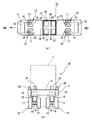
- FIG. 1 is a side view of an electric transport vehicle to which a power storage unit device according to an embodiment of the present invention has been applied.
- FIG. 2A is a plan view of an electric transport vehicle to which the power storage unit device according to the embodiment of the present invention is applied
- FIG. 2B is a front view of the electric transport vehicle.
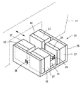
- 1 is a perspective view of a power storage unit device according to an embodiment of the present invention.
- FIG. 2 is a block diagram of a power storage unit device according to the embodiment of the present invention.
- the electric transport vehicle according to the present embodiment is an automatic guided vehicle for a plurality of containers that transports containers by receiving cargo from a vessel and a container yard in a container terminal as a port facility.
- the plurality of container guided vehicles travel on the traveling route based on instructions from an operation control device, which is a higher-level system installed at a position separated from the traveling route of the container automated guided vehicle.
- the vehicle body 11 of the automatic guided vehicle 10 for containers as an electric transport vehicle includes a carrier 12 that supports the container C.
- a pair of left and right front wheels 13 are provided on the lower front side of the vehicle body 11, and a pair of left and right rear wheels 14 are provided on the lower rear side of the vehicle body 11.
- a turning support portion 15 is provided which is capable of turning horizontally with respect to the vehicle body 11.
- a shaft case 16 that houses an axle (not shown) and a differential mechanism (not shown) is connected to a lower end of the turning support portion 15. .
- Tires 17 are respectively attached to both ends of the axle, and the front wheel 13 and the rear wheel 14 have a double tire structure including two tires 17.
- the shaft case 16 is provided with an electric motor 18 for traveling.
- a servo motor is used as the electric motor 18.
- a steering mechanism 19 is connected to an upper portion of each turning support 15. Although not shown, the steering mechanism 19 includes a steering electric motor and a speed reducer for turning the turning support unit 15. Therefore, the front wheel 13 and the rear wheel 14 can be independently steered by the operation of the steering mechanism 19.
- a plurality of stoppers 20 are provided in the vicinity of the widthwise edge of the vehicle body 11 for restricting the widthwise displacement of the container C with respect to the carrier 12.
- stoppers 21 are provided at the front and rear portions of the vehicle body 11, respectively, for restricting the longitudinal displacement of the container C mounted on the carrier 12.
- a transponder receiver 23 as an information receiving unit that can receive information of the transponder 22 embedded on the road surface of the traveling route A is provided at a front portion and a rear portion of the bottom of the vehicle body 11. I have.
- the transponder receiver 23 performs position detection by reading the transponder 22.
- the power storage unit device of the present embodiment includes a power storage unit 25 that is detachable from the container automatic guided vehicle 10. Specifically, the power storage unit 25 is provided detachably with respect to the vehicle body 11 near the middle of the vehicle body 11 in the front-rear direction.
- the power storage unit 25 stores electric power for driving the traveling electric motor 18 and the steering electric motor.
- the power storage unit 25 is substantially cubic in overall shape, and includes a power storage case 26 and four power storage modules 27 held in the power storage case 26.
- power storage unit 25 includes power supply terminal 28, charging terminal 29, changeover switch 30, control device 31, and cooling device 32.
- the power storage case 26 can accommodate and hold four power storage modules 27.
- the four power storage modules 27 are connected in parallel.
- the power supply terminal 28 is connectable to the input terminal 24 on the vehicle body 11 side, and supplies the electric power of the power storage module 27 to the electric motor 18 for traveling or the electric motor for steering on the vehicle body 11 side. Terminal for supplying to the load. That is, the power supply terminal 28 can supply power from the power storage module 27 to the container automatic guided vehicle 10.
- the power supply terminal 28 is located at the front of the power storage unit 25 when mounted on the vehicle body 11 and is provided at a position connectable to the input terminal 24 on the vehicle body 11 side.
- the charging terminal 29 is a terminal for charging the power storage module 27 by connecting to an external power supply.
- charging terminal 29 When mounted on vehicle body 11, charging terminal 29 is located at the center in the front-rear direction on the side of power storage unit 25, and is provided at a position where output terminal T of an external power supply shown in FIG. 4 is easily connected. . That is, the charging terminal 29 is provided at a position facing the outside of the vehicle body 11 when the power storage case 26 is mounted on the vehicle body 11.
- the switch 30 is a switch for switching between energization between the charging terminal 29 and the power storage module 27 and between energization between the power storage module 27 and the power supply terminal 28.
- the changeover switch 30 is connected to the control device 31, and the changeover switch 30 is controlled and switched by the control device 31. In FIG. 3, the changeover switch 30 is not shown.
- the control device 31 includes an arithmetic processing unit (not shown) for executing various programs in addition to calculating various data, and a storage unit (not shown) for storing various data and programs.
- Control device 31 is communicably connected to each power storage module 27.
- the control device 31 is connected to the charging terminal 29 and the changeover switch 30 and controls the charging terminal 29 and the changeover switch 30.
- the cooling device 32 is provided for cooling the power storage module 27, and includes an electric fan (not shown) that generates a blow in the direction of the power storage module 27.
- the cooling device 32 is connected in parallel with the power storage module 27. The cooling device 32 is activated when the power storage module 27 is charged and when the container guided vehicle 10 is traveling (discharging).
- the power storage module 27 is chargeable and dischargeable, and includes a plurality of storage batteries 33 and a battery ECU 34 that monitors the state of the storage batteries 33 and controls charging and discharging.
- Battery ECU 34 of each power storage module 27 is communicably connected to control device 31.
- the storage battery 33 of the present embodiment is a lithium ion secondary battery. Battery ECU 34 monitors and controls each unit of power storage module 27.
- the power storage module 27 is provided with a switch 35 for switching between energization and cutoff of the plurality of storage batteries 33, and also includes a current sensor 36, a leakage detection sensor 37, and a service plug 38.
- the current sensor 36 detects a current at the time of charging / discharging
- the leakage detection sensor 37 detects the presence or absence of a leakage during charging / discharging.
- the service plug 38 is a plug that is removed during maintenance work such as replacement of the storage battery 33. By removing the service plug 38, the power supply to the storage battery 33 is reliably shut off.
- the current sensor 36, the leakage detection sensor 37, and the service plug 38 are connected to the battery ECU 34.
- the battery ECU 34 receives signals from the current sensor 36, the leakage detection sensor 37, and the service plug 38 and controls on / off of the switch 35.
- the power storage unit 25 of the present embodiment can be charged while being attached to the vehicle body 11 and can be charged while being removed from the vehicle body 11.
- the output terminal T of the external power supply is connected to the charging terminal 29.
- the control device 31 detects that the output terminal T of the external power supply is connected to the charging terminal 29.
- Control device 31 controls and switches changeover switch 30 so as to cut off the current flow between power storage module 27 and power supply terminal 28 and to flow current between charge terminal 29 and power storage module 27.
- the power of the external power supply is stored in the power storage module 27 through the charging terminal 29.
- electric power is supplied to the cooling device 32 connected in parallel with the power storage module 27, and the cooling device 32 is operated.
- Each power storage module 27 is charged, and each power storage module 27 is cooled by the air blown from the cooling device 32. Since the cooling device 32 is connected in parallel with the plurality of power storage modules 27, the cooling device 32 is operated using the power of the external power supply, and does not consume the power stored in the power storage module 27.
- control device 31 controls and switches the switch 30 so as to make current flow between the power storage module 27 and the power supply terminal 28 and cut off current flow between the charging terminal 29 and the power storage module 27. . Further, control device 31 issues a command to battery ECU 34 to switch switch 35 from off to on. In response to the command, the battery ECU 34 switches the switch 35 from off to on. When the switch 35 is turned on, the electric power stored in each power storage module 27 is supplied to loads such as the electric motor 18 for traveling and the electric motor for steering through the power supply terminal 28. By supplying power to the load of the vehicle body 11, the container automatic guided vehicle 10 can travel. As described above, in the present embodiment, when charging is completed in a state where the power storage unit 25 is mounted on the vehicle body 11, the container automatic guided vehicle 10 can immediately travel.
- the switch 35 When the switch 35 is switched from off to on, the power stored in the power storage module 27 is supplied to the cooling device 32, and the cooling device 32 operates with the power of the power storage module 27. That is, the cooling device 32 operates when the container guided vehicle 10 is traveling. Therefore, at the time of discharging of power storage module 27, cooling device 32 cools power storage module 27.
- control device 31 detects that the output terminal T of the external power supply is connected to the charging terminal 29.
- Control device 31 controls and switches changeover switch 30 so as to cut off the current flow between power storage module 27 and power supply terminal 28 and to flow current between charge terminal 29 and power storage module 27.
- the power of the external power supply is stored in the power storage module 27 through the charging terminal 29.
- electric power is supplied to the cooling device 32 connected in parallel with the power storage module 27, and the cooling device 32 is operated.
- Each power storage module 27 is charged, and each power storage module 27 is cooled by the air blown from the cooling device 32. Since the cooling device 32 is connected in parallel with the plurality of power storage modules 27, it operates using the power of the external power supply, and does not consume the power stored in the power storage modules 27.
- the battery ECU 34 switches the switch 35 from on to off, and cuts off the power supply to the storage battery 33.
- the control device 31 recognizes that the charging of the power storage module 27 has been completed. After the control device 31 completes the charging of the power storage module 27, the output terminal T of the external power supply is disconnected from the charging terminal 29.
- the charged power storage unit 25 may be stored until it is replaced with another power storage unit 25 mounted on the containerless automatic guided vehicle 10.
- control device 31 controls and switches the switch 30 so as to make current flow between the power storage module 27 and the power supply terminal 28 and cut off current flow between the charging terminal 29 and the power storage module 27. . Further, control device 31 issues a command to battery ECU 34 to switch switch 35 from off to on. In response to the command, the battery ECU 34 switches the switch 35 from off to on. When the switch 35 is turned on, the electric power stored in each power storage module 27 is supplied to loads such as the electric motor 18 for traveling and the electric motor for steering through the power supply terminal 28. When electric power is supplied to the load of the vehicle body 11, the container automatic guided vehicle 10 can travel.
- the power storage unit 25 of the present embodiment has the following functions and effects.
- the power storage unit 25 includes a charging terminal 29 connectable to the output terminal T of the external power supply, a current supply between the charging terminal 29 and the power storage module 27, and a connection between the power storage module 27 and the power supply terminal 28. And a control device 31 that controls the changeover switch 30. Therefore, the power storage unit 25 removed from the containerless automatic guided vehicle 10 can be charged, and the power storage unit 25 mounted on the container automatic guided vehicle 10 can be charged. Therefore, it is possible to suppress a decrease in the transport efficiency of the containerless automatic guided vehicle 10 due to waiting for charging of the power storage unit 25 or the like.
- the power storage unit 25 includes a cooling device 32 that is connected in parallel with the power storage module 27 and cools the power storage module 27.
- the cooling device 32 is operated by the power of the external power supply through the charging terminal 29 when charging the power storage module 27 whose charging terminal 29 is connected to the output terminal T of the external power supply. In this case, even if the power storage module 27 is rapidly charged, the power storage module 27 is cooled by the cooling device 32, so that the temperature of the power storage module 27 due to the quick charging can be suppressed, and the deterioration of the power storage module 27 due to the quick charging is suppressed. be able to.
- the charging terminal 29 is provided at a position facing the outside of the container automatic guided vehicle 10 when the power storage unit 25 is mounted on the container automatic guided vehicle 10. For this reason, the charging terminal 29 is easily connected to the output terminal T of the external power supply. Therefore, it is easy to charge the power storage module 27 in a state where the power storage unit 25 is mounted on the container guided vehicle 10.
- the cooling device 32 is operated by the electric power stored in the power storage module 27 during the operation of the container automatic guided vehicle 10 in which the power storage module 27 and the power supply terminal 28 are energized. Therefore, the cooling device 32 can cool the power storage module 27 during operation of the container guided vehicle 10. Therefore, it is possible to suppress a rise in temperature of the power storage module 27 at the time of discharging, and it is possible to suppress deterioration of the power storage module 27 due to discharge.
- the power storage unit 25 can be charged while being attached to the containerless automatic guided vehicle 10, and can be charged even when it is detached from the container automatic guided vehicle 10. Therefore, the power storage unit 25 can be charged without impairing the operation efficiency of the container guided vehicle 10.
- the power storage unit 25 includes a charging terminal 29, a changeover switch 30, and a control device 31. For this reason, it is not necessary to provide a charging terminal on the automatic guided vehicle 10 for containers, and the power line can be shortened as compared with a case where a charging terminal is provided on the vehicle body 11 of the automatic guided vehicle 10 for containers. Power loss due to power transmission can be reduced.
- the containerless automatic guided vehicle 10 transports the container C, which is a large load, it repeatedly travels and stops, and the power storage unit 25 is frequently rapidly charged.
- the power storage unit 25 can cool the power storage module 27 with the power of the external power supply at the same time as charging the power storage module 27. For this reason, according to the power storage unit 25, the effect of suppressing a decrease in the transfer efficiency of the automatic guided vehicle 10 for containers and the effect of preventing the power storage module 27 from deteriorating due to a high temperature due to charging are controlled by the electric type for transferring small loads. It is large compared to the case of transport vehicles.
- the cooling device 32 Since the cooling device 32 is operated by the power of the external power supply when charging the power storage module 27, compared with the case where the cooling device is operated using the power once stored in the power storage unit during charging, the power storage The number of times of charging and discharging of the module 27 is suppressed, and the deterioration of the power storage module 27 can be suppressed by suppressing the number of times of charging and discharging.
- the power storage unit includes the cooling device.
- the cooling device is not essential, and may be a cooling device that does not include the cooling device.
- the present invention can be applied to a power storage module which does not require cooling during charging.
- the storage battery of the power storage module is a lithium ion secondary battery, but the storage battery of the power storage module is not limited to a lithium ion secondary battery.
- the storage battery of the power storage module may be, for example, a secondary battery other than a lithium ion secondary battery, such as a nickel hydride secondary battery.
- a cooling device is provided for each power storage module, but this is not a limitation. The number of cooling devices is not particularly limited.
- the air-cooling type cooling device using the blower fan is used, but a water-cooling type cooling device using a radiator and a radiator fan may be used.
- the cooling device cools the power storage module during quick charging and traveling, but the cooling device may cool only during quick charging. Further, even when cooling during traveling, the amount of air blown by the cooling device may be increased or decreased according to the discharge.
- the container automatic guided vehicle is described as an example of the electric transport vehicle to which the power storage unit device is applied.
- the electric transport vehicle is not limited to the container automatic transport system.
- a manned electric transfer vehicle may be used, and a load to be transferred may be a load other than a container.
Abstract
This power storage unit (25) is provided with: a charging terminal (29) that is connectable to an external power supply; a changeover switch (30) that switches between conduction of the charging terminal (29) and a power storage module (27) and conduction of the power storage module (27) and a power feeding terminal (28); and a control device (31) for controlling the changeover switch (30); wherein the control device (31) controls the changeover switch (30) so that, when the charging terminal (29) is connected to the external power source, the charging terminal (29) and the power storage module (27) are brought into conduction, and the conduction between the power storage module (27) and the power feeding terminal (28) is interrupted.
Description
この発明は、電動式搬送車両の蓄電ユニット装置に関する。
The present invention relates to a power storage unit device for an electric transport vehicle.
従来の電動式搬送車両の蓄電ユニット装置としては、例えば、特許文献1に開示された電動無人搬送車両が知られている。特許文献1の電動無人搬送車は、バッテリに貯蔵されている電力を動力源として自律走行する電動車両である。この電動無人搬送車は、荷台の下部に設けられた充電装置格納箱と、充電装置格納箱から所定間隔離されて荷台から懸架されたバッテリを有している。
電動 As a conventional power storage unit device of an electric transport vehicle, for example, an electric unmanned transport vehicle disclosed in Patent Document 1 is known. The electric automatic guided vehicle disclosed in Patent Document 1 is an electric vehicle that autonomously runs using electric power stored in a battery as a power source. This electric automatic guided vehicle has a charging device storage box provided at a lower portion of the loading platform, and a battery suspended from the loading platform and separated from the charging device storage box by a predetermined distance.
充電装置格納箱には、電力供給制御装置と、接続器と、充電装置とが設けられている。バッテリの電力は、主に、電力供給制御装置を介して、走行装置へ供給される。外部より供給される商用電源の電力は、個別に接続器へ入力され、その入力された電力の一つが充電装置へ供給される。その結果、充電装置によりバッテリが充電される。
The charging device storage box is provided with a power supply control device, a connector, and a charging device. The power of the battery is mainly supplied to the traveling device via the power supply control device. The power of the commercial power supplied from the outside is individually input to the connector, and one of the input power is supplied to the charging device. As a result, the battery is charged by the charging device.
しかしながら、特許文献1に開示された電動無人搬送車では、接続器がバッテリと離れた場所に設けられているため、バッテリを電動無人搬送車から取り外し、外部の商用電源の電力を取り外したバッテリに充電することができないという問題がある。この場合、バッテリを充電するために電動無人搬送車が待機することになり、電動無人搬送車の搬送効率が低下する。また、バッテリを電動無人搬送車から取り外さずに急速充電する場合では、バッテリの種類によってはバッテリの冷却が必要である。バッテリに冷却装置を設けて充電中のバッテリを冷却することも考えられるが、充電時には冷却装置がバッテリに充電された電力を消費するため、バッテリの劣化が促進されるという問題を生じる。特に、コンテナ等の大型の荷を搬送する電動式搬送車両では、荷の搬送と停止を繰り返し、充電の頻度が高くなることから、バッテリの劣化を抑制することが要請されている。
However, in the electric automatic guided vehicle disclosed in Patent Literature 1, since the connector is provided at a location away from the battery, the battery is removed from the electric automatic guided vehicle and the battery is disconnected from the external commercial power supply. There is a problem that it cannot be charged. In this case, the electric automatic guided vehicle stands by to charge the battery, and the transfer efficiency of the electric automatic guided vehicle is reduced. In the case where the battery is rapidly charged without being removed from the electric automatic guided vehicle, the battery needs to be cooled depending on the type of the battery. It is conceivable to provide a cooling device in the battery to cool the battery during charging. However, at the time of charging, the cooling device consumes the electric power charged in the battery, which causes a problem that deterioration of the battery is accelerated. In particular, in an electric transport vehicle that transports a large load such as a container, the load is repeatedly transferred and stopped, and the frequency of charging is increased. Therefore, it is required to suppress the deterioration of the battery.
本発明は上記の問題点に鑑みてなされたもので、本発明の目的は、電動式無人搬送車両に装着した状態で充電できるほか、電動式無人搬送車から取り外した状態で充電できる電動式搬送車両の蓄電ユニット装置の提供にある。
SUMMARY OF THE INVENTION The present invention has been made in view of the above problems, and an object of the present invention is to provide an electric carrier that can be charged while being attached to an electric automatic guided vehicle and that can be charged while being detached from the electric automated guided vehicle. Another object is to provide a power storage unit device for a vehicle.
上記の課題を解決するために、本発明は、充放電可能な蓄電モジュールを収容可能とし、電動式搬送車両に対して着脱可能な蓄電ユニットを備え、前記蓄電ユニットは、前記電動式搬送車両の入力端子と接続可能であって、前記蓄電モジュールから前記電動式搬送車両へ給電可能とする給電用端子を備えた電動式搬送車両の蓄電ユニット装置において、前記蓄電ユニットは、外部電源と接続可能な充電用端子と、前記充電用端子と前記蓄電モジュールとの間の通電と、前記蓄電モジュールと前記給電用端子との間の通電を切り換える切換スイッチと、前記切換スイッチを制御する制御装置と、を備え、前記制御装置は、前記充電用端子が前記外部電源と接続されるとき、前記充電用端子と前記蓄電モジュールとの間を通電させるとともに、前記蓄電モジュールと前記給電用端子との間の通電を遮断するように前記切換スイッチを制御することを特徴とする。
In order to solve the above problems, the present invention is capable of accommodating a chargeable / dischargeable power storage module and includes a power storage unit detachable from an electric transport vehicle, wherein the power storage unit includes In a power storage unit device of an electric transport vehicle that is connectable to an input terminal and includes a power supply terminal that can supply power to the electric transport vehicle from the power storage module, the power storage unit is connectable to an external power supply. A charging terminal, a switch that switches between energization between the charging terminal and the power storage module, a switch that switches energization between the power storage module and the power supply terminal, and a control device that controls the switch. The control device, when the charging terminal is connected to the external power supply, while energizing between the charging terminal and the power storage module, Controlling said selector switch so as to cut off the energization between the serial and the power storage module and the power supply terminal and said.
本発明では、蓄電ユニットは、外部電源と接続可能な充電用端子と、充電用端子と蓄電モジュールとの間の通電と、蓄電モジュールと給電用端子との間の通電を切り換える通電切換器と、通電切換器を制御する制御装置と、を備える。このため、電動式搬送車両から取り外された蓄電ユニットを充電することができるほか、電動式搬送車両に装着された蓄電ユニットを充電することができる。したがって、蓄電ユニットの充電待ち等による電動式搬送車両の搬送効率の低下を抑制することができる。また、蓄電ユニットが故障して電動式搬送車両が停止しても、充電済みの蓄電モジュールを備えた蓄電ユニットと交換すれば、停止した電動式搬送車両を牽引する作業が大幅に削減され、電動式搬送車両の保守作業の効率が向上する。
In the present invention, the power storage unit includes a charging terminal connectable to an external power supply, energization between the charging terminal and the power storage module, and an energization switch that switches energization between the power storage module and the power supply terminal. A control device for controlling the energization switch. Therefore, the power storage unit detached from the electric transport vehicle can be charged, and the power storage unit mounted on the electric transport vehicle can be charged. Therefore, it is possible to suppress a decrease in the transport efficiency of the electric transport vehicle due to waiting for charging of the power storage unit. In addition, even if the power storage unit fails and the electric transport vehicle stops, replacing the power storage unit with a charged power storage module greatly reduces the work of towing the stopped electric transport vehicle. The efficiency of maintenance work of the transport vehicle is improved.
また、上記の電動式搬送車両の蓄電ユニット装置において、前記蓄電モジュールと並列接続され、前記蓄電モジュールを冷却する冷却装置を備え、前記冷却装置は、前記充電用端子が前記外部電源と接続される前記蓄電モジュールの充電時に、前記充電用端子を通じた前記外部電源の電力により作動される構成としてもよい。
この場合、蓄電モジュールを急速充電しても、冷却装置によって蓄電モジュールが冷却されるので、急速充電による蓄電ユニットの高温化を抑制でき、急速充電による蓄電モジュールの劣化を抑制することができる。 In the power storage unit device for the electric transport vehicle, the power storage unit further includes a cooling device that is connected in parallel with the power storage module and cools the power storage module, and the charging device has the charging terminal connected to the external power supply. When the power storage module is charged, the power storage module may be configured to be operated by the power of the external power supply through the charging terminal.
In this case, even if the power storage module is rapidly charged, the cooling device cools the power storage module, so that the temperature of the power storage unit due to the quick charging can be suppressed, and deterioration of the power storage module due to the quick charging can be suppressed.
また、上記の電動式搬送車両の蓄電ユニット装置において、前記充電用端子は、前記蓄電ユニットが前記電動式搬送車両に装着された状態では、前記電動式搬送車両の外側を臨む位置に設けられている構成としてもよい。
この場合、蓄電ユニットが電動式搬送車両に装着された状態では、充電用端子が電動式搬送車両の外側を臨むため、充電用端子は外部電源と接続し易くなる。よって、蓄電ユニットが電動式搬送車両に装着された状態での蓄電モジュールの充電が行い易い。 In the power storage unit device for an electric transport vehicle described above, the charging terminal is provided at a position facing the outside of the electric transport vehicle when the power storage unit is mounted on the electric transport vehicle. Configuration.
In this case, when the power storage unit is mounted on the electric transport vehicle, the charging terminal faces the outside of the electric transport vehicle, so that the charging terminal is easily connected to an external power supply. Therefore, it is easy to charge the power storage module in a state where the power storage unit is mounted on the electric transport vehicle.
また、上記の電動式搬送車両の蓄電ユニット装置において、前記冷却装置は、前記蓄電モジュールと前記給電用端子とが通電される電動式搬送車の運転時に前記蓄電モジュールに蓄電された電力により作動される構成としてもよい。
この場合、冷却装置は電動式搬送車両の運転時に蓄電モジュールを冷却することができる。よって、蓄電モジュールの放電時における高温化を抑制でき、放電による蓄電モジュールの劣化を抑制することができる。 In the above power storage unit device for an electric transport vehicle, the cooling device is operated by the electric power stored in the power storage module during operation of the electric transport vehicle in which the power storage module and the power supply terminal are energized. May be adopted.
In this case, the cooling device can cool the power storage module during operation of the electric transport vehicle. Therefore, it is possible to suppress an increase in the temperature of the power storage module during discharging, and to suppress deterioration of the power storage module due to the discharge.
本発明によれば、電動式無人搬送車両に装着した状態で充電できるほか、電動式無人搬送車から取り外した状態で充電できる電動式搬送車両の蓄電ユニット装置を提供することができる。
According to the present invention, it is possible to provide a power storage unit device of an electric transport vehicle that can be charged while being attached to an electric automatic guided vehicle and that can be charged while being detached from the electric automated guided vehicle.
以下、本発明の実施形態に係る電動式搬送車両の蓄電ユニット装置について図面を参照して説明する。本実施形態の電動式搬送車両は、港湾設備としてのコンテナターミナルにおいて船舶とコンテナヤードとの間にてコンテナの荷役を受けてコンテナを搬送する複数のコンテナ用無人搬送車である。複数のコンテナ用無人搬送車は、コンテナ用無人搬送車の走行経路から離隔する位置に設置された上位システムである運用制御装置からの指令に基づいて走行経路を走行する。
Hereinafter, a power storage unit device for an electric transport vehicle according to an embodiment of the present invention will be described with reference to the drawings. The electric transport vehicle according to the present embodiment is an automatic guided vehicle for a plurality of containers that transports containers by receiving cargo from a vessel and a container yard in a container terminal as a port facility. The plurality of container guided vehicles travel on the traveling route based on instructions from an operation control device, which is a higher-level system installed at a position separated from the traveling route of the container automated guided vehicle.
図1に示すように、電動式搬送車両としてのコンテナ用無人搬送車10の車体11は、コンテナCを支持する荷台12を備えている。車体11の下部前側には左右一対の前輪13を備え、車体11の下部後側には左右一対の後輪14が備えられている。前輪13および後輪14について説明すると、車体11に対して水平方向に旋回自在の旋回支持部15が設けられている。図2(a)、図2(b)に示すように、旋回支持部15の下端には、車軸(図示せず)およびデフ機構(図示せず)を収容する軸ケース16が連結されている。車軸の両端にはタイヤ17がそれぞれ取り付けられており、前輪13および後輪14は、2本のタイヤ17を備えるダブルタイヤ構造となっている。軸ケース16には走行用の電動モータ18が設けられている。本実施形態では電動モータ18としてサーボモータが用いられている。
As shown in FIG. 1, the vehicle body 11 of the automatic guided vehicle 10 for containers as an electric transport vehicle includes a carrier 12 that supports the container C. A pair of left and right front wheels 13 are provided on the lower front side of the vehicle body 11, and a pair of left and right rear wheels 14 are provided on the lower rear side of the vehicle body 11. Describing the front wheel 13 and the rear wheel 14, a turning support portion 15 is provided which is capable of turning horizontally with respect to the vehicle body 11. As shown in FIGS. 2A and 2B, a shaft case 16 that houses an axle (not shown) and a differential mechanism (not shown) is connected to a lower end of the turning support portion 15. . Tires 17 are respectively attached to both ends of the axle, and the front wheel 13 and the rear wheel 14 have a double tire structure including two tires 17. The shaft case 16 is provided with an electric motor 18 for traveling. In this embodiment, a servo motor is used as the electric motor 18.
各旋回支持部15の上部には、操舵機構19がそれぞれ連結されている。操舵機構19は、図示されないが旋回支持部15を旋回させるための操舵用の電動モータおよび減速機を備えている。従って、前輪13および後輪14は操舵機構19の作動により互いに独立して操舵可能である。
操 A steering mechanism 19 is connected to an upper portion of each turning support 15. Although not shown, the steering mechanism 19 includes a steering electric motor and a speed reducer for turning the turning support unit 15. Therefore, the front wheel 13 and the rear wheel 14 can be independently steered by the operation of the steering mechanism 19.
車体11の幅方向の縁部付近には、荷台12に対するコンテナCの幅方向の位置ずれを規制する複数のストッパ20が備えられている。また、車体11の前部および後部には、荷台12に搭載されるコンテナCの長さ方向の位置ずれを規制するストッパ21がそれぞれ設けられている。
A plurality of stoppers 20 are provided in the vicinity of the widthwise edge of the vehicle body 11 for restricting the widthwise displacement of the container C with respect to the carrier 12. In addition, stoppers 21 are provided at the front and rear portions of the vehicle body 11, respectively, for restricting the longitudinal displacement of the container C mounted on the carrier 12.
図1に示すように、車体11の底部における前部および後部には、走行経路Aにおける路面に埋設されたトランスポンダ22の情報を受信可能とする情報受信部としてのトランスポンダ受信機23が備えられている。トランスポンダ受信機23はトランスポンダ22を読み取ることにより位置検出を行う。
As shown in FIG. 1, a transponder receiver 23 as an information receiving unit that can receive information of the transponder 22 embedded on the road surface of the traveling route A is provided at a front portion and a rear portion of the bottom of the vehicle body 11. I have. The transponder receiver 23 performs position detection by reading the transponder 22.
本実施形態の蓄電ユニット装置は、コンテナ用無人搬送車10に対して着脱可能な蓄電ユニット25を備えている。具体的には、蓄電ユニット25は、車体11の前後方向における中間付近において車体11に対して着脱可能に備えられている。蓄電ユニット25は、走行用の電動モータ18や操舵用の電動モータを駆動するための電力が蓄えられる。図3に示すように、蓄電ユニット25は、全体形状としては略立方体であり、蓄電ケース26と、蓄電ケース26に保持される4つの蓄電モジュール27を備えている。さらに、図4に示すように、蓄電ユニット25は、給電用端子28と、充電用端子29と、切換スイッチ30と、制御装置31と、冷却装置32と、を備えている。
The power storage unit device of the present embodiment includes a power storage unit 25 that is detachable from the container automatic guided vehicle 10. Specifically, the power storage unit 25 is provided detachably with respect to the vehicle body 11 near the middle of the vehicle body 11 in the front-rear direction. The power storage unit 25 stores electric power for driving the traveling electric motor 18 and the steering electric motor. As shown in FIG. 3, the power storage unit 25 is substantially cubic in overall shape, and includes a power storage case 26 and four power storage modules 27 held in the power storage case 26. Furthermore, as shown in FIG. 4, power storage unit 25 includes power supply terminal 28, charging terminal 29, changeover switch 30, control device 31, and cooling device 32.
蓄電ケース26は4つの蓄電モジュール27を収容可能であって保持する。4つの蓄電モジュール27は並列接続されている。図4に示すように、給電用端子28は、車体11側の入力端子24と接続可能であり、蓄電モジュール27の電力を車体11側の走行用の電動モータ18や操舵用の電動モータ等の負荷へ供給するための端子である。つまり、給電用端子28は、蓄電モジュール27からコンテナ用無人搬送車10へ給電可能とする。給電用端子28は、車体11に装着された状態では、蓄電ユニット25の前部に位置し、車体11側の入力端子24と接続可能な位置に設けられている。
電 The power storage case 26 can accommodate and hold four power storage modules 27. The four power storage modules 27 are connected in parallel. As shown in FIG. 4, the power supply terminal 28 is connectable to the input terminal 24 on the vehicle body 11 side, and supplies the electric power of the power storage module 27 to the electric motor 18 for traveling or the electric motor for steering on the vehicle body 11 side. Terminal for supplying to the load. That is, the power supply terminal 28 can supply power from the power storage module 27 to the container automatic guided vehicle 10. The power supply terminal 28 is located at the front of the power storage unit 25 when mounted on the vehicle body 11 and is provided at a position connectable to the input terminal 24 on the vehicle body 11 side.
充電用端子29は、外部電源との接続により蓄電モジュール27を充電するための端子である。充電用端子29は、車体11に装着された状態では、蓄電ユニット25の側部における前後方向の中心に位置し、図4に示す外部電源の出力端子Tが接続され易い位置に設けられている。つまり、充電用端子29は、蓄電ケース26が車体11に装着された状態では、車体11の外側を臨む位置に設けられている。
The charging terminal 29 is a terminal for charging the power storage module 27 by connecting to an external power supply. When mounted on vehicle body 11, charging terminal 29 is located at the center in the front-rear direction on the side of power storage unit 25, and is provided at a position where output terminal T of an external power supply shown in FIG. 4 is easily connected. . That is, the charging terminal 29 is provided at a position facing the outside of the vehicle body 11 when the power storage case 26 is mounted on the vehicle body 11.
切換スイッチ30は充電用端子29と蓄電モジュール27との間の通電と、蓄電モジュール27と給電用端子28との間の通電を切り換えるスイッチである。切換スイッチ30は制御装置31と接続されており、切換スイッチ30は、制御装置31により制御され、切り換えられる。図3では、切換スイッチ30は図示されない。
The switch 30 is a switch for switching between energization between the charging terminal 29 and the power storage module 27 and between energization between the power storage module 27 and the power supply terminal 28. The changeover switch 30 is connected to the control device 31, and the changeover switch 30 is controlled and switched by the control device 31. In FIG. 3, the changeover switch 30 is not shown.
制御装置31は、各種データを計算するほか、プログラムを実行する演算処理部(図示せず)と、各種データおよびプログラムを記憶する記憶部(図示せず)と、を備えている。制御装置31は、各蓄電モジュール27と通信可能に接続されている。制御装置31は、充電用端子29および切換スイッチ30と接続されており、充電用端子29および切換スイッチ30を制御する。
The control device 31 includes an arithmetic processing unit (not shown) for executing various programs in addition to calculating various data, and a storage unit (not shown) for storing various data and programs. Control device 31 is communicably connected to each power storage module 27. The control device 31 is connected to the charging terminal 29 and the changeover switch 30 and controls the charging terminal 29 and the changeover switch 30.
冷却装置32は、蓄電モジュール27を冷却するために設けられており、蓄電モジュール27の方向への送風を発生する電動ファン(図示せず)を備えている。冷却装置32は、蓄電モジュール27と並例接続されている。冷却装置32は、蓄電モジュール27の充電時およびコンテナ用無人搬送車10の走行時(放電時)に作動される。
(4) The cooling device 32 is provided for cooling the power storage module 27, and includes an electric fan (not shown) that generates a blow in the direction of the power storage module 27. The cooling device 32 is connected in parallel with the power storage module 27. The cooling device 32 is activated when the power storage module 27 is charged and when the container guided vehicle 10 is traveling (discharging).
次に、蓄電モジュール27について説明すると、蓄電モジュール27は充放電可能であり、複数の蓄電池33と、蓄電池33の状態を監視して充放電を制御する電池ECU34を備えている。各蓄電モジュール27の電池ECU34は、制御装置31と通信可能に接続されている。本実施形態の蓄電池33はリチウムイオン二次電池である。電池ECU34は、蓄電モジュール27の各部を監視して制御する。
Next, the power storage module 27 will be described. The power storage module 27 is chargeable and dischargeable, and includes a plurality of storage batteries 33 and a battery ECU 34 that monitors the state of the storage batteries 33 and controls charging and discharging. Battery ECU 34 of each power storage module 27 is communicably connected to control device 31. The storage battery 33 of the present embodiment is a lithium ion secondary battery. Battery ECU 34 monitors and controls each unit of power storage module 27.
図4に示すように、複数の蓄電池33は直列接続されている。蓄電モジュール27には、複数の蓄電池33の通電と遮断とを切り換えるスイッチ35が設けられているほか、電流センサ36、漏電検出センサ37およびサービスプラグ38が備えられている。電流センサ36は充放電時の電流を検出し、漏電検出センサ37は充放電時における漏電の有無を検出する。サービスプラグ38は、蓄電池33の交換等の保守作業の際に取り外すプラグであり、サービスプラグ38を取り外すことにより蓄電池33における通電が確実に遮断される。電流センサ36、漏電検出センサ37およびサービスプラグ38は電池ECU34と接続されている。電池ECU34は、電流センサ36、漏電検出センサ37およびサービスプラグ38の信号の伝達を受けて、スイッチ35のオン・オフを制御する。
よ う As shown in FIG. 4, the plurality of storage batteries 33 are connected in series. The power storage module 27 is provided with a switch 35 for switching between energization and cutoff of the plurality of storage batteries 33, and also includes a current sensor 36, a leakage detection sensor 37, and a service plug 38. The current sensor 36 detects a current at the time of charging / discharging, and the leakage detection sensor 37 detects the presence or absence of a leakage during charging / discharging. The service plug 38 is a plug that is removed during maintenance work such as replacement of the storage battery 33. By removing the service plug 38, the power supply to the storage battery 33 is reliably shut off. The current sensor 36, the leakage detection sensor 37, and the service plug 38 are connected to the battery ECU 34. The battery ECU 34 receives signals from the current sensor 36, the leakage detection sensor 37, and the service plug 38 and controls on / off of the switch 35.
次に、本実施形態の蓄電ユニット25の充電について説明する。本実施形態の蓄電ユニット25は、車体11に装着された状態での充電が可能であるほか、車体11から取り外された状態での充電が可能である。
Next, charging of the power storage unit 25 of the present embodiment will be described. The power storage unit 25 of the present embodiment can be charged while being attached to the vehicle body 11 and can be charged while being removed from the vehicle body 11.
車体11に装着された状態の蓄電ユニット25を充電する場合、外部電源の出力端子Tを充電用端子29に接続する。制御装置31は充電用端子29に外部電源の出力端子Tが接続されたことを検知する。制御装置31は、蓄電モジュール27と給電用端子28との間の通電を遮断し、充電用端子29と蓄電モジュール27との間を通電させるように、切換スイッチ30を制御して切り換える。
(4) When charging the power storage unit 25 mounted on the vehicle body 11, the output terminal T of the external power supply is connected to the charging terminal 29. The control device 31 detects that the output terminal T of the external power supply is connected to the charging terminal 29. Control device 31 controls and switches changeover switch 30 so as to cut off the current flow between power storage module 27 and power supply terminal 28 and to flow current between charge terminal 29 and power storage module 27.
切換スイッチ30の切り換えにより、外部電源の電力は充電用端子29を通じて蓄電モジュール27へ蓄えられる。このとき、蓄電モジュール27と並列接続されている冷却装置32へ電力が供給され、冷却装置32が作動される。各蓄電モジュール27に蓄電されるとともに、冷却装置32から発生する送風によって各蓄電モジュール27が冷却される。冷却装置32は、複数の蓄電モジュール27と並列接続であるため、外部電源の電力を使って作動され、蓄電モジュール27に蓄えられた電力を消費することはない。
(4) By switching the changeover switch 30, the power of the external power supply is stored in the power storage module 27 through the charging terminal 29. At this time, electric power is supplied to the cooling device 32 connected in parallel with the power storage module 27, and the cooling device 32 is operated. Each power storage module 27 is charged, and each power storage module 27 is cooled by the air blown from the cooling device 32. Since the cooling device 32 is connected in parallel with the plurality of power storage modules 27, the cooling device 32 is operated using the power of the external power supply, and does not consume the power stored in the power storage module 27.
蓄電モジュール27の各蓄電池33が満充電となると、電池ECU34はスイッチ35をオンからオフに切り換えて、蓄電池33への通電を遮断する。各蓄電モジュール27の蓄電池33が満充電になると、制御装置31は、蓄電モジュール27の充電が完了したことを認識する。制御装置31が蓄電モジュール27の充電を完了した後、外部電源の出力端子Tを充電用端子29から切り離す。
(4) When each storage battery 33 of the power storage module 27 is fully charged, the battery ECU 34 switches the switch 35 from on to off, and cuts off the power supply to the storage battery 33. When the storage battery 33 of each power storage module 27 is fully charged, the control device 31 recognizes that the charging of the power storage module 27 has been completed. After the control device 31 completes the charging of the power storage module 27, the output terminal T of the external power supply is disconnected from the charging terminal 29.
次に、制御装置31は、蓄電モジュール27と給電用端子28との間を通電させ、充電用端子29と蓄電モジュール27との間の通電を遮断するように、切換スイッチ30を制御して切り換える。さらに、制御装置31は、電池ECU34に対してスイッチ35をオフからオンに切り換える指令を出す。電池ECU34は指令を受けてスイッチ35をオフからオンに切り換える。スイッチ35がオンに切り換わることにより、各蓄電モジュール27に蓄えられている電力が給電用端子28を通じて走行用の電動モータ18や操舵用の電動モータ等の負荷へ供給される。車体11の負荷へ電力が供給されることにより、コンテナ用無人搬送車10は走行可能となる。このように、本実施形態では、蓄電ユニット25が車体11に装着された状態で充電が完了すると、コンテナ用無人搬送車10は直ちに走行可能となる。
Next, the control device 31 controls and switches the switch 30 so as to make current flow between the power storage module 27 and the power supply terminal 28 and cut off current flow between the charging terminal 29 and the power storage module 27. . Further, control device 31 issues a command to battery ECU 34 to switch switch 35 from off to on. In response to the command, the battery ECU 34 switches the switch 35 from off to on. When the switch 35 is turned on, the electric power stored in each power storage module 27 is supplied to loads such as the electric motor 18 for traveling and the electric motor for steering through the power supply terminal 28. By supplying power to the load of the vehicle body 11, the container automatic guided vehicle 10 can travel. As described above, in the present embodiment, when charging is completed in a state where the power storage unit 25 is mounted on the vehicle body 11, the container automatic guided vehicle 10 can immediately travel.
スイッチ35がオフからオンに切り換わることにより、蓄電モジュール27に蓄えられている電力が冷却装置32へ供給され、冷却装置32は蓄電モジュール27の電力により作動する。つまり、冷却装置32はコンテナ用無人搬送車10の走行時に作動する。したがって、蓄電モジュール27の放電時において、冷却装置32は蓄電モジュール27を冷却する。
When the switch 35 is switched from off to on, the power stored in the power storage module 27 is supplied to the cooling device 32, and the cooling device 32 operates with the power of the power storage module 27. That is, the cooling device 32 operates when the container guided vehicle 10 is traveling. Therefore, at the time of discharging of power storage module 27, cooling device 32 cools power storage module 27.
車体11から取り外された状態の蓄電ユニット25を充電する場合について説明する。この場合も外部電源の出力端子Tを充電用端子29に接続する。制御装置31は充電用端子29に外部電源の出力端子Tが接続されたことを検知する。制御装置31は、蓄電モジュール27と給電用端子28との間の通電を遮断し、充電用端子29と蓄電モジュール27との間を通電させるように、切換スイッチ30を制御して切り換える。
A case where the power storage unit 25 removed from the vehicle body 11 is charged will be described. Also in this case, the output terminal T of the external power supply is connected to the charging terminal 29. The control device 31 detects that the output terminal T of the external power supply is connected to the charging terminal 29. Control device 31 controls and switches changeover switch 30 so as to cut off the current flow between power storage module 27 and power supply terminal 28 and to flow current between charge terminal 29 and power storage module 27.
切換スイッチ30の切り換えにより、外部電源の電力は充電用端子29を通じて蓄電モジュール27へ蓄えられる。このとき、蓄電モジュール27と並列接続されている冷却装置32へ電力が供給され、冷却装置32が作動される。各蓄電モジュール27に蓄電されるとともに、冷却装置32から発生する送風によって各蓄電モジュール27が冷却される。冷却装置32は、複数の蓄電モジュール27と並列接続であるため、外部電源の電力を使って作動し、蓄電モジュール27に蓄えられた電力を消費することはない。
(4) By switching the changeover switch 30, the power of the external power supply is stored in the power storage module 27 through the charging terminal 29. At this time, electric power is supplied to the cooling device 32 connected in parallel with the power storage module 27, and the cooling device 32 is operated. Each power storage module 27 is charged, and each power storage module 27 is cooled by the air blown from the cooling device 32. Since the cooling device 32 is connected in parallel with the plurality of power storage modules 27, it operates using the power of the external power supply, and does not consume the power stored in the power storage modules 27.
蓄電モジュール27の各蓄電池33が満充電となると、電池ECU34はスイッチ35をオンからオフに切り換えて、蓄電池33への通電を遮断する。各蓄電モジュール27の蓄電池33が満充電になると、制御装置31は、蓄電モジュール27の充電が完了したことを認識する。制御装置31が蓄電モジュール27の充電を完了した後、外部電源の出力端子Tを充電用端子29から切り離す。充電が完了した蓄電ユニット25は、コンテナ用無人搬送車10に装着されている別の蓄電ユニット25と交換するまで保管しておけばよい。
(4) When each storage battery 33 of the power storage module 27 is fully charged, the battery ECU 34 switches the switch 35 from on to off, and cuts off the power supply to the storage battery 33. When the storage battery 33 of each power storage module 27 is fully charged, the control device 31 recognizes that the charging of the power storage module 27 has been completed. After the control device 31 completes the charging of the power storage module 27, the output terminal T of the external power supply is disconnected from the charging terminal 29. The charged power storage unit 25 may be stored until it is replaced with another power storage unit 25 mounted on the containerless automatic guided vehicle 10.
充電が完了した蓄電ユニット25が交換によりコンテナ用無人搬送車10に装着されると、入力端子24が給電用端子28と接続される。次に、制御装置31は、蓄電モジュール27と給電用端子28との間を通電させ、充電用端子29と蓄電モジュール27との間の通電を遮断するように、切換スイッチ30を制御して切り換える。さらに、制御装置31は、電池ECU34に対してスイッチ35をオフからオンに切り換える指令を出す。電池ECU34は指令を受けてスイッチ35をオフからオンに切り換える。スイッチ35がオンに切り換わることにより、各蓄電モジュール27に蓄えられている電力が給電用端子28を通じて走行用の電動モータ18や操舵用の電動モータ等の負荷へ供給される。車体11の負荷へ電力が供給されることにより、コンテナ用無人搬送車10は走行可能となる。
When the charged power storage unit 25 is mounted on the container guided vehicle 10 by replacement, the input terminal 24 is connected to the power supply terminal 28. Next, the control device 31 controls and switches the switch 30 so as to make current flow between the power storage module 27 and the power supply terminal 28 and cut off current flow between the charging terminal 29 and the power storage module 27. . Further, control device 31 issues a command to battery ECU 34 to switch switch 35 from off to on. In response to the command, the battery ECU 34 switches the switch 35 from off to on. When the switch 35 is turned on, the electric power stored in each power storage module 27 is supplied to loads such as the electric motor 18 for traveling and the electric motor for steering through the power supply terminal 28. When electric power is supplied to the load of the vehicle body 11, the container automatic guided vehicle 10 can travel.
また、スイッチ35がオフからオンに切り換わることにより、蓄電モジュール27に蓄えられている電力が冷却装置32へ供給され、冷却装置32はコンテナ用無人搬送車10の走行時に作動する。つまり、蓄電モジュール27の放電時において、冷却装置32は蓄電モジュール27を冷却する。
(4) When the switch 35 is switched from off to on, the power stored in the power storage module 27 is supplied to the cooling device 32, and the cooling device 32 operates when the container guided vehicle 10 travels. That is, when the power storage module 27 is discharged, the cooling device 32 cools the power storage module 27.
本実施形態の蓄電ユニット25は以下の作用効果を奏する。
(1)蓄電ユニット25は、外部電源の出力端子Tと接続可能な充電用端子29と、充電用端子29と蓄電モジュール27との間の通電と、蓄電モジュール27と給電用端子28との間の通電を切り換える切換スイッチ30と、切換スイッチ30を制御する制御装置31と、を備える。このため、コンテナ用無人搬送車10から取り外された蓄電ユニット25を充電することができるほか、コンテナ用無人搬送車10に装着された蓄電ユニット25を充電することができる。したがって、蓄電ユニット25の充電待ち等によるコンテナ用無人搬送車10の搬送効率の低下を抑制することができる。また、蓄電モジュール27が故障してコンテナ用無人搬送車10が停止しても、故障した蓄電ユニット25と充電済みの蓄電モジュール27を備えた蓄電ユニット25とを入れ換えて交換すれば、停止したコンテナ用無人搬送車10を牽引する作業が大幅に削減され、コンテナ用無人搬送車10の保守作業の効率が向上する。 Thepower storage unit 25 of the present embodiment has the following functions and effects.
(1) Thepower storage unit 25 includes a charging terminal 29 connectable to the output terminal T of the external power supply, a current supply between the charging terminal 29 and the power storage module 27, and a connection between the power storage module 27 and the power supply terminal 28. And a control device 31 that controls the changeover switch 30. Therefore, the power storage unit 25 removed from the containerless automatic guided vehicle 10 can be charged, and the power storage unit 25 mounted on the container automatic guided vehicle 10 can be charged. Therefore, it is possible to suppress a decrease in the transport efficiency of the containerless automatic guided vehicle 10 due to waiting for charging of the power storage unit 25 or the like. Further, even if the power storage module 27 fails and the container automatic guided vehicle 10 stops, if the failed power storage unit 25 is replaced with the charged power storage unit 25 having the charged power storage module 27 and replaced, the stopped container is stopped. The operation of towing the automatic guided vehicle 10 for containers is greatly reduced, and the efficiency of the maintenance operation of the automatic guided vehicle 10 for containers is improved.
(1)蓄電ユニット25は、外部電源の出力端子Tと接続可能な充電用端子29と、充電用端子29と蓄電モジュール27との間の通電と、蓄電モジュール27と給電用端子28との間の通電を切り換える切換スイッチ30と、切換スイッチ30を制御する制御装置31と、を備える。このため、コンテナ用無人搬送車10から取り外された蓄電ユニット25を充電することができるほか、コンテナ用無人搬送車10に装着された蓄電ユニット25を充電することができる。したがって、蓄電ユニット25の充電待ち等によるコンテナ用無人搬送車10の搬送効率の低下を抑制することができる。また、蓄電モジュール27が故障してコンテナ用無人搬送車10が停止しても、故障した蓄電ユニット25と充電済みの蓄電モジュール27を備えた蓄電ユニット25とを入れ換えて交換すれば、停止したコンテナ用無人搬送車10を牽引する作業が大幅に削減され、コンテナ用無人搬送車10の保守作業の効率が向上する。 The
(1) The
(2)蓄電ユニット25は、蓄電モジュール27と並列接続され、蓄電モジュール27を冷却する冷却装置32を備えている。冷却装置32は、充電用端子29が外部電源の出力端子Tと接続される蓄電モジュール27の充電時に、充電用端子29を通じた外部電源の電力により作動される。この場合、蓄電モジュール27を急速充電しても、冷却装置32によって蓄電モジュール27が冷却されるので、急速充電による蓄電モジュール27の高温化を抑制でき、急速充電による蓄電モジュール27の劣化を抑制することができる。
(2) The power storage unit 25 includes a cooling device 32 that is connected in parallel with the power storage module 27 and cools the power storage module 27. The cooling device 32 is operated by the power of the external power supply through the charging terminal 29 when charging the power storage module 27 whose charging terminal 29 is connected to the output terminal T of the external power supply. In this case, even if the power storage module 27 is rapidly charged, the power storage module 27 is cooled by the cooling device 32, so that the temperature of the power storage module 27 due to the quick charging can be suppressed, and the deterioration of the power storage module 27 due to the quick charging is suppressed. be able to.
(3)充電用端子29は、蓄電ユニット25がコンテナ用無人搬送車10に装着された状態では、コンテナ用無人搬送車10の外側を臨む位置に設けられている。このため、充電用端子29は外部電源の出力端子Tと接続し易くなる。よって、蓄電ユニット25がコンテナ用無人搬送車10に装着された状態での蓄電モジュール27の充電が行い易い。
(3) The charging terminal 29 is provided at a position facing the outside of the container automatic guided vehicle 10 when the power storage unit 25 is mounted on the container automatic guided vehicle 10. For this reason, the charging terminal 29 is easily connected to the output terminal T of the external power supply. Therefore, it is easy to charge the power storage module 27 in a state where the power storage unit 25 is mounted on the container guided vehicle 10.
(4)冷却装置32は、蓄電モジュール27と給電用端子28とが通電されるコンテナ用無人搬送車10の運転時に蓄電モジュール27に蓄電された電力により作動される。このため、冷却装置32はコンテナ用無人搬送車10の運転時に蓄電モジュール27を冷却することができる。よって、蓄電モジュール27の放電時における高温化を抑制でき、放電による蓄電モジュール27の劣化を抑制することができる。
(4) The cooling device 32 is operated by the electric power stored in the power storage module 27 during the operation of the container automatic guided vehicle 10 in which the power storage module 27 and the power supply terminal 28 are energized. Therefore, the cooling device 32 can cool the power storage module 27 during operation of the container guided vehicle 10. Therefore, it is possible to suppress a rise in temperature of the power storage module 27 at the time of discharging, and it is possible to suppress deterioration of the power storage module 27 due to discharge.
(5)蓄電ユニット25は、コンテナ用無人搬送車10に装着されたままで充電できるほか、コンテナ用無人搬送車10から取り外された状態であっても充電可能である。このため、コンテナ用無人搬送車10の運用効率を損なうことなく、蓄電ユニット25の充電を行うことができる。
(5) The power storage unit 25 can be charged while being attached to the containerless automatic guided vehicle 10, and can be charged even when it is detached from the container automatic guided vehicle 10. Therefore, the power storage unit 25 can be charged without impairing the operation efficiency of the container guided vehicle 10.
(6)蓄電ユニット25は、充電用端子29と、切換スイッチ30と、制御装置31と、を備える。このため、コンテナ用無人搬送車10に充電用端子を設ける必要がなく、コンテナ用無人搬送車10の車体11に充電用端子を設ける場合と比較して、電力線の短縮化を図ることができ、送電による電力ロスを低減することができる。
(6) The power storage unit 25 includes a charging terminal 29, a changeover switch 30, and a control device 31. For this reason, it is not necessary to provide a charging terminal on the automatic guided vehicle 10 for containers, and the power line can be shortened as compared with a case where a charging terminal is provided on the vehicle body 11 of the automatic guided vehicle 10 for containers. Power loss due to power transmission can be reduced.
(7)コンテナ用無人搬送車10は、大型の荷であるコンテナCを搬送することから、走行および停止を繰り返し、さらに、蓄電ユニット25の急速充電の頻度が比較的高い。そして、蓄電ユニット25は、蓄電モジュール27の充電と同時に外部電源の電力によって蓄電モジュール27を冷却することができる。このため、蓄電ユニット25によれば、コンテナ用無人搬送車10の搬送効率の低下を抑制する効果や、充電による高温化による蓄電モジュール27の劣化を防止する効果は、小さい荷を搬送する電動式搬送車両の場合と比較すると大きい。
(7) Since the containerless automatic guided vehicle 10 transports the container C, which is a large load, it repeatedly travels and stops, and the power storage unit 25 is frequently rapidly charged. The power storage unit 25 can cool the power storage module 27 with the power of the external power supply at the same time as charging the power storage module 27. For this reason, according to the power storage unit 25, the effect of suppressing a decrease in the transfer efficiency of the automatic guided vehicle 10 for containers and the effect of preventing the power storage module 27 from deteriorating due to a high temperature due to charging are controlled by the electric type for transferring small loads. It is large compared to the case of transport vehicles.
(8)蓄電モジュール27の充電には、外部電源の電力により冷却装置32が作動されることから、充電時に蓄電ユニットに一旦蓄電された電力を用いて冷却装置を作動させる場合に比較すると、蓄電モジュール27の充放電の回数が抑制され、充放電の回数抑制により蓄電モジュール27の劣化を抑制することができる。
(8) Since the cooling device 32 is operated by the power of the external power supply when charging the power storage module 27, compared with the case where the cooling device is operated using the power once stored in the power storage unit during charging, the power storage The number of times of charging and discharging of the module 27 is suppressed, and the deterioration of the power storage module 27 can be suppressed by suppressing the number of times of charging and discharging.
本発明は、上記の実施形態に限定されるものではなく発明の趣旨の範囲内で種々の変更が可能であり、例えば、次のように変更してもよい。
The present invention is not limited to the above-described embodiment, and various changes can be made within the scope of the present invention. For example, the following changes may be made.
○ 上記の実施形態では、蓄電ユニットが冷却装置を備えるとしたが、冷却装置は必須ではなく、冷却装置を備えない冷却装置であってもよい。充電の際に冷却を必要としない蓄電モジュールの場合に適用することが可能である。
○ 上記の実施形態では、蓄電モジュールの蓄電池はリチウムイオン二次電池としたが、蓄電モジュールの蓄電池はリチウムイオン二次電池に限定されない。蓄電モジュールの蓄電池は、例えば、ニッケル水素二次電池等、リチウムイオン二次電池以外の二次電池としてもよい。
○ 上記の実施形態では、蓄電モジュール毎に冷却装置を設けたがこの限りではない。冷却装置の数は特に限定されない。また、送風ファンによる空冷式の冷却装置としたが、ラジエータおよびラジエータファンを用いる水冷式の冷却装置であってもよい。
○ 上記の実施形態では、冷却装置は急速充電時および走行時に蓄電モジュールを冷却するとしたが、冷却装置は急速充電時のみ冷却するようにしてもよい。また、走行時に冷却する場合でも、放電に応じて冷却装置の送風量を増減するようにしてもよい。
○ 上記の実施形態では、蓄電ユニット装置が適用される電動式搬送車両としてコンテナ用無人搬送車を例示して説明したが、電動式搬送車両は、コンテナ用無人搬送システムに限定されない。例えば、有人式の電動式搬送車両でもよく、搬送対象の荷もコンテナ以外の荷であってもよい。 In the above embodiment, the power storage unit includes the cooling device. However, the cooling device is not essential, and may be a cooling device that does not include the cooling device. The present invention can be applied to a power storage module which does not require cooling during charging.
In the above embodiment, the storage battery of the power storage module is a lithium ion secondary battery, but the storage battery of the power storage module is not limited to a lithium ion secondary battery. The storage battery of the power storage module may be, for example, a secondary battery other than a lithium ion secondary battery, such as a nickel hydride secondary battery.
In the above embodiment, a cooling device is provided for each power storage module, but this is not a limitation. The number of cooling devices is not particularly limited. Further, the air-cooling type cooling device using the blower fan is used, but a water-cooling type cooling device using a radiator and a radiator fan may be used.
In the above embodiment, the cooling device cools the power storage module during quick charging and traveling, but the cooling device may cool only during quick charging. Further, even when cooling during traveling, the amount of air blown by the cooling device may be increased or decreased according to the discharge.
In the above-described embodiment, the container automatic guided vehicle is described as an example of the electric transport vehicle to which the power storage unit device is applied. However, the electric transport vehicle is not limited to the container automatic transport system. For example, a manned electric transfer vehicle may be used, and a load to be transferred may be a load other than a container.
10 コンテナ用無人搬送車(電動式搬送車両)
11 車体
12 荷台
18 電動モータ
19 操舵機構
24 入力端子(車体側)
25 蓄電ユニット
26 蓄電ケース
27 蓄電モジュール
28 給電用端子
29 充電用端子
30 切換スイッチ
31 制御装置
32 冷却装置
33 蓄電池
34 電池ECU
35 スイッチ
T 出力端子(外部電源) 10 Automatic guided vehicles for containers (electrically powered vehicles)
11vehicle body 12 carrier 18 electric motor 19 steering mechanism 24 input terminal (vehicle side)
Reference Signs List 25 power storage unit 26 power storage case 27 power storage module 28 power supply terminal 29 charging terminal 30 changeover switch 31 control device 32 cooling device 33 storage battery 34 battery ECU
35 switch T output terminal (external power supply)
11 車体
12 荷台
18 電動モータ
19 操舵機構
24 入力端子(車体側)
25 蓄電ユニット
26 蓄電ケース
27 蓄電モジュール
28 給電用端子
29 充電用端子
30 切換スイッチ
31 制御装置
32 冷却装置
33 蓄電池
34 電池ECU
35 スイッチ
T 出力端子(外部電源) 10 Automatic guided vehicles for containers (electrically powered vehicles)
11
35 switch T output terminal (external power supply)
Claims (4)
- 充放電可能な蓄電モジュールを収容可能とし、電動式搬送車両に対して着脱可能な蓄電ユニットを備え、
前記蓄電ユニットは、前記電動式搬送車両の入力端子と接続可能であって、前記蓄電モジュールから前記電動式搬送車両へ給電可能とする給電用端子を備えた電動式搬送車両の蓄電ユニット装置において、
前記蓄電ユニットは、
外部電源と接続可能な充電用端子と、
前記充電用端子と前記蓄電モジュールとの間の通電と、前記蓄電モジュールと前記給電用端子との間の通電を切り換える切換スイッチと、
前記切換スイッチを制御する制御装置と、を備え、
前記制御装置は、
前記充電用端子が前記外部電源と接続されるとき、前記充電用端子と前記蓄電モジュールとの間を通電させるとともに、前記蓄電モジュールと前記給電用端子との間の通電を遮断するように前記切換スイッチを制御することを特徴とする電動式搬送車両の蓄電ユニット装置。 A chargeable and dischargeable power storage module can be accommodated, and a power storage unit detachable from the electric transport vehicle is provided,
The power storage unit is connectable to an input terminal of the electric transport vehicle, and in the power storage unit device of the electric transport vehicle including a power supply terminal capable of supplying power to the electric transport vehicle from the power storage module,
The power storage unit,
A charging terminal connectable to an external power supply,
Energization between the charging terminal and the power storage module, a changeover switch that switches energization between the power storage module and the power supply terminal,
A control device for controlling the changeover switch,
The control device includes:
When the charging terminal is connected to the external power supply, the switching is performed so as to supply current between the charging terminal and the power storage module and to cut off power supply between the power storage module and the power supply terminal. A power storage unit device for an electric transport vehicle, wherein a switch is controlled. - 前記蓄電モジュールと並列接続され、前記蓄電モジュールを冷却する冷却装置を備え、
前記冷却装置は、前記充電用端子が前記外部電源と接続される前記蓄電モジュールの充電時に、前記充電用端子を通じた前記外部電源の電力により作動されることを特徴とする請求項1記載の電動式搬送車両の蓄電ユニット装置。 A cooling device that is connected in parallel with the power storage module and cools the power storage module,
2. The electric motor according to claim 1, wherein the cooling device is operated by power of the external power supply through the charging terminal when charging the power storage module having the charging terminal connected to the external power supply. 3. Power storage unit device for transport vehicles. - 前記充電用端子は、前記蓄電ユニットが前記電動式搬送車両に装着された状態では、前記電動式搬送車両の外側を臨む位置に設けられていることを特徴とする請求項1又は2記載の電動式搬送車両の蓄電ユニット装置。 The electric charging device according to claim 1, wherein the charging terminal is provided at a position facing the outside of the electric transport vehicle when the power storage unit is mounted on the electric transport vehicle. Power storage unit device for transport vehicles.
- 前記冷却装置は、前記蓄電モジュールと前記給電用端子とが通電される電動式搬送車の運転時に前記蓄電モジュールに蓄電された電力により作動されることを特徴とする請求項2記載の電動式搬送車両の蓄電ユニット装置。 3. The electric transport according to claim 2, wherein the cooling device is operated by electric power stored in the power storage module during operation of the electric transport vehicle in which the power storage module and the power supply terminal are energized. 4. Power storage unit device for vehicles.
Applications Claiming Priority (2)
| Application Number | Priority Date | Filing Date | Title |
|---|---|---|---|
| JP2018122770A JP7031513B2 (en) | 2018-06-28 | 2018-06-28 | Power storage unit device for electric transport vehicles |
| JP2018-122770 | 2018-06-28 |
Publications (1)
| Publication Number | Publication Date |
|---|---|
| WO2020003716A1 true WO2020003716A1 (en) | 2020-01-02 |
Family
ID=68984802
Family Applications (1)
| Application Number | Title | Priority Date | Filing Date |
|---|---|---|---|
| PCT/JP2019/017079 WO2020003716A1 (en) | 2018-06-28 | 2019-04-22 | Power storage unit device for electric conveyance vehicle |
Country Status (2)
| Country | Link |
|---|---|
| JP (1) | JP7031513B2 (en) |
| WO (1) | WO2020003716A1 (en) |
Families Citing this family (2)
| Publication number | Priority date | Publication date | Assignee | Title |
|---|---|---|---|---|
| JP7303236B2 (en) | 2021-03-11 | 2023-07-04 | プライムアースEvエナジー株式会社 | automated guided vehicle |
| JP2023039705A (en) * | 2021-09-09 | 2023-03-22 | ヤマト運輸株式会社 | Power supply system and power supply method |
Citations (4)
| Publication number | Priority date | Publication date | Assignee | Title |
|---|---|---|---|---|
| JPH07304338A (en) * | 1994-05-12 | 1995-11-21 | Mitsubishi Motors Corp | Cooling device of battery for electric vehicle |
| JPH09322414A (en) * | 1996-05-30 | 1997-12-12 | Suzuki Motor Corp | Charge/discharge control circuit for battery |
| JPH1189002A (en) * | 1997-09-09 | 1999-03-30 | Matsushita Electric Ind Co Ltd | Vehicle |
| JP2018011480A (en) * | 2016-07-15 | 2018-01-18 | トヨタ自動車株式会社 | Main battery unit |
Family Cites Families (4)
| Publication number | Priority date | Publication date | Assignee | Title |
|---|---|---|---|---|
| JPH09285022A (en) * | 1996-04-10 | 1997-10-31 | Honda Motor Co Ltd | Charging display device for electric vehicle |
| JP5285960B2 (en) * | 2008-05-27 | 2013-09-11 | 株式会社ケーヒン | Battery control device for battery pack |
| JP2016219146A (en) * | 2015-05-15 | 2016-12-22 | 株式会社東芝 | Storage battery device |
| JP6390524B2 (en) * | 2015-06-03 | 2018-09-19 | 株式会社デンソー | Battery pack |
-
2018
- 2018-06-28 JP JP2018122770A patent/JP7031513B2/en active Active
-
2019
- 2019-04-22 WO PCT/JP2019/017079 patent/WO2020003716A1/en active Application Filing
Patent Citations (4)
| Publication number | Priority date | Publication date | Assignee | Title |
|---|---|---|---|---|
| JPH07304338A (en) * | 1994-05-12 | 1995-11-21 | Mitsubishi Motors Corp | Cooling device of battery for electric vehicle |
| JPH09322414A (en) * | 1996-05-30 | 1997-12-12 | Suzuki Motor Corp | Charge/discharge control circuit for battery |
| JPH1189002A (en) * | 1997-09-09 | 1999-03-30 | Matsushita Electric Ind Co Ltd | Vehicle |
| JP2018011480A (en) * | 2016-07-15 | 2018-01-18 | トヨタ自動車株式会社 | Main battery unit |
Also Published As
| Publication number | Publication date |
|---|---|
| JP7031513B2 (en) | 2022-03-08 |
| JP2020005403A (en) | 2020-01-09 |
Similar Documents
| Publication | Publication Date | Title |
|---|---|---|
| US10358023B2 (en) | Transport vehicle for containers, comprising a battery module for supplying the drive unit | |
| CN112188968B (en) | Electric vehicle | |
| WO2020003716A1 (en) | Power storage unit device for electric conveyance vehicle | |
| CN109080444B (en) | Carrying device, carrying system and carrying method based on hub motor driving | |
| TWI680087B (en) | Article transport facility | |
| CN108107889B (en) | From high efficiency commodity circulation dolly of taking sorting device | |
| JP2016025008A (en) | Charging system | |
| JP2020117031A (en) | Towing vehicle system | |
| CN112389262A (en) | Power changing station and method for replacing power battery | |
| US20140318410A1 (en) | Locomotive with variable power modules | |
| US20190097436A1 (en) | Power systems and methods for electric vehicles | |
| US11299050B2 (en) | Electric vehicle | |
| US10960836B2 (en) | Power supply unit | |
| US20210086655A1 (en) | Vehicle power devices, systems, and methods for fail operational electronic control unit power management | |
| EP3705374A1 (en) | Conveyor | |
| JP2016020131A (en) | Carrier system for unmanned carrier | |
| CN112389264A (en) | Power changing station and method for replacing power battery | |
| US20220017167A1 (en) | Unmanned vehicle chassis and unmanned vehicle | |
| JP2013162567A (en) | System for supplying power and method of supplying power for transportation electric vehicle | |
| JP2005352855A (en) | Production line system | |
| KR20050019234A (en) | Auto Battery Change System For Automatic Guided Vehicle | |
| JP2021048737A (en) | Battery temperature adjustment system of industrial vehicle | |
| JP7371526B2 (en) | Shipping method | |
| CN211710713U (en) | AGV dolly is transported to bogie | |
| US11435749B2 (en) | Systems and methods for transferring routes between material handling vehicles |
Legal Events
| Date | Code | Title | Description |
|---|---|---|---|
| 121 | Ep: the epo has been informed by wipo that ep was designated in this application |
Ref document number: 19825250 Country of ref document: EP Kind code of ref document: A1 |
|
| NENP | Non-entry into the national phase |
Ref country code: DE |
|
| 122 | Ep: pct application non-entry in european phase |
Ref document number: 19825250 Country of ref document: EP Kind code of ref document: A1 |