WO2019244504A1 - 機械部品の製造方法 - Google Patents
機械部品の製造方法 Download PDFInfo
- Publication number
- WO2019244504A1 WO2019244504A1 PCT/JP2019/018694 JP2019018694W WO2019244504A1 WO 2019244504 A1 WO2019244504 A1 WO 2019244504A1 JP 2019018694 W JP2019018694 W JP 2019018694W WO 2019244504 A1 WO2019244504 A1 WO 2019244504A1
- Authority
- WO
- WIPO (PCT)
- Prior art keywords
- surface layer
- less
- point
- temperature
- carbides
- Prior art date
Links
Images


Classifications
-
- C—CHEMISTRY; METALLURGY
- C23—COATING METALLIC MATERIAL; COATING MATERIAL WITH METALLIC MATERIAL; CHEMICAL SURFACE TREATMENT; DIFFUSION TREATMENT OF METALLIC MATERIAL; COATING BY VACUUM EVAPORATION, BY SPUTTERING, BY ION IMPLANTATION OR BY CHEMICAL VAPOUR DEPOSITION, IN GENERAL; INHIBITING CORROSION OF METALLIC MATERIAL OR INCRUSTATION IN GENERAL
- C23C—COATING METALLIC MATERIAL; COATING MATERIAL WITH METALLIC MATERIAL; SURFACE TREATMENT OF METALLIC MATERIAL BY DIFFUSION INTO THE SURFACE, BY CHEMICAL CONVERSION OR SUBSTITUTION; COATING BY VACUUM EVAPORATION, BY SPUTTERING, BY ION IMPLANTATION OR BY CHEMICAL VAPOUR DEPOSITION, IN GENERAL
- C23C8/00—Solid state diffusion of only non-metal elements into metallic material surfaces; Chemical surface treatment of metallic material by reaction of the surface with a reactive gas, leaving reaction products of surface material in the coating, e.g. conversion coatings, passivation of metals
- C23C8/06—Solid state diffusion of only non-metal elements into metallic material surfaces; Chemical surface treatment of metallic material by reaction of the surface with a reactive gas, leaving reaction products of surface material in the coating, e.g. conversion coatings, passivation of metals using gases
- C23C8/28—Solid state diffusion of only non-metal elements into metallic material surfaces; Chemical surface treatment of metallic material by reaction of the surface with a reactive gas, leaving reaction products of surface material in the coating, e.g. conversion coatings, passivation of metals using gases more than one element being applied in one step
- C23C8/30—Carbo-nitriding
- C23C8/32—Carbo-nitriding of ferrous surfaces
-
- C—CHEMISTRY; METALLURGY
- C21—METALLURGY OF IRON
- C21D—MODIFYING THE PHYSICAL STRUCTURE OF FERROUS METALS; GENERAL DEVICES FOR HEAT TREATMENT OF FERROUS OR NON-FERROUS METALS OR ALLOYS; MAKING METAL MALLEABLE, e.g. BY DECARBURISATION OR TEMPERING
- C21D1/00—General methods or devices for heat treatment, e.g. annealing, hardening, quenching or tempering
- C21D1/06—Surface hardening
-
- C—CHEMISTRY; METALLURGY
- C21—METALLURGY OF IRON
- C21D—MODIFYING THE PHYSICAL STRUCTURE OF FERROUS METALS; GENERAL DEVICES FOR HEAT TREATMENT OF FERROUS OR NON-FERROUS METALS OR ALLOYS; MAKING METAL MALLEABLE, e.g. BY DECARBURISATION OR TEMPERING
- C21D1/00—General methods or devices for heat treatment, e.g. annealing, hardening, quenching or tempering
- C21D1/18—Hardening; Quenching with or without subsequent tempering
- C21D1/185—Hardening; Quenching with or without subsequent tempering from an intercritical temperature
-
- C—CHEMISTRY; METALLURGY
- C21—METALLURGY OF IRON
- C21D—MODIFYING THE PHYSICAL STRUCTURE OF FERROUS METALS; GENERAL DEVICES FOR HEAT TREATMENT OF FERROUS OR NON-FERROUS METALS OR ALLOYS; MAKING METAL MALLEABLE, e.g. BY DECARBURISATION OR TEMPERING
- C21D1/00—General methods or devices for heat treatment, e.g. annealing, hardening, quenching or tempering
- C21D1/18—Hardening; Quenching with or without subsequent tempering
- C21D1/19—Hardening; Quenching with or without subsequent tempering by interrupted quenching
-
- C—CHEMISTRY; METALLURGY
- C21—METALLURGY OF IRON
- C21D—MODIFYING THE PHYSICAL STRUCTURE OF FERROUS METALS; GENERAL DEVICES FOR HEAT TREATMENT OF FERROUS OR NON-FERROUS METALS OR ALLOYS; MAKING METAL MALLEABLE, e.g. BY DECARBURISATION OR TEMPERING
- C21D1/00—General methods or devices for heat treatment, e.g. annealing, hardening, quenching or tempering
- C21D1/26—Methods of annealing
- C21D1/32—Soft annealing, e.g. spheroidising
-
- C—CHEMISTRY; METALLURGY
- C21—METALLURGY OF IRON
- C21D—MODIFYING THE PHYSICAL STRUCTURE OF FERROUS METALS; GENERAL DEVICES FOR HEAT TREATMENT OF FERROUS OR NON-FERROUS METALS OR ALLOYS; MAKING METAL MALLEABLE, e.g. BY DECARBURISATION OR TEMPERING
- C21D6/00—Heat treatment of ferrous alloys
- C21D6/002—Heat treatment of ferrous alloys containing Cr
-
- C—CHEMISTRY; METALLURGY
- C21—METALLURGY OF IRON
- C21D—MODIFYING THE PHYSICAL STRUCTURE OF FERROUS METALS; GENERAL DEVICES FOR HEAT TREATMENT OF FERROUS OR NON-FERROUS METALS OR ALLOYS; MAKING METAL MALLEABLE, e.g. BY DECARBURISATION OR TEMPERING
- C21D9/00—Heat treatment, e.g. annealing, hardening, quenching or tempering, adapted for particular articles; Furnaces therefor
- C21D9/28—Heat treatment, e.g. annealing, hardening, quenching or tempering, adapted for particular articles; Furnaces therefor for plain shafts
-
- C—CHEMISTRY; METALLURGY
- C21—METALLURGY OF IRON
- C21D—MODIFYING THE PHYSICAL STRUCTURE OF FERROUS METALS; GENERAL DEVICES FOR HEAT TREATMENT OF FERROUS OR NON-FERROUS METALS OR ALLOYS; MAKING METAL MALLEABLE, e.g. BY DECARBURISATION OR TEMPERING
- C21D9/00—Heat treatment, e.g. annealing, hardening, quenching or tempering, adapted for particular articles; Furnaces therefor
- C21D9/32—Heat treatment, e.g. annealing, hardening, quenching or tempering, adapted for particular articles; Furnaces therefor for gear wheels, worm wheels, or the like
-
- C—CHEMISTRY; METALLURGY
- C22—METALLURGY; FERROUS OR NON-FERROUS ALLOYS; TREATMENT OF ALLOYS OR NON-FERROUS METALS
- C22C—ALLOYS
- C22C38/00—Ferrous alloys, e.g. steel alloys
- C22C38/001—Ferrous alloys, e.g. steel alloys containing N
-
- C—CHEMISTRY; METALLURGY
- C22—METALLURGY; FERROUS OR NON-FERROUS ALLOYS; TREATMENT OF ALLOYS OR NON-FERROUS METALS
- C22C—ALLOYS
- C22C38/00—Ferrous alloys, e.g. steel alloys
- C22C38/002—Ferrous alloys, e.g. steel alloys containing In, Mg, or other elements not provided for in one single group C22C38/001 - C22C38/60
-
- C—CHEMISTRY; METALLURGY
- C22—METALLURGY; FERROUS OR NON-FERROUS ALLOYS; TREATMENT OF ALLOYS OR NON-FERROUS METALS
- C22C—ALLOYS
- C22C38/00—Ferrous alloys, e.g. steel alloys
- C22C38/02—Ferrous alloys, e.g. steel alloys containing silicon
-
- C—CHEMISTRY; METALLURGY
- C22—METALLURGY; FERROUS OR NON-FERROUS ALLOYS; TREATMENT OF ALLOYS OR NON-FERROUS METALS
- C22C—ALLOYS
- C22C38/00—Ferrous alloys, e.g. steel alloys
- C22C38/04—Ferrous alloys, e.g. steel alloys containing manganese
-
- C—CHEMISTRY; METALLURGY
- C22—METALLURGY; FERROUS OR NON-FERROUS ALLOYS; TREATMENT OF ALLOYS OR NON-FERROUS METALS
- C22C—ALLOYS
- C22C38/00—Ferrous alloys, e.g. steel alloys
- C22C38/06—Ferrous alloys, e.g. steel alloys containing aluminium
-
- C—CHEMISTRY; METALLURGY
- C22—METALLURGY; FERROUS OR NON-FERROUS ALLOYS; TREATMENT OF ALLOYS OR NON-FERROUS METALS
- C22C—ALLOYS
- C22C38/00—Ferrous alloys, e.g. steel alloys
- C22C38/18—Ferrous alloys, e.g. steel alloys containing chromium
-
- C—CHEMISTRY; METALLURGY
- C22—METALLURGY; FERROUS OR NON-FERROUS ALLOYS; TREATMENT OF ALLOYS OR NON-FERROUS METALS
- C22C—ALLOYS
- C22C38/00—Ferrous alloys, e.g. steel alloys
- C22C38/18—Ferrous alloys, e.g. steel alloys containing chromium
- C22C38/24—Ferrous alloys, e.g. steel alloys containing chromium with vanadium
-
- C—CHEMISTRY; METALLURGY
- C22—METALLURGY; FERROUS OR NON-FERROUS ALLOYS; TREATMENT OF ALLOYS OR NON-FERROUS METALS
- C22C—ALLOYS
- C22C38/00—Ferrous alloys, e.g. steel alloys
- C22C38/18—Ferrous alloys, e.g. steel alloys containing chromium
- C22C38/26—Ferrous alloys, e.g. steel alloys containing chromium with niobium or tantalum
-
- C—CHEMISTRY; METALLURGY
- C22—METALLURGY; FERROUS OR NON-FERROUS ALLOYS; TREATMENT OF ALLOYS OR NON-FERROUS METALS
- C22C—ALLOYS
- C22C38/00—Ferrous alloys, e.g. steel alloys
- C22C38/18—Ferrous alloys, e.g. steel alloys containing chromium
- C22C38/28—Ferrous alloys, e.g. steel alloys containing chromium with titanium or zirconium
-
- C—CHEMISTRY; METALLURGY
- C22—METALLURGY; FERROUS OR NON-FERROUS ALLOYS; TREATMENT OF ALLOYS OR NON-FERROUS METALS
- C22C—ALLOYS
- C22C38/00—Ferrous alloys, e.g. steel alloys
- C22C38/18—Ferrous alloys, e.g. steel alloys containing chromium
- C22C38/32—Ferrous alloys, e.g. steel alloys containing chromium with boron
-
- C—CHEMISTRY; METALLURGY
- C22—METALLURGY; FERROUS OR NON-FERROUS ALLOYS; TREATMENT OF ALLOYS OR NON-FERROUS METALS
- C22C—ALLOYS
- C22C38/00—Ferrous alloys, e.g. steel alloys
- C22C38/18—Ferrous alloys, e.g. steel alloys containing chromium
- C22C38/40—Ferrous alloys, e.g. steel alloys containing chromium with nickel
- C22C38/44—Ferrous alloys, e.g. steel alloys containing chromium with nickel with molybdenum or tungsten
-
- C—CHEMISTRY; METALLURGY
- C23—COATING METALLIC MATERIAL; COATING MATERIAL WITH METALLIC MATERIAL; CHEMICAL SURFACE TREATMENT; DIFFUSION TREATMENT OF METALLIC MATERIAL; COATING BY VACUUM EVAPORATION, BY SPUTTERING, BY ION IMPLANTATION OR BY CHEMICAL VAPOUR DEPOSITION, IN GENERAL; INHIBITING CORROSION OF METALLIC MATERIAL OR INCRUSTATION IN GENERAL
- C23C—COATING METALLIC MATERIAL; COATING MATERIAL WITH METALLIC MATERIAL; SURFACE TREATMENT OF METALLIC MATERIAL BY DIFFUSION INTO THE SURFACE, BY CHEMICAL CONVERSION OR SUBSTITUTION; COATING BY VACUUM EVAPORATION, BY SPUTTERING, BY ION IMPLANTATION OR BY CHEMICAL VAPOUR DEPOSITION, IN GENERAL
- C23C8/00—Solid state diffusion of only non-metal elements into metallic material surfaces; Chemical surface treatment of metallic material by reaction of the surface with a reactive gas, leaving reaction products of surface material in the coating, e.g. conversion coatings, passivation of metals
- C23C8/06—Solid state diffusion of only non-metal elements into metallic material surfaces; Chemical surface treatment of metallic material by reaction of the surface with a reactive gas, leaving reaction products of surface material in the coating, e.g. conversion coatings, passivation of metals using gases
- C23C8/08—Solid state diffusion of only non-metal elements into metallic material surfaces; Chemical surface treatment of metallic material by reaction of the surface with a reactive gas, leaving reaction products of surface material in the coating, e.g. conversion coatings, passivation of metals using gases only one element being applied
- C23C8/20—Carburising
- C23C8/22—Carburising of ferrous surfaces
-
- C—CHEMISTRY; METALLURGY
- C23—COATING METALLIC MATERIAL; COATING MATERIAL WITH METALLIC MATERIAL; CHEMICAL SURFACE TREATMENT; DIFFUSION TREATMENT OF METALLIC MATERIAL; COATING BY VACUUM EVAPORATION, BY SPUTTERING, BY ION IMPLANTATION OR BY CHEMICAL VAPOUR DEPOSITION, IN GENERAL; INHIBITING CORROSION OF METALLIC MATERIAL OR INCRUSTATION IN GENERAL
- C23C—COATING METALLIC MATERIAL; COATING MATERIAL WITH METALLIC MATERIAL; SURFACE TREATMENT OF METALLIC MATERIAL BY DIFFUSION INTO THE SURFACE, BY CHEMICAL CONVERSION OR SUBSTITUTION; COATING BY VACUUM EVAPORATION, BY SPUTTERING, BY ION IMPLANTATION OR BY CHEMICAL VAPOUR DEPOSITION, IN GENERAL
- C23C8/00—Solid state diffusion of only non-metal elements into metallic material surfaces; Chemical surface treatment of metallic material by reaction of the surface with a reactive gas, leaving reaction products of surface material in the coating, e.g. conversion coatings, passivation of metals
- C23C8/80—After-treatment
-
- C—CHEMISTRY; METALLURGY
- C21—METALLURGY OF IRON
- C21D—MODIFYING THE PHYSICAL STRUCTURE OF FERROUS METALS; GENERAL DEVICES FOR HEAT TREATMENT OF FERROUS OR NON-FERROUS METALS OR ALLOYS; MAKING METAL MALLEABLE, e.g. BY DECARBURISATION OR TEMPERING
- C21D1/00—General methods or devices for heat treatment, e.g. annealing, hardening, quenching or tempering
- C21D1/26—Methods of annealing
- C21D1/28—Normalising
-
- C—CHEMISTRY; METALLURGY
- C21—METALLURGY OF IRON
- C21D—MODIFYING THE PHYSICAL STRUCTURE OF FERROUS METALS; GENERAL DEVICES FOR HEAT TREATMENT OF FERROUS OR NON-FERROUS METALS OR ALLOYS; MAKING METAL MALLEABLE, e.g. BY DECARBURISATION OR TEMPERING
- C21D2211/00—Microstructure comprising significant phases
- C21D2211/001—Austenite
-
- C—CHEMISTRY; METALLURGY
- C21—METALLURGY OF IRON
- C21D—MODIFYING THE PHYSICAL STRUCTURE OF FERROUS METALS; GENERAL DEVICES FOR HEAT TREATMENT OF FERROUS OR NON-FERROUS METALS OR ALLOYS; MAKING METAL MALLEABLE, e.g. BY DECARBURISATION OR TEMPERING
- C21D2211/00—Microstructure comprising significant phases
- C21D2211/002—Bainite
-
- C—CHEMISTRY; METALLURGY
- C21—METALLURGY OF IRON
- C21D—MODIFYING THE PHYSICAL STRUCTURE OF FERROUS METALS; GENERAL DEVICES FOR HEAT TREATMENT OF FERROUS OR NON-FERROUS METALS OR ALLOYS; MAKING METAL MALLEABLE, e.g. BY DECARBURISATION OR TEMPERING
- C21D2211/00—Microstructure comprising significant phases
- C21D2211/004—Dispersions; Precipitations
-
- C—CHEMISTRY; METALLURGY
- C21—METALLURGY OF IRON
- C21D—MODIFYING THE PHYSICAL STRUCTURE OF FERROUS METALS; GENERAL DEVICES FOR HEAT TREATMENT OF FERROUS OR NON-FERROUS METALS OR ALLOYS; MAKING METAL MALLEABLE, e.g. BY DECARBURISATION OR TEMPERING
- C21D2211/00—Microstructure comprising significant phases
- C21D2211/008—Martensite
-
- C—CHEMISTRY; METALLURGY
- C21—METALLURGY OF IRON
- C21D—MODIFYING THE PHYSICAL STRUCTURE OF FERROUS METALS; GENERAL DEVICES FOR HEAT TREATMENT OF FERROUS OR NON-FERROUS METALS OR ALLOYS; MAKING METAL MALLEABLE, e.g. BY DECARBURISATION OR TEMPERING
- C21D2211/00—Microstructure comprising significant phases
- C21D2211/009—Pearlite
-
- Y—GENERAL TAGGING OF NEW TECHNOLOGICAL DEVELOPMENTS; GENERAL TAGGING OF CROSS-SECTIONAL TECHNOLOGIES SPANNING OVER SEVERAL SECTIONS OF THE IPC; TECHNICAL SUBJECTS COVERED BY FORMER USPC CROSS-REFERENCE ART COLLECTIONS [XRACs] AND DIGESTS
- Y02—TECHNOLOGIES OR APPLICATIONS FOR MITIGATION OR ADAPTATION AGAINST CLIMATE CHANGE
- Y02P—CLIMATE CHANGE MITIGATION TECHNOLOGIES IN THE PRODUCTION OR PROCESSING OF GOODS
- Y02P10/00—Technologies related to metal processing
- Y02P10/25—Process efficiency
Definitions
- the present invention relates to a method for producing a mechanical component having excellent pitting resistance and toughness, which is used for a component made of steel for machine structural use to which high surface pressure is applied.
- Machine parts for example, parts that receive high surface pressure, such as gears and shafts, are formed by shaping steel into parts by hot forging, cold forging, cutting, etc., and then carburizing such as gas carburizing and vacuum carburizing. Have been used for a while. Further, additional processing such as grinding and shot peening may be performed as necessary.
- the carburizing treatment is a treatment in which the steel is heated to a high temperature equal to or higher than the austenitizing temperature so that the solid solubility limit of carbon in the steel is increased, and then the carbon enters from the surface of the steel component.
- 0.7-0.8% of carbon enters the surface of steel parts by carburizing. Then, quenching directly from the carburizing temperature, or cooling from the carburizing temperature to the general quenching temperature and then quenching, or cooling and reheating after carburizing and then quenching. Quenching and subsequent tempering are performed.
- a high-concentration carburizing method has also been proposed, in which the carbon concentration on the surface of a steel part is increased to a high concentration of 1.2% or more, thereby precipitating a large amount of carbides and further improving the tempering softening resistance. (For example, see Patent Document 2).
- Patent Document 3 after performing high-concentration carburization, by performing slow cooling by air cooling at a cooling rate that causes pearlite transformation, the surface layer structure is formed into pearlite, and then the cementite in the pearlite structure is finely divided.
- a production method has been proposed in which induction hardening is performed under heating and cooling conditions in which carbides of 1 ⁇ m or less are generated as fine carbides occupying 90% or more of the carbides.
- Patent Document 3 since the layered thin and long-extended cementite in the pearlite structure is cut in a short time of induction hardening, the ratio of the spheroidized cementite having an aspect ratio of 1.5 or less is low. From the viewpoint of toughness, it was still not enough. In the case of Patent Document 4, similarly, the toughness was not yet sufficient.
- Patent Document 5 discloses a steel containing a large amount of carbon in which the content of C is 0.55 to 1.10% by mass%, and the structure after quenching has a martensite structure and a spheroidized carbide.
- a steel having a phase structure and having a high hardness and excellent toughness by controlling a spheroidized cementite ratio in all cementite and a cementite ratio on a prior austenite grain boundary has been proposed.
- the carbon concentration of this steel is almost the same as the surface carbon concentration of the steel part after the treatment by the carburizing method.
- the problem to be solved by the invention of the present application is to provide a method for manufacturing a mechanical component having excellent pitting resistance and toughness for use as a component to which a high surface pressure is applied.
- a first means of the present invention for solving the above-mentioned problem is that, by mass%, C: 0.13 to 0.30%, Cr: 0.90 to 2.00%, and further, Si, Mn Preparing a steel material containing at least one of Ni, Mo, Nb, V, Ti, B, Al, and N, with the balance being Fe and unavoidable impurities; Heating the material at a heating temperature of 850 to 1050 ° C. and carburizing the material so that the carbon concentration of the surface layer of the material satisfies 0.8 to 1.5%; The temperature range from the temperature higher than the A cm point (° C.) on the surface layer of the material to the cooling end temperature which is 50 ° C.
- a step of making the surface layer a pearlite structure or a bainite structure A step of spheroidizing annealing at a heating temperature of A cm point (° C.) or less in the surface layer to spheroidize the carbide of the pearlite structure or the bainite structure; A step of heating the material to below the A cm point (° C.) of the surface layer, quenching, and then tempering the material.
- the second means of the present invention contains, by mass%, C: 0.13 to 0.30% and Cr: 0.90 to 2.00%, and further contains Si, Mn, Ni, Mo, Nb, and V.
- Ti, B, Al and N are mechanical parts using a steel material having a chemical component of Fe and unavoidable impurities, the balance being 0.8-1.
- the structure in the surface layer which is carburized so as to satisfy 5% and further includes the outermost surface is composed of a martensite structure and a retained austenite structure in which spheroidized carbide is dispersed, and a spheroidized carbide having an aspect ratio of 1.5 or less is formed.
- a step of preparing a material formed from steel of the chemical composition A step of heating the material at a heating temperature of 850 to 1030 ° C. and carburizing such that the carbon concentration of the surface layer satisfies 0.8 to 1.5%; The temperature range from the temperature higher than the A cm point (° C.) of the surface layer to the cooling end temperature which is 50 ° C. or more lower than the A 1 point (° C.) is cooled at an average rate of 5 ° C./sec or less.
- a step of forming a pearlite structure or a bainite structure A step of spheroidizing annealing at a heating temperature of A cm point (° C.) or less in the surface layer to spheroidize carbides in the pearlite structure or bainite structure; A step of heating the material to an A cm point (° C.) or lower in the surface layer of the material, quenching to form a martensitic structure, and then tempering the material.
- the third means of the present invention further provides the mechanical part according to the second means, wherein the spheroidized carbide on the prior austenite grain boundary is a mechanical part in which 90% or more of its size has a particle size of 1 ⁇ m or less. Is a manufacturing method.
- the fourth means of the present invention is the method for producing a mechanical part according to the third means, wherein the prior austenite grain boundary is a mechanical part having an average particle size of 15 ⁇ m or less.
- FIG. 1 is a schematic view illustrating steps of a manufacturing method according to an embodiment.
- FIG. 2 is a flowchart illustrating a process procedure of the manufacturing method according to the embodiment.
- FIG. 3 is a cross-sectional view of an example of a machine component manufactured according to the present invention.
- FIG. 4 is an enlarged cross-sectional view showing a part of a cross section of a machine component manufactured according to the present invention.
- FIG. 5 is a structural diagram of a surface layer of an example of a machine component manufactured according to the present invention.
- FIG. 6 is a diagram showing the shape of a roller pitching test piece.
- FIG. 7 is a conceptual diagram of a roller pitching test.
- C 0.13 to 0.30%
- C is an element that affects the hardenability, forgeability, and machinability of the core of the steel part. If C is less than 0.13%, sufficient hardness of the core cannot be obtained and strength is reduced. Therefore, C needs to be added at 0.13% or more, and desirably 0.16% or more. Is good.
- C is large, it increases the hardness of the material, and is an element that inhibits workability such as machinability and forgeability. Therefore, when C is excessive, the core hardness of the material becomes excessive, The toughness deteriorates. Therefore, C needs to be 0.30% or less, and preferably, 0.28% or less. Therefore, C is set to 0.13 to 0.30%, preferably 0.16 to 0.28%.
- Cr 0.90-2.00%
- Cr is an element that improves hardenability and is an element that facilitates spheroidization of carbide by spheroidizing annealing. To obtain these effects, Cr needs to be 0.90% or more, and desirably 1.00% or more.
- Cr is an element that makes cementite brittle and deteriorates toughness when added in excess. Further, when Cr is large, it is an element that causes carburization inhibition and reduces the hardness of the material, and also forms coarse carbides during carburization and reduces the pitting resistance. Therefore, Cr needs to be 2.00% or less, and desirably 1.90% or less. Therefore, the content of Cr is set to 0.90 to 2.00%, preferably, more than 1.50% and 1.90% or less.
- the carbide is mainly cementite (Fe 3 C), and may further contain M 23 C 6 type carbide (mainly Cr 23 C 6 ) and (FeCr) 3 C. Since the main constituent elements of the carbide are Fe, Cr and C, C and Cr greatly affect the shape and distribution of the carbide. Therefore, in the present invention, the components of C and Cr added to steel are specified as described above.
- the content is desirably 0.15 to 0.80%.
- Si is an element that increases the tempering softening resistance of steel parts and is also effective in improving pitting characteristics. Further, when the Si addition amount is 0.15% or more, the grain boundary oxidation depth is reduced. Therefore, in order to improve the pitting characteristics, Si needs to be 0.15% or more. On the other hand, a large amount of Si is an element that causes carburization inhibition and leads to deterioration of pitting resistance. Therefore, Si needs to be 0.80% or less.
- Mn When Mn is contained, it is desirably 0.90% or less.
- Mn is an element that decreases toughness when it is large. Therefore, Mn needs to be 0.90% or less.
- ⁇ P is desirably 0.030% or less.
- P is an impurity element inevitably contained in steel, and is an element that segregates at grain boundaries and deteriorates toughness. Therefore, P needs to be 0.030% or less.
- ⁇ S is desirably 0.030% or less.
- S is an impurity element inevitably contained in steel, and is an element that forms MnS in combination with Mn and deteriorates toughness. Therefore, S needs to be 0.030% or less. It is desirable that the total amount of unavoidable impurities including P, S, and the like be regulated to less than 1.0%.
- the content is desirably 0.020% or more.
- Al combines with N to generate AlN, and thus is an effective element for suppressing the coarsening of crystal grains.
- the coarsening of crystal grains deteriorates toughness. Therefore, Al needs to be 0.020% or more.
- N When N is contained, 0.008% or more is desirable.
- N is an element that is finely precipitated as nitrides such as Al nitride and Nb nitride in steel and is effective in suppressing the coarsening of crystal grains, which is a factor that lowers the strength such as the toughness of steel parts. In order to obtain the effect, N needs to be 0.008% or more.
- Ni, Mo, V and B are effective elements for improving toughness.
- the content of Ti is desirably 0.01 to 0.05%.
- Ti is an element that exerts the effect of improving the hardenability due to B when B is added. In order to improve the hardenability, it is necessary to combine Ti with nitrogen to form Ti nitride. Therefore, 0.01% or more of Ti is added. The amount of Ti added is desirably 3.4 times or more the amount of N added.
- the content is preferably 0.01 to 0.10%.
- Nb is an element effective for forming carbides or carbonitrides during carburization and refining crystal grains.
- Nb reduces the depth of grain boundary oxidation by refining crystal grains, and also shortens the crack length when a crack that becomes grain boundary oxidation is generated.
- Nb is less than 0.01%, the effect of reducing the crack length cannot be obtained.
- Nb exceeds 0.10%, the effect of grain refinement is saturated.
- the steel material used as the raw material of the production method of the present invention contains C: 0.13 to 0.30% and Cr: 0.90 to 2.00% by mass, and further contains Si, Mn, Ni, It contains one or more of Mo, Nb, V, Ti, B, Al, and N, and the balance consists of Fe and unavoidable impurities.
- the mechanical component of the present invention can be manufactured by a procedure including the following steps.
- An example of the procedure is schematically shown in FIG. 1 as a line indicating the relationship between time and processing temperature.
- Cooling to a pearlite structure or a bainite structure (Iv) spheroidizing annealing at a heating temperature of A cm point (° C.) or less in the surface layer of the material; (V) a step of heating the material to a temperature not higher than the A cm point (° C.) in the surface layer of the material, quenching, and then tempering.
- FIG. 2 shows a flowchart of the processing steps.
- Step of preparing a material having a shape of a machine part from steel A steel material is roughly formed by forging or the like, and a material having the same shape as the target machine part is formed by machining.
- FIGS. 3 and 4 show a gear cross section of an example of the mechanical component 1.
- FIG. The raw material is made into the mechanical part 1 through the following steps.
- (Ii) A step of heating the material at a heating temperature of 850 to 1050 ° C. and carburizing the material so that the carbon concentration of the surface layer of the material satisfies 0.8 to 1.5%. 4 and a carburized layer 2 covering the surface of the core 4.
- the carburized layer 2 has a surface layer 3 on the surface side of the material.
- the surface layer 3 has a depth of at least 0.3 mm from the outermost surface.
- the heating temperature needs to be higher than the A cm point (° C.). The higher the heating temperature of the raw material, the shorter the carburization to a predetermined carbon concentration. If the heating temperature of the material is too high, the life of the heating furnace is reduced. Therefore, the heating temperature of the material is set to 850 to 1050 ° C.
- the carbon concentration of the surface layer 3 is 0.85 to 1.20%, the balance is maintained. preferable.
- the carbon concentration of the surface layer 3 means an average carbon concentration in a region ranging from the surface of the material to a depth of 0.3 mm.
- the method of carburizing may be any of gas carburizing, vacuum carburizing and carbonitriding.
- the cooling may be carried out in the subsequent step, or may be arbitrarily cooled once, heated again to a predetermined heating temperature, and then carried out in the subsequent step.
- the reason for the above-mentioned step is to precipitate a part of supersaturated C in the component material during carburization as carbide.
- the structure of the surface layer after cooling is composed of a pearlite structure or a bainite structure.
- the cooling rate between these temperature ranges is set to an average of 5 ° C./sec or less.
- the cooling is performed at a cooling rate higher than the average of 5 ° C./sec, since the carbide is cooled while being super-saturated by the formation of martensite, the carbide having a sufficient size is hardly formed in the subsequent process. Since they do not precipitate and remain fine even if they precipitate, the growth of carbides is insufficient and the desired toughness and pitting resistance cannot be obtained.
- Step of spheroidizing annealing at a heating temperature of A cm point (° C.) or less in the surface layer 3 of the material In order to obtain the effect of the step of the present application, the carbide is grown to an appropriate size, and It is necessary to distribute by area ratio. For that purpose, it is necessary to perform spheroidizing annealing at a heating temperature of A cm point (° C.) or lower.
- the A cm point refers to a temperature at which carbides in the hypereutectoid steel are completely dissolved during heating.
- the reason for the above-mentioned step is that if the surface layer 3 is subjected to spheroidizing annealing at a heating temperature of A cm point (° C.) or more, all of the carbides will be dissolved in the raw material. This is because the effect of the step cannot be obtained.
- Step of heating to below A cm point (° C.) in the surface layer 3 of the material, then quenching and then tempering In order to obtain the effect of the step of the present application, the carbide is grown to an appropriate size, and It is necessary to distribute at an appropriate area ratio. Further, it is necessary to obtain a hardness that can be used as the mechanical component 1. For that purpose, it is necessary to re-heat in a heat treatment furnace and then quench.
- the reason for using the above-described process is that if quenching is performed at a heating temperature exceeding the A cm point (° C.) in the surface layer 5, the carbide will be dissolved in the raw material, and the effect of the process of the present application will be reduced. Because you can't get it. Therefore, it is desirable that the heating temperature be as low as possible. On the other hand, if the heating temperature is too low, the core region of the mechanical part 1, since the core portion completely partially soft ferrite without austenitizing remains and the fatigue strength is lowered, the core portion A r3 It is desirable to perform quenching at a temperature higher than the point (° C.).
- the surface layer 3 is composed of a martensite structure 7 and a retained austenite structure 7 in which the spheroidized carbide 5 is dispersed, and the mechanical component 1 in which the spheroidized carbide 5 having an aspect ratio of 1.5 or less is 90% or more of the total carbide is used.
- the aspect ratio defined by the ratio of the major axis / minor axis of the spheroidized carbide 5 is an index of spheroidization.
- the carbide having a large aspect ratio for example, a plate-like or columnar-like shape, becomes a source of stress concentration at the time of deformation due to the shape, and further serves as a starting point of crack generation to lower toughness. Therefore, from the viewpoint of improving the toughness, it is desirable that the carbide is nearly spherical. If the aspect ratio of the spheroidized carbide 5 is 1.5 or less, the harmfulness that is the starting point of crack initiation can be reduced.
- the ratio of the spheroidized carbide 5 having an aspect ratio of 1.5 or less is large. According to the production method of the present invention, the spheroidized carbide 5 having an aspect ratio of 1.5 or less can obtain 90% or more of the total number of carbides, and more preferably 95 to 100%.
- the ratio of the number of spheroidized carbides on the former austenite grain boundaries 6 can be 40% or less of the total number of carbides. Is in the range of hypereutectoids in view of the carbon concentration in the surface region of the mechanical part.
- the form of brittle fracture that degrades impact resistance in hypereutectoid steel is mainly grain boundary fracture along the former austenite grain boundary 5. This is caused by carbides on the prior austenite grain boundaries 6, that is, carbides particularly on the stitches along the grain boundaries, and the carbides precipitated and present at the grain boundaries are more destructive than the carbides in the grains. Easy to be a starting point and highly harmful.
- the ratio of the number of spheroidized carbides on the prior austenite grain boundaries can be reduced to 40% or less of the total carbides. Further, it may be preferably 20% or less, more preferably 5% to 0%.
- (C) 90% or more of the particle size of the spheroidized carbide 5 on the old austenite grain boundary 6 can be 1 ⁇ m or less. It is not preferable that the carbide exists on the old austenite grain boundary. In particular, network-like carbides along grain boundaries and coarse carbides similar to them increase the risk of starting grain boundary fracture. According to the present invention, 90% or more of the spheroidized carbides 5 having a low harmful particle size of 1 ⁇ m or less can be obtained. Further, it can be desirably 95 to 100%.
- the percentage here is a percentage when the total number of carbides that can be observed at about 5000 times that of a scanning electron microscope is 100%. Very fine carbides that cannot be observed at the above magnification are not considered because they have a small effect on toughness.
- the spheroidized carbide on the prior austenite grain boundary is small and is not shown and is not shown.
- the former austenite grain boundary 6 has a grain size of 15 ⁇ m or less.
- the grain size A which is the size of the distribution of the former austenite grain boundary 6, is broken down or cleaved by making it finer. Since the unit of the fracture surface of the fracture can be reduced and the energy required for the fracture can be increased, the toughness can be improved. Therefore, the refinement of the crystal grain size is very effective as a method for improving the toughness without lowering the hardness.
- the production method of the present application is to perform the final quenching in a state where the fine carbides are precipitated, and at this time, to perform the quenching at a relatively low temperature to maintain the particle size A of the prior austenite grain boundary 6 finely. Can be.
- the grain size A of the prior austenite grain boundary 6 exceeds 15 ⁇ m, the effect of improving the toughness is reduced.
- setting the heating temperature during carburization to 1050 ° C. or higher results in coarsening of the prior austenite grain boundaries 6 even if the final quenching is performed. Therefore, it is useful that the grain size A of the former austenite grain boundary 6 can be 15 ⁇ m or less.
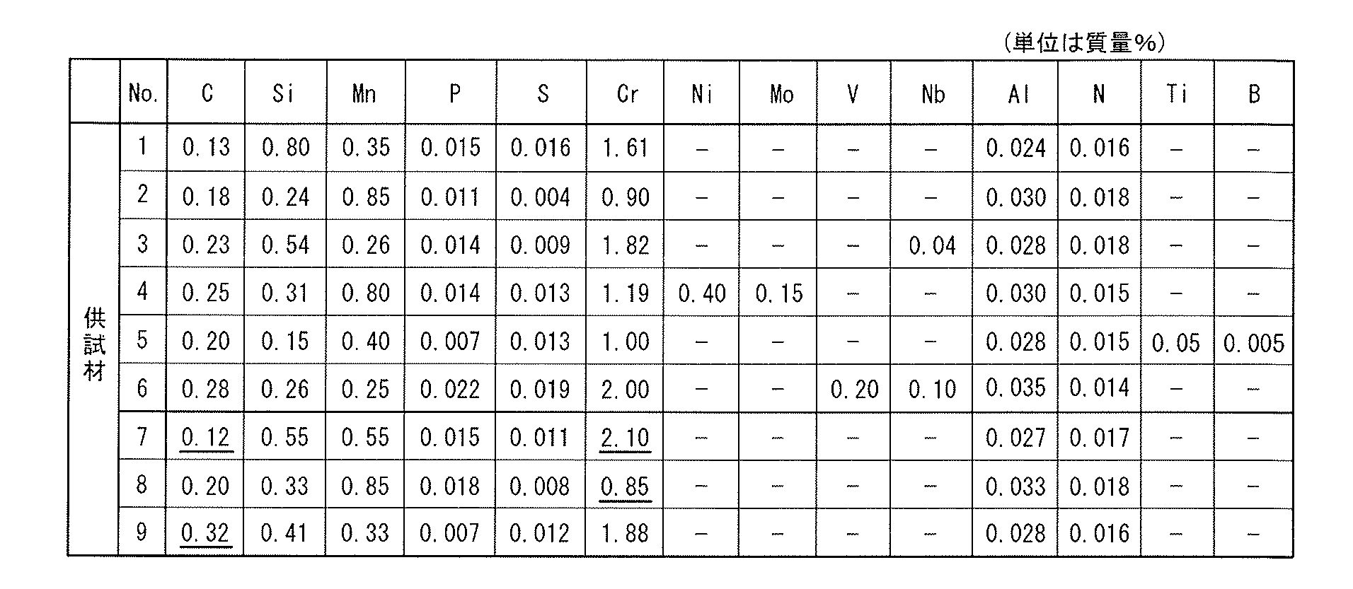
- test material No. Nos. 1 to 6 have the chemical components claimed in the present application.
- Test material No. 7 to 9 deviate from the chemical components of the present invention.
- Underlined numerical values indicate that the values fall outside the scope of the claims.
- "-" Indicates non-addition or impurity level.
- the roller pitching test piece (small roller) (1) shown in FIG. 6 was processed into a rough shape (rough processing).
- the finishing process of the test portion (2) is performed, and only the grip portion (3) is provided with an extra thickness of 0.2 mm for one side in order to perform the grinding finish after the subsequent heat treatment. did.
- a surplus thickness of 2 mm for one side was provided in order to perform processing for removing the carburized layer after the subsequent heat treatment except for the notch surface.
- test material No. shown in Table 1 was used.
- spheroidizing annealing maintained at the reheating temperature shown in Table 2 was performed.
- quenching was performed, and then, after holding at 180 ° C. for 1.5 hours, tempering was performed by air cooling, and a roller pitching test piece (small roller) (1) And Charpy impact test pieces.
- Reheat temperature means the spheroidizing annealing temperature and the final quenching temperature.
- the first digit value is 1 or 2 when the first digit value is 1 or 2, it means that the heat treatment condition defined in the claims of the present application is satisfied. Means out of the heat treatment conditions in the claims of the present application.
- the comparative steel part No. 71 in Table 2 has a 7th digit in the second digit, it has a component composition out of the component range of the present application, such as the test material No. 7 in Table 1. Since the value of the first digit is 1, it indicates that the treatment is performed under the heat treatment conditions within the scope of the claims of the present application. Therefore, it is of the component composition of Test Material No. 2, and the first digit is 3, which means that the treatment is performed under heat treatment conditions outside the scope of the claims of the present application.)
- roller pitching test piece small roller (1) shown in FIG. 6 and the large roller test piece shown in FIG. Using 4) and under the conditions shown in Table 3, the roller pitching test shown in FIG. 7 was performed.
- a slip ratio of -40% means that the peripheral speed of the large roller is 40% lower than the peripheral speed of the small roller.
- the ATF (Automatic Transmission Fluid) of lubricating oil means lubricating oil used for an automatic transmission of a vehicle.
- a large roller crowning amount of 150R means that the shape of the outer peripheral surface of the large roller in contact with the small roller in the rotation axis direction is a circular arc having a radius of 150 mm.
- the crystal grain size was investigated by cutting a roller pitching test piece (small roller) (1), which was completed up to the above tempering, into a test piece, and then using a resin so that the cross section from the surface layer to the inside could be observed. After embedding inside, perform mirror polishing of the test site, perform intergranular corrosion, and take an average visual field from the outermost surface to 0.3 mm below the surface with an optical microscope, The average crystal grain size (diameter) was determined.
- the treated surface is used as a surface layer as described above. Shall be observed.
- Comparative steel part No. No. 81 is the test material No. in Table 1. 8 is a steel corresponding to SCr420 specified in JIS. That is, each of the Nos.
- the Charpy impact value of the steel of Comparative Steel Part No. manufactured using steel corresponding to SCr420 It is shown as a relative ratio based on the value of the Charpy impact value of 81.
- the Charpy impact value ratio of the comparative steel part no. If it is 1.5 or more as compared with 81, it is determined that the toughness of the steel part is good.
- each No. of Table 4 The pitting resistance of the steel part of the comparative steel part was no.
- Table 4 shows the ratio when the number of cycles is set to 1 until the pitching of 81 occurs. At this time, if the cycle number ratio until the occurrence of pitting was 2.0 or more, the pitting resistance was determined to be good.
- the test material No. having the component composition shown in Table 1 was used. Using 1 to 7 (steel within the composition range of the present application), heating at a temperature of 850 to 1030 ° C. shown in Table 2 so that the surface layer has a carbon concentration of 0.8 to 1.5%. After cooling to 200 ° C. at 0.2 to 5.0 ° C./s, then reheating to 810 to 860 ° C. and holding, spheroidizing annealing and tempering at 150 ° C. Part No. 11 to 62.
- the carbide having an aspect ratio of 1.5 or less was formed of the steel material of the working steel part No. 11 to 62, 90 to 98%, which is 90% or more. That is, carbide having a large aspect ratio becomes a source of stress concentration due to its shape during deformation and becomes a starting point of crack initiation and reduces toughness.However, since there is little such carbide, toughness does not decrease and improves. ing.
- the test material No. In 1 to 7 (steel within the composition range of the present application), the spheroidized carbide 5 on the prior austenite grain boundaries having a grain size exceeding 1 ⁇ m is 3 to 7%, that is, the former austenite grains In the spheroidized carbide 5 on the boundary, 90% or more of the particle size was 1 ⁇ m or less.
- Carbides (especially network-like carbides along the grain boundaries) that precipitate and exist at the prior austenite grain boundaries are more likely to be fracture starting points and have higher harmfulness than the intragranular carbides. Carbides were reduced to 40% or less, and those with low harmfulness of 1 ⁇ m or less accounted for 90% or more.
- the actual steel part No. The prior austenite grain boundaries of 11 to 62 had a particle size of 4 to 8 ⁇ m.
- the former austenite grain size can be reduced in size by reducing the unit of fracture surface of grain boundary fracture or cleavage fracture, and the energy required for fracture can be increased, thereby improving toughness. Therefore, the steel part for machine structure using the steel of the present invention has improved toughness.
- the Charpy impact ratio where 81 was 1.0, was 1.6 to 2.5, indicating high toughness of 1.5 or more.
- the actual steel part No. 11 to 62 are comparative steel part numbers.
- the ratio of the number of cycles until the occurrence of pitting was 2.2 to 2.9, and the pitting resistance was good.
- the mechanical parts manufactured by the manufacturing method of the present invention are all excellent in pitting resistance and toughness.
Abstract
耐ピッチング特性と靱性に優れた機械部品1の製造方法は、質量%で、C:0.13~0.30%、Cr:0.90~2.00%を含有し、さらにSi、Mn、Ni、Mo、Nb、V、Ti、B、Al、Nのうち1種以上を含有し、残部がFeおよび不可避不純物からなる鋼材に対して、加熱温度850~1030℃に加熱し、表面の炭素濃度0.8~1.5%とする浸炭工程と、表面層3のAcm点(℃)より高い温度から、A1点(℃)よりも50℃以上低い温の冷却終了温度まで、平均5℃/sec以下の速度で冷却して分散されたパーライト組織もしくはベイナイト組織とする工程と、表面層3におけるAcm点(℃)以下の加熱温度での球状化焼なまし工程と、表面層3におけるAcm点(℃)以下に加熱し、焼戻しする工程とを含む。
Description
本発明は、高面圧が負荷される機械構造用鋼からなる部品に用いられる、耐ピッチング特性および靱性に優れる機械部品の製造方法に関する。
本出願は、2018年6月18日出願の日本出願第2018-115350号に基づく優先権を主張し、当該日本出願に記載された全ての記載内容を援用するものである。
機械部品、例えば、歯車やシャフトなどの高面圧を受ける部品は、鋼材を熱間鍛造、冷間鍛造、切削などの工法により部品形状に成形したのち、ガス浸炭や真空浸炭など浸炭処理を施してから使用に供されている。さらに必要に応じて、研削やショットピーニングなどの追加処理を施す場合がある。浸炭処理は鋼をオーステナイト化温度以上の高温に加熱することで、鋼に対する炭素の固溶限を高めた状態にしたのち、鋼部品の表面から炭素を内部に侵入させる処理である。
一般的には、浸炭により鋼部品の表面に0.7~0.8%の炭素を侵入させる。その後、浸炭温度から直接的に焼入れするか、浸炭温度から一般的な焼入れ温度まで冷却してから焼入れするか、もしくは、浸炭処理後にいったん冷却し再加熱してから焼入れする、といった処理手順での焼入れ、およびそれに続く焼戻しが行われる。
それとは対照的に、浸炭状態の鋼部品と同様の熱履歴のみを与えると、鋼中の炭素はオーステナイト中への固溶限の制限により、鋼中に固溶できないものが炭化物として鋼中に残存する。このような鋼中に残存した炭化物は、粒界に析出すると、靱性に対して悪影響がある。
近年、燃費の向上を目的とした、自動車などのトランスミッションに代表される駆動系ユニットの小型軽量化に伴い、歯車やシャフト類への負荷は益々増大する傾向にある。特に歯車では、歯面のピッチング発生による短寿命化や歯元折損の可能性がある。
これらの問題に対して、歯車の歯面の耐ピッチング性を高める技術として、準高温から高温においても分解しにくい炭化物、例えばFe3CであるセメンタイトやM23C6型の炭化物などを積極的に析出させて硬度を高め、焼戻し軟化抵抗性の向上を志向した高濃度浸炭法が提案されている(例えば、特許文献1参照。)。
鋼部品の表面の炭素濃度を1.2%以上の高濃度にすることで、炭化物を微細かつ大量に析出させ、さらに焼戻し軟化抵抗性の向上を志向する、高濃度浸炭法も提案されている(例えば、特許文献2参照。)。
これらの高濃度浸炭法は、粒界に粗大な炭化物が析出することにより、靱性に対する悪影響を及ぼすことが指摘されている(例えば、特許文献3および特許文献4参照。)。
特許文献3では、高濃度浸炭を行った後、パーライト変態を起こす冷却速度で空冷による徐冷を行って、表層の組織をパーライトと成し、しかる後にパーライト組織中のセメンタイトを細かく分断させることで、炭化物中に、1μm以下の炭化物が90%以上を占める微細炭化物として生じせしめる、加熱および冷却条件によって、高周波焼入れを行う製造方法が提案されている。
特許文献3では、高周波焼入れの短い時間でパーライト組織中の層状の細くかつ長く伸びたセメンタイトを分断させるので、アスペクト比が1.5以下の球状化セメンタイトの割合は低いものとなっている。靱性の観点からすると、いまだ十分なものとはいえないものであった。特許文献4による場合も、同様に靱性の点でいまだ十分とはいえなかった。
一方、特許文献5では、質量%で、Cの含有量が0.55~1.10%と、炭素を多く含有する鋼であって、焼入れ後の組織がマルテンサイト組織と球状化炭化物の二相組織からなり、全セメンタイトに占める球状化セメンタイト率や、旧オーステナイト粒界上のセメンタイト率を制御することによる高硬度かつ靱性に優れた鋼が提案されている。この鋼の炭素濃度は、浸炭法による処理を行った後の鋼部品の表面炭素濃度とほぼ同じである。ところが、この鋼では、鋼部品内部まで炭素濃度が高いために、浸炭法により処理された内部の炭素濃度が低い鋼部品に比べると、十分な靱性が得られない場合があるなど、硬度とのバランスをはかりつつも、さらにより靱性を高めることが求められている。
本願の発明が解決しようとする課題は、高面圧が負荷される部品として用いるための、耐ピッチング特性及び靱性に優れた機械部品の製造方法を提供することである。
上記の課題を解決するための本発明の第1の手段は、質量%で、C:0.13~0.30%、Cr:0.90~2.00%を含有し、さらにSi、Mn、Ni、Mo、Nb、V、Ti、B、Al、Nのうち1種以上を含有し、残部がFeおよび不可避不純物からなる鋼材で形成された素材を準備する工程と、
該素材に対して、加熱温度850~1050℃とし、該素材の表面層の炭素濃度が0.8~1.5%を満たすように該素材を浸炭する工程と、
該素材の表面層におけるAcm点(℃)より高い温度から、A1点(℃)よりも50℃以上低い温度である冷却終了温度までの温度範囲を平均5℃/sec以下の速度で冷却して、該表面層をパーライト組織もしくはベイナイト組織とする工程と、
該表面層におけるAcm点(℃)以下の加熱温度で球状化焼なましして該パーライト組織もしくは該ベイナイト組織の炭化物を球状化する工程と、
該素材の該表面層におけるAcm点(℃)以下に加熱してから焼入れし、次いで焼戻しする工程と、を経る機械部品の製造方法である。
本発明の第2の手段は、質量%で、C:0.13~0.30%、Cr:0.90~2.00%を含有し、さらにSi、Mn、Ni、Mo、Nb、V、Ti、B、Al、Nのうち1種以上を含有し、残部がFeおよび不可避不純物とする化学成分を有する鋼材を用いた機械部品であって、表面の炭素濃度が0.8~1.5%を満たすように浸炭され、さらに最表面を含む層である表面層における組織は球状化炭化物が分散するマルテンサイト組織及び残留オーステナイト組織から成り、アスペクト比が1.5以下の球状化炭化物が全炭化物の90%以上であり、旧オーステナイト粒界上の炭化物に関して、旧オーステナイト粒界上の球状化炭化物の個数が占める割合は全炭化物数の40%以下である機械部品の製造方法であり、
該化学成分の鋼材から形成された素材を準備する工程と、
該素材に対して、加熱温度を850~1030℃とし、該表面層の炭素濃度が0.8~1.5%を満たすように浸炭する工程と、
該表面層におけるAcm点(℃)より高い温度から、A1点(℃)よりも50℃以上低い温度である冷却終了温度までの温度範囲を平均5℃/sec以下の速度で冷却してパーライト組織もしくはベイナイト組織とする工程と、
該表面層におけるAcm点(℃)以下の加熱温度で球状化焼なましして該パーライト組織もしくはベイナイト組織中の炭化物を球状化する工程と、
該素材の該表面層におけるAcm点(℃)以下に加熱してから焼入れしてマルテンサイト組織を形成し、次いで焼戻しする工程と、を経る機械部品の製造方法である。
本発明の第3の手段は、さらに旧オーステナイト粒界上の該球状化炭化物は、その大きさの90%以上が粒径1μm以下である機械部品である前記第2の手段に記載の機械部品の製造方法である。
本発明の第4の手段は、さらに旧オーステナイト粒界は平均粒径の大きさが15μm以下である機械部品である前記第3の手段に記載の機械部品の製造方法である。
本発明の手段に記載の製造方法によると、上記手段に記載の鋼材を用いて高面圧が負荷される機械部品に用いるための耐ピッチング特性および靱性に優れる機械部品を製造することができる。
発明を実施するための形態を記載するに先立って、本願における浸炭処理前の機械構造用鋼の鋼材の化学成分の限定の理由および本願の発明における工程の限定の理由について説明する。
C:0.13~0.30%
Cは、鋼部品の芯部の焼入性、鍛造性および機械加工性に影響する元素である。そして、Cが0.13%未満では十分な芯部の硬さが得られず、強度が低下するので、Cは0.13%以上の添加が必要であり、望ましくは、0.16%以上の添加がよい。一方、Cは、多いと、素材の硬さを増加し、被削性および鍛造性などの加工性を阻害する元素であるから、Cが過多になると、素材の芯部硬さが過剰となり、靭性が劣化する。そこで、Cは0.30%以下にする必要があり、望ましくは0.28%以下にするとよい。したがって、Cは0.13~0.30%とし、望ましくは0.16~0.28%とする。
Cは、鋼部品の芯部の焼入性、鍛造性および機械加工性に影響する元素である。そして、Cが0.13%未満では十分な芯部の硬さが得られず、強度が低下するので、Cは0.13%以上の添加が必要であり、望ましくは、0.16%以上の添加がよい。一方、Cは、多いと、素材の硬さを増加し、被削性および鍛造性などの加工性を阻害する元素であるから、Cが過多になると、素材の芯部硬さが過剰となり、靭性が劣化する。そこで、Cは0.30%以下にする必要があり、望ましくは0.28%以下にするとよい。したがって、Cは0.13~0.30%とし、望ましくは0.16~0.28%とする。
Cr:0.90~2.00%
Crは、焼入性を向上させる元素であり、また、球状化焼なましによる炭化物の球状化を容易にする元素である。これらの効果を得るためには、Crは0.90%以上が必要であり、望ましくは1.00%以上とするとよい。一方、Crは、過剰に添加するとセメンタイトが脆くなり、靭性を劣化させる元素である。また、Crは多いと、浸炭阻害を起こし、素材硬さの低減につながるほか、浸炭時に粗大炭化物を形成し、耐ピッチング性の低下につながる元素である。そこで、Crは2.00%以下にする必要があり、望ましくは1.90%以下にするとよい。したがって、Crの含有量は0.90~2.00%とし、望ましくは1.50%より大きく1.90%以下とする。
Crは、焼入性を向上させる元素であり、また、球状化焼なましによる炭化物の球状化を容易にする元素である。これらの効果を得るためには、Crは0.90%以上が必要であり、望ましくは1.00%以上とするとよい。一方、Crは、過剰に添加するとセメンタイトが脆くなり、靭性を劣化させる元素である。また、Crは多いと、浸炭阻害を起こし、素材硬さの低減につながるほか、浸炭時に粗大炭化物を形成し、耐ピッチング性の低下につながる元素である。そこで、Crは2.00%以下にする必要があり、望ましくは1.90%以下にするとよい。したがって、Crの含有量は0.90~2.00%とし、望ましくは1.50%より大きく1.90%以下とする。
本発明の製造方法により耐ピッチング特性と靱性に優れる機械部品を得るためには、炭化物の形状と分布の制御が重要となる。炭化物は、主体がセメンタイト(Fe3C)であり、更に、M23C6型炭化物(主にCr23C6)、(FeCr)3Cを含んでもよい。炭化物の主要構成元素はFe、Cr、Cであることから、CとCrが炭化物の形状や分布に大きく影響する。そこで、本発明では、鋼に添加されるCとCrの成分について、上記のとおり規定している。
他方、他の添加元素については、本発明において重要な炭化物の形成や分布に関しては、CやCrほどには影響を大きく与えるものではない。そこで、以下の選択的成分については、機械構造用肌焼き鋼として一般的な添加量であれば適用できる。
(選択的成分)
Si、Mn、Ni、Mo、Nb、V、Ti、B、Al、Nのうち1種以上
Si、Mn、Ni、Mo、Nb、V、Ti、B、Al、Nについては、要求される用途に応じて、そのうち1種以上を選択して使用する元素である。
(選択的成分)
Si、Mn、Ni、Mo、Nb、V、Ti、B、Al、Nのうち1種以上
Si、Mn、Ni、Mo、Nb、V、Ti、B、Al、Nについては、要求される用途に応じて、そのうち1種以上を選択して使用する元素である。
なお、これらの成分が選択的成分として添加される場合には、たとえば、以下のような範囲であることが望ましい。
Siを含有する場合は0.15~0.80%が望ましい。
Siは、鋼部品の焼戻し軟化抵抗性を高め、ピッチング特性向上にも有効な元素である。さらに、Si添加量が0.15%以上になると、粒界酸化深さが低減するので、ピッチング特性の向上には、Siは0.15%以上である必要がある。一方、Siは多いと、浸炭阻害を起こし、耐ピッチング強度劣化につながる元素である。そこで、Siは0.80%以下にする必要がある。
Mnを含有する場合は0.90%以下が望ましい。
Mnは、多いと靭性を低下させる元素である。そこで、Mnは0.90%以下にする必要がある。
Pは0.030%以下が望ましい。
Pは、鋼中に不可避的に含有される不純物元素であり、粒界に偏析し、靭性を劣化させる元素である。そこで、Pは0.030%以下にする必要がある。
Sは0.030%以下が望ましい。
Sは、鋼中に不可避的に含有される不純物元素であり、Mnと結びついてMnSを形成し、靭性を劣化させる元素である。そこで、Sは0.030%以下にする必要がある。P、Sなどを含めた不可避不純物の総量は1.0%未満に規制することが望ましい。
Alを含有する場合は0.020%以上が望ましい。
Alは、Nと結合してAlNを生成するため、結晶粒の粗大化の抑制に有効な元素である。結晶粒の粗大化は、靱性を劣化させる。そこで、Alは0.020%以上にする必要がある。
Nを含有する場合は0.008%以上が望ましい。
Nは、鋼中でAl窒化物やNb窒化物といった窒化物として微細に析出し、鋼部品の靭性などの強度を低下させる要因となる結晶粒の粗大化の抑制に有効な元素である。その効果を得るためには、Nは0.008%以上にする必要がある。
Ni、Mo、VやBは靭性を向上させるためには有効な元素である。
Bを含有する場合は、Tiを0.01~0.05%とすることが望ましい。
Tiは、B添加時に、Bによる焼入性の改善効果を発揮させる元素である。その焼入性の改善のためには、窒素とTiを結合させてTi窒化物を形成させる必要がある。そこで、Tiを0.01%以上添加する。なお、このTiの添加量はNの添加量の3.4倍以上であることが望ましい。
Nbを含有する場合は0.01~0.10%が望ましい。
Nbは、浸炭時に炭化物または炭窒化物を形成し、結晶粒を微細化させるのに有効な元素である。また、Nbは結晶粒を微細化することで、粒界酸化の深さを浅くするとともに、粒界酸化となるき裂が生成した際にもき裂長さが短くなる。しかし、Nbが0.01%未満では、き裂長さが小さくなる効果は得られない。一方、Nbは0.10%を超えると結晶粒微細化の効果は飽和する。
本発明の製造方法の素材材料に用いられる鋼材は、質量%で、C:0.13~0.30%、Cr:0.90~2.00%を含有し、さらにSi、Mn、Ni、Mo、Nb、V、Ti、B、Al、Nのうち1種以上を含有し、残部がFeおよび不可避不純物からなる。
本発明の機械部品は、以下の各工程を含む手順にて製造することができる。手順の一例を、時間と処理温度の関係を示す線として図1に模式的に示す。
(i)鋼材より機械部品形状の素材を準備する工程と、
(ii)素材に対し、加熱温度850~1050℃とし、素材の表面層の炭素濃度が質量%で0.8~1.5%を満たすように浸炭する工程と、
(iii)素材の表面層におけるAcm点(℃)より高い温度から、A1点(℃)よりも50℃以上低い温度である冷却終了温度までの温度範囲を平均5℃/sec以下の速度で冷却してパーライト組織もしくはベイナイト組織とする工程と、
(iv)素材の表面層におけるAcm点(℃)以下の加熱温度で球状化焼なましする工程と、
(v)素材の表面層におけるAcm点(℃)以下に加熱してから焼入れし、次いで焼戻しする工程を含む。
(i)鋼材より機械部品形状の素材を準備する工程と、
(ii)素材に対し、加熱温度850~1050℃とし、素材の表面層の炭素濃度が質量%で0.8~1.5%を満たすように浸炭する工程と、
(iii)素材の表面層におけるAcm点(℃)より高い温度から、A1点(℃)よりも50℃以上低い温度である冷却終了温度までの温度範囲を平均5℃/sec以下の速度で冷却してパーライト組織もしくはベイナイト組織とする工程と、
(iv)素材の表面層におけるAcm点(℃)以下の加熱温度で球状化焼なましする工程と、
(v)素材の表面層におけるAcm点(℃)以下に加熱してから焼入れし、次いで焼戻しする工程を含む。
以下にこれらの工程の理由を個別に説明する。
図2に処理工程のフローチャートを示す。
(i) 鋼材より機械部品形状の素材を準備する工程
鋼材を鍛造などで粗成形し、機械加工により目的の機械部品と同じ形状の素材を成形する。機械部品1の一例の歯車断面を図3および図4に示す。素材は、以下の工程を経て、機械部品1とされる。
(ii) 素材に対し、加熱温度を850~1050℃とし、素材の表面層の炭素濃度が0.8~1.5%を満たすように浸炭する工程
工程(ii)を経た素材は、芯部4と、芯部4の表面を被覆する浸炭層2と、より構成される。浸炭層2は、素材の表面側に表面層3を持つ。表面層3は最表面から少なくとも0.3mmの深さをもつ。本願の工程の効果を得るためには、加熱温度はAcm点(℃)より高い温度である必要がある。素材の加熱温度が高いほど、短時間で所定の炭素濃度まで浸炭することができる。素材の加熱温度が高すぎると加熱炉の寿命を低下させる。そこで、素材の加熱温度を850~1050℃とする。
素材の表面層3の炭素濃度が0.8%未満では、目的とする炭化物を十分に析出させることができにくい。一方、素材の表面層3の炭素濃度が1.5%を超えると、オーステナイト粒界上にアスペクト比が1.5を超える炭化物を形成し、靭性が低下する。そこで、表面層3の炭素濃度を0.8~1.5%を満たすように浸炭する。
炭素濃度が低いほど靱性の観点から好ましく、高いほど硬さの観点から好ましいことから、双方のバランスをはかって、表面層3の炭素濃度は、0.85~1.20%であれば、更に好ましい。
表面層3の炭素濃度とは、素材の表面から0.3mmの深さまでの範囲の領域での平均炭素濃度を意味する。浸炭の方法は、ガス浸炭、真空浸炭あるいは浸炭窒化のいずれかによる方法でもよい。
なお、冷却の際にはそれに続く工程で処理するか、いったん任意に冷却し、再度所定の加熱温度まで加熱した後、それに続く工程で処理するかは、どちらでも良い。
(iii) 表面層3におけるAcm点(℃)より高い温度から、A1点(℃)よりも50℃以上低い温度である冷却終了温度までの温度範囲を平均5℃/sec以下の速度で冷却する工程
本願の工程の効果を得るためには、炭化物を適度な大きさおよび適度な面積率で分布しておく必要がある。そのためには、浸炭後に、焼入れすることなく部品素材をいったん冷却した後、所定の熱処理を行う必要がある。
(iii) 表面層3におけるAcm点(℃)より高い温度から、A1点(℃)よりも50℃以上低い温度である冷却終了温度までの温度範囲を平均5℃/sec以下の速度で冷却する工程
本願の工程の効果を得るためには、炭化物を適度な大きさおよび適度な面積率で分布しておく必要がある。そのためには、浸炭後に、焼入れすることなく部品素材をいったん冷却した後、所定の熱処理を行う必要がある。
上記の工程とする理由は、浸炭中に部品素材中に過飽和に固溶したCの一部を、炭化物として析出させるためである。冷却後の表面層の組織はパーライト組織もしくはベイナイト組織より成る。
そこでこれらの温度領域間での冷却速度を、平均5℃/sec以下とする。平均5℃/secよりも速い冷却速度で冷却された場合は、マルテンサイトが生成することにより、炭化物が過飽和に固溶したまま冷却されるため、それに続く工程で十分な大きさの炭化物が殆ど析出せず、かつ析出しても微細に留まるため、炭化物の成長が不十分であり、所望の靭性や耐ピッチング性が得られないこととなる。
本工程の冷却をする際には、いったん室温まで冷却するか、図1に示されるように表面層3におけるA1点を下回った後に、それに続く工程へと進めるかは、どちらでもよい。
(iv) 素材の表面層3におけるAcm点(℃)以下の加熱温度で球状化焼なましする工程
本願の工程の効果を得るためには、炭化物を適度な大きさに成長させ、適度な面積率で分布しておく必要がある。そのためには、Acm点(℃)以下の加熱温度で球状化焼なましする必要がある。なお、Acm点とは、加熱時、過共析鋼中の炭化物が完全に溶解する温度のことである。
(iv) 素材の表面層3におけるAcm点(℃)以下の加熱温度で球状化焼なましする工程
本願の工程の効果を得るためには、炭化物を適度な大きさに成長させ、適度な面積率で分布しておく必要がある。そのためには、Acm点(℃)以下の加熱温度で球状化焼なましする必要がある。なお、Acm点とは、加熱時、過共析鋼中の炭化物が完全に溶解する温度のことである。
上記の工程とする理由は、仮に、表面層3にAcm点(℃)以上の加熱温度で、球状化焼なましを行うと、炭化物が全て素材中に固溶してしまうために、本願の工程の効果を得ることができないからである。
なお、本工程の冷却をする際には、いったん室温まで冷却するか、Ar1点を下回った後に、それに続く工程に進めるかは、どちらでもかまわない。
(v) 素材の表面層3におけるAcm点(℃)以下に加熱してから焼入れし、次いで焼戻しする工程
本願の工程の効果を得るためには、炭化物を適度な大きさに成長させ、適度な面積率で分布しておく必要がある。また、機械部品1として使用可能な硬さを得る必要がある。そのために、熱処理炉で再加熱してから焼入れすることが必要である。
(v) 素材の表面層3におけるAcm点(℃)以下に加熱してから焼入れし、次いで焼戻しする工程
本願の工程の効果を得るためには、炭化物を適度な大きさに成長させ、適度な面積率で分布しておく必要がある。また、機械部品1として使用可能な硬さを得る必要がある。そのために、熱処理炉で再加熱してから焼入れすることが必要である。
そこで、上記の工程とする理由は、表面層5におけるAcm点(℃)を超える加熱温度で焼入を行うと、炭化物が素材中に固溶してしまうために、本願の工程の効果を得ることができないからである。したがって加熱温度はできるだけ低い方が望ましい。一方で、加熱温度が低すぎると、機械部品1の芯部領域において、芯部が完全にオーステナイト化せず部分的に軟質なフェライトが残存し、疲労強度が低下するため、芯部のAr3点(℃)よりも高い温度で焼入を行うのが望ましい。
さて、上記の工程を含む製造方法で得られる機械部品のさらなる特性について以下に詳述する。
(A) 表面層3は球状化炭化物5が分散したマルテンサイト組織7及び残留オーステナイト組織7から成り、アスペクト比が1.5以下の球状化炭化物5が全炭化物の90%以上の機械部品1が得られること
球状化炭化物5の長径/短径の比で定義するアスペクト比は、球状化の指標である。そして、アスペクト比が大きな形状の、例えば板状あるいは柱状に近い形状の炭化物は、その形状に起因して変形時に応力集中源となり、さらに、き裂発生の起点となって靭性を低下させる。そこで、靭性向上の観点から、炭化物は球状に近いことが望ましい。そして、球状化炭化物5のアスペクト比が1.5以下であれば、き裂発生の起点となる有害性を下げることができる。
そこで、アスペクト比が1.5以下の球状化炭化物5の割合が大きいほど好ましい。本発明の製造方法によると、アスペクト比が1.5以下の球状化炭化物5は全炭化物数の90%以上を得ることができ、さらに望ましくは95~100%とすることもできる。
(B) 旧オーステナイト粒界6上の炭化物に関して、旧オーステナイト粒界6上の球状化炭化物の個数が占める割合は全炭化物数の40%以下とできること
本発明の手段の鋼材の成分組成は、浸炭による機械部品の表面領域における炭素濃度からみて過共析の範囲である。そして、過共析鋼において耐衝撃特性を劣化させる脆性破壊の形態は、主に旧オーステナイト粒界5に沿った粒界破壊である。この原因となるのは、旧オーステナイト粒界6上の炭化物、すなわち特に粒界に沿った編目上の炭化物、であり、この粒界に析出して存在する炭化物は粒内の炭化物よりも破壊の起点となり易くかつ有害性が高い。したがって、このような炭化物が粒界上に存在すると好ましくない。そこで、本発明の製造方法により、旧オーステナイト粒界上の球状化炭化物の個数が占める割合は全炭化物の40%以下とすることができる。また、望ましくは20%以下、さらに望ましくは5%以下から0%とすることもできる。
本発明の手段の鋼材の成分組成は、浸炭による機械部品の表面領域における炭素濃度からみて過共析の範囲である。そして、過共析鋼において耐衝撃特性を劣化させる脆性破壊の形態は、主に旧オーステナイト粒界5に沿った粒界破壊である。この原因となるのは、旧オーステナイト粒界6上の炭化物、すなわち特に粒界に沿った編目上の炭化物、であり、この粒界に析出して存在する炭化物は粒内の炭化物よりも破壊の起点となり易くかつ有害性が高い。したがって、このような炭化物が粒界上に存在すると好ましくない。そこで、本発明の製造方法により、旧オーステナイト粒界上の球状化炭化物の個数が占める割合は全炭化物の40%以下とすることができる。また、望ましくは20%以下、さらに望ましくは5%以下から0%とすることもできる。
(C) 旧オーステナイト粒界6上の球状化炭化物5は、粒径の大きさの90%以上が粒径1μm以下とできること
炭化物が旧オーステナイト粒界上に存在することは好ましくない。特に、粒界に沿った網目状の炭化物やそれに類似するような粗大な炭化物は粒界破壊の起点となる危険が増加する。本発明によると、球状化炭化物5は、有害性の低い粒径1μm以下の粒径の大きさのものが90%以上とできる。さらに、望ましくは95~100%とすることもできる。
炭化物が旧オーステナイト粒界上に存在することは好ましくない。特に、粒界に沿った網目状の炭化物やそれに類似するような粗大な炭化物は粒界破壊の起点となる危険が増加する。本発明によると、球状化炭化物5は、有害性の低い粒径1μm以下の粒径の大きさのものが90%以上とできる。さらに、望ましくは95~100%とすることもできる。
なお、ここでいう%とは、走査型電子顕微鏡の5000倍程度で観察できる炭化物の全個数を100%とした時の割合である。上記の倍率で観察できない非常に微細な炭化物は靭性に与える影響が小さいため考慮しない。図5では、旧オーステナイト粒界上の球状化炭化物は大きさが小さいため、表れておらず、図示されていない。
(D) 旧オーステナイト粒界6は、粒径の大きさが15μm以下であること
旧オーステナイト粒界6の差渡しの大きさである粒径Aは、微細化することで、粒界破壊もしくはへき開破壊の破面単位を小さくすることができ、破壊に要するエネルギーを大きくすることができるので、靭性を向上させることができる。そこで、結晶粒径の微細化は硬度を下げることなく靭性を向上させる方法として非常に有効である。
(D) 旧オーステナイト粒界6は、粒径の大きさが15μm以下であること
旧オーステナイト粒界6の差渡しの大きさである粒径Aは、微細化することで、粒界破壊もしくはへき開破壊の破面単位を小さくすることができ、破壊に要するエネルギーを大きくすることができるので、靭性を向上させることができる。そこで、結晶粒径の微細化は硬度を下げることなく靭性を向上させる方法として非常に有効である。
本願の製造方法は、その微細な炭化物を析出させた状態で最終の焼入れを行い、その際、比較的低温で焼入れを行うことによって、旧オーステナイト粒界6の粒径Aを微細に維持することができる。
なお、一方、旧オーステナイト粒界6の粒径Aが15μmを超えると、靱性を向上させる効果が小さくなる。特に、浸炭時の加熱温度を1050℃以上にすることは、たとえ最終の焼入れを行ったとしても、旧オーステナイト粒界6を粗くしてしまう。そこで、旧オーステナイト粒界6の粒径Aは、大きさが15μm以下とできることが有用である。
次いで、発明を実施するための形態について、実施例を用いて説明する。なお、化学成分における、%は質量%である。
表1に示す化学成分を有し、残部がFeおよび不可避不純物からなる鋼を、100kg真空溶解炉で溶製した。これらの鋼を1250℃で、直径32mmの棒鋼に鍛伸した後、925℃で1時間の焼ならしを行った。
供試材のうち、供試材No.1~6は本願請求範囲の化学成分を有する。供試材No.7~9は本願請求範囲の化学成分から外れる。下線を付した数値は、本願請求範囲から外れることを示す。「-」は、非添加もしくは不純物レベルであることを示す。
そして、図6に示すローラーピッチング試験片(小ローラー)(1)の粗形に加工(粗加工)した。この粗加工の際には、試験部(2)の仕上げ加工を実施しており、つかみ部(3)のみ、以降の熱処理後に研削仕上げを行うために、片肉0.2mmの余肉を付与した。また、10RCノッチのシャルピー衝撃試験片(1)の粗形に加工した。粗加工の際には、ノッチ面以外について以降の熱処理後に浸炭層を除去する加工を行うために片肉2mmの余肉を付与した。
実施鋼部品No.および比較鋼部品No.の数値の2桁目の値は、表1の供試材No.の成分組成に相当することを意味している。
(たとえば表2の実施鋼部品No.11およびNo.12は2桁目の値が1であるから、表1の供試材No.1の成分組成のものに対する熱処理条件を示すものであり、表2の実施鋼部品No.21およびNo.22は、2桁目の数値が2であるから、表1の供試材No.2の成分組成のものに対する熱処理条件を示している。)
また、表2における実施鋼部品No.および比較鋼部品No.の数値の1桁目の値は、1桁目の値が1ないし2の場合は、本願請求範囲の熱処理条件を充足している場合を意味しており、1桁目が3ないし4の場合は本願請求範囲の熱処理条件から外れることを意味している。
(たとえば、表2の比較鋼部品No.71は、2桁目の数値が7であるから、表1の供試材No.7のように本願の成分範囲から外れた成分組成のものを、1桁目の値が1であるから、本願請求範囲内の熱処理条件で処理していることを示している。また、表2の比較鋼部品No.23は、2桁目の値が2であるから、供試材No.2の成分組成のものであって、1桁目が3であるから、本願請求範囲から外れた熱処理条件で処理していることを意味している。)


なお、結晶粒度の調査は、上記の焼戻しまでを完了したローラーピッチング試験片(小ローラー)(1)を切断して試片とし、表層から内部にかけての断面が観察できるようにこの試片を樹脂中に埋込を行ってから、被検部位の鏡面研磨を行ない、粒界腐食を行ってから、光学顕微鏡により最表面から表面下0.3mmまでの範囲にかけての平均的な視野を撮影し、平均結晶粒径(直径)を求めた。
また、炭化物の観察については、上記と同様に試片を樹脂中に埋込みを行なってから、被検部位の鏡面研磨の後、ナイタールで腐食し、走査型電子顕微鏡により最表面から表面下0.3mmまでの範囲にかけての平均的な視野を撮影し、図5に示す炭化物を識別して示すミクロ組織の画像を得た。識別した炭化物について、画像解析により炭化物のアスペクト比が1.5以下の炭化物率(%)、旧オーステナイト粒界上の炭化物の個数率(%)、旧オーステナイト粒界上の粒径1μm超えの炭化物率(%)、旧オーステナイト粒界の平均粒径(μm)をそれぞれ確認した。
なお、焼戻し後に、切削、研削、研磨、ショットブラスト、ショットピーニング、ハードショットピーニング、微粒子ショットピーニングのいずれか1種または複数種の表面処理を行う場合には、その処理面を表層として上記と同様の観察を行うものとする。
上記の試験結果を表4に示す。シャルピー衝撃値と耐ピッチング性は、比較鋼部品No.81を基準とした。比較鋼部品No.81は、表1の供試材No.8の成分組成であり、これはJIS規定のSCr420に相当する鋼である。すなわち、表4の各No.の鋼のシャルピー衝撃値は、SCr420に相当する鋼を用いて製造した比較鋼部品No.81のシャルピー衝撃値の値を基準として相対的な比として示したものである。そして、シャルピー衝撃値比が比較鋼部品No.81に比して1.5以上を示すならば、その鋼部品の靭性は良好であるとした。
また、表4の各No.の鋼部品の耐ピッチング性は、比較鋼部品のNo.81のピッチング発生までの、サイクル数を1としたときの比でもって、表4に示している。このとき、ピッチング発生までのサイクル数比が2.0以上あれば、耐ピッチング性が良好であるとした。

このとき、表4に示すように、まず、アスペクト比が1.5以下の炭化物が実施鋼部品No.11~62では90~98%と、90%以上を示した。すなわち、アスペクト比の大きな炭化物は、変形時に、その形状に起因して応力集中源となり、き裂発生の起点となり靭性を低下させるが、そうした炭化物が少ないことから、靱性が低下せず、向上している。
また、実施鋼部品No.11~62について、旧オーステナイト粒界上の球状化炭化物5の個数が占める割合は全炭化物数の11~40%で、40%以下となった。また、供試材No.1~7(本願の成分組成範囲内の鋼)では、粒径の大きさが粒径1μmを超えた旧オーステナイト粒界上の球状化炭化物5は3~7%であり、すなわち、旧オーステナイト粒界上の球状化炭化物5は、粒径の大きさの90%以上が粒径1μm以下であった。旧オーステナイト粒界に析出して存在する炭化物(特に粒界に沿った網目状の炭化物)は、粒内の炭化物よりも破壊の起点となり易くかつ有害性が高いところ、本発明では粒界上の炭化物が40%以下に低減されており、有害性が小さい1μm以下のものが90%以上を占めた。
また、実施鋼部品No.11~62の旧オーステナイト粒界は粒径の大きさは、4~8μmであった。旧オーステナイト粒径は、微細化することで、粒界破壊もしくはへき開破壊の破面単位を小さくすることができ、破壊に要するエネルギーを大きくすることができるため、靭性を向上させることができるのであるから、本発明鋼を用いた機械構造用鋼部品は、靱性が向上している。
そして、実施鋼部品No.11~62は、比較鋼部品No.81を1.0としたシャルピー衝撃比が1.6~2.5であり、1.5以上と高い靱性を示した。
同様に、実施鋼部品No.11~62は、比較鋼部品No.81を1.0とした場合のピッチング発生までのサイクル数の比が、2.2~2.9を示し、耐ピッチング性が良好であった。
このように、本発明の製造方法で製造された機械部品は、いずれも耐ピッチング特性と靱性に優れるものとなる。
今回開示された実施の形態および実施例はすべての点で例示であって、どのような面からも制限的なものではないと理解されるべきである。本発明の範囲は上記した説明ではなく、請求の範囲によって規定され、請求の範囲と均等の意味および範囲内でのすべての変更が含まれることが意図される。
1 歯車(機械部品)、2 浸炭層、3 表面層、4 芯部、5 球状化セメンタイト(球状化炭化物)、6 旧オーステナイト粒界、7 マルテンサイト組織または残留オーステナイト組織、8 ローラーピッチング試験片(小ローラー)、9 試験部、10 つかみ部、11 大ローラー試験片、A 粒径。
Claims (4)
- 質量%で、C:0.13~0.30%、Cr:0.90~2.00%を含有し、さらにSi、Mn、Ni、Mo、Nb、V、Ti、B、Al、Nのうち1種以上を含有し、残部がFeおよび不可避不純物からなる鋼材で形成された素材を準備する工程と、該素材に対して、加熱温度を850~1050℃とし、該素材の表面層の炭素濃度が0.8~1.5%を満たすように該素材を浸炭する工程と、
該表面層におけるAcm点(℃)より高い温度から、A1点(℃)よりも50℃以上低い温度である冷却終了温度までの温度範囲を平均5℃/sec以下の速度で冷却して、該表面層をパーライト組織もしくはベイナイト組織とする工程と、
該素材の該表面層におけるAcm点(℃)以下の加熱温度で球状化焼なましして該パーライト組織若しくは該ベイナイト組織中の炭化物を球状化する工程と、
該素材の該表面層におけるAcm点(℃)以下に加熱してから焼入れし、次いで焼戻しする工程と、
を経る機械部品の製造方法。 - 質量%で、C:0.13~0.30%、Cr:0.90~2.00%を含有し、さらにSi、Mn、Ni、Mo、Nb、V、Ti、B、Al、Nのうち1種以上を含有し、残部がFeおよび不可避不純物とする化学成分を有する鋼材を用いた機械部品であって、表面の炭素濃度が0.8~1.5%を満たすように浸炭され、さらに最表面を含む層である表面層の組織は球状化炭化物が分散するマルテンサイト組織及び残留オーステナイト組織から成り、アスペクト比が1.5以下の該球状化炭化物が全炭化物の90%以上であり、旧オーステナイト粒界上の炭化物に関して、旧オーステナイト粒界上の該球状化炭化物の個数が占める割合は全炭化物数の40%以下である該機械部品の製造方法であり、
該化学成分の該鋼材から形成された素材を準備する工程と、
該素材に対して、加熱温度を850~1050℃とし、該素材の表面の炭素濃度が0.8~1.5%を満たすように浸炭して該素材表面に表面層を形成する工程と、
該表面層におけるAcm点(℃)より高い温度から、A1点(℃)よりも50℃以上低い温度である冷却終了温度までの温度範囲を平均5℃/sec以下の速度で冷却してパーライト組織もしくはベイナイト組織とする工程と、
該素材の該表面層におけるAcm点(℃)以下の加熱温度で球状化焼なましして該パーライト組織若しくは該ベイナイト組織中の炭化物を球状化する工程と、
該素材の該表面層におけるAcm点(℃)以下に加熱してから焼入れしてマルテンサイト組織を形成し、次いで焼戻しする工程、
を経る機械部品の製造方法。 - 該旧オーステナイト粒界上の該球状化炭化物は、粒径の大きさの90%以上が粒径1μm以下である、請求項2に記載の機械部品の製造方法。
- 該旧オーステナイト粒界の粒径が15μm以下である、請求項3に記載の機械部品の製造方法。
Priority Applications (4)
| Application Number | Priority Date | Filing Date | Title |
|---|---|---|---|
| US17/046,087 US11326220B2 (en) | 2018-06-18 | 2019-05-10 | Method for producing machine component |
| AU2019287841A AU2019287841B2 (en) | 2018-06-18 | 2019-05-10 | Method for producing machine components |
| CN201980041164.XA CN112313350B (zh) | 2018-06-18 | 2019-05-10 | 机械部件的制造方法 |
| DE112019001853.1T DE112019001853T5 (de) | 2018-06-18 | 2019-05-10 | Verfahren zum Herstellen eines Maschinenbauteils |
Applications Claiming Priority (2)
| Application Number | Priority Date | Filing Date | Title |
|---|---|---|---|
| JP2018115350A JP7270343B2 (ja) | 2018-06-18 | 2018-06-18 | 機械部品の製造方法 |
| JP2018-115350 | 2018-06-18 |
Publications (1)
| Publication Number | Publication Date |
|---|---|
| WO2019244504A1 true WO2019244504A1 (ja) | 2019-12-26 |
Family
ID=68983716
Family Applications (1)
| Application Number | Title | Priority Date | Filing Date |
|---|---|---|---|
| PCT/JP2019/018694 WO2019244504A1 (ja) | 2018-06-18 | 2019-05-10 | 機械部品の製造方法 |
Country Status (6)
| Country | Link |
|---|---|
| US (1) | US11326220B2 (ja) |
| JP (1) | JP7270343B2 (ja) |
| CN (1) | CN112313350B (ja) |
| AU (1) | AU2019287841B2 (ja) |
| DE (1) | DE112019001853T5 (ja) |
| WO (1) | WO2019244504A1 (ja) |
Families Citing this family (2)
| Publication number | Priority date | Publication date | Assignee | Title |
|---|---|---|---|---|
| CN112695269B (zh) * | 2020-11-30 | 2022-09-27 | 山西平阳重工机械有限责任公司 | 一种18Cr2Ni4WA工件的热处理工艺 |
| US20230407425A1 (en) * | 2022-05-31 | 2023-12-21 | Schaeffler Technologies AG & Co. KG | Treatment method and process for valve seat |
Citations (7)
| Publication number | Priority date | Publication date | Assignee | Title |
|---|---|---|---|---|
| JPS6224499B2 (ja) * | 1978-11-20 | 1987-05-28 | Komatsu Mfg Co Ltd | |
| JPH02156063A (ja) * | 1988-12-08 | 1990-06-15 | Mazda Motor Corp | 浸炭焼入れ方法 |
| JPH06108226A (ja) * | 1992-09-30 | 1994-04-19 | Daido Steel Co Ltd | 鋼製部品の浸炭熱処理方法 |
| JP2005154784A (ja) * | 2002-11-12 | 2005-06-16 | Daido Steel Co Ltd | 耐食性に優れた軸受鋼 |
| WO2011132722A1 (ja) * | 2010-04-19 | 2011-10-27 | 新日本製鐵株式会社 | 焼戻し軟化抵抗性に優れた鋼部品 |
| CN105239017A (zh) * | 2015-10-19 | 2016-01-13 | 燕山大学 | 一种渗碳轴承钢及其制备方法 |
| JP2016156037A (ja) * | 2015-02-23 | 2016-09-01 | 大同特殊鋼株式会社 | 高濃度浸炭鋼の製造方法 |
Family Cites Families (11)
| Publication number | Priority date | Publication date | Assignee | Title |
|---|---|---|---|---|
| JPH0559527A (ja) | 1991-08-27 | 1993-03-09 | Sumitomo Metal Ind Ltd | 耐摩耗性及び転動疲労性に優れた鋼の製造法 |
| JP2002348615A (ja) | 2001-05-18 | 2002-12-04 | Daido Steel Co Ltd | 耐高面圧部材およびその製造方法 |
| US20040094238A1 (en) | 2002-11-12 | 2004-05-20 | Koyo Seiko Co., Ltd. | Bearing steel excellent in corrosion resistance |
| JP4188307B2 (ja) | 2004-12-10 | 2008-11-26 | 大同特殊鋼株式会社 | 浸炭部品及びその製造方法 |
| KR100633522B1 (ko) * | 2005-05-27 | 2006-10-13 | 주식회사 성도 | 대형 선박용 캠의 열처리 방법 |
| JP5305820B2 (ja) * | 2008-10-08 | 2013-10-02 | アイシン・エィ・ダブリュ株式会社 | 浸炭部品の製造方法及び鋼部品 |
| KR101671133B1 (ko) | 2010-01-27 | 2016-10-31 | 제이에프이 스틸 가부시키가이샤 | 표면 경화강 및 침탄재 |
| JP6432932B2 (ja) | 2014-09-01 | 2018-12-05 | 山陽特殊製鋼株式会社 | 耐ピッチング性および耐摩耗性に優れる高強度高靱性機械構造用鋼製部品およびその製造方法 |
| JP6703385B2 (ja) | 2015-09-18 | 2020-06-03 | 国立大学法人大阪大学 | 高硬度かつ靭性に優れた鋼 |
| CN105714190B (zh) * | 2016-04-29 | 2017-10-20 | 燕山大学 | 一种耐冲击载荷轴承用钢及其热处理方法 |
| CN106756755B (zh) * | 2016-12-12 | 2018-10-02 | 中车戚墅堰机车车辆工艺研究所有限公司 | 大型挖掘机齿轮的渗碳淬火方法 |
-
2018
- 2018-06-18 JP JP2018115350A patent/JP7270343B2/ja active Active
-
2019
- 2019-05-10 US US17/046,087 patent/US11326220B2/en active Active
- 2019-05-10 CN CN201980041164.XA patent/CN112313350B/zh active Active
- 2019-05-10 WO PCT/JP2019/018694 patent/WO2019244504A1/ja active Application Filing
- 2019-05-10 DE DE112019001853.1T patent/DE112019001853T5/de active Pending
- 2019-05-10 AU AU2019287841A patent/AU2019287841B2/en active Active
Patent Citations (7)
| Publication number | Priority date | Publication date | Assignee | Title |
|---|---|---|---|---|
| JPS6224499B2 (ja) * | 1978-11-20 | 1987-05-28 | Komatsu Mfg Co Ltd | |
| JPH02156063A (ja) * | 1988-12-08 | 1990-06-15 | Mazda Motor Corp | 浸炭焼入れ方法 |
| JPH06108226A (ja) * | 1992-09-30 | 1994-04-19 | Daido Steel Co Ltd | 鋼製部品の浸炭熱処理方法 |
| JP2005154784A (ja) * | 2002-11-12 | 2005-06-16 | Daido Steel Co Ltd | 耐食性に優れた軸受鋼 |
| WO2011132722A1 (ja) * | 2010-04-19 | 2011-10-27 | 新日本製鐵株式会社 | 焼戻し軟化抵抗性に優れた鋼部品 |
| JP2016156037A (ja) * | 2015-02-23 | 2016-09-01 | 大同特殊鋼株式会社 | 高濃度浸炭鋼の製造方法 |
| CN105239017A (zh) * | 2015-10-19 | 2016-01-13 | 燕山大学 | 一种渗碳轴承钢及其制备方法 |
Also Published As
| Publication number | Publication date |
|---|---|
| JP7270343B2 (ja) | 2023-05-10 |
| DE112019001853T5 (de) | 2020-12-31 |
| AU2019287841B2 (en) | 2022-03-17 |
| US11326220B2 (en) | 2022-05-10 |
| AU2019287841A1 (en) | 2020-12-17 |
| CN112313350A (zh) | 2021-02-02 |
| JP2019218583A (ja) | 2019-12-26 |
| US20210032716A1 (en) | 2021-02-04 |
| CN112313350B (zh) | 2022-06-28 |
Similar Documents
| Publication | Publication Date | Title |
|---|---|---|
| JP5927868B2 (ja) | 冷間鍛造性に優れた浸炭用鋼およびその製造方法 | |
| KR101464712B1 (ko) | 템퍼링 연화 저항성이 우수한 강 부품 | |
| WO2019244503A1 (ja) | 機械部品 | |
| JP6461478B2 (ja) | 高周波焼入れ歯車及び歯車の高周波焼入れ方法 | |
| JP6432932B2 (ja) | 耐ピッチング性および耐摩耗性に優れる高強度高靱性機械構造用鋼製部品およびその製造方法 | |
| JP4464862B2 (ja) | 耐結晶粒粗大化特性と冷間加工性に優れた軟化焼鈍の省略可能な肌焼用鋼 | |
| JP2007308772A (ja) | 浸炭部品およびその製造方法 | |
| JP6950821B2 (ja) | 機械部品とその製造方法 | |
| WO2019244504A1 (ja) | 機械部品の製造方法 | |
| JP2000129347A (ja) | 高強度部品の製造方法 | |
| JP6601358B2 (ja) | 浸炭部品およびその製造方法 | |
| JP2002212672A (ja) | 鋼部材 | |
| JP4488228B2 (ja) | 高周波焼入れ用鋼材 | |
| JP4757831B2 (ja) | 高周波焼入れ部品およびその製造方法 | |
| JPH10147814A (ja) | 熱処理歪みの少ない肌焼鋼製品の製法 | |
| JP6680406B1 (ja) | 機械部品及び機械部品の製造方法 | |
| JP4821582B2 (ja) | 真空浸炭歯車用鋼 | |
| JPH08260039A (ja) | 浸炭肌焼鋼の製造方法 | |
| JP5969204B2 (ja) | 耐摩耗性と面疲労特性に優れた高周波焼入歯車およびその製造方法 | |
| JP6551225B2 (ja) | 高周波焼入れ歯車 | |
| JP2021028414A (ja) | 浸炭歯車用鋼、浸炭歯車及び浸炭歯車の製造方法 | |
| JP7368697B2 (ja) | 浸炭歯車用鋼、浸炭歯車及び浸炭歯車の製造方法 | |
| JP2005220377A (ja) | 球状化後の冷間鍛造性に優れた肌焼用鋼線材・棒鋼 |
Legal Events
| Date | Code | Title | Description |
|---|---|---|---|
| 121 | Ep: the epo has been informed by wipo that ep was designated in this application |
Ref document number: 19821640 Country of ref document: EP Kind code of ref document: A1 |
|
| ENP | Entry into the national phase |
Ref document number: 2019287841 Country of ref document: AU Date of ref document: 20190510 Kind code of ref document: A |
|
| 122 | Ep: pct application non-entry in european phase |
Ref document number: 19821640 Country of ref document: EP Kind code of ref document: A1 |