WO2019235271A1 - 配置装置および配置方法 - Google Patents
配置装置および配置方法 Download PDFInfo
- Publication number
- WO2019235271A1 WO2019235271A1 PCT/JP2019/020775 JP2019020775W WO2019235271A1 WO 2019235271 A1 WO2019235271 A1 WO 2019235271A1 JP 2019020775 W JP2019020775 W JP 2019020775W WO 2019235271 A1 WO2019235271 A1 WO 2019235271A1
- Authority
- WO
- WIPO (PCT)
- Prior art keywords
- performance
- resource consumption
- predicted
- hardware
- unit
- Prior art date
- Legal status (The legal status is an assumption and is not a legal conclusion. Google has not performed a legal analysis and makes no representation as to the accuracy of the status listed.)
- Ceased
Links
Images


Classifications
-
- G—PHYSICS
- G06—COMPUTING OR CALCULATING; COUNTING
- G06F—ELECTRIC DIGITAL DATA PROCESSING
- G06F11/00—Error detection; Error correction; Monitoring
- G06F11/30—Monitoring
- G06F11/34—Recording or statistical evaluation of computer activity, e.g. of down time, of input/output operation ; Recording or statistical evaluation of user activity, e.g. usability assessment
- G06F11/3452—Performance evaluation by statistical analysis
-
- G—PHYSICS
- G06—COMPUTING OR CALCULATING; COUNTING
- G06F—ELECTRIC DIGITAL DATA PROCESSING
- G06F11/00—Error detection; Error correction; Monitoring
- G06F11/30—Monitoring
- G06F11/34—Recording or statistical evaluation of computer activity, e.g. of down time, of input/output operation ; Recording or statistical evaluation of user activity, e.g. usability assessment
- G06F11/3409—Recording or statistical evaluation of computer activity, e.g. of down time, of input/output operation ; Recording or statistical evaluation of user activity, e.g. usability assessment for performance assessment
-
- G—PHYSICS
- G06—COMPUTING OR CALCULATING; COUNTING
- G06F—ELECTRIC DIGITAL DATA PROCESSING
- G06F11/00—Error detection; Error correction; Monitoring
- G06F11/30—Monitoring
- G06F11/34—Recording or statistical evaluation of computer activity, e.g. of down time, of input/output operation ; Recording or statistical evaluation of user activity, e.g. usability assessment
- G06F11/3409—Recording or statistical evaluation of computer activity, e.g. of down time, of input/output operation ; Recording or statistical evaluation of user activity, e.g. usability assessment for performance assessment
- G06F11/3419—Recording or statistical evaluation of computer activity, e.g. of down time, of input/output operation ; Recording or statistical evaluation of user activity, e.g. usability assessment for performance assessment by assessing time
-
- G—PHYSICS
- G06—COMPUTING OR CALCULATING; COUNTING
- G06F—ELECTRIC DIGITAL DATA PROCESSING
- G06F11/00—Error detection; Error correction; Monitoring
- G06F11/30—Monitoring
- G06F11/34—Recording or statistical evaluation of computer activity, e.g. of down time, of input/output operation ; Recording or statistical evaluation of user activity, e.g. usability assessment
- G06F11/3409—Recording or statistical evaluation of computer activity, e.g. of down time, of input/output operation ; Recording or statistical evaluation of user activity, e.g. usability assessment for performance assessment
- G06F11/3419—Recording or statistical evaluation of computer activity, e.g. of down time, of input/output operation ; Recording or statistical evaluation of user activity, e.g. usability assessment for performance assessment by assessing time
- G06F11/3423—Recording or statistical evaluation of computer activity, e.g. of down time, of input/output operation ; Recording or statistical evaluation of user activity, e.g. usability assessment for performance assessment by assessing time where the assessed time is active or idle time
-
- G—PHYSICS
- G06—COMPUTING OR CALCULATING; COUNTING
- G06F—ELECTRIC DIGITAL DATA PROCESSING
- G06F11/00—Error detection; Error correction; Monitoring
- G06F11/30—Monitoring
- G06F11/34—Recording or statistical evaluation of computer activity, e.g. of down time, of input/output operation ; Recording or statistical evaluation of user activity, e.g. usability assessment
- G06F11/3466—Performance evaluation by tracing or monitoring
-
- G—PHYSICS
- G06—COMPUTING OR CALCULATING; COUNTING
- G06F—ELECTRIC DIGITAL DATA PROCESSING
- G06F30/00—Computer-aided design [CAD]
- G06F30/30—Circuit design
- G06F30/32—Circuit design at the digital level
- G06F30/33—Design verification, e.g. functional simulation or model checking
-
- G—PHYSICS
- G06—COMPUTING OR CALCULATING; COUNTING
- G06F—ELECTRIC DIGITAL DATA PROCESSING
- G06F9/00—Arrangements for program control, e.g. control units
- G06F9/06—Arrangements for program control, e.g. control units using stored programs, i.e. using an internal store of processing equipment to receive or retain programs
- G06F9/46—Multiprogramming arrangements
- G06F9/50—Allocation of resources, e.g. of the central processing unit [CPU]
-
- G—PHYSICS
- G06—COMPUTING OR CALCULATING; COUNTING
- G06N—COMPUTING ARRANGEMENTS BASED ON SPECIFIC COMPUTATIONAL MODELS
- G06N20/00—Machine learning
Definitions
- the present invention relates to an arrangement device and an arrangement method.
- Non-patent document 1 a technique for improving the performance of the entire system by combining hardware (hereinafter also referred to as a device) has been studied.
- Non-Patent Literature 2-4
- the present invention has been made in view of the above, and an object thereof is to quickly arrange network functions on a plurality of types of hardware.
- the arrangement device includes resource consumption and performance information representing the performance of each of a plurality of types of hardware that are candidates for function arrangement.
- a storage unit that stores statistical information, a reception unit that receives input of description contents of a function in a high-level language that is a hardware description language corresponding to a plurality of types of hardware, and a performance requirement that represents required performance; For each piece of hardware, using the description content and a predetermined algorithm, a prediction unit that calculates a predicted performance that is a predicted performance and a predicted resource consumption that is a predicted resource consumption, and the calculated Hardware whose predicted performance and the performance information satisfy the performance requirements and whose total value of the predicted resource consumption and the resource consumption is less than the resource capacity is allocated.
- a selection unit for selecting as previously in that it comprises the features.
- network functions can be quickly arranged on a plurality of types of hardware.
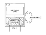
- FIG. 1 is an explanatory diagram for explaining a target system of the placement apparatus according to the present embodiment.
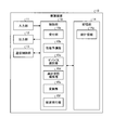
- FIG. 2 is a schematic view illustrating a schematic configuration of the arrangement device.
- FIG. 3 is a diagram illustrating a data configuration of statistical information.
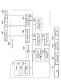
- FIG. 4 is an explanatory diagram for explaining processing of the placement apparatus.
- FIG. 5 is a flowchart illustrating the arrangement processing procedure.
- FIG. 6 is a diagram illustrating a computer that executes an arrangement program.
- FIG. 1 is an explanatory diagram for explaining a target system of the placement apparatus according to the present embodiment.
- a system that is a target of placement processing by the placement device is configured by incorporating an accelerator into a server.
- the accelerator is realized by hardware of a different type from the CPU of the server such as NP (Network Processor) or FPGA (Field Programmable Gate Array).
- traffic of packets received by the accelerator from other network devices in the communication network is distributed to the CPU of the accelerator or server according to processing required for the packets.
- the accelerator is provided with a network function that becomes a load factor of the CPU of the server. Thereby, it becomes possible to offload the CPU load of the server to the accelerator.
- the placement apparatus executes placement processing for determining whether to place each network function in a CPU or an accelerator in such a system.
- FIG. 2 is a schematic view illustrating the schematic configuration of the placement device 10.
- the placement apparatus 10 of the present embodiment is realized by a general-purpose computer such as a workstation or a personal computer, and includes an input unit 11, an output unit 12, a communication control unit 13, a storage unit 14, and a control unit 15. Is provided.
- the input unit 11 is realized by using an input device such as a keyboard or a mouse, and inputs various instruction information such as processing start to the control unit 15 in response to an input operation by the operator.
- the output unit 12 is realized by a display device such as a liquid crystal display, a printing device such as a printer, an information communication device, or the like.
- the communication control unit 13 controls communication with an external device such as a network device via a telecommunication line such as a LAN (Local Area Network) or the Internet.
- the communication control unit 13 receives performance measurement values and the like for hardware such as a CPU, NP, or FPGA from the arrangement target system illustrated in FIG.
- the storage unit 14 is realized by a semiconductor memory device such as a RAM (Random Access Memory) or a flash memory, or a storage device such as a hard disk or an optical disk.
- the storage unit 14 may be configured to communicate with the control unit 15 via an electric communication line such as a LAN or the Internet.
- the storage unit 14 stores statistical information 14a.
- the statistical information 14a is information including resource consumption and performance information representing the performance of each of a plurality of types of hardware that are candidates for function placement.
- FIG. 3 is a diagram illustrating a data configuration of the statistical information 14a.
- the statistical information 14a includes resource consumption and performance information for each device.
- CPU, FPGA1, FPGA2, etc. are illustrated as devices.
- Resource consumption is an actual value represented by the usage rate (%) of each device.
- the resource consumption amount further includes detailed information that differs for each device.
- the CPU resource consumption shown in FIG. 3 includes the number of cores, the number of cores used, the number of memories, the memory usage, and the like.
- the resource consumption of FPGA 1 includes the number of FFs (flip-flops) and the FF usage.
- the amount, the number of LUTs (lookup tables), the amount of LUT used, and the like are included.
- Performance information is actual values including throughput (Gbps), delay (ms), and the like.
- the throughput is the amount of data that each device can process within a certain time.
- the delay is expressed, for example, by the time from when a packet is transmitted until the receiving side transmits an ACK packet to the transmitting side and when the transmitting side receives the ACK packet.
- the statistical information 14a includes a status and a function used.
- the status is information indicating whether or not each device can be used, and is represented by “operation” or “failure”.
- the placement apparatus 10 selects a device whose status is “active” as a placement destination of the network function in a placement process to be described later.
- the function used is represented by the function arranged in each device and the actual value of resource consumption by each function.
- the placement device 10 converts the source code of the high-level language into the source code of the device selected as the placement destination of the network function in the placement processing described later, and measures the resource consumption of the function using the converted source code.
- the statistical information 14a is updated using this measured value as the actual value.
- the “resource consumption amount” described above corresponds to the total value of resource consumption amounts of all “used functions” arranged in each device.
- the control unit 15 is executed by a CPU or the like and executes a processing program stored in a memory. As illustrated in FIG. 2, the reception unit 15a, the performance prediction unit 15b, the device selection unit 15c, the high-level language editing unit 15d, and the conversion Functions as the unit 15e and the arrangement execution unit 15f.
- the accepting unit 15a accepts input of a function description content in a high-level language, which is a hardware description language corresponding to a plurality of types of hardware, and a performance requirement representing a required performance. Specifically, the accepting unit 15a requests the source code described in the high-level language of the function to be arranged and the performance such as throughput and delay via the input unit 11 or the communication control unit 13. Accepts performance requirements that are conditions.
- a high-level language which is a hardware description language corresponding to a plurality of types of hardware
- a performance requirement representing a required performance.
- the accepting unit 15a requests the source code described in the high-level language of the function to be arranged and the performance such as throughput and delay via the input unit 11 or the communication control unit 13. Accepts performance requirements that are conditions.
- the performance prediction unit 15b functions as a prediction unit.
- the performance prediction unit 15b uses, for each hardware, the predicted content that is the predicted processing performance and the predicted resource consumption that is the predicted resource consumption by using the description content of the high-level language and the predetermined algorithm. And calculate.
- the performance prediction unit 15b generates an algorithm by learning using the description content of the high-level language and the resource consumption and performance information measured for the function corresponding to the description content.
- the performance prediction unit 15b uses the source code of the high-level language of the function and the resource consumption and performance information of the statistical information 14a as the actual value for this function, and the source code of the high-level language and each Learn the relationship between hardware resource consumption and performance information. Thereby, the performance prediction unit 15b generates an algorithm for calculating the relationship between the source code of the high-level language, the resource consumption of each hardware, and the performance information.
- the performance prediction unit 15b stores the generated algorithm in the storage unit 14.
- the performance predicting unit 15b applies the generated algorithm to each hardware, and predicts the predicted performance, that is, the predicted performance, from the source code of the high-level language of the function input as the target of the placement process.
- the resource consumption, that is, the predicted resource consumption is calculated.
- the device selection unit 15c functions as a selection unit. That is, the device selection unit 15c selects, as the placement destination, hardware in which the calculated predicted performance and performance information satisfy the performance requirements and the total value of the predicted resource consumption and the resource consumption is equal to or less than the resource capacity. .
- the device selection unit 15c compares the input performance requirement, the calculated predicted performance, and the performance information of the statistical information 14a on the hardware for each hardware. Then, the device selection unit 15c sets this hardware as a placement destination candidate when both the predicted performance and the performance information satisfy the performance requirements.
- the device selection unit 15c calculates the total value of the calculated resource predicted resource consumption and the resource consumption of the statistical information 14a. Then, when the calculated total value is equal to or less than the resource capacity of this hardware, the device selection unit 15c selects this hardware as a function placement destination.
- FIG. 4 is an explanatory diagram for explaining the processing of the placement apparatus 10.
- the device selection unit 15c includes a selection function unit and a comparison function unit. Then, the selection function unit sequentially designates a target device for processing for determining whether or not the function is an appropriate location for the performance prediction unit 15b.
- the selection function unit first refers to the initial arrangement information that is input in advance via the input unit 11 or the communication control unit 13 and stored in the storage unit 14, and is designated by the initial arrangement information. To the device selection unit 15c as the first target device.
- the selection function unit of the device selection unit 15c functions as the reception unit 15a, receives the high-level language source code of the function input as the target of the arrangement process, and transfers it to the performance prediction unit 15b.
- the performance prediction unit 15b calculates the prediction performance and the predicted resource consumption for the specified device using the source code and algorithm of the high-level language, and transfers the result to the comparison function unit of the device selection unit 15c as the prediction result. .
- This algorithm is generated by the performance prediction unit 15b in advance using the source code of the high-level language of the function and the resource consumption and performance information of the statistical information 14a as the actual value for this function.
- the comparison function unit of the device selection unit 15c functions as the reception unit 15a and receives performance requirements.
- the comparison function unit compares the input performance requirement, the prediction result, and the performance information and resource consumption of the statistical information 14a for this device.
- the comparison function unit when the calculated predicted performance and performance information satisfy the performance requirements, and the total value of the predicted resource consumption and the resource consumption of the device is within the range of the resource capacity of the device, As the determination result OK, this device is selected as the placement destination.
- the comparison function unit instructs the selection function unit to change the target device as the determination result NG.
- the selection function unit sequentially designates the target device as the placement destination of the placement process to the performance prediction unit 15b.
- the target device designation order is not particularly limited.
- the target device designation order may be designated in ascending order of resource consumption, that is, in order from the largest resource allowable amount obtained by subtracting the device resource consumption from the device resource capacity.
- the comparison function unit instructs the selection function unit to change the target device as the determination result NG.
- the selection function unit changes the target device to FPGA1.
- the delay of the FPGA 1 is 1 ms and the throughput is 40 Gbps, which satisfies the performance requirement. Therefore, if the predicted performance satisfies the performance requirements and the total value of the predicted resource consumption and the resource consumption is equal to or less than the resource capacity of the device, the selection function unit determines the FPGA 1 as the function placement destination.
- the resource consumption of FPGA1 is 10%, the predicted resource consumption is 20%, and the resource capacity is 100%, the total of the predicted resource consumption and the resource consumption is equal to or less than the resource capacity. As determined. In this case, the resource consumption of the FPGA 1 after arrangement is 30%. In this case, the resource consumption of the CPU does not change.
- comparison function unit of the device selection unit 15c further refers to the status of the statistical information 14a and confirms that the target device has not failed, and then determines the placement destination.
- the arrangement apparatus 10 can predict resource consumption and performance information by function using the source code in the high-level language of the function to be arranged. For this reason, it is possible to quickly and appropriately select the hardware at which the function is to be arranged, without performing simulations or checking the operation with an actual machine.
- the high-level language editing unit 15d functions as an editing unit. That is, the high-level language editing unit 15d divides the description content in the high-level language when the resource allowable amount, which is a value obtained by subtracting the resource consumption amount from the hardware resource capacity, is smaller than the predicted resource consumption amount. Further, when the resource allowable amount is larger than the predicted resource consumption amount, the high-level language editing unit 15d combines the description contents in the high-level language of a plurality of functions within the range of the resource allowable amount.
- the conversion unit 15e converts the source code in a high-level function language into source code corresponding to hardware.
- the arrangement execution unit 15f measures statistical information using a source code corresponding to hardware.
- the high-level language editing unit 15d uses the source code of the high-level language of the function targeted for the arrangement process or other Editing such as combining with the source code of the function.
- the high-level language editing unit 15d passes the edited source code to the device selection unit 15c.
- the device selection unit 15c changes the function described in the edited source code to the target of the arrangement process, and performs the subsequent process.
- the conversion unit 15e converts the source code in the high-level language of the function received from the device selection unit 15c into the source code of the determined device. Delivered to the placement execution unit 15f.
- the placement execution unit 15f executes function simulation or operation check on the actual machine using the source code converted by the conversion unit 15e. And the arrangement
- the performance prediction unit 15b uses the updated statistical information 14a to generate an algorithm used for performance prediction and updates the algorithm in the storage unit 14. This improves the accuracy of the algorithm.
- FIG. 5 is a flowchart illustrating the arrangement processing procedure.
- the flowchart in FIG. 5 is started, for example, at a timing when the user instructs to start.
- the placement apparatus acquires performance information such as device type, delay, and throughput from each device (step S1), and stores it in the storage unit 14 as statistical information 14a (step S2). Further, the placement apparatus acquires the resource consumption amount of each device (step S3).
- the receiving unit 15a receives the input of the source code in the high-level language of the function to be arranged and the performance requirement (Step S4).
- the reception unit 15a receives input of delay requirements and throughput requirements as performance requirements.
- the selection function unit of the device selection unit 15c confirms that the initial arrangement information has been input (step S6), and if it has been input (step S6, Yes), the device of the initial arrangement information is arranged. It is confirmed that it exists as a destination (step S7).
- the selection function unit selects this device as a target device for placement processing (step S8).
- the selection function unit registers the statistical information 14a. Based on the number i, the target device for the placement process is selected (step S9).
- the selection function unit transfers the information specifying the selected device and the source code of the high-level language to the performance prediction unit 15b (step S10).
- the performance prediction unit 15b calculates the predicted resource consumption and the predicted performance (step S21), and outputs the calculated prediction result to the comparison function unit of the device selection unit 15c (step S22).
- predicted values of delay and throughput are output to the comparison function unit as predicted performance corresponding to performance requirements.
- the comparison function unit confirms that the performance requirements have been entered.
- the comparison function unit first confirms that the delay requirement is input (step S31), and if it is input (step S31, Yes), whether the delay of the prediction result and the statistical information 14a satisfies the delay requirement. It is confirmed whether or not (step S32).
- the comparison function unit proceeds to Step S33, and when not satisfied (No at Step S32), performs the process at Step S36. Proceed.
- step S33 the comparison function unit confirms that the throughput requirement has been input, and if it is input (step S33, Yes), whether the throughput of the prediction result and the statistical information 14a satisfies the throughput requirement. It is confirmed whether or not (step S34).
- step S34 the comparison function unit proceeds to Step S35, and when not satisfied (No at Step S34), performs the process at Step S36. Proceed.
- step S35 the comparison function unit checks whether the total value of the predicted resource consumption of the prediction result and the resource consumption of the statistical information 14a is within an allowable range equal to or less than the resource capacity of this device. When the total value is not within the allowable range (No at Step S35), the comparison function unit proceeds to Step S36. When the total value is within the allowable range (Yes at Step S35), the comparison function unit selects this device as the function placement destination. Then, the process proceeds to step S37.
- step S36 the comparison function unit increments the registration number i for identifying the device of the statistical information 14a, and returns the process to step S9.
- step S37 the comparison function unit notifies the conversion unit 15e of the device selected as the function placement destination and the source code of the high-level language, and instructs the execution of the compiler process (step S37).
- the conversion unit 15e executes a compiler process for converting the source code of the high-level language into the source code of the device at the placement destination, and delivers it to the placement execution unit 15f.
- the placement execution unit 15f places the compiler-processed function on the device (step S41), measures the resource consumption of the placed function (step S42), and uses the measured value as the actual value to obtain the statistical information 14a. Update. As a result, a series of arrangement processing ends.
- the storage unit 14 includes statistics including resource consumption and performance information representing performance of each of a plurality of types of hardware that are candidates for function arrangement destinations.
- Information 14a is stored.
- the accepting unit 15a accepts input of function description contents in a high-level language, which is a hardware description language corresponding to a plurality of types of hardware, and performance requirements representing required performance.
- the performance prediction unit 15b calculates, for each hardware, a predicted performance that is a predicted performance and a predicted resource consumption that is a predicted resource consumption by using the description content and a predetermined algorithm. To do.
- the device selection unit 15c satisfies the performance requirements of the calculated predicted performance and the performance information of the statistical information 14a, and the total value of the calculated predicted resource consumption and the resource consumption of the statistical information 14a is equal to or less than the resource capacity. Is selected as the placement destination.
- the arrangement apparatus 10 can predict the resource consumption and performance information by the function using the source code in the high-level language of the function to be arranged. For this reason, it is possible to quickly and appropriately select the hardware at which the function is to be arranged, without performing simulations or checking the operation with an actual machine. Therefore, according to the arrangement processing of the arrangement apparatus 10, it is possible to quickly arrange the network functions on a plurality of types of hardware.
- the performance prediction unit 15b generates an algorithm by learning using the description content in the high-level language and the resource consumption and performance information measured corresponding to the description content. This improves the accuracy of the algorithm used for performance prediction.
- the high-level language editing unit 15d divides the description content in the high-level language when the resource allowable amount, which is a value obtained by subtracting the resource consumption amount from the hardware resource capacity, is smaller than the predicted resource consumption amount, and the resource allowable amount is When it is larger than the predicted resource consumption, the description contents of a plurality of functions in a high-level language are combined within the range of the resource allowable amount. Thereby, it becomes possible to arrange network functions more appropriately.
- the arrangement apparatus 10 can be implemented by installing an arrangement program for executing the above arrangement processing as package software or online software on a desired computer.
- the information processing apparatus can be caused to function as the arrangement apparatus 10 by causing the information processing apparatus to execute the above arrangement program.
- the information processing apparatus referred to here includes a desktop or notebook personal computer.
- the information processing apparatus includes mobile communication terminals such as smartphones, mobile phones and PHS (Personal Handyphone System), and slate terminals such as PDA (Personal Digital Assistants).
- the placement device 10 can be implemented as a server device that uses a terminal device used by a user as a client and provides the client with services related to the placement processing.
- the arrangement apparatus 10 is implemented as a server apparatus that provides an arrangement processing service that receives performance requirements and source code of a function in a high-level language and outputs hardware at the function arrangement destination.
- the arrangement device 10 may be implemented as a Web server, or may be implemented as a cloud that provides services related to the above arrangement processing by outsourcing.
- a computer that executes an arrangement program that implements the same function as the arrangement apparatus 10 will be described.
- FIG. 6 is a diagram illustrating an example of a computer that executes an arrangement program.
- the computer 1000 includes, for example, a memory 1010, a CPU 1020, a hard disk drive interface 1030, a disk drive interface 1040, a serial port interface 1050, a video adapter 1060, and a network interface 1070. These units are connected by a bus 1080.
- the memory 1010 includes a ROM (Read Only Memory) 1011 and a RAM 1012.
- the ROM 1011 stores a boot program such as BIOS (Basic Input Output System).
- BIOS Basic Input Output System
- the hard disk drive interface 1030 is connected to the hard disk drive 1031.
- the disk drive interface 1040 is connected to the disk drive 1041.
- a removable storage medium such as a magnetic disk or an optical disk is inserted into the disk drive 1041.
- a mouse 1051 and a keyboard 1052 are connected to the serial port interface 1050.
- a display 1061 is connected to the video adapter 1060.
- the hard disk drive 1031 stores, for example, an OS 1091, an application program 1092, a program module 1093, and program data 1094. Each piece of information described in the above embodiment is stored in, for example, the hard disk drive 1031 or the memory 1010.
- the arrangement program is stored in the hard disk drive 1031 as a program module 1093 in which a command executed by the computer 1000 is described, for example.
- a program module 1093 describing each process executed by the placement apparatus 10 described in the above embodiment is stored in the hard disk drive 1031.
- data used for information processing by the arrangement program is stored as program data 1094 in, for example, the hard disk drive 1031.
- the CPU 1020 reads the program module 1093 and the program data 1094 stored in the hard disk drive 1031 to the RAM 1012 as necessary, and executes the above-described procedures.
- program module 1093 and the program data 1094 related to the arrangement program are not limited to being stored in the hard disk drive 1031, but are stored in, for example, a removable storage medium and read out by the CPU 1020 via the disk drive 1041 or the like. May be.
- the program module 1093 and the program data 1094 related to the arrangement program are stored in another computer connected via a network such as a LAN (Local Area Network) or a WAN (Wide Area Network), and via the network interface 1070. It may be read by the CPU 1020.
- LAN Local Area Network
- WAN Wide Area Network
Landscapes
- Engineering & Computer Science (AREA)
- Theoretical Computer Science (AREA)
- General Engineering & Computer Science (AREA)
- Physics & Mathematics (AREA)
- General Physics & Mathematics (AREA)
- Computer Hardware Design (AREA)
- Quality & Reliability (AREA)
- Software Systems (AREA)
- Evolutionary Computation (AREA)
- Computer Vision & Pattern Recognition (AREA)
- Artificial Intelligence (AREA)
- Data Mining & Analysis (AREA)
- Medical Informatics (AREA)
- Computing Systems (AREA)
- Mathematical Physics (AREA)
- Geometry (AREA)
- Life Sciences & Earth Sciences (AREA)
- Bioinformatics & Cheminformatics (AREA)
- Bioinformatics & Computational Biology (AREA)
- Evolutionary Biology (AREA)
- Probability & Statistics with Applications (AREA)
- Debugging And Monitoring (AREA)
Abstract
記憶部(14)が、機能の配置先の候補である複数種のハードウェアのそれぞれのリソース消費量と性能を表す性能情報とを含む統計情報(14a)を記憶し、受付部(15a)が、複数種のハードウェアに対応したハードウェア記述言語である高位言語による機能の記述内容と、要求される性能を表す性能要件との入力を受け付け、性能予測部(15b)が、ハードウェアごとに、記述内容と所定のアルゴリズムとを用いて、予測される性能である予測性能と、予測されるリソース消費量である予測リソース消費量とを算出し、デバイス選択部(15c)が、算出された予測性能および性能情報が性能要件を満たし、かつ予測リソース消費量とリソース消費量との合計値がリソース容量以下であるハードウェアを、配置先として選択する。
Description
本発明は、配置装置および配置方法に関する。
キャリアネットワークにおいて、トラヒックの増加に伴って、サーバのCPU(Central Processing Unit)のパケット処理負荷が増加している。そこで、サーバのCPU負荷をオフロードするため、CPUとは異なるハードウェア種別のアクセラレータをサーバと組み合わせて、ネットワーク機能(以下、単に機能とも記す。)の処理を分散させる技術が知られている(非特許文献1参照)。このように、ハードウェア(以下、デバイスとも記す。)を組み合わせて、システム全体の性能の向上を図る技術が検討されている。
その場合に、アクセラレータに使用するハードウェアプロセッサによって、システムのアーキテクチャの特徴やネットワーク機能の実現手法が異なる。そこで、これらの違いを隠蔽して機能開発を効率化するために、抽象度を高めて複数種のデバイスに対応したハードウェア記述言語であるP4等の高位言語が提案されている(非特許文献2~4参照)。
また、アクセラレータを1つのネットワーク機能で占有するとリソースに無駄が生じるため、アクセラレータには複数の機能を配置することが望ましい。そして、システム全体の性能向上を図るためには、複数種のハードウェアを組み合わせたシステム構成が必要である。
J.F.Zazo, et al., "A PCIe DMA engine to support the virtualization of 40 Gbps FPGA-accelerated network appliances", inReconfigurableComputing and FPGAs, pp.1-6, 2015年
「P4/CによるSmartNICファームウェア開発の取組み」、[online]、2017年、富士通、[2018年5月11日検索]、インターネット<URL:https://www.okinawaopenlabs.com/ood/2017/wp-content/uploads/sites/4/2017/12/fujitsu_3.pdf>
]P.Bosshart, et al., "P4: Programming Protocol-Independent Packet Processors", SIGCOMM CCR, vol.44, no.3, pp.87-95, 2014年
Henning Stubbe, "P4 Compiler & Interpreter: A Survey", Proc. Future Internet (FI) Innov. Internet Technol. Mobile Commun. (IITM). Vol.47, pp.47-52, 2017年
しかしながら、従来、複数種のハードウェアを用いてネットワーク機能を実現する場合に、ハードウェアごとに異なるシミュレーションや動作確認を実行することにより、処理性能や消費リソース容量を確認していた。そのため、シミュレーションや動作確認に長時間を要し、迅速にネットワーク機能の配置を行うことができなかった。その結果、リソースに無駄が生じる場合があった。
本発明は、上記に鑑みてなされたものであって、複数種のハードウェアへのネットワーク機能の配置を迅速に行うことを目的とする。
上述した課題を解決し、目的を達成するために、本発明に係る配置装置は、機能の配置先の候補である複数種のハードウェアのそれぞれのリソース消費量と性能を表す性能情報とを含む統計情報を記憶する記憶部と、複数種のハードウェアに対応したハードウェア記述言語である高位言語による機能の記述内容と、要求される性能を表す性能要件との入力を受け付ける受付部と、ハードウェアごとに、前記記述内容と所定のアルゴリズムとを用いて、予測される性能である予測性能と、予測されるリソース消費量である予測リソース消費量とを算出する予測部と、算出された前記予測性能および前記性能情報が前記性能要件を満たし、前記予測リソース消費量と前記リソース消費量との合計値がリソース容量以下であるハードウェアを、配置先として選択する選択部と、を備えることを特徴とする。
本発明によれば、複数種のハードウェアへのネットワーク機能の配置を迅速に行うことができる。
以下、図面を参照して、本発明の一実施形態を詳細に説明する。なお、この実施形態により本発明が限定されるものではない。また、図面の記載において、同一部分には同一の符号を付して示している。
[対象システム]
図1は、本実施形態に係る配置装置の対象システムを説明するための説明図である。図1に示すように、配置装置による配置処理の対象となるシステムは、サーバにアクセラレータが組み込まれて構成される。アクセラレータは、NP(Network Processor)やFPGA(Field Programmable Gate Array)等のサーバのCPUとは種別の異なるハードウェアで実現される。
図1は、本実施形態に係る配置装置の対象システムを説明するための説明図である。図1に示すように、配置装置による配置処理の対象となるシステムは、サーバにアクセラレータが組み込まれて構成される。アクセラレータは、NP(Network Processor)やFPGA(Field Programmable Gate Array)等のサーバのCPUとは種別の異なるハードウェアで実現される。
このシステムにおいて、アクセラレータが通信ネットワークの他のネットワーク装置から受信したパケットのトラヒックが、パケットに対して要求される処理に応じて、アクセラレータまたはサーバのCPUに振り分けられる。アクセラレータには、サーバのCPUの負荷要因となるネットワーク機能が配置される。これにより、サーバのCPU負荷をアクセラレータにオフロードすることが可能となる。
本実施形態の配置装置は、このようなシステムにおいて、各ネットワーク機能をCPU、またはアクセラレータのいずれのハードウェアに配置するかを決定する配置処理を実行する。
[配置装置の構成]
図2は、配置装置10の概略構成を例示する模式図である。図2に例示するように、本実施形態の配置装置10は、ワークステーションやパソコン等の汎用コンピュータで実現され、入力部11、出力部12、通信制御部13、記憶部14、および制御部15を備える。
図2は、配置装置10の概略構成を例示する模式図である。図2に例示するように、本実施形態の配置装置10は、ワークステーションやパソコン等の汎用コンピュータで実現され、入力部11、出力部12、通信制御部13、記憶部14、および制御部15を備える。
入力部11は、キーボードやマウス等の入力デバイスを用いて実現され、操作者による入力操作に対応して、制御部15に対して処理開始などの各種指示情報を入力する。出力部12は、液晶ディスプレイなどの表示装置、プリンター等の印刷装置、情報通信装置等によって実現される。通信制御部13は、LAN(Local Area Network)やインターネットなどの電気通信回線を介したネットワーク装置等の外部の装置との通信を制御する。例えば、通信制御部13は、図1に例示した配置処理対象のシステムから、CPU、NP、またはFPGA等のハードウェアについての性能の測定値等を受信する。
記憶部14は、RAM(Random Access Memory)、フラッシュメモリ(Flash Memory)等の半導体メモリ素子、または、ハードディスク、光ディスク等の記憶装置によって実現される。なお、記憶部14は、LANやインターネット等の電気通信回線を介して制御部15と通信する構成でもよい。
本実施形態において、記憶部14には、統計情報14aが記憶されている。この統計情報14aは、機能の配置先の候補である複数種のハードウェアのそれぞれのリソース消費量と性能を表す性能情報とを含む情報である。
ここで、図3は、統計情報14aのデータ構成を例示する図である。図3に例示するように、統計情報14aは、デバイスごとのリソース消費量と性能情報とを含む。図3には、デバイスとして、CPU、FPGA1、FPGA2等が例示されている。
リソース消費量は、各デバイスの使用率(%)等で表される実績値である。図3に示す例では、リソース消費量には、さらに、デバイスごとに異なる詳細な情報が含まれる。例えば、図3に示すCPUのリソース消費量には、コア数、コア数使用量、メモリ数、メモリ使用量等が含まれ、FPGA1のリソース消費量には、FF(フリップフロップ)数、FF使用量、LUT(ルックアップテーブル)数、LUT使用量等が含まれている。
性能情報は、スループット(Gbps)、遅延(ms)等を含む実績値である。ここで、スループットとは、各デバイスが一定時間内に処理できるデータ量である。また、遅延は、例えば、パケットを送信してから、受信した側が送信側にACKパケットを送信し、送信側でそれを受信するまでの時間で表される。
また、統計情報14aは、ステータスと、使用機能とを含む。ステータスは、各デバイスが使用可能か否かを示す情報であり、「稼働」あるいは「故障」で表される。配置装置10は、後述する配置処理において、ステータスが「稼働」であるデバイスを対象に、ネットワーク機能の配置先として選択する。
また、使用機能は、各デバイスに配置されている機能と、各機能によるリソース消費量の実績値とで表される。配置装置10は、後述する配置処理において、高位言語のソースコードを、ネットワーク機能の配置先として選択したデバイスのソースコードに変換し、変換したソースコードを用いてその機能のリソース消費量を測定し、この測定値を実績値として用いて、統計情報14aを更新する。なお、上記の「リソース消費量」は、各デバイスに配置されている全ての「使用機能」のリソース消費量の合計値に相当する。
図2の説明に戻る。制御部15は、CPU等で実現され、メモリに記憶された処理プログラムを実行し、図2に示すように、受付部15a、性能予測部15b、デバイス選択部15c、高位言語編集部15d、変換部15eおよび配置実行部15fとして機能する。
受付部15aは、複数種のハードウェアに対応したハードウェア記述言語である高位言語による機能の記述内容と、要求される性能を表す性能要件との入力を受け付ける。具体的には、受付部15aは、入力部11または通信制御部13を介して、配置処理の対象とされる機能の高位言語で記述されたソースコードと、スループットや遅延等の性能についての要求条件である性能要件の入力を受け付ける。
性能予測部15bは、予測部として機能する。すなわち、性能予測部15bは、ハードウェアごとに、高位言語の記述内容と所定のアルゴリズムとを用いて、予測される処理性能である予測性能と、予測されるリソース消費量である予測リソース消費量とを算出する。
また、性能予測部15bは、高位言語の記述内容と、この記述内容に対応する機能について測定されたリソース消費量および性能情報とを用いた学習により、アルゴリズムを生成する。
具体的には、性能予測部15bは、機能の高位言語のソースコードと、この機能についての実績値としての統計情報14aのリソース消費量および性能情報とを用いて、高位言語のソースコードと各ハードウェアのリソース消費量および性能情報との関係を学習する。これにより、性能予測部15bは、高位言語のソースコードと各ハードウェアのリソース消費量および性能情報との関係を算出するアルゴリズムを生成する。性能予測部15bは、生成したアルゴリズムを記憶部14に記憶させる。
そして、性能予測部15bは、ハードウェアごとに、生成したアルゴリズムを適用して、配置処理の対象として入力された機能の高位言語のソースコードから、予測される性能すなわち予測性能と、予測されるリソース消費量すなわち予測リソース消費量とを算出する。
デバイス選択部15cは、選択部として機能する。すなわち、デバイス選択部15cは、算出された予測性能および性能情報が性能要件を満たし、かつ予測リソース消費量とリソース消費量との合計値がリソース容量以下であるハードウェアを、配置先として選択する。
具体的には、デバイス選択部15cは、ハードウェアごとに、入力された性能要件と算出された予測性能とハードウェアについての統計情報14aの性能情報とを比較する。そして、デバイス選択部15cは、予測性能、性能情報の双方が性能要件を満たす場合に、このハードウェアを配置先の候補とする。
次に、デバイス選択部15cは、算出されたリソース予測リソース消費量と統計情報14aのリソース消費量との合計値を算出する。そして、デバイス選択部15cは、算出した合計値がこのハードウェアのリソース容量以下である場合に、このハードウェアを機能の配置先として選択する。
ここで、図4は、配置装置10の処理を説明するための説明図である。図4に示す例では、デバイス選択部15cは、選択機能部と比較機能部とで構成されている。そして、選択機能部が、性能予測部15bに対して、機能の配置先として適切か否かを判定する処理のターゲットのデバイスを順に指定している。この場合には、まず、選択機能部は、予め入力部11または通信制御部13を介して入力され記憶部14に記憶されている初期配置情報を参照し、初期配置情報で指定されているデバイスを、最初のターゲットのデバイスとして、デバイス選択部15cに通知する。
また、デバイス選択部15cの選択機能部は、受付部15aとして機能して、配置処理の対象として入力された機能の高位言語のソースコードを受け付けて、性能予測部15bに転送する。
性能予測部15bは、指定されたデバイスについて、高位言語のソースコードとアルゴリズムとを用いて、予測性能と予測リソース消費量とを算出し、予測結果としてデバイス選択部15cの比較機能部に転送する。このアルゴリズムは、性能予測部15bが、予め機能の高位言語のソースコードと、この機能についての実績値としての統計情報14aのリソース消費量および性能情報とを用いて生成したものである。
デバイス選択部15cの比較機能部は、受付部15aとして機能して、性能要件を受け付ける。また、比較機能部は、入力された性能要件と、予測結果と、このデバイスについての統計情報14aの性能情報およびリソース消費量とを比較する。
そして、比較機能部は、算出された予測性能および性能情報が性能要件を満たし、かつ予測リソース消費量とデバイスのリソース消費量との合計値がこのデバイスのリソース容量の範囲内である場合に、判定結果OKとして、このデバイスを配置先として選択する。
なお、比較機能部は、判定結果OKではない場合には、判定結果NGとして、ターゲットのデバイスの変更を選択機能部に指示する。このようにして、選択機能部が、性能予測部15bに対して、配置処理の配置先のターゲットのデバイスを順に指定する。ターゲットのデバイスの指定順は特に限定されないが、例えば、リソース消費量が少ない順、すなわち、デバイスのリソース容量からデバイスのリソース消費量を減算したリソース許容量が大きい順に指定されればよい。
図3に示した統計情報14aにおいて、入力された性能要件が遅延5ms、スループット10Gbpsである場合に、ターゲットのデバイスがCPUの場合には、遅延100ms、スループット1Gbpsであり、性能要件を満たさない。したがって、比較機能部は、判定結果NGとして、選択機能部にターゲットのデバイスの変更を指示する。
そこで、選択機能部は、ターゲットのデバイスをFPGA1に変更する。その場合に、統計情報14aにおいて、FPGA1の遅延1ms、スループット40Gbpsであり、性能要件を満たす。したがって、選択機能部は、予測性能が性能要件を満たし、かつ予測リソース消費量とリソース消費量との合計値がデバイスのリソース容量以下であれば、FPGA1を機能の配置先として決定する。
例えば、FPGA1のリソース消費量が10%、予測リソース消費量が20%、またリソース容量が100%であれば、予測リソース消費量とリソース消費量との合計はリソース容量以下であるため、配置先として決定される。なお、この場合には、配置後のFPGA1のリソース消費量は30%になる。また、この場合には、CPUのリソース消費量は変化しない。
なお、デバイス選択部15cの比較機能部は、さらに統計情報14aのステータスを参照し、ターゲットのデバイスが故障していないことを確認したうえで、配置先として決定する。
このように、配置装置10では、配置対象の機能の高位言語によるソースコードを用いて、機能によるリソース消費量と性能情報を予測することができる。そのため、シミュレーションや実機による動作確認を実行しなくても、機能の配置先のハードウェアを迅速かつ適切に選択することが可能となる。
図2の説明に戻る。高位言語編集部15dは、編集部として機能する。すなわち、高位言語編集部15dは、ハードウェアのリソース容量からリソース消費量を減算した値であるリソース許容量が予測リソース消費量より小さい場合に、高位言語による記述内容を分割する。また、高位言語編集部15dは、リソース許容量が予測リソース消費量より大きい場合に、該リソース許容量の範囲で複数の機能の高位言語による記述内容を結合する。
変換部15eは、機能の高位言語によるソースコードをハードウェアに対応したソースコードに変換する。また、配置実行部15fは、ハードウェアに対応したソースコードを用いて、統計情報を測定する。
具体的には、高位言語編集部15dは、例えば図4に示すように、比較機能部による判定結果がNGの場合に、配置処理の対象の機能の高位言語のソースコードを用いて分割あるいは他の機能のソースコードと結合する等の編集を行う。また、高位言語編集部15dは、編集後のソースコードをデバイス選択部15cに引き渡す。その場合に、デバイス選択部15cは、編集後のソースコードで記述される機能を配置処理の対象に変更して、後続の処理を行う。
また、上記の配置処理により機能の配置先のデバイスが決定した場合に、変換部15eが、デバイス選択部15cから受け取った機能の高位言語によるソースコードを、決定したデバイスのソースコードに変換し、配置実行部15fに引き渡す。
配置実行部15fは、変換部15eが変換したソースコードを用いて、機能のシミュレーションまたは実機における動作確認を実行する。そして、配置実行部15fは、その機能のリソース消費量を測定し、この測定値を実績値として用いて、統計情報14aを更新する。すなわち、配置後の機能のリソース消費量を用いて、統計情報14aの「使用機能」および「リソース消費量」を更新する。
この更新された統計情報14aを用いて、性能予測部15bが性能予測に用いるアルゴリズムを生成し記憶部14のアルゴリズムを更新する。これにより、アルゴリズムの精度が向上する。
[配置処理]
次に、図5を参照して、本実施形態に係る配置装置による配置処理について説明する。図5は、配置処理手順を例示するフローチャートである。図5のフローチャートは、例えば、ユーザが開始を指示したタイミングで開始される。
次に、図5を参照して、本実施形態に係る配置装置による配置処理について説明する。図5は、配置処理手順を例示するフローチャートである。図5のフローチャートは、例えば、ユーザが開始を指示したタイミングで開始される。
最初に、配置装置は、各デバイスから、デバイスの種別と、遅延、スループット等の性能情報を取得して(ステップS1)、統計情報14aとして記憶部14に記憶する(ステップS2)。また、配置装置は、各デバイスのリソース消費量を取得する(ステップS3)。
次に、受付部15aが、配置処理対象の機能の高位言語によるソースコードと、性能要件との入力を受け付ける(ステップS4)。本実施形態では、受付部15aは、性能要件として、遅延要件およびスループット要件の入力を受け付ける。また、受付部15aは、配置処理のターゲットとするデバイスの初期値である初期配置情報との入力を受け付けて、統計情報14aのデバイスを識別する登録番号i(i=0,1,…)についての初期化処理(i=0)を行う(ステップS4~S5)。
次に、デバイス選択部15cの選択機能部が、初期配置情報が入力されていることを確認し(ステップS6)、入力されている場合に(ステップS6、Yes)、初期配置情報のデバイスが配置先として存在することを確認する(ステップS7)。選択機能部は、初期配置情報のデバイスが配置先として存在する場合に(ステップS7、Yes)、このデバイスを配置処理のターゲットのデバイスとして選択する(ステップS8)。
一方、選択機能部は、初期配置情報が入力されていない場合(ステップS6、No)、または初期配置情報のデバイスが配置先として存在しない場合には(ステップS7、No)、統計情報14aの登録番号iに基づいて配置処理のターゲットのデバイスを選択する(ステップS9)。
選択機能部は、選択したデバイスを指定する情報と、高位言語のソースコードとを性能予測部15bに転送する(ステップS10)。その場合に、性能予測部15bは、予測リソース消費量と予測性能とを算出し(ステップS21)、算出した予測結果をデバイス選択部15cの比較機能部に出力する(ステップS22)。本実施形態では、予測性能として、性能要件に対応して、遅延およびスループットの予測値が比較機能部に出力される。
比較機能部は、性能要件が入力されていることを確認する。比較機能部は、まず、遅延要件が入力されていることを確認し(ステップS31)、入力されている場合に(ステップS31、Yes)、予想結果および統計情報14aの遅延が遅延要件を満たすか否かを確認する(ステップS32)。比較機能部は、予想結果および統計情報14aの遅延が遅延要件を満たす場合に(ステップS32、Yes)、ステップS33に処理を進め、満たさない場合に(ステップS32、No)、ステップS36に処理を進める。
ステップS33の処理では、比較機能部が、スループット要件が入力されていることを確認し、入力されている場合に(ステップS33、Yes)、予想結果および統計情報14aのスループットがスループット要件を満たすか否かを確認する(ステップS34)。比較機能部は、予想結果および統計情報14aのスループットがスループット要件を満たす場合に(ステップS34、Yes)、ステップS35に処理を進め、満たさない場合に(ステップS34、No)、ステップS36に処理を進める。
ステップS35の処理では、比較機能部が、予測結果の予測リソース消費量と統計情報14aのリソース消費量との合計値がこのデバイスのリソース容量以下の許容範囲か否かを確認する。比較機能部は、合計値が許容範囲ではない場合に(ステップS35、No)、ステップS36に処理を進め、許容範囲である場合に(ステップS35、Yes)、このデバイスを機能の配置先として選択し、ステップS37に処理を進める。
ステップS36の処理では、比較機能部が、統計情報14aのデバイスを識別する登録番号iのインクリメントを行って、ステップS9に処理を戻す。
ステップS37の処理では、比較機能部が、変換部15eに、機能の配置先として選択したデバイスと高位言語のソースコードとを通知して、コンパイラ処理の実行を指示する(ステップS37)。
変換部15eは、高位言語のソースコードを配置先のデバイスのソースコードに変換するコンパイラ処理を実行し、配置実行部15fに引き渡す。配置実行部15fは、コンパイラ処理された機能をデバイスに配置し(ステップS41)、配置された機能のリソース消費量を測定し(ステップS42)、この測定値を実績値として用いて統計情報14aを更新する。これにより、一連の配置処理が終了する。
以上、説明したように、本実施形態の配置装置10では、記憶部14が、機能の配置先の候補である複数種のハードウェアのそれぞれのリソース消費量と性能を表す性能情報とを含む統計情報14aを記憶する。また、受付部15aが、複数種のハードウェアに対応したハードウェア記述言語である高位言語による機能の記述内容と、要求される性能を表す性能要件との入力を受け付ける。また、性能予測部15bが、ハードウェアごとに、前記記述内容と所定のアルゴリズムとを用いて、予測される性能である予測性能と、予測されるリソース消費量である予測リソース消費量とを算出する。また、デバイス選択部15cが、算出された予測性能および統計情報14aの性能情報が性能要件を満たし、かつ算出された予測リソース消費量と統計情報14aのリソース消費量との合計値がリソース容量以下であるハードウェアを、配置先として選択する。
これにより、配置装置10では、配置対象の機能の高位言語によるソースコードを用いて機能によるリソース消費量と性能情報を予測することができる。そのため、シミュレーションや実機による動作確認を実行しなくても、機能の配置先のハードウェアを迅速かつ適切に選択することが可能となる。したがって、配置装置10の配置処理によれば、複数種のハードウェアへのネットワーク機能の配置を迅速に行うことが可能となる。
また、性能予測部15bは、高位言語による記述内容と、該記述内容に対応して測定されたリソース消費量および性能情報とを用いた学習により、アルゴリズムを生成する。これにより、性能予測に用いられるアルゴリズムの精度が向上する。
また、高位言語編集部15dは、ハードウェアのリソース容量からリソース消費量を減算した値であるリソース許容量が予測リソース消費量より小さい場合に、高位言語による記述内容を分割し、リソース許容量が予測リソース消費量より大きい場合に、該リソース許容量の範囲で複数の機能の高位言語による記述内容を結合する。これにより、さらに適切にネットワーク機能の配置を行うことが可能となる。
[プログラム]
上記実施形態に係る配置装置10が実行する処理をコンピュータが実行可能な言語で記述したプログラムを作成することもできる。一実施形態として、配置装置10は、パッケージソフトウェアやオンラインソフトウェアとして上記の配置処理を実行する配置プログラムを所望のコンピュータにインストールさせることによって実装できる。例えば、上記の配置プログラムを情報処理装置に実行させることにより、情報処理装置を配置装置10として機能させることができる。ここで言う情報処理装置には、デスクトップ型またはノート型のパーソナルコンピュータが含まれる。また、その他にも、情報処理装置にはスマートフォン、携帯電話機やPHS(Personal Handyphone System)等の移動体通信端末、さらには、PDA(Personal Digital Assistants)等のスレート端末等がその範疇に含まれる。
上記実施形態に係る配置装置10が実行する処理をコンピュータが実行可能な言語で記述したプログラムを作成することもできる。一実施形態として、配置装置10は、パッケージソフトウェアやオンラインソフトウェアとして上記の配置処理を実行する配置プログラムを所望のコンピュータにインストールさせることによって実装できる。例えば、上記の配置プログラムを情報処理装置に実行させることにより、情報処理装置を配置装置10として機能させることができる。ここで言う情報処理装置には、デスクトップ型またはノート型のパーソナルコンピュータが含まれる。また、その他にも、情報処理装置にはスマートフォン、携帯電話機やPHS(Personal Handyphone System)等の移動体通信端末、さらには、PDA(Personal Digital Assistants)等のスレート端末等がその範疇に含まれる。
また、配置装置10は、ユーザが使用する端末装置をクライアントとし、当該クライアントに上記の配置処理に関するサービスを提供するサーバ装置として実装することもできる。例えば、配置装置10は、性能要件と機能の高位言語によるソースコードとを入力とし、機能の配置先のハードウェアを出力する配置処理サービスを提供するサーバ装置として実装される。この場合、配置装置10は、Webサーバとして実装することとしてもよいし、アウトソーシングによって上記の配置処理に関するサービスを提供するクラウドとして実装することとしてもかまわない。以下に、配置装置10と同様の機能を実現する配置プログラムを実行するコンピュータの一例を説明する。
図6は、配置プログラムを実行するコンピュータの一例を示す図である。コンピュータ1000は、例えば、メモリ1010と、CPU1020と、ハードディスクドライブインタフェース1030と、ディスクドライブインタフェース1040と、シリアルポートインタフェース1050と、ビデオアダプタ1060と、ネットワークインタフェース1070とを有する。これらの各部は、バス1080によって接続される。
メモリ1010は、ROM(Read Only Memory)1011およびRAM1012を含む。ROM1011は、例えば、BIOS(Basic Input Output System)等のブートプログラムを記憶する。ハードディスクドライブインタフェース1030は、ハードディスクドライブ1031に接続される。ディスクドライブインタフェース1040は、ディスクドライブ1041に接続される。ディスクドライブ1041には、例えば、磁気ディスクや光ディスク等の着脱可能な記憶媒体が挿入される。シリアルポートインタフェース1050には、例えば、マウス1051およびキーボード1052が接続される。ビデオアダプタ1060には、例えば、ディスプレイ1061が接続される。
ここで、ハードディスクドライブ1031は、例えば、OS1091、アプリケーションプログラム1092、プログラムモジュール1093およびプログラムデータ1094を記憶する。上記実施形態で説明した各情報は、例えばハードディスクドライブ1031やメモリ1010に記憶される。
また、配置プログラムは、例えば、コンピュータ1000によって実行される指令が記述されたプログラムモジュール1093として、ハードディスクドライブ1031に記憶される。具体的には、上記実施形態で説明した配置装置10が実行する各処理が記述されたプログラムモジュール1093が、ハードディスクドライブ1031に記憶される。
また、配置プログラムによる情報処理に用いられるデータは、プログラムデータ1094として、例えば、ハードディスクドライブ1031に記憶される。そして、CPU1020が、ハードディスクドライブ1031に記憶されたプログラムモジュール1093やプログラムデータ1094を必要に応じてRAM1012に読み出して、上述した各手順を実行する。
なお、配置プログラムに係るプログラムモジュール1093やプログラムデータ1094は、ハードディスクドライブ1031に記憶される場合に限られず、例えば、着脱可能な記憶媒体に記憶されて、ディスクドライブ1041等を介してCPU1020によって読み出されてもよい。あるいは、配置プログラムに係るプログラムモジュール1093やプログラムデータ1094は、LAN(Local Area Network)やWAN(Wide Area Network)等のネットワークを介して接続された他のコンピュータに記憶され、ネットワークインタフェース1070を介してCPU1020によって読み出されてもよい。
以上、本発明者によってなされた発明を適用した実施形態について説明したが、本実施形態による本発明の開示の一部をなす記述および図面により本発明は限定されることはない。すなわち、本実施形態に基づいて当業者等によりなされる他の実施形態、実施例および運用技術等は全て本発明の範疇に含まれる。
10 配置装置
11 入力部
12 出力部
13 通信制御部
14 記憶部
14a 統計情報
15 制御部
15a 受付部
15b 性能予測部
15c デバイス選択部
15d 高位言語編集部
15e 変換部
15f 配置実行部
11 入力部
12 出力部
13 通信制御部
14 記憶部
14a 統計情報
15 制御部
15a 受付部
15b 性能予測部
15c デバイス選択部
15d 高位言語編集部
15e 変換部
15f 配置実行部
Claims (4)
- 機能の配置先の候補である複数種のハードウェアのそれぞれのリソース消費量と性能を表す性能情報とを含む統計情報を記憶する記憶部と、
複数種のハードウェアに対応したハードウェア記述言語である高位言語による機能の記述内容と、要求される性能を表す性能要件との入力を受け付ける受付部と、
ハードウェアごとに、前記記述内容と所定のアルゴリズムとを用いて、予測される性能である予測性能と、予測されるリソース消費量である予測リソース消費量とを算出する予測部と、
算出された前記予測性能および前記性能情報が前記性能要件を満たし、かつ前記予測リソース消費量と前記リソース消費量との合計値がリソース容量以下であるハードウェアを、配置先として選択する選択部と、
を備えることを特徴とする配置装置。 - 前記予測部は、さらに前記記述内容と、該記述内容に対応する機能について測定された前記リソース消費量および前記性能情報とを用いた学習により、前記アルゴリズムを生成することを特徴とする請求項1に記載の配置装置。
- ハードウェアのリソース容量から前記リソース消費量を減算した値であるリソース許容量が前記予測リソース消費量より小さい場合に、前記記述内容を分割し、前記リソース許容量が前記予測リソース消費量より大きい場合に、該リソース許容量の範囲で複数の機能の前記記述内容を結合する編集部を、さらに備えることを特徴とする請求項1または2に記載の配置装置。
- 機能の配置先の候補である複数種のハードウェアのそれぞれのリソース消費量と性能を表す性能情報とを含む統計情報を記憶する記憶部を備えた配置装置において実行される配置方法であって、
複数種のハードウェアに対応したハードウェア記述言語である高位言語による機能の記述内容と、要求される性能を表す性能要件との入力を受け付ける受付工程と、
ハードウェアごとに、前記記述内容と所定のアルゴリズムとを用いて、予測される性能である予測性能と、予測されるリソース消費量である予測リソース消費量とを算出する予測工程と、
算出された前記予測性能および前記性能情報が前記性能要件を満たし、かつ前記予測リソース消費量と前記リソース消費量との合計値がリソース容量以下であるハードウェアを、配置先として選択する選択工程と、
を含んだことを特徴とする配置方法。
Priority Applications (1)
| Application Number | Priority Date | Filing Date | Title |
|---|---|---|---|
| US16/972,121 US11709751B2 (en) | 2018-06-06 | 2019-05-24 | Installation device and installation method |
Applications Claiming Priority (2)
| Application Number | Priority Date | Filing Date | Title |
|---|---|---|---|
| JP2018108254A JP7070110B2 (ja) | 2018-06-06 | 2018-06-06 | 配置装置および配置方法 |
| JP2018-108254 | 2018-06-06 |
Publications (1)
| Publication Number | Publication Date |
|---|---|
| WO2019235271A1 true WO2019235271A1 (ja) | 2019-12-12 |
Family
ID=68770109
Family Applications (1)
| Application Number | Title | Priority Date | Filing Date |
|---|---|---|---|
| PCT/JP2019/020775 Ceased WO2019235271A1 (ja) | 2018-06-06 | 2019-05-24 | 配置装置および配置方法 |
Country Status (3)
| Country | Link |
|---|---|
| US (1) | US11709751B2 (ja) |
| JP (1) | JP7070110B2 (ja) |
| WO (1) | WO2019235271A1 (ja) |
Families Citing this family (1)
| Publication number | Priority date | Publication date | Assignee | Title |
|---|---|---|---|---|
| JP7191906B2 (ja) * | 2020-09-09 | 2022-12-19 | 株式会社日立製作所 | リソース割当制御装置、計算機システム、及びリソース割当制御方法 |
Citations (3)
| Publication number | Priority date | Publication date | Assignee | Title |
|---|---|---|---|---|
| JP2004240530A (ja) * | 2003-02-04 | 2004-08-26 | Matsushita Electric Ind Co Ltd | 回路設計方法、回路設計装置および記録媒体 |
| US8826205B2 (en) * | 2012-10-23 | 2014-09-02 | Freescale Semiconductor, Inc. | Method for verifying digital to analog converter design |
| JP2017129951A (ja) * | 2016-01-19 | 2017-07-27 | キヤノン株式会社 | 情報処理装置、情報処理装置の制御方法、及びプログラム |
Family Cites Families (2)
| Publication number | Priority date | Publication date | Assignee | Title |
|---|---|---|---|---|
| DE102008046096A1 (de) * | 2008-09-05 | 2010-06-10 | Siemens Aktiengesellschaft | Verfahren und Vorrichtung zum Bestimmen von Anforderungsparametern an mindestens eine physische Hardwareeinheit |
| WO2012066604A1 (en) * | 2010-11-19 | 2012-05-24 | Hitachi, Ltd. | Server system and method for managing the same |
-
2018
- 2018-06-06 JP JP2018108254A patent/JP7070110B2/ja active Active
-
2019
- 2019-05-24 US US16/972,121 patent/US11709751B2/en active Active
- 2019-05-24 WO PCT/JP2019/020775 patent/WO2019235271A1/ja not_active Ceased
Patent Citations (3)
| Publication number | Priority date | Publication date | Assignee | Title |
|---|---|---|---|---|
| JP2004240530A (ja) * | 2003-02-04 | 2004-08-26 | Matsushita Electric Ind Co Ltd | 回路設計方法、回路設計装置および記録媒体 |
| US8826205B2 (en) * | 2012-10-23 | 2014-09-02 | Freescale Semiconductor, Inc. | Method for verifying digital to analog converter design |
| JP2017129951A (ja) * | 2016-01-19 | 2017-07-27 | キヤノン株式会社 | 情報処理装置、情報処理装置の制御方法、及びプログラム |
Also Published As
| Publication number | Publication date |
|---|---|
| JP2019212069A (ja) | 2019-12-12 |
| US11709751B2 (en) | 2023-07-25 |
| US20210232477A1 (en) | 2021-07-29 |
| JP7070110B2 (ja) | 2022-05-18 |
Similar Documents
| Publication | Publication Date | Title |
|---|---|---|
| US11429449B2 (en) | Method for fast scheduling for balanced resource allocation in distributed and collaborative container platform environment | |
| KR102699409B1 (ko) | 블록체인 기반 데이터 저장 방법, 시스템 및 장치 | |
| US11216310B2 (en) | Capacity expansion method and apparatus | |
| US9288148B1 (en) | Hierarchical network, service and application function virtual machine partitioning across differentially sensitive data centers | |
| US9921809B2 (en) | Scaling a cloud infrastructure | |
| US10671360B1 (en) | Resource-aware compiler for multi-cloud function-as-a-service environment | |
| CN103106043B (zh) | 用于管理存储服务器的资源的方法和计算机系统 | |
| US8276139B2 (en) | Provisioning virtual machine placement | |
| US11442779B2 (en) | Method, device and computer program product for determining resource amount for dedicated processing resources | |
| KR101578177B1 (ko) | 클라우드 컴퓨팅 환경에서의 자원 이용률에 기초한 마이그레이션 방법 및 시스템 | |
| CN112291335B (zh) | 移动边缘计算中的优化任务调度方法 | |
| US11237862B2 (en) | Virtualized network function deployment | |
| Kim et al. | A highly-accurate and low-overhead prediction model for transfer throughput optimization | |
| Bruschi et al. | Managing 5G network slicing and edge computing with the MATILDA telecom layer platform | |
| US20220398119A1 (en) | Apparatus and method for providing virtual multi-cloud service | |
| US20170024440A1 (en) | Dynamic rules to optimize common information model queries | |
| CN113760528B (zh) | 基于多云平台的资源处理方法和装置 | |
| Alhumaima et al. | Modelling the power consumption and trade‐offs of virtualised cloud radio access networks | |
| US11526376B2 (en) | Method, electronic device and computer program product for running application | |
| Zhou et al. | Balancing load: An adaptive traffic management scheme for microservices | |
| EP3398304B1 (en) | Network service requests | |
| JP7070110B2 (ja) | 配置装置および配置方法 | |
| US11048555B2 (en) | Method, apparatus, and computer program product for optimizing execution of commands in a distributed system | |
| CN113407203B (zh) | 一种部署应用的方法和装置 | |
| Fan et al. | Knative autoscaler optimize based on double exponential smoothing |
Legal Events
| Date | Code | Title | Description |
|---|---|---|---|
| 121 | Ep: the epo has been informed by wipo that ep was designated in this application |
Ref document number: 19814229 Country of ref document: EP Kind code of ref document: A1 |
|
| NENP | Non-entry into the national phase |
Ref country code: DE |
|
| 122 | Ep: pct application non-entry in european phase |
Ref document number: 19814229 Country of ref document: EP Kind code of ref document: A1 |