WO2019235004A1 - キャリブレーション装置及び電子ミラーシステム - Google Patents
キャリブレーション装置及び電子ミラーシステム Download PDFInfo
- Publication number
- WO2019235004A1 WO2019235004A1 PCT/JP2019/008266 JP2019008266W WO2019235004A1 WO 2019235004 A1 WO2019235004 A1 WO 2019235004A1 JP 2019008266 W JP2019008266 W JP 2019008266W WO 2019235004 A1 WO2019235004 A1 WO 2019235004A1
- Authority
- WO
- WIPO (PCT)
- Prior art keywords
- vehicle
- road
- image
- lane
- camera
- Prior art date
- Legal status (The legal status is an assumption and is not a legal conclusion. Google has not performed a legal analysis and makes no representation as to the accuracy of the status listed.)
- Ceased
Links
Images


Classifications
-
- B—PERFORMING OPERATIONS; TRANSPORTING
- B60—VEHICLES IN GENERAL
- B60R—VEHICLES, VEHICLE FITTINGS, OR VEHICLE PARTS, NOT OTHERWISE PROVIDED FOR
- B60R11/00—Arrangements for holding or mounting articles, not otherwise provided for
- B60R11/02—Arrangements for holding or mounting articles, not otherwise provided for for radio sets, television sets, telephones, or the like; Arrangement of controls thereof
-
- G—PHYSICS
- G06—COMPUTING OR CALCULATING; COUNTING
- G06T—IMAGE DATA PROCESSING OR GENERATION, IN GENERAL
- G06T7/00—Image analysis
-
- G—PHYSICS
- G08—SIGNALLING
- G08G—TRAFFIC CONTROL SYSTEMS
- G08G1/00—Traffic control systems for road vehicles
- G08G1/16—Anti-collision systems
-
- G—PHYSICS
- G09—EDUCATION; CRYPTOGRAPHY; DISPLAY; ADVERTISING; SEALS
- G09G—ARRANGEMENTS OR CIRCUITS FOR CONTROL OF INDICATING DEVICES USING STATIC MEANS TO PRESENT VARIABLE INFORMATION
- G09G5/00—Control arrangements or circuits for visual indicators common to cathode-ray tube indicators and other visual indicators
- G09G5/08—Cursor circuits
-
- G—PHYSICS
- G09—EDUCATION; CRYPTOGRAPHY; DISPLAY; ADVERTISING; SEALS
- G09G—ARRANGEMENTS OR CIRCUITS FOR CONTROL OF INDICATING DEVICES USING STATIC MEANS TO PRESENT VARIABLE INFORMATION
- G09G5/00—Control arrangements or circuits for visual indicators common to cathode-ray tube indicators and other visual indicators
- G09G5/36—Control arrangements or circuits for visual indicators common to cathode-ray tube indicators and other visual indicators characterised by the display of a graphic pattern, e.g. using an all-points-addressable [APA] memory
-
- H—ELECTRICITY
- H04—ELECTRIC COMMUNICATION TECHNIQUE
- H04N—PICTORIAL COMMUNICATION, e.g. TELEVISION
- H04N7/00—Television systems
- H04N7/18—Closed-circuit television [CCTV] systems, i.e. systems in which the video signal is not broadcast
Definitions
- the present invention relates to a calibration device and an electronic mirror system.
- the driver looks at the side mirrors provided facing both sides of the vehicle and visually confirms the image of the rear area reflected by the side mirror.
- a so-called electronic mirror system that includes a camera facing rearward and a monitor installed in a vehicle interior that displays an image of a rear area captured by the camera (for example, see Patent Document 1).
- the aerodynamic resistance of the vehicle can be reduced by replacing the camera with a physical size smaller than that of the side mirror.
- the electronic mirror system it is possible to detect the following vehicle existing in the rear area based on the image captured by the camera. However, if the driving road is curved, the exact position of the following vehicle along the road (the driving lane and the distance from the vehicle) is detected based on the position of the following vehicle in the image. Difficult to do.
- the present invention has been made in view of the above circumstances, and based on an image of a camera provided in the own vehicle, the positional relationship between the other vehicle reflected in the image of the camera and the own vehicle in real space is accurately obtained. It is an object of the present invention to provide a calibration device and an electronic mirror system that can be used.
- the first aspect of the present invention is the state of the curve of the road based on a plurality of images respectively taken by cameras mounted on the host vehicle at a plurality of time points different in time series on the road on which the host vehicle is traveling. Correspondence between a position on the image and a position along the road in the real space of a portion shown in the image in a reference state on the assumption that the road is a straight line
- a calibration apparatus comprising: a storage unit that stores a relationship; and a correction unit that corrects the correspondence stored in the storage unit based on the state of the road curve detected by the road state detection unit It is.
- a camera that is mounted on a host vehicle and is provided at a site where a reflector is to be provided, and that captures an image of the outside of the host vehicle, and an image captured by the camera, is the reflector.
- An image display device provided in the passenger compartment of the host vehicle that displays a horizontally inverted image as reflected and viewed, and a calibration device according to the present invention, wherein the image display device is a calibration device. It is an electronic mirror system which performs display which emphasizes the approaching other vehicle by the signal output from the notification output unit of the apparatus.
- the positional relationship between the other vehicle reflected in the image of the camera and the own vehicle in the real space is accurately determined. Can be sought.
- FIG. 1 is a block diagram showing an electronic mirror system 1 that is an example of an electronic mirror system according to the present invention, including a camera ECU (Electronic Control Unit) 30 that is an example of a calibration device according to the present invention.
- FIG. A vehicle (hereinafter referred to as a host vehicle) equipped with the electronic mirror system shown in FIG. 1 is traveling in the left lane of a horizontal road that is not curved, for example, three lanes on one side. It is the figure represented typically. It is an example of the image which expressed the image which the camera shown in FIG. 2 image
- FIG. 7 is a diagram illustrating a state in which a grid corrected to follow the road curve illustrated in FIGS. 6 and 7 is superimposed on the image illustrated in FIG. 6.
- FIG. 10 is an example of an image obtained by inverting the image captured by the camera illustrated in FIG. It is a figure which shows the state which superimposed the grating
- FIG. 1 is a block diagram showing an electronic mirror system 1 which is an example of an electronic mirror system according to the present invention, including a camera ECU (Electronic Control Unit) 30 which is an example of a calibration apparatus according to the present invention.
- FIG. A vehicle 200 equipped with the electronic mirror system 1 shown below (hereinafter referred to as the own vehicle 200) is traveling from the upper side in a state in which the vehicle is traveling on the left lane L1 of a horizontal road 400 that is not curved, for example, three lanes on one side.
- FIG. 3 schematically shows a viewpoint, and FIG. 3 is an example of an image P1 that is obtained by horizontally inverting the image taken by the camera 10 shown in FIG.
- the electronic mirror system 1 shown in FIG. 1 includes a camera 10, an in-vehicle network (CAN: Controller Area Network) 20, a camera ECU 30, and a monitor 90.
- CAN Controller Area Network
- the camera 10 is provided as an alternative to the left and right side mirrors at positions on both sides where the left and right side mirrors of the host vehicle 200 should be respectively attached. That is, one camera 10 is provided on each of the left and right, and each camera 10 captures a rear region on the side where the host vehicle 200 is mainly installed. Specifically, as shown in FIG. 2, the camera 10 provided on the right side of the traveling direction indicated by the arrow of the host vehicle 200 is installed toward the rear of the right side of the host vehicle 200, and Shoot the area. Although not shown, the camera 10 provided on the left side of the traveling direction indicated by the arrow of the host vehicle 200 is installed toward the rear left side of the host vehicle 200, and the left rear region is defined. Take a picture.
- the image captured by the camera 10 is displayed on the monitor 90 as it is, the image familiar to the side mirror is an inverted image. , You may feel uncomfortable or confused.
- the camera ECU 30 performs a process of horizontally reversing the image captured by the camera 10 to display the horizontally reversed image P1 on the monitor 90 as shown in FIG.
- the in-vehicle network 20 is a line that shares various types of information (vehicle speed, steering angle, gear position, etc.) of the host vehicle 200.
- the camera ECU 30 includes a road state detection unit 31, a storage unit 32, a correction unit 33, an object recognition unit 34, a travel lane detection unit 35, a distance calculation unit 36, and a notification output unit 37. .
- the road state detection unit 31 detects the curve state of the road 400 on which the host vehicle 200 is traveling. Specifically, the state of the curve is detected based on a plurality of left and right reversed images P1 captured by the camera 10 at a plurality of time points different in time series on the road 400 on which the host vehicle 200 is traveling.
- the end points 411 of the white line 410 that separates the lanes L1 and L2 (see FIG. 2) of the road 400 in a plurality of images P1 captured by the camera 10 at a plurality of time points that are different in time series and reversed left and right.
- the degree of the curve of the road 400 is detected based on a time-series change in the position of the upper left corner point).
- the road state detection unit 31 may detect a curve state based on a change in time-series position of a photographed object other than the end point 411 of the white line 410.
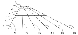
- FIG. 4 is a schematic diagram showing the calibration grid 40 stored in the storage unit 32.
- FIG. 5 shows an example when the calibration grid 40 is captured by the camera 10 and superimposed on the horizontally inverted image P1. It is a schematic diagram shown.
- the storage unit 32 stores a calibration grid 40 shown in FIG.
- This lattice 40 is the position and real space on the image P1 of each part on the road surface of the road 400 shown in the image P1 in a reference state assuming that the road 400 on which the vehicle 200 is traveling is a straight line. It is an example of the table (map) showing the correspondence with the position along the road 400 in FIG.
- the lines M1, M2, M3, M4, M5, M6, and M7 extending in the lateral direction of the grid 40 are equidistant intervals in the front-rear direction of the host vehicle 200 in the real space (for example, 10 [m] intervals in the real space) )
- the lines N1, N2, N3, N4, N5, and N6 extending in the vertical direction are equidistant intervals in the vehicle width direction of the host vehicle 200 in the real space (for example, 1 [m] intervals in the real space) It corresponds to. That is, the lattice 40 corresponds to a rectangular area in the front-rear direction 60 [m] and the vehicle width direction 5 [m] of the host vehicle 200 in the real space.
- the correction unit 33 corrects the lattice 40 stored in the storage unit 32 based on the curve state of the road 400 detected by the road state detection unit 31. Specifically, for example, when the road state detection unit 31 detects that the road 400 is in a straight line that is not curved, the correction unit 33 uses the lattice 40 in the reference state stored in the storage unit 32. Without being corrected, as shown in FIG. 5, it is directly superimposed on the image P1.
- the correction unit 33 corrects the lattice 40 in the reference state so as to follow the detected curve of the road 400. I do.
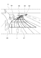
- FIG. 6 schematically illustrates a state in which the host vehicle 200 is traveling on the left lane L1 of a horizontal road that is gently curved in the right direction of, for example, three lanes on one side, from the viewpoint from above.
- FIGS. 7 and 7 are examples of an image P1 obtained by reversing the image P0 captured by the camera 10 shown in FIG. 6, and FIG. 8 is corrected so as to follow the curve of the road 400 shown in FIGS.
- FIG. 7 is a diagram showing a state in which a grid 40 ′ is superimposed on the image P1 shown in FIG. 6.
- FIG. 9 shows that the own vehicle 200 exits a side road lane L1 branched from the two-lane highway on the left side, for example, and curves to the right of the side lane L1.
- FIG. 10 is a diagram schematically illustrating the state of the camera 10 from above
- FIG. 10 is an example of an image P1 obtained by horizontally inverting the image P0 captured by the camera 10 illustrated in FIG. 9,
- FIG. 10 is a diagram showing a state in which a lattice 40 ′ corrected to follow the curve of the road 400 shown is superimposed on the image P ⁇ b> 1 shown in FIG. 9.
- the correction unit 33 sets the grid 40 to be superimposed on the image P1 in FIG. Then, it is transformed into a lattice 40 ′ along the detected curve of the road 400 and superimposed on the image P 1 of FIG. 6 as shown in FIG. Thereby, it is possible to specify the positional relationship between each part on the road surface of the road 400 and the target object in contact with the road surface with the host vehicle 200 along the curve of the road 400 in the real space.
- the correction unit 33 displays the image P1 in FIG.
- the grid 40 to be superimposed is transformed into a grid 40 ′ along the detected curve of the road 400 and superimposed on the image P 1 of FIG. 9 as shown in FIG.
- the positional relationship between each part on the road surface of the road 400 and the vehicle 200 along the curve of the road 400 in the real space can be specified.
- the object recognizing unit 34 follows vehicles 301, 302,... (Hereinafter referred to as succeeding vehicles 301) running behind the host vehicle 200 in the image P ⁇ b> 1. To detect.
- the object recognizing unit 34 stores in advance a pattern such as a contour shape or a pattern mainly on the front surface of a vehicle including a motorcycle or the like in the storage unit 32, and the stored pattern is subjected to pattern matching or the like with respect to the image P1.
- the subsequent vehicle 301 is detected.
- the object recognition unit 34 detects the position of the subsequent vehicle 301 or the like in the image P1 by detecting the position of the detected subsequent vehicle 301 or the like on the road surface.
- the traveling lane detection unit 35 creates a road 400 in the real space based on the grid 40 obtained by correcting the position of the succeeding vehicle 301 or the like recognized by the object recognition unit 34 on the image P1 by the correction unit 33.
- the position along the road 400 in the real space is specified by converting to the position along the road, and the lane in which the succeeding vehicle 301 or the like is traveling in the real space is specified.
- the lattice 40 in a straight line where the road 400 is not curved, the lattice 40 remains the lattice 40 in the reference state, and the lattice 40 in the reference state is superimposed on FIG. Accordingly, the lane is specified in the real space of each succeeding vehicle 301 or the like.
- the traveling lane detector 35, the following vehicle 301 travels in the same lane L ⁇ b> 1 as the own vehicle 200, and the following vehicle 302 is adjacent to the right of the traveling lane L ⁇ b> 1 of the own vehicle 200 ( It is determined that the vehicle travels in the adjacent lane (L2) and the following vehicle 303 is traveling in the lane (adjacent lane) L3 adjacent to the right of the adjacent lane L2.
- the traveling lane detection unit 35 follows each of the following vehicles 301 according to the state where the deformed lattice 40 ′ is superimposed. Identify the lane in real space such as.
- the traveling lane detection unit 35 causes the subsequent vehicle 302 to travel in the lane (adjacent lane) L2 adjacent to the right of the traveling lane L1 of the host vehicle 200, and the subsequent vehicles 303, 304, 305. Specifies that the vehicle is traveling in a lane (adjacent lane) L3 adjacent to the right of the adjacent lane L2.
- the traveling lane detector 35 detects each succeeding vehicle according to the state in which the deformed lattice 40 ′ is superimposed.
- a lane is specified in a real space such as 301.
- the traveling lane detector 35 specifies that the following vehicles 301 and 306 are traveling in the same lane L1 as the host vehicle 200, as shown in FIG.
- the distance calculation unit 36 obtains the distance along the curve of the road 400 between the position of the own vehicle 200 and the position of the succeeding vehicle 301 in the real space based on the grid 40 obtained by the correction by the correction unit 33. .
- the notification output unit 37 includes a lane L2 adjacent to the lane L1 in which the vehicle 200 is traveling, and the distance calculation unit in which the lane in which the subsequent vehicle 301 detected by the travel lane detection unit 35 is traveling.
- the distance calculated by 36 is shortened in time series, that is, when a subsequent vehicle traveling in the adjacent lane L2 is approaching the host vehicle 200, a signal for notifying the approach of the subsequent vehicle is monitored. Output to 90.
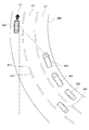
- the monitor 90 visually displays an image P1 obtained by horizontally inverting the image P0 taken by the camera 10 by the camera ECU 30. At this time, when the camera ECU 30 outputs a signal that informs the adjacent lane L2 of the following vehicle having a higher traveling speed than the own vehicle 200 so as to approach the own vehicle 200, the monitor 90 displays, for example, FIG. As shown in FIG. 3, a vehicle detection frame 350 surrounding the detected subsequent vehicle 302 is superimposed on the image P1.
- the camera 10 installed on the right side of the host vehicle 200 captures a right rear area of the host vehicle 200 at a predetermined cycle, and the captured image is input to the camera ECU 30.
- the camera ECU 30 converts each image periodically input from the camera 10 into a left-right inverted image P1.
- the road state detection unit 31 detects the state of the curve of the road 400 on which the host vehicle 200 is traveling based on a plurality of images P1 that are periodically input to the camera ECU 30 and reversed left and right. The detection of the state of the curve is based on each image P1 taken at different timings in time series when the end point 411 of the specific white line 410 shown in FIG. 2 moves backward as the host vehicle 200 travels. It is determined by the position transition above.
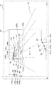
- FIG. 12 schematically shows how the end point 411 moves from the initial position R1 to the position R2 ′, the position R3 ′, the position R4 ′, and the position R5 ′ in the image P1 as the host vehicle 200 travels. It is a thing.
- the road condition detection unit 31 detects the positions R1, R2 ′, R3 ′, R4 ′, R5 ′ of the end points 411 that move with time on the image P1, for example, as the positions of the XY orthogonal coordinates in FIG.
- the position R1, the position R2, the position R3, the position R4, and the position R5 are vehicle speeds (CAN20 at that time) of the host vehicle 200 with a steering angle of 0 [degree] in a reference state where the road 400 is not curved.
- the predicted positions R1, R2, R3, R4, and R5 are based on a steering angle of 0 [degree] using the vehicle speed of the host vehicle 200 input from the in-vehicle network 20.
- the predicted positions R1, R2, R3, R4, and R5 in this reference state are aligned on a straight line.
- the positions R1, R2 ′, R3 ′, R4 ′, and R5 ′ detected by the road condition detection unit 31 are not aligned, and the position R2 ′ is shifted from the position R2 in the X-axis direction and the Y-axis direction, respectively.
- the subsequent positions R3 ′, R4 ′, and R5 ′ are also shifted in the X-axis direction and the Y-axis direction from the corresponding positions R3, R4, and R5, respectively.
- This positional deviation in the X-axis direction and the Y-axis direction indicates that the direction of the host vehicle 200 is changing in time series, that is, the road 400 on which the host vehicle 200 is traveling is curved. Yes.
- the correction unit 33 corrects the calibration grid 40 based on the curve state of the road 400 detected by the road state detection unit 31.
- a deviation amount ⁇ R2x in which the position R2 ′ detected by the road state detection unit 31 is displaced in the X-axis direction from the predicted position R2 in the reference state (beside the X-axis in FIG. 12).
- the following description is the same.
- the amount of displacement ⁇ R2y displaced in the Y-axis direction (described beside the Y-axis in FIG. 12; the same applies hereinafter), and the position R3 ′ from the predicted position R3 in the reference state
- the deviations ⁇ R3x and ⁇ R3y and R4 ′ which are displaced in the X-axis direction and the Y-axis direction are shifted from the predicted position R4 in the reference state in the X-axis direction.
- the amount ⁇ R4x and the amount of displacement ⁇ R4y, R5 ′ that is displaced in the Y-axis direction are displaced in the Y-axis direction from the amount of displacement ⁇ R5x that is displaced in the X-axis direction from the predicted position R5 in the reference state. Based on the deviation amount ⁇ R5y, the lattice 40 shown in FIG. 2 is deformed.
- the movement destination positions other than the positions R2, R3, R4, and R5 in the lattice 40 are the movement destination positions R2 ′, R3 ′, and R4 ′ of these positions R2, R3, R4, and R5.
- R5 ′ can be calculated as representative points, whereby the lattice 40 can be deformed along the curved road 400.
- the correction amount for deformation of the grid 40 is calculated.
- the calculation may be performed only for a partial region P2 behind the host vehicle 200 shown in FIG. Thereby, the calculation amount for correction
- suppression of calculation load is one of the important issues.
- the target recognition unit 34 detects the following vehicle from the image P1.
- the traveling lane detector 35 identifies the lane in which the subsequent vehicle is traveling based on the corrected grid 40 '.
- the distance calculation unit 36 obtains the distance along the curve of the road 400 from the own vehicle 200 to the following vehicle detected in the image P1 based on the corrected grid 40 ′.
- the camera ECU 30 identifies the detected lane in which each subsequent vehicle travels and the distance along the curve of the road 400 from the own vehicle 200 to each subsequent vehicle. And the alerting
- the notification output unit 37 detects a succeeding vehicle traveling in the adjacent lane L2 approaching the host vehicle 200, the monitor 90 A notification signal is output.
- the monitor 90 displays a vehicle detection frame 350 that surrounds the succeeding vehicle 302 as shown in FIG. It is displayed superimposed on the image P1.
- the notification output unit 37 follows the following vehicle that travels in the lane L1 in which the host vehicle 200 travels and the succeeding vehicle that travels in the adjacent lane L3. Even if the vehicle approaches the vehicle 200, no notification signal is output. Similarly, even if the following vehicle travels in the adjacent lane L2, the notification output unit 37 does not output a notification signal even when the subsequent vehicle is not approaching the host vehicle 200.
- the monitor 90 Since there is no notification signal output from the notification output unit 37, the monitor 90 displays the image P1 without adding a vehicle detection frame 350 that alerts the driver to any subsequent vehicle.
- the camera ECU 30 and the electronic mirror system 1 of the present embodiment based on the image P1 of the camera 10 provided in the host vehicle 200, the following vehicle 301 or the like shown in the image P1 of the camera 10, The positional relationship with the own vehicle 200 along the road 400 in the real space can be accurately obtained.
- this embodiment demonstrated only the positional relationship of the own vehicle 200 and the following vehicle mainly on the right rear of the own vehicle 200 image
- the own vehicle The positional relationship between the own vehicle 200 and the following vehicle, mainly the rear left side of the own vehicle 200, taken by the camera 10 provided on the left side of the own vehicle 200 is similarly implemented.
- this embodiment demonstrated only the positional relationship of the following vehicle and the own vehicle 200 which exist behind the own vehicle 200
- the calibration apparatus and electronic mirror system which concern on this invention are not only a subsequent vehicle.
- the positional relationship between the preceding vehicle existing ahead of the host vehicle 200 and the host vehicle 200 can be similarly applied. In this case, the camera which faces the front of the own vehicle is applied.
- the grid 40 is deformed in accordance with the degree of bending of the road 400, and the position of the succeeding vehicle in the image P1 is obtained by the lane and the distance along the lane represented by the deformed grid 40 ′.
- the image P1 is converted into an image of another coordinate system specified by the horizontal lines M1, M2,... And the vertical lines N1, N2,.
- the position (lane, distance from own vehicle 200, etc.) of the following vehicle may be specified on the image of another coordinate system obtained as described above.
Landscapes
- Engineering & Computer Science (AREA)
- Physics & Mathematics (AREA)
- General Physics & Mathematics (AREA)
- Theoretical Computer Science (AREA)
- Computer Hardware Design (AREA)
- Signal Processing (AREA)
- Multimedia (AREA)
- Mechanical Engineering (AREA)
- Computer Vision & Pattern Recognition (AREA)
- Traffic Control Systems (AREA)
- Image Analysis (AREA)
- Fittings On The Vehicle Exterior For Carrying Loads, And Devices For Holding Or Mounting Articles (AREA)
- Closed-Circuit Television Systems (AREA)
- Controls And Circuits For Display Device (AREA)
- Image Processing (AREA)
Applications Claiming Priority (2)
| Application Number | Priority Date | Filing Date | Title |
|---|---|---|---|
| JP2018-109139 | 2018-06-07 | ||
| JP2018109139A JP7226930B2 (ja) | 2018-06-07 | 2018-06-07 | キャリブレーション装置及び電子ミラーシステム |
Publications (1)
| Publication Number | Publication Date |
|---|---|
| WO2019235004A1 true WO2019235004A1 (ja) | 2019-12-12 |
Family
ID=68770232
Family Applications (1)
| Application Number | Title | Priority Date | Filing Date |
|---|---|---|---|
| PCT/JP2019/008266 Ceased WO2019235004A1 (ja) | 2018-06-07 | 2019-03-04 | キャリブレーション装置及び電子ミラーシステム |
Country Status (2)
| Country | Link |
|---|---|
| JP (1) | JP7226930B2 (https=) |
| WO (1) | WO2019235004A1 (https=) |
Cited By (1)
| Publication number | Priority date | Publication date | Assignee | Title |
|---|---|---|---|---|
| CN113911035A (zh) * | 2021-11-08 | 2022-01-11 | 广州优创电子有限公司 | 一种智能后视镜及智能后视镜控制方法 |
Families Citing this family (1)
| Publication number | Priority date | Publication date | Assignee | Title |
|---|---|---|---|---|
| JP7304334B2 (ja) | 2020-12-03 | 2023-07-06 | 本田技研工業株式会社 | 車両制御装置、車両制御方法、およびプログラム |
Citations (4)
| Publication number | Priority date | Publication date | Assignee | Title |
|---|---|---|---|---|
| JPH07223487A (ja) * | 1994-02-14 | 1995-08-22 | Mitsubishi Motors Corp | 車両用周囲状況表示装置 |
| JP2007164636A (ja) * | 2005-12-15 | 2007-06-28 | Toyota Motor Corp | 道路区画線検出装置 |
| WO2012147187A1 (ja) * | 2011-04-27 | 2012-11-01 | トヨタ自動車株式会社 | 周辺車両検出装置 |
| JP2015028696A (ja) * | 2013-07-30 | 2015-02-12 | アルパイン株式会社 | 車両後側方警報装置、車両後側方警報方法および他車両距離検出装置 |
Family Cites Families (1)
| Publication number | Priority date | Publication date | Assignee | Title |
|---|---|---|---|---|
| JP4638369B2 (ja) | 2006-03-28 | 2011-02-23 | 富士重工業株式会社 | 車線位置検出装置 |
-
2018
- 2018-06-07 JP JP2018109139A patent/JP7226930B2/ja active Active
-
2019
- 2019-03-04 WO PCT/JP2019/008266 patent/WO2019235004A1/ja not_active Ceased
Patent Citations (4)
| Publication number | Priority date | Publication date | Assignee | Title |
|---|---|---|---|---|
| JPH07223487A (ja) * | 1994-02-14 | 1995-08-22 | Mitsubishi Motors Corp | 車両用周囲状況表示装置 |
| JP2007164636A (ja) * | 2005-12-15 | 2007-06-28 | Toyota Motor Corp | 道路区画線検出装置 |
| WO2012147187A1 (ja) * | 2011-04-27 | 2012-11-01 | トヨタ自動車株式会社 | 周辺車両検出装置 |
| JP2015028696A (ja) * | 2013-07-30 | 2015-02-12 | アルパイン株式会社 | 車両後側方警報装置、車両後側方警報方法および他車両距離検出装置 |
Cited By (2)
| Publication number | Priority date | Publication date | Assignee | Title |
|---|---|---|---|---|
| CN113911035A (zh) * | 2021-11-08 | 2022-01-11 | 广州优创电子有限公司 | 一种智能后视镜及智能后视镜控制方法 |
| CN113911035B (zh) * | 2021-11-08 | 2023-08-25 | 广州优创电子有限公司 | 一种智能后视镜及智能后视镜控制方法 |
Also Published As
| Publication number | Publication date |
|---|---|
| JP2019213108A (ja) | 2019-12-12 |
| JP7226930B2 (ja) | 2023-02-21 |
Similar Documents
| Publication | Publication Date | Title |
|---|---|---|
| JP5172314B2 (ja) | ステレオカメラ装置 | |
| US11210533B1 (en) | Method of predicting trajectory of vehicle | |
| CN110232836A (zh) | 物体识别装置以及车辆行驶控制系统 | |
| US20140043466A1 (en) | Environment image display apparatus for transport machine | |
| US10099617B2 (en) | Driving assistance device and driving assistance method | |
| CN111034186B (zh) | 周围车辆显示方法及周围车辆显示装置 | |
| TWI533694B (zh) | 車用障礙物偵測顯示系統 | |
| JP6778620B2 (ja) | 区画線検出装置、区画線検出システム、及び区画線検出方法 | |
| WO2016129552A1 (ja) | カメラパラメータ調整装置 | |
| US10266114B2 (en) | Image generating device and image generating method | |
| WO2015129280A1 (ja) | 画像処理装置および画像処理方法 | |
| CN103381825B (zh) | 使用多个照相机的全速车道感测 | |
| WO2019235004A1 (ja) | キャリブレーション装置及び電子ミラーシステム | |
| JP6439233B2 (ja) | 車両用画像表示装置及び画像処理方法 | |
| JP6032141B2 (ja) | 走行路面標示検知装置および走行路面標示検知方法 | |
| JP7746925B2 (ja) | 表示制御装置、表示装置、表示システム、車両、表示制御方法及びプログラム | |
| JP6489645B2 (ja) | 画像処理装置 | |
| US20250206137A1 (en) | Vehicle surrounding environment display device, and method for controlling vehicle surrounding environment display device | |
| JP5831331B2 (ja) | 車両の後側方撮影装置 | |
| US12083959B2 (en) | Image control system | |
| JP2012178639A (ja) | 画像処理装置、駐車制御システム、及び、画像処理方法 | |
| US20230242137A1 (en) | Notification device and notification method | |
| JP6586972B2 (ja) | 車両用画像表示装置及び画像処理方法 | |
| JP7740139B2 (ja) | 表示制御装置、表示装置、表示システム、車両、表示制御方法及びプログラム | |
| US12125295B2 (en) | Road surface marking detection device, notification system provided with the same, and road surface marking detection method |
Legal Events
| Date | Code | Title | Description |
|---|---|---|---|
| 121 | Ep: the epo has been informed by wipo that ep was designated in this application |
Ref document number: 19815915 Country of ref document: EP Kind code of ref document: A1 |
|
| NENP | Non-entry into the national phase |
Ref country code: DE |
|
| 122 | Ep: pct application non-entry in european phase |
Ref document number: 19815915 Country of ref document: EP Kind code of ref document: A1 |