WO2019227147A1 - Mine planning method and system - Google Patents
Mine planning method and system Download PDFInfo
- Publication number
- WO2019227147A1 WO2019227147A1 PCT/AU2019/050529 AU2019050529W WO2019227147A1 WO 2019227147 A1 WO2019227147 A1 WO 2019227147A1 AU 2019050529 W AU2019050529 W AU 2019050529W WO 2019227147 A1 WO2019227147 A1 WO 2019227147A1
- Authority
- WO
- WIPO (PCT)
- Prior art keywords
- pushback
- mine
- model
- design
- ramp
- Prior art date
- Legal status (The legal status is an assumption and is not a legal conclusion. Google has not performed a legal analysis and makes no representation as to the accuracy of the status listed.)
- Ceased
Links
Classifications
-
- G—PHYSICS
- G01—MEASURING; TESTING
- G01V—GEOPHYSICS; GRAVITATIONAL MEASUREMENTS; DETECTING MASSES OR OBJECTS; TAGS
- G01V20/00—Geomodelling in general
-
- G—PHYSICS
- G06—COMPUTING OR CALCULATING; COUNTING
- G06Q—INFORMATION AND COMMUNICATION TECHNOLOGY [ICT] SPECIALLY ADAPTED FOR ADMINISTRATIVE, COMMERCIAL, FINANCIAL, MANAGERIAL OR SUPERVISORY PURPOSES; SYSTEMS OR METHODS SPECIALLY ADAPTED FOR ADMINISTRATIVE, COMMERCIAL, FINANCIAL, MANAGERIAL OR SUPERVISORY PURPOSES, NOT OTHERWISE PROVIDED FOR
- G06Q50/00—Information and communication technology [ICT] specially adapted for implementation of business processes of specific business sectors, e.g. utilities or tourism
- G06Q50/02—Agriculture; Fishing; Forestry; Mining
-
- E—FIXED CONSTRUCTIONS
- E21—EARTH OR ROCK DRILLING; MINING
- E21C—MINING OR QUARRYING
- E21C41/00—Methods of underground or surface mining; Layouts therefor
-
- E—FIXED CONSTRUCTIONS
- E21—EARTH OR ROCK DRILLING; MINING
- E21C—MINING OR QUARRYING
- E21C41/00—Methods of underground or surface mining; Layouts therefor
- E21C41/16—Methods of underground mining; Layouts therefor
-
- E—FIXED CONSTRUCTIONS
- E21—EARTH OR ROCK DRILLING; MINING
- E21C—MINING OR QUARRYING
- E21C41/00—Methods of underground or surface mining; Layouts therefor
- E21C41/26—Methods of surface mining; Layouts therefor
-
- G—PHYSICS
- G06—COMPUTING OR CALCULATING; COUNTING
- G06F—ELECTRIC DIGITAL DATA PROCESSING
- G06F30/00—Computer-aided design [CAD]
- G06F30/20—Design optimisation, verification or simulation
-
- G—PHYSICS
- G06—COMPUTING OR CALCULATING; COUNTING
- G06Q—INFORMATION AND COMMUNICATION TECHNOLOGY [ICT] SPECIALLY ADAPTED FOR ADMINISTRATIVE, COMMERCIAL, FINANCIAL, MANAGERIAL OR SUPERVISORY PURPOSES; SYSTEMS OR METHODS SPECIALLY ADAPTED FOR ADMINISTRATIVE, COMMERCIAL, FINANCIAL, MANAGERIAL OR SUPERVISORY PURPOSES, NOT OTHERWISE PROVIDED FOR
- G06Q10/00—Administration; Management
- G06Q10/06—Resources, workflows, human or project management; Enterprise or organisation planning; Enterprise or organisation modelling
- G06Q10/063—Operations research, analysis or management
- G06Q10/0631—Resource planning, allocation, distributing or scheduling for enterprises or organisations
-
- G—PHYSICS
- G06—COMPUTING OR CALCULATING; COUNTING
- G06Q—INFORMATION AND COMMUNICATION TECHNOLOGY [ICT] SPECIALLY ADAPTED FOR ADMINISTRATIVE, COMMERCIAL, FINANCIAL, MANAGERIAL OR SUPERVISORY PURPOSES; SYSTEMS OR METHODS SPECIALLY ADAPTED FOR ADMINISTRATIVE, COMMERCIAL, FINANCIAL, MANAGERIAL OR SUPERVISORY PURPOSES, NOT OTHERWISE PROVIDED FOR
- G06Q10/00—Administration; Management
- G06Q10/06—Resources, workflows, human or project management; Enterprise or organisation planning; Enterprise or organisation modelling
- G06Q10/063—Operations research, analysis or management
- G06Q10/0633—Workflow analysis
-
- G—PHYSICS
- G06—COMPUTING OR CALCULATING; COUNTING
- G06F—ELECTRIC DIGITAL DATA PROCESSING
- G06F2111/00—Details relating to CAD techniques
- G06F2111/04—Constraint-based CAD
-
- G—PHYSICS
- G06—COMPUTING OR CALCULATING; COUNTING
- G06F—ELECTRIC DIGITAL DATA PROCESSING
- G06F2111/00—Details relating to CAD techniques
- G06F2111/10—Numerical modelling
Definitions
- the field of the invention is methods and systems for mining design and planning.
- Applications of the invention are in designing for extraction plans, pushbacks and/or ramps and scheduling.
- Mining is the process of extracting valuable material from the earth.
- Materials extracted from mines include some of the modern world’s most important commodities: for example, coal, copper, diamonds, iron, gold, silver, molybdenum, and uranium.
- mine planners evaluate the mining method, estimate the production capacity and produce detailed exploitation plans.
- Mine planning and design aim to plan extraction of material from the mine with the objectives of maximizing yield, minimizing operational costs and compliance with regulatory and safety requirements.
- Ore deposits are extracted using a variety of mining methods.
- quarries and open pit are the most common, while block, panel, sub-level caving and sub-level stopping are usually selected as mining methods in underground mines.
- the choice of mining method must consider internal and external factors. Natural conditions, investment capability of companies, public policies of the region and the state of art technology should be taken into consideration to evaluate different methods.
- the spatial location and quality of the geological resources, the rock strength, and the topography are the most relevant aspects to be considered.
- a typical input to the mine planning is a geological model; in this model geological resources are represented as a block model, a regular-spaced grid of blocks.
- a 3D block is typically a prismatic shape that is represented by the coordinates of its centroid (x,y,z).
- This model contains the main information for the planning stage. For instance, rock alteration, mineralisation zones, rock densities and element concentration are fundamental in defining the value of the mine. Mine planners, with the help of other professional disciplines, are responsible for transforming geological resources to ore reserves.
- the Ultimate Pit Limit (UPL) defines the mineable volume of material that generates profits.
- the size and shape of the pit mostly depends on geotechnical, processing and economic factors. Smaller inner pits are known as intermediate pits. The most common technique used to define the inner pits
- Pushbacks, phases or mining cuts, are sub-volumes inside the UPL. These volumes must be logically designed, allowing safe operation of the mining equipment (loaders, wheel-dozers, hauling trucks).
- the main components of the pushbacks are ramps and benches.
- a bench can be defined as the set of blocks that shares a level inside of a pushback.
- the pushback should be fully connected by a ramp, and every bench of each pushback must have a minimum width defined by the equipment selected. Therefore, the size and amount of equipment need to be taken into account when pushbacks are designed.
- the ore tonnage inside pushbacks must be enough to sustain the plant capacity over a period, where typically 1 - 3 years time is taken.
- Nested pits are used as guidelines to design pushbacks.
- a 'Pushback' represents a region that can be mined in a single continuous operation as defined within the Ultimate Pit.
- the basic objective is to create a pushback shape which attempts to meet defined primary targets, such as ore tonnage, stripping ratios or mined grade.
- primary targets such as ore tonnage, stripping ratios or mined grade.
- nested pits cannot guarantee a minimum mining width. Therefore, the pushback design requires considerable intervention by mining engineers.
- pushbacks represent phases in open-cut mining, i.e. a series of pits satisfying production requirements and operational constraints for the mining operation.
- a pit is developed over a period of anywhere from 2 to 30 or 40 years, depending on the size and depth of the deposit.
- Pushbacks are then a sequence of nested pits each representing around 2 years of production. For operational and geotechnical reasons, designing these pushbacks is a crucial part of mine planning lf the life of the mine is more than 3-4 years, then pushbacks are required. The majority of open cut mines are of this type.
- the LG approach is to (artificially) increase the cost of production, so that smaller and smaller pits are the outcome of their algorithm. This gives a formal way of producing nested pits - an inflated cost of production shrinks the pit in size. However, these nested pits suffer from a number of drawbacks.
- the pits may be too narrow in parts, hence operationally infeasible for mining equipment access
- the pits may be disconnected, which makes for very inefficient designs, due to the problem of equipment access via ramps.
- each pit should represent about two years of production.
- the current practice is that the output of the LG algorithm is used by mine planners as a starting point to produce a practical pushback design, satisfying all production and access requirements. Ramps are required to be added to the design at this stage.
- Ramps are roads that allow access to the working places. Their maximum slope is constrained by the haulage equipment.
- the aim of the ramp design is to minimise the construction and operational cost, which includes minimising the hauling distance and traffic congestion.
- the road design should be included as early as possible because there is a significant difference between a pushback design with and without ramps.
- engineers need to take into account strategic factors. Pit exit locations, pit geometry, the evolution of the pit shape and the influence of the topography are crucial to minimise the haulage cost. Roads can change the overall shape of the pit dramatically.
- a computer implemented method of mine design comprising obtaining a three dimensional (3D) model for a mine, the 3D model characterizing physical material of the mine as a plurality of geometric elements, each geometric element representing a portion of the physical material extractable from the mine, applying a mathematical model, based on mathematical modelling of behavior of connected bubbles, to cluster geometric elements from the 3D model based on physical location and properties of the physical material for each of the geometric elements, and selecting at least one set of a plurality of contiguous geometric elements for extraction based on the clustering.
- Each set of a plurality of contiguous blocks can be associated with a phase of a mining process.
- the mathematical model can include mathematical constraints reflecting operational constraints for the mine type.
- the bubble model can be used for pushback design and operational constraints include connectivity, minimum bench width and appropriate angles between pushbacks.
- operational constraints include connectivity, minimum bench width and appropriate angles between pushbacks.
- the mathematical model balances selection of contiguous geometric elements to minimise geometric surface area while maximizing economic value for each pushback.
- the mathematical model includes a geometric compactness tradeoff factor to enable an operator controllable weighting between maximizing economic value and pushback geometry to be defined and input to the mathematical model.
- the mathematical model comprises:
- Some embodiments of the method further comprise the steps of adjusting the compactness factor and producing a further pushback design.
- the compactness factor can also be adjusted to produce further excavation plans ln some embodiments the compactness factor is adjusted incrementally to produce a plurality of pushback designs or excavation plans.
- a method of designing ramps for a set of pushbacks based on a linear programming formulation to find a minimum cost ramp with vertical and horizontal alignment constraints for a given pit and a given ramp width taking into account stripping associated with ramp excavation, by applying a geological model which is assumed to be represented as a regularly spaced set of blocks including the topography of the pit, and ramp width equivalent to the block size in x or y and the dimension in z represents the maximum ramp slope
- a computer implemented mine planning method comprising the steps of:
- the mathematical model is based on mathematical modelling of behavior of connected bubbles, and for each pushback the mathematical model balances selection of contiguous blocks to minimise geometric surface area while maximizing economic value for each pushback.
- the mathematical model includes a geometric compactness tradeoff factor to enable an operator controllable weighting between maximizing economic value and pushback geometry to be defined and input to the mathematical model.
- Some embodiments of the method include further comprising the steps of adjusting the compactness factor and producing a further pushback design ln some embodiments the compactness factor is adjusted incrementally to produce a plurality of pushback designs and further comprising the step of outputting one or more of the plurality of pushback designs.
- Some embodiments of the method further comprise the step of performing ramp design for one or more pushback designs.
- the ramp design is performed in accordance with the method as described above.
- a mine planning system implemented using computer processing and memory resources, the system comprising at least one module configure to implement the methods as described above.
- Figure la is a flowchart illustrating the current mine planning process
- Figure lb is a flowchart showing the change of the mine planning process using an embodiment of the pushback design method the invention.
- Figure 2 illustrates the main outputs of stages of the open pit mine planning process.
- Figure 3 illustrates a flowchart of a bubble pit optimization process.
- Figure 4 illustrates bubble pit graphs showing effect of compactness factor.
- Figure 5 shows the variation of the NPV versus the compactness factor for a prototype test of the pushback design algorithm compared with an engineer prepared design using the same mine data.
- Figure 6 illustrates impact of compactness factor (before introducing unit
- Figure 7 illustrates an example of drawpoint sequencing (Mine sequence optimization for Block caving using concept of 'Best and worst case.
- Figure 8 illustrates a caving propagation slope
- FIGS 9a and 9b illustrate scheduled block removal times with two different compactness values.
- Figure 10 illustrates open pit ramps.
- Figure 11 is a block diagram of an embodiment of a system configured to implement the mine planning method.
- Figure 12 is a high level flowchart of the bubble model method.
- the disclosed methods can be used for designing pushbacks for open cut mines, or for planning caving or stoping for underground mining.
- the bubble model can include mathematical constraints reflecting operational constraints for the different mine types.
- FIG. 12 A high level example of the method is shown in Figure 12, the process starts by obtaining a three-dimensional (3D) model for a mine 1210, for example by retrieving from a database, system memory or storage media, the 3D model may also be input to the system, for example via email or file transfer.
- the 3D model characterizes physical material of the mine as a plurality of geometric elements, each geometric element representing a portion of the physical material extractable from the mine.
- Such models are often referred to as block models.
- a system processor appropriately programmed with a mathematical model based on modelling of connected bubbles, applies the mathematical model 1220 to cluster geometric elements from the three-dimensional (3D) model based on physical location and properties of the physical material for each of the geometric elements - this data being extracted from the 3D model.
- the processor selects at least one set of a plurality of contiguous geometric elements for extraction 1230.
- the properties of the physical material can include any data captured in the 3D model, including economic value for each element.
- the bubble model can include mathematical constraints reflecting the operational constraints of connectivity, minimum bench width and appropriate angles between pushbacks. This model is applied in conjunction with economic data for pushback design. For underground mining the bubble model can also be used.
- the present method enables mathematical model based mine planning, which simultaneously satisfy operational constraints and maximize NPV. This could be used by large mining companies with in-house design capability, mining consulting companies and mining software providers.
- Embodiments may also be utilised in scheduling aspects of mine planning, for example for planning temporal as well as physical aspects of extraction lt should be appreciated that planning includes extraction of both valuable target material (ore or“pay dirt” carrying the target minerals) and waste material, often referred to as“overburden”, which must be extracted to get to the valuable material.
- Other required infrastructure such as accessways, roads and or ramps also form part of a comprehensive mine plan and are encompassed within the scope of the present invention.
- An input to the mine planning method is a 3- dimensional model of the mine characterizing the target material as well as
- the 3D model characterizes physical material of the mine as a plurality of geometric elements, each geometric element representing a portion of the physical material extractable from the mine.
- the 3D model may be based on core samples and/or seismic data for the mine area. Such 3D models are often referred to as block models.
- a 3-dimensional volume is the input to the invention, where the volume is divided into geometrical elements, i.e. small pieces, often called blocks, but could be panels or other larger or irregular sub-regions.
- the composition of the geometrical elements is known and classified into valuable material, waste and contaminants. The problem is to decide which elements to extract and in what sequence. Constraints include equipment requirements, access, geotechnical stability and others.
- the aim of mine planning is to balance maximizing value extracted from the mine with the practical limitations and costs associated with the extraction ln principle, the aim is to extract the maximum volume of valuable material while minimizing total volume extracted.
- Embodiments of the disclosed methods apply to this optimisation problem; a mathematical model based on mathematical modelling of connected bubbles.
- the bubble clustering method consists of generating a cluster of elements such that the external surface area of the cluster is minimized; this is done to generate compact and most likely connected clusters.
- Our clustering method requires that the surface area of each element as well as the surface area of the combination of elements can be computed or estimated.
- the bubble cluster method is applied to a block model, a regular-spaced grid of blocks.
- a 3D block is typically a prismatic shape that is represented by the coordinates of its centroid (x,y,z) which contains the main information for the planning stage. Therefore, blocks are the basic unit (or elements) that can be part of the clusters lt is worth noting that the bubble cluster are not limited to block models, and the clustering method applies to any framework in which the area of the elements can be minimised.
- the bubble cluster model has several advantages when applied in the context of mine planning.
- Embodiments of the disclosed mine planning methods operate to minimise the boundary surface area of the set of elements chosen to be extracted in a given period of time or the set of elements that satisfies a given characteristic, as a key part of the optimisation process. Such a minimisation produces clusters of elements. There are several advantages of using the disclosed bubble model method for clustering of the chosen elements.
- lf a cluster of elements of a given volume minimises boundary surface area, then the cluster behaves mathematically like a bubble and so will be similar to a round sphere enclosing a given volume.
- the restriction on size of the cluster corresponds to a mining constraint such as the volume required to be extracted in a given time period.
- This bubble behavior gives the clusters geometrical shapes with desirable properties, for example, when designing pushbacks or cutbacks, which are a series of nested pits forming an open pit mine. Each such nested pit represents a fixed amount of volume for production, typically around 2-4 years of feed to the processing plant.
- bubble clusters can also produce schedules for efficient extraction. Optimisation then gives a bonus for choosing elements with similar characteristics in a given time period and either a bonus for maximal overlap between the surface areas of the chosen elements or a penalty for the total surface area of the cluster of elements chosen.
- Bubble clusters will tend to reduce stress as the clusters will not have 'sharp corners’ where stress concentrates. This property can be used to optimise the extraction sequence of caving mines as well as defining the mining boundary and sequence of selective mining methods such as stoping mines or any other method that might be beneficiated by using bubble like clusters.
- Dump management and stockpiling sequencing consist of moving material from the mine to external facilities (or internal in the case of backfilling) permanently or temporarily. Similarly to the mining process, the dumping and re-handling operations require connected and wide areas to ensure the safe operation of the equipment.
- the bubble model can also be applied in this context.
- the following model is based on the bubble principle which is to minimise the surface area for a given volume in a non-homogeneous distribution field.
- This problem can be formulated as a linear model as follows.
- Open pit pushbacks are“clusters” of blocks that are: 1) connected, 2) satisfy minimum mining width (due to the mining equipment required for the extraction process), 3) the horizontal angle formed by the intersection of two pushbacks is not too small.
- Each pushback may have to contain a given amount of different materials such as ore, contaminants, waste.
- the total volume within the pushbacks is typically between 2-4 years of production ln most cases, traditional methods to define pushbacks (like the Lerchs and Grossman parametrization method) gives impractical pushbacks, i.e. do not satisfy all (or even any) of the three conditions already mentioned.
- the Bubble cluster method can be used to model the shape constraints of the pushback problem.
- the following formulation shows a simplified example of the pushback problem, in which the minimisation of the surface area of the bubble clusters corresponds to the second term of the objective function.
- a key feature of the disclosed method is to use a proxy, in the form of a mathematical model based on the behavior of soap bubbles, for the operational constraints of connectivity, minimum bench width and appropriate angles between pushbacks.
- each pushback should be a connected region, i.e. not have separated parts.
- the bench width is set by the requirements of mining equipment for ore production. Narrow angles between pushbacks give regions which are hard to access - having a sufficiently large angle eliminates this problem.
- a sequence of pushbacks is modeled as a cluster of soap bubbles. Surface tension of soap bubbles drives them to have the smallest area enclosing a given volume ln the context of mining, the bubble model defines the geometry of a pushback for mining the maximum value material with a minimal geometric surface area.
- soap bubbles have smallest area enclosing a given volume, such a volume will be associated with a single soap bubble in a cluster. For otherwise one can slide two pieces of bubbles enclosing parts of a given volume together to merge to form a larger bubble, enclosing the same volume but with less area. Further, since soap bubbles have constant mean curvature (this is a measure of 'bending' of the soap bubble surface) and form shapes like spheres, the minimal bench width property applies, hence giving large bench width.
- the practical application of the mathematical model in a mine planning algorithm incorporates a compactness factor, which can be a variable adjusted by the mine planner.
- the compactness factor is a measure of the dispersion of the blocks that compose the pushback. Or considered another way, it is a mechanism to mathematically enable relaxation of the bubble model geometry from a spherical approximation based on economic aspects. This is explained further in the paragraphs below. ln the bubble model approach, there are two potentially competing objectives - maximizing NPV by taking high value blocks early and minimizing the area of the boundary surface of each pushback, while enclosing a given volume.
- the mathematical model of soap bubble geometry can address the physical objective of minimizing the boundary surface for mine pushbacks.
- a purely geometric bubble model approach does not take into consideration the varying economic value of the material to be mined.
- the mathematical model of a soap bubble needs to be altered to allow relaxing of the bubble geometry to take into consideration the objective to preferentially mine the more valuable regions and improve NPV.
- the objectives of maximizing NPV by taking high value blocks early and minimizing the area of the boundary surface of each pushback, while enclosing a given volume are combined by taking a weighted sum of the objectives.
- a percentage of the objective is maximizing NPV and the complementary percentage is for the objective of minimizing area lf we start with 0% contribution of minimizing area and 100% maximizing NPV, the result will be very similar to classical Lerchs Grossman nested pits, with capacity constraints of the bubble model having the only influence on the resulting pushback design.
- the geometric constraints of the bubble model are negated by the 100% weighting on NPV.
- the mine designer can adjust the degree of compactness (i.e. relative percentages of area and NPV) to achieve an appropriate design ln this process, the designer is able to understand the tradeoff between the operational constraints and the current methodology of nested pits, which optimises NPV but does not give practical designs ln particular, this means that for a given mine and ore body, the designer is able to experiment by running multiple designs with different compactness factors to see which one gives the largest NPV but still satisfies the required operational constraints.
- one disclosed method uses a unit transformation factor, denoted f, which transforms between area of a pushback and dollars of NPV. This enables a compactness factor varying between 0 and 100% to be used. ln another embodiment there is no unit transformation factor needed to compare units of area with units of dollars in NPV so the two terms can be combined. This is on a scale from around 0 to 1000 weighting of the area. Weighting of the area is used since the area is much smaller than the number of dollars in the units typically used. The weighting combines the NPV and area tradeoff into a single value which can be applied to all blocks.
- f unit transformation factor
- a unit transformation factor can be introduced to convert units of area to units of dollars, then the compactness factor can be thought of as a percentage, as discussed above, saying then we have a certain percent NPV and the complementary percent area.
- Figures la and lb show an example of current mine planning processes in Figure la compared with an alternative mine planning process using embodiments of the disclosed pushback planning method in Figure lb.
- Figure 2 illustrates the outputs of different phases of mine design process.
- Figure la represents the current typical planning procedure.
- This starts with the input data 102 including geological resource data (for example, a three-dimensional block model 210 produced from exploration which characterizes the type and location of the geological resources illustrated in Figure 2), precedence constraints and economical models.
- geological resource data for example, a three-dimensional block model 210 produced from exploration which characterizes the type and location of the geological resources illustrated in Figure 2
- precedence constraints for example, a three-dimensional block model 210 produced from exploration which characterizes the type and location of the geological resources illustrated in Figure 2
- This data is used to define the ultimate pit limit 108 and geometric ultimate pit shell 222 which defines the 3D boundary of the mine (i.e. shape of the cone) for extraction of the valuable material.
- This ultimate pit shell 108 is input to a process for designing nested pits 110 using conventional methods.
- Also input 112 to the nested pit design 110 are geological resource data (block model), precedence constraints, economical models, and revenue factors.
- the output from the nested pit design 110 is an initial design of pit shells 115, 225, which is input to a process for designing semi-practical pushbacks 120. Also input to the semi-practical pushback design process is geological resource data (including the block model 210), mining width constraints, and pushback target parameters (for example the tonnage for removal for each pushback).
- the output 122 from the semi practical pushback design is a set of semi-practical pushbacks 230 and pushback precedence (order) constraints.
- This semi-practical pushback design 122 is input to a scheduling planning process 125 along with scheduling parameters 128 to determine whether or not the design 122 is feasible 130 for practical implementation lf the design is not feasible 130 then the pushback design 120 and scheduling 125 processing is repeated until a feasible solution is found.
- the next step is to convert this to a practical pushback design 140 by adding ramps, based on ramp parameters (for example minimum width and turning angles based on equipment to be used and traffic) to provide a practical pushback design and precedence constraints 148.
- This is then input to a second scheduling process 150 using scheduling parameters 152 to produce a mine schedule 240 and dynamic cut-off policy 155.
- This is assessed for feasibility 160 and repeated 165, if necessary, and the design planning process ends 170 once a feasible design and schedule is found lt should be appreciated that the mine designing process is iterative and can be highly manual, taking significant time and resources to produce a feasible design. This entire process may also be repeated to generate multiple feasible plans which may be compared by a mine designer and a preferred one of these feasible designs chosen for implementation.
- Embodiments of the disclosed pushback design method can replace the steps of the design process for designing nested pits 110 and designing semi-practical pushbacks 122 (as shown in Figure la), with a single process 180 for designing semi-practical pushbacks 188 based on a bubble model (referred to as bubble pits) as shown in Figure lb.
- lnputs to the bubble pit process 180 include the ultimate pit shell 108, geological resource data (block model), precedence constraints, and economical models 182, similarly to nested pit designs.
- shape factor data mining width constraints and constraints based on 3D cone models
- pushback targets 185 are also input to the bubble pit processing.
- the output from the bubble pit modelling is a semi-practical pushback design and precedence constraints 188 which can be subject to scheduling 190 based on scheduling parameters 192 to assess the feasibility 194 of the design. And the process is repeated 195 if necessary to derive a feasible design or multiple feasible pushback designs for comparison.
- An embodiment also provides a ramp design method which may also be used with traditional pushback design methods.
- the pushback design method 180 provides a method to design pushbacks for open cut mines, which simultaneously satisfies operational constraints and maximizes NPV, the simultaneous satisfaction of these objectives is not known to be possible with any other mine planning method. Embodiments could be used by large mining companies with in- house design capability, mining consulting companies and mining software providers.
- Embodiments fit in the core of the open pit mine planning value chain and allow designers to both optimise and automate the pushback design stage.
- the disclosed method produces designs which can automatically satisfy connectivity and minimum mining width, and optimises NPV with these additional constraints.
- Embodiments also include a weighting factor which can be selected by a mine planner to adjust trade-offs between optimal NPV and operational constraints, allowing these to be fully explored.
- the inventor’s breakthrough is to use a physical model which forces the operational constraints indirectly but has the correct properties to achieve large scale optimisation, involving huge numbers of variables and constraints.
- characterization of the physical model is used to enable a computer implemented process to automatically or semi-automatically produce pushback designs. This can significantly decrease the time and manual effort associated with mine planning.
- the multi-objective function maximises the weighted value of the extracted blocks and minimises the area of the bubble pit, combined by a weighting given by the
- Constraint (6) ensures that the pits contain a given amount of attribute A. More than one attribute can be considered in a similar manner, and a tolerance can be added to the mass constraint by replacing the equality constraint with two inequality constraints.
- Constraints (7)-(9) identify which adjacent elements belong to the same pushback.
- Constraint (10) represents the vertical precedence (slope wall constraint).
- Constraint (11) ensures that the blocks can only belong to one pushback.
- Constraint (12) might represent other operational restrictions (e.g., block-level or bench-pushback scheduling, mining and processing bounds, variable cut-off grade, blending constraints, and/or the maximum number of pushback opened), and could involve bounds on x and y.
- V b V b .
- the process of transforming the block model to a valid set of bubble pits is illustrated in the flowchart of Figure 3.
- the inputs 310 to the process are:
- a first step 320 sets of parameters required for the bubble pit formulation are determined; these parameters include but are not limited to the target weight (tonnage) or volume for each pushback, and the compactness factor.
- a set of pushback instances are generated using the 3D mathematical bubble model, for example as defined in objective function 2.
- the set of pushbacks for the ultimate pit is generated by performing the bubble model optimisation for one pushback 340, removing the set of blocks comprising the pushback form the block model 350, and checking whether or not the block model is empty 355. lf the block model is not empty the optimisation function will be applied to select blocks for the next pushback. This process is repeated until the block model is empty - all blocks of the block model have been selected and assigned to a pushback lt should be appreciated that the output of the mathematical modelling is a plurality of data sets, one for each pushback with each set defining the blocks selected to comprise the pushback.
- the data sets defining each pushback can be transformed 360 to a block model format for display and input to further steps of the mine planning process.
- the transformation to a block model format may include a step of adding to the block characterisation, data for each block within the block model data defining the pushback for which the block has been selected. The steps of scheduling and feasibility assessment, and conversion of feasible designs to practical pushbacks can then proceed in accordance with standard
- the pushback design process can include the step of selecting a different compactness factor and repeating the pushback design process using the different compactness factor. This may be done for a range of compactness factor values.
- the examples below show the impact of varying compactness factor on the pushback designs.
- FIG. 4 shows the effect of the compactness factor for the first pushback.
- a prototype version of a mine planning system has implemented the bubble pit design method in software capable of running on small mines.
- the inventors have also been exploring measures which can be used to compare different design approaches, so that the prototype system and software can be better benchmarked against commercial competitors.
- the idea is to compare when a pushback is mined in a final design as compared to optimised nested pits. The percentage overlap gives a good measure of how far the design is from the unconstrained optimised solution.
- the prototype software testing has given outcomes of around 235 MUS$ as compared to 222 MUS$ for an engineer design. So, this demonstrates how much better our algorithm is in forcing practical constraints without deviating too much from the highest value solution.
- Figure 5 shows the variation of the NPV versus the compactness factor for a prototype test of the pushback design algorithm compared with an engineer prepared design using the same mine data ln the example of Figure 5 a compactness factor of 100 was the minimum required to obtain practical designs. (The compactness factor of 100 after introducing the unit transformation factor was 50%).
- a 3D representation of the output of the bubble pit solution is represented in Figure 6. Colors represent the position of the pushback generated iteratively with the 3D bubble pit formulation.
- bubble clusters methodology Another application of the bubble clusters methodology is to introduce the connectivity and width constraints to the direct block scheduling problem.
- a mine schedule consists of an extraction sequence that satisfies the mining and processing capacity /blending constraints.
- the extraction sequence must be mineable, i.e. every portion of the mine that is assigned to a period must satisfy practical constraints such as have a minimum width, be connected, etc.
- the traditional approach for open pit mine scheduling consists of subdividing the pushbacks by bench (or levels) and sequencing the mine using bench-level as the minimum granularity for the problem.
- Another approach, known as the direct block scheduling (DBS) consists of scheduling the mine block by block over a discretized time frame (periods). This approach has been widely studied in the literature, and recently has been implemented in some commercial software. However, most schedules obtained with the DBS methodology are not mineable. Therefore, the DBS is not suitable to solve the scheduling problem.
- the bubble cluster method can be used to control the shape of the set of extracted blocks at each period, treating them as clusters in the DBS problem.
- bubble scheduling problem defined as: find the mining sequence that maximises the economic profit (or other attribute) and minimises the external surface area of the blocks mined at each period, such that production targets are satisfied (single process). Note that other constraints can be added to represent specific conditions of different mining requirements, but we show this simple problem to illustrate how the bubble clusters can be used in the bubble scheduling problem.
- the multi-objective function maximises the weighted value of the scheduled blocks and minimises the surface area of the blocks extracted in each period, combined by a weighting given by the compactness factor l.
- Constraint (13) ensures that extraction does not exceed the maximum mining capacity.
- Constraints (14)-(16) identify which adjacent elements are extracted at the same period.
- Constraint (17) represents the vertical precedence (slope wall constraint).
- Constraints (18-21) ensure that the blocks can be extracted and processed in only one period.
- Constraint (22) enforces that processed material satisfies the processing blending requirements.
- constraint (23) might represent other operational restrictions (e.g., block-level or bench-pushback scheduling, stockpiling/re-handling constraints, and/or dumps capacity), and could involve bounds on x and y.
- the process of transforming the block model to a valid bubble scheduling is as follow. First, compute the set of parameters of the formulation . Second, generate a set of problem instances (for the desired values of compactness factor l). Third, perform the optimisation of the mathematical model for the set of problem instances. This may be performed iteratively until a satisfactory or optimal extraction schedule solution is found. Finally, transform the result from the mathematical model to a block model file ln some embodiments, the scheduling process can include the step of selecting a different compactness factor and repeating the optimisation. This may be done for a range of compactness factor values.
- Underground methods There are a variety of underground mining methods, where the selection of the method mostly depends on the geomechanical characteristics of the ore and the host rock.
- Underground methods can broadly be divided into selective and massive (or caving) methods. Examples of caving methods are block caving, panel caving and sublevel caving.
- the sequencing problem for block and panel caving mines consists of defining the sequence of contiguous drawpoints (extraction points) that need to be opened during the life of the mine, some examples are shown in Figure 7.
- the caving propagation slope (the vertical slope that forms the broken material) mainly depends on geomechanical factors as well as the mining rates; an example is shown in Figure 8.
- the caving propagation slope can be modelled as a precedence constraint for a given set of geomechanical conditions and mining factors.
- the bubble cluster method can be used to optimise the mining sequence of caving mines.
- the precedence constraints defined by the caving propagation act similarly to the wall slope constraint in open pit mines. Other sets of operational constraints might be required to model other mining methods or situations. Note that the use of bubble clusters in the model tends to generate rounded shapes which may reduce the stress concentration in sharp corners of excavated volumes.
- Underground ore extraction methods such as block caving and panel caving can be modelled as an inverted open pit mine, where the slope constraint is given by the caving propagation angle. Therefore, the same mathematical formulation can be applied to approach and solve caving design problems. Moreover, if constraint (5) from the 3D bubble pit formulation is removed, the resulting model might be sufficient to design the optimal boundary of underground stoping mines. ln large scale underground mines, there are several key problems which the bubble approach may successfully overcome. The first is to minimise geotechnical stress which can build up from ore removal. There are standard methods to deal with this, such as leaving pillars and filling cavities with waste and paste mix. A bubble shape may give substantial improvement on the distribution of geotechnical stress. Another problem is over-break, where blasting can mix unwanted waste material with ore. Again, using bubble designs for stopes (mineable units) may decrease over-break, as the designs should yield more stable shapes than conventional stope designs.
- Real mining data was used to test the bubble scheduling formulation.
- a particular bench (level) of an iron ore mine was selected.
- the problem instance consisted of scheduling 3076 blocks over 5 periods.
- a mining and processing capacity of 1,200,000 and 800,000 tons per period was considered.
- two blending constraints over attribute Fe (lron) and Si (Silica) were required to satisfy the processing plant requirements.
- the processed material must have a minimum content of Fe of 55%, and a maximum content of Si of 5%.
- a significant advantage is that bubble scheduling for a problem requiring blending constraints is able to construct sequences of blocks per period, which are practical to extract, as they are contiguously located. Scheduling for maximum NPV does not produce such sequences and so manual smoothing of the schedule is required, which will be time-consuming and destroy value.
- ln-pit ramps are roads that connect the working phases to the pit exits; these require the removal of a great amount of material for their construction.
- the total tonnage of ore and waste and the pit shape can change dramatically after the addition of the in-pit ramps. ln-pit ramps must connect the bottom of the pit to a given pit exit at the top of the excavation (see Figure 10).
- a major advantage of incorporating an automatic ramp design tool together with the bubble pit pushback method is that realistic scheduling production of the mine can then be achieved ln particular, an accurate economic valuation of the design can be performed and mine planners can run multiple designs to test economic assumptions about commodity prices. Current practice is to perform a rough best- and worst-case analysis, which gives rather crude bounds on the value of a design.
- the objective is to find the least cost ramp, with the physical constraint of slope bound, where the major cost is stripping but also an additional term is added for each sharp turn, i.e. a switch-back. This can take into account extra maintenance and haulage costs.
- the ramp is built then to run from the top to the bottom of the pit.
- the initial and final points can be either be pre-determined or determined by the design.
- the excavation cost, the topography and the initial and final ramp coordinates are the main inputs of the problem.
- the geological model is assumed to be represented as a regularly spaced set of blocks (equal dimensions in coordinates x and y) and must include the topography of the pit.
- the ramp width is equivalent to the block size in x or y and the dimension in z represents the maximum ramp slope (max. slope ⁇ ). For a standard block model this may necessitate, first, dividing every block
- An arc is a small segment of path from a block to an adjacent block.
- the blocks are labelled by integers.
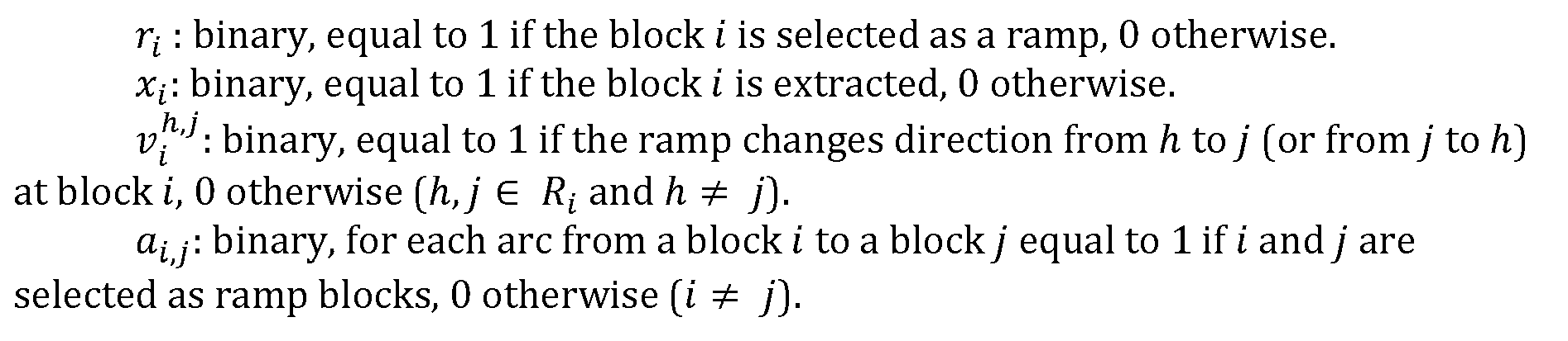
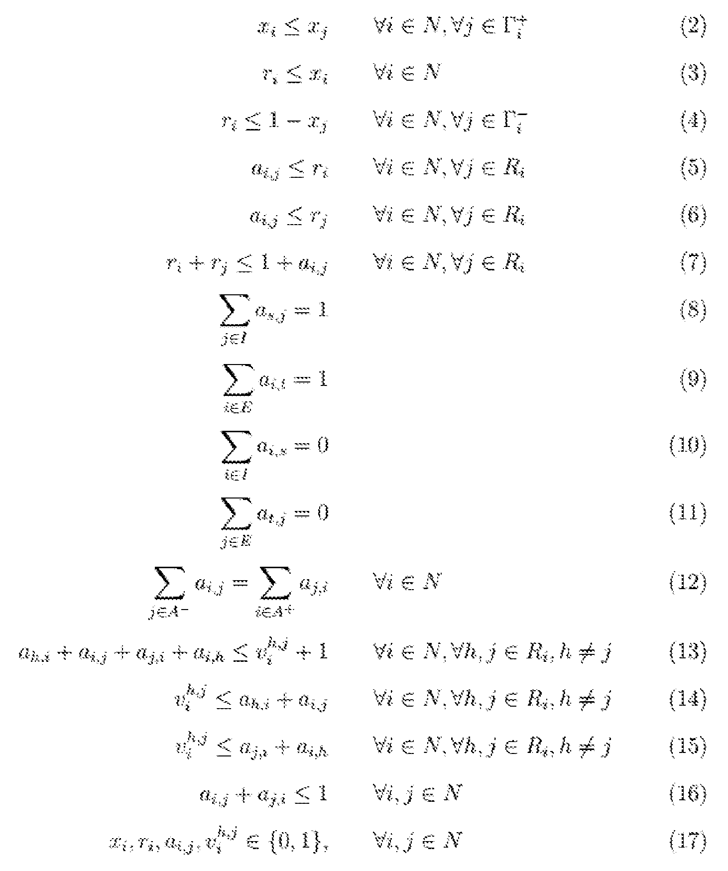
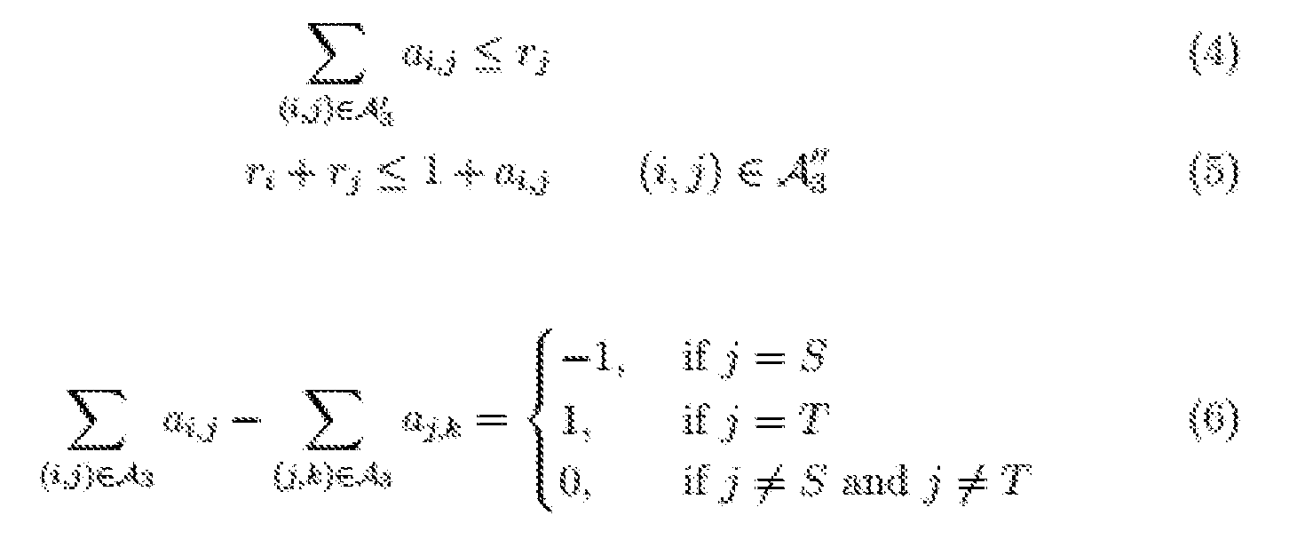
- Objective function (1) minimises the cost of the blocks extracted due to the ramp construction plus the cost of the changes of directions (switch-backs) in the ramp.
- Constraint (2 ⁇ ) ensures the vertical precedences in the extraction of any block.
- Constraint (3) imposes that every block flagged as ramp must be extracted. Constraint (4) avoids building a ramp in the air.
- Constraints (5) to (7) flag the blocks r t and h if only if the arc a ⁇ ; ⁇ is selected.
- Constraints (8) and (9) force one of the blocks in / and one of the blocks in E to be selected as a starting and finishing point for the ramp respectively.
- Constraints (10), (11) and (12) ensure the connectivity of the ramp.
- Constraints (13) to (15) identify the change of direction at each segment of the ramp.
- Constraint (16) avoids the ramp returning back to the same position.
- constraint (17) defines the scope of the variables. ln an alternative embodiment a binary linear model to find the minimum cost ramp is formulated.
- the inputs for the model are divided into two types: the geological inputs, which will include the geological block model, the topography, the contour of the pit, and the dependencies between blocks based on the required pit slopes; and operational inputs, which include various costs, the ramp width, and the set of possible starting and final points for the ramp.
- the geological model is assumed to be represented as a regularly spaced set of blocks (equal dimensions in coordinates x and y ), and must include the contour of the pit shape we are aiming to achieve. To reduce the size of the problem, blocks that are too far from the contour of the pit can be discarded.
- ramp width is equal to the block size in x (dx) or y (dy)) and the dimension in z (dz) represents the maximum ramp gradient.
- this may necessitate first dividing every block into several horizontal slices.
- the ramp is represented as a connected path of adjacent blocks from S to T (two artificial blocks that represent the starting and ending points of the ramp).
- the objective function 5 minimises the cost of the blocks extracted due to the ramp construction together with the haulage cost and those costs associated with changes of direction of the ramp.
- Constraint 1 ensures the vertical precedences are honoured in the extraction of any block.
- Constraint (2) ensures that every block flagged as part of the ramp must be extracted.
- Constraint ⁇ avoids building a ramp in the air.
- Constraints (4) to (5) flags the block j as belonging to the ramp if and only if the block i belongs to the ramp and the arc a ⁇ ; ⁇ has been selected. Constraint (6) ensures the connectivity of the ramp.
- Constraint (7) identifies the change of direction at each segment of the ramp.
- Constraint (8) defines the scope of the variables, all of which are binary.
- Embodiments of mine planning systems for example implemented in software executable in a computer system (either using stand-alone processing and memory hardware, cloud processing and memory resources, or a combination of both) can utilise any or all of the disclosed bubble model excavation, pushback, scheduling and ramp design methods within planning modules.
- Such systems 1100 can include:
- an input interface 1132 to enable input of user-controlled parameters, such as target tonnage for pushbacks, compactness factor, economic data etc;
- a data access interface 1145 for accessing databases 1140 or other storage repositories storing data such as mine block models, scheduling data, and optionally existing mine plans;
- processing 1110 and memory 1120 resources for executing one or more software modules for mine planning processes; such modules can include a clustering module 1150, scheduling module 1155, excavation module 1160, bubble pit pushback design modulell70, and a ramp design module 1165;
- an output interface 1135 to enable output of mine planning data to a user for assessment and use in implementation of a mine plan.
- the output interface may include a display module or a formatting module configured to prepare data in a format enabling output and display via external systems.
- the excavation module may be configured to implement planning for caving, stoping or other excavation embodiments.
- the mathematical model 1190 may be stored in system memory 1120 for application by the various modules. Resulting mine plans, designs or schedules generated by the system can be stored in memory 1120 or output via the user interface 1130. ln an embodiment the system may be implemented in a computer having a user interface 1130, processor 1110 and memory 1120.
- a computer, tablet or other device may be utilised as a user interface to access an online server implementing the system.
- Think or thick client embodiments may be utilised.
- the described mining design methods may be implemented in a software as a service embodiment, to enable existing mine designs (for example for mines already in operation) to be input to enable pushback and/or ramp redesign and optimisation for ongoing operations.
Landscapes
- Engineering & Computer Science (AREA)
- Business, Economics & Management (AREA)
- Mining & Mineral Resources (AREA)
- Human Resources & Organizations (AREA)
- Life Sciences & Earth Sciences (AREA)
- Physics & Mathematics (AREA)
- General Life Sciences & Earth Sciences (AREA)
- General Physics & Mathematics (AREA)
- Theoretical Computer Science (AREA)
- Geology (AREA)
- Strategic Management (AREA)
- Remote Sensing (AREA)
- Geochemistry & Mineralogy (AREA)
- Economics (AREA)
- Entrepreneurship & Innovation (AREA)
- Marketing (AREA)
- General Business, Economics & Management (AREA)
- Tourism & Hospitality (AREA)
- Quality & Reliability (AREA)
- Operations Research (AREA)
- Game Theory and Decision Science (AREA)
- Educational Administration (AREA)
- Development Economics (AREA)
- Geophysics (AREA)
- General Engineering & Computer Science (AREA)
- Geometry (AREA)
- Evolutionary Computation (AREA)
- Computer Hardware Design (AREA)
- Agronomy & Crop Science (AREA)
- Animal Husbandry (AREA)
- Marine Sciences & Fisheries (AREA)
- Health & Medical Sciences (AREA)
- General Health & Medical Sciences (AREA)
- Primary Health Care (AREA)
- Management, Administration, Business Operations System, And Electronic Commerce (AREA)
- Geophysics And Detection Of Objects (AREA)
Abstract
Description















Claims


Priority Applications (6)
| Application Number | Priority Date | Filing Date | Title |
|---|---|---|---|
| BR112020024085-0A BR112020024085A2 (en) | 2018-05-28 | 2019-05-28 | computer-implemented mine design and planning method and ramp design method |
| PE2020001915A PE20201442A1 (en) | 2018-05-28 | 2019-05-28 | MINE PLANNING METHOD AND SYSTEM |
| US17/058,536 US20210208305A1 (en) | 2018-05-28 | 2019-05-28 | Mine planning method and system |
| CA3100082A CA3100082A1 (en) | 2018-05-28 | 2019-05-28 | Mine planning method and system |
| AU2019277196A AU2019277196B2 (en) | 2018-05-28 | 2019-05-28 | Mine planning method and system |
| US18/818,515 US20250208314A1 (en) | 2018-05-28 | 2024-08-28 | Mine planning method and system |
Applications Claiming Priority (2)
| Application Number | Priority Date | Filing Date | Title |
|---|---|---|---|
| AU2018901873 | 2018-05-28 | ||
| AU2018901873A AU2018901873A0 (en) | 2018-05-28 | Mine planning method and system |
Related Child Applications (2)
| Application Number | Title | Priority Date | Filing Date |
|---|---|---|---|
| US17/058,536 A-371-Of-International US20210208305A1 (en) | 2018-05-28 | 2019-05-28 | Mine planning method and system |
| US18/818,515 Continuation US20250208314A1 (en) | 2018-05-28 | 2024-08-28 | Mine planning method and system |
Publications (1)
| Publication Number | Publication Date |
|---|---|
| WO2019227147A1 true WO2019227147A1 (en) | 2019-12-05 |
Family
ID=68696609
Family Applications (1)
| Application Number | Title | Priority Date | Filing Date |
|---|---|---|---|
| PCT/AU2019/050529 Ceased WO2019227147A1 (en) | 2018-05-28 | 2019-05-28 | Mine planning method and system |
Country Status (7)
| Country | Link |
|---|---|
| US (2) | US20210208305A1 (en) |
| AU (1) | AU2019277196B2 (en) |
| BR (1) | BR112020024085A2 (en) |
| CA (1) | CA3100082A1 (en) |
| CL (1) | CL2020003055A1 (en) |
| PE (1) | PE20201442A1 (en) |
| WO (1) | WO2019227147A1 (en) |
Cited By (3)
| Publication number | Priority date | Publication date | Assignee | Title |
|---|---|---|---|---|
| CN111583401A (en) * | 2020-03-21 | 2020-08-25 | 长沙迪迈数码科技股份有限公司 | Method, device and storage medium for processing boundary line of open-pit mine planning |
| CN113780698A (en) * | 2020-06-09 | 2021-12-10 | 中国石油化工股份有限公司 | Applicable to the evaluation method and electronic equipment of sandstone-type uranium resource potential in oil and gas areas |
| CN113807004A (en) * | 2021-06-30 | 2021-12-17 | 北京交通大学 | Tool life prediction method, device and system based on data mining |
Families Citing this family (15)
| Publication number | Priority date | Publication date | Assignee | Title |
|---|---|---|---|---|
| EP3924532B1 (en) | 2019-02-11 | 2026-03-25 | CCLabs Pty Ltd | A method of forming a diamond coating on a carbon material |
| US20210398157A1 (en) * | 2020-06-18 | 2021-12-23 | Colorado School Of Mines | Systems and methods for maximizing mine production scheduling |
| CN111611728B (en) * | 2020-06-29 | 2023-03-28 | 中国有色金属工业昆明勘察设计研究院有限公司 | Stability calculation method for Xigeda stratum rock slope trailing edge slip fracture surface position |
| CA3123401A1 (en) * | 2021-06-28 | 2022-12-28 | Pristine Mining Inc. | Method of trading in minerals |
| CN113705916B (en) * | 2021-09-01 | 2024-03-26 | 东北大学 | Multi-source multi-target ore blending method for strip mine iron ore |
| CN114154109A (en) * | 2021-11-11 | 2022-03-08 | 神华北电胜利能源有限公司 | Strip mine mining planning method and device under parallel propulsion mining stripping mode |
| CN114676468A (en) * | 2021-12-13 | 2022-06-28 | 东北大学 | A method and system for optimizing the final state of a metal open-pit mine |
| CN114810084B (en) * | 2022-05-07 | 2023-07-25 | 东北大学 | A method and system for open-pit coal mining with overall optimization of four elements |
| CN115146447B (en) * | 2022-06-10 | 2024-07-16 | 济南轨道交通集团有限公司 | Karst aquifer connectivity judging method, system, equipment and medium |
| CN116337012B (en) * | 2023-03-20 | 2023-10-20 | 重庆地质矿产研究院 | Optimization method for positioning boundary piles in open-pit mines based on oblique photogrammetry technology |
| CN117035157A (en) * | 2023-07-03 | 2023-11-10 | 中国地质大学(武汉) | Strip mine production plan optimization method based on copper price time sequence prediction |
| CN117874890B (en) * | 2024-01-19 | 2025-07-01 | 沈阳森普矿山工程设计有限公司 | Method for establishing optimal boundary of pit of strip mine and planning mining |
| CN117759245B (en) * | 2024-01-25 | 2024-07-23 | 河南建筑材料研究设计院有限责任公司 | Surface mine exploitation system and method using three-dimensional intelligent design |
| CN118607248A (en) * | 2024-06-21 | 2024-09-06 | 青海省第二地质勘查院 | A method for dynamic calculation of terrain changes and reserves before and after mining |
| CN119915350B (en) * | 2025-04-02 | 2025-07-04 | 赣南科技学院 | Mine safety monitoring information acquisition system and method |
Citations (4)
| Publication number | Priority date | Publication date | Assignee | Title |
|---|---|---|---|---|
| US20060190219A1 (en) * | 2002-10-09 | 2006-08-24 | Froyland Gary A | System and method(s) of mine planning, design and processing |
| US20060265342A1 (en) * | 2002-10-09 | 2006-11-23 | Froyland Gary A | System and method(s) of blended mine planning, design and processing |
| US20130262045A1 (en) * | 2012-03-28 | 2013-10-03 | Trimble Navigation Limited | Open pit mine designer |
| EP2896783A2 (en) * | 2013-12-19 | 2015-07-22 | Dassault Systemes Canada Software Inc. | Underground mining optimization |
-
2019
- 2019-05-28 BR BR112020024085-0A patent/BR112020024085A2/en unknown
- 2019-05-28 US US17/058,536 patent/US20210208305A1/en not_active Abandoned
- 2019-05-28 PE PE2020001915A patent/PE20201442A1/en unknown
- 2019-05-28 AU AU2019277196A patent/AU2019277196B2/en active Active
- 2019-05-28 WO PCT/AU2019/050529 patent/WO2019227147A1/en not_active Ceased
- 2019-05-28 CA CA3100082A patent/CA3100082A1/en active Pending
-
2020
- 2020-11-25 CL CL2020003055A patent/CL2020003055A1/en unknown
-
2024
- 2024-08-28 US US18/818,515 patent/US20250208314A1/en active Pending
Patent Citations (4)
| Publication number | Priority date | Publication date | Assignee | Title |
|---|---|---|---|---|
| US20060190219A1 (en) * | 2002-10-09 | 2006-08-24 | Froyland Gary A | System and method(s) of mine planning, design and processing |
| US20060265342A1 (en) * | 2002-10-09 | 2006-11-23 | Froyland Gary A | System and method(s) of blended mine planning, design and processing |
| US20130262045A1 (en) * | 2012-03-28 | 2013-10-03 | Trimble Navigation Limited | Open pit mine designer |
| EP2896783A2 (en) * | 2013-12-19 | 2015-07-22 | Dassault Systemes Canada Software Inc. | Underground mining optimization |
Non-Patent Citations (2)
| Title |
|---|
| BAI, X. ET AL.: "Automatic Generation of Feasible Mining Pushbacks for Open Pit Strategic Planning", JOURNAL OF THE SOUTHERN AFRICAN INSTITUTE OF MINING AND METALLURGY, May 2018 (2018-05-01), pages 515 - 530, XP055658370 * |
| MORALES, N. ET AL.: "An Integer Linear Programming Model for Optimizing Open Pit Ramp Design", M NP-APCOM, 2017, Retrieved from the Internet <URL:http://delphoslab.cl/Publicaciones/2017/MNPAPCOM2017.pdf> [retrieved on 20190815] * |
Cited By (3)
| Publication number | Priority date | Publication date | Assignee | Title |
|---|---|---|---|---|
| CN111583401A (en) * | 2020-03-21 | 2020-08-25 | 长沙迪迈数码科技股份有限公司 | Method, device and storage medium for processing boundary line of open-pit mine planning |
| CN113780698A (en) * | 2020-06-09 | 2021-12-10 | 中国石油化工股份有限公司 | Applicable to the evaluation method and electronic equipment of sandstone-type uranium resource potential in oil and gas areas |
| CN113807004A (en) * | 2021-06-30 | 2021-12-17 | 北京交通大学 | Tool life prediction method, device and system based on data mining |
Also Published As
| Publication number | Publication date |
|---|---|
| AU2019277196B2 (en) | 2025-04-17 |
| PE20201442A1 (en) | 2020-12-09 |
| AU2019277196A1 (en) | 2020-12-03 |
| CL2020003055A1 (en) | 2021-05-24 |
| BR112020024085A2 (en) | 2021-02-09 |
| CA3100082A1 (en) | 2019-12-05 |
| US20210208305A1 (en) | 2021-07-08 |
| US20250208314A1 (en) | 2025-06-26 |
Similar Documents
| Publication | Publication Date | Title |
|---|---|---|
| US20250208314A1 (en) | Mine planning method and system | |
| Ramazan | The new fundamental tree algorithm for production scheduling of open pit mines | |
| CN1723333B (en) | A method and device for determining the extraction of material from a mine having at least one mine shaft | |
| Yashar et al. | A multi-step approach for block-cave production scheduling optimization | |
| US7957941B2 (en) | System and method(s) of mine planning, design and processing | |
| Nhleko et al. | A review of underground stope boundary optimization algorithms | |
| Pourrahimian | Mathematical programming for sequence optimization in block cave mining | |
| Khodayari et al. | Mathematical programming applications in block-caving scheduling: a review of models and algorithms | |
| Smith et al. | Medium-term production scheduling of the Lumwana mining complex | |
| US20110227394A1 (en) | Method, Apparatus And Computer Program For Scheduling The Extraction Of A Resource And For Determining The Net Present Value Of An Extraction Schedule | |
| Dimitrakopoulos et al. | Stope design and geological uncertainty: quantification of risk in conventional designs and a probabilistic alternative | |
| Copland et al. | Integrated optimization of stope boundary selection and scheduling for sublevel stoping operations | |
| Mwangi et al. | Ultimate pit limit optimization methods in open pit mines: A review | |
| Bootsma et al. | Cut-off grade based sublevel stope mine optimisation: Introduction and evaluation of an optimisation approach and method for grade risk quantification | |
| Kumral et al. | Underground mine planning for stope-based methods | |
| Pourrahimian et al. | Mixed–Integer Linear Programming formulation for block–cave sequence optimisation | |
| Grieco et al. | Grade uncertainty in stope design—improving the optimisation process | |
| Appianing et al. | Underground mining stope layout optimization and production scheduling: a review of existing solvers and algorithms | |
| Ben-Awuah | Oil sands mine planning and waste management using goal programming | |
| Noriega et al. | Optimisation of the undercut level elevation in block caving mines using a mathematical programming framework | |
| Wang | Open pit production planning through pit generation and pit sequencing | |
| Afum | Open pit-underground mining options and transitions planning: a mathematical programming framework for optimal resource extraction evaluation | |
| Askari-Nasab et al. | Investigating continuous time open pit dynamics | |
| Shami-Qalandari et al. | Optimizing Stope Boundary and the Undercut Level in Block Cave Mining | |
| Kaydım | Long-term production scheduling optimization for a polymetallic open pit mine |
Legal Events
| Date | Code | Title | Description |
|---|---|---|---|
| 121 | Ep: the epo has been informed by wipo that ep was designated in this application |
Ref document number: 19810153 Country of ref document: EP Kind code of ref document: A1 |
|
| DPE1 | Request for preliminary examination filed after expiration of 19th month from priority date (pct application filed from 20040101) | ||
| ENP | Entry into the national phase |
Ref document number: 3100082 Country of ref document: CA |
|
| NENP | Non-entry into the national phase |
Ref country code: DE |
|
| ENP | Entry into the national phase |
Ref document number: 2019277196 Country of ref document: AU Date of ref document: 20190528 Kind code of ref document: A |
|
| REG | Reference to national code |
Ref country code: BR Ref legal event code: B01A Ref document number: 112020024085 Country of ref document: BR |
|
| ENP | Entry into the national phase |
Ref document number: 112020024085 Country of ref document: BR Kind code of ref document: A2 Effective date: 20201125 |
|
| 122 | Ep: pct application non-entry in european phase |
Ref document number: 19810153 Country of ref document: EP Kind code of ref document: A1 |