WO2019220570A1 - 活物質保持部材、電極及び鉛蓄電池 - Google Patents
活物質保持部材、電極及び鉛蓄電池 Download PDFInfo
- Publication number
- WO2019220570A1 WO2019220570A1 PCT/JP2018/018933 JP2018018933W WO2019220570A1 WO 2019220570 A1 WO2019220570 A1 WO 2019220570A1 JP 2018018933 W JP2018018933 W JP 2018018933W WO 2019220570 A1 WO2019220570 A1 WO 2019220570A1
- Authority
- WO
- WIPO (PCT)
- Prior art keywords
- cylindrical body
- active material
- electrode
- sealing member
- holding member
- Prior art date
- Legal status (The legal status is an assumption and is not a legal conclusion. Google has not performed a legal analysis and makes no representation as to the accuracy of the status listed.)
- Ceased
Links
Images


Classifications
-
- H—ELECTRICITY
- H01—ELECTRIC ELEMENTS
- H01M—PROCESSES OR MEANS, e.g. BATTERIES, FOR THE DIRECT CONVERSION OF CHEMICAL ENERGY INTO ELECTRICAL ENERGY
- H01M10/00—Secondary cells; Manufacture thereof
- H01M10/06—Lead-acid accumulators
- H01M10/12—Construction or manufacture
- H01M10/16—Suspending or supporting electrodes or groups of electrodes in the case
-
- H—ELECTRICITY
- H01—ELECTRIC ELEMENTS
- H01M—PROCESSES OR MEANS, e.g. BATTERIES, FOR THE DIRECT CONVERSION OF CHEMICAL ENERGY INTO ELECTRICAL ENERGY
- H01M4/00—Electrodes
- H01M4/02—Electrodes composed of, or comprising, active material
- H01M4/14—Electrodes for lead-acid accumulators
-
- H—ELECTRICITY
- H01—ELECTRIC ELEMENTS
- H01M—PROCESSES OR MEANS, e.g. BATTERIES, FOR THE DIRECT CONVERSION OF CHEMICAL ENERGY INTO ELECTRICAL ENERGY
- H01M4/00—Electrodes
- H01M4/02—Electrodes composed of, or comprising, active material
- H01M4/64—Carriers or collectors
- H01M4/70—Carriers or collectors characterised by shape or form
- H01M4/76—Containers for holding the active material, e.g. tubes, capsules
-
- Y—GENERAL TAGGING OF NEW TECHNOLOGICAL DEVELOPMENTS; GENERAL TAGGING OF CROSS-SECTIONAL TECHNOLOGIES SPANNING OVER SEVERAL SECTIONS OF THE IPC; TECHNICAL SUBJECTS COVERED BY FORMER USPC CROSS-REFERENCE ART COLLECTIONS [XRACs] AND DIGESTS
- Y02—TECHNOLOGIES OR APPLICATIONS FOR MITIGATION OR ADAPTATION AGAINST CLIMATE CHANGE
- Y02E—REDUCTION OF GREENHOUSE GAS [GHG] EMISSIONS, RELATED TO ENERGY GENERATION, TRANSMISSION OR DISTRIBUTION
- Y02E60/00—Enabling technologies; Technologies with a potential or indirect contribution to GHG emissions mitigation
- Y02E60/10—Energy storage using batteries
-
- Y—GENERAL TAGGING OF NEW TECHNOLOGICAL DEVELOPMENTS; GENERAL TAGGING OF CROSS-SECTIONAL TECHNOLOGIES SPANNING OVER SEVERAL SECTIONS OF THE IPC; TECHNICAL SUBJECTS COVERED BY FORMER USPC CROSS-REFERENCE ART COLLECTIONS [XRACs] AND DIGESTS
- Y02—TECHNOLOGIES OR APPLICATIONS FOR MITIGATION OR ADAPTATION AGAINST CLIMATE CHANGE
- Y02P—CLIMATE CHANGE MITIGATION TECHNOLOGIES IN THE PRODUCTION OR PROCESSING OF GOODS
- Y02P70/00—Climate change mitigation technologies in the production process for final industrial or consumer products
- Y02P70/50—Manufacturing or production processes characterised by the final manufactured product
Definitions
- the present invention relates to an active material holding member, an electrode, and a lead storage battery.
- Lead-acid batteries are widely used as secondary batteries for industrial or consumer use.
- lead-acid batteries for electric vehicles for example, lead-acid batteries for automobiles, so-called batteries
- UPS Uninterruptable Power Supply
- disaster prevention emergency
- lead-acid batteries for backup such as wireless and telephone.
- the electrode of the lead storage battery includes, for example, a cylindrical body, a core metal (current collector) inserted into the cylindrical body, and an electrode material filled between the cylindrical body and the core metal.
- Patent Document 1 discloses a woven fabric tube mainly composed of glass fiber or synthetic fiber as a cylindrical body.
- An object of the present invention is to provide an active material holding member and an electrode capable of improving the cycle characteristics of a lead storage battery. Moreover, an object of this invention is to provide the lead storage battery excellent in cycling characteristics.
- an active material holding member includes a cylindrical body that contains an active material, and a sealing member that seals at least one end of the cylindrical body, and the cylindrical body And the mutual relative position of the said sealing member is being fixed by the position shift prevention part.
- an active material is provided in a cylindrical body of an active material holding member that includes a cylindrical body that contains an active material and a sealing member that seals at least one end of the cylindrical body.
- the active material tends to be finer.
- the active material leaks from the gap and the cycle characteristics are deteriorated.
- the relative position of the cylindrical body and the sealing member shifts due to the expansion / contraction of the active material, the active material is likely to leak to the outside from between the cylindrical body and the sealing member, and the cycle characteristics deteriorate.
- Cheap if the relative position of the cylindrical body and the sealing member shifts due to the expansion / contraction of the active material, the active material is likely to leak to the outside from between the cylindrical body and the sealing member, and the cycle characteristics deteriorate.
- the relative positions of the cylindrical body and the sealing member are fixed by the misalignment prevention unit.
- the relative position between the cylindrical body and the sealing member is suppressed as charging and discharging are repeated, so that the active material is prevented from leaking to the outside from between the cylindrical body and the sealing member.
- the cycle characteristics of the lead-acid battery can be improved.
- One embodiment of the electrode according to the present invention includes the active material holding member described above. According to such an electrode, like the above-described active material holding member, the cycle characteristics of the lead storage battery can be improved.
- One embodiment of the lead storage battery according to the present invention includes the above-described electrode. Such a lead storage battery has excellent cycle characteristics.
- an active material holding member and an electrode capable of improving the cycle characteristics of a lead storage battery can be provided.
- the lead storage battery excellent in cycling characteristics can be provided.
- the lead acid battery according to the present embodiment includes the electrode according to the present embodiment.
- the electrode according to this embodiment includes the active material holding member according to this embodiment.
- the active material holding member according to the present embodiment is a member that holds an active material, and the “active material” includes both the active material after chemical conversion and the raw material of the active material before chemical conversion.
- the active material holding member according to the present embodiment includes a cylindrical body (active material holding tube, also referred to as “gauntlet”) that houses the active material, and a sealing member that seals at least one end of the cylindrical body. And the relative positions of the cylindrical body and the sealing member are fixed by the misalignment prevention unit. According to the active material holding member according to the present embodiment, since the relative position between the cylindrical body and the sealing member is suppressed as charging and discharging are repeated, the gap between the cylindrical body and the sealing member is suppressed. By suppressing the leakage of the active material to the outside, the cycle characteristics of the lead storage battery can be improved.
- the lead storage battery according to the present embodiment includes, for example, the electrode according to the present embodiment and a battery case that houses the electrode.
- the battery case is filled with an electrolytic solution.
- the electrode according to the present embodiment can be used as a positive electrode or a negative electrode, and the positive electrode or the negative electrode has an active material holding member.
- the electrode may constitute an electrode group.
- the electrode group includes a plurality of positive electrodes, a plurality of negative electrodes, and separators, and the positive electrodes and the negative electrodes are alternately arranged via the separators.
- the electrode (positive electrode or negative electrode) has a current collector and an electrode material (positive electrode material or negative electrode material) held by the current collector.
- the electrode material may contain a raw material of an active material as a material before chemical conversion, and may contain an active material as a material after chemical conversion.
- the positive electrode material contains a positive electrode active material after chemical conversion.
- the negative electrode material contains a negative electrode active material after chemical conversion.
- the positive electrode material after conversion can be obtained, for example, by forming an unconverted positive electrode material containing a raw material for the positive electrode active material.
- the positive electrode material after conversion can be obtained, for example, by aging and drying a positive electrode material paste containing a raw material of the positive electrode active material to obtain an unformed positive electrode material and then forming an unformed positive electrode material.
- Examples of the raw material for the positive electrode active material include lead powder and red lead.
- Examples of the positive electrode active material in the positive electrode material after chemical conversion include lead dioxide.
- the positive electrode material can further contain an additive as necessary.
- the additive for the positive electrode material include reinforcing short fibers.
- reinforcing short fibers include acrylic fibers, polyethylene fibers, polypropylene fibers, and polyethylene terephthalate fibers (PET fibers).
- the formed negative electrode material can be obtained by, for example, forming an unformed negative electrode material containing a raw material for the negative electrode active material.
- the negative electrode material after conversion can be obtained, for example, by forming an unformed negative electrode material by aging and drying a negative electrode material paste containing a raw material of the negative electrode active material and then forming an unformed negative electrode material.
- the raw material for the negative electrode active material include lead powder.
- Examples of the negative electrode active material in the negative electrode material after chemical conversion include porous spongy lead.
- the negative electrode material can further contain an additive as necessary.
- an additive for the negative electrode material a resin (sulfone group and / or sulfone) having at least one selected from the group consisting of barium sulfate, reinforcing short fibers, carbon material (carbonaceous conductive material), sulfone group and sulfonate group Resin having an acid base).
- the reinforcing short fiber the same reinforcing short fiber as that of the positive electrode material can be used.
- Examples of the carbon material include carbon black and graphite.
- Examples of carbon black include furnace black (Ketjen Black (registered trademark), etc.), channel black, acetylene black, thermal black, and the like.
- Examples of the resin having a sulfone group and / or a sulfonate group include lignin sulfonic acid, lignin sulfonate, and a condensate of phenols, aminoaryl sulfonic acid and formaldehyde.
- Examples of lignin sulfonate include alkali metal salts of lignin sulfonic acid.
- Examples of the phenols include bisphenol compounds such as bisphenol.
- Examples of aminoarylsulfonic acid include aminobenzenesulfonic acid and aminonaphthalenesulfonic acid.
- the material of the separator is not particularly limited as long as it is a material that prevents electrical connection between the positive electrode and the negative electrode and allows the electrolytic solution to pass therethrough.
- Examples of the material for the separator include microporous polyethylene; a mixture of glass fiber and synthetic resin.
- the active material holding member according to the present embodiment only needs to include at least one cylindrical body that stores the active material, and may include a plurality of cylindrical bodies.
- the number of the plurality of cylindrical bodies is, for example, 2 to 19.
- the active material holding member according to the present embodiment may include an active material holding tube group having a plurality of cylindrical bodies arranged side by side.
- a structure in which a plurality of cylindrical bodies are arranged side by side may be obtained by arranging cylindrical bodies that are separate from each other, and is obtained by forming a plurality of through-holes between mutually opposing substrates. May be.
- a connecting portion such as a seam (stitched portion) may be disposed between adjacent cylindrical bodies.
- the cross-sectional shape perpendicular to the axial direction of the cylindrical body may be a circle, an ellipse, a rounded square, or the like.
- the length of the cylindrical body is, for example, 160 to 400 mm.
- the outer diameter of the cylindrical body is, for example, 5 to 12 mm.
- the inner diameter of the cylindrical body is, for example, 5 to 10 mm.
- the thickness of the cylindrical body is, for example, 100 to 2000 ⁇ m.
- the cylindrical body is formed of a porous body and has pores.
- the cylindrical body may be formed of a base material such as a woven fabric or a non-woven fabric, for example.
- a material having acid resistance can be used.
- Base materials include polyolefin (polypropylene, polyethylene, etc.), polyethylene terephthalate (PET), polystyrene (PS), polyvinyl chloride (PVC), polyvinylidene chloride (PVDC), polyvinylidene fluoride (PVDF), polycarbonate (PC ); Inorganic materials such as glass fiber, silicon carbide, and alumina.
- the cylindrical body preferably includes a thermoplastic resin, and more preferably includes a polyolefin, from the viewpoint of easily improving cycle characteristics.
- resin may be held on the base material.
- the resin include acrylic resin, epoxy resin, phenol resin, melamine resin, and styrene resin.
- the resin may be held on the inner surface or outer surface of the substrate, or on the surface in the pores of the substrate, and may be attached on the substrate.
- the resin may be held on a part of the substrate or may be held on the whole of the substrate.
- the active material holding member according to the present embodiment can be used, for example, by arranging a metal core (current collector) and an electrode material containing an active material in a cylindrical body.
- the cored bar is a rod-shaped member that is inserted into the cylindrical body, and extends, for example, in the axial direction of the cylindrical body at the center of the cylindrical body.
- An electrode material (for example, a positive electrode material) containing an active material is filled between the cylindrical body and the core metal.
- the core metal can be obtained by casting, for example, by a pressure casting method.
- the constituent material of the core metal may be a conductive material, and examples thereof include lead alloys such as lead-calcium-tin alloy and lead-antimony-arsenic alloy.
- the lead alloy may contain selenium, silver, bismuth and the like.
- the cross-sectional shape perpendicular to the axial direction (longitudinal direction) of the core metal may be a circle, an ellipse, or the like.
- the length of the metal core is, for example, 170 to 400 mm.
- the diameter of the cored bar is, for example, 2.0 to 4.0 mm.
- the sealing member may be a member that seals at least one end portion of the cylindrical body.
- the sealing member seals the end portion disposed on the lower side in the vertical direction among the both end portions of the cylindrical body. Yes.
- the sealing member may be disposed inside the tubular body or may be disposed outside the tubular body.
- the sealing member may be fitted to at least one end of the cylindrical body.
- the active material may leak out from between the cylindrical body and the sealing member. Further suppression can further improve the cycle characteristics of the lead-acid battery.
- the material of the sealing member a material having acid resistance can be used.
- the material of the sealing member include resins such as polyolefin (polypropylene, polyethylene, etc.), polyethylene terephthalate (PET), polystyrene (PS), polyvinylidene fluoride (PVDF), polycarbonate (PC), and the like.
- the sealing member preferably includes a thermoplastic resin, more preferably includes a polyolefin, and further preferably includes a polypropylene, from the viewpoint of easily improving cycle characteristics. From the viewpoint of easily improving the cycle characteristics, it is preferable that the sealing member contains these materials when the cylindrical body contains polyolefin.
- the sealing member may be formed from the same material as the cylindrical body or may be formed from a material different from the cylindrical body.
- a fixing unit that fixes the cylindrical body and the sealing member
- a holding unit that holds the cylindrical body and / or the sealing member Etc.
- the adhering portion is disposed between the cylindrical body and the sealing member, and can include, for example, at least one selected from the group consisting of a fused portion and an adhesive portion.
- the fused portion is a portion formed by melting the cylindrical body and / or the sealing member, and the boundary portion between the cylindrical body and the sealing member may be integrated. Examples of the means for forming the fused portion include heating, ultrasonic irradiation, and laser irradiation.
- An adhesion part is a member different from a cylindrical body and a sealing member, and an adhesive agent etc. are mentioned.
- As the adhesive a thermosetting adhesive or the like can be used.
- the holding unit that holds the cylindrical body and / or the sealing member is, for example, a member that holds the cylindrical body and / or the sealing member without being disposed between the cylindrical body and the sealing member.
- a member separate from the cylindrical body and the sealing member can be used as the holding portion.
- Examples of the member connected to the battery case include a support member that is connected to the battery case and supports the sealing member. Specifically, the member on the bottom surface side of the battery case in the sealing member is supported. A support member etc. are mentioned.
- the support member may have a single or a plurality of protrusions extending in the axial direction (longitudinal direction, for example, the height direction of the battery case) of the cylindrical body.
- the support member may be in contact with the positive electrode, and the support member is not in contact with the negative electrode. It's okay.
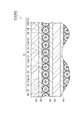
- FIG.1 and FIG.2 is sectional drawing which shows a lead storage battery typically.
- positive electrodes and negative electrodes are alternately arranged via separators from the front side to the back side of the drawing.
- FIG.1 (b) is an enlarged view which shows the area
- region P of Fig.1 (a) the illustration of the details inside the cylindrical body of the active material holding member is omitted.
- the lead storage battery shown in FIG. 1 and FIG. 2 includes a battery case extending in the vertical direction, and FIG. 1 shows a laminated structure of a negative electrode and a separator.
- the lead storage battery 100 shown in FIGS. 1 and 2 is connected to an electrode group 110, a battery case 120 that houses the electrode group 110, connecting members 130a and 130b connected to the electrode group 110, and connecting members 130a and 130b.
- the electrode poles 140a and 140b thus formed, a liquid plug 150 for closing the liquid injection port of the battery case 120, and a support member 160 connected to the battery case 120 are provided.
- the electrode group 110 includes a plurality of positive electrodes 10, a plurality of negative electrodes 20, and a plurality of separators 30.
- the positive electrode 10 and the negative electrode 20 are alternately arranged via the separator 30.
- the space around the positive electrode 10 between the separators 30 is filled with the electrolytic solution 40.
- the positive electrode 10 is, for example, a plate-like electrode (positive electrode plate), and includes an active material holding member 12, a core metal (current collector) 14, and a positive electrode material 16.
- the active material holding member 12 includes a plurality of cylindrical bodies 12a, a lower continuous seat (sealing member) 12b connected to one end of the cylindrical body 12a, and an upper continuous seat 12c connected to the other end of the cylindrical body 12a. And an ear portion 12d.
- the cored bar 14 extends in the axial direction of the cylindrical body 12a at the center of the cylindrical body 12a.
- the positive electrode material 16 is filled between the cylindrical body 12 a and the cored bar 14.
- the cylindrical body 12a, the cored bar 14, and the positive electrode material 16 constitute a cylindrical electrode (bar-shaped electrode).
- One end of the ear 12d is connected to the upper joint 12c, and the other end of the ear 12d is connected to the connecting member 130a.
- the cylindrical electrode of the positive electrode 10 is electrically connected to the pole column 140a via the upper continuous seat 12c, the ear portion 12d, and the connecting member 130a.
- the plurality of cylindrical bodies 12a in the active material holding member 12 are juxtaposed to each other and constitute an active material holding tube group.
- Each cylindrical body 12a extends in the height direction (vertical direction) of the battery case.
- the lower continuous seat 12b and the upper continuous seat 12c are in contact with the cylindrical body 12a and the cored bar 14 and the positive electrode material 16 disposed in the cylindrical body 12a, and the cylindrical body 12a, the cored bar 14 and the positive electrode material 16 Holding.
- the lower continuous seat 12b is attached to the end of the tubular body 12a on the bottom side of the battery case 120 (the end on the one end side of the tubular body 12a).
- the lower continuous seat 12b is fitted to the end of the cylindrical body 12a, is connected to the base that extends in a direction orthogonal to the axial direction of the cylindrical body 12a, and is connected to the end of the cylindrical body 12a.
- a plurality of fitting portions to be fitted to be fitted.
- the fitting portion is formed with a recess into which the end of the core bar 14 is inserted.
- the upper continuous seat 12c is attached to the upper end of the battery case 120 in the cylindrical body 12a (the other end of the cylindrical body 12a).
- the cylindrical body 12a and the lower joint 12b are fixed by a fixing portion 50 (see FIG. 1B).
- the support member 160 has a plurality of protrusions 160a extending in the axial direction (longitudinal direction, for example, the height direction of the battery case) of the cylindrical body 12a, and the lower continuous seat 12b is in contact with the plurality of protrusions 160a. It is fixed in contact (see FIG. 1 (a)). That is, the support member 160 supports the portion on the bottom surface side of the battery case 120 in the lower continuum 12b by each protrusion 160a. In this way, the relative positions of the cylindrical body 12a and the lower joint 12b are fixed by the fixing portion 50 and the support member 160, which are position shift prevention portions.
- the relative positions of the cylindrical body 12a and the upper continuous seat 12c may be fixed by a misalignment prevention portion (for example, a fixing portion), or may not be fixed by the misalignment prevention portion.
- the negative electrode 20 has a plate shape, for example, and is, for example, a paste type negative electrode plate.
- the negative electrode 20 includes a negative electrode current collector and a negative electrode material held by the negative electrode current collector.
- a plate-like current collector can be used as the negative electrode current collector.
- the compositions of the negative electrode current collector and the cored bar 14 of the positive electrode 10 may be the same or different from each other.
- the negative electrode 20 is electrically connected to the pole column 140b via the connecting member 130b.
- the active material holding member 12 includes a cylindrical body 12a that stores the active material, and a lower continuous seat 12b that seals one end of the cylindrical body 12a.
- the relative positions of the continuous seats 12 b are fixed by the fixing portion 50 and the support member 160. Therefore, in the lead storage battery 100, since the relative positions of the cylindrical body 12a and the lower continuous seat 12b are suppressed as charging and discharging are repeated, the active material is externally provided between the cylindrical body 12a and the lower continuous seat 12b. It is possible to improve the cycle characteristics of the lead-acid battery by suppressing leakage to the battery.
- the lower joint 12b is fitted to the end of the cylindrical body 12a.
- the cycle characteristics of the lead storage battery can be further improved.
- the lead acid battery manufacturing method includes, for example, an electrode manufacturing process for obtaining electrodes (positive electrode and negative electrode) and an assembling process for assembling components including the electrodes to obtain a lead acid battery.
- a positive electrode having a cylindrical body is obtained.
- the electrode manufacturing process includes, for example, a process A for obtaining a cylindrical body, a process B for sealing one end of the cylindrical body with a sealing member, a core metal, and an electrode material containing an active material in a cylindrical shape. And a step of sealing the other end of the cylindrical body with a sealing member after these steps.
- the process B may be performed before or after the process C.
- step A for example, first, two sheet-like base materials are prepared. Then, after these base materials are arranged to face each other, one base material and another base material are connected to each other by a plurality of substantially linear connecting portions (for example, stitching portions) arranged substantially at equal intervals. Connect. And between adjacent connection parts, between base materials is formed in a cylinder shape and a some through-hole is obtained. Thus, an active material holding tube group having a plurality of cylindrical bodies arranged in parallel to each other is obtained.
- a plurality of substantially linear connecting portions for example, stitching portions
- a method of obtaining a cylindrical body by forming a through hole between base materials between adjacent connecting portions a method of forming by inserting a rod-shaped body between base materials; impregnating the base material with a resin-containing liquid
- a method of expanding between the substrates at the time of drying after the treatment there may be mentioned a method of expanding between the substrates at the time of drying after the treatment.
- the resin When the resin is held on the base material of the cylindrical body, for example, after impregnating the cylindrical body with a liquid containing the resin (for example, an emulsion in which the resin is dispersed in water), for example, 1 at 60 to 130 ° C. Can be dried for ⁇ 3 hours.
- a liquid containing the resin for example, an emulsion in which the resin is dispersed in water
- step B for example, the end is sealed by fitting a sealing member to one end of the cylindrical body.
- step C for example, a slurry containing a solvent (water, organic solvent, etc.), sulfuric acid, and a raw material for the electrode material, and a core metal are supplied into the cylindrical body.
- An electrode having no cylindrical body (for example, a negative electrode) can be obtained by the following procedure. For example, after filling an electrode material paste containing an active material raw material into a current collector (for example, a current collector grid (casting grid, expanded grid, etc.)), aging and drying are performed to obtain an unformed electrode material.
- the electrode material paste may further contain, for example, the above-described additives in addition to the active material.
- the electrode material paste may further contain a solvent and sulfuric acid. Examples of the solvent include water and organic solvents.
- the aging can be performed, for example, in an atmosphere at a temperature of 35 to 85 ° C. and a humidity of 50 to 98 RH% for 15 to 60 hours. Drying can be carried out, for example, at a temperature of 45 to 80 ° C. for 15 to 30 hours.
- an unformed positive electrode and an unformed negative electrode are laminated via a separator, and a current collecting portion of the same polarity electrode is welded with a strap to obtain an electrode group.
- This electrode group is arranged in a battery case to produce an unformed battery.
- dilute sulfuric acid is put into an unformed battery and a direct current is applied to form a battery case.
- a lead acid battery can be obtained by adjusting the specific gravity of the sulfuric acid after conversion to an appropriate specific gravity.
- the specific gravity (before chemical conversion) of sulfuric acid is, for example, 1.100 to 1.260. Chemical conversion conditions and specific gravity of sulfuric acid can be adjusted according to the size of the electrode. Further, the chemical conversion treatment is not limited to being performed after the assembly process, and may be performed in the electrode manufacturing process (tank chemical conversion).
- At least one of the electrode manufacturing step and the assembly step includes a cylindrical body that houses the active material, and a sealing member that seals at least one end of the cylindrical body.
- the electrode manufacturing step includes a fixing step, for example, a fixing portion (a position shift prevention portion, a fusion portion, an adhesive portion, etc.) for fixing the cylindrical body and the sealing member is formed.
- a fixing portion for example, a position shift prevention portion, a fusion portion, an adhesive portion, etc.
- the fixing portion may be formed when one end portion of the cylindrical body is sealed with the sealing member.
- the fused part can be formed by heating, ultrasonic irradiation, laser irradiation or the like.
- the adhesion part can be formed by an adhesive or the like.
- the assembly process includes a fixing process
- the relative positions of the cylindrical body and the sealing member are fixed by a member connected to the battery case.
- the member connected to the battery case include a support member that supports the bottom side portion of the battery case in the sealing member.
- the sealing member may not be fitted to the end of the cylindrical body.
- the lower continuous seat 12b is not fitted to the end portion of the cylindrical body 12a, and the misalignment prevention portion such as the fixing portion 50 is the end portion of the cylindrical body 12a. May be sealed.
- the active material holding member 12 includes a fixing portion 50 as a sealing member.
- the active material holding member 12 of the above-described lead storage battery 100 includes the fixing portion 50 and the support member 160 as the misregistration prevention portion, but the active material holding member has at least one misregistration prevention portion. What is necessary is just to have only one of the adhering part and the supporting member.
- the misalignment prevention unit includes a member connected to the battery case (for example, the support member 160 described above), the cylindrical body 12a and the lower joint 12b are provided. It is not necessary to have a fixing portion to be fixed.
- the misalignment prevention unit does not have to include a member connected to the battery case as long as the misalignment prevention unit has a fixing part (for example, the above-described fixing part 50) that fixes the cylindrical body and the sealing member. .
- the lead acid battery according to the present embodiment can be used for an electric vehicle.
- the electric vehicle according to the present embodiment includes the lead storage battery according to the present embodiment.
- the manufacturing method of the electric vehicle which concerns on this embodiment is equipped with the process of obtaining a lead storage battery with the manufacturing method of the lead storage battery which concerns on this embodiment.
- the method for manufacturing an electric vehicle according to the present embodiment includes, for example, a step of obtaining a lead storage battery by the method of manufacturing a lead storage battery according to the present embodiment, and a step of assembling components including the lead storage battery to obtain an electric vehicle. ing.
- Examples of the electric vehicle include a forklift and a golf cart.
- an active material holding member, an electrode, and a lead storage battery used for an electric vehicle are provided.
- an active material holding member, an electrode, and a lead storage battery used for a forklift are provided.
- SYMBOLS 10 Positive electrode (electrode), 12 ... Active material holding member, 12a ... Cylindrical body, 12b ... Lower joint (sealing member), 50 ... Adhering part (position shift prevention part), 120 ... Battery case, 160 ... Support member (Position misalignment prevention part), 100 ... lead acid battery.
Landscapes
- Chemical & Material Sciences (AREA)
- Chemical Kinetics & Catalysis (AREA)
- Electrochemistry (AREA)
- General Chemical & Material Sciences (AREA)
- Engineering & Computer Science (AREA)
- Manufacturing & Machinery (AREA)
- Battery Electrode And Active Subsutance (AREA)
Abstract
活物質を収容する筒状体12aと、筒状体12aの一方の端部を封止する下部連座12bと、を備え、筒状体12a及び下部連座12bの互いの相対位置が固着部50及び支持部材160によって固定されている、活物質保持部材12。
Description
本発明は、活物質保持部材、電極及び鉛蓄電池に関する。
鉛蓄電池は、産業用又は民生用の二次電池として広く用いられており、特に、電気車用鉛蓄電池(例えば自動車用鉛蓄電池。いわゆるバッテリー)、又は、UPS(Uninterruptible Power Supply)、防災(非常)無線、電話等のバックアップ用鉛蓄電池の需要が多い。
鉛蓄電池の電極は、例えば、筒状体、筒状体内に挿入された芯金(集電体)、及び、筒状体と芯金との間に充填された電極材を備えている。例えば、下記特許文献1には、筒状体として、ガラス繊維又は合成繊維を主成分とする織布チューブが開示されている。
ところで、鉛蓄電池を長期間好適に使用するためには、優れたサイクル特性を達成することが重要であり、鉛蓄電池のサイクル特性を向上させることが求められている。
本発明は、鉛蓄電池のサイクル特性を向上させることが可能な活物質保持部材及び電極を提供することを目的とする。また、本発明は、サイクル特性に優れた鉛蓄電池を提供することを目的とする。
本発明に係る活物質保持部材の一実施形態は、活物質を収容する筒状体と、前記筒状体の少なくとも一方の端部を封止する封止部材と、を備え、前記筒状体及び前記封止部材の互いの相対位置が位置ずれ防止部によって固定されている。
本発明者の知見によれば、活物質を収容する筒状体と、筒状体の少なくとも一方の端部を封止する封止部材と、を備える活物質保持部材の筒状体に活物質を充填して得られた鉛蓄電池を繰り返し充放電させると、活物質が微細化する傾向がある。この場合、筒状体と封止部材との間に隙間が形成されると、当該隙間から活物質が漏出してサイクル特性が低下する。特に、活物質の膨張・収縮に伴い筒状体と封止部材との相対位置がずれると、筒状体と封止部材との間から活物質が外部に漏出しやすく、サイクル特性が低下しやすい。これに対し、本発明に係る活物質保持部材の一実施形態では、筒状体及び封止部材の互いの相対位置が位置ずれ防止部によって固定されている。これにより、充放電を繰り返すに伴い筒状体と封止部材との相対位置がずれることが抑制されるため、筒状体と封止部材との間から活物質が外部に漏出することが抑制されることにより鉛蓄電池のサイクル特性を向上させることができる。
本発明に係る電極の一実施形態は、上述の活物質保持部材を備える。このような電極によれば、上述の活物質保持部材と同様に、鉛蓄電池のサイクル特性を向上させることができる。
本発明に係る鉛蓄電池の一実施形態は、上述の電極を備える。このような鉛蓄電池は、優れたサイクル特性を有している。
本発明によれば、鉛蓄電池のサイクル特性を向上させることが可能な活物質保持部材及び電極を提供することができる。また、本発明によれば、サイクル特性に優れた鉛蓄電池を提供することができる。
以下、図面を適宜参照しながら、本発明の実施形態について説明する。但し、本発明は以下の実施形態に限定されるものではない。各図における構成要素の大きさは概念的なものであり、構成要素間の大きさの相対的な関係は各図に示されたものに限定されない。
<鉛蓄電池及びその製造方法>
本実施形態に係る鉛蓄電池は、本実施形態に係る電極を備える。本実施形態に係る電極は、本実施形態に係る活物質保持部材を備える。本実施形態に係る活物質保持部材は、活物質を保持する部材であり、「活物質」には、化成後の活物質及び化成前の活物質の原料の双方が包含される。
本実施形態に係る鉛蓄電池は、本実施形態に係る電極を備える。本実施形態に係る電極は、本実施形態に係る活物質保持部材を備える。本実施形態に係る活物質保持部材は、活物質を保持する部材であり、「活物質」には、化成後の活物質及び化成前の活物質の原料の双方が包含される。
本実施形態に係る活物質保持部材は、活物質を収容する筒状体(活物質保持用チューブ。「ガントレット」とも呼ばれる)と、筒状体の少なくとも一方の端部を封止する封止部材と、を備え、筒状体及び封止部材の互いの相対位置が位置ずれ防止部によって固定されている。本実施形態に係る活物質保持部材によれば、充放電を繰り返すに伴い筒状体と封止部材との相対位置がずれることが抑制されるため、筒状体と封止部材との間から活物質が外部に漏出することが抑制されることにより鉛蓄電池のサイクル特性を向上させることができる。
本実施形態に係る鉛蓄電池は、例えば、本実施形態に係る電極と、電極を収容する電槽と、を備える。電槽内は、電解液で満たされている。本実施形態に係る電極は、正極又は負極として用いることが可能であり、正極又は負極が活物質保持部材を有している。電極は、電極群を構成していてよい。例えば、電極群は、複数の正極と、複数の負極と、セパレータとを備えており、正極及び負極は、セパレータを介して交互に配置されている。
電極(正極又は負極)は、集電体と、集電体に保持された電極材(正極材又は負極材)とを有している。電極材は、化成前の材料として活物質の原料を含有していてもよく、化成後の材料として活物質を含有していてよい。正極材は、化成後において正極活物質を含有している。負極材は、化成後において負極活物質を含有している。
化成後の正極材は、例えば、正極活物質の原料を含む未化成の正極材を化成することで得ることができる。化成後の正極材は、例えば、正極活物質の原料を含む正極材ペーストを熟成及び乾燥することにより未化成の正極材を得た後に未化成の正極材を化成することで得ることができる。正極活物質の原料としては、鉛粉、鉛丹等が挙げられる。化成後の正極材における正極活物質としては、二酸化鉛等が挙げられる。
正極材は、必要に応じて添加剤を更に含有することができる。正極材の添加剤としては、補強用短繊維等が挙げられる。補強用短繊維としては、アクリル繊維、ポリエチレン繊維、ポリプロピレン繊維、ポリエチレンテレフタレート繊維(PET繊維)等が挙げられる。
化成後の負極材は、例えば、負極活物質の原料を含む未化成の負極材を化成することで得ることができる。化成後の負極材は、例えば、負極活物質の原料を含む負極材ペーストを熟成及び乾燥することにより未化成の負極材を得た後に未化成の負極材を化成することで得ることができる。負極活物質の原料としては、鉛粉等が挙げられる。化成後の負極材における負極活物質としては、多孔質の海綿状鉛(Spongy Lead)等が挙げられる。
負極材は、必要に応じて添加剤を更に含有することができる。負極材の添加剤としては、硫酸バリウム、補強用短繊維、炭素材料(炭素質導電材)、スルホン基及びスルホン酸塩基からなる群より選択される少なくとも一種を有する樹脂(スルホン基及び/又はスルホン酸塩基を有する樹脂)等が挙げられる。補強用短繊維としては、正極材と同様の補強用短繊維を用いることができる。
炭素材料としては、カーボンブラック、黒鉛等が挙げられる。カーボンブラックとしては、ファーネスブラック(ケッチェンブラック(登録商標)等)、チャンネルブラック、アセチレンブラック、サーマルブラックなどが挙げられる。
スルホン基及び/又はスルホン酸塩基を有する樹脂としては、リグニンスルホン酸、リグニンスルホン酸塩、フェノール類とアミノアリールスルホン酸とホルムアルデヒドとの縮合物等が挙げられる。リグニンスルホン酸塩としては、リグニンスルホン酸のアルカリ金属塩等が挙げられる。フェノール類としては、ビスフェノール等のビスフェノール系化合物などが挙げられる。アミノアリールスルホン酸としては、アミノベンゼンスルホン酸、アミノナフタレンスルホン酸等が挙げられる。
セパレータの材料としては、正極と負極との電気的な接続を阻止し、電解液を透過させる材料であれば特に限定されない。セパレータの材料としては、微多孔性ポリエチレン;ガラス繊維及び合成樹脂の混合物等が挙げられる。
本実施形態に係る活物質保持部材は、活物質を収容する筒状体を少なくとも一つ備えていればよく、複数の筒状体を備えていてよい。複数の筒状体の数は、例えば2~19である。本実施形態に係る活物質保持部材は、互いに並設された複数の筒状体を有する活物質保持用チューブ群を備えていてよい。複数の筒状体が互いに並設した構造は、互いに別体である筒状体を並設することにより得られてもよく、互いに対向する基材間に複数の貫通孔を形成することにより得られてもよい。隣接する筒状体間には、縫目(縫合部)等の接続部が配置されていてもよい。
筒状体の軸方向に垂直な断面形状は、円形、楕円形、角丸四角形等であってよい。筒状体の長さは、例えば160~400mmである。筒状体の外径は、例えば5~12mmである。筒状体の内径は、例えば5~10mmである。筒状体の厚さは、例えば100~2000μmである。
筒状体は、多孔質体で形成されており、細孔を有している。筒状体は、例えば、織布、不織布等の基材で形成されていてよい。基材の材料としては、耐酸性を有する材料を用いることができる。基材の材料としては、ポリオレフィン(ポリプロピレン、ポリエチレン等)、ポリエチレンテレフタレート(PET)、ポリスチレン(PS)、ポリ塩化ビニル(PVC)、ポリ塩化ビニリデン(PVDC)、ポリフッ化ビニリデン(PVDF)、ポリカーボネート(PC)等の樹脂;ガラス繊維、炭化ケイ素、アルミナ等の無機材料などが挙げられる。筒状体は、サイクル特性を向上させやすい観点から、熱可塑性樹脂を含むことが好ましく、ポリオレフィンを含むことがより好ましい。
筒状体では、基材上に樹脂が保持されていてよい。樹脂としては、アクリル樹脂、エポキシ樹脂、フェノール樹脂、メラミン樹脂、スチレン樹脂等が挙げられる。樹脂は、基材の内表面上若しくは外表面上、又は、基材における細孔内の表面上に保持されていてよく、基材上に付着していてよい。樹脂は、基材上の一部に保持されていてよく、基材上の全部に保持されていてよい。
本実施形態に係る活物質保持部材は、例えば、芯金(集電体)と、活物質を含む電極材と、を筒状体内に配置することにより用いることができる。芯金は、筒状体内に挿入される棒状部材であり、例えば、筒状体の中心部において筒状体の軸方向に伸びている。活物質を含む電極材(例えば正極材)は、筒状体及び芯金の間に充填されている。
芯金は、例えば、加圧鋳造法により鋳造して得ることができる。芯金の構成材料としては、導電性材料であればよく、例えば、鉛-カルシウム-錫系合金、鉛-アンチモン-ヒ素系合金等の鉛合金が挙げられる。鉛合金は、セレン、銀、ビスマス等を含んでいてよい。芯金の軸方向(長手方向)に垂直な断面形状は、円形、楕円形等であってよい。芯金の長さは、例えば170~400mmである。芯金の直径は、例えば2.0~4.0mmである。
封止部材は、筒状体の少なくとも一方の端部を封止する部材であればよく、例えば、筒状体の両端部のうち鉛直方向の下方側に配置される端部を封止している。封止部材は、筒状体の内部に配置されていてもよく、筒状体の外部に配置されていてもよい。複数の筒状体の端部を封止する場合、単一の封止部材によって複数の筒状体の端部を封止してもよく、複数の封止部材によって複数の筒状体の端部を封止してもよい。
封止部材は、筒状体の少なくとも一方の端部に嵌合していてよい。この場合、充放電を繰り返すに伴い筒状体と封止部材との相対位置がずれることが更に抑制されるため、筒状体と封止部材との間から活物質が外部に漏出することが更に抑制されることにより鉛蓄電池のサイクル特性を更に向上させることができる。
封止部材の材料としては、耐酸性を有する材料を用いることができる。封止部材の材料としては、ポリオレフィン(ポリプロピレン、ポリエチレン等)、ポリエチレンテレフタレート(PET)、ポリスチレン(PS)、ポリフッ化ビニリデン(PVDF)、ポリカーボネート(PC)等の樹脂などが挙げられる。封止部材は、サイクル特性を向上させやすい観点から、熱可塑性樹脂を含むことが好ましく、ポリオレフィンを含むことがより好ましく、ポリプロピレンを含むことが更に好ましい。サイクル特性を向上させやすい観点から、筒状体がポリオレフィンを含む場合において封止部材がこれらの材料を含むことが好ましい。封止部材は、筒状体と同一の材料から形成されていてよく、筒状体と異なる材料から形成されていてよい。
筒状体及び封止部材の互いの相対位置を固定する位置ずれ防止部としては、筒状体と封止部材とを固着する固着部;筒状体及び/又は封止部材を保持する保持部等が挙げられる。
固着部は、筒状体と封止部材との間に配置され、例えば、融着部及び接着部からなる群より選ばれる少なくとも一種を含むことができる。融着部は、筒状体及び/又は封止部材が溶融することにより形成された部分であり、筒状体及び封止部材の境界部分は一体化していてよい。融着部の形成手段としては、加熱、超音波照射、レーザー照射等が挙げられる。接着部は、筒状体及び封止部材とは異なる部材であり、接着剤等が挙げられる。接着剤としては、熱硬化性の接着剤等を用いることができる。
筒状体及び/又は封止部材を保持する保持部は、例えば、筒状体と封止部材との間に配置されることなく筒状体及び/又は封止部材を保持する部材である。保持部は、例えば、筒状体及び封止部材とは別体の部材を用いることができる。保持部としては、電槽の内壁(例えば底面);電槽(例えば底面)に接続された部材等が挙げられる。電槽に接続された部材としては、電槽に接続されていると共に封止部材を支持する支持部材等が挙げられ、具体的には、封止部材における電槽の底面側の部分を支持する支持部材等が挙げられる。支持部材は、筒状体の軸方向(長手方向。例えば電槽の高さ方向)に伸びる単一又は複数の突起部を有していてよい。活物質を収容する筒状体を正極が有し、且つ、活物質を収容する筒状体を負極が有しない場合、支持部材は正極に接していればよく、支持部材は負極に接していなくてよい。
図1及び図2を用いて、本実施形態に係る鉛蓄電池の一例を説明する。図1及び図2は、鉛蓄電池を模式的に示す断面図である。図1では、図面の手前側から奥側にかけて、セパレータを介して正極及び負極が交互に配置されている。図1(b)は、図1(a)の領域Pを示す拡大図である。図1(a)では、活物質保持部材の筒状体内の詳細の図示を省略している。図1及び図2に示される鉛蓄電池は、鉛直方向に伸びる電槽を備えており、図2は、鉛直方向の上方(電槽の高さ方向の上方)から鉛蓄電池を見た際の正極、負極及びセパレータの積層構造を示している。
図1及び図2に示される鉛蓄電池100は、電極群110と、電極群110を収容する電槽120と、電極群110に接続された連結部材130a,130bと、連結部材130a,130bに接続された極柱140a,140bと、電槽120の注液口を閉塞する液口栓150と、電槽120に接続された支持部材160と、を備えている。
電極群110は、複数の正極10と、複数の負極20と、複数のセパレータ30とを備えている。正極10及び負極20は、セパレータ30を介して交互に配置されている。セパレータ30間における正極10の周囲の空間には、電解液40が充填されている。
正極10は、例えば、板状の電極(正極板)であり、活物質保持部材12と、芯金(集電体)14と、正極材16と、を有している。活物質保持部材12は、複数の筒状体12aと、筒状体12aの一端に接続された下部連座(封止部材)12bと、筒状体12aの他端に接続された上部連座12cと、耳部12dとを有している。
芯金14は、筒状体12aの中心部において筒状体12aの軸方向に伸びている。正極材16は、筒状体12a及び芯金14の間に充填されている。筒状体12a、芯金14及び正極材16は筒状電極(棒状電極)を構成している。耳部12dの一端は上部連座12cに接続され、耳部12dの他端は連結部材130aに接続されている。正極10の筒状電極は、上部連座12c、耳部12d及び連結部材130aを介して極柱140aに電気的に接続されている。
活物質保持部材12における複数の筒状体12aは、互いに並設されており、活物質保持用チューブ群を構成している。各筒状体12aは、電槽の高さ方向(鉛直方向)に伸びている。
下部連座12b及び上部連座12cは、筒状体12aと、筒状体12a内に配置された芯金14及び正極材16とに接しており、筒状体12aと芯金14と正極材16とを保持している。下部連座12bは、筒状体12aにおける電槽120の底部側の端部(筒状体12aの一端側の末端)に取り付けられている。下部連座12bは、筒状体12aの端部に嵌合しており、筒状体12aの軸方向に直交する方向に伸びる基部と、当該基部に接続されると共に筒状体12aの端部に嵌合する複数の嵌合部とを有している。嵌合部には、芯金14の端部が差し込まれる凹部が形成されている。上部連座12cは、筒状体12aにおける電槽120の上部側の端部(筒状体12aの他端側の末端)に取り付けられている。
活物質保持部材12において筒状体12a及び下部連座12bは固着部50によって固定されている(図1(b)参照)。また、支持部材160は、筒状体12aの軸方向(長手方向。例えば電槽の高さ方向)に伸びる複数の突起部160aを有しており、下部連座12bは複数の突起部160aに当接して固定されている(図1(a)参照)。すなわち、支持部材160は、下部連座12bにおける電槽120の底面側の部分を各突起部160aによって支持している。このように、筒状体12a及び下部連座12bの互いの相対位置が、位置ずれ防止部である固着部50及び支持部材160によって固定されている。筒状体12a及び上部連座12cの互いの相対位置は、位置ずれ防止部(例えば固着部)によって固定されていてもよく、位置ずれ防止部によって固定されていなくてもよい。
負極20は、例えば板状であり、例えばペースト式負極板である。負極20は、負極集電体と、当該負極集電体に保持された負極材と、を有する。負極集電体としては、板状の集電体を用いることができる。負極集電体、及び、正極10の芯金14の組成は、互いに同一であってよく、互いに異なっていてよい。負極20は、連結部材130bを介して極柱140bに電気的に接続されている。
鉛蓄電池100では、活物質保持部材12が、活物質を収容する筒状体12aと、筒状体12aの一方の端部を封止する下部連座12bと、を備え、筒状体12a及び下部連座12bの互いの相対位置が固着部50及び支持部材160によって固定されている。そのため、鉛蓄電池100では、充放電を繰り返すに伴い筒状体12aと下部連座12bとの相対位置がずれることが抑制されるため、筒状体12aと下部連座12bとの間から活物質が外部に漏出することが抑制されることにより鉛蓄電池のサイクル特性を向上させることができる。
また、鉛蓄電池100では、下部連座12bが筒状体12aの端部に嵌合している。この場合、筒状体12a及び下部連座12bの互いの相対位置が更に固定されるため、鉛蓄電池のサイクル特性を更に向上させることができる。
次に、鉛蓄電池の製造方法について説明する。本実施形態に係る鉛蓄電池の製造方法は、例えば、電極(正極及び負極)を得る電極作製工程と、電極を含む構成部材を組み立てて鉛蓄電池を得る組み立て工程とを備える。
電極作製工程では、例えば、筒状体を有する正極を得る。電極作製工程は、例えば、筒状体を得る工程Aと、筒状体の一方の端部を封止部材により封止する工程Bと、芯金、及び、活物質を含む電極材を筒状体内に配置する工程Cと、を備え、これらの工程の後に、筒状体の他方の端部を封止部材により封止する工程を備えていてよい。工程Bは、工程Cの前後のいずれに行ってもよい。
工程Aでは、例えば、まず、シート状の2枚の基材を用意する。そして、これらの基材を互いに対向配置させた後、略等間隔をおいて配置された互いに略平行な複数の直線状の接続部(例えば縫合部)によって一の基材と他の基材とを接続する。そして、隣接する接続部間において、基材間を筒状に形成して複数の貫通孔を得る。これにより、互いに並設された複数の筒状体を有する活物質保持用チューブ群が得られる。
隣接する接続部間において、基材間に貫通孔を形成して筒状体を得る方法としては、基材間に棒状体を挿入して成形する方法;樹脂を含有する液を基材に含浸させた後の乾燥時に基材間を膨張させる方法等が挙げられる。
筒状体の基材上に樹脂を保持させる場合、例えば、樹脂を含有する液(例えば、樹脂を水に分散させたエマルジョン)を筒状体に含浸させた後、例えば60~130℃で1~3時間乾燥させることができる。
工程Bでは、例えば、筒状体の一方の端部に封止部材を嵌合させることにより当該端部を封止する。工程Cでは、例えば、溶媒(水、有機溶媒等)、硫酸、及び、電極材の原料を含むスラリーと、芯金とを筒状体内に供給する。
筒状体を有しない電極(例えば負極)は下記の手順により得ることができる。例えば、活物質の原料を含む電極材ペーストを集電体(例えば集電体格子(鋳造格子体、エキスパンド格子体等))に充填した後に熟成及び乾燥を行うことにより、未化成の電極材を有する電極を得ることができる。電極材ペーストは、例えば、活物質の原料に加えて、上述した添加剤を更に含んでいてよい。電極材ペーストは、溶媒及び硫酸を更に含んでいてよい。溶媒としては、例えば、水及び有機溶媒が挙げられる。熟成は、例えば、温度35~85℃、湿度50~98RH%の雰囲気で15~60時間実施することができる。乾燥は、例えば、温度45~80℃で15~30時間実施することができる。
組み立て工程では、例えば、セパレータを介して未化成の正極及び未化成の負極を積層すると共に、同極性の電極の集電部をストラップで溶接させて電極群を得る。この電極群を電槽内に配置して未化成の電池を作製する。次に、未化成の電池に希硫酸を入れて直流電流を通電して電槽化成する。化成後の硫酸の比重を適切な比重に調整することにより鉛蓄電池が得られる。硫酸の比重(化成前)は、例えば1.100~1.260である。化成条件及び硫酸の比重は、電極のサイズに応じて調整することができる。また、化成処理は、組み立て工程後に実施されることに限られず、電極作製工程において実施されてよい(タンク化成)。
本実施形態に係る鉛蓄電池の製造方法では、電極作製工程及び組み立て工程の少なくとも一方が、活物質を収容する筒状体と、筒状体の少なくとも一方の端部を封止する封止部材との互いの相対位置を位置ずれ防止部によって固定する固定工程を有している。
電極作製工程が固定工程を有する場合、例えば、筒状体と封止部材とを固着する固着部(位置ずれ防止部。融着部、接着部等)を形成する。上述の工程Bにおいて、筒状体の一方の端部を封止部材により封止する際に固着部を形成してもよい。融着部は、加熱、超音波照射、レーザー照射等により形成できる。接着部は、接着剤等により形成できる。
組み立て工程が固定工程を有する場合、例えば、電槽に接続された部材によって筒状体及び封止部材の互いの相対位置を固定する。電槽に接続された部材としては、封止部材における電槽の底面側の部分を支持する支持部材等が挙げられる。
以上、鉛蓄電池及びその製造方法の実施形態について説明したが、本発明は上述の実施形態に限定されない。
例えば、封止部材は、筒状体の端部に嵌合していなくてもよい。具体的には、図3(a)に示すように、筒状体12aの端部に下部連座12bが嵌合することなく、固着部50等の位置ずれ防止部が筒状体12aの端部を封止していてもよい。この場合、活物質保持部材12は、封止部材として固着部50を備えている。
また、上述の鉛蓄電池100の活物質保持部材12は、位置ずれ防止部として固着部50及び支持部材160を備えているが、活物質保持部材は、少なくとも一つの位置ずれ防止部を有していればよく、固着部及び支持部材の一方のみを有していてよい。例えば、図3(b)に示すように、位置ずれ防止部は、電槽に接続された部材(例えば、上述の支持部材160)を備えていれば、筒状体12aと下部連座12bとを固着する固着部を有していなくてよい。また、位置ずれ防止部は、筒状体と封止部材とを固着する固着部(例えば、上述の固着部50)を有していれば、電槽に接続された部材を備えていなくてよい。
<電気車>
本実施形態に係る鉛蓄電池は、電気車に用いることができる。本実施形態に係る電気車は、本実施形態に係る鉛蓄電池を備える。本実施形態に係る電気車の製造方法は、本実施形態に係る鉛蓄電池の製造方法により鉛蓄電池を得る工程を備える。本実施形態に係る電気車の製造方法は、例えば、本実施形態に係る鉛蓄電池の製造方法により鉛蓄電池を得る工程と、前記鉛蓄電池を含む構成部材を組み立てて電気車を得る工程とを備えている。電気車としては、フォークリフト、ゴルフカート等が挙げられる。本実施形態によれば、電気車に用いられる活物質保持部材、電極及び鉛蓄電池が提供され、例えば、フォークリフトに用いられる活物質保持部材、電極及び鉛蓄電池が提供される。
本実施形態に係る鉛蓄電池は、電気車に用いることができる。本実施形態に係る電気車は、本実施形態に係る鉛蓄電池を備える。本実施形態に係る電気車の製造方法は、本実施形態に係る鉛蓄電池の製造方法により鉛蓄電池を得る工程を備える。本実施形態に係る電気車の製造方法は、例えば、本実施形態に係る鉛蓄電池の製造方法により鉛蓄電池を得る工程と、前記鉛蓄電池を含む構成部材を組み立てて電気車を得る工程とを備えている。電気車としては、フォークリフト、ゴルフカート等が挙げられる。本実施形態によれば、電気車に用いられる活物質保持部材、電極及び鉛蓄電池が提供され、例えば、フォークリフトに用いられる活物質保持部材、電極及び鉛蓄電池が提供される。
10…正極(電極)、12…活物質保持部材、12a…筒状体、12b…下部連座(封止部材)、50…固着部(位置ずれ防止部)、120…電槽、160…支持部材(位置ずれ防止部)、100…鉛蓄電池。
Claims (9)
- 活物質を収容する筒状体と、
前記筒状体の少なくとも一方の端部を封止する封止部材と、を備え、
前記筒状体及び前記封止部材の互いの相対位置が位置ずれ防止部によって固定されている、活物質保持部材。 - 前記位置ずれ防止部が、前記筒状体と前記封止部材とを固着する固着部を有する、請求項1に記載の活物質保持部材。
- 前記固着部が、融着部及び接着部からなる群より選ばれる少なくとも一種を含む、請求項2に記載の活物質保持部材。
- 前記封止部材が前記端部に嵌合している、請求項1~3のいずれか一項に記載の活物質保持部材。
- 前記筒状体がポリオレフィンを含む、請求項1~4のいずれか一項に記載の活物質保持部材。
- 前記封止部材がポリオレフィンを含む、請求項1~5のいずれか一項に記載の活物質保持部材。
- 請求項1~6のいずれか一項に記載の活物質保持部材を備える、電極。
- 請求項7に記載の電極を備える、鉛蓄電池。
- 前記電極を収容する電槽を更に備え、
前記位置ずれ防止部として、前記電槽に接続されていると共に前記封止部材を支持する部材を備える、請求項8に記載の鉛蓄電池。
Priority Applications (1)
| Application Number | Priority Date | Filing Date | Title |
|---|---|---|---|
| PCT/JP2018/018933 WO2019220570A1 (ja) | 2018-05-16 | 2018-05-16 | 活物質保持部材、電極及び鉛蓄電池 |
Applications Claiming Priority (1)
| Application Number | Priority Date | Filing Date | Title |
|---|---|---|---|
| PCT/JP2018/018933 WO2019220570A1 (ja) | 2018-05-16 | 2018-05-16 | 活物質保持部材、電極及び鉛蓄電池 |
Publications (1)
| Publication Number | Publication Date |
|---|---|
| WO2019220570A1 true WO2019220570A1 (ja) | 2019-11-21 |
Family
ID=68539851
Family Applications (1)
| Application Number | Title | Priority Date | Filing Date |
|---|---|---|---|
| PCT/JP2018/018933 Ceased WO2019220570A1 (ja) | 2018-05-16 | 2018-05-16 | 活物質保持部材、電極及び鉛蓄電池 |
Country Status (1)
| Country | Link |
|---|---|
| WO (1) | WO2019220570A1 (ja) |
Citations (2)
| Publication number | Priority date | Publication date | Assignee | Title |
|---|---|---|---|---|
| JPS5273423U (ja) * | 1975-11-28 | 1977-06-01 | ||
| JPH0295159U (ja) * | 1989-01-12 | 1990-07-30 |
-
2018
- 2018-05-16 WO PCT/JP2018/018933 patent/WO2019220570A1/ja not_active Ceased
Patent Citations (2)
| Publication number | Priority date | Publication date | Assignee | Title |
|---|---|---|---|---|
| JPS5273423U (ja) * | 1975-11-28 | 1977-06-01 | ||
| JPH0295159U (ja) * | 1989-01-12 | 1990-07-30 |
Similar Documents
| Publication | Publication Date | Title |
|---|---|---|
| KR102898379B1 (ko) | 개선된 납 축전지 분리기, 전극, 배터리 그리고 그 제조 방법 및 그 용도 | |
| CN114830384B (zh) | 活性物质保持部件、电极及铅蓄电池 | |
| KR100953890B1 (ko) | 쿼지바이폴라 구조를 갖는 전기화학셀 | |
| JPH0366782B2 (ja) | ||
| KR102201100B1 (ko) | 클래드 튜브, 클래드식 전극, 납 축전지 및 이들의 제조 방법, 그리고 전동차 | |
| KR20200096967A (ko) | 활물질 보유용 튜브, 활물질 보유용 튜브군, 전극 및 납축전지 | |
| JP6947311B2 (ja) | 鉛蓄電池の製造方法 | |
| JP7653407B2 (ja) | 活物質保持部材及びその製造方法、電極、鉛蓄電池、マイクロハイブリッド車、並びに、電動車 | |
| JP7653237B2 (ja) | 集電体、電極、鉛蓄電池、組電池及び電動車 | |
| JP7791711B2 (ja) | 鉛蓄電池 | |
| JP7282642B2 (ja) | 封止部材、電極、鉛蓄電池及び電極製造方法 | |
| JP7689423B2 (ja) | 電極及び鉛蓄電池 | |
| JP6915752B2 (ja) | 活物質保持部材及びその製造方法、電極、鉛蓄電池、並びに、電動車 | |
| WO2021053772A1 (ja) | 電極、鉛蓄電池、集電体及び集電体の製造方法 | |
| JP7594537B2 (ja) | 活物質保持部材、電極、鉛蓄電池及び電動車 | |
| JP2022057331A (ja) | 集電体、電極、鉛蓄電池、組電池及び電動車 | |
| WO2021053767A1 (ja) | 封止部材、電極及び鉛蓄電池 | |
| JP2023096374A (ja) | 電極及び鉛蓄電池 | |
| JP7421563B2 (ja) | 電極、鉛蓄電池、集電体及び集電体の製造方法 | |
| EP0117238B1 (en) | Sandwich electrode and a battery comprising the same | |
| WO2019159287A1 (ja) | 活物質保持用チューブ、電極及び鉛蓄電池 | |
| WO2021019958A1 (ja) | 樹脂部材、活物質保持部材、電極、鉛蓄電池及び電動車 | |
| JP2022103916A (ja) | 活物質保持部材、電極及び鉛蓄電池 | |
| JP2022103939A (ja) | 活物質保持部材、電極及び鉛蓄電池 | |
| JP2022103976A (ja) | 鉛蓄電池 |
Legal Events
| Date | Code | Title | Description |
|---|---|---|---|
| 121 | Ep: the epo has been informed by wipo that ep was designated in this application |
Ref document number: 18919355 Country of ref document: EP Kind code of ref document: A1 |
|
| NENP | Non-entry into the national phase |
Ref country code: DE |
|
| 122 | Ep: pct application non-entry in european phase |
Ref document number: 18919355 Country of ref document: EP Kind code of ref document: A1 |
|
| NENP | Non-entry into the national phase |
Ref country code: JP |