WO2019203214A1 - 収納ボックス - Google Patents
収納ボックス Download PDFInfo
- Publication number
- WO2019203214A1 WO2019203214A1 PCT/JP2019/016265 JP2019016265W WO2019203214A1 WO 2019203214 A1 WO2019203214 A1 WO 2019203214A1 JP 2019016265 W JP2019016265 W JP 2019016265W WO 2019203214 A1 WO2019203214 A1 WO 2019203214A1
- Authority
- WO
- WIPO (PCT)
- Prior art keywords
- movable lid
- shaft
- lid
- rail
- vehicle
- Prior art date
- Legal status (The legal status is an assumption and is not a legal conclusion. Google has not performed a legal analysis and makes no representation as to the accuracy of the status listed.)
- Ceased
Links
Images


Classifications
-
- B—PERFORMING OPERATIONS; TRANSPORTING
- B60—VEHICLES IN GENERAL
- B60N—SEATS SPECIALLY ADAPTED FOR VEHICLES; VEHICLE PASSENGER ACCOMMODATION NOT OTHERWISE PROVIDED FOR
- B60N2/00—Seats specially adapted for vehicles; Arrangement or mounting of seats in vehicles
- B60N2/75—Arm-rests
- B60N2/79—Adaptations for additional use of the arm-rests
-
- B—PERFORMING OPERATIONS; TRANSPORTING
- B60—VEHICLES IN GENERAL
- B60N—SEATS SPECIALLY ADAPTED FOR VEHICLES; VEHICLE PASSENGER ACCOMMODATION NOT OTHERWISE PROVIDED FOR
- B60N3/00—Arrangements or adaptations of other passenger fittings, not otherwise provided for
- B60N3/12—Arrangements or adaptations of other passenger fittings, not otherwise provided for of receptacles for cigarettes or the like
-
- B—PERFORMING OPERATIONS; TRANSPORTING
- B60—VEHICLES IN GENERAL
- B60R—VEHICLES, VEHICLE FITTINGS, OR VEHICLE PARTS, NOT OTHERWISE PROVIDED FOR
- B60R7/00—Stowing or holding appliances inside vehicle primarily intended for personal property smaller than suit-cases, e.g. travelling articles, or maps
- B60R7/04—Stowing or holding appliances inside vehicle primarily intended for personal property smaller than suit-cases, e.g. travelling articles, or maps in driver or passenger space, e.g. using racks
-
- E—FIXED CONSTRUCTIONS
- E05—LOCKS; KEYS; WINDOW OR DOOR FITTINGS; SAFES
- E05B—LOCKS; ACCESSORIES THEREFOR; HANDCUFFS
- E05B83/00—Vehicle locks specially adapted for particular types of wing or vehicle
- E05B83/28—Locks for glove compartments, console boxes, fuel inlet covers or the like
- E05B83/32—Locks for glove compartments, console boxes, fuel inlet covers or the like for console boxes, e.g. between passenger seats
-
- E—FIXED CONSTRUCTIONS
- E05—LOCKS; KEYS; WINDOW OR DOOR FITTINGS; SAFES
- E05C—BOLTS OR FASTENING DEVICES FOR WINGS, SPECIALLY FOR DOORS OR WINDOWS
- E05C19/00—Other devices specially designed for securing wings, e.g. with suction cups
- E05C19/006—Other devices specially designed for securing wings, e.g. with suction cups by displacement of the wing substantially in its own plane
-
- E—FIXED CONSTRUCTIONS
- E05—LOCKS; KEYS; WINDOW OR DOOR FITTINGS; SAFES
- E05C—BOLTS OR FASTENING DEVICES FOR WINGS, SPECIALLY FOR DOORS OR WINDOWS
- E05C9/00—Arrangements of simultaneously actuated bolts or other securing devices at well-separated positions on the same wing
- E05C9/04—Arrangements of simultaneously actuated bolts or other securing devices at well-separated positions on the same wing with two sliding bars moved in opposite directions when fastening or unfastening
- E05C9/045—Arrangements of simultaneously actuated bolts or other securing devices at well-separated positions on the same wing with two sliding bars moved in opposite directions when fastening or unfastening with inclined surfaces, e.g. spiral or helicoidal
-
- B—PERFORMING OPERATIONS; TRANSPORTING
- B60—VEHICLES IN GENERAL
- B60R—VEHICLES, VEHICLE FITTINGS, OR VEHICLE PARTS, NOT OTHERWISE PROVIDED FOR
- B60R11/00—Arrangements for holding or mounting articles, not otherwise provided for
- B60R2011/0001—Arrangements for holding or mounting articles, not otherwise provided for characterised by position
- B60R2011/0003—Arrangements for holding or mounting articles, not otherwise provided for characterised by position inside the vehicle
- B60R2011/0007—Mid-console
Definitions
- the present invention relates to a storage box used as a console box of a vehicle.
- a storage box such as a console box
- a storage box such as a console box
- Patent Document 1 discloses a storage box configured such that a lid body is fully opened from a fully closed state through a sliding operation and a rotating operation, and an opening of a box body is opened.
- a cover is stored inside the box body.
- the storage box of the present invention made to solve the above problems includes a box body having an opening on the vehicle upper side, a fixed lid disposed on the vehicle rear side of the opening, and the vehicle front side of the opening.
- a support member having a lid having a movable lid disposed on the vehicle, a first shaft provided on the vehicle front side of the movable lid, and a second shaft provided on the vehicle rear side of the movable lid;
- the rail has an inclined portion that guides the second shaft so that the movable lid advances toward the inside of the box body with respect to the fixed lid when the movable lid starts the sliding operation from the fully closed position; And a guide portion that continuously extends from the inclined portion and guides the second shaft so that the movable lid advances to the fully open position.
- the second rail guides the second shaft so that the movable lid advances toward the inside of the box body with respect to the fixed lid when the movable lid starts the sliding operation from the fully closed position. It has an inclined part. Thereby, the movable lid can be smoothly slid from the fully closed position to the inside of the box body of the fixed lid by the inclined portion of the second rail at the shortest distance, and the movable lid can be stored compactly inside the box body. It becomes possible.
- the lid is divided into a fixed lid and a movable lid, the size of the movable lid can be reduced, so the storage space for the movable lid formed inside the box body can be set to be compact. Is possible.
- FIG. 10 is a partially sectional perspective side view showing a movable lid opening / closing operation of a console box according to Embodiment 2.
- the directions such as front, back, up, and down are the front, back, up, and down shown in FIGS. 2 and 4 to 6, and a passenger such as an automobile is seen in the traveling direction of the vehicle.
- the front corresponds to the front side in the vehicle traveling direction
- the rear corresponds to the rear side in the vehicle traveling direction.
- the vehicle vertical direction refers to the vertical direction toward the vehicle traveling direction
- the vehicle left-right direction refers to the left-right direction toward the vehicle traveling direction.
- the front and rear of the movable lid 22 refers to the front and rear direction at the fully closed position of the movable lid 22.
- FIGS. 2 and 4 to 6 hatching of a partial cross section is omitted in order to avoid obscuring the drawings.
- Embodiment 1 As shown in FIG. 1, a console 6 erected on a floor panel 5 between a driver's seat and a passenger seat is provided at a substantially central portion from the front end of the passenger compartment of the automobile.
- the console 6 extends in the front-rear direction, and a console box 1 as a storage box is provided on the rear side of the tray 7 provided at the center of the upper surface.
- the console box 1 includes a box body 10 having an opening 15, a lid body 20 having a fixed lid 21 and a movable lid 22, a pair of first shafts 31 and a second shaft.
- a support member 30 having a shaft 32; a guide portion 40 having a pair of first rails 41 and a pair of second rails 42; a lock mechanism 50; a pair of arms 60; and a second urging member.
- the box body 10 has a substantially rectangular box shape, and is enclosed by a bottom wall 11, a front wall (not shown), a pair of side walls 12 (only the right side wall is shown), and a rear wall 13. It has a space 14.
- An opening 15 is formed above the storage space 14.
- a partition wall 16 that extends in the left-right direction and the up-down direction is provided at a position near the rear side from the center in the front-rear direction of the storage space 14.
- the partition wall 16 divides the storage space 14 into a front side and a rear side, an object storage space 17 for storing objects is formed on the front side, and a lid for storing the movable lid 22 on the rear side.
- a storage space 18 is formed.
- the opening 15 of the storage space 14 is also divided by the partition wall 16 into an opening 15 b of the object storage space 17 and an opening 15 a of the lid storage space 18.
- the size and shape of the lid storage space 18 are appropriately determined according to the movement trajectory when the movable lid 22 moves from the fully closed position to the fully opened position through the sliding operation and the rotating operation.
- the length in the front-rear direction of the opening 15 a of the lid storage space 18 is made smaller than the length in the front-rear direction of the opening 15 b of the object storage space 17.
- the depth of the lid storage space 18 is set according to the length in the front-rear direction of the movable lid 22 to be stored, and is deeper than the depth of the object storage space 17.
- the accessory tray 8 is detachably disposed on the front side of the opening 15b of the article storage space 17.
- the lid 20 includes a fixed lid 21 disposed on the rear side of the opening 15 and a movable lid 22 disposed on the front side of the opening 15 in the fully closed position described later.
- the fixed lid 21 is formed in a square plate shape, and is fixed to the box body 10 at a position where the entire opening 15a of the lid storage space 18 is closed.
- a gap is formed between the front end of the fixed lid 21 and the upper end of the partition wall 16 so that the movable lid 22 can pass when the movable lid 22 moves.
- the movable lid 22 is formed in a rectangular plate shape that is longer in the front-rear direction than the fixed lid 21, and is disposed at a position that closes the entire opening 15 b of the object storage space 17.
- the fixed lid 21 and the movable lid 22 are arranged in a state of being arranged close to each other in the front-rear direction on substantially the same plane.
- the movable lid 22 is supported by the support member 30 guided by the guide portion 40, and opens from the fully closed position (see FIG. 2) that closes the entire opening 15 b of the object storage space 17. It is provided so as to be slidable and rotationally movable up to a fully open position (see FIG. 5) where the entire portion 15b is opened.
- a pair of side plates 23 that hang downward are provided at the left and right ends of the front side of the movable lid 22.
- a through hole 24 penetrating in the left-right direction (plate thickness direction) is provided at the rear end of each side plate 23.
- the pair of left and right through holes 24 are formed coaxially.
- the support member 30 includes a pair of first shafts 31 provided on the front side of the movable lid 22 and a second shaft 32 provided on the rear side of the movable lid 22.
- Each of the pair of first shafts 31 is formed of a cylindrical shaft member, and is fitted into a pair of through holes 24 provided in the side plate 23 of the movable lid 22 so as to be independently movable in the left-right direction.
- Each first shaft 31 is constantly urged in the laterally outward direction by a first urging member 52 (see FIG. 3) of the lock mechanism 50. Thereby, the front-end
- the pair of first shafts 31 are coaxially disposed at positions that are offset from the front end to the rear end side of the movable lid 22 by about 1 ⁇ 4 of the total length in the front-rear direction.
- the arrangement position of the first shaft 31 can be set as appropriate within the range from the front end of the movable lid 22 to the central portion in the front-rear direction. In this case, the closer the arrangement position of the first shaft 31 is to the central portion in the front-rear direction of the movable lid 22, the more difficult it is to interfere with an object stored in the object storage space 17 when the movable lid 22 performs a sliding operation and a rotating operation. can do. Thereby, the substantial capacity of the article storage space 17 can be set larger.
- the second shaft 32 is composed of one cylindrical shaft member, and is fixed to the inner surface of the rear end of the movable lid 22.
- the second shaft 32 is inserted into the second rails 42 so that the tip portions on both sides protrude from the left and right ends of the movable lid 22 to the left and right outer sides.
- the second shaft 32 is disposed in parallel with the pair of first shafts 31 so as to be separated in the front-rear direction.
- the arrangement position of the second shaft 32 can be appropriately set in consideration of the locus of the sliding operation and the rotation operation of the movable lid 22. In this case, the volume of the lid storage space 18 can be set smaller as the arrangement position of the second shaft 32 is closer to the rear end of the movable lid 22.
- the guide unit 40 moves the movable lid 22 supported by the first and second shafts 31 and 32 from the fully closed position to the fully opened position through a slide operation and a rotating operation.
- the guide portion 40 includes a pair of first rails 41 that guide the first shaft 31 and a pair of second rails 42 that guide the second shaft 32.
- the pair of first rails 41 are formed in the same shape by long grooves extending in the front-rear direction on the pair of side walls 12 of the box body 10.
- the groove width of each first rail 41 is set to a predetermined width larger than the diameter of the first shaft 31 so that the first shaft 31 fitted and inserted into each first rail 41 can slide.
- Each of the first rails 41 extends in a substantially horizontal direction and guides the first shaft 31 to the rear side from the front end of the front side, and extends in a circular arc shape continuously from the end of the straight portion 41a. It comprises an arc portion 41b that guides downward.
- the straight portion 41a guides the first shaft 31 when the movable lid 22 mainly performs a sliding operation
- the arc portion 41b guides the first shaft 31 when the movable lid 22 mainly performs a rotating operation. It is configured.
- the curvature of the arc portion 41 b can be set as appropriate in consideration of the trajectory of the rotation operation of the first shaft 31 provided on the front side of the movable lid 22.
- the pair of second rails 42 are formed in the same shape in the pair of side walls 12 of the box body 10 by long grooves extending in the front-rear direction and the vertical direction, respectively, and are spaced apart from the pair of first rails 41 in the front-rear direction. Is provided.
- the groove width of each second rail 42 is set to a predetermined width larger than the diameter of the second shaft 32 so that the second shaft 32 fitted and inserted into each second rail 42 can slide.
- Each of the second rails 42 includes an inclined portion 42a inclined downward from the front end of the front side and a guide portion 42b extending continuously from the end of the inclined portion 42a.
- the inclined portion 42a guides the movable lid 22 to the inside (downward side) of the box body 10 with respect to the fixed lid 21 when the movable lid 22 starts a sliding operation from the fully closed position.
- the guide portion 42b extends in a substantially horizontal direction continuously from the end of the inclined portion 42a, and a straight portion 42b1 that guides the second shaft 32 to the rear side, and a second shaft that extends continuously in an arc from the end of the straight portion 42b1. It comprises a curved portion 42b2 for guiding 32 downward.
- the straight portion 42b1 guides the second shaft 32 when the movable lid 22 mainly performs a sliding operation
- the curved portion 42b2 guides the second shaft 32 when the movable lid 22 mainly performs a rotating operation. It is configured.
- the curved portion 42 b 2 extends to the vicinity of the bottom wall 11 of the lid storage space 18.
- the curved portion 42b2 is formed in a shape in which a plurality of arcs having different curvatures are combined. In this case, most of the curved part 42b2 from the upper part to the center part is formed in a shape combining arcs in which the center of curvature of the arc is located on the front side of the curved part 42b2.
- the lower part of the curved portion 42b2 is formed in a shape combining arcs whose curvature centers are located on the rear side of the curved portion 42b2.
- the curved portion 42b2 can be changed as appropriate in consideration of the trajectory of the rotating operation of the movable lid 22.
- the lock mechanism 50 is a mechanism that locks the movable lid 22 at the fully closed position, the half open position, and the fully open position.
- the fully closed position is a position where the movable lid 22 closes the entire opening 15 b of the object storage space 17.
- the half-open position is a position where the movable lid 22 opens almost half of the opening 15b of the object storage space 17.
- the fully open position is a position where the movable lid 22 opens all of the openings 15b of the object storage space 17.
- the lock mechanism 50 includes three pairs of first to third lock holes 51a, 51b, 51c, a pair of first urging members 52, a release lever 53, and a support pin. 54 and a torsion spring 55 are provided.
- the first to third lock holes 51a, 51b, 51c are a pair of first locks corresponding to the fully closed position (see FIG. 2), the half open position (see FIG. 4), and the fully open position (see FIG. 5) of the movable lid 22.
- the rail 41 is provided so as to be paired at three locations. That is, the pair of first lock holes 51a is provided at the front end portion of the straight portion 41a, and the pair of second lock holes 51b is provided near the end portion on the rear side of the straight portion 41a.
- the three lock holes 51c are provided at the lower end of the arc portion 41b.
- the pair of first urging members 52 includes coil springs that are coaxially mounted on the outer peripheral surface of each first shaft 31, and each first shaft 31 is always attached to the left and right outer directions. It is provided to force.
- the first shafts 31 that are slidably fitted into the first rails 41 and the first lock holes 51a are fitted into a locked state.
- the first shafts 31 and the second lock holes 51b are fitted and locked.
- the first shafts 31 and the third lock holes 51c are fitted and locked.
- the release lever 53 has a plate-like base 53a, an operation part 53b formed at one end of the base 53a, and a pair of legs 53c formed at the other end of the base 53a.
- the release lever 53 is provided on a pair of support pins 54 fixed to the side plate 23 of the movable lid 22 in a state parallel to the first shaft 31 so that a leg portion 53c is rotatable in the front-rear direction or the vertical direction. Yes.
- At the tip of each leg portion 53c there is provided an inclined pressing portion 53d that presses the pressed portion 31a provided at the inner end in the left-right direction of each first shaft 31 in the left-right inner direction.
- a torsion spring 55 is provided in which an inclined pressing portion 53d provided at the tip of each leg portion 53c is always urged away from the pressed portion 31a of each first shaft 31. It is installed.
- each leg portion 53c rotates each leg portion 53c in the front-rear direction or the up-down direction against the urging force of each torsion spring 55.
- each inclined pressing portion 53d at the tip of each leg portion 53c presses the pressed portion 31a of each first shaft 31 against the urging force of each first urging member 52 to cause each first shaft 31 to move. Move in the left and right direction respectively.
- the lock mechanism 50 is configured to release the locked state between each first shaft 31 and the first to third lock holes 51a, 51b, 51c as described above by operating the release lever 53.
- the pair of arms 60 is provided at predetermined positions on the outer side surfaces of the side walls 12 of the box body 10 so as to be pivotable mainly in the vertical direction.
- Each arm 60 is pivotally supported by a pair of rotating shafts 61 provided on both side walls 12 at its base end portion.
- the tip of each arm 60 is disposed so as to contact the movable lid 22 or the second shaft 32 provided on the movable lid 22 and supports the movable lid 22 from below.
- the pair of rotating shafts 61 are arranged coaxially and extend in a state parallel to the pair of first shaft 31 and second shaft 32.
- the pair of arms 60 move regardless of the movement of the movable lid 22 because the rotation shaft 61 is arranged at a position different from the first and second shafts 31 and 32 and is not linked.
- Each torsion shaft 61 is provided with a torsion spring as a second urging member 62 that urges each arm 60 in a direction in which the movable lid 22 moves from the fully open position to the fully closed position.
- Each second urging member 62 is urged when the distal end of each arm 60 that supports the movable lid 22 or the second shaft 32 provided on the movable lid 22 is stopped at the half-open position of the movable lid 22. Is mounted in a state where energy is minimized (energy release state). As a result, the urging force is accumulated in each second urging member 62 as the movable lid 22 approaches the fully open position from the half-open position.
- Each arm 60 only needs to be able to push back the movable lid 22 from the fully open position to the half open position, and may be provided with a stopper that prevents the arm 60 from rotating further forward than the position.
- the stopper is provided, when the movable lid 22 is opened, the movable lid 22 or the second shaft 32 provided on the movable lid 22 and the arm 60 are brought into contact with each other when the movable lid 22 is released to the half-open position.
- the arm 60 supports the movable lid 22 from below while being in contact and being opened from the half-open position to the full-open position.
- the urging force is accumulated in the second urging member 62, and when the movable lid 22 reaches the fully open position, the first shaft 31 and the third lock hole 51c are engaged with each other, and the urging force is maintained.
- the arm 60 pushes back the movable lid 22 from the fully open position to the half open position, and the rotation operation is restricted by the stopper at the half open position. Thereafter, when the movable lid 22 moves from the half-open position to the fully-closed position, the arm 60 moves away from the movable lid 22, and the movable lid 22 is closed by the operation of the operator.
- the pair of arms 60 includes a damper device 63 that attenuates the rotational speed of each arm 60 against the urging force of each second urging member 62.
- Each damper device 63 has an oil damper 63a provided at a predetermined position on the outer side surface of both side walls 12 of the box body 10, and external arms that are formed in a fan shape and mesh with the oil damper 63a on the outer periphery thereof.
- 60 and a sector gear 63b that rotates integrally with the motor 60.
- Each oil damper 63a is a known one configured to attenuate the rotational force of the outer gear by the viscous resistance of oil sealed between the shaft portion and the outer gear, and is separated from each rotating shaft 61 by a predetermined distance.
- Each sector gear 63b has a sector-shaped arc center portion pivotally supported by each rotation shaft 61, and is provided so as to be integrally rotatable with the arm 60 while meshing with each oil damper 63a.
- Each damper device 63 is connected to each sector gear 63b when the tip of each arm 60 is rotated from the fully open position of the movable lid 22 toward the half open position by the biasing force accumulated in each second biasing member 62.
- the rotational speed of each arm 60 is attenuated against the urging force of each second urging member 62 by the viscous resistance generated with the rotation of the meshing oil damper 63a. Thereby, the rotational speed of each arm 60 is appropriately decelerated, and the impact sound when each arm 60 stops is reduced.
- each leg portion 53c rotates in the front-rear direction or the vertical direction against the urging force of the torsion spring 55, and the distal end portion of each leg portion 53c is movable.
- each inclined pressing part 53d at the tip of each leg part 53c presses the pressed part 31a of each first shaft 31 in the left-right inner direction against the urging force of each first urging member 52.
- the locked state between each first shaft 31 and each first lock hole 51a is released.
- shaft 31 inserted by each 1st rail 41 slides each straight part 41a to the back side
- shaft 32 inserted by each 2nd rail 42 is each inclination part. 42a and each straight part 42b1 slide back.
- the second shaft 32 first slides on each inclined portion 42a, so that the rear end portion of the movable lid 22 is located inside the box body 10 (the lower surface of the fixed lid 21). To the side).
- the second shaft 32 slides rearward on each straight portion 42b1 extending continuously from the end of each inclined portion 42a, and as shown in FIG. 4, the movable lid 22 is locked at a position in the half-open state. Stop. At this time, the tips of the first shafts 31 are fitted into the second lock holes 51b to be locked. Further, since the movable lid 22 slides rearward, the rear end portion of the movable lid 22 enters the lower surface side of the fixed lid 21 and becomes substantially parallel to the fixed lid 21, and the front end portion thereof is the fixed lid 21. It stops at a position that does not protrude upward. As a result, almost half of the front side of the opening 15b of the article storage space 17 is opened and the upper part of the accessory tray 8 is opened, so that articles can be taken in and out of the accessory tray 8.
- shaft 31 inserted by each 1st rail 41 slides the circular arc part 41b continuously extended from the termination
- the second shaft 32 inserted and inserted slides downward along the curved portion 42b2 extending continuously from the end of each straight portion 42b1.
- the movable lid 22 rotates and is locked and stopped at a position where the movable lid 22 is fully opened as shown in FIG. At this time, the tips of the first shafts 31 are fitted into the third lock holes 51c to be locked. As a result, almost all of the opening 15b of the item storage space 17 is opened, and the item can be taken into and out of the item storage space 17.
- each arm 60 is appropriately reduced by the damping speed of each arm 60 being attenuated against the biasing force of each second biasing member 62 due to the viscous resistance generated in each oil damper 63a.
- the impact sound is reduced when the arm 60 is decelerated and stopped.
- each arm 60 is rotated upward by the urging force of each second urging member 62, the second shaft 32 fitted and inserted into each second rail 42 moves upward the curved portion 42b2 of the guide portion 42b.
- the first shafts 31 fitted into the first rails 41 slide forward and upward on the arc portion 41b.
- the movable lid 22 rotates and is locked and stopped at a position where the movable lid 22 is in a half-open state (see FIG. 4).
- the tips of the first shafts 31 are fitted into the second lock holes 51b to be in a locked state, so that the items can be taken into and out of the accessory tray 8 as described above.
- the second rail 42 moves the movable lid 22 with respect to the fixed lid 21 when the movable lid 22 starts a sliding operation from the fully closed position.
- the inclined portion 42a of the second rail 42 can smoothly slide the movable lid 22 from the fully closed position to the inside of the box body 10 of the fixed lid 21 with the shortest distance. Can be stored compactly in the interior.
- the lid body 20 of the present embodiment is divided into the fixed lid 21 and the movable lid 22, the size of the movable lid 22 can be reduced, so that the movable body 22 is formed inside the box body 10.
- the storage space for the lid 22 (lid storage space 18) can be set compactly.
- the first rail 41 includes a straight portion 41a for guiding the first shaft 31 to the vehicle rear side, and an arc portion 41b for guiding the first shaft 31 to the vehicle lower side. Therefore, the movement locus of the first shaft 31 that is provided on the front side of the movable lid 22 and slides on the first rail 41 can be set optimally, so that the front side of the movable lid 22 that slides and rotates. Can be optimally set. Thereby, the capacity
- the second rail 42 has a guide portion 42 b that continuously extends from the inclined portion 42 a and guides the second shaft 32 to the fully open position of the movable lid 22. Therefore, since the movement locus of the second shaft 32 provided on the rear side of the movable lid 22 and sliding on the second rail 42 can be set optimally, the rear side of the movable lid 22 that slides and rotates. Can be optimally set. Thereby, the capacity
- the guide portion 42b of the present embodiment is formed in a shape combining a plurality of arcs having a straight shape and a different curvature, so that the movement trajectory on the rear side of the movable lid 22 is optimized, and consequently the object storage space 17 The capacity can be easily increased.
- the console box 1 of the present embodiment includes the lock mechanism 50 that locks the movable lid 22 at the half-open position, the movable lid 22 is locked at a position where only the upper part of the accessory tray 8 is opened. Can be. Therefore, when only the items stored in the accessory tray 8 are taken in and out, it is not necessary to open the entire opening 15b of the item storage space 17, so that the items stored in the accessory tray 8 can be quickly put in and out. It can be carried out.
- the lock mechanism 50 that locks the movable lid 22 in the half-open position includes a pair of first shafts 31, a pair of second lock holes 51b, a pair of first urging members 52, a release lever 53, and the like. Therefore, the lock mechanism can be realized with a simple structure.
- the console box 1 of this embodiment is provided with a pair of arms 60 which pushes back the movable lid 22 from the fully open position toward the fully closed position, the closing operation of the movable lid 22 can be performed stably and easily.
- the console box 1 of the present embodiment includes a second urging member 62 that urges the arm 60 from the fully open position of the movable lid 22 toward the fully closed position. Therefore, the movable lid 22 can be automatically returned from the fully open position to the half-open position by using the urging force of the second urging member 62, so that the operation of closing the movable lid 22 can be performed more advantageously and easily.
- the console box 1 of this embodiment includes a damper device 63 that attenuates the rotational speed of each arm 60. Therefore, when each arm 60 rotates by the urging force of the second urging member 62, the rotation speed of each arm 60 is appropriately decelerated to reduce the impact sound when each arm 60 stops. Can do.
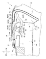
- FIG. 6 shows the console box 2 according to the second embodiment from that of the first embodiment only in the shape of the pair of second rails 43 of the guide portion 40, and the other configuration is the same as that of the first embodiment. . Therefore, the detailed description about the member and structure which are common in Embodiment 1 is abbreviate
- FIG. 6 shows the opening / closing operation of the movable lid 22 guided and moved by the first and second rails 41 and 43, and the accessory tray 8, the lock mechanism 50, the arm 60, etc. are omitted. Yes.
- the pair of second rails 43 according to the second embodiment includes an inclined portion 43a that is inclined downward from the front end to the rear side, and a guide portion 43b that continuously extends from the end of the inclined portion 43a. Different from that of Form 1.
- the guide portion 43b according to the second embodiment has no straight portion 42b1 as in the first embodiment, and is formed in a shape combining only a plurality of arcs having different curvatures.
- the guide portion 43b is formed so that the curvature gradually decreases as the distance from the end of the inclined portion 43a increases.
- the guide part 43b is formed in the shape which combined only the circular arc in which the center of curvature of an arc is located in the front side of the guide part 43b. Therefore, the front half portion of the guide portion 43b is shifted to the front side because there is no straight portion in the front half portion (upper half portion) of the guide portion 43b. Further, the distance that the second shaft 32 that slides on the guide portion 43b moves from the fully closed position to the fully open position of the movable lid 22 is shorter than that in the first embodiment.
- an operator such as a passenger opens and closes the movable lid 22 as in the first embodiment.
- the movable lid 22 supported by the first shaft 31 that slides on the first rail 41 and the second shaft 32 that slides on the second rail 43 slides and rotates. Move to draw a movement trajectory as shown in FIG.
- the second shaft 32 that slides on each second rail 43 is moved by the shortest route from the fully closed position of the movable lid 22 to the fully open position because the guide portion 43b is shorter than that of the first embodiment. To do.
- the first to third lock holes 51a, 51b, 51c of the lock mechanism 50 are provided in the same manner as in the first embodiment, and the movable lid 22 is in the fully closed position (see FIG. 2) and the half open position (see FIG. 4). ) And the fully open position (see FIG. 5). Therefore, the movable lid 22 is stored in the lid storage space 18 in a locked state at the fully open position, as in the first embodiment.
- the console box 2 of the second embodiment configured as described above has the same effects as the console box 1 of the first embodiment. Furthermore, according to the console box 2 of the second embodiment, since the guide portion 43b of the second rail 43 is formed in a shape combining only a plurality of arcs having different curvatures, the front half portion of the guide portion 43b is located on the front side. Can be sent to. Therefore, since the rear wall 13 of the box body 10 can be moved to the front side as much as it is moved to the front side, the length of the box body 10 in the front-rear direction can be shortened. Moreover, the volume of the lid storage space 18 can be reduced, and the movable lid 22 can be stored more compactly. Further, since the guide portions 43b of the second rails 43 are shorter than those of the first embodiment, the movable lid 22 can be moved from the fully closed position to the fully open position by the shortest route. 22 quick opening and closing operations can be performed.
- first rail 41 and the second rails 42 and 43 in the above embodiment are formed by long grooves extending in the side wall 12, but when the side wall 12 is constituted by a thin panel or the like, You may form by providing the slit-shaped long hole which penetrates a panel etc. in the thickness direction.
- the inclined portions 42a and 43a of the second rails 42 and 43 of the above embodiment are formed in a straight shape, but a plurality of arcs having different straight shapes and curvatures such as the curved portion 42b2 and the guide portion 43b are used. You may make it form in the shape which combined.
- the lock mechanism 50 that locks the movable lid 22 in the fully open position is configured to be locked by fitting the first shaft 31 and the third lock hole 51c.
- a conventionally known technique such as a heart cam mechanism may be employed.
- the second urging member 62 that urges the pair of arms 60 from the fully open position of the movable lid 22 toward the fully closed position is provided.
- electric power such as an electric device may be used.
Landscapes
- Engineering & Computer Science (AREA)
- Mechanical Engineering (AREA)
- Transportation (AREA)
- Aviation & Aerospace Engineering (AREA)
- Vehicle Step Arrangements And Article Storage (AREA)
- Passenger Equipment (AREA)
Priority Applications (2)
| Application Number | Priority Date | Filing Date | Title |
|---|---|---|---|
| US17/048,145 US11766970B2 (en) | 2018-04-17 | 2019-04-16 | Storage box |
| CN201980026604.4A CN112055669B (zh) | 2018-04-17 | 2019-04-16 | 收纳箱 |
Applications Claiming Priority (2)
| Application Number | Priority Date | Filing Date | Title |
|---|---|---|---|
| JP2018-079242 | 2018-04-17 | ||
| JP2018079242A JP6848929B2 (ja) | 2018-04-17 | 2018-04-17 | 収納ボックス |
Publications (1)
| Publication Number | Publication Date |
|---|---|
| WO2019203214A1 true WO2019203214A1 (ja) | 2019-10-24 |
Family
ID=68239175
Family Applications (1)
| Application Number | Title | Priority Date | Filing Date |
|---|---|---|---|
| PCT/JP2019/016265 Ceased WO2019203214A1 (ja) | 2018-04-17 | 2019-04-16 | 収納ボックス |
Country Status (4)
| Country | Link |
|---|---|
| US (1) | US11766970B2 (https=) |
| JP (1) | JP6848929B2 (https=) |
| CN (1) | CN112055669B (https=) |
| WO (1) | WO2019203214A1 (https=) |
Cited By (1)
| Publication number | Priority date | Publication date | Assignee | Title |
|---|---|---|---|---|
| WO2021039450A1 (ja) * | 2019-08-29 | 2021-03-04 | 東京エレクトロン株式会社 | 検査装置の自己診断方法および検査装置 |
Families Citing this family (6)
| Publication number | Priority date | Publication date | Assignee | Title |
|---|---|---|---|---|
| JP6848929B2 (ja) * | 2018-04-17 | 2021-03-24 | 豊田合成株式会社 | 収納ボックス |
| DE102018206316B4 (de) * | 2018-04-24 | 2021-06-24 | Audi Ag | Abgedichtetes Staufach für ein Kraftfahrzeug und Kraftfahrzeug mit einem solchen Staufach |
| US11318892B2 (en) * | 2019-04-19 | 2022-05-03 | Shanghai Yanfeng Jinqiao Automotive Trim Systems Co. Ltd. | Vehicle interior component |
| CN115362304B (zh) * | 2020-03-23 | 2025-08-26 | 上海延锋金桥汽车饰件系统有限公司 | 车辆内部部件 |
| CN113844370A (zh) * | 2021-11-01 | 2021-12-28 | 沃柏模塑科技(苏州)有限公司 | 一种车辆储物装置 |
| CN116215389A (zh) * | 2023-03-30 | 2023-06-06 | 昆山金运新材料科技有限公司 | 智能车载中控置物箱 |
Citations (3)
| Publication number | Priority date | Publication date | Assignee | Title |
|---|---|---|---|---|
| JP2005319901A (ja) * | 2004-05-10 | 2005-11-17 | Nifco Inc | 分割蓋機構、および、センターコンソールボックス |
| JP2009248793A (ja) * | 2008-04-08 | 2009-10-29 | Nifco Inc | 蓋体の開閉機構及び車両用小物入れ |
| JP2010137765A (ja) * | 2008-12-12 | 2010-06-24 | Nippon Plast Co Ltd | 蓋可動装置 |
Family Cites Families (23)
| Publication number | Priority date | Publication date | Assignee | Title |
|---|---|---|---|---|
| US3022107A (en) * | 1960-10-31 | 1962-02-20 | Gen Motors Corp | Vehicle closure |
| JP2789223B2 (ja) * | 1989-06-05 | 1998-08-20 | 株式会社ニフコ | 蓋体の開閉装置 |
| JPH1191446A (ja) * | 1997-09-24 | 1999-04-06 | Kanto Auto Works Ltd | コンソ−ルボックス |
| JP3293063B2 (ja) * | 1997-12-08 | 2002-06-17 | カシオ計算機株式会社 | 蓋体の開閉構造 |
| JP2001158305A (ja) * | 1999-12-03 | 2001-06-12 | Kojima Press Co Ltd | 車両用内装部材 |
| JP4131202B2 (ja) * | 2002-07-11 | 2008-08-13 | 豊田合成株式会社 | コンソールボックス |
| JP4241532B2 (ja) | 2004-07-16 | 2009-03-18 | 豊田合成株式会社 | 収納ボックスの開閉機構 |
| JP4912183B2 (ja) * | 2007-02-28 | 2012-04-11 | 株式会社ニフコ | 可動体の動作制御装置及びコンソールボックス |
| JP5134388B2 (ja) * | 2008-02-14 | 2013-01-30 | 株式会社ニフコ | リッド装置 |
| JP4648965B2 (ja) * | 2008-08-02 | 2011-03-09 | 森六テクノロジー株式会社 | 収納ボックスの開閉機構 |
| JP5661350B2 (ja) * | 2009-08-27 | 2015-01-28 | 日本プラスト株式会社 | 乗り物用物入れ装置 |
| IN2015DN00297A (https=) * | 2012-07-13 | 2015-06-12 | Johnson Controls Tech Co | |
| US10077003B2 (en) * | 2012-07-13 | 2018-09-18 | Shanghai Yanfeng Jinqiao Automotive Trim Systems Co. Ltd. | Vehicle interior component |
| JP6080704B2 (ja) * | 2013-06-18 | 2017-02-15 | ミネベアミツミ株式会社 | 表示装置 |
| WO2015100254A1 (en) * | 2013-12-23 | 2015-07-02 | Johnson Controls Technology Company | Flexible interior trim component having a deployable retaining feature |
| WO2017200983A1 (en) * | 2016-05-17 | 2017-11-23 | Shanghai Yanfeng Jinqiao Automotive Trim Systems Co. Ltd | Console for vehicle interior |
| US10150397B2 (en) * | 2016-09-30 | 2018-12-11 | Nissan North America, Inc. | Vehicle storage structure |
| US10106092B2 (en) * | 2017-02-09 | 2018-10-23 | Ford Global Technologies, Llc | Expandable and reconfigurable console |
| KR102322363B1 (ko) * | 2017-02-20 | 2021-11-04 | 현대자동차주식회사 | 슬라이딩 암레스트 콘솔 개폐장치 |
| KR102052925B1 (ko) * | 2017-11-09 | 2019-12-11 | 주식회사 서연이화 | 차량용 컵홀더 장치의 커버 |
| JP6848929B2 (ja) * | 2018-04-17 | 2021-03-24 | 豊田合成株式会社 | 収納ボックス |
| JP7052581B2 (ja) * | 2018-06-13 | 2022-04-12 | 豊田合成株式会社 | 収容装置 |
| US11904811B2 (en) * | 2021-03-01 | 2024-02-20 | Ford Global Technologies, Llc | Storage assembly for a vehicle |
-
2018
- 2018-04-17 JP JP2018079242A patent/JP6848929B2/ja active Active
-
2019
- 2019-04-16 CN CN201980026604.4A patent/CN112055669B/zh active Active
- 2019-04-16 WO PCT/JP2019/016265 patent/WO2019203214A1/ja not_active Ceased
- 2019-04-16 US US17/048,145 patent/US11766970B2/en active Active
Patent Citations (3)
| Publication number | Priority date | Publication date | Assignee | Title |
|---|---|---|---|---|
| JP2005319901A (ja) * | 2004-05-10 | 2005-11-17 | Nifco Inc | 分割蓋機構、および、センターコンソールボックス |
| JP2009248793A (ja) * | 2008-04-08 | 2009-10-29 | Nifco Inc | 蓋体の開閉機構及び車両用小物入れ |
| JP2010137765A (ja) * | 2008-12-12 | 2010-06-24 | Nippon Plast Co Ltd | 蓋可動装置 |
Cited By (1)
| Publication number | Priority date | Publication date | Assignee | Title |
|---|---|---|---|---|
| WO2021039450A1 (ja) * | 2019-08-29 | 2021-03-04 | 東京エレクトロン株式会社 | 検査装置の自己診断方法および検査装置 |
Also Published As
| Publication number | Publication date |
|---|---|
| CN112055669A (zh) | 2020-12-08 |
| CN112055669B (zh) | 2023-09-26 |
| JP2019182370A (ja) | 2019-10-24 |
| US20210146847A1 (en) | 2021-05-20 |
| JP6848929B2 (ja) | 2021-03-24 |
| US11766970B2 (en) | 2023-09-26 |
Similar Documents
| Publication | Publication Date | Title |
|---|---|---|
| WO2019203214A1 (ja) | 収納ボックス | |
| JP2019182370A5 (https=) | ||
| JP4648965B2 (ja) | 収納ボックスの開閉機構 | |
| JP4131202B2 (ja) | コンソールボックス | |
| JP3953770B2 (ja) | 開閉部材の制動機構、これを備えた容器ホルダー及び自動車用扉 | |
| CN102227338A (zh) | 汽车杂物箱 | |
| KR101417535B1 (ko) | 자동차의 멀티 박스 | |
| WO2021070845A1 (ja) | 車両用物品収納構造 | |
| CN103703205A (zh) | 盖开闭机构以及收纳装置 | |
| WO2012161034A1 (ja) | カップホルダー | |
| JP2008044579A (ja) | グローブボックスの開閉構造 | |
| JP2008149816A (ja) | コンソールボックスの蓋体の開閉構造 | |
| JP2003161073A (ja) | 蓋体の開閉機構 | |
| JP2017202732A (ja) | オーバーヘッドコンソール装置 | |
| JP2010254233A (ja) | コンソールボックス | |
| JP2009184498A (ja) | 車内用物入れ | |
| JP2008080828A (ja) | コンソールボックス構造 | |
| JP4650369B2 (ja) | 蓋付き装置 | |
| JP4415262B2 (ja) | 車両用収納装置 | |
| JP2008155822A (ja) | スライドドア装置 | |
| JP4505308B2 (ja) | グローブボックス | |
| KR101126903B1 (ko) | 차량 내 수납 공간 | |
| JP7565242B2 (ja) | 車両用収納装置 | |
| JP2008162382A (ja) | スライドドア装置 | |
| JP2009149115A (ja) | 車両用オーバーヘッドコンソール装置 |
Legal Events
| Date | Code | Title | Description |
|---|---|---|---|
| 121 | Ep: the epo has been informed by wipo that ep was designated in this application |
Ref document number: 19789083 Country of ref document: EP Kind code of ref document: A1 |
|
| NENP | Non-entry into the national phase |
Ref country code: DE |
|
| 122 | Ep: pct application non-entry in european phase |
Ref document number: 19789083 Country of ref document: EP Kind code of ref document: A1 |