WO2019192531A1 - 通信方法、通信装置和系统 - Google Patents
通信方法、通信装置和系统 Download PDFInfo
- Publication number
- WO2019192531A1 WO2019192531A1 PCT/CN2019/081306 CN2019081306W WO2019192531A1 WO 2019192531 A1 WO2019192531 A1 WO 2019192531A1 CN 2019081306 W CN2019081306 W CN 2019081306W WO 2019192531 A1 WO2019192531 A1 WO 2019192531A1
- Authority
- WO
- WIPO (PCT)
- Prior art keywords
- resource
- reference signal
- demodulation reference
- downlink
- transmitting
- Prior art date
- Legal status (The legal status is an assumption and is not a legal conclusion. Google has not performed a legal analysis and makes no representation as to the accuracy of the status listed.)
- Ceased
Links
Images




Classifications
-
- H—ELECTRICITY
- H04—ELECTRIC COMMUNICATION TECHNIQUE
- H04L—TRANSMISSION OF DIGITAL INFORMATION, e.g. TELEGRAPHIC COMMUNICATION
- H04L5/00—Arrangements affording multiple use of the transmission path
-
- H—ELECTRICITY
- H04—ELECTRIC COMMUNICATION TECHNIQUE
- H04L—TRANSMISSION OF DIGITAL INFORMATION, e.g. TELEGRAPHIC COMMUNICATION
- H04L5/00—Arrangements affording multiple use of the transmission path
- H04L5/003—Arrangements for allocating sub-channels of the transmission path
- H04L5/0048—Allocation of pilot signals, i.e. of signals known to the receiver
-
- H—ELECTRICITY
- H04—ELECTRIC COMMUNICATION TECHNIQUE
- H04W—WIRELESS COMMUNICATION NETWORKS
- H04W72/00—Local resource management
- H04W72/04—Wireless resource allocation
-
- H—ELECTRICITY
- H04—ELECTRIC COMMUNICATION TECHNIQUE
- H04W—WIRELESS COMMUNICATION NETWORKS
- H04W72/00—Local resource management
- H04W72/04—Wireless resource allocation
- H04W72/044—Wireless resource allocation based on the type of the allocated resource
- H04W72/0446—Resources in time domain, e.g. slots or frames
-
- H—ELECTRICITY
- H04—ELECTRIC COMMUNICATION TECHNIQUE
- H04W—WIRELESS COMMUNICATION NETWORKS
- H04W72/00—Local resource management
- H04W72/04—Wireless resource allocation
- H04W72/044—Wireless resource allocation based on the type of the allocated resource
- H04W72/0453—Resources in frequency domain, e.g. a carrier in FDMA
Definitions
- the present application relates to the field of wireless communications and, more particularly, to a communication method, communication apparatus and system.
- the demodulation reference signal can be used for demodulation of data during data transmission. For example, it is transmitted together with the downlink data in the physical downlink shared channel for demodulation of the downlink data, or is transmitted together with the uplink data in the physical uplink shared channel for demodulation of the uplink data.
- the receiving end device it is necessary to know the position of the demodulation reference signal transmitted by the transmitting end device in advance, so that the demodulation reference signal can be received at the position, thereby performing data demodulation.
- a synchronization signal/physical broadcast channel block (synchronization signal/) is defined.
- the SS/PBCH block and the physical downlink shared channel may be configured on the same frequency domain resource.
- resource conflict may occur, and the demodulation reference signal may not be correctly received, which may affect the receiving performance of the downlink data.
- the present application provides a communication method, communication apparatus and system for demodulating the correct reception of a reference signal, thereby improving data transmission performance.
- a communication method comprising:
- the downlink pre-demodulation reference signal is transmitted based on the second resource.
- the network device and the terminal device may determine, according to the same rule, the resource used for transmitting the downlink demodulation reference signal according to the location of the first resource of the SS/PBCH block in the time domain, so that the network device and the terminal device may The downlink pre-demodulation reference signal is transmitted on the same resource.
- the downlink pre-demodulation reference signal and the resource overlap of the SS/PBCH block can be avoided, thereby facilitating the terminal device to correctly receive the downlink demodulation reference signal to demodulate the downlink data. Therefore, it is advantageous to improve the reception performance of downlink data and improve the reliability of data transmission.
- a communication method including:
- the network device and the terminal device may determine, according to the same rule, the resource used for transmitting the downlink demodulation reference signal according to the location of the first resource of the SS/PBCH block in the time domain, so that the network device and the terminal device may The downlink pre-demodulation reference signal is transmitted on the same resource.
- the downlink pre-demodulation reference signal and the resource overlap of the SS/PBCH block can be avoided, thereby facilitating the terminal device to correctly receive the downlink demodulation reference signal to demodulate the downlink data. Therefore, it is advantageous to improve the receiving performance of downlink data and improve the reliability of data transmission.
- the method further includes:
- the third resource is determined according to the downlink pre-demodulation reference signal mapping type A.
- the downlink pre-demodulation reference signal mapping type A is a mapping manner of a downlink demodulation reference signal defined in the NR protocol, and the resource determined according to the mapping type A (ie, the third resource) can be used to transmit the downlink pre-position. Demodulate the reference signal.
- resource overlap may occur between the third resource and the first resource, and the method provided by the present application can determine a resource for transmitting a downlink pre-demodulation reference signal based on the first resource (ie, The second resource is such that the second resource does not overlap with the first resource, thereby avoiding the problem of resource overlap and facilitating correct reception of the downlink demodulation reference signal.
- the third resource can be understood as a predefined resource for transmitting the downlink pre-demodulation reference signal
- the second resource can be understood as the resource of the final downlink pre-demodulation reference signal used for transmission.
- the first resource and the third resource overlap in the frequency domain, and the first resource and the third resource partially overlap or overlap in the time domain.
- the second resource used for transmitting the downlink pre-demodulation reference signal including:
- the downlink pre-demodulation reference signal is still transmitted in the frequency band in which the first resource is located, that is, the physical downlink shared channel is still transmitted in the frequency band in which the first resource is located.
- the second resource for transmitting the downlink pre-demodulation reference signal does not overlap with the first resource in the time domain, thereby facilitating correct reception of the downlink demodulation reference signal.
- determining, according to the location of the first resource occupied by the SS/PBCH block in the time domain, the location of the second resource used for transmitting the downlink pre-demodulation reference signal in the time domain including:
- the terminal device and the network device can determine the second resource for transmitting the downlink pre-demodulation reference signal based on the same rule, which is simple and convenient, and is easy to implement.
- determining, according to the location of the first resource occupied by the SS/PBCH block in the time domain, the location of the second resource used for transmitting the downlink pre-demodulation reference signal in the time domain including:
- the first mapping relationship indicates a one-to-one correspondence between the mapping manner of the at least one SS/PBCH block and the time domain position mapable by the at least one downlink pre-demodulation reference signal, and the mapping manner of the SS/PBCH block is used to determine the SS.
- the terminal device and the network device may determine, according to the first mapping relationship saved in advance, the location of the second resource used for transmitting the downlink pre-demodulation reference signal in the time domain, and only need to know the mapping manner of the SS/PBCH block.
- the mapping relationship determines the location of the second resource in the time domain, which is low in complexity for the terminal device.
- determining, according to the location of the first resource occupied by the SS/PBCH block in the time domain, the location of the second resource used for transmitting the downlink pre-demodulation reference signal in the time domain including:
- the network device determines the fourth resource as the second resource.
- the terminal device and the network device may determine the fourth resource as the second resource if the fourth resource does not overlap with the first resource in the time domain.
- the terminal device only needs to determine whether to use the fourth resource as the second resource according to the location of the fourth resource indicated by the network device in the time domain.
- the above methods can be used in combination.
- the first resource and the third resource overlap in the frequency domain, and the first resource and the third resource partially overlap or overlap in the time domain.
- the second resource used for transmitting the downlink demodulation reference signal including:
- the downlink pre-demodulation reference signal is not transmitted in the frequency band in which the first resource is located, that is, the physical downlink shared channel is not transmitted in the frequency band in which the first resource is located. Therefore, the first resource and the second resource for transmitting the downlink pre-demodulation reference signal do not overlap in the frequency domain, and the time domain resource corresponding to the third resource determined by the mapping mode A can still be used in the time domain. .
- This implementation can be understood as rate matching at the RB level. In this way, it is also possible to prevent the second resource for transmitting the downlink pre-demodulation reference signal from overlapping with the first resource in the time domain, thereby facilitating correct reception of the downlink demodulation reference signal.
- a communication method including:
- An uplink demodulation reference signal is transmitted on the resource.
- the terminal device and the network device may determine the mapping manner of the uplink demodulation reference signal based on the same determination condition, so that the uplink demodulation reference signal can be transmitted on the same resource. Therefore, the network device can correctly receive the uplink demodulation reference signal to demodulate the uplink data, which is beneficial to improving the receiving performance of the uplink data and improving the reliability of the data transmission.
- the terminal device can consider to communicate with the network device in the DTDD mode when receiving the SFI, and the DTDD mode is beneficial to improve the frequency utilization. Since the downlink demodulation reference signal is mapped by the mapping method A in the normal case, if the uplink demodulation reference signal is also used in the mapping mode A for resource mapping in the DTDD mode, the uplink and downlink demodulation reference can be made. The probability that the signal will align in the time domain increases. In DTDD mode, the inter-cell interference is a major factor affecting the signal quality, and the uplink and downlink demodulation reference signals are aligned in the time domain to facilitate the conversion of the anisotropic interference into the same-direction interference. Existing interference estimation and cancellation techniques reduce the impact on data transmission.
- the embodiment of the present application considers the mapping manner of the uplink demodulation reference signal in the DTDD mode as the mapping type A, which is beneficial to realize the symmetric design of the uplink and downlink, thereby facilitating interference estimation and elimination, and enabling data transmission in the DTDD mode.
- the quality is improved.
- a communication method including:
- An uplink demodulation reference signal is transmitted on the resource.
- the terminal device and the network device may determine the mapping manner of the uplink demodulation reference signal based on the same determination condition, so that the uplink demodulation reference signal can be transmitted on the same resource. Therefore, the network device can correctly receive the uplink demodulation reference signal to demodulate the uplink data, which is beneficial to improving the receiving performance of the uplink data and improving the reliability of the data transmission.
- the network device and the terminal device may pre-arrange the resource mapping based on the first mapping manner when the terminal device receives the SFI from the network device and the waveform of the uplink transmission is multi-carrier.
- the judgment condition for using the first mapping mode is increased, and in the case where the SFI is received and multi-carrier modulation is adopted, the transmission uplink demodulation is determined by the first mapping mode.
- the resource of the reference signal Due to the multi-carrier modulation technology commonly used in downlink transmission, multi-carrier modulation technology is also used in the uplink to provide a basis for the symmetric design of uplink and downlink pilots, so that the probability of uplink and downlink demodulation reference signals increases in the time domain. Therefore, it is also more conducive to interference estimation and elimination, so that the quality of DTDD mode data transmission is improved. At the same time, the utilization of spectrum resources can be improved by adopting the DTDD mode.
- the method further includes:
- the resource indication information is carried in the downlink control information.
- the terminal device may determine whether to use the first mapping manner to determine a resource for transmitting the uplink demodulation reference signal, based on whether the resource indication information is received, or whether the resource indication information is obtained in the downlink control information.
- a communication method including:
- An uplink demodulation reference signal is received on the resource.
- the terminal device and the network device may determine the mapping manner of the uplink demodulation reference signal based on the same determination condition, so that the uplink demodulation reference signal can be transmitted on the same resource. Therefore, the network device can correctly receive the uplink demodulation reference signal to demodulate the uplink data, which is beneficial to improving the receiving performance of the uplink data and improving the reliability of the data transmission.
- the terminal device can be considered to communicate with the network device by using the DTDD mode when receiving the SFI, and the DTDD mode is beneficial to improving the utilization of the spectrum resources.
- the downlink demodulation reference signal is mapped by the mapping method A in the normal case, if the uplink demodulation reference signal is also used in the mapping mode A for resource mapping in the DTDD mode, the uplink and downlink demodulation reference can be made. The probability that the signal will align in the time domain increases. In DTDD mode, the inter-cell interference is a major factor affecting the signal quality, and the uplink and downlink demodulation reference signals are aligned in the time domain to facilitate the conversion of the anisotropic interference into the same-direction interference.
- the embodiment of the present application considers the mapping manner of the uplink demodulation reference signal in the DTDD mode as the mapping type A, which is beneficial to realize the symmetric design of the uplink and downlink, thereby facilitating interference estimation and elimination, and enabling data transmission in the DTDD mode. The quality is improved.
- a communication method including:
- An uplink demodulation reference signal is received on the resource.
- the terminal device and the network device may determine the mapping manner of the uplink demodulation reference signal based on the same determination condition, so that the uplink demodulation reference signal can be transmitted on the same resource. Therefore, the network device can correctly receive the uplink demodulation reference signal to demodulate the uplink data, which is beneficial to improving the receiving performance of the uplink data and improving the reliability of the data transmission.
- the network device and the terminal device may pre-arrange the resource mapping based on the first mapping manner when the terminal device receives the SFI from the network device and the waveform of the uplink transmission is multi-carrier.
- the judgment condition for using the first mapping mode is increased, and in the case where the SFI is received and multi-carrier modulation is adopted, the transmission uplink demodulation is determined by the first mapping mode.
- the resource of the reference signal Due to the multi-carrier modulation technology commonly used in downlink transmission, multi-carrier modulation technology is also used in the uplink to provide a basis for the symmetric design of uplink and downlink pilots, so that the probability of uplink and downlink demodulation reference signals increases in the time domain. Therefore, it is also more conducive to interference estimation and elimination, so that the quality of DTDD mode data transmission is improved. At the same time, the utilization of spectrum resources can be improved by adopting the DTDD mode.
- the method further includes:
- the resource indication information is sent, and the resource indication information indicates a transmission resource that carries downlink control information of the SFI.
- the resource indication information is carried in the downlink control information.
- the terminal device may determine whether to use the first mapping manner to determine a resource for transmitting the uplink demodulation reference signal, based on whether the resource indication information is received, or whether the resource indication information is obtained in the downlink control information.
- the first mapping mode is the mapping type A of the uplink demodulation reference signal.
- the second mapping mode is a mapping type B of the uplink demodulation reference signal.
- a communication device having the function of implementing a network device in the method design of the first, fifth or sixth aspect described above. These functions can be implemented in hardware or in software by executing the corresponding software.
- the hardware or software includes one or more units corresponding to the functions described above.
- a communication device having the function of implementing a terminal device in the method design of the second, third or fourth aspect described above. These functions can be implemented in hardware or in software by executing the corresponding software.
- the hardware or software includes one or more units corresponding to the functions described above.
- a communication device may be a network device in the foregoing method embodiment or a chip configured in the network device.
- the device has the function of implementing the method of the first, fifth or sixth aspect described above. This function can be implemented in hardware or in hardware by executing the corresponding software.
- the hardware or software includes one or more modules corresponding to the functions described above.
- the apparatus includes a processing unit and a communication unit, and optionally, the apparatus may further include a storage unit.
- the processing unit may complete the receiving or transmitting of information through the communication unit, and the processing unit may process the information such that the apparatus implements the method of the first, fifth or sixth aspect described above.
- the processing unit can be, for example, a processor
- the communication unit can be, for example, a transceiver, the transceiver comprising a radio frequency circuit
- the storage unit can be, for example, Is the memory.
- the network device includes a storage unit, the storage unit is configured to store a computer execution instruction, the processing unit is coupled to the storage unit, and the processing unit executes a computer execution instruction stored by the storage unit to cause the network device to perform the first The method of the fifth or sixth aspect.
- the processing unit may be, for example, a processor, which may be, for example, an input/output interface, a pin or a circuit, or the like.
- the processing unit may execute computer-executable instructions stored by the storage unit to cause a chip within the network device to perform the method of the first, fifth or sixth aspects above.
- the storage unit is a storage unit in the chip, such as a register, a cache, etc., and the storage unit may also be a storage unit outside the chip in the network device, such as a read-only memory (read-only memory, ROM) or other types of static storage devices, random access memory (RAM), etc. that can store static information and instructions.
- a communication device which may be a terminal device in the foregoing method embodiment or a chip configured in the terminal device.
- the device has the function of implementing the method of the second, third or fourth aspect described above. This function can be implemented in hardware or in hardware by executing the corresponding software.
- the hardware or software includes one or more modules corresponding to the functions described above.
- the apparatus includes a processing unit and a communication unit, and optionally, the apparatus may further include a storage unit.
- the processing unit may complete receiving or transmitting information through the communication unit, and the processing unit may process the information to enable the device to implement the method of the second, third or fourth aspect.
- the device is a terminal device.
- the terminal device comprises: a processing unit and a communication unit, the processing unit being, for example, a processor, the communication unit being, for example, a transceiver, the transceiver comprising a radio frequency circuit, optionally the terminal device further comprising a storage unit, the storage
- the unit can be, for example, a memory.
- the storage unit is configured to store a computer execution instruction
- the processing unit is connected to the storage unit, and the processing unit executes a computer execution instruction stored by the storage unit, so that the terminal device performs the second The method of the third or fourth aspect.
- the device is a chip within the terminal device.
- the chip comprises a processing unit and a communication unit, which may for example be a processor, which may for example be an input/output interface, a pin or a circuit or the like.
- the processing unit may execute computer execution instructions stored by the storage unit to cause the chip within the terminal device to perform the wireless communication method of any of the above aspects.
- the storage unit is a storage unit in the chip, such as a register, a cache, etc., and the storage unit may also be a storage unit located outside the chip in the terminal device, such as a read-only memory or may store static information and Other types of static storage devices, random access memory, etc.
- the processor mentioned in any of the above may be a general central processing unit (CPU), a microprocessor, an application-specific integrated circuit (ASIC), or one or more An integrated circuit for controlling program execution of the method of the second aspect above.
- CPU central processing unit
- ASIC application-specific integrated circuit
- a system comprising the above terminal device and a network device.
- a computer storage medium storing a program for implementing the methods of the above aspects.
- the program When the program is run in the device, the device is caused to perform the methods of the various aspects described above.
- a computer program product comprising a program or instruction that, when executed, causes the methods of the above aspects to be performed.
- FIG. 1 is a schematic diagram of a communication system suitable for use in an embodiment of the present application
- 2 is a schematic diagram of symbols occupied by SS/PBCH blocks of the case B candidate and symbols occupied by the downlink demodulation reference signal;
- FIG. 3 is a schematic flowchart of a communication method provided by an embodiment of the present application.
- FIG. 6 is a schematic diagram showing symbol length relationships corresponding to different subcarrier spacings in case B and case D;
- FIG. 7 is a schematic diagram of a pilot pattern of a demodulation reference signal in case B and case D;
- Figure 8 is another schematic diagram of a pilot pattern of a demodulation reference signal in Case B and Case D;
- FIG. 9 is another schematic diagram of a pilot pattern of a demodulation reference signal in Case A and Case C;
- Figure 10 is a schematic diagram of a pilot pattern of a demodulation reference signal
- FIG. 11 is a schematic flowchart of a communication method according to another embodiment of the present application.
- FIG. 12 is a schematic flowchart of a communication method according to another embodiment of the present application.
- FIG. 13 is a schematic block diagram of a communication apparatus according to an embodiment of the present application.
- FIG. 14 is another schematic block diagram of a communication apparatus according to an embodiment of the present application.
- FIG. 15 is a schematic structural diagram of a network device according to an embodiment of the present application.
- FIG. 16 is a schematic structural diagram of a terminal device according to an embodiment of the present application.
- the technical solution of the embodiment of the present application can be applied to various communication systems, such as, but not limited to, a Narrow Band-Internet of Things (NB-IoT), and a Global System of Mobile communication (GSM) system.
- Code Division Multiple Access (CDMA) system Wideband Code Division Multiple Access (WCDMA) system, General Packet Radio Service (GPRS), Long Term Evolution (Long Term Evolution) , LTE) system, LTE Frequency Division Duplex (FDD) system, LTE Time Division Duplex (TDD), Universal Mobile Telecommunication System (UMTS), Global Interconnected Microwave Access ( Worldwide Interoperability for Microwave Access, WiMAX) communication system, future 5th Generation (5G) system or new radio access technology (NR).
- CDMA Code Division Multiple Access
- WCDMA Wideband Code Division Multiple Access
- GPRS General Packet Radio Service
- LTE Long Term Evolution
- LTE Long Term Evolution Frequency Division Duplex
- TDD Time Division Duplex
- UMTS Universal Mobile Telecommunication System
- FIG. 1 is a schematic diagram of a communication system 100 suitable for use in a communication method of an embodiment of the present application.
- the communication system 100 can include at least one network device (e.g., network device 102 shown in the figures) and at least one (e.g., terminal device 104 shown in the figures), the network device 102 can be associated with the terminal Device 104 communicates.
- the communication system 100 may further include more network devices and/or more terminal devices, which is not limited in this application.
- the network device may be any device with a wireless transceiver function or a chip that can be disposed on the device.
- the device includes, but is not limited to, an evolved Node B (eNB), a Radio Network Controller (RNC), a Node B (NB), and a Base Station Controller (BSC).
- eNB evolved Node B
- RNC Radio Network Controller
- NB Node B
- BSC Base Station Controller
- BTS Base Transceiver Station
- home base station for example, Home evolved NodeB, or Home Node B, HNB
- BBU BaseBand Unit
- WIFI Wireless Fidelity
- Access point wireless relay node, wireless backhaul node, transmission point (TRP or transmission point, TP), etc.
- TRP or transmission point, TP transmission point
- AP can also be 5G, such as NR, gNB in the system Or, a transmission point (TRP or TP), one or a group of base stations (including multiple antenna panels) in the 5G system, or, alternatively, a network node constituting a gNB or a transmission point, such as a baseband unit (BBU) ), or, distributed unit (DU), etc.
- 5G such as NR, gNB in the system Or, a transmission point (TRP or TP), one or a group of base stations (including multiple antenna panels) in the 5G system, or, alternatively, a network node constituting a gNB or a transmission point, such as a baseband unit (BBU) ), or, distributed unit (DU), etc.
- BBU baseband unit
- DU distributed unit
- the gNB may include a centralized unit (CU) and a DU.
- the gNB may also include a radio unit (RU).
- the CU implements some functions of the gNB, and the DU implements some functions of the gNB.
- the CU implements radio resource control (RRC), the function of the packet data convergence protocol (PDCP) layer, and the DU implements the wireless chain.
- RRC radio resource control
- PDCP packet data convergence protocol
- the DU implements the wireless chain.
- the functions of the radio link control (RLC), the media access control (MAC), and the physical (PHY) layer Since the information of the RRC layer eventually becomes information of the PHY layer or is transformed by the information of the PHY layer, in this architecture, higher layer signaling, such as RRC layer signaling, can also be considered to be sent by the DU.
- the network device can be a CU node, or a DU node, or a device including a CU node and a DU node.
- the CU may be divided into network devices in the access network RAN, and the CU may be divided into network devices in the core network CN, which is not limited herein.
- a terminal device may also be called a user equipment (UE), an access terminal, a subscriber unit, a subscriber station, a mobile station, a mobile station, a remote station, a remote terminal, a mobile device, a user terminal, a terminal, a wireless communication device, and a user.
- Agent or user device may be a mobile phone, a tablet, a computer with a wireless transceiver function, a virtual reality (VR) terminal device, and an augmented reality (AR) terminal.
- VR virtual reality
- AR augmented reality
- the embodiment of the present application does not limit the application scenario.
- the foregoing terminal device and a chip that can be disposed in the foregoing terminal device are collectively referred to as a terminal device.
- network device 102 can communicate with a plurality of terminal devices (e.g., including terminal device 104 shown in the figures).
- the terminal device 104 can also communicate with a plurality of network devices (e.g., including the network device 102 shown in the figures).
- network device 102 shown in the figures.
- the examples are only for ease of understanding and are not shown.
- Resource element or resource element.
- One symbol can be corresponding to the time domain, and one subcarrier can be corresponding to the frequency domain.
- the RE may be an example of a resource unit.
- Resource block an RB occupies in the frequency domain Contiguous subcarriers and occupying in the time domain Continuous symbols. among them, Both are positive integers. For example, in the LTE protocol, Can be equal to 12, Can be equal to 7; in the NR protocol, Can be equal to 12, Can be equal to 14. In the embodiment of the present application, the RB may be another example of the resource unit.
- the embodiment of the present application does not limit the length of time of one symbol.
- the length of one symbol can vary for different subcarrier spacing.
- the symbols may include uplink symbols and downlink symbols.
- the uplink symbols may be referred to as Single Carrier-Frequency Division Multiple Access (SC-FDMA) symbols or Orthogonal Frequency Division Multiple Access (Orthogonal).
- Resource unit A unit of measure that can be used as a resource in the time-frequency domain.
- the resource unit may include, for example, an RB, a resource block group (RB group) composed of one or more RBs, one or more RB pairs, half RBs, and 1/4.
- RB, RE group composed of one or more REs, and the like.
- the RB pair is composed of 12 consecutive subcarriers in the frequency domain and one subframe in the time domain.
- Time slot In NR, the time slot is the minimum scheduling unit of time.
- the format of a time slot is 14 OFDM symbols, and the CP of each OFDM symbol is a normal CP; the format of one time slot is 12 OFDM symbols, and the CP of each OFDM symbol is an extended CP; The format is 7 OFDM symbols, and the CP of each OFDM symbol is a normal CP.
- the OFDM symbols in one slot can be used for uplink transmission; they can all be used for downlink transmission; some can be used for downlink transmission, some for uplink transmission, and some for reservation. It should be understood that the above examples are merely illustrative and should not be construed as limiting.
- the slot format is not limited to the above example for system forward compatibility considerations.
- Time division duplexing A duplex communication technique of a communication system for separating received and transmitted channels, that is, uplink and downlink.
- the uplink and downlink use the same frequency channel, and the uplink and downlink are distinguished by different time slots of the carrier.
- TDD has seven configurations.
- a frame has 10 subframes. If D is used to represent the downlink subframe and U is the uplink subframe, in each configuration, the order of D and U is fixed.
- the TDD configuration can be semi-statically configured or statically configured.
- the time slot is the schedulable minimum time unit, and the TDD has a plurality of different time slot ratios, and the time slot ratio can be fixed or dynamically changed.
- DTDD Dynamic TDD
- the ratio of different slot types in each frame can be dynamically changed, and each sub-frame varies with the sub-carrier spacing.
- the number of slots included is also different.
- a time slot may be a pure uplink time slot, a pure downlink time slot, an uplink dominated time slot, or a downlink dominated time slot.
- the symbols in the pure uplink time slot are all used as uplink symbols; the symbols in the pure downlink time slots are all downlink symbols; the number of uplink symbols in the uplink-based time slot is greater than the number of downlink symbols; the downlink-based time slot The number of mid-downlink symbols is greater than the number of uplink symbols; in addition, a guard band may be disposed between the uplink and downlink symbols.
- the demodulation reference signal may be a DMRS (demodulation reference signal) in the LTE protocol or the NR protocol, or may be other reference signals defined in future protocols for implementing the same function.
- a DMRS may be carried in a physical shared channel with a data signal for demodulating a data signal carried in a physical shared channel. For example, it is transmitted together with downlink data in a physical downlink share channel (PDSCH), or is transmitted together with uplink data in a physical uplink share channel (PUSCH).
- PDSCH physical downlink share channel
- PUSCH physical uplink share channel
- the demodulation reference signal may include a downlink demodulation reference signal transmitted through the physical downlink shared channel and an uplink demodulation reference signal transmitted through the physical uplink shared channel.
- the mapping manner of the demodulation reference signal in the time domain may include a first mapping manner and a second mapping manner, where the first mapping manner may be mapping type A (mapping type A) in the NR protocol, and the second mapping manner may be Mapping type A in the NR protocol.
- the mapping manner of the demodulation reference signal may be indicated by higher layer signaling, for example, radio resource control (RRC) signaling.
- RRC radio resource control
- the time domain position of the demodulation reference signal is defined relative to the start position of the time slot, and the symbol position l0 of the first demodulation reference signal in one time slot (ie, the pre-demodulation reference signal)
- the downlink demodulation reference signal may use the mapping type B for resource mapping, and in other cases, the mapping type A is used. In the present application, the case where the resource is determined by the mapping type B is not considered for the time being.
- the demodulation reference signal may include a pre-demodulation reference signal and an additional demodulation reference signal.
- the front-located demodulation reference signal may be referred to as a first demodulation reference signal, occupying one symbol or multiple symbols in the time domain, and if multiple symbols are occupied, the multiple symbols Continuous in the time domain.
- the demodulation reference signal generated by the same sequence after the pre-demodulation reference signal is an additional reference reference signal.
- the additional demodulation reference signal may be one or more symbols after the symbol occupied by the first demodulation reference signal, and the last of the symbols occupied by the pre-demodulation reference signal and the symbol occupied by the additional demodulation reference signal The first symbol is not continuous.
- the additional demodulation reference signal can be configured with resources through higher layer signaling, such as RRC signaling.
- the additional demodulation reference signal is an optional demodulation reference signal.
- one SS/PBCH block can be composed of 4 OFDM symbols.
- one SS/PBCH block can be composed of 240 consecutive subcarriers, that is, 20 consecutive RBs. .
- An SS/PBCH block can be understood as a piece of resources for transmitting a synchronization signal (SS) and/or a PBCH.
- the network device may transmit the PBCH and the synchronization signal on the resource, or may only transmit the PBCH or only the synchronization signal within the resource.
- the synchronization signal may include a primary synchronization signal (PSS) and a secondary synchronization signal (SSS).
- PSS primary synchronization signal
- SSS secondary synchronization signal
- an SS/PBCH block may also be referred to as a sync block (SSblock, SSB). This application does not limit this.
- SS/PBCH mapping in the time domain can include five possible mapping modes, corresponding to five cases in the NR protocol, namely, case A (case A) to case E (case E).
- the mapping mode of the SS/PBCH block can be determined according to the subcarrier spacing (SCS) of the currently used resource.
- SCS subcarrier spacing
- Case A The subcarrier spacing is 15 kilohertz (kHz).
- Case B (case B): The subcarrier spacing is 30 kHz.
- Case C (case C): The subcarrier spacing is 30kHZ.
- Case D (case D): The subcarrier spacing is 120 kHz.
- Case E The subcarrier spacing is 240 kHz.
- the resource in the case E subcarrier spacing is 240 kHz is not configured with a physical downlink shared channel, that is, not used for data transmission, that is, no demodulation reference signal is transmitted.
- resources with subcarrier spacing of 15 kHz, 30 kHz, and 120 kHz can be configured with physical downlink shared channels, that is, SS/PBCH blocks and data can be simultaneously transmitted, that is, SS/PBCH blocks and downlink solutions can be simultaneously transmitted. Adjust the reference signal.
- the candidate SS/PBCH block refers to an SS/PBCH block that can be configured for transmission, but does not necessarily transmit an SS/PBCH block.
- the symbols of the candidate SS/PBCH block refer to a set of resources configured to transmit SS/PBCH blocks, some or all of which may be used to transmit SS/PBCH blocks.
- the transmission resources of the SS/PBCH block and the resources of the downlink demodulation reference signal may collide.
- FIG. 2 is a schematic diagram of symbols occupied by candidate SS/PBCH blocks and symbols occupied by downlink demodulation reference signals in two consecutive time slots on the same subcarrier.
- FIG. 2 shows the mapping position of the candidate SS/PBCH block in the resource of the case B subcarrier spacing of 30 kHz in the time domain, and the shaded square in the figure indicates that the candidate SS/PBCH block is in the time domain. The location of the map.
- the candidate SS/PBCH blocks may be mapped to the symbolic sums numbered 4, 5, 6, 7, 8, 9, 10, 11 in slot #0 (slot#0).
- the downlink demodulation reference signal may be mapped to the symbols numbered 2 and/or 3 in slot #0 and the number 16 in slot #1 and / or 17 on the symbol. Therefore, the SS/PBCH block and the downlink demodulation reference signal exhibit resource collisions on the symbols of numbers 16 and /17 in slot #1.
- FIG. 2 is only for convenience of understanding.
- the SS/PBCH block uses other mapping methods (for example, Case A, Case C, and Case D) for resource mapping, it may also occur with the resources of the downlink demodulation reference signal. conflict. This may affect the reception of the downlink demodulation reference signal, resulting in a decrease in the reception performance of the downlink data.
- the present application provides a communication method capable of avoiding resource conflicts and improving reception performance.
- a resource unit includes symbols consecutively numbered from #0 in the time domain, and subcarriers included in the frequency domain are numbered starting from #0.
- the RB may include symbols #0 to #13 in the time domain, and may include subcarriers #0 to #11 in the frequency domain.
- i in the i-th (i ⁇ 0, and i is an integer) symbols (or subcarriers) in the following description corresponds to the number (index) of the symbol (or subcarrier), for example, 0.
- the symbol corresponds to the symbol numbered 0, that is, symbol #0.
- one resource unit may include symbols #1 to #14 in the time domain, and may include subcarriers #1 to #12 in the frequency domain.
- the downlink control information may be control signaling sent by using a physical downlink control channel, for example, may be DCI (downlink control information) in LTE or NR protocol, or may be controlled by physical downlink. Other signaling of the channel transmission that can be used to carry downlink control information.
- the physical downlink control channel may be a PDCCH (physical downlink control channel), an enhanced physical downlink control channel (EPDCCH) in the LTE or NR protocol, and other downlink channels having the foregoing functions defined as the network evolves. .
- resource overlap and “resource conflict” are used interchangeably, and those skilled in the art can understand that the meanings of the two are the same.
- resource overlap is a phenomenon seen on the time-frequency resource map
- resource conflict is the cause of the phenomenon of "resource overlap”. If the same RE is configured to transmit two or more signals, then the resource conflicts for the two or more signals on the RE occur.
- the resource for transmitting the SS/PBCH block and the downlink demodulation reference for transmitting has a resource overlap on this RE, that is, a resource conflict has occurred.
- pre-definition may be implemented by pre-storing corresponding codes, tables, or other manners that can be used to indicate related information in a device (for example, including a terminal device and a network device).
- a device for example, including a terminal device and a network device.
- the specific implementation manner is not limited.
- pre-definition can be defined in the protocol.
- “save” may refer to being stored in one or more memories.
- the one or more memories may be separate arrangements or integrated in an encoder or decoder, processor, or communication device.
- the one or more memories may also be partially provided separately, and some of them may be integrated in a decoder, a processor, or a communication device.
- the type of the memory may be any form of storage medium, which is not limited herein.
- the “protocol” in the embodiment of the present application may refer to a standard protocol in the communication field, and may include, for example, an LTE protocol, an NR protocol, and a related protocol applied in a future communication system, which is not limited in this application.
- the first, second, etc. are merely for facilitating the differentiation of different objects, and should not constitute any limitation to the present application. For example, distinguish between different resources, different mapping methods, and the like.
- “and/or” describes the association relationship of the associated object, indicating that there may be three relationships, for example, A and/or B, which may indicate that A exists separately, and A and B exist at the same time. There are three cases of B alone.
- the character "/" generally indicates that the contextual object is an "or” relationship.
- At least one means one or more; “at least one of A and B", similar to "A and/or B", describing the association of associated objects, indicating that there may be three relationships, for example, A and B. At least one of them may indicate that A exists separately, and A and B exist simultaneously, and B cases exist separately.
- the communication method provided by the present application is applicable to a wireless communication system, such as the wireless communication system 100 shown in FIG.
- the two communication devices in the wireless communication system have a wireless communication connection relationship, and one of the two communication devices may correspond to the terminal device 104 shown in FIG. 1, for example, may be the terminal device in FIG. 104, which may also be a chip configured in the terminal device 104; the other of the two communication devices may correspond to the network device 102 shown in FIG. 1, for example, may be the network device 102 in FIG. It can also be a chip that is configured in the network device 102.
- any one of the terminal devices in the wireless communication system can communicate with one or more network devices having a wireless communication connection relationship based on the same method, and any one of the network devices in the wireless communication system can also be based on the same method.
- One or more terminal devices having a wireless communication connection relationship communicate. This application does not limit this.
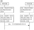
- FIG. 3 is a schematic flowchart of a communication method 200 provided by an embodiment of the present application, which is shown from the perspective of device interaction. As shown, the method 200 shown in FIG. 3 can include steps 210 through 250. Each step will be described in detail below with reference to FIG.
- mapping manner of the downlink demodulation reference signal in the present application is directed to the design of the pre-demodulation reference signal, and the design of the mapping manner of the additional demodulation reference signal is not limited in this application.
- the network device determines, according to the first resource occupied by the SS/PBCH block, a second resource for transmitting a downlink pre-demodulation reference signal, where the first resource and the second resource do not overlap.
- the terminal device determines, according to the first resource occupied by the SS/PBCH block, a second resource for transmitting a downlink pre-demodulation reference signal, where the first resource and the second resource do not overlap.
- the resource for transmitting the SS/PBCH block determined according to the mapping manner of the SS/PBCH block is recorded as the first resource, and the downlink resource is determined according to the first resource.
- the resource of the pre-demodulation reference signal is recorded as the second resource, and the resource determined according to the mapping manner of the downlink demodulation reference signal (for example, mapping type A) is recorded as the third resource.
- the first resource and the second resource do not overlap, and the first resource and the third resource may overlap or may not overlap.
- the third resource is a resource determined according to the mapping manner of the downlink demodulation reference signal, but the downlink demodulation reference signal is not necessarily transmitted by the resource.
- the network device may use the second resource to transmit the downlink pre-demodulation reference signal.
- the second resource and the third resource may be completely different, or may be partially the same.
- the network device may use the third resource to transmit the downlink pre-demodulation reference signal, where the first resource and the third resource do not overlap, in which case the third resource may be determined as the second resource, or Said that the second resource and the third resource can be identical.
- the terminal device may determine, according to the first resource that transmits the SS/PBCH block, the second resource used for transmitting the downlink pre-demodulation reference signal, to avoid A resource conflicts with a second resource.
- the first resource and the second resource do not overlap, and may include: the first resource and the second resource do not overlap in the time domain, and do not overlap in the frequency domain.
- the terminal device and the network device may respectively determine the first resource and the third resource according to a predefined mapping manner to determine whether the two are conflict.
- the terminal device and the network device may determine the first resource according to the subcarrier spacing of the resource and the mapping manner of the predefined SS/PBCH block corresponding to the subcarrier spacing, respectively.
- the mapping between the mapping mode of the SS/PBCH block and the subcarrier spacing may be pre-defined in the protocol.
- the terminal device and the network device may also determine the third resource according to a mapping manner of the downlink demodulation reference signal (eg, mapping type A). Further, it is determined whether the first resource and the third resource overlap.
- the second resource for transmitting the downlink pre-demodulation reference signal is determined according to the first resource when the overlap occurs; and the third resource is directly determined to be used for transmitting the downlink pre-solution if no overlap occurs. Adjust the second resource of the reference signal.
- the terminal device and the network device may respectively determine the first resource according to a mapping manner of the predefined SS/PBCH block, and then according to the first A resource determines a second resource for transmitting a downlink pre-demodulation reference signal. That is to say, corresponding to the mapping manner of the SS/PBCH in different cases, different transmission resources of the downlink pre-demodulation reference signal can be designed, for example, by using different pilot patterns to define various types. The situation is the resource location of the downlink demodulation reference signal. This is equivalent to redefining the mapping position of the downlink pre-demodulation reference signal, regardless of the mapping manner of the existing downlink demodulation reference signal, such as the mapping type A and the mapping type B described above.
- step 230 the network device transmits a downlink pre-demodulation reference signal based on the second resource.
- the terminal device receives the downlink pre-demodulation reference signal based on the second resource.
- the specific process of the network device transmitting the downlink pre-demodulation reference signal by using the second resource and the specific process of the terminal device receiving the downlink pre-demodulation reference signal in the second resource may be the same as the prior art, and for the sake of brevity, the specific A detailed description of the process.
- the terminal device and the network device determine the resource for transmitting the downlink pre-demodulation reference signal according to the resource occupied by the SS/PBCH block, thereby avoiding conflicts between resources, thereby ensuring correct reception of the downlink demodulation reference signal, which is beneficial to Improving the receiving performance of downlink data is beneficial to improving the reliability of data transmission.
- the method 200 further includes:
- step 230 the network device determines a first resource for transmitting the SS/PBCH block.
- the terminal device determines a first resource for transmitting the SS/PBCH block.
- the first resource used for transmitting the SS/PBCH block may be understood as a first resource occupied by the SS/PBCH block, and the first resource may include a frequency domain resource and a time domain resource.
- the location of the first resource in the frequency domain may be predefined, for example, a protocol definition.
- the location of the first resource in the time domain may be determined by the terminal device and the network device based on a predefined mapping manner, respectively.
- the subcarrier spacing is 240 kHz (ie, case E)
- the physical downlink shared channel is not configured. Therefore, the embodiment of the present application mainly describes the SS/ the case of case A to case D, respectively.
- the location of the first resource occupied by the PBCH in the time domain Since the start symbols of the mapping of the SS/PBCH block in the time domain are cycled by 14 or 28 symbols, that is, one or two time slots are cycled. Therefore, in this embodiment, two are used.
- a continuous time slot is taken as an example to describe the mapping manner of case A to case D in detail.
- Case A The subcarrier spacing is 15 kHz, and the first symbol occupied by the candidate SS/PBCH block is numbered ⁇ 2, 8 ⁇ + 14*n. Then, the symbols that may be occupied by the SS/PBCH block in slot #0 and slot #1 are ⁇ 2, 3, 4, 5 ⁇ , ⁇ 8, 9, 10, 11 ⁇ , ⁇ 16, 17, 18, 19 ⁇ and ⁇ 22, 23, 24, 25 ⁇ , as shown in Figure 4.
- Case B The subcarrier spacing is 30 kHz, and the first symbol occupied by the candidate SS/PBCH block is numbered ⁇ 4, 8, 16, 20 ⁇ + 28*n. Then, the symbols that may be occupied by the SS/PBCH block in slot #0 and slot #1 are ⁇ 4, 5, 6, 7 ⁇ , ⁇ 8, 9, 10, 11 ⁇ , ⁇ 16, 17, 18, 19 ⁇ and ⁇ 20, 21, 22, 23 ⁇ , as shown in Figure 5.
- Case C The subcarrier spacing is 30 kHz, and the first symbol occupied by the candidate SS/PBCH block is numbered ⁇ 2, 8 ⁇ + 14 * n. Then, the symbols that may be occupied by the SS/PBCH block in slot #0 and slot #1 are ⁇ 2, 3, 4, 5 ⁇ , ⁇ 8, 9, 10, 11 ⁇ , ⁇ 16, 17, 18, 19 ⁇ and ⁇ 22, 23, 24, 25 ⁇ , as shown in Figure 4.
- Case D The subcarrier spacing is 120 kHz, and the first symbol occupied by the candidate SS/PBCH block is numbered ⁇ 4, 8, 16, 20 ⁇ + 28 * n. Then, the symbols that may be occupied by the SS/PBCH block in slot #0 and slot #1 are ⁇ 4, 5, 6, 7 ⁇ , ⁇ 8, 9, 10, 11 ⁇ , ⁇ 16, 17, 18, 19 ⁇ and ⁇ 20, 21, 22, 23 ⁇ , as shown in Figure 5.
- FIG. 4 and FIG. 5 are only intended to facilitate understanding of the symbols occupied by the candidate SS/PBCH blocks in various cases, and the present application should not be limited in any way.
- the corresponding symbol lengths are different.
- a symbol length corresponding to a subcarrier spacing of 15 kHz may be twice the symbol length corresponding to a subcarrier of 30 kHz.
- FIG. 6 shows a schematic diagram of symbol length relationships corresponding to different subcarrier spacings. It can be seen that the subcarrier spacing and the symbol length have an inverse relationship, and the smaller the subcarrier spacing, the larger the corresponding symbol length.
- the drawings are merely for ease of understanding and should not be construed as limiting the application.
- the method 200 further includes: determining, by the network device, a location of the third resource in the time domain according to a mapping manner of the predefined downlink demodulation reference signal.
- the terminal device determines the third resource according to a mapping manner of the predefined downlink demodulation reference signal.
- the terminal device and the network device may determine a starting position of the third resource in the time domain according to a mapping manner of the predefined downlink demodulation reference signal in the time domain, for example, mapping type A.
- mapping type A the third resource is the second and/or third symbol in each slot, corresponding to the two in FIG. 4 or FIG.
- the symbols corresponding to the third resource in the figure include ⁇ 2, 3, 16, 17 ⁇ .
- method 200 further includes:
- the network device sends indication information of the symbol number k of the downlink pre-demodulation reference signal.
- the terminal device receives the indication information of the symbol number k of the downlink pre-demodulation reference signal.
- the indication information may be a specific value of the symbol number k of the downlink pre-demodulation reference signal, or may be an indication cell having a correspondence relationship with the symbol number k. In an implementation manner, the indication information may be carried in the downlink control information.
- the network device and the terminal device may respectively determine the location of the third resource in the time domain.
- the method 200 further includes:
- the network device determines whether the location of the third resource in the time domain and the first resource overlap.
- the terminal device determines whether the location of the third resource in the time domain and the first resource overlap.
- the network device can determine whether the two overlap according to the predetermined location of the first resource in the time domain and the location of the third resource in the time domain. If not overlapping, the network device may determine that the mapping position of the downlink pre-demodulation reference signal in the time domain is the location of the third resource in the time domain; if overlapping, the network device and the terminal device may further determine that the third resource is in the Whether the location on the frequency domain overlaps with the first resource.
- the method 200 further includes: determining, by the network device, a location of the third resource for transmitting the downlink demodulation reference signal in the frequency domain.
- the terminal device determines a location of the third resource for transmitting the downlink demodulation reference signal in the frequency domain.
- the terminal device may determine, according to the resource indication of the physical downlink shared channel received in advance, the frequency domain location where the third resource is located. Specifically, the network device may indicate, by using the downlink control information, the frequency domain resource of the physical downlink shared channel to the terminal device.
- the network device and the terminal device may further determine the frequency domain location of the third resource and the frequency domain of the first resource. Whether the positions overlap.
- the resources occupied by the downlink demodulation reference signal in the frequency domain may be the same as the resources occupied by the physical downlink shared channel in the frequency domain, or may be part of the resources occupied by the physical downlink shared channel in the frequency domain. . This application is not limited thereto. Regardless of whether the downlink demodulation reference signal occupies the bandwidth of the entire physical downlink shared channel, the network device and the terminal device can further determine the transmission downlink demodulation reference in the frequency band in which the first resource and the third resource overlap. The second resource of the signal.
- the network device and the terminal device may determine, in the case that the first resource and the third resource overlap, the second resource for transmitting the downlink pre-demodulation reference signal, where the first resource and the first resource are In the case that the third resources do not overlap, the downlink pre-demodulation reference signal may still be transmitted by using the third resource.
- the resource for transmitting the downlink pre-demodulation reference signal may be determined along with the mapping mode A in the prior art.
- the network device and the terminal device may still determine the third resource as the second resource; if overlap, the network device and the terminal The device may determine a second resource for transmitting the downlink pre-demodulation reference signal based on the same rule, respectively, whereby the determined second resource and the third resource are at least partially different in the time domain and/or the frequency domain.
- the network device and the terminal device may determine the location of the second resource in the time domain based on any one of the following rules:
- Rule 1 According to the number k of symbols occupied by the downlink demodulation reference signal, the k symbols preceding the symbol occupied by the SS/PBCH block are determined as symbols for transmitting the downlink demodulation reference signal, or the SS/PBCH block is used. The k symbols following the occupied symbols are determined as symbols for transmitting the downlink demodulation reference signal. Where k is 1 or 2;
- Rule 2 Determine, according to the predefined first mapping relationship, a location of the second resource corresponding to the mapping manner of the SS/PBCH block in the time domain.
- the first mapping relationship indicates a one-to-one correspondence between mapping manners of multiple SS/PBCH blocks and symbols that can be mapped by multiple downlink pre-demodulation reference signals;
- Rule 3 determining, according to the predefined second mapping relationship, a location of the fourth resource corresponding to the mapping manner of the SS/PBCH block in the time domain, where the fourth resource is a resource for transmitting the downlink additional demodulation reference signal
- the second mapping relationship indicates a one-to-one correspondence between the mapping manner of the multiple SS/PBCH blocks and the symbols that can be mapped by the multiple downlink additional demodulation reference signals;
- the second resource is determined according to the location of the first resource occupied by the SS/PBCH block in the frequency domain, and the location of the second resource in the frequency domain does not overlap with the location of the first resource in the frequency domain.
- the frequency domain location is not changed in the rules 1 to 3, but the position of the predetermined third resource in the time domain is adjusted, so that the finally determined downlink pre-demodulation reference is used for transmission.
- the time domain resource of the signal does not overlap with the first resource.
- rules 1 to 3 can be used to determine the time domain location of the second resource; the rule 4 does not change the time domain location, indicating that the predetermined third resource is in frequency.
- the position on the domain is adjusted so that the finally determined frequency domain resource for transmitting the downlink pre-demodulation reference signal does not overlap with the first resource.
- Rule 1 considers the case where the downlink additional demodulation reference signal is not configured. That is, the terminal device does not receive resource configuration information of an additional demodulation reference signal from the network device.
- the configuration information of the additional demodulation reference signal is carried in the RRC signaling.
- the downlink demodulation reference signal configured by the network device may include a downlink pre-addition demodulation reference signal.
- the network device and the terminal device may pre-arrange the k symbols before placing the downlink pre-demodulation reference signal in front of the symbol occupied by the SS/PBCH block.
- the physical downlink control channel usually occupies the first m symbols of each slot, and the value of m is 1, 2, or 3, based on the enumeration of symbols occupied by the candidate SS/PBCH block in the foregoing.
- the number of idle symbols p between the candidate SS/PBCH block and the physical downlink control channel may be 0, or 1, or 2, or 3.
- the symbol number k of the downlink pre-demodulation reference signal may be further combined. If k ⁇ p, the k symbols located before the SS/PBCH block in the p idle symbols may be used to carry the downlink.
- the demodulation reference signal is set; if k>p, the p symbols can be preferentially used to carry the downlink pre-demodulation reference signal, that is, the same time domain resource is multiplexed with the physical downlink control channel by frequency division.
- the network device and the terminal device may pre-arrange the k symbols following the symbol occupied by the SS/PBCH block by placing the downlink pre-demodulation reference signal.
- the downlink pre-demodulation reference signal is carried after the symbol occupied by the SS/PBCH block regardless of whether there is an idle symbol between the physical downlink control channel and the candidate SS/PBCH block. On the symbol.
- the downlink is performed.
- the pre-demodulation reference signal is carried on the k symbols following the symbol occupied by the SS/PBCH block.
- the first rule will be described in detail below with reference to the first resource occupied by the SS/PBCH block in FIGS. 4 and 5.
- the symbols ⁇ 2, 3, 4, 5 ⁇ , ⁇ 16, 17, 18, 19 ⁇ in the case A and the case C and the symbols of the third resource are shown.
- the resources occupied by the physical downlink control channel may not be considered.
- the symbol corresponding to symbol #6 or symbol #7 in slot #0 and symbol #20 or symbol #21 in slot #1 may be determined as a downlink predemodulation reference signal for transmission.
- the second resource needs to be determined in combination with the resources occupied by the physical downlink control channel.
- the physical downlink control channel occupies symbol #0 in slot #0 and symbol #14 in slot #1, SS/PBCH block.
- the number of idle symbols p between the physical downlink control channel and the physical downlink control channel is 1.
- the resource corresponding to the symbol #1 in the slot #0 and the symbol #15 in the slot #1 may be determined as the second resource for transmitting the downlink pre-demodulation reference signal.
- the network device and the terminal device may determine, based on k>p, that the downlink pre-demodulation reference signal is placed on the last k symbols of the symbol occupied by the SS/PBCH block, that is, the resource occupied by the physical downlink control channel is not changed.
- the symbols corresponding to the symbols #6 and #7 in the slot #0 and the symbols #20 and #21 in the slot #1 are determined as the second resource for transmitting the downlink pre-demodulation reference signal.
- the symbols corresponding to the symbols #0 and #1 in the slot #0 and the symbols #14 and #15 in the slot #1 may be determined as the downlink predemodulation reference signal for transmission.
- the channel is frequency division multiplexed with the demodulation reference signal.
- the network device and the terminal device may determine, based on k>p, that the downlink pre-demodulation reference signal is placed on the last k symbols of the symbol occupied by the SS/PBCH block, that is, the resource occupied by the physical downlink control channel is not changed.
- Adjusting the second resource of the reference signal; when k 2, determining the resource corresponding to the symbol #6 and the symbol #7 in the slot #0 and the resource corresponding to the symbol #20 and the symbol #21 in the slot #1 as A second resource for transmitting a downlink pre-demodulation reference signal.
- the symbols ⁇ 16, 17, 18, 19 ⁇ in case B and case D and the symbols ⁇ 2, 3, 16, 17 ⁇ of the third resource have overlapping.
- the resources occupied by the physical downlink control channel may not be considered.
- the second resource needs to be determined in combination with the resources occupied by the physical downlink control channel.
- the resource corresponding to the symbol #15 may be determined as the second resource for transmitting the downlink pre-demodulation reference signal.
- the resources corresponding to the symbol #14 and the symbol #15 may be determined as the second resource for transmitting the downlink pre-demodulation reference signal, and the physical downlink control is not configured on the symbol #14.
- the channel, that is, the physical downlink control new channel and the demodulation reference signal are frequency division multiplexed.
- the network device and the terminal device may determine, based on k>p, that the downlink pre-demodulation reference signal is placed on the last k symbols of the symbol occupied by the SS/PBCH block, that is, the resource occupied by the physical downlink control channel is not changed.
- the symbol #24 and the symbol #25 are determined as the second resource for transmitting the downlink pre-demodulation reference signal.
- the physical downlink control channel is not disposed on symbol #14 and symbol #15, that is, the physical downlink control new channel and the demodulation reference signal are frequency division multiplexed.
- the network device and the terminal device may determine, based on k>p, that the downlink pre-demodulation reference signal is placed on the last k symbols of the symbol occupied by the SS/PBCH block, that is, the resource occupied by the physical downlink control channel is not changed.
- Rule 2 also considers the case where the downlink additional demodulation reference signal is not configured. That is, the terminal device receives the resource configuration information of the additional demodulation reference signal from the network device. For example, the terminal device receives the RRC signaling from the network device, where the RRC signaling carries the resource configuration information of the additional demodulation reference signal.
- the downlink demodulation reference signal configured by the network device may include a downlink pre-addition demodulation reference signal.
- the network device and the terminal device may determine, according to the pre-defined first mapping relationship, the location of the second resource in the time domain corresponding to the mapping manner of the SS/PBCH block, where the first mapping relationship indicates multiple SS/PBCH blocks.
- the network device and the terminal device may pre-define the time domain location of the second resource used for transmitting the downlink pre-demodulation reference signal according to different resource overlapping positions in different situations.
- Tables I and II show only two possible scenarios of the first mapping relationship and should not constitute any limitation to the present application.
- the first mapping relationship may also be independent of the design in Rule 1, and the position of the second resource in the time domain is directly determined according to the overlapping symbols in different SS/PBCH mapping modes.
- the first mapping relationship is only one possible implementation form through a table, and should not be arbitrarily limited by the present application.
- the first mapping relationship may also be embodied by a pilot pattern.
- the mapping relationship in Table 1 can be embodied by a pilot pattern, as shown in FIGS. 7 to 9.
- the second resource of the downlink pre-demodulation reference signal has the same position in the time domain, so it can be represented by a pilot pattern.
- 7 and FIG. 9 are pilot patterns of the downlink pre-demodulation reference signal corresponding to case B and case D, FIG. 7 shows an example of the pilot pattern of the even-numbered time slots, and FIG. 9 shows the odd-numbered numbers. An example of a pilot pattern for a time slot.
- pilot pattern is not limited to that shown in FIG. 7 to FIG. 9.
- the pilot pattern obtained by the mapping relationship in Table 2 above may be different from FIG. 7 to FIG. 9.
- here is not List them one by one.
- Rule 3 considers the case where a downlink additional demodulation reference signal is configured.
- the method 200 further includes: receiving, by the terminal device, resource configuration information of the downlink additional demodulation reference signal.
- the network device sends resource configuration information of the downlink additional demodulation reference signal.
- the resource configuration information of the downlink additional demodulation reference signal is carried in the RRC signaling. That is, the terminal device receives the RRC signaling from the network device, where the RRC signaling carries the resource configuration information of the downlink additional demodulation reference signal.
- the downlink demodulation reference signal configured by the network device may include a downlink additional demodulation reference signal and may include a downlink pre-demodulation reference signal and a downlink additional demodulation reference signal.
- the network device and the terminal device may further determine whether the pre-configured resource for transmitting the downlink additional demodulation reference signal overlaps with the SS/PBCH block in the time domain.
- the pre-configured resources for transmitting the downlink additional demodulation reference signal are recorded as the fourth resource in the present application. If the fourth resource and the first resource do not overlap in the time domain, the network device and the terminal device may directly map the downlink pre-demodulation reference signal to the fourth resource, that is, use the fourth resource as the second resource.
- the network device and the terminal device may use the k symbols after the SS/PBCH block to transmit the downlink pre-demodulation reference signal, ie, The resource corresponding to the k symbols after the SS/PBCH is determined as the second resource; in another implementation manner, the network device and the terminal device may determine, according to the foregoing rule 1 or rule 2, the second resource is in time The location on the domain.
- the downlink pre-demodulation reference signal may be placed on the symbol after the SS/PBCH block.
- there may be 2 or 4 symbols after the SS/PBCH block if there are only 2 symbols remaining after the SS/PBCH block (for example, slot #0 shown in FIG. 4)
- the symbol #12 and the symbol #13), the resource corresponding to at least one of the two symbols can be used as the second resource, and can be used for transmitting the downlink pre-demodulation reference signal, in this case, due to the additional demodulation reference signal
- the downlink additional demodulation reference signal may not be transmitted; if the SS/PBCH block is from the rear symbol There are 4 remaining (for example, symbol #24 to symbol #27 in slot #1 shown in Fig. 5), then the first of the 4 symbols (for example, symbol #24) or the first two symbols (for example, symbol) #24 ⁇ #25)
- the corresponding resource can be used as the second resource, and can be used to transmit the downlink pre-demodulation reference signal. If the second resource occupies only one symbol (for example, symbol #24), the last two of the four symbols Symbols (for example, symbol #26 and symbol #27) may be used to transmit downlink additional demodulation parameters. Test signal.
- the resource corresponding to any symbol after the symbol occupied by the data signal can be used to transmit the downlink additional demodulation reference signal.
- the resource corresponding to the last symbol of the four symbols can be used to transmit the downlink additional demodulation reference signal.
- the network device and the terminal device may determine the second resource according to the location of the first resource occupied by the SS/PBCH in the frequency domain, so that the location of the second resource in the frequency domain does not overlap with the location of the first resource in the frequency domain. .
- the network device and the terminal device may determine the second resource according to the predetermined location of the first resource in the frequency domain and the location of the third resource in the time domain, where the second resource is in the frequency domain A resource is staggered, and the location in the time domain may be the same as or different from the first resource, which is not limited in this application. That is to say, the network device and the terminal device can determine the location for the second resource in the time domain according to the mapping manner of the predefined downlink pre-demodulation reference signal, for example, the mapping type A.
- rule 4 is equivalent to transmitting the downlink pre-demodulation reference signal on the frequency domain resource overlapping between the first resource and the third resource, that is, not transmitting on the frequency domain resource overlapping between the first resource and the third resource. data.
- FIG. 10 shows a pilot pattern of a demodulation reference signal determined based on rule four.
- the SS/PBCH block occupies 20 consecutive RBs (or 240 consecutive subcarriers) in the frequency domain.
- RB#21 to RB#40 may be included, and the 20 channels may be used.
- the physical downlink shared channel is not configured on the RB, and the physical downlink shared channel is configured on the resource in which the SS/PBCH block is not configured, for example, in RB#0 to RB#20, and RB#41 to RB#47. In this case, even if the position of the downlink pre-demodulation reference signal in the time domain is the same in the time domain, the resource collision does not occur.
- the figure only shows the resources occupied by the SS/PBCH and the physical downlink shared channel, but this should not constitute any limitation to the present application.
- the present application is occupied by the SS/PBCH in the frequency domain.
- the location of the resource is not limited.
- the mapping manner of the network device to the physical downlink shared channel is not limited.
- each example is described by taking the number of the symbol corresponding to the resource occupied by the SS/PBCH as an example, but this should not constitute any limitation on the present application, and the scheduled physical downlink shared channel
- the number of the symbol may be different from the number of the SS/PBCH.
- the symbol number in each slot may start from 0.
- the location of the resource of the downlink pre-demodulation reference signal is determined by the embodiment provided above, but the corresponding symbol number in the physical downlink shared channel is the same as above. The difference shown.
- rule four can also be used in combination with any one of rule 1, rule two or rule three, that is, simultaneously changing the position of the time-frequency resource of the downlink pre-demodulation reference signal. For the sake of brevity, details are not described here.
- the network device and the terminal device may determine resources for transmitting the downlink pre-demodulation reference signal based on the same rule, for example, rules 1 to 4 listed above, so that the downlink can be transmitted based on the same resource.
- the demodulation reference signal is set, and then the downlink demodulation reference signal can be correctly received to demodulate the downlink data. Therefore, the receiving performance of the downlink data can be improved, and the reliability of the data transmission is improved.
- the network device and the terminal device may not pre-determine whether the first resource and the third resource overlap, and directly determine, according to the first resource occupied by the SS/PBCH block, a channel for transmitting the downlink pre-demodulation reference signal. Two resources.
- the method 200 further includes:
- step 230 the network device determines a first resource for transmitting the SS/PBCH block.
- the terminal device determines a first resource for transmitting the SS/PBCH block.
- step 230 and step 240 have been described in detail in the first embodiment, and will not be further described herein for the sake of brevity.
- the network device and the terminal device may determine, according to the first resource that transmits the SS/PBCH, a second resource for transmitting the downlink pre-demodulation reference signal.
- a second resource for transmitting the downlink pre-demodulation reference signal.
- the network device and the terminal device may be configured to transmit the downlink pre-demodulation reference signal according to the first resource occupied by the SS/PBCH block.
- the second resource For example, in case A and case C, the location of the second resource on the time domain can be directly defined.
- defining the second resource occupying the first or first two symbols of each time slot in the time domain, or the last or last two symbols of each time slot, or the middle of each time slot is located at two One or two symbols between SS/PBCH blocks.
- the position of the second resource in the time domain can also be directly defined.
- the second resource is defined to occupy the last or last two symbols of each time slot in the time domain, or one or two symbols before the SS/PBCH block of each time slot.
- the location of the second resource listed above in the time domain is merely an example and should not be construed as limiting the application.
- the location of the second resource in the time domain may be the same as the location of the second resource defined in rules 1 through 3 listed above in the time domain.
- the location of the second resource in the time domain may be redefined according to the location of the first resource in the time domain, which is not limited in this application.
- the network device and the terminal device may determine, according to a predefined rule, a resource used for transmitting the downlink pre-demodulation reference signal, so that the downlink pre-demodulation reference signal may be transmitted based on the same resource, thereby being able to correctly
- the downlink demodulation reference signal is received to demodulate the downlink data. Therefore, it is advantageous to improve the receiving performance of downlink data and improve the reliability of data transmission.
- the two mapping modes of the uplink demodulation reference signal in the current protocol do not clearly define the used scenario, which may cause the network device and the terminal device to understand the mapping position of the demodulation reference signal.
- the terminal device may determine the resource of the uplink demodulation reference signal according to the mapping type A and send the uplink demodulation reference signal, and the network device may determine, according to the mapping type B, that the resource receives the uplink demodulation reference signal on the resource.
- the network device may not correctly receive the uplink demodulation reference signal sent by the terminal device, thereby causing the receiving performance of the uplink transmission, so that the reliability of the data transmission is reduced.
- the present application further provides a communication method, which enables a network device and a terminal device to determine resources for transmitting an uplink demodulation reference signal based on the same rule, so that the network device can correctly receive an uplink demodulation reference signal, thereby improving uplink data. Transmission performance.
- FIG. 11 is a schematic flowchart of a communication method 300 provided by an embodiment of the present application, which is shown from the perspective of device interaction. As shown, the method 300 shown in FIG. 11 can include steps 310 through 360. Each step will be described in detail below with reference to FIG.
- step 310 the terminal device determines, according to the received slot format indication (SFI), the resource for transmitting the uplink demodulation reference signal by using the first mapping manner.
- SFI slot format indication
- the network device determines, according to the transmitted SFI, the resource for transmitting the uplink demodulation reference signal by using the first mapping manner.
- the network device and the terminal device may pre-arrange the resource mapping based on the first mapping manner when the terminal device receives the SFI from the network device.
- SFI can be used to indicate information such as the type of time slot.
- the time slot type may include: a pure uplink time slot, a pure downlink time slot, an uplink-based time slot, or a downlink-based time slot.
- the ratio of uplink and downlink symbols in the uplink-based time slot or the downlink-based time slot may also be different.
- the network device can indicate the slot type, for example, by transmitting an index of a different slot type.
- the network device can use different time slot ratios on different radio frames, that is, DTDD can be implemented.
- the SFI can be used to implicitly instruct the terminal device to communicate in DTDD mode.
- the resource for transmitting the uplink demodulation reference signal may be determined by the first mapping manner.
- the SFI is carried in the downlink control information.
- the SFI can be carried in downlink control information in a specific format. That is to say, when the terminal device receives the downlink control information of the specific format, it can be considered that the network device sends the SFI and can communicate in the DTDD mode.
- the SFI may be specifically carried in the DCI of format 2_0, ie, DCI format 2_0.
- the method further includes: Step 330: The terminal device receives resource indication information of the downlink control information.
- the network device sends resource indication information of the downlink control information.
- the transmission resource of the downlink control information may be indicated in the high layer signaling, for example, RRC signaling.
- the network device may indicate the transmission resource of the DCI format 2_0 in the RRC signaling. Therefore, the terminal device may determine to perform resource mapping based on the first mapping manner when receiving the resource indication information of the DCI format 2_0.
- the first mapping mode may be the mapping type A of the uplink demodulation reference signal defined in the NR.
- mapping type A of the uplink demodulation reference signal The details of the mapping type A of the uplink demodulation reference signal are described in detail above, and are not described herein for brevity.
- mapping type A is an example of the first mapping manner, and the present application should not be limited. The present application does not preclude the possibility of defining other mapping types or mapping manners in the future protocol instead of the mapping method A.
- the terminal device can communicate with the network device by using the DTDD mode based on the received SFI, which can improve the utilization of the spectrum resource.
- the downlink demodulation reference signal is mapped by the mapping method A in the normal case, if the uplink demodulation reference signal is also mapped in the mapping mode A for resource mapping in the DTDD mode, the uplink and downlink solutions can be made.
- the probability that the reference signal is aligned in the time domain increases.
- the inter-cell interference is a major factor affecting the signal quality
- the uplink and downlink demodulation reference signals are aligned in the time domain to facilitate the conversion of the anisotropic interference into the same-direction interference.
- the embodiment of the present application considers the mapping manner of the uplink demodulation reference signal in the DTDD mode as the mapping type A, which is beneficial to realize the symmetric design of the uplink and downlink, thereby facilitating interference estimation and elimination, and enabling data transmission in the DTDD mode. The quality is improved.
- the method further includes: Step 340: The terminal device determines, by using the second mapping manner, the resource for transmitting the uplink demodulation reference signal, if the SFI is not received.
- the method further includes: Step 350: The network device determines, by using the second mapping manner, the resource for transmitting the uplink demodulation reference signal, if the SFI is not sent.
- the SFI can be carried in downlink control information in a specific format. If the terminal device does not receive the downlink control information of the specific format, it may be considered that the network device is not configured with the SFI. In this case, the terminal device can communicate with the network device in a TDD mode according to the system information block (SIB) or the TDD configuration information carried in the RRC signaling. At this time, the terminal device and the network device may determine, by using the second mapping manner, resources for transmitting the uplink demodulation reference signal, respectively.
- SIB system information block
- the terminal device and the network device may determine, by using the second mapping manner, resources for transmitting the uplink demodulation reference signal, respectively.
- the TDD configuration information may include at least one of the following: a subcarrier interval, a slot cycle period, and a total downlink slot number x1 at the forefront of each cycle.
- the TDD configuration information may include at least one of the following: a slot cycle period, a number of slots, an uplink symbol number and a downlink symbol number in each slot.
- TDD configuration information is merely exemplary and should not be construed as limiting the present application.
- the present application does not exclude the possibility of adding more information or deleting some information to the TDD configuration information in future protocols.
- signaling for carrying TDD configuration information is merely exemplary, and should not be construed as limiting the present application.
- the present application does not preclude the possibility of carrying TDD configuration information by other signaling in future protocols.
- the second mapping mode may be a mapping type B of the uplink demodulation reference signal defined in the NR.
- mapping type B of the uplink demodulation reference signal The details of the mapping type B of the uplink demodulation reference signal are described in detail above, and are not described herein for brevity.
- mapping type B is taken as an example of the second mapping manner, and the present application should not be limited.
- the present application does not preclude the possibility of defining other mapping types or mapping manners in the future protocol instead of the mapping type B. Since it is defined in the current protocol, the mapping type A of the uplink demodulation reference signal is limited to use in pure uplink time slots, that is, when one radio frame includes multiple time slot types, and is not limited to pure uplink time slots. It is necessary to switch to mapping type B to determine the resource for transmitting the uplink demodulation reference signal. This switching causes the complexity of the processing of the terminal device. Therefore, it is directly defined that the resource for transmitting the uplink demodulation reference signal is determined by mapping type B when the SFI is not configured.
- step 360 the terminal device transmits an uplink demodulation reference signal.
- step 360 the network device receives the uplink demodulation reference signal.
- the terminal device may transmit the uplink demodulation reference signal according to the resource determined in step 310, and the network device may receive the uplink demodulation reference signal according to the resource determined in step 320.
- the resource determined in step 320 is the same; if the SFI does not receive the SFI, the terminal device may transmit the uplink demodulation reference signal according to the resource determined in step 340, and the network device may receive the uplink solution according to the resource determined in step 350.
- the reference signal it can be understood that the resources determined in steps 340 and 350 are the same.
- the specific process for the terminal device to transmit the uplink demodulation reference signal by using the determined resource and the specific process for the network device to receive the uplink demodulation reference signal on the resource may be the same as the prior art, and the details of the specific process are omitted here for brevity. Description.
- the terminal device and the network device may determine the mapping manner of the uplink demodulation reference signal based on the same determination condition, so that the uplink demodulation reference signal can be transmitted on the same resource. Therefore, the network device can correctly receive the uplink demodulation reference signal to demodulate the uplink data, which is beneficial to improving the receiving performance of the uplink data and improving the reliability of the data transmission.
- FIG. 12 is a schematic flowchart of a communication method 400 provided by an embodiment of the present application, which is shown from the perspective of device interaction. As shown, the method 400 shown in FIG. 12 can include steps 410 through 430. Each step will be described in detail below with reference to FIG.
- the terminal device determines, according to the received SFI and the first indication information, a resource for transmitting an uplink demodulation reference signal by using a first mapping manner, where the first indication information indicates that the waveform of the uplink transmission is a multi-carrier.
- the network device determines, according to the sent SFI and the first indication information, the resource for transmitting the uplink demodulation reference signal by using the first mapping manner; wherein the first indication information indicates that the waveform of the uplink transmission is multiple Carrier.
- the SFI can be used to implicitly instruct the terminal device to communicate in DTDD mode.
- the first indication information may be used to indicate that the waveform of the uplink transmission is a multi-carrier, for example, a discrete Fourier transform-spread OFDM (DFT-s-OFDM) waveform based on a discrete Fourier transform extension.
- DFT-s-OFDM discrete Fourier transform-spread OFDM
- the network device and the terminal device determine to communicate in the DTDD mode, and determine that the resource for transmitting the uplink demodulation reference signal is determined by the first mapping manner in the case where the multi-carrier modulation technique is employed in the uplink.
- the method further includes: Step 430: The terminal device receives resource indication information, where the resource indication information indicates a transmission resource that carries downlink control information of the SFI.
- the network device sends resource indication information indicating the transmission resource of the downlink control information of the SFI.
- step 430 is the same as the specific process of step 330 in method 300, and is not described herein again for brevity.
- the method further includes: Step 440: The terminal device receives the high layer signaling, where the high layer signaling carries the first indication information.
- step 440 the network device sends high layer signaling, where the high layer signaling carries the first indication information.
- the first indication information may be carried in the RRC signaling.
- the first indication information may be indicated by a transformprecoding field in the RRC signaling. For example, when the field is set to “0”, the indication waveform is a multi-carrier.
- the first mapping manner includes a mapping manner A defined in the NR protocol.
- mapping type A of the uplink demodulation reference signal The details of the mapping type A of the uplink demodulation reference signal are described in detail above, and are not described herein for brevity.
- mapping type A is an example of the first mapping manner, and the present application should not be limited. The present application does not preclude the possibility of defining other mapping types or mapping manners in the future protocol instead of the mapping method A.
- the network device and the terminal device may pre-arrange the resource mapping based on the first mapping manner when the terminal device receives the SFI from the network device and the waveform of the uplink transmission is multi-carrier.
- the judgment condition for using the first mapping mode is increased, and in the case where the SFI is received and multi-carrier modulation is employed, the transmission uplink demodulation is determined by the first mapping mode.
- the resource of the reference signal Due to the multi-carrier modulation technology commonly used in downlink transmission, multi-carrier modulation technology is also used in the uplink to provide a basis for the symmetric design of uplink and downlink pilots, so that the probability of uplink and downlink demodulation reference signals increases in the time domain. Therefore, it is also more conducive to interference estimation and elimination, so that the quality of DTDD mode data transmission is improved.
- the method further includes: Step 450, the terminal device determines, by using the second mapping manner, the resource for transmitting the uplink demodulation reference signal, if the SFI is not received and/or the second indication information is received;
- the two indication information indicates that the waveform of the uplink transmission is a single carrier.
- the network device determines, by using the second mapping manner, the resource for transmitting the uplink demodulation reference signal, in the case that the SFI is sent and/or the second indication information is sent, where the second indication information indicates the uplink.
- the transmitted waveform is a single carrier
- the network device does not send the SFI to the terminal device, that is, the DTDD mode communication is not applicable.
- the second indication information may be used to indicate that the waveform of the uplink transmission is a single carrier, for example, a single carrier frequency division multiple address (SC-FDMA) or the like.
- SC-FDMA single carrier frequency division multiple address
- the terminal device when the terminal device receives only the SFI, or only receives the second indication information, or does not receive the SFI and the second indication information, the second mapping mode is still adopted.
- the terminal device can communicate with the network device in the TDD mode according to the TDD configuration information carried in the SIB or the RRC if the SFI is not received.
- the first indication information and the second indication information may be different indication bits carried in the same field in the RRC signaling.
- the DFT precoding field in the RRC signaling when this field is set to "0", may indicate that the waveform is a single carrier.
- the second mapping mode may be a mapping type B of the uplink demodulation reference signal defined in the NR.
- mapping type B of the uplink demodulation reference signal The details of the mapping type B of the uplink demodulation reference signal are described in detail above, and are not described herein for brevity.
- mapping type B is taken as an example of the second mapping manner, and the present application should not be limited.
- the present application does not preclude the possibility of defining other mapping types or mapping manners in the future protocol instead of the mapping type B. Since it is defined in the current protocol, the mapping type A of the uplink demodulation reference signal is limited to use in the pure uplink time slot, that is, when a radio frame includes multiple time slot types, it is necessary to switch to the mapping type B. A resource for transmitting an uplink demodulation reference signal is determined. This switching causes the complexity of the processing of the terminal device. Therefore, it is directly defined that the resource for transmitting the uplink demodulation reference signal is determined by mapping type B when the SFI is not configured.
- step 470 the terminal device transmits an uplink demodulation reference signal.
- the network device receives the uplink demodulation reference signal.
- the terminal device may transmit the uplink demodulation reference signal according to the resource determined in step 410, and the network device may receive the uplink demodulation reference signal according to the resource determined in step 420, where the terminal device receives the SFI and the first indication information. It can be understood that the resources determined in step 410 and step 420 are the same; if the terminal device receives the SFI and/or receives the second indication information, the terminal device may transmit the uplink demodulation reference signal according to the resource determined in step 450.
- the network device may receive the uplink demodulation reference signal according to the resource determined in step 460. It may be understood that the resources determined in step 450 and step 460 are the same.
- the specific process for the terminal device to transmit the uplink demodulation reference signal by using the determined resource and the specific process for the network device to receive the uplink demodulation reference signal on the resource may be the same as the prior art, and the details of the specific process are omitted here for brevity. Description.
- the terminal device and the network device may determine the mapping manner of the uplink demodulation reference signal based on the same determination condition, so that the uplink demodulation reference signal can be transmitted on the same resource. Therefore, the network device can correctly receive the uplink demodulation reference signal to demodulate the uplink data, which is beneficial to improving the receiving performance of the uplink data and improving the reliability of the data transmission.
- FIG. 13 is a schematic block diagram of a communication device 500 provided by an embodiment of the present application. As shown in FIG. 13, the communication device 500 can include a determining unit 510 and a communication unit 520.
- the communication device 500 can be a network device, or a chip configured in a network device.
- the determining unit 510 is configured to determine, according to the first resource occupied by the SS/PBCH block, a second resource for transmitting the downlink pre-demodulation reference signal, where the first resource does not overlap with the second resource;
- the communication unit 520 is operable to transmit a downlink pre-demodulation reference signal based on the second resource.
- the communication device 500 can be a terminal device or a chip disposed in the terminal device.
- the determining unit 510 is configured to determine, according to the first resource occupied by the SS/PBCH block, a second resource for transmitting the downlink pre-demodulation reference signal, where the first resource does not overlap with the second resource;
- the communication unit 520 is configured to receive the downlink pre-demodulation reference signal based on the second resource.
- the determining unit 510 is further configured to determine the third resource according to the downlink pre-demodulation reference signal mapping type A.
- the first resource and the third resource overlap in a frequency domain, and the first resource and the third resource partially overlap or overlap in the time domain.
- the determining unit 510 is specifically configured to determine, according to the location of the first resource occupied by the SS/PBCH block in the time domain, the location of the second resource used for transmitting the downlink pre-demodulation reference signal in the time domain, the first resource and the first resource The two resources do not overlap in the time domain.
- the determining unit 510 is specifically configured to determine, according to the number of symbols k occupied by the downlink pre-demodulation reference signal, k symbols before the symbol occupied by the SS/PBCH block as a symbol used for transmitting the downlink demodulation reference signal; or
- the k symbols following the symbols occupied by the SS/PBCH block are determined as symbols for transmitting the downlink pre-demodulation reference signal according to the number k of symbols occupied by the downlink pre-demodulation reference signal.
- the determining unit 510 is specifically configured to determine, according to the predefined first mapping relationship, a location of the second resource in the time domain corresponding to the mapping manner of the SS/PBCH block;
- the first mapping relationship indicates a one-to-one correspondence between the mapping manner of the at least one SS/PBCH block and the time domain position mapable by the at least one downlink pre-demodulation reference signal, and the mapping manner of the SS/PBCH block is used to determine the SS.
- the determining unit 510 is specifically configured to determine, according to the fourth resource used for transmitting the downlink additional demodulation reference signal, whether the fourth resource overlaps with the first resource in the time domain, where the fourth resource and the third resource are in the frequency domain.
- the upper device overlaps; and in a case where the fourth resource does not overlap with the first resource in the time domain, the network device determines the fourth resource as the second resource.
- the first resource and the third resource overlap in a frequency domain, and the first resource and the third resource partially overlap or overlap in the time domain.
- the determining unit 510 is specifically configured to determine, according to a location of the first resource occupied by the SS/PBCH block in the frequency domain, a location of the second resource used for transmitting the downlink demodulation reference signal in the frequency domain, the first resource and the second resource. Do not overlap in the frequency domain.
- the communication device 500 can be a terminal device or a chip configured in the terminal device.
- the determining unit 510 is configured to indicate, according to the received slot format, the SFI, and determine, by using the first mapping manner, a resource used for transmitting the uplink demodulation reference signal;
- Communication unit 520 can be configured to transmit an uplink demodulation reference signal on the resource.
- the communication device 500 can be a terminal device or a chip disposed in the terminal device.
- the determining unit 510 is configured to determine, according to the received slot format indication SFI and the first indication information, a resource for transmitting an uplink demodulation reference signal by using a first mapping manner, where the first indication information indicates a waveform of the uplink transmission.
- Multi-carrier
- Communication unit 520 can transmit an uplink demodulation reference signal on the resource.
- the communication unit 520 is further configured to receive resource indication information, where the resource indication information indicates a transmission resource that carries downlink control information of the SFI.
- the communication device 500 can be a network device, or a chip configured in a network device.
- the determining unit 510 may indicate the SFI according to the sent slot format, and determine, by using the first mapping manner, a resource for transmitting the uplink demodulation reference signal;
- Communications unit 520 can receive an uplink demodulation reference signal on the resource.
- the communication device 500 can be a network device or a chip disposed in the network device.
- An uplink demodulation reference signal is received on the resource.
- the communication unit 520 is further configured to send resource indication information, where the resource indication information indicates a transmission resource that carries downlink control information of the SFI.
- FIG. 14 is another schematic block diagram of a communication device 600 provided by an embodiment of the present application.
- the apparatus 600 includes a processing unit 610 and a communication unit 620.
- the communication device 600 further includes a storage unit 630.
- the processing unit 610, the storage unit 620, and the storage unit 630 communicate with each other through an internal connection path to transfer control and/or data signals.
- the communication unit 610 may be a device having a transceiving function for communicating with other communication devices.
- the storage unit 630 can include one or more memories, and the memory 630 can be one or more devices, a period of circuitry for storing programs or data.
- the storage unit 630 can exist independently and is connected to the processing unit 610 through an internal connection path.
- the storage unit can also be integrated with the processing unit 610.
- the communication device 600 can be used in a communication device, circuit, hardware component or chip.
- the communication device 600 can be a network device in the embodiment of the present application.
- a schematic diagram of the network device can be as shown in FIG. 15.
- the communication unit 620 of the communication device 600 can include an antenna and a transceiver (or transceiver), such as the antenna 750 and transceiver 730 shown in FIG.
- the communication device 600 can also include a network interface, such as the network interface 740 shown in FIG.
- the communication device 600 is a chip disposed in a network device in the embodiment of the present application.
- the communication unit 620 of the communication device 600 may include an input or output interface, a pin or a circuit, and the like.
- the storage unit 630 may store computer-executed instructions of the method performed by the network device to cause the processing unit 610 to perform the method performed by the network device in the above embodiments.
- the storage unit 630 can be a register, a cache, or a random access memory (RAM).
- the storage unit 630 can be integrated with the processing unit 610.
- the storage unit 630 can be a read-only memory (ROM).
- ROM read-only memory
- storage unit 630 can be separate from processing unit 610.
- the transceiver can be integrated on the communication device 600, for example, the communication unit 620 integrates the transceiver.
- the device 600 may include a unit for performing the method performed by the network device in FIG. 3, FIG. 11, or FIG. 12, and
- the units in the apparatus 600 and the other operations and/or functions described above are respectively configured to implement the respective processes of the communication method 200 of FIG. 3, the communication method 300 of FIG. 11, or the communication method 400 of FIG.
- the specific process of performing the above-mentioned corresponding steps in each unit refer to the description of the method embodiment in conjunction with FIG. 3 to FIG. 12 in the foregoing, and for brevity, details are not described herein again.
- the communication device 600 can be the terminal device in the embodiment of the present application, and the schematic diagram of the terminal device can be as shown in FIG. 16.
- the communication unit 620 of the communication device 600 can include an antenna and a transceiver, such as the antenna 860 and the transceiver 820 shown in FIG.
- the communication device 600 may further include an output device and an input device, such as the output device 840 and the input device 850 shown in FIG.
- the communication device 600 may be a chip disposed in a terminal device in the embodiment of the present application.
- Communication unit 610 can be an input or output interface, a pin or a circuit, or the like.
- the storage unit 630 may store computer-executed instructions of the method performed by the terminal device to cause the processing unit 610 to perform the method of the terminal device in the above embodiment.
- the storage unit 630 can be a register, a cache or a RAM, etc., and the storage unit 630 can be integrated with the processing unit 610; the storage unit 630 can be a ROM or other type of static storage device that can store static information and instructions, and the storage unit 630 can Processing unit 610 is independent.
- the transceiver can be integrated on the communication device 600, for example, the communication unit 620 integrates the transceiver 820.
- the device 600 may include a unit for performing the method performed by the terminal device in FIG. 3, FIG. 11, or FIG. 12, and
- the units in the apparatus 600 and the other operations and/or functions described above are respectively configured to implement the respective processes of the communication method 200 of FIG. 3, the communication method 300 of FIG. 11, or the communication method 400 of FIG.
- the specific process of performing the above-mentioned corresponding steps in each unit refer to the description of the method embodiment in conjunction with FIG. 3 to FIG. 12 in the foregoing, and for brevity, details are not described herein again.
- FIG. 15 is a schematic structural diagram of a network device 700 according to an embodiment of the present application.
- the network device 700 can include at least one processor 710, at least one memory 720, at least one transceiver 730, at least one network interface 740, and one or more antennas 750.
- the internal connection paths of the processor 710, the memory 720, the transceiver 730, and the network interface 740 are connected.
- Antenna 750 is coupled to transceiver 730.
- Network interface 740 is used to cause network device 700 to connect to other communication devices over a communication link.
- the connection may include various types of interfaces, transmission lines, buses, and the like, which are not limited in this embodiment.
- Memory 720 can exist independently and be coupled to processor 710. Alternatively, the memory 720 can also be integrated with the processor 710, such as integrated within a single chip.
- the memory 720 can store the program code for executing the technical solution of the embodiment of the present application, and is controlled by the processor 710.
- the various types of computer program code to be executed can also be regarded as the driver of the processor 710.
- the processor 710 is configured to execute the computer program code stored in the memory 720, thereby implementing the technical solution in the embodiment of the present application.
- the transceiver 730 can be used to support the reception or transmission of radio frequency signals between the network device and the terminal, and the transceiver 730 can be coupled to the antenna 750.
- the transceiver 730 includes a transmitter Tx and a receiver Rx.
- one or more antennas 750 can receive radio frequency signals
- receiver Rx of transceiver 730 is configured to receive the radio frequency signals from an antenna and convert the radio frequency signals into digital baseband signals or digital intermediate frequency signals, and the digital A baseband signal or digital intermediate frequency signal is provided to the processor 710 for the processor 710 to further process the digital baseband signal or digital intermediate frequency signal, such as demodulation processing and decoding processing.
- the transmitter Tx in the transceiver 730 is further configured to receive the modulated digital baseband signal or digital intermediate frequency signal from the processor 710, and convert the modulated digital baseband signal or digital intermediate frequency signal into a radio frequency signal, and pass through a Or the plurality of antennas 750 transmit the radio frequency signals.
- the receiver Rx may selectively perform one or more stages of downmix processing and analog to digital conversion processing on the radio frequency signal to obtain a digital baseband signal or a digital intermediate frequency signal, the downmix processing and the analog to digital conversion processing. The order is adjustable.
- the transmitter Tx can selectively perform one or more stages of up-mixing processing and digital-to-analog conversion processing on the modulated digital baseband signal or the digital intermediate frequency signal to obtain a radio frequency signal, the upmixing processing and the digital to analog conversion processing.
- the order of precedence is adjustable.
- Digital baseband signals and digital intermediate frequency signals can be collectively referred to as digital signals.
- FIG. 16 is a schematic structural diagram of a terminal device 800 according to an embodiment of the present application.
- the terminal device 800 can include at least one processor 810, at least one transceiver 820, and at least one memory 830.
- the processor 810, the memory 830, and the transceiver 820 are connected.
- the terminal 121 may further include an output device 840, an input device 850, and one or more antennas 860.
- the antenna 860 is coupled to the transceiver 820, and the output device 840 and the input device 850 are coupled to the processor 810.
- Transceiver 820, memory 830, and antenna 860 can implement similar functions with reference to the related description in FIG.
- the processor 810 can be a baseband processor or a CPU, and the baseband processor and the CPU can be integrated or separated.
- the processor 810 can be used to implement various functions for the terminal, such as for processing communication protocols and communication data, or for controlling the entire terminal device, executing a software program, processing data of the software program, or for assisting completion. Computing processing tasks, such as graphics image processing or audio processing, etc.; or processor 810 for implementing one or more of the above functions
- Output device 840 is in communication with processor 810 and can display information in a variety of ways.
- the output device 840 may be a liquid crystal display (LCD), a light emitting diode (LED) display device, a cathode ray tube (CRT) display device, or a projector.
- Input device 850 is in communication with processor 810 and can accept user input in a variety of ways.
- input device 850 can be a mouse, keyboard, touch screen device, or sensing device, and the like.
- the processor in the embodiment of the present application may include at least one of the following types: a general-purpose central processing unit (CPU), a digital signal processor (DSP), a microprocessor, and an application-specific integrated circuit ASIC. (ASIC), Microcontroller Unit (MCU), Field Programmable Gate Array (FPGA), or integrated circuit for implementing logic operations.
- the processor can be a single-CPU processor or a multi-core processor. At least one processor may be integrated in one chip or on multiple different chips.
- the memory in the embodiments of the present application may include at least one of the following types: a read only memory (ROM) or other type of static storage device that can store static information and instructions, random access memory (RAM) or may be stored.
- ROM read only memory
- RAM random access memory
- EEPROM electrically erasable programmabler-only memory
- the memory may also be a compact disc read-only memory (CD-ROM) or other optical disc storage, and a disc storage (including a compact disc, a laser disc, a compact disc, a digital versatile disc, a Blu-ray disc, etc.)
- CD-ROM compact disc read-only memory
- disc storage including a compact disc, a laser disc, a compact disc, a digital versatile disc, a Blu-ray disc, etc.
- the application further provides a computer program product, comprising: computer program code, when the computer program code is run on a computer, causing the computer to perform FIG. 3, FIG. 11 or The method in the embodiment shown in Fig. 12.
- the application further provides a computer readable medium storing program code, when the program code is run on a computer, causing the computer to perform FIG. 3, FIG. 11 or The method in the embodiment shown in Fig. 12.
- the application further provides a system, including the foregoing one or more network devices and one or more terminal devices.
- the disclosed systems, devices, and methods may be implemented in other manners.
- the device embodiments described above are merely illustrative.
- the division of the unit is only a logical function division.
- there may be another division manner for example, multiple units or components may be combined or Can be integrated into another system, or some features can be ignored or not executed.
- the mutual coupling or direct coupling or communication connection shown or discussed may be an indirect coupling or communication connection through some interface, device or unit, and may be in an electrical, mechanical or other form.
- the units described as separate components may or may not be physically separated, and the components displayed as units may or may not be physical units, that is, may be located in one place, or may be distributed to multiple network units. Some or all of the units may be selected according to actual needs to achieve the purpose of the solution of the embodiment.
- each functional unit in each embodiment of the present application may be integrated into one processing unit, or each unit may exist physically separately, or two or more units may be integrated into one unit.
- the functions may be stored in a computer readable storage medium if implemented in the form of a software functional unit and sold or used as a standalone product.
- the technical solution of the present application which is essential or contributes to the prior art, or a part of the technical solution, may be embodied in the form of a software product, which is stored in a storage medium, including
- the instructions are used to cause a computer device (which may be a personal computer, server, or network device, etc.) to perform all or part of the steps of the methods described in various embodiments of the present application.
- the foregoing storage medium includes: a U disk, a mobile hard disk, a read-only memory (ROM), a random access memory (RAM), a magnetic disk, or an optical disk, and the like, which can store program codes. .
Landscapes
- Engineering & Computer Science (AREA)
- Signal Processing (AREA)
- Computer Networks & Wireless Communication (AREA)
- Mobile Radio Communication Systems (AREA)
Abstract
本申请提供了一种通信方法、通信装置和系统,有利于解调参考信号的正确接收,以提高数据的接收性能。该方法包括:网络设备根据同步信号/物理广播信道块SS/PBCH块占用的第一资源,确定用于传输下行前置解调参考信号的第二资源,第一资源与第二资源不重叠;网络设备基于第二资源传输下行前置解调参考信号。
Description
本申请要求于2018年4月4日提交中国专利局、申请号为201810299902.8、申请名称为“通信方法、通信装置和系统”的中国专利申请的优先权,其全部内容通过引用结合在本申请中。
本申请涉及无线通信领域,并且更具体地,涉及一种通信方法、通信装置和系统。
在数据传输过程中,解调参考信号可用于数据的解调。例如,在物理下行共享信道中与下行数据一起发送,以用于下行数据的解调,或者,在物理上行共享信道中与上行数据一起发送,以用于上行数据的解调。对于接收端设备而言,需要预先知道发送端设备发送的解调参考信号的位置,才能够在该位置上接收解调参考信号,从而进行数据解调。
目前,在某些通信系统中,例如,第五代(5th generation,5G)通信系统的新空口接入技术(new radioaccess technology,NR)中,定义了同步信号/物理广播信道块(synchronization signal/physical broadcast channel block,SS/PBCH block,以下简称SS/PBCH块)在不同配置参数(numerology)的资源中的映射方式,也定义了用于物理共享信道的解调参考信号的映射方式,例如包括映射类型A(mapping type A)和映射类型B(mapping type B)。
在有些情况下,SS/PBCH块和物理下行共享信道可能被配置在相同的频域资源上。在这种情况下,若采用上述映射方式进行资源映射的话,可能会出现资源冲突,从而导致解调参考信号不能被正确接收,也就影响了下行数据的接收性能。
发明内容
本申请提供一种通信方法、通信装置和系统,以期解调参考信号的正确接收,从而提高数据的传输性能。
第一方面,提供了一种通信方法,包括:
根据同步信号SS/物理广播信道PBCH块占用的第一资源,确定用于传输下行前置解调参考信号的第二资源,第一资源与第二资源不重叠;
基于第二资源传输下行前置解调参考信号。
基于上述技术方案,网络设备和终端设备可以根据SS/PBCH块的第一资源在时域上的位置,基于相同的规则确定用于传输下行解调参考信号的资源,从而网络设备和终端设备可以在相同的资源上传输下行前置解调参考信号。相比于现有技术而言,能够避免下行前置解调参考信号与SS/PBCH块的资源重叠,从而有利于终端设备正确地接收下行解调参考信号,以对下行数据进行解调。因此,有利于提高下行数据的接收性能,提高数据传 输的可靠性。
第二方面,提供了一种通信方法,包括:
根据同步信号SS/物理广播信道PBCH块占用的第一资源,确定用于传输下行前置解调参考信号的第二资源,第一资源与第二资源不重叠;
基于第二资源接收下行前置解调参考信号。
基于上述技术方案,网络设备和终端设备可以根据SS/PBCH块的第一资源在时域上的位置,基于相同的规则确定用于传输下行解调参考信号的资源,从而网络设备和终端设备可以在相同的资源上传输下行前置解调参考信号。相比于现有技术而言,能够避免下行前置解调参考信号与SS/PBCH块的资源重叠,从而有利于终端设备正确地接收下行解调参考信号,以对下行数据进行解调。因此,有利于提高下行数据的接收性能,提高数据传输的可靠性。
结合第一方面或第二方面,在某些可能的实现方式中,该方法还包括:
根据下行前置解调参考信号映射类型A,确定第三资源。
其中,下行前置解调参考信号映射类型A是NR协议中定义的一种下行解调参考信号的映射方式,基于映射类型A所确定的资源(即,第三资源)可用于传输下行前置解调参考信号。然而,在某些情况下,第三资源和第一资源可能会发生资源重叠,本申请所提供的方法能够基于第一资源来确定用于传输下行前置解调参考信号的资源(即,第二资源),使得第二资源与第一资源不重叠,从而避免了资源重叠的问题,有利于下行解调参考信号的正确接收。
这里,第三资源可理解为预先定义的用于传输下行前置解调参考信号的资源,第二资源可理解为最终使用的传输下行前置解调参考信号的资源。
结合第一方面或第二方面,在某些可能的实现方式中,第一资源与第三资源在频域上重叠,且第一资源与第三资源在时域上部分重叠或全部重叠。
其中,根据SS/PBCH块占用的第一资源,确定用于传输下行前置解调参考信号的第二资源,包括:
根据SS/PBCH块占用的第一资源在时域上的位置,确定用于传输下行前置解调参考信号的第二资源在时域上的位置,第一资源与第二资源在时域上不重叠。
在这种实现方式中,在第一资源所在的频段内仍然有下行前置解调参考信号的传输,也就是在第一资源所在的频段内仍然传输物理下行共享信道。但用于传输该下行前置解调参考信号的第二资源与第一资源在时域上不重叠,从而有利于下行解调参考信号的正确接收。
可选地,根据SS/PBCH块占用的第一资源在时域上的位置,确定用于传输下行前置解调参考信号的第二资源在时域上的位置,包括:
根据下行前置解调参考信号占用的符号数k,将SS/PBCH块占用的符号之前的k个符号确定为用于传输下行解调参考信号的符号;或者
根据下行前置解调参考信号占用的符号数k,将SS/PBCH块占用的符号之后的k个符号确定为用于传输下行前置解调参考信号的符号;
其中,k为1或2。
终端设备和网络设备可基于相同的规则,各自确定用于传输下行前置解调参考信号的 第二资源,简单方便,易于实现。
可选地,根据SS/PBCH块占用的第一资源在时域上的位置,确定用于传输下行前置解调参考信号的第二资源在时域上的位置,包括:
根据预先定义的第一映射关系,确定与SS/PBCH块的映射方式对应的第二资源在时域上的位置;
其中,第一映射关系指示至少一种SS/PBCH块的映射方式与至少一个下行前置解调参考信号可映射的时域位置的一一对应关系,SS/PBCH块的映射方式用于确定SS/PBCH块占用的第一资源在时域上的位置。
终端设备和网络设备可根据预先保存的第一映射关系确定用于传输下行前置解调参考信号的第二资源在时域上的位置,只需要知道SS/PBCH块的映射方式就可以直接根据映射关系来确定第二资源在时域上的位置,对于终端设备来说,复杂度低。
可选地,根据SS/PBCH块占用的第一资源在时域上的位置,确定用于传输下行前置解调参考信号的第二资源在时域上的位置,包括:
根据用于传输下行附加解调参考信号的第四资源,确定第四资源与第一资源在时域上是否重叠,第四资源与第三资源在频域上重叠;
在第四资源与第一资源在时域上不重叠的情况下,网络设备将第四资源确定为第二资源。
在网络设备配置有下行附加解调参考信号的情况下,终端设备和网络设备可以在第四资源与第一资源在时域上不重叠的情况下,将第四资源确定为第二资源。终端设备仅需根据网络设备所指示的第四资源在时域上的位置来确定是否将第四资源作为第二资源。
在某些实现方式中,上述方法可结合使用。
结合第一方面或第二方面,在某些可能的实现方式中,第一资源与第三资源在频域上重叠,且第一资源与第三资源在时域上部分重叠或全部重叠。
其中,根据SS/PBCH块占用的第一资源,确定用于传输下行解调参考信号的第二资源,包括:
根据SS/PBCH块占用的第一资源在频域上的位置,确定用于传输下行解调参考信号的第二资源在频域上的位置,第一资源与第二资源在频域上不重叠。
在这种实现方式中,在第一资源所在的频段内不发送下行前置解调参考信号,也就是在第一资源所在的频段内不传输物理下行共享信道。从而使得第一资源和用于传输下行前置解调参考信号的第二资源在频域上不重叠,而在时域上仍然可沿用映射方式A所确定的第三资源所对应的时域资源。这种实现方式可理解为RB级的速率匹配。通过这种方式,也可以避免用于传输该下行前置解调参考信号的第二资源与第一资源在时域上不重叠,从而有利于下行解调参考信号的正确接收。
第三方面,提供了一种通信方法,包括:
基于接收到的时隙格式指示SFI,通过第一映射方式确定用于传输上行解调参考信号的资源;
在该资源上传输上行解调参考信号。
基于上述技术方案,终端设备和网络设备可基于相同的判断条件,确定上行解调参考信号的映射方式,从而能够在相同的资源上传输上行解调参考信号。因此,网络设备能够 正确地接收到上行解调参考信号,以便对上行数据进行解调,有利于提高上行数据的接收性能,提高数据传输的可靠性。
并且,终端设备在接收到SFI时可认为采用DTDD模式与网络设备通信,DTDD模式有利于提高频率利用率。由于下行解调参考信号在通常情况下采用映射方式A进行资源映射,若在DTDD模式下,同时考虑将上行解调参考信号也采用映射方式A进行资源映射,则可使得上下行的解调参考信号在时域上对齐的几率增大。在DTDD模式下,小区间的异向干扰是影响信号质量的一个主要因素,而上下行的解调参考信号在时域上对齐的设计有利于将异向干扰转为同向干扰,从而能够采用现有的干扰估计和消除技术来减小对数据传输的影响。因此,本申请实施例通过考虑将DTDD模式下的上行解调参考信号的映射方式定义为映射类型A,有利于实现上下行的对称设计,从而有利于干扰估计和消除,使得DTDD模式下数据传输质量得以提高。
第四方面,提供了一种通信方法,包括:
基于接收到的时隙格式指示SFI和第一指示信息,通过第一映射方式确定用于传输上行解调参考信号的资源,该第一指示信息指示上行传输的波形为多载波;
在该资源上传输上行解调参考信号。
基于上述技术方案,终端设备和网络设备可基于相同的判断条件,确定上行解调参考信号的映射方式,从而能够在相同的资源上传输上行解调参考信号。因此,网络设备能够正确地接收到上行解调参考信号,以便对上行数据进行解调,有利于提高上行数据的接收性能,提高数据传输的可靠性。
并且,网络设备和终端设备可预先约定在终端设备接收到来自网络设备的SFI且上行传输的波形为多载波的情况下,基于第一映射方式来进行资源映射。相比于第三方面中示出的实施例而言,增加了对使用第一映射方式的判断条件,在接收到SFI并且采用多载波调制的情况下,通过第一映射方式确定传输上行解调参考信号的资源。由于在下行传输中通常采用的多载波调制技术,因此在上行也采用多载波调制技术能够为上下行导频的对称设计提供基础,使得上下行解调参考信号在时域上对其的几率增加,因此也更加有利于干扰估计和消除,使得DTDD模式数据传输质量得以提高。同时,通过采用DTDD模式可提高频谱资源的利用率。
结合第三方面或第四方面,在某些可能的实现方式中,该方法还包括:
接收资源指示信息,该资源指示信息指示携带SFI的下行控制信息的传输资源。
在一种可能的设计中,该资源指示信息携带在下行控制信息中。终端设备可基于是否接收到该资源指示信息,或者是否在该下行控制信息中获取到该资源指示信息,确定是否通过第一映射方式确定用于传输上行解调参考信号的资源。
第五方面,提供了一种通信方法,包括:
基于发送的时隙格式指示SFI,通过第一映射方式确定用于传输上行解调参考信号的资源;
在该资源上接收上行解调参考信号。
基于上述技术方案,终端设备和网络设备可基于相同的判断条件,确定上行解调参考信号的映射方式,从而能够在相同的资源上传输上行解调参考信号。因此,网络设备能够正确地接收到上行解调参考信号,以便对上行数据进行解调,有利于提高上行数据的接收 性能,提高数据传输的可靠性。
并且,终端设备在接收到SFI时可认为采用DTDD模式与网络设备通信,DTDD模式有利于提高频谱资源的利用率。由于下行解调参考信号在通常情况下采用映射方式A进行资源映射,若在DTDD模式下,同时考虑将上行解调参考信号也采用映射方式A进行资源映射,则可使得上下行的解调参考信号在时域上对齐的几率增大。在DTDD模式下,小区间的异向干扰是影响信号质量的一个主要因素,而上下行的解调参考信号在时域上对齐的设计有利于将异向干扰转为同向干扰,从而能够采用现有的干扰估计和消除技术来减小对数据传输的影响。因此,本申请实施例通过考虑将DTDD模式下的上行解调参考信号的映射方式定义为映射类型A,有利于实现上下行的对称设计,从而有利于干扰估计和消除,使得DTDD模式下数据传输质量得以提高。
第六方面,提供了一种通信方法,包括:
基于发送的时隙格式指示SFI和第一指示信息,通过第一映射方式确定用于传输上行解调参考信号的资源,该第一指示信息指示上行传输点波形为多载波;
在该资源上接收上行解调参考信号。
基于上述技术方案,终端设备和网络设备可基于相同的判断条件,确定上行解调参考信号的映射方式,从而能够在相同的资源上传输上行解调参考信号。因此,网络设备能够正确地接收到上行解调参考信号,以便对上行数据进行解调,有利于提高上行数据的接收性能,提高数据传输的可靠性。
并且,网络设备和终端设备可预先约定在终端设备接收到来自网络设备的SFI且上行传输的波形为多载波的情况下,基于第一映射方式来进行资源映射。相比于第五方面中示出的实施例而言,增加了对使用第一映射方式的判断条件,在接收到SFI并且采用多载波调制的情况下,通过第一映射方式确定传输上行解调参考信号的资源。由于在下行传输中通常采用的多载波调制技术,因此在上行也采用多载波调制技术能够为上下行导频的对称设计提供基础,使得上下行解调参考信号在时域上对其的几率增加,因此也更加有利于干扰估计和消除,使得DTDD模式数据传输质量得以提高。同时,通过采用DTDD模式可提高频谱资源的利用率。
结合第五方面或第六方面,在某些可能的实现方式中,该方法还包括:
发送资源指示信息,资源指示信息指示携带SFI的下行控制信息的传输资源。
在一种可能的设计中,该资源指示信息携带在下行控制信息中。终端设备可基于是否接收到该资源指示信息,或者是否在该下行控制信息中获取到该资源指示信息,确定是否通过第一映射方式确定用于传输上行解调参考信号的资源。
结合第三方面至第六方面中的任一方面,在某些可能的实现方式中,第一映射方式为上行解调参考信号的映射类型A。
结合第三方面至第六方面中的任一方面,在某些可能的实现方式中,第二映射方式为上行解调参考信号的映射类型B。
第七方面,提供了一种通信装置,具有实现上述第一、第五或第六方面的方法设计中的网络设备的功能。这些功能可以通过硬件实现,也可以通过硬件执行相应的软件实现。所述硬件或软件包括一个或多个与上述功能相对应的单元。
第八方面,提供了一种通信装置,具有实现上述第二、第三或第四方面的方法设计中 的终端设备的功能。这些功能可以通过硬件实现,也可以通过硬件执行相应的软件实现。所述硬件或软件包括一个或多个与上述功能相对应的单元。
第九方面,提供了一种通信装置。该装置可以是上述方法实施例中的网络设备或者配置于网络设备中的芯片。该装置具有实现上述第一、第五或第六方面的方法的功能。该功能可以通过硬件实现,也可以通过硬件执行相应的软件实现。该硬件或软件包括一个或多个与上述功能相对应的模块。具体地,该装置包括处理单元和通信单元,可选地,该装置还可以包括存储单元。该处理单元可以通过该通信单元完成信息的接收或者发送,该处理单元可以对信息进行处理,使得该装置实现上述第一、第五或第六方面的方法。
在一种可能的设计中,当该装置为网络设备时,该处理单元例如可以是处理器,该通信单元例如可以是收发器,该收发器包括射频电路,可选地,该存储单元例如可以是存储器。当网络设备包括存储单元时,该存储单元用于存储计算机执行指令,该处理单元与该存储单元连接,该处理单元执行该存储单元存储的计算机执行指令,以使该网络设备执行上述第一、第五或第六方面的方法。
在另一种可能的设计中,该装置为网络设备内的芯片时,该处理单元例如可以是处理器,该通信单元例如可以是输入/输出接口、管脚或电路等。该处理单元可执行存储单元存储的计算机执行指令,以使该网络设备内的芯片执行上述第一、第五或第六方面的方法。可选地,该存储单元为该芯片内的存储单元,如寄存器、缓存等,该存储单元还可以是该网络设备内的位于该芯片外部的存储单元,如只读存储器(read-only memory,ROM)或可存储静态信息和指令的其他类型的静态存储设备,随机存取存储器(random access memory,RAM)等。
第十方面,提供了一种通信装置,该装置可以是上述方法实施例中的终端设备或配置于终端设备中的芯片。该装置具有实现上述第二、第三或第四方面的方法的功能。该功能可以通过硬件实现,也可以通过硬件执行相应的软件实现。该硬件或软件包括一个或多个与上述功能相对应的模块。具体地,该装置包括处理单元和通信单元,可选地,该装置还可以包括存储单元。该处理单元可以通过该通信单元完成信息的接收或者发送,该处理单元可以对信息进行处理,使得该装置实现上述第第二、第三或第四方面的方法。
在一种可能的设计中,该装置为终端设备。该终端设备包括:处理单元和通信单元,该处理单元例如可以是处理器,该通信单元例如可以是收发器,该收发器包括射频电路,可选地,该终端设备还包括存储单元,该存储单元例如可以是存储器。当终端设备包括存储单元时,该存储单元用于存储计算机执行指令,该处理单元与该存储单元连接,该处理单元执行该存储单元存储的计算机执行指令,以使该终端设备执行上述第二、第三或第四方面的方法。
在另一种可能的设计中,该装置为终端设备内的芯片。该芯片包括:处理单元和通信单元,该处理单元例如可以是处理器,该通信单元例如可以是输入/输出接口、管脚或电路等。该处理单元可执行存储单元存储的计算机执行指令,以使该终端设备内的芯片执行上述第一方面任意一项的无线通信方法。可选地,该存储单元为该芯片内的存储单元,如寄存器、缓存等,该存储单元还可以是该终端设备内的位于该芯片外部的存储单元,如只读存储器或可存储静态信息和指令的其他类型的静态存储设备,随机存取存储器等。
其中,上述任一处提到的处理器,可以是一个通用中央处理器(central processing unit, CPU),微处理器,特定应用集成电路(application-specific integrated circuit,ASIC),或一个或多个用于控制上述第二方面的方法的程序执行的集成电路。
第十一方面,提供了一种系统,该系统包括上述终端设备和网络设备。
第十二方面,提供了一种计算机存储介质,存储有用于实现上述各方面方法的程序。当所述程序在装置中运行时,使得所述装置执行上述各方面的方法。
第十三方面,提供了一种计算机程序产品,该程序产品包括程序或指令,当该程序或指令被运行时,使得上述各方面的方法被执行。
图1是适用于本申请实施例的通信系统的示意图;
图2是情况B候选的SS/PBCH块占用的符号和下行解调参考信号占用的符号的示意图;
图3是本申请实施例提供的通信方法的示意性流程图;
图4是情况A和情况C候选的SS/PBCH块占用的符号的示意图;
图5是情况B和情况D候选的SS/PBCH块占用的符号的示意图;
图6是情况B和情况D下不同子载波间隔对应的符号长度关系的示意图;
图7是情况B和情况D下解调参考信号的导频图样的示意图;
图8是情况B和情况D下解调参考信号的导频图样的另一示意图;
图9是情况A和情况C下解调参考信号的导频图样的又一示意图;
图10是解调参考信号的导频图样的示意图;
图11是本申请另一实施例提供的通信方法的示意性流程图;
图12是本申请又一实施例提供的通信方法的示意性流程图;
图13是本申请实施例提供的通信装置的示意性框图;
图14是本申请实施例提供的通信装置的另一示意性框图;
图15是本申请实施例提供的网络设备的结构示意图;
图16是本申请实施例提供的终端设备的结构示意图。
下面将结合附图,对本申请中的技术方案进行描述。
本申请实施例的技术方案可以应用于各种通信系统,例如但不限于,窄带物联网系统(Narrow Band-Internet of Things,NB-IoT)、全球移动通信(Global System of Mobile communication,GSM)系统、码分多址(Code Division Multiple Access,CDMA)系统、宽带码分多址(Wideband Code Division Multiple Access,WCDMA)系统、通用分组无线业务(General Packet Radio Service,GPRS)、长期演进(Long Term Evolution,LTE)系统、LTE频分双工(Frequency Division Duplex,FDD)系统、LTE时分双工(Time Division Duplex,TDD)、通用移动通信系统(Universal Mobile Telecommunication System,UMTS)、全球互联微波接入(Worldwide Interoperability for Microwave Access,WiMAX)通信系统、未来的第五代(5th Generation,5G)系统或新一代无线接入技术(new radio access technology,NR)等。
为便于理解本申请实施例,首先以图1中示出的通信系统为例详细说明适用于本申请实施例的通信系统。图1是适用于本申请实施例的通信方法的通信系统100的示意图。如图1所示,该通信系统100可包括至少一个网络设备(例如,图中示出的网络设备102)和至少一个(例如,图中示出的终端设备104),网络设备102可与终端设备104通信。可选地,该通信系统100还可包括更多的网络设备和/或更多的终端设备,本申请对此不做限定。
其中,网络设备可以是任意一种具有无线收发功能的设备或可设置于该设备的芯片。该设备包括但不限于:演进型节点B(evolved Node B,eNB)、无线网络控制器(Radio Network Controller,RNC)、节点B(Node B,NB)、基站控制器(Base Station Controller,BSC)、基站收发台(Base Transceiver Station,BTS)、家庭基站(例如,Home evolved NodeB,或Home Node B,HNB)、基带单元(BaseBand Unit,BBU),无线保真(Wireless Fidelity,WIFI)系统中的接入点(Access Point,AP)、无线中继节点、无线回传节点、传输点(transmission and reception point,TRP或者transmission point,TP)等,还可以为5G,如,NR,系统中的gNB,或,传输点(TRP或TP),5G系统中的基站的一个或一组(包括多个天线面板)天线面板,或者,还可以为构成gNB或传输点的网络节点,如基带单元(BBU),或,分布式单元(distributed unit,DU)等。
在一些部署中,gNB可以包括集中式单元(centralized unit,CU)和DU。gNB还可以包括射频单元(radio unit,RU)。CU实现gNB的部分功能,DU实现gNB的部分功能,比如,CU实现无线资源控制(radio resource control,RRC),分组数据汇聚层协议(packet data convergence protocol,PDCP)层的功能,DU实现无线链路控制(radio link control,RLC)、媒体接入控制(media access control,MAC)和物理(physical,PHY)层的功能。由于RRC层的信息最终会变成PHY层的信息,或者,由PHY层的信息转变而来,因而,在这种架构下,高层信令,如RRC层信令,也可以认为是由DU发送的,或者,由DU+CU发送的。可以理解的是,网络设备可以为CU节点、或DU节点、或包括CU节点和DU节点的设备。此外,CU可以划分为接入网RAN中的网络设备,也可以将CU划分为核心网CN中的网络设备,在此不做限制。
终端设备也可以称为用户设备(user equipment,UE)、接入终端、用户单元、用户站、移动站、移动台、远方站、远程终端、移动设备、用户终端、终端、无线通信设备、用户代理或用户装置。本申请的实施例中的终端设备可以是手机(mobile phone)、平板电脑(Pad)、带无线收发功能的电脑、虚拟现实(Virtual Reality,VR)终端设备、增强现实(Augmented Reality,AR)终端设备、工业控制(industrial control)中的无线终端、无人驾驶(self driving)中的无线终端、远程医疗(remote medical)中的无线终端、智能电网(smart grid)中的无线终端、运输安全(transportation safety)中的无线终端、智慧城市(smart city)中的无线终端、智慧家庭(smart home)中的无线终端等等。本申请的实施例对应用场景不做限定。本申请中将前述终端设备及可设置于前述终端设备的芯片统称为终端设备。
在通信系统100中,网络设备102可以与多个终端设备(例如包括图中所示的终端设备104)通信。终端设备104也可以与多个网络设备(例如包括图中所示的网络设备102)通信。图1中仅为便于理解而示例,并未予以画出。
为便于理解本申请实施例,下面先对本文涉及的相关术语进行简单的介绍。
1、资源粒子(resource element,RE):或者称,资源元素。在时域上可以对应一个符号,在频域上可以对应一个子载波。在本申请实施例中,RE可以是资源单元的一例。
2、资源块(resource block,RB):一个RB在频域上占用
 个连续的子载波,且在时域上占用
 个连续的符号。其中,
 均为正整数。例如,在LTE协议中,
 可以等于12,
 可以等于7;在NR协议中,
 可以等于12,
 可以等于14。在本申请实施例中,RB可以是资源单元的又一例。
3、符号(symbol):时域资源的最小单位。本申请实施例对一个符号的时间长度不做限制。针对不同的子载波间隔,一个符号的长度可以有所不同。符号可以包括上行符号和下行符号,作为示例而非限定,上行符号例如可以称为单载波频分多址(Single Carrier-Frequency Division Multiple Access,SC-FDMA)符号或正交频分多址(Orthogonal Frequency Division Multiplexing,OFDM)符号;下行符号例如可以称为OFDM符号。
4、资源单元:可用于作为资源在时频域占用的资源的计量单位。在本申请实施例中,资源单元例如可以包括RB、一个或多个RB构成的资源块组(RB group,RBG)、一个或多个RB对(RB pair)、半个RB、1/4个RB、一个或多个RE构成的RE组等。其中,一个RB pair是由频域上的12个连续的子载波和时域上的一个子帧组成。应理解,以上举例仅为示例性说明,不应对本申请构成任何限定。
5、时隙:在NR中,时隙为时间的最小调度单元。一种时隙的格式为包含14个OFDM符号,每个OFDM符号的CP为正常CP;一种时隙的格式为包含12个OFDM符号,每个OFDM符号的CP为扩展CP;一种时隙的格式为包含7个OFDM符号,每个OFDM符号的CP为正常CP。一个时隙中的OFDM符号可以全用于上行传输;可以全用于下行传输;也可以一部分用于下行传输,一部分用于上行传输,一部分预留不进行传输。应理解,以上举例仅为示例性说明,不应对本申请构成任何限定。出于系统前向兼容性考虑,时隙格式不限于以上示例。
6、时分双工(time division duplexing,TDD):通信系统的一种双工通信技术,用于分离接收和传输的信道,即上下行链路。采用TDD模式的通信系统中,上下行链路使用同一频率信道,通过载波的不同时隙来区分上行链路和下行链路。例如在LTE中,TDD有7种配置。一个帧有10个子帧,如果用D代表下行子帧,U代表上行子帧,在每一种配置中,D和U的排布顺序是固定好的。一个小区内,TDD配置可以半静态配置,或者静态配置。在NR中,时隙作为可调度的最小时间单元,TDD有多种不同的时隙配比,时隙配比可以是固定的,也可以是动态变化的。
7、动态TDD(dynamic TDD,DTDD):在NR中,为了更加灵活地调度,每个帧内的不同时隙类型的配比可动态变化,并且随着子载波间隔的变化,每个帧内包含的时隙数也不同。按照时隙类型的不同,一个时隙可以是纯上行时隙、纯下行时隙、上行为主(uplink dominated)的时隙或下行为主(downlink dominated)的时隙等。其中,纯上行时隙中的符号全用为上行符号;纯下行时隙中的符号全为下行符号;上行为主的时隙中上行符号的数量大于下行符号的数量;下行为主的时隙中下行符号的数量大于上行符号的数量;此外,上下行符号之间可设置有保护带。
8、解调参考信号:可用于进行数据解调的参考信号。根据传输方向的不同,可分为 上行解调参考信号和下行解调参考信号。解调参考信号可以为LTE协议或NR协议中的DMRS(demodulation reference signal),或者也可以为未来协议中定义的其他用于实现相同功能的参考信号。在LTE或NR协议中,DMRS可以承载在物理共享信道中与数据信号一起发送,以用于对物理共享信道中承载的数据信号进行解调。如,在物理下行共享信道(physical downlink share channel,PDSCH)中与下行数据一起发送,或者,在物理上行共享信道(physical uplink share channel,PUSCH)中与上行数据一起发送。在本申请实施例中,解调参考信号可包括通过物理下行共享信道发送的下行解调参考信号和通过物理上行共享信道发送的上行解调参考信号。解调参考信号在时域上的映射方式可包括第一映射方式和第二映射方式,其中,第一映射方式可以为NR协议中的映射类型A(mapping type A),第二映射方式可以为NR协议中的映射类型B(mapping type A)。在通常情况下,解调参考信号的映射方式可通过高层信令指示,例如,无线资源控制(radio resource control,RRC)信令。
对于映射类型A,解调参考信号的时域位置是相对于时隙的起始位置定义的,并且一个时隙中的首个解调参考信号的符号位置l0(即,前置解调参考信号的首个符号位置)可以被配置为该时隙中第2个符号或第3个符号,即l0=2或3。
对于映射类型B,解调参考信号的时域位置是相对于被调度的物理上行共享信道(或物理下行共享信道)的资源的起始位置确定的,并且首个解调参考信号的符号位置l0(即,前置解调参考信号的首个符号位置)为被调度的物理上行共享信道(或物理下行共享信道)的首个符号,即l0=0。
在时隙类型为迷你时隙(mini slot)(或者称,微时隙)时,下行解调参考信号可采用映射类型B来进行资源映射,其他情况下均采用映射类型A。本申请中,暂且不考虑通过映射类型B确定资源的情况。
解调参考信号可包括前置解调参考信号和附加解调参考信号。
其中,前置(front-located)解调参考信号又可以称为第一(first)解调参考信号,在时域上占用一个符号或多个符号,若占用多个符号,则该多个符号在时域上连续。
附加(additional)解调参考信号:在一个时隙中,在前置解调参考信号之后采用相同的序列生成的解调参考信号为附加参考参考信号。附加解调参考信号可以是第一解调参考信号所占用的符号之后的一个或多个符号,且前置解调参考信号占用的符号中的末个与附加解调参考信号占用的符号中的首个符号不连续。附加解调参考信号可以通过高层信令,例如RRC信令,配置资源。附加解调参考信号是一种可选的解调参考信号。
9、SS/PBCH块:在时域上,一个SS/PBCH块可由4个OFDM符号组成,在频域上,一个SS/PBCH块可由240个连续的子载波组成,即,20个连续的RB。
SS/PBCH块可理解为用于传输同步信号(synchronization signal,SS)和/或PBCH的一块资源。网络设备可在该资源上发送PBCH和同步信号,也可以在该资源内仅发送PBCH或仅发送同步信号。其中,同步信号可包括主同步信号(primary synchronization signal,PSS)和辅同步信号(secondarysynchronization signal,SSS)。在某些情况下,SS/PBCH块也可称为同步信号块(SSblock,SSB)。本申请对此不做限定。
SS/PBCH在时域上的映射方式:可包括五种可能的映射方式,分别对应于NR协议中的五种情况,即,情况A(case A)至情况E(case E)。SS/PBCH块的映射方式可根据 当前使用的资源的子载波间隔(subcarrier spacing,SCS)确定。
情况A(case A):子载波间隔为15千赫兹(kHz)。候选的SS/PBCH块的首个符号的编号为{2,8}+14*n,其中,当载波频率小于或等于3吉赫兹(GHz)时,n=0,1;当载波频率大于3GHz且小于6GHz时,n=0,1,2,3。
情况B(case B):子载波间隔为30kHz。候选的SS/PBCH块的首个符号的编号为{4,8,16,20}+28*n,其中,当载波频率小于或等于3GHz时,n=0,1;当载波频率大于3GHz且小于6GHz时,n=0,1。
情况C(case C):子载波间隔为30kHZ。候选的SS/PBCH块的首个符号的编号为{2,8}+14*n,其中,当载波频率小于或等于3GHz时,n=0;当载波频率大于3GHz且小于6GHz时,n=0,1,2,3。
情况D(case D):子载波间隔为120kHZ。候选的SS/PBCH块的首个符号的编号为{4,8,16,20}+28*n,其中,当载波频率大于6GHz时,n=0,1,2,3,5,6,7,8,10,11,12,13,15,16,17,18。
情况E(case E):子载波间隔为240kHz。候选的SS/PBCH块的首个符号的编号为{8,12,16,20,32,36,40,44}+56*n,其中,当载波频率大于6GHz时,n=0,1,2,3,5,6,7,8。
其中,在情况E子载波间隔为240kHz的资源不配置物理下行共享信道,即,不用于数据传输,也就是不发送解调参考信号。其余四种情况中,子载波间隔为15kHz、30kHz和120kHz的资源均可配置物理下行共享信道,即,可同时发送SS/PBCH块和数据,也就是,可同时发送SS/PBCH块和下行解调参考信号。
需要说明的是,候选的SS/PBCH块是指可被配置用于发送的SS/PBCH块,但并不一定会发送的SS/PBCH块。候选的SS/PBCH块的符号则是指被配置用于发送SS/PBCH块的资源的集合,该集合中的部分或全部资源可用于发送SS/PBCH块。
然而,目前协议中并未考虑到资源冲突的可能。例如,SS/PBCH块的传输资源和下行解调参考信号的资源可能会冲突。
为便于理解,这里结合图2来详细说明。图2是情况B同一个子载波上两个连续的时隙中候选的SS/PBCH块占用的符号和下行解调参考信号占用的符号的示意图。具体地,图2示出了情况B子载波间隔为30kHz的资源中候选的SS/PBCH块在时域上的映射位置,图中带阴影的方格表示候选的SS/PBCH块在时域上的映射位置。按照情况B中定义的映射方式,候选的SS/PBCH块可能被映射到时隙#0(slot#0)中编号为4、5、6、7、8、9、10、11的符号上和时隙#1(slot#1)中编号为16、17、18、19、20、21、22、23的符号上。若按照映射类型A来确定传输下行解调参考信号的资源,则下行解调参考信号可能被映射到时隙#0中编号为2和/或3的符号上以及时隙#1中编号16和/或17的符号上。因此,SS/PBCH块和下行解调参考信号在时隙#1中编号16和/17的符号上出现了资源冲突。
应理解,图2仅为便于理解为示意,在SS/PBCH块采用其他映射方式(例如,情况A、情况C和情况D)进行资源映射时,也可能会与下行解调参考信号的资源发生冲突。这可能会影响到下行解调参考信号的接收,从而导致下行数据的接收性能下降。
有鉴于此,本申请提供一种通信方法,能够避免资源冲突,提高接收性能。
为了便于理解本申请实施例,下面先做几点说明:
第一,在本申请实施例中,为便于描述,一个资源单元在时域上包括的符号从#0开始连续编号,且在频域上包括的子载波从#0开始编号。以一个资源单元是一个RB为例,则该RB在时域上可以包括符号#0~符号#13,在频域上可以包括子载波#0~子载波#11。并且,为便于理解,下文描述中的第i(i≥0,且i为整数)个符号(或子载波)中的i与符号(或子载波)的编号(index)对应,例如,第0个符号,对应于编号为0的符号,即符号#0。
应理解,上文所述均为便于描述本申请实施例提供的技术方案而进行的设置,而并非用于限制本申请的范围,具体实现时并不限于此。例如,一个资源单元在时域上可以包括符号#1~符号#14,在频域上可以包括子载波#1~子载波#12。
第二,在本申请实施例中,下行控制信息可以为通过物理下行控制信道发送的控制信令,例如,可以为LTE或NR协议中的DCI(downlink control information),也可以为通过物理下行控制信道传输的其他可用于承载下行控制信息的信令。其中,物理下行控制信道可以为LTE或NR协议中的PDCCH(physical downlink control channel)、增强的物理下行控制信道(enhanced PDCCH,EPDCCH),以及随着网络演变而定义的具有上述功能的其他下行信道。
第三,在本申请实施例中,“资源重叠”和“资源冲突”交替使用,本领域的技术人员可以理解,这两者所表示的含义相同。其中,“资源重叠”是在时频资源图上看到的现象,“资源冲突”是造成“资源重叠”这一现象的原因。若同一个RE被配置用于传输两种或更多种信号,则说明用于该两种或多种信号在该RE上发生了资源重冲突。例如,若同一个RE既被配置用于传输SS/PBCH块,又被配置用于传输下行解调参考信号,则可以说,用于传输SS/PBCH块的资源和用于传输下行解调参考信号的资源在这个RE上发生了资源重叠,也就是发生了资源冲突。
第四,本申请实施例中,“预先定义”可以通过在设备(例如,包括终端设备和网络设备)中预先保存相应的代码、表格或其他可用于指示相关信息的方式来实现,本申请对于其具体的实现方式不做限定。比如预先定义可以是指协议中定义的。
其中,“保存”可以是指的保存在一个或者多个存储器中。所述一个或者多个存储器,可以是单独的设置,也可以是集成在编码器或者译码器,处理器、或通信装置中。所述一个或者多个存储器,也可以是一部分单独设置,一部分集成在译码器、处理器、或通信装置中。存储器的类型可以是任意形式的存储介质,本申请并不对此限定。
第五,本申请实施例中的“协议”可以指通信领域的标准协议,例如可以包括LTE协议、NR协议以及应用于未来的通信系统中的相关协议,本申请对此不做限定。
第六,在下文示出的实施例中,第一、第二等仅为便于区分不同的对象,而不应对本申请构成任何限定。例如,区分不同的资源、不同的映射方式等。
第七,本申请实施例中,“和/或”,描述关联对象的关联关系,表示可以存在三种关系,例如,A和/或B,可以表示:单独存在A,同时存在A和B,单独存在B这三种情况。字符“/”一般表示前后关联对象是一种“或”的关系。“至少一个”是指一个或一个以上;“A和B中的至少一个”,类似于“A和/或B”,描述关联对象的关联关系,表示可以存在三种关系,例如,A和B中的至少一个,可以表示:单独存在A,同时存在A和B,单独存在B这三种情况。
下面结合附图详细说明本申请实施例提供的通信方法。
应理解,本申请提供的通信方法可适用于无线通信系统,例如,图1中所示的无线通信系统100。处于无线通信系统中的两个通信装置间具有无线通信连接关系,该两个通信装置中的一个通信装置可对应于图1中所示的终端设备104,例如,可以为图1中的终端设备104,也可以为配置于终端设备104中的芯片;该两个通信装置中的另一个通信装置可对应于图1中所示的网络设备102,例如,可以为图1中的网络设备102,也可以为配置于网络设备102中的芯片。
以下,不失一般性,以终端设备与网络设备之间的交互过程为例详细说明本申请实施例。可以理解,处于无线通信系统中的任意一个终端设备可以基于相同的方法与具有无线通信连接关系的一个或多个网络设备通信,处于无线通信系统中的任意一个网络设备也可以基于相同的方法与具有无线通信连接关系的一个或多个终端设备通信。本申请对此不做限定。
图3是从设备交互的角度示出的本申请实施例提供的通信方法200的示意性流程图。如图所示,图3中所示的方法200可包括步骤210至步骤250。下面结合图3对各步骤进行详细说明。
需要说明的是,本申请中对下行解调参考信号的映射方式的设计是针对前置解调参考信号的设计,本申请对附加解调参考信号的映射方式的设计不做限定。
还需要说明的是,在下文示出的实施例中,为便于说明,假设候选的SS/PBCH块的符号全部被用于发送SS/PBCH块。然而,这不应对本申请构成任何限定。本领域的技术人员技术相同的发明构思,结合SS/PBCH块的符号确定传输下行解调参考信号的方法均应落入本申请的保护范围内。
在步骤210中,网络设备根据SS/PBCH块占用的第一资源,确定用于传输下行前置解调参考信号的第二资源,该第一资源和第二资源不重叠。
与此对应地,在步骤220中,终端设备根据SS/PBCH块占用的第一资源,确定用于传输下行前置解调参考信号的第二资源,该第一资源和第二资源不重叠。
在本申请实施例中,为便于区分和说明,将根据SS/PBCH块的映射方式确定的用于传输SS/PBCH块的资源记作第一资源,将根据第一资源确定的用于传输下行前置解调参考信号的资源记作第二资源,将根据下行解调参考信号的映射方式(例如,映射类型A)确定的资源记作第三资源。其中,第一资源和第二资源不重叠,第一资源和第三资源有可能重叠,也有可能不重叠。应注意,第三资源是根据下行解调参考信号的映射方式确定的资源,但不一定会用该资源传输下行解调参考信号。在第一资源和第三资源重叠的情况下,网络设备可利用第二资源传输下行前置解调参考信号,在这种情况下,第二资源和第三资源可能完全不同,也有可能部分相同;在第一资源和第三资源不重叠的情况下,网络设备可利用该第三资源传输下行前置解调参考信号,在这种情况下,可将第三资源确定为第二资源,或者说,第二资源和第三资源可以是完全相同的。
具体地,终端设备在对下行前置解调参考信号进行资源映射之前,可以结合考虑传输SS/PBCH块的第一资源确定用于传输下行前置解调参考信号的第二资源,以避免第一资源和第二资源冲突。这里,第一资源和第二资源不重叠,可包括:第一资源和第二资源在时域上不重叠,且在频域上不重叠。
在一种可能的实现方式中(为便于区分和说明,例如记作实现方式一),终端设备和网络设备可分别根据预先定义的映射方式确定第一资源和第三资源,以确定两者是否冲突。
具体地,终端设备和网络设备可分别根据资源的子载波间隔,以及预先定义的与该子载波间隔对应的SS/PBCH块的映射方式确定第一资源。该SS/PBCH块的映射方式与子载波间隔的对应关系可以在协议中预先定义,上文中已经结合情况A至情况E做了详细说明,这里不再赘述。终端设备和网络设备还可根据下行解调参考信号的映射方式(例如映射类型A)确定第三资源。进而判断第一资源和第三资源是否有重叠。在发生重叠的情况下,根据第一资源确定用于传输下行前置解调参考信号的第二资源;在不发生重叠的情况下,可直接将第三资源确定为用于传输下行前置解调参考信号的第二资源。
在另一种可能的实现方式中(为便于区分和说明,例如记作实现方式二),终端设备和网络设备可分别根据预先定义的SS/PBCH块的映射方式确定第一资源,然后根据第一资源确定用于传输下行前置解调参考信号的第二资源。也就是说,与不同的情况中SS/PBCH的映射方式相对应地,可设计出不同的下行前置解调参考信号的传输资源,例如,通过不同的导频图样(pattern)来定义各种情况下行前置解调参考信号的资源位置。这相当于重新定义了下行前置解调参考信号的映射位置,可不考虑现有的下行解调参考信号的映射方式,例如上文中所描述的映射类型A和映射类型B。
在步骤230中,网络设备基于第二资源传输下行前置解调参考信号。
与此对应地,在步骤230中,终端设备基于第二资源接收下行前置解调参考信号。
网络设备利用第二资源传输下行前置解调参考信号的具体过程和终端设备在第二资源接收下行前置解调参考信号的具体过程可以与现有技术相同,为了简洁,这里省略对该具体过程的详细说明。
基于上述技术方案,终端设备和网络设备通过根据SS/PBCH块占用的资源确定传输下行前置解调参考信号的资源,可以避免资源间冲突,从而保证下行解调参考信号的正确接收,有利于提高下行数据的接收性能,也就有利于提高数据传输的可靠性。
下面分别针对上述两种可能的实现方式对具体过程做详细说明。
实现方式一、
可选地,在步骤210之前,该方法200还包括:
步骤230,网络设备确定用于传输SS/PBCH块的第一资源。
与此对应地,在步骤240中,终端设备确定用于传输SS/PBCH块的第一资源。
具体地,用于传输SS/PBCH块的第一资源,可理解为SS/PBCH块占用的第一资源,该第一资源可包括频域资源和时域资源。
其中,第一资源在频域上的位置可以是预先定义的,例如,协议定义。第一资源在时域上的位置可由终端设备和网络设备分别基于预先定义的映射方式确定。由于在上文中已经说明,当子载波间隔为240kHz(即,情况E)时,不配置物理下行共享信道,因此,本申请实施例主要针对情况A至情况D四种情况,分别详细说明SS/PBCH占用的第一资源在时域上的位置。由于SS/PBCH块在时域上的映射的起始符号都是以14个或28个符号为周期循环的,也就是以一个或两个时隙为周期循环,因此,本实施例中以两个连续的时隙为例来对情况A至情况D的映射方式做详细说明。
情况A:子载波间隔为15kHz,候选的SS/PBCH块占用的首个符号为编号为{2, 8}+14*n。则可以得到时隙#0和时隙#1中SS/PBCH块可能占用的符号为{2,3,4,5}、{8,9,10,11}、{16,17,18,19}和{22,23,24,25},具体可如图4中所示。
情况B:子载波间隔为30kHz,候选的SS/PBCH块占用的首个符号为编号为{4,8,16,20}+28*n。则可以得到时隙#0和时隙#1中SS/PBCH块可能占用的符号为{4,5,6,7}、{8,9,10,11}、{16,17,18,19}和{20,21,22,23},具体可如图5中所示。
情况C:子载波间隔为30kHz,候选的SS/PBCH块占用的首个符号为编号为{2,8}+14*n。则可以得到时隙#0和时隙#1中SS/PBCH块可能占用的符号为{2,3,4,5}、{8,9,10,11}、{16,17,18,19}和{22,23,24,25},具体可如图4中所示。
情况D:子载波间隔为120kHz,候选的SS/PBCH块占用的首个符号为编号为{4,8,16,20}+28*n。则可以得到时隙#0和时隙#1中SS/PBCH块可能占用的符号为{4,5,6,7}、{8,9,10,11}、{16,17,18,19}和{20,21,22,23},具体可如图5中所示。
需要说明的是,图4和图5仅为便于理解各种情况下候选的SS/PBCH块占用的符号所示意,不应对本申请构成任何限定。对于不同的子载波间隔,例如,15kHz和30kHz,对应的符号长度是不同的,例如,子载波间隔为15kHz对应的符号长度可以为子载波为30kHz对应的符号长度的两倍。图6示出了不同子载波间隔对应的符号长度关系的示意图。可以看到,子载波间隔和符号长度具有反比关系,子载波间隔越小,所对应的符号长度越大。图中仅为便于理解而示意,不应对本申请构成任何限定。
可选地,该方法200还包括:网络设备根据预先定义的下行解调参考信号的映射方式确定第三资源在时域上的位置。
与此对应地,终端设备根据预先定义的下行解调参考信号的映射方式确定第三资源。
具体地,终端设备和网络设备可分别根据预先定义的下行解调参考信号在时域上的映射方式,例如,映射类型A,确定第三资源在时域上的起始位置。由于在上文中已经说明,若采用映射类型A确定第三资源,则该第三资源为每个时隙中的第2个和/或第3个符号,对应到图4或图5中的两个连续的时隙来说,第三资源在图中所对应的符号包括{2,3,16,17}。
进一步地,该方法200还包括:
网络设备发送下行前置解调参考信号的符号数k的指示信息。
与此对应地,终端设备接收下行前置解调参考信号的符号数k的指示信息。
具体地,该指示信息可以为该下行前置解调参考信号的符号数k的具体数值,或者,也可以为与符号数k具有对应关系的指示信元。在一种实现方式中,该指示信息可携带下行控制信息中。
基于上述第三资源在时域上的起始位置以及符号数k,网络设备和终端设备可分别确定该第三资源在时域上的位置。
可选地,该方法200还包括:
网络设备确定第三资源在时域上的位置和第一资源是否重叠。
与此对应地,终端设备确定第三资源在时域上的位置和第一资源是否重叠。
网络设备可分别根据预先确定的第一资源在时域上的位置和第三资源在时域上的位置,判断两者是否重叠。若未重叠,网络设备可确定下行前置解调参考信号在时域上的映射位置即为第三资源在时域上的位置;若重叠,则网络设备和终端设备可进一步确定第三 资源在频域上的位置和第一资源是否重叠。
可选地,该方法200还包括:网络设备确定用于传输下行解调参考信号的第三资源在频域上的位置。
与此对应地,终端设备确定用于传输下行解调参考信号的第三资源在频域上的位置。
具体地,终端设备可根据预先接收到的物理下行共享信道的资源指示确定第三资源所在的频域位置。具体地,网络设备可通过下行控制信息向终端设备指示物理下行共享信道的频域资源。
如前所述,若第一资源在时域上的位置与第三资源在时域上的位置重叠,则网络设备和终端设备可进一步判断第三资源的频域位置与第一资源的频域位置是否重叠。
需要说明的是,下行解调参考信号在频域上占用的资源可以与物理下行共享信道在频域上占用的资源相同,或者,也可以为物理下行共享信道在频域上占用的资源的一部分。本申请对此并不限定。不论下行解调参考信号是否占满了整个物理下行共享信道的带宽,在第一资源和第三资源发生重叠的频段上,网络设备和终端设备均可通过以下方式来进一步确定传输下行解调参考信号的第二资源。
还需要说明的是,本实施例中,网络设备和终端设备可以在第一资源和第三资源重叠的情况下确定用于传输下行前置解调参考信号的第二资源,在第一资源和第三资源不重叠的情况下,仍然可采用第三资源传输下行前置解调参考信号。换句话说,在第一资源和第三资源不重叠的情况下,可沿用现有技术中的映射方式A来确定用于传输下行前置解调参考信号的资源。
若网络设备和终端设备确定三资源的频域位置与第一资源的频域位置未重叠,则网络设备和终端设备仍可将上述第三资源确定为第二资源;若重叠,网络设备和终端设备可以分别基于相同的规则确定用于传输下行前置解调参考信号的第二资源,由此确定的第二资源和第三资源在时域和/或频域上至少部分不同。
具体地,网络设备和终端设备可基于以下任意一个规则确定第二资源在时域上的位置:
规则一、根据下行解调参考信号占用的符号数k,将SS/PBCH块占用的符号之前的k个符号确定为用于传输所述下行解调参考信号的符号,或,将SS/PBCH块占用的符号之后的k个符号确定为用于传输所述下行解调参考信号的符号。其中,k为1或2;
规则二、根据预先定义的第一映射关系,确定与SS/PBCH块的映射方式对应的第二资源在时域上的位置。其中,第一映射关系指示多种SS/PBCH块的映射方式与多个下行前置解调参考信号可映射的符号的一一对应关系;
规则三、根据预先定义的第二映射关系,确定与SS/PBCH块的映射方式对应的第四资源在时域上的位置,其中,第四资源是用于传输下行附加解调参考信号的资源,第二映射关系指示多种SS/PBCH块的映射方式与多个下行附加解调参考信号可映射的符号的一一对应关系;
规则四、根据SS/PBCH块占用的第一资源在频域上的位置,确定第二资源,第二资源在频域上的位置与第一资源在频域上的位置不重叠。
上述列举的四种方式中,规则一至规则三中不改变频域位置,只是对预先确定的第三资源在时域上的位置做了调整,使得最终确定的用于传输下行前置解调参考信号的时域资源与第一资源不重叠,换句话说,规则一至规则三可用于确定第二资源的时域位置;规则 四中不改变时域位置,指示对预先确定的第三资源在频域上的位置坐了调整,使得最终确定的用于传输下行前置解调参考信号的频域资源与第一资源不重叠。
下面对上述四种方式分别做详细说明。
规则一、
规则一考虑未配置下行附加解调参考信号的情况。即,终端设备未接收到来自网络设备的附加解调参考信号的资源配置信息。可选地,该附加解调参考信号的配置信息携带在RRC信令中。在这种情况下,网络设备所配置的下行解调参考信号即可包括下行前置附加解调参考信号。
在一种可能的设计中,网络设备和终端设备可预先约定将该下行前置解调参考信号放在SS/PBCH块占用的符号之前的k个符号。
具体地,由于物理下行控制信道通常占用每个时隙的前m个符号,m的取值为1、或2、或3,基于上文中对候选的SS/PBCH块占用的符号的列举可知,候选的SS/PBCH块与物理下行控制信道之间的空闲符号数p可能为0、或1、或2、或3。在这种情况下,可进一步结合下行前置解调参考信号的符号数k,若k≤p,则可将该p个空闲符号中位于SS/PBCH块之前的k个符号用于承载下行前置解调参考信号;若k>p,则可优先将该p个符号用于承载下行前置解调参考信号,即,通过频分的方式与物理下行控制信道复用相同的时域资源。
在另一种可能的设计中,网络设备和终端设备可预先约定将该下行前置解调参考信号放在SS/PBCH块占用的符号之后的k个符号。
具体地,在一种实现方式中,无论物理下行控制信道和候选的SS/PBCH块之间是否有空闲符号,都将下行前置解调参考信号承载在SS/PBCH块占用的符号之后的k个符号上。在另一种实现方式中,在结合候选的SS/PBCH块与物理下行控制信道之间的空闲符号数p和下行前置解调参考信号的符号数k确定k>p的情况下,将下行前置解调参考信号承载在SS/PBCH块占用的符号之后的k个符号上。
下面结合图4和图5中SS/PBCH块占用的第一资源详细说明规则一。
如图4中所示,在SS/PBCH块的映射方式中,情况A和情况C中的符号{2,3,4,5}、{16,17,18,19}与第三资源的符号{2,3,16,17}有重叠。具体地,当k=1时,第一资源和第三资源在时隙#0中的符号#2或符号#3上发生重叠,在时隙#1中的符号#16或符号#17上发生重叠;当k=2时,第一资源和第三资源在时隙#0中的符号#2和符号#3上发生重叠,在时隙#1中的符号#16和符号#17上发生重叠。
若网络设备和终端设备预先确定将该下行前置解调参考信号放在SS/PBCH块占用的符号的后k个符号中,则可以不用考虑物理下行控制信道占用的资源。当k=1时,可将时隙#0中的符号#6或符号#7以及时隙#1中的符号#20或符号#21对应的资源确定为用于传输下行前置解调参考信号的第二资源。当k=2时,可将时隙#0中的符号#6和符号#7以及时隙#1中的符号#20和符号#21对应的资源确定为第二资源。
若网络设备和终端设备预先确定将该下行前置解调参考信号放在SS/PBCH块占用的符号的前k个符号中,则需要结合物理下行控制信道占用的资源确定第二资源。
假设物理下行控制信道在时域上占用一个符号,即,m=1,则该物理下行控制信道占用时隙#0中的符号#0和时隙#1中的符号#14,SS/PBCH块与物理下行控制信道之间的空 闲符号数p为1。当k=1时,k=p,可将时隙#0中的符号#1和时隙#1中的符号#15对应的资源确定为用于传输下行前置解调参考信号的第二资源。当k=2时,k>p,可将时隙#0中的符号#0和符号#1以及时隙#1中的符号#14和符号#15对应的资源确定为用于传输下行前置解调参考信号的第二资源,且不在时隙#0中的符号#0和时隙#1中的符号#14上配置物理下行控制信道,即,物理下行控制信道与解调参考信号频分复用。或者,网络设备和终端设备也可基于k>p,确定将下行前置解调参考信号放在SS/PBCH块占用的符号的后k个符号上,即,不改变物理下行控制信道占用的资源,将时隙#0中的符号#6和符号#7以及时隙#1中的符号#20和符号#21对应的资源确定为用于传输下行前置解调参考信号的第二资源。
假设物理下行控制信道在时域上占用两个符号,即,m=2,则该物理下行控制信道占用时隙#0中的符号#0和符号#1和时隙#1中的符号#14和符号#15,SS/PBCH块与物理下行控制信道之间的空闲符号数p为0,即,k>p。则当k=1时,可将时隙#0中的符号#0或符号#1以及时隙#1中的符号#14或符号#15对应的资源确定为用于传输下行前置解调参考信号的第二资源。当k=2时,可将时隙#0中的符号#0和符号#1以及时隙#1中的符号#14和符号#15对应的资源确定为用于传输下行前置解调参考信号的第二资源。并且,无论k=1或2,均不在时隙#0中的符号#0和符号#1和时隙#1中的符号#14和符号#15上配置物理下行控制信道,即,物理下行控制信道与解调参考信号频分复用。或者,网络设备和终端设备也可基于k>p,确定将下行前置解调参考信号放在SS/PBCH块占用的符号的后k个符号上,即,不改变物理下行控制信道占用的资源,当k=1时,将时隙#0中的符号#6或符号#7对应的资源以及时隙#1中的符号#20或符号#21对应的资源确定为用于传输下行前置解调参考信号的第二资源;当k=2时,将时隙#0中的符号#6和符号#7对应的资源以及时隙#1中的符号#20和符号#21对应的资源确定为用于传输下行前置解调参考信号的第二资源。
如图5中所示,在SS/PBCH块的映射方式中,情况B和情况D中的符号{16,17,18,19}与第三资源的符号{2,3,16,17}有重叠。具体地说,当k=1时,第一资源和第三资源在符号#16或符号#17上发生重叠;当k=2时,第一资源和第三资源在符号#16和符号#17上发生重叠。
若网络设备和终端设备预先确定将该下行前置解调参考信号放在SS/PBCH块占用的符号的后k个符号中,则可以不用考虑物理下行控制信道占用的资源。当k=1时,可将符号#24对应的资源确定为第二资源;当k=2时,可将符号#24和符号#25对应的资源确定为第二资源。
若网络设备和终端设备预先确定将该下行前置解调参考信号放在SS/PBCH块占用的符号的前k个符号中,则需要结合物理下行控制信道占用的资源确定第二资源。
假设物理下行控制信道在时域上占用一个符号,即,m=1,则该物理下行控制信道占用符号#14,SS/PBCH块与物理下行控制信道之间的空闲符号数p为1。当k=1时,k=p,可将符号#15对应的资源确定为用于传输下行前置解调参考信号的第二资源。当k=2时,k>p,可将符号#14和符号#15对应的资源确定为用于传输下行前置解调参考信号的第二资源,并将符号#14上不配置物理下行控制信道,即,物理下行控制新道与解调参考信号频分复用。或者,网络设备和终端设备也可基于k>p,确定将下行前置解调参考信号放 在SS/PBCH块占用的符号的后k个符号上,即,不改变物理下行控制信道占用的资源,将符号#24和符号#25确定为用于传输下行前置解调参考信号的第二资源。
假设物理下行控制信道在时域上占用两个符号,即,m=2,则该物理下行控制信道占用符号#14和符号#15,SS/PBCH块与物理下行控制信道之间的空闲符号数p为0,即,k>p。则当k=1时,可将符号#15对应的资源确定为用于传输下行前置解调参考信号的第二资源;当k=2时,可将符号#14和符号#15对应的资源确定为用于传输下行前置解调参考信号的第二资源。并且,无论k=1或2,均不在符号#14和符号#15上配置物理下行控制信道,即,物理下行控制新道与解调参考信号频分复用。或者,网络设备和终端设备也可基于k>p,确定将下行前置解调参考信号放在SS/PBCH块占用的符号的后k个符号上,即,不改变物理下行控制信道占用的资源,当k=1时,将符号#24确定为用于传输下行前置解调参考信号的第二资源;当k=2时,将符号#24和符号#25确定为用于传输下行前置解调参考信号的第二资源。
规则二、
规则二同样考虑未配置下行附加解调参考信号的情况。即,终端设备接收到来自网络设备的附加解调参考信号的资源配置信息,例如,终端设备接收到来自网络设备的RRC信令,该RRC信令中携带附加解调参考信号的资源配置信息。在这种情况下,网络设备所配置的下行解调参考信号即可包括下行前置附加解调参考信号。
网络设备和终端设备可分别根据预先定义的第一映射关系,确定与SS/PBCH块的映射方式对应的第二资源在时域上的位置,其中,第一映射关系指示多种SS/PBCH块的映射方式与多个下行前置解调参考信号可映射的符号的一一对应关系。
通过图4和图5可以看到,在情况A和情况C中,第一资源和第三资源在时隙#0中的符号#2和/或符号#3上重叠和时隙#1中的符号#16和/或符号#17上重叠,在情况B和情况D中,第一资源和第三资源在时隙#1中的符号#16和/或符号#17上重叠。则网络设备和终端设备可分别根据不同情况中不同的资源重叠位置,预定义用于传输下行前置解调参考信号的第二资源的时域位置。
基于上文规则一中的设计,可得到第一映射关系的具体示例如表一或表二所示。
表一

表二


应理解,表一和表二仅示出了第一映射关系的两种可能的情况,而不应对本申请构成任何限定。第一映射关系也可以与规则一中的设计无关,直接根据不同SS/PBCH的映射方式下重叠的符号确定第二资源在时域上的位置。例如,可定义在情况A和情况C中,k=1时第二资源在第偶数个时隙中对应的符号编号为{12}或{13},在第奇数个时隙中对应的符号编号为{26}或{27},k=2时第二资源在第偶数个时隙中对应的符号编号为{12,13},在第奇数个时隙中对应的符号编号为{26,27};也可定义在情况B和情况D中,k=1时第二资源在第偶数个时隙中对应的符号编号为{2}或{3},在第奇数个时隙中对应的符号编号为{26}或{27},k=2时第二资源在第偶数个时隙中对应的符号编号为{2,3},在第奇数个时隙中对应的符号编号为{26,27};还可以定义情况A、B、C和D中,k=1时第二资源在第偶数个时隙中对应的符号编号为{12}或{13},在第奇数个时隙中对应的符号编号为{26}或{27},k=2时第二资源在第偶数个时隙中对应的符号编号为{12,13},在第奇数个时隙中对应的符号编号为{26,27}。本申请对此不做限定。
第一映射关系通过表格来体现仅为一种可能的实现形式,而不应对本申请构成任何限定,例如,第一映射关系还可通过导频图样(pattern)来体现。例如表一中的映射关系可通过导频图样体现,如图7至图9中所示。具体地,图7至图9中示出了k=2时的下行前置解调参考信号的导频图样。其中,图7是情况A和情况C对应的下行前置解调参考信号的导频图样的一例,由于在情况A和情况C中,第奇数个时隙和第偶数个时隙中用于传输下行前置解调参考信号的第二资源在时域上的位置相同,故可通过一个导频图样体现。图7和图9是情况B和情况D对应的下行前置解调参考信号的导频图样,图7示出了第偶数个时隙的导频图样的一例,图9示出了第奇数个时隙的导频图样的一例。
应理解,图7至图9中示出的导频图样对应了k=2的情况,若k=1,下行前置解调参考信号可以仅占用该导频图样中示出的用于下行前置解调参考信号的部分资源。例如,图7中的第0个符号或第1个符号可用于传输其他信道或信号,例如物理下行控制信道或者数据信号。
还应理解,图7至图9仅为便于理解而示意,不应对本申请构成任何限定。并且,导频图样也并不仅限于图7至图9中所示,例如,上文中表二中的映射关系所得到的导频图样就有可能与图7至图9不同,为了简洁,这里不再一一列举说明。
还应理解,第一映射关系的具体表现形式并不限于上述表格或导频图样,还可通过其他方式来体现,本申请对此不做限定。
规则三、
规则三考虑配置有下行附加解调参考信号的情况。
可选地,该方法200还包括:终端设备接收下行附加解调参考信号的资源配置信息。
与此对应地,网络设备发送下行附加解调参考信号的资源配置信息。
在一种可能的设计中,该下行附加解调参考信号的资源配置信息携带在RRC信令中。即,终端设备接收到来自网络设备的RRC信令,该RRC信令中携带下行附加解调参考信号的资源配置信息。在这种情况下,网络设备所配置的下行解调参考信号可包括下行附加解调参考信号即可包括下行前置附加解调参考信号和下行附加解调参考信号。
网络设备和终端设备可进一步确定预先配置的用于传输下行附加解调参考信号的资源在时域上是否与SS/PBCH块重叠。为便于区分和说明,在本申请中将预先配置的用于传输下行附加解调参考信号的资源记作第四资源。若第四资源与第一资源在时域上未重叠,则网络设备和终端设备可直接将下行前置解调参考信号映射到第四资源上,即,将第四资源作为第二资源。若第四资源与第一资源在时域上重叠,在一种实现方式中,网络设备和终端设备可将SS/PBCH块之后的k个符号用于传输下行前置解调参考信号,即,将SS/PBCH之后的k个符号所对应的资源确定为第二资源;在另一种实现方式中,网络设备和终端设备可基于前文所述的规则一或规则二来确定第二资源在时域上的位置。
在上述两种实现方式中,下行前置解调参考信号都有可能被放SS/PBCH块之后的符号上。在上文中已经结合附图说明,SS/PBCH块之后的符号可能有2个或4个,若SS/PBCH块之后的符号仅有2个剩余(例如图4中所示的时隙#0中的符号#12和符号#13),则该2个符号中的至少一个所对应的资源可以作为第二资源,可用于传输下行前置解调参考信号,此情况下,由于附加解调参考信号与前置解调参考信号之间必须要数据信号,故已经没有足够的符号用于传输下行附加解调参考信号,此时可不传输下行附加解调参考信号;若SS/PBCH块自后的符号有4个剩余(例如图5中所示的时隙#1中的符号#24至符号#27),则该4个符号中的首个(例如符号#24)或前两个符号(例如符号#24和符号#25)对应的资源可作为第二资源,可用于传输下行前置解调参考信号,若第二资源仅占用一个符号(例如符号#24),该4个符号中的后两个符号(例如,符号#26和符号#27)都有可能被用来传输下行附加解调参考信号。比如数据信号仅占用一个符号(例如符号#25),则该数据信号所占符号之后的任意一个符号所对应的资源可用于传输下行附加解调参考信号。又如数据信号占用两个符号(例如符号#25和符号#26),则该4个符号中的末个符号所对应的资源可用于传输下行附加解调参考信号。
应理解,上文中已经结合附图对规则一和规则二做了详细说明,为了简洁,这里不再赘述。
规则四、
网络设备和终端设备可根据SS/PBCH占用的第一资源在频域上的位置,确定第二资源,以使第二资源在频域上的位置与第一资源在频域上的位置不重叠。
具体地,网络设备和终端设备可分别根据预先确定的第一资源在频域上的位置,以及第三资源在时域上的位置,确定第二资源,该第二资源在频域上与第一资源错开,在时域上位置可与第一资源相同或不同,本申请对此不做限定。也就是说,网络设备和终端设备可分别根据预先定义的下行前置解调参考信号的映射方式,例如,映射类型A,确定用于第二资源在时域上的位置。换句话说,规则四相当于不在第一资源和第三资源间重叠的频 域资源上传输下行前置解调参考信号,也就是不在第一资源和第三资源间重叠的频域资源上传输数据。
图10示出了基于规则四确定的解调参考信号的导频图样。如图所示,SS/PBCH块在频域上占用了连续的20个RB(或者说,240个连续的子载波),例如,可以包括RB#21至RB#40,则可将该20个RB上不配置物理下行共享信道,而在未配置SS/PBCH块的资源上配置物理下行共享信道,例如,在RB#0至RB#20,以及RB#41至RB#47。在这种情况下,即便下行前置解调参考信号在时域上的位置SS/PBCH块在时域上的位置相同,但也不会造成资源冲突。
应理解,图中仅为便于理解,示例性的示出了SS/PBCH以及物理下行共享信道占用的资源,但这不应对本申请构成任何限定,本申请对于SS/PBCH在频域上占用的资源位置并不做限定,同时,对于网络设备对于物理下行共享信道的映射方式也不做限定。
需要说明的是,上文中为便于说明,以SS/PBCH占用的资源所对应的符号的编号为例来描述了各个示例,但这不应对本申请构成任何限定,在被调度的物理下行共享信道中,符号的编号可能与SS/PBCH的编号不同,例如,在被调度的物理下行共享信道中,每个时隙中的符号编号均可以从0开始。但这并不会对本申请的技术方案造成影响,通过上文提供的实施例确定下行前置解调参考信号的资源的位置仍然不变,只是在物理下行共享信道中对应的符号编号与上文示出的不同。
还应理解,图10示出的改变物理下行共享信道的频域资源的方法仅为用于解决资源冲突的一种可能的实现方式,而不应对本申请构成任何限定。例如,规则四还可与规则一、规则二或规则三中的任意一种结合使用,也就是同时改变下行前置解调参考信号的时频资源的位置。为了简洁,这里不再举例详述。
上文中结合附图详细说明了本申请实施例提供的用于避免SS/PBCH块和下行前置解调参考信号的资源冲突的几种可能的实现方式,但应理解,以上列举的第一映射关系、第二映射关系以及附图中示出的SS/PBCH块占用的资源位置仅为示例性说明,而不应对本申请构成任何限定,本申请并不排除在未来的协议中对SS/PBCH块的映射方式作出新的定义。本领域的技术人员在基于本申请实施例的发明构思的基础上,确定下行前置解调参考信号的资源位置的方法也应落入本申请的保护范围内。
基于上述技术方案,网络设备和终端设备可以基于相同的规则,例如上文列举的规则一至规则四,来确定用于传输下行前置解调参考信号的资源,从而可以基于相同的资源传输下行前置解调参考信号,进而能够正确地接收下行解调参考信号,以对下行数据进行解调。因此,可以提高下行数据的接收性能,提高了数据传输的可靠性。
实现方式二、
在实现方式二中,网络设备和终端设备可以不对第一资源和第三资源是否重叠作出预判断,直接根据SS/PBCH块占用的第一资源确定用于传输下行前置解调参考信号的第二资源。
可选地,该方法200还包括:
步骤230,网络设备确定用于传输SS/PBCH块的第一资源。
与此对应地,在步骤240中,终端设备确定用于传输SS/PBCH块的第一资源。
应理解,步骤230和步骤240在实现方式一中已经做了详细说明,为了简洁,这里不 再赘述。
在步骤210中,网络设备和终端设备可根据传输SS/PBCH的第一资源,确定用于传输下行前置解调参考信号的第二资源。上文中已经结合情况A至情况D详细说明了SS/PBCH块占用的资源的情况,网络设备和终端设备可根据SS/PBCH块占用的第一资源,定义用于传输下行前置解调参考信号的第二资源。例如,在情况A和情况C中,可直接定义第二资源在时域上的位置。如,定义第二资源在时域上占用每个时隙的首个或前两个符号,或者,每个时隙的末个或最后两个符号,或者,每个时隙的中间位于两个SS/PBCH块之间的一个或两个符号。又例如,在情况B和情况D中,也可直接定义第二资源在时域上的位置。如,定义第二资源在时域上占用每个时隙的末个或最后两个符号,或者,每个时隙的SS/PBCH块之前的一个或两个符号。
应理解,以上列举的第二资源在时域上的位置仅为示例,不应对本申请构成任何限定。第二资源在时域上的位置可以与上文中列举的规则一至规则三中定义的第二资源在时域上的位置相同。或者,也可以根据第一资源在时域上的位置重新定义第二资源在时域上的位置,本申请对此不做限定。
在这种实现方式中,通过结合SS/PBCH块占用的第一资源重新定义下行前置解调参考信号的映射位置,避免了SS/PBCH块占用的第一资源和用于传输下行前置解调参考信号的第二资源间出现资源冲突。相比于实现方式一来说,更加简单方便,在整个带宽中,不需要预判断第一资源和第三资源是否重叠,对于SS/PBCH块的每一种映射方式,均可预先定义相应的第二资源的位置。
基于上述技术方案,网络设备和终端设备可以基于预先定义的规则,确定用于传输下行前置解调参考信号的资源,从而可以基于相同的资源传输下行前置解调参考信号,进而能够正确地接收下行解调参考信号,以对下行数据进行解调。因此,有利于提高下行数据的接收性能,提高数据传输的可靠性。
另一方面,当前协议中对于上行解调参考信号的两种映射方式并未明确定义所使用的场景,这就有可能会导致网络设备和终端设备对解调参考信号的映射位置理解不一致。例如,终端设备可能按照映射类型A确定上行解调参考信号的资源并发送上行解调参考信号,而网络设备可能按照映射类型B来确定资源在此资源上接收上行解调参考信号。此时,也可能会造成网络设备无法正确接收到终端设备发送的上行解调参考信号,由此导致上行传输的接收性能,使得数据传输的可靠性降低。
本申请另提供一种通信方法,能够使得网络设备和终端设备基于相同的规则确定用于传输上行解调参考信号的资源,从而使网络设备能够正确地接收上行解调参考信号,进而提高上行数据的传输性能。
下面仍以终端设备和网络设备之间的交互过程为例,结合图11和图12详细说明本申请另一实施例的通信方法。
图11是从设备交互的角度示出的本申请实施例提供的通信方法300的示意性流程图。如图所示,图11中所示的方法300可包括步骤310至步骤360。下面结合图11对各步骤进行详细说明。
在步骤310中,终端设备基于接收到的时隙格式指示(slot format indication,SFI),通过第一映射方式确定传输上行解调参考信号的资源。
与此对应地,在步骤320中,网络设备基于发送的SFI,通过第一映射方式确定传输上行解调参考信号的资源。
具体地,网络设备和终端设备可预先约定在终端设备接收到来自网络设备的SFI的情况下,基于第一映射方式来进行资源映射。其中,SFI可用于指示时隙类型等信息。时隙类型可包括:纯上行时隙、纯下行时隙、上行为主的时隙或下行为主的时隙等。并且在不同的时隙中,上行为主的时隙或下行为主的时隙中上下行符号的配比也可能不同。网络设备例如可通过发送不同时隙类型的索引(index)来指示时隙类型。
网络设备通过向终端设备发送SFI,终端设备可以在不同的无线帧上采用不同的时隙配比,也就是可以实现DTDD。换句话说,SFI可用于隐式地指示终端设备采用DTDD模式通信。在本实施例中,当终端设备确定使用DTDD模式进行通信时,便可通过第一映射方式确定用于传输上行解调参考信号的资源。
可选地,SFI携带在下行控制信息中。
具体地,SFI可携带在一特定格式的下行控制信息中。也就是说,当终端设备接收到该特定格式的下行控制信息,便可认为网络设备发送了SFI,可采用DTDD模式通信。在一种可能的设计中,SFI具体可携带在格式2_0的DCI中,即,DCI format 2_0。
可选地,该方法还包括:步骤330,终端设备接收下行控制信息的资源指示信息。
与此对应地,在步骤330中,网络设备发送下行控制信息的资源指示信息。
在一种可能的设计中,该下行控制信息的传输资源可在高层信令中指示,例如,RRC信令。具体地,网络设备可在RRC信令中指示DCI format 2_0的传输资源。因此,终端设备可以在接收到该DCI format 2_0的资源指示信息的情况下,确定基于第一映射方式来进行资源映射。
可选地,第一映射方式可以为NR中定义的上行解调参考信号的映射类型A。
由于上文中对于上行解调参考信号的映射类型A的具体内容作了详细说明,为了简洁,这里不再赘述。
应理解,映射类型A作为第一映射方式的一例,不应对本申请构成任何限定,本申请并不排除在未来的协议中定义其他的映射类型或映射方式来代替映射方式A的可能。
基于上述技术方案,终端设备可以基于接收到的SFI采用DTDD模式与网络设备通信,可以提高频谱资源的利用率。并且,由于下行解调参考信号在通常情况下采用映射方式A进行资源映射,若在DTDD模式下,同时考虑将上行解调参考信号也采用映射方式A进行资源映射,则可使得上下行的解调参考信号在时域上对齐的几率增大。在DTDD模式下,小区间的异向干扰是影响信号质量的一个主要因素,而上下行的解调参考信号在时域上对齐的设计有利于将异向干扰转为同向干扰,从而能够采用现有的干扰估计和消除技术来减小对数据传输的影响。因此,本申请实施例通过考虑将DTDD模式下的上行解调参考信号的映射方式定义为映射类型A,有利于实现上下行的对称设计,从而有利于干扰估计和消除,使得DTDD模式下数据传输质量得以提高。
可选地,该方法还包括:步骤340,终端设备在未接收到SFI的情况下,通过第二映射方式确定传输上行解调参考信号的资源。
与此对应地,该方法还包括:步骤350,网络设备在未发送SFI的情况下,通过第二映射方式确定传输上行解调参考信号的资源。
如前所述,SFI可携带在一特定格式的下行控制信息中。若终端设备未接收到该特定格式的下行控制信息,可认为网络设备未配置SFI。在这种情况下,终端设备可根据系统信息块(system information block,SIB)或RRC信令中携带的TDD配置信息,采用TDD模式与网络设备通信。此时,终端设备和网络设备可分别通过第二映射方式确定传输上行解调参考信号的资源。
可选地,在SIB消息中,例如,SIB1消息中,该TDD配置信息可包括以下至少一项:子载波间隔、时隙循环周期、处于每个周期最前面的全下行时隙数x1,处于每个周期的的最后面的全上行时隙数y1,x1个全下行时隙后面的下行符号数f2,和y1个全上行时隙前面的上行符号数y2。
可选地,在RRC消息中,该TDD配置信息可包括以下至少一项:时隙循环周期、时隙数,每个时隙中的上行符号数和下行符号数。
应理解,以上列举的TDD配置信息仅为示例性说明,不应对本申请构成任何限定,本申请并不排除在未来的协议中对TDD配置信息增加更多的信息或删减部分信息的可能。此外,以上列举的用于携带TDD配置信息的信令仅为示例性说明,不应对本申请构成任何限定,本申请并不排除在未来的协议中通过其他信令来携带TDD配置信息的可能。
可选地,第二映射方式可以为NR中定义的上行解调参考信号的映射类型B。
由于上文中对于上行解调参考信号的映射类型B的具体内容作了详细说明,为了简洁,这里不再赘述。
应理解,映射类型B作为第二映射方式的一例,不应对本申请构成任何限定,本申请并不排除在未来的协议中定义其他的映射类型或映射方式来代替映射类型B的可能。由于在当前的协议中定义,上行解调参考信号的映射类型A仅限于在纯上行时隙使用,也就是说,当一个无线帧包括了多种时隙类型,而不仅限于纯上行时隙时,需要切换到映射类型B来确定传输上行解调参考信号的资源。这种切换造成了终端设备处理的复杂度,因此,可直接定义在未配置SFI的情况下,通过映射类型B来确定传输上行解调参考信号的资源。
在步骤360中,终端设备传输上行解调参考信号。
与此对应地,在步骤360中,网络设备接收上行解调参考信号。
具体地,终端设备在接收到SFI的情况下,可以根据步骤310中确定的资源传输上行解调参考信号,网络设备可以根据步骤320中确定的资源接收上行解调参考信号,可以理解,步骤310和步骤320中确定的资源是相同的;终端设备在未接收到SFI的情况下,可以根据步骤340中确定的资源传输上行解调参考信号,网络设备可以根据步骤350中确定的资源接收上行解调参考信号,可以理解,步骤340和步骤350中确定的资源是相同的。
终端设备利用确定得到的资源传输上行解调参考信号的具体过程和网络设备在该资源上接收上行解调参考信号的具体过程可以与现有技术相同,为了简洁,这里省略对该具体过程的详细说明。
基于上述技术方案,终端设备和网络设备可基于相同的判断条件,确定上行解调参考信号的映射方式,从而能够在相同的资源上传输上行解调参考信号。因此,网络设备能够正确地接收到上行解调参考信号,以便对上行数据进行解调,有利于提高上行数据的接收性能,提高数据传输的可靠性。
图12是从设备交互的角度示出的本申请实施例提供的通信方法400的示意性流程图。 如图所示,图12中所示的方法400可包括步骤410至步骤430。下面结合图12对各步骤进行详细说明。
在步骤410中,终端设备基于接收到的SFI和第一指示信息,通过第一映射方式确定传输上行解调参考信号的资源;其中,第一指示信息指示上行传输的波形为多载波。
与此对应地,在步骤420中,网络设备基于发送的SFI和第一指示信息,通过第一映射方式确定传输上行解调参考信号的资源;其中,第一指示信息指示上行传输的波形为多载波。
具体地,SFI可用于隐式地指示终端设备采用DTDD模式通信。第一指示信息可用于指示上行传输的波形为多载波,例如,基于离散傅里叶变换扩展的正交频分复用(discrete fourier transform-spread OFDM,DFT-s-OFDM)波形等。
即,网络设备和终端设备确定采用DTDD模式通信,并且确定在上行采用多载波调制技术的情况下,通过第一映射方式确定传输上行解调参考信号的资源。
可选地,该方法还包括:步骤430,终端设备接收资源指示信息,该资源指示信息指示携带SFI的下行控制信息的传输资源。
与此对应地,在步骤430中,网络设备发送资源指示信息,该资源指示信息指示SFI的下行控制信息的传输资源。
应理解,步骤430与方法300中的步骤330的具体过程相同,为了简洁,这里不再赘述。
可选地,该方法还包括:步骤440,终端设备接收高层信令,该高层信令中携带第一指示信息。
与此对应地,在步骤440中,网络设备发送高层信令,该高层信令中携带第一指示信息。
在一种可能的设计中,第一指示信息可携带在RRC信令中。具体地,该第一指示信息可通过RRC信令中的变换编码(transformprecoding)字段指示,如,此字段置“0”时,指示波形为多载波。
可选地,第一映射方式包括NR协议中定义的映射方式A。
由于上文中对于上行解调参考信号的映射类型A的具体内容作了详细说明,为了简洁,这里不再赘述。
应理解,映射类型A作为第一映射方式的一例,不应对本申请构成任何限定,本申请并不排除在未来的协议中定义其他的映射类型或映射方式来代替映射方式A的可能。
在本实施例中,网络设备和终端设备可预先约定在终端设备接收到来自网络设备的SFI且上行传输的波形为多载波的情况下,基于第一映射方式来进行资源映射。相比于通信方法300中示出的实施例而言,增加了对使用第一映射方式的判断条件,在接收到SFI并且采用多载波调制的情况下,通过第一映射方式确定传输上行解调参考信号的资源。由于在下行传输中通常采用的多载波调制技术,因此在上行也采用多载波调制技术能够为上下行导频的对称设计提供基础,使得上下行解调参考信号在时域上对其的几率增加,因此也更加有利于干扰估计和消除,使得DTDD模式数据传输质量得以提高。
可选地,该方法还包括:步骤450,终端设备在未接收到SFI和/或接收到第二指示信息的情况下,通过第二映射方式确定传输上行解调参考信号的资源;其中,第二指示信息 指示上行传输的波形为单载波。
与此对应地,在步骤460中,网络设备在发送SFI和/或发送第二指示信息的情况下,通过第二映射方式确定传输上行解调参考信号的资源;其中,第二指示信息指示上行传输的波形为单载波
具体地,网络设备未向终端设备发送SFI,即表示不适用DTDD模式通信。第二指示信息可用于指示上行传输的波形为单载波,例如,单载波正交频分(single carrier frequency division multiple address,SC-FDMA)等。
也就是说,终端设备在仅接收到SFI的情况下,或仅接收到第二指示信息的情况下,或未接收到SFI和第二指示信息的情况下,仍然采用第二映射方式。
在方法300中已经说明,终端设备在未接收到SFI的情况下,可根据SIB或RRC中携带的TDD配置信息,采用TDD模式与网络设备通信。
此外,第一指示信息和第二指示信息可以为RRC信令中的同一字段中承载的不同指示比特。例如,RRC信令中的DFT预编码字段,此字段置“0”时,可指示波形为单载波。
可选地,第二映射方式可以为NR中定义的上行解调参考信号的映射类型B。
由于上文中对于上行解调参考信号的映射类型B的具体内容作了详细说明,为了简洁,这里不再赘述。
应理解,映射类型B作为第二映射方式的一例,不应对本申请构成任何限定,本申请并不排除在未来的协议中定义其他的映射类型或映射方式来代替映射类型B的可能。由于在当前的协议中定义,上行解调参考信号的映射类型A仅限于在纯上行时隙使用,也就是说,当一个无线帧包括了多种时隙类型时,需要切换到映射类型B来确定传输上行解调参考信号的资源。这种切换造成了终端设备处理的复杂度,因此,可直接定义在未配置SFI的情况下,通过映射类型B来确定传输上行解调参考信号的资源。
在步骤470中,终端设备传输上行解调参考信号。
与此对应地,在步骤470中,网络设备接收上行解调参考信号。
具体地,终端设备在接收到SFI和第一指示信息的情况下,可以根据步骤410中确定的资源传输上行解调参考信号,网络设备可以根据步骤420中确定的资源接收上行解调参考信号,可以理解,步骤410和步骤420中确定的资源是相同的;终端设备在接收到SFI和/或接收到第二指示信息的情况下,可以根据步骤450中确定的资源传输上行解调参考信号,网络设备可以根据步骤460中确定的资源接收上行解调参考信号,可以理解,步骤450和步骤460中确定的资源是相同的。
终端设备利用确定得到的资源传输上行解调参考信号的具体过程和网络设备在该资源上接收上行解调参考信号的具体过程可以与现有技术相同,为了简洁,这里省略对该具体过程的详细说明。
基于上述技术方案,终端设备和网络设备可基于相同的判断条件,确定上行解调参考信号的映射方式,从而能够在相同的资源上传输上行解调参考信号。因此,网络设备能够正确地接收到上行解调参考信号,以便对上行数据进行解调,有利于提高上行数据的接收性能,提高数据传输的可靠性。
应理解,在本申请实施例中,上述各过程的序号的大小并不意味着执行顺序的先后,各过程的执行顺序应以其功能和内在逻辑确定,而不应对本申请实施例的实施过程构成任 何限定。
以上,结合图3至图12详细说明了本申请提供的通信方法。以下,结合图13至图16详细说明本申请提供的通信装置。
图13是本申请实施例提供的通信装置500的示意性框图。如图13所示,该通信装置500可包括确定单元510和通信单元520。
在一种可能的设计中,该通信装置500可以为网络设备,或配置于网络设备中的芯片。
具体地,确定单元510可用于根据SS/PBCH块占用的第一资源,确定用于传输下行前置解调参考信号的第二资源,第一资源与第二资源不重叠;
通信单元520可用于基于第二资源传输下行前置解调参考信号。
在另一种可能的设计中,该通信装置500可以为终端设备,或配置于终端设备中的芯片。
具体地,确定单元510可用于根据SS/PBCH块占用的第一资源,确定用于传输下行前置解调参考信号的第二资源,第一资源与第二资源不重叠;
通信单元520可用于基于第二资源接收下行前置解调参考信号。
在上述两种可能的设计中,可选地,确定单元510还用于根据下行前置解调参考信号映射类型A,确定第三资源。
可选地,第一资源与第三资源在频域上重叠,且第一资源与第三资源在时域上部分重叠或全部重叠。
确定单元510具体用于根据SS/PBCH块占用的第一资源在时域上的位置,确定用于传输下行前置解调参考信号的第二资源在时域上的位置,第一资源与第二资源在时域上不重叠。
可选地,确定单元510具体用于根据下行前置解调参考信号占用的符号数k,将SS/PBCH块占用的符号之前的k个符号确定为用于传输下行解调参考信号的符号;或者
根据下行前置解调参考信号占用的符号数k,将SS/PBCH块占用的符号之后的k个符号确定为用于传输下行前置解调参考信号的符号。
可选地,确定单元510具体用于根据预先定义的第一映射关系,确定与SS/PBCH块的映射方式对应的第二资源在时域上的位置;
其中,第一映射关系指示至少一种SS/PBCH块的映射方式与至少一个下行前置解调参考信号可映射的时域位置的一一对应关系,SS/PBCH块的映射方式用于确定SS/PBCH块占用的第一资源在时域上的位置。
可选地,确定单元510具体用于根据用于传输下行附加解调参考信号的第四资源,确定第四资源与第一资源在时域上是否重叠,第四资源与第三资源在频域上重叠;并在第四资源与第一资源在时域上不重叠的情况下,网络设备将第四资源确定为第二资源。
可选地,第一资源与第三资源在频域上重叠,且第一资源与第三资源在时域上部分重叠或全部重叠。
确定单元510具体用于根据SS/PBCH块占用的第一资源在频域上的位置,确定用于传输下行解调参考信号的第二资源在频域上的位置,第一资源与第二资源在频域上不重叠。
在一种可能的设计中,该通信装置500可以为终端设备,或配置于终端设备中的芯片。
具体地,确定单元510可用于基于接收到的时隙格式指示SFI,通过第一映射方式确 定用于传输上行解调参考信号的资源;
通信单元520可用于在该资源上传输上行解调参考信号。
在另一种可能的设计中,该通信装置500可以为终端设备,或配置于终端设备中的芯片。
具体地,确定单元510可用于基于接收到的时隙格式指示SFI和第一指示信息,通过第一映射方式确定用于传输上行解调参考信号的资源,该第一指示信息指示上行传输的波形为多载波;
通信单元520可在该资源上传输上行解调参考信号。
在上述两种可能的设计中,可选地,通信单元520还可用于接收资源指示信息,该资源指示信息指示携带SFI的下行控制信息的传输资源。
在一种可能的设计中,该通信装置500可以为网络设备,或配置于网络设备中的芯片。
具体地,确定单元510可基于发送的时隙格式指示SFI,通过第一映射方式确定用于传输上行解调参考信号的资源;
通信单元520可在该资源上接收上行解调参考信号。
在另一种可能的设计中,该通信装置500可以为网络设备,或配置于网络设备中的芯片。
基于发送的时隙格式指示SFI和第一指示信息,通过第一映射方式确定用于传输上行解调参考信号的资源,该第一指示信息指示上行传输点波形为多载波;
在该资源上接收上行解调参考信号。
在上述两种可能的设计中,可选地,通信单元520还可用于发送资源指示信息,该资源指示信息指示携带SFI的下行控制信息的传输资源。
图14是本申请实施例提供的通信装置600的另一示意性框图。如图14所示,该装置600包括处理单元610和通信单元620。可选地,该通信装置600还包括存储单元630。其中,处理单元610、存储单元620和存储单元630通过内部连接通路互相通信,传递控制和/或数据信号。
通信单元610可以是具有收发功能的装置,用于与其他通信装置通信。
存储单元630可以包括一个或多个存储器,存储器630可以是一个或多个设备、电路中用于存储程序或数据的期间。
存储单元630可以独立存在,通过内部连接通路与处理单元610相连。存储单元也可以与处理单元610集成在一起。
该通信装置600可以用于通信设备、电路、硬件组件或者芯片中。
该通信装置600可以是本申请实施例中的网络设备,网络设备的示意图可以如图15所示。可选地,该通信装置600的通信单元620可以包括天线和收发机(或者称,收发器),例如,图15中示出的天线750和收发机730。可选地,该通信装置600还可以包括网络接口,例如,图15中所示的网络接口740。
该通信装置600为配置于本申请实施例中的网络设备中的芯片。可选地,该通信装置600的通信单元620可以包括输入或输出接口、管脚或者电路等。可选地,存储单元630可以存储网络设备执行的方法的计算机执行指令,以使处理单元610执行上述实施例中网络设备执行的方法。存储单元630可以是寄存器、缓存或者随机存取存储器(random access memory,RAM)等,存储单元630可以和处理单元610集成在一起;存储单元630可以是只读存储器(read-only memory,ROM)或者可存储静态信息和指令的其他类型的静态存储设备,存储单元630可以与处理单元610相独立。可选地,随着无线通信技术的发展,收发机可以被集成在通信装置600上,例如通信单元620集成了收发机。
当通信装置600是本申请实施例中的网络设备或配置于网络设备中的芯片时,该装置600可以包括用于执行图3、图11或图12中网络设备执行的方法的单元,并且,该装置600中的各单元和上述其他操作和/或功能分别为了实现图3中通信方法200、图11中通信方法300或图12中通信方法400的相应流程。各单元执行上述相应步骤的具体过程请参照前文中结合图3至图12的方法实施例的描述,为了简洁,这里不再赘述。
该通信装置600可以是本申请实施例中的终端设备,终端设备的示意图可以如图16所示。可选地,该通信装置600的通信单元620可以包括天线和收发机,例如,图16中所示的天线860和收发机820。可选地,该通信装置600还可以包括输出设备和输入设备,例如,图16中所示的输出设备840和输入设备850。
该通信装置600可以是配置于本申请实施例中的终端设备中的芯片。通信单元610可以是输入或者输出接口、管脚或者电路等。可选地,存储单元630可以存储终端设备所执行的方法的计算机执行指令,以使处理单元610执行上述实施例中终端设备的方法。存储单元630可以是寄存器、缓存或者RAM等,存储单元630可以和处理单元610集成在一起;存储单元630可以是ROM或者可存储静态信息和指令的其他类型的静态存储设备,存储单元630可以与处理单元610相独立。可选的,随着无线通信技术的发展,收发机可以被集成在通信装置600上,例如通信单元620集成了收发机820。
当通信装置600是本申请实施例中的终端设备或配置于终端设备中的芯片时,该装置600可以包括用于执行图3、图11或图12中终端设备执行的方法的单元,并且,该装置600中的各单元和上述其他操作和/或功能分别为了实现图3中通信方法200、图11中通信方法300或图12中通信方法400的相应流程。各单元执行上述相应步骤的具体过程请参照前文中结合图3至图12的方法实施例的描述,为了简洁,这里不再赘述。
图15是本申请实施例提供的网络设备700的结构示意图。如图15所示,该网络设备700可以包括至少一个处理器710、至少一个存储器720、至少一个收发器730、至少一个网络接口740和一个或多个天线750。处理器710、存储器720、收发器730和网络接口740内部连接通路相连。天线750与收发器730相连。网络接口740用于使得网络设备700通过通信链路,与其它通信设备相连。在本申请实施例中,所述连接可包括各类接口、传输线或总线等,本实施例对此不做限定。
存储器720可以是独立存在,与处理器710相连。可选地,存储器720也可以和处理器710集成在一起,例如集成在一个芯片之内。其中,存储器720能够存储执行本申请实施例的技术方案的程序代码,并由处理器710来控制执行,被执行的各类计算机程序代码也可被视为是处理器710的驱动程序。例如,处理器710用于执行存储器720中存储的计算机程序代码,从而实现本申请实施例中的技术方案。
收发器730可以用于支持网络设备与终端之间射频信号的接收或者发送,收发器730可以与天线750相连。收发器730包括发射机Tx和接收机Rx。具体地,一个或多个天线750可以接收射频信号,该收发器730的接收机Rx用于从天线接收所述射频信号,并将 射频信号转换为数字基带信号或数字中频信号,并将该数字基带信号或数字中频信号提供给所述处理器710,以便处理器710对该数字基带信号或数字中频信号做进一步的处理,例如解调处理和译码处理。此外,收发器730中的发射机Tx还用于从处理器710接收经过调制的数字基带信号或数字中频信号,并将该经过调制的数字基带信号或数字中频信号转换为射频信号,并通过一个或多个天线750发送所述射频信号。具体地,接收机Rx可以选择性地对射频信号进行一级或多级下混频处理和模数转换处理以得到数字基带信号或数字中频信号,所述下混频处理和模数转换处理的先后顺序是可调整的。发射机Tx可以选择性地对经过调制的数字基带信号或数字中频信号时进行一级或多级上混频处理和数模转换处理以得到射频信号,所述上混频处理和数模转换处理的先后顺序是可调整的。数字基带信号和数字中频信号可以统称为数字信号。
图16是本申请实施例提供的终端设备800的结构示意图。如图16所示,该终端设备800可包括:至少一个处理器810、至少一个收发器820和至少一个存储器830。处理器810、存储器830和收发器820相连。可选的,终端121还可以包括输出设备840、输入设备850和一个或多个天线860。天线860与收发器820相连,输出设备840、输入设备850与处理器810相连。
收发器820、存储器830以及天线860可以参考图15中的相关描述,实现类似功能。
处理器810可以是基带处理器,也可以是CPU,基带处理器和CPU可以集成在一起,或者分开。
处理器810可以用于为终端实现各种功能,例如用于对通信协议以及通信数据进行处理,或者用于对整个终端设备进行控制,执行软件程序,处理软件程序的数据;或者用于协助完成计算处理任务,例如对图形图像处理或者音频处理等等;或者处理器810用于实现上述功能中的一种或者多种
输出设备840和处理器810通信,可以以多种方式来显示信息。例如,输出设备840可以是液晶显示器(Liquid Crystal Display,LCD)、发光二级管(Light Emitting Diode,LED)显示设备、阴极射线管(Cathode Ray Tube,CRT)显示设备、或投影仪(projector)等。输入设备850和处理器810通信,可以以多种方式接受用户的输入。例如,输入设备850可以是鼠标、键盘、触摸屏设备或传感设备等。
应理解,本申请实施例中的处理器可以包括如下至少一种类型:通用中央处理器(CPU)、数字信号处理器(Digital Signal Processor,DSP)、微处理器、特定应用集成电路专用集成电路(ASIC)、微控制器(Microcontroller Unit,MCU)、现场可编程门阵列(Field Programmable Gate Array,FPGA)、或者用于实现逻辑运算的集成电路。例如,处理器可以是一个单核(single-CPU)处理器或多核(multi-CPU)处理器。至少一个处理器可以是集成在一个芯片中或位于多个不同的芯片上。
还应理解,本申请实施例中的存储器可以包括如下至少一种类型:只读存储器(ROM)或可存储静态信息和指令的其他类型的静态存储设备,随机存取存储器(RAM)或者可存储信息和指令的其他类型的动态存储设备,也可以是电可擦可编程只读存储器(Electrically erasable programmabler-only memory,EEPROM)。在某些场景下,存储器还可以是只读光盘(compact disc read-only memory,CD-ROM)或其他光盘存储、光碟存储(包括压缩光碟、激光碟、光碟、数字通用光碟、蓝光光碟等)、磁盘存储介质或者其 他磁存储设备、或者能够用于携带或存储具有指令或数据结构形式的期望的程序代码并能够由计算机存取的任何其他介质,但不限于此。
根据本申请实施例提供的方法,本申请还提供一种计算机程序产品,该计算机程序产品包括:计算机程序代码,当该计算机程序代码在计算机上运行时,使得该计算机执行图3、图11或12所示实施例中的方法。
根据本申请实施例提供的方法,本申请还提供一种计算机可读介质,该计算机可读解释存储有程序代码,当该程序代码在计算机上运行时,使得该计算机执行图3、图11或12所示实施例中的方法。
根据本申请实施例提供的方法,本申请还提供一种系统,其包括前述的一个或多个网络设备以及一个或多个终端设备。
本领域普通技术人员可以意识到,结合本文中所公开的实施例描述的各示例的单元及算法步骤,能够以电子硬件、或者计算机软件和电子硬件的结合来实现。这些功能究竟以硬件还是软件方式来执行,取决于技术方案的特定应用和设计约束条件。专业技术人员可以对每个特定的应用来使用不同方法来实现所描述的功能,但是这种实现不应认为超出本申请的范围。
所属领域的技术人员可以清楚地了解到,为描述的方便和简洁,上述描述的系统、装置和单元的具体工作过程,可以参考前述方法实施例中的对应过程,在此不再赘述。
在本申请所提供的几个实施例中,应该理解到,所揭露的系统、装置和方法,可以通过其它的方式实现。例如,以上所描述的装置实施例仅仅是示意性的,例如,所述单元的划分,仅仅为一种逻辑功能划分,实际实现时可以有另外的划分方式,例如多个单元或组件可以结合或者可以集成到另一个系统,或一些特征可以忽略,或不执行。另一点,所显示或讨论的相互之间的耦合或直接耦合或通信连接可以是通过一些接口,装置或单元的间接耦合或通信连接,可以是电性,机械或其它的形式。
所述作为分离部件说明的单元可以是或者也可以不是物理上分开的,作为单元显示的部件可以是或者也可以不是物理单元,即可以位于一个地方,或者也可以分布到多个网络单元上。可以根据实际的需要选择其中的部分或者全部单元来实现本实施例方案的目的。
另外,在本申请各个实施例中的各功能单元可以集成在一个处理单元中,也可以是各个单元单独物理存在,也可以两个或两个以上单元集成在一个单元中。
所述功能如果以软件功能单元的形式实现并作为独立的产品销售或使用时,可以存储在一个计算机可读取存储介质中。基于这样的理解,本申请的技术方案本质上或者说对现有技术做出贡献的部分或者该技术方案的部分可以以软件产品的形式体现出来,该计算机软件产品存储在一个存储介质中,包括若干指令用以使得一台计算机设备(可以是个人计算机,服务器,或者网络设备等)执行本申请各个实施例所述方法的全部或部分步骤。而前述的存储介质包括:U盘、移动硬盘、只读存储器(Read-Only Memory,ROM)、随机存取存储器(Random Access Memory,RAM)、磁碟或者光盘等各种可以存储程序代码的介质。
以上所述,仅为本申请的具体实施方式,但本申请的保护范围并不局限于此,任何熟悉本技术领域的技术人员在本申请揭露的技术范围内,可轻易想到变化或替换,都应涵盖在本申请的保护范围之内。因此,本申请的保护范围应以所述权利要求的保护范围为准。
Claims (17)
- 一种通信方法,其特征在于,包括:根据同步信号SS/物理广播信道PBCH块占用的第一资源,确定用于传输下行前置解调参考信号的第二资源,所述第一资源与所述第二资源不重叠;基于所述第二资源传输所述下行前置解调参考信号。
- 一种通信方法,其特征在于,包括:根据同步信号SS/物理广播信道PBCH块占用的第一资源,确定用于传输下行前置解调参考信号的第二资源,所述第一资源与所述第二资源不重叠;基于所述第二资源接收所述下行前置解调参考信号。
- 根据权利要求1或2所述的方法,其特征在于,所述方法还包括:根据下行前置解调参考信号映射类型A,确定第三资源。
- 根据权利要求3所述的方法,其特征在于,所述第一资源与所述第三资源在频域上重叠,且所述第一资源与所述第三资源在时域上部分重叠或全部重叠,以及所述根据SS/PBCH块占用的第一资源,确定用于传输下行前置解调参考信号的第二资源,包括:根据所述SS/PBCH块占用的第一资源在时域上的位置,确定用于传输下行前置解调参考信号的第二资源在时域上的位置,所述第一资源与所述第二资源在时域上不重叠。
- 根据权利要求4所述的方法,其特征在于,所述根据SS/PBCH块占用的第一资源在时域上的位置,确定用于传输下行前置解调参考信号的第二资源在时域上的位置,包括:根据所述下行前置解调参考信号占用的符号数k,将所述SS/PBCH块占用的符号之前的k个符号确定为用于传输所述下行解调参考信号的符号;或者根据所述下行前置解调参考信号占用的符号数k,将所述SS/PBCH块占用的符号之后的k个符号确定为用于传输所述下行前置解调参考信号的符号;其中,k为1或2。
- 根据权利要求4所述的方法,其特征在于,所述根据SS/PBCH块占用的第一资源在时域上的位置,确定用于传输下行前置解调参考信号的第二资源在时域上的位置,包括:根据预先定义的第一映射关系,确定与所述SS/PBCH块的映射方式对应的第二资源在时域上的位置;其中,所述第一映射关系指示至少一种SS/PBCH块的映射方式与至少一个下行前置解调参考信号可映射的时域位置的一一对应关系,所述SS/PBCH块的映射方式用于确定所述SS/PBCH块占用的第一资源在时域上的位置。
- 根据权利要求4所述的方法,其特征在于,所述根据SS/PBCH块占用的第一资源在时域上的位置,确定用于传输下行前置解调参考信号的第二资源在时域上的位置,包括:根据用于传输下行附加解调参考信号的第四资源,确定所述第四资源与所述第一资源在时域上是否重叠,所述第四资源与所述第三资源在频域上重叠;在所述第四资源与所述第一资源在时域上不重叠的情况下,所述网络设备将所述第四资源确定为所述第二资源。
- 根据权利要求3所述的方法,其特征在于,所述第一资源与所述第三资源在频域上重叠,且所述第一资源与所述第三资源在时域上部分重叠或全部重叠,以及所述根据SS/PBCH块占用的第一资源,确定用于传输下行解调参考信号的第二资源,包括:根据所述SS/PBCH块占用的第一资源在频域上的位置,确定用于传输所述下行解调参考信号的第二资源在频域上的位置,所述第一资源与所述第二资源在频域上不重叠。
- 一种通信方法,其特征在于,包括:基于接收到的时隙格式指示SFI,通过第一映射方式确定用于传输上行解调参考信号的资源;在所述资源上传输所述上行解调参考信号。
- 一种通信方法,其特征在于,包括:基于接收到的时隙格式指示SFI和第一指示信息,通过第一映射方式确定用于传输上行解调参考信号的资源,所述第一指示信息指示上行传输的波形为多载波;在所述资源上传输所述上行解调参考信号。
- 根据权利要求9或10所述的方法,其特征在于,所述方法还包括:接收资源指示信息,所述资源指示信息指示携带所述SFI的下行控制信息的传输资源。
- 一种通信方法,其特征在于,包括:基于发送的时隙格式指示SFI,通过第一映射方式确定用于传输上行解调参考信号的资源;在所述资源上接收所述上行解调参考信号。
- 一种通信方法,其特征在于,包括:基于发送的时隙格式指示SFI和第一指示信息,通过第一映射方式确定用于传输上行解调参考信号的资源,所述第一指示信息指示上行传输点波形为多载波;在所述资源上接收所述上行解调参考信号。
- 根据权利要求12或13所述的方法,其特征在于,所述方法还包括;发送资源指示信息,所述资源指示信息指示携带所述SFI的下行控制信息的传输资源。
- 一种通信装置,包括用于执行如权利要求1至14中任一项所述方法的各个步骤的单元。
- 一种通信装置,包括至少一个处理器,所述至少一个处理器用于执行如权利要求1至14中任一项所述的方法。
- 一种可读存储介质,包括程序或指令,当所述程序或指令在计算机上运行时,如权利要求1至14中任意一项所述的方法被执行。
Applications Claiming Priority (2)
| Application Number | Priority Date | Filing Date | Title |
|---|---|---|---|
| CN201810299902.8 | 2018-04-04 | ||
| CN201810299902.8A CN110351046A (zh) | 2018-04-04 | 2018-04-04 | 通信方法、通信装置和系统 |
Publications (1)
| Publication Number | Publication Date |
|---|---|
| WO2019192531A1 true WO2019192531A1 (zh) | 2019-10-10 |
Family
ID=68100007
Family Applications (1)
| Application Number | Title | Priority Date | Filing Date |
|---|---|---|---|
| PCT/CN2019/081306 Ceased WO2019192531A1 (zh) | 2018-04-04 | 2019-04-03 | 通信方法、通信装置和系统 |
Country Status (2)
| Country | Link |
|---|---|
| CN (1) | CN110351046A (zh) |
| WO (1) | WO2019192531A1 (zh) |
Cited By (1)
| Publication number | Priority date | Publication date | Assignee | Title |
|---|---|---|---|---|
| US10880914B2 (en) * | 2018-02-26 | 2020-12-29 | Qualcomm Incorporated | Grant free uplink transmission techniques |
Families Citing this family (3)
| Publication number | Priority date | Publication date | Assignee | Title |
|---|---|---|---|---|
| CN114760706B (zh) * | 2019-12-03 | 2023-06-30 | Oppo广东移动通信有限公司 | 资源冲突的处理方法、装置、终端及存储介质 |
| CN121057018A (zh) * | 2021-04-30 | 2025-12-02 | 华为技术有限公司 | 信号传输方法及通信装置 |
| CN118509141A (zh) * | 2023-02-16 | 2024-08-16 | 华为技术有限公司 | 一种信号传输方法及装置 |
Citations (2)
| Publication number | Priority date | Publication date | Assignee | Title |
|---|---|---|---|---|
| CN103517345A (zh) * | 2012-06-26 | 2014-01-15 | 电信科学技术研究院 | 下行用户专用dm-rs传输方法和ue及网络侧装置 |
| CN104009827A (zh) * | 2013-02-22 | 2014-08-27 | 电信科学技术研究院 | 一种用户设备专用解调参考信号的传输方法及设备 |
Family Cites Families (8)
| Publication number | Priority date | Publication date | Assignee | Title |
|---|---|---|---|---|
| US9271288B2 (en) * | 2012-02-07 | 2016-02-23 | Qualcomm Incorporated | Resource allocation for enhanced physical downlink control channel (EPDCCH) |
| CN103095637A (zh) * | 2012-12-18 | 2013-05-08 | 李文龙 | 一种解调参考信号传输的方法和系统 |
| US9060321B2 (en) * | 2013-02-26 | 2015-06-16 | Samsung Electronics Co., Ltd. | Methods and apparatus for demodulation reference signals and synchronization signals in extension carrier of LTE advanced |
| WO2014142122A1 (ja) * | 2013-03-13 | 2014-09-18 | シャープ株式会社 | 基地局、端末、通信システム、通信方法および集積回路 |
| WO2014148318A1 (ja) * | 2013-03-18 | 2014-09-25 | シャープ株式会社 | 基地局、端末、通信システム、通信方法および集積回路 |
| CN104349491A (zh) * | 2013-08-08 | 2015-02-11 | 中兴通讯股份有限公司 | 一种物理下行共享信道传输的方法、系统和网络侧设备 |
| WO2017008210A1 (zh) * | 2015-07-10 | 2017-01-19 | 富士通株式会社 | 解调参考信号的传输方法、装置和系统 |
| US10608856B2 (en) * | 2016-06-16 | 2020-03-31 | Samsung Electronics Co., Ltd. | Transmission of reference signals in a communication system |
-
2018
- 2018-04-04 CN CN201810299902.8A patent/CN110351046A/zh active Pending
-
2019
- 2019-04-03 WO PCT/CN2019/081306 patent/WO2019192531A1/zh not_active Ceased
Patent Citations (2)
| Publication number | Priority date | Publication date | Assignee | Title |
|---|---|---|---|---|
| CN103517345A (zh) * | 2012-06-26 | 2014-01-15 | 电信科学技术研究院 | 下行用户专用dm-rs传输方法和ue及网络侧装置 |
| CN104009827A (zh) * | 2013-02-22 | 2014-08-27 | 电信科学技术研究院 | 一种用户设备专用解调参考信号的传输方法及设备 |
Non-Patent Citations (1)
| Title |
|---|
| INTERDIGITAL INC.: "On Configuration of GC-PDCCH for Dynamic SFI", 3GPP TSG RAN WG1 MEETING 91 R1-1720637, 1 December 2017 (2017-12-01), XP051370101 * |
Cited By (1)
| Publication number | Priority date | Publication date | Assignee | Title |
|---|---|---|---|---|
| US10880914B2 (en) * | 2018-02-26 | 2020-12-29 | Qualcomm Incorporated | Grant free uplink transmission techniques |
Also Published As
| Publication number | Publication date |
|---|---|
| CN110351046A (zh) | 2019-10-18 |
Similar Documents
| Publication | Publication Date | Title |
|---|---|---|
| US20250048375A1 (en) | Uplink switching method, communication apparatus, and communication system | |
| US11632206B2 (en) | Method and apparatus for obtaining resource indication value | |
| US11606776B2 (en) | Transmission method and apparatus thereof | |
| US12267813B2 (en) | Resource configuration method and communication apparatus | |
| US11044724B2 (en) | Communication method, network side device, and terminal device | |
| EP3570611A1 (en) | Resource scheduling method, network device, and communication device | |
| EP4459882A1 (en) | Frequency hopping method and apparatus for uplink transmission, indication method and apparatus, and terminal and network side device | |
| EP4301076A1 (en) | Communication method and apparatus | |
| WO2020015623A1 (zh) | 一种pdcch发送、盲检测方法及装置 | |
| CN121793140A (zh) | 一种物理上行控制信道的发送方法、接收方法及通信装置 | |
| WO2019192531A1 (zh) | 通信方法、通信装置和系统 | |
| EP4429371A1 (en) | Resource indication method and communication apparatus | |
| EP4510744A1 (en) | Information receiving method and apparatus, information sending method and apparatus, and device | |
| JP2023513600A (ja) | 構成情報指示方法及び装置 | |
| WO2020030253A1 (en) | Reducing dci payload | |
| WO2023006067A1 (zh) | 一种通信方法及装置 | |
| WO2022027694A1 (zh) | 一种资源信息指示方法及装置 | |
| CN110225588B (zh) | 一种信号发送和接收方法及装置 | |
| EP4120607A1 (en) | Method and device for transmitting feedback information | |
| WO2023011372A1 (zh) | 数据传输方法及装置 | |
| US11638249B2 (en) | Communication method and wireless apparatus | |
| WO2021244386A1 (zh) | 一种信号传输的方法及其相关设备 | |
| WO2023103907A1 (zh) | 通信方法及装置 | |
| KR20230165882A (ko) | Pucch 전송 방법, 사용자 장비 및 장치 | |
| CN110912625B (zh) | 传输信号的方法和通信装置 |
Legal Events
| Date | Code | Title | Description |
|---|---|---|---|
| 121 | Ep: the epo has been informed by wipo that ep was designated in this application |
Ref document number: 19781305 Country of ref document: EP Kind code of ref document: A1 |
|
| NENP | Non-entry into the national phase |
Ref country code: DE |
|
| 122 | Ep: pct application non-entry in european phase |
Ref document number: 19781305 Country of ref document: EP Kind code of ref document: A1 |