WO2019188345A1 - Stent - Google Patents
Stent Download PDFInfo
- Publication number
- WO2019188345A1 WO2019188345A1 PCT/JP2019/010562 JP2019010562W WO2019188345A1 WO 2019188345 A1 WO2019188345 A1 WO 2019188345A1 JP 2019010562 W JP2019010562 W JP 2019010562W WO 2019188345 A1 WO2019188345 A1 WO 2019188345A1
- Authority
- WO
- WIPO (PCT)
- Prior art keywords
- stent
- shape
- hook portion
- support
- stent according
- Prior art date
Links
Images


Classifications
-
- A—HUMAN NECESSITIES
- A61—MEDICAL OR VETERINARY SCIENCE; HYGIENE
- A61F—FILTERS IMPLANTABLE INTO BLOOD VESSELS; PROSTHESES; DEVICES PROVIDING PATENCY TO, OR PREVENTING COLLAPSING OF, TUBULAR STRUCTURES OF THE BODY, e.g. STENTS; ORTHOPAEDIC, NURSING OR CONTRACEPTIVE DEVICES; FOMENTATION; TREATMENT OR PROTECTION OF EYES OR EARS; BANDAGES, DRESSINGS OR ABSORBENT PADS; FIRST-AID KITS
- A61F2/00—Filters implantable into blood vessels; Prostheses, i.e. artificial substitutes or replacements for parts of the body; Appliances for connecting them with the body; Devices providing patency to, or preventing collapsing of, tubular structures of the body, e.g. stents
- A61F2/82—Devices providing patency to, or preventing collapsing of, tubular structures of the body, e.g. stents
- A61F2/86—Stents in a form characterised by the wire-like elements; Stents in the form characterised by a net-like or mesh-like structure
- A61F2/88—Stents in a form characterised by the wire-like elements; Stents in the form characterised by a net-like or mesh-like structure the wire-like elements formed as helical or spiral coils
- A61F2/885—Stents in a form characterised by the wire-like elements; Stents in the form characterised by a net-like or mesh-like structure the wire-like elements formed as helical or spiral coils comprising a coil including a plurality of spiral or helical sections with alternate directions around a central axis
-
- A—HUMAN NECESSITIES
- A61—MEDICAL OR VETERINARY SCIENCE; HYGIENE
- A61F—FILTERS IMPLANTABLE INTO BLOOD VESSELS; PROSTHESES; DEVICES PROVIDING PATENCY TO, OR PREVENTING COLLAPSING OF, TUBULAR STRUCTURES OF THE BODY, e.g. STENTS; ORTHOPAEDIC, NURSING OR CONTRACEPTIVE DEVICES; FOMENTATION; TREATMENT OR PROTECTION OF EYES OR EARS; BANDAGES, DRESSINGS OR ABSORBENT PADS; FIRST-AID KITS
- A61F2/00—Filters implantable into blood vessels; Prostheses, i.e. artificial substitutes or replacements for parts of the body; Appliances for connecting them with the body; Devices providing patency to, or preventing collapsing of, tubular structures of the body, e.g. stents
- A61F2/82—Devices providing patency to, or preventing collapsing of, tubular structures of the body, e.g. stents
- A61F2/86—Stents in a form characterised by the wire-like elements; Stents in the form characterised by a net-like or mesh-like structure
- A61F2/88—Stents in a form characterised by the wire-like elements; Stents in the form characterised by a net-like or mesh-like structure the wire-like elements formed as helical or spiral coils
-
- A—HUMAN NECESSITIES
- A61—MEDICAL OR VETERINARY SCIENCE; HYGIENE
- A61F—FILTERS IMPLANTABLE INTO BLOOD VESSELS; PROSTHESES; DEVICES PROVIDING PATENCY TO, OR PREVENTING COLLAPSING OF, TUBULAR STRUCTURES OF THE BODY, e.g. STENTS; ORTHOPAEDIC, NURSING OR CONTRACEPTIVE DEVICES; FOMENTATION; TREATMENT OR PROTECTION OF EYES OR EARS; BANDAGES, DRESSINGS OR ABSORBENT PADS; FIRST-AID KITS
- A61F2/00—Filters implantable into blood vessels; Prostheses, i.e. artificial substitutes or replacements for parts of the body; Appliances for connecting them with the body; Devices providing patency to, or preventing collapsing of, tubular structures of the body, e.g. stents
- A61F2/95—Instruments specially adapted for placement or removal of stents or stent-grafts
- A61F2/9522—Means for mounting a stent or stent-graft onto or into a placement instrument
-
- A—HUMAN NECESSITIES
- A61—MEDICAL OR VETERINARY SCIENCE; HYGIENE
- A61B—DIAGNOSIS; SURGERY; IDENTIFICATION
- A61B17/00—Surgical instruments, devices or methods, e.g. tourniquets
- A61B17/00234—Surgical instruments, devices or methods, e.g. tourniquets for minimally invasive surgery
- A61B2017/00358—Snares for grasping
-
- A—HUMAN NECESSITIES
- A61—MEDICAL OR VETERINARY SCIENCE; HYGIENE
- A61F—FILTERS IMPLANTABLE INTO BLOOD VESSELS; PROSTHESES; DEVICES PROVIDING PATENCY TO, OR PREVENTING COLLAPSING OF, TUBULAR STRUCTURES OF THE BODY, e.g. STENTS; ORTHOPAEDIC, NURSING OR CONTRACEPTIVE DEVICES; FOMENTATION; TREATMENT OR PROTECTION OF EYES OR EARS; BANDAGES, DRESSINGS OR ABSORBENT PADS; FIRST-AID KITS
- A61F2/00—Filters implantable into blood vessels; Prostheses, i.e. artificial substitutes or replacements for parts of the body; Appliances for connecting them with the body; Devices providing patency to, or preventing collapsing of, tubular structures of the body, e.g. stents
- A61F2/95—Instruments specially adapted for placement or removal of stents or stent-grafts
- A61F2002/9528—Instruments specially adapted for placement or removal of stents or stent-grafts for retrieval of stents
-
- A—HUMAN NECESSITIES
- A61—MEDICAL OR VETERINARY SCIENCE; HYGIENE
- A61F—FILTERS IMPLANTABLE INTO BLOOD VESSELS; PROSTHESES; DEVICES PROVIDING PATENCY TO, OR PREVENTING COLLAPSING OF, TUBULAR STRUCTURES OF THE BODY, e.g. STENTS; ORTHOPAEDIC, NURSING OR CONTRACEPTIVE DEVICES; FOMENTATION; TREATMENT OR PROTECTION OF EYES OR EARS; BANDAGES, DRESSINGS OR ABSORBENT PADS; FIRST-AID KITS
- A61F2250/00—Special features of prostheses classified in groups A61F2/00 - A61F2/26 or A61F2/82 or A61F9/00 or A61F11/00 or subgroups thereof
- A61F2250/0058—Additional features; Implant or prostheses properties not otherwise provided for
- A61F2250/0067—Means for introducing or releasing pharmaceutical products into the body
Definitions
- the present invention relates to a stent. More particularly, the present invention relates to a medical stent used for treatment of an in vivo lumen.
- Aortic dissection is a disease that suddenly dies, and if it can reach the hospital, most of the treatment is an urgent emergency operation. Surgical techniques are also highly difficult and urgent, making it a very stressful disease for doctors and patients.
- a method for treating aortic dissection for example, a method of placing a metal stent in a body lumen such as a blood vessel is known (see, for example, Patent Document 1). Since treatment using a stent does not require laparotomy, there is a merit that it is minimally invasive. However, when the stent is left in the blood vessel for a long period of time, a thrombus may adhere to the stent, thereby causing a thrombus blockage. In addition, even after the treatment site is completely cured, the stent that has finished its role remains in the body as a foreign substance, which may cause a foreign body reaction.
- bioabsorbable stents have problems in terms of strength, thickness (thickness), etc., compared to metal stents. That is, when the thickness (thickness) is increased, the strength is maintained, but the thrombus tends to adhere. On the other hand, when the thickness (thickness) becomes small, the strength becomes weak and there is a risk of breakage. And when intensity
- the present invention is a stent that can adequately support the inner wall of the in-vivo lumen from the inside, which is optimal for emergency treatment as a treatment for aortic dissection, etc. It is an object of the present invention to provide a stent that can be used.
- the configuration of the stent according to the present invention includes: (1) A stent that is delivered through the inside of a hollow flexible tube and supports the inner wall of the living body lumen from the inside while being placed in the living body lumen, It is configured to take an elongated shape along the inside of the flexible tube by pulling in the longitudinal direction, and to take a support shape that can support the inner wall of the biological lumen from the inside by releasing, A recovery hook portion is provided, and the hook portion is hooked with a recovery snare and pulled into the flexible tube, so that the stent is deformed from the support shape to the elongated shape while moving inside the flexible tube. It is retracted and can be recovered outside the living body.
- the configuration (1) of the stent of the present invention has the following effects. That is, since it is configured to take an elongated shape along the inside of the flexible tube by pulling in the longitudinal direction, it easily passes through the inside of the flexible tube and is easily delivered to the treatment site. Also, since it is configured to take a support shape that can support the inner wall of the in vivo lumen from the inside after being delivered to the treatment site, the original role of the stent, such as support from the inside of the blood vessel inner wall, etc. Can be fulfilled. In addition, as described above, the inner wall of the in-vivo lumen is placed in the in-vivo lumen because the elongate shape is taken along the inside of the flexible tube by pulling in the longitudinal direction.
- the inner wall of the in-vivo lumen can be sufficiently supported from the inside, and can be easily recovered outside the in-vivo after finishing the role. be able to.
- the hook portion is formed at one end of the stent, In the state of taking the support shape, The coil is wound around the hook portion as a starting point. According to the preferable configuration of (2) above, the inner wall of the living body lumen can be supported almost uniformly from the inside.
- the hook portion is formed at one end of the stent, In the state of taking the support shape, A first spiral-shaped portion extending in a first spiral shape from the hook portion; A folded portion formed at an end of the first spiral-shaped portion opposite to the hook portion; A second spiral shape extending from the folded portion in a second spiral shape wound in the opposite direction to the first spiral shape and connected to the hook portion is provided.
- the inner wall of the in-vivo lumen can be more evenly supported from the inside by the two spiral-shaped portions.
- the hook portion is formed at one end of the stent, In the state of taking the support shape, A first pulse shape portion extending in a first pulse shape in the longitudinal direction from the hook portion, and having a substantially semicircular shape when viewed from the longitudinal end portion; A folded portion formed at an end of the first pulse shape portion opposite to the hook portion; A second pulse shape portion that extends from the folded portion toward the hook portion in a second pulse shape that is substantially plane-symmetric with the first pulse shape and is connected to the hook portion.
- it is difficult to fall down in the longitudinal direction when or after placement at the treatment site in the body lumen.
- the direction of the wire constituting the stent is not one direction, it is difficult to slip in the in-vivo lumen, and is not likely to be displaced. Furthermore, since the semicircular portions of the wire constituting the stent extend in the circumferential direction and are parallel to each other, they are not easily crushed by pressure from the outer periphery. As a result, the inner wall of the in-vivo lumen can be reliably supported from the inside.
- the cross engagement portion bites into the inner wall of the in-vivo lumen, and the stent is tensioned. Can be firmly supported from the inside.
- the hook portion is formed at one end of the stent, In the state of taking the support shape, A first zigzag-shaped portion having a substantially semicircular shape as viewed from the end in the longitudinal direction, extending in a first zigzag shape in the longitudinal direction from the hook portion; A folded portion formed at an end of the first zigzag-shaped portion opposite to the hook portion; A second zigzag portion extending from the folded portion toward the hook portion in a second zigzag shape that is substantially plane-symmetric with the first zigzag shape and connected to the hook portion. . According to the preferred configuration of (6) above, it is less likely to lie down in the longitudinal direction when or after placement at the treatment site in the living body lumen as compared with the coil-shaped one.
- the direction of the wire constituting the stent is not one direction, it is difficult to slip in the in-vivo lumen, and is not likely to be displaced. Furthermore, since the stent extends in a zigzag shape in the longitudinal direction, the stent is more unlikely to fall down than the above-described configuration (4). As a result, the inner wall of the in-vivo lumen can be reliably supported from the inside.
- the cross engagement portion bites into the inner wall of the in-vivo lumen, and the stent is tensioned. Can be firmly supported from the inside.
- (8) It consists of one shape memory alloy wire, It takes the elongated shape along the inside of the flexible tube when cooled to a temperature below body temperature, and takes the support shape that can support the inner wall of the living body lumen from the inside when heated to body temperature. It is configured as follows. According to the preferable configuration of (8), since it is made of a shape memory alloy, sufficient strength can be maintained even if the thickness (thickness) is reduced. And by reducing the thickness (thickness) in this way, it becomes difficult for thrombus to adhere.
- the hook portion is located radially inward from the outer periphery of the stent when the stent has the support shape. According to the preferable configuration of the above (9), when the stent is in the support shape, the hook portion is positioned on the radially inner side, so that the inner wall of the in-vivo lumen is damaged by the hook portion during the treatment. There is no end to it.
- the outer diameter of the stent when taking the support shape is 30 to 55 mm, which is substantially the same as the inner diameter of the aorta that is the lumen in the living body.
- an appropriate tension can be applied to the inner wall of the blood vessel, and no excessive tension is applied. It is possible to appropriately promote the healing of the entry part.
- the outer diameter of the stent when taking the support shape changes in the longitudinal direction.
- the outer diameter of the stent can be adjusted in accordance with the change in the inner diameter of the site to be placed, and appropriate treatment is performed. be able to. For example, even when the inner diameter of the in-vivo lumen is partially increased, the stent can be firmly supported. Further, even when the inner diameter of the in-vivo lumen is partially reduced, it is possible to prevent excessive tension from being applied.
- the wire diameter of the wire is 0.3 to 0.7 mm. According to the preferable configuration of (12) above, it is possible to effectively suppress adhesion of thrombus while maintaining the strength of the stent.
- the tensile strength of the wire is 900 to 1500 MPa. According to the preferable configuration of (13) above, it is possible to apply an appropriate tension to the inner wall of the living body lumen while maintaining the strength of the stent.
- the material of the wire is any one of nickel titanium alloy, stainless steel, titanium, and titanium alloy. According to the preferred configuration of (14), it is possible to realize a stent that satisfies the biocompatibility condition and hardly undergoes deformation such as crushing and folding even when passing through a thin flexible tube.
- a resin layer is provided on the surface of the wire.
- the biocompatibility of the stent can be improved.
- the frictional force between the stent during delivery of the stent and the inner wall of the in-vivo lumen is appropriate, the longitudinal pitch of the stent during stent placement is set to an appropriate value, and the inner wall of the in-vivo lumen is adequate from the inside. Can be supported.
- the thickness of the resin layer is 0.01 to 3.00 mm.
- the risk of breakage can be reduced without being too thin.
- the thickness By setting the thickness to 3.00 mm or less, the adhesion of thrombus can be effectively suppressed without being too thick.
- the material of the resin layer is any one of PU (polyurethane), PA (polyamide), PP (polypropylene), PE (polyethylene), and fluororesin.
- PU polyurethane
- PA polyamide
- PP polypropylene
- PE polyethylene
- fluororesin fluororesin
- the drug is a physiologically active substance.
- the inner wall of the in-vivo lumen can be sufficiently supported from the inside, and can be easily recovered outside the in-vivo after completing the role.
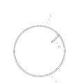
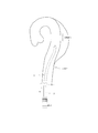
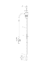
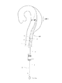
- FIG. 1 is a perspective view showing a configuration of a stent according to Embodiment 1 of the present invention.
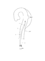
- FIG. 2 is a side view showing the configuration of the stent according to Embodiment 1 of the present invention.
- FIG. 3 is an end view showing the configuration of the stent according to the first embodiment of the present invention as seen from the direction of arrow A in FIG. 1.
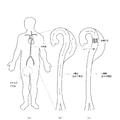
- FIG. 4 is a diagram for explaining an aortic dissection and a treatment method thereof.
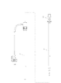
- FIG. 5 is an exploded side view showing a catheter introducer used to place the stent in Embodiment 1 of the present invention at a treatment site in a living body lumen.
- FIG. 1 is a perspective view showing a configuration of a stent according to Embodiment 1 of the present invention.
- FIG. 2 is a side view showing the configuration of the stent according to Embodiment 1 of the present invention.
- FIG. 3 is an end view showing the configuration of the stent according to the first
- FIG. 6 is a side view showing a catheter introducer used to place the stent in Embodiment 1 of the present invention at a treatment site in a living body lumen.
- FIG. 7 is a side perspective view showing a state in which the distal end portion of the catheter is made to reach the vicinity of the treatment site in the in vivo lumen.
- FIG. 8 is a side perspective view showing a state in which the stent according to Embodiment 1 of the present invention is held up to the distal end portion of the catheter using the stent insertion forceps.
- FIG. 9 is a side perspective view showing a state in which the stent according to Embodiment 1 of the present invention is placed at a treatment site in a living body lumen.
- FIG. 9 is a side perspective view showing a state in which the stent according to Embodiment 1 of the present invention is placed at a treatment site in a living body lumen.
- FIG. 10 is a side perspective view showing a state in which the catheter introducer is removed after the stent according to Embodiment 1 of the present invention is placed at a treatment site in a living body lumen.
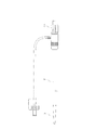
- FIG. 11 is a side perspective view showing a configuration of a recovery snare used for recovering the stent according to the first embodiment of the present invention.
- FIG. 12 is a side perspective view showing a state in which an operation wire, which is a constituent member of the recovery snare of FIG. 11, is inserted into a catheter that is a hollow flexible tube so as to be able to advance and retract.
- FIG. 13 is a side perspective view showing a state where the recovery snare of FIG.
- FIG. 11 is arranged inside a catheter that is a hollow flexible tube and the distal end of the catheter reaches the vicinity of the treatment site.
- 14 is a side perspective view showing a state in which the snare wire, which is a constituent member of the recovery snare of FIG. 11, is pushed out from the distal end of the catheter in the state of FIG.
- FIG. 15 is a side perspective view showing a state in which a snare wire that is a constituent member of the recovery snare of FIG. 11 is hooked on the stent according to the first embodiment of the present invention.
- FIG. 16 is an enlarged view of a two-dot chain line circle portion I in FIG. FIG.
- FIG. 17 is a side perspective view showing a state in which the stent according to Embodiment 1 of the present invention is drawn into the inside of a catheter that is a hollow flexible tube using the recovery snare of FIG. 18 is a side perspective view showing a state where the stent is pulled out after the stent in Embodiment 1 of the present invention is drawn into the inside of the catheter which is a hollow flexible tube using the recovery snare of FIG. It is.
- FIG. 19 is a perspective view showing another configuration of the stent according to Embodiment 1 of the present invention.
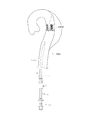
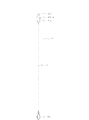
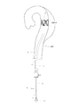
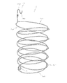
- FIG. 20 is a perspective view showing a configuration of a stent according to Embodiment 2 of the present invention.
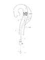
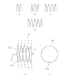
- FIG. 21 is a perspective view showing a configuration of a stent according to Embodiment 3 of the present invention.
- 22 (a) to 22 (d) are schematic views showing the pulse shape of the stent according to Embodiment 3 of the present invention, and
- FIG. 22 (e) is a side view showing the configuration of the stent according to Embodiment 3 of the present invention.
- 22 (f) is a view of the stent according to Embodiment 3 of the present invention as viewed from the end in the longitudinal direction.
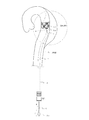
- FIG. 23 is a perspective view showing a configuration of a stent according to Embodiment 4 of the present invention.
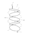
- FIG. 24 is a perspective view showing a configuration of a stent according to Embodiment 5 of the present invention.
- FIG. 25 (a) to 25 (d) are schematic views showing the zigzag shape of the stent according to the fifth embodiment of the present invention.
- FIG. 25 (e) is a side view showing the configuration of the stent according to the fifth embodiment of the present invention.
- 25 (f) is a view of the stent according to the fifth embodiment of the present invention as viewed from the end in the longitudinal direction.
- FIG. 26 is a perspective view showing a configuration of a stent according to Embodiment 6 of the present invention.
- the stent 1 shown in FIGS. 1 to 3 is delivered through the inside of a catheter 2 (see FIGS. 5 and 6), which is a hollow flexible tube, from the base of the incised thigh of the patient.
- the stent 1 is a coil-shaped (spiral) member that supports the inner wall of the in-vivo lumen from the inside in a state where it is placed at a treatment site in the in-vivo lumen (see FIG. 4).
- the stent 1 takes a long and narrow shape along the inside of the catheter 2 by being pulled in the longitudinal direction, and a wound coil capable of supporting the inner wall of the living body lumen from the inside by releasing and releasing the tensile force in the longitudinal direction. It is configured to take a shape (support shape).
- the stent 1 includes a hook portion 1b for collection at one end. That is, the stent 1 of the present embodiment is configured such that the hook portion 1b is formed at one end of the stent, and the coil shape is formed by winding the hook portion 1b as a starting point in the state of the support shape. .
- the position of the hook portion 1b may be either the distal end or the proximal end of the stent 1. Then, the hook 1b is hooked with the recovery snare 4 (see FIGS. 11 and 12) and pulled into the catheter 2, so that the stent 1 is retracted from the coil 2 while being deformed from a coil shape to an elongated shape. It can be recovered in vitro.
- the stent 1 of the present embodiment since it is configured to take an elongated shape along the inside of the catheter 2 by being pulled in the longitudinal direction, it is easy to pass through the inside of the catheter 2 and is delivered to the treatment site. Easy to be.
- it is configured to take a coiled coil shape (support shape) that can support the inner wall of the body lumen from the inside by releasing it. It can play the original role of stent such as support.
- the support shape is a coil shape, the inner wall of the in-vivo lumen can be supported almost uniformly from the inside.
- the inner wall of the living body lumen is placed in a state of being placed in the living body lumen.
- the inner wall of the in-vivo lumen can be sufficiently supported from the inside, and can be easily recovered outside the living body after completing the role. .
- the stent 1 includes a coil-shaped stent body 1a and a hook portion 1b provided at one end of the stent body 1a and formed by bending one end of the coil. Yes.
- the hook portion 1b is positioned on the radially inner side of the outer periphery of the stent body 1a when the stent body 1a has a wound coil shape capable of supporting the inner wall of the living body lumen from the inside. . According to such a configuration, the hook 1b does not damage the inner wall of the in-vivo lumen during treatment.
- the hook portion 1b is provided at the distal end of the coil-shaped stent body 1a and protrudes radially inward in a state of extending from the distal end toward the proximal end.
- the “gripping portion” shown in FIG. 1 is a portion that is gripped by a stent insertion forceps, which will be described later, when the stent 1 is placed at a treatment site in a living body lumen. Note that the position of the gripping portion is not limited to the position shown in FIG. For example, the hook portion 1b may be used as the grip portion.
- the stent 1 is composed of a single wire having a circular shape made of a shape memory alloy, takes an elongated shape along the inside of the catheter 2 when cooled to a temperature lower than the body temperature, and is in vivo when heated to the body temperature. It is configured to take a wound coil shape that can support the inner wall of the lumen from the inside. According to such a configuration, since it is made of a shape memory alloy, sufficient strength can be maintained even if the thickness (thickness) is reduced. And by reducing the thickness (thickness) in this way, it becomes difficult for thrombus to adhere.
- the catheter 2 since it is comprised so that it may take the elongate shape along the inside of the catheter 2 when it cools to the temperature below body temperature, it is easy to pass through the inside of the catheter 2 and to be easily delivered to a treatment site.
- it is configured to take a coiled coil shape that can support the inner wall of the in vivo lumen from the inside when it is heated to body temperature after being delivered to the treatment site. It can play the original role of stent such as support.
- it is configured to take an elongated shape along the inside of the catheter 2 when cooled to a temperature lower than the body temperature.
- the hook portion 1b of the coil-shaped stent 1 supporting the inner wall of the living body lumen from the inside while being placed in the living body lumen is hooked by the recovery snare 4 and pulled into the catheter 2.
- the recovery snare 4 is hooked by the recovery snare 4 and pulled into the catheter 2.
- the outer diameter of the coil when the stent 1 takes the coil shape is preferably 30 to 55 mm, which is substantially the same as the inner diameter of the aorta, which is a lumen in the living body. According to such a preferable configuration, when placed in the aorta for the treatment of aortic dissection, an appropriate tension can be applied to the inner wall of the blood vessel, and no excessive tension is applied. Healing can be promoted appropriately. In this case, it is preferable that the outer diameter of the coil when the stent 1 takes a coil shape changes in the longitudinal direction.
- the outer diameter of the coil can be set in accordance with the change in the inner diameter of the indwelling site, and appropriate treatment can be performed. For example, even when the inner diameter of the in-vivo lumen is partially increased, the coil can be firmly supported. Further, even when the inner diameter of the in-vivo lumen is partially reduced, it is possible to prevent excessive tension from being applied.
- the wire diameter of the wire is preferably 0.3 to 0.7 mm, particularly preferably 0.4 to 0.6 mm. According to such a preferable configuration, adhesion of a thrombus can be effectively suppressed while maintaining the strength of the stent 1.
- the wire diameter is less than 0.3 mm, the wire may bite into the inner wall of the artery and damage the artery.
- the wire diameter exceeds 0.7 mm it is difficult to make it into an elongated shape and insert it into the catheter, and it is difficult to handle such as increased friction in the catheter.
- the tensile strength of the wire is preferably 900 to 1500 MPa, and particularly preferably 1000 to 1200 MPa. According to such a preferable configuration, it is possible to apply an appropriate tension to the inner wall of the living body lumen while maintaining the strength of the stent 1. If the tensile strength is less than 900 MPa, the force pushing the inner wall of the artery is weak, and the dissociated part cannot be sufficiently restored to the normal state. When the tensile strength exceeds 1500 MPa, excessive tension is applied, and there are cases where the blood vessel shape does not follow or the indwelling position cannot be adjusted.
- the material of the stent 1 is preferably any one of nickel titanium alloy, stainless steel, titanium and titanium alloy, for example. According to such a preferable configuration, it is possible to realize a stent that satisfies the conditions of biocompatibility and hardly undergoes deformation such as crushing or folding even when it passes through the thin catheter 2.
- As stainless steel SUS304 and SUS316L are preferable. SUS304 is readily available and relatively inexpensive. SUS316L has the best corrosion resistance among stainless steels.
- the biocompatibility of the stent 1 can be improved. Also, the frictional force between the stent 1 at the time of stent delivery and the inner wall of the living body lumen is made appropriate, the coil pitch of the stent 1 at the time of stent placement is made an appropriate value, and the inner wall of the living body lumen is made appropriate from the inside. Can be supported.
- the thickness of the resin layer is preferably 0.01 to 3.00 mm. By setting the thickness to 0.01 mm or more, the risk of breakage can be reduced without being too thin. By setting the thickness to 3.00 mm or less, the adhesion of thrombus can be effectively suppressed without being too thick.
- the material of the resin layer is preferably, for example, any one of PU (polyurethane), PA (polyamide), PP (polypropylene), PE (polyethylene), and fluororesin. According to such a preferable configuration, there is biocompatibility, and after being inserted into a lumen in a living body, side effects on the human body can be minimized without corrosion.
- the resin layer is not limited to one type.
- the entire wire is covered with a resin such as PU (polyurethane) that has a high frictional force with the lumen in the living body, and a fluororesin that has a low frictional force with the lumen in the living body and does not adhere to the thrombus is applied to the inner part of the coil. Only the coating may be applied. Thereby, it is easy to place the stent 1 at an appropriate position in the lumen of the living body, and thrombus adhesion can be effectively suppressed.
- a drug is applied to the surface of the stent 1. According to such a preferable configuration, healing of the treatment site after placement of the stent 1 can be effectively promoted.
- the drug is preferably a physiologically active substance, and particularly preferably a cell repair agent, anti-inflammatory agent or anticancer agent.
- statin for example, statin, rapamycin, aspirin, dipyridamole, heparin, antithrombin preparation, antiplatelet drugs such as fish oil, low molecular weight heparin, angiotensin converting enzyme inhibitor and other smooth muscle growth inhibitors, vincristine sulfate, vinblastine sulfate Vindecine sulfate, irinotecan hydrochloride, paclitaxel, docetaxel hydrate, methotrexate, cyclophosphamide and other anticancer agents, mitomycin C and other antibiotics, sirolimus, tacrolimus hydrate and other anti-inflammatory agents, steroids and other anti-inflammatory agents, Lipid improving drugs such as atorvastatin calcium and lovastatin, plasmid DNA, gene, siRNA, vertical nucleic acid medicine (decoy), polynucleotide, oligonucleotide, antisense oligonucleotide, ribozyme,
- the drug applied to the surface of the stent 1 is not limited to these substances.
- only one of the above-mentioned physiologically active substances may be applied.
- the synergistic effect of each component is expected to promote the medicinal effect. it can.
- the aorta has a three-layer structure of the outer membrane, the middle membrane, and the inner membrane, and has sufficient strength and elasticity. However, for some reason, a tear (entry part) may be formed in the inner intima, and blood may flow into the outer intima and the aorta may be torn in the long axis direction (FIGS. 4A and 4B). )). Although this is referred to as “aortic dissection”, as a method for treating aortic dissection, a technique of temporarily placing a stent in a blood vessel has been proposed (see FIG. 4C).
- ⁇ Stent placement method The placement of the stent is performed while confirming with angiography.
- a catheter introducer and stent insertion forceps (not shown) shown in FIGS. 5 and 6 are used.
- the catheter introducer shown in FIGS. 5 and 6 includes a catheter 2 that is a hollow flexible tube, and a dilator 3 that is inserted into the catheter 2 from its proximal end.
- the dilator hub 3a comes into contact with the proximal end surface of the catheter 2, the distal end portion of the dilator 3 projects from the distal end of the catheter 2 (state shown in FIG. 6).
- the stent insertion forceps are used together with the catheter 2 which is a constituent member of the catheter introducer.
- the catheter 2 is inserted into the blood vessel from the base of the thigh that has been incised by the patient (see arrow B in FIG. 7), and the distal end portion of the treatment site of the aorta is inserted. Take it to the vicinity.
- the proximal end portion of the catheter 2 is grasped with the left hand, the grasping portion (see FIG. 1) of the stent 1 is grasped with the forceps for stent insertion held with the right hand, and the stent 1 is Insert from the base end face of 2.
- the stent 1 advances inside the catheter 2 while being deformed from a coil shape to an elongated shape (see arrow M in FIG. 8), and reaches the distal end portion of the catheter 2.
- the stent insertion forceps are removed from the catheter 2.
- the proximal end of the catheter 2 is grasped with the left hand, the dilator hub 3a is held with the right hand, and the dilator 3 is inserted into the catheter 2 from the proximal end (the arrow in FIG. 9). See C).
- the catheter 1 is pushed out from the distal end of the catheter 2 by the dilator 3 while being pulled out little by little while rotating the catheter 2 in the same direction as the coil winding direction of the stent 1.
- the stent 1 is heated to the body temperature to become a coil shape, and supports the inner wall of the in-vivo lumen from the inside while being placed in the treatment site in the aorta.
- the catheter introducer (catheter 2 and dilator 3) is removed from the base of the incised thigh of the patient (see arrow D in FIG. 10).
- the placement operation of the stent 1 used for the treatment of aortic dissection is completed.
- ⁇ Stent collection method> The stent 1 that has finished its role after the treatment site is completely cured is collected as follows. This collection operation is also performed while confirming with angiography. Further, the recovery snare 4 and the catheter 2 that is a hollow flexible tube shown in FIGS. 11 and 12 are used for recovery of the stent.
- the recovery snare 4 includes an operation wire 5 and a snare wire 6.
- the operation wire 5 is inserted into the inside of the catheter 2 which is a hollow flexible tube so as to be able to advance and retreat (see a double arrow E in FIG. 12).
- An operation ring 5a is formed at the proximal end of the operation wire 5, and the operation wire 5 can be moved forward and backward or rotated inside the catheter 2 by holding the operation ring 5a (double arrows E, FIG. 12). See F).
- the snare wire 6 is provided at the tip of the operation wire 5.
- the snare wire 6 is made of a single wire, and in a natural state where no external force is applied, the proximal end side first loop portion 6a, the distal end side second loop portion 6b, the first loop portion 6a, and the second loop portion 6b. Is formed in a double loop shape.
- the snare wire 6 is made of a shape-memory alloy wire, and when it is pushed out from the distal end of the catheter 2 in the lumen and heated to body temperature, the first loop portion 6a and the second loop portion 6b come close to each other and are substantially concentric. It can be made to take the shape arranged in a shape.
- the operation wire 5 is made of a stranded wire obtained by twisting a plurality of metal wires such as stainless steel.
- the catheter 2 is inserted into the blood vessel from the base of the incised thigh (see the arrow in FIG. 13). G)) and bring the tip to the vicinity of the treatment site of the aorta.
- the proximal end of the catheter 2 is grasped with the left hand, and the operation wire 5 is advanced by holding the operation ring 5a at the proximal end of the operation wire 5 with the right hand (FIG. 13). , See the arrow H in FIG. 14), and the snare wire 6 is pushed out from the distal end of the catheter 2.
- the snare wire 6 is heated to a body temperature, and has a shape in which the first loop portion 6a and the second loop portion 6b are adjacent to each other and are arranged substantially concentrically.
- the snare wire 6 is hooked on the hook portion 1b (see FIGS. 1 to 3) of the stent 1 while the operation wire 5 is advanced and retracted (see the double arrow J in FIG. 15).
- the snare wire 6 is made of a single wire, and includes a first loop portion 6a on the proximal end side, a second loop portion 6b on the distal end side, and an intersection 6c between the first loop portion 6a and the second loop portion 6b. It is formed in a double loop shape.
- the hook portion 1b of the stent 1 may be hooked on at least one of the first and second loop portions 6a and 6b. Therefore, the snare wire 6 can be easily hooked on the hook portion 1b of the stent 1 without requiring a skilled technique.
- the proximal end of the catheter 2 is grasped with the left hand, and the operation wire 5 is retracted by holding the operation ring 5a at the proximal end of the operation wire 5 with the right hand (FIG. 15).
- the stent 1 is drawn into the catheter 2.
- the catheter 2 is removed from the base of the incised thigh of the patient (see arrow L in FIG. 18). This completes the recovery operation of the stent 1 used for the treatment of aortic dissection.
- the catheter 2 is used as a hollow flexible tube
- the present invention is not necessarily limited to such a configuration.
- a sheath can be used as the hollow flexible tube.
- the stent 1 is made of a shape memory alloy wire
- the stent of the present invention may be made of a wire made of a superelastic alloy such as stainless steel (SUS304) or a Ni—Ti alloy.
- SUS304 stainless steel
- Ni—Ti alloy Ni—Ti alloy
- the stent 1 is made of a wire having a circular cross section.
- the wire may have an irregular cross section such as a flat wire.
- the hook part 1b becomes the coiled coil shape in which the stent main body 1a can support the inner wall of the living body lumen from the inner side, it is radially inward from the outer periphery of the stent main body 1a.
- the hook portion 1b protrudes outward in the longitudinal direction when, for example, the stent body 1a has a wound coil shape capable of supporting the inner wall of the living body lumen from the inside. It may be made like.
- the hook part 1b may be the shape which provided the two curved parts 1b1 and 1b2.
- the two curved portions 1b1 and 1b2 are curved in opposite directions in the longitudinal direction.
- the stent 1 is used for treatment of aortic dissection.
- the stent of the present invention is not necessarily limited to such applications.
- the stent of the present invention is inserted and placed in other blood vessels such as coronary artery, peripheral blood vessel, carotid artery, cerebral artery, vein, trachea, esophagus, large intestine, small intestine, duodenum, ureter, urethra, bile duct, etc. Can be used.
- the hook portion 1b is formed at one end of the stent, and the stent 1 having a coil shape wound around the hook portion 1b in the support shape is described as an example. did.
- the stent of the present invention is not necessarily limited to such a configuration.
- another embodiment of the stent of the present invention will be described with reference to FIGS.
- the following embodiment differs from the first embodiment only in the configuration of the stent in a support shape, and the stent material, wire diameter, etc. and the placement / recovery method are the same as in the first embodiment. . For this reason, the detailed description about these same matters is omitted.
- the stent 7 shown in FIG. 20 is delivered through the inside of the catheter 2 (see FIGS. 5 and 6), which is a hollow flexible tube, from the base of the thigh opened by the patient.
- the stent 7 is a member having a support shape capable of supporting the inner wall of the in-vivo lumen from the inside in a state where it is placed at a treatment site in the in-vivo lumen (see FIG. 4).
- the stent 7 takes an elongated shape along the inside of the catheter 2 by being pulled in the longitudinal direction, and takes a support shape capable of supporting the inner wall of the living body lumen from the inside by releasing and releasing the tensile force in the longitudinal direction. It is configured as follows. Further, the stent 7 includes a recovery hook portion 7b at one end.
- the stent 7 of the present embodiment has a hook portion 7b formed at one end, and in a state of taking a support shape, the first spiral shape portion 7a1, the folded portion 7c, and the second spiral shape portion. 7a2.
- the first spiral portion 7a1 extends from the hook portion 7b in a first spiral shape.
- the folded portion 7c is formed at the end of the first spiral-shaped portion 7a1 opposite to the hook portion 7b.
- the second spiral shape portion 7a2 extends from the folded portion 7c in a second spiral shape wound in the direction opposite to the first spiral shape, and is connected to the hook portion 7b.
- the hook portion 7b has a shape including two curved portions 7b1 and 7b2 that are curved in opposite directions.
- the stent 7 retreats inside the catheter 2 while being deformed from a support shape to an elongated shape. It can be recovered in vitro.
- the hook portion 7b has a shape including two curved portions 7b1 and 7b2 that are curved in opposite directions. Therefore, when the stent 7 is recovered from either the thigh side or the clavicle side, Can be easily recovered.
- the inner wall of the in-vivo lumen can be sufficiently supported from the inside, and the role is finished. It can be easily recovered later in vitro. Furthermore, according to the configuration of the stent 7 of the present embodiment, the inner wall of the in-vivo lumen can be more evenly supported from the inside by the two spiral-shaped portions 7a1 and 7a2.
- the hook portion 7b used as the shape provided with the two curved parts 7b1 and 7b2 curved in the mutually opposite direction was mentioned as an example, and was demonstrated.
- the hook portion may have a shape curved in only one direction.
- the hook portion is positioned radially inward of the outer periphery of the stent 7 when the stent 7 has a support shape capable of supporting the inner wall of the in-vivo lumen from the inside. It may be made to do.
- the stent 8 shown in FIGS. 21, 22 (e), and (f) is delivered through the inside of the catheter 2 (see FIGS. 5 and 6), which is a hollow flexible tube, from the base of the thigh that is incised by the patient.
- the stent 8 is a member having a support shape that can support the inner wall of the in-vivo lumen from the inside in a state where it is placed at a treatment site in the in-vivo lumen (see FIG. 4).
- the stent 8 takes an elongated shape along the inside of the catheter 2 by being pulled in the longitudinal direction, and takes a support shape capable of supporting the inner wall of the living body lumen from the inside by releasing and releasing the tensile force in the longitudinal direction. It is configured as follows. Further, the stent 7 includes a recovery hook portion 8b at one end.
- the stent 8 of the present embodiment has a hook portion 8b formed at one end, and in a state of taking a support shape, the first pulse shape portion 8a1, the folded portion 8c, and the second pulse shape portion. It is comprised so that it may become a shape provided with 8a2.
- the first pulse shape portion 8a1 extends from the hook portion 8b in the first pulse shape in the longitudinal direction, and has a substantially semicircular shape when viewed from the end portion in the longitudinal direction.
- the folded portion 8c is formed at the end of the first pulse shape portion 8a1 opposite to the hook portion 8b.
- the second pulse shape portion 8a2 extends from the folded portion 8c toward the hook portion 8b in a second pulse shape that is substantially plane-symmetric with the first pulse shape, and is connected to the hook portion 8b.
- the hook portion 8b has a shape curved in only one direction.
- the first pulse shape portion 8a1 includes a first semicircular shape portion 9, a first longitudinal shape portion 10, a second semicircular shape portion 11, and a second longitudinal shape portion 12.
- the first semicircular portion 9 extends in a semicircular shape in the circumferential direction from the hook portion 8b.
- the first longitudinal shape portion 10 extends in the longitudinal direction from the end of the first semicircular shape portion 9 opposite to the hook portion 8b.
- the second semicircular portion 11 has a semicircular shape substantially parallel to the first semicircular shape portion 9 from the end of the first longitudinal shape portion 10 opposite to the first semicircular shape portion 9. Extend.
- the second longitudinal shape portion 12 extends in the longitudinal direction from the end of the second semicircular shape portion 11 opposite to the first longitudinal shape portion 10.
- the second pulse shape portion 8a2 has a basic pulse shape portion composed of a third semicircular shape portion 13, a third long shape portion 14, a fourth semicircular shape portion 15, and a fourth long shape portion 16. It has four consecutive configurations.
- the third semicircular portion 13 extends in a semicircular shape that is line-symmetric with the second semicircular portion 11 from the folded portion 8c.
- the third longitudinal shape portion 14 extends substantially in parallel with the first longitudinal shape portion 10 from the end of the third semicircular shape portion 13 on the side opposite to the folded portion 8c.
- the fourth semicircular portion 15 has a semicircular shape that is symmetrical with the first semicircular shape portion 9 from the end of the third longitudinal shape portion 14 opposite to the third semicircular shape portion 13. Extend.
- the fourth longitudinal shape portion 16 extends substantially in parallel with the second longitudinal shape portion 12 from the end of the fourth semicircular shape portion 15 on the opposite side to the third longitudinal shape portion 14.
- the shape of the bent part of the semicircular shape portion and the longitudinal shape portion is a rounded R shape, and the stent 8 does not damage the inner wall of the living body lumen during the treatment.
- various repetitive shapes as shown in FIGS. 22A to 22D can be employed.
- the stent 8 retracts inside the catheter 2 while deforming from a support shape to an elongated shape. It can be recovered in vitro.
- the stent 8 of the present embodiment it is less likely to lie down in the longitudinal direction when or after placement at a treatment site in a living body lumen as compared with a coil-shaped one. Moreover, since the direction of the wire which comprises the stent 8 is not one direction, it is hard to slip in a living body lumen and it is hard to raise
- the hook portion 8b of the shape curved only in one direction was mentioned as an example, and was demonstrated.
- the hook portion may have a shape including two curved portions that are curved in opposite directions, for example, as in the case of the second embodiment.
- the hook portion is positioned radially inward of the outer periphery of the stent 8 when the stent 8 has a support shape capable of supporting the inner wall of the in-vivo lumen from the inside. It may be made to do.
- Embodiment 4 Next, the configuration of the stent according to Embodiment 4 of the present invention will be described with reference to FIG.
- the stent of the present embodiment is different from the third embodiment only in that the pulse shape portions adjacent in the circumferential direction are engaged in an intersecting state, and the other configurations are the same as in the third embodiment. Same as 3. For this reason, the same reference numerals are given to the same members as those in the third embodiment, and detailed description thereof will be omitted.
- pulse-shaped portions adjacent in the circumferential direction are engaged in a crossed state (cross-engagement). That is, the first longitudinal shape portion 10 and the third longitudinal shape portion 14 that are adjacent in the circumferential direction are engaged with each other in an intersecting state. Moreover, the 2nd longitudinal shape part 12 and the 4th longitudinal shape part 16 which adjoin in the circumferential direction are engaged in the state which cross
- This cross-engagement state is, for example, when the second pulse shape portion 8a2 is bent and formed, the third longitudinal shape portion 14 of the second pulse shape portion 8a2 and the like of the first pulse shape portion 8a1. This can be realized by meshing with the longitudinal shape portion 10 and the like.
- the two pulse shape portions 8a1 and 8a2 can be prevented from shifting from each other in the longitudinal direction and the stent 17 can be held in a cylindrical shape.
- the inner wall of the in-vivo lumen can be more reliably supported from the inside.
- the outer diameter of the stent 17 can be matched with the inner diameter of the living body lumen by cross-engaging instead of welding the pulse-shaped portions that are adjacent in the circumferential direction. It becomes possible to firmly support the inner wall of the cavity from the inside.
- the cross-engaging portion bites into the inner wall of the in-vivo lumen, and the stent 17 is tensioned. It is possible to firmly support the inner wall of the inside from the inside.
- the stent 18 shown in FIGS. 24, 25 (e), and (f) is delivered through the inside of the catheter 2 (see FIGS. 5 and 6), which is a hollow flexible tube, from the base of the incised thigh of the patient.
- the stent 18 is a member having a support shape capable of supporting the inner wall of the in-vivo lumen from the inside in a state where it is placed at a treatment site in the in-vivo lumen (see FIG. 4).
- the stent 18 takes an elongated shape along the inside of the catheter 2 by being pulled in the longitudinal direction, and takes a support shape capable of supporting the inner wall of the living body lumen from the inside by releasing and releasing the tensile force in the longitudinal direction. It is configured as follows. Further, the stent 18 includes a recovery hook portion 18b at one end.
- the stent 18 of the present embodiment has a hook portion 18b formed at one end, and in a state of taking a support shape, the first zigzag shape portion 18a1, the folded portion 18c, and the second zigzag shape portion. It is comprised so that it may become a shape provided with 18a2.
- the first zigzag-shaped portion 18a1 extends in a first zigzag shape in the longitudinal direction from the hook portion 18b, and has a substantially semicircular shape when viewed from the end in the longitudinal direction.
- the folded portion 18c is formed at the end of the first zigzag shaped portion 18a1 on the opposite side to the hook portion 18b.
- the second zigzag portion 18a2 extends from the folded portion 18c toward the hook portion 18b in a second zigzag shape that is substantially plane symmetric with the first zigzag shape, and is connected to the hook portion 18b.
- the hook portion 18b has a shape curved in only one direction.
- the first zigzag portion 18a1 includes the first semicircular portion 19, the first R shape portion 20, the second semicircular shape portion 21, the second R shape portion 22, and the third.
- the first semicircular portion 19 extends in a semicircular shape in an oblique circumferential direction from the hook portion 18b.
- the first R-shaped portion 20 is folded back from the end of the first semicircular-shaped portion 19 opposite to the hook portion 18b.
- the second semicircular portion 21 is a semicircular shape that is substantially plane-symmetric with the first semicircular portion 19 from the end of the first R-shaped portion 20 opposite to the first semicircular portion 19.
- the second R-shaped part 22 is folded back from the end of the second semicircular shaped part 21 opposite to the first R-shaped part 20.
- the third semicircular portion 23 is a semicircular shape that is substantially parallel to the first semicircular portion 19 from the end opposite to the second semicircular portion 21 of the second R-shaped portion 22.
- the third R-shaped part 24 is folded back from the end of the third semicircular shaped part 23 opposite to the second R-shaped part 22.
- the fourth semicircular portion 25 is a semicircular shape that is substantially parallel to the second semicircular portion 21 from the end opposite to the third semicircular portion 23 of the third R-shaped portion 24. Extend.
- the fourth R-shaped portion 26 is folded back from the end of the fourth semicircular shaped portion 25 opposite to the third R-shaped portion 24.
- the fifth semicircular portion 27 has a semicircular shape substantially parallel to the third semicircular portion 23 from the end opposite to the fourth semicircular portion 25 of the fourth R-shaped portion 26. Extend.
- the second zigzag portion 18a2 includes a sixth semicircular portion 28, a sixth R shape portion 29, a seventh semicircular shape portion 30, a seventh R shape portion 31, and an eighth semicircular shape portion. 32, an eighth R-shaped portion 33, a ninth semicircular shaped portion 34, a ninth R-shaped portion 35, and a tenth semicircular shaped portion 36.
- the sixth semicircular portion 28 extends in a semicircular shape that is substantially plane-symmetric with the fifth semicircular portion 27 from the folded portion 18c.
- the sixth R-shaped part 29 is folded back from the end of the sixth semicircular shaped part 28 opposite to the folded part 18c.
- the seventh semicircular portion 30 has a semicircular shape that is substantially plane-symmetric with the fourth semicircular portion 25 from the end of the sixth R-shaped portion 29 opposite to the sixth semicircular portion 28. Extend.
- the seventh R-shaped part 31 is folded back from the end of the seventh semicircular shaped part 30 opposite to the sixth R-shaped part 29.
- the eighth semicircular portion 32 has a semicircular shape that is substantially plane-symmetric with the third semicircular portion 23 from the end of the seventh R-shaped portion 31 opposite to the seventh semicircular portion 30. Extend.
- the eighth R-shaped portion 33 is folded back from the end of the eighth semicircular shaped portion 32 opposite to the seventh R-shaped portion 31.
- the ninth semicircular portion 34 is a semicircular shape that is substantially plane-symmetric with the second semicircular portion 21 from the end of the eighth R-shaped portion 33 opposite to the eighth semicircular portion 32. Extend.
- the ninth R-shaped portion 35 is folded back from the end of the ninth semicircular shaped portion 34 opposite to the eighth R-shaped portion 33.
- the tenth semicircular portion 36 is a semicircular shape that is substantially plane-symmetric with the first semicircular portion 19 from the end of the ninth R-shaped portion 35 opposite to the ninth semicircular portion 34. Extend.
- the stent 18 of this embodiment has a rounded shape as a whole, and the stent 18 does not damage the inner wall of the in-vivo lumen during treatment.
- the first and second zigzag shapes those having various repeated shapes as shown in FIGS. 25A to 25D can be adopted.
- the stent 8 is retracted from the support shape while being deformed from a support shape to an elongated shape. It can be recovered in vitro.
- the stent 18 of the present embodiment it is less likely to fall down in the longitudinal direction when or after being placed at a treatment site in a living body lumen as compared with a coil shape. Moreover, since the direction of the wire which comprises the stent 18 is not one direction, it is hard to slip in a living body lumen and it is hard to raise
- the hook portion may have a shape including two curved portions that are curved in opposite directions, for example, as in the case of the second embodiment.
- the hook portion is positioned radially inward from the outer periphery of the stent 18 when the stent 18 has a support shape capable of supporting the inner wall of the in-vivo lumen from the inside. It may be made to do.
- the configuration of the stent according to Embodiment 6 of the present invention will be described with reference to FIG.
- the stent of this embodiment differs from the said Embodiment 5 only in the point where the zigzag-shaped parts which adjoin in the circumferential direction are engaged in the state which cross
- the stent 37 shown in FIG. 26 is engaged in a state where zigzag portions adjacent in the circumferential direction intersect each other (cross engagement). That is, the first R-shaped portion 20 and the ninth R-shaped portion 35 that are adjacent in the circumferential direction are engaged with each other in an intersecting state. Further, the second R-shaped portion 22 and the eighth R-shaped portion 33 which are adjacent in the circumferential direction are engaged with each other in an intersecting state. Further, the third R-shaped portion 24 and the seventh R-shaped portion 31 that are adjacent in the circumferential direction are engaged with each other in an intersecting state. Further, the fourth R-shaped portion 26 and the sixth R-shaped portion 29 which are adjacent in the circumferential direction are engaged with each other in an intersecting state.
- This cross-engagement state is, for example, in the stage where the second zigzag shape portion 18a2 is bent and formed, the sixth R shape portion 29, the seventh R shape portion 31 and the eighth shape of the second zigzag shape portion 18a2.
- the R-shaped part 33 and the ninth R-shaped part 35 are sequentially connected to the fourth R-shaped part 26, the third R-shaped part 24, the second R-shaped part 22 and the first zigzag-shaped part 18a1, respectively. This can be realized by netting into one R-shaped portion 20.
- the two zigzag-shaped portions 18a1 and 18a2 can be prevented from shifting from each other in the longitudinal direction and the stent 37 can be held in a cylindrical shape.
- the inner wall of the in-vivo lumen can be more reliably supported from the inside. Since the zigzag-shaped portions that are adjacent in the circumferential direction are cross-engaged instead of welded in this way, the outer diameter of the stent 37 can be matched with the inner diameter of the in-vivo lumen. It becomes possible to firmly support the inner wall of the cavity from the inside.
- the cross-engaging portion bites into the inner wall of the in-vivo lumen, and the stent 37 is tensioned. It is possible to firmly support the inner wall of the inside from the inside.
Abstract
[Problem] To provide a stent capable of sufficiently supporting an inner wall of an inner cavity in a living body, from inside, and capable of being easily retrieved outside the living body after the use thereof is completed. [Solution] A stent 1 that: is delivered through the interior of a catheter, being a hollow flexible tube, from an incision at the base of the thigh of a patient; and is a coiled shaped (support-shaped) member that supports the inner wall of an inner cavity in a living body, from the inside and in a state in which the stent remains at the treatment site inside the inner cavity in the living body. The stent 1 is configured to have a long narrow shape following the inside of the catheter 2, when pulled in the longitudinal direction, and a coiled shape wound so as to support the inner wall of the inner cavity in the living body, from the inside, when released. The stent 1 also comprises a hooked section 1b for retrieval, at one end thereof.
Description
本発明は、ステントに関する。さらに詳細には、本発明は、生体内管腔の治療に用いられる医療用のステントに関する。
The present invention relates to a stent. More particularly, the present invention relates to a medical stent used for treatment of an in vivo lumen.
大動脈解離は、突然死する疾患であり、病院までたどり着くことができた場合は、治療のほとんどが急を要する緊急手術となる。手術手技も高難度であり、緊急性が高いため、医師や患者にとってとてもストレスが大きい疾患である。従来、例えば大動脈解離等の治療方法として、血管等の生体内管腔内に金属製のステントを留置する方法が知られている(例えば、特許文献1等を参照)。ステントを用いた治療は、開腹手術が不要であるため、低侵襲であるというメリットがある。
しかし、ステントを血管内に長期間留置した場合には、ステントに血栓が付着し、それによって血栓閉塞を引き起こす虞がある。また、治療部位が完治した後にも、役目を終えたステントが異物として体内に残ってしまい、それによって異物反応を引き起こす虞もある。 Aortic dissection is a disease that suddenly dies, and if it can reach the hospital, most of the treatment is an urgent emergency operation. Surgical techniques are also highly difficult and urgent, making it a very stressful disease for doctors and patients. Conventionally, as a method for treating aortic dissection, for example, a method of placing a metal stent in a body lumen such as a blood vessel is known (see, for example, Patent Document 1). Since treatment using a stent does not require laparotomy, there is a merit that it is minimally invasive.
However, when the stent is left in the blood vessel for a long period of time, a thrombus may adhere to the stent, thereby causing a thrombus blockage. In addition, even after the treatment site is completely cured, the stent that has finished its role remains in the body as a foreign substance, which may cause a foreign body reaction.
そこで、従来、例えば特許文献2等に開示されているような、生体内に留置した後に数年で溶けてなくなる生体吸収性ステントが提案されている。
Therefore, conventionally, for example, a bioabsorbable stent has been proposed, which is disclosed in, for example, Patent Document 2 or the like and does not dissolve in several years after being placed in the living body.
しかし、生体吸収性ステントは、金属製のステントと比べて、強度、厚み(太さ)等の点で課題がある。すなわち、厚み(太さ)が大きくなると、強度は保たれるが、血栓が付着しやすくなる。一方、厚み(太さ)が小さくなると、強度が弱くなり、破損の虞が生じる。そして、このように強度が弱くなると、生体内管腔の内壁を内側から十分にサポートすることができない。
However, bioabsorbable stents have problems in terms of strength, thickness (thickness), etc., compared to metal stents. That is, when the thickness (thickness) is increased, the strength is maintained, but the thrombus tends to adhere. On the other hand, when the thickness (thickness) becomes small, the strength becomes weak and there is a risk of breakage. And when intensity | strength becomes weak in this way, the inner wall of a living body lumen cannot fully be supported from an inner side.
そこで、本発明は、大動脈解離等の治療として応急処置に最適な、生体内管腔の内壁を内側から十分にサポートすることができるステントであって、役目を終えた後に生体外に簡単に回収することが可能なステントを提供することを目的とする。
Therefore, the present invention is a stent that can adequately support the inner wall of the in-vivo lumen from the inside, which is optimal for emergency treatment as a treatment for aortic dissection, etc. It is an object of the present invention to provide a stent that can be used.
前記目的を達成するため、本発明に係るステントの構成は、
(1)中空の可撓管の内部を通して送達され、生体内管腔内に留置された状態で前記生体内管腔の内壁を内側からサポートする形状のステントであって、
長手方向に引っ張ることで前記可撓管の内部に沿った細長い形状をとり、放すことで前記生体内管腔の内壁を内側からサポート可能なサポート形状をとるように構成され、
回収用のフック部を備え、前記フック部を回収用スネアで引っ掛けて前記可撓管の内部へ引き込むことで、前記ステントは前記サポート形状から前記細長い形状に変形しながら前記可撓管の内部を後退し、生体外に回収可能であることを特徴とする。 In order to achieve the above object, the configuration of the stent according to the present invention includes:
(1) A stent that is delivered through the inside of a hollow flexible tube and supports the inner wall of the living body lumen from the inside while being placed in the living body lumen,
It is configured to take an elongated shape along the inside of the flexible tube by pulling in the longitudinal direction, and to take a support shape that can support the inner wall of the biological lumen from the inside by releasing,
A recovery hook portion is provided, and the hook portion is hooked with a recovery snare and pulled into the flexible tube, so that the stent is deformed from the support shape to the elongated shape while moving inside the flexible tube. It is retracted and can be recovered outside the living body.
本発明のステントの上記(1)の構成は、次のような作用効果を奏する。すなわち、長手方向に引っ張ることで可撓管の内部に沿った細長い形状をとるように構成されているため、可撓管の内部を通過しやすく、治療部位へ送達されやすい。また、治療部位へ送達された後、放すことで生体内管腔の内壁を内側からサポート可能なサポート形状をとるように構成されているため、血管内壁の内側からのサポート等、ステント本来の役割を果たすことができる。また、上記のように、長手方向に引っ張ることで可撓管の内部に沿った細長い形状をとるように構成されているため、生体内管腔内に留置された状態で生体内管腔の内壁を内側からサポートしているサポート形状のステントのフック部を回収用スネアで引っ掛けて可撓管の内部へ引き込むことで、生体外に簡単に回収することができる。
このように、本発明のステントの上記(1)の構成によれば、生体内管腔の内壁を内側から十分にサポートすることができ、かつ、役目を終えた後に生体外に簡単に回収することができる。 The configuration (1) of the stent of the present invention has the following effects. That is, since it is configured to take an elongated shape along the inside of the flexible tube by pulling in the longitudinal direction, it easily passes through the inside of the flexible tube and is easily delivered to the treatment site. Also, since it is configured to take a support shape that can support the inner wall of the in vivo lumen from the inside after being delivered to the treatment site, the original role of the stent, such as support from the inside of the blood vessel inner wall, etc. Can be fulfilled. In addition, as described above, the inner wall of the in-vivo lumen is placed in the in-vivo lumen because the elongate shape is taken along the inside of the flexible tube by pulling in the longitudinal direction. By hooking the hook portion of the support-shaped stent that supports the tube from the inside with the recovery snare and pulling it into the flexible tube, it can be easily recovered outside the living body.
As described above, according to the configuration of (1) of the stent of the present invention, the inner wall of the in-vivo lumen can be sufficiently supported from the inside, and can be easily recovered outside the in-vivo after finishing the role. be able to.
本発明のステントの上記(1)の構成においては、以下の(2)~(20)のような構成にすることが好ましい。
In the above configuration (1) of the stent of the present invention, the following configurations (2) to (20) are preferable.
(2)前記フック部は、前記ステントの一端に形成されており、
前記サポート形状をとった状態で、
前記フック部を始点として巻回したコイル形状となる。上記(2)の好ましい構成によれば、生体内管腔の内壁を内側からほぼ均等にサポートすることが可能となる。 (2) The hook portion is formed at one end of the stent,
In the state of taking the support shape,
The coil is wound around the hook portion as a starting point. According to the preferable configuration of (2) above, the inner wall of the living body lumen can be supported almost uniformly from the inside.
(3)前記フック部は、前記ステントの一端に形成されており、
前記サポート形状をとった状態で、
前記フック部から第1の螺旋形状で延びる第1の螺旋形状部と、
前記第1の螺旋形状部の、前記フック部と反対側の端に形成された折り返し部と、
前記折り返し部から前記第1の螺旋形状と逆方向に巻回した第2の螺旋形状で延び、前記フック部に連結された第2の螺旋形状部と、を備えた形状となる。上記(3)の好ましい構成によれば、2つの螺旋形状部により、生体内管腔の内壁を内側からさらに均等にサポートすることが可能となる。 (3) The hook portion is formed at one end of the stent,
In the state of taking the support shape,
A first spiral-shaped portion extending in a first spiral shape from the hook portion;
A folded portion formed at an end of the first spiral-shaped portion opposite to the hook portion;
A second spiral shape extending from the folded portion in a second spiral shape wound in the opposite direction to the first spiral shape and connected to the hook portion is provided. According to the preferable configuration of (3) above, the inner wall of the in-vivo lumen can be more evenly supported from the inside by the two spiral-shaped portions.
(4)前記フック部は、前記ステントの一端に形成されており、
前記サポート形状をとった状態で、
前記フック部から長手方向に第1のパルス形状で延びる、長手方向端部から見て略半円形状の第1のパルス形状部と、
前記第1のパルス形状部の、前記フック部と反対側の端に形成された折り返し部と、
前記折り返し部から前記フック部に向かって前記第1のパルス形状と略面対称な第2のパルス形状で延び、前記フック部に連結された第2のパルス形状部と、を備えた形状となる。上記(4)の好ましい構成によれば、生体内管腔内の治療部位に留置する際、あるいは留置した後に、長手方向に横倒れしにくい。また、ステントを構成する線材の方向が一方向ではないため、生体内管腔内で滑りにくく、位置ずれを起こしにくい。さらに、ステントを構成する線材の半円形状部が円周方向に延び、互いに平行であるため、外周からの圧力で潰れにくい。その結果、生体内管腔の内壁を内側から確実にサポートすることが可能となる。 (4) The hook portion is formed at one end of the stent,
In the state of taking the support shape,
A first pulse shape portion extending in a first pulse shape in the longitudinal direction from the hook portion, and having a substantially semicircular shape when viewed from the longitudinal end portion;
A folded portion formed at an end of the first pulse shape portion opposite to the hook portion;
A second pulse shape portion that extends from the folded portion toward the hook portion in a second pulse shape that is substantially plane-symmetric with the first pulse shape and is connected to the hook portion. . According to the preferable configuration of (4) above, it is difficult to fall down in the longitudinal direction when or after placement at the treatment site in the body lumen. In addition, since the direction of the wire constituting the stent is not one direction, it is difficult to slip in the in-vivo lumen, and is not likely to be displaced. Furthermore, since the semicircular portions of the wire constituting the stent extend in the circumferential direction and are parallel to each other, they are not easily crushed by pressure from the outer periphery. As a result, the inner wall of the in-vivo lumen can be reliably supported from the inside.
(5)上記(4)の構成において、円周方向で近接するパルス形状部同士が、交差した状態で係合している(交差係合)。上記(5)の好ましい構成によれば、2つのパルス形状部が長手方向逆向きに互いにずれることを防止して、ステントを円筒形状に保持することができる。その結果、生体内管腔の内壁を内側からさらに確実にサポートすることが可能となる。そして、このように、円周方向で近接するパルス形状部同士を、溶着ではなく交差係合させることで、ステントの外径を生体内管腔の内径に合わせることができるので、生体内管腔の内壁を内側からしっかりとサポートすることが可能となる。特に、ステントの外径よりも生体内管腔の内径が小さい場合には、交差係合部が生体内管腔の内壁に食い込み気味となることでステントにテンションがかかり、生体内管腔の内壁を内側からしっかりとサポートすることができる。
(5) In the configuration of the above (4), the pulse shape portions adjacent in the circumferential direction are engaged in a crossed state (cross-engagement). According to the preferable configuration of (5) above, it is possible to prevent the two pulse-shaped portions from being displaced from each other in the longitudinal direction and to hold the stent in a cylindrical shape. As a result, the inner wall of the in-vivo lumen can be more reliably supported from the inside. And, in this way, the outer diameter of the stent can be matched to the inner diameter of the living body lumen by cross-engaging instead of welding the pulse shape portions that are adjacent in the circumferential direction. It becomes possible to firmly support the inner wall of the inside from the inside. In particular, when the inner diameter of the in-vivo lumen is smaller than the outer diameter of the stent, the cross engagement portion bites into the inner wall of the in-vivo lumen, and the stent is tensioned. Can be firmly supported from the inside.
(6)前記フック部は、前記ステントの一端に形成されており、
前記サポート形状をとった状態で、
前記フック部から長手方向に第1のジグザグ形状で延びる、長手方向端部から見て略半円形状の第1のジグザグ形状部と、
前記第1のジグザグ形状部の、前記フック部と反対側の端に形成された折り返し部と、
前記折り返し部から前記フック部に向かって前記第1のジグザグ形状と略面対称な第2のジグザグ形状で延び、前記フック部に連結された第2のジグザグ形状部と、を備えた形状となる。上記(6)の好ましい構成によれば、コイル形状のものと比較して、生体内管腔内の治療部位に留置する際、あるいは留置した後に、長手方向に横倒れしにくい。また、ステントを構成する線材の方向が一方向ではないため、生体内管腔内で滑りにくく、位置ずれを起こしにくい。さらに、ステントが長手方向にジグザグ形状で延びているため、上記(4)の構成のものよりもさらに横倒れしにくい。その結果、生体内管腔の内壁を内側から確実にサポートすることが可能となる。 (6) The hook portion is formed at one end of the stent,
In the state of taking the support shape,
A first zigzag-shaped portion having a substantially semicircular shape as viewed from the end in the longitudinal direction, extending in a first zigzag shape in the longitudinal direction from the hook portion;
A folded portion formed at an end of the first zigzag-shaped portion opposite to the hook portion;
A second zigzag portion extending from the folded portion toward the hook portion in a second zigzag shape that is substantially plane-symmetric with the first zigzag shape and connected to the hook portion. . According to the preferred configuration of (6) above, it is less likely to lie down in the longitudinal direction when or after placement at the treatment site in the living body lumen as compared with the coil-shaped one. In addition, since the direction of the wire constituting the stent is not one direction, it is difficult to slip in the in-vivo lumen, and is not likely to be displaced. Furthermore, since the stent extends in a zigzag shape in the longitudinal direction, the stent is more unlikely to fall down than the above-described configuration (4). As a result, the inner wall of the in-vivo lumen can be reliably supported from the inside.
(7)上記(6)の構成において、円周方向で近接するジグザグ形状部同士が、交差した状態で係合している(交差係合)。上記(7)の好ましい構成によれば、2つのジグザグ形状部が長手方向逆向きに互いにずれることを防止して、ステントを円筒形状に保持することができる。その結果、生体内管腔の内壁を内側からさらに確実にサポートすることが可能となる。そして、このように、円周方向で近接するジグザグ形状部同士を、溶着ではなく交差係合させることで、ステントの外径を生体内管腔の内径に合わせることができるので、生体内管腔の内壁を内側からしっかりとサポートすることが可能となる。特に、ステントの外径よりも生体内管腔の内径が小さい場合には、交差係合部が生体内管腔の内壁に食い込み気味となることでステントにテンションがかかり、生体内管腔の内壁を内側からしっかりとサポートすることができる。
(7) In the configuration of (6) above, zigzag portions that are adjacent in the circumferential direction are engaged in an intersecting state (cross engagement). According to the preferable configuration of (7) above, it is possible to prevent the two zigzag-shaped portions from shifting from each other in the longitudinal direction and to hold the stent in a cylindrical shape. As a result, the inner wall of the in-vivo lumen can be more reliably supported from the inside. And, since the zigzag-shaped portions adjacent in the circumferential direction are cross-engaged instead of welded in this way, the outer diameter of the stent can be matched to the inner diameter of the in-vivo lumen, so that the in-vivo lumen It becomes possible to firmly support the inner wall of the inside from the inside. In particular, when the inner diameter of the in-vivo lumen is smaller than the outer diameter of the stent, the cross engagement portion bites into the inner wall of the in-vivo lumen, and the stent is tensioned. Can be firmly supported from the inside.
(8)1本の形状記憶合金製の線材からなり、
体温を下回る温度まで冷却されたときに前記可撓管の内部に沿った前記細長い形状をとり、体温まで加熱されたときに前記生体内管腔の内壁を内側からサポート可能な前記サポート形状をとるように構成されている。上記(8)の好ましい構成によれば、形状記憶合金製であるため、厚み(太さ)を小さくしても、十分な強度を維持することができる。そして、このように厚み(太さ)を小さくすることにより、血栓が付着しにくくなる。また、体温を下回る温度まで冷却されたときに可撓管の内部に沿った細長い形状をとるように構成されているため、可撓管の内部を通過しやすく、治療部位へ送達されやすい。また、治療部位へ送達された後、体温まで加熱されたときに生体内管腔の内壁を内側からサポート可能なサポート形状をとるように構成されているため、血管内壁の内側からのサポート等、ステント本来の役割を果たすことができる。また、上記のように、体温を下回る温度まで冷却されたときに可撓管の内部に沿った細長い形状をとるように構成されているため、生体内管腔内に留置された状態で生体内管腔の内壁を内側からサポートしているサポート形状のステントのフック部を回収用スネアで引っ掛けて可撓管の内部へ引き込むことで、生体外に簡単に回収することができる。 (8) It consists of one shape memory alloy wire,
It takes the elongated shape along the inside of the flexible tube when cooled to a temperature below body temperature, and takes the support shape that can support the inner wall of the living body lumen from the inside when heated to body temperature. It is configured as follows. According to the preferable configuration of (8), since it is made of a shape memory alloy, sufficient strength can be maintained even if the thickness (thickness) is reduced. And by reducing the thickness (thickness) in this way, it becomes difficult for thrombus to adhere. Moreover, since it is comprised so that it may take the elongate shape along the inside of a flexible tube when it cools to the temperature below body temperature, it is easy to pass the inside of a flexible tube, and to be easily delivered to a treatment site. In addition, since it is configured to take a support shape that can support the inner wall of the in-vivo lumen from the inside when it is heated to body temperature after being delivered to the treatment site, the support from the inside of the blood vessel inner wall, etc. It can play the original role of the stent. In addition, as described above, since it is configured to take an elongated shape along the inside of the flexible tube when cooled to a temperature lower than the body temperature, By hooking the hook portion of the support-shaped stent that supports the inner wall of the lumen from the inside with the recovery snare and pulling it into the flexible tube, it can be easily recovered outside the living body.
(9)前記フック部は、前記ステントが前記サポート形状となった際に、前記ステントの外周よりも径方向内側に位置する。上記(9)の好ましい構成によれば、ステントがサポート形状となった際に、フック部が径方向内側に位置するようにすることにより、治療中にフック部によって生体内管腔の内壁を傷つけてしまうことはない。
(9) The hook portion is located radially inward from the outer periphery of the stent when the stent has the support shape. According to the preferable configuration of the above (9), when the stent is in the support shape, the hook portion is positioned on the radially inner side, so that the inner wall of the in-vivo lumen is damaged by the hook portion during the treatment. There is no end to it.
(10)前記サポート形状をとるときの前記ステントの外径が、前記生体内管腔である大動脈の内径とほぼ同じ、30~55mmである。上記(10)の好ましい構成によれば、大動脈解離の治療のために大動脈内に留置した際に、血管内壁に適切なテンションをかけることができ、過度なテンションがかかることはないので、大動脈解離のエントリー部の治癒を適切に促進させることができる。
(10) The outer diameter of the stent when taking the support shape is 30 to 55 mm, which is substantially the same as the inner diameter of the aorta that is the lumen in the living body. According to the preferred configuration of (10) above, when placed in the aorta for the treatment of aortic dissection, an appropriate tension can be applied to the inner wall of the blood vessel, and no excessive tension is applied. It is possible to appropriately promote the healing of the entry part.
(11)上記(10)の構成において、前記サポート形状をとるときの前記ステントの外径が、長手方向で変化する。上記(11)の好ましい構成によれば、留置する部位の内径が長手方向で変化する場合にも、留置部位の内径の変化に合わせたステントの外径とすることができ、適切な治療を行うことができる。例えば、部分的に生体内管腔の内径が大きくなる場合にも、しっかりとステントでサポートできる。また、部分的に生体内管腔の内径が小さくなる場合にも、過度なテンションをかけないようにすることができる。
(11) In the configuration of (10) above, the outer diameter of the stent when taking the support shape changes in the longitudinal direction. According to the preferred configuration of (11) above, even when the inner diameter of the site to be placed changes in the longitudinal direction, the outer diameter of the stent can be adjusted in accordance with the change in the inner diameter of the site to be placed, and appropriate treatment is performed. be able to. For example, even when the inner diameter of the in-vivo lumen is partially increased, the stent can be firmly supported. Further, even when the inner diameter of the in-vivo lumen is partially reduced, it is possible to prevent excessive tension from being applied.
(12)上記(8)~(11)のいずれか1つの構成において、前記線材の線径が0.3~0.7mmである。上記(12)の好ましい構成によれば、ステントの強度を維持しつつ、血栓の付着を効果的に抑制することができる。
(12) In any one of the configurations (8) to (11) above, the wire diameter of the wire is 0.3 to 0.7 mm. According to the preferable configuration of (12) above, it is possible to effectively suppress adhesion of thrombus while maintaining the strength of the stent.
(13)上記(8)~(12)のいずれか1つの構成において、前記線材の引張り強さが900~1500MPaである。上記(13)の好ましい構成によれば、ステントの強度を維持しつつ、生体内管腔の内壁に適切なテンションをかけることができる。
(13) In any one of the configurations (8) to (12) above, the tensile strength of the wire is 900 to 1500 MPa. According to the preferable configuration of (13) above, it is possible to apply an appropriate tension to the inner wall of the living body lumen while maintaining the strength of the stent.
(14)上記(8)~(13)のいずれか1つの構成において、前記線材の材質が、ニッケルチタン合金、ステンレス鋼、チタン及びチタン合金のうちのいずれか一つである。上記(14)の好ましい構成によれば、生体適合性の条件を満たし、細径な可撓管内を通過しても潰れや折り癖などの変形が生じ難いステントを実現することができる。
(14) In any one of the configurations (8) to (13), the material of the wire is any one of nickel titanium alloy, stainless steel, titanium, and titanium alloy. According to the preferred configuration of (14), it is possible to realize a stent that satisfies the biocompatibility condition and hardly undergoes deformation such as crushing and folding even when passing through a thin flexible tube.
(15)上記(8)~(14)のいずれか1つの構成において、前記線材の表面に樹脂層を備える。上記(15)の好ましい構成によれば、ステントの生体適合性を向上させることができる。また、ステント送達時のステントと生体内管腔の内壁との間の摩擦力を適切にし、ステント留置時のステントの長手方向のピッチを適切な値にし、生体内管腔の内壁を内側から適切にサポートすることができる。
(15) In any one of the configurations (8) to (14), a resin layer is provided on the surface of the wire. According to the preferable configuration of (15) above, the biocompatibility of the stent can be improved. In addition, the frictional force between the stent during delivery of the stent and the inner wall of the in-vivo lumen is appropriate, the longitudinal pitch of the stent during stent placement is set to an appropriate value, and the inner wall of the in-vivo lumen is adequate from the inside. Can be supported.
(16)上記(15)の構成において、前記樹脂層の厚みが0.01~3.00mmである。厚みを0.01mm以上とすることで、薄すぎることなく、破損の恐れを低減することができる。厚みを3.00mm以下とすることで、厚すぎることなく、血栓の付着を効果的に抑制することができる。
(16) In the configuration of (15), the thickness of the resin layer is 0.01 to 3.00 mm. By setting the thickness to 0.01 mm or more, the risk of breakage can be reduced without being too thin. By setting the thickness to 3.00 mm or less, the adhesion of thrombus can be effectively suppressed without being too thick.
(17)上記(15)又は(16)の構成において、前記樹脂層の材質が、PU(ポリウレタン)、PA(ポリアミド)、PP(ポリプロピレン)、PE(ポリエチレン)及びフッ素樹脂のうちのいずれか一つである。上記(17)の好ましい構成によれば、生体適合性があって、生体内管腔に挿入された後、腐食せず人体への副作用を最少化できる。
(17) In the configuration of (15) or (16), the material of the resin layer is any one of PU (polyurethane), PA (polyamide), PP (polypropylene), PE (polyethylene), and fluororesin. One. According to the preferred configuration of the above (17), there is biocompatibility, and after insertion into a living body lumen, side effects on the human body can be minimized without corrosion.
(18)表面に薬剤が塗布される。上記(18)の好ましい構成によれば、ステントの留置後の治療部位の治癒を効果的に促進することができる。
(18) The drug is applied to the surface. According to the preferred configuration of (18) above, healing of the treatment site after placement of the stent can be effectively promoted.
(19)上記(18)の構成において、前記薬剤が、生理活性物質である。
(19) In the configuration of (18), the drug is a physiologically active substance.
(20)大動脈解離の治療に用いられる。
(20) Used for the treatment of aortic dissection.
本発明によれば、生体内管腔の内壁を内側から十分にサポートすることができ、かつ、役目を終えた後に生体外に簡単に回収することができる。
According to the present invention, the inner wall of the in-vivo lumen can be sufficiently supported from the inside, and can be easily recovered outside the in-vivo after completing the role.
以下、好適な実施形態を用いて本発明をさらに具体的に説明する。但し、下記の実施態は本発明を具現化した例に過ぎず、本発明はこれに限定されるものではない。
Hereinafter, the present invention will be described in more detail using preferred embodiments. However, the following embodiments are merely examples embodying the present invention, and the present invention is not limited thereto.
[実施形態1]
(ステントの構成)
まず、本発明の実施形態1におけるステントの構成について、図1~図3を参照しながら説明する。 [Embodiment 1]
(Stent structure)
First, the configuration of the stent according toEmbodiment 1 of the present invention will be described with reference to FIGS.
(ステントの構成)
まず、本発明の実施形態1におけるステントの構成について、図1~図3を参照しながら説明する。 [Embodiment 1]
(Stent structure)
First, the configuration of the stent according to
図1~図3に示すステント1は、患者の切開した太ももの付け根等から中空の可撓管であるカテーテル2(図5,図6を参照)の内部を通して送達される。ステント1は、生体内管腔内の治療部位に留置された状態で生体内管腔の内壁を内側からサポートするコイル形状(螺旋形状)の部材である(図4を参照)。ステント1は、長手方向に引っ張ることでカテーテル2の内部に沿った細長い形状をとり、長手方向の引張力を解放して放すことで生体内管腔の内壁を内側からサポート可能な巻回したコイル形状(サポート形状)をとるように構成されている。また、ステント1は、一端に回収用のフック部1bを備えている。すなわち、本実施形態のステント1は、フック部1bがステントの一端に形成されており、サポート形状をとった状態で、フック部1bを始点として巻回したコイル形状となるように構成されている。なお、フック部1bの位置は、ステント1の先端、基端のどちらでもよい。
そして、フック部1bを回収用スネア4(図11,図12を参照)で引っ掛けてカテーテル2の内部へ引き込むことで、ステント1はコイル形状から細長い形状に変形しながらカテーテル2の内部を後退し、生体外に回収可能である。 Thestent 1 shown in FIGS. 1 to 3 is delivered through the inside of a catheter 2 (see FIGS. 5 and 6), which is a hollow flexible tube, from the base of the incised thigh of the patient. The stent 1 is a coil-shaped (spiral) member that supports the inner wall of the in-vivo lumen from the inside in a state where it is placed at a treatment site in the in-vivo lumen (see FIG. 4). The stent 1 takes a long and narrow shape along the inside of the catheter 2 by being pulled in the longitudinal direction, and a wound coil capable of supporting the inner wall of the living body lumen from the inside by releasing and releasing the tensile force in the longitudinal direction. It is configured to take a shape (support shape). Further, the stent 1 includes a hook portion 1b for collection at one end. That is, the stent 1 of the present embodiment is configured such that the hook portion 1b is formed at one end of the stent, and the coil shape is formed by winding the hook portion 1b as a starting point in the state of the support shape. . Note that the position of the hook portion 1b may be either the distal end or the proximal end of the stent 1.
Then, the hook 1b is hooked with the recovery snare 4 (see FIGS. 11 and 12) and pulled into thecatheter 2, so that the stent 1 is retracted from the coil 2 while being deformed from a coil shape to an elongated shape. It can be recovered in vitro.
そして、フック部1bを回収用スネア4(図11,図12を参照)で引っ掛けてカテーテル2の内部へ引き込むことで、ステント1はコイル形状から細長い形状に変形しながらカテーテル2の内部を後退し、生体外に回収可能である。 The
Then, the hook 1b is hooked with the recovery snare 4 (see FIGS. 11 and 12) and pulled into the
本実施形態のステント1の構成によれば、長手方向に引っ張ることでカテーテル2の内部に沿った細長い形状をとるように構成されているため、カテーテル2の内部を通過しやすく、治療部位へ送達されやすい。また、治療部位へ送達された後、放すことで生体内管腔の内壁を内側からサポート可能な巻回したコイル形状(サポート形状)をとるように構成されているため、血管内壁の内側からのサポート等、ステント本来の役割を果たすことができる。そして、この場合、サポート形状がコイル形状であるため、生体内管腔の内壁を内側からほぼ均等にサポートすることができる。また、上記のように、長手方向に引っ張ることでカテーテル2の内部に沿った細長い形状をとるように構成されているため、生体内管腔内に留置された状態で生体内管腔の内壁を内側からサポートしているコイル形状のステント1のフック部1bを回収用スネア4で引っ掛けてカテーテル2の内部へ引き込むことで、生体外に簡単に回収することができる。
このように、本実施形態のステント1の構成によれば、生体内管腔の内壁を内側から十分にサポートすることができ、かつ、役目を終えた後に生体外に簡単に回収することができる。 According to the configuration of thestent 1 of the present embodiment, since it is configured to take an elongated shape along the inside of the catheter 2 by being pulled in the longitudinal direction, it is easy to pass through the inside of the catheter 2 and is delivered to the treatment site. Easy to be. In addition, after being delivered to the treatment site, it is configured to take a coiled coil shape (support shape) that can support the inner wall of the body lumen from the inside by releasing it. It can play the original role of stent such as support. In this case, since the support shape is a coil shape, the inner wall of the in-vivo lumen can be supported almost uniformly from the inside. In addition, as described above, since it is configured to take an elongated shape along the inside of the catheter 2 by being pulled in the longitudinal direction, the inner wall of the living body lumen is placed in a state of being placed in the living body lumen. By hooking the hook 1b of the coil-shaped stent 1 supported from the inside with the recovery snare 4 and pulling it into the catheter 2, it can be easily recovered outside the living body.
As described above, according to the configuration of thestent 1 of the present embodiment, the inner wall of the in-vivo lumen can be sufficiently supported from the inside, and can be easily recovered outside the living body after completing the role. .
このように、本実施形態のステント1の構成によれば、生体内管腔の内壁を内側から十分にサポートすることができ、かつ、役目を終えた後に生体外に簡単に回収することができる。 According to the configuration of the
As described above, according to the configuration of the
以下、さらに詳細に説明する。図1~図3に示すように、ステント1は、コイル形状のステント本体1aと、ステント本体1aの一端に備えられ、コイルの一端を折り曲げることにより形成されたフック部1bと、を有している。フック部1bは、ステント本体1aが生体内管腔の内壁を内側からサポート可能な巻回したコイル形状となった際に、ステント本体1aの外周よりも径方向内側に位置するようにされている。かかる構成によれば、治療中にフック部1bによって生体内管腔の内壁を傷つけてしまうことはない。なお、図2に示すように、フック部1bは、コイル形状のステント本体1aの先端に設けられ、先端から基端に向けて延びた状態で径方向内側に突出している。
なお、図1に示す「掴み部」は、ステント1を生体内管腔内の治療部位に留置する際に、後述するステント挿入用鉗子で掴む部分である。なお、掴み部の位置は図1の位置に限定するものではなく、ステント1の先端側であればよい。例えば、フック部1bを掴み部としてもよい。 This will be described in more detail below. As shown in FIGS. 1 to 3, thestent 1 includes a coil-shaped stent body 1a and a hook portion 1b provided at one end of the stent body 1a and formed by bending one end of the coil. Yes. The hook portion 1b is positioned on the radially inner side of the outer periphery of the stent body 1a when the stent body 1a has a wound coil shape capable of supporting the inner wall of the living body lumen from the inside. . According to such a configuration, the hook 1b does not damage the inner wall of the in-vivo lumen during treatment. As shown in FIG. 2, the hook portion 1b is provided at the distal end of the coil-shaped stent body 1a and protrudes radially inward in a state of extending from the distal end toward the proximal end.
The “gripping portion” shown in FIG. 1 is a portion that is gripped by a stent insertion forceps, which will be described later, when thestent 1 is placed at a treatment site in a living body lumen. Note that the position of the gripping portion is not limited to the position shown in FIG. For example, the hook portion 1b may be used as the grip portion.
なお、図1に示す「掴み部」は、ステント1を生体内管腔内の治療部位に留置する際に、後述するステント挿入用鉗子で掴む部分である。なお、掴み部の位置は図1の位置に限定するものではなく、ステント1の先端側であればよい。例えば、フック部1bを掴み部としてもよい。 This will be described in more detail below. As shown in FIGS. 1 to 3, the
The “gripping portion” shown in FIG. 1 is a portion that is gripped by a stent insertion forceps, which will be described later, when the
ステント1は、1本の形状記憶合金製の断面円形の線材からなり、体温を下回る温度まで冷却されたときにカテーテル2の内部に沿った細長い形状をとり、体温まで加熱されたときに生体内管腔の内壁を内側からサポート可能な巻回したコイル形状をとるように構成されている。かかる構成によれば、形状記憶合金製であるため、厚み(太さ)を小さくしても、十分な強度を維持することができる。そして、このように厚み(太さ)を小さくすることにより、血栓が付着しにくくなる。また、体温を下回る温度まで冷却されたときにカテーテル2の内部に沿った細長い形状をとるように構成されているため、カテーテル2の内部を通過しやすく、治療部位へ送達されやすい。また、治療部位へ送達された後、体温まで加熱されたときに生体内管腔の内壁を内側からサポート可能な巻回したコイル形状をとるように構成されているため、血管内壁の内側からのサポート等、ステント本来の役割を果たすことができる。また、上記のように、体温を下回る温度まで冷却されたときにカテーテル2の内部に沿った細長い形状をとるように構成されている。このため、生体内管腔内に留置された状態で生体内管腔の内壁を内側からサポートしているコイル形状のステント1のフック部1bを回収用スネア4で引っ掛けてカテーテル2の内部へ引き込むことで、生体外に簡単に回収することができる。
The stent 1 is composed of a single wire having a circular shape made of a shape memory alloy, takes an elongated shape along the inside of the catheter 2 when cooled to a temperature lower than the body temperature, and is in vivo when heated to the body temperature. It is configured to take a wound coil shape that can support the inner wall of the lumen from the inside. According to such a configuration, since it is made of a shape memory alloy, sufficient strength can be maintained even if the thickness (thickness) is reduced. And by reducing the thickness (thickness) in this way, it becomes difficult for thrombus to adhere. Moreover, since it is comprised so that it may take the elongate shape along the inside of the catheter 2 when it cools to the temperature below body temperature, it is easy to pass through the inside of the catheter 2 and to be easily delivered to a treatment site. In addition, it is configured to take a coiled coil shape that can support the inner wall of the in vivo lumen from the inside when it is heated to body temperature after being delivered to the treatment site. It can play the original role of stent such as support. In addition, as described above, it is configured to take an elongated shape along the inside of the catheter 2 when cooled to a temperature lower than the body temperature. For this reason, the hook portion 1b of the coil-shaped stent 1 supporting the inner wall of the living body lumen from the inside while being placed in the living body lumen is hooked by the recovery snare 4 and pulled into the catheter 2. Thus, it can be easily recovered outside the living body.
ステント1がコイル形状をとるときのコイルの外径は、生体内管腔である大動脈の内径とほぼ同じ、30~55mmであることが好ましい。かかる好ましい構成によれば、大動脈解離の治療のために大動脈内に留置した際に、血管内壁に適切なテンションをかけることができ、過度なテンションがかかることはないので、大動脈解離のエントリー部の治癒を適切に促進させることができる。
また、この場合、ステント1がコイル形状をとるときのコイルの外径は、長手方向で変化することが好ましい。かかる好ましい構成によれば、留置する部位の内径が長手方向で変化する場合にも、留置部位の内径の変化に合わせたコイルの外径とすることができ、適切な治療を行うことができる。例えば、部分的に生体内管腔の内径が大きくなる場合にも、しっかりとコイルでサポートできる。また、部分的に生体内管腔の内径が小さくなる場合にも、過度なテンションをかけないようにすることができる。 The outer diameter of the coil when thestent 1 takes the coil shape is preferably 30 to 55 mm, which is substantially the same as the inner diameter of the aorta, which is a lumen in the living body. According to such a preferable configuration, when placed in the aorta for the treatment of aortic dissection, an appropriate tension can be applied to the inner wall of the blood vessel, and no excessive tension is applied. Healing can be promoted appropriately.
In this case, it is preferable that the outer diameter of the coil when thestent 1 takes a coil shape changes in the longitudinal direction. According to such a preferable configuration, even when the inner diameter of the indwelling site changes in the longitudinal direction, the outer diameter of the coil can be set in accordance with the change in the inner diameter of the indwelling site, and appropriate treatment can be performed. For example, even when the inner diameter of the in-vivo lumen is partially increased, the coil can be firmly supported. Further, even when the inner diameter of the in-vivo lumen is partially reduced, it is possible to prevent excessive tension from being applied.
また、この場合、ステント1がコイル形状をとるときのコイルの外径は、長手方向で変化することが好ましい。かかる好ましい構成によれば、留置する部位の内径が長手方向で変化する場合にも、留置部位の内径の変化に合わせたコイルの外径とすることができ、適切な治療を行うことができる。例えば、部分的に生体内管腔の内径が大きくなる場合にも、しっかりとコイルでサポートできる。また、部分的に生体内管腔の内径が小さくなる場合にも、過度なテンションをかけないようにすることができる。 The outer diameter of the coil when the
In this case, it is preferable that the outer diameter of the coil when the
線材の線径は0.3~0.7mmであることが好ましく、特に0.4~0.6mmであることが好ましい。かかる好ましい構成によれば、ステント1の強度を維持しつつ、血栓の付着を効果的に抑制することができる。なお、線径が0.3mm未満であると、線材が動脈の内壁に食い込んで動脈を傷つけてしまう可能性がある。線径が0.7mmを超えると、細長い形状にしてカテーテルへ挿入することが困難となり、また、カテーテル内の摩擦が大きくなるなど取り扱いに難がある。
The wire diameter of the wire is preferably 0.3 to 0.7 mm, particularly preferably 0.4 to 0.6 mm. According to such a preferable configuration, adhesion of a thrombus can be effectively suppressed while maintaining the strength of the stent 1. When the wire diameter is less than 0.3 mm, the wire may bite into the inner wall of the artery and damage the artery. When the wire diameter exceeds 0.7 mm, it is difficult to make it into an elongated shape and insert it into the catheter, and it is difficult to handle such as increased friction in the catheter.
線材の引張り強さは900~1500MPaであることが好ましく、特に1000~1200MPaであることが好ましい。かかる好ましい構成によれば、ステント1の強度を維持しつつ、生体内管腔の内壁に適切なテンションをかけることができる。なお、引張り強さが900MPa未満では、動脈の内壁を押す力が弱く、十分に解離部分を通常状態に回復させることができない。引張り強さが1500MPaを超えると、過度のテンションがかかり、血管形状に沿わない場合や、留置位置の調整ができない場合が出てくる。
The tensile strength of the wire is preferably 900 to 1500 MPa, and particularly preferably 1000 to 1200 MPa. According to such a preferable configuration, it is possible to apply an appropriate tension to the inner wall of the living body lumen while maintaining the strength of the stent 1. If the tensile strength is less than 900 MPa, the force pushing the inner wall of the artery is weak, and the dissociated part cannot be sufficiently restored to the normal state. When the tensile strength exceeds 1500 MPa, excessive tension is applied, and there are cases where the blood vessel shape does not follow or the indwelling position cannot be adjusted.
ステント1の材質は、例えば、ニッケルチタン合金、ステンレス鋼、チタン及びチタン合金のうちのいずれか一つであることが好ましい。かかる好ましい構成によれば、生体適合性の条件を満たし、細径なカテーテル2内を通過しても潰れや折り癖などの変形が生じ難いステントを実現することができる。ステンレス鋼としては、SUS304,SUS316Lが好ましい。SUS304は、入手が容易で比較的安価である。SUS316Lは、ステンレス鋼の中で最も耐食性が良好である。
The material of the stent 1 is preferably any one of nickel titanium alloy, stainless steel, titanium and titanium alloy, for example. According to such a preferable configuration, it is possible to realize a stent that satisfies the conditions of biocompatibility and hardly undergoes deformation such as crushing or folding even when it passes through the thin catheter 2. As stainless steel, SUS304 and SUS316L are preferable. SUS304 is readily available and relatively inexpensive. SUS316L has the best corrosion resistance among stainless steels.
線材の表面に樹脂層を備えることが好ましい。かかる好ましい構成によれば、ステント1の生体適合性を向上させることができる。また、ステント送達時のステント1と生体内管腔の内壁との間の摩擦力を適切にし、ステント留置時のステント1のコイルピッチを適切な値にし、生体内管腔の内壁を内側から適切にサポートすることができる。
It is preferable to provide a resin layer on the surface of the wire. According to such a preferable configuration, the biocompatibility of the stent 1 can be improved. Also, the frictional force between the stent 1 at the time of stent delivery and the inner wall of the living body lumen is made appropriate, the coil pitch of the stent 1 at the time of stent placement is made an appropriate value, and the inner wall of the living body lumen is made appropriate from the inside. Can be supported.
樹脂層の厚みは0.01~3.00mmであることが好ましい。厚みを0.01mm以上とすることで、薄すぎることなく、破損の恐れを低減することができる。厚みを3.00mm以下とすることで、厚すぎることなく、血栓の付着を効果的に抑制することができる。
The thickness of the resin layer is preferably 0.01 to 3.00 mm. By setting the thickness to 0.01 mm or more, the risk of breakage can be reduced without being too thin. By setting the thickness to 3.00 mm or less, the adhesion of thrombus can be effectively suppressed without being too thick.
樹脂層の材質は、例えば、PU(ポリウレタン)、PA(ポリアミド)、PP(ポリプロピレン)、PE(ポリエチレン)及びフッ素樹脂のうちのいずれか一つであることが好ましい。かかる好ましい構成によれば、生体適合性があって、生体内管腔に挿入された後、腐食せず人体への副作用を最少化できる。
なお、樹脂層は、1種類に限定されるものではない。例えば、生体内管腔との摩擦力の大きなPU(ポリウレタン)等の樹脂で線材全体を覆い、さらに、生体内管腔との摩擦力が小さく、血栓の付着しにくいフッ素樹脂をコイル内側部分にのみコーティングしてもよい。これにより、ステント1を生体内管腔の適切な位置に留置しやすく、血栓の付着も効果的に抑制することができる。 The material of the resin layer is preferably, for example, any one of PU (polyurethane), PA (polyamide), PP (polypropylene), PE (polyethylene), and fluororesin. According to such a preferable configuration, there is biocompatibility, and after being inserted into a lumen in a living body, side effects on the human body can be minimized without corrosion.
The resin layer is not limited to one type. For example, the entire wire is covered with a resin such as PU (polyurethane) that has a high frictional force with the lumen in the living body, and a fluororesin that has a low frictional force with the lumen in the living body and does not adhere to the thrombus is applied to the inner part of the coil. Only the coating may be applied. Thereby, it is easy to place thestent 1 at an appropriate position in the lumen of the living body, and thrombus adhesion can be effectively suppressed.
なお、樹脂層は、1種類に限定されるものではない。例えば、生体内管腔との摩擦力の大きなPU(ポリウレタン)等の樹脂で線材全体を覆い、さらに、生体内管腔との摩擦力が小さく、血栓の付着しにくいフッ素樹脂をコイル内側部分にのみコーティングしてもよい。これにより、ステント1を生体内管腔の適切な位置に留置しやすく、血栓の付着も効果的に抑制することができる。 The material of the resin layer is preferably, for example, any one of PU (polyurethane), PA (polyamide), PP (polypropylene), PE (polyethylene), and fluororesin. According to such a preferable configuration, there is biocompatibility, and after being inserted into a lumen in a living body, side effects on the human body can be minimized without corrosion.
The resin layer is not limited to one type. For example, the entire wire is covered with a resin such as PU (polyurethane) that has a high frictional force with the lumen in the living body, and a fluororesin that has a low frictional force with the lumen in the living body and does not adhere to the thrombus is applied to the inner part of the coil. Only the coating may be applied. Thereby, it is easy to place the
ステント1の表面に薬剤が塗布されることが好ましい。かかる好ましい構成によれば、ステント1の留置後の治療部位の治癒を効果的に促進することができる。
薬剤は、生理活性物質であることが好ましく、特に細胞修復剤、抗炎症剤又は抗癌剤であることが好ましい。具体的には、例えば、スタチン、ラパマイシン、アスピリン、ジピリダモール、ヘパリン、抗トロンビン製剤、魚油等の抗血小板薬、低分子ヘパリン、アンギオテンシン変換酵素阻害薬等の平滑筋増殖抑制薬、硫酸ビンクリスチン、硫酸ビンブラスチン、硫酸ビンデシン、塩酸イリノテカン、パクリタキセル、ドセタキセル水和物、メトトレキサート、シクロフォスファミド等の抗癌剤、マイトマイシンC等の抗生物質、シロリムス、タクロリムス水和物等の免疫抑制剤、ステロイド等の抗炎症剤、アトルバスタチンカルシウム、ロバスタチン等の脂質改善薬、プラスミドDNA、遺伝子、siRNA、囮型核酸医薬(デコイ)、ポリヌクレオチド、オリゴヌクレオチド、アンチセンスオリゴヌクレオチド、リボザイム、アプタマー、インターロイキン、細胞間情報伝達物質(サイトカイン)、グリベックやPTK787等が挙げられる。しかし、ステント1の表面に塗布される薬剤は、これらの物質に限定されるものではない。なお、上記生理活性物質のうちのいずれか1種のみを塗布してもよいが、効能や作用機序の異なる成分を複数種塗布しておけば、各成分の相乗効果によって薬効の促進が期待できる。 It is preferable that a drug is applied to the surface of thestent 1. According to such a preferable configuration, healing of the treatment site after placement of the stent 1 can be effectively promoted.
The drug is preferably a physiologically active substance, and particularly preferably a cell repair agent, anti-inflammatory agent or anticancer agent. Specifically, for example, statin, rapamycin, aspirin, dipyridamole, heparin, antithrombin preparation, antiplatelet drugs such as fish oil, low molecular weight heparin, angiotensin converting enzyme inhibitor and other smooth muscle growth inhibitors, vincristine sulfate, vinblastine sulfate Vindecine sulfate, irinotecan hydrochloride, paclitaxel, docetaxel hydrate, methotrexate, cyclophosphamide and other anticancer agents, mitomycin C and other antibiotics, sirolimus, tacrolimus hydrate and other anti-inflammatory agents, steroids and other anti-inflammatory agents, Lipid improving drugs such as atorvastatin calcium and lovastatin, plasmid DNA, gene, siRNA, vertical nucleic acid medicine (decoy), polynucleotide, oligonucleotide, antisense oligonucleotide, ribozyme, aptamer, interta Interleukin, intercellular messengers (cytokines), such as Gleevec and PTK787 the like. However, the drug applied to the surface of thestent 1 is not limited to these substances. In addition, only one of the above-mentioned physiologically active substances may be applied. However, if a plurality of components having different efficacy and action mechanisms are applied, the synergistic effect of each component is expected to promote the medicinal effect. it can.
薬剤は、生理活性物質であることが好ましく、特に細胞修復剤、抗炎症剤又は抗癌剤であることが好ましい。具体的には、例えば、スタチン、ラパマイシン、アスピリン、ジピリダモール、ヘパリン、抗トロンビン製剤、魚油等の抗血小板薬、低分子ヘパリン、アンギオテンシン変換酵素阻害薬等の平滑筋増殖抑制薬、硫酸ビンクリスチン、硫酸ビンブラスチン、硫酸ビンデシン、塩酸イリノテカン、パクリタキセル、ドセタキセル水和物、メトトレキサート、シクロフォスファミド等の抗癌剤、マイトマイシンC等の抗生物質、シロリムス、タクロリムス水和物等の免疫抑制剤、ステロイド等の抗炎症剤、アトルバスタチンカルシウム、ロバスタチン等の脂質改善薬、プラスミドDNA、遺伝子、siRNA、囮型核酸医薬(デコイ)、ポリヌクレオチド、オリゴヌクレオチド、アンチセンスオリゴヌクレオチド、リボザイム、アプタマー、インターロイキン、細胞間情報伝達物質(サイトカイン)、グリベックやPTK787等が挙げられる。しかし、ステント1の表面に塗布される薬剤は、これらの物質に限定されるものではない。なお、上記生理活性物質のうちのいずれか1種のみを塗布してもよいが、効能や作用機序の異なる成分を複数種塗布しておけば、各成分の相乗効果によって薬効の促進が期待できる。 It is preferable that a drug is applied to the surface of the
The drug is preferably a physiologically active substance, and particularly preferably a cell repair agent, anti-inflammatory agent or anticancer agent. Specifically, for example, statin, rapamycin, aspirin, dipyridamole, heparin, antithrombin preparation, antiplatelet drugs such as fish oil, low molecular weight heparin, angiotensin converting enzyme inhibitor and other smooth muscle growth inhibitors, vincristine sulfate, vinblastine sulfate Vindecine sulfate, irinotecan hydrochloride, paclitaxel, docetaxel hydrate, methotrexate, cyclophosphamide and other anticancer agents, mitomycin C and other antibiotics, sirolimus, tacrolimus hydrate and other anti-inflammatory agents, steroids and other anti-inflammatory agents, Lipid improving drugs such as atorvastatin calcium and lovastatin, plasmid DNA, gene, siRNA, vertical nucleic acid medicine (decoy), polynucleotide, oligonucleotide, antisense oligonucleotide, ribozyme, aptamer, interta Interleukin, intercellular messengers (cytokines), such as Gleevec and PTK787 the like. However, the drug applied to the surface of the
(ステントの留置・回収方法)
次に、本発明の実施形態1におけるステントの留置・回収方法について、大動脈解離の治療に用いられるステントを留置・回収する場合を例に挙げて、図4~図18を参照しながら説明する。 (Stent placement / recovery method)
Next, the stent placement / recovery method according toEmbodiment 1 of the present invention will be described with reference to FIGS. 4 to 18 by taking as an example a case where a stent used for treatment of aortic dissection is placed / recovered.
次に、本発明の実施形態1におけるステントの留置・回収方法について、大動脈解離の治療に用いられるステントを留置・回収する場合を例に挙げて、図4~図18を参照しながら説明する。 (Stent placement / recovery method)
Next, the stent placement / recovery method according to
大動脈は、外膜、中膜、内膜の3層構造となっており、十分な強さと弾力を持っている。しかし、なんらかの原因で内側にある内膜に裂け目(エントリー部)ができ、その外側の中膜の中に血液が流れ込んで長軸方向に大動脈が裂けることがある(図4(a),(b)を参照)。これを「大動脈解離」というが、大動脈解離の治療方法として、ステントを血管内に一時的に留置する手法が提案されている(図4(c)を参照)。
The aorta has a three-layer structure of the outer membrane, the middle membrane, and the inner membrane, and has sufficient strength and elasticity. However, for some reason, a tear (entry part) may be formed in the inner intima, and blood may flow into the outer intima and the aorta may be torn in the long axis direction (FIGS. 4A and 4B). )). Although this is referred to as “aortic dissection”, as a method for treating aortic dissection, a technique of temporarily placing a stent in a blood vessel has been proposed (see FIG. 4C).
〈ステントの留置方法〉
ステントの留置作業は、血管造影で確認しながら行われる。また、ステントの留置には、図5,図6に示すカテーテルイントロジューサ、及び、ステント挿入用鉗子(図示せず)が使用される。
図5,図6に示すカテーテルイントロジューサは、中空の可撓管であるカテーテル2と、カテーテル2の内部にその基端部から挿入されるダイレータ3と、からなっている。そして、ダイレータハブ3aがカテーテル2の基端面に当接したとき、ダイレータ3の先端部はカテーテル2の先端から突出するようにされている(図6の状態)。
なお、ステント挿入用鉗子は、カテーテルイントロジューサの構成部材であるカテーテル2と一緒に使用される。 <Stent placement method>
The placement of the stent is performed while confirming with angiography. For placement of the stent, a catheter introducer and stent insertion forceps (not shown) shown in FIGS. 5 and 6 are used.
The catheter introducer shown in FIGS. 5 and 6 includes acatheter 2 that is a hollow flexible tube, and a dilator 3 that is inserted into the catheter 2 from its proximal end. When the dilator hub 3a comes into contact with the proximal end surface of the catheter 2, the distal end portion of the dilator 3 projects from the distal end of the catheter 2 (state shown in FIG. 6).
The stent insertion forceps are used together with thecatheter 2 which is a constituent member of the catheter introducer.
ステントの留置作業は、血管造影で確認しながら行われる。また、ステントの留置には、図5,図6に示すカテーテルイントロジューサ、及び、ステント挿入用鉗子(図示せず)が使用される。
図5,図6に示すカテーテルイントロジューサは、中空の可撓管であるカテーテル2と、カテーテル2の内部にその基端部から挿入されるダイレータ3と、からなっている。そして、ダイレータハブ3aがカテーテル2の基端面に当接したとき、ダイレータ3の先端部はカテーテル2の先端から突出するようにされている(図6の状態)。
なお、ステント挿入用鉗子は、カテーテルイントロジューサの構成部材であるカテーテル2と一緒に使用される。 <Stent placement method>
The placement of the stent is performed while confirming with angiography. For placement of the stent, a catheter introducer and stent insertion forceps (not shown) shown in FIGS. 5 and 6 are used.
The catheter introducer shown in FIGS. 5 and 6 includes a
The stent insertion forceps are used together with the
まず、図4(a),図7に示すように、患者の切開した太ももの付け根からカテーテル2を血管内に挿入し(図7の矢印Bを参照)、その先端部を大動脈の治療部位の近傍まで持って行く。
First, as shown in FIG. 4 (a) and FIG. 7, the catheter 2 is inserted into the blood vessel from the base of the thigh that has been incised by the patient (see arrow B in FIG. 7), and the distal end portion of the treatment site of the aorta is inserted. Take it to the vicinity.
次いで、図8に示すように、カテーテル2の基端部を左手で把持し、ステント1の掴み部(図1を参照)を、右手で持ったステント挿入用鉗子で掴んで、ステント1をカテーテル2の基端面から挿入していく。これにより、ステント1は、コイル形状から細長い形状に変形しながらカテーテル2の内部を前進し(図8の矢印Mを参照)、カテーテル2の先端部に到達する。ステント1がカテーテル2の先端部に到達したら、カテーテル2からステント挿入用鉗子を抜去する。
Next, as shown in FIG. 8, the proximal end portion of the catheter 2 is grasped with the left hand, the grasping portion (see FIG. 1) of the stent 1 is grasped with the forceps for stent insertion held with the right hand, and the stent 1 is Insert from the base end face of 2. As a result, the stent 1 advances inside the catheter 2 while being deformed from a coil shape to an elongated shape (see arrow M in FIG. 8), and reaches the distal end portion of the catheter 2. When the stent 1 reaches the distal end portion of the catheter 2, the stent insertion forceps are removed from the catheter 2.
次いで、図9に示すように、カテーテル2の基端部を左手で把持し、ダイレータハブ3aを右手で持って、カテーテル2の内部にその基端部からダイレータ3を挿入する(図9の矢印Cを参照)。そして、カテーテル2を、ステント1のコイルの巻き方向と同じ方向へ回転させながら少しずつ抜去しつつ、ダイレータ3でステント1をカテーテル2の先端から押し出す。この際、ステント1が体温まで加熱されてコイル形状となり、大動脈内の治療部位に留置された状態で生体内管腔の内壁を内側からサポートする。
Next, as shown in FIG. 9, the proximal end of the catheter 2 is grasped with the left hand, the dilator hub 3a is held with the right hand, and the dilator 3 is inserted into the catheter 2 from the proximal end (the arrow in FIG. 9). See C). Then, the catheter 1 is pushed out from the distal end of the catheter 2 by the dilator 3 while being pulled out little by little while rotating the catheter 2 in the same direction as the coil winding direction of the stent 1. At this time, the stent 1 is heated to the body temperature to become a coil shape, and supports the inner wall of the in-vivo lumen from the inside while being placed in the treatment site in the aorta.
最後に、図10に示すように、カテーテルイントロジューサ(カテーテル2とダイレータ3)を、患者の切開した太ももの付け根から抜去する(図10の矢印Dを参照)。
以上により、大動脈解離の治療に用いられるステント1の留置作業が完了する。 Finally, as shown in FIG. 10, the catheter introducer (catheter 2 and dilator 3) is removed from the base of the incised thigh of the patient (see arrow D in FIG. 10).
Thus, the placement operation of thestent 1 used for the treatment of aortic dissection is completed.
以上により、大動脈解離の治療に用いられるステント1の留置作業が完了する。 Finally, as shown in FIG. 10, the catheter introducer (
Thus, the placement operation of the
〈ステントの回収方法〉
治療部位が完治した後の、役目を終えたステント1は、以下のようにして回収される。この回収作業も、血管造影で確認しながら行われる。また、ステントの回収には、図11,図12に示す回収用スネア4、中空の可撓管であるカテーテル2が使用される。 <Stent collection method>
Thestent 1 that has finished its role after the treatment site is completely cured is collected as follows. This collection operation is also performed while confirming with angiography. Further, the recovery snare 4 and the catheter 2 that is a hollow flexible tube shown in FIGS. 11 and 12 are used for recovery of the stent.
治療部位が完治した後の、役目を終えたステント1は、以下のようにして回収される。この回収作業も、血管造影で確認しながら行われる。また、ステントの回収には、図11,図12に示す回収用スネア4、中空の可撓管であるカテーテル2が使用される。 <Stent collection method>
The
図11,図12に示すように、回収用スネア4は、操作ワイヤ5、スネアワイヤ6を備えている。
操作ワイヤ5は、中空の可撓管であるカテーテル2の内部に進退可能に挿通される(図12の両矢印Eを参照)。操作ワイヤ5の基端には操作リング5aが形成されており、操作リング5aを持って操作ワイヤ5をカテーテル2の内部で進退させたり回転させたりすることができる(図12の両矢印E,Fを参照)。
スネアワイヤ6は、操作ワイヤ5の先端に設けられている。スネアワイヤ6は、1本の線材からなり、外力がかからない自然状態において、基端側の第1ループ部6aと、先端側の第2ループ部6bと、第1ループ部6aと第2ループ部6bとの交点6cと、からなる二重ループ状に形成されている。スネアワイヤ6は、形状記憶合金製の線材からなり、内腔内でカテーテル2の先端から押し出されて体温まで加熱されたときに、第1ループ部6aと第2ループ部6bが近接してほぼ同心円状に配置される形状をとるようにすることができる。
操作ワイヤ5は、ステンレス鋼等の金属線材を複数撚り合わせた撚線からなっている。 As shown in FIGS. 11 and 12, therecovery snare 4 includes an operation wire 5 and a snare wire 6.
Theoperation wire 5 is inserted into the inside of the catheter 2 which is a hollow flexible tube so as to be able to advance and retreat (see a double arrow E in FIG. 12). An operation ring 5a is formed at the proximal end of the operation wire 5, and the operation wire 5 can be moved forward and backward or rotated inside the catheter 2 by holding the operation ring 5a (double arrows E, FIG. 12). See F).
Thesnare wire 6 is provided at the tip of the operation wire 5. The snare wire 6 is made of a single wire, and in a natural state where no external force is applied, the proximal end side first loop portion 6a, the distal end side second loop portion 6b, the first loop portion 6a, and the second loop portion 6b. Is formed in a double loop shape. The snare wire 6 is made of a shape-memory alloy wire, and when it is pushed out from the distal end of the catheter 2 in the lumen and heated to body temperature, the first loop portion 6a and the second loop portion 6b come close to each other and are substantially concentric. It can be made to take the shape arranged in a shape.
Theoperation wire 5 is made of a stranded wire obtained by twisting a plurality of metal wires such as stainless steel.
操作ワイヤ5は、中空の可撓管であるカテーテル2の内部に進退可能に挿通される(図12の両矢印Eを参照)。操作ワイヤ5の基端には操作リング5aが形成されており、操作リング5aを持って操作ワイヤ5をカテーテル2の内部で進退させたり回転させたりすることができる(図12の両矢印E,Fを参照)。
スネアワイヤ6は、操作ワイヤ5の先端に設けられている。スネアワイヤ6は、1本の線材からなり、外力がかからない自然状態において、基端側の第1ループ部6aと、先端側の第2ループ部6bと、第1ループ部6aと第2ループ部6bとの交点6cと、からなる二重ループ状に形成されている。スネアワイヤ6は、形状記憶合金製の線材からなり、内腔内でカテーテル2の先端から押し出されて体温まで加熱されたときに、第1ループ部6aと第2ループ部6bが近接してほぼ同心円状に配置される形状をとるようにすることができる。
操作ワイヤ5は、ステンレス鋼等の金属線材を複数撚り合わせた撚線からなっている。 As shown in FIGS. 11 and 12, the
The
The
The
まず、図4(a),図13に示すように、回収用スネア4をカテーテル2の内部に配置した後、患者の切開した太ももの付け根からカテーテル2を血管内に挿入し(図13の矢印Gを参照)、その先端部を大動脈の治療部位の近傍まで持って行く。
First, as shown in FIGS. 4 (a) and 13, after the collection snare 4 is placed inside the catheter 2, the catheter 2 is inserted into the blood vessel from the base of the incised thigh (see the arrow in FIG. 13). G)) and bring the tip to the vicinity of the treatment site of the aorta.
次いで、図13,図14に示すように、カテーテル2の基端部を左手で把持し、操作ワイヤ5の基端の操作リング5aを右手で持って操作ワイヤ5を前進させることにより(図13,図14の矢印Hを参照)、カテーテル2の先端からスネアワイヤ6を押し出す。このとき、スネアワイヤ6は、体温まで加熱されて、第1ループ部6aと第2ループ部6bが近接してほぼ同心円状に配置された形状となる。
Next, as shown in FIGS. 13 and 14, the proximal end of the catheter 2 is grasped with the left hand, and the operation wire 5 is advanced by holding the operation ring 5a at the proximal end of the operation wire 5 with the right hand (FIG. 13). , See the arrow H in FIG. 14), and the snare wire 6 is pushed out from the distal end of the catheter 2. At this time, the snare wire 6 is heated to a body temperature, and has a shape in which the first loop portion 6a and the second loop portion 6b are adjacent to each other and are arranged substantially concentrically.
次いで、図14~図16に示すように、操作ワイヤ5を進退させながら(図15の両矢印Jを参照)、スネアワイヤ6をステント1のフック部1b(図1~図3を参照)に引っ掛ける。スネアワイヤ6は、1本の線材からなり、基端側の第1ループ部6aと、先端側の第2ループ部6bと、第1ループ部6aと第2ループ部6bとの交点6cと、からなる二重ループ状に形成されている。ステント1のフック部1bは第1及び第2ループ部6a,6bの少なくともどちらか一方に引っ掛かればよい。したがって、熟練した技術を要することなく、スネアワイヤ6をステント1のフック部1bに簡単に引っ掛けることができる。
Next, as shown in FIGS. 14 to 16, the snare wire 6 is hooked on the hook portion 1b (see FIGS. 1 to 3) of the stent 1 while the operation wire 5 is advanced and retracted (see the double arrow J in FIG. 15). . The snare wire 6 is made of a single wire, and includes a first loop portion 6a on the proximal end side, a second loop portion 6b on the distal end side, and an intersection 6c between the first loop portion 6a and the second loop portion 6b. It is formed in a double loop shape. The hook portion 1b of the stent 1 may be hooked on at least one of the first and second loop portions 6a and 6b. Therefore, the snare wire 6 can be easily hooked on the hook portion 1b of the stent 1 without requiring a skilled technique.
次いで、図15~図18に示すように、カテーテル2の基端部を左手で把持し、操作ワイヤ5の基端の操作リング5aを右手で持って操作ワイヤ5を後退させることにより(図15~図18の矢印Kを参照)、ステント1をカテーテル2の内部へ引き込む。これにより、ステント1は、コイル形状から細長い形状に変形しながらカテーテル2の内部を後退し、生体外に回収される。最後に、カテーテル2を、患者の切開した太ももの付け根から抜去する(図18の矢印Lを参照)。
以上により、大動脈解離の治療に用いられたステント1の回収作業が完了する。 Next, as shown in FIGS. 15 to 18, the proximal end of thecatheter 2 is grasped with the left hand, and the operation wire 5 is retracted by holding the operation ring 5a at the proximal end of the operation wire 5 with the right hand (FIG. 15). (See arrow K in FIG. 18), the stent 1 is drawn into the catheter 2. Thereby, the stent 1 is retracted from the inside of the catheter 2 while being deformed from a coil shape to an elongated shape, and is recovered outside the living body. Finally, the catheter 2 is removed from the base of the incised thigh of the patient (see arrow L in FIG. 18).
This completes the recovery operation of thestent 1 used for the treatment of aortic dissection.
以上により、大動脈解離の治療に用いられたステント1の回収作業が完了する。 Next, as shown in FIGS. 15 to 18, the proximal end of the
This completes the recovery operation of the
なお、本実施形態においては、中空の可撓管としてカテーテル2を用いる場合を例に挙げて説明した。しかし、本発明は必ずしもこのような構成に限定されるものではない。中空の可撓管としては、例えば、シースを用いることもできる。
In the present embodiment, the case where the catheter 2 is used as a hollow flexible tube has been described as an example. However, the present invention is not necessarily limited to such a configuration. For example, a sheath can be used as the hollow flexible tube.
また、本実施形態においては、ステント1が形状記憶合金製の線材からなる場合を例に挙げて説明した。しかし、本発明は必ずしもこのような構成に限定されるものではない。本発明のステントは、例えば、ステンレス鋼(SUS304)やNi-Ti合金などの超弾性合金製の線材からなっていてもよい。かかる構成のステントによれば、温度に左右されることなく、長手方向に引っ張ることで可撓管の内部に沿った細長い形状をとり、放すことで生体内管腔の内壁を内側からサポート可能な巻回したコイル形状をとるようにすることができる。
Further, in the present embodiment, the case where the stent 1 is made of a shape memory alloy wire has been described as an example. However, the present invention is not necessarily limited to such a configuration. The stent of the present invention may be made of a wire made of a superelastic alloy such as stainless steel (SUS304) or a Ni—Ti alloy. According to the stent having such a configuration, the inner wall of the in vivo lumen can be supported from the inside by taking a long and narrow shape along the inside of the flexible tube by being pulled in the longitudinal direction without being influenced by temperature. A coiled coil shape can be taken.
また、本実施形態においては、ステント1が断面円形の線材からなる場合を例に挙げて説明した。しかし、本発明は必ずしもこのような構成に限定されるものではない。線材は、平線などの異形断面のものであってもよい。
Further, in the present embodiment, the case where the stent 1 is made of a wire having a circular cross section has been described as an example. However, the present invention is not necessarily limited to such a configuration. The wire may have an irregular cross section such as a flat wire.
また、本実施形態においては、フック部1bが、ステント本体1aが生体内管腔の内壁を内側からサポート可能な巻回したコイル形状となった際に、ステント本体1aの外周よりも径方向内側に位置するようにされている場合を例に挙げて説明した。しかし、本発明は必ずしもこのような構成に限定されるものではない。図19(a)に示すように、フック部1bは、例えば、ステント本体1aが生体内管腔の内壁を内側からサポート可能な巻回したコイル形状となった際に、長手方向外側に突出するようにされていてもよい。また、図19(b),図19(c)に示すように、フック部1bは、2つの湾曲部1b1,1b2を設けた形状であってもよい。2つの湾曲部1b1,1b2は、長手方向において逆方向に湾曲している。かかる形状とすることで、ステント1を太もも側、鎖骨側のどちらの方向から回収する場合にも、容易に回収することができる。
Moreover, in this embodiment, when the hook part 1b becomes the coiled coil shape in which the stent main body 1a can support the inner wall of the living body lumen from the inner side, it is radially inward from the outer periphery of the stent main body 1a. The case where it is made to be located in was demonstrated as an example. However, the present invention is not necessarily limited to such a configuration. As shown in FIG. 19A, the hook portion 1b protrudes outward in the longitudinal direction when, for example, the stent body 1a has a wound coil shape capable of supporting the inner wall of the living body lumen from the inside. It may be made like. Moreover, as shown in FIG.19 (b) and FIG.19 (c), the hook part 1b may be the shape which provided the two curved parts 1b1 and 1b2. The two curved portions 1b1 and 1b2 are curved in opposite directions in the longitudinal direction. By adopting such a shape, the stent 1 can be easily recovered when it is recovered from either the thigh side or the clavicle side.
また、本実施形態においては、ステント1が大動脈解離の治療に用いられる場合を例に挙げて説明した。しかし、本発明のステントは必ずしもこのような用途に限定されるものではない。本発明のステントは、例えば、冠動脈、末梢血管、頸動脈、脳動脈、静脈等の他の血管、気管、食道、大腸、小腸、十二指腸、尿管、尿道、胆管等にも挿入、留置して用いることができる。
In the present embodiment, the case where the stent 1 is used for treatment of aortic dissection has been described as an example. However, the stent of the present invention is not necessarily limited to such applications. The stent of the present invention is inserted and placed in other blood vessels such as coronary artery, peripheral blood vessel, carotid artery, cerebral artery, vein, trachea, esophagus, large intestine, small intestine, duodenum, ureter, urethra, bile duct, etc. Can be used.
また、本実施形態においては、フック部1bがステントの一端に形成されており、サポート形状をとった状態で、フック部1bを始点として巻回したコイル形状となるステント1を例に挙げて説明した。しかし、本発明のステントは必ずしもこのような構成に限定されるものではない。
以下、本発明のステントの他の実施形態について、図20~図26を参照しながら説明する。なお、下記実施形態では、上記実施形態1と比べて、サポート形状をとった状態のステントの構成だけが異なり、ステントの材質、線径等や留置・回収方法は上記実施形態1と同じである。このため、これら同じ事項についての詳細な説明は省略する。 In the present embodiment, the hook portion 1b is formed at one end of the stent, and thestent 1 having a coil shape wound around the hook portion 1b in the support shape is described as an example. did. However, the stent of the present invention is not necessarily limited to such a configuration.
Hereinafter, another embodiment of the stent of the present invention will be described with reference to FIGS. The following embodiment differs from the first embodiment only in the configuration of the stent in a support shape, and the stent material, wire diameter, etc. and the placement / recovery method are the same as in the first embodiment. . For this reason, the detailed description about these same matters is omitted.
以下、本発明のステントの他の実施形態について、図20~図26を参照しながら説明する。なお、下記実施形態では、上記実施形態1と比べて、サポート形状をとった状態のステントの構成だけが異なり、ステントの材質、線径等や留置・回収方法は上記実施形態1と同じである。このため、これら同じ事項についての詳細な説明は省略する。 In the present embodiment, the hook portion 1b is formed at one end of the stent, and the
Hereinafter, another embodiment of the stent of the present invention will be described with reference to FIGS. The following embodiment differs from the first embodiment only in the configuration of the stent in a support shape, and the stent material, wire diameter, etc. and the placement / recovery method are the same as in the first embodiment. . For this reason, the detailed description about these same matters is omitted.
[実施形態2]
まず、本発明の実施形態2におけるステントの構成について、図20を参照しながら説明する。 [Embodiment 2]
First, the configuration of the stent according toEmbodiment 2 of the present invention will be described with reference to FIG.
まず、本発明の実施形態2におけるステントの構成について、図20を参照しながら説明する。 [Embodiment 2]
First, the configuration of the stent according to
図20に示すステント7は、患者の切開した太ももの付け根等から中空の可撓管であるカテーテル2(図5,図6を参照)の内部を通して送達される。ステント7は、生体内管腔内の治療部位に留置された状態で生体内管腔の内壁を内側からサポート可能なサポート形状をとる部材である(図4を参照)。ステント7は、長手方向に引っ張ることでカテーテル2の内部に沿った細長い形状をとり、長手方向の引張力を解放して放すことで生体内管腔の内壁を内側からサポート可能なサポート形状をとるように構成されている。また、ステント7は、一端に回収用のフック部7bを備えている。
The stent 7 shown in FIG. 20 is delivered through the inside of the catheter 2 (see FIGS. 5 and 6), which is a hollow flexible tube, from the base of the thigh opened by the patient. The stent 7 is a member having a support shape capable of supporting the inner wall of the in-vivo lumen from the inside in a state where it is placed at a treatment site in the in-vivo lumen (see FIG. 4). The stent 7 takes an elongated shape along the inside of the catheter 2 by being pulled in the longitudinal direction, and takes a support shape capable of supporting the inner wall of the living body lumen from the inside by releasing and releasing the tensile force in the longitudinal direction. It is configured as follows. Further, the stent 7 includes a recovery hook portion 7b at one end.
より詳細には、本実施形態のステント7は、一端にフック部7bが形成されており、サポート形状をとった状態で、第1の螺旋形状部7a1と折り返し部7cと第2の螺旋形状部7a2とを備えた形状となるように構成されている。第1の螺旋形状部7a1は、フック部7bから第1の螺旋形状で延びている。折り返し部7cは、第1の螺旋形状部7a1の、フック部7bと反対側の端に形成されている。第2の螺旋形状部7a2は、折り返し部7cから前記第1の螺旋形状と逆方向に巻回した第2の螺旋形状で延び、フック部7bに連結されている。フック部7bは、互いに逆方向に湾曲した2つの湾曲部7b1,7b2を備えた形状となっている。
そして、フック部7bを回収用スネア4(図11,図12を参照)で引っ掛けてカテーテル2の内部へ引き込むことで、ステント7はサポート形状から細長い形状に変形しながらカテーテル2の内部を後退し、生体外に回収可能である。上記のように、フック部7bは、互いに逆方向に湾曲した2つの湾曲部7b1,7b2を備えた形状となっているので、ステント7を太もも側、鎖骨側のどちらの方向から回収する場合にも、容易に回収することができる。 More specifically, thestent 7 of the present embodiment has a hook portion 7b formed at one end, and in a state of taking a support shape, the first spiral shape portion 7a1, the folded portion 7c, and the second spiral shape portion. 7a2. The first spiral portion 7a1 extends from the hook portion 7b in a first spiral shape. The folded portion 7c is formed at the end of the first spiral-shaped portion 7a1 opposite to the hook portion 7b. The second spiral shape portion 7a2 extends from the folded portion 7c in a second spiral shape wound in the direction opposite to the first spiral shape, and is connected to the hook portion 7b. The hook portion 7b has a shape including two curved portions 7b1 and 7b2 that are curved in opposite directions.
Then, by hooking the hook portion 7b with the recovery snare 4 (see FIGS. 11 and 12) and pulling it into thecatheter 2, the stent 7 retreats inside the catheter 2 while being deformed from a support shape to an elongated shape. It can be recovered in vitro. As described above, the hook portion 7b has a shape including two curved portions 7b1 and 7b2 that are curved in opposite directions. Therefore, when the stent 7 is recovered from either the thigh side or the clavicle side, Can be easily recovered.
そして、フック部7bを回収用スネア4(図11,図12を参照)で引っ掛けてカテーテル2の内部へ引き込むことで、ステント7はサポート形状から細長い形状に変形しながらカテーテル2の内部を後退し、生体外に回収可能である。上記のように、フック部7bは、互いに逆方向に湾曲した2つの湾曲部7b1,7b2を備えた形状となっているので、ステント7を太もも側、鎖骨側のどちらの方向から回収する場合にも、容易に回収することができる。 More specifically, the
Then, by hooking the hook portion 7b with the recovery snare 4 (see FIGS. 11 and 12) and pulling it into the
本実施形態のステント7の構成によれば、上記実施形態1のステント1の構成の場合と同様に、生体内管腔の内壁を内側から十分にサポートすることができ、かつ、役目を終えた後に生体外に簡単に回収することができる。さらに、本実施形態のステント7の構成によれば、2つの螺旋形状部7a1,7a2により、生体内管腔の内壁を内側からさらに均等にサポートすることが可能となる。
According to the configuration of the stent 7 of the present embodiment, as in the configuration of the stent 1 of the first embodiment, the inner wall of the in-vivo lumen can be sufficiently supported from the inside, and the role is finished. It can be easily recovered later in vitro. Furthermore, according to the configuration of the stent 7 of the present embodiment, the inner wall of the in-vivo lumen can be more evenly supported from the inside by the two spiral-shaped portions 7a1 and 7a2.
なお、本実施形態においては、互いに逆方向に湾曲した2つの湾曲部7b1,7b2を備えた形状となったフック部7bを有する場合を例に挙げて説明した。しかし、本発明は必ずしもこのような構成に限定されるものではない。フック部は、一方向だけに湾曲した形状のものであってもよい。また、上記実施形態1の場合と同様に、フック部は、ステント7が生体内管腔の内壁を内側からサポート可能なサポート形状となった際に、ステント7の外周よりも径方向内側に位置するようにされていてもよい。
In addition, in this embodiment, the case where it has the hook part 7b used as the shape provided with the two curved parts 7b1 and 7b2 curved in the mutually opposite direction was mentioned as an example, and was demonstrated. However, the present invention is not necessarily limited to such a configuration. The hook portion may have a shape curved in only one direction. As in the case of the first embodiment, the hook portion is positioned radially inward of the outer periphery of the stent 7 when the stent 7 has a support shape capable of supporting the inner wall of the in-vivo lumen from the inside. It may be made to do.
[実施形態3]
次に、本発明の実施形態3におけるステントの構成について、図21,図22を参照しながら説明する。 [Embodiment 3]
Next, the configuration of the stent according toEmbodiment 3 of the present invention will be described with reference to FIGS.
次に、本発明の実施形態3におけるステントの構成について、図21,図22を参照しながら説明する。 [Embodiment 3]
Next, the configuration of the stent according to
図21,図22(e),(f)に示すステント8は、患者の切開した太ももの付け根等から中空の可撓管であるカテーテル2(図5,図6を参照)の内部を通して送達される。ステント8は、生体内管腔内の治療部位に留置された状態で生体内管腔の内壁を内側からサポート可能なサポート形状をとる部材である(図4を参照)。ステント8は、長手方向に引っ張ることでカテーテル2の内部に沿った細長い形状をとり、長手方向の引張力を解放して放すことで生体内管腔の内壁を内側からサポート可能なサポート形状をとるように構成されている。また、ステント7は、一端に回収用のフック部8bを備えている。
The stent 8 shown in FIGS. 21, 22 (e), and (f) is delivered through the inside of the catheter 2 (see FIGS. 5 and 6), which is a hollow flexible tube, from the base of the thigh that is incised by the patient. The The stent 8 is a member having a support shape that can support the inner wall of the in-vivo lumen from the inside in a state where it is placed at a treatment site in the in-vivo lumen (see FIG. 4). The stent 8 takes an elongated shape along the inside of the catheter 2 by being pulled in the longitudinal direction, and takes a support shape capable of supporting the inner wall of the living body lumen from the inside by releasing and releasing the tensile force in the longitudinal direction. It is configured as follows. Further, the stent 7 includes a recovery hook portion 8b at one end.
より詳細には、本実施形態のステント8は、一端にフック部8bが形成されており、サポート形状をとった状態で、第1のパルス形状部8a1と折り返し部8cと第2のパルス形状部8a2とを備えた形状となるように構成されている。第1のパルス形状部8a1は、フック部8bから長手方向に第1のパルス形状で延び、長手方向端部から見て略半円形状となっている。折り返し部8cは、第1のパルス形状部8a1の、フック部8bと反対側の端に形成されている。第2のパルス形状部8a2は、折り返し部8cからフック部8bに向かって前記第1のパルス形状と略面対称な第2のパルス形状で延び、フック部8bに連結されている。フック部8bは、一方向だけに湾曲した形状のものとなっている。
More specifically, the stent 8 of the present embodiment has a hook portion 8b formed at one end, and in a state of taking a support shape, the first pulse shape portion 8a1, the folded portion 8c, and the second pulse shape portion. It is comprised so that it may become a shape provided with 8a2. The first pulse shape portion 8a1 extends from the hook portion 8b in the first pulse shape in the longitudinal direction, and has a substantially semicircular shape when viewed from the end portion in the longitudinal direction. The folded portion 8c is formed at the end of the first pulse shape portion 8a1 opposite to the hook portion 8b. The second pulse shape portion 8a2 extends from the folded portion 8c toward the hook portion 8b in a second pulse shape that is substantially plane-symmetric with the first pulse shape, and is connected to the hook portion 8b. The hook portion 8b has a shape curved in only one direction.
さらに詳細には、第1のパルス形状部8a1は、第1の半円形状部9と第1の長手形状部10と第2の半円形状部11と第2の長手形状部12とからなる基本パルス形状部が4つ連続した構成となっている。第1の半円形状部9は、フック部8bから円周方向に半円形状で延びる。第1の長手形状部10は、第1の半円形状部9の、フック部8bと反対側の端から長手方向に延びる。第2の半円形状部11は、第1の長手形状部10の、第1の半円形状部9と反対側の端から第1の半円形状部9と略並行となる半円形状で延びる。第2の長手形状部12は、第2の半円形状部11の、第1の長手形状部10と反対側の端から長手方向に延びる。
第2のパルス形状部8a2は、第3の半円形状部13と第3の長手形状部14と第4の半円形状部15と第4の長手形状部16とからなる基本パルス形状部が4つ連続した構成となっている。第3の半円形状部13は、折り返し部8cから第2の半円形状部11と線対称となる半円形状で延びる。第3の長手形状部14は、第3の半円形状部13の、折り返し部8cと反対側の端から第1の長手形状部10と略並行に延びる。第4の半円形状部15は、第3の長手形状部14の、第3の半円形状部13と反対側の端から第1の半円形状部9と線対称となる半円形状で延びる。第4の長手形状部16は、第4の半円形状部15の、第3の長手形状部14と反対側の端から第2の長手形状部12と略並行に延びる。
なお、半円形状部と長手形状部の折り曲げ部分等の形状は、丸みを帯びたR形状となっており、治療中にステント8によって生体内管腔の内壁を傷つけてしまうことはない。
また、第1及び第2のパルス形状としては、図22(a)~(d)に示すような、いろいろな繰り返し形状のものを採用することができる。 More specifically, the first pulse shape portion 8a1 includes a firstsemicircular shape portion 9, a first longitudinal shape portion 10, a second semicircular shape portion 11, and a second longitudinal shape portion 12. Four basic pulse shapes are continuously arranged. The first semicircular portion 9 extends in a semicircular shape in the circumferential direction from the hook portion 8b. The first longitudinal shape portion 10 extends in the longitudinal direction from the end of the first semicircular shape portion 9 opposite to the hook portion 8b. The second semicircular portion 11 has a semicircular shape substantially parallel to the first semicircular shape portion 9 from the end of the first longitudinal shape portion 10 opposite to the first semicircular shape portion 9. Extend. The second longitudinal shape portion 12 extends in the longitudinal direction from the end of the second semicircular shape portion 11 opposite to the first longitudinal shape portion 10.
The second pulse shape portion 8a2 has a basic pulse shape portion composed of a thirdsemicircular shape portion 13, a third long shape portion 14, a fourth semicircular shape portion 15, and a fourth long shape portion 16. It has four consecutive configurations. The third semicircular portion 13 extends in a semicircular shape that is line-symmetric with the second semicircular portion 11 from the folded portion 8c. The third longitudinal shape portion 14 extends substantially in parallel with the first longitudinal shape portion 10 from the end of the third semicircular shape portion 13 on the side opposite to the folded portion 8c. The fourth semicircular portion 15 has a semicircular shape that is symmetrical with the first semicircular shape portion 9 from the end of the third longitudinal shape portion 14 opposite to the third semicircular shape portion 13. Extend. The fourth longitudinal shape portion 16 extends substantially in parallel with the second longitudinal shape portion 12 from the end of the fourth semicircular shape portion 15 on the opposite side to the third longitudinal shape portion 14.
In addition, the shape of the bent part of the semicircular shape portion and the longitudinal shape portion is a rounded R shape, and thestent 8 does not damage the inner wall of the living body lumen during the treatment.
Further, as the first and second pulse shapes, various repetitive shapes as shown in FIGS. 22A to 22D can be employed.
第2のパルス形状部8a2は、第3の半円形状部13と第3の長手形状部14と第4の半円形状部15と第4の長手形状部16とからなる基本パルス形状部が4つ連続した構成となっている。第3の半円形状部13は、折り返し部8cから第2の半円形状部11と線対称となる半円形状で延びる。第3の長手形状部14は、第3の半円形状部13の、折り返し部8cと反対側の端から第1の長手形状部10と略並行に延びる。第4の半円形状部15は、第3の長手形状部14の、第3の半円形状部13と反対側の端から第1の半円形状部9と線対称となる半円形状で延びる。第4の長手形状部16は、第4の半円形状部15の、第3の長手形状部14と反対側の端から第2の長手形状部12と略並行に延びる。
なお、半円形状部と長手形状部の折り曲げ部分等の形状は、丸みを帯びたR形状となっており、治療中にステント8によって生体内管腔の内壁を傷つけてしまうことはない。
また、第1及び第2のパルス形状としては、図22(a)~(d)に示すような、いろいろな繰り返し形状のものを採用することができる。 More specifically, the first pulse shape portion 8a1 includes a first
The second pulse shape portion 8a2 has a basic pulse shape portion composed of a third
In addition, the shape of the bent part of the semicircular shape portion and the longitudinal shape portion is a rounded R shape, and the
Further, as the first and second pulse shapes, various repetitive shapes as shown in FIGS. 22A to 22D can be employed.
そして、フック部8bを回収用スネア4(図11,図12を参照)で引っ掛けてカテーテル2の内部へ引き込むことで、ステント8はサポート形状から細長い形状に変形しながらカテーテル2の内部を後退し、生体外に回収可能である。
Then, by hooking the hook portion 8b with the recovery snare 4 (see FIGS. 11 and 12) and pulling it into the catheter 2, the stent 8 retracts inside the catheter 2 while deforming from a support shape to an elongated shape. It can be recovered in vitro.
本実施形態のステント8の構成によれば、コイル形状のものと比較して、生体内管腔内の治療部位に留置する際、あるいは留置した後に、長手方向に横倒れしにくい。また、ステント8を構成する線材の方向が一方向ではないため、生体内管腔内で滑りにくく、位置ずれを起こしにくい。さらに、ステント8を構成する線材の半円形状部が円周方向に延び、互いに平行であるため、外周からの圧力で潰れにくい。その結果、生体内管腔の内壁を内側から確実にサポートすることが可能となる。
According to the configuration of the stent 8 of the present embodiment, it is less likely to lie down in the longitudinal direction when or after placement at a treatment site in a living body lumen as compared with a coil-shaped one. Moreover, since the direction of the wire which comprises the stent 8 is not one direction, it is hard to slip in a living body lumen and it is hard to raise | generate a position shift. Furthermore, since the semicircular portions of the wire constituting the stent 8 extend in the circumferential direction and are parallel to each other, they are not easily crushed by pressure from the outer periphery. As a result, the inner wall of the in-vivo lumen can be reliably supported from the inside.
なお、本実施形態においては、一方向だけに湾曲した形状のフック部8bを備える場合を例に挙げて説明した。しかし、本発明は必ずしもこのような構成に限定されるものではない。フック部は、例えば上記実施形態2の場合と同様に、互いに逆方向に湾曲した2つの湾曲部を備えた形状のものであってもよい。また、上記実施形態1の場合と同様に、フック部は、ステント8が生体内管腔の内壁を内側からサポート可能なサポート形状となった際に、ステント8の外周よりも径方向内側に位置するようにされていてもよい。
In addition, in this embodiment, the case where the hook part 8b of the shape curved only in one direction was mentioned as an example, and was demonstrated. However, the present invention is not necessarily limited to such a configuration. The hook portion may have a shape including two curved portions that are curved in opposite directions, for example, as in the case of the second embodiment. Similarly to the case of the first embodiment, the hook portion is positioned radially inward of the outer periphery of the stent 8 when the stent 8 has a support shape capable of supporting the inner wall of the in-vivo lumen from the inside. It may be made to do.
[実施形態4]
次に、本発明の実施形態4におけるステントの構成について、図23を参照しながら説明する。なお、本実施形態のステントは、上記実施形態3と比べて、円周方向で近接するパルス形状部同士が、交差した状態で係合している点だけが異なり、その他の構成は上記実施形態3と同じである。このため、上記実施形態3と同一の部材には同一の参照符号を付し、それらの詳細な説明は省略する。 [Embodiment 4]
Next, the configuration of the stent according toEmbodiment 4 of the present invention will be described with reference to FIG. The stent of the present embodiment is different from the third embodiment only in that the pulse shape portions adjacent in the circumferential direction are engaged in an intersecting state, and the other configurations are the same as in the third embodiment. Same as 3. For this reason, the same reference numerals are given to the same members as those in the third embodiment, and detailed description thereof will be omitted.
次に、本発明の実施形態4におけるステントの構成について、図23を参照しながら説明する。なお、本実施形態のステントは、上記実施形態3と比べて、円周方向で近接するパルス形状部同士が、交差した状態で係合している点だけが異なり、その他の構成は上記実施形態3と同じである。このため、上記実施形態3と同一の部材には同一の参照符号を付し、それらの詳細な説明は省略する。 [Embodiment 4]
Next, the configuration of the stent according to
図23に示すステント17は、円周方向で近接するパルス形状部同士が、交差した状態で係合している(交差係合)。すなわち、円周方向で近接する第1の長手形状部10と第3の長手形状部14とが交差した状態で係合している。また、円周方向で近接する第2の長手形状部12と第4の長手形状部16とが交差した状態で係合している。 この交差係合状態は、例えば、第2のパルス形状部8a2を折り曲げ形成する段階で、第2のパルス形状部8a2の第3の長手形状部14等を第1のパルス形状部8a1の第1の長手形状部10等に網み込むことにより、実現することができる。
In the stent 17 shown in FIG. 23, pulse-shaped portions adjacent in the circumferential direction are engaged in a crossed state (cross-engagement). That is, the first longitudinal shape portion 10 and the third longitudinal shape portion 14 that are adjacent in the circumferential direction are engaged with each other in an intersecting state. Moreover, the 2nd longitudinal shape part 12 and the 4th longitudinal shape part 16 which adjoin in the circumferential direction are engaged in the state which cross | intersected. This cross-engagement state is, for example, when the second pulse shape portion 8a2 is bent and formed, the third longitudinal shape portion 14 of the second pulse shape portion 8a2 and the like of the first pulse shape portion 8a1. This can be realized by meshing with the longitudinal shape portion 10 and the like.
本実施形態のステント17の構成によれば、2つのパルス形状部8a1,8a2が長手方向逆向きに互いにずれることを防止して、ステント17を円筒形状に保持することができる。その結果、生体内管腔の内壁を内側からさらに確実にサポートすることが可能となる。そして、このように、円周方向で近接するパルス形状部同士を、溶着ではなく交差係合させることで、ステント17の外径を生体内管腔の内径に合わせることができるので、生体内管腔の内壁を内側からしっかりとサポートすることが可能となる。特に、ステント17の外径よりも生体内管腔の内径が小さい場合には、交差係合部が生体内管腔の内壁に食い込み気味となることでステント17にテンションがかかり、生体内管腔の内壁を内側からしっかりとサポートすることができる。
According to the configuration of the stent 17 of the present embodiment, the two pulse shape portions 8a1 and 8a2 can be prevented from shifting from each other in the longitudinal direction and the stent 17 can be held in a cylindrical shape. As a result, the inner wall of the in-vivo lumen can be more reliably supported from the inside. In this way, the outer diameter of the stent 17 can be matched with the inner diameter of the living body lumen by cross-engaging instead of welding the pulse-shaped portions that are adjacent in the circumferential direction. It becomes possible to firmly support the inner wall of the cavity from the inside. In particular, when the inner diameter of the in-vivo lumen is smaller than the outer diameter of the stent 17, the cross-engaging portion bites into the inner wall of the in-vivo lumen, and the stent 17 is tensioned. It is possible to firmly support the inner wall of the inside from the inside.
[実施形態5]
次に、本発明の実施形態5におけるステントの構成について、図24,図25を参照しながら説明する。 [Embodiment 5]
Next, the configuration of the stent according toEmbodiment 5 of the present invention will be described with reference to FIGS.
次に、本発明の実施形態5におけるステントの構成について、図24,図25を参照しながら説明する。 [Embodiment 5]
Next, the configuration of the stent according to
図24,図25(e),(f)に示すステント18は、患者の切開した太ももの付け根等から中空の可撓管であるカテーテル2(図5,図6を参照)の内部を通して送達される。ステント18は、生体内管腔内の治療部位に留置された状態で生体内管腔の内壁を内側からサポート可能なサポート形状をとる部材である(図4を参照)。ステント18は、長手方向に引っ張ることでカテーテル2の内部に沿った細長い形状をとり、長手方向の引張力を解放して放すことで生体内管腔の内壁を内側からサポート可能なサポート形状をとるように構成されている。また、ステント18は、一端に回収用のフック部18bを備えている。
The stent 18 shown in FIGS. 24, 25 (e), and (f) is delivered through the inside of the catheter 2 (see FIGS. 5 and 6), which is a hollow flexible tube, from the base of the incised thigh of the patient. The The stent 18 is a member having a support shape capable of supporting the inner wall of the in-vivo lumen from the inside in a state where it is placed at a treatment site in the in-vivo lumen (see FIG. 4). The stent 18 takes an elongated shape along the inside of the catheter 2 by being pulled in the longitudinal direction, and takes a support shape capable of supporting the inner wall of the living body lumen from the inside by releasing and releasing the tensile force in the longitudinal direction. It is configured as follows. Further, the stent 18 includes a recovery hook portion 18b at one end.
より詳細には、本実施形態のステント18は、一端にフック部18bが形成されており、サポート形状をとった状態で、第1のジグザグ形状部18a1と折り返し部18cと第2のジグザグ形状部18a2とを備えた形状となるように構成されている。第1のジグザグ形状部18a1は、フック部18bから長手方向に第1のジグザグ形状で延び、長手方向端部から見て略半円形状となっている。折り返し部18cは、第1のジグザグ形状部18a1の、フック部18bと反対側の端に形成されている。第2のジグザグ形状部18a2は、折り返し部18cからフック部18bに向かって前記第1のジグザグ形状と略面対称な第2のジグザグ形状で延び、フック部18bに連結されている。フック部18bは、一方向だけに湾曲した形状のものとなっている。
More specifically, the stent 18 of the present embodiment has a hook portion 18b formed at one end, and in a state of taking a support shape, the first zigzag shape portion 18a1, the folded portion 18c, and the second zigzag shape portion. It is comprised so that it may become a shape provided with 18a2. The first zigzag-shaped portion 18a1 extends in a first zigzag shape in the longitudinal direction from the hook portion 18b, and has a substantially semicircular shape when viewed from the end in the longitudinal direction. The folded portion 18c is formed at the end of the first zigzag shaped portion 18a1 on the opposite side to the hook portion 18b. The second zigzag portion 18a2 extends from the folded portion 18c toward the hook portion 18b in a second zigzag shape that is substantially plane symmetric with the first zigzag shape, and is connected to the hook portion 18b. The hook portion 18b has a shape curved in only one direction.
さらに詳細には、第1のジグザグ形状部18a1は、第1の半円形状部19と第1のR形状部20と第2の半円形状部21と第2のR形状部22と第3の半円形状部23と第3のR形状部24と第4の半円形状部25と第4のR形状部26と第5の半円形状部27とからなっている。第1の半円形状部19は、フック部18bから斜め円周方向に半円形状で延びる。第1のR形状部20は、第1の半円形状部19の、フック部18bと反対側の端から折り返される。第2の半円形状部21は、第1のR形状部20の、第1の半円形状部19と反対側の端から第1の半円形状部19と略面対称な半円形状で延びる。第2のR形状部22は、第2の半円形状部21の、第1のR形状部20と反対側の端から折り返される。第3の半円形状部23は、第2のR形状部22の、第2の半円形状部21と反対側の端から第1の半円形状部19と略並行となる半円形状で延びる。第3のR形状部24は、第3の半円形状部23の、第2のR形状部22と反対側の端から折り返される。第4の半円形状部25は、第3のR形状部24の、第3の半円形状部23と反対側の端から第2の半円形状部21と略並行となる半円形状で延びる。第4のR形状部26は、第4の半円形状部25の、第3のR形状部24と反対側の端から折り返される。第5の半円形状部27は、第4のR形状部26の、第4の半円形状部25と反対側の端から第3の半円形状部23と略並行となる半円形状で延びる。
More specifically, the first zigzag portion 18a1 includes the first semicircular portion 19, the first R shape portion 20, the second semicircular shape portion 21, the second R shape portion 22, and the third. The semicircular portion 23, the third R shape portion 24, the fourth semicircular shape portion 25, the fourth R shape portion 26, and the fifth semicircular shape portion 27. The first semicircular portion 19 extends in a semicircular shape in an oblique circumferential direction from the hook portion 18b. The first R-shaped portion 20 is folded back from the end of the first semicircular-shaped portion 19 opposite to the hook portion 18b. The second semicircular portion 21 is a semicircular shape that is substantially plane-symmetric with the first semicircular portion 19 from the end of the first R-shaped portion 20 opposite to the first semicircular portion 19. Extend. The second R-shaped part 22 is folded back from the end of the second semicircular shaped part 21 opposite to the first R-shaped part 20. The third semicircular portion 23 is a semicircular shape that is substantially parallel to the first semicircular portion 19 from the end opposite to the second semicircular portion 21 of the second R-shaped portion 22. Extend. The third R-shaped part 24 is folded back from the end of the third semicircular shaped part 23 opposite to the second R-shaped part 22. The fourth semicircular portion 25 is a semicircular shape that is substantially parallel to the second semicircular portion 21 from the end opposite to the third semicircular portion 23 of the third R-shaped portion 24. Extend. The fourth R-shaped portion 26 is folded back from the end of the fourth semicircular shaped portion 25 opposite to the third R-shaped portion 24. The fifth semicircular portion 27 has a semicircular shape substantially parallel to the third semicircular portion 23 from the end opposite to the fourth semicircular portion 25 of the fourth R-shaped portion 26. Extend.
第2のジグザグ形状部18a2は、第6の半円形状部28と第6のR形状部29と第7の半円形状部30と第7のR形状部31と第8の半円形状部32と第8のR形状部33と第9の半円形状部34と第9のR形状部35と第10の半円形状部36とからなっている。第6の半円形状部28は、折り返し部18cから第5の半円形状部27と略面対称な半円形状で延びる。第6のR形状部29は、第6の半円形状部28の、折り返し部18cと反対側の端から折り返される。第7の半円形状部30は、第6のR形状部29の、第6の半円形状部28と反対側の端から第4の半円形状部25と略面対称な半円形状で延びる。第7のR形状部31は、第7の半円形状部30の、第6のR形状部29と反対側の端から折り返される。第8の半円形状部32は、第7のR形状部31の、第7の半円形状部30と反対側の端から第3の半円形状部23と略面対称な半円形状で延びる。第8のR形状部33は、第8の半円形状部32の、第7のR形状部31と反対側の端から折り返される。第9の半円形状部34は、第8のR形状部33の、第8の半円形状部32と反対側の端から第2の半円形状部21と略面対称な半円形状で延びる。第9のR形状部35は、第9の半円形状部34の、第8のR形状部33と反対側の端から折り返される。第10の半円形状部36は、第9のR形状部35の、第9の半円形状部34と反対側の端から第1の半円形状部19と略面対称な半円形状で延びる。
The second zigzag portion 18a2 includes a sixth semicircular portion 28, a sixth R shape portion 29, a seventh semicircular shape portion 30, a seventh R shape portion 31, and an eighth semicircular shape portion. 32, an eighth R-shaped portion 33, a ninth semicircular shaped portion 34, a ninth R-shaped portion 35, and a tenth semicircular shaped portion 36. The sixth semicircular portion 28 extends in a semicircular shape that is substantially plane-symmetric with the fifth semicircular portion 27 from the folded portion 18c. The sixth R-shaped part 29 is folded back from the end of the sixth semicircular shaped part 28 opposite to the folded part 18c. The seventh semicircular portion 30 has a semicircular shape that is substantially plane-symmetric with the fourth semicircular portion 25 from the end of the sixth R-shaped portion 29 opposite to the sixth semicircular portion 28. Extend. The seventh R-shaped part 31 is folded back from the end of the seventh semicircular shaped part 30 opposite to the sixth R-shaped part 29. The eighth semicircular portion 32 has a semicircular shape that is substantially plane-symmetric with the third semicircular portion 23 from the end of the seventh R-shaped portion 31 opposite to the seventh semicircular portion 30. Extend. The eighth R-shaped portion 33 is folded back from the end of the eighth semicircular shaped portion 32 opposite to the seventh R-shaped portion 31. The ninth semicircular portion 34 is a semicircular shape that is substantially plane-symmetric with the second semicircular portion 21 from the end of the eighth R-shaped portion 33 opposite to the eighth semicircular portion 32. Extend. The ninth R-shaped portion 35 is folded back from the end of the ninth semicircular shaped portion 34 opposite to the eighth R-shaped portion 33. The tenth semicircular portion 36 is a semicircular shape that is substantially plane-symmetric with the first semicircular portion 19 from the end of the ninth R-shaped portion 35 opposite to the ninth semicircular portion 34. Extend.
本実施形態のステント18は、全体的に丸みを帯びた形状となっており、治療中にステント18によって生体内管腔の内壁を傷つけてしまうことはない。
また、第1及び第2のジグザグ形状としては、図25(a)~(d)に示すような、いろいろな繰り返し形状のものを採用することができる。 Thestent 18 of this embodiment has a rounded shape as a whole, and the stent 18 does not damage the inner wall of the in-vivo lumen during treatment.
In addition, as the first and second zigzag shapes, those having various repeated shapes as shown in FIGS. 25A to 25D can be adopted.
また、第1及び第2のジグザグ形状としては、図25(a)~(d)に示すような、いろいろな繰り返し形状のものを採用することができる。 The
In addition, as the first and second zigzag shapes, those having various repeated shapes as shown in FIGS. 25A to 25D can be adopted.
そして、フック部18bを回収用スネア4(図11,図12を参照)で引っ掛けてカテーテル2の内部へ引き込むことで、ステント8はサポート形状から細長い形状に変形しながらカテーテル2の内部を後退し、生体外に回収可能である。
Then, by hooking the hook portion 18b with the recovery snare 4 (see FIGS. 11 and 12) and pulling it into the catheter 2, the stent 8 is retracted from the support shape while being deformed from a support shape to an elongated shape. It can be recovered in vitro.
本実施形態のステント18の構成によれば、コイル形状のものと比較して、生体内管腔内の治療部位に留置する際、あるいは留置した後に、長手方向に横倒れしにくい。また、ステント18を構成する線材の方向が一方向ではないため、生体内管腔内で滑りにくく、位置ずれを起こしにくい。さらに、ステント18が長手方向にジグザグ形状で延びているため、上記実施形態3のステント8よりもさらに横倒れしにくい。その結果、生体内管腔の内壁を内側から確実にサポートすることが可能となる。
According to the configuration of the stent 18 of the present embodiment, it is less likely to fall down in the longitudinal direction when or after being placed at a treatment site in a living body lumen as compared with a coil shape. Moreover, since the direction of the wire which comprises the stent 18 is not one direction, it is hard to slip in a living body lumen and it is hard to raise | generate a position shift. Furthermore, since the stent 18 extends in a zigzag shape in the longitudinal direction, the stent 18 is more unlikely to fall down than the stent 8 of the third embodiment. As a result, the inner wall of the in-vivo lumen can be reliably supported from the inside.
なお、本実施形態においては、一方向だけに湾曲した形状のフック部8bを備える場合を例に挙げて説明した。しかし、本発明は必ずしもこのような構成に限定されるものではない。フック部は、例えば上記実施形態2の場合と同様に、互いに逆方向に湾曲した2つの湾曲部を備えた形状のものであってもよい。また、上記実施形態1の場合と同様に、フック部は、ステント18が生体内管腔の内壁を内側からサポート可能なサポート形状となった際に、ステント18の外周よりも径方向内側に位置するようにされていてもよい。
In addition, in this embodiment, the case where the hook part 8b of the shape curved only in one direction was mentioned as an example, and was demonstrated. However, the present invention is not necessarily limited to such a configuration. The hook portion may have a shape including two curved portions that are curved in opposite directions, for example, as in the case of the second embodiment. As in the case of the first embodiment, the hook portion is positioned radially inward from the outer periphery of the stent 18 when the stent 18 has a support shape capable of supporting the inner wall of the in-vivo lumen from the inside. It may be made to do.
[実施形態6]
次に、本発明の実施形態6におけるステントの構成について、図26を参照しながら説明する。なお、本実施形態のステントは、上記実施形態5と比べて、円周方向で近接するジグザグ形状部同士が、交差した状態で係合している点だけが異なり、その他の構成は上記実施形態5と同じである。このため、上記実施形態5と同一の部材には同一の参照符号を付し、それらの詳細な説明は省略する。 [Embodiment 6]
Next, the configuration of the stent according toEmbodiment 6 of the present invention will be described with reference to FIG. In addition, the stent of this embodiment differs from the said Embodiment 5 only in the point where the zigzag-shaped parts which adjoin in the circumferential direction are engaged in the state which cross | intersected, and another structure is the said embodiment. Same as 5. For this reason, the same reference numerals are given to the same members as those in the fifth embodiment, and detailed description thereof will be omitted.
次に、本発明の実施形態6におけるステントの構成について、図26を参照しながら説明する。なお、本実施形態のステントは、上記実施形態5と比べて、円周方向で近接するジグザグ形状部同士が、交差した状態で係合している点だけが異なり、その他の構成は上記実施形態5と同じである。このため、上記実施形態5と同一の部材には同一の参照符号を付し、それらの詳細な説明は省略する。 [Embodiment 6]
Next, the configuration of the stent according to
図26に示すステント37は、円周方向で近接するジグザグ形状部同士が、交差した状態で係合している(交差係合)。すなわち、円周方向で近接する第1のR形状部20と第9のR形状部35とが交差した状態で係合している。また、円周方向で近接する第2のR形状部22と第8のR形状部33とが交差した状態で係合している。また、円周方向で近接する第3のR形状部24と第7のR形状部31とが交差した状態で係合している。また、円周方向で近接する第4のR形状部26と第6のR形状部29とが交差した状態で係合している。 この交差係合状態は、例えば、第2のジグザグ形状部18a2を折り曲げ形成する段階で、第2のジグザグ形状部18a2の第6のR形状部29、第7のR形状部31、第8のR形状部33、第9のR形状部35を、それぞれ順番に第1のジグザグ形状部18a1の第4のR形状部26、第3のR形状部24、第2のR形状部22、第1のR形状部20に網み込むことにより、実現することができる。
The stent 37 shown in FIG. 26 is engaged in a state where zigzag portions adjacent in the circumferential direction intersect each other (cross engagement). That is, the first R-shaped portion 20 and the ninth R-shaped portion 35 that are adjacent in the circumferential direction are engaged with each other in an intersecting state. Further, the second R-shaped portion 22 and the eighth R-shaped portion 33 which are adjacent in the circumferential direction are engaged with each other in an intersecting state. Further, the third R-shaped portion 24 and the seventh R-shaped portion 31 that are adjacent in the circumferential direction are engaged with each other in an intersecting state. Further, the fourth R-shaped portion 26 and the sixth R-shaped portion 29 which are adjacent in the circumferential direction are engaged with each other in an intersecting state. This cross-engagement state is, for example, in the stage where the second zigzag shape portion 18a2 is bent and formed, the sixth R shape portion 29, the seventh R shape portion 31 and the eighth shape of the second zigzag shape portion 18a2. The R-shaped part 33 and the ninth R-shaped part 35 are sequentially connected to the fourth R-shaped part 26, the third R-shaped part 24, the second R-shaped part 22 and the first zigzag-shaped part 18a1, respectively. This can be realized by netting into one R-shaped portion 20.
本実施形態のステント37の構成によれば、2つのジグザグ形状部18a1,18a2が長手方向逆向きに互いにずれることを防止して、ステント37を円筒形状に保持することができる。その結果、生体内管腔の内壁を内側からさらに確実にサポートすることが可能となる。そして、このように、円周方向で近接するジグザグ形状部同士を、溶着ではなく交差係合させることで、ステント37の外径を生体内管腔の内径に合わせることができるので、生体内管腔の内壁を内側からしっかりとサポートすることが可能となる。特に、ステント37の外径よりも生体内管腔の内径が小さい場合には、交差係合部が生体内管腔の内壁に食い込み気味となることでステント37にテンションがかかり、生体内管腔の内壁を内側からしっかりとサポートすることができる。
According to the configuration of the stent 37 of the present embodiment, the two zigzag-shaped portions 18a1 and 18a2 can be prevented from shifting from each other in the longitudinal direction and the stent 37 can be held in a cylindrical shape. As a result, the inner wall of the in-vivo lumen can be more reliably supported from the inside. Since the zigzag-shaped portions that are adjacent in the circumferential direction are cross-engaged instead of welded in this way, the outer diameter of the stent 37 can be matched with the inner diameter of the in-vivo lumen. It becomes possible to firmly support the inner wall of the cavity from the inside. In particular, when the inner diameter of the in-vivo lumen is smaller than the outer diameter of the stent 37, the cross-engaging portion bites into the inner wall of the in-vivo lumen, and the stent 37 is tensioned. It is possible to firmly support the inner wall of the inside from the inside.
1,7,8,17,18,37 ステント
1a ステント本体
1b,7b,8b、18b フック部
2 カテーテル
4 回収用スネア
7a1 第1の螺旋形状部
7a2 第2の螺旋形状部
7c,8c,18c 折り返し部
8a1 第1のパルス形状部
8a2 第2のパルス形状部
18a1 第1のジグザグ形状部
18a2 第2のジグザグ形状部 1,7,8,17,18,37 Stent 1a Stent body 1b, 7b, 8b,18b Hook part 2 Catheter 4 Snare for collection 7a1 First spiral part 7a2 Second spiral part 7c, 8c, 18c Folded Part 8a1 First pulse shape part 8a2 Second pulse shape part 18a1 First zigzag shape part 18a2 Second zigzag shape part
1a ステント本体
1b,7b,8b、18b フック部
2 カテーテル
4 回収用スネア
7a1 第1の螺旋形状部
7a2 第2の螺旋形状部
7c,8c,18c 折り返し部
8a1 第1のパルス形状部
8a2 第2のパルス形状部
18a1 第1のジグザグ形状部
18a2 第2のジグザグ形状部 1,7,8,17,18,37 Stent 1a Stent body 1b, 7b, 8b,
Claims (20)
- 中空の可撓管の内部を通して送達され、生体内管腔内に留置された状態で前記生体内管腔の内壁を内側からサポートする形状のステントであって、
長手方向に引っ張ることで前記可撓管の内部に沿った細長い形状をとり、放すことで前記生体内管腔の内壁を内側からサポート可能なサポート形状をとるように構成され、
回収用のフック部を備え、前記フック部を回収用スネアで引っ掛けて前記可撓管の内部へ引き込むことで、前記ステントは前記サポート形状から前記細長い形状に変形しながら前記可撓管の内部を後退し、生体外に回収可能であることを特徴とするステント。 A stent having a shape that is delivered through the inside of a hollow flexible tube and supports the inner wall of the in-vivo lumen from the inside while being placed in the in-vivo lumen;
It is configured to take an elongated shape along the inside of the flexible tube by pulling in the longitudinal direction, and to take a support shape that can support the inner wall of the biological lumen from the inside by releasing,
A recovery hook portion is provided, and the hook portion is hooked with a recovery snare and pulled into the flexible tube, so that the stent is deformed from the support shape to the elongated shape while moving inside the flexible tube. A stent that is retracted and can be recovered ex vivo. - 前記フック部は、前記ステントの一端に形成されており、
前記サポート形状をとった状態で、
前記フック部を始点として巻回したコイル形状となる、請求項1に記載のステント。 The hook portion is formed at one end of the stent,
In the state of taking the support shape,
The stent according to claim 1, wherein the stent has a coil shape wound around the hook portion. - 前記フック部は、前記ステントの一端に形成されており、
前記サポート形状をとった状態で、
前記フック部から第1の螺旋形状で延びる第1の螺旋形状部と、
前記第1の螺旋形状部の、前記フック部と反対側の端に形成された折り返し部と、
前記折り返し部から前記第1の螺旋形状と逆方向に巻回した第2の螺旋形状で延び、前記フック部に連結された第2の螺旋形状部と、を備えた形状となる、請求項1に記載のステント。 The hook portion is formed at one end of the stent,
In the state of taking the support shape,
A first spiral-shaped portion extending in a first spiral shape from the hook portion;
A folded portion formed at an end of the first spiral-shaped portion opposite to the hook portion;
2. A shape that includes a second spiral shape portion that extends from the folded portion in a second spiral shape wound in a direction opposite to the first spiral shape and is connected to the hook portion. The stent according to 1. - 前記フック部は、前記ステントの一端に形成されており、
前記サポート形状をとった状態で、
前記フック部から長手方向に第1のパルス形状で延びる、長手方向端部から見て略半円形状の第1のパルス形状部と、
前記第1のパルス形状部の、前記フック部と反対側の端に形成された折り返し部と、
前記折り返し部から前記フック部に向かって前記第1のパルス形状と略面対称な第2のパルス形状で延び、前記フック部に連結された第2のパルス形状部と、を備えた形状となる、請求項1に記載のステント。 The hook portion is formed at one end of the stent,
In the state of taking the support shape,
A first pulse shape portion extending in a first pulse shape in the longitudinal direction from the hook portion, and having a substantially semicircular shape when viewed from the longitudinal end portion;
A folded portion formed at an end of the first pulse shape portion opposite to the hook portion;
A second pulse shape portion that extends from the folded portion toward the hook portion in a second pulse shape that is substantially plane-symmetric with the first pulse shape and is connected to the hook portion. The stent according to claim 1. - 円周方向で近接するパルス形状部同士が、交差した状態で係合している、請求項4に記載のステント。 The stent according to claim 4, wherein pulse shape portions adjacent in the circumferential direction are engaged with each other in an intersecting state.
- 前記フック部は、前記ステントの一端に形成されており、
前記サポート形状をとった状態で、
前記フック部から長手方向に第1のジグザグ形状で延びる、長手方向端部から見て略半円形状の第1のジグザグ形状部と、
前記第1のジグザグ形状部の、前記フック部と反対側の端に形成された折り返し部と、
前記折り返し部から前記フック部に向かって前記第1のジグザグ形状と略面対称な第2のジグザグ形状で延び、前記フック部に連結された第2のジグザグ形状部と、を備えた形状となる、請求項1に記載のステント。 The hook portion is formed at one end of the stent,
In the state of taking the support shape,
A first zigzag-shaped portion having a substantially semicircular shape as viewed from the end in the longitudinal direction, extending in a first zigzag shape in the longitudinal direction from the hook portion;
A folded portion formed at an end of the first zigzag-shaped portion opposite to the hook portion;
A second zigzag portion extending from the folded portion toward the hook portion in a second zigzag shape that is substantially plane-symmetric with the first zigzag shape and connected to the hook portion. The stent according to claim 1. - 円周方向で近接するジグザグ形状部同士が、交差した状態で係合している、請求項6に記載のステント。 The stent according to claim 6, wherein zigzag-shaped portions adjacent in the circumferential direction are engaged with each other in an intersecting state.
- 1本の形状記憶合金製の線材からなり、
体温を下回る温度まで冷却されたときに前記可撓管の内部に沿った前記細長い形状をとり、体温まで加熱されたときに前記生体内管腔の内壁を内側からサポート可能な前記サポート形状をとるように構成された、請求項1~7のいずれか1項に記載のステント。 It consists of a single shape memory alloy wire,
It takes the elongated shape along the inside of the flexible tube when cooled to a temperature below body temperature, and takes the support shape that can support the inner wall of the living body lumen from the inside when heated to body temperature. The stent according to any one of claims 1 to 7, which is configured as described above. - 前記フック部は、前記ステントが前記サポート形状となった際に、前記ステントの外周よりも径方向内側に位置する、請求項1~8のいずれか1項に記載のステント。 The stent according to any one of claims 1 to 8, wherein the hook portion is located radially inward from the outer periphery of the stent when the stent is in the support shape.
- 前記サポート形状をとるときの前記ステントの外径が、前記生体内管腔である大動脈の内径とほぼ同じ、30~55mmである、請求項1~9のいずれか1項に記載のステント。 The stent according to any one of claims 1 to 9, wherein an outer diameter of the stent when taking the support shape is 30 to 55 mm, which is substantially the same as an inner diameter of an aorta that is a lumen of the living body.
- 前記サポート形状をとるときの前記ステントの外径が、長手方向で変化する、請求項10に記載のステント。 The stent according to claim 10, wherein an outer diameter of the stent when taking the support shape changes in a longitudinal direction.
- 前記線材の線径が0.3~0.7mmである、請求項8~11のいずれか1項に記載のステント。 The stent according to any one of claims 8 to 11, wherein the wire has a wire diameter of 0.3 to 0.7 mm.
- 前記線材の引張り強さが900~1500MPaである、請求項8~12のいずれか1項に記載のステント。 The stent according to any one of claims 8 to 12, wherein the tensile strength of the wire is 900 to 1500 MPa.
- 前記線材の材質が、ニッケルチタン合金、ステンレス鋼、チタン及びチタン合金のうちのいずれか一つである、請求項8~13のいずれか1項に記載のステント。 The stent according to any one of claims 8 to 13, wherein a material of the wire is any one of nickel titanium alloy, stainless steel, titanium, and titanium alloy.
- 前記線材の表面に樹脂層を備える、請求項8~14のいずれか1項に記載のステント。 The stent according to any one of claims 8 to 14, comprising a resin layer on a surface of the wire.
- 前記樹脂層の厚みが0.01~3.00mmである、請求項15に記載のステント。 The stent according to claim 15, wherein the resin layer has a thickness of 0.01 to 3.00 mm.
- 前記樹脂層の材質が、PU(ポリウレタン)、PA(ポリアミド)、PP(ポリプロピレン)、PE(ポリエチレン)及びフッ素樹脂のうちのいずれか一つである、請求項15又は16に記載のステント。 The stent according to claim 15 or 16, wherein the material of the resin layer is any one of PU (polyurethane), PA (polyamide), PP (polypropylene), PE (polyethylene), and fluororesin.
- 表面に薬剤が塗布される、請求項1~17のいずれか1項に記載のステント。 The stent according to any one of claims 1 to 17, wherein a drug is applied to the surface.
- 前記薬剤が、生理活性物質である、請求項18に記載のステント。 The stent according to claim 18, wherein the drug is a physiologically active substance.
- 大動脈解離の治療に用いられる、請求項1~19のいずれか1項に記載のステント。 The stent according to any one of claims 1 to 19, which is used for treatment of aortic dissection.
Priority Applications (3)
| Application Number | Priority Date | Filing Date | Title |
|---|---|---|---|
| US17/043,859 US20210137711A1 (en) | 2018-03-30 | 2019-03-14 | Stent |
| JP2020509899A JP7043589B2 (en) | 2018-03-30 | 2019-03-14 | Stent |
| EP19774965.8A EP3777781A4 (en) | 2018-03-30 | 2019-03-14 | Stent |
Applications Claiming Priority (2)
| Application Number | Priority Date | Filing Date | Title |
|---|---|---|---|
| JP2018068342 | 2018-03-30 | ||
| JP2018-068342 | 2018-03-30 |
Publications (1)
| Publication Number | Publication Date |
|---|---|
| WO2019188345A1 true WO2019188345A1 (en) | 2019-10-03 |
Family
ID=68060531
Family Applications (1)
| Application Number | Title | Priority Date | Filing Date |
|---|---|---|---|
| PCT/JP2019/010562 WO2019188345A1 (en) | 2018-03-30 | 2019-03-14 | Stent |
Country Status (4)
| Country | Link |
|---|---|
| US (1) | US20210137711A1 (en) |
| EP (1) | EP3777781A4 (en) |
| JP (1) | JP7043589B2 (en) |
| WO (1) | WO2019188345A1 (en) |
Cited By (2)
| Publication number | Priority date | Publication date | Assignee | Title |
|---|---|---|---|---|
| US10888414B2 (en) | 2019-03-20 | 2021-01-12 | inQB8 Medical Technologies, LLC | Aortic dissection implant |
| WO2022226582A1 (en) * | 2021-04-26 | 2022-11-03 | Mdha Investment Pty Ltd | Techniques and instrumentation for the removal of retained ureteral stents |
Citations (11)
| Publication number | Priority date | Publication date | Assignee | Title |
|---|---|---|---|---|
| JPS63238872A (en) * | 1987-03-25 | 1988-10-04 | テルモ株式会社 | Instrument for securing inner diameter of cavity of tubular organ and catheter equipped therewith |
| JPH0268052A (en) * | 1988-09-01 | 1990-03-07 | Corvita Corp | Internal prosthetic jig expansible in radius direction and production thereof |
| US5116365A (en) * | 1991-02-22 | 1992-05-26 | Cordis Corporation | Stent apparatus and method for making |
| JP2002521088A (en) * | 1998-07-24 | 2002-07-16 | マイクルス コーポレイション | Intravascular flow modification and reinforcement device |
| JP2005522265A (en) * | 2002-04-12 | 2005-07-28 | マイクルス コーポレイション | Intravascular blood flow adjusting device and reinforcing device having a connecting segment |
| JP2006055330A (en) * | 2004-08-19 | 2006-03-02 | Cathex Co Ltd | Stent and stent graft |
| JP2006521187A (en) * | 2003-03-25 | 2006-09-21 | マイクロ ベンション インコーポレイテッド | Methods and apparatus for treating aneurysms and other vascular disorders |
| JP2008514370A (en) | 2004-09-28 | 2008-05-08 | ウィリアム・エイ・クック・オーストラリア・プロプライエタリー・リミテッド | Aortic dissection treatment device |
| WO2010032643A1 (en) * | 2008-09-17 | 2010-03-25 | テルモ株式会社 | Stent |
| JP2011206114A (en) | 2010-03-29 | 2011-10-20 | Jms Co Ltd | Bioabsorbable stent and medical device including the same |
| JP2014534844A (en) * | 2011-10-11 | 2014-12-25 | クック・メディカル・テクノロジーズ・リミテッド・ライアビリティ・カンパニーCook Medical Technologies Llc | Stent delivery, position adjustment, extraction system |
Family Cites Families (7)
| Publication number | Priority date | Publication date | Assignee | Title |
|---|---|---|---|---|
| US6336938B1 (en) * | 1992-08-06 | 2002-01-08 | William Cook Europe A/S | Implantable self expanding prosthetic device |
| IL109169A (en) * | 1993-03-30 | 1999-06-20 | Instent Inc | Temporary stent system |
| US6656218B1 (en) * | 1998-07-24 | 2003-12-02 | Micrus Corporation | Intravascular flow modifier and reinforcement device |
| DE102008048416A1 (en) * | 2008-08-05 | 2010-02-11 | Acandis Gmbh & Co. Kg | Medical device and method for manufacturing such a device |
| US20130109987A1 (en) * | 2011-05-12 | 2013-05-02 | Medical Device Innovations Inc. | Method and device for treatment of arrhythmias and other maladies |
| EP3119350A4 (en) * | 2014-03-21 | 2017-12-27 | The U.S.A. as represented by the Secretary, Department of Health and Human Services | Conductive and retrievable devices |
| JP6410977B1 (en) * | 2018-03-30 | 2018-10-24 | 学校法人 久留米大学 | Device for collection |
-
2019
- 2019-03-14 JP JP2020509899A patent/JP7043589B2/en active Active
- 2019-03-14 WO PCT/JP2019/010562 patent/WO2019188345A1/en unknown
- 2019-03-14 US US17/043,859 patent/US20210137711A1/en not_active Abandoned
- 2019-03-14 EP EP19774965.8A patent/EP3777781A4/en not_active Withdrawn
Patent Citations (11)
| Publication number | Priority date | Publication date | Assignee | Title |
|---|---|---|---|---|
| JPS63238872A (en) * | 1987-03-25 | 1988-10-04 | テルモ株式会社 | Instrument for securing inner diameter of cavity of tubular organ and catheter equipped therewith |
| JPH0268052A (en) * | 1988-09-01 | 1990-03-07 | Corvita Corp | Internal prosthetic jig expansible in radius direction and production thereof |
| US5116365A (en) * | 1991-02-22 | 1992-05-26 | Cordis Corporation | Stent apparatus and method for making |
| JP2002521088A (en) * | 1998-07-24 | 2002-07-16 | マイクルス コーポレイション | Intravascular flow modification and reinforcement device |
| JP2005522265A (en) * | 2002-04-12 | 2005-07-28 | マイクルス コーポレイション | Intravascular blood flow adjusting device and reinforcing device having a connecting segment |
| JP2006521187A (en) * | 2003-03-25 | 2006-09-21 | マイクロ ベンション インコーポレイテッド | Methods and apparatus for treating aneurysms and other vascular disorders |
| JP2006055330A (en) * | 2004-08-19 | 2006-03-02 | Cathex Co Ltd | Stent and stent graft |
| JP2008514370A (en) | 2004-09-28 | 2008-05-08 | ウィリアム・エイ・クック・オーストラリア・プロプライエタリー・リミテッド | Aortic dissection treatment device |
| WO2010032643A1 (en) * | 2008-09-17 | 2010-03-25 | テルモ株式会社 | Stent |
| JP2011206114A (en) | 2010-03-29 | 2011-10-20 | Jms Co Ltd | Bioabsorbable stent and medical device including the same |
| JP2014534844A (en) * | 2011-10-11 | 2014-12-25 | クック・メディカル・テクノロジーズ・リミテッド・ライアビリティ・カンパニーCook Medical Technologies Llc | Stent delivery, position adjustment, extraction system |
Non-Patent Citations (1)
| Title |
|---|
| See also references of EP3777781A4 |
Cited By (2)
| Publication number | Priority date | Publication date | Assignee | Title |
|---|---|---|---|---|
| US10888414B2 (en) | 2019-03-20 | 2021-01-12 | inQB8 Medical Technologies, LLC | Aortic dissection implant |
| WO2022226582A1 (en) * | 2021-04-26 | 2022-11-03 | Mdha Investment Pty Ltd | Techniques and instrumentation for the removal of retained ureteral stents |
Also Published As
| Publication number | Publication date |
|---|---|
| EP3777781A1 (en) | 2021-02-17 |
| JPWO2019188345A1 (en) | 2021-06-17 |
| EP3777781A4 (en) | 2021-12-29 |
| US20210137711A1 (en) | 2021-05-13 |
| JP7043589B2 (en) | 2022-03-29 |
Similar Documents
| Publication | Publication Date | Title |
|---|---|---|
| US10952878B2 (en) | Methods and systems for increasing a density of a region of a vascular device | |
| US10499939B2 (en) | Galvanically assisted attachment of medical devices to thrombus | |
| CN105530896B (en) | High flexibility support | |
| US9750623B2 (en) | Vascular stent with improved vessel wall apposition | |
| US10271978B2 (en) | Releasable vascular device connection | |
| US9561122B2 (en) | Vascular device for aneurysm treatment and providing blood flow into a perforator vessel | |
| JP5719327B2 (en) | Helical stent | |
| US8715227B2 (en) | Multi-stranded apparatus for treating a medical condition | |
| JP5713900B2 (en) | Self-expanding medical device | |
| US20060259063A1 (en) | Wire guides having distal anchoring devices | |
| US20090171439A1 (en) | Temporary Stent | |
| US20120116500A1 (en) | H-Side Branch Stent | |
| WO2000002615A1 (en) | Stent (or stent graft) indwelling device | |
| WO2019188345A1 (en) | Stent | |
| WO2017086239A1 (en) | Stent | |
| JP2021153851A (en) | Stent | |
| JP7180971B2 (en) | Catheters and catheter assemblies | |
| WO2019188308A1 (en) | Retrieval device | |
| US8709059B1 (en) | Suturing an expanding, contracting graft tube in artery segment previously occluded | |
| JP6899343B2 (en) | Treatment device | |
| JP3576626B2 (en) | Stent transport indwelling device |
Legal Events
| Date | Code | Title | Description |
|---|---|---|---|
| 121 | Ep: the epo has been informed by wipo that ep was designated in this application |
Ref document number: 19774965 Country of ref document: EP Kind code of ref document: A1 |
|
| ENP | Entry into the national phase |
Ref document number: 2020509899 Country of ref document: JP Kind code of ref document: A |
|
| ENP | Entry into the national phase |
Ref document number: 2019774965 Country of ref document: EP Effective date: 20201030 |