WO2019181550A1 - 異常トラヒック分析装置、異常トラヒック分析方法及び異常トラヒック分析プログラム - Google Patents
異常トラヒック分析装置、異常トラヒック分析方法及び異常トラヒック分析プログラム Download PDFInfo
- Publication number
- WO2019181550A1 WO2019181550A1 PCT/JP2019/009248 JP2019009248W WO2019181550A1 WO 2019181550 A1 WO2019181550 A1 WO 2019181550A1 JP 2019009248 W JP2019009248 W JP 2019009248W WO 2019181550 A1 WO2019181550 A1 WO 2019181550A1
- Authority
- WO
- WIPO (PCT)
- Prior art keywords
- analysis
- traffic
- communication
- abnormal traffic
- abnormal
- Prior art date
- Legal status (The legal status is an assumption and is not a legal conclusion. Google has not performed a legal analysis and makes no representation as to the accuracy of the status listed.)
- Ceased
Links
Images





Classifications
-
- H—ELECTRICITY
- H04—ELECTRIC COMMUNICATION TECHNIQUE
- H04L—TRANSMISSION OF DIGITAL INFORMATION, e.g. TELEGRAPHIC COMMUNICATION
- H04L63/00—Network architectures or network communication protocols for network security
- H04L63/14—Network architectures or network communication protocols for network security for detecting or protecting against malicious traffic
- H04L63/1408—Network architectures or network communication protocols for network security for detecting or protecting against malicious traffic by monitoring network traffic
- H04L63/1425—Traffic logging, e.g. anomaly detection
-
- H—ELECTRICITY
- H04—ELECTRIC COMMUNICATION TECHNIQUE
- H04L—TRANSMISSION OF DIGITAL INFORMATION, e.g. TELEGRAPHIC COMMUNICATION
- H04L69/00—Network arrangements, protocols or services independent of the application payload and not provided for in the other groups of this subclass
- H04L69/14—Multichannel or multilink protocols
-
- H—ELECTRICITY
- H04—ELECTRIC COMMUNICATION TECHNIQUE
- H04L—TRANSMISSION OF DIGITAL INFORMATION, e.g. TELEGRAPHIC COMMUNICATION
- H04L69/00—Network arrangements, protocols or services independent of the application payload and not provided for in the other groups of this subclass
- H04L69/40—Network arrangements, protocols or services independent of the application payload and not provided for in the other groups of this subclass for recovering from a failure of a protocol instance or entity, e.g. service redundancy protocols, protocol state redundancy or protocol service redirection
-
- H—ELECTRICITY
- H04—ELECTRIC COMMUNICATION TECHNIQUE
- H04W—WIRELESS COMMUNICATION NETWORKS
- H04W12/00—Security arrangements; Authentication; Protecting privacy or anonymity
- H04W12/12—Detection or prevention of fraud
- H04W12/121—Wireless intrusion detection systems [WIDS]; Wireless intrusion prevention systems [WIPS]
-
- H—ELECTRICITY
- H04—ELECTRIC COMMUNICATION TECHNIQUE
- H04W—WIRELESS COMMUNICATION NETWORKS
- H04W24/00—Supervisory, monitoring or testing arrangements
- H04W24/04—Arrangements for maintaining operational condition
-
- H—ELECTRICITY
- H04—ELECTRIC COMMUNICATION TECHNIQUE
- H04W—WIRELESS COMMUNICATION NETWORKS
- H04W24/00—Supervisory, monitoring or testing arrangements
- H04W24/08—Testing, supervising or monitoring using real traffic
-
- H—ELECTRICITY
- H04—ELECTRIC COMMUNICATION TECHNIQUE
- H04W—WIRELESS COMMUNICATION NETWORKS
- H04W4/00—Services specially adapted for wireless communication networks; Facilities therefor
- H04W4/70—Services for machine-to-machine communication [M2M] or machine type communication [MTC]
-
- H—ELECTRICITY
- H04—ELECTRIC COMMUNICATION TECHNIQUE
- H04W—WIRELESS COMMUNICATION NETWORKS
- H04W88/00—Devices specially adapted for wireless communication networks, e.g. terminals, base stations or access point devices
- H04W88/18—Service support devices; Network management devices
-
- H—ELECTRICITY
- H04—ELECTRIC COMMUNICATION TECHNIQUE
- H04W—WIRELESS COMMUNICATION NETWORKS
- H04W12/00—Security arrangements; Authentication; Protecting privacy or anonymity
- H04W12/60—Context-dependent security
- H04W12/69—Identity-dependent
- H04W12/72—Subscriber identity
-
- H—ELECTRICITY
- H04—ELECTRIC COMMUNICATION TECHNIQUE
- H04W—WIRELESS COMMUNICATION NETWORKS
- H04W4/00—Services specially adapted for wireless communication networks; Facilities therefor
- H04W4/30—Services specially adapted for particular environments, situations or purposes
- H04W4/40—Services specially adapted for particular environments, situations or purposes for vehicles, e.g. vehicle-to-pedestrians [V2P]
-
- H—ELECTRICITY
- H04—ELECTRIC COMMUNICATION TECHNIQUE
- H04W—WIRELESS COMMUNICATION NETWORKS
- H04W84/00—Network topologies
- H04W84/02—Hierarchically pre-organised networks, e.g. paging networks, cellular networks, WLAN [Wireless Local Area Network] or WLL [Wireless Local Loop]
- H04W84/10—Small scale networks; Flat hierarchical networks
- H04W84/12—WLAN [Wireless Local Area Networks]
Definitions
- the present invention relates to an abnormal traffic analysis apparatus, an abnormal traffic analysis method, and an abnormal traffic analysis program applicable to SIEM (Security Information and Event Management), a security engine, a heterogeneous network, and the like.
- SIEM Security Information and Event Management
- IoT Internet of Things
- the IoT device may be required to have a low delay compared to the IT device due to applications such as control. From this trend, it is necessary to change the architecture related to the network and information processing. As an option, it is proposed to use more than one communication method (communication route) to increase network traffic more efficiently. Yes.
- unauthorized communications that attack various services and infrastructure provided via the network are changing to those using a variety of methods, and the threat is increasing.
- an apparatus for detecting unauthorized communication is provided in a network.
- an apparatus for detecting unauthorized communication analyzes traffic using an analysis algorithm optimized for a specific communication method used for transmission of traffic.
- the present invention has been made to solve the above-described problems, and an object of the present invention is to provide an abnormal traffic analysis apparatus and an abnormal traffic capable of performing an appropriate analysis regardless of a communication path through which traffic is transmitted from a device. To provide an analysis method and an abnormal traffic analysis program.
- the present invention takes the following means in order to solve the problems.
- an abnormal traffic analysis apparatus specifies a receiving unit that receives traffic from a single device via a plurality of communication paths using different communication methods, and a communication path through which the traffic is transmitted.
- a plurality of communication management means an analysis method determining means for determining an analysis algorithm for detecting the traffic abnormality according to the communication path specified by the plurality of communication management, and the analysis method determining means Analyzing means for analyzing whether the traffic is abnormal traffic using an analysis algorithm, and analysis result recording means for recording the analysis result by the analyzing means.
- the detection rate of abnormal traffic can be improved.
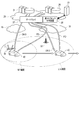
- FIG. 1 is a diagram illustrating an example of a communication system according to the present embodiment.
- FIG. 2 is a diagram illustrating an example of a communication system according to the present embodiment.
- FIG. 3 is a block diagram showing the configuration of the abnormal traffic analyzer according to this embodiment.
- FIG. 4 is a block diagram showing a functional configuration of the abnormal traffic detection engine in the present embodiment.
- FIG. 5 is a flowchart showing the operation of the monitoring target information management server in this embodiment.
- FIG. 6 is a diagram illustrating an example of a management table managed in the monitoring target information management server.
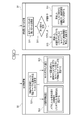
- FIG. 7 is a diagram showing the flow of processing of the abnormal traffic analyzer.
- FIGS. 1 and 2 are diagrams illustrating an example of a communication system according to the present embodiment.
- the communication system shown in FIGS. 1 and 2 is a system that realizes an autonomous mobility system for automatically driving a car or the like, for example.
- the autonomous mobility system transmits, for example, various data (probe data) detected by various sensors and devices provided in an automobile or the like from, for example, an IoT device 40 installed in the automobile to a server.
- the autonomous mobility system reflects probe data received from a number of IoT devices such as automobiles in a dynamic map in real time, and transmits the dynamic map data to the IoT devices of the automobile.
- the automobile executes automatic driving control based on the dynamic map data.
- data (traffic) transmission / reception between an IoT device mounted on an automobile or the like and a server is performed using a plurality of different communication methods. Using any one of the communication paths.
- a plurality of communication methods for example, one of LTE (Long Term Evolution) communication using a mobile network (mobile network 33) and Wi-Fi communication using the Internet 16 is selected and used. It shall be possible.
- the communication is not limited to LTE communication and Wi-Fi communication, and other communication methods can be used. Furthermore, not only two communication methods but also three or more communication methods may be selected and used.
- a core network 10 (10-1,..., 10-m) is provided on the Internet 16.
- a cloud server 12 a dynamic map server 14, and a monitoring target information management server 15 are provided.
- the cloud server 12 is a server that supports various services.
- the cloud server 12 includes an authentication server that identifies an IoT device connected to the Internet 16 via a communication path using the Wi-Fi communication method.
- the monitoring target information management server 15 is a server that manages information related to the IoT device 40 to be monitored, such as a terminal (UE: User Equipment) mounted on an automobile or the like.
- the monitoring target information management server 15 manages, for example, the service used by the terminal, the edge at which the terminal transmits / receives data (local network 20), the correspondence between the cell (base station 32) corresponding to the current location of the terminal, and the like.
- the monitoring target information management server 15 detects a plurality of local networks. 20 (20-1,..., 20-n), a message for notifying that the target IoT device has moved to the abnormal traffic analyzer 28 (28-1,..., 28-n). Will be broadcast.
- the monitoring target information management server 15 receives a message from the authentication server and a mobile network management server (not shown) provided in the mobile network 33 for the IoT device to be monitored, and selects the IoT device. In association with a unique identifier (IoT identifier) to be identified, the status of communication by the Wi-Fi communication scheme and the communication by the LTE communication scheme of the IoT devices to be monitored are integratedly managed.
- IoT identifier a unique identifier
- the dynamic map server 14 creates a dynamic map based on data (probe data) received from a plurality of IoT devices, and distributes the dynamic map data to the terminal (IoT device). For example, the dynamic map server 14 targets a dynamic map higher than the dynamic map managed by the dynamic map server 24 (24-1,..., 24-n) of the local network 20 (20-1,..., 20-n). And
- the local network 20 (20-1,..., 20-n) is a network for realizing a communication system (autonomous mobility system) by an edge computing method. That is, a network slice that provides an autonomous mobility system service is configured at a position closer to the IoT device (terminal) than the core network 10. Thereby, low-latency communication between the IoT device and the server is realized.
- edge servers 22 (22-1..., 22-n) that provide services are distributed and arranged in a plurality of local networks 20-1,.
- FIG. 2 shows the relationship between one local network 20 and, for example, an IoT device 40 mounted on a car.
- a dynamic map server 24 In the local network 20, a dynamic map server 24, a probe collection server 26, a gateway 27, and an abnormal traffic analysis device 28 are arranged in order to provide an autonomous mobility system service.
- the local networks 20-1,..., 20-n are configured in the same manner, and detailed description thereof is omitted.
- the dynamic map server 24 creates a dynamic map based on data (probe data PD) from a plurality of IoT devices 40 collected by the probe collection server 26, and transmits the dynamic map data DMD through the gateway 27 to the IoT device 40. Deliver to.
- the dynamic map server 24 manages a dynamic map in a range that is more local than the dynamic map server 14 provided in the core network 10.
- the probe collection server 26 receives and records data (probe data PD) transmitted from the plurality of IoT devices 40 through the gateway 27.
- the probe collection server 26 provides probe data collected from the IoT device 40 to the dynamic map server 24.
- the probe data includes various data such as the driving position of the automobile, vehicle speed, braking, and fuel consumption.
- the gateway 27 connects the local network 20 (network slice) to another network.
- the gateway 27 receives, for example, data from the IoT device 40 connected to the Wi-Fi access point 30 through the Internet 16.
- the gateway 27 receives data from the IoT device 40 connected to the base station 32 through the mobile network 33.
- the gateway 27 cooperates with the abnormal traffic analysis device 28 and has a function of blocking abnormal traffic transmitted from, for example, a malicious IoT device 42 determined to be abnormal by the analysis by the abnormal traffic analysis device 28.
- the abnormal traffic analysis device 28 operates in cooperation with the gateway 27 and operates as an abnormal traffic detection engine for detecting abnormal traffic.
- the abnormal traffic analysis device 28 inputs and analyzes the traffic (mirroring traffic) transmitted / received through the gateway 27, and executes detection / determination of abnormal traffic transmitted from, for example, a malicious IoT device 42.
- FIG. 3 is a block diagram showing the configuration of the abnormal traffic analyzer 28 in the present embodiment.
- the abnormal traffic analysis device 28 includes a computer that executes a program, and includes a processor 28A, a memory 28B, a communication interface 28C, and a storage device 28D.
- the processor 28A is, for example, a CPU (Central Processing Unit), and controls each unit of the abnormal traffic analysis device 28 by executing a program stored in the memory 28B.
- the processor 28A executes the abnormal traffic analysis program P, thereby realizing an abnormal traffic detection engine (shown in FIG. 4) for detecting abnormal traffic transmitted and received through the gateway 27.
- the abnormal traffic detection engine includes a functional module and a database.
- the memory 28B is used as a work area for processing by the processor 28A, and stores programs and data.
- the communication interface 28C controls communication under the processor 28A.
- the storage device 28D is, for example, an HDD (Hard Disk Drive) or an SSD (Solid State Drive), and stores programs executed by the processor 28A and various data.
- the programs stored in the storage device 28D include an abnormal traffic analysis program P. Further, along with the execution of the abnormal traffic analysis program P, a traffic data database DB1, a UE-specific threat level database DB2, an analysis result log DB3, and the like are stored.
- FIG. 4 is a block diagram showing a functional configuration of the abnormal traffic detection engine 50 in the present embodiment.
- the abnormal traffic detection engine 50 is realized by executing the abnormal traffic analysis program P by the processor 28A.
- the functional module 52 of the abnormal traffic detection engine 50 includes a traffic reception analysis unit M1, an analysis method determination unit M2, an analysis unit M3, an analysis result acquisition unit M4, and a multiple communication management unit M5. Further, as a database 54 for storing data processed by the functional module 52, a traffic data database DB1, a UE-specific threat level database DB2, and an analysis result log DB3 are provided.
- the traffic reception analysis unit M1 receives the same traffic (mirroring traffic) as the traffic transmitted / received to / from the gateway 27.
- the traffic received by the traffic reception analysis unit M1 includes traffic received from one IoT device 40 via a plurality of communication paths using different communication methods (LTE communication, Wi-Fi communication).
- the traffic reception analysis unit M1 records the traffic data, analyzes the traffic (header part and payload part), inquires about the communication path of the packet to the multiple communication management part M5, generates entry data including data indicating the communication path, and the like. Execute.
- the analysis method determination unit M2 determines an analysis algorithm for detecting a traffic abnormality and a parameter used for analysis according to the analysis algorithm according to the communication path specified by the multiple communication management unit M5.
- the analysis unit M3 performs analysis on the traffic data.
- the analysis unit M3 has a plurality of analysis algorithms corresponding to each of a plurality of communication paths (communication methods) through which traffic is transmitted, and analyzes the traffic according to the analysis algorithm and parameters determined by the analysis method determination unit M2. Execute.
- the analysis result acquisition unit M4 acquires and records the analysis result obtained by the analysis unit M3.
- the multi-communication management unit M5 manages the communication path of traffic received by the traffic reception analysis unit M1, and specifies the communication path in response to an inquiry from the traffic reception analysis unit M1.
- FIG. 5 is a flowchart showing the operation of the monitoring target information management server 15 in the present embodiment.
- the UE information management process (step S2) shown in FIG. 5 will be described.
- FIG. 6 is a diagram illustrating an example of a management table managed in the monitoring target information management server 15.
- the IoT device 40 switches the communication path (communication method) according to, for example, the operation status of the own device, the position of the vehicle, etc., and continues to transmit probe data, for example.
- the monitoring target information management server 15 receives the message from the management server of the mobile network 33 when the IoT device 40 uses LTE communication in order to monitor the operation status of the IoT device 40.
- the UE identification information is notified (step S21).
- the monitoring target information management server 15 holds the IoT identifier (UE information) unique to the IoT device 40 and the identifier or attribute information corresponding to the communication line in the management table in response to the notification of the UE identification information.
- the identifier relating to the communication line is, for example, a terminal identifier (UE identifier) associated with IMSI (International Mobile Subscriber Identity).
- the data serving as attribute information indicating the LTE IP address / connection state is updated with the value of the IP address / UE state in the message (step S22).
- Wi-Fi is authenticated by the authentication server, the correspondence between the Wi-Fi identifier and the IP address is specified and notified by a message.
- a communication path (here, LTE communication, Wi-Fi communication) that can be used is specified. Therefore, in the management table, the data indicating the usage status of each of the LTE communication and the Wi-Fi communication is managed in association with the IoT identifier. Since the management table shown in FIG. 6 is held, the IMSI and the Wi-Fi identifier are sequentially updated, so that when the IoT device 40 is switched to one of a plurality of communication paths, the traffic is used. It is possible to specify through which communication method the message is transmitted. Each time the information in the management table shown in FIG. 6 is updated, the traffic is analyzed by sequentially sending it to the multiple communication management unit M5 of the abnormal traffic analyzer 28 (security engine in the present embodiment). It is possible to search which IP address traffic is which communication method.
- the monitoring target information management server 15 receives the message from the cloud authentication server when the IoT device 40 uses Wi-Fi communication in order to monitor the operation status of the IoT device 40.
- the Wi-Fi authentication function Wi-Fi authentication function
- the Wi-Fi identifier and the Wi-Fi IP address are notified (step S21).
- the monitoring target information management server 15 updates the Wi-Fi identifier and the Wi-Fi IP address corresponding to the IoT identifier (UE information) based on the Wi-Fi identifier and the Wi-Fi IP address notified by the message. (Step S23).
- the management table the status of the communication path used by the IoT device specified by the IoT identifier is managed. Therefore, referring to the management table based on the identifier unique to the IoT device included in the traffic received by the abnormal traffic analyzer 28, it is possible to specify the communication path (communication method) through which the traffic is transmitted. it can.
- FIG. 7 is a diagram showing a processing flow of the abnormal traffic analysis device 28 (abnormal traffic detection engine 50).
- the traffic reception analysis unit M1 when receiving traffic, the traffic reception analysis unit M1 generates traffic data D2 and writes it to the traffic database DB1.
- the traffic reception analysis unit M1 parses the traffic, extracts an identifier unique to the IoT device as a transmission source added to the header part, selects a packet to be analyzed, IP (internet) protocol) common information such as 5tuple information (source address, destination address, source port number, destination port number, protocol information) in the packet header, payload information, and the like are acquired.
- IP internet
- 5tuple information source address, destination address, source port number, destination port number, protocol information
- the identifier unique to the IoT device is, for example, an IP address or a terminal identifier (UE identifier) of the IoT device.
- the traffic reception analysis unit M1 inquires the traffic communication path to the multiple communication management unit M5 based on the identifier unique to the IoT device.
- the multiple communication management unit M5 inquires the monitoring target information management server 15 about the communication path in response to the inquiry from the traffic reception analysis unit M1.
- the monitoring target information management server 15 receives an inquiry based on an identifier unique to the IoT device from the plurality of communication management units M5 (step S1), and determines the inquiry type according to the identifier unique to the IoT device ( Step S12).
- the monitoring target information management server 15 refers to the management table and includes the LTE IP address and the Wi-Fi IP address corresponding to the UE identifier. And a communication path is specified (step S13).
- the monitoring target information management server 15 refers to the management table and identifies the UE identifier and the communication path corresponding to the received IP address (step S14). ).
- the monitoring target information management server 15 returns data indicating the identified communication path to the plurality of communication management units M5.
- the multiple communication management unit M5 of the abnormal traffic analysis device 28 notifies the traffic reception analysis unit M1 of the communication path (communication method) notified from the monitoring target information management server 15.
- the traffic reception analysis unit M1 adds data indicating the communication method (communication path) acquired from the multiple communication management unit M5 to the entry data D1.
- the multiple communication management unit M5 makes an inquiry to the monitoring target information management server 15 in response to a request from the traffic reception analysis unit M1. And a communication path (communication method) may be specified with reference to this management table.
- the data in the management table can be acquired from the monitoring target information management server 15 when there is a change in the status of IoT devices in a specific range.
- the traffic reception analysis unit M1 further generates entry data D1 including information obtained by the syntax analysis and data indicating the communication path specified by the plurality of communication management units M5, and an analysis method determination unit Delivered to M2.
- the analysis method determination unit M2 determines an analysis algorithm and parameters used in the analysis in the analysis unit M3, and adds data indicating these analysis methods to the entry data D1. Delivered to analysis unit M3. That is, the optimal analysis algorithm and parameters are determined according to the communication path (communication method) through which the traffic is transmitted, and instructed to the analysis unit M3.
- the analysis unit M3 acquires the traffic data D2 corresponding to the received entry data D1 from the traffic database DB).
- the analysis unit M3 analyzes the entry data D1 using the analysis method (analysis algorithm, parameter) determined by the analysis method determination unit M2, and analyzes the analysis result D3 and the entry data D1 with the analysis result acquisition unit M4. Delivered to.
- the analysis unit M3 performs analysis while repeatedly resetting the level of detail (degree) of attack detection to determine the threat level for each target entry. A specific example of analysis will be described later.
- the analysis result acquisition unit M4 acquires a threat level D4 (to be described later) for each target entry from the received analysis result D3, and applies it to the rule for determining the threat level of the IoT device to be monitored. A different threat level is determined, and the UE-specific threat level database DB2 is updated.
- the analysis result acquisition unit M4 further stores the received analysis result D3 in the analysis result log DB3.
- the analysis result acquisition unit M4 acquires the target entry-specific threat level D4 from the analysis result D3, and delivers the corresponding entry data D1 and the target entry-specific threat level D4 that need the next analysis to the analysis method determination unit M2.
- the analysis method determination unit M1 determines the analysis method according to the analysis order determination rule, and adds the analysis method to the previous analysis order, the threat level for each entry and the corresponding entry data D1. Is delivered to the analysis unit M3.
- the detection result of the primary detection (analysis A) and the secondary detection (analysis) are linked to information (for example, IP address and terminal ID) specifying the transmission source for the past communication.
- the detection result of the attack is stored for each level of detail (hereinafter also referred to as the order) of the attack detection.
- threat levels derived from attack detection results for each degree of detail are stored in association with each other in the threat level database for each UE DB2.
- the threat level may be a binary value of 0 or 1, or a numerical value of 3 or more may be set. For example, 10 numbers 0, 1,..., 9 are set for the threat level, and the larger the number, the stronger the malignancy, and if the number in the threat level column is 9, it is clearly malignant. Also good.
- the threat level database DB2 for each UE at least a source (for example, IP address or terminal ID) of information received in the past and a threat level of information received in the past are associated with each other and stored in advance as entry data.
- the analysis unit M3 collates each entry in the threat level database DB2 for each UE with the identified source, and determines the level of detail of attack detection for the received information. More specifically, the analysis unit M3 confirms whether or not an entry corresponding to the same source exists in the UE-specific threat level database DB2 for the traffic whose source is specified. The analysis unit M3 may determine the level of detail of attack detection for the received information, for example, using the following analysis order determination rules (1) and (2).
- the degree of detail (order) is set to primary.
- the degree of detail (order) is set to the order one level above the threat level indicated by the entry.
- attack detection algorithm and the degree of detail (order) are determined according to the communication path (communication method) through which the traffic is transmitted.
- Examples of attack detection algorithms that can be used in this embodiment include rule-based attack detection, port scanning detection, port change detection, traffic flow change detection, packet reception timing change detection, DPI, and time series data. Examples include attack detection that detects anomalies based on a deviation between data predicted using acquired data and measured data. As the attack detection algorithm is more detailed and expensive, the degree of detail (order) is set higher.
- the analysis unit M3 performs attack detection based on the determined degree of detail (order) (analysis parameter) for the received traffic.
- the analysis unit M3 passes the analysis result D3 to the analysis result acquisition unit M4.
- the analysis result acquisition unit M4 stores information specifying the transmission source and the detection result (target entry-specific threat level D4) in the analysis result log DB3 and UE-specific threat level database DB2.
- the analysis result log DB 3 includes an anomaly identifier, a time stamp, information for identifying a transmission source (IP address and terminal ID), detection results for each detail level, the number of detections for each detail level, a final detection result, a handled flag, and the like. Saved.
- the analysis unit M3 determines the necessity of high-level attack detection for the received traffic.
- the analysis result acquisition unit M4 uses the analysis result by the analysis unit log DB3 and the UE as the analysis result by the analysis unit M3. Saved in the threat level database DB2.
- the attack detection result is not normal, the following cases (1) and (2) can be considered.
- the analysis unit M3 again determines the level of detail of attack detection for the received information based on the result of attack detection.
- the analysis unit M3 again executes attack detection based on the degree of detail (order) determined again.
- the analysis unit M3 determines the necessity of higher-order attack detection. In this way, as long as it is determined that the attack detection result is not normal, it is repeatedly executed.
- the following specific methods (1) to (4) can be considered as a method for redetermining the degree of detail (order) of the analysis unit M3.
- level of detail (degree) of target attack detection is always increased by one.
- the attack detection is aborted at the same time, so that computational resources are not wasted.
- the level of detail corresponding to the registered threat level is set first, so that attack detection with a low level of detail is skipped as appropriate and calculated. Resources are not wasted.
- the abnormal traffic analysis device 28 of the present embodiment it is possible to effectively use the calculation resources.
- a traffic communication path is specified, and an analysis algorithm and an analysis parameter are selected accordingly.
- DOS Delivery of Service attack
- the abnormal traffic analysis device 28 in the present embodiment identifies the communication path (communication method) through which the traffic has been transmitted, and uses the analysis algorithm and analysis parameters corresponding to the communication path (communication method) to handle the traffic. Perform analysis. Therefore, even if the communication path is changed by the application of the IoT device 40, it is possible to perform an appropriate analysis regardless of the communication path, and it is possible to improve the detection rate of abnormal traffic.
- the methods described in the embodiments are, for example, magnetic disks (flexible disks, hard disks, etc.), optical disks (CD-ROM, DVD, MO, etc.) as programs (software means) that can be executed by a computer (computer). ), Stored in a recording medium such as a semiconductor memory (ROM, RAM, flash memory, etc.), or transmitted through a communication medium for distribution.
- the program stored on the medium side includes a setting program that configures software means (including not only the execution program but also a table and data structure) in the computer.
- a computer that implements this apparatus reads a program recorded on a recording medium, constructs software means by a setting program as the case may be, and executes the above-described processing by controlling the operation by this software means.
- the recording medium referred to in this specification is not limited to distribution, but includes a storage medium such as a magnetic disk or a semiconductor memory provided in a computer or a device connected via a network.
- the present invention is not limited to the above-described embodiment, and various modifications can be made without departing from the scope of the invention in the implementation stage.
- the embodiments may be appropriately combined as much as possible, and in that case, the combined effect can be obtained.
- the above embodiments include inventions at various stages, and various inventions can be extracted by appropriately combining a plurality of disclosed constituent elements.
Landscapes
- Engineering & Computer Science (AREA)
- Computer Networks & Wireless Communication (AREA)
- Signal Processing (AREA)
- Computer Security & Cryptography (AREA)
- Computer Hardware Design (AREA)
- Computing Systems (AREA)
- General Engineering & Computer Science (AREA)
- Data Exchanges In Wide-Area Networks (AREA)
- Mobile Radio Communication Systems (AREA)
Abstract
異常トラヒック分析装置は、1つの機器から異なる通信方式を用いた複数の通信経路を介してトラヒックを受信する受信手段と、前記トラヒックが送信された通信経路を特定する複数通信管理手段と、前記複数通信管理により特定された通信経路に応じて、前記トラヒックの異常を検出するための分析アルゴリズムを決定する分析方法決定手段と、前記分析方法決定手段により決定された分析アルゴリズムを用いて、前記トラヒックが異常トラヒックであるかを分析する分析手段と、前記分析手段による分析結果を記録させる分析結果記録手段とを有する。
Description
本発明は、SIEM(Security Information and Event Management)、セキュリティエンジン、ヘテロジーニアスネットワーク等に適用可能な異常トラヒック分析装置、異常トラヒック分析方法及び異常トラヒック分析プログラムに関する。
近年、IoT(Internet of Things)機器の普及により、多数のIoT機器がネットワークに接続され、大量のトラヒックが発生するようになっている。また、IoT機器は、制御などの用途から、IT機器と比べ低遅延が要求される場合がある。このような傾向から、ネットワークや情報処理にかかわるアーキテクチャの変更が必要であり、その選択肢として、複数の通信方法(通信経路)を使い分けることにより、より効率的にネットワークトラヒックを捌くことが提案されている。
一方、ネットワークを介して提供される各種サービスや、インフラなどに対して攻撃する不正な通信(サイバー攻撃)は、多種多様な手法を用いたものへと変化し、ますます脅威が増大している。従来では、このような不正な通信に対する対策として、不正な通信(異常トラヒック)を検出する装置がネットワークに設けられている。
従来では、1つの対象とするIoT機器からのトラヒックは、例えばLTE(Long Term Evolution)など特定の1つの通信方式を用いて送信することを想定している。このため、不正な通信(異常トラヒック)を検出する装置は、トラヒックの送信に用いられる特定の通信方式に最適化された分析アルゴリズムを用いてトラヒックを分析している。
従って、ネットワークに大量のトラヒックが発生することに対して、1つのIoT機器からトラヒックを送信する際に、アプリケーション側で通信方式を選択し、発生するトラヒック内容が変更されてしまうと、トラヒックに対して適切な分析ができない状況が発生する可能性がある。
本発明は上記課題を解決するためになされたものであり、本発明の目的は、機器からトラヒックが送信される通信経路に関係なく適切な分析をすることが可能な異常トラヒック分析装置、異常トラヒック分析方法及び異常トラヒック分析プログラムを提供することにある。
本発明は、課題を解決するために、以下のような手段を講じている。
本発明の第1の態様は、異常トラヒック分析装置は、1つの機器から異なる通信方式を用いた複数の通信経路を介してトラヒックを受信する受信手段と、前記トラヒックが送信された通信経路を特定する複数通信管理手段と、前記複数通信管理により特定された通信経路に応じて、前記トラヒックの異常を検出するための分析アルゴリズムを決定する分析方法決定手段と、前記分析方法決定手段により決定された分析アルゴリズムを用いて、前記トラヒックが異常トラヒックであるかを分析する分析手段と、前記分析手段による分析結果を記録させる分析結果記録手段とを有する。
本発明によれば、特定された通信経路に応じた適切な分析アルゴリズムを用いてトラヒックに対して分析を実施するので、異常トラヒックの検知率の向上が可能となる。
以下、本実施形態について、図面を参照しながら説明する。
図1及び図2は、本実施形態の通信システムの一例を示す図である。図1及び図2に示す通信システムは、例えば自動車等を自動走行させるための自律型モビリティシステムを実現するシステムである。自律型モビリティシステムは、例えば自動車等に設けられた各種のセンサや機器等により検出された各種のデータ(プローブデータ)を、例えば、自動車に搭載されたIoT機器40からサーバに送信する。自律型モビリティシステムは、多数の自動車等のIoT機器から受信されたプローブデータをリアルタイムでダイナミックマップに反映させ、このダイナミックマップのデータを自動車のIoT機器に送信する。自動車は、ダイナミックマップのデータをもとに自動走行の制御を実行する。
図1及び図2は、本実施形態の通信システムの一例を示す図である。図1及び図2に示す通信システムは、例えば自動車等を自動走行させるための自律型モビリティシステムを実現するシステムである。自律型モビリティシステムは、例えば自動車等に設けられた各種のセンサや機器等により検出された各種のデータ(プローブデータ)を、例えば、自動車に搭載されたIoT機器40からサーバに送信する。自律型モビリティシステムは、多数の自動車等のIoT機器から受信されたプローブデータをリアルタイムでダイナミックマップに反映させ、このダイナミックマップのデータを自動車のIoT機器に送信する。自動車は、ダイナミックマップのデータをもとに自動走行の制御を実行する。
本実施形態における通信システムでは、ネットワークに大量に発生するトラヒックを効率的に送受信するため、自動車等に搭載されたIoT機器とサーバとのデータ(トラヒック)の送受信を、異なる通信方式を用いた複数の通信経路の何れかを用いて行う。本実施形態では、複数の通信方法として、例えばモバイルネットワーク(移動網33)を使用するLTE(Long Term Evolution)通信と、インターネット16を用いたWi-Fi通信の何れかを選択して用いることができるものとする。
なお、LTE通信とWi-Fi通信に限るものではなく、他の通信方法を用いることもできる。さらに、2つの通信方法に限らず、3つ以上の通信方法を選択して用いることができるようにしても良い。
図1に示す通信システムでは、インターネット16上にコアネットワーク10(10-1,…,10-m)が設けられる。コアネットワーク10には、例えばクラウドサーバ12、ダイナミックマップサーバ14、監視対象情報管理サーバ15が設けられる。クラウドサーバ12は、各種サービスに対応するサーバである。クラウドサーバ12には、Wi-Fi通信方式による通信経路を介してインターネット16に接続されたIoT機器を識別する認証サーバを含む。
監視対象情報管理サーバ15は、自動車等に搭載された端末(UE:User Equipment)など、監視対象とするIoT機器40に関する情報を管理するサーバである。監視対象情報管理サーバ15は、例えば端末が利用するサービス、端末がデータを送受信するエッジ(ローカルネットワーク20)、端末の現在位置に対応するセル(基地局32)の対応関係等を管理する。監視対象情報管理サーバ15は、自動車の走行に伴って端末(IoT機器)が、異なるローカルネットワーク20に対応するセル(基地局32)の範囲に移動したことが検出された場合、複数のローカルネットワーク20(20-1,…,20-n)のそれぞれに含まれる異常トラヒック分析装置28(28-1,…,28-n)に対して、対象とするIoT機器が移動したことを通知するメッセージを同報配信する。
また、監視対象情報管理サーバ15は、監視対象とするIoT機器について、認証サーバ及び移動網33内に設けられた移動網の管理サーバ(図示せず)からのメッセージを受信して、IoT機器を特定する一意の識別子(IoT識別子)と対応づけて、監視対象とするIoT機器のWi-Fi通信方式による通信とLTE通信方式による通信の状況を統合的に管理する。
ダイナミックマップサーバ14は、複数のIoT機器から受信されるデータ(プローブデータ)をもとにダイナミックマップを作成して、ダイナミックマップデータを端末(IoT機器)に配信する。ダイナミックマップサーバ14は、例えば、ローカルネットワーク20(20-1,…,20-n)のダイナミックマップサーバ24(24-1,…,24-n)が管理するダイナミックマップより上位のダイナミックマップを対象とする。
ローカルネットワーク20(20-1,…,20-n)は、通信システム(自律型モビリティシステム)をエッジコンピューティング方式により実現するためのネットワークである。すなわち、コアネットワーク10よりもIoT機器(端末)に近い位置に、自律型モビリティシステムのサービスを提供するネットワークスライスを構成している。これにより、IoT機器とサーバとの間の低遅延通信を実現している。エッジコンピューティング方式による通信システムでは、サービスを提供するエッジサーバ22(22-1.…,22-n)が、複数のローカルネットワーク20-1,…,20-nに分散して配置される。
図2には、1つのローカルネットワーク20と、例えば自動車に搭載されたIoT機器40との関係を示している。
ローカルネットワーク20には、自律型モビリティシステムのサービスを提供するために、ダイナミックマップサーバ24、プローブ収集サーバ26、ゲートウェイ27、異常トラヒック分析装置28が配置される。なお、ローカルネットワーク20-1,…,20-nは、それぞれ同様に構成されるものとして、個々について詳細な説明を省略する。
ダイナミックマップサーバ24は、プローブ収集サーバ26により収集される複数のIoT機器40からのデータ(プローブデータPD)をもとにダイナミックマップを作成して、ゲートウェイ27を通じて、ダイナミックマップデータDMDをIoT機器40に配信する。ダイナミックマップサーバ24は、コアネットワーク10に設けられたダイナミックマップサーバ14よりもローカルな範囲のダイナミックマップを管理する。
プローブ収集サーバ26は、複数のIoT機器40から送信されるデータ(プローブデータPD)を、ゲートウェイ27を通じて受信して記録する。プローブ収集サーバ26は、IoT機器40から収集したプローブデータをダイナミックマップサーバ24に提供する。プローブデータには、自動車の走行位置、車速、ブレーキング、燃費など、様々なデータを含む。
ゲートウェイ27は、ローカルネットワーク20(ネットワークスライス)と他のネットワークとを接続する。ゲートウェイ27は、例えば、Wi-Fiアクセスポイント30と接続されたIoT機器40からのデータを、インターネット16を通じて受信する。また、ゲートウェイ27は、基地局32と接続されたIoT機器40からのデータを、移動網33を通じて受信する。ゲートウェイ27は、異常トラヒック分析装置28と連携し、異常トラヒック分析装置28による分析によって異常と判断された、例えば悪意のあるIoT機器42から送信される異常トラヒックを遮断する機能を有する。
異常トラヒック分析装置28は、ゲートウェイ27と連携して動作し、異常トラヒックを検出するための異常トラヒック検知エンジンとして動作する。異常トラヒック分析装置28は、ゲートウェイ27を通じて送受信されるトラヒック(ミラーリングトラヒック)を入力して分析し、例えば悪意のあるIoT機器42から送信される異常トラヒックの検知・判断を実行する。
図3は、本実施形態における異常トラヒック分析装置28の構成を示すブロック図である。
異常トラヒック分析装置28は、プログラムを実行するコンピュータを備えており、プロセッサ28A、メモリ28B、通信インタフェース28C、記憶装置28Dを有する。
異常トラヒック分析装置28は、プログラムを実行するコンピュータを備えており、プロセッサ28A、メモリ28B、通信インタフェース28C、記憶装置28Dを有する。
プロセッサ28Aは、例えばCPU(Central Processing Unit)であり、メモリ28Bに記憶されたプログラムを実行することで、異常トラヒック分析装置28の各部を制御する。プロセッサ28Aは、異常トラヒック分析プログラムPを実行することで、ゲートウェイ27を通じて送受信される異常トラヒックを検出するための異常トラヒック検知エンジン(図4に示す)を実現する。異常トラヒック検知エンジンには、機能モジュール及びデータベースを含む。
メモリ28Bは、プロセッサ28Aによる処理の作業エリアとして使用され、プログラムやデータが記憶される。
通信インタフェース28Cは、プロセッサ28Aのもとで通信を制御する。
記憶装置28Dは、例えばHDD(Hard Disk Drive)またはSSD(Solid State Drive)であり、プロセッサ28Aにより実行されるプログラム、各種データが記憶される。記憶装置28Dに記憶されるプログラムには、異常トラヒック分析プログラムPを含む。また、異常トラヒック分析プログラムPの実行に伴い、トラヒックデータデータベースDB1、UE別脅威レベルデータベースDB2、分析結果ログDB3等が記憶される。
図4は、本実施形態における異常トラヒック検知エンジン50の機能構成を示すブロック図である。異常トラヒック検知エンジン50は、プロセッサ28Aにより異常トラヒック分析プログラムPを実行することにより実現される。
異常トラヒック検知エンジン50の機能モジュール52には、トラヒック受信解析部M1、分析方法決定部M2、分析部M3、分析結果取得部M4、複数通信管理部M5が含まれる。また、機能モジュール52により処理されるデータを記憶するデータベース54として、トラヒックデータデータベースDB1、UE別脅威レベルデータベースDB2、分析結果ログDB3が設けられる。
トラヒック受信解析部M1は、ゲートウェイ27に送受信されるトラヒックと同じトラヒック(ミラーリングトラヒック)を受信する。トラヒック受信解析部M1により受信されるトラヒックは、1つのIoT機器40から異なる通信方式(LTE通信、Wi-Fi通信)を用いた複数の通信経路を介して受信されたトラヒックを含む。トラヒック受信解析部M1は、トラヒックデータの記録、トラヒック(ヘッダ部及びペイロード部)についての解析、複数通信管理部M5に対するパケットの通信経路の問い合わせ、通信経路を示すデータを含むエントリデータの生成等を実行する。
分析方法決定部M2は、複数通信管理部M5により特定された通信経路に応じて、トラヒックの異常を検出するための分析アルゴリズム、及び分析アルゴリズムに従う分析に使用されるパラメータを決定する。
分析部M3は、トラヒックデータに対する分析を実行する。分析部M3は、トラヒックが送信される複数の通信経路(通信方法)のそれぞれに対応する複数の分析アルゴリズムを有し、分析方法決定部M2によって決定された分析アルゴリズム及びパラメータに応じてトラヒックに対する分析を実行する。
分析結果取得部M4は、分析部M3による分析結果を取得して記録させる。
複数通信管理部M5は、トラヒック受信解析部M1により受信されるトラヒックの通信経路を管理し、トラヒック受信解析部M1からの問い合わせに応じて通信経路を特定する。
次に、本実施形態の通信システムにおける異常トラヒックの検出のための動作について説明する。
まず、監視対象情報管理サーバ15によるIoT機器40のWi-Fi通信方式による通信とLTE通信方式による通信の状況を統合的に管理する処理について説明する。
まず、監視対象情報管理サーバ15によるIoT機器40のWi-Fi通信方式による通信とLTE通信方式による通信の状況を統合的に管理する処理について説明する。
図5は、本実施形態における監視対象情報管理サーバ15の動作を示すフローチャートである。ここでは、図5に示すUE情報管理処理(ステップS2)について説明する。図6は、監視対象情報管理サーバ15において管理される管理テーブルの一例を示す図である。
IoT機器40は、例えば自機器の動作状況や自動車の位置などに応じて通信経路(通信方法)を切り替えて、例えばプローブデータの送信を継続する。
監視対象情報管理サーバ15は、IoT機器40の動作状況を監視するため、IoT機器40がLTE通信を利用する場合には、移動網33の管理サーバからのメッセージを受信する。管理サーバからのメッセージでは、UE識別情報が通知される(ステップS21)。
監視対象情報管理サーバ15は、UE識別情報の通知に応じて、管理テーブルにIoT機器40に固有のIoT識別子(UE情報)と通信回線に対応する識別子や属性情報を対応させて保持する。通信回線に関する識別子は、例えばIMSI(International Mobile Subscriber Identity)と対応づけた端末識別子(UE識別子)とする。また、メッセージ中のIPアドレス/UE状態の値で、LTE IPアドレス/接続状態を示す属性情報となるデータを更新する(ステップS22)。Wi-Fiについては、認証サーバによって認証され、Wi-Fi識別子とIPアドレスの対応が特定されてメッセージにより通知される。IoT識別子に対応するIMSI及びWi-Fi識別子が示すIoT機器では、予め使用できる通信経路(ここでは、LTE通信、Wi-Fi通信)が特定されている。従って、管理テーブルでは、LTE通信とWi-Fi通信のそれぞれの使用状況を示すデータを、IoT識別子により紐付けて管理する。前述の図6に示す管理テーブルを保持しているため、IMSIやWi-Fi識別子が逐次、更新されることにより、IoT機器40が複数の通信経路の何れかに切り替えて用いた際に、トラヒックがどの通信方式による通信経路を通じて送信されたか特定することが可能になる。図6に示す管理テーブルの情報が更新されるたびに逐次的に異常トラヒック分析装置28(本実施形態におけるセキュリティエンジン)の複数通信管理部M5に対して送付することにより、トラヒックを分析する際にどのIPアドレスのトラヒックがどの通信方式かを検索することができる。
監視対象情報管理サーバ15は、IoT機器40の動作状況を監視するため、IoT機器40がWi-Fi通信を利用する場合には、クラウドの認証サーバからのメッセージを受信する。認証サーバ(Wi-Fi認証機能)からのメッセージでは、Wi-Fi識別子とWi-Fi IPアドレスが通知される(ステップS21)。
監視対象情報管理サーバ15は、メッセージにより通知されたWi-Fi識別子とWi-Fi IPアドレスをもとに、IoT識別子(UE情報)に対応するWi-Fi識別子やWi-Fi IPアドレスを更新する(ステップS23)。
こうして、管理テーブルでは、IoT識別子により特定されるIoT機器が使用する通信経路の状況が管理される。従って、異常トラヒック分析装置28において受信されるトラヒックに含まれるIoT機器に固有の識別子をもとに、管理テーブルを参照することにより、トラヒックが送信された通信経路(通信方法)を特定することができる。
次に、本実施形態における異常トラヒック分析装置28の動作について、図4及び図7を参照しながら説明する。図7は、異常トラヒック分析装置28(異常トラヒック検知エンジン50)の処理の流れを示す図である。
(1)まず、トラヒック受信解析部M1は、トラヒックを受信すると、トラヒックデータD2を生成してトラヒックデータベースDB1へ書き出す。
(2)トラヒック受信解析部M1は、トラヒックに対して構文解析して、ヘッダ部に付加された送信元とするIoT機器に固有の識別子の抽出の他、分析対象のパケットの選別、IP(internet protocol)パケットヘッダにある5tupple情報(送信元アドレス、宛先アドレス、送信元ポート番号、宛先ポート番号、プロトコル情報)等の共通情報と、ペイロード情報等を取得する。IoT機器に固有の識別子は、例えばIPアドレスあるいはIoT機器の端末識別子(UE識別子)である。
トラヒック受信解析部M1は、IoT機器に固有の識別子をもとに、複数通信管理部M5にトラヒックの通信経路を問い合わせる。複数通信管理部M5は、トラヒック受信解析部M1からの問い合わせに応じて、監視対象情報管理サーバ15に通信経路を問い合わせる。
監視対象情報管理サーバ15は、複数通信管理部M5からのIoT機器に固有の識別子をもとにした問い合わせを受信し(ステップS1)、IoT機器に固有の識別子に応じた問い合わせ種別を判別する(ステップS12)。
複数通信管理部M5から受信した識別子が端末識別子(UE識別子)の場合、監視対象情報管理サーバ15は、管理テーブルを参照して、UE識別子に対応するLTE IPアドレスとWi-Fi IPアドレスをもとに通信経路を特定する(ステップS13)。
一方、複数通信管理部M5から受信した識別子がIPアドレスの場合、監視対象情報管理サーバ15は、管理テーブルを参照して、受信したIPアドレスに対応するUE識別子と通信経路を特定する(ステップS14)。
監視対象情報管理サーバ15は、特定した通信経路を示すデータを複数通信管理部M5に返却する。
異常トラヒック分析装置28の複数通信管理部M5は、監視対象情報管理サーバ15から通知された通信経路(通信方法)をトラヒック受信解析部M1に通知する。トラヒック受信解析部M1は、複数通信管理部M5から取得された通信方式(通信経路)を示すデータをエントリデータD1に加える。
なお、前述した説明では、複数通信管理部M5は、トラヒック受信解析部M1からの要求に応じて、監視対象情報管理サーバ15に対して問い合わせするとしているが、監視対象情報管理サーバ15から管理テーブルを取得しておき、この管理テーブルを参照して通信経路(通信方法)を特定するようにしても良い。管理テーブルのデータは、特定の範囲にあるIoT機器について、状況の変化があった場合に監視対象情報管理サーバ15から取得することができる。
(3)トラヒック受信解析部M1は、さらに、構文解析により得られた各情報、複数通信管理部M5により特定された通信経路を示すデータとを含むエントリデータD1を生成して、分析方法決定部M2へ引渡す。
(4)分析方法決定部M2は、受け取ったエントリデータD1をもとに、分析部M3における分析で用いる分析アルゴリズム及びパラメータを決定し、これらの分析方法を示すデータをエントリデータD1に付加して分析部M3へ引渡す。すなわち、トラヒックが送信された通信経路(通信方法)に応じた、最適な分析アルゴリズムとパラメータが決定され、分析部M3に指示される。
(5)分析部M3は、受け取ったエントリデータD1に対応するトラヒックデータD2を、トラヒックデータベースDB)から取得する。
(6)分析部M3は、分析方法決定部M2において決定された分析方法(分析アルゴリズム、パラメータ)を用いて、エントリデータD1について分析し、その分析結果D3及びエントリデータD1を分析結果取得部M4へ引渡す。分析部M3は、例えば攻撃検知の詳細度(次数)の再設定を繰り返しながら分析して、対象エントリ別の脅威レベルを判定する分析を実行する。分析の具体例については後述する。
(7)分析結果取得部M4は、受け取った分析結果D3から対象エントリ別脅威レベルD4(後述する)を取得して、監視対象のIoT機器の脅威レベルを決定するためのルールに適用してUE別脅威レベルを決定し、UE別脅威レベルデータベースDB2を更新する。
(8)分析結果取得部M4は、更に、受け取った分析結果D3を分析結果ログDB3へ保存する。
(9)分析結果取得部M4は、分析結果D3から対象エントリ別脅威レベルD4を取得し、次の分析が必要な該当エントリデータD1および対象エントリ別脅威レベルD4を分析方法決定部M2へ引渡す。
なお、(3)分析方法決定部M1は、1つ前の分析次数および対象エントリ別脅威レベルと該当エントリデータD1を、分析次数決定ルールにより分析方法を決定して分析方法が付加されたエントリデータを分析部M3へ引渡す。
ここで、分析部M3による分析の具体例について説明する。
UE別脅威レベルデータベースDB2には、過去の通信を対象として、発信元を特定する情報(例えばIPアドレスや端末ID)に紐づけて、一次検知(分析A)の検知結果、二次検知(分析B)の検知結果、…といった具合に、攻撃検知の詳細度(以下、次数ともいう)ごとに、攻撃検知の結果が記憶されている。これに加え、UE別脅威レベルデータベースDB2には、詳細度ごとの攻撃検知結果から導き出される脅威レベルが対応付けられて記憶されている。
UE別脅威レベルデータベースDB2には、過去の通信を対象として、発信元を特定する情報(例えばIPアドレスや端末ID)に紐づけて、一次検知(分析A)の検知結果、二次検知(分析B)の検知結果、…といった具合に、攻撃検知の詳細度(以下、次数ともいう)ごとに、攻撃検知の結果が記憶されている。これに加え、UE別脅威レベルデータベースDB2には、詳細度ごとの攻撃検知結果から導き出される脅威レベルが対応付けられて記憶されている。
脅威レベルは、0または1の2値としてもよいし、3値以上の数値を設定してもよい。例えば脅威レベルに10種類の数字0,1,…,9を設定し、数字が大きければ大きいほど悪性度が強いことを意味するものとし、脅威レベルカラムの数字が9であれば明らかな悪性としてもよい。
UE別脅威レベルデータベースDB2には、少なくとも、過去に受信した情報の発信元(例えばIPアドレスや端末ID)と過去に受信した情報の脅威レベルとが対応付けられてエントリデータとして予め記憶されているものとする。
分析部M3は、UE別脅威レベルデータベースDB2の各エントリと特定された発信元とを照合し、受信した情報に対する攻撃検知の詳細度を決定する。より具体的には、分析部M3は、発信元が特定されたトラヒックに対し、これと同一の発信元に該当するエントリがUE別脅威レベルデータベースDB2に存在するか否かを確認する。分析部M3は、例えば以下のような分析次数決定ルール(1)(2)で、受信した情報に対する攻撃検知の詳細度を決定してもよい。
(1)具体例
UE別脅威レベルデータベースDB2に対応するエントリがなかった場合、詳細度(次数)を1次と設定する。一方、UE別脅威レベルデータベースDB2に対応するエントリがあった場合、詳細度(次数)をエントリが示す脅威レベルの一つ上の次数に設定する。
UE別脅威レベルデータベースDB2に対応するエントリがなかった場合、詳細度(次数)を1次と設定する。一方、UE別脅威レベルデータベースDB2に対応するエントリがあった場合、詳細度(次数)をエントリが示す脅威レベルの一つ上の次数に設定する。
(2)具体例
UE別脅威レベルデータベースDB2に対応するエントリがなかった場合、詳細度(次数)を1次と設定する。一方、UE別脅威レベルデータベースDB2に対応するエントリがあった場合、詳細度(次数)をエントリが示す脅威レベルと等しい次数に設定する。
UE別脅威レベルデータベースDB2に対応するエントリがなかった場合、詳細度(次数)を1次と設定する。一方、UE別脅威レベルデータベースDB2に対応するエントリがあった場合、詳細度(次数)をエントリが示す脅威レベルと等しい次数に設定する。
本実施形態の異常トラヒック分析装置28では、トラヒックが送信された通信経路(通信方法)に応じて、攻撃検知アルゴリズムと詳細度(次数)が決定されるものとする。本実施例で用いることができる攻撃検知アルゴリズムとしては、例えばルールベース攻撃検知、ポートスキャニングの検知、利用ポートの変化検知、トラヒック流量の変化検知、パケット受信タイミングの変化検知、DPI、時系列データとして取得されたデータを用いて予測されたデータと、実測されたデータとのはずれ具合で異常を検知する攻撃検知などが挙げられる。攻撃検知アルゴリズムが詳細かつ高コストであるほど、詳細度(次数)が高く設定される。
次に、分析部M3は、受信したトラヒックに対して、決定された詳細度(次数)(分析パラメータ)に基づく攻撃検知を実行する。
攻撃検知の結果が正常であった場合、分析部M3は、分析結果D3を分析結果取得部M4に渡す。分析結果取得部M4は、発信元を特定する情報と検知結果(対象エントリ別脅威レベルD4)を分析結果ログDB3およびUE別脅威レベルデータベースDB2に保存する。分析結果ログDB3には、アノマリ識別子、タイムスタンプ、発信元を特定する情報(IPアドレスや端末ID)、詳細度ごとの検知結果、詳細度ごとの検知回数、最終検知結果、対処済フラグなどが保存される。
一方、攻撃検知の結果が正常でない場合(懸念有、または異常有であった場合)、分析部M3は、受信したトラヒックに対する高次な攻撃検知の必要性を判断する。高次な攻撃検知の必要性があると判断されなかった場合、分析結果取得部M4は、分析部M3による分析結果として、発信元を特定する情報と、検知結果を分析結果ログDB3およびUE別脅威レベルデータベースDB2に保存する。
攻撃検知の結果が正常でない場合として、具体的には以下のようなケース(1)(2)が考えられる。(1)該当の通信が異常(不正)であることが明白であるため、さらに高次な攻撃検知を実行する必要性が乏しい。例えば、前述の脅威レベルカラムの数字が9である場合などには、該当の通信が悪性であることが明白であるため、さらに高次な攻撃検知を省略することができ、計算リソースを効果的に用いることができる。(2)すでに最高次の攻撃検知が実行されており、これよりも高次な攻撃検知が実行できない。
一方、高次な攻撃検知の必要性があると判断された場合、分析部M3は、攻撃検知の結果に基づいて、受信した情報に対する攻撃検知の詳細度を再度決定する。分析部M3は、再度決定された詳細度(次数)に基づく攻撃検知を再度実行する。攻撃検知の結果が正常でないと判断される場合、分析部M3は、さらに高次な攻撃検知の必要性を判断する。このように、攻撃検知の結果が正常でないと判断される限りにおいて、繰り返し実行される。分析部M3の詳細度(次数)の再決定方法として以下の具体的方法(1)~(4)が考えられる。
(1)具体例
対象の攻撃検知の詳細度(次数)を常に1増やす。
対象の攻撃検知の詳細度(次数)を常に1増やす。
(2)具体例
攻撃検知アルゴリズムの出力が、正常/懸念有り/異常有りの3段階で表現される場合、
出力=懸念有り→判断結果=Yes(次数を1増やす)
出力=異常有り→判断結果=Yes(次数を2増やす)
(3)具体例
攻撃検知アルゴリズムの出力が、正常/懸念有り/異常有りの3段階で表現される場合、
出力=懸念有り→判断結果=No(次数を増やさない→S15aN→エンド)
出力=異常有り→判断結果=Yes(次数を1増やす)
(4)具体例
攻撃検知アルゴリズムの出力が、異常の有無を数値で表現する場合。例えば、攻撃検知アルゴリズムの出力が0.0~1.0であって、値が1.0に近づくほど異常性が高く、異常有無判断の閾値が0.5だった場合。
攻撃検知アルゴリズムの出力が、正常/懸念有り/異常有りの3段階で表現される場合、
出力=懸念有り→判断結果=Yes(次数を1増やす)
出力=異常有り→判断結果=Yes(次数を2増やす)
(3)具体例
攻撃検知アルゴリズムの出力が、正常/懸念有り/異常有りの3段階で表現される場合、
出力=懸念有り→判断結果=No(次数を増やさない→S15aN→エンド)
出力=異常有り→判断結果=Yes(次数を1増やす)
(4)具体例
攻撃検知アルゴリズムの出力が、異常の有無を数値で表現する場合。例えば、攻撃検知アルゴリズムの出力が0.0~1.0であって、値が1.0に近づくほど異常性が高く、異常有無判断の閾値が0.5だった場合。
出力=0.5以上0.6未満→判断結果=Yes(次数を1増やす)
出力=0.6以上0.7未満→判断結果=Yes(次数を2増やす)
出力=0.7以上0.8未満→判断結果=Yes(次数を3増やす)
出力=0.8以上0.9未満→判断結果=Yes(次数を4増やす)
出力=0.9以上→判断結果=Yes(次数を5増やす)
本実施例の異常トラヒック分析装置28によれば、危険性の低いIoT機器(機器)については、早々に攻撃検知を打ち切るため、計算リソースが無駄にならない。
出力=0.6以上0.7未満→判断結果=Yes(次数を2増やす)
出力=0.7以上0.8未満→判断結果=Yes(次数を3増やす)
出力=0.8以上0.9未満→判断結果=Yes(次数を4増やす)
出力=0.9以上→判断結果=Yes(次数を5増やす)
本実施例の異常トラヒック分析装置28によれば、危険性の低いIoT機器(機器)については、早々に攻撃検知を打ち切るため、計算リソースが無駄にならない。
また、明らかに不正なIoT機器についても同様に、早々に攻撃検知を打ち切るため、計算リソースが無駄にならない。
また、該当のIoT機器の危険性がグレーゾーンにある場合は、処理を繰り返し実行することにより、攻撃検知の信頼性が担保される。
また、UE別脅威レベルデータベースDB2にエントリとして登録されているIoT機器については、登録済みの脅威レベルに応じた詳細度が最初に設定されるため、詳細度の低い攻撃検知が適宜スキップされ、計算リソースが無駄にならない。
このように、本実施例の異常トラヒック分析装置28によれば、計算リソースを効果的に用いることができる。
なお、前述したトラヒックに対する分析は一例であって、他の分析を対象とすることができる。その場合、前述と同様にして、トラヒックの通信経路を特定し、それにあわせて、分析アルゴリズムおよび分析パラメータを選択する。例えば、DOS(Denial of Service attack)攻撃検知のための分析をする場合において、閾値を通信方式に応じて変更する。
このようにして、本実施形態における異常トラヒック分析装置28では、トラヒックが送信された通信経路(通信方法)を特定し、通信経路(通信方法)に応じた分析アルゴリズム及び分析パラメータを用いてトラヒックに対する分析を実行する。従って、IoT機器40のアプリケーションにより通信経路が変更されたとしても、通信経路に関係なく適切な分析をすることが可能となり、異常トラヒックの検知率の向上が可能となる。
また、各実施形態に記載した手法は、計算機(コンピュータ)に実行させることができるプログラム(ソフトウエア手段)として、例えば磁気ディスク(フレキシブルディスク、ハードディスク等)、光ディスク(CD-ROM、DVD、MO等)、半導体メモリ(ROM、RAM、フラッシュメモリ等)等の記録媒体に格納し、また通信媒体により伝送して頒布することもできる。なお、媒体側に格納されるプログラムには、計算機に実行させるソフトウエア手段(実行プログラムのみならずテーブルやデータ構造も含む)を計算機内に構成させる設定プログラムをも含む。本装置を実現する計算機は、記録媒体に記録されたプログラムを読み込み、また場合により設定プログラムによりソフトウエア手段を構築し、このソフトウエア手段によって動作が制御されることにより上述した処理を実行する。なお、本明細書でいう記録媒体は、頒布用に限らず、計算機内部あるいはネットワークを介して接続される機器に設けられた磁気ディスクや半導体メモリ等の記憶媒体を含むものである。
なお、本願発明は、上記実施形態に限定されるものではなく、実施段階ではその要旨を逸脱しない範囲で種々に変形することが可能である。また、各実施形態は可能な限り適宜組み合わせて実施してもよく、その場合組み合わせた効果が得られる。更に、上記実施形態には種々の段階の発明が含まれており、開示される複数の構成要件における適当な組み合わせにより種々の発明が抽出され得る。
10(10-1,…,10-m)…コアネットワーク
12…クラウドサーバ
14…ダイナミックマップサーバ
16…インターネット
20(20-1,…,20-n)…ローカルネットワーク
22(22-1.…,22-n)…エッジサーバ
24(24-1,…,24-n)…ダイナミックマップサーバ
26(26-1,…,26-n)…プローブ収集サーバ
27(27-1,…,27-n)…ゲートウェイ
28(28-1,…,28-n)…異常トラヒック分析装置
28A…プロセッサ
28B…メモリ
28C…通信インタフェース
28D…記憶装置
30…Wi-Fiアクセスポイント
32…基地局
M1…トラヒック受信解析部
M2…分析方法決定部
M3…分析部
M4…分析結果取得部
M5…複数通信管理部
DB1…トラヒックデータデータベース
DB2…UE別脅威レベルデータベース
DB3…分析結果ログ
12…クラウドサーバ
14…ダイナミックマップサーバ
16…インターネット
20(20-1,…,20-n)…ローカルネットワーク
22(22-1.…,22-n)…エッジサーバ
24(24-1,…,24-n)…ダイナミックマップサーバ
26(26-1,…,26-n)…プローブ収集サーバ
27(27-1,…,27-n)…ゲートウェイ
28(28-1,…,28-n)…異常トラヒック分析装置
28A…プロセッサ
28B…メモリ
28C…通信インタフェース
28D…記憶装置
30…Wi-Fiアクセスポイント
32…基地局
M1…トラヒック受信解析部
M2…分析方法決定部
M3…分析部
M4…分析結果取得部
M5…複数通信管理部
DB1…トラヒックデータデータベース
DB2…UE別脅威レベルデータベース
DB3…分析結果ログ
Claims (5)
- 1つの機器から異なる通信方式を用いた複数の通信経路を介してトラヒックを受信する受信手段と、
前記トラヒックが送信された通信経路を特定する複数通信管理手段と、
前記複数通信管理手段により特定された通信経路に応じて、前記トラヒックの異常を検出するための分析アルゴリズムを決定する分析方法決定手段と、
前記分析方法決定手段により決定された分析アルゴリズムを用いて、前記トラヒックが異常トラヒックであるかを分析する分析手段と、
前記分析手段による分析結果を記録させる分析結果記録手段と
を有する異常トラヒック分析装置。 - 前記複数通信管理手段は、前記トラヒックに含まれる識別子をもとに、前記機器による通信の状況を管理する外部サーバに問い合わせて、前記トラヒックが送信された通信経路を示すデータを取得する請求項1記載の異常トラヒック分析装置。
- 前記分析方法決定手段は、前記複数通信管理手段により特定された通信経路に応じた分析アルゴリズムで使用する分析パラメータを、前記通信経路に応じて変更する請求項1記載の異常トラヒック分析装置。
- 1つの機器から異なる通信方式を用いた複数の通信経路を介してトラヒックを受信する受信工程と、
前記トラヒックが送信された通信経路を特定する複数通信管理工程と、
前記複数通信管理工程により特定された通信経路に応じて、前記トラヒックの異常を検出するための分析アルゴリズムを決定する分析方法決定工程と、
前記分析方法決定工程により決定された分析アルゴリズムを用いて、前記トラヒックが異常トラヒックであるかを分析する分析工程と、
前記分析工程による分析結果を記録させる分析結果記録工程とを有する異常トラヒック分析方法。 - 請求項1乃至3の何れかに記載の異常トラヒック分析装置が具備する各手段が行う処理を、当該異常トラヒック分析装置が備えるコンピュータに実行させる異常トラヒック分析プログラム。
Priority Applications (1)
| Application Number | Priority Date | Filing Date | Title |
|---|---|---|---|
| US16/982,223 US11870792B2 (en) | 2018-03-23 | 2019-03-08 | Abnormal traffic analysis apparatus, abnormal traffic analysis method, and abnormal traffic analysis program |
Applications Claiming Priority (2)
| Application Number | Priority Date | Filing Date | Title |
|---|---|---|---|
| JP2018-057081 | 2018-03-23 | ||
| JP2018057081A JP6973227B2 (ja) | 2018-03-23 | 2018-03-23 | 異常トラヒック分析装置、異常トラヒック分析方法及び異常トラヒック分析プログラム |
Publications (1)
| Publication Number | Publication Date |
|---|---|
| WO2019181550A1 true WO2019181550A1 (ja) | 2019-09-26 |
Family
ID=67986141
Family Applications (1)
| Application Number | Title | Priority Date | Filing Date |
|---|---|---|---|
| PCT/JP2019/009248 Ceased WO2019181550A1 (ja) | 2018-03-23 | 2019-03-08 | 異常トラヒック分析装置、異常トラヒック分析方法及び異常トラヒック分析プログラム |
Country Status (3)
| Country | Link |
|---|---|
| US (1) | US11870792B2 (ja) |
| JP (1) | JP6973227B2 (ja) |
| WO (1) | WO2019181550A1 (ja) |
Cited By (1)
| Publication number | Priority date | Publication date | Assignee | Title |
|---|---|---|---|---|
| JPWO2023233582A1 (ja) * | 2022-06-01 | 2023-12-07 |
Families Citing this family (5)
| Publication number | Priority date | Publication date | Assignee | Title |
|---|---|---|---|---|
| WO2020206620A1 (en) * | 2019-04-09 | 2020-10-15 | Orange | Methods and apparatus to discriminate authentic wireless internet-of-things devices |
| US11343273B2 (en) * | 2020-03-20 | 2022-05-24 | Amrita Vishwa Vidyapeetham | Method of reducing DoS attacks using voice response in IoT systems |
| TWI791322B (zh) * | 2021-11-10 | 2023-02-01 | 財團法人資訊工業策進會 | 流量控制伺服器及流量控制方法 |
| CN115412921B (zh) * | 2022-09-01 | 2025-02-28 | 中国电信股份有限公司 | 流量处理方法及系统、存储介质及电子设备 |
| CN115955334B (zh) * | 2022-12-02 | 2023-11-10 | 深圳市铭励扬科技有限公司 | 一种基于边缘计算的网络攻击流量处理方法及系统 |
Citations (2)
| Publication number | Priority date | Publication date | Assignee | Title |
|---|---|---|---|---|
| JP2011259014A (ja) * | 2010-06-04 | 2011-12-22 | Nippon Telegr & Teleph Corp <Ntt> | トラフィック分析システムおよびトラフィック分析方法 |
| WO2016031384A1 (ja) * | 2014-08-27 | 2016-03-03 | 日本電気株式会社 | 通信システム、管理装置、通信装置、方法、およびプログラム |
Family Cites Families (9)
| Publication number | Priority date | Publication date | Assignee | Title |
|---|---|---|---|---|
| US7937761B1 (en) * | 2004-12-17 | 2011-05-03 | Symantec Corporation | Differential threat detection processing |
| JP4241677B2 (ja) * | 2005-06-27 | 2009-03-18 | 日本電気株式会社 | 通信管理装置、不正通信端末装置の識別システムと方法、及びプログラム |
| EP2737404A4 (en) * | 2011-07-26 | 2015-04-29 | Light Cyber Ltd | METHOD FOR DETECTING AN ANALYSIS ACTION WITHIN A COMPUTER NETWORK |
| CN105027510B (zh) | 2013-02-21 | 2018-06-12 | 日本电信电话株式会社 | 网络监视装置和网络监视方法 |
| US9609517B2 (en) * | 2014-12-19 | 2017-03-28 | Intel Corporation | Cooperative security in wireless sensor networks |
| WO2017053806A1 (en) * | 2015-09-25 | 2017-03-30 | Acalvio Technologies, Inc. | Dynamic security mechanisms |
| US10200277B2 (en) * | 2015-12-08 | 2019-02-05 | Nicira, Inc. | Influencing path selection during a multipath connection |
| US20170223034A1 (en) * | 2016-01-29 | 2017-08-03 | Acalvio Technologies, Inc. | Classifying an email as malicious |
| JP6602799B2 (ja) | 2017-01-26 | 2019-11-06 | 日本電信電話株式会社 | セキュリティ監視サーバ、セキュリティ監視方法、プログラム |
-
2018
- 2018-03-23 JP JP2018057081A patent/JP6973227B2/ja active Active
-
2019
- 2019-03-08 WO PCT/JP2019/009248 patent/WO2019181550A1/ja not_active Ceased
- 2019-03-08 US US16/982,223 patent/US11870792B2/en active Active
Patent Citations (2)
| Publication number | Priority date | Publication date | Assignee | Title |
|---|---|---|---|---|
| JP2011259014A (ja) * | 2010-06-04 | 2011-12-22 | Nippon Telegr & Teleph Corp <Ntt> | トラフィック分析システムおよびトラフィック分析方法 |
| WO2016031384A1 (ja) * | 2014-08-27 | 2016-03-03 | 日本電気株式会社 | 通信システム、管理装置、通信装置、方法、およびプログラム |
Cited By (2)
| Publication number | Priority date | Publication date | Assignee | Title |
|---|---|---|---|---|
| JPWO2023233582A1 (ja) * | 2022-06-01 | 2023-12-07 | ||
| JP7824551B2 (ja) | 2022-06-01 | 2026-03-05 | Ntt株式会社 | 攻撃検知装置、攻撃検知システム、攻撃検知方法および攻撃検知プログラム |
Also Published As
| Publication number | Publication date |
|---|---|
| US11870792B2 (en) | 2024-01-09 |
| JP6973227B2 (ja) | 2021-11-24 |
| US20210029149A1 (en) | 2021-01-28 |
| JP2019169880A (ja) | 2019-10-03 |
Similar Documents
| Publication | Publication Date | Title |
|---|---|---|
| JP6973227B2 (ja) | 異常トラヒック分析装置、異常トラヒック分析方法及び異常トラヒック分析プログラム | |
| KR102580898B1 (ko) | Dns 메시지를 사용하여 컴퓨터 포렌식 데이터를 선택적으로 수집하는 시스템 및 방법 | |
| US20210144120A1 (en) | Service resource scheduling method and apparatus | |
| EP2612488B1 (en) | Detecting botnets | |
| US8230480B2 (en) | Method and apparatus for network security based on device security status | |
| JP6669138B2 (ja) | 攻撃監視システムおよび攻撃監視方法 | |
| US9444821B2 (en) | Management server, communication cutoff device and information processing system | |
| US20230362206A1 (en) | Cyber-Security in Heterogeneous Networks | |
| KR102324361B1 (ko) | 집단 지능 기반 악의적 기기 탐지 장치 및 방법 | |
| US20260122089A1 (en) | Data Collection Management | |
| US20120243477A1 (en) | Wireless base station, communication system, and method of controlling communication | |
| CN117938962B (zh) | 用于cdn的网络请求调度方法、装置、设备及介质 | |
| US20220311747A1 (en) | Method and system for securing connections to iot devices | |
| US11553347B2 (en) | Abnormal traffic analysis apparatus, abnormal traffic analysis method, and abnormal traffic analysis program | |
| US10187414B2 (en) | Differential malware detection using network and endpoint sensors | |
| KR101065800B1 (ko) | 네트워크 관리 장치 및 그 방법과 이를 위한 사용자 단말기및 그의 기록 매체 | |
| US11843518B2 (en) | Network service processing method, system, and gateway device | |
| KR101977612B1 (ko) | 네트워크관리장치 및 방법 | |
| Zhang et al. | A secure dynamic content delivery scheme in named data networking | |
| JP4867949B2 (ja) | パケット送信元特定システム、パケット送信元特定方法、およびパケット送信元特定プログラム | |
| CN102201951B (zh) | 一种源地址重复性检测方法和设备 | |
| KR102704755B1 (ko) | 가상 호스트를 이용하여 네트워크에 대한 사이버 위협을 탐지하는 사이버 보안 서비스를 제공하는 방법 및 이를 이용한 사이버 보안 서비스 제공 서버 | |
| RU2776349C1 (ru) | Системы и способы использования сообщений dns для селективного сбора компьютерных криминалистических данных | |
| JP7563227B2 (ja) | ネットワーク監視制御システム、監視制御装置、解析監視サーバ及びネットワーク監視制御方法 | |
| CN118713931A (zh) | 一种基于网络安全的访问权限鉴别方法、系统及装置 |
Legal Events
| Date | Code | Title | Description |
|---|---|---|---|
| 121 | Ep: the epo has been informed by wipo that ep was designated in this application |
Ref document number: 19772586 Country of ref document: EP Kind code of ref document: A1 |
|
| NENP | Non-entry into the national phase |
Ref country code: DE |
|
| 122 | Ep: pct application non-entry in european phase |
Ref document number: 19772586 Country of ref document: EP Kind code of ref document: A1 |