WO2019177404A1 - 자해방지용 압박기구 - Google Patents
자해방지용 압박기구 Download PDFInfo
- Publication number
- WO2019177404A1 WO2019177404A1 PCT/KR2019/002989 KR2019002989W WO2019177404A1 WO 2019177404 A1 WO2019177404 A1 WO 2019177404A1 KR 2019002989 W KR2019002989 W KR 2019002989W WO 2019177404 A1 WO2019177404 A1 WO 2019177404A1
- Authority
- WO
- WIPO (PCT)
- Prior art keywords
- belt
- fixed
- fastening
- coupling
- self
- Prior art date
- Legal status (The legal status is an assumption and is not a legal conclusion. Google has not performed a legal analysis and makes no representation as to the accuracy of the status listed.)
- Ceased
Links
Images



Classifications
-
- A—HUMAN NECESSITIES
- A61—MEDICAL OR VETERINARY SCIENCE; HYGIENE
- A61F—FILTERS IMPLANTABLE INTO BLOOD VESSELS; PROSTHESES; DEVICES PROVIDING PATENCY TO, OR PREVENTING COLLAPSING OF, TUBULAR STRUCTURES OF THE BODY, e.g. STENTS; ORTHOPAEDIC, NURSING OR CONTRACEPTIVE DEVICES; FOMENTATION; TREATMENT OR PROTECTION OF EYES OR EARS; BANDAGES, DRESSINGS OR ABSORBENT PADS; FIRST-AID KITS
- A61F5/00—Orthopaedic methods or devices for non-surgical treatment of bones or joints; Nursing devices ; Anti-rape devices
- A61F5/37—Restraining devices for the body or for body parts; Restraining shirts
- A61F5/3769—Restraining devices for the body or for body parts; Restraining shirts for attaching the body to beds, wheel-chairs or the like
- A61F5/3776—Restraining devices for the body or for body parts; Restraining shirts for attaching the body to beds, wheel-chairs or the like by means of a blanket or belts
-
- A—HUMAN NECESSITIES
- A61—MEDICAL OR VETERINARY SCIENCE; HYGIENE
- A61F—FILTERS IMPLANTABLE INTO BLOOD VESSELS; PROSTHESES; DEVICES PROVIDING PATENCY TO, OR PREVENTING COLLAPSING OF, TUBULAR STRUCTURES OF THE BODY, e.g. STENTS; ORTHOPAEDIC, NURSING OR CONTRACEPTIVE DEVICES; FOMENTATION; TREATMENT OR PROTECTION OF EYES OR EARS; BANDAGES, DRESSINGS OR ABSORBENT PADS; FIRST-AID KITS
- A61F5/00—Orthopaedic methods or devices for non-surgical treatment of bones or joints; Nursing devices ; Anti-rape devices
- A61F5/37—Restraining devices for the body or for body parts; Restraining shirts
- A61F5/3761—Restraining devices for the body or for body parts; Restraining shirts for attaching the limbs to other objects
-
- A—HUMAN NECESSITIES
- A61—MEDICAL OR VETERINARY SCIENCE; HYGIENE
- A61G—TRANSPORT, PERSONAL CONVEYANCES OR ACCOMMODATION SPECIALLY ADAPTED FOR PATIENTS OR DISABLED PERSONS; OPERATING TABLES OR CHAIRS; CHAIRS FOR DENTISTRY; FUNERAL DEVICES
- A61G7/00—Beds specially adapted for nursing; Devices for lifting patients or disabled persons
- A61G7/05—Parts, details or accessories of beds
-
- E—FIXED CONSTRUCTIONS
- E05—LOCKS; KEYS; WINDOW OR DOOR FITTINGS; SAFES
- E05B—LOCKS; ACCESSORIES THEREFOR; HANDCUFFS
- E05B75/00—Handcuffs ; Finger cuffs; Leg irons; Handcuff holsters; Means for locking prisoners in automobiles
-
- G—PHYSICS
- G08—SIGNALLING
- G08B—SIGNALLING SYSTEMS, e.g. PERSONAL CALLING SYSTEMS; ORDER TELEGRAPHS; ALARM SYSTEMS
- G08B21/00—Alarms responsive to a single specified undesired or abnormal condition and not otherwise provided for
- G08B21/02—Alarms for ensuring the safety of persons
- G08B21/0202—Child monitoring systems using a transmitter-receiver system carried by the parent and the child
- G08B21/028—Communication between parent and child units via remote transmission means, e.g. satellite network
Definitions
- the present invention relates to a self-inhibiting compression mechanism that can limit the use of the hand of the patient.
- a compression device that uses a hand strap.
- Such compression mechanisms include a glove type having a structure for accommodating the hand of a patient and a wrist band type having a structure for compressing a wrist.
- Wristband-type compression mechanism generally has a structure of a wristband detachable by a velcro.
- Velcro has a problem that the adhesive force gradually decreases as the number of times of use increases, and the strap state may be released when the patient rubs the surrounding items.
- Self-harm prevention pressure mechanism for achieving the above object has a long belt shape and the belt portion wound in contact with the user's wrist to the inner contact surface; A joining portion having a first joining portion and a second joining portion that are sequentially attached to each other over a predetermined length of an outer surface from one end portion of the belt portion; A switching ring fixed to the other end region of the belt portion to pass and bend through the one end region of the belt portion to allow the first coupling portion and the second coupling portion to be bonded to each other; And a fastening portion having a first fastening portion fixed to an outer surface of the other end portion region and a second fastening portion fixed to an area of the coupling portion and engaged with the first fastening portion. Locking can be double to the coupling portion and the fastening portion.
- the fastening part may have a pair of locking means which are released from both sides along the width direction of the belt part, so that the fastening part may be pressed against a wall or another object so as not to be released.
- the fastening part is fixed to the belt part by a fixing band, and at least one of the fixing bands may be used to correspond to a wrist having a different thickness for each user when elastically stretchable.
- the finger receiving portion for receiving the user's finger
- the upper and lower connection portions for connecting the finger receiving portion and the belt portion along the upper and lower portions of the user's hand, respectively, further preferably restrict the use of the finger so that the pressure mechanism can be maintained firmly and improves breathability.
- the fixing belt connected to the belt part and fixed and fastened to the fixing structure, wherein the fixing belt includes: a fixing belt body having a long belt shape; Fixed belt adjusting ring for adjusting the length of the fixed belt body; And it is preferable to have a terminal fixing part which is supported by the fixing belt body and fixed and fastened to the belt portion and the fixing structure can be fixed to the fixing structure, so that the self-injury of the patient can be prevented.
- the fixing belt main body is preferably fixed to the end fixing portion when the rubber projection is formed in a predetermined section of the outer surface.
- a release detection sensor interposed between the first coupling part and the second coupling part and at least one of the first coupling part and the second coupling part to detect a release. Since it is possible to grasp the self-harm of the patient is preferable.
- the manager can determine that the patient's strapping state is released, the self-harm prevention effect of the patient is further improved.
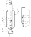
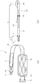
- 1 is an exemplary wearing state of the compression mechanism is worn on the wrist of the patient according to an embodiment of the present invention.
- Figure 3 is a block diagram showing the padding portion inner side contact surface and the support belt of another embodiment of the present invention.
- Figure 4 is a perspective view of the upper portion of the pressing mechanism.
- FIG. 5 is a perspective view of the lower portion of the pressing mechanism.
- FIG. 1 is an exemplary view of a state in which the compression mechanism 1 is worn on a wrist of a patient according to an embodiment of the present invention
- FIG. 2 is a view in which the compression mechanism 1 is unfolded.
- the pressure bar 1 is bent in the outer surface direction after a portion of the belt portion 10 passes through the switching ring 30 on the user's wrist so that the first coupling portion 21 and the second coupling portion 22 mutually Bonded by the first fastening support band 410 and fixed to the outer surface of the other end region of the belt portion 10 by the first fastening portion 41 and one end region by the second fastening support band 420.
- the pressing table 1 is double fixed locked.
- the pressing mechanism 1 includes a belt part 10, a coupling part 20, a switching ring 30, a fastening part 40, a padding part 50, an index pocket 60, and a fixing belt 70. .
- the belt portion 10 has a long band shape and is wound in contact with the user's wrist by the inner contact surface.
- the belt unit 10 includes a belt body 100, the length adjusting unit 110, the belt ring 120 and the switching ring band 130.
- the belt body 100 has a belt shape.
- the outer surface of the belt body 100 is equipped with a length adjusting unit 110 to adjust the length of the belt body 100.
- the length adjusting unit 110 includes a belt length adjusting ring 112 and a belt length adjusting band 114.
- the belt ring 120 is supported by the belt carrier band 121 fixedly mounted on the outer surface of the belt body 100.
- Belt length adjustment ring 112 has two adjacent rectangular ring shape.
- the belt length adjustment band 114 is fixed after passing through two adjacent rectangular rings of the belt length adjustment ring 112.
- Belt length adjustment band 114 is made of a fiber of a somewhat rigid material to maintain its shape even after passing through two adjacent rectangular rings of the belt length adjustment ring (112). Thereby, the length of the
- the conversion loop band 130 allows the conversion ring 30 to be supported.
- the coupling part 20 includes a first coupling part 21 and a second coupling part 22 which are sequentially attached to each other over a predetermined length of the outer surface from one end region of the belt body 100.
- Coupling portion 20 may have a Velcro support band that can be attached in the longitudinal direction of the belt body 100, the first coupling portion 21 and the second coupling portion 22 is a belt body 100 to the Velcro support band ) It is attached in the longitudinal direction.
- the first coupling part 21 and the second coupling part 22 may be constituted by a pair of velcro adhesively bonded when contacted with each other.
- the switching ring 30 is rotatably attached to the belt body 100 in the longitudinal direction.
- the switching ring 30 is a ring having a size that the belt body 100 can penetrate in an annular shape, and is rotatably supported with respect to the longitudinal direction of the surface of the belt body 100.
- the switching ring 30 is fixed to the other end region of the belt body 100 so as to pass and bend in one end region of the belt body 100 so that the first coupling portion 210 and the second coupling portion 220 are bonded to each other. Make it possible.
- the fastening part 40 bends the belt body 100 in the outer surface direction to form the first coupling part 21.
- the second coupling part 22 are in contact with each other and are bonded to each other, and the first coupling part 21 and the second coupling part 22 coupled to the surface of the belt body 100 are overlapped with each other.
- the fastening part 41 and the second fastening part 42 are positioned to be coupled to each other, and the first fastening part 41 and the second fastening part 42 are coupled to each other by double fastening.
- the first fastening portion 41 and the second fastening portion 42 are supported by the vent body 100 by the first fastening support band 410 and the second fastening support band 420, respectively.
- the fastening part 40 has a pair of locking means which are released from both sides along the width direction of the belt body 100.
- the first fastening portion 41 may be provided in a hook shape, but is not limited thereto.
- the second fastening portion 42 may be provided in a shape to receive and retain the hooking hook, but is not limited thereto.
- the fastening portion 40 for the double locking lock presses a pair of locking means with at least two fingers in the width direction of the belt body 100 so that the user does not release even when the user presses the back of the hand against a wall or other convex object. It is desirable to be able to release it.
- the fastening part 40 may be provided as long as the first fastening part 41 and the second fastening part 42 are coupled by fitting, but it is preferable that the fastening part 40 is not released by pressing in the outer surface direction of the belt main body 100.
- the fastening part 40 is fixed to the belt body 100 by the first fastening support band 410 and the second fastening support band 420, and the first fastening support band 410 and the second fastening support band 420.
- At least one of () is preferably elastically stretchable. If the user's wrist is thick, if one of the first fastening support band 410 and the second fastening support band 420 is not elastic, it can be elastically stretched because it may cause problems in blood circulation by excessively pressing the user's wrist. It is desirable to be provided.
- the padding part 50 is attached to the inner surface of the belt body 310. It is preferably provided with a fluffy material, and is provided to protect the wrist against the pressure of the belt body 100.
- the index pocket 60 is mounted on the inner contact surface of the belt body 100 in the region of the first coupling portion 21 with a transparent material. It is easy to identify the user by writing the name and information about the user in the index pocket 60.
- the fixed belt 70 includes a fixed belt body 71, a terminal fixing portion 72, a rotary ridge band 73, a fixed belt adjustment ring 74 and a fixed belt adjustment band 75.
- the fixed belt body 71 has a long band shape.
- the terminal fixing section 72 includes a first terminal fixing section 72-1 and a second terminal fixing section 72-2.
- the first end fixing portion 72-1 includes a locking rotation ring 72-11 and a rotation finger ring 72-12.
- the locking ring 72-11 is connected to the belt ring 120 and the rotating ring 72-12 is rotatably connected to the locking ring 72-11 by the rotating ring band 73. It is supported by the main body 71.
- Rotating paper ring 72-12 has a shape extending in the transverse direction of the projection pillar and the projection pillar end.
- One side of the locking rotary ring (72-11) is provided with an annular shape so as to receive the protruding pillar of the rotary ring (72-12) and to be caught in the extended portion.
- the locking rotation ring 72-11 may be connected and released by being caught by the belt ring 120 while being spaced apart by pressing a portion of the circular ring to be coupled and released.
- the hook rotating ring 72-11 may be provided to be released to facilitate evacuation of the user even in an emergency situation such as a fire.
- the second end fixing portion (72-2) is formed by the fixed belt control ring 74 and the fixed belt control band 75 to be described later to form a fixed belt body 71 in a ring shape.
- the second end fixing portion 72-2 may be fixed and fastened to the fixed structure.
- the fixed belt 70 has a fixed belt adjustment ring 74 and a fixed belt adjustment band 75 in a configuration that plays the same role as the length adjusting unit 110 in the longitudinal direction so as to adjust the length of the fixed belt 70.
- FIG 3 is a block diagram showing another embodiment of the inner contact surface and the fixing belt 370 of the padding unit 350 according to another embodiment of the present invention.
- the padding unit 350 is attached to the inner surface of the belt body 100 and the inner surface of the padding unit 350 may be provided in a well ventilated structure as shown in FIG.
- the padding part 350 may be provided with an elastic material therein so that the user may feel a fluffy feeling.
- the padding unit 350 may be well ventilated by applying a mesh fabric.
- the present invention is not limited thereto, and the padding part 350 may be made of thick elastic fibers in a well ventilated structure.
- the first coupling portion and the second coupling portion of the coupling portion 20 may be attached to the outer surface of the belt body 100 in succession, but the first coupling portion and the second coupling portion may not be connected to each other at a predetermined distance. It may be spaced apart.
- the fixing belt 370 is another embodiment of the fixing belt 370.
- the length adjusting part 110 is provided in an enlarged shape, and a rubber protrusion 373 is provided on the fixing belt 370 to be fixed in contact with the fixing belt adjusting ring 372.
- the fixing belt 370 to the structure such as a column through the first end fixing portion 72-1 through the one end region of the through portion at the end of the belt is sewn in a multi-layer structure in the second end fixing portion (72-2) ) Can be fixed.
- the terminal fixing section 72 may apply only one of the first terminal fixing section 72-1 and the second terminal fixing section 72-2, or may be applied in combination.
- the fixed belt body 371 may be composed of at least one elastic fabric or elastic fabric material. As a general waistband may be provided so that the latch and the locking hole is formed to adjust the length, but not limited to this can be fixed by changing to a suitable length.
- the second end fixing portion (72-2) is formed by the fixing belt adjusting ring 74 and the fixing belt adjusting band 75 to form a belt passing hole 380 of the fixed belt body 71 is annular. .
- the fixing belt body 371 is fixed. It is fastened and fixed to the frame under the bed. In this way, the fixing belt 370 may fix the pressing mechanism (1).
- the pressing mechanism 1 may be provided in the form of a glove.
- 4 is a perspective view of the upper connection portion 88 of the pressing mechanism (1).
- 5 is a perspective view of the lower connecting portion 89 of the pressing mechanism 1.
- the glove-type pressing mechanism 1 further includes a finger accommodation part 70, an upper connection part 80, a lower connection part 90, a length adjusting part 100, a support ring 110, and a support belt 120. ).
- a finger receiving portion 87 for receiving a patient's finger is connected by an upper connection portion 88 and a lower connection portion 89.
- the upper connection portion 88 connects the finger accommodation portion 87 and the padding portion 85 of the belt body 81 along the upper portion, that is, the back of the hand when the compression mechanism 1 is worn on the patient's hand.
- the lower connection part 89 connects the finger accommodation part 87 and the padding part 85 of the belt body 81 along the lower part, that is, the palm when worn on the patient's hand.
- the finger receiving portion 87 has a shape similar to that of a part of the mitten, but the portion formed by the upper connecting portion 88 and the lower connecting portion 89 does not surround all of the patient's hand like the mitten, and the patient's hand is outside. To be exposed. As a result, unlike the mitten, ventilation can be smoothly performed by the finger of the patient accommodated in the finger accommodation portion 87.
- An index pocket 86 made of a transparent material may be provided on the inner surface of the belt body 81. It is possible to easily identify the patient by writing the name and information about the patient in the index pocket 86.
- the support ring 91 provided on the belt body 81 is connected to the locking rotation ring 72 of the support belt 70.
- the support belt 70 may be connected to a support that may be fixed such as a bed column or a chair of the patient to support the belt body 81 in which the patient's wrist is double fixed and locked. Since the length of the support belt 70 may need to be adjusted according to the position of the patient, the belt control ring 75 and the fixed belt adjustment band 76 are provided on the outer surface of the support belt 70 to adjust the length.
- the internal contact surface of the first padding portion 85-1 connected to the belt body 81 is shown.
- the second padding portion 85-2 connected to the finger receiving portion 87 and the upper connecting portion 88 is connected to the inner contact surface of the first padding portion 85-1.
- the second padding portion 85-2 may be provided with an elastic material inside the padding portion 50, so that the patient may feel fluffy.
- the upper portion of the connection portion 88 and the lower portion connected to the body 81 and the lower portion formed by the 89 can be well ventilated, but the finger receiving portion 87 is more preferably ventilated by applying a mesh fabric .
- the finger receiving portion 87, the upper connecting portion 88 and the second padding portion 85-2 are integrally formed. However, the finger receiving portion 87 and the second padding portion 85-2 are separated, and the velcro is formed at one side and the other side and is connected.
- the shape of the upper connecting portion 88 may be a shape such that a part of the patient's hand is exposed to the outside. As a result, ventilation can be smoothly performed by the patient's hand accommodated in the finger accommodation part 87.
- the length adjusting part 90 may be provided at an outer surface area of the upper connection part 88. Thereby, the length of the second padding portion 85-2 connected to the padding portion 95 of the finger receiving portion 87 and the belt main body 81 is adjusted so that the patient's hand is free to move so that the finger receiving portion 87 does not escape. Can be. For example, in the case of a small hand patient, the length of the length adjusting unit 90 can be reduced.
- the pressing mechanism 1 of FIG. 5 has a belt body 81 which has a long belt shape and is wound in contact with the wrist of the patient by the inner contact surface.
- the belt main body 81 has a first velcro portion 82-1 and a second velcro portion 82-2 which can be attached to each other sequentially from a region of one end of the belt body 81 to a predetermined length of the outer surface.
- Velcro 82 made of is attached.
- Velcro 82 may have a Velcro support band that can be attached in the longitudinal direction of the belt body 81, the first Velcro portion (82-1) and the second Velcro portion (82-2) is a belt on the Velcro support band
- the main body 81 may be attached in the longitudinal direction.
- the first Velcro portion 82-1 and the second Velcro portion 82-2 are made up of hook-shaped small fiber hooks and hooks that are entangled so that the small fiber hooks are caught. do.
- the belt main body 81 is fixed to the other end region of the belt main body 81 and passed and bent in one end region of the belt main body 81 so that the first Velcro portion 82-1 and the second Velcro portion 82-2 are Is attached rotatably with respect to the longitudinal direction of the belt main body 81.
- the conversion ring 83 has a rectangular ring shape having a size that the belt body 81 can penetrate into a rectangular ring shape, and may be rotatably supported with respect to the longitudinal direction of the surface of the belt body 81.
- the belt main body 81 has a first buckle portion 82-1 fixed to an outer surface of the other end region of the belt main body 81 and a first buckle portion 84-1 fixed to an area of the Velcro 82-2. And a hook buckle 84 having a second buckle portion 84-2 engaged with and fastened thereto.
- the belt main body 81 is bent in the outer surface direction so that the first Velcro portion 82-1 and the second Velcro The parts 82-2 are in contact with each other to be bonded to each other.
- the first velcro portion 82-1 and the second velcro portion 82-2 are bonded to each other, the first velcro portion 82-1 and the second velcro portion coupled to the surface of the belt main body 81.
- the first buckle portion 84-1 and the second buckle portion 84-2 are positioned so that the first buckle portion 84-1 and the second buckle portion 84-2 can be engaged in the region overlapping with the region of 82-2. 1) and the second buckle portion 84-2 are combined to form a double fixed lock.
- the hook buckle 84 has a pair of hooks released from both sides along the width direction of the belt body 81.
- the first buckle portion 84-1 may be provided in a hook shape, but is not limited thereto.
- the second buckle portion 84-2 may be provided in a shape to receive and retain the hook hook, but is not limited thereto.
- the hook buckle 84 which has a double locking lock, presses a pair of hooks in the width direction of the belt main body 81 with at least two fingers so that the patient does not release even when the patient presses the back of the hand against a wall or other convex object. It is desirable to be able to be released.
- the hook buckle 84 may be provided that the first buckle portion 84-1 and the second buckle portion 84-2 are engaged by fitting, but are not released by pressing in the outer surface direction of the belt body 81. desirable.
- Hook buckle 84 is fixed to the belt body 81 by the first fixing band and the second fixing band (84-11, 84-21), the first fixing band and the second fixing band (84-11, 84) At least one of -21 may be elastically stretchable. If the patient's wrist is thick, if the first fixing band and the second fixing band (84-11, 84-21) are not stretchy, the patient's wrist may be excessively pressurized, which may cause problems with blood circulation and thus elasticity is possible. It is preferable to provide.
- the length adjustment unit 90 may be provided on the belt body 81 to correspond to the thickness of the wrist of the patient.
- the length adjusting part 90 may be provided with a length adjusting ring 90-1 and a length adjusting belt 90-2.
- the length adjusting ring 90-1 may have two adjacent rectangular ring shapes.
- the length adjustment belt 90-2 is fixed after passing two adjacent rectangular rings of the length adjustment ring 90-1.
- the length adjustment belt 90-1 is made of a fiber of a somewhat rigid material and maintains its shape even after passing through two adjacent rectangular rings of the length adjustment ring 90-1. Thereby, the length of the belt body 81 can be adjusted to suit the thickness of the wrist of the patient.
- the padding portion 85 is attached to the inner surface of the belt body 10 and the inner surface of the padding portion 50 may be provided in a well ventilated structure. Padding portion 85 is provided with an elastic material inside the patient can receive a fluffy feeling. In addition, the padding portion 85 may be well ventilated by applying a mesh fabric. However, the present invention is not limited thereto, and the padding part 85 may be made of thick elastic fibers in a well ventilated structure.
- Ventilation can be achieved by the portion formed by the upper connecting portion 88 and the lower connecting portion 89 connected to the belt body 81, but in the hot case, sweat may occur in the hand of the patient accommodated in the finger accommodation portion 87, It may be made of a structure and a material that can be good.
- at least a part of the ventilation area 87-1 of the finger receiving part 87 is made of a structure and a material such that the degree of ventilation is higher than that of the remaining area, and at least part of the ventilation openings 87-2 are provided in summer. If the temperature is high, such as opening and closing the ventilation opening (87-2) may be made to close in winter. Patients who can do self-harm usually live in the room, so they may not be sensitive to outside temperature. Therefore, it may be made of a material that is well ventilated at the time of manufacturing the compression mechanism (1) or may be made of a structure that is well ventilated.
- the upper connecting portion 88 and the lower connecting portion 89 is connected to the belt body 81, and the portion formed is always exposed to the outside, such as a cut portion, but the opening and closing portion, such as the ventilation opening and closing portion 87-2, is provided and closed when cold. It may be prepared to protect the hand of the patient.
- the pressing mechanism 1 is interposed between at least one of the first coupling portion 21 and the second coupling portion 22 and the first coupling portion 41 and the second coupling portion 42 to sense the release of the coupling. It further comprises a release detecting sensor (91).
- the first coupling part 41 and the second coupling part 42 release the first coupling and the first coupling part 21 and the second coupling part 22 are separated. This is the case when the secondary coupling is released. Therefore, detecting the case where the coupling of the first fastening portion 41 and the second fastening portion 42 is released is advantageous to prevent the self-harming behavior of the patient, so that the release detecting sensor 91 is connected to the first coupling portion 21.
- first fastening part 41 and the second fastening part 42 are interposed between the first fastening part 41 and the second fastening part 42 rather than between the second coupling part 22. More preferably, it is interposed between the first coupling portion 21 and the second coupling portion 22 and between the first coupling portion 41 and the second coupling portion 42.
- the release detecting sensor 91 is provided as a magnetic sensor and is installed at both sides between the first coupling part 21 and the second coupling part 22 and between the first fastening part 41 and the second fastening part 42. In the case of abnormal separation, the release detection signal may be transmitted to the central controller 2.
- the first coupling portion 21, the second coupling portion 22 and the first fastening portion 41, the second fastening portion 42 using the patient's wrist while pressing the restraint It may be provided in the form of restraining the wrist by electric.
- a fire signal may be detected or received from the outside, and may be provided to release the restraint of the pressing mechanism 1 when the fire signal is detected and received.
- the locking unit may be provided to release the engagement by the electric in the engaged state.
- the belt ring 90 may be provided to be open and closed.
- the pressure mechanism 1 it is possible to prevent the patient from releasing the strapping state arbitrarily and to maintain a durable strapping force so as to surely limit the user's hand, thereby preventing the patient's self-injury.
- the compression mechanism can be maintained firmly and breathability can be improved to provide cleanliness and comfort. As the manager can see that the patient's strapping is released, the self-harm prevention effect of the patient can be further improved.
Landscapes
- Health & Medical Sciences (AREA)
- General Health & Medical Sciences (AREA)
- Life Sciences & Earth Sciences (AREA)
- Nursing (AREA)
- Veterinary Medicine (AREA)
- Public Health (AREA)
- Animal Behavior & Ethology (AREA)
- Biomedical Technology (AREA)
- Vascular Medicine (AREA)
- Heart & Thoracic Surgery (AREA)
- Engineering & Computer Science (AREA)
- Orthopedic Medicine & Surgery (AREA)
- Child & Adolescent Psychology (AREA)
- Business, Economics & Management (AREA)
- Emergency Management (AREA)
- Physics & Mathematics (AREA)
- General Physics & Mathematics (AREA)
- Orthopedics, Nursing, And Contraception (AREA)
Abstract
Description
Claims (8)
- 자해방지용 압박기구에 있어서,긴 띠형상을 가지고 내측접촉표면으로 사용자의 손목에 접촉하여 감기는 벨트부와;상기 벨트부의 일단부 영역으로부터 외표면의 소정 길이구간에 걸쳐 순차적으로 부착된 상호 접착 가능한 제1결합부와 제2결합부를 갖는 결합부와;상기 벨트부의 타단부 영역에 고정되어 상기 벨트부의 일단부 영역에 통과 및 절곡되어 상기 제1결합부와 상기 제2결합부가 상호 접착 가능하게 하는 전환고리와;상기 타단부 영역의 외표면에 고정되는 제1체결부와 상기 결합부의 영역에 고정되어 상기 제1체결부와 맞물려 체결되는 제2체결부를 갖는 체결부를 포함하는 것을 특징으로 하는 자해방지용 압박기구.
- 제 1 항에 있어서,상기 체결부는 상기 벨트부의 폭방향을 따라 양측에서 가압해제되는 한 쌍의 걸림수단을 갖는 것을 특징으로 하는 자해방지용 압박기구.
- 제 1 항에 있어서,상기 체결부는 고정밴드에 의해 상기 벨트부에 고정되며, 상기 고정밴드 중 적어도 하나는 탄성적으로 신축 가능한 것을 특징으로 하는 자해방지용 압박기구.
- 제 1 항에 있어서,상기 사용자의 손가락을 수용하는 손가락수용부와;상기 손가락수용부와 상기 벨트부를 상기 사용자의 손의 상부 및 하부를 따라 각각 연결하는 상부연결부와 하부연결부를 더 포함하는 것을 특징으로 하는 재해방지용 압박기구.
- 제 1 항에 있어서,상기 벨트부와 연결되며 고정구조물에 고정 및 체결되도록 하는 고정벨트를 더 포함하는 것을 특징으로 하는 재해방지용 압박기구.
- 제 5 항에 있어서,상기 고정벨트는,긴 띠형상을 갖는 고정벨트본체;상기 고정벨트본체의 길이를 조절하는 고정벨트조절고리; 및상기 고정벨트본체에 지지되며 상기 벨트부와 상기 고정구조물에 고정 및 체결되는 말단고정부를 갖는 것을 특징으로 하는 자해방지용 압박기구.
- 제 6 항에 있어서,상기 고정벨트본체는 외표면의 소정 구간에 고무돌기가 형성되는 것을 특징으로 하는 자해방지용 압박기구.
- 제 1 항에 있어서,상기 제1결합부와 상기 제2결합부 및 상기 제1체결부와 상기 제2체결부 중 적어도 하나의 사이에 개재되어 결합해제를 감지하는 해제감지센서를 더 포함하는 것을 특징으로 하는 자해방지용 압박기구.
Priority Applications (1)
| Application Number | Priority Date | Filing Date | Title |
|---|---|---|---|
| US16/980,662 US20210022906A1 (en) | 2018-03-14 | 2019-03-14 | Compression apparatus for preventing self-harm |
Applications Claiming Priority (2)
| Application Number | Priority Date | Filing Date | Title |
|---|---|---|---|
| KR1020180029844A KR101937956B1 (ko) | 2018-03-14 | 2018-03-14 | 자해방지용 압박기구 |
| KR10-2018-0029844 | 2018-03-14 |
Publications (1)
| Publication Number | Publication Date |
|---|---|
| WO2019177404A1 true WO2019177404A1 (ko) | 2019-09-19 |
Family
ID=65027570
Family Applications (1)
| Application Number | Title | Priority Date | Filing Date |
|---|---|---|---|
| PCT/KR2019/002989 Ceased WO2019177404A1 (ko) | 2018-03-14 | 2019-03-14 | 자해방지용 압박기구 |
Country Status (3)
| Country | Link |
|---|---|
| US (1) | US20210022906A1 (ko) |
| KR (1) | KR101937956B1 (ko) |
| WO (1) | WO2019177404A1 (ko) |
Families Citing this family (7)
| Publication number | Priority date | Publication date | Assignee | Title |
|---|---|---|---|---|
| KR101937956B1 (ko) * | 2018-03-14 | 2019-01-14 | 박성용 | 자해방지용 압박기구 |
| KR102257435B1 (ko) * | 2019-06-03 | 2021-05-27 | 한한수 | 관절 굽힘 제한 장치 |
| KR102292315B1 (ko) * | 2019-06-10 | 2021-08-24 | 건양대학교산학협력단 | 신축 가능한 환자 억제 장치 |
| KR102292317B1 (ko) * | 2019-07-01 | 2021-08-24 | 건양대학교산학협력단 | 환자 모니터링이 가능한 억제대 |
| FR3116186B1 (fr) * | 2020-11-19 | 2022-11-18 | Decathlon Sa | Ensemble vestimentaire pour la pratique d’un sport d’hiver |
| CN113545907B (zh) * | 2021-07-21 | 2023-01-03 | 李贤勇 | 医疗束缚手的机构及束缚方法 |
| WO2026064698A1 (en) * | 2024-09-23 | 2026-03-26 | Stryker Corporation | Patient restraint system including restraints with wireless emitters |
Citations (6)
| Publication number | Priority date | Publication date | Assignee | Title |
|---|---|---|---|---|
| KR200382292Y1 (ko) * | 2005-01-31 | 2005-04-18 | 천숙자 | 치매환자용 보호대 |
| JP2008018187A (ja) * | 2006-07-14 | 2008-01-31 | Chest M I Inc | サポートバンド |
| KR101043802B1 (ko) * | 2006-07-05 | 2011-07-11 | 천숙자 | 치매 환자용 보호구 |
| CN203138779U (zh) * | 2013-02-08 | 2013-08-21 | 复旦大学附属华山医院 | 掌型约束固定器具 |
| KR200476505Y1 (ko) * | 2013-06-20 | 2015-03-05 | 김성래 | 손목 움직임 억제대 |
| KR101937956B1 (ko) * | 2018-03-14 | 2019-01-14 | 박성용 | 자해방지용 압박기구 |
Family Cites Families (6)
| Publication number | Priority date | Publication date | Assignee | Title |
|---|---|---|---|---|
| US4422455A (en) * | 1981-08-04 | 1983-12-27 | Danek Medical, Inc. | Restraining device |
| US4628925A (en) * | 1986-02-24 | 1986-12-16 | Heelbo, Inc. | Quick-release limb holder apparatus |
| US6656141B1 (en) * | 1995-02-17 | 2003-12-02 | Tony Reid | Multiple sleeve method and apparatus for treating edema and other swelling disorders |
| US7173437B2 (en) * | 2004-06-10 | 2007-02-06 | Quantum Applied Science And Research, Inc. | Garment incorporating embedded physiological sensors |
| KR200466868Y1 (ko) | 2011-07-01 | 2013-05-10 | 변태경 | 환자용 보호장갑 |
| KR101361158B1 (ko) | 2012-11-30 | 2014-02-12 | 이승민 | 손가락의 욕창방지기능이 구비되는 치매환자용 보호복 |
-
2018
- 2018-03-14 KR KR1020180029844A patent/KR101937956B1/ko active Active
-
2019
- 2019-03-14 US US16/980,662 patent/US20210022906A1/en not_active Abandoned
- 2019-03-14 WO PCT/KR2019/002989 patent/WO2019177404A1/ko not_active Ceased
Patent Citations (6)
| Publication number | Priority date | Publication date | Assignee | Title |
|---|---|---|---|---|
| KR200382292Y1 (ko) * | 2005-01-31 | 2005-04-18 | 천숙자 | 치매환자용 보호대 |
| KR101043802B1 (ko) * | 2006-07-05 | 2011-07-11 | 천숙자 | 치매 환자용 보호구 |
| JP2008018187A (ja) * | 2006-07-14 | 2008-01-31 | Chest M I Inc | サポートバンド |
| CN203138779U (zh) * | 2013-02-08 | 2013-08-21 | 复旦大学附属华山医院 | 掌型约束固定器具 |
| KR200476505Y1 (ko) * | 2013-06-20 | 2015-03-05 | 김성래 | 손목 움직임 억제대 |
| KR101937956B1 (ko) * | 2018-03-14 | 2019-01-14 | 박성용 | 자해방지용 압박기구 |
Also Published As
| Publication number | Publication date |
|---|---|
| US20210022906A1 (en) | 2021-01-28 |
| KR101937956B1 (ko) | 2019-01-14 |
Similar Documents
| Publication | Publication Date | Title |
|---|---|---|
| KR101937956B1 (ko) | 자해방지용 압박기구 | |
| US9408573B2 (en) | Patient interface for reusable optical sensor | |
| JP3609404B2 (ja) | 健康モニタリングシステム | |
| US7926120B2 (en) | Isolation garment and foot ware | |
| GB2261290A (en) | Physiological monitoring | |
| KR100816778B1 (ko) | 치매환자 보호용 환자복 | |
| US20180220724A1 (en) | Patient Mittens | |
| US4524768A (en) | Restraint garment | |
| CN210811879U (zh) | 一种一体式约束带 | |
| CN210872329U (zh) | 一种自动报警约束手套 | |
| CN215192776U (zh) | 一种约束装置 | |
| KR102257435B1 (ko) | 관절 굽힘 제한 장치 | |
| US20050121041A1 (en) | Human extremity restraint | |
| US11654041B2 (en) | System for covering and visually distinguishing an injured limb | |
| KR20230100079A (ko) | 치매환자용 안전 손가락 보호대 | |
| CN211911936U (zh) | 一种有效固定双手的约束装置 | |
| CN221431326U (zh) | 一种约束手套 | |
| KR200459974Y1 (ko) | 치매 환자용 장갑 | |
| CN214632557U (zh) | 一种约束手套 | |
| US4917109A (en) | Patient restraint garment | |
| CN219614159U (zh) | 一种约束手套 | |
| CN217448181U (zh) | 一种约束装置 | |
| CN222109397U (zh) | 一种病员护理服装 | |
| CN216651401U (zh) | 防护服 | |
| CN214318149U (zh) | 一种小儿皮试保护装置 |
Legal Events
| Date | Code | Title | Description |
|---|---|---|---|
| 121 | Ep: the epo has been informed by wipo that ep was designated in this application |
Ref document number: 19768249 Country of ref document: EP Kind code of ref document: A1 |
|
| NENP | Non-entry into the national phase |
Ref country code: DE |
|
| 122 | Ep: pct application non-entry in european phase |
Ref document number: 19768249 Country of ref document: EP Kind code of ref document: A1 |
|
| 32PN | Ep: public notification in the ep bulletin as address of the adressee cannot be established |
Free format text: NOTING OF LOSS OF RIGHTS PURSUANT TO RULE 112(1) EPC (EPO FORM 1205A DATED 19/04/2021) |
|
| 122 | Ep: pct application non-entry in european phase |
Ref document number: 19768249 Country of ref document: EP Kind code of ref document: A1 |