WO2019176546A1 - Air-conditioning control device, air-conditioning system, air-conditioning control method, and program - Google Patents
Air-conditioning control device, air-conditioning system, air-conditioning control method, and program Download PDFInfo
- Publication number
- WO2019176546A1 WO2019176546A1 PCT/JP2019/007707 JP2019007707W WO2019176546A1 WO 2019176546 A1 WO2019176546 A1 WO 2019176546A1 JP 2019007707 W JP2019007707 W JP 2019007707W WO 2019176546 A1 WO2019176546 A1 WO 2019176546A1
- Authority
- WO
- WIPO (PCT)
- Prior art keywords
- saving operation
- energy
- air
- air conditioner
- room
- Prior art date
Links
Images


Classifications
-
- F—MECHANICAL ENGINEERING; LIGHTING; HEATING; WEAPONS; BLASTING
- F24—HEATING; RANGES; VENTILATING
- F24F—AIR-CONDITIONING; AIR-HUMIDIFICATION; VENTILATION; USE OF AIR CURRENTS FOR SCREENING
- F24F11/00—Control or safety arrangements
- F24F11/30—Control or safety arrangements for purposes related to the operation of the system, e.g. for safety or monitoring
- F24F11/46—Improving electric energy efficiency or saving
-
- F—MECHANICAL ENGINEERING; LIGHTING; HEATING; WEAPONS; BLASTING
- F24—HEATING; RANGES; VENTILATING
- F24F—AIR-CONDITIONING; AIR-HUMIDIFICATION; VENTILATION; USE OF AIR CURRENTS FOR SCREENING
- F24F11/00—Control or safety arrangements
- F24F11/62—Control or safety arrangements characterised by the type of control or by internal processing, e.g. using fuzzy logic, adaptive control or estimation of values
- F24F11/63—Electronic processing
- F24F11/64—Electronic processing using pre-stored data
-
- F—MECHANICAL ENGINEERING; LIGHTING; HEATING; WEAPONS; BLASTING
- F24—HEATING; RANGES; VENTILATING
- F24F—AIR-CONDITIONING; AIR-HUMIDIFICATION; VENTILATION; USE OF AIR CURRENTS FOR SCREENING
- F24F11/00—Control or safety arrangements
- F24F11/62—Control or safety arrangements characterised by the type of control or by internal processing, e.g. using fuzzy logic, adaptive control or estimation of values
- F24F11/63—Electronic processing
- F24F11/65—Electronic processing for selecting an operating mode
-
- G—PHYSICS
- G05—CONTROLLING; REGULATING
- G05B—CONTROL OR REGULATING SYSTEMS IN GENERAL; FUNCTIONAL ELEMENTS OF SUCH SYSTEMS; MONITORING OR TESTING ARRANGEMENTS FOR SUCH SYSTEMS OR ELEMENTS
- G05B13/00—Adaptive control systems, i.e. systems automatically adjusting themselves to have a performance which is optimum according to some preassigned criterion
- G05B13/02—Adaptive control systems, i.e. systems automatically adjusting themselves to have a performance which is optimum according to some preassigned criterion electric
- G05B13/04—Adaptive control systems, i.e. systems automatically adjusting themselves to have a performance which is optimum according to some preassigned criterion electric involving the use of models or simulators
- G05B13/048—Adaptive control systems, i.e. systems automatically adjusting themselves to have a performance which is optimum according to some preassigned criterion electric involving the use of models or simulators using a predictor
-
- F—MECHANICAL ENGINEERING; LIGHTING; HEATING; WEAPONS; BLASTING
- F24—HEATING; RANGES; VENTILATING
- F24F—AIR-CONDITIONING; AIR-HUMIDIFICATION; VENTILATION; USE OF AIR CURRENTS FOR SCREENING
- F24F2110/00—Control inputs relating to air properties
- F24F2110/10—Temperature
-
- F—MECHANICAL ENGINEERING; LIGHTING; HEATING; WEAPONS; BLASTING
- F24—HEATING; RANGES; VENTILATING
- F24F—AIR-CONDITIONING; AIR-HUMIDIFICATION; VENTILATION; USE OF AIR CURRENTS FOR SCREENING
- F24F2120/00—Control inputs relating to users or occupants
- F24F2120/20—Feedback from users
Definitions
- Embodiments described herein relate generally to an air conditioning control device, an air conditioning system, an air conditioning control method, and a program.
- an air conditioner is installed in a room such as an office.
- this air conditioner is required to be operated so as to save energy (hereinafter referred to as an energy saving operation of the air conditioner).
- the energy-saving operation of the air conditioner is performed, for example, by setting an upper limit for power consumption (save operation) or by relaxing the set temperature and air volume of the air conditioner. Further, when a plurality of air conditioners are installed, energy saving can also be realized by shifting the output timing of the plurality of air conditioners (peak shift) or the like.
- the air conditioner is operated with less power than is normally required, so the indoor comfort gradually decreases.
- the occupant can save energy of the air conditioner by operating, for example, a remote controller. Although the operation can be canceled (stopped), it is complicated to perform an operation for canceling the energy saving operation.
- the energy-saving operation is automatically canceled after the start of the energy-saving operation of the air conditioner until the occupant feels uncomfortable.
- the problem to be solved by the present invention is that an air conditioning control device, an air conditioning system, and an air conditioning control method capable of releasing the energy saving operation before the occupant feels uncomfortable after starting the energy saving operation of the air conditioner And providing a program.
- the air-conditioning control apparatus includes model storage means, acquisition means, and control means.
- the model storage means includes a time until the energy-saving operation is canceled by a resident after the energy-saving operation of the air conditioner installed in the room is started, and the indoor space when the energy-saving operation is canceled.
- Stores a discomfort probability model in which an estimate of the discomfort level of the occupant for the relationship with the air conditioning state is defined.
- the acquisition means acquires the current air conditioning state in the room during the energy saving operation of the air conditioner.
- the control means based on the degree of discomfort of the occupants obtained by applying the acquired air conditioning state and the elapsed time from the start of the energy-saving operation to the present to the discomfort probability model, Cancel energy-saving operation.
- FIG. 1 is a figure showing an example of the composition of the air-conditioning system containing the air-conditioning control device concerning one embodiment.
- FIG. 2 is a diagram illustrating an example of a hardware configuration of the air conditioning control device.
- FIG. 3 is a diagram illustrating the relationship between the energy saving operation and the indoor air conditioning state when the operation mode of the air conditioner is the cooling mode.
- FIG. 4 is a diagram illustrating an example of a data structure of log data.
- FIG. 5 is a flowchart illustrating an example of a processing procedure of log data acquisition processing.
- FIG. 6 is a flowchart illustrating an example of a processing procedure of model construction processing.
- FIG. 7 is a diagram in which the relationship between the energy saving operation time and the average room temperature is visualized as a plane scatter diagram.
- FIG. 1 is a figure showing an example of the composition of the air-conditioning system containing the air-conditioning control device concerning one embodiment.
- FIG. 2 is a diagram illustrating an example of a hardware
- FIG. 8 is a diagram in which the relationship between the energy saving operation time obtained for each energy saving operation and the average room temperature is visualized as a plane scatter diagram.
- FIG. 9 is a diagram showing threshold lines on a plane scatter diagram.
- FIG. 10 is a flowchart illustrating an example of a processing procedure of the discomfort degree estimation process.
- FIG. 11 is a diagram in which the relationship between the energy saving operation time and the dispersion value obtained for each energy saving operation is visualized as a plane scatter diagram together with a threshold line.
- FIG. 12 is a diagram for explaining an example of the configuration of the air conditioning control device 10 when data other than room temperature is used.
- FIG. 13 is a diagram for explaining an air conditioner that can control a plurality of indoor units with one refrigerant system.
- FIG. 1 shows an example of the configuration of an air conditioning system including an air conditioning control device according to the first embodiment.
- the air conditioning system includes an air conditioning control device 10 and an air conditioner connected to the air conditioning control device 10 via a transmission path.
- the air conditioner includes an indoor unit that is installed in a room (space) such as a room in a building and performs air conditioning of the room.
- a room space
- the air conditioning system will be described as including air conditioners 30A and 30B installed in the room 20, but the air conditioning system includes one air conditioner. It may be three or more.
- the room 20 may be the entire facility such as a house or a building, or may be a space in the facility that is distinguished by a floor, an inner wall, and the like.
- the air conditioner 30A performs air conditioning of the room 20 according to the set value of the air conditioning setting input via the remote controller 40A by, for example, a person in the room 20 (hereinafter referred to as a resident).
- a room temperature meter 50A for measuring the temperature (room temperature) of the room 20 is connected to the air conditioner 30A.
- the air conditioner 30A performs air conditioning based on the room temperature measured by the room temperature meter 50A.
- the air conditioner 30B performs air conditioning of the room 20 according to the set value of the air conditioning setting input by the occupant via the remote control 40B, for example.
- a room temperature meter 50B is connected to the air conditioner 30B, and the air conditioner 30B performs air conditioning based on the room temperature measured by the room temperature meter 50B.
- the above-described room temperature meters 50A and 50B may be incorporated in the air conditioners 30A and 30B, respectively, or may be arranged at different positions in the room 20. Furthermore, the room temperature meters 50A and 50B may be the same room temperature meter.
- the air conditioning control device 10 is a device for controlling the operation of the air conditioners 30A and 30B (that is, controlling the air conditioning of the room 20), and is provided in a management room of a building, for example.
- the air conditioning control device 10 is a device such as a BEMS (Building Energy Management System) that is introduced for the purpose of, for example, a building administrator grasping the air conditioning state of the room 20 or changing the settings of the air conditioners 30A and 30B.
- BEMS Building Energy Management System
- other equipment used in the air conditioning system may be used.
- the air conditioning control device 10 includes a log data acquisition unit 11, a log data storage unit 12, a model construction unit 13, a model storage unit 14, a discomfort degree estimation unit 15, and an operation control unit 16.
- the log data acquisition unit 11 acquires log data including the operation status of the air conditioners 30A and 30B and the history of the air condition of the room 20 from each of the air conditioners 30A and 30B.
- the log data is acquired at predetermined intervals and stored in the log data storage unit 12.
- the log data storage unit 12 stores log data including past operating conditions of the air conditioners 30A and 30B and past air conditioning conditions of the room 20.
- each of the air conditioners 30A and 30B is capable of energy-saving operation.
- the energy saving operation in the present embodiment is an operation of an air conditioner that realizes energy saving (that is, the air conditioning system operates with less energy), and includes, for example, the operation of the air conditioner in a state where the air conditioning setting is relaxed.
- the air conditioning setting is relaxed means that when the operation mode of the air conditioner is the cooling mode, the set temperature of the air conditioner is raised, and the operation mode of the air conditioner is the heating mode. In the case of the mode, it includes that the set temperature of the air conditioner is lowered.
- “releasing the air conditioning setting” may include, for example, reducing the air volume output from the air conditioner.
- the operation other than the energy saving operation is referred to as normal operation for convenience.
- the energy saving operation of each of the air conditioners 30A and 30B may be started in accordance with, for example, an operation on the remote controls 40A and 40B by a resident, or may be started according to a predetermined condition or the like.
- the conditions for starting the energy saving operation include, for example, that a predetermined time has been reached and that the room 20 has reached a predetermined temperature.
- the operation mode of each of the air conditioners 30A and 30B is the cooling mode
- the energy saving operation is started when the set temperature of the air conditioners 30A and 30B is in a time zone that tends to be raised by the occupants. May be.
- the energy saving operation is performed when the set temperature of the air conditioners 30A and 30B tends to be lowered by the occupants. May be started.
- the time zone in which the set temperature tends to increase and the time zone in which the set temperature tends to decrease may be specified from, for example, log data stored in the log data storage unit 12 or other data.
- the air conditioner is operated with less energy (electric power) than is normally required, so if the energy saving operation is continued, the indoor comfort gradually decreases, residents will eventually feel uncomfortable.
- the model construction unit 13 constructs a discomfort probability model based on the log data stored in the log data storage unit 12.
- the discomfort probability model is the degree of discomfort of the occupants in the room 20 based on the elapsed time since the start of the energy-saving operation and the air conditioning state of the room 20 (the degree that the occupants feel uncomfortable in the room 20). ) Is a model used for estimating.
- the discomfort probability model constructed by the model construction unit 13 is stored in the model storage unit 14. Details of the discomfort probability model will be described later.
- the discomfort degree estimation unit 15 estimates (evaluates) the discomfort level of the occupants using the discomfort probability model stored in the model storage unit 14 during the energy saving operation of the air conditioners 30A and 30B.
- the operation control unit 16 cancels the energy-saving operation of the air conditioners 30A and 30B based on the discomfort level estimated by the discomfort level estimation unit 15. In this case, the operation control unit 16 changes the direction so as to increase the air conditioning settings (for example, set temperature) of the air conditioners 30A and 30B.
- the air conditioning settings for example, set temperature
- increasing air conditioning settings is the opposite of “relaxing air conditioning settings” described above.
- the air conditioner when the operation mode of the air conditioner is the cooling mode, the air conditioner This includes that the set temperature is lowered, and that the set temperature of the air conditioner is raised when the operation mode of the air conditioner is the heating mode.
- the building administrator can display the log data stored in the log data storage unit 12 on the display device of the air conditioning control device 10 by operating the air conditioning control device 10. Further, the building manager can change the set value of the air conditioning setting of the air conditioners 30A and 30B or start the energy saving operation by operating the air conditioning control device 10 in the same manner as the remote controls 40A and 40B described above. is there.
- FIG. 2 shows an example of the hardware configuration of the air conditioning control device 10 according to the present embodiment.
- the air conditioning control device 10 includes a CPU 101, a nonvolatile memory 102, a main memory 103, a communication device 104, and the like.
- the CPU 101 is a hardware processor that controls the operation of various components in the air conditioning control device 10.
- the CPU 101 executes various programs loaded from the nonvolatile memory 102 that is a storage device to the main memory 103.
- the program executed by the CPU 101 includes an operating system and an application program (hereinafter referred to as an air conditioning control program) for controlling the operation of the air conditioners 30A and 30B.
- the CPU 101 also executes a basic input / output system (BIOS), which is a program for hardware control, for example.
- BIOS basic input / output system
- the air conditioning control device 10 is described as including the CPU 101, but the air conditioning control device 10 may include a processor or controller other than the CPU 101 as long as the above-described program can be executed. .
- some or all of the log data acquisition unit 11, the model construction unit 13, the discomfort degree estimation unit 15, and the operation control unit 16 illustrated in FIG. 1 cause the CPU 101 to execute an air conditioning control program. That is, it shall be realized by software. Part or all of these units 11, 13, 15 and 16 may be realized by hardware such as an IC (Integrated Circuit), or may be realized as a combination configuration of software and hardware.
- IC Integrated Circuit
- the log data storage unit 12 and the model storage unit 14 illustrated in FIG. 1 are realized by a storage device such as the nonvolatile memory 102 described above.
- the communication device 104 is a device configured to execute, for example, wired or wireless communication with an external device.
- the air conditioning control device 10 has been described as including the CPU 101, the nonvolatile memory 102, the main memory 103, and the communication device 104. However, the air conditioning control device 10 displays log data as described above. A display device and an input device for changing the setting values of the air conditioning settings of the air conditioners 30A and 30B may be further provided.
- FIG. 3 shows the relationship between the energy saving operation and the air conditioning state of the room 20 when the operation mode of the air conditioners 30A and 30B is the cooling mode.
- the upper part of FIG. 3 shows the transition of the set temperature of the air conditioner 30A in a visualized manner.
- the first energy saving operation flag in the upper part of FIG. 3 indicates whether the air conditioner 30A is in the energy saving operation, as will be described later.
- the middle part of FIG. 3 visualizes and shows the transition of the set temperature of the air conditioner 30B.
- the second energy-saving operation flag in the middle part of FIG. 3 indicates whether the air conditioner 30B is in the energy-saving operation to the amount described later.
- the lower part of FIG. 3 visualizes and shows the transition of the average value of the temperature (room temperature) of the room 20 as the set temperatures of the air conditioners 30A and 30B are raised and lowered.
- the average value of the room temperature demonstrated in FIG. 3 etc. shall be the average value of the temperature distribution of the room
- the energy saving operation of the air conditioner 30A is started at 10:30 when the temperature of the room 20 is lowered by the air conditioning performed by the air conditioners 30A and 30B (that is, the setting of the air conditioner 30A). The temperature has been raised). During the energy saving operation of the air conditioner 30A, the average value of the temperature in the room 20 gradually increases.
- the occupant in the room 20 felt uncomfortable because the room temperature was high at 11:25 when the average room temperature reached 26 ° C.
- the occupant can cancel the energy-saving operation of the air conditioner 30A by operating the remote controller 40A (that is, lower the set temperature of the air conditioner 30A). According to this, the room temperature falls again, and the comfort of the room 20 can be improved.
- an energy-saving operation of the air conditioner 30B is started at 13:35 when the temperature of the room 20 is lowered by the air conditioning performed by the air conditioners 30A and 30B (that is, the set temperature of the air conditioner 30B is increased). ) Is shown. During the energy saving operation of the air conditioner 30B, the average value of the temperature in the room 20 gradually increases.
- the occupants in the room 20 felt uncomfortable due to the high room temperature.
- the occupant can cancel the energy-saving operation of the air conditioner 30B (that is, lower the set temperature of the air conditioner 30B) by operating the remote controller 40B. According to this, the room temperature falls again, and the comfort of the room 20 can be improved.
- the energy saving operation is often started and canceled repeatedly depending on whether the occupant feels comfortable or uncomfortable as shown in FIG. .
- the operation status of the air conditioners 30A and 30B and the history of the air conditioning state (for example, room temperature) of the room 20 as described above are accumulated as log data in the air conditioning control device 10 (log data storage unit 12). .
- FIG. 4 shows an example of the data structure of the log data acquired by the log data acquisition unit 11 and stored in the log data storage unit 12 when the air conditioners 30A and 30B are operated as shown in FIG.
- the log data includes a first set temperature, a first room temperature, a first energy saving operation flag, a second set temperature, a second room temperature, a second energy saving operation flag, and an average room temperature in association with the time. included.
- the time is, for example, the time when the log data is acquired (or stored in the log data storage unit 12). In FIG. 4, the time is shown for convenience, but the time included in the log data is a concept including a date (that is, date and time).
- the first set temperature is the set temperature of the air conditioner 30A.
- the first room temperature is the temperature of the room 20 measured by the room temperature meter 50A.
- the first energy saving operation flag indicates whether the air conditioner 30A is in the energy saving operation. When the first energy saving operation flag is “0”, it indicates that the air conditioner 30A is not in energy saving operation, and when the first energy saving operation flag is “1”, the air conditioner 30A is in energy saving operation. Indicates.
- the second set temperature is the set temperature of the air conditioner 30B.
- the second room temperature is the temperature of the room 20 measured by the room temperature meter 50B.
- the second energy saving operation flag indicates whether or not the air conditioner 30B is in the energy saving operation as described above. When the second energy saving operation flag is “0”, it indicates that the air conditioner 30B is not in energy saving operation, and when the second energy saving operation flag is “1”, the air conditioner 30B is in energy saving operation. Indicates.
- the average room temperature is an average value of the first room temperature and the second room temperature.
- log data 121 is stored in the log data storage unit 12.
- the log data 121 includes a time “10:15”, a first set temperature “24”, a first room temperature “24.5”, a first energy saving operation flag “0”, a second set temperature “24”, a second room temperature “ 24.5 “, the second energy saving operation flag” 1 "and the average room temperature” 24.50 ".
- the set temperature of the air conditioner 30A is 24 ° C.
- the room temperature measured by the room temperature meter 50A is 24.5 ° C.
- the set temperature of the air conditioner 30B Is 24 ° C.
- the room temperature is 24.5 ° C. measured by the room temperature meter 50B
- the average room temperature is 24.50 ° C.
- the log data 121 indicates that the air conditioners 30A and 30B are not in an energy saving operation.
- Log data 122 includes time “10:30”, first set temperature “27”, first room temperature “24.0”, first energy saving operation flag “1”, second set temperature “24”, second room temperature “ 24.5 ”, the second energy saving operation flag“ 0 ”, and the average room temperature“ 24.25 ”.
- the set temperature of the air conditioner 30A is 27 ° C.
- the room temperature measured by the room temperature meter 50A is 24.0 ° C.
- the set temperature of the air conditioner 30B Is 24 ° C.
- the room temperature is 24.5 ° C. measured by the room temperature meter 50B
- the average room temperature is 24.25 ° C.
- the log data 122 indicates that the air conditioner 30A is in an energy saving operation and the air conditioner 30B is not in an energy saving operation.
- the first energy saving operation flag included in the log data stored in the log data storage unit 12 before the log data 122 is “0”.
- the first energy saving operation flag included in the log data 122 is “1”. According to this, it can be determined that the energy saving operation of the air conditioner 30A has been started between 10:25 and 10:30.
- the log data 123 includes the time “11:25”, the first set temperature “26”, the first room temperature “26.5”, the first energy saving operation flag “0”, and the second set temperature “24”. , The second room temperature “25.5”, the first energy saving operation flag “0”, and the average room temperature “26.00”.
- the set temperature of the air conditioner 30A is 26 ° C.
- the room temperature measured by the room temperature meter 50A is 26.5 ° C.
- the set temperature of the air conditioner 30B Is 24 ° C
- the room temperature is 25.5 ° C measured by the room temperature meter 50B
- the average room temperature is 26.00 ° C.
- the log data 123 indicates that the air conditioners 30A and 30B are not in an energy saving operation.
- the first energy saving operation flag included in the log data stored in the log data storage unit 12 one time before the log data 123 is “1”.
- the first energy saving operation flag included in the log data 123 is “0”. According to this, it is possible to determine that the energy saving operation of the air conditioner 30A has been canceled between 11:20 and 11:25.
- the time when the energy saving operation of each of the air conditioners 30A and 30B is started (time when the air conditioning setting is relaxed), the time when the energy saving operation is canceled. (Time when the air-conditioning setting is strengthened) and the air-conditioning state (for example, average room temperature) of the room 20 during that time can be specified.
- log data 121 to 125 have been described, but the same applies to other log data.
- FIG. 4 only a part of the log data stored in the log data storage unit 12 is shown, but the log data storage unit 12 acquires the data during operation of the air conditioners 30A and 30B. It is assumed that all log data is stored. Note that, among the log data stored in the log data storage unit 12, log data for which a predetermined period has elapsed since being stored in the log data storage unit 12 may be discarded.
- the log data is stored in the log data storage unit 12 so that the time is 5 minutes (that is, the log data is accumulated at intervals of 5 minutes).
- the log data may be accumulated at different intervals as long as the start and release can be determined. Further, the interval at which log data is accumulated is not a fixed time interval but may be irregular.
- the energy saving operation flag (first and second energy saving operation flags) has been described as being managed for each of the air conditioners 30A and 30B.
- the energy saving operation flag is provided with an air conditioner. It may be managed for each room (indoor).
- log data acquisition processing processing when acquiring log data
- the log data acquisition process is executed at a predetermined interval (for example, every five minutes) by the log data acquisition unit 11 included in the air conditioning control device 10.
- the operation mode of the air conditioners 30A and 30B will be described as being the cooling mode.
- the log data acquisition unit 11 uses the set temperature of the air conditioner 30A and the room temperature measured by the room temperature meter 50A and the set temperature of the air conditioner 30B and the room temperature measured by the room temperature meter 50B of the air conditioners 30A and 30B. It acquires from each (step S1).
- the log data acquisition unit 11 uses the set temperature of the air conditioner 30 ⁇ / b> A acquired in step S ⁇ b> 1 and the latest log data (the latest from the current time) among the log data stored in the log data storage unit 12. Based on this, a first energy saving operation flag is determined (step S2).
- step S2 the process of step S2 will be described in detail.
- the case where the air conditioner 30A is not in the energy saving operation and the case where the air conditioner 30A is in the energy saving operation will be described separately.
- step S2 when the air conditioner 30A is not in an energy saving operation will be described.
- the set temperature of the air conditioner 30A acquired in step S1 is higher than the first set temperature included in the latest log data, that is, the set temperature of the air conditioner 30A is increased. If it is determined that the air conditioning setting has been relaxed, it is determined that the energy saving operation of the air conditioner 30A has started. On the other hand, when the set temperature of the air conditioner 30A acquired in step S1 is the same as or lower than the first set temperature included in the latest log data, the set temperature of the air conditioner 30A has not been raised. It is determined that the energy saving operation of 30A has not been started (that is, the normal operation is continued).
- step S2 When it is determined that the energy saving operation of the air conditioner 30A has been started as described above, “1” is determined as the first energy saving operation flag in step S2. On the other hand, when it is determined that the energy saving operation of the air conditioner 30A has not been started, “0” is determined as the first energy saving operation flag in step S2.
- step S2 when the air conditioner 30A is in the energy saving operation will be described.
- the set temperature of the air conditioner 30A acquired in step S1 is lower than the first set temperature included in the latest log data, that is, the set temperature of the air conditioner 30A is If it is lowered (the air conditioning setting is strengthened), it is determined that the energy saving operation of the air conditioner 30A has been released.
- the set temperature of the air conditioner 30A acquired in step S1 is the same as or higher than the first set temperature included in the latest log data, the set temperature of the air conditioner 30A has not been lowered. It is determined that the energy saving operation of 30A has not been canceled (that is, the energy saving operation is continued).
- step S2 When it is determined that the energy saving operation of the air conditioner 30A has been canceled as described above, “0” is determined as the first energy saving operation flag in step S2. On the other hand, when it is determined that the energy saving operation of the air conditioner 30A has not been canceled, “1” is determined as the first energy saving operation flag in step S2.
- the log data acquisition unit 11 performs the second energy saving operation based on the set temperature of the air conditioner 30B acquired in step S1 and the latest log data among the log data stored in the log data storage unit 12. A flag is determined (step S3).
- step S3 is performed by using the set temperature of the air conditioner 30A acquired in step S1 and the first set temperature included in the latest log data as the set temperature of the air conditioner 30B acquired in step S1 and the latest log. Except for the second set temperature included in the data, the process is the same as the process of step S2, and therefore detailed description thereof is omitted here.
- the log data acquisition unit 11 calculates the average room temperature (room temperature measured by the room temperature meters 50A and 50B) acquired in step S1 as the average room temperature (step S4).
- the log data acquisition unit 11 measures the set temperature (first set temperature) of the air conditioner 30A acquired in step S1 and the room temperature meter 50A, for example, in association with the current time.
- log data as described in FIG. 4 is automatically acquired and stored in the log data storage unit 12 based on the set temperature and room temperature from the air conditioners 30A and 30B. Can do.
- step S2 for example, if the set temperature of the air conditioner 30A is lowered when the air conditioner 30A is not in the energy saving operation, it is determined that the energy saving operation has started, and “1” is set as the first energy saving operation flag. Is determined.
- step S3 when the air conditioner 30A is in the energy saving operation and the set temperature of the air conditioner 30A is raised, it is determined that the energy saving operation has been released, and “0” is determined as the first energy saving operation flag. The same applies to step S3.
- log data including the first and second energy saving operation flags “0” is stored (that is, “0” is determined as the first and second energy saving operation flags in steps S2 and S3).
- the first and second energy saving operation flags in this case may be determined based on, for example, the set temperatures and operation modes of the air conditioners 30A and 30B.
- the energy-saving operation flag is determined on the air-conditioning control device 10 side. For example, information indicating whether or not the air-conditioners 30A and 30B are in the energy-saving operation includes the air-conditioner.
- the configuration may be acquired from 30A and 30B.
- the air conditioning control device 10 constructs a discomfort probability model based on the log data described above, and estimates the discomfort level of the occupant using the constructed discomfort probability model, The energy saving operation of each of the air conditioners 30A and 30B can be canceled.
- model construction process a process of constructing a discomfort probability model
- discomfort degree estimation process a process of estimating the discomfort level of the occupant in the present embodiment
- the model construction unit 13 acquires log data stored in the log data storage unit 12 (step S11).
- the model construction unit 13 specifies the energy saving operation start time (date and time) and energy saving operation release time (date and time) for each of the air conditioners 30A and 30B based on the acquired log data (step S12).
- the energy saving operation start time is the time when the energy saving operation is started as described above
- the energy saving operation release time is the time when the energy saving operation is released.
- the energy saving operation start time of the air conditioner 30A corresponds to the time when the first energy saving operation flag included in the log data is changed from “0” to “1”.
- the energy-saving operation cancellation time of the air conditioner 30A corresponds to the time when the first energy-saving operation flag included in the log data is changed from “1” to “0”.
- the energy saving operation start time of the air conditioner 30B corresponds to the time when the second energy saving operation flag included in the log data is changed from “0” to “1”.
- the energy-saving operation cancellation time of the air conditioner 30B corresponds to the time when the second energy-saving operation flag included in the log data is changed from “1” to “0”.
- the model construction unit 13 calculates the time from the energy-saving operation start time specified in step S12 to the energy-saving operation release time (hereinafter referred to as energy-saving operation time) (step S13).
- the energy saving operation time corresponds to a time until an operation is performed after the energy saving operation is started and an occupant feels uncomfortable and changes the set temperature (that is, cancels the energy saving operation).
- the model building unit 13 acquires the average room temperature at the time of the energy-saving operation release time (step S14). In this case, the model construction unit 13 acquires the average room temperature included in the log data including the energy saving operation cancellation time.
- step S12 which is the time included in the log data 122 in which the first energy-saving operation flag is changed from “0” to “1”, is air-conditioned. It is specified as the energy saving operation start time of the machine 30A. Further, 11:25, which is the time included in the log data 123 in which the first energy saving operation flag is changed from “1” to “0”, is specified as the energy saving operation release time of the air conditioner 30A. In this case, in step S13, 55 minutes is calculated as the energy saving operation time of the air conditioner 30A. In this case, in step S14, 26.00 ° C., which is the average room temperature included in the log data 123, is acquired.
- step S12 13:35, which is the time included in the log data 124 in which the second energy saving operation flag is changed from “0” to “1”, is specified as the energy saving operation start time of the air conditioner 30B. Is done. Also, 14:20, which is the time included in the log data 125 in which the second energy saving operation flag is changed from “1” to “0”, is specified as the energy saving operation release time of the air conditioner 30B. In this case, in step S13, 45 minutes is calculated as the energy saving operation time of the air conditioner 30B. In this case, in step S14, 27.00 ° C., which is the average room temperature included in the log data 125, is acquired.
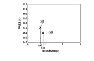
- FIG. 7 is a diagram in which the relationship between the energy saving operation time calculated in step S13 and the average room temperature acquired in step S14 (that is, the average room temperature when the energy saving operation is released) is visualized as a plane scatter diagram.
- the average room temperature is the vertical axis and the energy saving operation time is the horizontal axis.
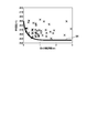
- FIG. 8 is a diagram in which the relationship between the energy saving operation time and the average room temperature obtained by executing the processing of steps S12 to S14 for each energy saving operation is visualized as a plane scatter diagram.
- each of the X marks in FIG. 8 feels uncomfortable for the occupant after the energy-saving operation is started. It shows the relationship between the time until (energy-saving operation is canceled) and the average room temperature at that time. In other words, FIG. 8 shows that how much room temperature has passed since the start of energy-saving operation and what room temperature would be uncomfortable for the occupants. I can say that.
- the energy-saving operation is released early when the room temperature is high after the energy-saving operation is started (that is, the occupant feels uncomfortable early).
- the energy-saving operation is not easily released (that is, the occupant is less likely to feel uncomfortable even in the energy-saving operation).
- the shorter the energy saving operation time and the lower the average room temperature the lower the discomfort of the occupants (the probability that the occupants can cancel the energy saving operation).
- the longer the energy saving operation time (the time has elapsed since the energy saving operation started) and the higher the average room temperature the higher the discomfort of the occupants.
- a relationship between an energy saving operation time (that is, an elapsed time since the energy saving operation is started) and an average room temperature when the energy saving operation is canceled is defined.
- a discomfort probability model shall be constructed.
- the model construction unit 13 determines the discomfort level of the occupants in the relationship (coordinates in the plane scatter diagram) between each energy saving operation time and the average room temperature when the energy saving operation is canceled as shown in FIG.
- a threshold line for estimating is generated (step S15).
- the threshold line generated in step S15 is, for example, a curve obtained by classifying a state where the occupant feels uncomfortable and a state where the occupant feels uncomfortable.
- a classification method for generating the threshold line for example, a method such as a 1-class support vector machine can be used, but other classification methods may be used.
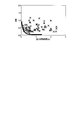
- FIG. 9 is a diagram showing the threshold lines generated in step S15 on the plane scatter diagram shown in FIG. According to the threshold line 301 shown in FIG. 9, it is estimated that the discomfort level of the occupant is low in the region below the threshold line 301 (energy saving operation time and average room temperature), and the region above the threshold line 301. In (energy saving operation time and average room temperature), the occupant's discomfort is estimated to be high.
- the model construction unit 13 uses such a threshold line, the above-described energy saving operation time, the average room temperature when the energy saving operation is canceled, and the discomfort corresponding to the energy saving operation time and the average room temperature (energy saving operation is canceled).
- a discomfort probability model in which the relationship with the probability is defined (step S16).
- the discomfort probability model constructed in step S16 is a 3D model in which discomfort is added to the relationship between the energy saving operation time described in FIGS. 7 to 9 and the average room temperature when the energy saving operation is canceled.
- this discomfort probability model with the above threshold line as a boundary, for example, the shorter the energy saving operation time and the lower the average room temperature, the lower the discomfort level is output, the longer the energy saving operation time and the higher the average room temperature. It is specified that a higher degree of discomfort is output.
- the discomfort probability model generated in step S16 is stored (registered) in the model storage unit 14 (step S17).
- the above-described model construction process (the process shown in FIG. 6) may be executed when, for example, a predetermined number of log data is stored in the log data storage unit 12, or the energy saving operation is canceled, for example. It may be executed when log data (for example, log data 123 and 125 shown in FIG. 4) that can be determined is stored in the log data storage unit 12.
- log data for example, log data 123 and 125 shown in FIG. 4
- log data acquired from other rooms (spaces) or buildings, etc. May be prepared in advance, and a discomfort probability model may be constructed based on the log data.
- the model building process is executed for each operation mode of the air conditioner. That is, in the present embodiment, a discomfort probability model for the cooling mode is constructed based on the log data acquired when the air conditioners 30A and 30B are operating in the cooling mode, and the air conditioners 30A and 30B are heated. A discomfort probability model for the heating mode is constructed based on the log data acquired when operating in the mode.
- the model construction process is described as being executed in the air conditioning control device 10, but the model construction processing may be executed outside the air conditioning control device 10. In this case, the discomfort probability model constructed by the model construction process executed outside the air conditioning control device 10 only needs to be stored in the model storage unit 14.
- the discomfort probability model stored in the model storage unit 14 may be updated based on the log data newly stored in the log data storage unit 12 after the discomfort probability model is constructed.
- the process shown in FIG. 10 is executed by the discomfort degree estimation unit 15 and the operation control unit 16 included in the air conditioning control device 10.
- the model storage unit 14 stores a discomfort probability model constructed by executing the model construction process described above.
- the discomfort degree estimation unit 15 refers to the log data stored in the log data storage unit 12 to determine whether the air conditioner 30A or the air conditioner 30B is in an energy saving operation (step S21).
- step S21 when the first energy saving operation flag included in the latest log data among the log data stored in the log data storage unit 12 is “1”, the air conditioner 30A is in the energy saving operation.
- the second energy saving operation flag included in the latest log data is “1”
- step S21 will be specifically described with reference to FIG. 4.
- the latest log data includes time “10:55”. This is log data, and the first energy-saving operation flag included in the log data is “1”.
- the air conditioner 30A is in an energy saving operation. Since the second energy saving operation flag in this case is “0”, the air conditioner 30B is not in the energy saving operation.
- the latest log data is log data including the time “13:55”, and the second data included in the log data.
- the energy saving operation flag is “1”. In this case, it is determined that the air conditioner 30B is in an energy saving operation. In this case, since the first energy saving operation flag is “0”, the air conditioner 30A is not in the energy saving operation.
- the latest log data is log data including the time “11:25”, and the first and Both the second energy saving operation flags are “0”. In this case, it is determined that the air conditioners 30A and 30B are not in the energy saving operation.
- the latest log data is log data including the time “14:25”, and the first log data included in the log data
- the second energy saving operation flag is both “0”. In this case, it is determined that the air conditioners 30A and 30B are not in the energy saving operation.
- step S21 When it is determined in step S21 that the air conditioner 30A or 30B is in the energy saving operation (YES in step S11), the discomfort degree estimation unit 15 receives the latest log data (hereinafter referred to as the first log) from the log data storage unit 12. Log data in which the energy saving operation flag (first or second energy saving operation flag) is changed from “0” to “1” (hereinafter referred to as second log data) is acquired (step S22).
- the energy saving operation flag first or second energy saving operation flag
- the time included in the first log data corresponds to the current time.
- the time included in the second log data corresponds to the time when the energy saving operation is started (energy saving operation start time).
- the discomfort degree estimation part 15 is based on the time contained in the 1st log data, and the time contained in the 2nd log data, and the current energy saving operation time (the elapsed time from the start of the energy saving operation to the present) Is calculated (step S23).
- the discomfort level estimation unit 15 estimates the discomfort level of the occupants in the room 20 using the discomfort probability model stored in the model storage unit 14 (step S24).
- the discomfort degree estimation unit 15 acquires the average room temperature (that is, the current average room temperature) included in the first log data as the current air conditioning state of the room 20, and the energy saving operation time calculated in step S23;
- the acquired average room temperature is applied to the discomfort probability model.
- the discomfort degree defined in the discomfort probability model is output in association with the relationship between the current energy saving operation time and the average room temperature.
- step S24 as described above, as the energy saving operation time is shorter and the average room temperature is lower, the lower discomfort is estimated (output), and as the energy saving operation time is longer and the average room temperature is higher, it is higher. The degree of discomfort is estimated (output).
- the discomfort probability model used here is a discomfort probability model (cooling discomfort probability model or heating discomfort probability model) corresponding to the operation mode of the air conditioners 30A and 30B.
- the discomfort degree estimation unit 15 determines whether or not the discomfort degree thus estimated is equal to or greater than a predetermined value (hereinafter referred to as a threshold value) (step S25).
- the operation control unit 16 executes a process for canceling the energy saving operation.
- the operation control unit 16 determines the set temperature (the set value of the air conditioning setting) after canceling the energy-saving operation (step S26).
- the set temperature determined in step S26 can be set to a set temperature immediately before the energy saving operation is started, for example.
- the set temperature immediately before the energy saving operation is started can be acquired from the set temperature (first or second set temperature) of the air conditioner during the energy saving operation included in the log data immediately before the second log data.
- the set temperature determined in step S26 may be a temperature that is changed in a direction in which the current set temperature is increased by a predetermined value, for example, a temperature that is predetermined by a building administrator or the like. Also good.
- the operation control unit 16 changes the set temperature of the air conditioner (air conditioner 30A or 30B) during the energy saving operation to the set temperature determined in step S16 (step S27). For example, when both the air conditioners 30A and 30B are in an energy saving operation, the set temperatures of the air conditioners 30A and 30B may be changed to the same set temperature (predetermined set temperature), respectively. It may be changed to a different set temperature (set temperature before the energy saving operation of each of the air conditioners 30A and 30B is started).
- step S27 When the process of step S27 is executed, the operation control unit 16 outputs a control signal indicating the set temperature (release of energy saving operation) determined in step S26 to the air conditioner during energy saving operation. According to this, the energy saving operation of the air conditioner during the energy saving operation is canceled, and the operation at the set temperature changed in step S27 is started.
- step S21 when it is determined in step S21 that the air conditioners 30A and 30B are not in the energy saving operation (NO in step S21), the processing in FIG. Similarly, when it is determined in step S25 that the degree of discomfort is not equal to or greater than the threshold value (less than the threshold value) (NO in step S25), the processing in FIG.
- the above-described discomfort level estimation process (the process shown in FIG. 10) is executed periodically, for example.
- the discomfort degree estimation process can be executed, for example, every time new log data is acquired (stored) (that is, at intervals of 5 minutes), but from the interval at which the log data is acquired. May be executed at long intervals (for example, at intervals of 10 minutes or 30 minutes).
- the air conditioning state for example, average room temperature
- the acquired air conditioning state and the air conditioner 30A or 30B The energy saving operation is canceled by applying the elapsed time from the start of the energy saving operation to the present time (that is, the current energy saving operation time) to the discomfort probability model.
- the discomfort probability model it is possible to estimate the discomfort level of the occupants in the room 20 based on the current air conditioning state and the energy saving operation time, and such discomfort level is equal to or greater than a threshold value. In this case, energy-saving operation is canceled.
- the setting of the air conditioner 30A or 30B during the energy saving operation is changed to the setting before the energy saving operation is started.
- the occupant cancels the energy-saving operation of the air conditioner 30A or 30B during the energy-saving operation by operating the remote controller 40A or 40B. (In other words, there is a possibility that the air-conditioning setting is changed in a direction to be strengthened).
- the air-conditioning setting may be further strengthened when the process for canceling the energy-saving operation is further executed. In this case, not only may there be a possibility of impairing the comfort of the occupants, but it will also be contrary to energy saving.
- the air conditioner 30A when the occupant performs a release operation during the energy saving operation of the air conditioner 30A, the air conditioner 30A is in the energy saving operation by the log data acquisition process described above.
- the log data including the first energy saving operation flag “0” indicating that it is not is stored in the log data storage unit 12.
- step S21 of the discomfort degree estimation process shown in FIG. 10 since it is determined that the air conditioner 30A is not in the energy saving operation, the processes after step S22 are not executed.
- the air-conditioning control device 10 cancels the energy-saving operation. Since no further setting change is performed, it is possible to avoid impairing the comfort of the occupants described above and improve energy saving performance.
- the case where the air conditioner 30A is in the energy saving operation has been mainly described, but the same applies to the case where the air conditioner 30B is in the energy saving operation.
- log data storage unit 12 stores log data including the date and time when energy-saving operation was started in the past, the date and time when the energy-saving operation was canceled by the occupant, and the past air conditioning state of room 20.
- a discomfort probability model can be constructed based on the log data.
- This discomfort probability model may be constructed (generated) outside the air conditioning control device 10 and stored in advance in the model storage unit 14 of the air conditioning control device 10, for example.
- the operation modes of the air conditioners 30A and 30B include a cooling mode and a heating mode.
- the air conditioners 30A and 30B are operating in the cooling mode, the occupant's discomfort level is estimated.
- a discomfort probability model constructed based on log data acquired during operation in the cooling mode is used.
- the discomfort constructed based on the log data acquired during the operation in the heating mode is used.
- a probabilistic model is used. That is, in this embodiment, the discomfort degree of the occupant can be estimated using different discomfort probability models according to the operation modes of the air conditioners 30A and 30B.
- the discomfort probability model is simply defined as a relationship between the energy-saving operation time and the average room temperature. It may be a model. According to such a discomfort probability model, for example, the position (coordinates) on the plane scatter diagram determined by the relationship between the current energy-saving operation time and the average room temperature indicates that the occupants classified by the threshold lines are uncomfortable. It can be set as the structure which cancel
- FIG. 11 is the figure which visualized the relationship between each energy saving operation time and a dispersion
- a discomfort probability model is constructed based on the dispersion value of the past temperature (room temperature) of the room 20, and the dispersion value of the temperature of the room 20 acquired as the current air conditioning state of the room 20 is calculated with respect to the discomfort probability model.
- the dispersion value is used instead of the average room temperature
- the maximum value or the minimum value among the room temperatures measured by a plurality of room temperature meters can be used. It is also possible to construct a multivariate model by combining some of average room temperature, dispersion, maximum value and minimum value of room temperature.
- a room temperature meter automatically arranged at a position capable of measuring a room temperature easily associated with a high degree of discomfort among a plurality of room temperature meters arranged in the room 20 is automatically used. It is also possible to select and use only the room temperature measured by the selected room temperature meter. According to such a configuration, for example, it is possible to cope with a case where there are a plurality of places where the effectiveness of air conditioning tends to deteriorate.
- the air conditioning control device 10 can be configured as shown in FIG. In FIG. 12, the same reference numerals are assigned to the same parts as those in FIG.
- the air conditioning control device 10 further includes, for example, a weather log storage unit 17a, a distribution board log storage unit 17b, and a resident log storage unit 17c.
- the weather log storage unit 17a stores a weather log reflecting the outside air load of the air conditioners 30A and 30B.
- the weather log includes, for example, outside air temperature, solar radiation, wind speed, and precipitation.
- the weather log may be measured by using various sensors, for example, or acquired (collected) from an external server device or the like. May be.
- the distribution board log storage unit 17b stores distribution board logs (hereinafter referred to as distribution board logs) that reflect the heat generated by various devices (hereinafter referred to as indoor apparatuses) arranged in the room 20. Has been.
- the distribution board log includes the operation amount of the indoor device that can be acquired from the distribution board. According to such a distribution board log, heat generation or the like in the indoor device can be obtained.
- the occupancy log storage unit 17c stores a log of the number of occupants in the room 20 that reflects the heat generated by the occupants in the room 20 (hereinafter referred to as occupancy log).
- the occupancy log (the number of occupants) may be acquired using, for example, a time card system related to the occupants in the room 20, an infrared sensor disposed in the room 20, or the like. It may be acquired by analyzing an image of a camera.
- the air conditioning control device 10 may include at least one of the weather log storage unit 17a, the distribution board log storage unit 17b, and the occupant log storage unit 17c illustrated in FIG.
- the weather log, distribution board log, and attendance log described above may be used in place of the room temperature described in the present embodiment, or may be used in combination with the room temperature.
- the weather log, the distribution board log, and the occupant log have been described as data other than room temperature.
- the data other than room temperature may be data such as humidity and carbon dioxide concentration in the room 20, for example.
- the humidity and the carbon dioxide concentration in the room 20 may be measured by a hygrometer and a carbon dioxide concentration meter disposed in the room 20 in the same manner as the room temperature meters 50A and 50B.
- the log data has been described as including the first and second energy saving operation flags.
- the first and second energy saving operation flags may not be included in the log data.
- the energy saving operation start time and the energy saving operation release time in step S12 shown in FIG. 6 may be specified based on changes in the first and second set temperatures included in the log data. The same applies to the determination processing of whether or not the air conditioners 30A and 30B in step S21 shown in FIG.
- the log data may be configured so that the average room temperature is not included.
- the average room temperature of the first and second room temperatures included in the log data may be calculated every time the process of step S14 shown in FIG.
- Air conditioners include indoor units installed indoors and outdoor units installed outdoors. In general air conditioners, about 90% of the required power is consumed by outdoor units. For this reason, when an upper limit is provided in power consumption as described above, it is necessary to control (change) the operation of the outdoor unit.
- an air conditioner capable of controlling a plurality of indoor units with one refrigerant system.
- the system often spans a plurality of rooms.
- indoor units 30A and 30B are installed in the indoor 20A
- an indoor unit 30C is installed in the indoor 20B
- the outdoor unit 70 installed in the outdoor 60 is like this. Heat is distributed to the indoor units 30A to 30C via the refrigerant pipe.
- the operation of the indoor units 30A to 30C is controlled according to the required amount from each of the indoor units 30A to 30C according to the set temperature and room temperature.
- the required amount from each of the indoor units 30A to 30C includes concepts such as the amount of electric power or the amount of heat necessary for air conditioning in each of the indoor units 30A to 30C.
- the indoor units 30A to 30C can be operated (operated) as required by the indoor units 30A to 30C.
- the total required amount total amount of power consumption required to operate the indoor units 30A to 30C as required by the indoor units 30A to 30C
- the ratio of the upper limit value of the power consumption is R
- the value obtained by multiplying each of the requested amounts from the indoor units 30A to 30C by R is the actual consumption amount (actual consumption amount) of the indoor unit.
- the whole air conditioner can be operated within the range of the upper limit value of power consumption.
- the building administrator may be able to specify (set) the actual consumption for each indoor unit, but the demand varies from moment to moment, so an upper limit is set for power consumption for the entire air conditioner. It is difficult for the building manager to specify the actual consumption amount for each air conditioner in real time.
- the air conditioner In the control of the air conditioner based on the upper limit value of the power consumption described above, heat is consumed regardless of the discomfort level of each of the rooms 20A and 20B.
- the indoor air conditioning capacity actual consumption of indoor units installed in a room with high discomfort
- the upper limit value of power consumption must be canceled (that is, the energy-saving operation of each of the indoor units 30A to 30C is canceled). Even though the operation can be continued, the energy-saving operation is canceled, resulting in an opportunity loss.
- the actual consumption of the indoor units 30A to 30C is controlled according to the degree of discomfort of the occupants in each of the rooms 20A and 20B.
- the degree is kept within a predetermined range, and energy saving operation (operation within the upper limit value of power consumption) is continued for a longer time.
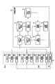
- FIG. 14 shows an example of the configuration of an air conditioning system including an air conditioning control device according to the present embodiment. Note that portions similar to those in FIG. 1 described above are denoted by the same reference numerals, and detailed description thereof is omitted. Here, parts different from FIG. 1 will be mainly described.
- the hardware configuration of the air-conditioning control apparatus 10 according to the present embodiment is the same as that of the first embodiment described above, and will be described with reference to FIG. 2 as appropriate.
- the indoor units 30A and 30B are installed in the indoor 20A, and the indoor unit 30C is installed in the indoor 20B.
- the outdoor unit 70 installed in the outdoor 60 is connected via a refrigerant pipe so as to distribute heat to the indoor units 30A to 30C.
- indoor units 30A and 30B correspond to the air conditioners 30A and 30B in the first embodiment described above.
- the indoor unit 30C, the remote controller 40C, and the room temperature meter 50C are the same as the indoor unit 30A, the remote controller 40A, the room temperature meter 50A, and the like except that the installed (arranged) location is the room 20B. Description is omitted.
- the air conditioning control device 10 includes an installation data storage unit 18 and an upper limit setting unit 19.
- the installation data storage unit 18 stores in advance data indicating the location (indoor) where each indoor unit is installed (hereinafter referred to as installation data).
- the upper limit setting unit 19 sets an upper limit of power consumption of the entire air conditioner (hereinafter referred to as a power upper limit value).
- the power upper limit value may be specified by, for example, a building manager or the like, or a predetermined value may be automatically set at a predetermined time.
- the operation control unit 16 in the present embodiment based on the estimation result of the discomfort level for each of the indoors 20A and 20B by the discomfort level estimation unit 15, the actual consumption amount of each of the indoor units 30A to 30C. It has a function to control.
- FIG. 15 shows an example of the data structure of the installation data stored in the installation data storage unit 18 shown in FIG.
- the installation data includes an indoor ID and an indoor unit ID.
- the room ID is an identifier for identifying the room in which the indoor unit is installed.
- the indoor unit ID is an identifier for identifying an indoor unit installed in a room identified by the indoor ID associated with the indoor unit ID.
- the installation data storage unit 18 stores a plurality of installation data including installation data 181 to 183.
- the installation data 181 includes an indoor ID “20A” and an indoor unit ID “30A”. According to the installation data 181, the indoor unit identified by the indoor unit ID “30A” (here, the indoor unit 30A) is installed in the room identified by the indoor ID “20A” (here, the room 20A). It has been shown that
- the installation data 182 includes an indoor ID “20A” and an indoor unit ID “30B”. According to the installation data 182, the indoor unit identified by the indoor unit ID “30B” (here, the indoor unit 30B) is installed in the room identified by the indoor ID “20A” (here, the room 20A). It has been shown that
- the installation data 183 includes an indoor ID “20B” and an indoor unit ID “30C”. According to the installation data 183, the indoor unit (here, the indoor unit 30C) identified by the indoor unit ID “30C” is installed in the room (here, the room 20B) identified by the room ID “20B”. It has been shown that
- FIG. 16 shows an example of the data structure of log data stored in the log data storage unit 12 in the present embodiment.
- the first set temperature, the first room temperature, the first energy saving operation flag, the first required amount, the second set temperature, the second room temperature, and the second energy saving operation are associated with the time.
- the flag, the second required amount, the third set temperature, the third room temperature, the third energy saving operation flag, and the third required amount are included.
- the first set temperature, the first room temperature, the first energy saving operation flag, the second set temperature, the second room temperature, and the second energy saving operation flag are the same as those in the first embodiment, Detailed description is omitted.
- the first requested amount indicates the requested amount from the indoor unit 30A.
- the second request amount indicates the request amount from the indoor unit 30B.
- the third set temperature is the set temperature of the indoor unit 30C.
- the third room temperature is the room temperature of the room 20B measured by the room temperature meter 50C.
- the third energy saving operation flag indicates whether the indoor unit 30C is in an energy saving operation. When the third energy saving operation flag is “0”, it indicates that the indoor unit 30C is not in energy saving operation, and when the third energy saving operation flag is “1”, the indoor unit 30C is in energy saving operation. Indicates.
- the third request amount indicates the request amount from the indoor unit 30C.
- the log data includes the requested amount from each of the indoor units 30A to 30C at the time included in the log data.
- the air conditioning control apparatus 10 executes each of log data acquisition processing and model construction processing, as in the first embodiment described above.
- the requested amount included in the log data is acquired from each of the indoor units 30A to 30C (that is, the log data including the requested amount is stored in the log data storage unit 12). Except for this point, the second embodiment is the same as the first embodiment described above, and a detailed description thereof will be omitted.
- the model construction process in this embodiment is executed for each of the rooms 20A and 20B (that is, rooms).
- the log data stored in the log data storage unit 12 is divided into log data relating to the rooms 20A and 20B, and each of the log data relating to the rooms 20A and 20B.
- the above-described processing shown in FIG. 6 is executed.
- the discomfort probability model is constructed for each of the rooms 20A and 20B.
- the log data related to the room 20A includes the time, the first set temperature (the set temperature of the indoor unit 30A), the first room temperature (the room temperature measured by the room temperature meter 50A), the first shown in FIG. Energy saving operation flag (flag indicating whether indoor unit 30A is in energy saving operation), second set temperature (set temperature of indoor unit 30B), second room temperature (room temperature measured by room temperature meter 50B) and second
- the log data related to the room 20B includes the time, the third set temperature (the set temperature of the indoor unit 30C), the third room temperature (the room temperature measured by the room temperature meter 50C), and the third shown in FIG.
- This is log data including an energy saving operation flag (a flag indicating whether the indoor unit 30C is in an energy saving operation).
- the process shown in FIG. 6 is executed based on the log data related to the room 20B, for example, the third room temperature is acquired in step S14.
- the log data relating to the indoors 20A and 20B described above can be obtained by specifying the indoor units installed in the indoors 20A and 20B based on the installation data stored in the installation data storage unit 18, thereby providing a log data storage unit. 12 can be obtained.
- the process of controlling the actual consumption of the indoor units 30A to 30C in accordance with the discomfort level of the occupants in each room 20A and 20B (hereinafter referred to as the actual consumption control process). (Notation).
- the discomfort degree estimation unit 15 determines whether or not the power upper limit (unit: W) is set by the upper limit setting unit 19 (step S31).
- the discomfort level estimation unit 15 executes a discomfort level estimation process (step S32).
- the discomfort degree estimation process in step S32 the above-described processes in steps S21 to S25 shown in FIG. 10 are executed for each of the rooms 20A and 20B. According to this, in step S32, it is possible to identify a room having a discomfort level equal to or greater than the threshold value among the rooms 20A and 20B.
- the room where the discomfort degree is equal to or greater than the threshold is the room 20A
- the room 20B is assumed that the discomfort degree is not above the threshold.
- at least one of the indoor units (in this case, the indoor units 30A and 30B) installed in the indoor 20A is in an energy saving operation.
- the energy saving operation in the present embodiment refers to a state in which an operation is performed with an actual consumption amount smaller than a required amount from the air conditioner.
- the operation control unit 16 refers to the installation data storage unit 18 and identifies a set of indoor units installed in a room whose discomfort level is equal to or greater than a threshold value (hereinafter referred to as an indoor unit set) (step). S33). As described above, assuming that the room with the discomfort degree equal to or greater than the threshold is the room 20A, the indoor units 30A and 30B are specified as the indoor unit set in step S33.
- the operation control unit 16 requests each of the indoor units 30A and 30B (first and second request amounts) included in the latest log data among the log data stored in the log data storage unit 12. Is acquired (step S34).
- the request amount acquired in step S34 corresponds to the current request amounts of the indoor units 30A and 30B.
- step S34 When the process of step S34 is executed, the operation control unit 16 calculates E by the following formula (1) (step S35).
- Equation (1) L is the upper limit value of electric power, U is an indoor unit set, and k is an indoor unit (number) belonging to the indoor unit set. In addition, Sk indicates a required amount (unit: W) of the indoor unit k.
- E calculated in step S35 is necessary for operating each of the indoor units k (in this case, the indoor units 30A and 30B) belonging to the indoor unit set U from the above power upper limit value L as required. It is a value obtained by subtracting the total amount of power consumption. In other words, E can consume the indoor unit 30C installed in the room 20B having a low degree of discomfort when the indoor units 30A and 30B installed in the room 20A having a high level of discomfort are operated as required. It shows the amount of power.
- step S35 determines whether or not E calculated in step S35 is a value larger than 0 (that is, E> 0) (step S36).
- the operation control unit 16 calculates the actual consumption amount (unit) of each of the indoor units 30A to 30C according to the following formulas (2) and (3). : W) is determined (step S37).
- the actual consumption amount Sk ′ of each indoor unit k belonging to the indoor unit set U specified in step S33 is the required amount Sk of each indoor unit k. That is, the actual consumption amount of the indoor unit 30A installed in the indoor 20A having a high degree of discomfort is the required amount of the indoor unit 30A, and the actual consumption amount of the indoor unit 30B is the required amount of the indoor unit 30B. In this case, each of the indoor units 30A and 30B can be operated with an actual consumption amount as required.
- the actual consumption amount Sk ′ of each indoor unit k that does not belong to the indoor unit set U specified in step S33 is equal to E calculated in step S35.
- the value is prorated by the amount Sk.
- the indoor unit 30C is the only indoor unit that does not belong to the set of indoor units (that is, the indoor unit installed in the room 20B having a low degree of discomfort)
- the actual consumption amount of the indoor unit 30C is the same value as E. It becomes.
- indoor units k1 and k2 when there are two indoor units that do not belong to the indoor unit set U (hereinafter referred to as indoor units k1 and k2), and the required amounts of the two indoor units k1 and k2 are Sk1 and Sk2, respectively.
- the actual consumption amount Sk1 ′ of the indoor unit k1 whose request amount is Sk1 is E * Sk1 / (Sk1 + Sk2).
- the actual consumption amount Sk2 ′ of the indoor unit k2 whose required amount is Sk2 is E * Sk2 / (Sk1 + Sk2).
- the actual consumption amount of the indoor unit 30C not belonging to the set of indoor units determined in step S37 is larger than the required amount of the indoor unit 30C
- the actual consumption amount of the indoor unit 30C is the required amount of the indoor unit 30C. It is good also as the same value.
- the operation control unit 16 transmits the actual consumption amount of each of the indoor units 30A to 30C determined in the step S37 as a control signal to the outdoor unit 70 (step S38).
- the outdoor unit 70 operates so as to operate each of the indoor units 30A to 30C based on the actual consumption amount of each of the indoor units 30A to 30C transmitted from the air conditioning control device 10 (operation control unit 16). To do.
- step S36 when it is determined in step S36 that E is not a value greater than 0 (NO in step S36), each of the indoor units 30A to 30C cannot be operated within the range of the power upper limit value. Then, the power upper limit value is canceled (step S39).
- step S31 If it is determined in step S31 that the power upper limit value is not set (NO in step S31), the actual consumption control process shown in FIG. 17 is terminated.
- the actual consumption control process described above is executed periodically, for example.
- the actual consumption control process can be executed, for example, every time new log data is acquired (stored) (that is, at intervals of 5 minutes), but the interval at which the log data is acquired. It may be executed at a longer interval (for example, an interval of 10 minutes or an interval of 30 minutes).
- the actual consumption control process is described as being terminated when the power upper limit value is not set.
- the above-described FIG. Processing may be executed.
- the energy-saving operation of the indoor units 30A to 30C installed in the indoors 20A and 20B can be canceled according to the discomfort level of the occupants in the indoors 20A and 20B.
- the discomfort probability model is constructed for each of the rooms 20A and 20B (that is, rooms), and therefore the process shown in FIG. 10 is executed for each of the rooms 20A and 20B.
- the discomfort level of the occupants in the rooms 20A and 20B is estimated, and the presence of the room 20A is estimated.
- the indoor units 30A and 30B first air conditioners
- the indoor units 30A and 30B are released from the energy-saving operation to be normally operated, and the room installed in the room 20B.
- the amount of power necessary for normal operation of the indoor units 30A and 30B is subtracted from the power upper limit value (the upper limit of power consumption in the indoor units 30A to 30C and the outdoor unit 70).
- the normal operation of the indoor unit means that the indoor unit is operated as requested from the indoor unit (that is, the requested amount from the indoor unit is operated as an actual consumption amount).
- the indoor units 30A and 30B installed in the room 20A having a high degree of discomfort are normally operated as required in order to eliminate the unpleasant state, and the room having a low degree of discomfort Since the indoor unit 30C installed in 20B can be operated in an energy-saving manner within the limit of the power upper limit value, it becomes possible to achieve both comfort and energy-saving performance of the occupants in each room 20A and 20B.
- the actual consumption of each of the indoor units 30A to 30B is controlled (restricted) via the outdoor unit 70.
- each indoor unit is directly connected without passing through the outdoor unit 70. It may be configured to control the actual consumption of 30A to 30C.
- the present embodiment may be configured in combination with the first embodiment described above.
- the air conditioning control device 10 according to the present embodiment has a weather log storage unit 17a, a distribution board log storage unit 17b, and a distribution board log storage unit 17b illustrated in FIG.
- a resident log storage unit 17c or the like may be provided.
- the air-conditioning control device when the air conditioner is in an energy-saving operation, the air-conditioning control device, the air-conditioning system, and the air-conditioner that can cancel the energy-saving operation before the occupant feels uncomfortable
- a control method and a program can be provided.
Abstract
The air-conditioning control device according to an embodiment of the present invention is provided with a model storage means, an acquisition means, and a control means. The model storage means stores a discomfort probability model in which an estimate of the degree of discomfort perceived by a person in a room with respect to the relation between a period until an energy-saving operation of an air conditioner installed in the room is canceled by the person in the room after initiation of the energy-saving operation, and an air-conditioning state in the room at the time when the energy-saving operation is cancelled. The acquisition means acquires the current air-conditioning state in the room during the energy-saving operation of the air conditioner. The control means cancels the energy-saving operation on the basis of the degree of discomfort perceived by a person in the room, the degree of discomfort being obtained by applying the acquired air-conditioning state and the elapsed time of the energy-saving operation to the discomfort probability model.
Description
本発明の実施形態は、空調制御装置、空調システム、空調制御方法及びプログラムに関する。
Embodiments described herein relate generally to an air conditioning control device, an air conditioning system, an air conditioning control method, and a program.
一般的に、オフィス等の室内には空調機が設置されているが、この空調機においては省エネルギー化を実現するような運転(以下、空調機の省エネ運転と表記)が求められている。
Generally, an air conditioner is installed in a room such as an office. However, this air conditioner is required to be operated so as to save energy (hereinafter referred to as an energy saving operation of the air conditioner).
空調機の省エネ運転は、例えば消費電力に上限を設ける(セーブ運転)、または空調機の設定温度や風量を緩和すること等によって行われる。また、複数の空調機が設置されている場合には、当該複数の空調機の出力タイミングをずらすこと(ピークシフト)等によっても省エネルギー化を実現することができる。
The energy-saving operation of the air conditioner is performed, for example, by setting an upper limit for power consumption (save operation) or by relaxing the set temperature and air volume of the air conditioner. Further, when a plurality of air conditioners are installed, energy saving can also be realized by shifting the output timing of the plurality of air conditioners (peak shift) or the like.
省エネルギー化の観点によれば、空調機の省エネ運転は、空調機が設置されている室内の快適性が維持される限り長時間継続されることが望ましい。
From the viewpoint of energy saving, it is desirable that the energy saving operation of the air conditioner is continued for a long time as long as the comfort of the room where the air conditioner is installed is maintained.
しかしながら、空調機の省エネ運転においては、通常必要とされる電力よりも少ない電力で空調機を運転するため、室内の快適性は徐々に低下する。
However, in the energy-saving operation of an air conditioner, the air conditioner is operated with less power than is normally required, so the indoor comfort gradually decreases.
室内の快適性が徐々に低下し、当該室内にいる者(以下、在室者と表記)が不快と感じた場合には、当該在室者は例えばリモコン等を操作することによって空調機の省エネ運転を解除(停止)することができるが、当該省エネ運転を解除する操作を行うことは煩雑である。
When the comfort in the room gradually decreases and the person in the room (hereinafter referred to as occupant) feels uncomfortable, the occupant can save energy of the air conditioner by operating, for example, a remote controller. Although the operation can be canceled (stopped), it is complicated to perform an operation for canceling the energy saving operation.
このため、空調機の省エネ運転の開始後、在室者が不快と感じるまでの間に当該省エネ運転を自動的に解除することが考えられる。
Therefore, it is conceivable that the energy-saving operation is automatically canceled after the start of the energy-saving operation of the air conditioner until the occupant feels uncomfortable.
しかしながら、在室者が不快と感じるまでの時間は、例えば空調機が設置されている環境に応じて例えば10分程度から数時間のように幅があるため、事前に把握することは困難である。
However, since the time until the occupant feels uncomfortable varies, for example, from about 10 minutes to several hours depending on the environment where the air conditioner is installed, it is difficult to grasp in advance. .
そこで、本発明が解決しようとする課題は、空調機の省エネ運転の開始後、在室者が不快に感じる前に当該省エネ運転を解除することが可能な空調制御装置、空調システム、空調制御方法及びプログラムを提供することにある。
Therefore, the problem to be solved by the present invention is that an air conditioning control device, an air conditioning system, and an air conditioning control method capable of releasing the energy saving operation before the occupant feels uncomfortable after starting the energy saving operation of the air conditioner And providing a program.
実施形態に係る空調制御装置は、モデル格納手段と、取得手段と、制御手段とを具備する。前記モデル格納手段は、室内に設置された空調機の省エネ運転が開始された後、在室者によって当該省エネ運転が解除されるまでの時間と、当該省エネ運転が解除された際の前記室内の空調状態との関係に対する在室者の不快度の推定値が定義された不快確率モデルを格納する。前記取得手段は、前記空調機の省エネ運転中に、前記室内の現在の空調状態を取得する。前記制御手段は、前記取得された空調状態と、前記省エネ運転が開始されてから現在までの経過時間とを前記不快確率モデルに適用することによって得られる在室者の不快度に基づいて、当該省エネ運転を解除する。
The air-conditioning control apparatus according to the embodiment includes model storage means, acquisition means, and control means. The model storage means includes a time until the energy-saving operation is canceled by a resident after the energy-saving operation of the air conditioner installed in the room is started, and the indoor space when the energy-saving operation is canceled. Stores a discomfort probability model in which an estimate of the discomfort level of the occupant for the relationship with the air conditioning state is defined. The acquisition means acquires the current air conditioning state in the room during the energy saving operation of the air conditioner. The control means, based on the degree of discomfort of the occupants obtained by applying the acquired air conditioning state and the elapsed time from the start of the energy-saving operation to the present to the discomfort probability model, Cancel energy-saving operation.
以下、図面を参照して、各実施形態について説明する。
(第1の実施形態)
図1は、第1の実施形態に係る空調制御装置を含む空調システムの構成の一例を示す。図1に示すように、空調システムは、空調制御装置10及び当該空調制御装置10と伝送路を介して接続される空調機を備える。 Hereinafter, each embodiment will be described with reference to the drawings.
(First embodiment)
FIG. 1 shows an example of the configuration of an air conditioning system including an air conditioning control device according to the first embodiment. As shown in FIG. 1, the air conditioning system includes an airconditioning control device 10 and an air conditioner connected to the air conditioning control device 10 via a transmission path.
(第1の実施形態)
図1は、第1の実施形態に係る空調制御装置を含む空調システムの構成の一例を示す。図1に示すように、空調システムは、空調制御装置10及び当該空調制御装置10と伝送路を介して接続される空調機を備える。 Hereinafter, each embodiment will be described with reference to the drawings.
(First embodiment)
FIG. 1 shows an example of the configuration of an air conditioning system including an air conditioning control device according to the first embodiment. As shown in FIG. 1, the air conditioning system includes an air
本実施形態において、空調機は、例えばビル内の部屋等の室内(空間)に設置され、当該室内の空調を行う室内機を含む。本実施形態においては、図1に示すように、空調システムが室内20に設置されている空調機30A及び30Bを備えるものとして説明するが、当該空調システムに備えられる空調機は、1つであってもよいし、3つ以上であってもよい。
In the present embodiment, the air conditioner includes an indoor unit that is installed in a room (space) such as a room in a building and performs air conditioning of the room. In the present embodiment, as shown in FIG. 1, the air conditioning system will be described as including air conditioners 30A and 30B installed in the room 20, but the air conditioning system includes one air conditioner. It may be three or more.
なお、室内20は、家屋またはビル等の施設全体であってもよいし、施設内の一区域であって、床及び内壁等で区別された空間であってもよい。
The room 20 may be the entire facility such as a house or a building, or may be a space in the facility that is distinguished by a floor, an inner wall, and the like.
空調機30Aは、例えば室内20にいる者(以下、在室者と表記)によってリモコン40Aを介して入力された空調設定の設定値に応じて室内20の空調を行う。空調機30Aには室内20の温度(室温)を計測する室温計50Aが接続されており、空調機30Aは、室温計50Aによって計測された室温に基づいて空調を行う。
The air conditioner 30A performs air conditioning of the room 20 according to the set value of the air conditioning setting input via the remote controller 40A by, for example, a person in the room 20 (hereinafter referred to as a resident). A room temperature meter 50A for measuring the temperature (room temperature) of the room 20 is connected to the air conditioner 30A. The air conditioner 30A performs air conditioning based on the room temperature measured by the room temperature meter 50A.
同様に、空調機30Bは、例えば在室者によってリモコン40Bを介して入力された空調設定の設定値に応じて室内20の空調を行う。空調機30Bには室温計50Bが接続されており、空調機30Bは、室温計50Bによって計測された室温に基づいて空調を行う。
Similarly, the air conditioner 30B performs air conditioning of the room 20 according to the set value of the air conditioning setting input by the occupant via the remote control 40B, for example. A room temperature meter 50B is connected to the air conditioner 30B, and the air conditioner 30B performs air conditioning based on the room temperature measured by the room temperature meter 50B.
上記した室温計50A及び50Bは、それぞれ空調機30A及び30Bに組み込まれていてもよいし、室内20の異なる位置に配置されていてもよい。更に、室温計50A及び50Bは、同一の室温計であっても構わない。
The above-described room temperature meters 50A and 50B may be incorporated in the air conditioners 30A and 30B, respectively, or may be arranged at different positions in the room 20. Furthermore, the room temperature meters 50A and 50B may be the same room temperature meter.
空調制御装置10は、空調機30A及び30Bの運転を制御する(つまり、室内20の空調を制御する)ための装置であり、例えばビルの管理室等に設けられている。空調制御装置10は、例えばビル管理者が室内20の空調状態を把握する、または各空調機30A及び30Bの設定を変更する目的で導入されるBEMS(Building Energy Management System)等の機器であってもよいし、空調システムにおいて使用される他の機器であってもよい。
The air conditioning control device 10 is a device for controlling the operation of the air conditioners 30A and 30B (that is, controlling the air conditioning of the room 20), and is provided in a management room of a building, for example. The air conditioning control device 10 is a device such as a BEMS (Building Energy Management System) that is introduced for the purpose of, for example, a building administrator grasping the air conditioning state of the room 20 or changing the settings of the air conditioners 30A and 30B. Alternatively, other equipment used in the air conditioning system may be used.
図1に示すように、空調制御装置10は、ログデータ取得部11、ログデータ格納部12、モデル構築部13、モデル格納部14、不快度推定部15及び運転制御部16を含む。
As shown in FIG. 1, the air conditioning control device 10 includes a log data acquisition unit 11, a log data storage unit 12, a model construction unit 13, a model storage unit 14, a discomfort degree estimation unit 15, and an operation control unit 16.
ログデータ取得部11は、空調機30A及び30Bの運転状況及び室内20の空調状態の履歴を含むログデータを、当該空調機30A及び30Bの各々から取得する。ログデータは、予め定められた間隔で取得され、ログデータ格納部12に格納される。すなわち、ログデータ格納部12には、空調機30A及び30Bの過去の運転状況及び室内20の過去の空調状態を含むログデータが蓄積されている。
The log data acquisition unit 11 acquires log data including the operation status of the air conditioners 30A and 30B and the history of the air condition of the room 20 from each of the air conditioners 30A and 30B. The log data is acquired at predetermined intervals and stored in the log data storage unit 12. In other words, the log data storage unit 12 stores log data including past operating conditions of the air conditioners 30A and 30B and past air conditioning conditions of the room 20.
ここで、本実施形態において、各空調機30A及び30Bは、省エネ運転が可能であるものとする。本実施形態における省エネ運転とは省エネルギー化を実現する(つまり、空調システムが少ないエネルギーで稼働する)ような空調機の運転であり、例えば空調設定が緩和された状態の空調機の運転を含む。なお、本実施形態において「空調設定が緩和される」とは、空調機の運転モードが冷房モードである場合には当該空調機の設定温度が上げられることを含み、空調機の運転モードが暖房モードである場合には当該空調機の設定温度が下げられることを含む。なお、「空調設定が緩和される」には、例えば空調機から出力される風量を低減することが含まれていてもよい。本実施形態において、省エネ運転以外の運転は便宜的に通常運転と称する。
Here, in this embodiment, it is assumed that each of the air conditioners 30A and 30B is capable of energy-saving operation. The energy saving operation in the present embodiment is an operation of an air conditioner that realizes energy saving (that is, the air conditioning system operates with less energy), and includes, for example, the operation of the air conditioner in a state where the air conditioning setting is relaxed. In the present embodiment, “the air conditioning setting is relaxed” means that when the operation mode of the air conditioner is the cooling mode, the set temperature of the air conditioner is raised, and the operation mode of the air conditioner is the heating mode. In the case of the mode, it includes that the set temperature of the air conditioner is lowered. Note that “releasing the air conditioning setting” may include, for example, reducing the air volume output from the air conditioner. In the present embodiment, the operation other than the energy saving operation is referred to as normal operation for convenience.
各空調機30A及び30Bの省エネ運転は、例えば在室者によるリモコン40A及び40Bに対する操作に応じて開始されてもよいし、予め定められた条件等に従って開始されてもよい。省エネ運転が開始される条件には、例えば予め定められた時間となったこと及び室内20が予め定められた温度になったこと等が含まれる。また、例えば各空調機30A及び30Bの運転モードが冷房モードである場合、当該空調機30A及び30Bの設定温度が在室者により上げられる傾向のある時間帯となった際に省エネ運転が開始されてもよい。同様に、各空調機30A及び30Bの運転モードが暖房モードである場合には、当該空調機30A及び30Bの設定温度が在室者により下げられる傾向のある時間帯となった際に省エネ運転が開始されてもよい。設定温度が上げられる傾向のある時間帯及び設定温度が下げられる傾向のある時間帯は、例えば上記したログデータ格納部12に格納されているログデータまたはその他のデータから特定されてもよい。
The energy saving operation of each of the air conditioners 30A and 30B may be started in accordance with, for example, an operation on the remote controls 40A and 40B by a resident, or may be started according to a predetermined condition or the like. The conditions for starting the energy saving operation include, for example, that a predetermined time has been reached and that the room 20 has reached a predetermined temperature. Further, for example, when the operation mode of each of the air conditioners 30A and 30B is the cooling mode, the energy saving operation is started when the set temperature of the air conditioners 30A and 30B is in a time zone that tends to be raised by the occupants. May be. Similarly, when the operation mode of each of the air conditioners 30A and 30B is the heating mode, the energy saving operation is performed when the set temperature of the air conditioners 30A and 30B tends to be lowered by the occupants. May be started. The time zone in which the set temperature tends to increase and the time zone in which the set temperature tends to decrease may be specified from, for example, log data stored in the log data storage unit 12 or other data.
なお、上記した省エネ運転においては、通常必要とされるよりも少ないエネルギー(電力)で空調機が運転されるため、省エネ運転が継続されると室内の快適性は徐々に低下し、結果として、在室者はいずれ不快と感じるようになる。
In the energy saving operation described above, the air conditioner is operated with less energy (electric power) than is normally required, so if the energy saving operation is continued, the indoor comfort gradually decreases, Residents will eventually feel uncomfortable.
モデル構築部13は、ログデータ格納部12に格納されたログデータに基づいて不快確率モデルを構築する。不快確率モデルは、上記した省エネ運転が開始されてからの経過時間と室内20の空調状態とに基づく当該室内20における在室者の不快度(室内20において在室者が不快と感じている度合い)を推定するために用いられるモデルである。モデル構築部13によって構築された不快確率モデルは、モデル格納部14に格納される。なお、不快確率モデルの詳細については後述する。
The model construction unit 13 constructs a discomfort probability model based on the log data stored in the log data storage unit 12. The discomfort probability model is the degree of discomfort of the occupants in the room 20 based on the elapsed time since the start of the energy-saving operation and the air conditioning state of the room 20 (the degree that the occupants feel uncomfortable in the room 20). ) Is a model used for estimating. The discomfort probability model constructed by the model construction unit 13 is stored in the model storage unit 14. Details of the discomfort probability model will be described later.
不快度推定部15は、上記した空調機30A及び30Bの省エネ運転中に、モデル格納部14に格納された不快確率モデルを用いて在室者の不快度を推定(評価)する。
The discomfort degree estimation unit 15 estimates (evaluates) the discomfort level of the occupants using the discomfort probability model stored in the model storage unit 14 during the energy saving operation of the air conditioners 30A and 30B.
運転制御部16は、不快度推定部15によって推定された不快度に基づいて、空調機30A及び30Bの省エネ運転を解除する。この場合、運転制御部16は、空調機30A及び30Bの空調設定(例えば、設定温度)を強める方向に変更する。
The operation control unit 16 cancels the energy-saving operation of the air conditioners 30A and 30B based on the discomfort level estimated by the discomfort level estimation unit 15. In this case, the operation control unit 16 changes the direction so as to increase the air conditioning settings (for example, set temperature) of the air conditioners 30A and 30B.
なお、本実施形態において「空調設定を強める」とは、上記した「空調設定が緩和される」の反対の意であり、例えば空調機の運転モードが冷房モードである場合には当該空調機の設定温度が下げられることを含み、空調機の運転モードが暖房モードである場合には当該空調機の設定温度が上げられることを含む。
In this embodiment, “increasing air conditioning settings” is the opposite of “relaxing air conditioning settings” described above. For example, when the operation mode of the air conditioner is the cooling mode, the air conditioner This includes that the set temperature is lowered, and that the set temperature of the air conditioner is raised when the operation mode of the air conditioner is the heating mode.
なお、ビル管理者は、空調制御装置10を操作することによって、ログデータ格納部12に格納されたログデータを空調制御装置10の表示装置に表示させることが可能である。また、ビル管理者は、上記したリモコン40A及び40Bと同様に空調制御装置10を操作することによって、空調機30A及び30Bの空調設定の設定値を変更するまたは省エネ運転を開始することも可能である。
In addition, the building administrator can display the log data stored in the log data storage unit 12 on the display device of the air conditioning control device 10 by operating the air conditioning control device 10. Further, the building manager can change the set value of the air conditioning setting of the air conditioners 30A and 30B or start the energy saving operation by operating the air conditioning control device 10 in the same manner as the remote controls 40A and 40B described above. is there.
図2は、本実施形態に係る空調制御装置10のハードウェア構成の一例を示す。図2に示すように、空調制御装置10は、CPU101、不揮発性メモリ102、主メモリ103及び通信デバイス104等を備える。
FIG. 2 shows an example of the hardware configuration of the air conditioning control device 10 according to the present embodiment. As shown in FIG. 2, the air conditioning control device 10 includes a CPU 101, a nonvolatile memory 102, a main memory 103, a communication device 104, and the like.
CPU101は、空調制御装置10内の様々なコンポーネントの動作を制御するハードウェアプロセッサである。CPU101は、ストレージデバイスである不揮発性メモリ102から主メモリ103にロードされる様々なプログラムを実行する。CPU101によって実行されるプログラムには、オペレーティングシステム及び空調機30A及び30Bの運転を制御するためのアプリケーションプログラム(以下、空調制御プログラムと表記)等が含まれる。なお、CPU101は、例えばハードウェア制御のためのプログラムである基本入出力システム(BIOS)等も実行する。
The CPU 101 is a hardware processor that controls the operation of various components in the air conditioning control device 10. The CPU 101 executes various programs loaded from the nonvolatile memory 102 that is a storage device to the main memory 103. The program executed by the CPU 101 includes an operating system and an application program (hereinafter referred to as an air conditioning control program) for controlling the operation of the air conditioners 30A and 30B. The CPU 101 also executes a basic input / output system (BIOS), which is a program for hardware control, for example.
なお、図2においては、空調制御装置10がCPU101を備えるものとして説明するが、空調制御装置10は、上記したプログラムを実行可能であれば、CPU101以外のプロセッサまたはコントローラ等を備えていてもよい。
In FIG. 2, the air conditioning control device 10 is described as including the CPU 101, but the air conditioning control device 10 may include a processor or controller other than the CPU 101 as long as the above-described program can be executed. .
本実施形態において、上記した図1に示すログデータ取得部11、モデル構築部13、不快度推定部15及び運転制御部16の一部または全ては、上記したCPU101に空調制御プログラムを実行させること、すなわち、ソフトウェアによって実現されるものとする。なお、これらの各部11、13、15及び16の一部または全ては、IC(Integrated Circuit)等のハードウェアによって実現されてもよいし、ソフトウェア及びハードウェアの組み合わせ構成として実現されてもよい。
In the present embodiment, some or all of the log data acquisition unit 11, the model construction unit 13, the discomfort degree estimation unit 15, and the operation control unit 16 illustrated in FIG. 1 cause the CPU 101 to execute an air conditioning control program. That is, it shall be realized by software. Part or all of these units 11, 13, 15 and 16 may be realized by hardware such as an IC (Integrated Circuit), or may be realized as a combination configuration of software and hardware.
また、本実施形態において、図1に示すログデータ格納部12及びモデル格納部14は、上記した不揮発性メモリ102等の記憶装置によって実現される。
In the present embodiment, the log data storage unit 12 and the model storage unit 14 illustrated in FIG. 1 are realized by a storage device such as the nonvolatile memory 102 described above.
通信デバイス104は、外部装置と例えば有線または無線による通信を実行するように構成されたデバイスである。
The communication device 104 is a device configured to execute, for example, wired or wireless communication with an external device.
図2においては、便宜的に空調制御装置10がCPU101、不揮発性メモリ102、主メモリ103及び通信デバイス104を備えるものとして説明したが、空調制御装置10は、上記したようにログデータを表示するための表示装置及び各空調機30A及び30Bの空調設定の設定値を変更するための入力装置等を更に備えていてもよい。
In FIG. 2, for the sake of convenience, the air conditioning control device 10 has been described as including the CPU 101, the nonvolatile memory 102, the main memory 103, and the communication device 104. However, the air conditioning control device 10 displays log data as described above. A display device and an input device for changing the setting values of the air conditioning settings of the air conditioners 30A and 30B may be further provided.
以下、図1に示すログデータ格納部12に格納されるログデータについて説明する。図3は、空調機30A及び30Bの運転モードが冷房モードである場合における、上記した省エネ運転と室内20の空調状態との関係性を示す。
具体的には、図3の上段は、空調機30Aの設定温度の推移を可視化して示している。なお、図3の上段の第1省エネ運転フラグは、後述するように空調機30Aが省エネ運転中であるか否かを示している。図3の中段は、空調機30Bの設定温度の推移を可視化して示している。なお、図3の中段の第2省エネ運転フラグは、後述す量に空調機30Bが省エネ運転中であるか否かを示している。図3の下段は、空調機30A及び30Bの設定温度を上げ下げしたことに伴う室内20の温度(室温)の平均値の推移を可視化して示している。 Hereinafter, the log data stored in the logdata storage unit 12 illustrated in FIG. 1 will be described. FIG. 3 shows the relationship between the energy saving operation and the air conditioning state of the room 20 when the operation mode of the air conditioners 30A and 30B is the cooling mode.
Specifically, the upper part of FIG. 3 shows the transition of the set temperature of theair conditioner 30A in a visualized manner. The first energy saving operation flag in the upper part of FIG. 3 indicates whether the air conditioner 30A is in the energy saving operation, as will be described later. The middle part of FIG. 3 visualizes and shows the transition of the set temperature of the air conditioner 30B. Note that the second energy-saving operation flag in the middle part of FIG. 3 indicates whether the air conditioner 30B is in the energy-saving operation to the amount described later. The lower part of FIG. 3 visualizes and shows the transition of the average value of the temperature (room temperature) of the room 20 as the set temperatures of the air conditioners 30A and 30B are raised and lowered.
具体的には、図3の上段は、空調機30Aの設定温度の推移を可視化して示している。なお、図3の上段の第1省エネ運転フラグは、後述するように空調機30Aが省エネ運転中であるか否かを示している。図3の中段は、空調機30Bの設定温度の推移を可視化して示している。なお、図3の中段の第2省エネ運転フラグは、後述す量に空調機30Bが省エネ運転中であるか否かを示している。図3の下段は、空調機30A及び30Bの設定温度を上げ下げしたことに伴う室内20の温度(室温)の平均値の推移を可視化して示している。 Hereinafter, the log data stored in the log
Specifically, the upper part of FIG. 3 shows the transition of the set temperature of the
なお、図3等において説明する室温の平均値は、室温計50A及び50Bによって計測された室内20の温度分布の平均値であるものとする。
In addition, the average value of the room temperature demonstrated in FIG. 3 etc. shall be the average value of the temperature distribution of the room | chamber 20 measured by the room temperature meters 50A and 50B.
図3に示す例では、空調機30A及び30Bによって行われる空調によって室内20の温度が下降した10時30分の時点で例えば空調機30Aの省エネ運転が開始された(つまり、空調機30Aの設定温度が上げられた)ことが示されている。空調機30Aの省エネ運転中には、室内20の温度の平均値は徐々に上昇する。
In the example illustrated in FIG. 3, for example, the energy saving operation of the air conditioner 30A is started at 10:30 when the temperature of the room 20 is lowered by the air conditioning performed by the air conditioners 30A and 30B (that is, the setting of the air conditioner 30A). The temperature has been raised). During the energy saving operation of the air conditioner 30A, the average value of the temperature in the room 20 gradually increases.
ここで、室温の平均値が26℃に達した11時25分の時点で、室内20の在室者が室温が高いことによって不快であると感じたものとする。この場合、在室者は、リモコン40Aを操作することによって空調機30Aの省エネ運転を解除する(つまり、空調機30Aの設定温度を下げる)ことができる。これによれば、室温は再び下降し、室内20の快適性を向上させることができる。
Here, it is assumed that the occupant in the room 20 felt uncomfortable because the room temperature was high at 11:25 when the average room temperature reached 26 ° C. In this case, the occupant can cancel the energy-saving operation of the air conditioner 30A by operating the remote controller 40A (that is, lower the set temperature of the air conditioner 30A). According to this, the room temperature falls again, and the comfort of the room 20 can be improved.
なお、上記した10時30分から11時25分までの間の省エネ運転は空調機30Aのみが行うものとし、空調機30Bの設定温度は変更されていないものとする。
It is assumed that the energy saving operation from 10:30 to 11:25 is performed only by the air conditioner 30A, and the set temperature of the air conditioner 30B is not changed.
一方、空調機30A及び30Bによって行われる空調によって室内20の温度が下降した13時35分の時点で例えば空調機30Bの省エネ運転が開始された(つまり、空調機30Bの設定温度が上げられた)ことが示されている。空調機30Bの省エネ運転中には、室内20の温度の平均値は徐々に上昇する。
On the other hand, for example, an energy-saving operation of the air conditioner 30B is started at 13:35 when the temperature of the room 20 is lowered by the air conditioning performed by the air conditioners 30A and 30B (that is, the set temperature of the air conditioner 30B is increased). ) Is shown. During the energy saving operation of the air conditioner 30B, the average value of the temperature in the room 20 gradually increases.
ここで、室温の平均値が27℃に達した14時20分の時点で、室内20の在室者が室温が高いことによって不快であると感じたものとする。この場合、在室者は、リモコン40Bを操作することによって空調機30Bの省エネ運転を解除する(つまり、空調機30Bの設定温度を下げる)ことができる。これによれば、室温は再び下降し、室内20の快適性を向上させることができる。
Here, it is assumed that at 14:20 when the average room temperature reached 27 ° C., the occupants in the room 20 felt uncomfortable due to the high room temperature. In this case, the occupant can cancel the energy-saving operation of the air conditioner 30B (that is, lower the set temperature of the air conditioner 30B) by operating the remote controller 40B. According to this, the room temperature falls again, and the comfort of the room 20 can be improved.
なお、上記した13時35分から14時20分までの間の省エネ運転は空調機30Bのみが行うものとして、空調機30Aの設定温度は変更されていないものとする。
It is assumed that the energy saving operation from 13:35 to 14:20 is performed only by the air conditioner 30B, and the set temperature of the air conditioner 30A is not changed.
空調機30A及び30Bが省エネ運転を行うことができる場合には、図3において示すように在室者が快適と感じているか不快と感じているかによって省エネ運転の開始及び解除が繰り返される場合が多い。
When the air conditioners 30A and 30B can perform the energy saving operation, the energy saving operation is often started and canceled repeatedly depending on whether the occupant feels comfortable or uncomfortable as shown in FIG. .
本実施形態においては、上記したような空調機30A及び30Bの運転状況及び室内20の空調状態(例えば、室温)の履歴がログデータとして空調制御装置10(ログデータ格納部12)に蓄積される。
In the present embodiment, the operation status of the air conditioners 30A and 30B and the history of the air conditioning state (for example, room temperature) of the room 20 as described above are accumulated as log data in the air conditioning control device 10 (log data storage unit 12). .
図4は、図3に示すように空調機30A及び30Bが運転された場合にログデータ取得部11によって取得されてログデータ格納部12に格納されたログデータのデータ構造の一例を示す。
FIG. 4 shows an example of the data structure of the log data acquired by the log data acquisition unit 11 and stored in the log data storage unit 12 when the air conditioners 30A and 30B are operated as shown in FIG.
図4に示すように、ログデータには、時刻に対応づけて第1設定温度、第1室温、第1省エネ運転フラグ、第2設定温度、第2室温、第2省エネ運転フラグ及び平均室温が含まれる。
As shown in FIG. 4, the log data includes a first set temperature, a first room temperature, a first energy saving operation flag, a second set temperature, a second room temperature, a second energy saving operation flag, and an average room temperature in association with the time. included.
時刻は、例えばログデータが取得された(またはログデータ格納部12に格納された)時刻である。なお、図4においては便宜的に時刻が示されているが、ログデータに含まれる時刻は、日付を含む概念(つまり、日時)であるものとする。
The time is, for example, the time when the log data is acquired (or stored in the log data storage unit 12). In FIG. 4, the time is shown for convenience, but the time included in the log data is a concept including a date (that is, date and time).
第1設定温度は、空調機30Aの設定温度である。第1室温は、室温計50Aによって計測された室内20の温度である。第1省エネ運転フラグは、上記したように空調機30Aが省エネ運転中であるか否かを示す。第1省エネ運転フラグが「0」である場合には空調機30Aが省エネ運転中でないことを示し、第1省エネ運転フラグが「1」である場合には空調機30Aが省エネ運転中であることを示す。
The first set temperature is the set temperature of the air conditioner 30A. The first room temperature is the temperature of the room 20 measured by the room temperature meter 50A. As described above, the first energy saving operation flag indicates whether the air conditioner 30A is in the energy saving operation. When the first energy saving operation flag is “0”, it indicates that the air conditioner 30A is not in energy saving operation, and when the first energy saving operation flag is “1”, the air conditioner 30A is in energy saving operation. Indicates.
第2設定温度は、空調機30Bの設定温度である。第2室温は、室温計50Bによって計測された室内20の温度である。第2省エネ運転フラグは、上記したように空調機30Bが省エネ運転中であるか否かを示す。第2省エネ運転フラグが「0」である場合には空調機30Bが省エネ運転中でないことを示し、第2省エネ運転フラグが「1」である場合には空調機30Bが省エネ運転中であることを示す。平均室温は、第1室温及び第2室温の平均値である。
The second set temperature is the set temperature of the air conditioner 30B. The second room temperature is the temperature of the room 20 measured by the room temperature meter 50B. The second energy saving operation flag indicates whether or not the air conditioner 30B is in the energy saving operation as described above. When the second energy saving operation flag is “0”, it indicates that the air conditioner 30B is not in energy saving operation, and when the second energy saving operation flag is “1”, the air conditioner 30B is in energy saving operation. Indicates. The average room temperature is an average value of the first room temperature and the second room temperature.
図4に示す例では、ログデータ格納部12には、ログデータ121が格納されている。ログデータ121は、時刻「10:15」、第1設定温度「24」、第1室温「24.5」、第1省エネ運転フラグ「0」、第2設定温度「24」、第2室温「24.5」、第2省エネ運転フラグ「1」及び平均室温「24.50」を含む。このログデータ121によれば、10時15分の時点で、空調機30Aの設定温度が24℃であり、室温計50Aによって計測された室温が24.5℃であり、空調機30Bの設定温度が24℃であり、室温計50Bによって計測された室温24.5℃であり、平均室温が24.50℃であることが示されている。また、ログデータ121によれば、空調機30A及び30Bは省エネ運転中でないことが示されている。
In the example shown in FIG. 4, log data 121 is stored in the log data storage unit 12. The log data 121 includes a time “10:15”, a first set temperature “24”, a first room temperature “24.5”, a first energy saving operation flag “0”, a second set temperature “24”, a second room temperature “ 24.5 ", the second energy saving operation flag" 1 "and the average room temperature" 24.50 ". According to this log data 121, at 10:15, the set temperature of the air conditioner 30A is 24 ° C., the room temperature measured by the room temperature meter 50A is 24.5 ° C., and the set temperature of the air conditioner 30B. Is 24 ° C., the room temperature is 24.5 ° C. measured by the room temperature meter 50B, and the average room temperature is 24.50 ° C. Further, the log data 121 indicates that the air conditioners 30A and 30B are not in an energy saving operation.
次に、ログデータ格納部12に格納されているログデータ122について説明する。ログデータ122は、時刻「10:30」、第1設定温度「27」、第1室温「24.0」、第1省エネ運転フラグ「1」、第2設定温度「24」、第2室温「24.5」、第2省エネ運転フラグ「0」及び平均室温「24.25」を含む。このログデータ122によれば、10時30分の時点で、空調機30Aの設定温度が27℃であり、室温計50Aによって計測された室温が24.0℃であり、空調機30Bの設定温度が24℃であり、室温計50Bによって計測された室温24.5℃であり、平均室温が24.25℃であることが示されている。また、ログデータ122によれば、空調機30Aは省エネ運転中であり、空調機30Bは省エネ運転中でないことが示されている。
Next, the log data 122 stored in the log data storage unit 12 will be described. Log data 122 includes time “10:30”, first set temperature “27”, first room temperature “24.0”, first energy saving operation flag “1”, second set temperature “24”, second room temperature “ 24.5 ”, the second energy saving operation flag“ 0 ”, and the average room temperature“ 24.25 ”. According to this log data 122, at 10:30, the set temperature of the air conditioner 30A is 27 ° C., the room temperature measured by the room temperature meter 50A is 24.0 ° C., and the set temperature of the air conditioner 30B. Is 24 ° C., the room temperature is 24.5 ° C. measured by the room temperature meter 50B, and the average room temperature is 24.25 ° C. Further, the log data 122 indicates that the air conditioner 30A is in an energy saving operation and the air conditioner 30B is not in an energy saving operation.
ここで、ログデータ122の前にログデータ格納部12に格納されたログデータ(つまり、時刻「10:25」を含むログデータ)に含まれる第1省エネ運転フラグは「0」である。一方、ログデータ122に含まれる第1省エネ運転フラグは「1」である。これによれば、10時25分から10時30分の間に空調機30Aの省エネ運転が開始されたことを判別することができる。
Here, the first energy saving operation flag included in the log data stored in the log data storage unit 12 before the log data 122 (that is, log data including the time “10:25”) is “0”. On the other hand, the first energy saving operation flag included in the log data 122 is “1”. According to this, it can be determined that the energy saving operation of the air conditioner 30A has been started between 10:25 and 10:30.
これに対して、ログデータ123は、時刻「11:25」、第1設定温度「26」、第1室温「26.5」、第1省エネ運転フラグ「0」、第2設定温度「24」、第2室温「25.5」、第1省エネ運転フラグ「0」及び平均室温「26.00」を含む。このログデータ123によれば、11時25分の時点で、空調機30Aの設定温度が26℃であり、室温計50Aによって計測された室温が26.5℃であり、空調機30Bの設定温度が24℃であり、室温計50Bによって計測された室温25.5℃であり、平均室温が26.00℃であることが示されている。また、ログデータ123によれば、空調機30A及び30Bは省エネ運転中でないことが示されている。
In contrast, the log data 123 includes the time “11:25”, the first set temperature “26”, the first room temperature “26.5”, the first energy saving operation flag “0”, and the second set temperature “24”. , The second room temperature “25.5”, the first energy saving operation flag “0”, and the average room temperature “26.00”. According to this log data 123, at 11:25, the set temperature of the air conditioner 30A is 26 ° C., the room temperature measured by the room temperature meter 50A is 26.5 ° C., and the set temperature of the air conditioner 30B. Is 24 ° C, the room temperature is 25.5 ° C measured by the room temperature meter 50B, and the average room temperature is 26.00 ° C. Further, the log data 123 indicates that the air conditioners 30A and 30B are not in an energy saving operation.
ここで、ログデータ123の1時刻前にログデータ格納部12に格納されたログデータ(つまり、時刻「11:20」を含むログデータ)に含まれる第1省エネ運転フラグは「1」である。一方、ログデータ123に含まれる第1省エネ運転フラグは「0」である。これによれば、11時20分から11時25分までの間に空調機30Aの省エネ運転が解除されたことを判別することができる。
Here, the first energy saving operation flag included in the log data stored in the log data storage unit 12 one time before the log data 123 (that is, log data including the time “11:20”) is “1”. . On the other hand, the first energy saving operation flag included in the log data 123 is “0”. According to this, it is possible to determine that the energy saving operation of the air conditioner 30A has been canceled between 11:20 and 11:25.
なお、詳細については省略するが、図4に示すログデータ124によれば13時30分から13時35分までの間に空調機30Bの省エネ運転が開始されたことを判別することができ、ログデータ125によれば14時15分から14時20分までの間に空調機30Bの省エネ運転が解除されたことを判別することができる。
Although details are omitted, according to the log data 124 shown in FIG. 4, it can be determined that the energy-saving operation of the air conditioner 30B was started from 13:30 to 13:35. According to the data 125, it can be determined that the energy-saving operation of the air conditioner 30B has been canceled between 14:15 and 14:20.
このようにログデータ格納部12に格納されたログデータによれば、各空調機30A及び30Bの省エネ運転が開始された時刻(空調設定が緩和された時刻)、当該省エネ運転が解除された時刻(空調設定が強められた時刻)及びその間の室内20の空調状態(例えば、平均室温)等を特定することができる。
As described above, according to the log data stored in the log data storage unit 12, the time when the energy saving operation of each of the air conditioners 30A and 30B is started (time when the air conditioning setting is relaxed), the time when the energy saving operation is canceled. (Time when the air-conditioning setting is strengthened) and the air-conditioning state (for example, average room temperature) of the room 20 during that time can be specified.
ここでは、ログデータ121~125についてのみ説明したが、他のログデータについても同様である。また、図4においては、ログデータ格納部12に格納されているログデータの一部のみが示されているが、ログデータ格納部12には、各空調機30A及び30Bの運転中に取得された全てのログデータが格納されているものとする。なお、ログデータ格納部12に格納されているログデータのうち、当該ログデータ格納部12に格納されてから所定期間が経過したログデータについては、破棄されるようにしてもよい。
Here, only the log data 121 to 125 have been described, but the same applies to other log data. In FIG. 4, only a part of the log data stored in the log data storage unit 12 is shown, but the log data storage unit 12 acquires the data during operation of the air conditioners 30A and 30B. It is assumed that all log data is stored. Note that, among the log data stored in the log data storage unit 12, log data for which a predetermined period has elapsed since being stored in the log data storage unit 12 may be discarded.
また、図4においては時刻が5分間隔となるようにログデータ格納部12にログデータが格納されている(つまり、5分間隔でログデータが蓄積されている)が、上記した省エネ運転の開始及び解除を判別することができる程度の間隔であれば、異なる間隔でログデータが蓄積されるようにしてもよい。また、ログデータが蓄積される間隔は、一定の時間間隔でなく、不定期であってもよい。
In FIG. 4, the log data is stored in the log data storage unit 12 so that the time is 5 minutes (that is, the log data is accumulated at intervals of 5 minutes). The log data may be accumulated at different intervals as long as the start and release can be determined. Further, the interval at which log data is accumulated is not a fixed time interval but may be irregular.
また、本実施形態においては、省エネ運転フラグ(第1及び第2省エネ運転フラグ)が空調機30A及び30B毎に管理されるものとして説明したが、当該省エネ運転フラグは、空調機が設置される部屋(室内)毎に管理されていてもよい。
In the present embodiment, the energy saving operation flag (first and second energy saving operation flags) has been described as being managed for each of the air conditioners 30A and 30B. However, the energy saving operation flag is provided with an air conditioner. It may be managed for each room (indoor).
次に、本実施形態に係る空調制御装置10の動作について説明する。まず、図5のフローチャートを参照して、ログデータを取得する際の処理(以下、ログデータ取得処理と表記)について説明する。なお、ログデータ取得処理は、空調制御装置10に含まれるログデータ取得部11によって予め定められた間隔(例えば、5分間隔)で実行される。ここでは、空調機30A及び30Bの運転モードは冷房モードであるものとして説明する。
Next, the operation of the air conditioning control device 10 according to this embodiment will be described. First, processing (hereinafter referred to as log data acquisition processing) when acquiring log data will be described with reference to the flowchart of FIG. Note that the log data acquisition process is executed at a predetermined interval (for example, every five minutes) by the log data acquisition unit 11 included in the air conditioning control device 10. Here, the operation mode of the air conditioners 30A and 30B will be described as being the cooling mode.
ログデータ取得部11は、当該空調機30Aの設定温度及び室温計50Aによって計測された室温と、当該空調機30Bの設定温度及び室温計50Bによって計測された室温とを、空調機30A及び30Bの各々から取得する(ステップS1)。
The log data acquisition unit 11 uses the set temperature of the air conditioner 30A and the room temperature measured by the room temperature meter 50A and the set temperature of the air conditioner 30B and the room temperature measured by the room temperature meter 50B of the air conditioners 30A and 30B. It acquires from each (step S1).
次に、ログデータ取得部11は、ステップS1において取得された空調機30Aの設定温度及びログデータ格納部12に格納されているログデータのうちの直近(現時点から最も近い最新)のログデータに基づいて、第1省エネ運転フラグを決定する(ステップS2)。
Next, the log data acquisition unit 11 uses the set temperature of the air conditioner 30 </ b> A acquired in step S <b> 1 and the latest log data (the latest from the current time) among the log data stored in the log data storage unit 12. Based on this, a first energy saving operation flag is determined (step S2).
以下、ステップS2の処理について具体的に説明する。ここでは、空調機30Aが省エネ運転中でない場合と空調機30Aが省エネ運転中である場合とに分けて説明する。
Hereinafter, the process of step S2 will be described in detail. Here, the case where the air conditioner 30A is not in the energy saving operation and the case where the air conditioner 30A is in the energy saving operation will be described separately.
なお、空調機30A及び30Bが省エネ運転中であるか否かは、直近のログデータに含まれる第1及び第2省エネ運転フラグに基づいて判別可能である。
Note that whether or not the air conditioners 30A and 30B are in the energy saving operation can be determined based on the first and second energy saving operation flags included in the latest log data.
まず、空調機30Aが省エネ運転中でない場合におけるステップS2の処理について説明する。
First, the process of step S2 when the air conditioner 30A is not in an energy saving operation will be described.
空調機30Aが省エネ運転中でない場合において、ステップS1において取得された空調機30Aの設定温度が直近のログデータに含まれる第1設定温度よりも高い、すなわち、当該空調機30Aの設定温度が上げられた(空調設定が緩められた)場合には、空調機30Aの省エネ運転が開始されたと判定される。一方、ステップS1において取得された空調機30Aの設定温度が直近のログデータに含まれる第1設定温度と同じまたは低い場合には、当該空調機30Aの設定温度は上げられていないため、空調機30Aの省エネ運転は開始されていない(つまり、通常運転が継続されている)と判定される。
When the air conditioner 30A is not in the energy saving operation, the set temperature of the air conditioner 30A acquired in step S1 is higher than the first set temperature included in the latest log data, that is, the set temperature of the air conditioner 30A is increased. If it is determined that the air conditioning setting has been relaxed, it is determined that the energy saving operation of the air conditioner 30A has started. On the other hand, when the set temperature of the air conditioner 30A acquired in step S1 is the same as or lower than the first set temperature included in the latest log data, the set temperature of the air conditioner 30A has not been raised. It is determined that the energy saving operation of 30A has not been started (that is, the normal operation is continued).
上記したように空調機30Aの省エネ運転が開始されたと判定された場合、ステップS2においては、第1省エネ運転フラグとして「1」が決定される。一方、空調機30Aの省エネ運転が開始されていないと判定された場合、ステップS2においては、第1省エネ運転フラグとして「0」が決定される。
When it is determined that the energy saving operation of the air conditioner 30A has been started as described above, “1” is determined as the first energy saving operation flag in step S2. On the other hand, when it is determined that the energy saving operation of the air conditioner 30A has not been started, “0” is determined as the first energy saving operation flag in step S2.
次に、空調機30Aが省エネ運転中である場合におけるステップS2の処理について説明する。
Next, the process of step S2 when the air conditioner 30A is in the energy saving operation will be described.
空調機30Aが省エネ運転中である場合において、ステップS1において取得された空調機30Aの設定温度が直近のログデータに含まれる第1設定温度よりも低い、すなわち、当該空調機30Aの設定温度が下げられた(空調設定が強められた)場合には、空調機30Aの省エネ運転が解除されたと判定される。一方、ステップS1において取得された空調機30Aの設定温度が直近のログデータに含まれる第1設定温度と同じまたは高い場合には、当該空調機30Aの設定温度は下げられていないため、空調機30Aの省エネ運転は解除されていない(つまり、省エネ運転が継続されている)と判定される。
When the air conditioner 30A is in an energy saving operation, the set temperature of the air conditioner 30A acquired in step S1 is lower than the first set temperature included in the latest log data, that is, the set temperature of the air conditioner 30A is If it is lowered (the air conditioning setting is strengthened), it is determined that the energy saving operation of the air conditioner 30A has been released. On the other hand, when the set temperature of the air conditioner 30A acquired in step S1 is the same as or higher than the first set temperature included in the latest log data, the set temperature of the air conditioner 30A has not been lowered. It is determined that the energy saving operation of 30A has not been canceled (that is, the energy saving operation is continued).
上記したように空調機30Aの省エネ運転が解除されたと判定された場合、ステップS2においては、第1省エネ運転フラグとして「0」が決定される。一方、空調機30Aの省エネ運転が解除されていないと判定された場合、ステップS2においては第1省エネ運転フラグとして「1」が決定される。
When it is determined that the energy saving operation of the air conditioner 30A has been canceled as described above, “0” is determined as the first energy saving operation flag in step S2. On the other hand, when it is determined that the energy saving operation of the air conditioner 30A has not been canceled, “1” is determined as the first energy saving operation flag in step S2.
次に、ログデータ取得部11は、ステップS1において取得された空調機30Bの設定温度及びログデータ格納部12に格納されているログデータのうちの直近のログデータに基づいて、第2省エネ運転フラグを決定する(ステップS3)。
Next, the log data acquisition unit 11 performs the second energy saving operation based on the set temperature of the air conditioner 30B acquired in step S1 and the latest log data among the log data stored in the log data storage unit 12. A flag is determined (step S3).
なお、ステップS3の処理は、ステップS1において取得された空調機30Aの設定温度及び直近のログデータに含まれる第1設定温度を、ステップS1において取得された空調機30Bの設定温度及び直近のログデータに含まれる第2設定温度とする点以外はステップS2の処理と同様であるため、ここではその詳しい説明を省略する。
Note that the process of step S3 is performed by using the set temperature of the air conditioner 30A acquired in step S1 and the first set temperature included in the latest log data as the set temperature of the air conditioner 30B acquired in step S1 and the latest log. Except for the second set temperature included in the data, the process is the same as the process of step S2, and therefore detailed description thereof is omitted here.
ログデータ取得部11は、ステップS1において取得された室温(室温計50A及び50Bによって計測された室温)の平均値を平均室温として算出する(ステップS4)。
The log data acquisition unit 11 calculates the average room temperature (room temperature measured by the room temperature meters 50A and 50B) acquired in step S1 as the average room temperature (step S4).
ステップS4の処理が実行されると、ログデータ取得部11は、例えば現在時刻に対応づけて、ステップS1において取得された空調機30Aの設定温度(第1設定温度)、室温計50Aによって計測された室温(第1室温)、ステップS2において決定された第1省エネ運転フラグ、ステップS1において取得された空調機30Bの設定温度(第2設定温度)、室温計50Bによって計測された室温(第2室温)、ステップS2において決定された第2省エネ運転フラグ及びステップS4において算出された平均室温を含むログデータを、ログデータ格納部12に格納する(ステップS5)。
When the process of step S4 is executed, the log data acquisition unit 11 measures the set temperature (first set temperature) of the air conditioner 30A acquired in step S1 and the room temperature meter 50A, for example, in association with the current time. Room temperature (first room temperature), the first energy saving operation flag determined in step S2, the set temperature (second set temperature) of the air conditioner 30B acquired in step S1, the room temperature (second set) measured by the room temperature meter 50B Room temperature), the log data including the second energy saving operation flag determined in step S2 and the average room temperature calculated in step S4 is stored in the log data storage unit 12 (step S5).
上記したログデータ取得処理によれば、空調機30A及び30Bからの設定温度及び室温に基づいて、図4において説明したようなログデータを自動的に取得してログデータ格納部12に格納することができる。
According to the log data acquisition process described above, log data as described in FIG. 4 is automatically acquired and stored in the log data storage unit 12 based on the set temperature and room temperature from the air conditioners 30A and 30B. Can do.
ここでは、空調機30A及び30Bの運転モードが冷房モードである場合について説明したが、当該運転モードが暖房モードである場合には、ステップS2及びS3における第1及び第2省エネ運転フラグの決定処理が異なる。すなわち、例えばステップS2においては、空調機30Aが省エネ運転中でない場合において当該空調機30Aの設定温度が下げられた場合には省エネ運転が開始されたと判定され、第1省エネ運転フラグとして「1」が決定される。一方、空調機30Aが省エネ運転中である場合において当該空調機30Aの設定温度が上げられた場合には省エネ運転が解除されたと判定され、第1省エネ運転フラグとして「0」が決定される。なお、ステップS3についても同様である。
Here, the case where the operation mode of the air conditioners 30A and 30B is the cooling mode has been described, but when the operation mode is the heating mode, the determination processing of the first and second energy saving operation flags in steps S2 and S3. Is different. That is, in step S2, for example, if the set temperature of the air conditioner 30A is lowered when the air conditioner 30A is not in the energy saving operation, it is determined that the energy saving operation has started, and “1” is set as the first energy saving operation flag. Is determined. On the other hand, when the air conditioner 30A is in the energy saving operation and the set temperature of the air conditioner 30A is raised, it is determined that the energy saving operation has been released, and “0” is determined as the first energy saving operation flag. The same applies to step S3.
また、ログデータ取得処理が実行される際において、空調機30A及び30Bが省エネ運転中であるか否かは、ログデータ格納部12に格納されているログデータのうちの直近のログデータに含まれる第1及び第2省エネ運転フラグに基づいて判別可能であるものとして説明したが、空調機30A及び30Bの電源がオンされた直後等であって、直近のログデータが存在しない場合には、例えば第1及び第2省エネ運転フラグ「0」を含むログデータが格納される(つまり、ステップS2及びS3においては第1及び第2省エネ運転フラグとして「0」が決定される)ものとする。なお、この場合における第1及び第2省エネ運転フラグは、例えば空調機30A及び30Bの設定温度及び運転モード等に基づいて決定されてもよい。
Further, when the log data acquisition process is executed, whether or not the air conditioners 30A and 30B are in the energy saving operation is included in the latest log data among the log data stored in the log data storage unit 12. However, immediately after the power supplies of the air conditioners 30A and 30B are turned on and the latest log data does not exist, For example, log data including the first and second energy saving operation flags “0” is stored (that is, “0” is determined as the first and second energy saving operation flags in steps S2 and S3). Note that the first and second energy saving operation flags in this case may be determined based on, for example, the set temperatures and operation modes of the air conditioners 30A and 30B.
また、上記したログデータ取得処理においては空調制御装置10側で省エネ運転フラグを決定するものとして説明したが、例えば空調機30A及び30Bが省エネ運転中であるか否かを示す情報が当該空調機30A及び30Bから取得される構成であっても構わない。
In the log data acquisition process described above, the energy-saving operation flag is determined on the air-conditioning control device 10 side. For example, information indicating whether or not the air- conditioners 30A and 30B are in the energy-saving operation includes the air-conditioner. The configuration may be acquired from 30A and 30B.
ここで、本実施形態に係る空調制御装置10は、上記したログデータに基づいて不快確率モデルを構築し、当該構築された不快確率モデルを用いて在室者の不快度を推定することによって、各空調機30A及び30Bの省エネ運転を解除することができる。
Here, the air conditioning control device 10 according to the present embodiment constructs a discomfort probability model based on the log data described above, and estimates the discomfort level of the occupant using the constructed discomfort probability model, The energy saving operation of each of the air conditioners 30A and 30B can be canceled.
以下、本実施形態において不快確率モデルを構築する処理(以下、モデル構築処理と表記)及び在室者の不快度を推定する処理(以下、不快度推定処理と表記)について説明する。
Hereinafter, a process of constructing a discomfort probability model (hereinafter referred to as model construction process) and a process of estimating the discomfort level of the occupant in the present embodiment (hereinafter referred to as discomfort degree estimation process) will be described.
まず、図6のフローチャートを参照して、モデル構築処理の処理手順について説明する。図6に示す処理は、空調制御装置10に含まれるモデル構築部13によって実行される。ここでは、ログデータ格納部12には、複数のログデータが既に格納(蓄積)されているものとする。
First, the process procedure of the model construction process will be described with reference to the flowchart of FIG. The process shown in FIG. 6 is executed by the model construction unit 13 included in the air conditioning control device 10. Here, it is assumed that a plurality of log data is already stored (accumulated) in the log data storage unit 12.
モデル構築部13は、ログデータ格納部12に格納されているログデータを取得する(ステップS11)。
The model construction unit 13 acquires log data stored in the log data storage unit 12 (step S11).
次に、モデル構築部13は、取得されたログデータに基づいて、空調機30A及び30B毎に省エネ運転開始時時刻(日時)及び省エネ運転解除時刻(日時)を特定する(ステップS12)。省エネ運転開始時刻は上記したように省エネ運転が開始された時刻であり、省エネ運転解除時刻は当該省エネ運転が解除された時刻である。
Next, the model construction unit 13 specifies the energy saving operation start time (date and time) and energy saving operation release time (date and time) for each of the air conditioners 30A and 30B based on the acquired log data (step S12). The energy saving operation start time is the time when the energy saving operation is started as described above, and the energy saving operation release time is the time when the energy saving operation is released.
なお、空調機30Aの省エネ運転開始時刻は、ログデータに含まれる第1省エネ運転フラグが「0」から「1」に変更された時刻に相当する。一方、空調機30Aの省エネ運転解除時刻は、ログデータに含まれる第1省エネ運転フラグが「1」から「0」に変更された時刻に相当する。また、空調機30Bの省エネ運転開始時刻は、ログデータに含まれる第2省エネ運転フラグが「0」から「1」に変更された時刻に相当する。一方、空調機30Bの省エネ運転解除時刻は、ログデータに含まれる第2省エネ運転フラグが「1」から「0」に変更された時刻に相当する。
Note that the energy saving operation start time of the air conditioner 30A corresponds to the time when the first energy saving operation flag included in the log data is changed from “0” to “1”. On the other hand, the energy-saving operation cancellation time of the air conditioner 30A corresponds to the time when the first energy-saving operation flag included in the log data is changed from “1” to “0”. The energy saving operation start time of the air conditioner 30B corresponds to the time when the second energy saving operation flag included in the log data is changed from “0” to “1”. On the other hand, the energy-saving operation cancellation time of the air conditioner 30B corresponds to the time when the second energy-saving operation flag included in the log data is changed from “1” to “0”.
モデル構築部13は、ステップS12において特定された省エネ運転開始時刻から省エネ運転解除時刻までの時間(以下、省エネ運転時間と表記)を算出する(ステップS13)。省エネ運転時間は、省エネ運転が開始された後、在室者が不快と感じて設定温度を変更する(つまり、省エネ運転を解除する)操作が行われるまでの時間に相当する。
The model construction unit 13 calculates the time from the energy-saving operation start time specified in step S12 to the energy-saving operation release time (hereinafter referred to as energy-saving operation time) (step S13). The energy saving operation time corresponds to a time until an operation is performed after the energy saving operation is started and an occupant feels uncomfortable and changes the set temperature (that is, cancels the energy saving operation).
ステップS13の処理が実行されると、モデル構築部13は、省エネ運転解除時刻の時点での平均室温を取得する(ステップS14)。この場合、モデル構築部13は、省エネ運転解除時刻を含むログデータに含まれる平均室温を取得する。
When the process of step S13 is executed, the model building unit 13 acquires the average room temperature at the time of the energy-saving operation release time (step S14). In this case, the model construction unit 13 acquires the average room temperature included in the log data including the energy saving operation cancellation time.
ここで、上記したステップS12~S14の処理について、図4を参照して具体的に説明する。
Here, the processing of steps S12 to S14 described above will be specifically described with reference to FIG.
まず、図4に示すログデータによれば、ステップS12においては、第1省エネ運転フラグが「0」から「1」に変更されているログデータ122に含まれる時刻である10時30分が空調機30Aの省エネ運転開始時刻として特定される。また、第1省エネ運転フラグが「1」から「0」に変更されているログデータ123に含まれる時刻である11時25分が空調機30Aの省エネ運転解除時刻として特定される。この場合、ステップS13においては、空調機30Aの省エネ運転時間としては55分が算出される。この場合、ステップS14においては、ログデータ123に含まれる平均室温である26.00℃が取得される。
First, according to the log data shown in FIG. 4, in step S12, 10:30, which is the time included in the log data 122 in which the first energy-saving operation flag is changed from “0” to “1”, is air-conditioned. It is specified as the energy saving operation start time of the machine 30A. Further, 11:25, which is the time included in the log data 123 in which the first energy saving operation flag is changed from “1” to “0”, is specified as the energy saving operation release time of the air conditioner 30A. In this case, in step S13, 55 minutes is calculated as the energy saving operation time of the air conditioner 30A. In this case, in step S14, 26.00 ° C., which is the average room temperature included in the log data 123, is acquired.
同様に、ステップS12においては、第2省エネ運転フラグが「0」から「1」に変更されているログデータ124に含まれる時刻である13時35分が空調機30Bの省エネ運転開始時刻として特定される。また、第2省エネ運転フラグが「1」から「0」に変更されているログデータ125に含まれる時刻である14時20分が空調機30Bの省エネ運転解除時刻として特定される。この場合、ステップS13においては、空調機30Bの省エネ運転時間として45分が算出される。この場合、ステップS14においては、ログデータ125に含まれる平均室温である27.00℃が取得される。
Similarly, in step S12, 13:35, which is the time included in the log data 124 in which the second energy saving operation flag is changed from “0” to “1”, is specified as the energy saving operation start time of the air conditioner 30B. Is done. Also, 14:20, which is the time included in the log data 125 in which the second energy saving operation flag is changed from “1” to “0”, is specified as the energy saving operation release time of the air conditioner 30B. In this case, in step S13, 45 minutes is calculated as the energy saving operation time of the air conditioner 30B. In this case, in step S14, 27.00 ° C., which is the average room temperature included in the log data 125, is acquired.
ここで、図7は、ステップS13において算出された省エネ運転時間とステップS14において取得された平均室温(つまり、省エネ運転解除時の平均室温)との関係を平面散布図として可視化した図である。図7においては、平均室温を縦軸、省エネ運転時間を横軸としている。
Here, FIG. 7 is a diagram in which the relationship between the energy saving operation time calculated in step S13 and the average room temperature acquired in step S14 (that is, the average room temperature when the energy saving operation is released) is visualized as a plane scatter diagram. In FIG. 7, the average room temperature is the vertical axis and the energy saving operation time is the horizontal axis.
図7における×印201は、上記した図4に示すログデータから算出される空調機30Aの省エネ運転時間「55分」及び当該空調機30Aの省エネ運転解除時の平均室温「26.00℃」を表している。
7 indicate the energy saving operation time “55 minutes” of the air conditioner 30A calculated from the log data shown in FIG. 4 and the average room temperature “26.00 ° C.” when the energy saving operation of the air conditioner 30A is canceled. Represents.
また、図7における×印202は、図4に示すログデータから算出される空調機30Bの省エネ運転時間「45分」及び当該空調機30Bの省エネ運転解除時の平均室温「27.00℃」を表している。
7 indicate the energy saving operation time “45 minutes” of the air conditioner 30B calculated from the log data shown in FIG. 4 and the average room temperature “27.00 ° C.” when the air conditioner 30B is released. Represents.
なお、図4に示すログデータでは各空調機30A及び30Bの省エネ運転の回数は1回ずつであるが、ログデータ格納部12に格納されている全てのログデータが取得される期間中において、当該省エネ運転は複数回繰り返される。このため、図6に示すモデル構築処理においては、ステップS11において取得されるログデータから特定される省エネ運転毎にステップS12~S14の処理が実行される。
In the log data shown in FIG. 4, the number of times of energy-saving operation of each of the air conditioners 30A and 30B is one, but during the period in which all the log data stored in the log data storage unit 12 is acquired, The energy saving operation is repeated a plurality of times. Therefore, in the model construction process shown in FIG. 6, the processes of steps S12 to S14 are executed for each energy saving operation specified from the log data acquired in step S11.
図8は、省エネ運転毎にステップS12~S14の処理が実行されることによって得られる省エネ運転時間と平均室温との関係を平面散布図として可視化した図である。
FIG. 8 is a diagram in which the relationship between the energy saving operation time and the average room temperature obtained by executing the processing of steps S12 to S14 for each energy saving operation is visualized as a plane scatter diagram.
ここで、上記したように省エネ運転は在室者が不快と感じた場合に解除されることを鑑みると、図8における×印の各々は、省エネ運転の開始後、在室者が不快と感じる(省エネ運転を解除する)までの時間とその時点での平均室温との関係を示している。換言すれば、図8は、省エネ運転が開始されてからどの程度の時間が経過したときに、どの程度の室温になっていれば、在室者が不快と感じるかということを表しているといえる。
Here, considering that the energy-saving operation is canceled when the occupant feels uncomfortable as described above, each of the X marks in FIG. 8 feels uncomfortable for the occupant after the energy-saving operation is started. It shows the relationship between the time until (energy-saving operation is canceled) and the average room temperature at that time. In other words, FIG. 8 shows that how much room temperature has passed since the start of energy-saving operation and what room temperature would be uncomfortable for the occupants. I can say that.
すなわち、図8によれば、省エネ運転開始後、室温が高いと省エネ運転が早期に解除される(つまり、在室者が早期に不快と感じる)ことがわかる。一方、室温が十分低いと、省エネ運転は解除されにくい(つまり、省エネ運転であっても在室者が不快と感じにくい)ことがわかる。
That is, according to FIG. 8, it can be seen that the energy-saving operation is released early when the room temperature is high after the energy-saving operation is started (that is, the occupant feels uncomfortable early). On the other hand, when the room temperature is sufficiently low, it is understood that the energy-saving operation is not easily released (that is, the occupant is less likely to feel uncomfortable even in the energy-saving operation).
これにより、例えば省エネ運転時間が短く、平均室温が低い状態であるほど、在室者の不快度(在室者によって省エネ運転が解除される確率)は低いと考えられる。一方、省エネ運転時間が長く(省エネ運転が開始されてから時間が経過しており)、平均室温が高い状態であるほど、在室者の不快度は高いと考えられる。
Therefore, for example, the shorter the energy saving operation time and the lower the average room temperature, the lower the discomfort of the occupants (the probability that the occupants can cancel the energy saving operation). On the other hand, the longer the energy saving operation time (the time has elapsed since the energy saving operation started) and the higher the average room temperature, the higher the discomfort of the occupants.
本実施形態においては、このような観点に基づいて、例えば省エネ運転時間(つまり、省エネ運転が開始されてからの経過時間)と当該省エネ運転が解除された際の平均室温との関係が定義された不快確率モデルが構築されるものとする。
In this embodiment, based on such a viewpoint, for example, a relationship between an energy saving operation time (that is, an elapsed time since the energy saving operation is started) and an average room temperature when the energy saving operation is canceled is defined. A discomfort probability model shall be constructed.
再び図6に戻ると、モデル構築部13は、図8に示すような各省エネ運転時間と当該省エネ運転解除時の平均室温との関係(平面散布図における座標)において、在室者の不快度を推定するための閾線を生成する(ステップS15)。なお、ステップS15において生成される閾線は、在室者が不快と感じる確率が低い状態と在室者が不快と感じる確率が高い状態とを分類することによって得られる例えば曲線である。この閾線を生成するための分類手法としては、例えば1-クラスサポートベクターマシンのような手法を利用することができるが、他の分類手法が利用されてもよい。
Returning to FIG. 6 again, the model construction unit 13 determines the discomfort level of the occupants in the relationship (coordinates in the plane scatter diagram) between each energy saving operation time and the average room temperature when the energy saving operation is canceled as shown in FIG. A threshold line for estimating is generated (step S15). The threshold line generated in step S15 is, for example, a curve obtained by classifying a state where the occupant feels uncomfortable and a state where the occupant feels uncomfortable. As a classification method for generating the threshold line, for example, a method such as a 1-class support vector machine can be used, but other classification methods may be used.
図9は、ステップS15において生成された閾線を図8に示す平面散布図上に示した図である。図9に示す閾線301によれば、当該閾線301よりも下の領域(省エネ運転時間及び平均室温)では在室者の不快度は低いと推定され、当該閾線301よりも上の領域(省エネ運転時間及び平均室温)では在室者の不快度は高いと推定される。
FIG. 9 is a diagram showing the threshold lines generated in step S15 on the plane scatter diagram shown in FIG. According to the threshold line 301 shown in FIG. 9, it is estimated that the discomfort level of the occupant is low in the region below the threshold line 301 (energy saving operation time and average room temperature), and the region above the threshold line 301. In (energy saving operation time and average room temperature), the occupant's discomfort is estimated to be high.
モデル構築部13は、このような閾線を用いて、上記した省エネ運転時間と、省エネ運転解除時の平均室温と、当該省エネ運転時間及び当該平均室温に対応する不快度(省エネ運転が解除される確率)との関係が定義された不快確率モデルを構築する(ステップS16)。
The model construction unit 13 uses such a threshold line, the above-described energy saving operation time, the average room temperature when the energy saving operation is canceled, and the discomfort corresponding to the energy saving operation time and the average room temperature (energy saving operation is canceled). A discomfort probability model in which the relationship with the probability is defined (step S16).
なお、ステップS16において構築される不快確率モデルは、図7~図9において説明した省エネ運転時間と省エネ運転解除時の平均室温との関係に対して不快度を付加した3Dモデルである。この不快確率モデルにおいては、上記した閾線を境界として、例えば省エネ運転時間が短く、平均室温が低い状態であるほど、低い不快度が出力され、省エネ運転時間が長く、平均室温が高い状態であるほど、高い不快度が出力されるように規定されている。
Note that the discomfort probability model constructed in step S16 is a 3D model in which discomfort is added to the relationship between the energy saving operation time described in FIGS. 7 to 9 and the average room temperature when the energy saving operation is canceled. In this discomfort probability model, with the above threshold line as a boundary, for example, the shorter the energy saving operation time and the lower the average room temperature, the lower the discomfort level is output, the longer the energy saving operation time and the higher the average room temperature. It is specified that a higher degree of discomfort is output.
ステップS16において生成された不快確率モデルは、モデル格納部14に格納(登録)される(ステップS17)。
The discomfort probability model generated in step S16 is stored (registered) in the model storage unit 14 (step S17).
なお、上記したモデル構築処理(図6に示す処理)は、例えば所定数のログデータがログデータ格納部12に格納された場合に実行されるようにしてもよいし、例えば省エネ運転が解除されたことを判別可能なログデータ(例えば、図4に示すログデータ123及び125等)がログデータ格納部12に格納された際に実行されるようにしてもよい。また、精度の高い不快確率モデルを生成するために必要な数のログデータがログデータ格納部12に格納されていない初期の段階では、他の部屋(空間)またはビル等から取得されたログデータを予め用意しておき、当該ログデータに基づいて不快確率モデルが構築されるようにしてもよい。
Note that the above-described model construction process (the process shown in FIG. 6) may be executed when, for example, a predetermined number of log data is stored in the log data storage unit 12, or the energy saving operation is canceled, for example. It may be executed when log data (for example, log data 123 and 125 shown in FIG. 4) that can be determined is stored in the log data storage unit 12. In the initial stage where the number of log data necessary for generating a highly accurate discomfort probability model is not stored in the log data storage unit 12, log data acquired from other rooms (spaces) or buildings, etc. May be prepared in advance, and a discomfort probability model may be constructed based on the log data.
また、モデル構築処理は、空調機の運転モード毎に実行されるものとする。すなわち、本実施形態においては、空調機30A及び30Bが冷房モードで運転している場合に取得されたログデータに基づいて冷房モード用の不快確率モデルが構築され、当該空調機30A及び30Bが暖房モードで運転している場合に取得されたログデータに基づいて暖房モード用の不快確率モデルが構築される。
Also, the model building process is executed for each operation mode of the air conditioner. That is, in the present embodiment, a discomfort probability model for the cooling mode is constructed based on the log data acquired when the air conditioners 30A and 30B are operating in the cooling mode, and the air conditioners 30A and 30B are heated. A discomfort probability model for the heating mode is constructed based on the log data acquired when operating in the mode.
また、本実施形態においてはモデル構築処理が空調制御装置10において実行されるものとして説明したが、当該モデル構築処理は、空調制御装置10の外部で実行されるようにしてもよい。この場合、空調制御装置10の外部で実行されたモデル構築処理によって構築された不快確率モデルがモデル格納部14に格納されていればよい。
In the present embodiment, the model construction process is described as being executed in the air conditioning control device 10, but the model construction processing may be executed outside the air conditioning control device 10. In this case, the discomfort probability model constructed by the model construction process executed outside the air conditioning control device 10 only needs to be stored in the model storage unit 14.
また、モデル格納部14に格納された不快確率モデルは、当該不快確率モデルが構築された後にログデータ格納部12に新たに格納されたログデータに基づいて更新されるようにしてもよい。
Further, the discomfort probability model stored in the model storage unit 14 may be updated based on the log data newly stored in the log data storage unit 12 after the discomfort probability model is constructed.
次に、図10のフローチャートを参照して、不快度推定処理の処理手順について説明する。図10に示す処理は、空調制御装置10に含まれる不快度推定部15及び運転制御部16によって実行される。ここでは、モデル格納部14には、上記したモデル構築処理が実行されることによって構築された不快確率モデルが格納されているものとする。
Next, the processing procedure of the discomfort degree estimation process will be described with reference to the flowchart of FIG. The process shown in FIG. 10 is executed by the discomfort degree estimation unit 15 and the operation control unit 16 included in the air conditioning control device 10. Here, it is assumed that the model storage unit 14 stores a discomfort probability model constructed by executing the model construction process described above.
まず、不快度推定部15は、ログデータ格納部12に格納されているログデータを参照して、空調機30Aまたは空調機30Bが省エネ運転中であるか否かを判定する(ステップS21)。
First, the discomfort degree estimation unit 15 refers to the log data stored in the log data storage unit 12 to determine whether the air conditioner 30A or the air conditioner 30B is in an energy saving operation (step S21).
ステップS21においては、ログデータ格納部12に格納されているログデータのうちの直近のログデータに含まれる第1省エネ運転フラグが「1」である場合には空調機30Aが省エネ運転中であると判定され、当該直近のログデータに含まれる第2省エネ運転フラグが「1」である場合には空調機30Bが省エネ運転中であると判定する。
In step S21, when the first energy saving operation flag included in the latest log data among the log data stored in the log data storage unit 12 is “1”, the air conditioner 30A is in the energy saving operation. When the second energy saving operation flag included in the latest log data is “1”, it is determined that the air conditioner 30B is in the energy saving operation.
ステップS21の処理について図4を用いて具体的に説明すると、例えば10時58分の時点で図10の処理が実行されているものとすると、直近のログデータは時刻「10:55」を含むログデータであり、当該ログデータに含まれる第1省エネ運転フラグは「1」である。この場合、空調機30Aは省エネ運転中であると判定される。なお、この場合における第2省エネ運転フラグは「0」であるので、空調機30Bは省エネ運転中ではない。
The processing in step S21 will be specifically described with reference to FIG. 4. For example, assuming that the processing in FIG. 10 is executed at 10:58, the latest log data includes time “10:55”. This is log data, and the first energy-saving operation flag included in the log data is “1”. In this case, it is determined that the air conditioner 30A is in an energy saving operation. Since the second energy saving operation flag in this case is “0”, the air conditioner 30B is not in the energy saving operation.
同様に、例えば13時58分の時点で図10の処理が実行されているものとすると、直近のログデータは時刻「13:55」を含むログデータであり、当該ログデータに含まれる第2省エネ運転フラグは「1」である。この場合、空調機30Bは省エネ運転中であると判定される。なお、この場合における第1省エネ運転フラグは「0」であるので、空調機30Aは省エネ運転中ではない。
Similarly, for example, assuming that the processing of FIG. 10 is being executed at 13:58, the latest log data is log data including the time “13:55”, and the second data included in the log data. The energy saving operation flag is “1”. In this case, it is determined that the air conditioner 30B is in an energy saving operation. In this case, since the first energy saving operation flag is “0”, the air conditioner 30A is not in the energy saving operation.
一方、例えば11時28分の時点で図10の処理が実行されているものとすると、直近のログデータは時刻「11:25」を含むログデータであり、当該ログデータに含まれる第1及び第2省エネ運転フラグは共に「0」である。この場合、空調機30A及び30Bは省エネ運転中でないと判定される。
On the other hand, for example, if the processing of FIG. 10 is executed at 11:28, the latest log data is log data including the time “11:25”, and the first and Both the second energy saving operation flags are “0”. In this case, it is determined that the air conditioners 30A and 30B are not in the energy saving operation.
同様に、例えば14時28分の時点で図10の処理が実行されているものとすると、直近のログデータは時刻「14:25」を含むログデータであり、当該ログデータに含まれる第1及び第2省エネ運転フラグは共に「0」である。この場合、空調機30A及び30Bは省エネ運転中でないと判定される。
Similarly, for example, assuming that the processing of FIG. 10 is executed at 14:28, the latest log data is log data including the time “14:25”, and the first log data included in the log data The second energy saving operation flag is both “0”. In this case, it is determined that the air conditioners 30A and 30B are not in the energy saving operation.
ステップS21において空調機30Aまたは30Bが省エネ運転中であると判定された場合(ステップS11のYES)、不快度推定部15は、ログデータ格納部12から、直近のログデータ(以下、第1ログデータと表記)及び省エネ運転フラグ(第1または第2省エネ運転フラグ)が「0」から「1」に変更されたログデータ(以下、第2ログデータと表記)を取得する(ステップS22)。
When it is determined in step S21 that the air conditioner 30A or 30B is in the energy saving operation (YES in step S11), the discomfort degree estimation unit 15 receives the latest log data (hereinafter referred to as the first log) from the log data storage unit 12. Log data in which the energy saving operation flag (first or second energy saving operation flag) is changed from “0” to “1” (hereinafter referred to as second log data) is acquired (step S22).
ここで、第1ログデータに含まれる時刻は、現在時刻に相当する。一方、第2ログデータに含まれる時刻は、省エネ運転が開始された時刻(省エネ運転開始時刻)に相当する。
Here, the time included in the first log data corresponds to the current time. On the other hand, the time included in the second log data corresponds to the time when the energy saving operation is started (energy saving operation start time).
これにより、不快度推定部15は、第1ログデータに含まれる時刻及び第2ログデータに含まれる時刻に基づいて現時点での省エネ運転時間(省エネ運転が開始されてから現在までの経過時間)を算出する(ステップS23)。
Thereby, the discomfort degree estimation part 15 is based on the time contained in the 1st log data, and the time contained in the 2nd log data, and the current energy saving operation time (the elapsed time from the start of the energy saving operation to the present) Is calculated (step S23).
次に、不快度推定部15は、モデル格納部14に格納されている不快確率モデルを用いて室内20の在室者の不快度を推定する(ステップS24)。この場合、不快度推定部15は、現在の室内20の空調状態として第1ログデータに含まれる平均室温(つまり、現在の平均室温)を取得し、ステップS23において算出された省エネ運転時間と、当該取得された平均室温とを、不快確率モデルに適用する。これによれば、現在の省エネ運転時間と平均室温との関係に対応づけて不快確率モデルに定義されている不快度が出力される。
Next, the discomfort level estimation unit 15 estimates the discomfort level of the occupants in the room 20 using the discomfort probability model stored in the model storage unit 14 (step S24). In this case, the discomfort degree estimation unit 15 acquires the average room temperature (that is, the current average room temperature) included in the first log data as the current air conditioning state of the room 20, and the energy saving operation time calculated in step S23; The acquired average room temperature is applied to the discomfort probability model. According to this, the discomfort degree defined in the discomfort probability model is output in association with the relationship between the current energy saving operation time and the average room temperature.
ステップS24においては、上記したように省エネ運転時間が短く、平均室温が低い状態であるほど、低い不快度が推定(出力)され、省エネ運転時間が長く、平均室温が高い状態であるほど、高い不快度が推定(出力)される。
In step S24, as described above, as the energy saving operation time is shorter and the average room temperature is lower, the lower discomfort is estimated (output), and as the energy saving operation time is longer and the average room temperature is higher, it is higher. The degree of discomfort is estimated (output).
なお、ここで用いられる不快確率モデルは、空調機30A及び30Bの運転モードに応じた不快確率モデル(冷房用の不快確率モデルまたは暖房用の不快確率モデル)である。
Note that the discomfort probability model used here is a discomfort probability model (cooling discomfort probability model or heating discomfort probability model) corresponding to the operation mode of the air conditioners 30A and 30B.
不快度推定部15は、このように推定された不快度が予め定められた値(以下、閾値と表記)以上であるか否かを判定する(ステップS25)。
The discomfort degree estimation unit 15 determines whether or not the discomfort degree thus estimated is equal to or greater than a predetermined value (hereinafter referred to as a threshold value) (step S25).
不快度が閾値以上であると判定された場合(ステップS25のYES)、運転制御部16は、省エネ運転を解除する処理を実行する。
If it is determined that the discomfort level is equal to or greater than the threshold (YES in step S25), the operation control unit 16 executes a process for canceling the energy saving operation.
この場合、運転制御部16は、省エネ運転を解除した後の設定温度(空調設定の設定値)を決定する(ステップS26)。ステップS26において決定される設定温度は、例えば省エネ運転が開始される直前の設定温度とすることができる。省エネ運転が開始される直前の設定温度は、上記した第2ログデータの直前のログデータに含まれる省エネ運転中の空調機の設定温度(第1または第2設定温度)から取得可能である。なお、ステップS26において決定される設定温度は、現在の設定温度を予め定められた値だけ強める方向に変更した温度であってもよいし、例えばビル管理者等によって予め定められた温度であってもよい。
In this case, the operation control unit 16 determines the set temperature (the set value of the air conditioning setting) after canceling the energy-saving operation (step S26). The set temperature determined in step S26 can be set to a set temperature immediately before the energy saving operation is started, for example. The set temperature immediately before the energy saving operation is started can be acquired from the set temperature (first or second set temperature) of the air conditioner during the energy saving operation included in the log data immediately before the second log data. The set temperature determined in step S26 may be a temperature that is changed in a direction in which the current set temperature is increased by a predetermined value, for example, a temperature that is predetermined by a building administrator or the like. Also good.
運転制御部16は、省エネ運転中の空調機(空調機30Aまたは30B)の設定温度を、ステップS16において決定された設定温度に変更する(ステップS27)。なお、例えば空調機30A及び30Bの両方が省エネ運転中である場合には、当該空調機30A及び30Bの設定温度は同じ設定温度(予め定められた設定温度)に変更されてもよいし、それぞれ異なる設定温度(各空調機30A及び30Bの省エネ運転が開始される前の設定温度)に変更されてもよい。
The operation control unit 16 changes the set temperature of the air conditioner ( air conditioner 30A or 30B) during the energy saving operation to the set temperature determined in step S16 (step S27). For example, when both the air conditioners 30A and 30B are in an energy saving operation, the set temperatures of the air conditioners 30A and 30B may be changed to the same set temperature (predetermined set temperature), respectively. It may be changed to a different set temperature (set temperature before the energy saving operation of each of the air conditioners 30A and 30B is started).
ステップS27の処理が実行される場合、運転制御部16は、ステップS26において決定された設定温度(省エネ運転の解除)を示す制御信号を省エネ運転中の空調機に出力する。これによれば、省エネ運転中の空調機の省エネ運転が解除され、ステップS27において変更された設定温度での運転が開始される。
When the process of step S27 is executed, the operation control unit 16 outputs a control signal indicating the set temperature (release of energy saving operation) determined in step S26 to the air conditioner during energy saving operation. According to this, the energy saving operation of the air conditioner during the energy saving operation is canceled, and the operation at the set temperature changed in step S27 is started.
一方、ステップS21において空調機30A及び30Bが省エネ運転中でないと判定された場合(ステップS21のNO)、図10の処理は終了される。また、ステップS25において不快度が閾値以上でない(閾値未満である)と判定された場合(ステップS25のNO)も同様に図10の処理は終了される。
On the other hand, when it is determined in step S21 that the air conditioners 30A and 30B are not in the energy saving operation (NO in step S21), the processing in FIG. Similarly, when it is determined in step S25 that the degree of discomfort is not equal to or greater than the threshold value (less than the threshold value) (NO in step S25), the processing in FIG.
なお、上記した不快度推定処理(図10に示す処理)は、例えば定期的に実行されるものとする。具体的には、不快度推定処理は、例えば新たなログデータが取得(格納)される度に(つまり、5分間隔で)実行されることができるが、当該ログデータが取得される間隔よりも長い間隔(例えば、10分間隔または30分間隔等)で実行されても構わない。
Note that the above-described discomfort level estimation process (the process shown in FIG. 10) is executed periodically, for example. Specifically, the discomfort degree estimation process can be executed, for example, every time new log data is acquired (stored) (that is, at intervals of 5 minutes), but from the interval at which the log data is acquired. May be executed at long intervals (for example, at intervals of 10 minutes or 30 minutes).
上記したように本実施形態においては、空調機30Aまたは30Bの省エネ運転中に、室内20の空調状態(例えば、平均室温)を取得し、当該取得された空調状態と、空調機30Aまたは30Bの省エネ運転が開始されてから現在までの経過時間(つまり、現在の省エネ運転時間)とを不快確率モデルに適用することによって、当該省エネ運転を解除する。
As described above, in the present embodiment, during the energy saving operation of the air conditioner 30A or 30B, the air conditioning state (for example, average room temperature) of the room 20 is acquired, and the acquired air conditioning state and the air conditioner 30A or 30B The energy saving operation is canceled by applying the elapsed time from the start of the energy saving operation to the present time (that is, the current energy saving operation time) to the discomfort probability model.
なお、上記した不快確率モデルによれば現在の空調状態と省エネ運転時間とに基づいて室内20の在室者の不快度を推定することが可能であり、このような不快度が閾値以上である場合に省エネ運転が解除される。
According to the above-described discomfort probability model, it is possible to estimate the discomfort level of the occupants in the room 20 based on the current air conditioning state and the energy saving operation time, and such discomfort level is equal to or greater than a threshold value. In this case, energy-saving operation is canceled.
本実施形態においては、このような構成により、空調機30A及び30Bの省エネ運転(省エネルギー化を実現するような空調設定での運転)の開始後、在室者が不快に感じる前に当該省エネ運転を解除することができる。
In this embodiment, with such a configuration, after the energy saving operation of the air conditioners 30A and 30B (operation with the air conditioning setting that realizes energy saving) is started, the energy saving operation is performed before the occupant feels uncomfortable. Can be released.
また、本実施形態において省エネ運転が解除される場合、当該省エネ運転中の空調機30Aまたは30Bの設定を当該省エネ運転が開始される前の設定に変更する。本実施形態においては、このような構成により、省エネ運転が継続されることによって増加した不快度を低減させ、在室者の快適性を向上させることができる。
Further, when the energy saving operation is canceled in this embodiment, the setting of the air conditioner 30A or 30B during the energy saving operation is changed to the setting before the energy saving operation is started. In this embodiment, with such a configuration, it is possible to reduce the degree of discomfort increased by continuing the energy-saving operation and improve the comfort of the occupants.
ここで、本実施形態に係る空調制御装置10による省エネ運転の解除よりも前に、在室者がリモコン40Aまたは40Bを操作することによって省エネ運転中の空調機30Aまたは30Bの省エネ運転を解除する(つまり、空調設定を強める方向に変更する)可能性がある。
Here, before the energy-saving operation is canceled by the air-conditioning control apparatus 10 according to the present embodiment, the occupant cancels the energy-saving operation of the air conditioner 30A or 30B during the energy-saving operation by operating the remote controller 40A or 40B. (In other words, there is a possibility that the air-conditioning setting is changed in a direction to be strengthened).
このような操作(以下、解除操作と表記)によって省エネ運転が解除されたにもかかわらず、更に省エネ運転を解除する処理が実行された場合、空調設定が更に強められる場合がある。この場合、在室者の快適性を損なう可能性があるばかりでなく、省エネルギー化にも反することになる。
Even if the energy-saving operation is canceled by such an operation (hereinafter referred to as a release operation), the air-conditioning setting may be further strengthened when the process for canceling the energy-saving operation is further executed. In this case, not only may there be a possibility of impairing the comfort of the occupants, but it will also be contrary to energy saving.
これに対して、本実施形態においては、例えば空調機30Aの省エネ運転中に在室者によって解除操作が行われた場合には、上記したログデータ取得処理により、当該空調機30Aが省エネ運転中でないことを示す第1省エネ運転フラグ「0」を含むログデータがログデータ格納部12に格納される。
On the other hand, in this embodiment, for example, when the occupant performs a release operation during the energy saving operation of the air conditioner 30A, the air conditioner 30A is in the energy saving operation by the log data acquisition process described above. The log data including the first energy saving operation flag “0” indicating that it is not is stored in the log data storage unit 12.
この場合、図10に示す不快度推定処理のステップS21においては空調機30Aは省エネ運転中でないと判定されるため、ステップS22以降の処理は実行されない。すなわち、本実施形態においては、省エネ運転中に在室者によって解除操作が行われた(つまり、空調機30Aの設定が変更された)場合には、空調制御装置10によって省エネ運転を解除するような更なる設定の変更は行われないため、上記した在室者の快適性を損なうことを回避するとともに、省エネ性を向上させることができる。ここでは、空調機30Aが省エネ運転中である場合について主に説明したが、空調機30Bが省エネ運転中であっても同様である。
In this case, in step S21 of the discomfort degree estimation process shown in FIG. 10, since it is determined that the air conditioner 30A is not in the energy saving operation, the processes after step S22 are not executed. In other words, in this embodiment, when a release operation is performed by the occupant during the energy-saving operation (that is, the setting of the air conditioner 30A is changed), the air-conditioning control device 10 cancels the energy-saving operation. Since no further setting change is performed, it is possible to avoid impairing the comfort of the occupants described above and improve energy saving performance. Here, the case where the air conditioner 30A is in the energy saving operation has been mainly described, but the same applies to the case where the air conditioner 30B is in the energy saving operation.
なお、本実施形態においては、過去に省エネ運転が開始された日時、在室者によって当該省エネ運転が解除された日時、及び室内20の過去の空調状態を含むログデータをログデータ格納部12に格納(蓄積)しておくことにより、当該ログデータに基づいて不快確率モデルを構築することができる。この不快確率モデルは、例えば空調制御装置10の外部で構築(生成)されて、当該空調制御装置10のモデル格納部14に予め格納されていてもよい。
In this embodiment, log data storage unit 12 stores log data including the date and time when energy-saving operation was started in the past, the date and time when the energy-saving operation was canceled by the occupant, and the past air conditioning state of room 20. By storing (accumulating), a discomfort probability model can be constructed based on the log data. This discomfort probability model may be constructed (generated) outside the air conditioning control device 10 and stored in advance in the model storage unit 14 of the air conditioning control device 10, for example.
また、空調機30A及び30Bの運転モードには冷房モード及び暖房モードが含まれるが、当該空調機30A及び30Bが冷房モードで運転している場合の在室者の不快度を推定する場合には、当該冷房モードでの運転中に取得されたログデータに基づいて構築された不快確率モデルが用いられる。一方、空調機30A及び30Bが暖房モードで運転している場合の在室者の不快度を推定する場合には、当該暖房モードでの運転中に取得されたログデータに基づいて構築された不快確率モデルが用いられる。すなわち、本実施形態においては、空調機30A及び30Bの運転モードに応じて、異なる不快確率モデルを用いて在室者の不快度を推定することができる。
The operation modes of the air conditioners 30A and 30B include a cooling mode and a heating mode. When the air conditioners 30A and 30B are operating in the cooling mode, the occupant's discomfort level is estimated. A discomfort probability model constructed based on log data acquired during operation in the cooling mode is used. On the other hand, when estimating the discomfort level of the occupants when the air conditioners 30A and 30B are operating in the heating mode, the discomfort constructed based on the log data acquired during the operation in the heating mode. A probabilistic model is used. That is, in this embodiment, the discomfort degree of the occupant can be estimated using different discomfort probability models according to the operation modes of the air conditioners 30A and 30B.
なお、本実施形態においては上記したように不快度が閾値以上である場合に省エネ運転を解除するものとして説明したが、不快確率モデルは、単に省エネ運転時間と平均室温との関係が定義されたモデルであってもよい。このような不快確率モデルによれば、例えば現在の省エネ運転時間と平均室温との関係によって定められる平面散布図上の位置(座標)が、上記した閾線によって分類された在室者が不快と感じる確率が高い状態の領域に位置している場合に省エネ運転を解除するような構成とすることができる。
In the present embodiment, as described above, it is described that the energy-saving operation is canceled when the degree of discomfort is equal to or greater than the threshold. However, the discomfort probability model is simply defined as a relationship between the energy-saving operation time and the average room temperature. It may be a model. According to such a discomfort probability model, for example, the position (coordinates) on the plane scatter diagram determined by the relationship between the current energy-saving operation time and the average room temperature indicates that the occupants classified by the threshold lines are uncomfortable. It can be set as the structure which cancel | releases an energy-saving driving | operation, when located in the area | region of the state with the high probability of feeling.
また、本実施形態においては、省エネ運転時間(空調機の空調設定が緩和されている時間)と平均室温との2変数を用いて在室者の不快度を推定するものとして説明したが、例えば日射や室内20に配置されている各種装置からの発熱等により、同一の室内20であっても空調機30A及び30Bによる空調(例えば、冷房)の効きにくい場所がある。すなわち、室内20の空調状態に対する不快度には偏りがあることが多いため、室内20の平均室温を監視するのみでは在室者の不快度を高い精度で推定することが難しい場合がある。
Moreover, in this embodiment, although demonstrated as what estimates the unpleasant degree of a occupant using two variables of energy saving operation time (time when the air-conditioning setting of an air conditioner is eased) and average room temperature, There is a place where air conditioning (for example, cooling) by the air conditioners 30A and 30B is hardly effective even in the same room 20 due to solar radiation or heat generated from various devices arranged in the room 20. That is, since the degree of discomfort with respect to the air-conditioning state of the room 20 is often biased, it may be difficult to estimate the degree of discomfort of the occupant with high accuracy only by monitoring the average room temperature of the room 20.
これに対処するために、例えば室温計50A及び50Bを含む複数の室温計によって計測された室温分布の分散値(室温ムラ)を、本実施形態において説明した平均室温の代わりに用いてもよい。このときログデータ取得部はステップS4において、室温の分散値を算出する。なお、図11は、各省エネ運転時間と分散値との関係を上記した閾線とともに平面散布図として可視化した図である。この場合、室内20の過去の温度(室温)の分散値に基づいて不快確率モデルを構築し、現在の室内20の空調状態として取得された室内20の温度の分散値を当該不快確率モデルに対して適用することによって、不快度の高い室内20の空調機の省エネ運転を解除することができる。このような構成によれば、空調の効きが悪化しやすい(つまり、在室者が不快と感じやすい)場所の空調状態に対応した不快確率モデルを構築することができるため、高い精度で不快度を推定することが可能となる。
In order to cope with this, for example, dispersion values (room temperature unevenness) of the room temperature distribution measured by a plurality of room temperature meters including the room temperature meters 50A and 50B may be used instead of the average room temperature described in the present embodiment. At this time, the log data acquisition unit calculates a room temperature dispersion value in step S4. In addition, FIG. 11 is the figure which visualized the relationship between each energy saving operation time and a dispersion | distribution value as a plane scatter diagram with the above-mentioned threshold line. In this case, a discomfort probability model is constructed based on the dispersion value of the past temperature (room temperature) of the room 20, and the dispersion value of the temperature of the room 20 acquired as the current air conditioning state of the room 20 is calculated with respect to the discomfort probability model. By applying this, it is possible to cancel the energy saving operation of the air conditioner in the room 20 with a high degree of discomfort. According to such a configuration, it is possible to construct a discomfort probability model corresponding to the air conditioning state of a place where the effectiveness of air conditioning is likely to deteriorate (that is, the occupants are likely to feel uncomfortable). Can be estimated.
ここでは、平均室温の代わりに分散値を用いる場合について説明したが、分散値以外にも、複数の室温計によって計測された室温のうちの最大値または最小値を用いることも可能である。また、平均室温、分散、室温の最大値及び最小値のうちのいくつかを組み合わせて多変量のモデルを構築することも可能である。
Here, the case where the dispersion value is used instead of the average room temperature has been described, but in addition to the dispersion value, the maximum value or the minimum value among the room temperatures measured by a plurality of room temperature meters can be used. It is also possible to construct a multivariate model by combining some of average room temperature, dispersion, maximum value and minimum value of room temperature.
更に、例えばスパースモデリングと称される手法を用いて、室内20に配置された複数の室温計のうち、高い不快度と結びつきやすい室温を計測可能な位置に配置されている室温計を自動的に選択して、当該選択された室温計によって計測される室温のみを利用するようにしてもよい。このような構成によれば、例えば空調の効きが悪化しやすい場所が複数存在するような場合にも対応することが可能となる。
Furthermore, for example, using a technique called sparse modeling, a room temperature meter automatically arranged at a position capable of measuring a room temperature easily associated with a high degree of discomfort among a plurality of room temperature meters arranged in the room 20 is automatically used. It is also possible to select and use only the room temperature measured by the selected room temperature meter. According to such a configuration, for example, it is possible to cope with a case where there are a plurality of places where the effectiveness of air conditioning tends to deteriorate.
なお、本実施形態においては、室温計50A及び50Bによって計測される室温を用いる場合について説明したが、当該室温以外のデータを用いてもよい。具体的には、本実施形態に係る空調制御装置10は、図12に示すような構成とすることが可能である。なお、図12においては、上記した図1と同様の部分については同一参照符号が付されている。
In the present embodiment, the case where the room temperature measured by the room temperature meters 50A and 50B is used has been described, but data other than the room temperature may be used. Specifically, the air conditioning control device 10 according to the present embodiment can be configured as shown in FIG. In FIG. 12, the same reference numerals are assigned to the same parts as those in FIG.
図12に示すように、空調制御装置10は、例えば気象ログ格納部17a、分電盤ログ格納部17b及び在人数ログ格納部17cを更に含む。
As shown in FIG. 12, the air conditioning control device 10 further includes, for example, a weather log storage unit 17a, a distribution board log storage unit 17b, and a resident log storage unit 17c.
気象ログ格納部17aには、空調機30A及び30Bの外気負荷が反映される気象ログが格納されている。気象ログには例えば外気温、日射量、風速及び降水量等が含まれるが、当該気象ログは、例えば各種センサを用いて計測されてもよいし、外部のサーバ装置等から取得(収集)されてもよい。
The weather log storage unit 17a stores a weather log reflecting the outside air load of the air conditioners 30A and 30B. The weather log includes, for example, outside air temperature, solar radiation, wind speed, and precipitation. The weather log may be measured by using various sensors, for example, or acquired (collected) from an external server device or the like. May be.
分電盤ログ格納部17bには、室内20に配置されている各種装置(以下、室内装置と表記)の発熱が反映される分電盤のログ(以下、分電盤ログと表記)が格納されている。なお、分電盤ログは、分電盤から取得可能な室内装置の稼働量を含む。このような分電盤ログによれば、室内装置における発熱等を得ることができる。
The distribution board log storage unit 17b stores distribution board logs (hereinafter referred to as distribution board logs) that reflect the heat generated by various devices (hereinafter referred to as indoor apparatuses) arranged in the room 20. Has been. The distribution board log includes the operation amount of the indoor device that can be acquired from the distribution board. According to such a distribution board log, heat generation or the like in the indoor device can be obtained.
在人数ログ格納部17cには、室内20の在室者の発熱が反映される当該在室者の人数のログ(以下、在人数ログと表記)が格納されている。在人数ログ(在室者の人数)は、例えば室内20の在室者に関するタイムカードシステムや、当該室内20に配置された赤外線センサ等を用いて取得されてもよいし、当該室内20を撮影するカメラの画像を解析することによって取得されてもよい。
The occupancy log storage unit 17c stores a log of the number of occupants in the room 20 that reflects the heat generated by the occupants in the room 20 (hereinafter referred to as occupancy log). The occupancy log (the number of occupants) may be acquired using, for example, a time card system related to the occupants in the room 20, an infrared sensor disposed in the room 20, or the like. It may be acquired by analyzing an image of a camera.
図12に示す構成においては、室内20の熱負荷の原因となる変数として、気象ログ、分電盤ログ及び在人数ログのうちの少なくとも1つを用いることができる。すなわち、空調制御装置10は、図12に示す気象ログ格納部17a、分電盤ログ格納部17b及び在人数ログ格納部17cのうちの少なくとも1つを含む構成であってもよい。
In the configuration shown in FIG. 12, at least one of a weather log, a distribution board log, and a resident log can be used as a variable that causes a thermal load in the room 20. That is, the air conditioning control device 10 may include at least one of the weather log storage unit 17a, the distribution board log storage unit 17b, and the occupant log storage unit 17c illustrated in FIG.
このような構成によれば、実際に室温が上昇する前であっても在室者が不快と感じる予兆を捉え、より適切に対応することが可能となる。
According to such a configuration, it is possible to capture a sign that the occupant feels uncomfortable even before the room temperature actually rises, and to respond appropriately.
なお、上記した気象ログ、分電盤ログ及び在人数ログは、本実施形態において説明した室温に代えて用いてもよいし、当該室温と組み合わせて用いてもよい。
The weather log, distribution board log, and attendance log described above may be used in place of the room temperature described in the present embodiment, or may be used in combination with the room temperature.
ここでは、室温以外のデータとして気象ログ、分電盤ログ及び在人数ログについて説明したが、当該室温以外のデータは、例えば室内20の湿度及び二酸化炭素濃度等のデータであってもよい。室内20の湿度及び二酸化炭素濃度は、室温計50A及び50Bと同様に室内20に配置された湿度計及び二酸化炭素濃度計によって計測されればよい。
Here, the weather log, the distribution board log, and the occupant log have been described as data other than room temperature. However, the data other than room temperature may be data such as humidity and carbon dioxide concentration in the room 20, for example. The humidity and the carbon dioxide concentration in the room 20 may be measured by a hygrometer and a carbon dioxide concentration meter disposed in the room 20 in the same manner as the room temperature meters 50A and 50B.
また、本実施形態においては、ログデータに第1及び第2省エネ運転フラグが含まれるものとして説明したが、当該第1及び第2省エネ運転フラグはログデータに含まれない構成であってもよい。この場合、例えば図6に示すステップS12における省エネ運転開始時刻及び省エネ運転解除時刻は、ログデータに含まれる第1及び第2設定温度の変化に基づいて特定されればよい。図10に示すステップS21における空調機30A及び30Bが省エネ運転中であるか否かの判定処理についても同様である。
In the present embodiment, the log data has been described as including the first and second energy saving operation flags. However, the first and second energy saving operation flags may not be included in the log data. . In this case, for example, the energy saving operation start time and the energy saving operation release time in step S12 shown in FIG. 6 may be specified based on changes in the first and second set temperatures included in the log data. The same applies to the determination processing of whether or not the air conditioners 30A and 30B in step S21 shown in FIG.
また、ログデータには平均室温が含まれない構成であってもよい。この場合には、図6に示すステップS14の処理の度にログデータに含まれる第1及び第2室温の平均室温が算出されればよい。
Also, the log data may be configured so that the average room temperature is not included. In this case, the average room temperature of the first and second room temperatures included in the log data may be calculated every time the process of step S14 shown in FIG.
(第2の実施形態)
次に、第2の実施形態について説明する。前述した第1の実施形態においては不快確率モデルを用いて推定された不快度に基づいて、1つの部屋に備えられた空調機の省エネ運転を解除することについて説明したが、例えば需要電力の削減を要請するためのデマンドレスポンスのようなビル単位の省エネルギー化においては、空調機全体の消費電力に上限が設けられる。 (Second Embodiment)
Next, a second embodiment will be described. In the first embodiment described above, canceling the energy-saving operation of the air conditioner provided in one room based on the discomfort degree estimated using the discomfort probability model has been described. In the energy saving in units of buildings such as demand response for requesting, an upper limit is set on the power consumption of the entire air conditioner.
なお、空調機は室内に設置される室内機及び室外に設置される室外機を含むが、一般的な空調機においては必要な電力の約9割は室外機が消費する。このため、上記したように消費電力に上限が設けられる場合には室外機の運転を制御する(変える)必要がある。
Air conditioners include indoor units installed indoors and outdoor units installed outdoors. In general air conditioners, about 90% of the required power is consumed by outdoor units. For this reason, when an upper limit is provided in power consumption as described above, it is necessary to control (change) the operation of the outdoor unit.
ここで、近年では、例えば1つの冷媒系統で複数の室内機を制御することができる空調機(マルチエアコン)が知られている。このような空調機においては、図13に示すように、系統が複数の部屋に跨ることが多い。図13に示す例では、例えば室内20Aには室内機30A及び30Bが設置されており、室内20Bには室内機30Cが設置されており、屋外60に設置されている室外機70は、このような室内機30A~30Cに対して冷媒配管を経由して熱を分配する。
Here, in recent years, for example, an air conditioner (multi air conditioner) capable of controlling a plurality of indoor units with one refrigerant system is known. In such an air conditioner, as shown in FIG. 13, the system often spans a plurality of rooms. In the example shown in FIG. 13, for example, indoor units 30A and 30B are installed in the indoor 20A, an indoor unit 30C is installed in the indoor 20B, and the outdoor unit 70 installed in the outdoor 60 is like this. Heat is distributed to the indoor units 30A to 30C via the refrigerant pipe.
なお、図13に示すような空調機においては、例えば設定温度及び室温に応じた各室内機30A~30Cからの要求量に応じて、当該室内機30A~30Cの運転が制御される。以下、各室内機30A~30Cからの要求量は、当該室内機30A~30Cの各々において空調を行う際に必要な電力量または熱量等の概念を含む。
In the air conditioner as shown in FIG. 13, for example, the operation of the indoor units 30A to 30C is controlled according to the required amount from each of the indoor units 30A to 30C according to the set temperature and room temperature. Hereinafter, the required amount from each of the indoor units 30A to 30C includes concepts such as the amount of electric power or the amount of heat necessary for air conditioning in each of the indoor units 30A to 30C.
この場合において、空調機全体に対して消費電力の上限が設けられていなければ、各室内機30A~30Cの要求通りに室内機30A~30Cを運転(稼働)することができる。一方、空調機全体に対して消費電力の上限が設けられている場合、合計要求量(室内機30A~30Cの要求通りに室内機30A~30Cを運転するために必要な消費電力の総量)に対する当該消費電力の上限値の割合をRとすると、各室内機30A~30Cからの要求量の各々にRを乗算した値を当該各室内機の実際の消費量(実消費量)として、当該室内機の各々を運転することができる。これによれば、空調機全体を消費電力の上限値の範囲内で運転することができる。
In this case, if the upper limit of power consumption is not provided for the entire air conditioner, the indoor units 30A to 30C can be operated (operated) as required by the indoor units 30A to 30C. On the other hand, when the upper limit of power consumption is set for the entire air conditioner, the total required amount (total amount of power consumption required to operate the indoor units 30A to 30C as required by the indoor units 30A to 30C) When the ratio of the upper limit value of the power consumption is R, the value obtained by multiplying each of the requested amounts from the indoor units 30A to 30C by R is the actual consumption amount (actual consumption amount) of the indoor unit. Each of the machines can be operated. According to this, the whole air conditioner can be operated within the range of the upper limit value of power consumption.
なお、室内機毎に実消費量をビル管理者が指定(設定)することができる場合があるが、要求は時々刻々変動するので、空調機全体に対して消費電力の上限が設けられている際に各空調機に対して実消費量をビル管理者がリアルタイムに指定することは困難である。
Note that the building administrator may be able to specify (set) the actual consumption for each indoor unit, but the demand varies from moment to moment, so an upper limit is set for power consumption for the entire air conditioner. It is difficult for the building manager to specify the actual consumption amount for each air conditioner in real time.
上記した消費電力の上限値に基づく空調機の制御においては、各室内20A及び20Bの不快度とは無関係に熱が消費されるため、不快度の低い室内で熱が消費される一方で、不快度が高い室内の空調能力(不快度が高い室内に設置されている室内機の実消費量)が不足することがある。このような場合、快適性を重視する観点からは、消費電力の上限値を解除(つまり、各室内機30A~30Cの省エネ運転を解除)せざるを得ないが、不快度の低い室内では省エネ運転を継続可能であるにもかかわらず当該省エネ運転を解除するため、機会損失につながる。
In the control of the air conditioner based on the upper limit value of the power consumption described above, heat is consumed regardless of the discomfort level of each of the rooms 20A and 20B. The indoor air conditioning capacity (actual consumption of indoor units installed in a room with high discomfort) may be insufficient. In such a case, from the viewpoint of emphasizing comfort, the upper limit value of power consumption must be canceled (that is, the energy-saving operation of each of the indoor units 30A to 30C is canceled). Even though the operation can be continued, the energy-saving operation is canceled, resulting in an opportunity loss.
つまり、一部の室内で不快度が高くなる(突出する)ことによって、空調機全体の省エネ時間が短くなる不合理がある。なお、室外機70との距離が近い室内機(例えば、室内機30C)ほど熱を多く消費する傾向があるため、室内機の位置によっては、この不合理はより顕著となる。
That is, there is an unreasonable shortening of the energy saving time of the entire air conditioner due to the increased discomfort (protruding) in some rooms. In addition, since an indoor unit (for example, indoor unit 30C) closer to the outdoor unit 70 tends to consume more heat, this unreasonableness becomes more prominent depending on the position of the indoor unit.
そこで、本実施形態においては、各室内20A及び20Bの在室者の不快度に応じて室内機30A~30Cの実消費量を制御することにより、全ての室内20A及び20Bの在室者の不快度を所定範囲内に抑え、より長い時間にわたって省エネ運転(消費電力の上限値内の運転)を継続することを実現する。
Therefore, in this embodiment, the actual consumption of the indoor units 30A to 30C is controlled according to the degree of discomfort of the occupants in each of the rooms 20A and 20B. The degree is kept within a predetermined range, and energy saving operation (operation within the upper limit value of power consumption) is continued for a longer time.
図14は、本実施形態に係る空調制御装置を含む空調システムの構成の一例を示す。なお、前述した図1と同様の部分については同一参照符号を付してその詳しい説明を省略する。ここでは、図1と異なる部分について主に述べる。
FIG. 14 shows an example of the configuration of an air conditioning system including an air conditioning control device according to the present embodiment. Note that portions similar to those in FIG. 1 described above are denoted by the same reference numerals, and detailed description thereof is omitted. Here, parts different from FIG. 1 will be mainly described.
また、本実施形態に係る空調制御装置10のハードウェア構成は、前述した第1の実施形態と同様であるため、適宜、図2を用いて説明する。
Further, the hardware configuration of the air-conditioning control apparatus 10 according to the present embodiment is the same as that of the first embodiment described above, and will be described with reference to FIG. 2 as appropriate.
本実施形態においては、上記した図13と同様に、室内機30A及び30Bが室内20Aに設置されており、室内機30Cが室内20Bに設置されているものとする。また、屋外60に設置されている室外機70は、室内機30A~30Cに熱を分配するように冷媒配管を介して接続されている。
In this embodiment, similarly to FIG. 13 described above, the indoor units 30A and 30B are installed in the indoor 20A, and the indoor unit 30C is installed in the indoor 20B. The outdoor unit 70 installed in the outdoor 60 is connected via a refrigerant pipe so as to distribute heat to the indoor units 30A to 30C.
なお、図14において、室内機30A及び30Bは、前述した第1の実施形態における空調機30A及び30Bに相当する。また、室内機30C、リモコン40C及び室温計50Cは、設置(配置)されている場所が室内20Bである点以外は、室内機30A、リモコン40A及び室温計50A等と同様であるため、その詳しい説明を省略する。
In FIG. 14, indoor units 30A and 30B correspond to the air conditioners 30A and 30B in the first embodiment described above. The indoor unit 30C, the remote controller 40C, and the room temperature meter 50C are the same as the indoor unit 30A, the remote controller 40A, the room temperature meter 50A, and the like except that the installed (arranged) location is the room 20B. Description is omitted.
図14に示すように、本実施形態に係る空調制御装置10は、設置データ格納部18及び上限値設定部19を含む。
As shown in FIG. 14, the air conditioning control device 10 according to the present embodiment includes an installation data storage unit 18 and an upper limit setting unit 19.
設置データ格納部18には、各室内機が設置されている場所(室内)を示すデータ(以下、設置データと表記)が予め格納されている。
The installation data storage unit 18 stores in advance data indicating the location (indoor) where each indoor unit is installed (hereinafter referred to as installation data).
上限値設定部19は、空調機全体の消費電力の上限(以下、電力上限値と表記)を設定する。なお、電力上限値は、例えばビル管理者等によって指定されてもよいし、予め定められた時間に予め定められた値が自動的に設定されてもよい。
The upper limit setting unit 19 sets an upper limit of power consumption of the entire air conditioner (hereinafter referred to as a power upper limit value). The power upper limit value may be specified by, for example, a building manager or the like, or a predetermined value may be automatically set at a predetermined time.
なお、詳細については後述するが、本実施形態における運転制御部16は、不快度推定部15による室内20A及び20B毎の不快度の推定結果に基づいて、各室内機30A~30Cの実消費量を制御する機能を有する。
Although details will be described later, the operation control unit 16 in the present embodiment, based on the estimation result of the discomfort level for each of the indoors 20A and 20B by the discomfort level estimation unit 15, the actual consumption amount of each of the indoor units 30A to 30C. It has a function to control.
図15は、図14に示す設置データ格納部18に格納されている設置データのデータ構造の一例を示す。図15に示すように、設置データは、室内ID及び室内機IDを含む。室内IDは、室内機が設置されている室内を識別するための識別子である。室内機IDは、当該室内機IDに対応づけられている室内IDによって識別される室内に設置されている室内機を識別するための識別子である。
FIG. 15 shows an example of the data structure of the installation data stored in the installation data storage unit 18 shown in FIG. As shown in FIG. 15, the installation data includes an indoor ID and an indoor unit ID. The room ID is an identifier for identifying the room in which the indoor unit is installed. The indoor unit ID is an identifier for identifying an indoor unit installed in a room identified by the indoor ID associated with the indoor unit ID.
図15に示す例では、設置データ格納部18には、設置データ181~183を含む複数の設置データが格納されている。
In the example shown in FIG. 15, the installation data storage unit 18 stores a plurality of installation data including installation data 181 to 183.
設置データ181は、室内ID「20A」及び室内機ID「30A」を含む。この設置データ181によれば、室内ID「20A」によって識別される室内(ここでは、室内20A)に室内機ID「30A」によって識別される室内機(ここでは、室内機30A)が設置されていることが示されている。
The installation data 181 includes an indoor ID “20A” and an indoor unit ID “30A”. According to the installation data 181, the indoor unit identified by the indoor unit ID “30A” (here, the indoor unit 30A) is installed in the room identified by the indoor ID “20A” (here, the room 20A). It has been shown that
設置データ182は、室内ID「20A」及び室内機ID「30B」を含む。この設置データ182によれば、室内ID「20A」によって識別される室内(ここでは、室内20A)に室内機ID「30B」によって識別される室内機(ここでは、室内機30B)が設置されていることが示されている。
The installation data 182 includes an indoor ID “20A” and an indoor unit ID “30B”. According to the installation data 182, the indoor unit identified by the indoor unit ID “30B” (here, the indoor unit 30B) is installed in the room identified by the indoor ID “20A” (here, the room 20A). It has been shown that
設置データ183は、室内ID「20B」及び室内機ID「30C」を含む。この設置データ183によれば、室内ID「20B」によって識別される室内(ここでは、室内20B)に室内機ID「30C」によって識別される室内機(ここでは、室内機30C)が設置されていることが示されている。
The installation data 183 includes an indoor ID “20B” and an indoor unit ID “30C”. According to the installation data 183, the indoor unit (here, the indoor unit 30C) identified by the indoor unit ID “30C” is installed in the room (here, the room 20B) identified by the room ID “20B”. It has been shown that
図16は、本実施形態におけるログデータ格納部12に格納されているログデータのデータ構造の一例を示す。図16に示すように、ログデータには、時刻に対応づけて第1設定温度、第1室温、第1省エネ運転フラグ、第1要求量、第2設定温度、第2室温、第2省エネ運転フラグ、第2要求量、第3設定温度、第3室温、第3省エネ運転フラグ及び第3要求量が含まれる。
FIG. 16 shows an example of the data structure of log data stored in the log data storage unit 12 in the present embodiment. As shown in FIG. 16, in the log data, the first set temperature, the first room temperature, the first energy saving operation flag, the first required amount, the second set temperature, the second room temperature, and the second energy saving operation are associated with the time. The flag, the second required amount, the third set temperature, the third room temperature, the third energy saving operation flag, and the third required amount are included.
なお、時刻、第1設定温度、第1室温、第1省エネ運転フラグ、第2設定温度、第2室温及び第2省エネ運転フラグについては、前述した第1の実施形態と同様であるため、その詳しい説明を省略する。
Since the time, the first set temperature, the first room temperature, the first energy saving operation flag, the second set temperature, the second room temperature, and the second energy saving operation flag are the same as those in the first embodiment, Detailed description is omitted.
第1要求量は、室内機30Aからの要求量を示す。第2要求量は、室内機30Bからの要求量を示す。
The first requested amount indicates the requested amount from the indoor unit 30A. The second request amount indicates the request amount from the indoor unit 30B.
第3設定温度は、室内機30Cの設定温度である。第3室温は、室温計50Cによって計測された室内20Bの室温である。第3省エネ運転フラグは、室内機30Cが省エネ運転中であるか否かを示す。第3省エネ運転フラグが「0」である場合には室内機30Cが省エネ運転中でないことを示し、第3省エネ運転フラグが「1」である場合には室内機30Cが省エネ運転中であることを示す。第3要求量は、室内機30Cからの要求量を示す。
The third set temperature is the set temperature of the indoor unit 30C. The third room temperature is the room temperature of the room 20B measured by the room temperature meter 50C. The third energy saving operation flag indicates whether the indoor unit 30C is in an energy saving operation. When the third energy saving operation flag is “0”, it indicates that the indoor unit 30C is not in energy saving operation, and when the third energy saving operation flag is “1”, the indoor unit 30C is in energy saving operation. Indicates. The third request amount indicates the request amount from the indoor unit 30C.
すなわち、本実施形態において、ログデータには、当該ログデータに含まれる時刻における各室内機30A~30Cからの要求量が含まれている。
That is, in the present embodiment, the log data includes the requested amount from each of the indoor units 30A to 30C at the time included in the log data.
以下、本実施形態に係る空調制御装置10の動作について説明する。本実施形態に係る空調制御装置10は、前述した第1の実施形態と同様に、ログデータ取得処理及びモデル構築処理の各々を実行する。
Hereinafter, the operation of the air conditioning control device 10 according to the present embodiment will be described. The air conditioning control apparatus 10 according to the present embodiment executes each of log data acquisition processing and model construction processing, as in the first embodiment described above.
まず、ログデータ取得処理については、上記したようにログデータに含まれる要求量が各室内機30A~30Cから取得される(つまり、当該要求量を含むログデータがログデータ格納部12に格納される)点以外については前述した第1の実施形態と同様であるので、その詳しい説明については省略する。
First, regarding the log data acquisition process, as described above, the requested amount included in the log data is acquired from each of the indoor units 30A to 30C (that is, the log data including the requested amount is stored in the log data storage unit 12). Except for this point, the second embodiment is the same as the first embodiment described above, and a detailed description thereof will be omitted.
次に、本実施形態におけるモデル構築処理については、室内20A及び20B(つまり、部屋)毎に実行される。具体的には、本実施形態におけるモデル構築処理においては、ログデータ格納部12に格納されているログデータを室内20A及び20Bに関するログデータに分割し、当該室内20A及び20Bに関するログデータの各々について前述した図6に示す処理が実行される。これにより、室内20A及び20Bの各々について不快確率モデルが構築される。
Next, the model construction process in this embodiment is executed for each of the rooms 20A and 20B (that is, rooms). Specifically, in the model construction process in the present embodiment, the log data stored in the log data storage unit 12 is divided into log data relating to the rooms 20A and 20B, and each of the log data relating to the rooms 20A and 20B. The above-described processing shown in FIG. 6 is executed. Thereby, the discomfort probability model is constructed for each of the rooms 20A and 20B.
なお、本実施形態において、室内20Aに関するログデータとは、図16に示す時刻、第1設定温度(室内機30Aの設定温度)、第1室温(室温計50Aによって計測された室温)、第1省エネ運転フラグ(室内機30Aが省エネ運転中であるか否かを示すフラグ)、第2設定温度(室内機30Bの設定温度)、第2室温(室温計50Bによって計測された室温)及び第2省エネ運転フラグ(室内機30Bが省エネ運転中であるか否かを示すフラグ)を含むログデータである。このような室内20Aに関するログデータに基づいて図6に示す処理が実行される場合、ステップS14においては、例えば第1室温及び第2室温に基づいて算出された平均値が取得される。
In the present embodiment, the log data related to the room 20A includes the time, the first set temperature (the set temperature of the indoor unit 30A), the first room temperature (the room temperature measured by the room temperature meter 50A), the first shown in FIG. Energy saving operation flag (flag indicating whether indoor unit 30A is in energy saving operation), second set temperature (set temperature of indoor unit 30B), second room temperature (room temperature measured by room temperature meter 50B) and second This is log data including an energy saving operation flag (a flag indicating whether the indoor unit 30B is in an energy saving operation). When the process shown in FIG. 6 is executed based on such log data related to the room 20A, in step S14, for example, average values calculated based on the first room temperature and the second room temperature are acquired.
一方、本実施形態において、室内20Bに関するログデータとは、図16に示す時刻、第3設定温度(室内機30Cの設定温度)、第3室温(室温計50Cによって計測された室温)及び第3省エネ運転フラグ(室内機30Cが省エネ運転中であるか否かを示すフラグ)を含むログデータである。このような室内20Bに関するログデータに基づいて図6に示す処理が実行される場合、ステップS14においては、例えば第3室温が取得される。
On the other hand, in this embodiment, the log data related to the room 20B includes the time, the third set temperature (the set temperature of the indoor unit 30C), the third room temperature (the room temperature measured by the room temperature meter 50C), and the third shown in FIG. This is log data including an energy saving operation flag (a flag indicating whether the indoor unit 30C is in an energy saving operation). When the process shown in FIG. 6 is executed based on the log data related to the room 20B, for example, the third room temperature is acquired in step S14.
上記した室内20A及び20Bに関するログデータは、設置データ格納部18に格納されている設置データに基づいて当該室内20A及び20Bの各々に設置されている室内機を特定することによって、ログデータ格納部12から取得可能である。
The log data relating to the indoors 20A and 20B described above can be obtained by specifying the indoor units installed in the indoors 20A and 20B based on the installation data stored in the installation data storage unit 18, thereby providing a log data storage unit. 12 can be obtained.
ここで、本実施形態においては、上記したように各室内20A及び20Bの在室者の不快度に応じて室内機30A~30Cの実消費量を制御する処理(以下、実消費量制御処理と表記)を実行する。
Here, in the present embodiment, as described above, the process of controlling the actual consumption of the indoor units 30A to 30C in accordance with the discomfort level of the occupants in each room 20A and 20B (hereinafter referred to as the actual consumption control process). (Notation).
以下、図17のフローチャートを参照して、本実施形態における実消費量制御処理の処理手順について説明する。
Hereinafter, with reference to the flowchart of FIG. 17, a processing procedure of the actual consumption control process in the present embodiment will be described.
まず、不快度推定部15は、上記した上限値設定部19によって電力上限値(単位:W)が設定されているか否かを判定する(ステップS31)。
First, the discomfort degree estimation unit 15 determines whether or not the power upper limit (unit: W) is set by the upper limit setting unit 19 (step S31).
電力上限値が設定されていると判定された場合(ステップS31のYES)、不快度推定部15は、不快度推定処理を実行する(ステップS32)。なお、ステップS32の不快度推定処理においては、前述した図10に示すステップS21~S25の処理が室内20A及び20B毎に実行される。これによれば、ステップS32においては、室内20A及び20Bのうち、不快度が閾値以上である室内を特定することができる。
When it is determined that the power upper limit value is set (YES in step S31), the discomfort level estimation unit 15 executes a discomfort level estimation process (step S32). In the discomfort degree estimation process in step S32, the above-described processes in steps S21 to S25 shown in FIG. 10 are executed for each of the rooms 20A and 20B. According to this, in step S32, it is possible to identify a room having a discomfort level equal to or greater than the threshold value among the rooms 20A and 20B.
以下の説明では、不快度が閾値以上である室内が室内20Aであり、室内20Bは不快度が閾値上でないものとして説明する。この場合、室内20Aに設置されている室内機(ここでは、室内機30A及び30B)のうちの少なくとも1つは省エネ運転中であるものとする。なお、本実施形態における省エネ運転とは、当該空調機からの要求量よりも少ない実消費量で運転している状態をいう。
In the following description, it is assumed that the room where the discomfort degree is equal to or greater than the threshold is the room 20A, and the room 20B is assumed that the discomfort degree is not above the threshold. In this case, it is assumed that at least one of the indoor units (in this case, the indoor units 30A and 30B) installed in the indoor 20A is in an energy saving operation. In addition, the energy saving operation in the present embodiment refers to a state in which an operation is performed with an actual consumption amount smaller than a required amount from the air conditioner.
この場合、運転制御部16は、設置データ格納部18を参照して、不快度が閾値以上である室内に設置されている室内機の集合(以下、室内機集合と表記)を特定する(ステップS33)。上記したように不快度が閾値以上である室内が室内20Aであるものとすると、ステップS33においては、室内機30A及び30Bが室内機集合として特定される。
In this case, the operation control unit 16 refers to the installation data storage unit 18 and identifies a set of indoor units installed in a room whose discomfort level is equal to or greater than a threshold value (hereinafter referred to as an indoor unit set) (step). S33). As described above, assuming that the room with the discomfort degree equal to or greater than the threshold is the room 20A, the indoor units 30A and 30B are specified as the indoor unit set in step S33.
次に、運転制御部16は、ログデータ格納部12に格納されているログデータのうちの直近のログデータに含まれる室内機30A及び30Bの各々の要求量(第1及び第2要求量)を取得する(ステップS34)。なお、ステップS34において取得される要求量は、現在の室内機30A及び30Bの要求量に相当する。
Next, the operation control unit 16 requests each of the indoor units 30A and 30B (first and second request amounts) included in the latest log data among the log data stored in the log data storage unit 12. Is acquired (step S34). The request amount acquired in step S34 corresponds to the current request amounts of the indoor units 30A and 30B.
ステップS34の処理が実行されると、運転制御部16は、以下の数式(1)により、Eを算出する(ステップS35)。
When the process of step S34 is executed, the operation control unit 16 calculates E by the following formula (1) (step S35).
すなわち、ステップS35において算出されるEは、上記した電力上限値Lから、室内機集合Uに属する室内機k(ここでは、室内機30A及び30B)の各々を要求通りに運転するために必要な消費電力の総量を減算した値である。換言すれば、Eは、不快度の高い室内20Aに設置されている室内機30A及び30Bを要求通りに運転した際に、不快度の低い室内20Bに設置されている室内機30Cが消費可能な電力量を示している。
That is, E calculated in step S35 is necessary for operating each of the indoor units k (in this case, the indoor units 30A and 30B) belonging to the indoor unit set U from the above power upper limit value L as required. It is a value obtained by subtracting the total amount of power consumption. In other words, E can consume the indoor unit 30C installed in the room 20B having a low degree of discomfort when the indoor units 30A and 30B installed in the room 20A having a high level of discomfort are operated as required. It shows the amount of power.
次に、運転制御部16は、ステップS35において算出されたEが0より大きい値であるか(つまり、E>0であるか)否かを判定する(ステップS36)。
Next, the operation control unit 16 determines whether or not E calculated in step S35 is a value larger than 0 (that is, E> 0) (step S36).
Eが0より大きい値であると判定された場合(ステップS36のYES)、運転制御部16は、以下の数式(2)及び(3)により、各室内機30A~30Cの実消費量(単位:W)を決定する(ステップS37)。
When it is determined that E is a value greater than 0 (YES in step S36), the operation control unit 16 calculates the actual consumption amount (unit) of each of the indoor units 30A to 30C according to the following formulas (2) and (3). : W) is determined (step S37).

一方、数式(3)によれば、ステップS33において特定された室内機集合Uに属さない各室内機kの実消費量Sk´は、ステップS35において算出されたEを当該各室内機kの要求量Skで按分した値とする。ここでは、室内機集合に属さない室内機(つまり、不快度の低い室内20Bに設置された室内機)は室内機30Cのみであるため、当該室内機30Cの実消費量はEと同一の値となる。
On the other hand, according to Equation (3), the actual consumption amount Sk ′ of each indoor unit k that does not belong to the indoor unit set U specified in step S33 is equal to E calculated in step S35. The value is prorated by the amount Sk. Here, since the indoor unit 30C is the only indoor unit that does not belong to the set of indoor units (that is, the indoor unit installed in the room 20B having a low degree of discomfort), the actual consumption amount of the indoor unit 30C is the same value as E. It becomes.
なお、例えば室内機集合Uに属さない室内機が2つ(以下、室内機k1及びk2と表記)であり、当該2つの室内機k1及びk2の要求量がそれぞれSk1及びSk2である場合には、要求量がSk1である室内機k1の実消費量Sk1´は、E*Sk1/(Sk1+Sk2)となる。同様に、要求量がSk2である室内機k2の実消費量Sk2´は、E*Sk2/(Sk1+Sk2)となる。室内機集合Uに属さない室内機が3つ以上である場合についても同様である。
For example, when there are two indoor units that do not belong to the indoor unit set U (hereinafter referred to as indoor units k1 and k2), and the required amounts of the two indoor units k1 and k2 are Sk1 and Sk2, respectively. The actual consumption amount Sk1 ′ of the indoor unit k1 whose request amount is Sk1 is E * Sk1 / (Sk1 + Sk2). Similarly, the actual consumption amount Sk2 ′ of the indoor unit k2 whose required amount is Sk2 is E * Sk2 / (Sk1 + Sk2). The same applies to the case where there are three or more indoor units that do not belong to the indoor unit set U.
ステップS37において決定された室内機集合に属さない室内機30Cの実消費量が当該室内機30Cの要求量よりも多い場合には、当該室内機30Cの実消費量は当該室内機30Cの要求量と同一の値としてもよい。
When the actual consumption amount of the indoor unit 30C not belonging to the set of indoor units determined in step S37 is larger than the required amount of the indoor unit 30C, the actual consumption amount of the indoor unit 30C is the required amount of the indoor unit 30C. It is good also as the same value.
ステップS37の処理が実行されると、運転制御部16は、当該ステップS37において決定された各室内機30A~30Cの実消費量を制御信号として室外機70に送信する(ステップS38)。これによれば、室外機70は、空調制御装置10(運転制御部16)から送信された各室内機30A~30Cの実消費量に基づいて当該各室内機30A~30Cを運転するように稼働する。
When the process of step S37 is executed, the operation control unit 16 transmits the actual consumption amount of each of the indoor units 30A to 30C determined in the step S37 as a control signal to the outdoor unit 70 (step S38). According to this, the outdoor unit 70 operates so as to operate each of the indoor units 30A to 30C based on the actual consumption amount of each of the indoor units 30A to 30C transmitted from the air conditioning control device 10 (operation control unit 16). To do.
一方、ステップS36においてEが0より大きい値でないと判定された場合(ステップS36のNO)、電力上限値の範囲内で各室内機30A~30Cを運転することができないため、運転制御部16は、電力上限値を解除する(ステップS39)。
On the other hand, when it is determined in step S36 that E is not a value greater than 0 (NO in step S36), each of the indoor units 30A to 30C cannot be operated within the range of the power upper limit value. Then, the power upper limit value is canceled (step S39).
また、ステップS31において電力上限値が設定されていないと判定された場合(ステップS31のNO)、図17に示す実消費量制御処理は終了される。
If it is determined in step S31 that the power upper limit value is not set (NO in step S31), the actual consumption control process shown in FIG. 17 is terminated.
なお、上記した実消費量制御処理(図17に示す処理)は、例えば定期的に実行されるものとする。具体的には、実消費量制御処理は、例えば新たなログデータが取得(格納)される度に(つまり、5分間隔で)実行されることができるが、当該ログデータが取得される間隔よりも長い間隔(例えば、10分間隔または30分間隔等)で実行されても構わない。
Note that the actual consumption control process described above (the process shown in FIG. 17) is executed periodically, for example. Specifically, the actual consumption control process can be executed, for example, every time new log data is acquired (stored) (that is, at intervals of 5 minutes), but the interval at which the log data is acquired. It may be executed at a longer interval (for example, an interval of 10 minutes or an interval of 30 minutes).
また、図17においては電力上限値が設定されていない場合には実消費量制御処理が終了されるものとして説明したが、電力上限値が設定されていな場合には、前述した図10に示す処理が実行されるようにしてもよい。これによれば、各室内20A及び20Bに設置されている室内機30A~30Cの省エネ運転を当該室内20A及び20Bの在室者の不快度に従って解除することができる。なお、上記したように不快確率モデルは室内20A及び20B(つまり、部屋)毎に構築されているため、図10に示す処理は室内20A及び20B毎に実行されるものとする。
In FIG. 17, the actual consumption control process is described as being terminated when the power upper limit value is not set. However, when the power upper limit value is not set, the above-described FIG. Processing may be executed. According to this, the energy-saving operation of the indoor units 30A to 30C installed in the indoors 20A and 20B can be canceled according to the discomfort level of the occupants in the indoors 20A and 20B. As described above, the discomfort probability model is constructed for each of the rooms 20A and 20B (that is, rooms), and therefore the process shown in FIG. 10 is executed for each of the rooms 20A and 20B.
上記したように本実施形態においては、例えば室内機30A~30Cの省エネ運転中に、室内20A及び20B(第1及び第2室内)の在室者の不快度を推定し、当該室内20Aの在室者の不快度が閾値以上である場合、当該室内20Aに設置されている室内機30A及び30B(第1空調機)の省エネ運転を解除して通常運転させ、室内20Bに設置されている室内機30C(第2室内機)については、電力上限値(室内機30A~30C及び室外機70における消費電力量の上限)から室内機30A及び30Bを通常運転させるために必要な電力量を減算した電力量Eで省エネ運転を継続させる。なお、室内機の通常運転とは、当該室内機からの要求通りに当該室内機を運転する(つまり、室内機からの要求量を実消費量として運転する)ことをいう。
As described above, in this embodiment, for example, during the energy saving operation of the indoor units 30A to 30C, the discomfort level of the occupants in the rooms 20A and 20B (first and second rooms) is estimated, and the presence of the room 20A is estimated. When the uncomfortable degree of the room occupant is equal to or greater than the threshold, the indoor units 30A and 30B (first air conditioners) installed in the room 20A are released from the energy-saving operation to be normally operated, and the room installed in the room 20B. For the unit 30C (second indoor unit), the amount of power necessary for normal operation of the indoor units 30A and 30B is subtracted from the power upper limit value (the upper limit of power consumption in the indoor units 30A to 30C and the outdoor unit 70). Continue energy-saving operation with electric energy E. The normal operation of the indoor unit means that the indoor unit is operated as requested from the indoor unit (that is, the requested amount from the indoor unit is operated as an actual consumption amount).
本実施形態においては、このような構成により、不快度の高い室内20Aに設置されている室内機30A及び30Bは不快な状態を解消するために要求通りに通常運転させるとともに、不快度の低い室内20Bに設置されている室内機30Cは電力上限値の制限内で省エネ運転させることができるため、各室内20A及び20Bの在室者の快適性及び省エネ性を両立することが可能となる。
In this embodiment, with such a configuration, the indoor units 30A and 30B installed in the room 20A having a high degree of discomfort are normally operated as required in order to eliminate the unpleasant state, and the room having a low degree of discomfort Since the indoor unit 30C installed in 20B can be operated in an energy-saving manner within the limit of the power upper limit value, it becomes possible to achieve both comfort and energy-saving performance of the occupants in each room 20A and 20B.
なお、本実施形態においては室外機70を経由して各室内機30A~30Bの実消費量を制御(制限)するものとして説明したが、室外機70を経由することなく、直接、各室内機30A~30Cの実消費量を制御する構成としてもよい。また、本実施形態は前述した第1の実施形態と組み合わせた構成としてもよく、例えば本実施形態に係る空調制御装置10が図12に示す気象ログ格納部17a、分電盤ログ格納部17b及び在人数ログ格納部17c等を備えていても構わない。
In the present embodiment, the actual consumption of each of the indoor units 30A to 30B is controlled (restricted) via the outdoor unit 70. However, each indoor unit is directly connected without passing through the outdoor unit 70. It may be configured to control the actual consumption of 30A to 30C. In addition, the present embodiment may be configured in combination with the first embodiment described above. For example, the air conditioning control device 10 according to the present embodiment has a weather log storage unit 17a, a distribution board log storage unit 17b, and a distribution board log storage unit 17b illustrated in FIG. A resident log storage unit 17c or the like may be provided.
以上述べた少なくとも1つの実施形態によれば、空調機が省エネ運転中である場合において、在室者が不快に感じる前に当該省エネ運転を解除することが可能な空調制御装置、空調システム、空調制御方法及びプログラムを提供することができる。
According to at least one embodiment described above, when the air conditioner is in an energy-saving operation, the air-conditioning control device, the air-conditioning system, and the air-conditioner that can cancel the energy-saving operation before the occupant feels uncomfortable A control method and a program can be provided.
本発明のいくつかの実施形態を説明したが、これらの実施形態は、例として提示したものであり、発明の範囲を限定することは意図していない。これら実施形態は、その他の様々な形態で実施されることが可能であり、発明の要旨を逸脱しない範囲で、種々の省略、置き換え、変更を行うことができる。これら実施形態やその変形は、発明の範囲や要旨に含まれると同様に、特許請求の範囲に記載された発明とその均等の範囲に含まれるものである。
Although several embodiments of the present invention have been described, these embodiments are presented as examples and are not intended to limit the scope of the invention. These embodiments can be implemented in various other forms, and various omissions, replacements, and changes can be made without departing from the spirit of the invention. These embodiments and their modifications are included in the scope and gist of the invention, and are also included in the invention described in the claims and the equivalents thereof. *
10…空調制御装置、11…ログデータ取得部、12…ログデータ格納部、13…モデル構築部、14…モデル格納部、15…不快度推定部、16…運転制御部、17a…気象ログ格納部、17b…分電盤ログ格納部、17c…在人数ログ格納部、18…設置データ格納部、19…上限値設定部、20A,20B…室内、30A,30B,30C…空調機(室内機)40A,40B,40C…リモコン、50A,50B,50C…室温計、60…屋外、70…室外機、101…CPU、102…不揮発性メモリ、103…主メモリ、104…通信デバイス。
DESCRIPTION OF SYMBOLS 10 ... Air-conditioning control apparatus, 11 ... Log data acquisition part, 12 ... Log data storage part, 13 ... Model construction part, 14 ... Model storage part, 15 ... Discomfort degree estimation part, 16 ... Operation control part, 17a ... Weather log storage , 17b ... distribution board log storage unit, 17c ... resident log storage unit, 18 ... installation data storage unit, 19 ... upper limit setting unit, 20A, 20B ... indoors, 30A, 30B, 30C ... air conditioners (indoor units) 40A, 40B, 40C ... remote control, 50A, 50B, 50C ... room temperature meter, 60 ... outdoor, 70 ... outdoor unit, 101 ... CPU, 102 ... non-volatile memory, 103 ... main memory, 104 ... communication device.
Claims (10)
- 室内に設置された空調機の省エネ運転が開始された後、在室者によって当該省エネ運転が解除されるまでの時間と、当該省エネ運転が解除された際の前記室内の空調状態との関係に対する在室者の不快度の推定値が定義された不快確率モデルを格納するモデル格納手段と、
前記空調機の省エネ運転中に、前記室内の現在の空調状態を取得する取得手段と、
前記取得された空調状態と、前記省エネ運転が開始されてから現在までの経過時間とを前記不快確率モデルに適用することによって得られる在室者の不快度に基づいて、当該省エネ運転を解除する制御手段と
を具備する空調制御装置。 After the energy-saving operation of the air conditioner installed in the room is started, the relationship between the time until the energy-saving operation is canceled by the occupant and the indoor air-conditioning state when the energy-saving operation is canceled Model storage means for storing a discomfort probability model in which an estimate of the discomfort level of the occupant is defined;
During the energy saving operation of the air conditioner, acquisition means for acquiring the current air conditioning state in the room;
Cancel the energy-saving operation based on the degree of discomfort of the occupants obtained by applying the acquired air-conditioning state and the elapsed time from the start of the energy-saving operation to the present time to the discomfort probability model. And an air conditioning control device. - 前記取得された空調状態と、前記省エネ運転が開始されてから現在までの経過時間とを前記不快確率モデルに適用することによって、前記室内における在室者の不快度を推定する推定手段を更に具備し、
前記制御手段は、前記推定された不快度が予め定められた値以上である場合、前記省エネ運転を解除する
請求項1記載の空調制御装置。 The apparatus further comprises estimation means for estimating the degree of discomfort of the occupants in the room by applying the acquired air conditioning state and the elapsed time from the start of the energy saving operation to the present time to the discomfort probability model. And
The air conditioning control device according to claim 1, wherein the control means cancels the energy-saving operation when the estimated discomfort level is equal to or greater than a predetermined value. - 前記制御手段は、前記空調機の設定を、前記省エネ運転が開始される前の設定に変更する請求項1または2に記載の空調制御装置。 The air conditioning control device according to claim 1 or 2, wherein the control unit changes the setting of the air conditioner to a setting before the energy saving operation is started.
- 前記制御手段は、前記空調機の省エネ運転中に在室者によって前記空調機の設定が変更された場合、前記空調機の設定を変更しない請求項3記載の空調制御装置。 4. The air conditioning control device according to claim 3, wherein the control means does not change the setting of the air conditioner when the setting of the air conditioner is changed by a occupant during an energy saving operation of the air conditioner.
- 過去に省エネ運転が開始された日時、前記在室者によって当該省エネ運転が解除された日時、及び前記室内の過去の空調状態を含むログデータを格納するログデータ格納手段と、
前記ログデータに基づいて前記不快確率モデルを構築する構築手段と
を更に具備する請求項1~4のいずれか1項に記載の空調制御装置。 Log data storage means for storing log data including the date and time when energy-saving operation was started in the past, the date and time when the energy-saving operation was canceled by the occupant, and the past air conditioning state in the room;
The air conditioning control device according to any one of claims 1 to 4, further comprising: a construction unit that constructs the discomfort probability model based on the log data. - 前記ログデータに含まれる前記室内の過去の空調状態は、前記室内の過去の温度を含み、
前記構築手段は、前記ログデータに含まれる前記室内の過去の温度の分散値に基づいて前記不快確率モデルを構築し、
前記取得手段は、前記室内の空調状態として、前記空調機の省エネ運転中の前記室内の温度の分散値を取得する
請求項5記載の空調制御装置。 The past air conditioning state in the room included in the log data includes the past temperature in the room,
The construction means constructs the unpleasant probability model based on a past temperature dispersion value included in the log data,
The air conditioning control device according to claim 5, wherein the acquisition unit acquires, as the air conditioning state of the room, a dispersion value of the temperature of the room during the energy saving operation of the air conditioner. - 請求項1~6のいずれか1項に記載の空調制御装置と、
前記制御手段によって出力された信号に基づいて運転する空調機と
を具備する空調システム。 The air conditioning control device according to any one of claims 1 to 6,
An air conditioning system that operates based on a signal output by the control means. - 第1室内に設置された第1空調機及び第2室内に設置された第2空調機を制御する空調制御装置において、
前記第1空調機の省エネ運転が開始された後、在室者によって当該省エネ運転が解除されるまでの時間と、当該省エネ運転が解除された際の前記第1室内の空調状態との関係が定義された不快確率モデルを格納するモデル格納手段と、
前記第1空調機及び前記第2空調機を含む空調機全体における消費電力の上限を設定する設定手段と、
前記第1空調機及び前記第2空調機の省エネ運転中に、前記第1室内の空調状態を取得する取得手段と、
前記取得された空調状態と、前記第1空調機の省エネ運転が開始されてから現在までの経過時間とを前記不快確率モデルに適用することによって、前記第1室内における在室者の不快度を推定する推定手段と、
前記推定された不快度が予め定められた値以上である場合、前記第1空調機の省エネ運転を解除して通常運転させ、前記設定された消費電力量の上限から前記第1空調機を通常運転させるために必要な電力量を減算した電力量で前記第2空調機の省エネ運転を継続させる制御手段と
を具備する空調制御装置。 In the air conditioning control device for controlling the first air conditioner installed in the first room and the second air conditioner installed in the second room,
The relationship between the time until the energy-saving operation is canceled by the occupant after the energy-saving operation of the first air conditioner is started and the air-conditioning state in the first room when the energy-saving operation is canceled. Model storage means for storing a defined discomfort probability model;
Setting means for setting an upper limit of power consumption in the entire air conditioner including the first air conditioner and the second air conditioner;
An acquisition means for acquiring an air conditioning state in the first room during energy saving operation of the first air conditioner and the second air conditioner;
By applying the acquired air conditioning state and the elapsed time from the start of energy-saving operation of the first air conditioner to the present time to the discomfort probability model, the discomfort level of the occupants in the first room is determined. Estimating means for estimating;
When the estimated discomfort level is equal to or greater than a predetermined value, the energy-saving operation of the first air conditioner is canceled and the normal operation is performed, and the first air conditioner is normally operated from the upper limit of the set power consumption amount. An air-conditioning control apparatus comprising: control means for continuing the energy-saving operation of the second air conditioner with an amount of power obtained by subtracting an amount of power required for operation. - 室内に設置された空調機の省エネ運転が開始された後、在室者によって当該省エネ運転が解除されるまでの時間と、当該省エネ運転が解除された際の前記室内の空調状態との関係に対する在室者の不快度の推定値が定義された不快確率モデルを格納するモデル格納手段を有する空調制御装置が実行する空調制御方法であって、
前記空調機の省エネ運転中に、前記室内の現在の空調状態を取得するステップと、
前記取得された空調状態と、前記省エネ運転が開始されてから現在までの経過時間とを前記不快確率モデルに適用することによって得られる在室者の不快度に基づいて、当該省エネ運転を解除するステップと
を具備する空調制御方法。 After the energy-saving operation of the air conditioner installed in the room is started, the relationship between the time until the energy-saving operation is canceled by the occupant and the indoor air-conditioning state when the energy-saving operation is canceled An air-conditioning control method executed by an air-conditioning control apparatus having model storage means for storing a discomfort probability model in which an estimated value of the degree of discomfort of a resident is defined,
During the energy saving operation of the air conditioner, obtaining a current air conditioning state in the room;
Cancel the energy-saving operation based on the degree of discomfort of the occupants obtained by applying the acquired air-conditioning state and the elapsed time from the start of the energy-saving operation to the present time to the discomfort probability model. An air conditioning control method comprising the steps. - 室内に設置されて空調機の省エネ運転が開始された後、在室者によって当該省エネ運転が解除されるまでの時間と、当該省エネ運転が解除された際の前記室内の空調状態との関係に対する在室者の不快度の推定値が定義された不快確率モデルを格納するモデル格納手段を有する空調制御装置のコンピュータによって実行されるプログラムであって、
前記コンピュータに、
前記空調機の省エネ運転中に、前記室内の現在の空調状態を取得するステップと、
前記取得された空調状態と、前記省エネ運転が開始されてから現在までの経過時間とを前記不快確率モデルに適用することによって得られる在室者の不快度に基づいて、当該省エネ運転を解除するステップと
を実行させるためのプログラム。 For the relationship between the time until the energy-saving operation is released by the occupant after the energy-saving operation of the air conditioner is started after being installed indoors, and the air-conditioning state in the room when the energy-saving operation is released A program executed by a computer of an air conditioning control device having model storage means for storing a discomfort probability model in which an estimated value of the discomfort level of a resident is defined,
In the computer,
During the energy saving operation of the air conditioner, obtaining a current air conditioning state in the room;
Cancel the energy-saving operation based on the degree of discomfort of the occupants obtained by applying the acquired air-conditioning state and the elapsed time from the start of the energy-saving operation to the present time to the discomfort probability model. A program for executing steps and.
Priority Applications (3)
| Application Number | Priority Date | Filing Date | Title |
|---|---|---|---|
| EP19766762.9A EP3767190A4 (en) | 2018-03-14 | 2019-02-27 | Air-conditioning control device, air-conditioning system, air-conditioning control method, and program |
| CN201980004267.9A CN111373206B (en) | 2018-03-14 | 2019-02-27 | Air conditioning control device, air conditioning system, air conditioning control method, and program |
| US16/816,368 US11466885B2 (en) | 2018-03-14 | 2020-03-12 | Air-conditioning control device, air-conditioning system, and air-conditioning control method |
Applications Claiming Priority (2)
| Application Number | Priority Date | Filing Date | Title |
|---|---|---|---|
| JP2018-046903 | 2018-03-14 | ||
| JP2018046903A JP7062475B2 (en) | 2018-03-14 | 2018-03-14 | Air conditioning control device, air conditioning system, air conditioning control method and program |
Related Child Applications (1)
| Application Number | Title | Priority Date | Filing Date |
|---|---|---|---|
| US16/816,368 Continuation US11466885B2 (en) | 2018-03-14 | 2020-03-12 | Air-conditioning control device, air-conditioning system, and air-conditioning control method |
Publications (1)
| Publication Number | Publication Date |
|---|---|
| WO2019176546A1 true WO2019176546A1 (en) | 2019-09-19 |
Family
ID=67906975
Family Applications (1)
| Application Number | Title | Priority Date | Filing Date |
|---|---|---|---|
| PCT/JP2019/007707 WO2019176546A1 (en) | 2018-03-14 | 2019-02-27 | Air-conditioning control device, air-conditioning system, air-conditioning control method, and program |
Country Status (5)
| Country | Link |
|---|---|
| US (1) | US11466885B2 (en) |
| EP (1) | EP3767190A4 (en) |
| JP (1) | JP7062475B2 (en) |
| CN (1) | CN111373206B (en) |
| WO (1) | WO2019176546A1 (en) |
Cited By (1)
| Publication number | Priority date | Publication date | Assignee | Title |
|---|---|---|---|---|
| WO2021127355A1 (en) * | 2019-12-18 | 2021-06-24 | Lutron Technology Company Llc | Optimization of load control environments |
Families Citing this family (2)
| Publication number | Priority date | Publication date | Assignee | Title |
|---|---|---|---|---|
| US20220003447A1 (en) * | 2020-07-01 | 2022-01-06 | Haier Us Appliance Solutions, Inc. | Air conditioning system with improved coordination between a plurality of units |
| CN112484255B (en) * | 2020-11-30 | 2021-12-28 | 成都航空职业技术学院 | Energy-saving heating ventilation air conditioning system and building automatic control method |
Citations (7)
| Publication number | Priority date | Publication date | Assignee | Title |
|---|---|---|---|---|
| JP2010175229A (en) | 2009-02-02 | 2010-08-12 | Mitsubishi Electric Corp | Air conditioning controller |
| JP2011069601A (en) * | 2009-05-11 | 2011-04-07 | Panasonic Electric Works Co Ltd | Apparatus management device and program |
| JP2011196568A (en) * | 2010-03-17 | 2011-10-06 | Daikin Industries Ltd | Air conditioner control system |
| JP2012225609A (en) * | 2011-04-21 | 2012-11-15 | Panasonic Corp | Air-conditioning control system |
| JP2012247100A (en) * | 2011-05-26 | 2012-12-13 | Mitsubishi Electric Building Techno Service Co Ltd | Air conditioner control system |
| WO2012176690A1 (en) * | 2011-06-22 | 2012-12-27 | パナソニック株式会社 | Energy conservation controller and energy conservation control system |
| JP2017161216A (en) | 2016-03-03 | 2017-09-14 | 株式会社東芝 | Air-conditioning controller, air-conditioning control method and program |
Family Cites Families (46)
| Publication number | Priority date | Publication date | Assignee | Title |
|---|---|---|---|---|
| US5058388A (en) * | 1989-08-30 | 1991-10-22 | Allan Shaw | Method and means of air conditioning |
| JP2001174022A (en) * | 1999-12-20 | 2001-06-29 | Mitsubishi Electric Corp | Air-conditioning apparatus and air-conditioning method |
| JP4023077B2 (en) | 2000-08-04 | 2007-12-19 | 三菱自動車エンジニアリング株式会社 | Air conditioning control device for vehicles |
| CN100406809C (en) * | 2004-10-12 | 2008-07-30 | 株式会社日立制作所 | Air conditioning system |
| JP4465303B2 (en) * | 2005-06-01 | 2010-05-19 | 三菱電機ビルテクノサービス株式会社 | Group controller for air conditioner |
| CN101140450B (en) * | 2006-09-08 | 2011-02-02 | 香港中文大学精密工程研究所 | Energy conservation type heat comfortable controller and control method |
| JP4479783B2 (en) * | 2007-11-28 | 2010-06-09 | ダイキン工業株式会社 | Air conditioner |
| JP5393504B2 (en) * | 2010-01-26 | 2014-01-22 | 三菱重工業株式会社 | AIR CONDITIONING SYSTEM, ITS CONTROL METHOD, AND CONTROL PROGRAM |
| JP5530256B2 (en) * | 2010-05-27 | 2014-06-25 | アズビル株式会社 | Air conditioning control mode switching method and apparatus |
| JP5523359B2 (en) * | 2011-01-07 | 2014-06-18 | 三菱電機株式会社 | Air conditioning control system and air conditioning controller |
| JP4966426B1 (en) * | 2011-05-30 | 2012-07-04 | 株式会社ユビテック | Energy-saving equipment, energy-saving system and energy-saving program |
| WO2012165359A1 (en) * | 2011-05-30 | 2012-12-06 | 株式会社ユビテック | Energy-saving device and energy-saving system |
| US9523968B2 (en) * | 2011-10-27 | 2016-12-20 | Panasonic Corporation | Electric device and electric device control method |
| US9362749B2 (en) * | 2012-04-20 | 2016-06-07 | Battelle Memorial Institute | Controller for thermostatically controlled loads |
| JP5964141B2 (en) * | 2012-05-31 | 2016-08-03 | 三菱電機ビルテクノサービス株式会社 | Air conditioning control system and air conditioning control method |
| CN102679505B (en) * | 2012-06-13 | 2014-04-23 | 重庆大学 | Room temperature control method |
| WO2014087650A1 (en) * | 2012-12-06 | 2014-06-12 | パナソニック株式会社 | Space environment management device, space environment management system, and space environment management method |
| JP6085508B2 (en) | 2013-03-28 | 2017-02-22 | 株式会社富士通アドバンストエンジニアリング | Air conditioning set temperature calculation device, air conditioning set temperature calculation program, and air conditioning set temperature calculation method |
| WO2014167836A1 (en) * | 2013-04-09 | 2014-10-16 | パナソニック株式会社 | Air environment regulating system, and controlling device |
| CN104110788B (en) * | 2014-01-14 | 2016-10-12 | 美的集团股份有限公司 | The control method of a kind of air-conditioner and control device |
| JP6285815B2 (en) | 2014-07-07 | 2018-02-28 | 日立アプライアンス株式会社 | Air conditioner or air conditioning system |
| CN104807137B (en) * | 2014-07-23 | 2020-03-31 | 张迎春 | Method and device for controlling temperature and humidity of air conditioner |
| JP6419497B2 (en) * | 2014-09-12 | 2018-11-07 | 株式会社東芝 | Air conditioning control device, air conditioning control method, and program |
| JP6370401B2 (en) * | 2014-11-12 | 2018-08-08 | 三菱電機株式会社 | Air conditioning management device and air conditioning system |
| TWI546506B (en) * | 2014-12-04 | 2016-08-21 | 台達電子工業股份有限公司 | Controlling system for environmental comfort value and controlling method of the controlling system |
| US10496057B2 (en) * | 2015-01-19 | 2019-12-03 | Lennox Industries Inc. | HVAC system, a method for operating the HVAC system and a HVAC controller configured for the same |
| CN104633860A (en) * | 2015-01-29 | 2015-05-20 | 上海翰临电子科技有限公司 | Indoor temperature adjusting method based on user human body temperature change |
| JP6626260B2 (en) | 2015-03-18 | 2019-12-25 | 株式会社東芝 | Air conditioning control device, control method and program |
| US10802459B2 (en) * | 2015-04-27 | 2020-10-13 | Ademco Inc. | Geo-fencing with advanced intelligent recovery |
| CN104833063B (en) * | 2015-06-04 | 2017-12-01 | 安徽建筑大学 | Air conditioner control method and system |
| CN105042785B (en) * | 2015-07-31 | 2018-10-12 | 青岛海尔空调器有限总公司 | The comfortable energy-saving control method of air conditioner |
| US20170187815A1 (en) * | 2015-12-24 | 2017-06-29 | Intel Corporation | Indoor device control assistance |
| CN106979580B (en) | 2016-01-19 | 2019-08-09 | 台达电子工业股份有限公司 | The energy source optimization system and energy source optimization method of the air side apparatus of air-conditioning |
| EP3412982B1 (en) * | 2016-02-04 | 2019-09-25 | Mitsubishi Electric Corporation | Air conditioning control evaluation device, air conditioning system, air conditioning control evaluation method and program |
| CN106196474B (en) | 2016-07-27 | 2019-07-23 | 青岛海尔空调器有限总公司 | Air conditioner intelligent control method |
| CN106016636B (en) | 2016-07-29 | 2019-08-27 | 广东美的制冷设备有限公司 | The control method and air conditioner of air conditioner |
| US10794604B2 (en) * | 2017-01-13 | 2020-10-06 | Honeywell International Inc. | Building comfort control devices, methods, and systems |
| CN107355946A (en) * | 2017-06-29 | 2017-11-17 | 兰州理工大学 | A kind of comfortable energy-saving control system of home furnishings intelligent based on Consumer's Experience and method |
| CN107525236B (en) * | 2017-08-18 | 2019-12-31 | 青岛海尔空调器有限总公司 | Air conditioner control method based on human body comfort level and air conditioner |
| CN107576022B (en) | 2017-09-12 | 2020-12-11 | 广东美的制冷设备有限公司 | Control method of air conditioner, air conditioner and storage medium |
| JP6843720B2 (en) * | 2017-09-12 | 2021-03-17 | 東芝キヤリア株式会社 | Plan generator, plan generator, air conditioning system and program |
| CN107726545B (en) * | 2017-09-30 | 2020-10-20 | 广东美的制冷设备有限公司 | Air conditioner control method, electronic device, and computer-readable storage medium |
| CN107726546B (en) * | 2017-10-11 | 2019-10-01 | 武汉鸿图节能环保集团有限公司 | The central air-conditioning intelligence system and its control method of unmanned operation |
| CN107860102B (en) * | 2017-10-18 | 2020-12-01 | 深圳市中电电力技术股份有限公司 | Method and device for controlling central air conditioner |
| JP6940387B2 (en) * | 2017-12-06 | 2021-09-29 | アズビル株式会社 | Hot and cold feeling report information processing device and method |
| CN110726229B (en) * | 2019-10-29 | 2020-09-25 | 珠海格力电器股份有限公司 | Control method and device of air conditioner, storage medium and processor |
-
2018
- 2018-03-14 JP JP2018046903A patent/JP7062475B2/en active Active
-
2019
- 2019-02-27 CN CN201980004267.9A patent/CN111373206B/en active Active
- 2019-02-27 WO PCT/JP2019/007707 patent/WO2019176546A1/en unknown
- 2019-02-27 EP EP19766762.9A patent/EP3767190A4/en active Pending
-
2020
- 2020-03-12 US US16/816,368 patent/US11466885B2/en active Active
Patent Citations (7)
| Publication number | Priority date | Publication date | Assignee | Title |
|---|---|---|---|---|
| JP2010175229A (en) | 2009-02-02 | 2010-08-12 | Mitsubishi Electric Corp | Air conditioning controller |
| JP2011069601A (en) * | 2009-05-11 | 2011-04-07 | Panasonic Electric Works Co Ltd | Apparatus management device and program |
| JP2011196568A (en) * | 2010-03-17 | 2011-10-06 | Daikin Industries Ltd | Air conditioner control system |
| JP2012225609A (en) * | 2011-04-21 | 2012-11-15 | Panasonic Corp | Air-conditioning control system |
| JP2012247100A (en) * | 2011-05-26 | 2012-12-13 | Mitsubishi Electric Building Techno Service Co Ltd | Air conditioner control system |
| WO2012176690A1 (en) * | 2011-06-22 | 2012-12-27 | パナソニック株式会社 | Energy conservation controller and energy conservation control system |
| JP2017161216A (en) | 2016-03-03 | 2017-09-14 | 株式会社東芝 | Air-conditioning controller, air-conditioning control method and program |
Non-Patent Citations (1)
| Title |
|---|
| See also references of EP3767190A4 |
Cited By (1)
| Publication number | Priority date | Publication date | Assignee | Title |
|---|---|---|---|---|
| WO2021127355A1 (en) * | 2019-12-18 | 2021-06-24 | Lutron Technology Company Llc | Optimization of load control environments |
Also Published As
| Publication number | Publication date |
|---|---|
| CN111373206B (en) | 2021-08-10 |
| EP3767190A1 (en) | 2021-01-20 |
| CN111373206A (en) | 2020-07-03 |
| JP7062475B2 (en) | 2022-05-06 |
| US11466885B2 (en) | 2022-10-11 |
| US20200208863A1 (en) | 2020-07-02 |
| JP2019158257A (en) | 2019-09-19 |
| EP3767190A4 (en) | 2021-12-08 |
Similar Documents
| Publication | Publication Date | Title |
|---|---|---|
| JP6005304B2 (en) | Ventilation control device and ventilation control method | |
| WO2019176546A1 (en) | Air-conditioning control device, air-conditioning system, air-conditioning control method, and program | |
| JP6659603B2 (en) | Air conditioning control device, air conditioning control method, and program | |
| JP2014185832A (en) | Air conditioning system, air conditioning control device, and air conditioning system control method | |
| JP2007255835A (en) | Air-conditioning controller | |
| JP4569370B2 (en) | Equipment control system | |
| JP2012007868A (en) | Air conditioning control device | |
| JP5032452B2 (en) | Air conditioning monitoring and control system | |
| JP6937261B2 (en) | Air conditioning control device, air conditioning control method and computer program | |
| JP2017101859A (en) | Air-conditioning control system, air-conditioning control method and control program | |
| JP6817588B2 (en) | A server that executes the optimum on / off time calculation process for the air conditioner, and an optimum on / off time calculation processing system. | |
| JP5936714B2 (en) | System controller, facility management system, demand control method and program | |
| JP4835382B2 (en) | Environmental control system | |
| JP4586927B2 (en) | Equipment management system | |
| JP7456120B2 (en) | air conditioner | |
| JP7215070B2 (en) | Control program, control method and control device | |
| JP2004118366A (en) | Energy saving control system, energy saving control method and presentation acceptance device | |
| JP7117443B1 (en) | Demand adjustment management server, demand adjustment management method, demand adjustment management program | |
| WO2012144625A1 (en) | Air conditioning control system | |
| JP6338684B2 (en) | Diagnostic device, diagnostic method, and program | |
| WO2017138160A1 (en) | Equipment management device, equipment management system, and program | |
| JP7395824B2 (en) | Maintenance timing adjustment device and air conditioning system | |
| JP4816536B2 (en) | Air conditioning control system | |
| JP2008089215A (en) | Humidification control device, system, method and program | |
| JP2011002151A (en) | Controller |
Legal Events
| Date | Code | Title | Description |
|---|---|---|---|
| 121 | Ep: the epo has been informed by wipo that ep was designated in this application |
Ref document number: 19766762 Country of ref document: EP Kind code of ref document: A1 |
|
| NENP | Non-entry into the national phase |
Ref country code: DE |
|
| ENP | Entry into the national phase |
Ref document number: 2019766762 Country of ref document: EP Effective date: 20201014 |