WO2019166358A1 - An oven comprising french style doors - Google Patents
An oven comprising french style doors Download PDFInfo
- Publication number
- WO2019166358A1 WO2019166358A1 PCT/EP2019/054550 EP2019054550W WO2019166358A1 WO 2019166358 A1 WO2019166358 A1 WO 2019166358A1 EP 2019054550 W EP2019054550 W EP 2019054550W WO 2019166358 A1 WO2019166358 A1 WO 2019166358A1
- Authority
- WO
- WIPO (PCT)
- Prior art keywords
- doors
- horizontal plane
- oven
- enabling
- locking
- Prior art date
- Legal status (The legal status is an assumption and is not a legal conclusion. Google has not performed a legal analysis and makes no representation as to the accuracy of the status listed.)
- Ceased
Links
Images


Classifications
-
- F—MECHANICAL ENGINEERING; LIGHTING; HEATING; WEAPONS; BLASTING
- F24—HEATING; RANGES; VENTILATING
- F24C—DOMESTIC STOVES OR RANGES ; DETAILS OF DOMESTIC STOVES OR RANGES, OF GENERAL APPLICATION
- F24C15/00—Details
- F24C15/02—Doors specially adapted for stoves or ranges
- F24C15/022—Latches
Definitions
- the present invention relates to an oven comprising French style doors positioned side-by-side.
- oven doors are opened in up-down direction by being pivoted about the horizontal axis.
- the door of an oven is pulled outwards from the body by being held from its upper portion, and is brought to the horizontal and fully open position by being pivoted about the hinges with horizontal rotational axis provided on its lower edge.
- the area occupied by the door in horizontal position may create a problem for the users. In such a case, a user has to stand at the side of the oven to access the cooking volume when the oven door is fully opened.
- ovens have been provided to solve this problem, comprising French style doors opening and closing by being pivoted about the vertical axis.
- symmetrically configured doors are used positioned side-by-side on the left and right sides.
- the other door When one of the two French style side-by-side doors is opened and closed by a user, the other door also opens and closes simultaneously.
- a user can thus open both doors of the oven by a single hand, and can place into the oven the tray with the food products to be cooked thereon.
- Said simultaneous motion of French style doors is realized by a linkage mechanism coupling two doors to each other.
- Patent applications no. US2007039605 (A1) and US2009145031 (A1) disclose door linkage systems used in ovens having French style doors.
- Patent application no. US2010206289 discloses locking systems in an oven, used separately for doors moving interdependently by means of a linkage system.
- the aim of the present invention is to realize an oven comprising French style doors controlled by a linkage mechanism, having a locking mechanism enabling the doors to be kept closed so as not be opened under a given force.
- the oven realized to achieve the aim of the present invention comprises two French style doors and a linkage mechanism provided on a horizontal plane on the upper or the lower wall of its body.
- the linkage mechanism enables both doors to be simultaneously opened or closed by a user pushing or pulling only one of the doors, and comprises two link arms connected to the doors, a carriage block to which the rear ends of the link arms are connected, and a rail on which the carriage block moves.
- the link arm connected to the door being opened or closed transmits its movement by means of the carriage block to the other link arm and therefore to the other door.
- the oven comprises a locking mechanism provided on the same plane as the linkage mechanism, operating by being triggered by a locking tab connected to the linkage mechanism, enabling the doors to be kept fixed in the closed position and to be released upon being pulled with a force stronger than a given force.
- the locking mechanism comprises a switch which switching to an on or off state during closing or opening of the doors, detecting whether the doors are sealingly closed or not.
- Figure 1 is a perspective view of an oven, linkage mechanism and a locking mechanism with the doors in closed position.
- Figure 2 is a perspective view of an oven, linkage mechanism and a locking mechanism with the doors in open position.
- Figure 3 is a view from above of an oven, linkage mechanism and a locking mechanism with the doors in closed position.
- Figure 4 is a view from above of an oven, linkage mechanism and a locking mechanism with the doors in open position.
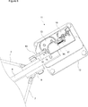
- Figure 5 is a detail view of the locking mechanism with the doors in open position.
- Figure 6 is a detail view of the locking mechanism with the doors in closed position.
- the oven (1) comprises a body (2), two French style side-by-side doors (4) enabling access into the cooking chamber (3) in the body (2), connected to the front surfaces of the opposite right and left vertical edges of the body (2) by means of hinges (19) so as to be pivotable about the vertical axis, and a linkage mechanism (6) mounted on a horizontal plane (5) on the upper or the lower wall of the body (2), interconnecting the doors (4) and enabling both doors (4) to be simultaneously opened by a user moving only one of the doors (4).
- the link mechanism (6) comprises two link arms (7) symmetrically connected by their front ends to the doors (4) so as to be pivotable about the vertical axis, moving parallel to the horizontal plane (5), and extending from both doors (4) by converging to each other towards the rear edge of the horizontal plane (5).
- the link arm (7) connected to the door (4) being opened or closed transmits its movement to the other (second) link arm (7) and therefore to the other (second) door (4), thereby enabling both doors (4) to be opened or closed simultaneously.
- the linkage mechanism (6) further comprises - a linear motion guide rail (8) (hereinafter referred to as ‘rail (8)’ in short) fixed on the horizontal plane (5) in parallel to the horizontal plane (5) by means of a front support plate (20) and a rear support plate (21), and - a carriage block (9) to which the rear ends of the link arms (7) are connected so as to be pivotable about the vertical axis, performing linear sliding motion on the rail (4) by means of a linear slide bearing between the rearmost position on the horizontal plane (5) in which the doors (4) are in the fully closed state and the foremost position in which the doors (4) are in the fully opened state.
- a linear motion guide rail (8) hereinafter referred to as ‘rail (8)’ in short
- the oven (1) of the invention comprises: - a locking tab (10) connected to the carriage block (9), moving in the horizontal direction together with the carriage block (9) during opening and closing of the doors (4), and - a locking mechanism (11) activated by the locking tab (10), enabling the doors (4) to be kept fixed in the closed position, while to be released when a user pulls the doors (4) with a force stronger than a given force.
- the carriage block (9) In the rearmost locking position the carriage block (9) reaches on the rail (8) when the doors (4) are brought to the closed position, the locking mechanism (11) activated by the locking tab (10) fixes the locking tab (10) by holding it with a given force.
- the carriage block (9) connected to the locking tab (10) and the link arms (7) connected to the carriage block (9) enable the doors (4) to be kept fixed in the closed position.
- Locking assemblies used separately for each door (4) are no longer required in the oven (1) of the invention. Both doors (4) are enabled to be kept fixed together in the closed position by means of a single locking mechanism (11) integrated to the linkage mechanism (6), such that they cannot be opened unless a user applies a given force.
- the force keeping the doors (4) in the closed and fixed state (or opening the doors (4)) is enabled to be easily adjusted by shifting the connection point of the locking tab (10) to the carriage block (9) or by changing the position of the locking tab (10) by means of screws or similar adjustment devices (not shown in the figures).
- the locking mechanism (11) comprises - a cam member (13) connected on a mounting plate (12) on the horizontal plane (5) so as to be pivotable about the vertical axis, - a recess (14) provided on the cam member (13), enabling the locking tab (10) reaching the locking position when the doors (4) are closed, to abut and to rotate the cam member (13), and - a retainer (15) enabling in the locking position, the locking tab (10) to be fixed (retained) by engaging a hole (22) on the locking tab (10) and the doors (4) to be kept closed such that they cannot to be opened under a given force by means of the carriage block (9) connected to the locking tab (10) and the link arms (7).
- the locking mechanism (11) comprises a cam follower (16) whose one end contacts the cam surfaces of the cam member (13), moving back and forth in the horizontal direction on the mounting plate (12) by the rotational motion of the cam member (13) during closing (locking) of the doors (4) and opening (releasing) of the doors (4), and a spring (17) connected to the cam follower (16), enabling continuous contact of the cam follower (16) to the cam member (13).
- the locking mechanism (11) comprises a switch (18) for example of a normally closed (nc.) or normally open (no.) type, fixed to the mounting plate (12), assuming on or off position by triggering of the cam follower (16) moving back and forth during closing and opening of the doors (4), detecting whether the doors (4) are fully closed sealingly or not.
- a switch (18) for example of a normally closed (nc.) or normally open (no.) type, fixed to the mounting plate (12), assuming on or off position by triggering of the cam follower (16) moving back and forth during closing and opening of the doors (4), detecting whether the doors (4) are fully closed sealingly or not.
- a control unit (not shown in the figures) does not allow the cooking process to be started in the oven (1) and alerts the user by audible/visible means.
- the control unit In an oven (1) with water washing or pyrolytic (high heat) cleaning features, upon the switch (18) transmitting a signal indicating that the doors (4) are not fully closed, the control unit does not start the water washing process or pyrolytic cleaning process in the oven (1) and alerts the user by audible/visible means.
Landscapes
- Engineering & Computer Science (AREA)
- Chemical & Material Sciences (AREA)
- Combustion & Propulsion (AREA)
- Mechanical Engineering (AREA)
- General Engineering & Computer Science (AREA)
- Electric Ovens (AREA)
Abstract
The present invention relates to an oven (1) comprising a body (2), two French style side-by-side doors (4) enabling access into the cooking chamber (3) in the body (2), connected to the front surfaces of the opposite right and left vertical edges of the body (2) by means of hinges (19) so as to be pivotable about the vertical axis, and a linkage mechanism (6) mounted on a horizontal plane (5) on the upper or the lower wall of the body (2), interconnecting the doors (4), enabling both doors (4) to be simultaneously opened by a user moving only one of the doors (4) and having - two link arms (7) symmetrically connected by their front ends to the doors (4) moving parallel to the horizontal plane (5), and extending from both doors (4) by converging to each other towards the rear edge of the horizontal plane (5), - a rail (8) fixed on the horizontal plane (5) in parallel to the horizontal plane (5) by means of a front support plate (20) and a rear support plate (21), and - a carriage block (9) to which the rear ends of the link arms (7) are connected, performing linear sliding motion on the rail (8), - a locking tab (10) connected to the carriage block (9), moving in the horizontal direction together with the carriage block (9) during opening and closing of the doors (4), and - a locking mechanism (11) activated by the locking tab (10), enabling the doors (4) to be kept fixed in the closed position, while to be released when the doors (4) are pulled with a force stronger than a given force.
Description
The present invention relates to an oven comprising French style doors positioned side-by-side.
Known oven doors are opened in up-down direction by being pivoted about the horizontal axis. The door of an oven is pulled outwards from the body by being held from its upper portion, and is brought to the horizontal and fully open position by being pivoted about the hinges with horizontal rotational axis provided on its lower edge. When the kitchen environment where the oven is being used lacks sufficient space, the area occupied by the door in horizontal position may create a problem for the users. In such a case, a user has to stand at the side of the oven to access the cooking volume when the oven door is fully opened. In the state of the art, ovens have been provided to solve this problem, comprising French style doors opening and closing by being pivoted about the vertical axis. In such type of ovens, symmetrically configured doors are used positioned side-by-side on the left and right sides. When one of the two French style side-by-side doors is opened and closed by a user, the other door also opens and closes simultaneously. A user can thus open both doors of the oven by a single hand, and can place into the oven the tray with the food products to be cooked thereon. Said simultaneous motion of French style doors is realized by a linkage mechanism coupling two doors to each other. These advantages of the French style doors are accompanied with certain disadvantages. Since a linkage mechanism consists of metal parts with rather high friction forces in between, a user has to apply a strong force to be able to open and close the doors. The doors closing simultaneously by means of a linkage mechanism are not able to provide a good sealing, therefore separate locking systems are used for each one of the doors.
Patent applications no. US2007039605 (A1) and US2009145031 (A1) disclose door linkage systems used in ovens having French style doors.
Patent application no. US2010206289 (A1) discloses locking systems in an oven, used separately for doors moving interdependently by means of a linkage system.
The aim of the present invention is to realize an oven comprising French style doors controlled by a linkage mechanism, having a locking mechanism enabling the doors to be kept closed so as not be opened under a given force.
The oven realized to achieve the aim of the present invention comprises two French style doors and a linkage mechanism provided on a horizontal plane on the upper or the lower wall of its body. The linkage mechanism enables both doors to be simultaneously opened or closed by a user pushing or pulling only one of the doors, and comprises two link arms connected to the doors, a carriage block to which the rear ends of the link arms are connected, and a rail on which the carriage block moves. The link arm connected to the door being opened or closed transmits its movement by means of the carriage block to the other link arm and therefore to the other door.
In the embodiment of the invention, the oven comprises a locking mechanism provided on the same plane as the linkage mechanism, operating by being triggered by a locking tab connected to the linkage mechanism, enabling the doors to be kept fixed in the closed position and to be released upon being pulled with a force stronger than a given force.
In an embodiment of the invention, the locking mechanism comprises a switch which switching to an on or off state during closing or opening of the doors, detecting whether the doors are sealingly closed or not.
The oven realized to achieve the aims of the present invention is illustrated in the accompanying drawings, wherein:
Figure 1 is a perspective view of an oven, linkage mechanism and a locking mechanism with the doors in closed position.
Figure 2 is a perspective view of an oven, linkage mechanism and a locking mechanism with the doors in open position.
Figure 3 is a view from above of an oven, linkage mechanism and a locking mechanism with the doors in closed position.
Figure 4 is a view from above of an oven, linkage mechanism and a locking mechanism with the doors in open position.
Figure 5 is a detail view of the locking mechanism with the doors in open position.
Figure 6 is a detail view of the locking mechanism with the doors in closed position.
The elements in the figures are numbered individually and the correspondence of these numbers are given hereinafter.
- Oven
- Body
- Cooking chamber
- Door
- Horizontal plane
- Linkage mechanism
- Link arm
- Rail
- Carriage block
- Locking tab
- Locking mechanism
- Mounting plate
- Cam member
- Recess
- Retainer
- Cam follower
- Spring
- Switch
- Hinge
- Front support plate
- Rear support plate
- Hole
The oven (1) comprises a body (2), two French style side-by-side doors (4) enabling access into the cooking chamber (3) in the body (2), connected to the front surfaces of the opposite right and left vertical edges of the body (2) by means of hinges (19) so as to be pivotable about the vertical axis, and a linkage mechanism (6) mounted on a horizontal plane (5) on the upper or the lower wall of the body (2), interconnecting the doors (4) and enabling both doors (4) to be simultaneously opened by a user moving only one of the doors (4).
The link mechanism (6) comprises two link arms (7) symmetrically connected by their front ends to the doors (4) so as to be pivotable about the vertical axis, moving parallel to the horizontal plane (5), and extending from both doors (4) by converging to each other towards the rear edge of the horizontal plane (5).
The link arm (7) connected to the door (4) being opened or closed transmits its movement to the other (second) link arm (7) and therefore to the other (second) door (4), thereby enabling both doors (4) to be opened or closed simultaneously.
The linkage mechanism (6) further comprises
- a linear motion guide rail (8) (hereinafter referred to as ‘rail (8)’ in short) fixed on the horizontal plane (5) in parallel to the horizontal plane (5) by means of a front support plate (20) and a rear support plate (21), and
- a carriage block (9) to which the rear ends of the link arms (7) are connected so as to be pivotable about the vertical axis, performing linear sliding motion on the rail (4) by means of a linear slide bearing between the rearmost position on the horizontal plane (5) in which the doors (4) are in the fully closed state and the foremost position in which the doors (4) are in the fully opened state.
- a linear motion guide rail (8) (hereinafter referred to as ‘rail (8)’ in short) fixed on the horizontal plane (5) in parallel to the horizontal plane (5) by means of a front support plate (20) and a rear support plate (21), and
- a carriage block (9) to which the rear ends of the link arms (7) are connected so as to be pivotable about the vertical axis, performing linear sliding motion on the rail (4) by means of a linear slide bearing between the rearmost position on the horizontal plane (5) in which the doors (4) are in the fully closed state and the foremost position in which the doors (4) are in the fully opened state.
The oven (1) of the invention comprises:
- a locking tab (10) connected to the carriage block (9), moving in the horizontal direction together with the carriage block (9) during opening and closing of the doors (4), and
- a locking mechanism (11) activated by the locking tab (10), enabling the doors (4) to be kept fixed in the closed position, while to be released when a user pulls the doors (4) with a force stronger than a given force.
- a locking tab (10) connected to the carriage block (9), moving in the horizontal direction together with the carriage block (9) during opening and closing of the doors (4), and
- a locking mechanism (11) activated by the locking tab (10), enabling the doors (4) to be kept fixed in the closed position, while to be released when a user pulls the doors (4) with a force stronger than a given force.
In the rearmost locking position the carriage block (9) reaches on the rail (8) when the doors (4) are brought to the closed position, the locking mechanism (11) activated by the locking tab (10) fixes the locking tab (10) by holding it with a given force. The carriage block (9) connected to the locking tab (10) and the link arms (7) connected to the carriage block (9) enable the doors (4) to be kept fixed in the closed position.
Locking assemblies used separately for each door (4) are no longer required in the oven (1) of the invention. Both doors (4) are enabled to be kept fixed together in the closed position by means of a single locking mechanism (11) integrated to the linkage mechanism (6), such that they cannot be opened unless a user applies a given force. The force keeping the doors (4) in the closed and fixed state (or opening the doors (4)) is enabled to be easily adjusted by shifting the connection point of the locking tab (10) to the carriage block (9) or by changing the position of the locking tab (10) by means of screws or similar adjustment devices (not shown in the figures).
The locking mechanism (11) comprises
- a cam member (13) connected on a mounting plate (12) on the horizontal plane (5) so as to be pivotable about the vertical axis,
- a recess (14) provided on the cam member (13), enabling the locking tab (10) reaching the locking position when the doors (4) are closed, to abut and to rotate the cam member (13), and
- a retainer (15) enabling in the locking position, the locking tab (10) to be fixed (retained) by engaging a hole (22) on the locking tab (10) and the doors (4) to be kept closed such that they cannot to be opened under a given force by means of the carriage block (9) connected to the locking tab (10) and the link arms (7).
- a cam member (13) connected on a mounting plate (12) on the horizontal plane (5) so as to be pivotable about the vertical axis,
- a recess (14) provided on the cam member (13), enabling the locking tab (10) reaching the locking position when the doors (4) are closed, to abut and to rotate the cam member (13), and
- a retainer (15) enabling in the locking position, the locking tab (10) to be fixed (retained) by engaging a hole (22) on the locking tab (10) and the doors (4) to be kept closed such that they cannot to be opened under a given force by means of the carriage block (9) connected to the locking tab (10) and the link arms (7).
In an embodiment of the invention, the locking mechanism (11) comprises a cam follower (16) whose one end contacts the cam surfaces of the cam member (13), moving back and forth in the horizontal direction on the mounting plate (12) by the rotational motion of the cam member (13) during closing (locking) of the doors (4) and opening (releasing) of the doors (4), and a spring (17) connected to the cam follower (16), enabling continuous contact of the cam follower (16) to the cam member (13).
In another embodiment of the invention, the locking mechanism (11) comprises a switch (18) for example of a normally closed (nc.) or normally open (no.) type, fixed to the mounting plate (12), assuming on or off position by triggering of the cam follower (16) moving back and forth during closing and opening of the doors (4), detecting whether the doors (4) are fully closed sealingly or not.
In another embodiment of the invention, upon the switch (18) transmitting a signal indicating that the doors (4) are not fully closed, a control unit (not shown in the figures) does not allow the cooking process to be started in the oven (1) and alerts the user by audible/visible means.
In an oven (1) with water washing or pyrolytic (high heat) cleaning features, upon the switch (18) transmitting a signal indicating that the doors (4) are not fully closed, the control unit does not start the water washing process or pyrolytic cleaning process in the oven (1) and alerts the user by audible/visible means.
Claims (6)
- An oven (1) comprising two French style side-by-side doors (4) enabling access into the cooking chamber (3) in a body (2), connected to the front surfaces of the opposite right and left vertical edges of the body (2) by means of hinges (19) so as to be pivotable about the vertical axis, and a linkage mechanism (6) mounted on a horizontal plane (5) on the upper or the lower wall of the body (2), enabling both doors (4) to be simultaneously opened by only one of the doors (4) being moved, the mechanism comprising- two link arms (7) symmetrically connected by their front ends to the to the doors (4), moving parallel to the horizontal plane (5), and extending from both doors (4) by converging to each other towards the rear edge of the horizontal plane (5),- a rail (8) fixed on the horizontal plane (5) in parallel to the horizontal plane (5) by means of a front support plate (20) and a rear support plate (21), and- a carriage block (9) to which the rear ends of the link arms (7) are connected, performing linear sliding motion on the rail (8), characterized by- a locking tab (10) connected to the carriage block (9), moving in the horizontal direction together with the carriage block (9) during opening and closing of the doors (4), and by- a locking mechanism (11) activated by the locking tab (10), enabling the doors (4) to be kept fixed in the closed position, while to be released when the doors (4) are pulled with a force stronger than a given force.
- An oven (1) according to claim 1, characterized by the locking mechanism (11) comprising on the horizontal plane (5) a cam member (13) connected on a mounting plate (12) so as to be pivotable about the vertical axis, a recess (14) provided on the cam member (13), enabling the locking tab (10) to abut and to rotate the cam member (13), a retainer (15) enabling the locking tab (10) to be fixed by engaging a hole (22) on the locking tab (10) in the locking position.
- An oven (1) according to claim 2, characterized by the locking mechanism (11) comprising a cam follower (16) whose one end contacts the cam surfaces of the cam member (13), moving back and forth in the horizontal direction on the mounting plate (12) by the rotational motion of the cam member (13), and a spring (17) connected to the cam follower (16), enabling continuous contact of the cam follower (16) to the cam member (13).
- An oven (1) according to claim 3, characterized by the locking mechanism (11) comprising a switch (18) fixed to the mounting plate (12), assuming on or off position by triggering of the cam follower (16) moving back and forth during closing and opening of the doors (4), detecting whether the doors (4) are fully closed sealingly or not.
- An oven (1) according to claim 4, characterized by a control unit not allowing the cooking process to be started and alerting the user by audible/visible means upon the switch (18) transmitting a signal indicating that the doors (4) are not fully closed.
- An oven (1) according to claim 4, characterized by a control unit not allowing the water washing process or the pyrolytic cleaning process to be started and alerting the user by audible/visible means upon the switch (18) transmitting a signal indicating that the doors (4) are not fully closed.
Applications Claiming Priority (2)
| Application Number | Priority Date | Filing Date | Title |
|---|---|---|---|
| TRA2018/02945 | 2018-03-01 | ||
| TR201802945 | 2018-03-01 |
Publications (1)
| Publication Number | Publication Date |
|---|---|
| WO2019166358A1 true WO2019166358A1 (en) | 2019-09-06 |
Family
ID=65628750
Family Applications (1)
| Application Number | Title | Priority Date | Filing Date |
|---|---|---|---|
| PCT/EP2019/054550 Ceased WO2019166358A1 (en) | 2018-03-01 | 2019-02-25 | An oven comprising french style doors |
Country Status (1)
| Country | Link |
|---|---|
| WO (1) | WO2019166358A1 (en) |
Cited By (1)
| Publication number | Priority date | Publication date | Assignee | Title |
|---|---|---|---|---|
| CN113334673A (en) * | 2021-04-28 | 2021-09-03 | 湖北龙运汽车配件有限公司 | Heating and curing device for brake pad production |
Citations (8)
| Publication number | Priority date | Publication date | Assignee | Title |
|---|---|---|---|---|
| US1827634A (en) * | 1930-01-20 | 1931-10-13 | Willoughby Mfg Co | Door holder |
| US2707225A (en) * | 1951-10-13 | 1955-04-26 | Gen Motors Corp | Electric range |
| US3216776A (en) * | 1963-10-22 | 1965-11-09 | Gen Electric | Refrigerator cabinet |
| FR2359378A1 (en) * | 1976-07-22 | 1978-02-17 | Litton Industries Inc | MIXED COOKER CAPABLE OF COOKING FOOD BY RELEASE OF THERMAL ENERGY AS WELL AS BY HIGH FREQUENCY WAVES |
| US20070039605A1 (en) | 2005-08-18 | 2007-02-22 | Maytag Corp. | Door linkage system for an oven having french-style doors |
| US20090145031A1 (en) | 2007-12-06 | 2009-06-11 | Collene James J | French door hinge system for oven |
| US20100206289A1 (en) | 2005-08-18 | 2010-08-19 | Whirlpool Corporation | Door locking mechanism for an oven having french-style doors |
| CN105889995A (en) * | 2016-06-12 | 2016-08-24 | 广东美的厨房电器制造有限公司 | Interlocking switch structure and microwave oven |
-
2019
- 2019-02-25 WO PCT/EP2019/054550 patent/WO2019166358A1/en not_active Ceased
Patent Citations (8)
| Publication number | Priority date | Publication date | Assignee | Title |
|---|---|---|---|---|
| US1827634A (en) * | 1930-01-20 | 1931-10-13 | Willoughby Mfg Co | Door holder |
| US2707225A (en) * | 1951-10-13 | 1955-04-26 | Gen Motors Corp | Electric range |
| US3216776A (en) * | 1963-10-22 | 1965-11-09 | Gen Electric | Refrigerator cabinet |
| FR2359378A1 (en) * | 1976-07-22 | 1978-02-17 | Litton Industries Inc | MIXED COOKER CAPABLE OF COOKING FOOD BY RELEASE OF THERMAL ENERGY AS WELL AS BY HIGH FREQUENCY WAVES |
| US20070039605A1 (en) | 2005-08-18 | 2007-02-22 | Maytag Corp. | Door linkage system for an oven having french-style doors |
| US20100206289A1 (en) | 2005-08-18 | 2010-08-19 | Whirlpool Corporation | Door locking mechanism for an oven having french-style doors |
| US20090145031A1 (en) | 2007-12-06 | 2009-06-11 | Collene James J | French door hinge system for oven |
| CN105889995A (en) * | 2016-06-12 | 2016-08-24 | 广东美的厨房电器制造有限公司 | Interlocking switch structure and microwave oven |
Cited By (1)
| Publication number | Priority date | Publication date | Assignee | Title |
|---|---|---|---|---|
| CN113334673A (en) * | 2021-04-28 | 2021-09-03 | 湖北龙运汽车配件有限公司 | Heating and curing device for brake pad production |
Similar Documents
| Publication | Publication Date | Title |
|---|---|---|
| US8327835B2 (en) | Door locking mechanism for an oven having french-style doors | |
| US2997041A (en) | Cooking oven | |
| US3955865A (en) | Oven door counterbalance system | |
| US7814897B2 (en) | Door linkage system for an oven having french-style doors | |
| EP3686530B1 (en) | Refrigerator | |
| EP2534325B1 (en) | Hinge mechanism for a home appliance providing door motion in a non-circular path | |
| US5960785A (en) | Cooking range oven having insulated oven door with viewing system | |
| EP1776914B1 (en) | Magnetic latch for movable receptacle | |
| CN110582676B (en) | Cooking appliance with a cable pull for automatically pivoting the door | |
| AU2015279232A1 (en) | Domestic oven having a door with two door wings | |
| US20140225492A1 (en) | Fitting for corner cabinets and pull-in device for said type of fitting | |
| US20150354829A1 (en) | Oven appliance | |
| GB1584051A (en) | Domestic cooking appliance | |
| KR100498116B1 (en) | Grill | |
| EP4007870B1 (en) | Vertical hood | |
| KR101898797B1 (en) | Apparatus for supporting shelf and cooking appliance therewith | |
| WO2018207063A1 (en) | Hinge for home appliance | |
| EP1834026A2 (en) | A household appliance | |
| US20150354830A1 (en) | Oven appliance | |
| US20210121042A1 (en) | Domestic dishwasher | |
| US1885404A (en) | Oven rack operating mechanism | |
| WO2019166363A1 (en) | Linkage mechanism suitable to be used in an oven comprising french style doors | |
| EP2933567B1 (en) | Household cooking appliance | |
| EP0447374A2 (en) | A movable member, normally indistinguishable from the surrounding surface of an oven or other appliance, in particular built-in ones, adapted to perform as a handle for pulling out a drawer, shelf or the like | |
| US12426134B2 (en) | Interlock system with hinge connection for appliance door |
Legal Events
| Date | Code | Title | Description |
|---|---|---|---|
| 121 | Ep: the epo has been informed by wipo that ep was designated in this application |
Ref document number: 19708263 Country of ref document: EP Kind code of ref document: A1 |
|
| NENP | Non-entry into the national phase |
Ref country code: DE |
|
| 122 | Ep: pct application non-entry in european phase |
Ref document number: 19708263 Country of ref document: EP Kind code of ref document: A1 |