WO2019151200A1 - Motor control device and electric power steering device equipped with same - Google Patents

Motor control device and electric power steering device equipped with same Download PDF

Info

Publication number
WO2019151200A1
WO2019151200A1 PCT/JP2019/002845 JP2019002845W WO2019151200A1 WO 2019151200 A1 WO2019151200 A1 WO 2019151200A1 JP 2019002845 W JP2019002845 W JP 2019002845W WO 2019151200 A1 WO2019151200 A1 WO 2019151200A1
Authority
WO
WIPO (PCT)
Prior art keywords
axis
motor
value
command value
dead time
Prior art date
Application number
PCT/JP2019/002845
Other languages
French (fr)
Japanese (ja)
Inventor
博明 高瀬
亮 皆木
孝義 菅原
Original Assignee
日本精工株式会社
Priority date (The priority date is an assumption and is not a legal conclusion. Google has not performed a legal analysis and makes no representation as to the accuracy of the date listed.)
Filing date
Publication date
Application filed by 日本精工株式会社 filed Critical 日本精工株式会社
Priority to CN201980002414.9A priority Critical patent/CN110651425B/en
Priority to JP2019555989A priority patent/JP6658995B2/en
Priority to BR112019022003-8A priority patent/BR112019022003A2/en
Priority to EP19748122.9A priority patent/EP3598632A4/en
Priority to US16/605,874 priority patent/US11101756B2/en
Publication of WO2019151200A1 publication Critical patent/WO2019151200A1/en

Links

Images

Classifications

    • HELECTRICITY
    • H02GENERATION; CONVERSION OR DISTRIBUTION OF ELECTRIC POWER
    • H02PCONTROL OR REGULATION OF ELECTRIC MOTORS, ELECTRIC GENERATORS OR DYNAMO-ELECTRIC CONVERTERS; CONTROLLING TRANSFORMERS, REACTORS OR CHOKE COILS
    • H02P21/00Arrangements or methods for the control of electric machines by vector control, e.g. by control of field orientation
    • H02P21/13Observer control, e.g. using Luenberger observers or Kalman filters
    • BPERFORMING OPERATIONS; TRANSPORTING
    • B62LAND VEHICLES FOR TRAVELLING OTHERWISE THAN ON RAILS
    • B62DMOTOR VEHICLES; TRAILERS
    • B62D5/00Power-assisted or power-driven steering
    • B62D5/04Power-assisted or power-driven steering electrical, e.g. using an electric servo-motor connected to, or forming part of, the steering gear
    • B62D5/0457Power-assisted or power-driven steering electrical, e.g. using an electric servo-motor connected to, or forming part of, the steering gear characterised by control features of the drive means as such
    • B62D5/046Controlling the motor
    • B62D5/0463Controlling the motor calculating assisting torque from the motor based on driver input
    • BPERFORMING OPERATIONS; TRANSPORTING
    • B62LAND VEHICLES FOR TRAVELLING OTHERWISE THAN ON RAILS
    • B62DMOTOR VEHICLES; TRAILERS
    • B62D5/00Power-assisted or power-driven steering
    • B62D5/04Power-assisted or power-driven steering electrical, e.g. using an electric servo-motor connected to, or forming part of, the steering gear
    • B62D5/0457Power-assisted or power-driven steering electrical, e.g. using an electric servo-motor connected to, or forming part of, the steering gear characterised by control features of the drive means as such
    • B62D5/0481Power-assisted or power-driven steering electrical, e.g. using an electric servo-motor connected to, or forming part of, the steering gear characterised by control features of the drive means as such monitoring the steering system, e.g. failures
    • B62D5/0487Power-assisted or power-driven steering electrical, e.g. using an electric servo-motor connected to, or forming part of, the steering gear characterised by control features of the drive means as such monitoring the steering system, e.g. failures detecting motor faults
    • BPERFORMING OPERATIONS; TRANSPORTING
    • B62LAND VEHICLES FOR TRAVELLING OTHERWISE THAN ON RAILS
    • B62DMOTOR VEHICLES; TRAILERS
    • B62D6/00Arrangements for automatically controlling steering depending on driving conditions sensed and responded to, e.g. control circuits
    • HELECTRICITY
    • H02GENERATION; CONVERSION OR DISTRIBUTION OF ELECTRIC POWER
    • H02PCONTROL OR REGULATION OF ELECTRIC MOTORS, ELECTRIC GENERATORS OR DYNAMO-ELECTRIC CONVERTERS; CONTROLLING TRANSFORMERS, REACTORS OR CHOKE COILS
    • H02P21/00Arrangements or methods for the control of electric machines by vector control, e.g. by control of field orientation
    • H02P21/05Arrangements or methods for the control of electric machines by vector control, e.g. by control of field orientation specially adapted for damping motor oscillations, e.g. for reducing hunting
    • HELECTRICITY
    • H02GENERATION; CONVERSION OR DISTRIBUTION OF ELECTRIC POWER
    • H02PCONTROL OR REGULATION OF ELECTRIC MOTORS, ELECTRIC GENERATORS OR DYNAMO-ELECTRIC CONVERTERS; CONTROLLING TRANSFORMERS, REACTORS OR CHOKE COILS
    • H02P21/00Arrangements or methods for the control of electric machines by vector control, e.g. by control of field orientation
    • H02P21/22Current control, e.g. using a current control loop
    • HELECTRICITY
    • H02GENERATION; CONVERSION OR DISTRIBUTION OF ELECTRIC POWER
    • H02PCONTROL OR REGULATION OF ELECTRIC MOTORS, ELECTRIC GENERATORS OR DYNAMO-ELECTRIC CONVERTERS; CONTROLLING TRANSFORMERS, REACTORS OR CHOKE COILS
    • H02P27/00Arrangements or methods for the control of AC motors characterised by the kind of supply voltage
    • H02P27/04Arrangements or methods for the control of AC motors characterised by the kind of supply voltage using variable-frequency supply voltage, e.g. inverter or converter supply voltage
    • H02P27/06Arrangements or methods for the control of AC motors characterised by the kind of supply voltage using variable-frequency supply voltage, e.g. inverter or converter supply voltage using dc to ac converters or inverters
    • H02P27/08Arrangements or methods for the control of AC motors characterised by the kind of supply voltage using variable-frequency supply voltage, e.g. inverter or converter supply voltage using dc to ac converters or inverters with pulse width modulation
    • H02P27/12Arrangements or methods for the control of AC motors characterised by the kind of supply voltage using variable-frequency supply voltage, e.g. inverter or converter supply voltage using dc to ac converters or inverters with pulse width modulation pulsing by guiding the flux vector, current vector or voltage vector on a circle or a closed curve, e.g. for direct torque control

Definitions

  • the present invention relates to a motor control device that performs vector control of a three-phase brushless motor using a dq axis rotation coordinate system and compensates for dead time of an inverter, and an electric power steering device equipped with the motor control device, and more particularly to dq axis dead time compensation.
  • the dq axis disturbance estimation observer estimates the disturbance that cannot be compensated for by dead time compensation, and further performs space vector modulation to further improve the performance of steering response, abnormal noise and vibration of the motor, and torque ripple.
  • the present invention relates to a motor control device that improves responsiveness and noise resistance in accordance with the number, increases the motor model accuracy in response to a dq-axis current command value, and improves compensation accuracy, and an electric power steering device equipped with the motor control device.
  • Motor control devices that control objects by driving motors are mounted on electric power steering devices (EPS), electric assist bicycles, trains, electric cars, and the like.
  • An electric power steering device that is equipped with a motor control device and applies a steering assist force (assist force) to the steering mechanism of the vehicle by the rotational force of the motor is used to drive the driving force of the motor as an actuator to a gear or belt via a speed reducer.
  • a steering assist force is applied to the steering shaft or the rack shaft by a transmission mechanism such as the above.
  • Such a conventional electric power steering apparatus performs feedback (FB) control of the motor current in order to accurately generate the torque of the steering assist force.
  • FB feedback
  • the motor applied voltage is adjusted so that the difference between the steering assist command value (current command value) and the motor current detection value becomes small.
  • PWM Pulse Width
  • Modulation is performed by adjusting the duty of control.
  • the general configuration of the electric power steering apparatus will be described with reference to FIG. 6b is further connected to the steering wheels 8L and 8R via hub units 7a and 7b.
  • the column shaft 2 is provided with a steering angle sensor 14 for detecting the steering angle ⁇ h of the handle 1 and a torque sensor 10 for detecting the steering torque Th of the handle 1 to assist the steering force of the handle 1.
  • a motor 20 is connected to the column shaft 2 via the reduction gear 3.
  • the control unit (ECU) 30 that controls the electric power steering apparatus is supplied with electric power from the battery 13 and also receives an ignition key signal via the ignition key 11.
  • the control unit 30 calculates the current command value of the assist (steering assistance) command based on the steering torque Th detected by the torque sensor 10 and the vehicle speed Vs detected by the vehicle speed sensor 12, and the calculated current command value
  • the current supplied to the motor 20 is controlled by the voltage control command value Vref for which compensation has been applied.
  • the steering angle sensor 14 is not essential and may not be provided, and the steering angle (motor rotation angle) ⁇ can be obtained from a rotation sensor such as a resolver connected to the motor 20.
  • the control unit 30 is connected to a CAN (Controller Area Network) 40 that exchanges various vehicle information, and the vehicle speed Vs can be received from the CAN 40.
  • the control unit 30 can be connected to a non-CAN 41 that exchanges communications, analog / digital signals, radio waves, and the like other than the CAN 40.
  • control unit 30 is mainly composed of a CPU (Central Processing Unit) (including MPU (Micro Processor Unit), MCU (Micro Controller Unit), etc.).
  • CPU Central Processing Unit
  • MPU Micro Processor Unit
  • MCU Micro Controller Unit
  • FIG. 2 A general function to be executed is shown in FIG. 2, for example.
  • the function and operation of the control unit 30 will be described with reference to FIG. 2.
  • the steering torque Th from the torque sensor 10 and the vehicle speed Vs from the vehicle speed sensor 12 are input to the steering assist command value calculation unit 31 to calculate the steering assist command value.
  • the unit 31 calculates a steering assist command value Iref1 using an assist map or the like based on the steering torque Th and the vehicle speed Vs.
  • the calculated steering assist command value Iref1 is added by the adder 32A and the compensation signal CM from the compensator 34 for improving characteristics, and the added steering assist command value Iref2 limits the maximum value by the current limiter 33.
  • the current command value Irefm whose maximum value is limited is input to the subtraction unit 32B, and is subtracted from the motor current detection value Im.
  • the duty command value is input to the PWM controller 36 together with the carrier (CF) and the duty command value is calculated, and the motor 20 is PWM-driven via the inverter 37 with the PWM signal calculated from the duty command value.
  • the motor current value Im of the motor 20 is detected by the motor current detector 38, and is input to the subtraction unit 32B and fed back.
  • the compensator 34 adds the detected or estimated SAT (Self-Aligning Torque) to the inertia compensation value 342 by the adder 344, and further adds the convergence control value 341 to the addition result by the adder 345.
  • the result is input to the adder 32A as a compensation signal CM to improve the characteristics.
  • the current waveform is distorted, and the current control response and steering feel deteriorate.
  • the current control response and steering feel deteriorate.
  • the steering is slowly performed with the steering wheel in the vicinity of the on-center, discontinuous steering feeling due to torque ripple or the like occurs.
  • the back electromotive voltage of the motor during middle / high speed steering and the interference voltage between the windings act as disturbances on the current control, the followability and the steering feeling during turn-back steering are deteriorated. Steering noise also deteriorates during medium and high speed steering.
  • the q-axis that controls the torque of the rotor of the three-phase brushless motor and the d-axis that controls the strength of the magnetic field are set independently, and the dq-axis has a 90 ° relationship.
  • a vector control method for controlling currents d-axis current command value and q-axis current command value).
  • FIG. 3 shows a configuration example when the three-phase brushless motor 100 is driven and controlled by the vector control method, and is calculated by a steering assist command value calculation unit (not shown) based on the steering torque Th, the vehicle speed Vs, and the like.
  • the two-axis (dq-axis coordinate system) steering assist command value is calculated, and the two-axis d-axis current command value id * and q-axis current command value iq * whose maximum values are limited are respectively supplied to the subtracting units 131d and 131q.
  • the deviation currents ⁇ id * and ⁇ iq * that are input and obtained by the subtraction units 131d and 131q are input to the PI control units 120d and 120q, respectively.
  • Voltage command values vd and vq PI-controlled by PI (Proportional-Integral) control units 120d and 120q are input to a subtraction unit 121d and an addition unit 121q, respectively, and a command voltage ⁇ vd obtained by the subtraction unit 121d and the addition unit 121q. And ⁇ vq are input to the dq axis / 3-phase AC converter 150.
  • the voltage command values Vu * , Vv * , Vw * converted into three phases by the dq axis / 3-phase AC converter 150 are input to the duty command value calculator 160A in the PWM controller 160 and synchronized with the modulation signal CF.
  • the three-phase duty command values Duty, Dutyv, and Dutyw calculated in this manner are input to the PWM control circuit 160B.
  • the PWM control circuit 160B generates three-phase PWM signals U PWM , V PWM and W PWM , and the PWM signal passes through an inverter (inverter applied voltage VR) 161 having a bridge configuration of upper and lower arms as shown in FIG.
  • the motor 100 is driven.
  • the upper arm is composed of FETs Q1, Q3, and Q5 as switching elements, and the lower arm is composed of FETs Q2, Q4, and Q6.
  • the three-phase motor currents iu, iv, iw of the motor 100 are detected by the current detector 162, and the detected three-phase motor currents iu, iv, iw are input to the three-phase AC / dq axis conversion unit 130, and the three-phase AC
  • the two-phase feedback currents id and iq converted by the / dq axis conversion unit 130 are subtracted and input to the subtraction units 131d and 131q, respectively, and also input to the dq axis non-interference control unit 140.
  • a rotation sensor or the like is attached to the motor 100, and the motor rotation angle ⁇ and the motor angular velocity ⁇ are output from the angle detection unit 110 that processes the sensor signal.
  • the motor rotation angle ⁇ is input to the dq axis / three-phase AC conversion unit 150 and the three-phase AC / dq axis conversion unit 130, and the motor angular velocity ⁇ is input to the dq axis non-interference control unit 140.
  • the two-phase voltages Vnid and Vniq from the dq axis non-interference control unit 140 are respectively input to the subtraction unit 121d and the addition unit 121q, the voltage command value ⁇ vd obtained by the subtraction unit 121d and the voltage command obtained by the addition unit 121q.
  • the value ⁇ vq is input to the dq axis / 3-phase AC converter 150.
  • Such an electric power steering device of the vector control system is a device that assists the driver's steering, and at the same time, the sound, vibration, torque ripple, etc. of the motor are transmitted to the driver as a sense of force through the steering wheel.
  • FET Field-Effect Transistor
  • the motor is energized.
  • FIG. A series-connected FET of arms is used.
  • the FETs of the upper and lower arms alternately repeat the ON operation and the OFF operation, but the FET is not an ideal switch and does not instantaneously perform the ON operation and the OFF operation according to the command of the gate signal, and requires a turn-on time and a turn-off time. For this reason, when an ON command to the upper arm FET and an OFF command to the lower arm are simultaneously issued, there is a problem that the upper arm FET and the lower arm FET are simultaneously turned on, and the upper and lower arms are short-circuited.
  • an ON signal is given to the gate drive circuit after a predetermined time called a dead time so that the upper arm FET and the lower arm FET are not turned ON at the same time. Since this dead time is non-linear, the current waveform is distorted, the response performance of the control is deteriorated, and sound, vibration, and ripple are generated.
  • the arrangement of the motor directly connected to the gear box connected to the steering wheel and the steel column shaft is very close to the driver due to its structure, resulting in the motor. Sound, vibration, torque ripple, and the like need to be particularly considered compared to a downstream assist type electric power steering apparatus as shown in FIG.
  • the motor 20 operates the reduction gear 3 via the belt 21.
  • the timing at which the dead time occurs is detected and the compensation value is added, or the dead time is compensated by a disturbance observer on the dq axis in current control.
  • Patent Document 1 An electric power steering device that compensates for the dead time of an inverter is disclosed in, for example, Japanese Patent No. 4681453 (Patent Document 1) and Japanese Patent Application Laid-Open No. 2015-171251 (Patent Document 2).
  • Patent Document 1 a current command value is input to a reference model circuit of a current control loop including a motor and an inverter, a model current is created based on the current command value, and the effect of the inverter dead time is compensated based on the model current.
  • a dead band compensation circuit is provided.
  • Patent Document 2 includes a dead time compensation unit that performs correction based on the dead time compensation value for the duty command value, and calculates a basic compensation value that is a basic value of the dead time compensation value based on the current command value.
  • a basic compensation value calculation unit and a filter unit that performs filtering processing corresponding to the LPF on the basic compensation value.
  • the apparatus of Patent Document 1 is a method for estimating a compensation code by using a calculation of a dead time compensation amount based on the magnitude of a q-axis current command value and a three-phase current reference model.
  • the output value of the compensation circuit When the output value of the compensation circuit is below a predetermined fixed value, it is a change value proportional to the model current.
  • the output value When the output value is above the predetermined fixed value, it is the sum of the fixed value and the change value proportional to the model current.
  • tuning work is required to determine the hysteresis characteristic for outputting a predetermined fixed value.
  • the device of Patent Document 2 when determining the dead time compensation value, performs dead time compensation with the q-axis current command value and the compensation value obtained by LPF processing of the q-axis current command value.
  • the dead time compensation value is not manipulated for a correct voltage command.
  • Patent Document 3 JP 2007-252163 A (Patent Document 3) discloses that dead time compensation is performed by a disturbance estimation observer.
  • the disturbance observer on the dq axis estimates the dead time as a voltage disturbance, there is a problem that the effect is not sufficient because the third-order component signal is removed in the dq axis / 3-phase coordinate conversion. .
  • the current distortion due to the dead time may change due to individual differences of the ECU or deterioration over time.
  • the dq axis non-interference control alone causes variations in counter electromotive voltage due to counter electromotive voltages other than the primary component and individual differences (general variations are, for example, 2.6 [V] / per phase variation of the primary component) 1000 [rpm] Back electromotive force ( ⁇ 3%) and other variations that can not be handled, when the primary component is 100%, the variation of the 5th and 7th components is ⁇ 0.3% (% differs for each motor), etc.
  • the fifth / seventh component may not be converted to the sixth component, and transient steering input (for example, sudden steering such as step input) If you have a momentary cut from 0 ° to 90 ° and stop at 90 °), or if you follow a rapid reverse input from the tire), you cannot follow the PI control and dq axis non-interference control alone. There may be cases (delay of output system / detection system, compensation using rotation speed) Positive function delay etc.).
  • the responsiveness of current control (PI control alone) is, for example, 300 Hz (when PI control responsiveness is fixed). When the responsiveness variable function is enabled, the responsiveness of PI control is made variable according to the motor speed.
  • the frequency is 80 Hz (during steering) to 450 Hz (during high-speed steering).
  • the response of the PI control is lowered to reduce the holding vibration, and at the time of high speed steering, the response of the PI control is raised to improve the following ability.
  • the present invention has been made under the circumstances described above, and an object of the present invention is to compensate for a dead time of an inverter in a vector control type motor control device, and a disturbance that cannot be fully compensated by dead time compensation (described later). ) Is estimated to improve current waveform distortion and current control response, and to provide a motor control device that suppresses motor noise, vibration, and torque ripple, and an electric power steering device equipped with the motor control device. It is in.
  • the three-phase brushless motor is vector-controlled based on the d-axis current command value and the q-axis current command value, and the three-phase current detection value of the three-phase brushless motor is converted into the d-axis feedback current and the q-axis feedback current.
  • the object of the present invention is to provide a dq axis dead time compensator for calculating a dead time compensation value of the inverter and performing dead time compensation, the dq axis current command value, and a motor.
  • a dq-axis disturbance estimation observer that inputs the rotation speed, the dq-axis feedback current, and the deviation voltage, and calculates and outputs a dq-axis disturbance compensation value Comprising the door, by adding the dq Jikugairan compensation value to the difference voltage is achieved by estimating the disturbance that can not be compensated by the dead time compensation of the inverter.
  • the present invention vector-controls a three-phase brushless motor based on the d-axis current command value and the q-axis current command value, and uses the three-phase current detection value of the three-phase brushless motor as a d-axis feedback current and a q-axis feedback.
  • the current is converted into a current to control each deviation current between the d-axis current command value and the q-axis current command value to obtain a d-axis voltage command value and a q-axis voltage command value, and the d-axis voltage command value and the
  • the present invention relates to a motor control device that controls the three-phase brushless motor via an inverter using a three-phase duty command value based on a q-axis voltage command value.
  • the object of the present invention is to calculate a dead time compensation value of the inverter.
  • a d-axis dead time compensator and a q-axis dead time compensator for performing compensation the d-axis current command value; the d-axis voltage command value; the d-axis feedback current;
  • the d-axis non-interference model that inputs the q-axis feedback current and the motor angular velocity, and the output of the d-axis non-interference model to the first d-axis addition value of the d-axis disturbance compensation value and the d-axis voltage command value
  • a d-axis LPF that inputs a second d-axis addition value
  • a d-axis motor inverse model that inputs the d-axis feedback current, and the d-axis motor from the output of the d-axis LPF
  • a d-axis subtraction unit that subtracts the output of the model to obtain a d-axis deviation voltage
  • a d-axis sensitive gain unit that multiplies the d-axis deviation voltage according to the motor speed
  • a q-axis non-interference model in which the q-axis disturbance estimation observer inputs the d-axis feedback current and the motor
  • a q-axis LPF for inputting a q-axis subtraction value obtained by subtracting the output of the q-axis non-interference model from a first q-axis addition value of the q-axis disturbance compensation value and the q-axis voltage command value; and the q-axis feedback
  • a q-axis motor inverse model for inputting current, a q-axis subtractor for subtracting the output of the q-axis motor inverse model from the output of the q-axis LPF to obtain a q-axis deviation voltage, and the q-axis deviation voltage for the motor Gain doubled according to rotation speed
  • an electric power steering device which is equipped with the motor control device and applies assist torque to the vehicle steering system by driving the three-phase brushless motor.
  • the back electromotive force voltage is different from the design value when the deviation from the dead time compensation value set at the time of design due to individual differences of ECUs or aging deterioration, or due to the back electromotive voltage or individual differences of motors. Even in the case of deviation, dead time compensation and counter electromotive voltage compensation for the deviation value are possible.
  • dead time compensation and counter electromotive voltage compensation for the deviation value are possible.
  • the disturbance estimation observer has a delay from the detection of the disturbance to the reflection, so the compensation may not be in time.However, if the disturbance due to dead time is reduced in advance by dead time compensation, the observer will detect the remaining disturbance. Focus on estimation and make it easier to compensate.
  • the LPF for limiting the band of the disturbance estimation observer and the cutoff frequency of the motor inverse model are varied according to the motor rotation speed, so that the responsiveness and noise resistance can be improved. Since the inductance component (inductance nominal value) of the motor inverse model of the disturbance estimation observer is varied in response to the dq-axis current command value, the motor model accuracy can be improved, and the dead time according to the dq-axis current command value The accuracy of compensation can be further improved.
  • the rough current distortion is improved by the dead time compensation function and the dq axis non-interference control, there is a concern that the current distortion due to the dead time may change due to individual differences of the ECU or deterioration over time. In some cases, it is not possible to cope with variations in counter electromotive voltage due to motor counter electromotive voltage compensation other than the primary component and individual differences between motors. In addition, when there is a transient steering input, there is a problem that dq axis non-interference control and PI control alone cannot be followed due to delays in the output system and detection system and the correction function using the motor speed. is there.
  • dq axis non-interference is considered in the present invention for the purpose of improving current response that cannot be followed by dead time compensation, dq axis non-interference control and PI control, and control response.
  • a configuration of an axial disturbance estimation observer is proposed.
  • the cut-off frequency of the LPF for limiting the bandwidth of the dq axis disturbance estimation observer is varied according to the motor rotation speed to improve the response and noise resistance, and to respond to the dq axis current command value.
  • the inductance component (inductance nominal value) of the motor inverse model is varied to improve the model accuracy and further improve the accuracy of dead time compensation.
  • the motor control device according to the present invention can be applied to an electrically assisted bicycle, a train, an electric vehicle, etc.
  • an example in which the motor control device is mounted on an electric power steering device will be described.
  • FIG. 6 shows the overall configuration of the present invention in correspondence with FIG. 3.
  • a dq-axis disturbance estimation observer 600 is provided which inputs Vd2 and Vq2 and outputs dq-axis disturbance compensation values Vcmp_d and Vcmp_q.
  • adders 122d and 122q are provided, and adders 123d and 123q are further provided in the subsequent stage.
  • the dq axis disturbance compensation values Vcmp_d and Vcmp_q are input to the adders 122d and 122q, respectively.
  • a dq axis dead time compensation unit 200 for inputting a motor terminal voltage or the like and calculating the dead time compensation values Vd * and Vq * on the dq axis is provided.
  • Dead time compensation values Vd * and Vq * are input to adders 123d and 123q, respectively.
  • the motor rotation speed rpm is calculated by differentiating the angle by the angle detection unit 110.
  • the motor angular velocity ⁇ is calculated by the angle detection unit 110.
  • the unit is [rad / s]
  • the motor angular velocity ⁇ is used in the current control calculation.
  • the motor rotational speed rpm is a mechanical angular rotational speed, the unit of which is [rpm], and is used for changing control conditions.
  • the motor rotation speed rpm is used as a control condition so as to be understood by a human sense.
  • the d-axis current command value id * and the q-axis current command value iq * which are limited in the maximum value of the steering assist command value calculated by the steering assist command value calculation unit (not shown), are input to the subtraction units 131d and 131q, respectively.
  • the deviation currents ⁇ id * and ⁇ iq * calculated by the subtraction units 131d and 131q are PI-controlled by the PI control units 120d and 120q, respectively, and the dq-axis voltages vd and vq subjected to PI control (current control) are subtracted by the subtraction units 121d and The data is input to the adding unit 121q.
  • Voltages Vnid and Vniq are respectively input from the dq axis non-interference control unit 140 to the subtraction unit 121d and the addition unit 121q.
  • the value Vq1 is input to the adders 122d and 122q, respectively, and the voltage command values Vd2 and Vq2 added to the dq axis disturbance compensation values Vcmp_d and Vcmp_q by the adders 122d and 122q are input to the adders 123d and 123q, respectively.
  • it is input to the dq axis disturbance estimation observer 600.
  • the voltage command values Vd3 and Vq3 added to the dead time compensation values Vd * and Vq * by the adders 123d and 123q, respectively, are input to the duty calculation unit 700, and calculated by the duty calculation unit 700 in synchronization with the modulation signal CF.
  • the dq-axis Duty values Duty_d ** and Duty_q ** are input to the space vector modulation unit 300 (described in detail later).
  • the three-phase duty values Duty_u * , Duty_v * , and Duty_w * vector-modulated by the space vector modulation unit 300 are input to the PWM control unit 160, and the motor 100 is driven via the PWM control unit 160 and the inverter 161 in the same manner as described above. Be controlled.
  • FIG. 7 shows details of the dead time compensation system including the dq axis disturbance estimation observer 600 (first embodiment).
  • the dq axis disturbance estimation observer 600 includes a d axis disturbance estimation observer 600d and a q axis disturbance estimation observer 600q.
  • the dq-axis dead time compensation unit 200 includes a d-axis dead time compensation unit 200d and a q-axis dead time compensation unit 200q.
  • the dq-axis non-interference control unit 140 includes a d-axis non-interference control unit 140d and a q-axis non-interference control unit 140q.
  • a motor angular velocity ⁇ and a q-axis feedback current iq are input to the d-axis non-interference control unit 140d.
  • the q-axis non-interference control unit 140q receives the motor angular velocity ⁇ and the d-axis feedback current id.
  • the d-axis non-interference control unit 140d includes a multiplication unit 141d and a constant unit 142d (Lq), and the q-axis non-interference control unit 140q includes a multiplication unit 141q, constant units 142q (Ld) and 143q ( ⁇ ), and an addition unit 144q. It is configured.
  • the d-axis disturbance estimation observer 600d includes a primary band limiting LPF (Low Pass Filter) 601d for inputting the voltage command value vd2 from the adder 122d, and a d-axis motor inverse model 602d for inputting the d-axis feedback current id.
  • a d-axis non-interference model 610d for inputting the motor angular velocity ⁇ and the q-axis feedback current iq
  • an LPF 603d for inputting the voltage Vdb from the d-axis non-interference model 610d
  • a voltage Vda and LPF 603d from the d-axis motor inverse model 602d.
  • a sensitivity gain unit 605d that multiplies a gain Gd that is sensitive to the motor speed rpm, and a voltage Vdse from the sensitivity gain unit 605d. It is composed of a compensation amount limiting section 604d which outputs the d Jikugairan compensation value Vcmp_d limits the limit value.
  • the d-axis non-interference model 610d includes a multiplication unit 612d that inputs the motor angular velocity ⁇ and the q-axis feedback current iq, and a constant unit 611d that outputs the voltage Vdb by multiplying the multiplication result of the multiplication unit 612d by a constant (Lqn). Has been.
  • the q-axis disturbance estimation observer 600q has substantially the same configuration as the d-axis disturbance estimation observer 600d, and the corresponding part is shown by replacing the code “d” with the code “q”, but the input code of the adder 607q and the q Only the configuration of the axis non-interference model 610q is different.
  • the q-axis non-interference model 610q in the adder 607q and the q-axis disturbance estimation observer 600q includes a multiplier 612q that inputs the motor angular velocity ⁇ and the d-axis feedback current id, and a multiplication result of the multiplier 612q by a constant multiple (Ldn ), A constant unit 613q that multiplies the motor angular velocity ⁇ by a constant ( ⁇ n), and an addition unit 614q that adds the outputs of the constant units 611q and 613q.
  • the d-axis disturbance compensation value Vcmp_d calculated by the d-axis disturbance estimation observer 600d is input to the adder 122d
  • the q-axis disturbance compensation value Vcmp_q calculated by the q-axis disturbance estimation observer 600q is input to the adder 122q.
  • the voltage command values vd2 and vq2 from the adders 122d and 122q are input to the adders 123d and 123q, respectively, and the adders 123d and 123q receive dead signals from the d-axis dead time compensator 200d and the q-axis dead time compensator 200q, respectively.
  • Time compensation values V d * and V q * are input.
  • the d-axis dead time compensation unit 200d and the q-axis dead time compensation unit 200q may be known dead time compensation units. However, the dead time compensation unit 200A (first example), 200B (second example), or 200C described later is used. The configuration of the (third embodiment) is desirable.
  • the voltage command values vd3 and vq3 obtained by the adders 123d and 123q are input to the subtractors 124d and 124q, respectively, and the disturbances Vdis_d and Vdis_q are subtracted, respectively, and the subtraction results are d-axis controlled objects (motors) (1 / ( Ld ⁇ s + Rd)) and q-axis controlled object (motor) (1 / (Lq ⁇ s + Rd)).
  • Disturbances Vdis_d and Vdis_q in the present invention which are referred to as disturbances, are contents that are generated internally, and mainly inhibit counter electromotive voltage generated inside the motor, voltage distortion due to dead time generated inside the ECU, and control voltage.
  • the voltage (voltage other than controlling 1 / (Ls + R)) is expressed as disturbance. That is, the disturbances Vdis_d and Vdis_q are disturbances that cannot be compensated by dq axis non-interference control and dead time compensation (disturbances caused by circuit constants, variations in motor characteristics, aging, temperature changes, etc.).
  • the d-axis armature voltage is Vd
  • the q-axis armature voltage is Vq
  • the d-axis armature winding resistance is Rd
  • the q-axis armature winding resistance is Rq
  • the speed electromotive force induced in the q-axis is ⁇ (linkage Magnetic flux ⁇ , motor angular velocity ⁇ )
  • d-axis control target (motor) self-inductance Ld q-axis control target (motor) self-inductance Lq
  • Laplace operator s d-axis control target (motor) is 1 / (Ld ⁇ s + Rd)
  • q-axis controlled object (motor) is 1 / (Lq ⁇ s + Rq)
  • d-axis armature voltage Vd and q-axis armature voltage Vq are It is represented by 1.
  • Equation 1 When Equation 1 is solved, the following Equation 2 is established.
  • the first term on the right side of the d-axis armature voltage Vd in Equation 2 is the inverse function of the motor
  • the second term is the non-interference component
  • the first term on the right side of the q-axis armature voltage Vq in Equation 2 is the inverse function of the motor
  • the second term is a non-interference component
  • the third term is a back electromotive voltage component.
  • the disturbance estimation observer estimates the disturbances Vdis_d and Vdis_q by obtaining the difference between the voltage command values vd2 and vq2 on the dq axis and the terminal voltage on the dq axis of the actual motor.
  • the nominal values of the armature winding resistance of the dq axis of the motor are Rdn and Rqn
  • the nominal values of the self-inductance of the dq axis are Ldn and Lqn
  • the disturbances Vdis_d and Vdis_q are estimated using the above equation 2
  • 3 Vdis_deo is the d-axis estimated disturbance voltage
  • Vdis_qeo is the q-axis estimated disturbance voltage.
  • the sensitivity gains Gd and Gq of the sensitivity gain units 605d and 605q are varied.
  • the sensitive gains Gd and Gq can be a linear function (characteristic A in FIG. 8) or a table (characteristic B in FIG. 8) with the motor rotation speed rpm as an input. Therefore, the dq-axis disturbance compensation values Vcmp_d and Vcmp_q are output according to the following formula 5.
  • the estimated disturbance may be temporarily large due to the influence of noise or the like. If the value as it is is used as a disturbance compensation value, overcompensation may occur and the control system may become unstable. Therefore, compensation amount limiting units 604d and 604q are provided in the subsequent stages of the sensitive gain units 605d and 605q, respectively, and the estimated disturbance exceeding the upper limit value is regarded as irregular disturbance, and the limited value is used as the compensation value.
  • FIG. 9 shows a characteristic example of the compensation amount limiting unit 604d.
  • the upper limit value is +6 [V] and the lower limit value is ⁇ 6 [V], but the upper limit value is +6 to +10 [V].
  • the lower limit and the lower limit of ⁇ 6 to ⁇ 10 [V] are possible.
  • the compensation amount limiting unit 604q has the same or approximate characteristics as the compensation amount limiting unit 604d.
  • dead time compensation values v d * and v q * are added from the dead time compensation unit 200 to the dq axis control system, and the dead time is excluded in the disturbance estimation observers 600d and 600q.
  • Disturbances or disturbances that cannot be compensated by dead time compensation can be estimated.
  • Disturbances excluding dead time are given by the following equation 6, and the disturbance estimated by this function is an estimated value for the disturbance of equation 6.
  • V * dis_d is a d-axis disturbance voltage when dead time compensation is applied
  • V * dis_q is a q-axis disturbance voltage when dead time compensation is applied.
  • the dead time compensation unit 200 has several embodiments, and the first embodiment (dead time compensation unit 200A) in FIG. 10 automatically calculates the compensation code and the compensation amount. There is a feature that can compensate for dead time without chattering even in a low-speed steering state.
  • the dead time compensation unit 200A includes subtraction units 201 (201U, 201V, 201W) and 202, a midpoint voltage estimation unit 210, a three-phase command voltage calculation unit 204, a voltage detection delay model 205, and a gain unit 206. , A compensation amount limiting unit 250 and a three-phase AC / dq axis conversion unit 203.
  • the motor rotation angle ⁇ is input to the midpoint voltage estimation unit 210 and the three-phase AC / dq axis conversion unit 203, and the motor angular velocity ⁇ is input to the midpoint voltage estimation unit 210.
  • the motor terminal voltages Vu, Vv, Vw are input to the midpoint voltage estimation unit 210 and the subtraction unit 201 (201U, 201V, 201W) via LPFs 163U to 163W.
  • the duty values Duty u , Duty v , and Duty w from the duty command value calculation unit (not shown) in the PWM control unit 160 are input to the three-phase command voltage calculation unit 204, and the inverter applied voltage VR is the midpoint voltage.
  • the signals are input to the estimation unit 210, the three-phase command voltage calculation unit 204, and the compensation amount restriction unit 250.
  • 10 and 11 show only one phase with a solid line, and the numeral “3” and hatched lines indicate three phases. The same applies to other embodiments described below.
  • the midpoint voltage estimation unit 210 calculates a reference voltage of the midpoint voltage based on the inverter applied voltage VR.
  • the details are the configuration of FIG. 12, and since the midpoint voltage is shifted due to the influence of the hardware configuration, detection error, etc., it is corrected from the difference between the inverter applied voltage VR and the three-phase motor terminal voltages Vu to Vw.
  • the correction timing is corrected under conditions of a specific motor rotation angle ⁇ and a specific motor angular velocity ⁇ .
  • the inverter applied voltage VR is halved (VR / 2) by the half part 211, and the half value (VR / 2) is added and inputted to the subtracting parts 217 and 218.
  • the terminal voltages Vu to Vw are input to the adding unit 216 and added, and the addition result (Vu + Vv + Vw) is multiplied by 1/3 by the dividing unit (1/3) 212 and is multiplied by 1/3 to “(Vu + Vv + Vw) / 3 "Is inputted to the subtraction unit 217 by subtraction.
  • the subtraction unit 217 subtracts the voltage “(Vu + Vv + Vw) / 3” from the half value VR / 2, and inputs the subtraction result VRna to the correction value holding unit 214.
  • the correction timing determination unit 213 determines the correction timing based on the motor rotation angle ⁇ and the motor angular velocity ⁇ , and inputs the correction signal CT to the correction value holding unit 214. Based on the voltage VRnb held by the correction value holding unit 214, the correction amount limiting unit 215 calculates a voltage correction value ⁇ Vm.
  • the correction timing determination unit 213 includes an angle determination unit 213-1, an effective rotation number determination unit 213-2, and an AND circuit 213-3.
  • the correction value holding unit 214 includes a switching unit 214-1 and a holding unit (Z ⁇ 1 ) 214-2.
  • Equation 7 179 [deg] ⁇ ⁇ 180 [deg]
  • the voltage value of the zero cross point can be accurately sampled. Except for this point, the third harmonic is superimposed on the motor terminal voltage, and a more accurate value cannot be detected.
  • the effective rotational speed determining portion 213-2 determines whether the motor angular speed omega is the correction operation can be effective angular velocity omega 0 or less by the following Expression 8, the motor angular velocity omega correction calculation can enable angular velocity omega 0 following Sometimes the decision signal JD2 is output. (Equation 8) ⁇ ⁇ ⁇ 0
  • the determination signals JD1 and JD2 are input to the AND circuit 213-3, and the correction signal CT is output under the AND condition where the determination signals JD1 and JD2 are input.
  • the correction signal CT is input as a switching signal to the switching unit 214-1 in the correction value holding unit 214, and switches the contacts a and b.
  • the subtraction result VRna is input to the contact a, and the output voltage VRnb is input to the contact b via the holding unit (Z ⁇ 1 ) 214-2.
  • the correction value holding unit 214 holds a value in order to output a stable correction value until the next timing. If the correction amount is clearly larger than normal due to noise, back electromotive voltage, correction timing misjudgment, or the like, the correction amount limiting unit 215 determines that the correction amount is not correct and limits the correction amount to the maximum correction amount.
  • the voltage correction value ⁇ Vm limited to the maximum correction amount is input to the subtraction unit 218, and the midpoint voltage estimated value Vm calculated by the subtraction unit 218 based on the following equation 9 is output.
  • the midpoint voltage estimated value Vm is subtracted and input to the subtraction unit 201 (201U, 201V, 201W).
  • the three-phase command voltage calculation unit 204 is inputted with the three-phase duty command values Duty u , Duty v , Duty w and the inverter applied voltage VR, and the three-phase command voltage calculation unit 204 has the three-phase duty command value Duty. Based on u 1 , Duty v , Duty w and the inverter applied voltage VR, the three-phase command voltage Vin is calculated using the following formula 10. The three-phase command voltage Vin is input to the voltage detection delay model 205.
  • Duty ref in Formula 10 indicates Duty u , Duty v , and Duty w , Duty 50% indicates that Duty is 50%, and Duty 100% indicates that Duty is 100%. .
  • the midpoint voltage estimated value Vm is subtracted and input to the subtraction unit 201 (201u, 201v, 201w), and the terminal voltages Vu, Vv, Vw that have passed through the LPFs 163U, 163V, 163W are added to the subtraction unit 201 (201u, 201v, 201w). Have been entered.
  • the subtraction units 201u, 201v, and 201w subtract the midpoint voltage estimated value Vm from the three-phase terminal voltages Vu, Vv, and Vw according to the following equation 11, respectively. Thereby, the three-phase detection voltage Vdn (Vdu, Vdv, Vdw) is calculated.
  • the three-phase detection voltage Vdn (Vdu, Vdv, Vdw) is input to the subtraction unit 202 as a three-phase loss voltage calculation unit.
  • the detection delay of hardware such as a filter circuit is approximated as a first-order filter model to improve the phase difference.
  • the voltage detection delay model 205 of the present embodiment is a first-order filter of the following formula 12, where T is a filter time constant.
  • the voltage detection delay model 205 may be configured using a second or higher order filter as a model.
  • the subtraction unit 202 is added with the three-phase correction command voltage Vinp from the voltage detection delay model 205, and is subtracted with the three-phase detection command voltage Vdn from the subtraction unit 201. By subtracting the detection voltage Vdn, the three-phase loss voltage PLA (Vloss_n) is calculated. That is, the following equation 13 is calculated by the subtracting unit 202.
  • the three-phase loss voltage PLA (Vloss_n) is multiplied by a gain P G (for example, 0.8) by the gain unit 206, and the three-phase loss voltage PLB multiplied by the gain P G is input to the compensation amount limiting unit 250.
  • a gain P G for example, 0.8
  • the gain P G need not be essentially adjusted, alignment and vehicle tuning and other compensators, such as the components of the ECU are changed, the change in case of requiring output adjustment.
  • the compensation amount limiting unit 250 is sensitive to the inverter applied voltage VR, and its detailed configuration is as shown in FIG. That is, the inverter applied voltage VR is input to the compensation amount upper / lower limit value calculating unit 251 in the compensation amount limiting unit 250, and the compensation amount limit value DTCa is calculated with the characteristics shown in FIG. That is, the compensation amount limit value DTCa is a constant limit value DTCa1 up to the predetermined voltage VR1 of the inverter applied voltage VR, increases linearly (or nonlinearly) from the predetermined voltage VR1 to the predetermined voltage VR2 (> VR1), and exceeds the predetermined voltage VR2. This is a characteristic that holds the constant limit value DTCa2.
  • the compensation amount limit value DTCa is input to the contact point a1 and the comparison unit 255 of the switching unit 252, and is also input to the inversion unit 254.
  • the three-phase loss voltage PLB (Vloss_u, Vloss_v, Vloss_w) is input to the comparison units 255 and 256 and also to the contact b1 of the switching unit 252.
  • the output “ ⁇ DTCa” of the inverting unit 254 is input to the contact point a2 of the switching unit 253.
  • the contacts a1 and b1 of the switching unit 252 are switched based on the comparison result CP1 of the comparison unit 255, and the contacts a2 and b2 of the switching unit 253 are switched based on the comparison result CP2 of the comparison unit 256.
  • the comparison unit 255 compares the compensation amount limit value DTCa with the three-phase loss voltage PLB, and switches the contacts a1 and b1 of the switching unit 252 according to the following equation (14).
  • FIG. 16 As a second embodiment of the dead time compensation unit 200 will be described with reference to FIG.
  • the second embodiment (dead time compensation unit 200B) of FIG. 16 has a feature that the compensation accuracy is high even in the low-speed / medium-speed steering region in which the phase of the angle and the phase current match.
  • the dead time compensator 200B of the present embodiment receives a q-axis steering assist command value i qref corresponding to the steering assist command value Iref2 of FIG. 2, and also receives a motor rotation angle ⁇ and a motor angular velocity ⁇ . Yes.
  • the dead time compensation unit 200B includes a current control delay model 208, a compensation code estimation unit 209, multiplication units 232, 233d and 233q, an addition unit 221, a phase adjustment unit 207, an inverter applied voltage sensitive gain unit 220, an angle-dead time (DT ) Compensation value function units 230U, 230V and 230W, multiplication units 231U, 231V and 231W, a three-phase AC / dq axis conversion unit 203, and a current command value sensitive gain unit 240.
  • a current control delay model 208 includes a current control delay model 208, a compensation code estimation unit 209, multiplication units 232, 233d and 233q, an addition unit 221, a phase adjustment unit 207, an inverter applied voltage sensitive gain unit 220, an angle-dead time (DT ) Compensation value function units 230U, 230V and 230W, multiplication units 231U, 231V and 231W, a three-phase AC
  • the detailed configuration of the dead time compensation unit 200B is shown in FIG. 17, and the q-axis steering assist command value i qref is input to the current control delay model 208.
  • the delay due to the noise filter or the like of the ECU before the dq axis current command values i d * and i q * are reflected in the actual current. For this reason, a timing shift may occur when trying to determine the sign directly from the current command value i q * .
  • the delay of the entire current control is approximated as a first-order filter model to improve the phase difference.
  • the current control delay model 208 of the present embodiment is a first-order filter of the following formula 16, where T is a filter time constant.
  • the current command value Icm output from the current control delay model 208 is input to the current command value sensitive gain unit 240 and the compensation code estimation unit 209.
  • the dead time compensation amount may be overcompensated in the low current region, and the current command value sensitive gain unit 240 calculates a gain that lowers the compensation amount according to the magnitude of the current command value Icm (steering assist command value i qref ). Has function. Further, a noise reduction process is performed using a weighted average filter so that the gain that lowers the compensation amount does not vibrate due to noise from the current command value Icm (steering assist command value i qref ).
  • the current command value sensitive gain unit 240 is configured as shown in FIG. 18, and the current command value Icm is set to an absolute value
  • is limited to a maximum value by the input limiting unit 242, and an absolute current command value whose maximum value is limited is input to the weighted average filter 244 via the scale conversion unit 243.
  • the current command value Iam whose noise has been reduced by the weighted average filter 244 is added to the subtraction unit 245, and a predetermined offset OS is subtracted by the subtraction unit 245.
  • the reason for subtracting the offset OS is to prevent chattering due to the minute current command value, and the input value below the offset OS is fixed to the minimum gain.
  • the offset OS is a constant value.
  • the current command value Ias obtained by subtracting the offset OS by the subtracting unit 245 is input to the gain unit 246, and a current command value sensitive gain Gc is output according to the gain characteristics as shown in FIG. That is, the initial value of the current command value sensitive gain Gc in the gain unit 246 is Gca1, and then increases linearly to the predetermined value Ias1 of the current command value Ias, and when the predetermined value Ias1 is exceeded, the constant value Gca2 is held.
  • the current command value sensitive gain Gc output from the current command value sensitive gain unit 240 has a characteristic as shown in FIG. 20, for example, with respect to the input current command value Icm. That is, the gain is constant gain Gcc1 up to a predetermined current Icm1, increases linearly (or nonlinearly) from the predetermined current Icm1 to the predetermined current Icm2 (> Icm1), and maintains the constant gain Gcc2 above the predetermined current Icm2.
  • the compensation code estimation unit 209 outputs a positive (+1) or negative ( ⁇ 1) compensation code SN with hysteresis characteristics shown in FIGS. 21A and 21B with respect to the input current command value Icm.
  • the compensation code SN is estimated based on the point where the current command value Icm crosses zero, but has hysteresis characteristics to suppress chattering.
  • the estimated compensation code SN is input to the multiplier 232.
  • the current command value sensitive gain Gcs is input to the multipliers 233d and 233q.
  • the voltage sensitive gain Gv according to the inverter applied voltage VR is calculated to vary the dead time compensation amount.
  • the inverter applied voltage sensitive gain unit 220 that inputs the inverter applied voltage VR and outputs the voltage sensitive gain Gv is configured as shown in FIG. 22, and the inverter applied voltage VR is limited to the maximum value by the input restricting unit 221. Is applied to the inverter applied voltage / dead time compensation gain conversion table 222.
  • the characteristics of the inverter applied voltage / dead time compensation gain conversion table 222 are as shown in FIG. 23, for example.
  • This is a characteristic that maintains a constant gain Gv ( 1.2).
  • the inverter applied voltages 9.0 [V] and 15.0 [V] at the inflection points and the voltage sensitive gains “0.7” and “1.2” are examples, and can be appropriately changed.
  • the calculated voltage sensitive gain Gv is input to the multipliers 231U, 231V, and 231W.
  • the phase adjustment unit 207 is provided for the function of calculating the adjustment angle according to the motor angular velocity ⁇ .
  • the phase adjustment unit 207 has characteristics as shown in FIG. 24 in the case of advance angle control, and the calculated phase adjustment angle ⁇ is input to the addition unit 221 and added to the detected motor rotation angle ⁇ .
  • DT angle-dead time
  • the angle-dead time (DT) compensation value function units 230U, 230V, and 230W are 120 in the electric angle range of 0 to 359 [deg] with respect to the phase-adjusted motor rotation angle ⁇ m.
  • Each phase dead time reference compensation value Udt, Vdt, Wdt of a rectangular wave whose phase is shifted by [deg] is output.
  • the dead time compensation value angle function unit 230U, 230V, 230W uses the dead time compensation value required in the three phases as a function of the angle, and calculates the ECU in real time to calculate the three phase dead time reference compensation value Udt, Outputs Vdt and Wdt.
  • the angle function of the dead time reference compensation value differs depending on the dead time characteristic of the ECU.
  • the dead time reference compensation values Udt, Vdt, and Wdt are input to the multipliers 231U, 231V, and 231W, respectively, and multiplied by the voltage sensitive gain Gv.
  • the three-phase AC / dq axis converter 203 synchronizes the three-phase dead time compensation values Udtc, Vdtc, and Wdtc with the two-phase dq axis dead time compensation values v da * and v qa * in synchronization with the motor rotation angle ⁇ m . Convert to The dead time compensation values v da * and v qa * are respectively input to the multipliers 233d and 233q, and are multiplied by the current command value sensitive gain Gcs.
  • the multiplication results in the multipliers 233d and 233q are the dead time compensation values v d * and v q * , and the dead time compensation values v d * and v q * are added to the voltage command values vd2 and vq2 in the adders 123d and 123q, respectively. Is done.
  • FIG. 26 which is a third embodiment of the dead time compensation unit 200, will be described with reference to FIGS.
  • the third embodiment (dead time compensation unit 200C) of FIG. 26 has an advantage that compensation can be simply made even during high speed steering.
  • the dead time compensation unit 200C includes an addition unit 273, a multiplication unit 272, an inverter applied voltage sensitive compensation amount calculation unit 260, a three-phase current command value model 270, a phase current compensation code estimation unit 271, a phase adjustment unit 207, a three-phase AC / The dq axis conversion unit 203 is configured.
  • the motor rotation angle ⁇ is input to the adding unit 273, and the motor angular velocity ⁇ is input to the phase adjusting unit 207.
  • the inverter applied voltage VR is input to the inverter applied voltage sensitive compensation amount calculation unit 260, and the motor rotation angle ⁇ m after phase adjustment calculated by the adder 273 is input to the three-phase current command value model 270.
  • the phase adjustment unit 207 is provided for the function of calculating the adjustment angle according to the motor angular velocity ⁇ .
  • the phase adjustment unit 207 has the same characteristics as those in FIG. 24 in the case of the advance angle control, and the calculated phase adjustment angle ⁇ is input to the addition unit 273 and added to the detected motor rotation angle ⁇ .
  • the reason for providing the phase adjustment unit 207 is the same as in the second embodiment.
  • the dead time compensation amount DTC corresponding to the inverter applied voltage VR is also calculated and varied in this embodiment.
  • the inverter applied voltage sensitive compensation amount calculation unit 260 that inputs the inverter applied voltage VR and outputs the dead time compensation amount DTC is configured as shown in FIG. 27, and the inverter applied voltage VR is limited by the input limiting unit 261 to the maximum value of positive and negative.
  • the inverter application voltage VRmx whose maximum value is limited is input to the inverter application voltage / dead time compensation amount conversion table 262.
  • the characteristics of the inverter applied voltage / dead time compensation amount conversion table 262 are, for example, as shown in FIG. That is, the inverter application voltage VRmx whose maximum value is limited is a constant dead time compensation amount DTC1 up to the predetermined inverter application voltage VR1, and is linear (or non-linear) from the predetermined inverter application voltage VR1 to the predetermined inverter application voltage VR2 (> VR1). This is a characteristic that outputs a constant dead time compensation amount DTC2 at a predetermined inverter applied voltage VR2 or higher.
  • the d-axis current command value i d * and the q-axis current command value i q * are input to the three-phase current command value model 270 together with the motor rotation angle ⁇ m.
  • the three-phase current command value model 270 is a sine wave three-phase current model whose phase is shifted by 120 [deg] as shown in FIG. 29 from the dq-axis current command values i d * and i q * and the motor rotation angle ⁇ m.
  • the command value Icma is calculated or calculated by a table (see the following equations 17 to 18).
  • the three-phase current model command value Icma differs depending on the motor type.
  • the U phase current command value model i ref_u , the V phase current command value model i ref_v and the W phase current command value model i ref_w are respectively expressed by the following equation 18.
  • the table may be a type stored in an EEPROM (Electrically Erasable and Programmable Read-Only Memory) or a type developed on a RAM (Random Access Memory).
  • EEPROM Electrically Erasable and Programmable Read-Only Memory
  • RAM Random Access Memory
  • the three-phase current model command value Icma from the three-phase current command value model 270 is input to the phase current compensation code estimation unit 271.
  • the phase current compensation code estimator 271 compensates positive (+1) or negative ( ⁇ 1) with hysteresis characteristics as shown in FIGS. 21A and 21B for the input three-phase current model command value Icma.
  • the code SN is output.
  • the compensation code SN is estimated based on the point where the three-phase current model command value Icma zero-crosses, but has hysteresis characteristics to suppress chattering.
  • the estimated compensation code SN is input to the multiplier 272. When the sign of the dead time compensation value is simply determined from the current sign of the phase current command value model, chattering occurs at a low load.
  • torque ripple occurs when the handle is lightly turned left and right at the on-center.
  • a hysteresis is provided in the code determination ( ⁇ 0.25 [A] in FIG. 21), and the current code is retained and chattering is suppressed unless the code changes beyond the set current value.
  • the dead time compensation value DTCa is input to the three-phase AC / dq axis conversion unit 203, and the three-phase AC / dq axis conversion unit 203 synchronizes with the motor rotation angle ⁇ m to provide two-phase dead time compensation values v d * and v q * is output.
  • the dead time compensation values v d * and v q * are added to the voltage command values vd2 and vq2 in the adders 123d and 123q, respectively, and the dead time compensation of the inverter 161 is performed.
  • the dq-axis current command value is converted into a three-phase current model command value
  • the compensation code is estimated
  • the inverter dead time compensation amount calculated from the inverter applied voltage is calculated
  • the dead time compensation value based on the estimated compensation code is feedforward compensated to the voltage command value on the dq axis.
  • the 3-phase current model command value is used
  • the dead time compensation amount is calculated from the inverter applied voltage VR
  • the magnitude of the current command value (i d * , i q * ) and the inverter applied voltage VR Depending on the magnitude, the compensation value is variable so as to be in the optimum magnitude and direction.
  • FIG. 10, FIG. 16, FIG. 26 which shows the Example of the dead time compensation part 200 may be switched and used according to steering conditions, or may use only one.
  • the space vector conversion operation is performed after conversion from the voltage dimension to the Duty dimension.
  • two-phase Duty value of the dq-axis space (Duty command value Duty_ d ** and Duty_ q **) a 3-phase Duty value (Duty_u, Duty_v, Duty_w) to conversion, 3 phase Duty value (Duty_u, Duty_v, Duty_w) the third harmonic superimposed to have three-phase Duty command value Duty _u *, Duty _v *, have a function of outputting the Duty _w *
  • the space vector modulation technique proposed in Japanese Patent Application Laid-Open No. 2017-70066, WO / 2017/098840, etc. by the present applicant may be used.
  • the space vector modulation is described by the voltage equation.
  • the space vector modulation is based on the voltage command values Vd3 and Vq3 of the dq axis space, the motor rotation angle ⁇ , and the sector number n (# 1 to # 6) as follows. Switching corresponding to sectors # 1 to # 6 that controls the ON / OFF of FETs (upper arms Q1, Q3, Q5, lower arms Q2, Q4, Q6) of bridge inverters by performing coordinate conversion as shown By supplying the patterns S1 to S6 to the motor, it has a function of controlling the rotation of the motor.
  • the voltage command values Vd3 and Vq3 are converted into voltage vectors V ⁇ and V ⁇ in the ⁇ - ⁇ coordinate system based on the equation (19).
  • the relationship between the coordinate axis used for this coordinate conversion and the motor rotation angle ⁇ is shown in FIG.
  • Equation 21 there is a relationship as shown in Equation 21 between the target voltage vector in the dq coordinate system and the target voltage vector in the ⁇ - ⁇ coordinate system, and the absolute value of the target voltage vector V is stored.
  • the output voltage of the inverter is changed according to the switching patterns S1 to S6 of the FETs (Q1 to Q6) according to the eight kinds of discrete reference voltage vectors V0 to V7 (shown in the space vector diagram of FIG. It is defined by non-zero voltage vectors V1 to V6 and zero voltage vectors V0 and V7) having phases different by ⁇ / 3 [rad].
  • the selection of the reference output voltage vectors V0 to V7 and the generation time thereof are controlled.
  • the space vector can be divided into six sectors # 1 to # 6 using six regions sandwiched between adjacent reference output voltage vectors, and the target voltage vector V is set to the sector # 1 to # 6. It belongs to any one and can be assigned a sector number.
  • the target voltage vector V which is a combined vector of V ⁇ and V ⁇ , exists in the sector as shown in FIG. 32 divided into a regular hexagon in the ⁇ - ⁇ space. It can be obtained based on the rotation angle ⁇ in the ⁇ coordinate system.
  • FIG. 33 shows switching pulses in the ON / OFF signals S1 to S6 (switching patterns) for the FET in order to output the target voltage vector V from the inverter in the digital control by the inverter switching patterns S1, S3, and S5 in the space vector control.
  • a basic timing chart for determining the width and its timing is shown. Space vector modulation is performed within the sampling period Ts every prescribed sampling period Ts, and the calculation result is converted into each switching pulse width and timing in the switching patterns S1 to S6 in the next sampling period Ts. And output.
  • Signals S1, S3 and S5 indicate gate signals of the FETs Q1, Q3 and Q5 corresponding to the upper arm.
  • the horizontal axis indicates time, and Ts corresponds to the switching period and is divided into 8 periods, and T0 / 4, T1 / 2, T2 / 2, T0 / 4, T0 / 4, T2 / 2, T1 / 2 And T0 / 4.
  • the periods T1 and T2 are times depending on the sector number n and the rotation angle ⁇ , respectively.
  • FIG. 34 shows a simulation result by a bench test apparatus simulating an actual vehicle.
  • a dq-axis disturbance estimation observer is applied, so that FIG. Since the current ripple is smaller in the dq-axis current waveform of FIG. 34 (B) after application than in A), it has been confirmed that torque ripple is reduced. In addition, torque ripple during steering was also improved.
  • FIG. 34 shows the U phase, the same applies to other phases.
  • FIG. 35 shows a second embodiment of a dead time compensation system including a dq-axis disturbance estimation observer 600 corresponding to FIG. 7, and the dq-axis disturbance estimation observer 600 includes a d-axis disturbance estimation observer 600dA and a q-axis disturbance estimation. It consists of an observer 600qA. Also in the second embodiment, the d-axis dead time compensation unit 200d, the q-axis dead time compensation unit 200q, the d-axis non-interference control unit 140d, and the q-axis non-interference control unit 140q having the same configuration and functions as those of the first embodiment. Is provided.
  • the difference between the second embodiment and the first embodiment is that the dq-axis motor inverse models 602d and 602q are variable, and the cutoff frequencies of the dq-axis LPFs 601d and 603d and 601q and 603d are variable. It is that you are.
  • a d-axis feedback current id and a q-axis feedback current iq are input to the d-axis motor inverse model 602d and the q-axis motor inverse model 602q of the second embodiment, respectively, and a d-axis current command value id * and a parameter variable signal are input.
  • the q-axis current command value iq * is supplied, and the inductance nominal values Ldn and Lqn are varied according to the d-axis current command value id * and the q-axis current command value iq * .
  • the inductance of the motor may fluctuate due to the influence of magnetic saturation or the like depending on the motor used, and the inductance nominal values Ldn and Lqn of the d-axis motor inverse model 602d and the q-axis motor inverse model 602q. Is varied in response to the d-axis current command value id * and the q-axis current command value iq * , respectively, thereby improving the accuracy of the motor model and improving the compensation accuracy by the disturbance observer.
  • FIGS. 36 (A) and (B) show configuration examples of an inductance variable control unit that varies the inductance nominal values Ldn and Lqn, respectively.
  • the d-axis current command value id * and the q-axis current command value iq * are absolute values, respectively.
  • are input to the current-sensitive inductance calculation units 602d-2 and 602q-2, respectively.
  • the current-sensitive inductance calculation unit 602d-2 outputs an inductance nominal value Ldna with a gradual decrease characteristic as shown in FIG. 37A, and the current-sensitive inductance calculation unit 602q-2 compares as shown in FIG.
  • Inductance nominal value Lqna is output with a sharply decreasing characteristic.
  • Inductance nominal values Ldna and Lqna from current-sensitive inductance calculation units 602d-2 and 602q-2 are input to limiters 602d-3 and 602q-3, respectively, and upper and lower limits are limited by limiters 602d-3 and 602q-3, respectively.
  • Inductance nominal values Ldn and Lqn are output.
  • FIGS. 37A and 37B are examples, and may vary depending on the motor used and may decrease non-linearly.
  • the LPFs 601d and 603d and the d-axis motor inverse model 602d are inputted with the motor rotation speed rpm, and the LPFs 601d and 603d and the d-axis motor inverse model 602d according to the rotation speed rpm.
  • the cut-off frequency Fc is variable.
  • the LPFs 601q and 603q are input to the LP-axis motor inverse model 602q
  • the LPFs 601q and 603q and the q-axis motor inverse model 602q are input according to the motor rotation speed rpm.
  • Each cut-off frequency Fc is variable.
  • the configuration of the cutoff frequency variable control unit that varies the cutoff frequency Fc is the same.
  • the configuration of FIG. 38 shows the LPF 601d. That is, the motor rotation speed rpm is input to the absolute value section 601d-1, and the absolute value
  • the rotational speed sensitive frequency calculation unit 601d-2 has characteristics as shown in FIG. 39, for example, linearly increases up to 4000 rpm, and the cutoff frequency Fca is constant at 1200 [Hz] above 4000 rpm.
  • the cut-off frequency Fca from the rotation speed sensitive frequency calculation unit 601d-2 is input to the limiter 601d-3, and the cut-off frequency Fc with the upper and lower limit values limited is output from the limiter 601d-3.
  • each cut-off frequency Fc of the LPF 601d and the like is increased to increase the response. Further, when steering is important, since it is easily affected by noise included in the input signal, each cut-off frequency Fc is reduced to improve noise resistance.
  • the q-axis disturbance estimation observer 600q has substantially the same configuration as the d-axis disturbance estimation observer 600d, and the motor speed rpm is input to the band limiting LPFs 601q and 603q and the q-axis motor inverse model 602q.
  • a q-axis current command value iq * is input to the inverse model 602q.
  • the inductance variable control unit and the cut-off frequency variable control unit that perform variable control are as described above.
  • FIG. 40 is a simulation result by a bench test apparatus simulating an actual vehicle.
  • a dq axis disturbance estimation observer is applied, so that FIG. Compared with A), the dq-axis current waveform in FIG. 40B after application has a smaller current ripple, and it was confirmed that the torque ripple was reduced. In addition, torque ripple during steering was also improved.
  • FIG. 40 shows the U phase, the same applies to the other phases.
  • the inductance nominal values Ldn and Lqn of the motor inverse models 602d and 602q are varied according to the dq axis current command values id * and iq * , and the LPF and the motor inverse are varied according to the motor rotation speed rpm.
  • Each cut-off frequency Fc of the model is varied, but as shown in FIG. 41 corresponding to FIG. 35, the inductance nominal values of the motor inverse models 602d and 602q according to the dq axis current command values id * and iq *. It is also possible to change only Ldn and Lqn (third embodiment).
  • the d-axis current command value id * is input to the motor inverse model 602d
  • the q-axis current command value iq * is input to the motor inverse model 602q
  • the inductance nominal values Ldn and Lqn are varied.
  • the cutoff frequency Fc is not varied according to the motor rotation speed rpm.
  • the motor rotation speed rpm is input to the LPFs 601d and 603d and the motor inverse model 602d, and is input to the LPFs 601q and 603q and the motor inverse model 602q.
  • the dq-axis current command values id * and iq * are not input to the motor inverse models 602d and 602q, and the inductance nominal values Ldn and Lqn are not variable.
  • the cutoff frequencies of the LPFs 601d and 603d and the motor inverse model 602d are varied according to the motor rotation speed rpm, and the cutoff frequencies of the LPFs 601q and 603q and the motor inverse model 602q are varied.
  • FIG. 43 shows a fifth embodiment of the present invention, in which filters are shared in order to reduce MPU (MCU) processing time and to suppress program creation time. That is, LPFs 603d and 603q are deleted, currents idb and iqb from dq axis non-interference models 610d and 610q are input to addition unit 607d and subtraction unit 607q, respectively, and addition result Vdc and subtraction result Vqc are input to LPFs 601d and 601q, respectively. doing. As a result, the number of filters can be halved and the required processing time can be shortened.
  • MPU MCU
  • the inductance nominal values Ldn and Lqn based on the dq-axis current command values id * and iq * can be varied, and the cutoff frequency can be varied based on the motor rotation speed rpm.
  • the present invention can also be applied to a rack type electric power steering device.

Abstract

[Problem] To provide: a motor control device based on a vector control method, said motor control device improving the strain of a current waveform and enhancing responsiveness to current control by compensating for a dead time of an inverter and estimating a disturbance that cannot be compensated for through the dead time compensation, thus suppressing sound, vibration, and torque ripple of a motor; and an electric power steering device equipped with the same. [Solution] The present invention is a motor control device that performs vector control of a three-phase brushless motor on the basis of dq-axis current command values and that performs vector control via an inverter by converting three-phase current detection values of the three-phase brushless motor into dq-axis feedback currents and feeding the dq-axis feedback currents back to the dq-axis current command values, converting deviation voltages of the feedback into two-phase duty command values, and converting the two-phase duty command values into three phases. The motor control device is provided with: a dq-axis dead time compensation unit that calculates dead time compensation values of the inverter and that performs dead time compensation; and a dq-axis disturbance estimation observer that inputs the dq-axis current command values, a motor revolving speed, the dq-axis feedback currents, and the deviation voltages and that calculates and outputs dq-axis disturbance compensation values. The motor control device adds the dq-axis disturbance compensation values to the deviation voltages and estimates a disturbance that cannot be compensated for through the dead time compensation.

Description

モータ制御装置及びそれを搭載した電動パワーステアリング装置Motor control device and electric power steering device equipped with the same
 本発明は、3相ブラシレスモータの駆動をdq軸回転座標系でベクトル制御すると共に、インバータのデッドタイム補償を行うモータ制御装置及びそれを搭載した電動パワーステアリング装置に関し、特にdq軸デッドタイム補償を行うと共に、dq軸外乱推定オブザーバによってデッドタイム補償では補償しきれない外乱を推定し、更に空間ベクトル変調を行い、操舵応答、モータの異音や振動、トルクリップルの性能を一層向上させ、モータ回転数に応じて応答性及び耐ノイズ性を向上させ、dq軸電流指令値に感応してモータモデル精度を高めて補償精度を向上したモータ制御装置及びそれを搭載した電動パワーステアリング装置に関する。 The present invention relates to a motor control device that performs vector control of a three-phase brushless motor using a dq axis rotation coordinate system and compensates for dead time of an inverter, and an electric power steering device equipped with the motor control device, and more particularly to dq axis dead time compensation. In addition, the dq axis disturbance estimation observer estimates the disturbance that cannot be compensated for by dead time compensation, and further performs space vector modulation to further improve the performance of steering response, abnormal noise and vibration of the motor, and torque ripple. The present invention relates to a motor control device that improves responsiveness and noise resistance in accordance with the number, increases the motor model accuracy in response to a dq-axis current command value, and improves compensation accuracy, and an electric power steering device equipped with the motor control device.
 モータの駆動によって対象物を制御するモータ制御装置は、電動パワーステアリング装置(EPS:Electric Power Steering System)、電動アシスト自転車、電車、電気自動車等に搭載されている。モータ制御装置を搭載し、車両のステアリング機構にモータの回転力で操舵補助力(アシスト力)を付与する電動パワーステアリング装置は、アクチュエータとしてのモータの駆動力を、減速機を介してギア又はベルト等の伝達機構により、ステアリングシャフト或いはラック軸に操舵補助力を付与するようになっている。かかる従来の電動パワーステアリング装置は、操舵補助力のトルクを正確に発生させるため、モータ電流のフィードバック(FB)制御を行っている。フィードバック制御は、操舵補助指令値(電流指令値)とモータ電流検出値との差が小さくなるようにモータ印加電圧を調整するものであり、モータ印加電圧の調整は、一般的にPWM( Pulse Width Modulation)制御のDutyの調整で行っている。 Motor control devices that control objects by driving motors are mounted on electric power steering devices (EPS), electric assist bicycles, trains, electric cars, and the like. An electric power steering device that is equipped with a motor control device and applies a steering assist force (assist force) to the steering mechanism of the vehicle by the rotational force of the motor is used to drive the driving force of the motor as an actuator to a gear or belt via a speed reducer. A steering assist force is applied to the steering shaft or the rack shaft by a transmission mechanism such as the above. Such a conventional electric power steering apparatus performs feedback (FB) control of the motor current in order to accurately generate the torque of the steering assist force. In feedback control, the motor applied voltage is adjusted so that the difference between the steering assist command value (current command value) and the motor current detection value becomes small. Generally, the adjustment of the motor applied voltage is performed by PWM (Pulse Width). Modulation) is performed by adjusting the duty of control.
 電動パワーステアリング装置の一般的な構成を図1に示して説明すると、ハンドル1のコラム軸(ステアリングシャフト、ハンドル軸)2は減速ギア3、ユニバーサルジョイント4a及び4b、ピニオンラック機構5、タイロッド6a,6bを経て、更にハブユニット7a,7bを介して操向車輪8L,8Rに連結されている。また、コラム軸2には、ハンドル1の舵角θhを検出する舵角センサ14と、ハンドル1の操舵トルクThを検出するトルクセンサ10とが設けられており、ハンドル1の操舵力を補助するモータ20が減速ギア3を介してコラム軸2に連結されている。電動パワーステアリング装置を制御するコントロールユニット(ECU)30には、バッテリ13から電力が供給されると共に、イグニションキー11を経てイグニションキー信号が入力される。コントロールユニット30は、トルクセンサ10で検出された操舵トルクThと車速センサ12で検出された車速Vsとに基づいてアシスト(操舵補助)指令の電流指令値の演算を行い、演算された電流指令値に補償等を施した電圧制御指令値Vrefによってモータ20に供給する電流を制御する。舵角センサ14は必須のものではなく、配設されていなくても良く、モータ20に連結されたレゾルバ等の回転センサから舵角(モータ回転角)θを得ることもできる。 The general configuration of the electric power steering apparatus will be described with reference to FIG. 6b is further connected to the steering wheels 8L and 8R via hub units 7a and 7b. Further, the column shaft 2 is provided with a steering angle sensor 14 for detecting the steering angle θh of the handle 1 and a torque sensor 10 for detecting the steering torque Th of the handle 1 to assist the steering force of the handle 1. A motor 20 is connected to the column shaft 2 via the reduction gear 3. The control unit (ECU) 30 that controls the electric power steering apparatus is supplied with electric power from the battery 13 and also receives an ignition key signal via the ignition key 11. The control unit 30 calculates the current command value of the assist (steering assistance) command based on the steering torque Th detected by the torque sensor 10 and the vehicle speed Vs detected by the vehicle speed sensor 12, and the calculated current command value The current supplied to the motor 20 is controlled by the voltage control command value Vref for which compensation has been applied. The steering angle sensor 14 is not essential and may not be provided, and the steering angle (motor rotation angle) θ can be obtained from a rotation sensor such as a resolver connected to the motor 20.
 コントロールユニット30には、車両の各種情報を授受するCAN(Controller Area Network)40が接続されており、車速VsはCAN40から受信することも可能である。また、コントロールユニット30には、CAN40以外の通信、アナログ/ディジタル信号、電波等を授受する非CAN41も接続可能である。 The control unit 30 is connected to a CAN (Controller Area Network) 40 that exchanges various vehicle information, and the vehicle speed Vs can be received from the CAN 40. The control unit 30 can be connected to a non-CAN 41 that exchanges communications, analog / digital signals, radio waves, and the like other than the CAN 40.
 このような電動パワーステアリング装置において、コントロールユニット30は主としてCPU(Central Processing Unit)(MPU(Micro Processor Unit)やMCU(Micro Controller Unit)等を含む)で構成されるが、そのCPU内部においてプログラムで実行される一般的な機能を示すと、例えば図2に示されるような構成となっている。 In such an electric power steering apparatus, the control unit 30 is mainly composed of a CPU (Central Processing Unit) (including MPU (Micro Processor Unit), MCU (Micro Controller Unit), etc.). A general function to be executed is shown in FIG. 2, for example.
 図2を参照してコントロールユニット30の機能及び動作を説明すると、トルクセンサ10からの操舵トルクTh及び車速センサ12からの車速Vsは操舵補助指令値演算部31に入力され、操舵補助指令値演算部31は操舵トルクTh及び車速Vsに基づいてアシストマップ等を用いて操舵補助指令値Iref1を演算する。演算された操舵補助指令値Iref1は加算部32Aで、特性を改善するための補償部34からの補償信号CMと加算され、加算された操舵補助指令値Iref2が電流制限部33で最大値を制限され、最大値を制限された電流指令値Irefmが減算部32Bに入力され、モータ電流検出値Imと減算される。 The function and operation of the control unit 30 will be described with reference to FIG. 2. The steering torque Th from the torque sensor 10 and the vehicle speed Vs from the vehicle speed sensor 12 are input to the steering assist command value calculation unit 31 to calculate the steering assist command value. The unit 31 calculates a steering assist command value Iref1 using an assist map or the like based on the steering torque Th and the vehicle speed Vs. The calculated steering assist command value Iref1 is added by the adder 32A and the compensation signal CM from the compensator 34 for improving characteristics, and the added steering assist command value Iref2 limits the maximum value by the current limiter 33. Then, the current command value Irefm whose maximum value is limited is input to the subtraction unit 32B, and is subtracted from the motor current detection value Im.
 減算部32Bでの減算結果である偏差電流ΔI(=Irefm-Im)はPI制御部35でPI(比例積分)等の電流制御をされ、電流制御された電圧制御指令値Vrefが変調信号(三角波キャリア)CFと共にPWM制御部36に入力されてDuty指令値を演算され、Duty指令値を演算されたPWM信号でインバータ37を介してモータ20をPWM駆動する。モータ20のモータ電流値Imはモータ電流検出器38で検出され、減算部32Bに入力されてフィードバックされる。 Deviation current ΔI (= Irefm−Im) as a subtraction result in subtraction unit 32B is subjected to current control such as PI (proportional integration) by PI control unit 35, and current-controlled voltage control command value Vref is modulated signal (triangular wave). The duty command value is input to the PWM controller 36 together with the carrier (CF) and the duty command value is calculated, and the motor 20 is PWM-driven via the inverter 37 with the PWM signal calculated from the duty command value. The motor current value Im of the motor 20 is detected by the motor current detector 38, and is input to the subtraction unit 32B and fed back.
 補償部34は、検出若しくは推定されたSAT(Self-Aligning Torque)を加算部344で慣性補償値342と加算し、その加算結果に更に加算部345で収れん性制御値341を加算し、その加算結果を補償信号CMとして加算部32Aに入力し、特性改善を実施する。 The compensator 34 adds the detected or estimated SAT (Self-Aligning Torque) to the inertia compensation value 342 by the adder 344, and further adds the convergence control value 341 to the addition result by the adder 345. The result is input to the adder 32A as a compensation signal CM to improve the characteristics.
 近年、電動パワーステアリング装置のアクチュエータは3相ブラシレスモータが主流となっていると共に、電動パワーステアリング装置は車載製品であるため、稼動温度範囲が広く、フェールセーフの観点からモータを駆動するインバータは家電製品を代表とする一般産業用と比較して、デッドタイムを大きく(産業用機器<EPS)する必要がある。一般にスイッチング素子(例えばFET(Field-Effect Transistor))には動作OFFの際に遅れ時間があるため、上下アームのスイッチング素子のOFF動作及びON動作の切り換えを同時に行うと、直流リンクを短絡する状況になり、これを防ぐため、上下アーム両方のスイッチング素子が動作OFFになる時間(デッドタイム)を設けている。 In recent years, three-phase brushless motors have become mainstream as actuators for electric power steering devices, and since electric power steering devices are in-vehicle products, the operating temperature range is wide, and the inverter that drives the motor from the viewpoint of fail-safe is a home appliance. It is necessary to increase the dead time (industrial equipment <EPS) as compared to general industrial use represented by products. In general, switching elements (eg FET (Field-Effect Transistor)) have a delay time when the operation is OFF, so if the switching operation of the upper and lower arm switching elements is switched simultaneously, the DC link is short-circuited. In order to prevent this, a time (dead time) in which the switching elements of both the upper and lower arms are turned off is provided.
 その結果、電流波形が歪み、電流制御の応答性や操舵感が悪化する。例えばハンドルがオンセンター付近にある状態でゆっくり操舵すると、トルクリップル等による不連続な操舵感などが生じる。また、中・高速操舵時におけるモータの逆起電圧や、巻線間の干渉電圧が電流制御に対して外乱として作用するため、転追性や切り返し操舵時の操舵感を悪化させている。中・高速操舵時には、操舵音も悪化する。 As a result, the current waveform is distorted, and the current control response and steering feel deteriorate. For example, if the steering is slowly performed with the steering wheel in the vicinity of the on-center, discontinuous steering feeling due to torque ripple or the like occurs. In addition, since the back electromotive voltage of the motor during middle / high speed steering and the interference voltage between the windings act as disturbances on the current control, the followability and the steering feeling during turn-back steering are deteriorated. Steering noise also deteriorates during medium and high speed steering.
 3相ブラシレスモータのロータのトルクを制御するq軸と、磁界の強さを制御するd軸とを独立に設定し、dq軸が90°の関係にあることから、そのベクトルで各軸に相当する電流(d軸電流指令値及びq軸電流指令値)を制御するベクトル制御方式が知られている。 The q-axis that controls the torque of the rotor of the three-phase brushless motor and the d-axis that controls the strength of the magnetic field are set independently, and the dq-axis has a 90 ° relationship. There is known a vector control method for controlling currents (d-axis current command value and q-axis current command value).
 図3は、ベクトル制御方式で3相ブラシレスモータ100を駆動制御する場合の構成例を示しており、操舵トルクTh、車速Vs等に基づいて操舵補助指令値演算部(図示せず)で演算された2軸(dq軸座標系)の操舵補助指令値が演算され、最大値を制限された2軸のd軸電流指令値id*及びq軸電流指令値iq*はそれぞれ減算部131d及び131qに入力され、減算部131d及び131qで求められた偏差電流Δid*及びΔiq*はそれぞれPI制御部120d及び120qに入力される。PI(Proportional-Integral)制御部120d及び120qでPI制御された電圧指令値vd及びvqは、それぞれ減算部121d及び加算部121qに入力され、減算部121d及び加算部121qで求められた指令電圧Δvd及びΔvqはdq軸/3相交流変換部150に入力される。dq軸/3相交流変換部150で3相に変換された電圧指令値Vu*,Vv*,Vw*は、PWM制御部160内のDuty指令値演算部160Aに入力され、変調信号CFに同期して演算された3相のDuty指令値Dutyu,Dutyv,DutywはPWM制御回路160Bに入力される。PWM制御回路160Bで3相のPWM信号UPWM,VPWM,WPWMが生成され、PWM信号により、図4に示すような上下アームのブリッジ構成で成るインバータ(インバータ印加電圧VR)161を介してモータ100が駆動される。上側アームはスイッチング素子としてのFETQ1,Q3,Q5で構成され、下側アームはFETQ2,Q4,Q6で構成されている。 FIG. 3 shows a configuration example when the three-phase brushless motor 100 is driven and controlled by the vector control method, and is calculated by a steering assist command value calculation unit (not shown) based on the steering torque Th, the vehicle speed Vs, and the like. The two-axis (dq-axis coordinate system) steering assist command value is calculated, and the two-axis d-axis current command value id * and q-axis current command value iq * whose maximum values are limited are respectively supplied to the subtracting units 131d and 131q. The deviation currents Δid * and Δiq * that are input and obtained by the subtraction units 131d and 131q are input to the PI control units 120d and 120q, respectively. Voltage command values vd and vq PI-controlled by PI (Proportional-Integral) control units 120d and 120q are input to a subtraction unit 121d and an addition unit 121q, respectively, and a command voltage Δvd obtained by the subtraction unit 121d and the addition unit 121q. And Δvq are input to the dq axis / 3-phase AC converter 150. The voltage command values Vu * , Vv * , Vw * converted into three phases by the dq axis / 3-phase AC converter 150 are input to the duty command value calculator 160A in the PWM controller 160 and synchronized with the modulation signal CF. The three-phase duty command values Duty, Dutyv, and Dutyw calculated in this manner are input to the PWM control circuit 160B. The PWM control circuit 160B generates three-phase PWM signals U PWM , V PWM and W PWM , and the PWM signal passes through an inverter (inverter applied voltage VR) 161 having a bridge configuration of upper and lower arms as shown in FIG. The motor 100 is driven. The upper arm is composed of FETs Q1, Q3, and Q5 as switching elements, and the lower arm is composed of FETs Q2, Q4, and Q6.
 モータ100の3相モータ電流iu,iv,iwは電流検出器162で検出され、検出された3相モータ電流iu,iv,iwは3相交流/dq軸変換部130に入力され、3相交流/dq軸変換部130で変換された2相のフィードバック電流id及びiqはそれぞれ減算部131d及び131qに減算入力されると共に、dq軸非干渉制御部140に入力される。また、モータ100には回転センサ等が取り付けられており、センサ信号を処理する角度検出部110からモータ回転角θ及びモータ角速度ωが出力される。モータ回転角θはdq軸/3相交流換部150及び3相交流/dq軸変換部130に入力され、モータ角速度ωはdq軸非干渉制御部140に入力される。dq軸非干渉制御部140からの2相の電圧Vnid及びVniqはそれぞれ減算部121d及び加算部121qに入力され、減算部121dで求められた電圧指令値Δvd及び加算部121qで求められた電圧指令値Δvqがdq軸/3相交流変換部150に入力される。 The three-phase motor currents iu, iv, iw of the motor 100 are detected by the current detector 162, and the detected three-phase motor currents iu, iv, iw are input to the three-phase AC / dq axis conversion unit 130, and the three-phase AC The two-phase feedback currents id and iq converted by the / dq axis conversion unit 130 are subtracted and input to the subtraction units 131d and 131q, respectively, and also input to the dq axis non-interference control unit 140. A rotation sensor or the like is attached to the motor 100, and the motor rotation angle θ and the motor angular velocity ω are output from the angle detection unit 110 that processes the sensor signal. The motor rotation angle θ is input to the dq axis / three-phase AC conversion unit 150 and the three-phase AC / dq axis conversion unit 130, and the motor angular velocity ω is input to the dq axis non-interference control unit 140. The two-phase voltages Vnid and Vniq from the dq axis non-interference control unit 140 are respectively input to the subtraction unit 121d and the addition unit 121q, the voltage command value Δvd obtained by the subtraction unit 121d and the voltage command obtained by the addition unit 121q. The value Δvq is input to the dq axis / 3-phase AC converter 150.
 このようなベクトル制御方式の電動パワーステアリング装置は、運転者の操舵をアシストする装置であると同時に、モータの音や振動、トルクリップル等はハンドルを介して運転者へ力の感覚として伝達される。インバータを駆動するパワーデバイスは一般的にFET(Field-Effect Transistor)が用いられており、モータへ通電を行うが、3相モータの場合には、図4に示されるように各相毎に上下アームの直列接続されたFETが用いられている。上下アームのFETは交互にON動作及びOFF動作を繰り返すが、FETは理想スイッチではなく、ゲート信号の指令通りに瞬時にON動作及びOFF動作せず、ターンオン時間やターンオフ時間を要する。このため、上側アームFETへのON指令と下側アームのOFF指令が同時になされると、上側アームFETと下側アームFETが同時に動作ONになって、上下アームが短絡する問題がある。FETのターンオン時間とターンオフ時間には差があり、同時にFETに指令を出した場合、上側FETにON指令を出してターンオン時間が短い場合(例えば100ns)、直ぐにFETが動作ONになり、下側FETにOFF指令を出してもターンオフ時間が長い場合(例えば400ns)、直ぐにFETが動作OFFにならず、瞬間的に上側FETが動作ON、下側FETが動作ONになる状態(例えば、400ns-100ns間、ON-ON)が発生することがある。 Such an electric power steering device of the vector control system is a device that assists the driver's steering, and at the same time, the sound, vibration, torque ripple, etc. of the motor are transmitted to the driver as a sense of force through the steering wheel. . In general, FET (Field-Effect Transistor) is used as the power device for driving the inverter, and the motor is energized. In the case of a three-phase motor, as shown in FIG. A series-connected FET of arms is used. The FETs of the upper and lower arms alternately repeat the ON operation and the OFF operation, but the FET is not an ideal switch and does not instantaneously perform the ON operation and the OFF operation according to the command of the gate signal, and requires a turn-on time and a turn-off time. For this reason, when an ON command to the upper arm FET and an OFF command to the lower arm are simultaneously issued, there is a problem that the upper arm FET and the lower arm FET are simultaneously turned on, and the upper and lower arms are short-circuited. There is a difference between the turn-on time and the turn-off time of the FET, and when the command is issued to the FET at the same time, when the ON command is issued to the upper FET and the turn-on time is short (for example, 100 ns), the FET is immediately turned on and the lower side If the turn-off time is long even if an OFF command is issued to the FET (for example, 400 ns), the FET is not immediately turned off, and the upper FET is instantaneously turned on and the lower FET is turned on (for example, 400 ns− ON-ON) may occur for 100 ns.
 そこで、上側アームFETと下側アームFETが同時にONすることの無い様に、ゲート駆動回路にデッドタイムという所定時間をおいてON信号を与えることが行われる。このデッドタイムは非線形であるため電流波形は歪み、制御の応答性能が悪化し、音や振動、リップルが発生する。コラム式電動パワーステアリング装置の場合、ハンドルと鋼製のコラム軸で接続されるギアボックスに直結されるモータの配置が、その構造上運転者に極めて近い位置となっているため、モータに起因する音、振動、トルクリップル等には、図5に示すような下流アシスト方式の電動パワーステアリング装置に比べて、特に配慮する必要がある。下流アシスト方式では、モータ20は、ベルト21を介して減速ギア3を動作させるようになっている。 Therefore, an ON signal is given to the gate drive circuit after a predetermined time called a dead time so that the upper arm FET and the lower arm FET are not turned ON at the same time. Since this dead time is non-linear, the current waveform is distorted, the response performance of the control is deteriorated, and sound, vibration, and ripple are generated. In the case of a column-type electric power steering device, the arrangement of the motor directly connected to the gear box connected to the steering wheel and the steel column shaft is very close to the driver due to its structure, resulting in the motor. Sound, vibration, torque ripple, and the like need to be particularly considered compared to a downstream assist type electric power steering apparatus as shown in FIG. In the downstream assist system, the motor 20 operates the reduction gear 3 via the belt 21.
 インバータのデッドタイムを補償する手法として、従来はデッドタイムが発生するタイミングを検出して補償値を足し込んだり、電流制御におけるdq軸上の外乱オブザーバによってデッドタイムを補償している。 As a method for compensating for the dead time of the inverter, conventionally, the timing at which the dead time occurs is detected and the compensation value is added, or the dead time is compensated by a disturbance observer on the dq axis in current control.
 インバータのデッドタイムを補償する電動パワーステアリング装置は、例えば特許第4681453号公報(特許文献1)、特開2015-171251号公報(特許文献2)に開示されている。特許文献1では、モータ、インバータを含む電流制御ループのリファレンスモデル回路に電流指令値を入力して電流指令値を基にモデル電流を作成し、モデル電流を基にインバータのデッドタイムの影響を補償するデッドバンド補償回路を備えている。また、特許文献2では、Duty指令値に対してデッドタイム補償値に基づく補正を行うデッドタイム補償部を備え、電流指令値に基づいてデッドタイム補償値の基礎値である基本補償値を演算する基本補償値演算部と、基本補償値に対してLPFに対応するフィルタリング処理を施すフィルタ部とを有している。 An electric power steering device that compensates for the dead time of an inverter is disclosed in, for example, Japanese Patent No. 4681453 (Patent Document 1) and Japanese Patent Application Laid-Open No. 2015-171251 (Patent Document 2). In Patent Document 1, a current command value is input to a reference model circuit of a current control loop including a motor and an inverter, a model current is created based on the current command value, and the effect of the inverter dead time is compensated based on the model current. A dead band compensation circuit is provided. Further, Patent Document 2 includes a dead time compensation unit that performs correction based on the dead time compensation value for the duty command value, and calculates a basic compensation value that is a basic value of the dead time compensation value based on the current command value. A basic compensation value calculation unit; and a filter unit that performs filtering processing corresponding to the LPF on the basic compensation value.
特許第4681453号公報Japanese Patent No. 4681453 特開2015-171251号公報Japanese Patent Laying-Open No. 2015-171251 特開2007-252163号公報JP 2007-252163 A
 特許文献1の装置は、q軸電流指令値の大きさによるデッドタイム補償量の計算と3相電流リファレンスモデルとを使用して、補償符号を推定する方式である。補償回路の出力値が、所定の固定値以下ではモデル電流に比例する変化値であり、所定の固定値以上では、固定値とモデル電流に比例する変化値の加算値であり、電流指令から電圧指令へと出力されるが、所定の固定値を出力するヒステリシス特性を決めるためのチューニング作業が必要である。 The apparatus of Patent Document 1 is a method for estimating a compensation code by using a calculation of a dead time compensation amount based on the magnitude of a q-axis current command value and a three-phase current reference model. When the output value of the compensation circuit is below a predetermined fixed value, it is a change value proportional to the model current.When the output value is above the predetermined fixed value, it is the sum of the fixed value and the change value proportional to the model current. Although it is output to the command, tuning work is required to determine the hysteresis characteristic for outputting a predetermined fixed value.
 また、特許文献2の装置は、デッドタイム補償値を決定する際、q軸電流指令値とそれをLPF処理した補償値とでデッドタイム補償を行っており、遅れが生じ、モータへの最終的な電圧指令に対して、デッドタイム補償値を操作するものではないという問題がある。 In addition, when determining the dead time compensation value, the device of Patent Document 2 performs dead time compensation with the q-axis current command value and the compensation value obtained by LPF processing of the q-axis current command value. However, there is a problem that the dead time compensation value is not manipulated for a correct voltage command.
 また、特開2007-252163号公報(特許文献3)には外乱推定オブザーバによってデッドタイム補償を行うことが開示されている。しかし、dq軸上の外乱オブザーバはデッドタイムを電圧外乱として推定しているが、dq軸/3相座標変換において3次成分の信号が除去されてしまうため、効果が十分ではないという問題がある。 JP 2007-252163 A (Patent Document 3) discloses that dead time compensation is performed by a disturbance estimation observer. However, although the disturbance observer on the dq axis estimates the dead time as a voltage disturbance, there is a problem that the effect is not sufficient because the third-order component signal is removed in the dq axis / 3-phase coordinate conversion. .
 要するに、従来デッドタイムが発生するタイミングを検出してフィードフォワード(FF)補償する手法や、逆起電圧を角速度に応じてフィードフォワードで補償する手法がある。また、電流制御におけるdq軸上の外乱オブザーバによって、デッドタイムや逆起電圧などの外乱を同時に補償する手法がある。フィードフォワードによる外乱を補償する手法において、ECUの個体差(FET及びFETの駆動回路、検出回路の個体差など)や経年劣化(FET及びFETの駆動回路の特性の変化(具体的な例として、デッドタイムを含むFET素子のON動作及びOFF動作のスイッチング特性のduty-電流特性)、検出回路の特性変化(具体的な例として、電流検出のシャント抵抗やモータ巻線の微小な抵抗値変化分)などで設計時に設定したデッドタイム補償値とのずれ、モータの個体差などによる逆起電圧補償値とのずれがあり、フィードフォワードによる補償のみでは外乱を補償しきれない場合がある。また、通常の外乱オブザーバの場合、デッドタイムも逆起電圧も同時に補償するが、制御帯域によっては外乱が大き過ぎて補償しきれずに発振する場合や、帯域制限フィルタの設定によってはノイズの影響で操舵フィーリングが悪化する場合もある。 In short, there are a conventional technique for detecting the timing at which the dead time occurs and compensating for feedforward (FF), and a technique for compensating the back electromotive force by feedforward according to the angular velocity. In addition, there is a method of simultaneously compensating for disturbances such as dead time and back electromotive force by a disturbance observer on the dq axis in current control. In the method of compensating for disturbance due to feedforward, individual differences of ECU (FET and FET drive circuits, individual differences of detection circuits, etc.) and aging (changes in characteristics of FET and FET drive circuits (as a specific example, FET circuit ON / OFF operation switching characteristics duty-current characteristics including dead time), detection circuit characteristics changes (specific examples include current detection shunt resistance and minute changes in resistance of motor windings) ) Etc., there are deviations from the dead time compensation value set at the time of design, and deviations from the back electromotive force compensation value due to individual differences in the motor, etc., and there are cases where disturbances cannot be compensated only by compensation by feedforward. In the case of a normal disturbance observer, both dead time and back electromotive voltage are compensated simultaneously, but depending on the control band, the disturbance is too large to be compensated. If you want to vibration, there is a case where the steering feeling is deteriorated due to the influence of noise by setting the band-limiting filter.
 また、デッドタイム補償機能及びdq軸非干渉制御により、大まかな電流歪みは改善されるが、ECUの個体差や経年劣化などで、デッドタイムによる電流歪みが変わることが懸念される。フィードフォワードタイプのデッドタイム補償量など、設計値や最初のECUロットでデッドタイムによる損失電圧を測定して、例えば固定値として0.40[V]をECUに書き込むが、経年劣化によりデッドタイムによる損失電圧が0.42[V]などに変化し、補償量が足りず電流の歪みが大きくなる場合がある。モータにおいては、dq軸非干渉制御だけでは1次成分以外の逆起電圧や個体差により、逆起電圧のバラツキ(一般的なバラツキは、例えば1次成分のバラツキ1相当たり2.6[V]/1000[rpm]逆起電圧(±3%)などの対応できないバラツキは1次成分を100%としたとき、5次成分及び7次成分のバラツキが±0.3%(モータ毎に%が異なる)など。dq軸上に変換した場合は、5次/7次成分は6次成分に変換される。)に対応できない場合があり、過渡的な操舵入力(例えばステップ入力のような急操舵(ハンドルを0°から90°まで瞬間的に切って90°で止める)、或いはタイヤからの急激な逆入力に追従した場合など)があった場合、PI制御、dq軸非干渉制御だけでは追従しきれない場合がある(出力系・検出系の遅れ、回転数を使用した補正機能の遅れなど)。電流制御(PI制御単体)の応答性は、例えば300Hz(PI制御応答性を固定にした場合)であり、応答性可変機能を有効にした場合、モータ回転数によってPI制御の応答性を可変にし、例えば80Hz(保舵時)~450Hz(高速操舵時)になる。保舵時は保舵振動低減のためにPI制御の応答性を下げ、高速操舵時は追従性向上のためにPI制御の応答性を上げる。 Also, although the rough current distortion is improved by the dead time compensation function and the dq axis non-interference control, there is a concern that the current distortion due to the dead time may change due to individual differences of the ECU or deterioration over time. Measure the loss voltage due to the dead time at the design value and the first ECU lot, such as the feed-forward type dead time compensation amount, and write 0.40 [V] to the ECU as a fixed value, for example. May change to 0.42 [V] or the like, and the amount of compensation may be insufficient, resulting in a large current distortion. In a motor, the dq axis non-interference control alone causes variations in counter electromotive voltage due to counter electromotive voltages other than the primary component and individual differences (general variations are, for example, 2.6 [V] / per phase variation of the primary component) 1000 [rpm] Back electromotive force (± 3%) and other variations that can not be handled, when the primary component is 100%, the variation of the 5th and 7th components is ± 0.3% (% differs for each motor), etc. When converted to the dq axis, the fifth / seventh component may not be converted to the sixth component, and transient steering input (for example, sudden steering such as step input) If you have a momentary cut from 0 ° to 90 ° and stop at 90 °), or if you follow a rapid reverse input from the tire), you cannot follow the PI control and dq axis non-interference control alone. There may be cases (delay of output system / detection system, compensation using rotation speed) Positive function delay etc.). The responsiveness of current control (PI control alone) is, for example, 300 Hz (when PI control responsiveness is fixed). When the responsiveness variable function is enabled, the responsiveness of PI control is made variable according to the motor speed. For example, the frequency is 80 Hz (during steering) to 450 Hz (during high-speed steering). At the time of steering, the response of the PI control is lowered to reduce the holding vibration, and at the time of high speed steering, the response of the PI control is raised to improve the following ability.
 本発明は上述のような事情よりなされたものであり、本発明の目的は、ベクトル制御方式のモータ制御装置において、インバータのデッドタイムを補償し、デッドタイム補償で補償しきれない外乱(後述する)を推定することにより、電流波形の歪み改善と電流制御の応答性の向上を図り、モータの音や振動、トルクリップルを抑制したモータ制御装置及びそれを搭載した電動パワーステアリング装置を提供することにある。 The present invention has been made under the circumstances described above, and an object of the present invention is to compensate for a dead time of an inverter in a vector control type motor control device, and a disturbance that cannot be fully compensated by dead time compensation (described later). ) Is estimated to improve current waveform distortion and current control response, and to provide a motor control device that suppresses motor noise, vibration, and torque ripple, and an electric power steering device equipped with the motor control device. It is in.
 本発明は、d軸電流指令値及びq軸電流指令値に基づいて3相ブラシレスモータをベクトル制御すると共に、前記3相ブラシレスモータの3相電流検出値をd軸フィードバック電流及びq軸フィードバック電流に変換して前記d軸電流指令値及び前記q軸電流指令値にフィードバックし、前記フィードバックの偏差電圧を2相duty指令値に変換し、前記2相duty指令値を3相に変換してインバータを介してベクトル制御するモータ制御装置に関し、本発明の上記目的は、前記インバータのデッドタイム補償値を演算してデッドタイム補償を実施するdq軸デッドタイム補償部と、前記dq軸電流指令値、モータ回転数、前記dq軸フィードバック電流及び前記偏差電圧を入力し、dq軸外乱補償値を演算して出力するdq軸外乱推定オブザーバとを具備し、前記dq軸外乱補償値を前記偏差電圧に加算して、前記インバータのデッドタイム補償で補償しきれない外乱を推定することにより達成される。 In the present invention, the three-phase brushless motor is vector-controlled based on the d-axis current command value and the q-axis current command value, and the three-phase current detection value of the three-phase brushless motor is converted into the d-axis feedback current and the q-axis feedback current. The feedback is converted to the d-axis current command value and the q-axis current command value, the deviation voltage of the feedback is converted to a two-phase duty command value, the two-phase duty command value is converted to a three-phase inverter, The object of the present invention is to provide a dq axis dead time compensator for calculating a dead time compensation value of the inverter and performing dead time compensation, the dq axis current command value, and a motor. A dq-axis disturbance estimation observer that inputs the rotation speed, the dq-axis feedback current, and the deviation voltage, and calculates and outputs a dq-axis disturbance compensation value Comprising the door, by adding the dq Jikugairan compensation value to the difference voltage is achieved by estimating the disturbance that can not be compensated by the dead time compensation of the inverter.
 また、本発明は、d軸電流指令値及びq軸電流指令値に基づいて3相ブラシレスモータをベクトル制御すると共に、前記3相ブラシレスモータの3相電流検出値をd軸フィードバック電流及びq軸フィードバック電流に変換して前記d軸電流指令値及び前記q軸電流指令値との各偏差電流を電流制御してd軸電圧指令値及びq軸電圧指令値を求め、前記d軸電圧指令値及び前記q軸電圧指令値に基づく3相duty指令値によりインバータを介して前記3相ブラシレスモータを制御するモータ制御装置に関し、本発明の上記目的は、前記インバータのデッドタイム補償値を演算してデッドタイム補償を実施するd軸デッドタイム補償部及びq軸デッドタイム補償部と、前記d軸電流指令値、前記d軸電圧指令値、前記d軸フィードバック電流、前記q軸フィードバック電流、モータ角速度及びモータ回転数を入力し、d軸外乱補償値を演算して出力するd軸外乱推定オブザーバと、前記q軸電流指令値、前記q軸電圧指令値、前記q軸フィードバック電流、前記d軸フィードバック電流、前記モータ角速度及び前記モータ回転数を入力し、q軸外乱補償値を演算して出力するq軸外乱推定オブザーバとを具備し、前記d軸外乱推定オブザーバが、前記q軸フィードバック電流及び前記モータ角速度を入力するd軸非干渉モデルと、前記d軸外乱補償値と前記d軸電圧指令値の第1のd軸加算値に前記d軸非干渉モデルの出力を加算した第2のd軸加算値を入力するd軸LPFと、前記d軸フィードバック電流を入力するd軸モータ逆モデルと、前記d軸LPFの出力から前記d軸モータ逆モデルの出力を減算してd軸偏差電圧を求めるd軸減算部と、前記d軸偏差電圧を前記モータ回転数に応じてゲイン倍するd軸感応ゲイン部と、前記d軸感応ゲイン部の出力を制限して前記d軸外乱補償値を出力するd軸補償値制限部とで構成され、前記q軸外乱推定オブザーバが、前記d軸フィードバック電流及び前記モータ角速度を入力するq軸非干渉モデルと、前記q軸外乱補償値と前記q軸電圧指令値の第1のq軸加算値から前記q軸非干渉モデルの出力を減算したq軸減算値を入力するq軸LPFと、前記q軸フィードバック電流を入力するq軸モータ逆モデルと、前記q軸LPFの出力から前記q軸モータ逆モデルの出力を減算してq軸偏差電圧を求めるq軸減算部と、前記q軸偏差電圧を前記モータ回転数に応じてゲイン倍するq軸感応ゲイン部と、前記q軸感応ゲイン部の出力を制限して前記q軸外乱補償値を出力するd軸補償値制限部とで構成され、前記d軸外乱補償値を前記d軸電圧指令値に加算すると共に、前記q軸外乱補償値を前記q軸電圧指令値に加算し、前記インバータのデッドタイム補償で補償しきれない外乱を推定することにより達成される。 In addition, the present invention vector-controls a three-phase brushless motor based on the d-axis current command value and the q-axis current command value, and uses the three-phase current detection value of the three-phase brushless motor as a d-axis feedback current and a q-axis feedback. The current is converted into a current to control each deviation current between the d-axis current command value and the q-axis current command value to obtain a d-axis voltage command value and a q-axis voltage command value, and the d-axis voltage command value and the The present invention relates to a motor control device that controls the three-phase brushless motor via an inverter using a three-phase duty command value based on a q-axis voltage command value. The object of the present invention is to calculate a dead time compensation value of the inverter. A d-axis dead time compensator and a q-axis dead time compensator for performing compensation; the d-axis current command value; the d-axis voltage command value; the d-axis feedback current; A d-axis disturbance estimation observer that inputs a q-axis feedback current, a motor angular velocity, and a motor rotational speed, calculates and outputs a d-axis disturbance compensation value, the q-axis current command value, the q-axis voltage command value, the q A q-axis disturbance estimation observer that inputs an axis feedback current, the d-axis feedback current, the motor angular velocity, and the motor rotation number, calculates a q-axis disturbance compensation value, and outputs the calculated value. The d-axis non-interference model that inputs the q-axis feedback current and the motor angular velocity, and the output of the d-axis non-interference model to the first d-axis addition value of the d-axis disturbance compensation value and the d-axis voltage command value A d-axis LPF that inputs a second d-axis addition value, a d-axis motor inverse model that inputs the d-axis feedback current, and the d-axis motor from the output of the d-axis LPF A d-axis subtraction unit that subtracts the output of the model to obtain a d-axis deviation voltage, a d-axis sensitive gain unit that multiplies the d-axis deviation voltage according to the motor speed, and an output of the d-axis sensitive gain unit A q-axis non-interference model in which the q-axis disturbance estimation observer inputs the d-axis feedback current and the motor angular velocity. A q-axis LPF for inputting a q-axis subtraction value obtained by subtracting the output of the q-axis non-interference model from a first q-axis addition value of the q-axis disturbance compensation value and the q-axis voltage command value; and the q-axis feedback A q-axis motor inverse model for inputting current, a q-axis subtractor for subtracting the output of the q-axis motor inverse model from the output of the q-axis LPF to obtain a q-axis deviation voltage, and the q-axis deviation voltage for the motor Gain doubled according to rotation speed A q-axis sensitive gain unit, and a d-axis compensation value limiting unit that limits the output of the q-axis sensitive gain unit and outputs the q-axis disturbance compensation value. This is achieved by adding to the voltage command value and adding the q-axis disturbance compensation value to the q-axis voltage command value to estimate the disturbance that cannot be compensated by the dead time compensation of the inverter.
 更に、上記モータ制御装置を搭載し、前記3相ブラシレスモータの駆動によって車両の操舵系にアシストトルクを付与する電動パワーステアリング装置が達成される。 Furthermore, an electric power steering device is achieved which is equipped with the motor control device and applies assist torque to the vehicle steering system by driving the three-phase brushless motor.
 本発明の電動パワーステアリング装置によれば、ECUの個体差や経年劣化などで設計時に設定したデッドタイム補償値とずれた場合、或いは逆起電圧やモータの個体差により逆起電圧が設計値とずれた場合にも、ずれた値に対するデッドタイム補償と逆起電圧補償が可能である。PI制御、dq軸非干渉制御だけで追従しきれない過渡的な操舵入力があった場合の追従性を向上することができ、デッドタイム補償を適用しながら外乱推定オブザーバによって外乱を推定するため、dq軸非干渉制御とデッドタイム補償で補償しきれない外乱に対して、補償が容易になる。また、外乱推定オブザーバは、外乱の検出から反映までの遅れがあるため、補償が間に合わない場合があるが、予めデッドタイム補償によりデッドタイムによる外乱を低減させておけば、オブザーバは残りの外乱の推定に注力でき、補償し易くなる。 According to the electric power steering apparatus of the present invention, the back electromotive force voltage is different from the design value when the deviation from the dead time compensation value set at the time of design due to individual differences of ECUs or aging deterioration, or due to the back electromotive voltage or individual differences of motors. Even in the case of deviation, dead time compensation and counter electromotive voltage compensation for the deviation value are possible. In order to estimate the disturbance by the disturbance estimation observer while applying dead time compensation, it is possible to improve the followability when there is a transient steering input that cannot be followed only by PI control and dq axis non-interference control. Compensation is easy for disturbances that cannot be compensated by dq axis non-interference control and dead time compensation. In addition, the disturbance estimation observer has a delay from the detection of the disturbance to the reflection, so the compensation may not be in time.However, if the disturbance due to dead time is reduced in advance by dead time compensation, the observer will detect the remaining disturbance. Focus on estimation and make it easier to compensate.
 更に、特定の操舵条件によって外乱オブザーバの補償値を増減させることが可能であり、例えばモータ回転数に応じ、追従性が必要な場合は感応ゲインを大きくし、手感が重要となる保舵時は感応ゲインを下げれば良い。dq軸/3相交流の座標変換により除去されてしまう3次高調波成分を、空間ベクトル変調で補填することにより、正確に補償することが可能である。 Furthermore, it is possible to increase or decrease the compensation value of the disturbance observer according to specific steering conditions.For example, depending on the motor rotation speed, if followability is required, the sensitivity gain is increased, and during steering when hand feeling is important What is necessary is to lower the sensitivity gain. It is possible to accurately compensate the third harmonic component that is removed by the coordinate conversion of the dq axis / 3-phase alternating current by using space vector modulation.
 更にまた、本発明では、モータ回転数に応じて外乱推定オブザーバの帯域制限用のLPF及びモータ逆モデルのカットオフ周波数を可変しているので、応答性及び耐ノイズ性を向上させることができる。dq軸電流指令値に感応して外乱推定オブザーバのモータ逆モデルのインダクタンス成分(インダクタンスノミナル値)を可変しているので、モータモデル精度を高めることができ、dq軸電流指令値に応じてデッドタイム補償の精度を一層向上することができる。 Furthermore, in the present invention, the LPF for limiting the band of the disturbance estimation observer and the cutoff frequency of the motor inverse model are varied according to the motor rotation speed, so that the responsiveness and noise resistance can be improved. Since the inductance component (inductance nominal value) of the motor inverse model of the disturbance estimation observer is varied in response to the dq-axis current command value, the motor model accuracy can be improved, and the dead time according to the dq-axis current command value The accuracy of compensation can be further improved.
一般的なコラム式の電動パワーステアリング装置の概要を示す構成図である。It is a block diagram which shows the outline | summary of a general column-type electric power steering device. 電動パワーステアリング装置の制御系の構成例を示すブロック図である。It is a block diagram which shows the structural example of the control system of an electric power steering apparatus. ベクトル制御方式の構成例を示すブロック図である。It is a block diagram which shows the structural example of a vector control system. 一般的なインバータの構成例を示す結線図である。It is a connection diagram which shows the structural example of a general inverter. 下流式の電動パワーステアリング装置の概要を示す構成図である。It is a block diagram which shows the outline | summary of a downstream type electric power steering device. 本発明の構成例を示すブロック図である。It is a block diagram which shows the structural example of this invention. 本発明のdq軸外乱推定オブザーバの構成例(第1実施形態)を示すブロック図である。It is a block diagram which shows the structural example (1st Embodiment) of the dq axis | shaft disturbance estimation observer of this invention. 感応ゲイン部の特性例を示す特性図である。It is a characteristic view which shows the example of a characteristic of a sensitive gain part. 補償量制限値の一例を示す特性図である。It is a characteristic view which shows an example of a compensation amount limitation value. dq軸デッドタイム補償部の構成例(第1実施例)を示すブロック図である。It is a block diagram which shows the structural example (1st Example) of a dq axis dead time compensation part. dq軸デッドタイム補償部の構成例(第1実施例)を詳細に示すブロック図である。It is a block diagram which shows the structural example (1st Example) of a dq axis dead time compensation part in detail. 中点電圧推定部の構成例を示すブロック図である。It is a block diagram which shows the structural example of a midpoint voltage estimation part. 補正タイミング判定部及び補正値保持部の詳細例を示すブロック図である。It is a block diagram which shows the detailed example of a correction timing determination part and a correction value holding part. 補償量制限部の構成例を示すブロック図である。It is a block diagram which shows the structural example of a compensation amount restriction | limiting part. 補償量制限限値の一例を示す特性図である。It is a characteristic view which shows an example of a compensation amount limitation limit value. dq軸デッドタイム補償部の構成例(第2実施例)を示すブロック図である。It is a block diagram which shows the structural example (2nd Example) of a dq axis dead time compensation part. dq軸デッドタイム補償部の構成例(第2実施例)を詳細に示すブロック図である。It is a block diagram which shows in detail the example of a structure (2nd Example) of a dq-axis dead time compensation part. 電流指令値感応ゲイン部の構成例を示すブロック図である。It is a block diagram which shows the structural example of an electric current command value sensitive gain part. 電流指令値感応ゲイン部内のゲイン部の特性図である。It is a characteristic figure of the gain part in an electric current command value sensitive gain part. 電流指令値感応ゲイン部の特性例を示す特性図である。It is a characteristic view which shows the example of a characteristic of an electric current command value sensitive gain part. 補償符号推定部(相電流補償符号推定部)の動作例を示す波形図である。It is a wave form diagram which shows the operation example of a compensation code estimation part (phase current compensation code estimation part). インバータ印加電圧感応ゲイン部の構成例を示すブロック図である。It is a block diagram which shows the structural example of an inverter applied voltage sensitive gain part. インバータ印加電圧感応ゲイン部の特性例を示す特性図である。It is a characteristic view which shows the example of a characteristic of an inverter applied voltage sensitive gain part. 位相調整部の特性例を示す特性図である。It is a characteristic view which shows the example of a characteristic of a phase adjustment part. 各相角度-デッドタイム補償値関数部の動作例を示す線図である。It is a diagram showing an example of operation of each phase angle-dead time compensation value function unit. dq軸デッドタイム補償部の構成例(第3実施例)を示すブロック図である。It is a block diagram which shows the structural example (3rd Example) of a dq axis dead time compensation part. インバータ印加電圧感応補償量演算部の構成例を示すブロック図である。It is a block diagram which shows the structural example of an inverter applied voltage sensitive compensation amount calculating part. インバータ印加電圧感応補償量演算部の特性例を示す特性図である。It is a characteristic view which shows the characteristic example of an inverter applied voltage sensitive compensation amount calculating part. 3相電流指令値モデルの出力波形の一例を示す波形図である。It is a wave form diagram which shows an example of the output waveform of a three-phase electric current command value model. 空間ベクトル変調部の構成例を示すブロック図である。It is a block diagram which shows the structural example of a space vector modulation part. 空間ベクトル変調部の動作例を示す線図である。It is a diagram which shows the operation example of a space vector modulation part. 空間ベクトル変調部の動作例を示す線図である。It is a diagram which shows the operation example of a space vector modulation part. 空間ベクトル変調部の動作例を示すタイミングチャートである。It is a timing chart which shows the operation example of a space vector modulation part. 本発明の効果を示す波形図である。It is a wave form diagram which shows the effect of this invention. 本発明のdq軸外乱推定オブザーバの構成例(第2実施形態)を示すブロック図である。It is a block diagram which shows the structural example (2nd Embodiment) of the dq axis | shaft disturbance estimation observer of this invention. dq軸電流指令値に基づいて外乱推定オブザーバのインダクタンスノミナル値を可変する装置例を示すブロック図である。It is a block diagram which shows the example of an apparatus which varies the inductance nominal value of a disturbance estimation observer based on a dq axis current command value. 電流感応インダクタンス演算部の特性例を示す特性図である。It is a characteristic view which shows the example of a characteristic of a current sensitive inductance calculating part. モータ回転数に基づいて外乱推定オブザーバのフィルタ及びモータ逆モデルのカットオフ周波数を可変する装置例を示すブロック図である。It is a block diagram which shows the example of an apparatus which varies the cutoff frequency of the filter of a disturbance estimation observer, and a motor inverse model based on a motor rotation speed. 回転数感応周波数演算部の特性例を示す特性図である。It is a characteristic view which shows the example of a characteristic of a rotation speed sensitive frequency calculating part. 本発明の効果を示す波形図である。It is a wave form diagram which shows the effect of this invention. 本発明のdq軸外乱推定オブザーバの構成例(第3実施形態)を詳細に示すブロック図である。It is a block diagram which shows the structural example (3rd Embodiment) of the dq axis | shaft disturbance estimation observer of this invention in detail. 本発明のdq軸外乱推定オブザーバの構成例(第4実施形態)を詳細に示すブロック図である。It is a block diagram which shows the structural example (4th Embodiment) of the dq axis | shaft disturbance estimation observer of this invention in detail. 本発明の構成例(第5実施形態)を詳細に示すブロック図である。It is a block diagram which shows the structural example (5th Embodiment) of this invention in detail.
 デッドタイム補償機能及びdq軸非干渉制御により、大まかな電流歪みは改善されるが、ECUの個体差や経年劣化などで、デッドタイムによる電流歪みが変わることが懸念され、dq軸非干渉だけでは1次成分以外のモータ逆起電圧補償や、モータの個体差により逆起電圧のバラツキに対応できない場合がある。また、過渡的な操舵入力があった場合、dq軸非干渉制御とPI制御だけでは、出力系及び検出系の遅れやモータ回転数を使用した補正機能の遅れなどから、追従しきれない問題がある。これらの問題を改善するため、デッドタイム補償やdq軸非干渉制御及びPI制御で追従しきれない電流歪みや、制御の応答性の改善を目的として、本発明ではdq軸非干渉を考慮したdq軸外乱推定オブザーバの構成を提案する。 Although the rough current distortion is improved by the dead time compensation function and the dq axis non-interference control, there is a concern that the current distortion due to the dead time may change due to individual differences of the ECU or deterioration over time. In some cases, it is not possible to cope with variations in counter electromotive voltage due to motor counter electromotive voltage compensation other than the primary component and individual differences between motors. In addition, when there is a transient steering input, there is a problem that dq axis non-interference control and PI control alone cannot be followed due to delays in the output system and detection system and the correction function using the motor speed. is there. In order to improve these problems, in the present invention, dq axis non-interference is considered in the present invention for the purpose of improving current response that cannot be followed by dead time compensation, dq axis non-interference control and PI control, and control response. A configuration of an axial disturbance estimation observer is proposed.
 また、本発明では、モータ回転数に応じてdq軸外乱推定オブザーバの帯域制限用のLPFのカットオフ周波数を可変し、応答性及び耐ノイズ性を向上させると共に、dq軸電流指令値に感応してモータ逆モデルのインダクタンス成分(インダクタンスノミナル値)を可変してモデル精度を高め、デッドタイム補償の精度を一層向上するようにしている。 In the present invention, the cut-off frequency of the LPF for limiting the bandwidth of the dq axis disturbance estimation observer is varied according to the motor rotation speed to improve the response and noise resistance, and to respond to the dq axis current command value. Thus, the inductance component (inductance nominal value) of the motor inverse model is varied to improve the model accuracy and further improve the accuracy of dead time compensation.
 本発明に係るモータ制御装置は、電動アシスト自転車、電車、電気自動車等に適用できるが、ここでは電動パワーステアリング装置に搭載した例を説明する。 The motor control device according to the present invention can be applied to an electrically assisted bicycle, a train, an electric vehicle, etc. Here, an example in which the motor control device is mounted on an electric power steering device will be described.
 以下に、本発明の実施の形態を、図面を参照して説明する。 Hereinafter, embodiments of the present invention will be described with reference to the drawings.
 図6は、本発明の全体構成を図3に対応させて示しており、モータ角速度ω、モータ回転数rpm、dq軸のフィードバック電流iq及びid、後述する加算部122d及び122qからの電圧指令値Vd2及びVq2を入力し、dq軸外乱補償値Vcmp_d及びVcmp_qを出力するdq軸外乱推定オブザーバ600が設けられている。dq軸電圧経路には加算部122d及び122qが設けられていると共に、それら後段に更に加算部123d及び123qが設けられており、dq軸外乱補償値Vcmp_d及びVcmp_qはそれぞれ加算部122d及び122qに入力されている。また、モータ端子電圧などを入力し、dq軸上のデッドタイム補償値Vd*及びVq*を演算するdq軸デッドタイム補償部200が設けられており、dq軸デッドタイム補償部200で演算されたデッドタイム補償値Vd*及びVq*はそれぞれ加算部123d及び123qに入力される。 FIG. 6 shows the overall configuration of the present invention in correspondence with FIG. 3. Motor angular speed ω, motor rotation speed rpm, dq axis feedback current iq and id, voltage command values from adders 122 d and 122 q to be described later A dq-axis disturbance estimation observer 600 is provided which inputs Vd2 and Vq2 and outputs dq-axis disturbance compensation values Vcmp_d and Vcmp_q. In the dq axis voltage path, adders 122d and 122q are provided, and adders 123d and 123q are further provided in the subsequent stage. The dq axis disturbance compensation values Vcmp_d and Vcmp_q are input to the adders 122d and 122q, respectively. Has been. In addition, a dq axis dead time compensation unit 200 for inputting a motor terminal voltage or the like and calculating the dead time compensation values Vd * and Vq * on the dq axis is provided. Dead time compensation values Vd * and Vq * are input to adders 123d and 123q, respectively.
 なお、モータ回転数rpmは角度検出部110により、角度を微分して演算される。また、モータ角速度ωも同様に角度検出部110により演算されるが、ω=P×n×2π/60(Pは極対数、nはモータ回転数)が考慮されるため、単位は[rad/s]となり、モータ角速度ωは電流制御演算で使用される。一方、モータ回転数rpmは機械角回転数であり、その単位は[rpm]となり、制御条件の変更などに使用する。モータ回転数rpmは、人の感覚で分かるように、制御の条件に用いている。 The motor rotation speed rpm is calculated by differentiating the angle by the angle detection unit 110. Similarly, the motor angular velocity ω is calculated by the angle detection unit 110. However, since ω = P × n × 2π / 60 (P is the number of pole pairs and n is the number of motor rotations) is considered, the unit is [rad / s], and the motor angular velocity ω is used in the current control calculation. On the other hand, the motor rotational speed rpm is a mechanical angular rotational speed, the unit of which is [rpm], and is used for changing control conditions. The motor rotation speed rpm is used as a control condition so as to be understood by a human sense.
 操舵補助指令値演算部(図示せず)で演算された操舵補助指令値の最大値を制限されたd軸電流指令値id*及びq軸電流指令値iq*はそれぞれ減算部131d及び131qに入力され、減算部131d及び131qで算出された偏差電流Δid*及びΔiq*はそれぞれPI制御部120d及び120qでPI制御され、PI制御(電流制御)されたdq軸電圧vd及びvqが減算部121d及び加算部121qに入力される。減算部121d及び加算部121qには、dq軸非干渉制御部140からそれぞれ電圧Vnid及びVniqが入力されており、減算部121dで求められた電圧指令値Vd1及び加算部121qで求められた電圧指令値Vq1はそれぞれ加算部122d及び122qに入力され、加算部122d及び122qでそれぞれdq軸外乱補償値Vcmp_d及びVcmp_qと加算された電圧指令値Vd2及びVq2は、それぞれ加算部123d及び123qに入力されると共に、dq軸外乱推定オブザーバ600に入力される。加算部123d及び123qでそれぞれデッドタイム補償値Vd*及びVq*と加算された電圧指令値Vd3及びVq3は、Duty演算部700に入力され、Duty演算部700で変調信号CFと同期して演算されたdq軸のDuty値Duty_d**及びDuty_q**は空間ベクトル変調部300(後に詳細に説明する)に入力される。空間ベクトル変調部300でベクトル変調された3相のDuty値Duty_u*,Duty_v*,Duty_w*はPWM制御部160に入力され、モータ100は前述と同様にPWM制御部160及びインバータ161を介して駆動制御される。 The d-axis current command value id * and the q-axis current command value iq *, which are limited in the maximum value of the steering assist command value calculated by the steering assist command value calculation unit (not shown), are input to the subtraction units 131d and 131q, respectively. The deviation currents Δid * and Δiq * calculated by the subtraction units 131d and 131q are PI-controlled by the PI control units 120d and 120q, respectively, and the dq-axis voltages vd and vq subjected to PI control (current control) are subtracted by the subtraction units 121d and The data is input to the adding unit 121q. Voltages Vnid and Vniq are respectively input from the dq axis non-interference control unit 140 to the subtraction unit 121d and the addition unit 121q. The voltage command value Vd1 obtained by the subtraction unit 121d and the voltage command obtained by the addition unit 121q. The value Vq1 is input to the adders 122d and 122q, respectively, and the voltage command values Vd2 and Vq2 added to the dq axis disturbance compensation values Vcmp_d and Vcmp_q by the adders 122d and 122q are input to the adders 123d and 123q, respectively. At the same time, it is input to the dq axis disturbance estimation observer 600. The voltage command values Vd3 and Vq3 added to the dead time compensation values Vd * and Vq * by the adders 123d and 123q, respectively, are input to the duty calculation unit 700, and calculated by the duty calculation unit 700 in synchronization with the modulation signal CF. The dq-axis Duty values Duty_d ** and Duty_q ** are input to the space vector modulation unit 300 (described in detail later). The three-phase duty values Duty_u * , Duty_v * , and Duty_w * vector-modulated by the space vector modulation unit 300 are input to the PWM control unit 160, and the motor 100 is driven via the PWM control unit 160 and the inverter 161 in the same manner as described above. Be controlled.
 図7は、dq軸外乱推定オブザーバ600(第1実施形態)を含むデッドタイム補償系の詳細を示しており、dq軸外乱推定オブザーバ600はd軸外乱推定オブザーバ600d及びq軸外乱推定オブザーバ600qで構成され、dq軸デッドタイム補償部200はd軸デッドタイム補償部200d及びq軸デッドタイム補償部200qで構成されている。また、dq軸非干渉制御部140はd軸非干渉制御部140d及びq軸非干渉制御部140qで構成され、d軸非干渉制御部140dにはモータ角速度ω及びq軸フィードバック電流iqが入力され、q軸非干渉制御部140qにはモータ角速度ω及びd軸フィードバック電流idが入力されている。d軸非干渉制御部140dは乗算部141d及び定数部142d(Lq)で構成され、q軸非干渉制御部140qは乗算部141q、定数部142q(Ld)及び143q(φ)、加算部144qで構成されている。 FIG. 7 shows details of the dead time compensation system including the dq axis disturbance estimation observer 600 (first embodiment). The dq axis disturbance estimation observer 600 includes a d axis disturbance estimation observer 600d and a q axis disturbance estimation observer 600q. The dq-axis dead time compensation unit 200 includes a d-axis dead time compensation unit 200d and a q-axis dead time compensation unit 200q. The dq-axis non-interference control unit 140 includes a d-axis non-interference control unit 140d and a q-axis non-interference control unit 140q. A motor angular velocity ω and a q-axis feedback current iq are input to the d-axis non-interference control unit 140d. The q-axis non-interference control unit 140q receives the motor angular velocity ω and the d-axis feedback current id. The d-axis non-interference control unit 140d includes a multiplication unit 141d and a constant unit 142d (Lq), and the q-axis non-interference control unit 140q includes a multiplication unit 141q, constant units 142q (Ld) and 143q (φ), and an addition unit 144q. It is configured.
 d軸外乱推定オブザーバ600dは、加算部122dからの電圧指令値vd2を入力する1次の帯域制限用のLPF(Low Pass Filter)601dと、d軸フィードバック電流idを入力するd軸モータ逆モデル602dと、モータ角速度ω及びq軸フィードバック電流iqを入力するd軸非干渉モデル610dと、d軸非干渉モデル610dからの電圧Vdbを入力するLPF603dと、d軸モータ逆モデル602dからの電圧Vda及びLPF603dからの電圧Vdcの偏差電圧(=Vda-Vdc)を求める減算部607dと、LPF601dからの電圧Vd4から偏差電圧(=Vda-Vdc)を減算する減算部606dと、減算部606dからの電圧Vdis_deにモータ回転数rpmに感応するゲインGdを乗算する感応ゲイン部605dと、感応ゲイン部605dからの電圧Vdseの上下限値を制限してd軸外乱補償値Vcmp_dを出力する補償量制限部604dとで構成されている。d軸非干渉モデル610dは、モータ角速度ω及びq軸フィードバック電流iqを入力する乗算部612dと、乗算部612dの乗算結果を定数倍(Lqn)して電圧Vdbを出力する定数部611dとで構成されている。 The d-axis disturbance estimation observer 600d includes a primary band limiting LPF (Low Pass Filter) 601d for inputting the voltage command value vd2 from the adder 122d, and a d-axis motor inverse model 602d for inputting the d-axis feedback current id. A d-axis non-interference model 610d for inputting the motor angular velocity ω and the q-axis feedback current iq, an LPF 603d for inputting the voltage Vdb from the d-axis non-interference model 610d, and a voltage Vda and LPF 603d from the d-axis motor inverse model 602d. A subtractor 607d for obtaining a deviation voltage (= Vda−Vdc) of the voltage Vdc from the subtractor 606d, a subtractor 606d for subtracting the deviation voltage (= Vda−Vdc) from the voltage Vd4 from the LPF 601d, and a voltage Vdis_de from the subtractor 606d. A sensitivity gain unit 605d that multiplies a gain Gd that is sensitive to the motor speed rpm, and a voltage Vdse from the sensitivity gain unit 605d. It is composed of a compensation amount limiting section 604d which outputs the d Jikugairan compensation value Vcmp_d limits the limit value. The d-axis non-interference model 610d includes a multiplication unit 612d that inputs the motor angular velocity ω and the q-axis feedback current iq, and a constant unit 611d that outputs the voltage Vdb by multiplying the multiplication result of the multiplication unit 612d by a constant (Lqn). Has been.
 q軸外乱推定オブザーバ600qはd軸外乱推定オブザーバ600dとほぼ同一の構成であり、対応する部分は符号“d”を符号“q”に代えて示しているが、加算部607qの入力符号とq軸非干渉モデル610qの構成のみが異なる。即ち、加算部607qとq軸外乱推定オブザーバ600q内のq軸非干渉モデル610qは、モータ角速度ω及びd軸フィードバック電流idを入力する乗算部612qと、乗算部612qの乗算結果を定数倍(Ldn)する定数部611qと、モータ角速度ωを定数倍(φn)する定数部613qと、定数部611q及び613qの各出力を加算する加算部614qとで構成されている。 The q-axis disturbance estimation observer 600q has substantially the same configuration as the d-axis disturbance estimation observer 600d, and the corresponding part is shown by replacing the code “d” with the code “q”, but the input code of the adder 607q and the q Only the configuration of the axis non-interference model 610q is different. That is, the q-axis non-interference model 610q in the adder 607q and the q-axis disturbance estimation observer 600q includes a multiplier 612q that inputs the motor angular velocity ω and the d-axis feedback current id, and a multiplication result of the multiplier 612q by a constant multiple (Ldn ), A constant unit 613q that multiplies the motor angular velocity ω by a constant (φn), and an addition unit 614q that adds the outputs of the constant units 611q and 613q.
 d軸外乱推定オブザーバ600dで演算されたd軸外乱補償値Vcmp_dは加算部122dに入力され、q軸外乱推定オブザーバ600qで演算されたq軸外乱補償値Vcmp_qは加算部122qに入力される。加算部122d及び122qからの電圧指令値vd2及びvq2はそれぞれ加算部123d及び123qに入力され、加算部123d及び123qにはそれぞれd軸デッドタイム補償部200d及びq軸デッドタイム補償部200qからのデッドタイム補償値Vd *及びVq *が入力される。d軸デッドタイム補償部200d及びq軸デッドタイム補償部200qは公知のデッドタイム補償部でも良いが、後述するデッドタイム補償部200A(第1実施例)、又は200B(第2実施例)又は200C(第3実施例)の構成が望ましい。 The d-axis disturbance compensation value Vcmp_d calculated by the d-axis disturbance estimation observer 600d is input to the adder 122d, and the q-axis disturbance compensation value Vcmp_q calculated by the q-axis disturbance estimation observer 600q is input to the adder 122q. The voltage command values vd2 and vq2 from the adders 122d and 122q are input to the adders 123d and 123q, respectively, and the adders 123d and 123q receive dead signals from the d-axis dead time compensator 200d and the q-axis dead time compensator 200q, respectively. Time compensation values V d * and V q * are input. The d-axis dead time compensation unit 200d and the q-axis dead time compensation unit 200q may be known dead time compensation units. However, the dead time compensation unit 200A (first example), 200B (second example), or 200C described later is used. The configuration of the (third embodiment) is desirable.
 加算部123d及び123qで求められた電圧指令値vd3及びvq3はそれぞれ減算部124d及び124qに入力され、それぞれ外乱Vdis_d及びVdis_qを減算され、減算結果がそれぞれd軸制御対象(モータ)(1/(Ld・s+Rd))及びq軸制御対象(モータ)(1/(Lq・s+Rd))に入力されている。本発明における外乱Vdis_d及びVdis_qは、外乱と称しているが内部で発生する内容であり、主としてモータ内部で発生する逆起電圧、ECU内部で発生するデッドタイムに起因する電圧歪み、制御電圧を阻害する電圧(1/(Ls+R)を制御する以外の電圧)を外乱と表現している。即ち、外乱Vdis_d及びVdis_qは、dq軸非干渉制御及びデッドタイム補償で補償しきれない外乱(回路定数、モータ特性のバラツキ、経年変化、温度変化等による外乱など)である。 The voltage command values vd3 and vq3 obtained by the adders 123d and 123q are input to the subtractors 124d and 124q, respectively, and the disturbances Vdis_d and Vdis_q are subtracted, respectively, and the subtraction results are d-axis controlled objects (motors) (1 / ( Ld · s + Rd)) and q-axis controlled object (motor) (1 / (Lq · s + Rd)). Disturbances Vdis_d and Vdis_q in the present invention, which are referred to as disturbances, are contents that are generated internally, and mainly inhibit counter electromotive voltage generated inside the motor, voltage distortion due to dead time generated inside the ECU, and control voltage. The voltage (voltage other than controlling 1 / (Ls + R)) is expressed as disturbance. That is, the disturbances Vdis_d and Vdis_q are disturbances that cannot be compensated by dq axis non-interference control and dead time compensation (disturbances caused by circuit constants, variations in motor characteristics, aging, temperature changes, etc.).
 d軸電機子電圧をVd、q軸電機子電圧をVq、d軸電機子巻線抵抗をRd、q軸電機子巻線抵抗をRq、q軸に誘起される速度起電力をφω(鎖交磁束φ、モータ角速度ω)、d軸制御対象(モータ)の自己インダクタンスをLd、q軸制御対象(モータ)の自己インダクタンスをLq、ラプラス演算子をsとすると、d軸制御対象(モータ)は1/(Ld・s+Rd)で表記され、q軸制御対象(モータ)は1/(Lq・s+Rq)で表記され、d軸電機子電圧Vd及びq軸電機子電圧Vqは下記数1で表される。 The d-axis armature voltage is Vd, the q-axis armature voltage is Vq, the d-axis armature winding resistance is Rd, the q-axis armature winding resistance is Rq, and the speed electromotive force induced in the q-axis is φω (linkage Magnetic flux φ, motor angular velocity ω), d-axis control target (motor) self-inductance Ld, q-axis control target (motor) self-inductance Lq, and Laplace operator s, d-axis control target (motor) is 1 / (Ld · s + Rd), q-axis controlled object (motor) is 1 / (Lq · s + Rq), and d-axis armature voltage Vd and q-axis armature voltage Vq are It is represented by 1.
Figure JPOXMLDOC01-appb-M000001
 
 数1を解くと、下記数2が成立する。
Figure JPOXMLDOC01-appb-M000001

When Equation 1 is solved, the following Equation 2 is established.
Figure JPOXMLDOC01-appb-M000002
 
 数2のd軸電機子電圧Vdの右辺第1項はモータの逆関数、第2項は非干渉成分、数2のq軸電機子電圧Vqの右辺第1項はモータの逆関数、第2項は非干渉成分、第3項は逆起電圧成分である。
Figure JPOXMLDOC01-appb-M000002

The first term on the right side of the d-axis armature voltage Vd in Equation 2 is the inverse function of the motor, the second term is the non-interference component, the first term on the right side of the q-axis armature voltage Vq in Equation 2 is the inverse function of the motor, and the second term The term is a non-interference component, and the third term is a back electromotive voltage component.
 外乱推定オブザーバではdq軸上における電圧指令値vd2及びvq2と実際のモータのdq軸上における端子電圧の差を求めて外乱Vdis_d及びVdis_qを推定する。モータのdq軸の電機子巻線抵抗のノミナル値をRdn及びRqnとし、dq軸の自己インダクタンスのノミナル値をLdn及びLqnとして、上記数2を使用して外乱Vdis_d及びVdis_qを推定すると、下記数3となる。Vdis_deoがd軸推定外乱電圧であり、Vdis_qeoがq軸推定外乱電圧である。 The disturbance estimation observer estimates the disturbances Vdis_d and Vdis_q by obtaining the difference between the voltage command values vd2 and vq2 on the dq axis and the terminal voltage on the dq axis of the actual motor. When the nominal values of the armature winding resistance of the dq axis of the motor are Rdn and Rqn, the nominal values of the self-inductance of the dq axis are Ldn and Lqn, and the disturbances Vdis_d and Vdis_q are estimated using the above equation 2, 3 Vdis_deo is the d-axis estimated disturbance voltage, and Vdis_qeo is the q-axis estimated disturbance voltage.
Figure JPOXMLDOC01-appb-M000003
 
 モータのオブザーバモデルとして、モータの巻線抵抗と自己インダクタンスだけではなく、非干渉成分と逆起電圧成分もモデルとしている。外乱推定オブザーバの補償ループは指令電圧から指令電圧への正帰還が構成されているので,LPFを挿入して時間遅れを生じさせ安定化を図る。また、このLPFは外乱推定オブザーバに対して帯域制限を行い、耐ノイズ性を高めることも目的としている。上記数3にLPF(例えば、1次の1/(T ・s+1)の特性)を考慮すると、下記数4が成立する。Vdis_deがd軸推定外乱電圧であり、Vdis_qeがq軸推定外乱電圧である。
Figure JPOXMLDOC01-appb-M000003

As a motor observer model, not only the winding resistance and self-inductance of the motor but also a non-interference component and a back electromotive voltage component are modeled. Since the compensation loop of the disturbance estimation observer has a positive feedback from the command voltage to the command voltage, an LPF is inserted to cause a time delay and stabilize. This LPF also aims to increase the noise resistance by limiting the bandwidth to the disturbance estimation observer. Considering LPF (for example, the first-order 1 / (T · s + 1) characteristic) in the above formula 3, the following formula 4 is established. Vdis_de is the d-axis estimated disturbance voltage, and Vdis_qe is the q-axis estimated disturbance voltage.
Figure JPOXMLDOC01-appb-M000004
 
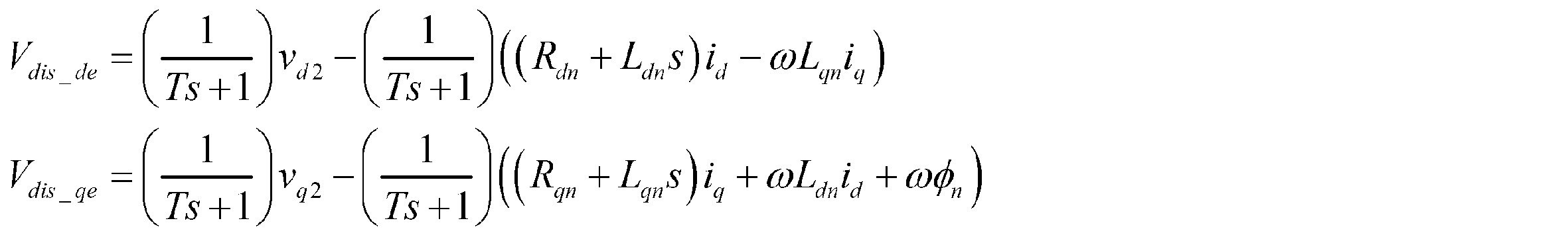
 実機上のチューニングで、特定の操舵条件によって外乱推定オブザーバの補償値を増減させたい場合がある。追従性が必要な場合は感応ゲインを大きくし、手感が重要となる保舵時は感応ゲインを下げたい場合などがあり、本発明では図8に示すような特性で、モータ回転数rpmに応じて感応ゲイン部605d及び605qの感応ゲインGd及びGqを可変する。感応ゲインGd及びGqは、モータ回転数rpmを入力とした1次関数(図8の特性A)やテーブル(図8の特性B)にすることができる。よって、dq軸外乱補償値Vcmp_d及びVcmp_qは、下記数5に従って出力される。推定された外乱はノイズなどの影響により、一時的に大きな値となる場合がある。そのままの値を外乱補償値とした場合、過補償となり制御系が不安定になる可能性がある。そのため、感応ゲイン部605d及び605qの後段にそれぞれ補償量制限部604d及び604qを設け、上限値を超えた推定外乱はイレギュラーな外乱とみなし、制限をかけた値を補償値としている。
Figure JPOXMLDOC01-appb-M000004

When tuning on an actual machine, you may want to increase or decrease the compensation value of the disturbance estimation observer according to specific steering conditions. There is a case where it is desired to increase the sensitivity gain when followability is required, and to decrease the sensitivity gain when steering is important. In the present invention, the characteristics shown in FIG. The sensitivity gains Gd and Gq of the sensitivity gain units 605d and 605q are varied. The sensitive gains Gd and Gq can be a linear function (characteristic A in FIG. 8) or a table (characteristic B in FIG. 8) with the motor rotation speed rpm as an input. Therefore, the dq-axis disturbance compensation values Vcmp_d and Vcmp_q are output according to the following formula 5. The estimated disturbance may be temporarily large due to the influence of noise or the like. If the value as it is is used as a disturbance compensation value, overcompensation may occur and the control system may become unstable. Therefore, compensation amount limiting units 604d and 604q are provided in the subsequent stages of the sensitive gain units 605d and 605q, respectively, and the estimated disturbance exceeding the upper limit value is regarded as irregular disturbance, and the limited value is used as the compensation value.
 図9は補償量制限部604dの特性例を示しているが、本例では上限値を+6[V]とし、下限値を-6[V]としているが、上限値は+6~+10[V]の範囲、下限値は-6~-10[V]の範囲が可能である。また、補償量制限部604qは補償量制限部604dと同一若しくは近似の特性である。 FIG. 9 shows a characteristic example of the compensation amount limiting unit 604d. In this example, the upper limit value is +6 [V] and the lower limit value is −6 [V], but the upper limit value is +6 to +10 [V]. The lower limit and the lower limit of −6 to −10 [V] are possible. The compensation amount limiting unit 604q has the same or approximate characteristics as the compensation amount limiting unit 604d.
Figure JPOXMLDOC01-appb-M000005
 
 図7に示すように、dq軸の制御系にはデッドタイム補償部200からデッドタイム補償値vd *及びvq *が加算されており、外乱推定オブザーバ600d及び600qでは、デッドタイムを除いた外乱又はデッドタイム補償で補償しきれない外乱(デッドタイム補償モデルの設計値とECUの個体差など、回路定数、モータ特性のバラツキ、経年変化、温度変化等による外乱)を推定できる。デッドタイムを除く外乱は下記数6となり、本機能で推定される外乱は数6の外乱に対する推定値となる。数6において、V* dis_dはデッドタイム補償適用時のd軸外乱電圧であり、V* dis_qはデッドタイム補償適用時のq軸外乱電圧である。
Figure JPOXMLDOC01-appb-M000005

As shown in FIG. 7, dead time compensation values v d * and v q * are added from the dead time compensation unit 200 to the dq axis control system, and the dead time is excluded in the disturbance estimation observers 600d and 600q. Disturbances or disturbances that cannot be compensated by dead time compensation (disturbances due to variations in circuit constants, motor characteristics, aging, temperature changes, etc., such as the design value of the dead time compensation model and individual differences between ECUs) can be estimated. Disturbances excluding dead time are given by the following equation 6, and the disturbance estimated by this function is an estimated value for the disturbance of equation 6. In Equation 6, V * dis_d is a d-axis disturbance voltage when dead time compensation is applied, and V * dis_q is a q-axis disturbance voltage when dead time compensation is applied.
Figure JPOXMLDOC01-appb-M000006
 
 次に、デッドタイム補償部200について説明する。デッドタイム補償部200には幾つかの実施例があり、図10の第1実施例(デッドタイム補償部200A)は、補償符号・補償量が自動計算されるため、オンセンター付近の低負荷・低速操舵状態においてもチャタリングなく、デッドタイム補償できる特長がある。
Figure JPOXMLDOC01-appb-M000006

Next, the dead time compensation unit 200 will be described. The dead time compensation unit 200 has several embodiments, and the first embodiment (dead time compensation unit 200A) in FIG. 10 automatically calculates the compensation code and the compensation amount. There is a feature that can compensate for dead time without chattering even in a low-speed steering state.
 デッドタイム補償部200Aは図10に示すように、減算部201(201U、201V、201W)及び202、中点電圧推定部210、3相指令電圧演算部204、電圧検出遅れモデル205、ゲイン部206、補償量制限部250及び3相交流/dq軸変換部203で構成されている。 As shown in FIG. 10, the dead time compensation unit 200A includes subtraction units 201 (201U, 201V, 201W) and 202, a midpoint voltage estimation unit 210, a three-phase command voltage calculation unit 204, a voltage detection delay model 205, and a gain unit 206. , A compensation amount limiting unit 250 and a three-phase AC / dq axis conversion unit 203.
 その詳細構成は図11であり、モータ回転角θは中点電圧推定部210及び3相交流/dq軸変換部203に入力され、モータ角速度ωは中点電圧推定部210に入力される。モータ端子電圧Vu,Vv,VwはLPF163U~163Wを経て中点電圧推定部210及び減算部201(201U, 201V, 201W)に入力されている。また、PWM制御部160内のDuty指令値演算部(図示せず)からのDuty値Dutyu,Dutyv,Dutywは3相指令電圧演算部204に入力され、インバータ印加電圧VRは中点電圧推定部210、3相指令電圧演算部204及び補償量制限部250に入力されている。なお、3相の信号線で図示すると煩雑になるため、図10及び図11では1相分のみを実線で示し、数字の“3”と斜線で3相であることを示している。以下で述べる他の実施例についても同様である。 The detailed configuration is shown in FIG. 11. The motor rotation angle θ is input to the midpoint voltage estimation unit 210 and the three-phase AC / dq axis conversion unit 203, and the motor angular velocity ω is input to the midpoint voltage estimation unit 210. The motor terminal voltages Vu, Vv, Vw are input to the midpoint voltage estimation unit 210 and the subtraction unit 201 (201U, 201V, 201W) via LPFs 163U to 163W. The duty values Duty u , Duty v , and Duty w from the duty command value calculation unit (not shown) in the PWM control unit 160 are input to the three-phase command voltage calculation unit 204, and the inverter applied voltage VR is the midpoint voltage. The signals are input to the estimation unit 210, the three-phase command voltage calculation unit 204, and the compensation amount restriction unit 250. 10 and 11 show only one phase with a solid line, and the numeral “3” and hatched lines indicate three phases. The same applies to other embodiments described below.
 中点電圧推定部210は、中点電圧の基準電圧をインバータ印加電圧VRにより算出する。詳細は図12の構成であり、ハードの構成、検出誤差などの影響により中点電圧はズレを生じるため、インバータ印加電圧VRと3相モータ端子電圧Vu~Vwの差分から補正する。補正するタイミングは、特定のモータ回転角θ及び特定のモータ角速度ωの条件で補正する。 The midpoint voltage estimation unit 210 calculates a reference voltage of the midpoint voltage based on the inverter applied voltage VR. The details are the configuration of FIG. 12, and since the midpoint voltage is shifted due to the influence of the hardware configuration, detection error, etc., it is corrected from the difference between the inverter applied voltage VR and the three-phase motor terminal voltages Vu to Vw. The correction timing is corrected under conditions of a specific motor rotation angle θ and a specific motor angular velocity ω.
 即ち、インバータ印加電圧VRは半減部211で半減(VR/2)され、半減値(VR/2)が減算部217及び218に加算入力される。端子電圧Vu~Vwは加算部216に入力されて加算され、加算結果(Vu+Vv+Vw)が除算部(1/3)212で1/3倍され、1/3倍された電圧“(Vu+Vv+Vw)/3”が減算部217に減算入力される。減算部217は半減値VR/2から電圧“(Vu+Vv+Vw)/3”を減算し、減算結果VRnaを補正値保持部214に入力する。補正タイミング判定部213は、モータ回転角θ及びモータ角速度ωに基づいて補正タイミングを判定し、補正信号CTを補正値保持部214に入力する。補正値保持部214で保持された電圧VRnbに基づき、補正量制限部215は電圧補正値ΔVmを算出する。 That is, the inverter applied voltage VR is halved (VR / 2) by the half part 211, and the half value (VR / 2) is added and inputted to the subtracting parts 217 and 218. The terminal voltages Vu to Vw are input to the adding unit 216 and added, and the addition result (Vu + Vv + Vw) is multiplied by 1/3 by the dividing unit (1/3) 212 and is multiplied by 1/3 to “(Vu + Vv + Vw) / 3 "Is inputted to the subtraction unit 217 by subtraction. The subtraction unit 217 subtracts the voltage “(Vu + Vv + Vw) / 3” from the half value VR / 2, and inputs the subtraction result VRna to the correction value holding unit 214. The correction timing determination unit 213 determines the correction timing based on the motor rotation angle θ and the motor angular velocity ω, and inputs the correction signal CT to the correction value holding unit 214. Based on the voltage VRnb held by the correction value holding unit 214, the correction amount limiting unit 215 calculates a voltage correction value ΔVm.
 補正タイミング判定部213及び補正値保持部214の詳細は図13に示す構成であり、補正タイミング判定部213は角度判定部213-1、有効回転数判定部213-2及びAND回路213-3で構成され、補正値保持部214は切換部214-1及び保持ユニット(Z-1)214-2で構成されている。 Details of the correction timing determination unit 213 and the correction value holding unit 214 are shown in FIG. 13, and the correction timing determination unit 213 includes an angle determination unit 213-1, an effective rotation number determination unit 213-2, and an AND circuit 213-3. The correction value holding unit 214 includes a switching unit 214-1 and a holding unit (Z −1 ) 214-2.
 即ち、モータ回転角θは角度判定部213-1に入力され、下記数7の判定が行われる。数7が成立するとき、角度判定部213-1は判定信号JD1を出力する。
(数7)
179[deg]<θ<180[deg]
 
 中点補正値の演算において上記数7のタイミングを補正条件とした場合、ゼロクロスポイントの電圧値を正確にサンプリングできる。このポイント以外では、モータ端子電圧に3次高調波が重畳されており、より正確な値が検出できない。例えば数7の条件で検出された各端子電圧をVu=6.83[V]、Vv=7.55[V]、Vw=5.94[V]、モータ印加電圧を13.52[V]とすると、(Vu+Vv+Vw)/3=6.77[V]、VR/2=6.76[V]となり、VR/2≒(Vu+Vv+Vw)/3となり、中点電圧に近い値となる。また、モータ角速度ωが大きい場合、モータ逆起電圧の影響が大きくなるのとサンプリングの精度が悪化するため、正確な補正演算ができなくなる。このため、有効回転数判定部213-2はモータ角速度ωが補正演算可能な有効角速度ω以下であるかを下記数8で判定し、モータ角速度ωが補正演算可能な有効角速度ω以下の時に、判定信号JD2を出力する。
(数8)
ω≦ω
 
 判定信号JD1及びJD2はAND回路213-3に入力され、判定信号JD1及びJD2が入力されたAND条件で補正信号CTが出力される。補正信号CTは補正値保持部214内の切換部214-1に切換信号として入力され、接点a, bを切り換える。接点aには減算結果VRnaが入力され、接点bには出力電圧VRnbが保持ユニット(Z-1)214-2を経て入力されている。補正値保持部214は次のタイミングまで安定した補正値を出力するため、値を保持する。また、補正量制限部215は、ノイズや逆起電圧、補正タイミング誤判定などにより、補正量が通常よりも明らかに大きい場合、当該補正量が正しくないと判断して最大補正量に制限する。最大補正量に制限された電圧補正値ΔVmは減算部218に入力され、減算部218で下記数9に基づいて演算された中点電圧推定値Vmが出力される。中点電圧推定値Vmは、減算部201(201U,201V,201W)にそれぞれ減算入力される。
That is, the motor rotation angle θ is input to the angle determination unit 213-1, and the determination of the following Expression 7 is performed. When Equation 7 holds, angle determination unit 213-1 outputs determination signal JD1.
(Equation 7)
179 [deg] <θ <180 [deg]

In the calculation of the midpoint correction value, when the timing of Equation 7 is used as the correction condition, the voltage value of the zero cross point can be accurately sampled. Except for this point, the third harmonic is superimposed on the motor terminal voltage, and a more accurate value cannot be detected. For example, if each terminal voltage detected under the condition of Equation 7 is Vu = 6.83 [V], Vv = 7.55 [V], Vw = 5.94 [V], and the motor applied voltage is 13.52 [V], (Vu + Vv + Vw) /3=6.77 [V], VR / 2 = 6.76 [V], and VR / 2≈ (Vu + Vv + Vw) / 3, which is close to the midpoint voltage. Further, when the motor angular velocity ω is large, if the influence of the motor back electromotive voltage is increased, the accuracy of sampling is deteriorated, so that an accurate correction calculation cannot be performed. Thus, the effective rotational speed determining portion 213-2 determines whether the motor angular speed omega is the correction operation can be effective angular velocity omega 0 or less by the following Expression 8, the motor angular velocity omega correction calculation can enable angular velocity omega 0 following Sometimes the decision signal JD2 is output.
(Equation 8)
ω ≦ ω 0

The determination signals JD1 and JD2 are input to the AND circuit 213-3, and the correction signal CT is output under the AND condition where the determination signals JD1 and JD2 are input. The correction signal CT is input as a switching signal to the switching unit 214-1 in the correction value holding unit 214, and switches the contacts a and b. The subtraction result VRna is input to the contact a, and the output voltage VRnb is input to the contact b via the holding unit (Z −1 ) 214-2. The correction value holding unit 214 holds a value in order to output a stable correction value until the next timing. If the correction amount is clearly larger than normal due to noise, back electromotive voltage, correction timing misjudgment, or the like, the correction amount limiting unit 215 determines that the correction amount is not correct and limits the correction amount to the maximum correction amount. The voltage correction value ΔVm limited to the maximum correction amount is input to the subtraction unit 218, and the midpoint voltage estimated value Vm calculated by the subtraction unit 218 based on the following equation 9 is output. The midpoint voltage estimated value Vm is subtracted and input to the subtraction unit 201 (201U, 201V, 201W).
Figure JPOXMLDOC01-appb-M000007
 
 また、3相指令電圧演算部204には3相Duty指令値Dutyu,Dutyv,Dutyw及びインバータ印加電圧VRが入力されており、3相指令電圧演算部204は、3相Duty指令値Dutyu,Dutyv,Dutyw及びインバータ印加電圧VRにより、下記数10を用いて3相指令電圧Vinを算出する。3相指令電圧Vinは、電圧検出遅れモデル205に入力される。なお、数10中のDutyrefは、Dutyu,Dutyv,Dutywを示し、Duty50%はDutyが50%であることを示し、Duty100%はDutyが100%であることを示している。
Figure JPOXMLDOC01-appb-M000007

Further, the three-phase command voltage calculation unit 204 is inputted with the three-phase duty command values Duty u , Duty v , Duty w and the inverter applied voltage VR, and the three-phase command voltage calculation unit 204 has the three-phase duty command value Duty. Based on u 1 , Duty v , Duty w and the inverter applied voltage VR, the three-phase command voltage Vin is calculated using the following formula 10. The three-phase command voltage Vin is input to the voltage detection delay model 205. In addition, Duty ref in Formula 10 indicates Duty u , Duty v , and Duty w , Duty 50% indicates that Duty is 50%, and Duty 100% indicates that Duty is 100%. .
Figure JPOXMLDOC01-appb-M000008
 
 中点電圧推定値Vmは減算部201(201u,201v,201w)に減算入力され、減算部201(201u,201v,201w)にはLPF163U,163V,163Wを経た端子電圧Vu,Vv,Vwが加算入力されている。減算部201u,201v,201wは、それぞれ3相端子電圧Vu,Vv,Vwから中点電圧推定値Vmを下記数11に従って減算する。これにより、3相検出電圧Vdn(Vdu,Vdv,Vdw)を演算する。3相検出電圧Vdn(Vdu,Vdv,Vdw)は、3相損失電圧演算部としての減算部202に入力される。
Figure JPOXMLDOC01-appb-M000008

The midpoint voltage estimated value Vm is subtracted and input to the subtraction unit 201 (201u, 201v, 201w), and the terminal voltages Vu, Vv, Vw that have passed through the LPFs 163U, 163V, 163W are added to the subtraction unit 201 (201u, 201v, 201w). Have been entered. The subtraction units 201u, 201v, and 201w subtract the midpoint voltage estimated value Vm from the three-phase terminal voltages Vu, Vv, and Vw according to the following equation 11, respectively. Thereby, the three-phase detection voltage Vdn (Vdu, Vdv, Vdw) is calculated. The three-phase detection voltage Vdn (Vdu, Vdv, Vdw) is input to the subtraction unit 202 as a three-phase loss voltage calculation unit.
Figure JPOXMLDOC01-appb-M000009
 
 端子電圧Vu~Vwの検出は、ECUのノイズフィルタ等により遅れが生じる。このため、直接3相指令電圧Vinと3相検出電圧Vdnの差分をとって損失電圧を算出した場合、位相差により誤差が生じる。この問題を解決するため、本実施例では、フィルタ回路等のハードウェアの検出遅れを1次のフィルタモデルとして近似し、位相差を改善する。本実施例の電圧検出遅れモデル205は、Tをフィルタ時定数として、下記数12の1次フィルタとしている。電圧検出遅れモデル205は、2次以上のフィルタをモデルとした構成でもよい。
Figure JPOXMLDOC01-appb-M000009

Detection of the terminal voltages Vu to Vw is delayed by an ECU noise filter or the like. For this reason, when the loss voltage is calculated by directly taking the difference between the three-phase command voltage Vin and the three-phase detection voltage Vdn, an error occurs due to the phase difference. In order to solve this problem, in this embodiment, the detection delay of hardware such as a filter circuit is approximated as a first-order filter model to improve the phase difference. The voltage detection delay model 205 of the present embodiment is a first-order filter of the following formula 12, where T is a filter time constant. The voltage detection delay model 205 may be configured using a second or higher order filter as a model.
Figure JPOXMLDOC01-appb-M000010
 
 減算部202には、電圧検出遅れモデル205からの3相補正指令電圧Vinpが加算入力され、減算部201からの3相検出電圧Vdnが減算入力されており、3相補正指令電圧Vinpから3相検出電圧Vdnを減算することにより、3相損失電圧PLA(Vloss_n)が算出される。即ち、減算部202で下記数13が演算される。
Figure JPOXMLDOC01-appb-M000010

The subtraction unit 202 is added with the three-phase correction command voltage Vinp from the voltage detection delay model 205, and is subtracted with the three-phase detection command voltage Vdn from the subtraction unit 201. By subtracting the detection voltage Vdn, the three-phase loss voltage PLA (Vloss_n) is calculated. That is, the following equation 13 is calculated by the subtracting unit 202.
Figure JPOXMLDOC01-appb-M000011
 
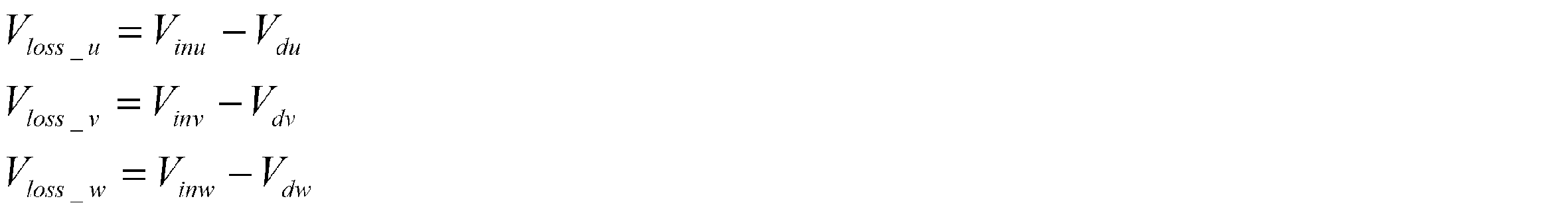
 3相損失電圧PLA(Vloss_n)はゲイン部206でゲインPG(例えば0.8)を乗算され、ゲインPGを乗算された3相損失電圧PLBは補償量制限部250に入力される。ゲインPGは基本的に調整する必要はないが、他の補償器との整合や実車チューニング、ECUの部品が変わったときなど、出力調整を必要とする場合には変更する。
Figure JPOXMLDOC01-appb-M000011

The three-phase loss voltage PLA (Vloss_n) is multiplied by a gain P G (for example, 0.8) by the gain unit 206, and the three-phase loss voltage PLB multiplied by the gain P G is input to the compensation amount limiting unit 250. Although the gain P G need not be essentially adjusted, alignment and vehicle tuning and other compensators, such as the components of the ECU are changed, the change in case of requiring output adjustment.
 補償量制限部250はインバータ印加電圧VRに感応しており、その詳細構成は図14のようになっている。即ち、インバータ印加電圧VRは、補償量制限部250内の補償量上下限値演算部251に入力され、図15に示すような特性で補償量制限値DTCaが演算される。即ち、補償量制限値DTCaは、インバータ印加電圧VRの所定電圧VR1まで一定制限値DTCa1であり、所定電圧VR1から所定電圧VR2(>VR1)まで線形(若しくは非線形)に増加し、所定電圧VR2以上で一定制限値DTCa2を保持する特性である。補償量制限値DTCaは切換部252の接点a1及び比較部255に入力されると共に、反転部254に入力される。また、3相損失電圧PLB(Vloss_u,Vloss_v,Vloss_w)は比較部255及び256に入力されると共に、切換部252の接点b1に入力されている。そして、反転部254の出力“-DTCa”は切換部253の接点a2に入力されている。切換部252の接点a1及びb1は、比較部255の比較結果CP1に基づいて切り換えられ、切換部253の接点a2及びb2は、比較部256の比較結果CP2に基づいて切り換えられる。 The compensation amount limiting unit 250 is sensitive to the inverter applied voltage VR, and its detailed configuration is as shown in FIG. That is, the inverter applied voltage VR is input to the compensation amount upper / lower limit value calculating unit 251 in the compensation amount limiting unit 250, and the compensation amount limit value DTCa is calculated with the characteristics shown in FIG. That is, the compensation amount limit value DTCa is a constant limit value DTCa1 up to the predetermined voltage VR1 of the inverter applied voltage VR, increases linearly (or nonlinearly) from the predetermined voltage VR1 to the predetermined voltage VR2 (> VR1), and exceeds the predetermined voltage VR2. This is a characteristic that holds the constant limit value DTCa2. The compensation amount limit value DTCa is input to the contact point a1 and the comparison unit 255 of the switching unit 252, and is also input to the inversion unit 254. The three-phase loss voltage PLB (Vloss_u, Vloss_v, Vloss_w) is input to the comparison units 255 and 256 and also to the contact b1 of the switching unit 252. The output “−DTCa” of the inverting unit 254 is input to the contact point a2 of the switching unit 253. The contacts a1 and b1 of the switching unit 252 are switched based on the comparison result CP1 of the comparison unit 255, and the contacts a2 and b2 of the switching unit 253 are switched based on the comparison result CP2 of the comparison unit 256.
 比較部255は補償量制限値DTCaと3相損失電圧PLBとを比較し、下記数14に従って切換部252の接点a1及びb1を切り換える。また、比較部256は補償量制限値-DTCaと3相損失電圧PLBとを比較し、下記数15に従って切換部253の接点a2及びb2を切り換える。
(数14)
  3相損失電圧PLB≧補償量上限値:(DTCa)のとき、切換部252の接点a1がON(切換部253の接点b2=DTCa)
  3相損失電圧PLB<補償量上限値:(DTCa)のとき、切換部252の接点b1がON(切換部253の接点b2=3相損失電圧PLB)
(数15)
  3相損失電圧PLB≦補償量下限値: (-DTCa)のとき、切換部253の接点a2がON(デッドタイム補償値DTC=-DTCa)
  3相損失電圧PLB>補償量下限値:(-DTCa)のとき、切換部253の接点b2がON(デッドタイム補償値DTC=切換部252の出力)
 
 次に、デッドタイム補償部200における第2実施例である図16について、図10に対応させて説明する。図16の第2実施例(デッドタイム補償部200B)は、角度と相電流の位相が合う低速・中速操舵領域においても補償精度が高い特長がある。
The comparison unit 255 compares the compensation amount limit value DTCa with the three-phase loss voltage PLB, and switches the contacts a1 and b1 of the switching unit 252 according to the following equation (14). The comparison unit 256 compares the compensation amount limit value -DTCa with the three-phase loss voltage PLB, and switches the contacts a2 and b2 of the switching unit 253 according to the following formula 15.
(Equation 14)
When 3-phase loss voltage PLB ≧ compensation amount upper limit value: (DTCa), contact a1 of switching unit 252 is ON (contact b2 of switching unit 253 = DTCa).
When 3-phase loss voltage PLB <compensation amount upper limit: (DTCa), contact b1 of switching unit 252 is ON (contact b2 of switching unit 253 = 3-phase loss voltage PLB)
(Equation 15)
Three-phase loss voltage PLB ≤ compensation lower limit: When (-DTCa), contact a2 of switching section 253 is ON (dead time compensation value DTC = -DTCa)
When three-phase loss voltage PLB> compensation amount lower limit: (−DTCa), contact b2 of switching unit 253 is ON (dead time compensation value DTC = output of switching unit 252)

Next, FIG. 16 as a second embodiment of the dead time compensation unit 200 will be described with reference to FIG. The second embodiment (dead time compensation unit 200B) of FIG. 16 has a feature that the compensation accuracy is high even in the low-speed / medium-speed steering region in which the phase of the angle and the phase current match.
 本実施例のデッドタイム補償部200Bには、図2の操舵補助指令値Iref2に相当するq軸の操舵補助指令値iqrefが入力されると共に、モータ回転角θ及びモータ角速度ωが入力されている。デッドタイム補償部200Bは、電流制御遅れモデル208、補償符号推定部209、乗算部232、233d及び233q、加算部221、位相調整部207、インバータ印加電圧感応ゲイン部220、角度-デッドタイム(DT)補償値関数部230U、230V及び230W、乗算部231U、231V及び231W、3相交流/dq軸変換部203、電流指令値感応ゲイン部240で構成されている。 The dead time compensator 200B of the present embodiment receives a q-axis steering assist command value i qref corresponding to the steering assist command value Iref2 of FIG. 2, and also receives a motor rotation angle θ and a motor angular velocity ω. Yes. The dead time compensation unit 200B includes a current control delay model 208, a compensation code estimation unit 209, multiplication units 232, 233d and 233q, an addition unit 221, a phase adjustment unit 207, an inverter applied voltage sensitive gain unit 220, an angle-dead time (DT ) Compensation value function units 230U, 230V and 230W, multiplication units 231U, 231V and 231W, a three-phase AC / dq axis conversion unit 203, and a current command value sensitive gain unit 240.
 デッドタイム補償部200Bの詳細構成は図17であり、q軸操舵補助指令値iqrefは、電流制御遅れモデル208に入力される。dq軸の電流指令値id *及びiq *が実電流に反映されるまでに、ECUのノイズフィルタ等により遅れが生じる。このため、直接電流指令値iq *から符号を判定しようとすると、タイミングずれが生じる場合がある。この問題を解決するため、電流制御全体の遅れを1次のフィルタモデルとして近似し、位相差を改善する。本実施例の電流制御遅れモデル208は、Tをフィルタ時定数として、下記数16の1次フィルタとしている。 The detailed configuration of the dead time compensation unit 200B is shown in FIG. 17, and the q-axis steering assist command value i qref is input to the current control delay model 208. There is a delay due to the noise filter or the like of the ECU before the dq axis current command values i d * and i q * are reflected in the actual current. For this reason, a timing shift may occur when trying to determine the sign directly from the current command value i q * . In order to solve this problem, the delay of the entire current control is approximated as a first-order filter model to improve the phase difference. The current control delay model 208 of the present embodiment is a first-order filter of the following formula 16, where T is a filter time constant.
Figure JPOXMLDOC01-appb-M000012
 
 電流制御遅れモデル208から出力される電流指令値Icmは、電流指令値感応ゲイン部240及び補償符号推定部209に入力される。低電流領域においてデッドタイム補償量が過補償になる場合があり、電流指令値感応ゲイン部240は、電流指令値Icm(操舵補助指令値iqref)の大きさにより補償量を下げるゲインを算出する機能を持っている。また、電流指令値Icm(操舵補助指令値iqref)からのノイズなどで、補償量を下げるゲインが振動しないように、加重平均フィルタを使用してノイズの低減処理を行っている。
Figure JPOXMLDOC01-appb-M000012

The current command value Icm output from the current control delay model 208 is input to the current command value sensitive gain unit 240 and the compensation code estimation unit 209. The dead time compensation amount may be overcompensated in the low current region, and the current command value sensitive gain unit 240 calculates a gain that lowers the compensation amount according to the magnitude of the current command value Icm (steering assist command value i qref ). Has function. Further, a noise reduction process is performed using a weighted average filter so that the gain that lowers the compensation amount does not vibrate due to noise from the current command value Icm (steering assist command value i qref ).
 電流指令値感応ゲイン部240は図18に示すような構成であり、電流指令値Icmは絶対値部241で絶対値|Icm|とされる。絶対値|Icm|は入力制限部242で最大値を制限され、最大値を制限された絶対値の電流指令値がスケール変換部243を経て加重平均フィルタ244に入力される。加重平均フィルタ244でノイズを低減された電流指令値Iamは、減算部245に加算入力され、減算部245で所定のオフセットOSを減算される。オフセットOSを減算する理由は、微小電流指令値によるチャタリング防止のためであり、オフセットOS以下の入力値を最小のゲインに固定する。オフセットOSは一定値である。減算部245でオフセットOSを減算された電流指令値Iasはゲイン部246に入力され、図19に示すようなゲイン特性に従って電流指令値感応ゲインGcを出力する。即ち、ゲイン部246における電流指令値感応ゲインGcの初期値はGca1であり、その後電流指令値Iasの所定値Ias1まで線形に増加し、所定値Ias1を超えると一定値Gca2を保持する。 The current command value sensitive gain unit 240 is configured as shown in FIG. 18, and the current command value Icm is set to an absolute value | Icm | by the absolute value unit 241. The absolute value | Icm | is limited to a maximum value by the input limiting unit 242, and an absolute current command value whose maximum value is limited is input to the weighted average filter 244 via the scale conversion unit 243. The current command value Iam whose noise has been reduced by the weighted average filter 244 is added to the subtraction unit 245, and a predetermined offset OS is subtracted by the subtraction unit 245. The reason for subtracting the offset OS is to prevent chattering due to the minute current command value, and the input value below the offset OS is fixed to the minimum gain. The offset OS is a constant value. The current command value Ias obtained by subtracting the offset OS by the subtracting unit 245 is input to the gain unit 246, and a current command value sensitive gain Gc is output according to the gain characteristics as shown in FIG. That is, the initial value of the current command value sensitive gain Gc in the gain unit 246 is Gca1, and then increases linearly to the predetermined value Ias1 of the current command value Ias, and when the predetermined value Ias1 is exceeded, the constant value Gca2 is held.
 また、電流指令値感応ゲイン部240から出力される電流指令値感応ゲインGcは、入力される電流指令値Icmに対して例えば図20に示すような特性である。即ち、所定電流Icm1まで一定ゲインGcc1であり、所定電流Icm1から所定電流Icm2(>Icm1)まで線形(若しくは非線形)に増加し、所定電流Icm2以上で一定ゲインGcc2を保持する特性である。 Further, the current command value sensitive gain Gc output from the current command value sensitive gain unit 240 has a characteristic as shown in FIG. 20, for example, with respect to the input current command value Icm. That is, the gain is constant gain Gcc1 up to a predetermined current Icm1, increases linearly (or nonlinearly) from the predetermined current Icm1 to the predetermined current Icm2 (> Icm1), and maintains the constant gain Gcc2 above the predetermined current Icm2.
 補償符号推定部209は入力される電流指令値Icmに対して、図21(A)及び(B)に示すヒステリシス特性で正(+1)又は負(-1)の補償符号SNを出力する。電流指令値Icmがゼロクロスするポイントを基準として補償符号SNを推定するが、チャタリング抑制のためにヒステリシス特性となっている。推定された補償符号SNは乗算部232に入力される。単純に相電流指令値モデルの電流符号からデッドタイム補償値の符号を決めた場合、低負荷においてチャタリングが発生する。オンセンターで軽く左右にハンドルを切った時に、トルクリップルが発生する。この問題を改善するために符号判定にヒステリシスを設け、設定した電流値を超えて符号が変化した場合以外、現在の符号を保持してチャタリングを抑制する。 The compensation code estimation unit 209 outputs a positive (+1) or negative (−1) compensation code SN with hysteresis characteristics shown in FIGS. 21A and 21B with respect to the input current command value Icm. The compensation code SN is estimated based on the point where the current command value Icm crosses zero, but has hysteresis characteristics to suppress chattering. The estimated compensation code SN is input to the multiplier 232. When the sign of the dead time compensation value is simply determined from the current sign of the phase current command value model, chattering occurs at a low load. Torque ripple occurs when the handle is lightly turned left and right at the center. In order to improve this problem, a hysteresis is provided in the code determination, and the current code is held and chattering is suppressed except when the code changes beyond the set current value.
 電流指令値感応ゲイン部240からの電流指令値感応ゲインGcは乗算部232に入力され、乗算部232は補償符号SNを乗算した電流指令値感応ゲインGcs(=Gc×SN)を出力する。電流指令値感応ゲインGcsは、乗算部233d及び233qに入力される。 The current command value sensitive gain Gc from the current command value sensitive gain unit 240 is input to the multiplier 232, and the multiplier 232 outputs a current command value sensitive gain Gcs (= Gc × SN) multiplied by the compensation code SN. The current command value sensitive gain Gcs is input to the multipliers 233d and 233q.
 また、最適なデッドタイム補償量はインバータ印加電圧VRに応じて変化するので、本実施例ではインバータ印加電圧VRに応じた電圧感応ゲインGvを演算し、デッドタイム補償量を可変するようにしている。インバータ印加電圧VRを入力して電圧感応ゲインGvを出力するインバータ印加電圧感応ゲイン部220は図22に示す構成であり、インバータ印加電圧VRは入力制限部221で正負最大値を制限され、最大値を制限されたインバータ印加電圧VRnxはインバータ印加電圧/デッドタイム補償ゲイン変換テーブル222に入力される。インバータ印加電圧/デッドタイム補償ゲイン変換テーブル222の特性は、例えば図23に示すようになっている。即ち、所定電圧9.0[V]まで一定ゲインGv(=0.7)であり、所定電圧9.0[V]から所定電圧15.0[V]まで線形(若しくは非線形)に増加し、所定電圧15.0[V]以上で一定ゲインGv(=1.2)を保持する特性である。変曲点のインバータ印加電圧9.0[V]及び15.0[V]と、電圧感応ゲイン“0.7”及び“1.2”は一例であり、適宜変更可能である。演算された電圧感応ゲインGvは、乗算部231U,231V,231Wに入力される。 Also, since the optimum dead time compensation amount changes according to the inverter applied voltage VR, in this embodiment, the voltage sensitive gain Gv according to the inverter applied voltage VR is calculated to vary the dead time compensation amount. . The inverter applied voltage sensitive gain unit 220 that inputs the inverter applied voltage VR and outputs the voltage sensitive gain Gv is configured as shown in FIG. 22, and the inverter applied voltage VR is limited to the maximum value by the input restricting unit 221. Is applied to the inverter applied voltage / dead time compensation gain conversion table 222. The characteristics of the inverter applied voltage / dead time compensation gain conversion table 222 are as shown in FIG. 23, for example. That is, the constant gain Gv (= 0.7) up to the predetermined voltage 9.0 [V], increases linearly (or non-linearly) from the predetermined voltage 9.0 [V] to the predetermined voltage 15.0 [V], and above the predetermined voltage 15.0 [V]. This is a characteristic that maintains a constant gain Gv (= 1.2). The inverter applied voltages 9.0 [V] and 15.0 [V] at the inflection points and the voltage sensitive gains “0.7” and “1.2” are examples, and can be appropriately changed. The calculated voltage sensitive gain Gv is input to the multipliers 231U, 231V, and 231W.
 更に、モータ角速度ωによりデッドタイム補償のタイミングを早めたり、遅くしたい場合、モータ角速度ωに応じて調整角度を算出する機能のために位相調整部207を有している。位相調整部207は、進角制御の場合は図24に示すような特性であり、算出された位相調整角Δθは加算部221に入力され、検出されたモータ回転角θと加算される。加算部221の加算結果であるモータ回転角θm(=θ+Δθ)は、角度-デッドタイム(DT)償値関数部230U,230V,230Wに入力されると共に、3相交流/dq軸変換部203に入力される。 Furthermore, when the dead time compensation timing is advanced or delayed by the motor angular velocity ω, the phase adjustment unit 207 is provided for the function of calculating the adjustment angle according to the motor angular velocity ω. The phase adjustment unit 207 has characteristics as shown in FIG. 24 in the case of advance angle control, and the calculated phase adjustment angle Δθ is input to the addition unit 221 and added to the detected motor rotation angle θ. The motor rotation angle θm (= θ + Δθ) that is the addition result of the adder 221 is input to the angle-dead time (DT) compensation function units 230U, 230V, and 230W, and to the three-phase AC / dq axis converter 203 Entered.
 モータ電気角を検出してDuty指令値を演算してから、実際にPWM信号に反映されるまで数十~百[μs]の時間遅れがある。この間、モータが回転しているので、演算時のモータ電気角と反映時のモータ電気角とで位相ずれが発生する。この位相ずれを補償するため、モータ角速度ωに応じて進角を行い、位相を調整している。 ¡There is a delay of several tens to hundreds [μs] from when the motor electrical angle is detected and the duty command value is calculated until it is actually reflected in the PWM signal. During this time, since the motor is rotating, a phase shift occurs between the motor electrical angle at the time of calculation and the motor electrical angle at the time of reflection. In order to compensate for this phase shift, the phase is adjusted by advancing according to the motor angular velocity ω.
 角度-デッドタイム(DT)補償値関数部230U,230V,230Wは図25に詳細を示すように、位相調整されたモータ回転角θmに対して、電気角0~359[deg]の範囲で120[deg]ずつ位相のずれた矩形波の各相デッドタイム基準補償値Udt,Vdt,Wdtを出力する。デッドタイム補償値角度関数部230U,230V,230Wは、3相で必要とされるデッドタイム補償値を角度による関数とし、ECUの実時間上で計算し、3相のデッドタイム基準補償値Udt,Vdt,Wdtを出力する。デッドタイム基準補償値の角度関数は、ECUのデッドタイムの特性により異なる。 As shown in detail in FIG. 25, the angle-dead time (DT) compensation value function units 230U, 230V, and 230W are 120 in the electric angle range of 0 to 359 [deg] with respect to the phase-adjusted motor rotation angle θm. Each phase dead time reference compensation value Udt, Vdt, Wdt of a rectangular wave whose phase is shifted by [deg] is output. The dead time compensation value angle function unit 230U, 230V, 230W uses the dead time compensation value required in the three phases as a function of the angle, and calculates the ECU in real time to calculate the three phase dead time reference compensation value Udt, Outputs Vdt and Wdt. The angle function of the dead time reference compensation value differs depending on the dead time characteristic of the ECU.
 デッドタイム基準補償値Udt,Vdt,Wdtはそれぞれ乗算部231U,231V,231Wに入力され、電圧感応ゲインGvと乗算される。電圧感応ゲインGvを乗算された3相のデッドタイム補償値Udtc(=Gv・Udt),Vdtc(=Gv・Vdt),Wdtc(=Gv・Wdt)は3相交流/dq軸変換部203に入力される。3相交流/dq軸変換部203は、モータ回転角θmに同期して、3相のデッドタイム補償値Udtc,Vdtc,Wdtcを2相のdq軸のデッドタイム補償値vda *及びvqa *に変換する。デッドタイム補償値vda *及びvqa *はそれぞれ乗算部233d及び233qに入力され、電流指令値感応ゲインGcsと乗算される。乗算部233d及び233qにおける乗算結果がデッドタイム補償値vd *及びvq *であり、デッドタイム補償値vd *及びvq *はそれぞれ加算部123d及び123qで電圧指令値vd2及びvq2と加算される。 The dead time reference compensation values Udt, Vdt, and Wdt are input to the multipliers 231U, 231V, and 231W, respectively, and multiplied by the voltage sensitive gain Gv. The three-phase dead time compensation values Udtc (= Gv · Udt), Vdtc (= Gv · Vdt) and Wdtc (= Gv · Wdt) multiplied by the voltage sensitive gain Gv are input to the three-phase AC / dq axis converter 203 Is done. The three-phase AC / dq axis converter 203 synchronizes the three-phase dead time compensation values Udtc, Vdtc, and Wdtc with the two-phase dq axis dead time compensation values v da * and v qa * in synchronization with the motor rotation angle θm . Convert to The dead time compensation values v da * and v qa * are respectively input to the multipliers 233d and 233q, and are multiplied by the current command value sensitive gain Gcs. The multiplication results in the multipliers 233d and 233q are the dead time compensation values v d * and v q * , and the dead time compensation values v d * and v q * are added to the voltage command values vd2 and vq2 in the adders 123d and 123q, respectively. Is done.
 次に、デッドタイム補償部200における第3実施例である図26について、図10及び図16に対応させて説明する。図26の第3実施例(デッドタイム補償部200C)は、高速操舵時においても単純に補償を入れることができる特長がある。 Next, FIG. 26, which is a third embodiment of the dead time compensation unit 200, will be described with reference to FIGS. The third embodiment (dead time compensation unit 200C) of FIG. 26 has an advantage that compensation can be simply made even during high speed steering.
 デッドタイム補償部200Cは、加算部273、乗算部272、インバータ印加電圧感応補償量演算部260、3相電流指令値モデル270、相電流補償符号推定部271、位相調整部207、3相交流/dq軸変換部203で構成されている。モータ回転角θは加算部273に入力され、モータ角速度ωは位相調整部207に入力されている。また、インバータ印加電圧VRはインバータ印加電圧感応補償量演算部260に入力され、加算部273で算出された位相調整後のモータ回転角θmが3相電流指令値モデル270に入力されている。 The dead time compensation unit 200C includes an addition unit 273, a multiplication unit 272, an inverter applied voltage sensitive compensation amount calculation unit 260, a three-phase current command value model 270, a phase current compensation code estimation unit 271, a phase adjustment unit 207, a three-phase AC / The dq axis conversion unit 203 is configured. The motor rotation angle θ is input to the adding unit 273, and the motor angular velocity ω is input to the phase adjusting unit 207. Further, the inverter applied voltage VR is input to the inverter applied voltage sensitive compensation amount calculation unit 260, and the motor rotation angle θm after phase adjustment calculated by the adder 273 is input to the three-phase current command value model 270.
 モータ角速度ωによりデッドタイム補償タイミングを早めたり、遅くしたい場合、モータ角速度ωに応じて調整角度を算出する機能のために位相調整部207を有している。位相調整部207は、進角制御の場合は図24と同様な特性であり、算出された位相調整角Δθは加算部273に入力され、検出されたモータ回転角θと加算される。加算部273の加算結果である位相調整後のモータ回転角θm(=θ+Δθ)は、3相電流指令値モデル270に入力されると共に、3相交流/dq軸変換部203に入力される。位相調整部207を設ける理由は、第2実施例の場合と同様である。 When the dead time compensation timing is advanced or delayed by the motor angular velocity ω, the phase adjustment unit 207 is provided for the function of calculating the adjustment angle according to the motor angular velocity ω. The phase adjustment unit 207 has the same characteristics as those in FIG. 24 in the case of the advance angle control, and the calculated phase adjustment angle Δθ is input to the addition unit 273 and added to the detected motor rotation angle θ. The motor rotation angle θm (= θ + Δθ) after phase adjustment, which is the addition result of the adder 273, is input to the three-phase current command value model 270 and to the three-phase AC / dq axis converter 203. The reason for providing the phase adjustment unit 207 is the same as in the second embodiment.
 最適なデッドタイム補償量はインバータ印加電圧VRに応じて変化するので、本実施例でもインバータ印加電圧VRに応じたデッドタイム補償量DTCを演算し、可変するようにしている。インバータ印加電圧VRを入力してデッドタイム補償量DTCを出力するインバータ印加電圧感応補償量演算部260は図27に示す構成であり、インバータ印加電圧VRは入力制限部261で正負最大値を制限され、最大値を制限されたインバータ印加電圧VRmxはインバータ印加電圧/デッドタイム補償量変換テーブル262に入力される。 Since the optimum dead time compensation amount changes according to the inverter applied voltage VR, the dead time compensation amount DTC corresponding to the inverter applied voltage VR is also calculated and varied in this embodiment. The inverter applied voltage sensitive compensation amount calculation unit 260 that inputs the inverter applied voltage VR and outputs the dead time compensation amount DTC is configured as shown in FIG. 27, and the inverter applied voltage VR is limited by the input limiting unit 261 to the maximum value of positive and negative. The inverter application voltage VRmx whose maximum value is limited is input to the inverter application voltage / dead time compensation amount conversion table 262.
 インバータ印加電圧/デッドタイム補償量変換テーブル262の特性は、例えば図28のようになっている。即ち、最大値を制限されたインバータ印加電圧VRmxが所定インバータ印加電圧VR1まで一定のデッドタイム補償量DTC1であり、所定インバータ印加電圧VR1から所定インバータ印加電圧VR2(>VR1)まで線形(若しくは非線形)に増加し、所定インバータ印加電圧VR2以上で一定のデッドタイム補償量DTC2を出力する特性である。 The characteristics of the inverter applied voltage / dead time compensation amount conversion table 262 are, for example, as shown in FIG. That is, the inverter application voltage VRmx whose maximum value is limited is a constant dead time compensation amount DTC1 up to the predetermined inverter application voltage VR1, and is linear (or non-linear) from the predetermined inverter application voltage VR1 to the predetermined inverter application voltage VR2 (> VR1). This is a characteristic that outputs a constant dead time compensation amount DTC2 at a predetermined inverter applied voltage VR2 or higher.
 d軸電流指令値id *及びq軸電流指令値iq *はモータ回転角θmと共に、3相電流指令値モデル270に入力される。3相電流指令値モデル270は、dq軸電流指令値id *及びiq *、モータ回転角θmから、図29に示すような120[deg]ずつ位相のずれた正弦波の3相電流モデル指令値Icmaを演算若しくはテーブルにより算出する(下記数17~数18参照)。3相電流モデル指令値Icmaは、モータタイプによって相違している。d軸電流指令値iref_dとq軸電流指令値iref_qをモータ電気角θeから3相の電流指令値(U・V・W相)に変換すると、下記数17となる。 The d-axis current command value i d * and the q-axis current command value i q * are input to the three-phase current command value model 270 together with the motor rotation angle θm. The three-phase current command value model 270 is a sine wave three-phase current model whose phase is shifted by 120 [deg] as shown in FIG. 29 from the dq-axis current command values i d * and i q * and the motor rotation angle θm. The command value Icma is calculated or calculated by a table (see the following equations 17 to 18). The three-phase current model command value Icma differs depending on the motor type. When the d-axis current command value i ref_d and the q-axis current command value i ref_q are converted from the motor electrical angle θe to a three-phase current command value (U / V / W phase), the following Expression 17 is obtained.
Figure JPOXMLDOC01-appb-M000013
 
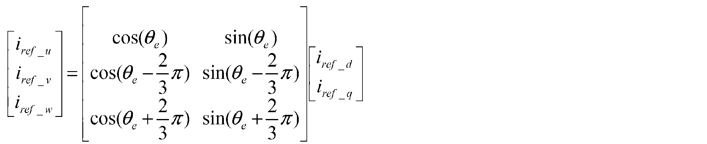
上記数17から各相電流指令値を求めると、U相電流指令値モデルiref_u、V相電流指令値モデルiref_v及びW相電流指令値モデルiref_wは、それぞれ下記数18で表わされる。
Figure JPOXMLDOC01-appb-M000013

When the respective phase current command values are obtained from the above equation 17, the U phase current command value model i ref_u , the V phase current command value model i ref_v and the W phase current command value model i ref_w are respectively expressed by the following equation 18.
Figure JPOXMLDOC01-appb-M000014
 
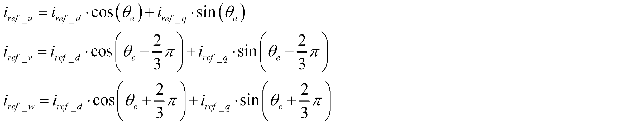
 テーブルは、EEPROM(Electrically Erasable and Programmable Read-Only Memory)に格納されているタイプでも、RAM(Random Access Memory)上に展開されているタイプでも良い。数18の使用において、sinθのみをテーブル化しておき、入力θを90°オフセットさせて使用することによりcosθを演算したり、120°オフセットさせるなどして、その他のsin関数項を演算しても良い。ROM容量に問題がなかったり、複雑な指令値モデル(例えば擬似矩形波モータなど)の場合は、数式全体をテーブル化しておく。
Figure JPOXMLDOC01-appb-M000014

The table may be a type stored in an EEPROM (Electrically Erasable and Programmable Read-Only Memory) or a type developed on a RAM (Random Access Memory). In the use of Equation 18, only sin θ e is tabulated and the input θ e is offset by 90 ° to calculate cos θ e or offset by 120 ° to calculate other sin function terms. You may do it. If there is no problem with the ROM capacity or a complicated command value model (for example, a pseudo-rectangular wave motor), the entire mathematical formula is tabulated.
 3相電流指令値モデル270からの3相電流モデル指令値Icmaは、相電流補償符号推定部271に入力される。相電流補償符号推定部271は入力される3相電流モデル指令値Icmaに対して、図21(A)及び(B)に示すようなヒステリシス特性で正(+1)又は負(-1)の補償符号SNを出力する。3相電流モデル指令値Icmaがゼロクロスするポイントを基準として補償符号SNを推定するが、チャタリング抑制のためにヒステリシス特性となっている。推定された補償符号SNは乗算部272に入力される。単純に相電流指令値モデルの電流符号からデッドタイム補償値の符号を決めた場合、低負荷においてチャタリングが発生する。例えば、オンセンターで軽く左右にハンドルを切った時に、トルクリップルが発生する。この問題を改善するために符号判定にヒステリシスを設け(図21では±0.25[A])、設定した電流値を超えて符号が変化した場合以外、現在の符号を保持してチャタリングを抑制する。 The three-phase current model command value Icma from the three-phase current command value model 270 is input to the phase current compensation code estimation unit 271. The phase current compensation code estimator 271 compensates positive (+1) or negative (−1) with hysteresis characteristics as shown in FIGS. 21A and 21B for the input three-phase current model command value Icma. The code SN is output. The compensation code SN is estimated based on the point where the three-phase current model command value Icma zero-crosses, but has hysteresis characteristics to suppress chattering. The estimated compensation code SN is input to the multiplier 272. When the sign of the dead time compensation value is simply determined from the current sign of the phase current command value model, chattering occurs at a low load. For example, torque ripple occurs when the handle is lightly turned left and right at the on-center. In order to remedy this problem, a hysteresis is provided in the code determination (± 0.25 [A] in FIG. 21), and the current code is retained and chattering is suppressed unless the code changes beyond the set current value.
 インバータ印加電圧感応補償量演算部260からのデッドタイム補償量DTCは乗算部272に入力され、乗算部272は補償符号SNを乗算したデッドタイム補償値DTCa(=DTC×SN)を出力する。デッドタイム補償値DTCaは3相交流/dq軸変換部203に入力され、3相交流/dq軸変換部203は、モータ回転角θmに同期して2相のデッドタイム補償値vd *及びvq *を出力する。デッドタイム補償値vd *及びvq *は、それぞれ加算部123d及び123qにおいて電圧指令値vd2及びvq2と加算され、インバータ161のデッドタイム補償が実施される。 The dead time compensation amount DTC from the inverter applied voltage sensitive compensation amount calculation unit 260 is input to the multiplication unit 272, and the multiplication unit 272 outputs a dead time compensation value DTCa (= DTC × SN) multiplied by the compensation code SN. The dead time compensation value DTCa is input to the three-phase AC / dq axis conversion unit 203, and the three-phase AC / dq axis conversion unit 203 synchronizes with the motor rotation angle θm to provide two-phase dead time compensation values v d * and v q * is output. The dead time compensation values v d * and v q * are added to the voltage command values vd2 and vq2 in the adders 123d and 123q, respectively, and the dead time compensation of the inverter 161 is performed.
 このように第3実施例では、dq軸電流指令値を3相の電流モデル指令値に変換すると共に、補償符号を推定し、インバータ印加電圧から演算されたインバータのデッドタイム補償量を演算し、推定された補償符号によるデッドタイム補償値をdq軸上の電圧指令値にフィードフォワード補償している。デッドタイムの補償符号については3相電流モデル指令値を使用し、デッドタイム補償量はインバータ印加電圧VRから算出し、電流指令値(id *,iq *)の大きさやインバータ印加電圧VRの大きさによって、補償値が最適な大きさと方向になるように可変となっている。 Thus, in the third embodiment, the dq-axis current command value is converted into a three-phase current model command value, the compensation code is estimated, the inverter dead time compensation amount calculated from the inverter applied voltage is calculated, The dead time compensation value based on the estimated compensation code is feedforward compensated to the voltage command value on the dq axis. For the dead time compensation code, the 3-phase current model command value is used, the dead time compensation amount is calculated from the inverter applied voltage VR, and the magnitude of the current command value (i d * , i q * ) and the inverter applied voltage VR Depending on the magnitude, the compensation value is variable so as to be in the optimum magnitude and direction.
 なお、デッドタイム補償部200の実施例を示す図10、図16、図26は、操舵条件に応じて切り換えて使用しても良いし、或いはどれか1つだけを使用しても良い。 In addition, FIG. 10, FIG. 16, FIG. 26 which shows the Example of the dead time compensation part 200 may be switched and used according to steering conditions, or may use only one.
 次に、空間ベクトル変調について説明する。本発明では演算回数の削減などのため、電圧の次元からDutyの次元に変換してから空間ベクトル変換演算を行っている。そして、空間ベクトル変調部300は図30に示すように、dq軸空間の2相Duty値(Duty指令値Duty_d **及びDuty_q **)を3相Duty値(Duty_u,Duty_v,Duty_w)に変換し、3相Duty値(Duty_u,Duty_v,Duty_w)に3次高調波を重畳して3相のDuty指令値Duty_u *,Duty_v*,Duty_w *を出力する機能を有していれば良く、例えば本出願人による特開2017-70066、WO/2017/098840等で提案している空間ベクトル変調の手法を用いても良い。 Next, space vector modulation will be described. In the present invention, in order to reduce the number of operations, the space vector conversion operation is performed after conversion from the voltage dimension to the Duty dimension. As space vector modulation section 300 shown in FIG. 30, two-phase Duty value of the dq-axis space (Duty command value Duty_ d ** and Duty_ q **) a 3-phase Duty value (Duty_u, Duty_v, Duty_w) to conversion, 3 phase Duty value (Duty_u, Duty_v, Duty_w) the third harmonic superimposed to have three-phase Duty command value Duty _u *, Duty _v *, have a function of outputting the Duty _w * For example, the space vector modulation technique proposed in Japanese Patent Application Laid-Open No. 2017-70066, WO / 2017/098840, etc. by the present applicant may be used.
 即ち、空間ベクトル変調を電圧の式で説明すると、空間ベクトル変調は、dq軸空間の電圧指令値Vd3及びVq3、モータ回転角θ及びセクター番号n(#1~#6)に基づいて、以下に示すような座標変換を行い、ブリッジ構成のインバータのFET(上側アームQ1、Q3、Q5、下側アームQ2、Q4、Q6)のON/OFFを制御する、セクター#1~#6に対応したスイッチングパターンS1~S6をモータに供給することによって、モータの回転を制御する機能を有する。座標変換については、空間ベクトル変調において、電圧指令値Vd3及びVq3は、数19に基づいて、α-β座標系における電圧ベクトルVα及びVβに座標変換が行われる。この座標変換に用いる座標軸及びモータ回転角θの関係については、図31に示す。 That is, the space vector modulation is described by the voltage equation. The space vector modulation is based on the voltage command values Vd3 and Vq3 of the dq axis space, the motor rotation angle θ, and the sector number n (# 1 to # 6) as follows. Switching corresponding to sectors # 1 to # 6 that controls the ON / OFF of FETs (upper arms Q1, Q3, Q5, lower arms Q2, Q4, Q6) of bridge inverters by performing coordinate conversion as shown By supplying the patterns S1 to S6 to the motor, it has a function of controlling the rotation of the motor. Regarding the coordinate conversion, in the space vector modulation, the voltage command values Vd3 and Vq3 are converted into voltage vectors Vα and Vβ in the α-β coordinate system based on the equation (19). The relationship between the coordinate axis used for this coordinate conversion and the motor rotation angle θ is shown in FIG.
Figure JPOXMLDOC01-appb-M000015
 
 なお、Duty指令値Duty_d,Duty_qと電圧指令値Vd3及びVq3との関係は、インバータ印加電圧をVRとして、下記数20で表わされる。
Figure JPOXMLDOC01-appb-M000015

The relationship between the Duty command values Duty_d and Duty_q and the voltage command values Vd3 and Vq3 is expressed by the following equation 20 where the inverter applied voltage is VR.
Figure JPOXMLDOC01-appb-M000016
 
そして、d-q座標系における目標電圧ベクトルとα-β座標系における目標電圧ベクトルとの間には、数21のような関係が存在し、目標電圧ベクトルVの絶対値は保存される。
Figure JPOXMLDOC01-appb-M000016

Then, there is a relationship as shown in Equation 21 between the target voltage vector in the dq coordinate system and the target voltage vector in the α-β coordinate system, and the absolute value of the target voltage vector V is stored.
Figure JPOXMLDOC01-appb-M000017
 
 空間ベクトル制御におけるスイッチングパターンでは、インバータの出力電圧をFET(Q1~Q6)のスイッチングパターンS1~S6に応じて、図32の空間ベクトル図に示す8種類の離散的な基準電圧ベクトルV0~V7(π/3[rad]ずつ位相の異なる非零電圧ベクトルV1~V6と零電圧ベクトルV0,V7)で定義する。そして、それら基準出力電圧ベクトルV0~V7の選択とその発生時間を制御するようにしている。また、隣接する基準出力電圧ベクトルによって挟まれた6つの領域を用いて、空間ベクトルを6つのセクター#1~#6に分割することができ、目標電圧ベクトルVは、セクター#1~#6のいずれか1つに属し、セクター番号を割り当てることができる。Vα及びVβの合成ベクトルである目標電圧ベクトルVが、α-β空間において正6角形に区切られた図32に示されたようなセクター内のいずれに存在するかは、目標電圧ベクトルVのα-β座標系における回転角γに基づいて求めることができる。また、回転角γはモータの回転角θとd-q座標系における電圧指令値Vd3及びVq3の関係から得られる位相δの和として、γ=θ+δで決定される。
Figure JPOXMLDOC01-appb-M000017

In the switching pattern in the space vector control, the output voltage of the inverter is changed according to the switching patterns S1 to S6 of the FETs (Q1 to Q6) according to the eight kinds of discrete reference voltage vectors V0 to V7 (shown in the space vector diagram of FIG. It is defined by non-zero voltage vectors V1 to V6 and zero voltage vectors V0 and V7) having phases different by π / 3 [rad]. The selection of the reference output voltage vectors V0 to V7 and the generation time thereof are controlled. In addition, the space vector can be divided into six sectors # 1 to # 6 using six regions sandwiched between adjacent reference output voltage vectors, and the target voltage vector V is set to the sector # 1 to # 6. It belongs to any one and can be assigned a sector number. The target voltage vector V, which is a combined vector of Vα and Vβ, exists in the sector as shown in FIG. 32 divided into a regular hexagon in the α-β space. It can be obtained based on the rotation angle γ in the β coordinate system. The rotation angle γ is determined as γ = θ + δ as the sum of the phase δ obtained from the relationship between the rotation angle θ of the motor and the voltage command values Vd3 and Vq3 in the dq coordinate system.
 図33は、空間ベクトル制御におけるインバータのスイッチングパターンS1、S3,S5によるディジタル制御で、インバータから目標電圧ベクトルVを出力させるために、FETに対するON/OFF信号S1~S6(スイッチングパターン)におけるスイッチングパルス幅とそのタイミングを決定する基本的なタイミングチャートを示す。空間ベクトル変調は、規定されたサンプリング期間Ts毎に演算などをサンプリング期間Ts内で行い、その演算結果を次のサンプリング期間Tsにて、スイッチングパターンS1~S6における各スイッチングパルス幅とそのタイミングに変換して出力する。 FIG. 33 shows switching pulses in the ON / OFF signals S1 to S6 (switching patterns) for the FET in order to output the target voltage vector V from the inverter in the digital control by the inverter switching patterns S1, S3, and S5 in the space vector control. A basic timing chart for determining the width and its timing is shown. Space vector modulation is performed within the sampling period Ts every prescribed sampling period Ts, and the calculation result is converted into each switching pulse width and timing in the switching patterns S1 to S6 in the next sampling period Ts. And output.
 空間ベクトル変調は、目標電圧ベクトルVに基づいて求められたセクター番号に応じたスイッチングパターンS1~S6を生成する。図33には、セクター番号#1(n=1)の場合における、インバータのFETのスイッチングパターンS1~S6の一例が示されている。信号S1、S3及びS5は、上側アームに対応するFETQ1、Q3、Q5のゲート信号を示している。横軸は時間を示しており、Tsはスイッチング周期に対応し、8期間に分割され、T0/4、T1/2、T2/2、T0/4、T0/4、T2/2、T1/2及びT0/4で構成される期間である。また、期間T1及びT2は、それぞれセクター番号n及び回転角γに依存する時間である。 Space vector modulation generates switching patterns S1 to S6 corresponding to the sector number obtained based on the target voltage vector V. FIG. 33 shows an example of switching patterns S1 to S6 of the inverter FET in the case of sector number # 1 (n = 1). Signals S1, S3 and S5 indicate gate signals of the FETs Q1, Q3 and Q5 corresponding to the upper arm. The horizontal axis indicates time, and Ts corresponds to the switching period and is divided into 8 periods, and T0 / 4, T1 / 2, T2 / 2, T0 / 4, T0 / 4, T2 / 2, T1 / 2 And T0 / 4. The periods T1 and T2 are times depending on the sector number n and the rotation angle γ, respectively.
 図34は実車を模擬した台上試験装置によるシミュレーション結果であり、中速ステアリング操舵状態において、ハンドルを右に切り増した場合、dq軸外乱推定オブザーバを適用することにより、適用前の図34(A)と比較して適用後の図34(B)のdq軸電流波形の方が電流リップルが小さいので、トルクリップルが少なくなることが確認できた。また、操舵時のトルクリップルも改善がみられた。図34ではU相について示しているが、他の相についても同様である。 FIG. 34 shows a simulation result by a bench test apparatus simulating an actual vehicle. When the steering wheel is turned to the right in the middle speed steering state, a dq-axis disturbance estimation observer is applied, so that FIG. Since the current ripple is smaller in the dq-axis current waveform of FIG. 34 (B) after application than in A), it has been confirmed that torque ripple is reduced. In addition, torque ripple during steering was also improved. Although FIG. 34 shows the U phase, the same applies to other phases.
 図35は、dq軸外乱推定オブザーバ600を含むデッドタイム補償系の第2実施形態を図7に対応させて示しており、dq軸外乱推定オブザーバ600はd軸外乱推定オブザーバ600dA及びq軸外乱推定オブザーバ600qAで構成されている。第2実施形態においても、第1実施形態と同様な構成及び機能を有するd軸デッドタイム補償部200d及びq軸デッドタイム補償部200q、d軸非干渉制御部140d及びq軸非干渉制御部140qが設けられている。従って、d軸デッドタイム補償部200d及びq軸デッドタイム補償部200q、d軸非干渉制御部140d及びq軸非干渉制御部140qの説明は省略する。 FIG. 35 shows a second embodiment of a dead time compensation system including a dq-axis disturbance estimation observer 600 corresponding to FIG. 7, and the dq-axis disturbance estimation observer 600 includes a d-axis disturbance estimation observer 600dA and a q-axis disturbance estimation. It consists of an observer 600qA. Also in the second embodiment, the d-axis dead time compensation unit 200d, the q-axis dead time compensation unit 200q, the d-axis non-interference control unit 140d, and the q-axis non-interference control unit 140q having the same configuration and functions as those of the first embodiment. Is provided. Therefore, descriptions of the d-axis dead time compensation unit 200d, the q-axis dead time compensation unit 200q, the d-axis non-interference control unit 140d, and the q-axis non-interference control unit 140q are omitted.
 第2実施形態と第1実施形態の相違は、dq軸モータ逆モデル602d及び602qがパラメータ可変になっていることと、dq軸のLPF601d、603d及び601q、603dのカットオフ周波数が可変となっていることである。 The difference between the second embodiment and the first embodiment is that the dq-axis motor inverse models 602d and 602q are variable, and the cutoff frequencies of the dq- axis LPFs 601d and 603d and 601q and 603d are variable. It is that you are.
 第2実施形態のd軸モータ逆モデル602d及びq軸モータ逆モデル602qにはそれぞれd軸フィードバック電流id及びq軸フィードバック電流iqが入力されると共に、パラメータ可変信号としてd軸電流指令値id*及びq軸電流指令値iq*が供給されており、d軸電流指令値id*及びq軸電流指令値iq*に応じてインダクタンスノミナル値Ldn及びLqnを可変している。即ち、モータのインダクタンスはモータ電流が増加すると、使用するモータによって磁気飽和などの影響によりインダクタンスが変動する場合があり、d軸モータ逆モデル602d及びq軸モータ逆モデル602qのインダクタンスノミナル値Ldn及びLqnをそれぞれd軸電流指令値id*及びq軸電流指令値iq*に感応して可変させることにより、モータモデルの精度を向上させ、外乱オブザーバによる補償精度を向上している。 A d-axis feedback current id and a q-axis feedback current iq are input to the d-axis motor inverse model 602d and the q-axis motor inverse model 602q of the second embodiment, respectively, and a d-axis current command value id * and a parameter variable signal are input. The q-axis current command value iq * is supplied, and the inductance nominal values Ldn and Lqn are varied according to the d-axis current command value id * and the q-axis current command value iq * . That is, when the motor current increases, the inductance of the motor may fluctuate due to the influence of magnetic saturation or the like depending on the motor used, and the inductance nominal values Ldn and Lqn of the d-axis motor inverse model 602d and the q-axis motor inverse model 602q. Is varied in response to the d-axis current command value id * and the q-axis current command value iq * , respectively, thereby improving the accuracy of the motor model and improving the compensation accuracy by the disturbance observer.
 図36(A)及び(B)はそれぞれインダクタンスノミナル値Ldn及びLqnを可変するインダクタンス可変制御部の構成例を示しており、d軸電流指令値id*及びq軸電流指令値iq*はそれぞれ絶対値部602d-1及び602q-1に入力され、絶対値|id*|及び|iq*|はそれぞれ電流感応インダクタンス演算部602d-2及び602q-2に入力される。電流感応インダクタンス演算部602d-2は図37(A)に示すような緩やかな減少特性でインダクタンスノミナル値Ldnaを出力し、電流感応インダクタンス演算部602q-2は図37(B)に示すような比較的に急峻な減少特性でインダクタンスノミナル値Lqnaを出力する。電流感応インダクタンス演算部602d-2及び602q-2からのインダクタンスノミナル値Ldna及びLqnaはそれぞれリミッタ602d-3及び602q-3に入力され、リミッタ602d-3及び602q-3からそれぞれ上下限値を制限されたインダクタンスノミナル値Ldn及びLqnが出力される。 FIGS. 36 (A) and (B) show configuration examples of an inductance variable control unit that varies the inductance nominal values Ldn and Lqn, respectively. The d-axis current command value id * and the q-axis current command value iq * are absolute values, respectively. The absolute values | id * | and | iq * | are input to the current-sensitive inductance calculation units 602d-2 and 602q-2, respectively. The current-sensitive inductance calculation unit 602d-2 outputs an inductance nominal value Ldna with a gradual decrease characteristic as shown in FIG. 37A, and the current-sensitive inductance calculation unit 602q-2 compares as shown in FIG. Inductance nominal value Lqna is output with a sharply decreasing characteristic. Inductance nominal values Ldna and Lqna from current-sensitive inductance calculation units 602d-2 and 602q-2 are input to limiters 602d-3 and 602q-3, respectively, and upper and lower limits are limited by limiters 602d-3 and 602q-3, respectively. Inductance nominal values Ldn and Lqn are output.
 なお、図37(A)及び(B)の特性は一例であり、使用するモータによって異なり、非線形で減少する場合もある。 Note that the characteristics shown in FIGS. 37A and 37B are examples, and may vary depending on the motor used and may decrease non-linearly.
 また、d軸外乱推定オブザーバ600dでは、LPF601d及び603d、d軸モータ逆モデル602dにはモータ回転数rpmが入力されており、回転数rpmに応じてLPF601d及び603d、d軸モータ逆モデル602dの各カットオフ周波数Fcが可変となっている。同様に、q軸外乱推定オブザーバ600qでは、LPF601q及び603q、q軸モータ逆モデル602qにはモータ回転数rpmが入力されており、モータ回転数rpmに応じてLPF601q及び603q、q軸モータ逆モデル602qの各カットオフ周波数Fcが可変となっている。カットオフ周波数Fcを可変するカットオフ周波数可変制御部の構成は全て同一であり、例えばLPF601dについて示すと図38の構成である。即ち、モータ回転数rpmは絶対値部601d-1に入力され、絶対値|rpm|が回転数感応周波数演算部601d-2に入力される。回転数感応周波数演算部601d-2は図39に示すような特性であり、例えば4000rpmまでは線形に増加し、4000rpm以上ではカットオフ周波数Fcaは1200[Hz]で一定となっている。回転数感応周波数演算部601d-2からのカットオフ周波数Fcaはリミッタ601d-3に入力され、リミッタ601d-3から上下限値を制限されたカットオフ周波数Fcが出力される。このようにモータ回転数rpmに応じて、高速操舵時など追従性が必要な場合はLPF601d等の各カットオフ周波数Fcを大きくして応答性を上げる。また、手感が重要となる保舵時は、入力信号に含まれるノイズの影響を受け易いため、各カットオフ周波数Fcを小さくして耐ノイズ性を高める。 Further, in the d-axis disturbance estimation observer 600d, the LPFs 601d and 603d and the d-axis motor inverse model 602d are inputted with the motor rotation speed rpm, and the LPFs 601d and 603d and the d-axis motor inverse model 602d according to the rotation speed rpm. The cut-off frequency Fc is variable. Similarly, in the q-axis disturbance estimation observer 600q, the LPFs 601q and 603q are input to the LP-axis motor inverse model 602q, and the LPFs 601q and 603q and the q-axis motor inverse model 602q are input according to the motor rotation speed rpm. Each cut-off frequency Fc is variable. The configuration of the cutoff frequency variable control unit that varies the cutoff frequency Fc is the same. For example, the configuration of FIG. 38 shows the LPF 601d. That is, the motor rotation speed rpm is input to the absolute value section 601d-1, and the absolute value | rpm | is input to the rotation speed sensitive frequency calculation section 601d-2. The rotational speed sensitive frequency calculation unit 601d-2 has characteristics as shown in FIG. 39, for example, linearly increases up to 4000 rpm, and the cutoff frequency Fca is constant at 1200 [Hz] above 4000 rpm. The cut-off frequency Fca from the rotation speed sensitive frequency calculation unit 601d-2 is input to the limiter 601d-3, and the cut-off frequency Fc with the upper and lower limit values limited is output from the limiter 601d-3. As described above, according to the motor rotational speed rpm, when followability is required, such as during high-speed steering, each cut-off frequency Fc of the LPF 601d and the like is increased to increase the response. Further, when steering is important, since it is easily affected by noise included in the input signal, each cut-off frequency Fc is reduced to improve noise resistance.
 なお、図39の特性は一例であり、実機チューニングやシステムによって異なり、非線形で増加する場合もある。また、LPF及びモータ逆モデルの各時定数Tとカットオフ周波数Fcとの間には、下記数22の関係がある。 Note that the characteristics shown in FIG. 39 are merely examples, and may vary nonlinearly depending on actual machine tuning and systems. Further, there is a relationship of the following Expression 22 between each time constant T of the LPF and the motor inverse model and the cut-off frequency Fc.
Figure JPOXMLDOC01-appb-M000018
 
 q軸外乱推定オブザーバ600qはd軸外乱推定オブザーバ600dとほぼ同一の構成であり、帯域制限用のLPF601q及び603q、q軸モータ逆モデル602qにはモータ回転数rpmが入力されており、q軸モータ逆モデル602qにはq軸電流指令値iq*が入力されている。可変制御を行うインダクタンス可変制御部及びカットオフ周波数可変制御部については、上述の通りである。
Figure JPOXMLDOC01-appb-M000018

The q-axis disturbance estimation observer 600q has substantially the same configuration as the d-axis disturbance estimation observer 600d, and the motor speed rpm is input to the band limiting LPFs 601q and 603q and the q-axis motor inverse model 602q. A q-axis current command value iq * is input to the inverse model 602q. The inductance variable control unit and the cut-off frequency variable control unit that perform variable control are as described above.
 図40は実車を模擬した台上試験装置によるシミュレーション結果であり、中速ステアリング操舵状態において、ハンドルを右に切り増した場合、dq軸外乱推定オブザーバを適用することにより、適用前の図40(A)と比較して適用後の図40(B)のdq軸電流波形の方が電流リップルが小さいので、トルクリップルが少なくなることが確認できた。また、操舵時のトルクリップルも改善がみられた。図40ではU相について示しているが、他の相についても同様である。 FIG. 40 is a simulation result by a bench test apparatus simulating an actual vehicle. When the steering wheel is turned to the right in the middle speed steering state, a dq axis disturbance estimation observer is applied, so that FIG. Compared with A), the dq-axis current waveform in FIG. 40B after application has a smaller current ripple, and it was confirmed that the torque ripple was reduced. In addition, torque ripple during steering was also improved. Although FIG. 40 shows the U phase, the same applies to the other phases.
 上述の第2実施形態では、dq軸電流指令値id*及びiq*に応じてモータ逆モデル602d及び602qのインダクタンスノミナル値Ldn及びLqnを可変すると共に、モータ回転数rpmに応じてLPF及びモータ逆モデルの各カットオフ周波数Fcを可変しているが、図35に対応させて図41に示すように、dq軸電流指令値id*及びiq*に応じてモータ逆モデル602d及び602qのインダクタンスノミナル値Ldn及びLqnを可変するだけでも良い(第3実施形態)。即ち、第3実施形態では、d軸電流指令値id*がモータ逆モデル602dに入力され、q軸電流指令値iq*がモータ逆モデル602qに入力され、インダクタンスノミナル値Ldn及びLqnが可変される。第2実施形態のdq軸外乱推定オブザーバ600dA及び600qAでは、モータ回転数rpmに応じてカットオフ周波数Fcを可変しない。 In the second embodiment described above, the inductance nominal values Ldn and Lqn of the motor inverse models 602d and 602q are varied according to the dq axis current command values id * and iq * , and the LPF and the motor inverse are varied according to the motor rotation speed rpm. Each cut-off frequency Fc of the model is varied, but as shown in FIG. 41 corresponding to FIG. 35, the inductance nominal values of the motor inverse models 602d and 602q according to the dq axis current command values id * and iq *. It is also possible to change only Ldn and Lqn (third embodiment). That is, in the third embodiment, the d-axis current command value id * is input to the motor inverse model 602d, the q-axis current command value iq * is input to the motor inverse model 602q, and the inductance nominal values Ldn and Lqn are varied. . In the dq axis disturbance estimation observers 600dA and 600qA of the second embodiment, the cutoff frequency Fc is not varied according to the motor rotation speed rpm.
 また、図42に示す第4実施形態では、モータ回転数rpmはLPF601d及び603d、モータ逆モデル602dに入力されると共に、LPF601q及び603q、モータ逆モデル602qに入力されている。しかし、dq軸電流指令値id*及びiq*はモータ逆モデル602d及び602qに入力されておらず、インダクタンスノミナル値Ldn及びLqnは可変されない構成である。即ち、第4実施形態では、モータ回転数rpmに応じてLPF601d及び603d、モータ逆モデル602dのカットオフ周波数を可変すると共に、LPF601q及び603q、モータ逆モデル602qのカットオフ周波数を可変する。 In the fourth embodiment shown in FIG. 42, the motor rotation speed rpm is input to the LPFs 601d and 603d and the motor inverse model 602d, and is input to the LPFs 601q and 603q and the motor inverse model 602q. However, the dq-axis current command values id * and iq * are not input to the motor inverse models 602d and 602q, and the inductance nominal values Ldn and Lqn are not variable. That is, in the fourth embodiment, the cutoff frequencies of the LPFs 601d and 603d and the motor inverse model 602d are varied according to the motor rotation speed rpm, and the cutoff frequencies of the LPFs 601q and 603q and the motor inverse model 602q are varied.
 図43は本発明の第5実施形態を示しており、MPU(MCU)の処理時間の削減、プログラム作成時間の抑制などのためにフィルタの共用化を図っている。即ち、LPF603d及び603qを削除し、dq軸非干渉モデル610d及び610qからの電流idb及びiqbをそれぞれ加算部607d及び減算部607qに入力し、加算結果Vdc及び減算結果VqcをそれぞれLPF601d及び601qに入力している。これによりフィルタの数を半減すると共に、要処理時間の短縮化が可能となる。 FIG. 43 shows a fifth embodiment of the present invention, in which filters are shared in order to reduce MPU (MCU) processing time and to suppress program creation time. That is, LPFs 603d and 603q are deleted, currents idb and iqb from dq axis non-interference models 610d and 610q are input to addition unit 607d and subtraction unit 607q, respectively, and addition result Vdc and subtraction result Vqc are input to LPFs 601d and 601q, respectively. doing. As a result, the number of filters can be halved and the required processing time can be shortened.
 第5実施形態においても、dq軸電流指令値id*及びiq*に基づくインダクタンスノミナル値Ldn及びLqnの可変、モータ回転数rpmに基づくカットオフ周波数の可変も可能である。 Also in the fifth embodiment, the inductance nominal values Ldn and Lqn based on the dq-axis current command values id * and iq * can be varied, and the cutoff frequency can be varied based on the motor rotation speed rpm.
 なお、上述ではコラム式電動パワーステアリング装置について説明しているが、本発明はラック式電動パワーステアリング装置についても同様に適用することができる。 Although the column type electric power steering device has been described above, the present invention can also be applied to a rack type electric power steering device.
1         ハンドル
2         コラム軸(ステアリングシャフト、ハンドル軸)
10        トルクセンサ
20、100    モータ
30        コントロールユニット(ECU)
35        PI制御部
36、160    PWM制御部
37,161    インバータ
110       角度検出部
130、203   3相交流/dq軸変換部
140       dq軸非干渉制御部
200、200A~200C  dq軸デッドタイム補償部
204       3相指令電圧演算部
205       電圧検出遅れモデル
207       位相調整部
210       中点電圧推定部
220       インバータ印加電圧感応ゲイン部
250       補償量制限部
260       インバータ印加電圧感応補償量演算部
270       3相電流指令値モデル
271       相電流補償符号推定部
300       空間ベクトル変調部
301       2相/3相変換部
302       3次高調波重畳部
600       dq軸外乱推定オブザーバ
600d、600dA、600dB、600dC、600dD
          d軸外乱推定オブザーバ
600q、600qA、600qB、600qC、600qD
          q軸外乱推定オブザーバ
700       Duty演算部
1 Handle 2 Column shaft (steering shaft, handle shaft)
10 Torque sensor 20, 100 Motor 30 Control unit (ECU)
35 PI control unit 36, 160 PWM control unit 37, 161 Inverter 110 Angle detection unit 130, 203 Three-phase AC / dq axis conversion unit 140 dq-axis non-interference control unit 200, 200A to 200C dq-axis dead time compensation unit 204 Three-phase Command voltage calculation unit 205 Voltage detection delay model 207 Phase adjustment unit 210 Midpoint voltage estimation unit 220 Inverter applied voltage sensitive gain unit 250 Compensation amount limiting unit 260 Inverter applied voltage sensitive compensation amount calculation unit 270 Three-phase current command value model 271 Phase current Compensation code estimation unit 300 Space vector modulation unit 301 2-phase / 3-phase conversion unit 302 Third harmonic superimposition unit 600 dq axis disturbance estimation observer 600d, 600dA, 600dB, 600dC, 600dD
d-axis disturbance estimation observer 600q, 600qA, 600qB, 600qC, 600qD
q-axis disturbance estimation observer 700 Duty calculation unit

Claims (20)

  1. d軸電流指令値及びq軸電流指令値に基づいて3相ブラシレスモータをベクトル制御すると共に、前記3相ブラシレスモータの3相電流検出値をd軸フィードバック電流及びq軸フィードバック電流に変換して前記d軸電流指令値及び前記q軸電流指令値にフィードバックし、前記フィードバックの偏差電圧を2相duty指令値に変換し、前記2相duty指令値を3相に変換してインバータを介してベクトル制御するモータ制御装置において、
    前記インバータのデッドタイム補償値を演算してデッドタイム補償を実施するdq軸デッドタイム補償部と、
    前記dq軸電流指令値、モータ回転数、前記dq軸フィードバック電流及び前記偏差電圧を入力し、dq軸外乱補償値を演算して出力するdq軸外乱推定オブザーバと、
    を具備し、
    前記dq軸外乱補償値を前記偏差電圧に加算して、前記インバータのデッドタイム補償で補償しきれない外乱を推定することを特徴とするモータ制御装置。
    The three-phase brushless motor is vector-controlled based on the d-axis current command value and the q-axis current command value, and the three-phase current detection value of the three-phase brushless motor is converted into a d-axis feedback current and a q-axis feedback current. Feedback is made to the d-axis current command value and the q-axis current command value, the deviation voltage of the feedback is converted into a two-phase duty command value, the two-phase duty command value is converted into a three-phase vector control via an inverter In the motor control device
    A dq axis dead time compensator for calculating a dead time compensation value of the inverter and performing dead time compensation;
    A dq-axis disturbance estimation observer that inputs the dq-axis current command value, the motor speed, the dq-axis feedback current, and the deviation voltage, and calculates and outputs a dq-axis disturbance compensation value;
    Comprising
    A motor control device characterized by adding the dq axis disturbance compensation value to the deviation voltage to estimate a disturbance that cannot be compensated by dead time compensation of the inverter.
  2. 前記dq軸外乱推定オブザーバが、d軸制御対象を対象とするd軸外乱推定オブザーバと、q軸制御対象を対象とするq軸外乱推定オブザーバとで構成されている請求項1に記載のモータ制御装置。 The motor control according to claim 1, wherein the dq-axis disturbance estimation observer includes a d-axis disturbance estimation observer for a d-axis control target and a q-axis disturbance estimation observer for a q-axis control target. apparatus.
  3. 前記d軸外乱推定オブザーバが、
    前記d軸外乱補償値と前記偏差電圧の加算値を入力する第1のd軸LPFと、
    前記d軸フィードバック電流を入力するd軸モータ逆モデルと、
    前記q軸フィードバック電流及び前記モータ角速度を入力するd軸非干渉モデルと、
    前記d軸非干渉モデルの出力を入力する第2のd軸LPFと、
    前記d軸モータ逆モデル及び前記第2のd軸LPFの偏差を、前記第1のd軸LPFの出力から減算する減算部と、
    前記減算部の出力を前記モータ回転数に応じて制限するd軸制限部と、
    で構成され、
    前記q軸外乱推定オブザーバが、
    前記q軸外乱補償値と前記偏差電圧の加算値を入力する第1のq軸LPFと、
    前記q軸フィードバック電流を入力するq軸モータ逆モデルと、
    前記q軸フィードバック電流及び前記モータ角速度を入力するq軸非干渉モデルと、
    前記q軸非干渉モデルの出力を入力する第2のq軸LPFと、
    前記q軸モータ逆モデル及び前記q軸第2のLPFの加算結果を、前記第1のq軸LPFの出力から減算する加減算部と、
    前記加減算部の出力を前記モータ回転数に応じて制限するq軸制限部と、
    で構成されている請求項2に記載のモータ制御装置。
    The d-axis disturbance estimation observer is
    A first d-axis LPF that inputs an added value of the d-axis disturbance compensation value and the deviation voltage;
    A d-axis motor inverse model that inputs the d-axis feedback current;
    A d-axis non-interference model for inputting the q-axis feedback current and the motor angular velocity;
    A second d-axis LPF that inputs the output of the d-axis non-interference model;
    A subtractor for subtracting the deviation of the d-axis motor inverse model and the second d-axis LPF from the output of the first d-axis LPF;
    A d-axis limiting unit that limits the output of the subtracting unit according to the motor rotational speed;
    Consisting of
    The q-axis disturbance estimation observer is
    A first q-axis LPF that inputs an added value of the q-axis disturbance compensation value and the deviation voltage;
    A q-axis motor inverse model that inputs the q-axis feedback current;
    A q-axis non-interference model for inputting the q-axis feedback current and the motor angular velocity;
    A second q-axis LPF that inputs the output of the q-axis non-interference model;
    An addition / subtraction unit for subtracting an addition result of the q-axis motor inverse model and the q-axis second LPF from an output of the first q-axis LPF;
    A q-axis limiter that limits the output of the adder / subtractor according to the motor speed;
    The motor control apparatus of Claim 2 comprised by these.
  4. 前記d軸非干渉モデルが、
    前記q軸フィードバック電流及び前記モータ角速度を乗算するd軸乗算部と、前記d軸乗算部の出力をゲイン倍するd軸ゲイン部とで構成され、
    前記q軸非干渉モデルが、
    前記d軸フィードバック電流及び前記モータ角速度を乗算するq軸乗算部と、前記q軸乗算部の出力をゲイン倍する第1のq軸ゲイン部と、前記モータ角速度をゲイン倍する第2のq軸ゲイン部と、前記第1のq軸ゲイン部及び前記第2のq軸ゲイン部を加算する第2のq軸加算部とで構成されている請求項3に記載のモータ制御装置。
    The d-axis non-interference model is
    A d-axis multiplier that multiplies the q-axis feedback current and the motor angular velocity; and a d-axis gain unit that multiplies the output of the d-axis multiplier.
    The q-axis non-interference model is
    A q-axis multiplier that multiplies the d-axis feedback current and the motor angular velocity, a first q-axis gain unit that multiplies the output of the q-axis multiplier, and a second q-axis that multiplies the motor angular velocity. 4. The motor control device according to claim 3, comprising a gain unit and a second q-axis addition unit that adds the first q-axis gain unit and the second q-axis gain unit.
  5. 前記d軸制限部が、前記モータ回転数に感応するd軸感応ゲイン部と、d軸補償量の最大値を制限するd軸補償量制限部とで構成されている請求項3又は4に記載のモータ制御装置。 5. The d-axis limiting unit includes a d-axis sensitive gain unit that is sensitive to the motor rotation speed and a d-axis compensation amount limiting unit that limits the maximum value of the d-axis compensation amount. Motor control device.
  6. 前記q軸制限部が、前記モータ回転数に感応するq軸感応ゲイン部と、q軸補償量の最大値を制限するq軸補償量制限部とで構成されている請求項3乃至5のいずれかに記載のモータ制御装置。 6. The q-axis limiting unit includes a q-axis sensitive gain unit that is sensitive to the motor rotational speed and a q-axis compensation amount limiting unit that limits a maximum value of the q-axis compensation amount. A motor control device according to claim 1.
  7. 前記dq軸デッドタイム補償部が、操舵状態に応じた構成で前記dq軸デッドタイム補償値を演算するようになっている請求項1乃至6のいずれかに記載のモータ制御装置。 The motor control device according to any one of claims 1 to 6, wherein the dq-axis dead time compensation unit calculates the dq-axis dead time compensation value with a configuration according to a steering state.
  8. 前記dq軸デッドタイム補償部が、モータ回転角に基づいて3相デッドタイム基準補償値を演算し、前記3相デッドタイム基準補償値をゲイン及び符号で処理すると共に、3相交流/dq軸変換して前記dq軸デッドタイム補償値を求めるようになっている請求項7に記載のモータ制御装置。 The dq-axis dead time compensation unit calculates a three-phase dead time reference compensation value based on a motor rotation angle, processes the three-phase dead time reference compensation value with a gain and a sign, and converts a three-phase AC / dq axis. The motor control device according to claim 7, wherein the dq axis dead time compensation value is obtained.
  9. 前記dq軸デッドタイム補償部が、前記3相モータ端子電圧に基づいて3相検出電圧を推定し、前記Duty指令値から算出した3相補正指令電圧と前記3相検出電圧の差分から前記インバータのデッドタイムによる損失電圧を推定し、前記損失電圧を補償して前記dq軸デッドタイム補償値を求めるようになっている請求項7に記載のモータ制御装置。 The dq-axis dead time compensation unit estimates a three-phase detection voltage based on the three-phase motor terminal voltage, and calculates a difference between the three-phase correction command voltage calculated from the Duty command value and the three-phase detection voltage. The motor control device according to claim 7, wherein a loss voltage due to dead time is estimated, and the loss voltage is compensated to obtain the dq axis dead time compensation value.
  10. 前記dq軸デッドタイム補償部が、前記dq軸電流指令値を3相電流指令値モデルに変換した3相電流モデル指令値の補償符号を推定すると共に、インバータ印加電圧に基づいてデッドタイム補償量を演算し、前記デッドタイム補償量に前記補償符号を乗じた値を2相に変換して前記dq軸デッドタイム補償値を求めるようになっている請求項7に記載のモータ制御装置。 The dq-axis dead time compensation unit estimates a compensation code of a three-phase current model command value obtained by converting the dq-axis current command value into a three-phase current command value model, and calculates a dead time compensation amount based on an inverter applied voltage. 8. The motor control device according to claim 7, wherein the dq axis dead time compensation value is obtained by calculating and converting the value obtained by multiplying the compensation amount by the compensation code into two phases.
  11. 前記2相duty指令値を3相に変換し、3次高調波を重畳した電圧指令値を出力する空間ベクトル変調部が設けられている請求項1乃至10のいずれかに記載の電動パワーステアリング装置。 The electric power steering device according to any one of claims 1 to 10, further comprising a space vector modulation unit that converts the two-phase duty command value into three phases and outputs a voltage command value on which a third harmonic is superimposed. .
  12. 前記dq軸電流指令値及び前記モータ回転数に基づいて、前記dq軸外乱推定オブザーバのパラメータを可変するようになっている請求項1乃至11のいずれかに記載の電動パワーステアリング装置。 12. The electric power steering apparatus according to claim 1, wherein a parameter of the dq axis disturbance estimation observer is varied based on the dq axis current command value and the motor rotation speed.
  13. 前記モータ回転数に基づいて前記第1のd軸LPF及び前記第2のd軸LPFのカットオフ周波数を可変し、前記d軸電流指令値に基づいて前記d軸モータ逆モデルのインダクタンス成分を可変すると共に、
    前記モータ回転数に基づいて前記第1のq軸LPF及び前記第2のq軸LPFのカットオフ周波数を可変し、前記q軸電流指令値に基づいて前記q軸モータ逆モデルのインダクタンス成分を可変するようになっている請求項3に記載のモータ制御装置。
    The cut-off frequency of the first d-axis LPF and the second d-axis LPF is varied based on the motor speed, and the inductance component of the d-axis motor inverse model is varied based on the d-axis current command value. And
    The cut-off frequency of the first q-axis LPF and the second q-axis LPF is varied based on the motor speed, and the inductance component of the q-axis motor inverse model is varied based on the q-axis current command value. The motor control device according to claim 3, wherein
  14. 前記モータ回転数が大きいときに、前記第1のd軸LPF及び前記第2のd軸LPF並びに前記第1のq軸LPF及び前記第2のq軸LPFの各カットオフ周波数を高くして応答性を上げ、前記モータ回転数が小さいときに、前記第1のd軸LPF及び前記第2のd軸LPF並びに前記第1のq軸LPF及び前記第2のq軸LPFの各カットオフ周波数を低くして耐ノイズ性を高めるようになっている請求項13に記載のモータ制御装置。 When the motor rotation speed is high, response is made by increasing the cut-off frequencies of the first d-axis LPF, the second d-axis LPF, the first q-axis LPF, and the second q-axis LPF. When the motor rotational speed is small, the respective cut-off frequencies of the first d-axis LPF, the second d-axis LPF, the first q-axis LPF, and the second q-axis LPF are obtained. The motor control device according to claim 13, wherein the motor control device is configured to be lowered to enhance noise resistance.
  15. 前記d軸電流指令値が大きくなるに従って前記d軸モータ逆モデルのインダクタンス成分が小さくなるように可変し、前記q軸電流指令値が大きくなるに従って前記q軸モータ逆モデルのインダクタンス成分が小さくなるように可変する請求項13又は14に記載のモータ制御装置。 As the d-axis current command value increases, the inductance component of the d-axis motor inverse model is varied so as to decrease, and as the q-axis current command value increases, the inductance component of the q-axis motor inverse model decreases. The motor control device according to claim 13 or 14, wherein the motor control device is variable.
  16. 請求項1乃至15のいずれかに記載のモータ制御装置を搭載し、前記3相ブラシレスモータの駆動によって車両の操舵機構にアシストトルクを付与する電動パワーステアリング装置。 An electric power steering device, which is equipped with the motor control device according to any one of claims 1 to 15, and applies assist torque to a steering mechanism of a vehicle by driving the three-phase brushless motor.
  17. d軸電流指令値及びq軸電流指令値に基づいて3相ブラシレスモータをベクトル制御すると共に、前記3相ブラシレスモータの3相電流検出値をd軸フィードバック電流及びq軸フィードバック電流に変換して前記d軸電流指令値及び前記q軸電流指令値との各偏差電流を電流制御してd軸電圧指令値及びq軸電圧指令値を求め、前記d軸電圧指令値及び前記q軸電圧指令値に基づく3相duty指令値によりインバータを介して前記3相ブラシレスモータを制御するモータ制御装置において、
    前記インバータのデッドタイム補償値を演算してデッドタイム補償を実施するd軸デッドタイム補償部及びq軸デッドタイム補償部と、
    前記d軸電流指令値、前記d軸電圧指令値、前記d軸フィードバック電流、前記q軸フィードバック電流、モータ角速度及びモータ回転数を入力し、d軸外乱補償値を演算して出力するd軸外乱推定オブザーバと、
    前記q軸電流指令値、前記q軸電圧指令値、前記q軸フィードバック電流、前記d軸フィードバック電流、前記モータ角速度及び前記モータ回転数を入力し、q軸外乱補償値を演算して出力するq軸外乱推定オブザーバとを具備し、
    前記d軸外乱推定オブザーバが、
    前記q軸フィードバック電流及び前記モータ角速度を入力するd軸非干渉モデルと、前記d軸外乱補償値と前記d軸電圧指令値の第1のd軸加算値に前記d軸非干渉モデルの出力を加算した第2のd軸加算値を入力するd軸LPFと、前記d軸フィードバック電流を入力するd軸モータ逆モデルと、前記d軸LPFの出力から前記d軸モータ逆モデルの出力を減算してd軸偏差電圧を求めるd軸減算部と、前記d軸偏差電圧を前記モータ回転数に応じてゲイン倍するd軸感応ゲイン部と、前記d軸感応ゲイン部の出力を制限して前記d軸外乱補償値を出力するd軸補償値制限部とで構成され、
    前記q軸外乱推定オブザーバが、
    前記d軸フィードバック電流及び前記モータ角速度を入力するq軸非干渉モデルと、前記q軸外乱補償値と前記q軸電圧指令値の第1のq軸加算値から前記q軸非干渉モデルの出力を減算したq軸減算値を入力するq軸LPFと、前記q軸フィードバック電流を入力するq軸モータ逆モデルと、前記q軸LPFの出力から前記q軸モータ逆モデルの出力を減算してq軸偏差電圧を求めるq軸減算部と、前記q軸偏差電圧を前記モータ回転数に応じてゲイン倍するq軸感応ゲイン部と、前記q軸感応ゲイン部の出力を制限して前記q軸外乱補償値を出力するd軸補償値制限部とで構成され、
    前記d軸外乱補償値を前記d軸電圧指令値に加算すると共に、前記q軸外乱補償値を前記q軸電圧指令値に加算し、前記インバータのデッドタイム補償で補償しきれない外乱を推定することを特徴とするモータ制御装置。
    The three-phase brushless motor is vector-controlled based on the d-axis current command value and the q-axis current command value, and the three-phase current detection value of the three-phase brushless motor is converted into a d-axis feedback current and a q-axis feedback current. Current control is performed on each deviation current between the d-axis current command value and the q-axis current command value to obtain a d-axis voltage command value and a q-axis voltage command value, and the d-axis voltage command value and the q-axis voltage command value are obtained. In a motor control device for controlling the three-phase brushless motor via an inverter with a three-phase duty command value based on:
    A d-axis dead time compensator and a q-axis dead time compensator for performing dead time compensation by calculating a dead time compensation value of the inverter;
    Input the d-axis current command value, the d-axis voltage command value, the d-axis feedback current, the q-axis feedback current, the motor angular velocity, and the motor rotational speed, and calculate and output the d-axis disturbance compensation value. An estimated observer,
    The q-axis current command value, the q-axis voltage command value, the q-axis feedback current, the d-axis feedback current, the motor angular velocity, and the motor rotational speed are input, and a q-axis disturbance compensation value is calculated and output q An axial disturbance estimation observer,
    The d-axis disturbance estimation observer is
    The output of the d-axis non-interference model is added to the d-axis non-interference model that inputs the q-axis feedback current and the motor angular velocity, and the first d-axis addition value of the d-axis disturbance compensation value and the d-axis voltage command value. The d-axis LPF that inputs the added second d-axis addition value, the d-axis motor inverse model that inputs the d-axis feedback current, and the output of the d-axis motor inverse model are subtracted from the output of the d-axis LPF. A d-axis subtracting unit for obtaining a d-axis deviation voltage, a d-axis sensitive gain unit for multiplying the d-axis deviation voltage by a gain according to the motor rotation speed, and limiting the output of the d-axis sensitive gain unit. A d-axis compensation value limiting unit that outputs an axial disturbance compensation value;
    The q-axis disturbance estimation observer is
    The q-axis non-interference model that inputs the d-axis feedback current and the motor angular velocity, and the q-axis non-interference model output from the q-axis disturbance compensation value and the first q-axis addition value of the q-axis voltage command value. A q-axis LPF that inputs a subtracted q-axis subtraction value, a q-axis motor inverse model that inputs the q-axis feedback current, and an output of the q-axis motor inverse model that is subtracted from the output of the q-axis LPF A q-axis subtracting unit for obtaining a deviation voltage, a q-axis sensitive gain unit for multiplying the q-axis deviation voltage by a gain according to the motor speed, and an output of the q-axis sensitive gain unit to limit the output of the q-axis disturbance compensation A d-axis compensation value limiting unit that outputs a value,
    The d-axis disturbance compensation value is added to the d-axis voltage command value, and the q-axis disturbance compensation value is added to the q-axis voltage command value to estimate a disturbance that cannot be compensated by the dead time compensation of the inverter. The motor control apparatus characterized by the above-mentioned.
  18. 前記d軸感応ゲイン部のゲインが前記モータ回転数に感応する請求項17に記載のモータ制御装置。 The motor control device according to claim 17, wherein a gain of the d-axis sensitive gain unit is sensitive to the motor rotation speed.
  19. 前記q軸感応ゲイン部のゲインが前記モータ回転数に感応する請求項17又は18に記載のモータ制御装置。 The motor control device according to claim 17 or 18, wherein a gain of the q-axis sensitive gain unit is sensitive to the motor rotation speed.
  20. 請求項17乃至19のいずれかに記載のモータ制御装置を搭載し、前記3相ブラシレスモータの駆動によって車両の操舵系にアシストトルクを付与する電動パワーステアリング装置。 An electric power steering apparatus, which is equipped with the motor control apparatus according to any one of claims 17 to 19 and applies assist torque to a steering system of a vehicle by driving the three-phase brushless motor.
PCT/JP2019/002845 2018-01-31 2019-01-29 Motor control device and electric power steering device equipped with same WO2019151200A1 (en)

Priority Applications (5)

Application Number Priority Date Filing Date Title
CN201980002414.9A CN110651425B (en) 2018-01-31 2019-01-29 Motor control device and electric power steering device equipped with same
JP2019555989A JP6658995B2 (en) 2018-01-31 2019-01-29 Motor control device and electric power steering device equipped with the same
BR112019022003-8A BR112019022003A2 (en) 2018-01-31 2019-01-29 engine control unit and electric steering device equipped with the same
EP19748122.9A EP3598632A4 (en) 2018-01-31 2019-01-29 Motor control device and electric power steering device equipped with same
US16/605,874 US11101756B2 (en) 2018-01-31 2019-01-29 Motor control unit and electric power steering apparatus equipped with the same

Applications Claiming Priority (4)

Application Number Priority Date Filing Date Title
JP2018015336 2018-01-31
JP2018-015336 2018-01-31
JP2018208294 2018-11-05
JP2018-208294 2018-11-05

Publications (1)

Publication Number Publication Date
WO2019151200A1 true WO2019151200A1 (en) 2019-08-08

Family

ID=67478154

Family Applications (1)

Application Number Title Priority Date Filing Date
PCT/JP2019/002845 WO2019151200A1 (en) 2018-01-31 2019-01-29 Motor control device and electric power steering device equipped with same

Country Status (6)

Country Link
US (1) US11101756B2 (en)
EP (1) EP3598632A4 (en)
JP (1) JP6658995B2 (en)
CN (1) CN110651425B (en)
BR (1) BR112019022003A2 (en)
WO (1) WO2019151200A1 (en)

Cited By (3)

* Cited by examiner, † Cited by third party
Publication number Priority date Publication date Assignee Title
EP3849075A4 (en) * 2019-11-26 2021-12-29 NSK Ltd. Motor control device, electric actuator product, and electric power steering device
CN113865892A (en) * 2021-09-01 2021-12-31 浙江航驱汽车科技有限公司 Method for analyzing correlation between reversing noise of whole electric power steering gear and EOLT rack
JP7349340B2 (en) 2019-12-06 2023-09-22 日産自動車株式会社 Rotating electric machine control method and rotating electric machine control system

Families Citing this family (9)

* Cited by examiner, † Cited by third party
Publication number Priority date Publication date Assignee Title
KR101904101B1 (en) * 2016-12-26 2018-10-05 효성중공업 주식회사 Method for removing DC component of MMC converter output
DE112019000885T5 (en) * 2018-02-20 2020-11-05 Nidec Corporation Motor control system and power steering system
DE102019109006B4 (en) * 2018-04-05 2022-12-01 Steering Solutions Ip Holding Corporation DISTURBANCE PRE-COMPENSATION FOR POSITION CONTROL IN STEERING SYSTEMS
JP6661068B1 (en) * 2019-09-02 2020-03-11 三菱電機株式会社 Power converter and method for detecting magnetic saturation of common mode reactor
JP7424114B2 (en) * 2020-03-09 2024-01-30 株式会社ジェイテクト Steering control device
CN112564565B (en) * 2020-12-07 2022-07-05 北京航空航天大学 Full-loop anti-interference robust control method for permanent magnet synchronous motor servo system
JP2022093137A (en) * 2020-12-11 2022-06-23 日本電産株式会社 Motor control device, control method, motor module, and electric power steering device
JP2022183535A (en) * 2021-05-31 2022-12-13 日立Astemo株式会社 motor controller
CN113258845B (en) * 2021-06-15 2022-08-16 吉林大学 Self-learning method for interference characteristic of alternating-current motor voltage source inverter

Citations (9)

* Cited by examiner, † Cited by third party
Publication number Priority date Publication date Assignee Title
JP2004064948A (en) * 2002-07-31 2004-02-26 Meidensha Corp Control system of pm motor
JP2005124359A (en) * 2003-10-20 2005-05-12 Yaskawa Electric Corp Current control method and controller for synchronous motor
JP2007252163A (en) 2006-03-20 2007-09-27 Nagaoka Univ Of Technology Control device of voltage-type inverter
JP4681453B2 (en) 2003-09-02 2011-05-11 日本精工株式会社 Control device for electric power steering device
JP2013215064A (en) * 2012-04-04 2013-10-17 Nsk Ltd Motor control device and electric power steering device mounted with the same
JP2015171251A (en) 2014-03-07 2015-09-28 株式会社ジェイテクト Motor control device and electric power steering device
JP2017070066A (en) 2015-09-29 2017-04-06 日本精工株式会社 Electric power steering control method, electric power steering control device, electric power steering device and vehicle
WO2017098840A1 (en) 2015-12-09 2017-06-15 日本精工株式会社 Electric power steering device control method and control device
WO2018016476A1 (en) * 2016-07-20 2018-01-25 日本精工株式会社 Electric power steering device

Family Cites Families (7)

* Cited by examiner, † Cited by third party
Publication number Priority date Publication date Assignee Title
JP4915305B2 (en) * 2007-07-16 2012-04-11 株式会社デンソー Control device for electric power steering device
JP2010041867A (en) * 2008-08-07 2010-02-18 Denso Corp Control device for multiphase rotary electric machine
JP5660085B2 (en) * 2012-08-06 2015-01-28 株式会社デンソー Rotating machine control device
US9774286B2 (en) * 2013-07-02 2017-09-26 Mitsubishi Electric Corporation Motor control device
JP6439658B2 (en) * 2015-11-10 2018-12-19 株式会社デンソー Voltage sensor abnormality diagnosis device
JP2017127105A (en) * 2016-01-13 2017-07-20 日本精工株式会社 Motor controller and electric power steering device including the same
US10494016B2 (en) * 2016-07-20 2019-12-03 Nsk Ltd. Electric power steering apparatus

Patent Citations (9)

* Cited by examiner, † Cited by third party
Publication number Priority date Publication date Assignee Title
JP2004064948A (en) * 2002-07-31 2004-02-26 Meidensha Corp Control system of pm motor
JP4681453B2 (en) 2003-09-02 2011-05-11 日本精工株式会社 Control device for electric power steering device
JP2005124359A (en) * 2003-10-20 2005-05-12 Yaskawa Electric Corp Current control method and controller for synchronous motor
JP2007252163A (en) 2006-03-20 2007-09-27 Nagaoka Univ Of Technology Control device of voltage-type inverter
JP2013215064A (en) * 2012-04-04 2013-10-17 Nsk Ltd Motor control device and electric power steering device mounted with the same
JP2015171251A (en) 2014-03-07 2015-09-28 株式会社ジェイテクト Motor control device and electric power steering device
JP2017070066A (en) 2015-09-29 2017-04-06 日本精工株式会社 Electric power steering control method, electric power steering control device, electric power steering device and vehicle
WO2017098840A1 (en) 2015-12-09 2017-06-15 日本精工株式会社 Electric power steering device control method and control device
WO2018016476A1 (en) * 2016-07-20 2018-01-25 日本精工株式会社 Electric power steering device

Non-Patent Citations (1)

* Cited by examiner, † Cited by third party
Title
See also references of EP3598632A4

Cited By (4)

* Cited by examiner, † Cited by third party
Publication number Priority date Publication date Assignee Title
EP3849075A4 (en) * 2019-11-26 2021-12-29 NSK Ltd. Motor control device, electric actuator product, and electric power steering device
US11873039B2 (en) 2019-11-26 2024-01-16 Nsk Ltd. Motor control device, electric actuator product, and electric power steering device
JP7349340B2 (en) 2019-12-06 2023-09-22 日産自動車株式会社 Rotating electric machine control method and rotating electric machine control system
CN113865892A (en) * 2021-09-01 2021-12-31 浙江航驱汽车科技有限公司 Method for analyzing correlation between reversing noise of whole electric power steering gear and EOLT rack

Also Published As

Publication number Publication date
JP6658995B2 (en) 2020-03-04
EP3598632A1 (en) 2020-01-22
CN110651425B (en) 2023-04-04
US20200382032A1 (en) 2020-12-03
JPWO2019151200A1 (en) 2020-02-06
EP3598632A4 (en) 2020-05-06
US11101756B2 (en) 2021-08-24
CN110651425A (en) 2020-01-03
BR112019022003A2 (en) 2020-08-11

Similar Documents

Publication Publication Date Title
JP6658995B2 (en) Motor control device and electric power steering device equipped with the same
JP6579220B2 (en) Electric power steering device
JP6687142B2 (en) Electric power steering device
JP6597824B2 (en) Electric power steering device
JP6601595B2 (en) Motor control device and electric power steering device equipped with the same
JP6471834B2 (en) Electric power steering device
JP6512372B2 (en) Electric power steering device
CN110809855B (en) Motor control device and electric power steering device equipped with same
JP6521185B2 (en) Electric power steering device
WO2019150945A1 (en) Electric power steering device

Legal Events

Date Code Title Description
121 Ep: the epo has been informed by wipo that ep was designated in this application

Ref document number: 19748122

Country of ref document: EP

Kind code of ref document: A1

ENP Entry into the national phase

Ref document number: 2019555989

Country of ref document: JP

Kind code of ref document: A

ENP Entry into the national phase

Ref document number: 2019748122

Country of ref document: EP

Effective date: 20191016

REG Reference to national code

Ref country code: BR

Ref legal event code: B01A

Ref document number: 112019022003

Country of ref document: BR

NENP Non-entry into the national phase

Ref country code: DE

ENP Entry into the national phase

Ref document number: 112019022003

Country of ref document: BR

Kind code of ref document: A2

Effective date: 20191018