WO2019150640A1 - 過酸化水素濃度の測定システムおよび測定方法 - Google Patents
過酸化水素濃度の測定システムおよび測定方法 Download PDFInfo
- Publication number
- WO2019150640A1 WO2019150640A1 PCT/JP2018/033760 JP2018033760W WO2019150640A1 WO 2019150640 A1 WO2019150640 A1 WO 2019150640A1 JP 2018033760 W JP2018033760 W JP 2018033760W WO 2019150640 A1 WO2019150640 A1 WO 2019150640A1
- Authority
- WO
- WIPO (PCT)
- Prior art keywords
- dissolved oxygen
- hydrogen peroxide
- oxygen concentration
- water
- valve
- Prior art date
Links
Images


Classifications
-
- G—PHYSICS
- G01—MEASURING; TESTING
- G01N—INVESTIGATING OR ANALYSING MATERIALS BY DETERMINING THEIR CHEMICAL OR PHYSICAL PROPERTIES
- G01N31/00—Investigating or analysing non-biological materials by the use of the chemical methods specified in the subgroup; Apparatus specially adapted for such methods
- G01N31/22—Investigating or analysing non-biological materials by the use of the chemical methods specified in the subgroup; Apparatus specially adapted for such methods using chemical indicators
- G01N31/228—Investigating or analysing non-biological materials by the use of the chemical methods specified in the subgroup; Apparatus specially adapted for such methods using chemical indicators for peroxides
-
- G—PHYSICS
- G01—MEASURING; TESTING
- G01N—INVESTIGATING OR ANALYSING MATERIALS BY DETERMINING THEIR CHEMICAL OR PHYSICAL PROPERTIES
- G01N33/00—Investigating or analysing materials by specific methods not covered by groups G01N1/00 - G01N31/00
- G01N33/18—Water
-
- G—PHYSICS
- G01—MEASURING; TESTING
- G01N—INVESTIGATING OR ANALYSING MATERIALS BY DETERMINING THEIR CHEMICAL OR PHYSICAL PROPERTIES
- G01N31/00—Investigating or analysing non-biological materials by the use of the chemical methods specified in the subgroup; Apparatus specially adapted for such methods
- G01N31/10—Investigating or analysing non-biological materials by the use of the chemical methods specified in the subgroup; Apparatus specially adapted for such methods using catalysis
-
- Y—GENERAL TAGGING OF NEW TECHNOLOGICAL DEVELOPMENTS; GENERAL TAGGING OF CROSS-SECTIONAL TECHNOLOGIES SPANNING OVER SEVERAL SECTIONS OF THE IPC; TECHNICAL SUBJECTS COVERED BY FORMER USPC CROSS-REFERENCE ART COLLECTIONS [XRACs] AND DIGESTS
- Y10—TECHNICAL SUBJECTS COVERED BY FORMER USPC
- Y10T—TECHNICAL SUBJECTS COVERED BY FORMER US CLASSIFICATION
- Y10T436/00—Chemistry: analytical and immunological testing
- Y10T436/20—Oxygen containing
- Y10T436/206664—Ozone or peroxide
-
- Y—GENERAL TAGGING OF NEW TECHNOLOGICAL DEVELOPMENTS; GENERAL TAGGING OF CROSS-SECTIONAL TECHNOLOGIES SPANNING OVER SEVERAL SECTIONS OF THE IPC; TECHNICAL SUBJECTS COVERED BY FORMER USPC CROSS-REFERENCE ART COLLECTIONS [XRACs] AND DIGESTS
- Y10—TECHNICAL SUBJECTS COVERED BY FORMER USPC
- Y10T—TECHNICAL SUBJECTS COVERED BY FORMER US CLASSIFICATION
- Y10T436/00—Chemistry: analytical and immunological testing
- Y10T436/20—Oxygen containing
- Y10T436/207497—Molecular oxygen
- Y10T436/209163—Dissolved or trace oxygen or oxygen content of a sealed environment
Definitions
- the present invention relates to a measurement system and a measurement method for measuring a trace amount of hydrogen peroxide concentration in sample water.
- a method for analyzing the concentration of hydrogen peroxide a method using a test paper or a test reagent, a colorimetric method, a redox titration method, or the like is generally known.
- concentration analysis of hydrogen peroxide is used for various purposes.
- it can be used in a wastewater treatment facility for wastewater containing hydrogen peroxide.
- hydrogen peroxide is generated in an ultraviolet irradiation facility or the like in a production facility of pure water or ultrapure water, and the necessity of analyzing the concentration of hydrogen peroxide is being recognized.
- the colorimetric method and the oxidation-reduction titration method have complicated colorimetric analysis and titration operations, and are difficult to perform in-line automatic analysis. Not suitable for manufacturing equipment. Furthermore, since a reagent is required, the cost is increased due to chemical costs, maintenance, and waste liquid treatment after analysis.
- Patent Document 1 discloses a hydrogen peroxide analyzer and a hydrogen peroxide analysis method that can easily and highly sensitively analyze a small amount of hydrogen peroxide in water.
- the invention disclosed in Patent Document 1 is a method of calculating the hydrogen peroxide concentration in the sample water by means of hydrogen peroxide decomposition means and one or two dissolved oxygen concentration meters. Specifically, the hydrogen peroxide concentration in the sample water is calculated from the difference between the dissolved oxygen concentration in the sample water and the dissolved oxygen concentration in the treated water treated by the hydrogen peroxide decomposition means.
- FIG. 8 A configuration example of the embodiment of the apparatus is shown in FIG. 8 (corresponding to FIG. 6 of Patent Document 1) and FIG. 9 (corresponding to FIG. 3 of Patent Document 1).
- FIG. 8 the dissolved oxygen concentration contained in the sample water and the treated water is alternately measured with one dissolved oxygen concentration meter.
- FIG. 9 the dissolved oxygen concentration contained in the sample water and the treated water is measured simultaneously with two dissolved oxygen concentration meters.
- Patent Document 2 discloses a hydrogen peroxide concentration measuring device characterized by using a catalytic metal carrier in which a platinum group metal is supported on a monolithic organic porous anion exchanger as hydrogen peroxide decomposition means, and A measurement method is also disclosed.
- Patent Document 3 discloses a method for measuring the hydrogen peroxide concentration by a phenolphthalein colorimetric method using a solid color developing reagent.
- the dissolved oxygen concentration contained in the sample water and the treated water subjected to the decomposition treatment of hydrogen peroxide is alternately measured, and then the dissolved sample water and the treated water are dissolved. Since the hydrogen peroxide concentration is calculated from the difference in oxygen concentration, a time when the hydrogen peroxide concentration in the sample water cannot be measured frequently occurs. Further, the dissolved oxygen concentration in the sample water cannot be measured while the dissolved oxygen concentration contained in the treated water is measured. Further, by switching the sample water and the treated water, it takes some time until the dissolved oxygen concentration measurement value after the switching becomes stable.
- the dissolved oxygen concentration of the specimen water and the treated water is measured while simultaneously measuring the dissolved oxygen concentration of the specimen water and the treated water subjected to the decomposition treatment of hydrogen peroxide. Since the hydrogen peroxide concentration is calculated from the difference, the hydrogen peroxide concentration can be calculated continuously. There is also an advantage that the dissolved oxygen concentration in the sample water can be continuously measured. However, slight individual differences between the two dissolved oxygen concentration meters may lead to errors in the measured hydrogen peroxide concentration.
- an object of the present invention is to provide a method and a system for measuring a hydrogen peroxide concentration capable of continuously and accurately quantifying hydrogen peroxide in specimen water.
- a method for measuring the concentration of hydrogen peroxide includes: A method for measuring the concentration of hydrogen peroxide in sample water collected from a predetermined position in a water treatment process, A sampling process for collecting sample water; The dissolved oxygen concentration of the sample water or treated water obtained by treating the sample water with the hydrogen peroxide decomposing means is measured by the first dissolved oxygen concentration measuring means and the second dissolved oxygen concentration measuring means, and two dissolved oxygen concentration values are obtained.
- the hydrogen peroxide concentration measurement system is A hydrogen peroxide concentration measurement system that measures the concentration of hydrogen peroxide in sample water collected from a predetermined position in a water treatment process, A sample water collecting means for collecting the sample water; A path for measuring the dissolved oxygen concentration by introducing the collected sample water into the first dissolved oxygen concentration measuring means via the first pipe; A path for introducing the collected sample water into the hydrogen peroxide decomposition means and introducing the treated water decomposed with hydrogen peroxide into the second dissolved oxygen concentration measurement means via the second pipe; , A communication pipe communicating the first pipe and the second pipe; A first on-off valve disposed on the upstream side of a branch position between the communication pipe and at least one of the first pipe and the second pipe; A communication valve arranged in the communication pipe; Valve control means for opening and closing the first on-off valve and the communication valve; A measured value that is a difference between a dissolved oxygen concentration value of the sample water measured by the first dissolved oxygen concentration measuring means and a dissolved oxygen concentration value of the treated
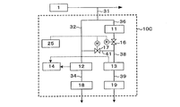
- FIG. 1 is a block diagram showing the configuration of a hydrogen peroxide concentration measurement system 10A according to an embodiment of the present invention.
- the hydrogen peroxide concentration measurement system 10 ⁇ / b> A is a part of water before or after being treated in a water treatment process 1 such as pure water or ultrapure water production equipment or wastewater treatment equipment.
- a sample water collection pipe sample water collection means
- the sample water is introduced into the first dissolved oxygen concentration meter (first dissolved oxygen concentration measuring means) 12 via the first pipe 32 and a path for measuring the dissolved oxygen concentration of the sample water, and the sample water is decomposed with hydrogen peroxide.
- the treated water introduced into the apparatus (hydrogen peroxide decomposition means) 11 and decomposed hydrogen peroxide is introduced into the second dissolved oxygen concentration meter (second dissolved oxygen concentration measuring means) 13 via the second pipe 38 and dissolved. Branching to a pipe 36 connected to a path for measuring the oxygen concentration.
- the first dissolved oxygen concentration meter 12 accepts the sample water as it is and measures the dissolved oxygen concentration in the sample water.
- the hydrogen peroxide decomposition apparatus 11 receives sample water, decomposes hydrogen peroxide in the sample water, and discharges it as treated water.
- the second dissolved oxygen concentration meter receives the discharged treated water and measures the dissolved oxygen concentration in the treated water.
- the specimen water collection pipe 31 is branched and divided into two measurement systems (paths).
- the sample water flowing into the first pipe 32 on one side of the branch is sent to the first dissolved oxygen concentration meter 12 via the first on-off valve 15.
- the sample water that has flowed into the other pipe 36 passes through the hydrogen peroxide decomposing apparatus 11 and undergoes a hydrogen peroxide decomposing process.
- the treated water passes through the second pipe 38 having the second on-off valve 16. It is sent to the second dissolved oxygen concentration meter 13 via.
- a communication pipe 41 that communicates the downstream side of the first on-off valve 15 of the pipe 32 and the downstream side of the second on-off valve 16 of the pipe 38 is provided.
- a communication valve 17 is provided in the communication pipe 41.
- the sample water collection pipe 31 may be provided with a gate valve used when sample water is not collected.
- a liquid feeding device such as a pump is unnecessary, but a liquid feeding device may be provided if necessary.
- the first on-off valve 15, the second on-off valve 16, and the communication valve 17 are all automatic open / close valves that are operated by electricity or compressed air, and are controlled to open and close by the valve control device (valve control means) 25 including the opening / closing timing.
- the dissolved oxygen concentration values measured by the first dissolved oxygen concentration meter 12 and the second dissolved oxygen concentration meter 13 are transmitted to the calculation unit (calculation means) 14 to calculate the hydrogen peroxide concentration in the sample water.
- a display device that displays the measured dissolved oxygen concentration value or the calculated hydrogen peroxide concentration value on a monitor screen or the like in real time, or an output device that appropriately prints on a printer or the like may be provided (not shown).
- Hydrogen peroxide contained in the sample water introduced into the hydrogen peroxide decomposition apparatus 11 is decomposed as follows.
- the generated oxygen dissolves in water and becomes dissolved oxygen. 2H 2 O 2 ⁇ 2H 2 O + O 2 (1)
- the hydrogen peroxide decomposition apparatus 11 may be constituted by a container or a column filled with a material having hydrogen peroxide decomposition ability.
- the material having the ability to decompose hydrogen peroxide is not particularly limited as long as it has the ability to decompose hydrogen peroxide in water into water and oxygen. Those having high ability and excellent durability are preferred. Further, in order to increase the contact efficiency with hydrogen peroxide, those having a large surface area such as granular, fibrous or porous are preferable. Examples of such materials include activated carbon, synthetic carbon-based adsorbent, ion exchange resin, metal catalyst (Pd, Pt, etc.), enzyme (catalase, etc.), enzyme carrier and the like.
- the hydrogen peroxide decomposition catalyst it is preferable to use a catalyst metal carrier (platinum group metal catalyst) on which a platinum group metal is supported.
- Hydrogen peroxide can be decomposed by catalytic decomposition by bringing hydrogen peroxide in the water to be treated into contact with a platinum group metal catalyst.
- the platinum group metal catalyst is supported on an anion exchanger.
- the anion exchanger may be a granular anion exchange resin.
- a catalytic metal carrier in which a platinum group metal is supported on a monolithic organic porous anion exchanger can decompose hydrogen peroxide even when water is passed at an SV (space velocity) exceeding 2000 h- 1 . For this reason, the hydrogen peroxide decomposition apparatus 11 can be easily downsized.
- the synergistic effect of the increase in SV and the downsizing of the hydrogen peroxide decomposition means enables high-speed water flow. For this reason, oxygen remaining in the catalyst itself and the packed column is easily removed, the system startup speed is improved, and rapid measurement is possible. Even when oxygen is mixed in through the joint, the increase in SV makes it easier to exclude oxygen, so that adverse effects on measurement accuracy can be suppressed.
- a Pd monolith in which Pd is supported on a monolithic organic porous anion exchanger as a platinum group metal water to be measured can be passed at high speed, the apparatus can be easily downsized.
- the influence can be suppressed, for example, also when air mixes from the upstream piping of the hydrogen peroxide decomposition apparatus. For example, when air is mixed intermittently, because of the high SV, the air is immediately pushed downstream and does not stay in the hydrogen peroxide decomposition apparatus for a long time. Even when air is continuously mixed, since the SV is large, the air is diluted and the influence on the measured value is mitigated. For this reason, analysis accuracy can be improved.
- air remains in the catalyst itself or packed column when the system is started up, it is necessary to wait until the air is removed and the measured value stabilizes. System startup time is reduced.
- the monolith anion exchanger are the A type and B type described below. Catalyst metal carriers in which a platinum group metal is supported on these monolith anion exchangers can be suitably applied to the hydrogen peroxide decomposition apparatus 11.
- the A type monolith anion exchanger is obtained by introducing an anion exchange group into the monolith.
- the macropores in the form of bubbles overlap each other, and the overlapping portion is in a wet state in water with an average diameter of 30 to 300 ⁇ m, preferably 30 A continuous macropore structure having an opening (mesopore) of ⁇ 200 ⁇ m, particularly preferably 40 to 100 ⁇ m.
- the average diameter of the A-type monolith anion exchanger opening is larger than the average diameter of the monolith opening because the entire monolith swells when an anion exchange group is introduced into the monolith.
- the average diameter of the openings in the water wet state is 30 ⁇ m or more, it is possible to easily prevent an increase in pressure loss during water flow.
- the average diameter of the openings in the water-wetting state is 300 ⁇ m or less, it is easy to ensure the contact between the water to be treated and the A-type monolith anion exchanger and the supported platinum group metal nanoparticles. Further, it is possible to easily prevent the degradation of hydrogen peroxide decomposition characteristics.
- the average diameter of the opening of the monolith intermediate in the dry state, the average diameter of the opening of the monolith in the dry state, and the average diameter of the opening of the monolith anion exchanger in the dry state mean values measured by the mercury intrusion method.
- the average diameter of the openings of the A-type monolith anion exchanger in the wet state is a value calculated by multiplying the average diameter of the openings of the A-type monolith anion exchanger in the dry state by the swelling rate. Further, the average diameter of the opening of the dried monolith before the introduction of the anion exchange group, and the swelling of the water-type A type monolith anion exchanger with respect to the dried monolith when the anion exchange group is introduced into the dried monolith When the ratio is known, the average diameter of the opening of the dry monolith can be multiplied by the swelling ratio to calculate the average diameter of the opening of the A-type monolith anion exchanger in the wet state.
- the skeleton part area appearing in the cross section is 25 to 50%, preferably 25 to 45% in the image region.
- the area of the skeleton part shown in the cross section is 25% or more in the image region, it can be easily prevented that the skeleton becomes a thin skeleton and the mechanical strength is lowered, and the monolith anion exchanger particularly when water is passed at a high flow rate. Can be easily prevented from being greatly deformed.
- the total pore volume of the A type monolith anion exchanger is 0.5 to 5 ml / g, preferably 0.8 to 4 ml / g.
- the total pore volume is 0.5 ml / g or more, it is possible to easily prevent an increase in pressure loss during water flow, and the amount of permeated fluid per unit cross-sectional area is reduced, resulting in a reduction in processing capacity. Can be easily prevented.
- the total pore volume is 5 ml / g or less, it is possible to easily prevent the mechanical strength from decreasing, and particularly when the water is passed at a high flow rate, the A type monolith anion exchanger is greatly deformed. Can be easily prevented.
- the total pore volume of the monolith means a value measured by mercury porosimetry.
- the total pore volume of the monolith is the same both in the dry state and in the water wet state.
- the pressure loss when water is permeated through the A-type monolith anion exchanger is the pressure loss when water is passed through a column packed with 1 m at a water flow velocity (LV) of 1 m / h (hereinafter, “In the range of 0.001 to 0.1 MPa / m ⁇ LV, particularly 0.005 to 0.05 MPa / m ⁇ LV is preferable.
- the A type monolith anion exchanger has an anion exchange capacity of 0.4 to 1.0 mg equivalent / ml per volume in a water-wet state.
- the anion exchange capacity per volume is 0.4 mg equivalent / ml or more, it is possible to easily prevent the supported amount of platinum group metal nanoparticles per volume.
- the anion exchange capacity per volume is 1.0 mg equivalent / ml or less, an increase in pressure loss during water passage can be easily prevented.
- the anion exchange capacity per weight of the A type monolith anion exchanger is not particularly limited. However, since the anion exchange group is uniformly introduced to the surface of the porous body and the inside of the skeleton, it is 3.5 to 4. 5 mg equivalent / g.
- the material constituting the skeleton of the continuous macropore structure is an organic polymer material having a crosslinked structure.
- the crosslink density of the polymer material is not particularly limited, but includes 0.3 to 10 mol%, preferably 0.3 to 5 mol% of cross-linked structural units with respect to all structural units constituting the polymer material. It is preferable.
- the cross-linking structural unit is 0.3 mol% or more, it is possible to easily prevent the mechanical strength from being insufficient.
- it is 10 mol% or less it is easy to introduce an anion exchange group. Can be prevented.
- aromatic vinyl polymers such as a polystyrene
- the polymer may be a polymer obtained by copolymerizing a single vinyl monomer and a crosslinking agent, a polymer obtained by polymerizing a plurality of vinyl monomers and a crosslinking agent, or a blend of two or more types of polymers. It may be what was done.
- the cross-linking weight of the aromatic vinyl polymer is easy due to the ease of forming a continuous macropore structure, the ease of introducing an anion exchange group and the high mechanical strength, and the high stability to acids or alkalis.
- a styrene-divinylbenzene copolymer and a vinylbenzyl chloride-divinylbenzene copolymer are particularly preferable materials.
- anion exchange groups of the A type monolith anion exchanger quaternary ammonium groups such as trimethylammonium group, triethylammonium group, tributylammonium group, dimethylhydroxyethylammonium group, dimethylhydroxypropylammonium group, methyldihydroxyethylammonium group, etc. Is mentioned.
- anion exchange groups are uniformly distributed” means that the distribution of anion exchange groups is uniformly distributed on the surface and inside the skeleton in the order of at least ⁇ m.
- the distribution state of the anion exchange group can be confirmed relatively easily by using EPMA after ion exchange of the counter anion with chloride ion, bromide ion or the like.
- the anion exchange groups are uniformly distributed not only on the surface of the monolith but also within the skeleton of the porous body, the physical and chemical properties of the surface and the interior can be made uniform, so that the swelling and shrinking The durability against is improved.
- the A type monolith anion exchanger swells greatly, for example, 1.4 to 1.9 times as thick as the bone monolith, since an anion exchange group is introduced into the bone monolith. For this reason, even if the opening diameter of the thick monolith is small, the opening diameter of the monolith ion exchanger generally increases at the above magnification. In addition, the total pore volume does not change even when the opening diameter increases due to swelling. Therefore, the A-type monolith ion exchanger has a high mechanical strength because it has a thick bone skeleton even though the opening diameter is remarkably large.
- the B type monolith anion exchanger has an average thickness composed of an aromatic vinyl polymer containing 0.3 to 5.0 mol% of a cross-linking structural unit in all constituent units into which an anion exchange group has been introduced.
- a co-continuous structure comprising a three-dimensionally continuous skeleton of 1 to 60 ⁇ m and three-dimensionally continuous pores having an average diameter of 10 to 100 ⁇ m in a wet state between the skeletons.
- the volume is 0.5 to 5 ml / g
- the ion exchange capacity per volume under water wet condition is 0.3 to 1.0 mg equivalent / ml
- the anion exchange group is uniform in the porous ion exchanger. Is distributed.
- the B type monolith anion exchanger has a three-dimensional continuous skeleton having an average thickness of 1 to 60 ⁇ m, preferably 3 to 58 ⁇ m in an wet state in which an anion exchange group is introduced, and an average diameter between the skeletons.
- a co-continuous structure comprising three-dimensionally continuous pores of 10 to 100 ⁇ m, preferably 15 to 90 ⁇ m, particularly preferably 20 to 80 ⁇ m in a wet state. That is, the co-continuous structure is a structure in which a continuous skeleton phase and a continuous vacancy phase are intertwined and both are three-dimensionally continuous.
- the skeleton thickness and pore diameter of the B type monolith anion exchanger are larger than the monolith skeleton thickness and pore diameter because the entire monolith swells when an anion exchange group is introduced into the monolith. It becomes.
- These continuous pores have higher continuity of the pores than the conventional open-cell type monolithic organic porous anion exchanger and particle aggregation type monolithic organic porous anion exchanger, and the size thereof is not biased. Therefore, an extremely uniform anion adsorption behavior can be achieved.
- the average diameter of the three-dimensionally continuous pores is 10 ⁇ m or more in a water-wet state, it is possible to easily prevent an increase in pressure loss during water flow.
- the average diameter is 100 ⁇ m or less
- the water to be treated and the organic porosity It is easy to ensure contact with the porous anion exchanger, and as a result, it is easy to remove dissolved oxygen from the water to be treated.
- the average thickness of the skeleton is 1 ⁇ m or more in a wet state of water, it is possible to easily prevent a decrease in anion exchange capacity per volume, a decrease in mechanical strength, especially when water is passed at a high flow rate.
- the B-type monolith anion exchanger can be easily prevented from being greatly deformed. Furthermore, it can prevent easily that the contact efficiency of to-be-processed water and a B type monolith anion exchanger falls, and a catalyst effect falls.
- the thickness of the skeleton is 60 ⁇ m or less, it is possible to easily prevent the skeleton from becoming thick and increasing pressure loss during water passage.
- the average diameter of the pores of the continuous structure in the water-wet state is a value calculated by multiplying the average diameter of the pores of the dry monolith anion exchanger measured by the mercury intrusion method and the swelling ratio.
- the average diameter of the pores of the dried monolith before the introduction of the anion exchange group, and the water-wet state B type monolith anion exchanger of the dried monolith when the anion exchange group is introduced into the dried monolith can be calculated by multiplying the average diameter of the pores of the dry monolith by the swelling ratio.
- the average thickness of the skeleton of the continuous structure in the water-wet state is determined by performing SEM observation of the dry B-type monolith anion exchanger at least three times and measuring the thickness of the skeleton in the obtained image. The average value is calculated by multiplying the swelling ratio. Further, the average thickness of the skeleton of the dried monolith before the introduction of the anion exchange group, and the water-wet state B type monolith anion exchanger of the dried monolith when the anion exchange group is introduced into the dried monolith. When the swelling ratio is known, the average thickness of the skeleton of the monolith anion exchanger in the water-wet state can be calculated by multiplying the average thickness of the skeleton of the monolith in the dry state by the swelling ratio.
- the skeleton has a rod-like shape and a circular cross-sectional shape, but may have a cross-section with a different diameter such as an elliptical cross-sectional shape.
- the thickness in this case is the average of the minor axis and the major axis.
- the total pore volume of the B type monolith anion exchanger is 0.5 to 5 ml / g.
- the total pore volume is 0.5 ml / g or more, it is possible to easily prevent an increase in pressure loss during water flow, and further, the amount of permeated water per unit cross-sectional area is reduced and the amount of treated water is reduced. Can be easily prevented.
- the total pore volume is 5 ml / g or less, it is possible to easily prevent a decrease in anion exchange capacity per volume and a decrease in the catalytic effect due to a decrease in the amount of platinum group metal nanoparticles supported. .
- the pressure loss when water is allowed to permeate through the B type monolith anion exchanger is the pressure loss when water is passed through a column filled with 1 m of a porous material at a water flow rate (LV) of 1 m / h (hereinafter referred to as “pressure loss”).
- pressure loss a water flow rate of 1 m / h
- pressure loss a water flow rate of 1 m / h
- the material constituting the skeleton of the co-continuous structure contains 0.3 to 5 mol%, preferably 0.5 to 3.0 mol% of cross-linked structural units in all the structural units. It is an aromatic vinyl polymer containing and is hydrophobic.
- the cross-linking structural unit is 0.3 mol% or more, it is possible to easily prevent the mechanical strength from being insufficient.
- the structure of the porous body deviates from the bicontinuous structure. Can be easily prevented.
- the polymer may be a polymer obtained by copolymerizing a single vinyl monomer and a crosslinking agent, a polymer obtained by polymerizing a plurality of vinyl monomers and a crosslinking agent, or a blend of two or more types of polymers. It may be what was done.
- organic polymer materials a styrene-divinylbenzene copolymer is obtained due to the ease of forming a co-continuous structure, the ease of introducing an anion exchange group and the high mechanical strength, and the high stability to acids or alkalis. And vinylbenzyl chloride-divinylbenzene copolymer is preferred.
- the B-type monolith anion exchanger has an ion exchange capacity of 0.3 to 1.0 mg equivalent / ml per anion volume in a wet state of water. Since the B type monolith anion exchanger has high continuity and uniformity of three-dimensionally continuous pores, the pressure loss does not increase so much even if the total pore volume is reduced. Therefore, the anion exchange capacity per volume can be dramatically increased while keeping the pressure loss low. When the anion exchange capacity per volume is 0.3 mg equivalent / ml or more, it is possible to easily prevent the supported amount of platinum group metal nanoparticles per volume. On the other hand, when the anion exchange capacity per volume is 1.0 mg equivalent / ml or less, an increase in pressure loss during water passage can be easily prevented.
- the anion exchange capacity per weight in the dry state of the B type monolith anion exchanger is not particularly limited, but the ion exchange groups are uniformly introduced to the skeleton surface and the skeleton inside the porous body. 5 to 4.5 mg equivalent / g.
- anion exchange group of the B type monolith anion exchanger examples include the same as those mentioned in the description of the A type monolith anion exchanger.
- distribution of anion exchange groups, the meaning of “anion exchange groups are uniformly distributed”, the method for confirming the distribution of anion exchange groups, and the anion exchange groups are porous as well as the surface of the monolith. The effect of even distribution within the body skeleton is the same as that of the A-type monolith anion exchanger.
- the kind of the polymer material of the monolith intermediate is the same as the kind of the polymer material of the monolith intermediate of the A type monolith anion exchanger, and the description thereof is omitted.
- the total pore volume of the monolith intermediate is more than 16 ml / g and not more than 30 ml / g, preferably more than 16 ml / g and not more than 25 ml / g.
- this monolith intermediate basically has a continuous macropore structure, but the opening (mesopore) that is the overlapping part of the macropore and the macropore is remarkably large, so that the skeleton constituting the monolith structure is primary from the two-dimensional wall surface. It has a structure as close as possible to the original rod-like skeleton.
- a porous body having a co-continuous structure is formed using the structure of the monolith intermediate as a mold.
- the ratio of monomer to water may be about 1:20 to 1:40.
- the average diameter of openings is 5 to 100 ⁇ m in a dry state.
- the average diameter of the openings is 5 ⁇ m or more in the dry state, it is possible to easily prevent the opening diameter of the monolith obtained after polymerizing the vinyl monomer from decreasing and the pressure loss during fluid permeation from increasing.
- it is 100 ⁇ m or less it is possible to easily prevent an increase in the opening diameter of the monolith obtained after polymerizing the vinyl monomer, and it is easy to ensure contact between the water to be treated and the monolith anion exchanger.
- Monolith intermediates preferably have a uniform structure with uniform macropore size and aperture diameter, but are not limited to this, and the uniform structure is dotted with nonuniform macropores larger than the size of the uniform macropore. You may do.
- B-type monolith anion exchangers swell 1.4 to 1.9 times larger than monoliths, for example, because anion exchange groups are introduced into monoliths having a co-continuous structure. Further, the total pore volume does not change even if the pore diameter becomes larger due to swelling. Therefore, the B type monolith anion exchanger has a high mechanical strength because it has a thick bone skeleton even though the size of three-dimensionally continuous pores is remarkably large. Further, since the skeleton is thick, the anion exchange capacity per volume in a water-wet state can be increased, and furthermore, the water to be treated can be passed for a long time at a low pressure and a large flow rate.
- sample water line the analysis line for measuring the dissolved oxygen concentration of the sample water
- treated water line the analysis line for measuring the dissolved oxygen concentration of the treated water
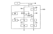
- the hydrogen peroxide decomposing apparatus 11 Since the hydrogen peroxide decomposing apparatus 11 is mounted, the pressure loss is larger and the number of joints is different. As a result, the measured values of the first dissolved oxygen concentration meter 12 and the second dissolved oxygen concentration meter 13 installed in the subsequent stage may be changed. Therefore, as in the hydrogen peroxide concentration measurement system 10B shown in FIG. 2, the condition adjustment unit 20 may be provided upstream of the first on-off valve 15 of the pipe 32 of the sample water line.
- the condition adjustment unit 20 is filled with a material (hereinafter referred to as a condition adjustment material) that matches the water flow conditions of the sample water line and the treated water line, such as causing a pressure loss similar to that of the hydrogen peroxide decomposition apparatus 11. It can be configured as a column (container).
- the condition adjustment unit 20 is not particularly limited as long as it does not have a function of generating oxygen, such as a hydrogen peroxide decomposition reaction, but is not dissolved in water and has excellent durability. Those are preferred.
- condition adjusting unit 20 may be a column packed only with the carrier as a condition adjusting material. it can.
- Such a condition adjustment unit 20 can also be applied to the configurations shown in FIGS.
- the column water flow rate is appropriately determined according to various conditions such as the type of packing material and the concentration of hydrogen peroxide in the sample water to be analyzed. It is determined.
- the flow rate is lowered, the contact time between the hydrogen peroxide and the packing material increases, the hydrogen peroxide decomposition rate increases, and the oxygen production rate tends to increase.
- the oxygen production rate through the column and piping system tends to increase. Permeation tends to cause an increase in dissolved oxygen concentration.
- the material of the column filled with the material having the ability to decompose hydrogen peroxide is not particularly limited, but a material having a low oxygen permeability is preferable. Moreover, it is transparent so that the presence or absence of air bubbles in the column can be confirmed at the time of starting the system, and preferably excellent in durability. Examples of such materials include acrylic, vinyl chloride, polycarbonate, and the like.
- the dissolved oxygen contained in the sample water and the treated water is measured by the first dissolved oxygen concentration meter 12 and the second dissolved oxygen concentration meter 13 (measurement value acquisition step).
- the two dissolved oxygen concentration meters 12 and 13 can be constituted by known dissolved oxygen meters.
- the two dissolved oxygen concentration meters 12 and 13 are not particularly limited, but are preferably of the same type and lot in order to minimize individual differences as much as possible.
- the measured values of the two dissolved oxygen concentration meters 12 and 13 are transmitted to the calculation unit 14, and the calculation unit 14 calculates the hydrogen peroxide concentration in the sample water based on a predetermined calculation formula.
- the hydrogen peroxide concentration from the dissolved oxygen concentration it can be obtained by the following calculation. That is, the difference between the dissolved oxygen concentrations in the treated water and the sample water (the numerical value obtained by subtracting the measured value of the first dissolved oxygen concentration meter 12 from the measured value of the second dissolved oxygen concentration meter 13) is as shown in the equation (1). It is derived from hydrogen peroxide. Accordingly, the concentration of hydrogen peroxide contained in the sample water can be calculated from the following equation based on the difference in the measured dissolved oxygen concentration.
- the difference ⁇ 1 between the dissolved oxygen concentration values in the treated water and the sample water (this difference ⁇ 1 obtained in the measurement value acquisition step is also referred to as “measured value”) is (treated water DO ⁇ sample water).
- 68 is the molecular weight of hydrogen peroxide on the left side of Formula (1) (doubled because it is 2 molecules)
- 32 is the molecular weight of oxygen on the right side of Formula (1).
- the unit on the left side is the same as the unit of DO on the right side.
- the dissolved oxygen concentration meter is adjusted so that there is the least error in the predetermined flow rate range, it is preferable to adjust the flow rate within that range. Therefore, it is preferable to provide a flow meter after the dissolved oxygen concentration meter. Thereby, the sample water and the treated water can be supplied to the hydrogen peroxide decomposition catalyst and the dissolved oxygen concentration meter at an appropriate flow rate.
- a mechanism for indicating the flow rate and stabilizing the flow rate at an appropriate value (hereinafter referred to as flow rate stabilizing means).
- a flow rate stabilization device (flow rate stabilization unit) 18 is provided in the downstream pipe 34 of the first dissolved oxygen concentration meter 12, and a flow rate stabilization device (flow rate stabilization unit) is provided in the downstream pipe 39 of the second dissolved oxygen concentration meter 13. ) 19 is provided.
- the flow rate stabilizing means 18 and 19 are not particularly limited, and examples thereof include a combination of a flow meter and a valve capable of adjusting the flow rate (flow rate indicating controller).
- the flow stabilizing devices 18 and 19 are preferably provided downstream of the dissolved oxygen concentration meter because oxygen may enter from the joint.
- a well-known configuration can be arbitrarily added to the process control system such as an alarm device.
- the sample water and the treated water whose dissolved oxygen concentration has been measured are drained after the flow rate measurement. Since no measurement reagent or the like is added, waste water treatment is easy.
- a dissolved oxygen concentration meter It is desirable to calibrate and use the dissolved oxygen concentration meter.
- calibration of a dissolved oxygen concentration meter is generally performed by atmospheric calibration when the sensor is exposed to the atmosphere and / or zero point calibration with an aqueous solution in which a reducing agent such as sodium sulfite is excessively dissolved to remove the dissolved oxygen concentration. .
- a reducing agent such as sodium sulfite
- the minute individual difference becomes more problematic.
- either one of the sample water or the treated water is simultaneously passed through both of the two dissolved oxygen concentration meters 12 and 13 to obtain a difference between the measured values (correction value acquisition step). ), A correction value for correcting individual differences between the dissolved oxygen concentration meters 12 and 13.
- the measured values of the two dissolved oxygen concentration meters 12 and 13 are transmitted to the calculation unit 14, and the calculation unit 14 calculates the individual difference between the two dissolved oxygen concentration meters 12 and 13 based on a predetermined calculation formula. Is calculated (calculation step).
- the measured value of the first dissolved oxygen concentration meter 12 is A
- the two dissolved oxygen concentration meters should be flowed at the same flow rate. Is preferred.
- a flow rate stabilizing means for stabilizing the flow rate at an appropriate value downstream of the dissolved oxygen concentration meter.
- valve opening / closing control will be described.
- the first on-off valve 15 is opened, the second on-off valve 16 is opened, and the communication valve 17 is closed.
- the first on-off valve 15 may be opened, the second on-off valve 16 may be closed, and the communication valve 17 may be opened (“ First correction value acquisition mode ”).
- the first on-off valve 15 may be closed, the second on-off valve 16 may be opened, and the communication valve 17 may be opened (“second correction value acquisition mode”).
- the first correction value acquisition mode and the second correction value acquisition mode are both “correction value acquisition modes”.
- the opening / closing control of each valve is configured to be performed using the valve control device 25, but each valve may be manually opened / closed without using the valve control device 25. The same applies to other embodiments.
- the communication valve 17 is not particularly limited, but a communication valve 17 having no restriction in the flow direction is preferable.
- FIG. 3 shows a hydrogen peroxide concentration measurement system 10C in the case where the sample water is measured using two dissolved oxygen concentration meters when calculating the correction value.
- This system 10C does not have the first on-off valve 15 as compared with FIG. 1, and the valve 16 serves as the first on-off valve.
- FIG. 4 shows a hydrogen peroxide concentration measurement system 10D in the case of measuring treated water using two dissolved oxygen concentration meters when calculating a correction value.
- This system 10D has only the first on-off valve 15 without the second on-off valve 16 as compared with FIG. Since other than that is the same as that of FIG. 1, detailed description is abbreviate
- the communication valve 17 in the measurement value acquisition mode, the communication valve 17 is closed and the first on-off valve 16 is opened. In the correction value acquisition mode, the communication valve 17 is open and the first on-off valve 16 is closed. In the configuration of FIG. 4, in the measurement value acquisition mode, the communication valve 17 is closed and the first on-off valve 15 is opened. In the correction value acquisition mode, the communication valve 17 is open and the first on-off valve 15 is closed.
- the number of valves can be reduced compared to the configuration of FIG. Thereby, the amount of oxygen entering the water from the valve can be reduced, and the maintenance of the valve can also be reduced.
- both the state in which the first on-off valve 15 is opened, the second on-off valve 16 is opened, and the communication valve 17 is closed at the time of normal hydrogen peroxide concentration measurement (measurement value acquisition mode) and the sample water are both used.
- the first open / close valve 15 is opened
- the second open / close valve 16 is closed
- the communication valve 17 is opened (correction value acquisition mode) when calculating the correction value by introducing it into the dissolved oxygen concentration meter
- the timing of valve switching will be described.
- Second correction value acquisition mode when switching from a normal hydrogen peroxide concentration measurement state (measurement value acquisition mode) to a state in which sample water is introduced into both dissolved oxygen concentration meters and a correction value is calculated (first correction value acquisition mode), 2
- the timing of switching the on-off valve 16 from opening to closing and the switching of the communication valve 17 from closing to opening can be arbitrarily set, and can be set at the same time. It is preferable to switch the second on-off valve 16 from open to closed after the switch to open is completed. This is because if the communication valve 17 is opened from the closed state after the second on-off valve 16 is switched from the open state to the closed state, the flow rate to the second dissolved oxygen concentration meter 13 is temporarily interrupted, and it takes time until the measured value becomes stable. This is because problems such as having
- the communication valve 17 is switched from open to closed after the switching of the second open / close valve 16 from closed to open is completed.
- the first on-off valve 15 and the communication valve 17 are switched at the same timing as described above.
- the timing for obtaining the correction value ⁇ 2 (the timing for performing the correction value acquisition step) can be set arbitrarily (regular or irregular), but is preferably between every day and every six months. With a frequency of every day or more, it can be easily prevented that the mode for frequently obtaining the correction value is switched and the time during which the hydrogen peroxide concentration cannot be output becomes long. In addition, when the frequency is less than half a year, the calibration frequency of the sensor is moderated, and it is possible to easily prevent the measurement value from becoming unreliable. It is preferable that the measurement value acquisition process is continuously performed during a period other than the period during which the correction value acquisition process is performed.
- sample water As the water to be measured when obtaining the correction value ⁇ 2.
- the dissolved oxygen concentration in the sample water is always output. That is, the dissolved oxygen concentration can be monitored even during the acquisition of the correction value ⁇ 2.
- a more reliable measurement value can be obtained by performing normal calibration (such as atmospheric calibration and / or zero point calibration) of the dissolved oxygen concentration meter as appropriate.
- the hydrogen peroxide concentration is calculated from equation (3), but it is possible to suppress variations by taking a moving average over a certain period of time.
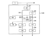
- a degassing device (degassing means) 21 is provided in the pipe 31 for collecting the sample water to degas the oxygen dissolved in the sample water. Also good.
- a membrane type deaerator is used as the deaerator 21. The membrane type deaerator flows the water to be treated into one chamber partitioned by a gas separation membrane and depressurizes the other chamber so that the gas contained in the water to be treated passes through the gas separation membrane to the other chamber. A device that migrates and removes.
- a membrane in which a hydrophobic polymer membrane such as tetrafluoroethylene or silicone rubber is formed into an appropriate shape such as a hollow fiber membrane is usually used.
- a deaeration device is effective for measuring the hydrogen peroxide concentration with high accuracy when the dissolved oxygen concentration in the specimen water is high or fluctuates greatly.
- the deaeration device 21 can also be applied to the configurations of FIGS.
- the hydrogen peroxide concentration of pure water or ultrapure water is several tens of ⁇ g / L or less, so the dissolved oxygen concentration is 100 ⁇ g / L or less to reduce the blank value. It is particularly preferable to deaerate (deoxygenate) to 10 ⁇ g / L or less.
- the method of deaeration (deoxygenation) is not particularly limited, but the above-mentioned membrane type deaerator is preferable in that a high-grade deaeration process can be performed in a compact manner. If the hydrogen peroxide concentration in the sample water is high or analysis with high accuracy is not required, or if the dissolved oxygen concentration in the sample water is originally low, it is not always necessary to install a deaeration device.
- the pipes used in the hydrogen peroxide concentration measurement system described above especially the pipe from the sample collection point where the sample water is introduced to the dissolved oxygen concentration meter, use a material such as stainless steel or nylon with low gas permeability. It is preferable. These are preferable because of low oxygen permeability and less elution of impurities.
- the sample water collected by the pipe 31 is measured separately for the sample water line and the treated water line.
- the sample water for the sample water line and the sample water line may be collected independently (not shown).
- the conditions such as the dissolved oxygen concentration may be different if the collection position is far away, it is preferable to measure by branching the sample water collected at one place.
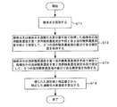
- sample water is collected (step S11 in FIG. 7).
- the dissolved oxygen concentration of the sample water or the treated water obtained by treating the sample water with the hydrogen peroxide decomposing means is measured by the first dissolved oxygen concentration measuring means and the second dissolved oxygen concentration measuring means, and the two dissolved oxygen concentrations are measured.
- a correction value that is a difference between the values is acquired (step S12).
- the dissolved oxygen concentration in the sample water is measured by the first dissolved oxygen concentration measuring means, the dissolved oxygen concentration in the treated water is measured by the second dissolved oxygen concentration measuring means, and the measurement is the difference between the two dissolved oxygen concentration values.
- a value is acquired (step S13).
- step S14 The hydrogen peroxide concentration corrected from the measured value and the correction value obtained at the end is calculated (step S14).
- Step 12 is appropriately performed, and step S13 and step S14 are performed simultaneously at other normal times. That is, the hydrogen peroxide concentration is calculated by correcting the measurement value obtained continuously continuously with the correction value immediately.
- hydrogen peroxide in the sample water can be quantified continuously and with high accuracy.
- the measurement of the hydrogen peroxide concentration in the sample water can be automated, it is possible to realize a hydrogen peroxide analysis system and method that are particularly suitable for pure water or ultrapure water production facilities that should avoid human intervention as much as possible.
- Example 1 Four conditions of sample water with different hydrogen peroxide concentrations were introduced into the hydrogen peroxide concentration measurement system 10E shown in FIG. 5, and the hydrogen peroxide concentration was measured.
- the sample water was simultaneously passed through both the first dissolved oxygen concentration meter 12 and the second dissolved oxygen concentration meter 13 for 1 hour, both of which were in the latter half 30 minutes.
- the correction value ⁇ 2 for calculating the hydrogen peroxide concentration was calculated using the average value of the difference between the measured values. Thereafter, the hydrogen peroxide concentration was calculated by the formula (3).
- the dissolved oxygen concentration contained in the sample water and the treated water is measured simultaneously with two dissolved oxygen concentration meters, and the average value for 3 minutes after the measurement value is stabilized is calculated.
- the measured value of the hydrogen peroxide concentration was used.
- the hydrogen peroxide concentration in the sample water was analyzed by the phenolphthalein colorimetric method described in Patent Document 3.
- Example 1 the hydrogen peroxide concentration measurement result (Example 1) of the sample water according to the present invention and the hydrogen peroxide concentration measurement result (reference value) of the sample water by the phenolphthalein colorimetric method were obtained.
- the results are shown in Table 1. Comparing the measurement results of Example 1 and the reference value, the difference was 0.5 ⁇ g / L or less in all four conditions with different hydrogen peroxide concentrations in the sample water.
- the dissolved oxygen concentration contained in the sample water and the treated water is simultaneously measured by the calibrated first dissolved oxygen concentration meter 12 and the second dissolved oxygen concentration meter 13, respectively, and the equation (2) is used from the measured dissolved oxygen concentration.
- the hydrogen peroxide concentration was calculated.
- the dissolved oxygen concentration contained in the sample water and the treated water is measured simultaneously with the first dissolved oxygen concentration meter 12 and the second dissolved oxygen concentration meter 13 respectively, and the average value for 3 minutes after the measured value becomes stable is measured.
- the measured value of the hydrogen peroxide concentration in water was used. Further, the hydrogen peroxide concentration in the sample water was analyzed by the phenolphthalein colorimetric method described in Patent Document 3.
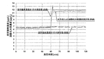
- Example 2 Ultrapure water containing hydrogen peroxide was introduced as sample water into the hydrogen peroxide concentration measurement system 10E shown in FIG. 5, and the hydrogen peroxide concentration was measured. Immediately before the measurement of the hydrogen peroxide concentration, the sample water was passed through both the first dissolved oxygen concentration meter 12 and the second dissolved oxygen concentration meter 13 simultaneously for 1 hour, and the difference between the measured values of the latter half 30 minutes was measured. A correction value ⁇ 2 for calculating the hydrogen peroxide concentration was calculated. Thereafter, the hydrogen peroxide concentration was calculated by the formula (3). The above results are shown in FIG.
Landscapes
- Life Sciences & Earth Sciences (AREA)
- Health & Medical Sciences (AREA)
- Chemical & Material Sciences (AREA)
- Pathology (AREA)
- General Physics & Mathematics (AREA)
- Immunology (AREA)
- Physics & Mathematics (AREA)
- Analytical Chemistry (AREA)
- Biochemistry (AREA)
- General Health & Medical Sciences (AREA)
- Food Science & Technology (AREA)
- Medicinal Chemistry (AREA)
- Engineering & Computer Science (AREA)
- Molecular Biology (AREA)
- Biophysics (AREA)
- Investigating Or Analyzing Non-Biological Materials By The Use Of Chemical Means (AREA)
- Investigating Or Analysing Materials By The Use Of Chemical Reactions (AREA)
Abstract
検体水中の過酸化水素を連続的かつ高精度で定量することができる過酸化水素濃度の測定方法および測定システムを提供する。水処理プロセスの所定位置から採取した検体水中の過酸化水素濃度を測定する方法であって、検体水を採取する採取工程と、検体水又は検体水を過酸化水素分解手段で処理した処理水の溶存酸素濃度を第1溶存酸素濃度測定手段と第2溶存酸素濃度測定手段とで測定して、2つの溶存酸素濃度値の差分である補正値を取得する補正値取得工程と、検体水中の溶存酸素濃度を第1溶存酸素濃度測定手段で測定し、処理水中の溶存酸素濃度を第2溶存酸素濃度測定手段で測定して、2つの溶存酸素濃度値の差分である測定値を取得する測定値取得工程と、測定値取得工程で得られた測定値と補正値取得工程で得られた補正値とから、補正した過酸化水素濃度を算出する演算工程と、を含む。
Description
本発明は、検体水中の微量な過酸化水素濃度を測定するための測定システムおよび測定方法に関する。
従来より、過酸化水素の濃度分析方法としては、試験紙または試験試薬による方法、比色法、酸化還元滴定法などが一般に知られている。このような過酸化水素の濃度分析は、種々の目的に使用されるが、例えば過酸化水素を含む排水の排水処理設備等で使用することができる。また、純水や超純水の製造設備においても、紫外線照射設備等で過酸化水素が発生することが知られており、過酸化水素の濃度分析の必要性が認識されつつある。純水や超純水の製造設備で過酸化水素の濃度分析を行うには、分析値がμg/Lレベル程度の微量分析が要求される。上述した各種分析方法のうち、試験紙または試験試薬による方法では、分析値がμg/Lレベルの測定は困難である。
また、比色法や酸化還元滴定法は、比色分析や滴定の操作が複雑であり、また、インラインの自動分析が困難であって、特に人間の介在を極力排除したい純水または超純水製造設備に不向きである。さらに、試薬を必要とするため、薬品コスト、メンテナンスおよび分析後の廃液処理などのために、コストが高くなる。
上記の課題に鑑み、水中の微量の過酸化水素を簡便に且つ高感度に分析できる過酸化水素分析装置および過酸化水素分析方法が特許文献1に開示されている。特許文献1に開示された発明は、過酸化水素分解手段と1台又は2台の溶存酸素濃度計によって検体水中の過酸化水素濃度を算出する方法である。具体的には、検体水中の溶存酸素濃度と過酸化水素分解手段で処理した処理水中の溶存酸素濃度との差分から、検体水中の過酸化水素濃度を算出する。その装置の実施形態の構成例を図8(特許文献1の図6に相当)および図9(特許文献1の図3に相当)に示す。図8では、検体水および処理水に含まれる溶存酸素濃度を、交互に1台の溶存酸素濃度計で測定する。図9では、検体水および処理水に含まれる溶存酸素濃度を、2台の溶存酸素濃度計で同時に測定する。
また、特許文献2には、過酸化水素分解手段にモノリス状有機多孔質アニオン交換体に白金族金属を担持させた触媒金属担持体を用いることを特徴とする過酸化水素濃度の測定装置及および測定方法も開示されている。特許文献3には固体状の発色試薬を用いたフェノールフタレイン比色法による過酸化水素濃度測定方法が開示されている。
溶存酸素濃度計が1台である図8の構成では、検体水および過酸化水素の分解処理がされた処理水に含まれる溶存酸素濃度をそれぞれ交互に測定した後に、検体水と処理水の溶存酸素濃度の差分から過酸化水素濃度を算出するため、検体水中の過酸化水素濃度を測定できない時間が頻繁に生じる。また、処理水に含まれる溶存酸素濃度を測定する間は検体水中の溶存酸素濃度を測定できない。また、検体水および処理水の切り替えを行うことで、切り替え後の溶存酸素濃度測定値が安定するまでに多少の時間を要する。
そこで溶存酸素濃度計を2台に増やした図9の構成では、同時に検体水および過酸化水素の分解処理がされた処理水の溶存酸素濃度を測定しながら、検体水と処理水の溶存酸素濃度の差分から過酸化水素濃度を算出するため、過酸化水素濃度を連続的に算出することができる。また、検体水中の溶存酸素濃度も連続的に測定できるという利点もある。しかしながら、2台の溶存酸素濃度計の僅かな個体差が過酸化水素濃度測定値の誤差につながるおそれがある。
上記に鑑みて、本発明は、検体水中の過酸化水素を連続的かつ高精度で定量することができる過酸化水素濃度の測定方法および測定システムを提供することを目的とする。
上記課題を解決するため、本発明に係る過酸化水素濃度測定方法は、
水処理プロセスの所定位置から採取した検体水中の過酸化水素濃度を測定する方法であって、
検体水を採取する採取工程と、
前記検体水又は前記検体水を過酸化水素分解手段で処理した処理水の溶存酸素濃度を第1溶存酸素濃度測定手段と第2溶存酸素濃度測定手段とで測定して、2つの溶存酸素濃度値の差分である補正値を取得する補正値取得工程と、
前記検体水中の溶存酸素濃度を前記第1溶存酸素濃度測定手段で測定し、前記処理水中の溶存酸素濃度を前記第2溶存酸素濃度測定手段で測定して、2つの溶存酸素濃度値の差分である測定値を取得する測定値取得工程と、
前記測定値取得工程で得られた前記測定値と前記補正値取得工程で得られた前記補正値とから、補正した過酸化水素濃度を算出する演算工程と、
を含む。
また、本発明に係る過酸化水素濃度測定システムは、
水処理プロセスの所定位置から採取した検体水中の過酸化水素濃度を測定する過酸化水素濃度測定システムであって、
前記検体水を採取する検体水採取手段と、
採取した前記検体水を第1配管を経由し第1溶存酸素濃度測定手段に導入して溶存酸素濃度を測定する経路と、
採取した前記検体水を過酸化水素分解手段に導入し、過酸化水素を分解処理した処理水を第2配管を経由し第2溶存酸素濃度測定手段に導入して溶存酸素濃度を測定する経路と、
前記第1配管と前記第2配管とを連通する連通配管と、
前記第1配管と前記第2配管の少なくともいずれかの配管の前記連通配管との分岐位置よりも上流側に配置された第1開閉弁と、
前記連通配管に配置された連通弁と、
前記第1開閉弁と前記連通弁を開閉制御する弁制御手段と、
前記第1溶存酸素濃度測定手段が測定した前記検体水の溶存酸素濃度値と前記第2溶存酸素濃度測定手段が測定した前記処理水の溶存酸素濃度値の差分である測定値と、前記第1及び第2溶存酸素濃度測定手段が測定した前記検体水又は前記処理水の溶存酸素濃度値の差分である補正値とから、補正した過酸化水素濃度を算出する演算手段と、
を備える。
本発明によれば、検体水中の過酸化水素を連続的かつ高精度に定量することができる過酸化水素濃度の測定方法および測定システムを提供することができる。
以下、本発明を実施するための形態(以下、実施形態という)を、図面に従って説明する。ただし、本発明は本実施形態に限定されるものではない。
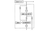
図1は、本発明の一実施形態にかかる過酸化水素濃度測定システム10Aの構成を表すブロック図である。図1に示すように、過酸化水素濃度測定システム10Aは、純水や超純水の製造設備、排水処理設備等の水処理プロセス1で処理する前、又は処理された後の水の一部を所定位置から、検体水採取用配管(検体水採取手段)31により分析対象となる検体水を採取し測定システム内に導入する。
検体水は、第1配管32を経由して第1溶存酸素濃度計(第1溶存酸素濃度測定手段)12に導入され検体水の溶存酸素濃度を測定する経路と、検体水を過酸化水素分解装置(過酸化水素分解手段)11に導入し過酸化水素を分解処理した処理水を第2配管38を経由し第2溶存酸素濃度計(第2溶存酸素濃度測定手段)13に導入して溶存酸素濃度を測定する経路につながる配管36とに分岐される。
即ち、第1溶存酸素濃度計12は、検体水をそのまま受け入れて検体水中の溶存酸素濃度を測定する。過酸化水素分解装置11は、検体水を受け入れて検体水中の過酸化水素を分解し、処理水として排出する。第2溶存酸素濃度計は、排出された処理水を受け入れて処理水中の溶存酸素濃度を測定する。
図1に示すように、検体水採取用配管31は分岐して2つの測定系統(経路)に分かれる。分岐の一方の第1配管32に流入した検体水は、第1開閉弁15を経由して第1溶存酸素濃度計12へ送られる。また、他方の配管36に流入した検体水は、過酸化水素分解装置11を通過して過酸化水素の分解処理を受け、処理された処理水は第2開閉弁16を有する第2配管38を経由して第2溶存酸素濃度計13に送られる。また配管32の第1開閉弁15の下流側と配管38の第2開閉弁16の下流側とを連通する連通配管41が設けられている。連通配管41には、連通弁17が設けられている。検体水採取用配管31には、検体水を採取しない場合に用いる仕切り弁を設けていてもよい。なお、採取した検体水は水処理プロセス1からの背圧を受けて流れるため、ポンプ等の送液装置は不要であるが、必要に応じて送液装置を備えてもよい。
第1開閉弁15、第2開閉弁16、連通弁17はいずれも電気又は圧空等で作動する自動開閉弁であり、弁制御装置(弁制御手段)25によって開閉のタイミングも含めて開閉制御される。第1溶存酸素濃度計12および第2溶存酸素濃度計13で測定された溶存酸素濃度値は演算部(演算手段)14に送信されて、検体水中の過酸化水素濃度が算出される。なお、測定された溶存酸素濃度値や計算された過酸化水素濃度値をリアルタイムでモニター画面等に表示する表示装置や、適宜プリンタ等に印刷する出力装置を設けてもよい(図示せず)。
過酸化水素分解装置11に導入された検体水中に含まれる過酸化水素は、以下のように分解される。なお、生成した酸素は水中に溶け込み、溶存酸素となる。
2H2O2 → 2H2O + O2 ・・・(1)
2H2O2 → 2H2O + O2 ・・・(1)
過酸化水素分解装置11は、過酸化水素分解能力を有する材料を充填した容器またはカラムにより構成してもよい。過酸化水素分解能力を有する材料は、水中の過酸化水素を水と酸素に分解する能力を有するものであればよく、特に限定されるものではないが、水で溶解されず、過酸化水素分解能力が高く、且つ耐久性に優れたものが好ましい。また、過酸化水素との接触効率を上げるために、粒状、繊維状、多孔質状など表面積の大きいものが好ましい。このような材料の例としては、例えば活性炭、合成炭素系吸着材、イオン交換樹脂、金属触媒(Pd、Pt等)、酵素(カタラーゼ等)、酵素担持体などをあげることができる。
過酸化水素分解触媒としては、白金族金属が担持された触媒金属担持体(白金族金属触媒)を用いることが好ましい。被処理水中の過酸化水素を白金族金属触媒と接触させ、触媒分解によって過酸化水素を分解できる。白金族金属触媒は、例えば、アニオン交換体に担持されている。アニオン交換体は、粒状のアニオン交換樹脂であってもよい。またさらには、アニオン交換樹脂が一体のものとして成形されたモノリス状有機多孔質アニオン交換体に白金族金属を担持した白金族金属触媒を用いることが以下の理由により好ましい。
モノリス状有機多孔質アニオン交換体に白金族金属が担持された触媒金属担持体は2000h-1を超えるSV(空間速度)で通水しても過酸化水素の分解が可能である。このため、過酸化水素分解装置11の小型化が容易である。しかもSVの増大と過酸化水素分解手段の小型化との相乗効果により、高速での通水が可能である。このため、触媒自身や充填カラムに残存していた酸素が抜けやすく、システムの立ち上がり速度が向上し、迅速な測定が可能となる。継手を通して酸素が混入する場合も、SVが増加することで酸素が排除されやすくなるため、測定精度への悪影響も抑えられる。
白金族金属として特にPdをモノリス状有機多孔質アニオン交換体に担持させたPdモノリスは、高速で被測定水を通水させることができるため、装置の小型化が容易である。また、SVが大きいため、例えば過酸化水素分解装置の上流側の配管から空気が混入した場合にも、その影響を抑えることができる。例えば空気が間欠的に混入する場合、高SVのため空気は直ちに下流側へ押し流され、過酸化水素分解装置に長く滞留することがない。空気が連続的に混入する場合でも、SVが大きいために空気が希釈されて、測定値に及ぼす影響が緩和される。このような理由によって分析精度の向上が可能となる。また、システムの立ち上げ時に触媒自身や充填カラムに空気が残留している場合、空気が抜けて計測値が安定するまで待っている必要があるが、高SVのため残留している空気は速やかに排除され、システムの立ち上げ時間が短縮される。
モノリスアニオン交換体として特に好ましいのは、以下に述べるAタイプ及びBタイプである。これらのモノリスアニオン交換体に白金族金属が担持された触媒金属担持体は、過酸化水素分解装置11に好適に適用できる。
(Aタイプのモノリスアニオン交換体)
Aタイプのモノリスアニオン交換体は、モノリスにアニオン交換基を導入することで得られるものであり、気泡状のマクロポア同士が重なり合い、この重なる部分が水湿潤状態で平均直径30~300μm、好ましくは30~200μm、特に好ましくは40~100μmの開口(メソポア)となる連続マクロポア構造体である。Aタイプのモノリスアニオン交換体の開口の平均直径は、モノリスにアニオン交換基を導入する際、モノリス全体が膨潤するため、モノリスの開口の平均直径よりも大となる。水湿潤状態での開口の平均直径が30μm以上であると、通水時の圧力損失が大きくなることを容易に防止できる。水湿潤状態での開口の平均直径が300μm以下であると、被処理水とAタイプのモノリスアニオン交換体および担持された白金族金属ナノ粒子との接触を確保することが容易であり、その結果、過酸化水素分解特性が低下することを容易に防止できる。なお、乾燥状態のモノリス中間体の開口の平均直径、乾燥状態のモノリスの開口の平均直径及び乾燥状態のモノリスアニオン交換体の開口の平均直径は、水銀圧入法により測定される値を意味する。また、水湿潤状態のAタイプのモノリスアニオン交換体の開口の平均直径は、乾燥状態のAタイプのモノリスアニオン交換体の開口の平均直径に、膨潤率を乗じて算出される値である。また、アニオン交換基導入前の乾燥状態のモノリスの開口の平均直径、及びその乾燥状態のモノリスにアニオン交換基導入したときの乾燥状態のモノリスに対する水湿潤状態のAタイプのモノリスアニオン交換体の膨潤率がわかる場合は、乾燥状態のモノリスの開口の平均直径に、膨潤率を乗じて、水湿潤状態のAタイプのモノリスアニオン交換体の開口の平均直径を算出することもできる。
Aタイプのモノリスアニオン交換体は、モノリスにアニオン交換基を導入することで得られるものであり、気泡状のマクロポア同士が重なり合い、この重なる部分が水湿潤状態で平均直径30~300μm、好ましくは30~200μm、特に好ましくは40~100μmの開口(メソポア)となる連続マクロポア構造体である。Aタイプのモノリスアニオン交換体の開口の平均直径は、モノリスにアニオン交換基を導入する際、モノリス全体が膨潤するため、モノリスの開口の平均直径よりも大となる。水湿潤状態での開口の平均直径が30μm以上であると、通水時の圧力損失が大きくなることを容易に防止できる。水湿潤状態での開口の平均直径が300μm以下であると、被処理水とAタイプのモノリスアニオン交換体および担持された白金族金属ナノ粒子との接触を確保することが容易であり、その結果、過酸化水素分解特性が低下することを容易に防止できる。なお、乾燥状態のモノリス中間体の開口の平均直径、乾燥状態のモノリスの開口の平均直径及び乾燥状態のモノリスアニオン交換体の開口の平均直径は、水銀圧入法により測定される値を意味する。また、水湿潤状態のAタイプのモノリスアニオン交換体の開口の平均直径は、乾燥状態のAタイプのモノリスアニオン交換体の開口の平均直径に、膨潤率を乗じて算出される値である。また、アニオン交換基導入前の乾燥状態のモノリスの開口の平均直径、及びその乾燥状態のモノリスにアニオン交換基導入したときの乾燥状態のモノリスに対する水湿潤状態のAタイプのモノリスアニオン交換体の膨潤率がわかる場合は、乾燥状態のモノリスの開口の平均直径に、膨潤率を乗じて、水湿潤状態のAタイプのモノリスアニオン交換体の開口の平均直径を算出することもできる。
Aタイプのモノリスアニオン交換体において、連続マクロポア構造体の切断面のSEM画像において、断面に表れる骨格部面積が、画像領域中、25~50%、好ましくは25~45%である。断面に表れる骨格部面積が、画像領域中、25%以上であると、細い骨格となって機械的強度が低下することを容易に防止でき、特に高流速で通水した際にモノリスアニオン交換体が大きく変形することを容易に防止できる。更に、被処理水とAタイプのモノリスアニオン交換体およびそれに担持された白金族金属ナノ粒子との接触効率が低下して触媒効果が低下することを容易に防止できる。50%以下であると、骨格が太くなって通水時の圧力損失が増大することを容易に防止できる。
また、Aタイプのモノリスアニオン交換体の全細孔容積は、0.5~5ml/g、好ましくは0.8~4ml/gである。全細孔容積が0.5ml/g以上であると、通水時の圧力損失が大きくなることを容易に防止でき、更に、単位断面積当りの透過流体量が小さくなって処理能力が低下することを容易に防止できる。一方、全細孔容積が5ml/g以下であると、機械的強度が低下することを容易に防止でき、特に高流速で通水した際にAタイプのモノリスアニオン交換体が大きく変形することを容易に防止できる。更に、被処理水とAタイプのモノリスアニオン交換体およびそれに担持された白金族金属ナノ粒子との接触効率が低下することを容易に防止でき、触媒効果が低下することを容易に防止できる。なお、モノリス(モノリス中間体、モノリス、モノリスアニオン交換体)の全細孔容積は、水銀圧入法により測定される値を意味する。また、モノリス(モノリス中間体、モノリス、モノリスアニオン交換体)の全細孔容積は、乾燥状態でも、水湿潤状態でも、同じである。
なお、Aタイプのモノリスアニオン交換体に水を透過させた際の圧力損失は、これを1m充填したカラムに通水線速度(LV)1m/hで通水した際の圧力損失(以下、「差圧係数」と言う。)で示すと、0.001~0.1MPa/m・LVの範囲、特に0.005~0.05MPa/m・LVであることが好ましい。
Aタイプのモノリスアニオン交換体は、水湿潤状態での体積当りのアニオン交換容量が0.4~1.0mg当量/mlである。体積当りのアニオン交換容量が0.4mg当量/ml以上であると、体積当りの白金族金属のナノ粒子担持量が低下することを容易に防止できる。一方、体積当りのアニオン交換容量が1.0mg当量/ml以下であると、通水時の圧力損失が増大することを容易に防止できる。なお、Aタイプのモノリスアニオン交換体の重量当りのアニオン交換容量は特に限定されないが、アニオン交換基が多孔質体の表面及び骨格内部にまで均一に導入しているため、3.5~4.5mg当量/gである。
Aタイプのモノリスアニオン交換体において、連続マクロポア構造体の骨格を構成する材料は、架橋構造を有する有機ポリマー材料である。該ポリマー材料の架橋密度は特に限定されないが、ポリマー材料を構成する全構成単位に対して、0.3~10モル%、好適には0.3~5モル%の架橋構造単位を含んでいることが好ましい。架橋構造単位が0.3モル%以上であると、機械的強度が不足することを容易に防止でき、一方、10モル%以下であると、アニオン交換基の導入が困難になることを容易に防止できる。該ポリマー材料の種類に特に制限はなく、例えば、ポリスチレン等の芳香族ビニルポリマーが挙げられる。上記ポリマーは、単独のビニルモノマーと架橋剤を共重合させて得られるポリマーでも、複数のビニルモノマーと架橋剤を重合させて得られるポリマーであってもよく、また、二種類以上のポリマーがブレンドされたものであってもよい。これら有機ポリマー材料の中で、連続マクロポア構造形成の容易さ、アニオン交換基導入の容易性と機械的強度の高さ、および酸又はアルカリに対する安定性の高さから、芳香族ビニルポリマーの架橋重合体が好ましく、特に、スチレン-ジビニルベンゼン共重合体やビニルベンジルクロライド-ジビニルベンゼン共重合体が好ましい材料として挙げられる。
Aタイプのモノリスアニオン交換体のアニオン交換基としては、トリメチルアンモニウム基、トリエチルアンモニウム基、トリブチルアンモニウム基、ジメチルヒドロキシエチルアンモニウム基、ジメチルヒドロキシプロピルアンモニウム基、メチルジヒドロキシエチルアンモニウム基等の四級アンモニウム基等が挙げられる。
導入されたアニオン交換基は、多孔質体の表面のみならず、多孔質体の骨格内部にまで均一に分布している。ここで言う「アニオン交換基が均一に分布している」とは、アニオン交換基の分布が少なくともμmオーダーで表面および骨格内部に均一に分布していることを指す。アニオン交換基の分布状況は、対アニオンを塩化物イオン、臭化物イオンなどにイオン交換した後、EPMAを用いることで、比較的簡単に確認することができる。また、アニオン交換基が、モノリスの表面のみならず、多孔質体の骨格内部にまで均一に分布していると、表面と内部の物理的性質及び化学的性質を均一にできるため、膨潤及び収縮に対する耐久性が向上する。
Aタイプのモノリスアニオン交換体は、骨太のモノリスにアニオン交換基が導入されるため、例えば骨太モノリスの1.4~1.9倍のように大きく膨潤する。このため、骨太モノリスの開口径が小さいものであっても、モノリスイオン交換体の開口径は概ね、上記倍率で大きくなる。また、開口径が膨潤で大きくなっても全細孔容積は変化しない。従って、Aタイプのモノリスイオン交換体は、開口径が格段に大きいにもかかわらず、骨太骨格を有するため機械的強度が高い。
(Bタイプのモノリスアニオン交換体)
Bタイプのモノリスアニオン交換体は、アニオン交換基が導入された全構成単位中、架橋構造単位を0.3~5.0モル%含有する芳香族ビニルポリマーからなる平均太さが水湿潤状態で1~60μmの三次元的に連続した骨格と、その骨格間に平均直径が水湿潤状態で10~100μmの三次元的に連続した空孔とからなる共連続構造体であって、全細孔容積が0.5~5ml/gであり、水湿潤状態での体積当りのイオン交換容量が0.3~1.0mg当量/mlであり、アニオン交換基が該多孔質イオン交換体中に均一に分布している。
Bタイプのモノリスアニオン交換体は、アニオン交換基が導入された全構成単位中、架橋構造単位を0.3~5.0モル%含有する芳香族ビニルポリマーからなる平均太さが水湿潤状態で1~60μmの三次元的に連続した骨格と、その骨格間に平均直径が水湿潤状態で10~100μmの三次元的に連続した空孔とからなる共連続構造体であって、全細孔容積が0.5~5ml/gであり、水湿潤状態での体積当りのイオン交換容量が0.3~1.0mg当量/mlであり、アニオン交換基が該多孔質イオン交換体中に均一に分布している。
Bタイプのモノリスアニオン交換体は、アニオン交換基が導入された平均太さが水湿潤状態で1~60μm、好ましくは3~58μmの三次元的に連続した骨格と、その骨格間に平均直径が水湿潤状態で10~100μm、好ましくは15~90μm、特に好ましくは20~80μmの三次元的に連続した空孔とからなる共連続構造体である。すなわち、共連続構造は、連続する骨格相と連続する空孔相とが絡み合ってそれぞれが共に3次元的に連続する構造である。この連続した空孔は、従来の連続気泡型モノリスや粒子凝集型モノリスに比べて空孔の連続性が高くてその大きさに偏りがないため、極めて均一なイオンの吸着挙動を達成できる。また、骨格が太いため機械的強度が高い。
Bタイプのモノリスアニオン交換体の骨格の太さ及び空孔の直径は、モノリスにアニオン交換基を導入する際、モノリス全体が膨潤するため、モノリスの骨格の太さ及び空孔の直径よりも大となる。この連続した空孔は、従来の連続気泡型モノリス状有機多孔質アニオン交換体や粒子凝集型モノリス状有機多孔質アニオン交換体に比べて空孔の連続性が高くてその大きさに偏りがないため、極めて均一なアニオンの吸着挙動を達成できる。三次元的に連続した空孔の平均直径が水湿潤状態で10μm以上であると、通水時の圧力損失が大きくなることを容易に防止でき、100μm以下であると、被処理水と有機多孔質アニオン交換体との接触を確保することが容易であり、その結果、被処理水中の溶存酸素の除去が容易である。また、骨格の平均太さが水湿潤状態で1μm以上であると、体積当りのアニオン交換容量が低下することを容易に防止でき、機械的強度が低下すること、特に高流速で通水した際にBタイプのモノリスアニオン交換体が大きく変形することを容易に防止できる。更に、被処理水とBタイプのモノリスアニオン交換体との接触効率が低下して触媒効果が低下することを容易に防止できる。一方、骨格の太さが60μm以下であると、骨格が太くなって通水時の圧力損失が増大することを容易に防止できる。
上記連続構造体の空孔の水湿潤状態での平均直径は、水銀圧入法で測定した乾燥状態のモノリスアニオン交換体の空孔の平均直径に、膨潤率を乗じて算出される値である。また、アニオン交換基導入前の乾燥状態のモノリスの空孔の平均直径、及びその乾燥状態のモノリスにアニオン交換基導入したときの乾燥状態のモノリスに対する水湿潤状態のBタイプのモノリスアニオン交換体の膨潤率がわかる場合は、乾燥状態のモノリスの空孔の平均直径に、膨潤率を乗じて、水湿潤状態のBタイプのモノリスアニオン交換体の空孔の平均直径を算出することもできる。また、上記連続構造体の骨格の水湿潤状態での平均太さは、乾燥状態のBタイプのモノリスアニオン交換体のSEM観察を少なくとも3回行い、得られた画像中の骨格の太さを測定し、その平均値に、膨潤率を乗じて算出される値である。また、アニオン交換基導入前の乾燥状態のモノリスの骨格の平均太さ、及びその乾燥状態のモノリスにアニオン交換基導入したときの乾燥状態のモノリスに対する水湿潤状態のBタイプのモノリスアニオン交換体の膨潤率がわかる場合は、乾燥状態のモノリスの骨格の平均太さに、膨潤率を乗じて、水湿潤状態のBタイプのモノリスアニオン交換体の骨格の平均太さを算出することもできる。なお、骨格は棒状であり円形断面形状であるが、楕円断面形状等異径断面のものが含まれていてもよい。この場合の太さは短径と長径の平均である。
また、Bタイプのモノリスアニオン交換体の全細孔容積は、0.5~5ml/gである。全細孔容積が0.5ml/g以上であると、通水時の圧力損失が大きくなることを容易に防止でき、更に、単位断面積当りの透過水量が小さくなって処理水量が低下することを容易に防止できる。一方、全細孔容積が5ml/g以下であると、体積当りのアニオン交換容量が低下すること、そして白金族金属ナノ粒子の担持量が低下して触媒効果が低下することを容易に防止できる。また、機械的強度が低下すること、そして特に高流速で通水した際にBタイプのモノリスアニオン交換体が大きく変形することを容易に防止できる。更に、被処理水とBタイプのモノリスアニオン交換体との接触効率が低下して過酸化水素分解効果が低下することを容易に防止できる。三次元的に連続した空孔の大きさ及び全細孔容積が上記範囲にあれば、被処理水との接触が極めて均一で接触面積も大きく、かつ低圧力損失下での通水が可能となる。なお、モノリス(モノリス中間体、モノリス、モノリスアニオン交換体)の全細孔容積は、乾燥状態でも、水湿潤状態でも、同じである。
なお、Bタイプのモノリスアニオン交換体に水を透過させた際の圧力損失は、多孔質体を1m充填したカラムに通水線速度(LV)1m/hで通水した際の圧力損失(以下、「差圧係数」と言う。)で示すと、0.001~0.5MPa/m・LVの範囲、特に0.005~0.1MPa/m・LVである。
Bタイプのモノリスアニオン交換体において、共連続構造体の骨格を構成する材料は、全構成単位中、0.3~5モル%、好ましくは0.5~3.0モル%の架橋構造単位を含んでいる芳香族ビニルポリマーであり疎水性である。架橋構造単位が0.3モル%以上であると、機械的強度が不足することを容易に防止でき、一方、5モル%以下であると、多孔質体の構造が共連続構造から逸脱することを容易に防止できる。該芳香族ビニルポリマーの種類に特に制限はなく、例えば、ポリスチレンが挙げられる。上記ポリマーは、単独のビニルモノマーと架橋剤を共重合させて得られるポリマーでも、複数のビニルモノマーと架橋剤を重合させて得られるポリマーであってもよく、また、二種類以上のポリマーがブレンドされたものであってもよい。これら有機ポリマー材料の中で、共連続構造形成の容易さ、アニオン交換基導入の容易性と機械的強度の高さ、および酸又はアルカリに対する安定性の高さから、スチレン-ジビニルベンゼン共重合体やビニルベンジルクロライド-ジビニルベンゼン共重合体が好ましい。
Bタイプのモノリスアニオン交換体は、水湿潤状態での体積当りのアニオン交換容量が0.3~1.0mg当量/mlのイオン交換容量を有する。Bタイプのモノリスアニオン交換体は、三次元的に連続した空孔の連続性や均一性が高いため、全細孔容積を低下させても圧力損失はさほど増加しない。そのため、圧力損失を低く押さえたままで体積当りのアニオン交換容量を飛躍的に大きくすることができる。体積当りのアニオン交換容量が0.3mg当量/ml以上であると、体積当りの白金族金属のナノ粒子担持量が低下することを容易に防止できる。一方、体積当りのアニオン交換容量が1.0mg当量/ml以下であると、通水時の圧力損失が増大することを容易に防止できる。なお、Bタイプのモノリスアニオン交換体の乾燥状態における重量当りのアニオン交換容量は特に限定されないが、イオン交換基が多孔質体の骨格表面及び骨格内部にまで均一に導入しているため、3.5~4.5mg当量/gである。
Bタイプのモノリスアニオン交換体のアニオン交換基としては、Aタイプのモノリスアニオン交換体の説明で挙げたものと同様のものを挙げることができる。また、アニオン交換基の分布状態や、「アニオン交換基が均一に分布している」ことの意味内容や、アニオン交換基分布状態の確認方法や、アニオン交換基がモノリスの表面のみならず多孔質体の骨格内部にまで均一に分布することの効果もAタイプのモノリスアニオン交換体と同様である。
モノリス中間体のポリマー材料の種類は、Aタイプのモノリスアニオン交換体のモノリス中間体のポリマー材料の種類と同様であり、その説明を省略する。
モノリス中間体の全細孔容積は、16ml/gを超え、30ml/g以下、好適には16ml/gを超え、25ml/g以下である。すなわち、このモノリス中間体は、基本的には連続マクロポア構造ではあるが、マクロポアとマクロポアの重なり部分である開口(メソポア)が格段に大きいため、モノリス構造を構成する骨格が二次元の壁面から一次元の棒状骨格に限りなく近い構造を有している。これを重合系に共存させると、モノリス中間体の構造を型として共連続構造の多孔質体が形成される。全細孔容積が16ml/gを超えると、ビニルモノマーを重合させた後で得られるモノリスの構造が共連続構造から連続マクロポア構造に変化することを容易に防止できる。一方、全細孔容積が30ml/g以下であると、ビニルモノマーを重合させた後で得られるモノリスの機械的強度が低下すること、また体積当たりのアニオン交換容量が低下することを容易に防止できる。モノリス中間体の全細孔容積をBタイプのモノリスアニオン交換体の特定の範囲とするには、モノマーと水の比を、概ね1:20~1:40とすればよい。
また、モノリス中間体は、マクロポアとマクロポアの重なり部分である開口(メソポア)の平均直径が乾燥状態で5~100μmである。開口の平均直径が乾燥状態で5μm以上であると、ビニルモノマーを重合させた後で得られるモノリスの開口径が小さくなること、そして流体透過時の圧力損失が大きくなることを容易に防止できる。一方、100μm以下であると、ビニルモノマーを重合させた後で得られるモノリスの開口径が大きくなることを容易に防止でき、被処理水とモノリスアニオン交換体との接触を確保することが容易であり、その結果、過酸化水素分解特性が低下することを容易に防止できる。モノリス中間体は、マクロポアの大きさや開口の径が揃った均一構造のものが好適であるが、これに限定されず、均一構造中、均一なマクロポアの大きさよりも大きな不均一なマクロポアが点在するものであってもよい。
Bタイプのモノリスアニオン交換体は、共連続構造のモノリスにアニオン交換基が導入されるため、例えばモノリスの1.4~1.9倍に大きく膨潤する。また、空孔径が膨潤で大きくなっても全細孔容積は変化しない。従って、Bタイプのモノリスアニオン交換体は、3次元的に連続する空孔の大きさが格段に大きいにもかかわらず、骨太骨格を有するため機械的強度が高い。また、骨格が太いため、水湿潤状態での体積当りのアニオン交換容量を大きくでき、更に、被処理水を低圧、大流量で長期間通水することが可能である。
図1に戻り、検体水の溶存酸素濃度を測定する分析ライン(以下、検体水ラインという)と処理水の溶存酸素濃度を測定する分析ライン(以下、処理水ラインという)とでは、処理水ラインの方が過酸化水素分解装置11を搭載している分、圧力損失が大きく、継手も増えるなどの条件が異なっている。このことにより、後段に設置された第1溶存酸素濃度計12および第2溶存酸素濃度計13の測定値に変動を与える恐れがある。そこで、図2に示す過酸化水素濃度測定システム10Bのように、検体水ラインの配管32の第1開閉弁15より上流側に条件調整部20を備えてもよい。条件調整部20は、過酸化水素分解装置11と同程度の圧力損失を生じさせるなど、検体水ラインと処理水ラインの通水条件を揃えるような材料(以下、条件調整材料という)を充填したカラム(容器)として構成できる。条件調整部20は、過酸化水素分解反応など酸素を生じさせるような機能を有さないものであればよく、特に限定されるものではないが、水で溶解されず、且つ耐久性に優れたものが好ましい。例えば、過酸化水素分解装置11が白金族金属を担体に担持させた白金族金属触媒を充填したカラムであれば、条件調整部20は条件調整材料としてその担体のみを充填したカラムとすることができる。なお、このような条件調整部20は後述の図3~図5の構成にも適用可能である。
過酸化水素分解装置11として過酸化水素分解能力を有する材料を充填したカラムを使用する場合、カラム通水流速は、充填材の種類や分析する検体水の過酸化水素濃度などの諸条件によって適宜決定される。流速を下げると、過酸化水素と充填材との接触時間が増えて過酸化水素の分解率が上がり、酸素の生成率が増加する傾向にあるが、カラムや配管系を介する大気中の酸素の透過により溶存酸素濃度上昇の影響が生じやすくなる。一方、流速を上げると、大気中の酸素の透過による溶存酸素濃度上昇の影響は生じ難くなるが、過酸化水素と充填材との接触時間が減少し、過酸化水素の分解量が減少し、酸素の生成率が減少して分析精度が低下する傾向がある。
過酸化水素分解能力を有する材料を充填するカラムの材質は、特に制限されるものではないが、酸素の透過率が低いものが好ましい。また、システムの立ち上げ時にカラム内の気泡の有無を確認できるように透明なものであり、耐久性に優れたものが好ましい。このような材質の例としては、例えばアクリル、塩化ビニル、ポリカーボネートなどをあげることができる。
検体水および処理水に含まれる溶存酸素は、第1溶存酸素濃度計12および第2溶存酸素濃度計13で測定される(測定値取得工程)。2台の溶存酸素濃度計12、13は、公知の溶存酸素計により構成することができる。
また、2台の溶存酸素濃度計12、13は、特に制限されるものではないが、できるだけ個体差を小さくするため、同一の型式およびロットのものが好ましい。
2台の溶存酸素濃度計12、13の測定値は演算部14に送信され、演算部14は所定の演算式に基づき検体水中の過酸化水素濃度を算出する。
溶存酸素濃度から過酸化水素濃度を求めるには、次の計算により求めることができる。すなわち、処理水と検体水中の溶存酸素濃度の差分(第2溶存酸素濃度計13の測定値から第1溶存酸素濃度計12の測定値を引いた数値)は式(1)のように水中の過酸化水素に由来するものである。したがって、測定された溶存酸素濃度の差分より、検体水中に含まれている過酸化水素濃度は、以下の式から算出できる。
溶存酸素濃度値をDOとすると、処理水と検体水中の溶存酸素濃度値の差分Δ1(測定値取得工程で得られるこの差分Δ1を「測定値」ともいう。)は(処理水DO-検体水DO)なので、
検体水中の過酸化水素濃度 =Δ1×(68/32)・・・(2)
ここで68は式(1)左辺の過酸化水素の分子量(2分子なので2倍)、32は式(1)右辺の酸素分子量である。左辺の単位は右辺のDOの単位と同じである。
検体水中の過酸化水素濃度 =Δ1×(68/32)・・・(2)
ここで68は式(1)左辺の過酸化水素の分子量(2分子なので2倍)、32は式(1)右辺の酸素分子量である。左辺の単位は右辺のDOの単位と同じである。
溶存酸素濃度計は所定の流量範囲で最も誤差が少ないように調整されているため、その範囲に流量を調節することが好ましい。そのため、溶存酸素濃度計の後段には、それぞれ流量計を設けるのが好適である。これにより、過酸化水素分解触媒および溶存酸素濃度計に適切な流量で検体水、処理水を供給することができる。
さらには、流量を示し、その流量を適切な値で安定させるような機構(以下、流量安定化手段という。)を設けるのが好適である。図1では、第1溶存酸素濃度計12の下流配管34に流量安定化装置(流量安定化手段)18を、第2溶存酸素濃度計13の下流配管39に流量安定化装置(流量安定化手段)19をそれぞれ設けている。流量安定化手段18、19は、特に制限されるものではないが、例として流量計と流量調節のできる弁の組合せ(流量指示制御計)などがあげられる。流量安定化装置18、19は、継ぎ目から酸素が侵入するおそれがあるため、溶存酸素濃度計の下流に設けることが好ましい。その他、警報装置などのプロセス制御系に周知の構成は任意に追加することができる。溶存酸素濃度を測定した検体水と処理水は、流量測定後に排液される。測定試薬等を添加していないため、排水処理も容易である。
溶存酸素濃度計は、校正をして用いることが望ましい。溶存酸素濃度計の校正は通常、センサを大気に晒した場合での大気校正および/または亜硫酸ナトリウム等の還元剤を過剰に溶解せしめ溶存酸素濃度を除去した水溶液でのゼロ点校正が一般に行われる。しかしこのような校正を行った場合でも、μg/Lレベルの測定においては、溶存酸素濃度計に微量な個体差が生じることは避けられない。特に本実施形態のように、2台の溶存酸素濃度計を用い、μg/Lレベルの溶存酸素濃度を測定する場合、その微量な個体差がより問題となる。
そこで、本実施形態では、2台の溶存酸素濃度計12、13の両方に、検体水または処理水のいずれか一方を同時に通水し、両者の測定値の差分を得て(補正値取得工程)、溶存酸素濃度計12、13の個体差を補正する補正値とする。2台の溶存酸素濃度計12、13の測定値は演算部14に送信され、演算部14は所定の演算式に基づき2台の溶存酸素濃度計12、13の個体差を算出し、個体差を補正した過酸化水素濃度を算出する(演算工程)。すなわち、検体水または処理水を通水した時の、第1溶存酸素濃度計12(検体水測定側)の測定値をA、第2溶存酸素濃度計13(処理水測定側)の測定値をBとした時の補正値(差分)をΔ2とすると、
Δ2=B-A
であり、個体差を補正した過酸化水素濃度は
過酸化水素濃度=(Δ1-Δ2)×(68/32)・・・(3)
で算出される。これにより、2台の溶存酸素濃度計の個体差を補正した高精度な数値を算出することができる。
Δ2=B-A
であり、個体差を補正した過酸化水素濃度は
過酸化水素濃度=(Δ1-Δ2)×(68/32)・・・(3)
で算出される。これにより、2台の溶存酸素濃度計の個体差を補正した高精度な数値を算出することができる。
補正値を算出するために、2台の溶存酸素濃度計の両方に、検体水または処理水のいずれか一方を同時に通水する場合において、2台の溶存酸素濃度計には同じ流量で流すことが好ましい。そのためにも、溶存酸素濃度計の下流に流量を適切な値で安定させる流量安定化手段を設けるのが好適である。
次に、弁の開閉制御について説明する。
図1の構成では、通常の過酸化水素濃度測定時(「測定値取得モード」という。)は、第1開閉弁15を開、第2開閉弁16を開、連通弁17を閉と制御する。補正値を算出する際は、検体水を両方の溶存酸素濃度計へ同時に導入する場合は第1開閉弁15を開、第2開閉弁16を閉、連通弁17を開とすればよい(「第1補正値取得モード」という)。また、処理水を両方の溶存酸素濃度計へ同時に導入する場合は第1開閉弁15を閉、第2開閉弁16を開、連通弁17を開とすればよい(「第2補正値取得モード」という。)。第1補正値取得モードと第2補正値取得モードはいずれも「補正値取得モード」である。図1では各弁の開閉制御は弁制御装置25を用いて行うように構成したが、弁制御装置25を用いずに手動で各弁を開閉してもよい。これは他の実施形態でも同様である。
図1の構成では、通常の過酸化水素濃度測定時(「測定値取得モード」という。)は、第1開閉弁15を開、第2開閉弁16を開、連通弁17を閉と制御する。補正値を算出する際は、検体水を両方の溶存酸素濃度計へ同時に導入する場合は第1開閉弁15を開、第2開閉弁16を閉、連通弁17を開とすればよい(「第1補正値取得モード」という)。また、処理水を両方の溶存酸素濃度計へ同時に導入する場合は第1開閉弁15を閉、第2開閉弁16を開、連通弁17を開とすればよい(「第2補正値取得モード」という。)。第1補正値取得モードと第2補正値取得モードはいずれも「補正値取得モード」である。図1では各弁の開閉制御は弁制御装置25を用いて行うように構成したが、弁制御装置25を用いずに手動で各弁を開閉してもよい。これは他の実施形態でも同様である。
検体水を両方の溶存酸素濃度計へ導入する場合と、処理水を両方の溶存酸素濃度計へ導入する場合とでは、連通弁17を流れる方向が異なる。そのため、連通弁17は、特に制限されるものではないが、ボール弁のような流れ方向に制限のないものが好ましい。
検体水または処理水のどちらか一方を用いることが予め決められている場合には、図3や図4の構成を用いても良い。図3は、補正値を算出する際に、検体水を2台の溶存酸素濃度計を用いて測定する場合の過酸化水素濃度測定システム10Cを示す。このシステム10Cは、図1に比べると第1開閉弁15がなく、弁16が第1開閉弁となる。図4は、補正値を算出する際に、処理水を2台の溶存酸素濃度計を用いて測定する場合の過酸化水素濃度測定システム10Dを示す。このシステム10Dは、図1に比べると第2開閉弁16がなく、第1開閉弁15だけである。それ以外は図1と同様であるので詳細な説明は省略する。
図3の構成では、測定値取得モードでは連通弁17が閉であり、第1開閉弁16が開となる。補正値取得モードでは連通弁17が開であり、第1開閉弁16が閉となる。図4の構成では、測定値取得モードでは連通弁17が閉であり、第1開閉弁15が開となる。補正値取得モードでは連通弁17が開であり、第1開閉弁15が閉となる。図3又は図4の構成では、図1の構成と比べて弁の数を減らすことができる。これにより、弁から水中に侵入する酸素量を低減でき、また弁のメンテナンスも減らすことができる。
図1に戻り、通常の過酸化水素濃度測定時の第1開閉弁15を開、第2開閉弁16を開、連通弁17を閉としている状態(測定値取得モード)と、検体水を両方の溶存酸素濃度計へ導入し補正値を算出する際の第1開閉弁15を開、第2開閉弁16を閉、連通弁17を開とする状態(補正値取得モード)との間の各弁の切り替えのタイミングについて述べる。
まず、通常の過酸化水素濃度測定状態(測定値取得モード)から検体水を両方の溶存酸素濃度計へ導入し補正値を算出する状態(第1補正値取得モード)への切り替えの際、第2開閉弁16を開から閉への切り替えと、連通弁17を閉から開への切り替えのタイミングは、任意で設定可能であり、全く同時にすることも可能であるが、連通弁17の閉から開への切り替えが完了してから第2開閉弁16を開から閉へ切り替えることが好ましい。これは、第2開閉弁16を開から閉へ切り替えた後に連通弁17を閉から開とすると、第2溶存酸素濃度計13への流量がいったん途絶えることとなり、測定値が安定するまでに時間を有するなどの問題が生じるためである。
次に、検体水を両方の溶存酸素濃度計へ導入し補正値を算出する状態(第1補正値取得モード)から通常の過酸化水素濃度測定状態(測定値取得モード)への切り替えの場合では、上記と同じ理由により、第2開閉弁16の閉から開への切り替えが完了してから連通弁17を開から閉へ切り替えることが好ましい。
また、通常の過酸化水素濃度測定状態(測定値取得モード)と、処理水を両方の溶存酸素濃度計へ導入し補正値を算出する状態(第2補正値取得モード)との間での切り替えの際の第1開閉弁15と連通弁17の切り替えについても上記と同様のタイミングとすることが好ましい。
補正値Δ2の算出には、弁切り替え後、測定値が安定するまで一定時間放置した後、ある一定時間の測定値の平均値を得ることが好ましい。
補正値Δ2を得るタイミング(補正値取得工程を行うタイミング)は任意(定期的又は不定期)で設定可能であるが、1日毎から半年毎の間であることが好ましい。1日毎以上の頻度では、頻繁に補正値を得るモードに切り替わること、そして過酸化水素濃度を出力できない時間が長くなることを容易に防止できる。また半年毎以下の頻度では、センサの校正頻度を適度にし、測定値の信頼性が乏しくなることを容易に防止できる。補正値取得工程を行う期間以外の期間は、測定値取得工程を継続的に行うことが好ましい。
補正値Δ2を得る際の測定対象水として検体水を用いることがより好ましい。その場合、検体水中の溶存酸素濃度は常に出力されるためである。つまり、補正値Δ2の取得中であっても、溶存酸素濃度をモニターすることができる。
また、適宜、溶存酸素濃度計の通常の校正(大気校正および/またはゼロ点校正など)を行うことにより、より信頼性の高い測定値が得られる。
通常の過酸化水素濃度測定時は式(3)より過酸化水素濃度を算出するが、値を一定時間の移動平均を取ることでばらつきを抑えることが可能である。
図5に示す過酸化水素濃度測定システム10Eのように、検体水を採取する配管31に脱気装置(脱気手段)21を設けて、検体水中に溶存している酸素を脱気処理してもよい。脱気装置21としては、例えば膜式脱気装置等が使用される。膜式脱気装置は、気体分離膜で仕切られた一方の室に被処理水を流すとともに、他方の室を減圧することにより、被処理水中に含まれるガスが気体分離膜を通して他方の室に移行し除去する装置である。気体分離膜としては、通常、テトラフルオロエチレン系、シリコーンゴム系等の疎水性の高分子膜を中空糸膜状等の適宜形状に形成したものが使用される。このような脱気装置は、検体水中の溶存酸素濃度が高い場合や、大きく変動する場合に、高精度で過酸化水素濃度を測定するために有効である。なお脱気装置21は図2~図4の構成にも適用可能である。
検体水中の過酸化水素濃度(測定レンジ)にもよるが、例えば純水、超純水系の過酸化水素濃度は数10μg/L以下なので、ブランク値を下げるため溶存酸素濃度を100μg/L以下、特に好ましくは10μg/L以下まで脱気(脱酸素)するのが好適である。また、脱気(脱酸素)の方法は特に限定しないが、コンパクトに高度な脱気処理ができる点で、上記膜式脱気装置による処理が好ましい。なお、検体水中の過酸化水素濃度が高い場合あるいは高精度での分析が必要でない場合、また元々検体水中の溶存酸素濃度が低い場合には、必ずしも脱気装置を設置する必要はない。
以上に述べた過酸化水素濃度測定システムに用いられる配管、特に、検体水を導入するサンプル採取点から溶存酸素濃度計までの配管には、ガス透過性の低いステンレス鋼あるいはナイロン等の材料を用いることが好ましい。これらは酸素透過率が小さく、また不純物の溶出が少なく好ましい。
また、過酸化水素濃度測定システムの配管にステンレス鋼の材料を用いる場合、配管の分岐部や屈曲部には、エルボやチーズなどの継手類は極力使わずに、溶接や曲げ加工とすることが好ましい。その理由は、大気中の酸素が継手類のつなぎ目や配管を透過して大量に検体水に溶け込んで溶存酸素濃度が上昇することを容易に防止でき、正確な測定が容易であるからである。
上述の実施形態では、配管31で採取した検体水を検体水ラインと処理水ラインに分けて測定した。しかし検体水ライン用と処理水ライン用の検体水を独立して採取してもよい(図示せず)。ただし、採取位置が大きく離れると溶存酸素濃度等の条件が異なるおそれがあるため、1箇所で採取した検体水を分岐させて測定するほうが好ましい。
以上の過酸化水素濃度の測定方法を図7を参照して説明する。まず検体水を採取する(図7のステップS11)。次に、検体水又は検体水を過酸化水素分解手段で処理した処理水の溶存酸素濃度を第1溶存酸素濃度測定手段と第2溶存酸素濃度測定手段とで測定して、2つの溶存酸素濃度値の差分である補正値を取得する(ステップS12)。次に検体水中の溶存酸素濃度を第1溶存酸素濃度測定手段で測定し、処理水中の溶存酸素濃度を第2溶存酸素濃度測定手段で測定して、2つの溶存酸素濃度値の差分である測定値を取得する(ステップS13)。最後に得られた測定値と補正値とから補正した過酸化水素濃度を算出する(ステップS14)。ステップ12は適宜行い、それ以外の通常時はステップS13とステップS14は同時に行う。つまり、通常時は連続的に得られる測定値をすぐに補正値で補正して過酸化水素濃度を算出する。
以上の実施形態によれば、検体水中の過酸化水素を連続的かつ高精度で定量することができる。また、検体水中の過酸化水素濃度の測定を自動化できるので、人間の介在を極力回避すべき純水または超純水製造設備に特に適した過酸化水素分析システムおよび過酸化水素分析方法が実現できる。また、検体水に含まれる溶存酸素濃度に揺らぎ(急な変化)が生じた場合でも、その揺らぎが過酸化水素濃度の測定値に影響せず、正確な過酸化水素濃度を測定することができる。
以下、本発明の具体例を実施例として説明する。
(実施例1)
過酸化水素濃度が異なる4条件の検体水を、図5に示された過酸化水素濃度測定システム10Eに導入し、過酸化水素濃度を測定した。
(実施例1)
過酸化水素濃度が異なる4条件の検体水を、図5に示された過酸化水素濃度測定システム10Eに導入し、過酸化水素濃度を測定した。
それぞれの条件での過酸化水素濃度を測定する直前に、第1溶存酸素濃度計12および第2溶存酸素濃度計13の両方に検体水を同時に1時間通水し、そのうちの後半30分間の両者の測定値の差の平均値を用い、過酸化水素濃度算出の補正値Δ2を算出した。その後、過酸化水素濃度を式(3)により算出した。
補正値Δ2の算出後、検体水および処理水に含まれる溶存酸素濃度を、2台の溶存酸素濃度計で同時に測定を始め、測定値が安定してからの3分間の平均値を検体水の過酸化水素濃度の測定値とした。また、参考値として上記検体水中の過酸化水素濃度を、特許文献3に記載されたフェノールフタレイン比色法で分析した。
以上から、本発明による検体水の過酸化水素濃度測定結果(実施例1)とフェノールフタレイン比色法による検体水の過酸化水素濃度測定結果(参考値)を得た。結果を表1に示す。実施例1と参考値の測定結果を比較すると、検体水の過酸化水素濃度が異なる4条件のすべてにおいて、0.5μg/L以下の差であった。

(比較例1)
過酸化水素濃度が異なる4条件の検体水を、図5に示された過酸化水素濃度測定システム10Eに導入し、過酸化水素濃度を測定した。
過酸化水素濃度が異なる4条件の検体水を、図5に示された過酸化水素濃度測定システム10Eに導入し、過酸化水素濃度を測定した。
それぞれの条件での過酸化水素濃度を測定する直前に、第1溶存酸素濃度計12および第2溶存酸素濃度計13の両方のセンサを大気に晒した場合での大気校正と亜硫酸ナトリウム等の還元剤を過剰に溶解せしめ溶存酸素濃度を除去した水溶液でのゼロ点校正との2点校正を行った。
そして、検体水および処理水に含まれる溶存酸素濃度を、校正した第1溶存酸素濃度計12および第2溶存酸素濃度計13でそれぞれ同時に測定し、測定した溶存酸素濃度から式(2)を用いて、過酸化水素濃度を算出した。
検体水および処理水に含まれる溶存酸素濃度を、第1溶存酸素濃度計12および第2溶存酸素濃度計13でそれぞれ同時に測定を始め、測定値が安定してからの3分間の平均値を検体水の過酸化水素濃度の測定値とした。また、上記検体水中の過酸化水素濃度を、特許文献3に記載されたフェノールフタレイン比色法で分析した。
以上から、本発明を適用せず、2台の溶存酸素濃度計を通常の2点校正のみを行い検体水の過酸化水素濃度を測定した結果(比較例1)と特許文献3に記載されたフェノールフタレイン比色法による検体水の過酸化水素濃度測定結果(参考値)を得た。結果を表2に示す。

比較例1と参考値の測定結果を比較すると、検体水の過酸化水素濃度が異なる4条件のすべてにおいて、0.5μg/L以上の差を確認した。また、補正値Δ2を考慮していないため、条件1において、比較例1の測定結果が負の値を示す不良も確認された。
(実施例2)
図5に示された過酸化水素濃度測定システム10Eに過酸化水素を含有している超純水を検体水として導入し、過酸化水素濃度を測定した。過酸化水素濃度を測定する直前に、第1溶存酸素濃度計12および第2溶存酸素濃度計13の両方に検体水を同時に1時間通水し、そのうちの後半30分間の両者の測定値の差の平均値を用い、過酸化水素濃度算出の補正値Δ2を算出した。その後、過酸化水素濃度を式(3)により算出した。以上の結果を図6に示す。
図5に示された過酸化水素濃度測定システム10Eに過酸化水素を含有している超純水を検体水として導入し、過酸化水素濃度を測定した。過酸化水素濃度を測定する直前に、第1溶存酸素濃度計12および第2溶存酸素濃度計13の両方に検体水を同時に1時間通水し、そのうちの後半30分間の両者の測定値の差の平均値を用い、過酸化水素濃度算出の補正値Δ2を算出した。その後、過酸化水素濃度を式(3)により算出した。以上の結果を図6に示す。
図6から明らかなように、第1溶存酸素濃度計12には常に検体水の溶存酸素濃度を測定しているため、検体水の溶存酸素濃度(図6の破線)は途切れることなく、連続的に測定(モニター)することができた。
1 水処理プロセス
10A~10E 過酸化水素濃度測定システム
11 過酸化水素分解装置(過酸化水素分解手段)
12 第1溶存酸素濃度計(第1溶存酸素濃度測定手段)
13 第2溶存酸素濃度計(第2溶存酸素濃度測定手段)
14 演算部(演算手段)
15 第1開閉弁
16 第2開閉弁(又は第1開閉弁)
17 連通弁
18、19 流量安定化装置(流量安定化手段)
20 条件調整部
21 脱気装置(脱気手段)
25 弁制御装置(弁制御手段)
31 検体水採取用配管(検体水採取手段)
32 第1配管
38 第2配管
41 連通配管
10A~10E 過酸化水素濃度測定システム
11 過酸化水素分解装置(過酸化水素分解手段)
12 第1溶存酸素濃度計(第1溶存酸素濃度測定手段)
13 第2溶存酸素濃度計(第2溶存酸素濃度測定手段)
14 演算部(演算手段)
15 第1開閉弁
16 第2開閉弁(又は第1開閉弁)
17 連通弁
18、19 流量安定化装置(流量安定化手段)
20 条件調整部
21 脱気装置(脱気手段)
25 弁制御装置(弁制御手段)
31 検体水採取用配管(検体水採取手段)
32 第1配管
38 第2配管
41 連通配管
Claims (12)
- 水処理プロセスの所定位置から採取した検体水中の過酸化水素濃度を測定する方法であって、
検体水を採取する採取工程と、
前記検体水又は前記検体水を過酸化水素分解手段で処理した処理水の溶存酸素濃度を第1溶存酸素濃度測定手段と第2溶存酸素濃度測定手段とで測定して、2つの溶存酸素濃度値の差分である補正値を取得する補正値取得工程と、
前記検体水中の溶存酸素濃度を前記第1溶存酸素濃度測定手段で測定し、前記処理水中の溶存酸素濃度を前記第2溶存酸素濃度測定手段で測定して、2つの溶存酸素濃度値の差分である測定値を取得する測定値取得工程と、
前記測定値取得工程で得られた前記測定値と前記補正値取得工程で得られた前記補正値とから、補正した過酸化水素濃度を算出する演算工程と、
を含む、過酸化水素濃度測定方法。 - 前記補正値取得工程は、前記検体水の溶存酸素濃度を前記第1溶存酸素濃度測定手段と前記第2溶存酸素濃度測定手段とで測定する、請求項1に記載の過酸化水素濃度測定方法。
- 前記測定値取得工程で得られた前記測定値をΔ1とし、前記補正値取得工程で得られた前記補正値をΔ2として、前記演算工程は下式
(Δ1-Δ2)×(68/32)
により過酸化水素濃度を算出する、請求項1又は2に記載の過酸化水素濃度測定方法。 - 水処理プロセスの所定位置から採取した検体水中の過酸化水素濃度を測定する過酸化水素濃度測定システムであって、
前記検体水を採取する検体水採取手段と、
採取した前記検体水を第1配管を経由し第1溶存酸素濃度測定手段に導入して溶存酸素濃度を測定する経路と、
採取した前記検体水を過酸化水素分解手段に導入し、過酸化水素を分解処理した処理水を第2配管を経由し第2溶存酸素濃度測定手段に導入して溶存酸素濃度を測定する経路と、
前記第1配管と前記第2配管とを連通する連通配管と、
前記第1配管と前記第2配管の少なくともいずれかの配管の前記連通配管との分岐位置よりも上流側に配置された第1開閉弁と、
前記連通配管に配置された連通弁と、
前記第1開閉弁と前記連通弁を開閉制御する弁制御手段と、
前記第1溶存酸素濃度測定手段が測定した前記検体水の溶存酸素濃度値と前記第2溶存酸素濃度測定手段が測定した前記処理水の溶存酸素濃度値の差分である測定値と、前記第1及び第2溶存酸素濃度測定手段が測定した前記検体水又は前記処理水の溶存酸素濃度値の差分である補正値とから、補正した過酸化水素濃度を算出する演算手段と、
を備える、過酸化水素濃度測定システム。 - 前記第1配管又は前記第2配管に前記第1開閉弁を備え、
前記弁制御手段は、前記連通弁が閉、前記第1開閉弁が開の測定値取得モードと、前記連通弁が開、前記第1開閉弁が閉の補正値取得モードと、をとるように制御可能であり、
前記演算手段は、前記測定値取得モードで前記第1及び第2溶存酸素濃度測定手段が測定した溶存酸素濃度値の差分である測定値と、前記補正値取得モードで前記第1及び第2溶存酸素濃度測定手段が測定した溶存酸素濃度値の差分である補正値とから、補正した過酸化水素濃度を算出する、請求項4に記載の過酸化水素濃度測定システム。 - 前記第1配管に第1開閉弁を備え、前記第2配管に第2開閉弁を備え、
前記弁制御手段は、前記第2開閉弁も制御可能であり、前記連通弁が閉、前記第1開閉弁と前記第2開閉弁が共に開の測定値取得モードと、前記連通弁が開、前記第1開閉弁と前記第2開閉弁の一方が開で他方が閉の補正値取得モードと、をとるように制御可能であり、
前記演算手段は、前記測定値取得モードで前記第1及び第2溶存酸素濃度測定手段が測定した溶存酸素濃度値の差分である測定値と、前記補正値取得モードで前記第1及び第2溶存酸素濃度測定手段が測定した溶存酸素濃度値の差分である補正値とから、補正した過酸化水素濃度を算出する、請求項4に記載の過酸化水素濃度測定システム。 - 前記演算手段は、前記測定値取得モードで測定した前記測定値をΔ1とし、前記補正値取得モードで取得した前記補正値をΔ2として、下式
(Δ1-Δ2)×(68/32)
によって前記検体水中の過酸化水素濃度を算出する、請求項5又は6に記載の過酸化水素濃度測定システム。 - 前記過酸化水素分解手段は、白金族金属を担体に担持させた白金族金属触媒を充填したカラムである、請求項4から7のいずれか一項に記載の過酸化水素濃度測定システム。
- 前記第1配管の前記連通配管との分岐部よりも上流側に前記担体のみを充填したカラムを備える、請求項8に記載の過酸化水素濃度測定システム。
- 前記第1溶存酸素濃度測定手段と前記第2溶存酸素濃度測定手段の下流に、それぞれ流量安定化手段を備える、請求項4から9のいずれか一項に記載の過酸化水素濃度測定システム。
- 前記検体水採取手段が、脱気装置を含む、請求項4から10のいずれか一項に記載の過酸化水素濃度測定システム。
- 前記採取工程が、採取した検体水を脱気する工程を含む、請求項1から3のいずれか一項に記載の過酸化水素濃度測定方法。
Priority Applications (4)
| Application Number | Priority Date | Filing Date | Title |
|---|---|---|---|
| CN201880088307.8A CN111670362B (zh) | 2018-01-31 | 2018-09-12 | 过氧化氢浓度的测定系统以及测定方法 |
| US16/966,631 US11408868B2 (en) | 2018-01-31 | 2018-09-12 | Measuring system and measuring method of hydrogen peroxide concentration |
| KR1020207013127A KR102360586B1 (ko) | 2018-01-31 | 2018-09-12 | 과산화수소 농도의 측정 시스템 및 측정 방법 |
| SG11202007246SA SG11202007246SA (en) | 2018-01-31 | 2018-09-12 | System and method for measuring hydrogen peroxide concentration |
Applications Claiming Priority (2)
| Application Number | Priority Date | Filing Date | Title |
|---|---|---|---|
| JP2018014416A JP6590964B2 (ja) | 2018-01-31 | 2018-01-31 | 過酸化水素濃度の測定システムおよび測定方法 |
| JP2018-014416 | 2018-01-31 |
Publications (1)
| Publication Number | Publication Date |
|---|---|
| WO2019150640A1 true WO2019150640A1 (ja) | 2019-08-08 |
Family
ID=67478957
Family Applications (1)
| Application Number | Title | Priority Date | Filing Date |
|---|---|---|---|
| PCT/JP2018/033760 WO2019150640A1 (ja) | 2018-01-31 | 2018-09-12 | 過酸化水素濃度の測定システムおよび測定方法 |
Country Status (7)
| Country | Link |
|---|---|
| US (1) | US11408868B2 (ja) |
| JP (1) | JP6590964B2 (ja) |
| KR (1) | KR102360586B1 (ja) |
| CN (1) | CN111670362B (ja) |
| SG (1) | SG11202007246SA (ja) |
| TW (1) | TWI772557B (ja) |
| WO (1) | WO2019150640A1 (ja) |
Cited By (1)
| Publication number | Priority date | Publication date | Assignee | Title |
|---|---|---|---|---|
| CN115684532A (zh) * | 2022-12-30 | 2023-02-03 | 正大农业科学研究有限公司 | 水质监测方法、装置、系统、电子设备及存储介质 |
Families Citing this family (4)
| Publication number | Priority date | Publication date | Assignee | Title |
|---|---|---|---|---|
| WO2023129844A1 (en) * | 2021-12-31 | 2023-07-06 | Baxter International, Inc. | Determination of oxidizing substances using peptide degradation |
| JP7615215B2 (ja) | 2023-05-17 | 2025-01-16 | 野村マイクロ・サイエンス株式会社 | 測定装置、水処理装置、測定方法、及び水処理方法 |
| CN116380981B (zh) * | 2023-06-07 | 2023-09-05 | 中国电子工程设计院有限公司 | 一种气相定量测定亚ppb级污染物的方法 |
| JP7544210B1 (ja) | 2023-07-28 | 2024-09-03 | 栗田工業株式会社 | 過酸化水素濃度測定システム及び過酸化水素濃度測定方法 |
Citations (5)
| Publication number | Priority date | Publication date | Assignee | Title |
|---|---|---|---|---|
| JP2005274386A (ja) * | 2004-03-25 | 2005-10-06 | Japan Organo Co Ltd | 過酸化水素分析装置及び過酸化水素分析方法 |
| US20070238188A1 (en) * | 2006-03-29 | 2007-10-11 | Carr Gregory E | Peroxide monitor |
| JP2012063303A (ja) * | 2010-09-17 | 2012-03-29 | Japan Organo Co Ltd | 過酸化水素濃度の測定装置及び測定方法 |
| JP2013108916A (ja) * | 2011-11-24 | 2013-06-06 | Nomura Micro Sci Co Ltd | 超純水中の微量過酸化水素の濃度測定方法 |
| JP2017000970A (ja) * | 2015-06-11 | 2017-01-05 | 野村マイクロ・サイエンス株式会社 | 超純水製造システム及び超純水製造方法 |
Family Cites Families (35)
| Publication number | Priority date | Publication date | Assignee | Title |
|---|---|---|---|---|
| GB894370A (en) * | 1959-11-24 | 1962-04-18 | Nat Res Dev | Method and apparatus for measuring the concentration of dissolved gas in a liquid |
| CA1082819A (en) * | 1974-12-09 | 1980-07-29 | Edward T. Armstrong | Waste treatment system |
| JPS55143437A (en) * | 1979-04-27 | 1980-11-08 | Toshiba Corp | Detection monitor for hydrogen peroxide and dissolved oxygen |
| JPS578779A (en) * | 1980-06-18 | 1982-01-18 | Kyowa Hakko Kogyo Co Ltd | Cultivation method |
| SU966673A1 (ru) * | 1981-03-12 | 1982-10-15 | Институт Кибернетики С Вычислительным Центром Ан Узсср | Способ автоматического управлени процессом непрерывного выращивани микроорганизмов в биореакторе и устройство дл его осуществлени |
| US4745953A (en) * | 1985-11-26 | 1988-05-24 | Dai Nippon Insatsu Kabushiki Kaisha | Device and method for controlling the concentration of aqueous solution of alcohol |
| US5098547A (en) * | 1988-10-11 | 1992-03-24 | Bryan Avron I | Dissolved oxygen sensor calibration, monitoring and reporting system |
| JPH1096720A (ja) | 1996-09-25 | 1998-04-14 | Mitsubishi Gas Chem Co Inc | 微量過酸化水素定量用試薬 |
| JP3668575B2 (ja) * | 1996-12-18 | 2005-07-06 | キッコーマン株式会社 | ヒスタミンの定量方法及び定量装置 |
| JPH10290997A (ja) * | 1997-04-18 | 1998-11-04 | Hitachi Plant Eng & Constr Co Ltd | アンモニア性窒素濃度の検出装置 |
| US5889209A (en) * | 1997-12-18 | 1999-03-30 | The Regents Of The University Of California | Method and apparatus for preventing biofouling of aquatic sensors |
| DE19806854C2 (de) * | 1998-02-19 | 2000-02-03 | Maihak Ag | Verfahren und Vorrichtung zur Bestimmung des organischen Kohlenstoffs(TOC)-)Gehaltes in Flüssigkeiten, insbesondere Reinstwasser |
| KR20000072088A (ko) * | 2000-07-19 | 2000-12-05 | 조희섭 | 물 전기 분해에 의한 수소 및 산소 측정 실험장치 |
| JP3452897B2 (ja) * | 2000-12-13 | 2003-10-06 | 三星電子株式会社 | 不純物検出装置および不純物検出方法 |
| JP3655569B2 (ja) * | 2001-09-06 | 2005-06-02 | 大陽日酸株式会社 | ガス成分濃度測定方法及び装置 |
| US7336362B2 (en) * | 2002-08-21 | 2008-02-26 | The Trustees Of Columbia University In The City Of New York | Arsenic meter |
| JP2006071340A (ja) * | 2004-08-31 | 2006-03-16 | Kurita Water Ind Ltd | 液体中の溶存気体濃度の測定方法、測定装置及び窒素ガス溶解水の製造装置 |
| JP4406792B2 (ja) * | 2004-09-01 | 2010-02-03 | メタウォーター株式会社 | バイオセンサの校正方法 |
| WO2008105108A1 (ja) * | 2007-02-27 | 2008-09-04 | Shigenori Aono | 漂白繊維品の製法およびそれに用いる装置、並びにそれによって得られる漂白繊維品 |
| JP5430983B2 (ja) * | 2009-03-18 | 2014-03-05 | オルガノ株式会社 | 白金族金属担持触媒、過酸化水素の分解処理水の製造方法、溶存酸素の除去処理水の製造方法及び電子部品の洗浄方法 |
| CN103130301A (zh) * | 2009-06-01 | 2013-06-05 | 奥加诺株式会社 | 燃料电池的水处理装置 |
| JP5647842B2 (ja) * | 2010-09-17 | 2015-01-07 | オルガノ株式会社 | 純水または超純水の製造装置及び製造方法 |
| JP5753758B2 (ja) * | 2010-10-22 | 2015-07-22 | アークレイ株式会社 | オキシダーゼを用いた測定方法 |
| CN102809637A (zh) * | 2011-06-02 | 2012-12-05 | 伯英孚水质科技(苏州)有限公司 | 一种手持式水质测量仪 |
| WO2014006742A1 (ja) * | 2012-07-06 | 2014-01-09 | 株式会社日立製作所 | 塩排水の処理装置及びその処理方法 |
| CN103018415B (zh) * | 2012-10-30 | 2015-08-26 | 广州市市政工程设计研究院 | 污水厂有毒废水在线检测装置及检测方法 |
| MX2014000646A (es) * | 2013-12-17 | 2015-06-17 | Univ Autonoma De Baja California | Metodo para determinacion del peroxido de hidrogeno en soluciones alcalinas en la microelectronica. |
| BR112016018076B1 (pt) * | 2014-02-19 | 2022-03-15 | Mallinckrodt Hospital Products IP Limited | Métodos para compensar a longo prazo a sensibilidade do sentido de sensores de gases eletroquímicos expostos a óxido nítrico |
| JP2016161664A (ja) * | 2015-02-27 | 2016-09-05 | 株式会社リコー | 画像形成装置 |
| CN104865979A (zh) * | 2015-03-02 | 2015-08-26 | 华南理工大学 | 一种污水处理过程自适应广义预测控制方法及系统 |
| US20160266084A1 (en) * | 2015-03-09 | 2016-09-15 | Scott Russell Burge | Unified Sampling and Analytical System for Monitoring Volatile Chemicals in Ground Water, Soil-Gas and Indoor Air Quality with Sample Collection For Laboratory Analysis |
| BR112018076346A2 (pt) | 2016-07-19 | 2019-03-26 | Chemtreat Inc | métodos e sistemas para detectar e quantificar o peroxiácido e o peróxido em fluidos |
| JP2018025454A (ja) * | 2016-08-09 | 2018-02-15 | 栗田工業株式会社 | 過酸化水素分析装置及び過酸化水素分析方法 |
| TW201815691A (zh) * | 2016-10-21 | 2018-05-01 | 野村微科學股份有限公司 | 超純水製造系統及超純水製造方法 |
| US20210181167A1 (en) * | 2018-08-13 | 2021-06-17 | Evoqua Water Technologies Llc | Systems and Methods for Measuring Composition of Water |
-
2018
- 2018-01-31 JP JP2018014416A patent/JP6590964B2/ja active Active
- 2018-09-12 CN CN201880088307.8A patent/CN111670362B/zh active Active
- 2018-09-12 SG SG11202007246SA patent/SG11202007246SA/en unknown
- 2018-09-12 US US16/966,631 patent/US11408868B2/en active Active
- 2018-09-12 KR KR1020207013127A patent/KR102360586B1/ko active IP Right Grant
- 2018-09-12 WO PCT/JP2018/033760 patent/WO2019150640A1/ja active Application Filing
- 2018-11-20 TW TW107141145A patent/TWI772557B/zh active
Patent Citations (5)
| Publication number | Priority date | Publication date | Assignee | Title |
|---|---|---|---|---|
| JP2005274386A (ja) * | 2004-03-25 | 2005-10-06 | Japan Organo Co Ltd | 過酸化水素分析装置及び過酸化水素分析方法 |
| US20070238188A1 (en) * | 2006-03-29 | 2007-10-11 | Carr Gregory E | Peroxide monitor |
| JP2012063303A (ja) * | 2010-09-17 | 2012-03-29 | Japan Organo Co Ltd | 過酸化水素濃度の測定装置及び測定方法 |
| JP2013108916A (ja) * | 2011-11-24 | 2013-06-06 | Nomura Micro Sci Co Ltd | 超純水中の微量過酸化水素の濃度測定方法 |
| JP2017000970A (ja) * | 2015-06-11 | 2017-01-05 | 野村マイクロ・サイエンス株式会社 | 超純水製造システム及び超純水製造方法 |
Cited By (1)
| Publication number | Priority date | Publication date | Assignee | Title |
|---|---|---|---|---|
| CN115684532A (zh) * | 2022-12-30 | 2023-02-03 | 正大农业科学研究有限公司 | 水质监测方法、装置、系统、电子设备及存储介质 |
Also Published As
| Publication number | Publication date |
|---|---|
| US20210033581A1 (en) | 2021-02-04 |
| KR20200069327A (ko) | 2020-06-16 |
| JP6590964B2 (ja) | 2019-10-16 |
| TWI772557B (zh) | 2022-08-01 |
| CN111670362A (zh) | 2020-09-15 |
| SG11202007246SA (en) | 2020-08-28 |
| KR102360586B1 (ko) | 2022-02-09 |
| CN111670362B (zh) | 2022-04-05 |
| TW201934999A (zh) | 2019-09-01 |
| US11408868B2 (en) | 2022-08-09 |
| JP2019132677A (ja) | 2019-08-08 |
Similar Documents
| Publication | Publication Date | Title |
|---|---|---|
| WO2019150640A1 (ja) | 過酸化水素濃度の測定システムおよび測定方法 | |
| JP5647842B2 (ja) | 純水または超純水の製造装置及び製造方法 | |
| JP5484278B2 (ja) | 過酸化水素濃度の測定装置及び測定方法 | |
| KR101668132B1 (ko) | 백금족 금속 담지 촉매, 과산화수소의 분해 처리수의 제조 방법, 용존 산소의 제거 처리수의 제조 방법 및 전자 부품의 세정 방법 | |
| CN103025409B (zh) | 用于测试中空纤维膜过滤器的装置和方法 | |
| JP7020960B2 (ja) | 過酸化水素濃度の測定システムおよび測定方法 | |
| WO1991006848A1 (en) | Method of measuring total quantity of organic substances in ultrapure water and ultrapure water treating system utilizing said method in preparation of ultrapure water | |
| CN110997118B (zh) | 测试过滤器的方法 | |
| JP5663410B2 (ja) | 超純水製造方法及び装置 | |
| JP7195097B2 (ja) | 過酸化水素濃度分析装置および過酸化水素濃度分析方法 | |
| US12138593B2 (en) | Method for preparing water quality profile, method for inspecting separation membrane module, and water treatment apparatus | |
| CN112051198A (zh) | 一种多孔膜孔径的量化评估方法 | |
| JP7252044B2 (ja) | 濃度分析装置 | |
| JP7333706B2 (ja) | 濃度分析装置 | |
| JP5484277B2 (ja) | 超純水中の全有機炭素含有量の測定システム及び方法 | |
| US20250018343A1 (en) | State diagnosis method for separation membrane element | |
| CN213091444U (zh) | 一种多孔膜孔径的量化评估装置 | |
| JP2018025454A (ja) | 過酸化水素分析装置及び過酸化水素分析方法 | |
| CN116106249A (zh) | 污水中cod的测定方法 | |
| JP2021194587A (ja) | 超純水製造装置の運転管理システム、超純水製造装置、および超純水製造装置の運転方法 | |
| JP2013202580A (ja) | 中空糸膜の透水性能の評価方法 | |
| JP2006297244A (ja) | イオンクロマトグラフィー装置用前処理カラム、その回生方法及びイオンクロマトグラフィー装置 | |
| JP3481791B2 (ja) | 硼素測定方法及び装置並びに超純水製造装置及びその運転方法 | |
| JPH09145653A (ja) | 高導電率試料水の全有機炭素含有量の測定方法及び装置 | |
| JPH11333205A (ja) | 真空脱気装置 |
Legal Events
| Date | Code | Title | Description |
|---|---|---|---|
| 121 | Ep: the epo has been informed by wipo that ep was designated in this application |
Ref document number: 18904290 Country of ref document: EP Kind code of ref document: A1 |
|
| ENP | Entry into the national phase |
Ref document number: 20207013127 Country of ref document: KR Kind code of ref document: A |
|
| NENP | Non-entry into the national phase |
Ref country code: DE |
|
| 122 | Ep: pct application non-entry in european phase |
Ref document number: 18904290 Country of ref document: EP Kind code of ref document: A1 |