WO2019146076A1 - Inverter control method and inverter control device - Google Patents
Inverter control method and inverter control device Download PDFInfo
- Publication number
- WO2019146076A1 WO2019146076A1 PCT/JP2018/002494 JP2018002494W WO2019146076A1 WO 2019146076 A1 WO2019146076 A1 WO 2019146076A1 JP 2018002494 W JP2018002494 W JP 2018002494W WO 2019146076 A1 WO2019146076 A1 WO 2019146076A1
- Authority
- WO
- WIPO (PCT)
- Prior art keywords
- command value
- motor
- controller
- value
- demagnetization
- Prior art date
Links
Images
Classifications
-
- H—ELECTRICITY
- H02—GENERATION; CONVERSION OR DISTRIBUTION OF ELECTRIC POWER
- H02P—CONTROL OR REGULATION OF ELECTRIC MOTORS, ELECTRIC GENERATORS OR DYNAMO-ELECTRIC CONVERTERS; CONTROLLING TRANSFORMERS, REACTORS OR CHOKE COILS
- H02P6/00—Arrangements for controlling synchronous motors or other dynamo-electric motors using electronic commutation dependent on the rotor position; Electronic commutators therefor
- H02P6/06—Arrangements for speed regulation of a single motor wherein the motor speed is measured and compared with a given physical value so as to adjust the motor speed
-
- H—ELECTRICITY
- H02—GENERATION; CONVERSION OR DISTRIBUTION OF ELECTRIC POWER
- H02P—CONTROL OR REGULATION OF ELECTRIC MOTORS, ELECTRIC GENERATORS OR DYNAMO-ELECTRIC CONVERTERS; CONTROLLING TRANSFORMERS, REACTORS OR CHOKE COILS
- H02P27/00—Arrangements or methods for the control of AC motors characterised by the kind of supply voltage
- H02P27/04—Arrangements or methods for the control of AC motors characterised by the kind of supply voltage using variable-frequency supply voltage, e.g. inverter or converter supply voltage
- H02P27/06—Arrangements or methods for the control of AC motors characterised by the kind of supply voltage using variable-frequency supply voltage, e.g. inverter or converter supply voltage using dc to ac converters or inverters
-
- B—PERFORMING OPERATIONS; TRANSPORTING
- B60—VEHICLES IN GENERAL
- B60L—PROPULSION OF ELECTRICALLY-PROPELLED VEHICLES; SUPPLYING ELECTRIC POWER FOR AUXILIARY EQUIPMENT OF ELECTRICALLY-PROPELLED VEHICLES; ELECTRODYNAMIC BRAKE SYSTEMS FOR VEHICLES IN GENERAL; MAGNETIC SUSPENSION OR LEVITATION FOR VEHICLES; MONITORING OPERATING VARIABLES OF ELECTRICALLY-PROPELLED VEHICLES; ELECTRIC SAFETY DEVICES FOR ELECTRICALLY-PROPELLED VEHICLES
- B60L15/00—Methods, circuits, or devices for controlling the traction-motor speed of electrically-propelled vehicles
- B60L15/20—Methods, circuits, or devices for controlling the traction-motor speed of electrically-propelled vehicles for control of the vehicle or its driving motor to achieve a desired performance, e.g. speed, torque, programmed variation of speed
-
- B—PERFORMING OPERATIONS; TRANSPORTING
- B60—VEHICLES IN GENERAL
- B60L—PROPULSION OF ELECTRICALLY-PROPELLED VEHICLES; SUPPLYING ELECTRIC POWER FOR AUXILIARY EQUIPMENT OF ELECTRICALLY-PROPELLED VEHICLES; ELECTRODYNAMIC BRAKE SYSTEMS FOR VEHICLES IN GENERAL; MAGNETIC SUSPENSION OR LEVITATION FOR VEHICLES; MONITORING OPERATING VARIABLES OF ELECTRICALLY-PROPELLED VEHICLES; ELECTRIC SAFETY DEVICES FOR ELECTRICALLY-PROPELLED VEHICLES
- B60L50/00—Electric propulsion with power supplied within the vehicle
- B60L50/50—Electric propulsion with power supplied within the vehicle using propulsion power supplied by batteries or fuel cells
- B60L50/60—Electric propulsion with power supplied within the vehicle using propulsion power supplied by batteries or fuel cells using power supplied by batteries
- B60L50/61—Electric propulsion with power supplied within the vehicle using propulsion power supplied by batteries or fuel cells using power supplied by batteries by batteries charged by engine-driven generators, e.g. series hybrid electric vehicles
-
- H—ELECTRICITY
- H02—GENERATION; CONVERSION OR DISTRIBUTION OF ELECTRIC POWER
- H02P—CONTROL OR REGULATION OF ELECTRIC MOTORS, ELECTRIC GENERATORS OR DYNAMO-ELECTRIC CONVERTERS; CONTROLLING TRANSFORMERS, REACTORS OR CHOKE COILS
- H02P21/00—Arrangements or methods for the control of electric machines by vector control, e.g. by control of field orientation
- H02P21/06—Rotor flux based control involving the use of rotor position or rotor speed sensors
-
- H—ELECTRICITY
- H02—GENERATION; CONVERSION OR DISTRIBUTION OF ELECTRIC POWER
- H02P—CONTROL OR REGULATION OF ELECTRIC MOTORS, ELECTRIC GENERATORS OR DYNAMO-ELECTRIC CONVERTERS; CONTROLLING TRANSFORMERS, REACTORS OR CHOKE COILS
- H02P21/00—Arrangements or methods for the control of electric machines by vector control, e.g. by control of field orientation
- H02P21/22—Current control, e.g. using a current control loop
-
- H—ELECTRICITY
- H02—GENERATION; CONVERSION OR DISTRIBUTION OF ELECTRIC POWER
- H02P—CONTROL OR REGULATION OF ELECTRIC MOTORS, ELECTRIC GENERATORS OR DYNAMO-ELECTRIC CONVERTERS; CONTROLLING TRANSFORMERS, REACTORS OR CHOKE COILS
- H02P23/00—Arrangements or methods for the control of AC motors characterised by a control method other than vector control
- H02P23/14—Estimation or adaptation of motor parameters, e.g. rotor time constant, flux, speed, current or voltage
-
- H—ELECTRICITY
- H02—GENERATION; CONVERSION OR DISTRIBUTION OF ELECTRIC POWER
- H02P—CONTROL OR REGULATION OF ELECTRIC MOTORS, ELECTRIC GENERATORS OR DYNAMO-ELECTRIC CONVERTERS; CONTROLLING TRANSFORMERS, REACTORS OR CHOKE COILS
- H02P29/00—Arrangements for regulating or controlling electric motors, appropriate for both AC and DC motors
- H02P29/02—Providing protection against overload without automatic interruption of supply
- H02P29/024—Detecting a fault condition, e.g. short circuit, locked rotor, open circuit or loss of load
-
- B—PERFORMING OPERATIONS; TRANSPORTING
- B60—VEHICLES IN GENERAL
- B60L—PROPULSION OF ELECTRICALLY-PROPELLED VEHICLES; SUPPLYING ELECTRIC POWER FOR AUXILIARY EQUIPMENT OF ELECTRICALLY-PROPELLED VEHICLES; ELECTRODYNAMIC BRAKE SYSTEMS FOR VEHICLES IN GENERAL; MAGNETIC SUSPENSION OR LEVITATION FOR VEHICLES; MONITORING OPERATING VARIABLES OF ELECTRICALLY-PROPELLED VEHICLES; ELECTRIC SAFETY DEVICES FOR ELECTRICALLY-PROPELLED VEHICLES
- B60L2240/00—Control parameters of input or output; Target parameters
- B60L2240/40—Drive Train control parameters
- B60L2240/42—Drive Train control parameters related to electric machines
- B60L2240/421—Speed
-
- B—PERFORMING OPERATIONS; TRANSPORTING
- B60—VEHICLES IN GENERAL
- B60L—PROPULSION OF ELECTRICALLY-PROPELLED VEHICLES; SUPPLYING ELECTRIC POWER FOR AUXILIARY EQUIPMENT OF ELECTRICALLY-PROPELLED VEHICLES; ELECTRODYNAMIC BRAKE SYSTEMS FOR VEHICLES IN GENERAL; MAGNETIC SUSPENSION OR LEVITATION FOR VEHICLES; MONITORING OPERATING VARIABLES OF ELECTRICALLY-PROPELLED VEHICLES; ELECTRIC SAFETY DEVICES FOR ELECTRICALLY-PROPELLED VEHICLES
- B60L2240/00—Control parameters of input or output; Target parameters
- B60L2240/40—Drive Train control parameters
- B60L2240/42—Drive Train control parameters related to electric machines
- B60L2240/423—Torque
-
- B—PERFORMING OPERATIONS; TRANSPORTING
- B60—VEHICLES IN GENERAL
- B60L—PROPULSION OF ELECTRICALLY-PROPELLED VEHICLES; SUPPLYING ELECTRIC POWER FOR AUXILIARY EQUIPMENT OF ELECTRICALLY-PROPELLED VEHICLES; ELECTRODYNAMIC BRAKE SYSTEMS FOR VEHICLES IN GENERAL; MAGNETIC SUSPENSION OR LEVITATION FOR VEHICLES; MONITORING OPERATING VARIABLES OF ELECTRICALLY-PROPELLED VEHICLES; ELECTRIC SAFETY DEVICES FOR ELECTRICALLY-PROPELLED VEHICLES
- B60L2240/00—Control parameters of input or output; Target parameters
- B60L2240/40—Drive Train control parameters
- B60L2240/42—Drive Train control parameters related to electric machines
- B60L2240/427—Voltage
-
- B—PERFORMING OPERATIONS; TRANSPORTING
- B60—VEHICLES IN GENERAL
- B60L—PROPULSION OF ELECTRICALLY-PROPELLED VEHICLES; SUPPLYING ELECTRIC POWER FOR AUXILIARY EQUIPMENT OF ELECTRICALLY-PROPELLED VEHICLES; ELECTRODYNAMIC BRAKE SYSTEMS FOR VEHICLES IN GENERAL; MAGNETIC SUSPENSION OR LEVITATION FOR VEHICLES; MONITORING OPERATING VARIABLES OF ELECTRICALLY-PROPELLED VEHICLES; ELECTRIC SAFETY DEVICES FOR ELECTRICALLY-PROPELLED VEHICLES
- B60L2240/00—Control parameters of input or output; Target parameters
- B60L2240/40—Drive Train control parameters
- B60L2240/42—Drive Train control parameters related to electric machines
- B60L2240/429—Current
-
- B—PERFORMING OPERATIONS; TRANSPORTING
- B60—VEHICLES IN GENERAL
- B60L—PROPULSION OF ELECTRICALLY-PROPELLED VEHICLES; SUPPLYING ELECTRIC POWER FOR AUXILIARY EQUIPMENT OF ELECTRICALLY-PROPELLED VEHICLES; ELECTRODYNAMIC BRAKE SYSTEMS FOR VEHICLES IN GENERAL; MAGNETIC SUSPENSION OR LEVITATION FOR VEHICLES; MONITORING OPERATING VARIABLES OF ELECTRICALLY-PROPELLED VEHICLES; ELECTRIC SAFETY DEVICES FOR ELECTRICALLY-PROPELLED VEHICLES
- B60L2240/00—Control parameters of input or output; Target parameters
- B60L2240/40—Drive Train control parameters
- B60L2240/52—Drive Train control parameters related to converters
- B60L2240/527—Voltage
-
- Y—GENERAL TAGGING OF NEW TECHNOLOGICAL DEVELOPMENTS; GENERAL TAGGING OF CROSS-SECTIONAL TECHNOLOGIES SPANNING OVER SEVERAL SECTIONS OF THE IPC; TECHNICAL SUBJECTS COVERED BY FORMER USPC CROSS-REFERENCE ART COLLECTIONS [XRACs] AND DIGESTS
- Y02—TECHNOLOGIES OR APPLICATIONS FOR MITIGATION OR ADAPTATION AGAINST CLIMATE CHANGE
- Y02T—CLIMATE CHANGE MITIGATION TECHNOLOGIES RELATED TO TRANSPORTATION
- Y02T10/00—Road transport of goods or passengers
- Y02T10/60—Other road transportation technologies with climate change mitigation effect
- Y02T10/62—Hybrid vehicles
-
- Y—GENERAL TAGGING OF NEW TECHNOLOGICAL DEVELOPMENTS; GENERAL TAGGING OF CROSS-SECTIONAL TECHNOLOGIES SPANNING OVER SEVERAL SECTIONS OF THE IPC; TECHNICAL SUBJECTS COVERED BY FORMER USPC CROSS-REFERENCE ART COLLECTIONS [XRACs] AND DIGESTS
- Y02—TECHNOLOGIES OR APPLICATIONS FOR MITIGATION OR ADAPTATION AGAINST CLIMATE CHANGE
- Y02T—CLIMATE CHANGE MITIGATION TECHNOLOGIES RELATED TO TRANSPORTATION
- Y02T10/00—Road transport of goods or passengers
- Y02T10/60—Other road transportation technologies with climate change mitigation effect
- Y02T10/70—Energy storage systems for electromobility, e.g. batteries
Definitions
- the present invention relates to an inverter control method and an inverter control device.
- a motor that determines whether or not the voltage command value Vq has fallen below a predetermined threshold value, and further monitors the behavior of Vq if it falls, and identifies the motor demagnetization if Vq is steady.
- a control device is known (Patent Document 1).
- the problem to be solved by the present invention is to provide an inverter control device and a vehicle drive system that can determine demagnetization even when the operating point of driving changes.
- the present invention identifies at least one of the maximum value, the minimum value, and the average value of the torque voltage command value included in the voltage command value as the determination target command value, and determines the determination target command value and the demagnetization determination threshold value. And the above-mentioned problem is determined by determining whether or not demagnetization of the magnet is occurring according to the comparison result.
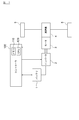
- FIG. 1 is a block diagram of a vehicle drive system according to the present embodiment.
- FIG. 2 is a block diagram of a drive system according to the present embodiment.
- FIG. 3 is a block diagram of the inverter control device according to the present embodiment.
- FIG. 4 is a graph showing the characteristics of the voltage command value (v p * ), the characteristics of the voltage command value (v q * ), the characteristics of the motor rotational speed, and the characteristics of the motor torque.
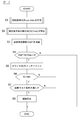
- FIG. 5 is a flowchart showing a control flow of the demagnetization determination by the controller shown in FIG.
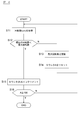
- FIG. 6 is a flowchart showing a control flow of step S1 in FIG.
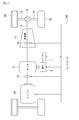
- FIG. 7 is a block diagram of a vehicle drive system according to another embodiment of the present invention.
- FIG. 1 is a block diagram of a vehicle drive system according to the present embodiment.
- FIG. 2 is a block diagram of a drive system according to the present embodiment.
- FIG. 3 is a block diagram of the invert
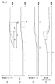
- FIG. 8 is a graph showing the characteristics of the engine rotation speed, the characteristics of the voltage command value (v q * ), the characteristics of the motor rotation speed, and the characteristics of the motor torque command value.
- FIG. 9 is a flowchart showing a control flow of the demagnetization determination by the controller.
- FIG. 10 is a graph showing the characteristics of the brake braking force, the voltage command value (v q * ), the characteristics of the motor rotational speed, the characteristics of the motor torque, and the vehicle speed characteristics.
- FIG. 11 is a flowchart showing a control flow of the demagnetization determination by the controller.
- FIG. 12 is a flowchart showing a control flow of the demagnetization determination by the controller.
- FIG. 1 is a block diagram showing a vehicle drive system including an inverter control device according to an embodiment of the present invention.
- the inverter control apparatus of this example is a hybrid vehicle equipped with at least a motor, such as a parallel hybrid vehicle and a series hybrid vehicle. It is applicable also to vehicles.
- a vehicle control stem including the inverter control device of the present example includes a battery 1, an inverter 2, a motor 3, a reduction gear 4, a drive wheel 5, and a controller 100.
- the vehicle drive system is not limited to the configuration shown in FIG. 1 and may have other configurations such as accessories.
- the battery 1 is a power source of a vehicle, and is a battery group in which a plurality of secondary batteries are connected in series or in parallel. A lithium ion battery or the like is used for the secondary battery.
- the inverter 2 includes a plurality of switching elements such as IGBTs, and switches the switching elements on and off according to a switching signal from the controller 100 to convert AC power output from the battery 1 into DC power. In addition, inverter 2 converts AC power generated by the regenerative operation of motor 3 into DC power, and outputs DC power to battery 1.
- a current sensor is connected between the inverter 2 and the motor 3. The current sensor detects the current flowing through the motor 3 and outputs a detected value to the controller 100.
- the motor 3 is a drive source of a vehicle which is connected to a drive shaft of the vehicle and driven by AC power from the inverter 2.
- the motor 3 is a motor such as a permanent magnet synchronous motor.
- a rotation angle sensor is connected to the motor 3, and a detected value of the rotation angle sensor is output to the controller 100.
- the output shaft of the motor 3 is connected to the left and right drive wheels 5 via the reduction gear 4 and the left and right drive shafts. Further, the motor 3 regenerates energy by generating regenerative driving force by the rotation of the driving wheel 5.
- the controller 100 responds to the driver's operation amount of the accelerator pedal, vehicle conditions such as accelerator opening, vehicle speed and gradient, SOC of the battery 1, chargeable / dischargeable power of the battery 1, generated power of the motor 3, etc.
- requirement is commanded to the inverter 2.
- FIG. The driver's request is determined by the accelerator operation and the brake operation.
- the controller 100 controls the motor 3 via the inverter 2 while optimizing the efficiency of the drive system of the vehicle according to the driving state of the vehicle and the state of the battery 1.
- the controller 100 may be a plurality of controllers such as a motor controller and an integrated controller.
- the various controllers are connected by a CAN communication network.
- the controller 100 includes a memory 110, a CPU 120, and the like.
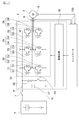
- FIG. 2 is a block diagram of a drive system.
- the inverter 2 includes upper arm elements 21, 23 and 25 forming an upper arm circuit, lower arm elements 22, 24 and 26 forming a lower knitting circuit, a smoothing capacitor 27, a discharge resistor 28, and a discharge switch 29. And a drive circuit 30.
- the upper arm elements 21, 23, 25 mainly have circuits in which switching elements Q1, Q3, Q5 as power devices and diodes D1, D3, D5 are respectively connected in parallel.
- the collector terminal of the switching element Q1 is connected to the cathode terminal of the diode D1, and the collector terminal of the switching element Q1 is connected to the anode terminal of the diode D1.
- Lower arm elements 22, 24, 26 mainly have a circuit in which switching elements Q2, Q4, Q6 as power devices and diodes D2, D4, D6 are respectively connected in parallel.
- the connection between the switching element Q2 to the switching element Q6 and the diodes D2 to D6 is similar to the connection between the switching element Q1 and the diode D1.
- three pairs of circuits in which two switching elements Q1 to Q6 are connected in series are electrically connected to the battery 1 by being connected between the power supply line P and the power supply line N, and each pair is connected The respective connection points connecting the switching elements of the above are electrically connected to the three-phase output parts of the three-phase motor 3 respectively.
- the power supply line P is connected to the positive electrode side of the battery 1
- the power supply line N is connected to the negative electrode side of the battery 1.
- connection point between the emitter terminal of switching element Q1 and the collector terminal of switching element Q2 is the output of the U phase
- the connection point between the emitter terminal of switching element Q3 and the collector terminal of switching element Q4 is the output of V phase
- the switching element A connection point between the emitter terminal of Q5 and the collector terminal of the switching element Q6 is a W-phase output, and is connected to the three-phase wiring of the motor 3.
- the upper arm elements 21, 23 and 25 and the lower arm elements 22, 24 and 26 constitute a two-level three-phase inverter circuit 20.
- the smoothing capacitor 27 is an element connected between the inverter circuit 20 and the battery 1 to smooth the power from the battery 1.
- the smoothing capacitor 27 is connected between the power supply lines P and N.
- the discharge resistor 28 and the discharge switch 29 are connected in series, and a series circuit of the discharge resistor 28 and the discharge switch 29 is connected between the power supply lines P and N.
- the discharge resistor 28 discharges the charge stored in the smoothing capacitor 27.
- the controller 100 controls the on / off of the discharge switch 29. When the discharging switch 29 is turned on, the smoothing capacitor 27 and the discharging resistor 28 are brought into conduction to perform discharging.
- the drive circuit 30 has a function of switching on and off the switching elements S1 to S6 based on a switching signal transmitted from the controller 100.
- the motor 3 is connected to the connection point of the switching elements Q1 and Q2, the connection point of the switching elements Q3 and Q4, and the connection point of the switching elements Q5 and Q6 in each phase of the inverter circuit.
- the relay switch 7 is connected between the battery 1 and the smoothing capacitor 27 of the inverter 2.
- the controller 100 is a controller for controlling the drive circuit 30.
- the controller 100 of the inverter 2 for outputting the required torque of the torque command value from the motor 3 based on the torque command value input from the outside, the phase current of the motor 3 and the rotational speed (rotational speed) of the motor 3 Calculate the current command value.
- the phase current of the motor 3 is detected by a current sensor 8 connected between the inverter circuit 20 and the motor 3, and the rotational speed of the motor 3 is calculated from the detection value of the resolver 9 provided in the motor 3. Ru.
- the controller 100 generates a switching signal for supplying the power required by the motor 3 and outputs the generated switching signal to the drive circuit 30. Then, the drive circuit 30 switches on / off of the switching elements Q1 to Q6 based on the switching signal. Thus, the controller 100 controls the inverter 2 by PWM control.
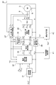
- FIG. 3 is a block diagram of the inverter 2, the motor 3, and the controller 100.
- the controller 100 includes a rotation number controller 31, a current command value calculator 32, a current controller 33, a non-interference controller 34, a two-phase three-phase voltage converter 35, a rotation number calculator 36, and a three-phase two-phase current converter It has 37.
- Rotational speed controller 31 matches the rotational speed detection value ( ⁇ G : motor rotational speed) output from rotational speed calculator 36 with the rotational speed command value ( ⁇ G * ) of motor 3 output from controller 100 It is a PID controller which calculates the torque command value (T * ) of the motor 3 so that The rotation speed controller 31 receives the rotation speed command value ( ⁇ G * ) and the rotation speed detection value ( ⁇ G ), calculates the torque command value (T * ) by the following equation (1), and calculates the current command value It is output to the computing unit 32.
- K p is a proportional gain
- K I is an integral gain
- K D is a differential gain
- T D is a time constant of approximate derivative
- s is a Laplace operator
- ⁇ G is a rotational speed detection value
- ⁇ G * indicates a rotational speed command value.
- the rotational speed command value ( ⁇ G * ) is a target value calculated by the controller 100.
- the controller 100 calculates the target torque according to the user's request according to the vehicle state, and calculates the number of rotations necessary to output the target torque as a rotation number command value.
- the current command value calculator 32 receives the torque command value (T * ), the voltage of the battery 1 (V dc ), and the rotational speed detection value ( ⁇ G ) indicating the angular frequency of the motor 3
- the dq axis current command values (I d * , I q * ) are calculated and output to the current controller 33.
- the dq axis represents the axis of the rotational coordinate system by the axis of the magnetic flux of the magnet and the axis orthogonal to the axis of the magnet.
- the current command value calculator 32 receives dq axis current command values (I d * , I q * ) using the torque command value (T * ), the rotational speed detection value ( ⁇ G ), and the voltage (V dc ) as indices.
- a map for output is stored in the memory 110. The map is an optimum command value that minimizes the loss of the motor 3 and the loss of the inverter 2 with respect to the torque command value (T * ), the rotational speed detection value ( ⁇ G ) and the voltage (V dc ) input. Are assigned to output. Then, the current command value calculator 32 calculates the dq axis current command values (I d * , I q * ) with reference to the map.
- the current command value calculator 32 In addition to the torque command value (T * ), the voltage (V dc ) of the battery 1 and the rotational speed detection value ( ⁇ G ), the current command value calculator 32 also calculates the dq axis current based on the detection value of the current sensor 8 (I d , I q ) and chargeable / dischargeable power (P in , P out ) of the battery 1 are input, and the current command value calculator 32 calculates a dq axis current command value.
- the dq axis current command value is a target value of the current of the motor 3 and includes an excitation current command value and a torque current command value.
- the current controller 33 performs control calculation using the following equation (2) with the dq axis current command values (I d * , I q * ) and the dq axis current (I d , I q ) as inputs.
- dq axis voltage command value (v d * , v q * ) is output.
- the dq-axis voltage command values (v d * , v q * ) are target values of the voltage of the motor 3 and include an excitation voltage command value and a torque voltage command value.
- K pd and K pq indicate proportional gains
- K id and K iq indicate integral gains.
- the current controller 33 may calculate the dq axis voltage command values (v d * , v q * ) with reference to the map corresponding to the equation (2).
- the non-interference controller 34 calculates dq-axis noninterference voltages (v ddcpl , v qdcpl ) for canceling the interference voltage generated when current flows in the d-axis and q-axis of the motor 3.
- the voltage equation of the motor 3 is generally represented by the following equation (3) when represented by dq coordinates.
- L d is the d-axis inductance
- L q is the q-axis inductance
- R a is the winding resistance of the motor 3
- ⁇ re is the electrical angular velocity
- ⁇ a is the magnetic flux density (torque constant)
- p is the derivative Indicates an operator.
- the incoherence controller 34 As shown in equation (3), there is a velocity electromotive force that interferes with each other between the d and q axes, and in order to cancel this, the incoherence controller 34 generates an incoherent voltage (v Calculate ddcpl and v qdcpl ).
- a subtractor is provided on the output side of the current controller 33 and the non-interference controller 34.
- the non-interference voltage (v d * , v q * ) is expressed by the equation (6).
- the interference term of equation (4) is canceled, and the dq axis current is expressed by the following equation (7).
- the two-phase three-phase voltage converter 35 receives the dq-axis voltage command values (v d * , v q * ) and the detected value ⁇ of the resolver 9 as inputs and uses the following equation (8) to Converts dq axis voltage command values (v d * , v q * ) into voltage command values (v u * , v v * , v w * ) of u, v and w axes in the fixed coordinate system, and outputs them to inverter 2 Do.
- the three-phase to two-phase current converter 37 is a control unit that performs three-phase to two-phase conversion, and receives fixed phase coordinates (I u , I v , I w ) and a detection value ⁇ of the magnetic pole position detector 52 as fixed coordinates.
- the phase current (I u , I v , I w ) of the system is converted to the phase current (I d , I q ) of the rotating coordinate system, and the current command value calculator 32, the current controller 33 and the non-interference controller 34 Output.
- the current sensor 8 is provided to each of the U phase and the V phase, detects a phase current (I u , I v ), and outputs the phase current to the three-phase two-phase current converter 37.
- the current of the w phase is not detected by the current sensor 8. Instead, the three-phase to two-phase current converter 37 calculates the phase current of the w phase based on the input phase current (I u , I v ) .
- the resolver (rotation sensor) 9 is provided in the motor 3 and is a detector that detects the position of the magnetic pole of the motor 3, and outputs a detected value ( ⁇ ) to the rotation number calculator 36.
- the resolver 9 detects the rotational state of the motor 3 at a predetermined cycle.
- the rotation speed calculator 36 calculates the rotation speed detection value ( ⁇ G ) which is the angular frequency of the motor 3 from the detection value ( ⁇ ) of the resolver 9 and outputs it to the rotation speed controller 31 and the current command value calculator 32. .
- phase current (I d , I q ) is input to the current controller 33, whereby the control device is controlled by the current control loop of a predetermined gain.
- the inverter 2 also generates a PWM control signal that switches on and off of the switching element based on the input voltage command values (v * u , v * v , v * w ) under control of the current control loop, The switching element is operated based on the PWM control signal to convert power.
- the determination threshold calculator 41 calculates a determination threshold (v qd * ) for determining demagnetization.
- the demagnetization determiner 42 compares the voltage command value (v q * ) with the determination threshold (v qd * ), and based on the comparison result, whether or not demagnetization of the magnet included in the motor 3 has occurred. Determine The determination of the demagnetization by the determination threshold calculator 41 and the demagnetization determiner 42 will be described later.
- a strong magnet such as a neodymium magnet is used.
- this magnet is magnetized to obtain a magnetic force, it can not hold the magnetic force if an excessive magnetic force is applied in the reverse direction. This phenomenon is demagnetization. Then, when demagnetization occurs in the motor for driving the vehicle, the torque of driving the vehicle decreases because the magnetic force of the motor is weak although current flows in the motor.
- the torque voltage (v q ) changes according to the number of rotations of the motor 3, so the voltage command value (v q * ) also changes according to the number of motor rotations.
- the number of revolutions of the motor fluctuates depending on the state of the vehicle, the driver's driving operation and the like, and is not steady. Therefore, the voltage command value (v q * ) is also not a steady value.
- the reduction of the voltage command value (v q * ) is caused not only by the demagnetization but also by the change of the motor rotational speed.
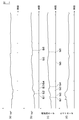
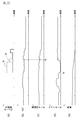
- FIG. 4 is a graph showing the characteristics of the voltage command value (v p * ), the characteristics of the voltage command value (v q * ), the characteristics of the motor rotational speed, and the characteristics of the motor torque.
- the horizontal axis shows time.
- the voltage command value (v q * ) changes so as to follow the motor rotational speed.
- the motor rotational speed changes in such a characteristic that it has either a maximum value or a minimum value at time t réelle 1 , t rion 2 , t réelle 3 , t réelle 4 , t rion 5 and t réelle 6
- the voltage command value (v q * changes in such a characteristic that it has either a maximum value or a minimum value at time t b1 , t b2 , t b3 , t b4 , t b5 and t b6 .
- time t réelle1 of the maximum point of the motor rotation speed corresponds to time t b1 of the maximum point of the voltage command value (v q * )
- time t réelle2 of the pole shop of the motor rotation speed is the voltage command value (v Times t réelle 3 , t réelle 4 , t réelle 5 and t rion 6 of the other maxima or minima of the motor rotational speed corresponding to the time t b 2 of the minimum of q * ) are other voltage command values (v q * )
- the demagnetization determination is performed under the state where the operating point of operation fluctuates, using the correlation between the voltage command value (v q * ) and the motor rotational speed.
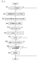
- FIG. 5 is a flowchart showing a control flow of the demagnetization determination by the controller 100.
- the control flow shown in FIG. 5 is repeatedly executed at a predetermined cycle.
- the control cycle of the control flow may be a cycle (for example, 10 ms) sufficiently small with respect to the time (corresponding to the driving cycle of the vehicle) in which the rotational speed changes.
- step S1 the demagnetization determiner 42 specifies a rotation speed maximum value ( ⁇ G MAX ) which is a maximum value of the motor rotation speed ( ⁇ G ).
- ⁇ G MAX a rotation speed maximum value of the motor rotation speed
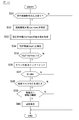
- FIG. 6 is a flowchart showing the control process of step S1.
- step S11 the demagnetization determiner 42 acquires the motor rotational speed ( ⁇ G ) from the rotational speed calculator 36.
- the demagnetization determiner 42 compares the current motor rotation number ( ⁇ G ) with the maximum rotation number.
- the current motor rotational speed ( ⁇ G ) is a value acquired in the control process of step S11.
- the initial value of the maximum rotational speed may be the motor rotational speed ( ⁇ G ) acquired first in the control flow shown in FIG.
- step S12 the demagnetization determiner 42 compares the current number of rotations with the maximum number of rotations. If the current rotational speed is equal to or greater than the maximum rotational speed, the process proceeds to step S13. If the current rotational speed is lower than the maximum rotational speed, the process proceeds to step S15. In step S13, the demagnetization determiner 42 updates the maximum number of rotations by setting the current number of rotations to a new maximum number of rotations. In step S14, the counter A is reset, and the process returns to step S11. That is, while the motor rotational speed is increasing, the demagnetization determiner 42 repeatedly executes the control loop from step S11 to step S14 to update the maximum rotational speed. Then, when the current rotation speed becomes lower than the updated maximum rotation speed, the process proceeds to step S15.
- step S15 the demagnetization determiner 42 increments the counter A.
- step S16 the demagnetization determiner 42 determines whether the counter A is 100 or more. If it is determined that the counter A is less than 100, the process returns to step S11. If it is determined that the counter A is 100 or more, the control flow shown in FIG. 6 is ended. In the case where the control process shown in FIG. 6 is performed, for example, every 10 ms, when the maximum rotation number is not updated while counting 100 times continuously after the current rotation number becomes lower than the maximum rotation number. The demagnetization determiner 42 determines that the local maximum value of the motor rotational speed has been acquired, and sets the current maximum rotational speed to the rotational speed maximum value ( ⁇ G MAX ).
- the demagnetization determiner 42 specifies the maximum value (v q * MAX ) of the voltage command value.
- the method of specifying the maximum value (v q * MAX ) of the voltage command value can be specified by executing a control flow in which the number of rotations is replaced with the voltage command value in the control flow shown in FIG.
- the determination threshold calculator 41 calculates a demagnetization determination threshold (v qd * ) according to the rotation speed maximum value ( ⁇ G MAX ).
- the demagnetization determination threshold (v qd * ) is a threshold for determining demagnetization, and is a value corresponding to the motor rotational speed ( ⁇ G ).
- the memory 110 stores a map in which the motor rotational speed ( ⁇ G ) and the demagnetization determination threshold (v qd * ) are associated with each other. That is, when the rotation speed maximum value ( ⁇ G MAX ) changes, the determination threshold (v qd * ) indicated by the map also becomes a different value. Then, the determination threshold calculator 41 specifies the determination threshold (v qd * ) corresponding to the rotation speed maximum value ( ⁇ G MAX ) on the map while referring to the map.
- step S4 the demagnetization determiner 42 determines the difference (v qd * -v q * ) between the determination threshold (v qd * ) specified on the map and the maximum value (v q * MAX ) of the voltage command value .
- MAX is calculated, and the calculated difference is compared with a predetermined threshold (D).
- the predetermined threshold (D) indicates a decrease amount of the voltage command value (v q * ) due to demagnetization, and is set in advance accordingly.
- the demagnetization determiner 42 determines that the maximum value (v q * MAX ) of the voltage command value is lower than the normal value, and proceeds to the control of step S5. On the other hand, if the difference is less than the threshold (D), the demagnetization determiner 42 determines that demagnetization has not occurred and is normal, and terminates the control flow shown in FIG.
- step S5 the demagnetization determiner 42 increments the counter (B).
- step S6 the demagnetization determiner 42 compares the counter (B) with the threshold (B th ).
- the threshold (B th ) indicates the number of determinations determined to be abnormal, and is determined according to the determination accuracy of the demagnetization.
- the threshold (B th ) is determined in advance, and is set to, for example, three times.
- the demagnetization determiner 42 determines whether the diagnostic mask condition is satisfied.
- the diagnostic mask conditions are conditions for determining whether the calculated value (corresponding to the detection value of the resolver 9) of the motor rotational speed used for the demagnetization diagnosis is a value suitable for the diagnosis.
- no abnormality in the current sensor 8 or no abnormality in the CPU included in the controller 100 is an example of the diagnostic mask condition.
- the calculated value of the motor rotational speed may be lower than the actual rotational speed. Therefore, when it is determined that the diagnostic mask condition is not satisfied, the demagnetization determiner 42 ends the control flow shown in FIG.
- the demagnetization determiner 42 determines in step S8 that the demagnetization occurs.
- the controller 100 notifies the driver of the occurrence of demagnetization.
- the voltage command for controlling the voltage of the motor 3 based on the torque command value, the detected value of the rotation state detected by the resolver 9, and the detected current detected by the current sensor 8 by the controller 100 A value is calculated, the maximum value of the torque voltage command value included in the voltage command value is specified as the determination target command value, the determination target command value is compared with the demagnetization determination threshold, and the magnet is reduced according to the comparison result. It is determined whether or not magnetism has occurred. Thereby, demagnetization can be determined even when the operating point of the motor 3 fluctuates.
- a state in which the reverse magnetic field exceeds the knick point is a state of demagnetization. Then, when the reverse magnetic field exceeds the knick point, the magnetic force sharply decreases, and the degree of decrease in rotational speed is large.
- the effect of the demagnetization is the voltage when the demagnetization exceeding the knick point occurs. It appears in the change of the maximum value of the command value (v q * ).
- occurrence of demagnetization can be diagnosed with high accuracy in a system such as a vehicle drive system in which the motor rotational speed changes.
- the motor rotation number corresponding to the maximum value of the voltage command value (v q * ) is acquired, and the demagnetization determination threshold is set based on the acquired motor rotation number. Thereby, the accuracy of the demagnetization determination can be enhanced.
- the local minimum value of the motor rotational speed may be used instead of the local maximum value of the motor rotational speed.
- the rotation speed minimum value ( ⁇ G MIN ) is specified.
- the minimum value (v q * MIN ) of the voltage command value is specified.
- the method of specifying the minimum number of revolutions ( ⁇ G MIN ) or the minimum (v q * MIN ) of the voltage command value is the maximum motor revolution number or the minimum motor revolution number or minimum voltage command
- the magnitude of the determination flow in step S12 may be reversed. Then, the demagnetization diagnosis may be performed by executing the same control as step S3 and subsequent steps shown in FIG.
- the controller 100 specifies the minimum value of the torque voltage command value included in the voltage command value as the determination target command value, and compares the determination target command value with the demagnetization determination threshold value. It is determined according to whether or not demagnetization of the magnet is occurring. Thereby, demagnetization can be determined even when the operating point of the motor 3 fluctuates.
- an average value of the motor rotational speed may be used instead of the maximum value of the motor rotational speed.
- the rotation speed average value ( ⁇ G AVE ) is specified in the control flow of step S1 shown in FIG. 5.
- an average value (v q * AVE ) of voltage command values is specified in the control flow of step S2.
- the rotation speed average value ( ⁇ G AVE ) specifies the rotation speed maximum value ( ⁇ G MAX ) and the rotation speed minimum value ( ⁇ G MIN ) in the same manner as above, and calculates the average value of these two values do it.
- the average value (v q * AVE ) of the voltage command value specifies the maximum value (v q * MAX ) of the voltage command value and the minimum value (v q * MIN ) of the voltage command value in the same manner as above. And calculate the average value of these two values. Then, the demagnetization diagnosis may be performed by executing the same control as step S3 and subsequent steps shown in FIG.
- the controller 100 specifies the average value of the torque voltage command values included in the voltage command value as the determination target command value, compares the determination target command value with the demagnetization determination threshold, and compares the result. It is determined according to whether or not demagnetization of the magnet is occurring. Thereby, demagnetization can be determined even when the operating point of the motor 3 fluctuates.
- the determination threshold calculator 41 may calculate, for example, a moving average value of the torque voltage command value (v q * ) as the determination threshold (v qd * ) instead of the calculation processing using the map.
- the determination threshold calculator 41 may calculate the determination threshold (v qd * ) by arithmetic processing using an arithmetic expression including at least the motor rotational speed as a variable, not limited to the moving average.
- FIG. 7 is a block diagram of a vehicle drive system according to the present embodiment.
- the inverter control device according to the present embodiment is applied to a vehicle drive system shown in FIG.
- a hybrid vehicle is a parallel type automobile using a plurality of power sources such as an internal combustion engine and a motor generator for driving the vehicle, and a battery 1, an inverter 2, a motor 3, left and right driving wheels 5, an internal combustion engine (hereinafter referred to as an engine)
- a first clutch 11, a second clutch 12, a propeller shaft 13, a differential gear unit 14, a drive shaft 15, and an automatic transmission 17 are provided.
- the first clutch 11 is interposed between the output shaft of the engine 10 and the rotation shaft of the motor 3 to connect / disconnect (ON / OFF) power transmission between the engine 10 and the motor 3.
- the wet multi-disc clutch etc. which can control oil flow and oil pressure continuously with a proportional solenoid can be illustrated.
- the hydraulic pressure of the hydraulic unit is controlled based on a control signal from the controller 100, whereby the clutch plate of the first clutch 11 is engaged (including a slip state) or released.
- a dry clutch may be adopted as the first clutch 11.
- the automatic transmission 17 is a stepped transmission that changes the gear ratio stepwise such as seven forward gears and one reverse gear, and switches the gear ratio automatically according to the vehicle speed, the accelerator opening degree, and the like.
- the second clutch 12 can use some of the plurality of friction coupling elements that are engaged at each shift position of the automatic transmission 17 and that use some of the friction coupling elements. Also, instead of this, a dedicated clutch other than the second clutch 7 may be used.
- the output shaft of the automatic transmission 17 is connected to the left and right drive wheels 5 via the propeller shaft 13, the differential gear unit 14, and the left and right drive shafts 15.
- reference numeral 5 denotes left and right steered front wheels.
- the controller 100 connects the clutch 12 and rotates the drive wheels 5 with the driving force of the motor 3 to drive the vehicle. Further, for example, when the output of the engine 10 is required by the operation of the driver, the controller 100 connects the clutch 11 and starts the engine by the driving force of the motor 3. At this time, if demagnetization occurs in the magnet included in the motor 3, the appropriate torque is not output from the motor 3 even if current flows to the motor 3, so the engine 10 does not start. In order to start the engine 10, it is necessary to increase the current of the motor 3 to increase the output torque of the motor 3, so the start time of the engine is extended.
- FIG. 8 is a graph showing the characteristics of the engine rotation speed, the characteristics of the voltage command value (v q * ), the characteristics of the motor rotation speed, and the characteristics of the motor torque command value.
- the horizontal axis shows time.
- the solid line shows the characteristics at the normal time, and the dotted line shows the characteristics at the time of demagnetization.
- controller 100 raises the torque command value to start the engine.
- the torque command value rises, the motor rotational speed increases, the voltage command value (v q * ) increases, and the engine rotational speed also increases.
- the rise of the engine speed starts at time t e1 , and complete explosion occurs at time t e2 .
- the engine start time is t p .
- the motor rotational speed does not increase significantly even if the motor torque command value is increased, so the motor torque command value is further increased.
- Engine speed is gradually increased from the point of time t e1, it takes time to increase in the engine speed, the state of complete explosion at time t e3.
- the engine start time is t q (> t p ). That is, when demagnetization occurs, the start time of the engine becomes long.
- the time t A of the maximum point of the motor rotational speed corresponds to the time t b the maximum point of the voltage command values (v q *), the voltage command value (v q *) follows the motor speed It has changed.
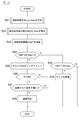
- the condition for engine start time is added to the demagnetization determination logic in the following control flow.
- step S21 the controller 100 determines whether there is a request for starting the engine. For example, when there is an acceleration request due to an accelerator operation and an engine output is required, the controller 100 determines that the engine start request is present. The controller 100 also raises a torque command value to start the engine. The controller 100 starts measuring the engine start time. The controller 100 detects the number of revolutions of the engine using an engine revolution number sensor (not shown) after raising the torque command value. Then, the time from when the engine rotation starts to when the detected engine speed reaches the speed threshold indicating complete explosion is measured as the engine start time.
- step S22 to step S28 is the same as the control process from step S1 to step S7 shown in FIG.
- step S29 the controller 100 determines whether the engine start time is longer than a predetermined time threshold.
- the predetermined time threshold is set in advance, and is set to a time longer than the engine start time when demagnetization does not occur.
- step S30 the demagnetization determiner 42 determines that demagnetization is occurring. If it is determined that the engine start time is equal to or less than the time threshold, the demagnetization determiner 42 determines that demagnetization has not occurred, and terminates the control flow.
- the start time of the engine 10 connected to the motor 3 is measured, and it is determined based on the start time whether or not demagnetization of the magnet is occurring. Thereby, the accuracy of the demagnetization determination can be enhanced.
- condition of the engine start time is added to the demagnetization determination logic, so the magnitude of the predetermined threshold (D) is smaller than the value (D) set in the first embodiment.
- FIG. 7 exemplifies a rear wheel drive hybrid vehicle, it is also possible to use a front wheel drive hybrid vehicle or a four wheel drive hybrid vehicle.
- the hybrid system may be a series type.
- the present embodiment differs from the first embodiment in that a control flow for demagnetization determination is partially added.
- the other configuration and control method are the same as those of the first embodiment described above, and the descriptions of the first embodiment and the second embodiment are incorporated as appropriate.
- FIG. 10 is a graph showing the characteristics of the brake braking force, the voltage command value (v q * ), the characteristics of the motor rotational speed, the characteristics of the motor torque, and the vehicle speed characteristics.
- the horizontal axis shows time.
- the solid line shows the characteristics at the normal time, and the dotted line shows the characteristics at the time of demagnetization.
- the driver performs a brake operation at time t p.
- the signal of the brake switch changes from the low level to the high level, and control for deceleration is started.
- the controller 100 receives a regeneration control command from the host controller, generates regenerative torque to the motor 3, and recovers kinetic energy at the time of deceleration of the vehicle.
- the motor 3 can generate a normal regenerative braking force.
- the braking force of the brake (mechanical brake) is a braking force obtained by subtracting the regenerative braking force of the motor 3 from the braking force for the deceleration request. Therefore, when the motor 3 is normal, the braking force of the brake is small (see the graph a in FIG. 10).
- the condition of the braking force is added to the demagnetization determination logic in the following control flow.
- step S31 the controller determines whether or not there is an input of a regeneration control command. If it is determined that the regeneration control command is input, the process proceeds to step S32. If it is determined that there is no regenerative control command input, the control flow is ended.
- step S32 to step S38 is the same as the control process from step S1 to step S7 shown in FIG.
- step S39 the controller 100 determines whether the braking force of the brake is greater than a preset braking force threshold.
- the demagnetization determiner 42 determines that demagnetization is occurring. If it is determined that the braking force of the brake is equal to or less than the braking force threshold, the demagnetization determiner 42 determines that demagnetization has not occurred, and terminates the control flow.
- the present embodiment it is determined whether or not demagnetization of the magnet is occurring, based on the braking force of the brake when the vehicle speed changes. Thereby, the accuracy of the demagnetization determination can be enhanced.
- a torque command value when the vehicle speed decreases may be added to the determination logic of the demagnetization. As shown in FIG. 10 (d), when the motor 3 is regenerated, when demagnetization occurs, the torque command value in the regeneration direction becomes lower than that in the normal state, so demagnetization is performed based on the torque command value. Can be determined.
- controller 100 determines whether or not the torque command value is smaller than a preset torque command value threshold value in the control process of step S39 shown in FIG. If the torque command value is smaller than the torque command value threshold, the controller 100 determines that demagnetization is occurring. On the other hand, when the torque command value is equal to or greater than the torque command value threshold value, the controller 100 determines that demagnetization has not occurred, and terminates the control flow.
- a torque command value when the vehicle speed is increased may be added to the determination logic of the demagnetization.
- the torque command value in the power running direction is lower than that in the normal state, so that demagnetization can be determined based on the torque command value.
- the controller 100 calculates the torque voltage command value (v q * ) based on the motor rotation speed ( ⁇ G ) at a predetermined cycle, and corresponds the motor rotation speed ( ⁇ G ) to the torque voltage command value (v q * ) Then, it is stored in the memory 110 as a map. The controller 100, the current motor speed (omega G) to the newly torque voltage command value based (v q *) when calculating the current motor speed torque voltage command value corresponding to the ( ⁇ G) (v Identify q * ) on the map.
- Controller 100 a torque voltage command value specified on the map (v q *) and the newly computed torque voltage command value (v q *) is compared with the smaller torque voltage command values (v q * ) Is set as a new determination threshold (v qd * ).
- the controller 100 associates the newly set determination threshold (v qd * ) with the motor rotational speed ( ⁇ G ) and stores the result in the map.
- the controller 100 if the newly computed torque voltage command value (v q *), a torque voltage command value stored as a map on a determination threshold value (v qd *) and (v q *), a new taking the select-low of the computed torque voltage command value (v q *), the set more lower torque voltage command values (v q *) the determination threshold (v qd *), and updates the map.
- FIG. 12 is a flowchart showing a control flow of the controller 100.
- the control flow of steps S41 to S48 is the same as the control flow of steps S1 to S8 according to the first embodiment, and therefore the description will be omitted.
- step S44 when the difference (v qd * -v q * MAX ) from the maximum value (v q * MAX ) of the voltage command value is equal to or less than the threshold (D), controller 100 performs step S49. While referring to the map, the determination threshold (v qd * ) corresponding to the current motor rotational speed is specified. The controller 100 compares the specified determination threshold (v qd * ) with the maximum value (v q * MAX ) of the current voltage command value.
- the controller 100 determines the local maximum value (v The map is updated by newly setting q * MAX ) to the determination threshold (v qd * ).
- the controller 100 ends the control flow without updating the map. .
- the rotational state of the motor 3 detected by the resolver 9 and the calculated torque voltage command value (v q * ) are stored in the memory 110 in correspondence with each other, to the current rotational state.
- based torque voltage command value (v q *) is newly computed, the newly computed torque voltage command value (v q *) with the stored torque voltage command value to the memory 110 (v q *) and of The lower value is set as the determination threshold (v qd * ).
- the determination threshold (v qd * ) is updated while managing the decrease of the torque voltage command value (v q * ) due to the individual variation of the inverter 2 or motor 3, the variation of the temperature characteristic of the inverter 2 or motor 3, etc. Therefore, the determination accuracy can be enhanced.
- Rotational speed controller 32 Current command value calculator 33 Current controller 34 Non-interference controller 35 Two-phase three-phase voltage converter 36 Number-of-rotations calculator 37 Three-phase two-phase current converter 41 Judgment threshold Arithmetic unit 42 ... Demagnetization determination unit 50 ... Clutch 52 ... Magnetic pole position detector 70 ... Continuously variable transmission 100 ... Controller 110 ... Memory 120 ... CP
Abstract
This inverter control method for driving a motor including a magnet includes: detecting the rotational state of the motor by a rotation sensor; detecting the current of the motor by a current sensor; calculating, by a controller for controlling an inverter, on the basis of a torque command value, the detection value of the rotational state detected by the rotation sensor, and the detection current detected by the current sensor, a voltage command value for controlling the voltage of the motor; specifying, by the controller, as a command value to be determined, at least either one of a maximal value, a minimal value, and an average value of a torque voltage command value included in the voltage command value; and comparing, by the controller, the command value to be determined with a demagnetization determination threshold value to determine according to the comparison result whether the demagnetization of the magnet occurs or not.
Description
本発明は、インバータ制御方法及びインバータ制御装置に関するものである。
The present invention relates to an inverter control method and an inverter control device.
電圧指令値Vqが所定のしきい値より低下したか否かを判定し、低下した場合にはさらにVqの挙動を監視し、Vqが定常的であればモータの減磁であると識別するモータ制御装置が知られている(特許文献1)。
A motor that determines whether or not the voltage command value Vq has fallen below a predetermined threshold value, and further monitors the behavior of Vq if it falls, and identifies the motor demagnetization if Vq is steady. A control device is known (Patent Document 1).
しかしながら、運転の動作点が変化する場合には、減磁を精度よく判定できないという問題があった。
However, when the operating point of driving changes, there is a problem that demagnetization can not be determined accurately.
本発明が解決しようとする課題は、運転の動作点が変動する場合でも減磁を判定できるインバータ制御装置及び車両駆動システムを提供することである。
The problem to be solved by the present invention is to provide an inverter control device and a vehicle drive system that can determine demagnetization even when the operating point of driving changes.
本発明は、電圧指令値に含まれるトルク電圧指令値の極大値、極小値及び平均値のうち少なくともいずれか一つの値を判定対象指令値として特定し、判定対象指令値と前記減磁判定閾値とを比較し、比較結果に応じて、磁石の減磁が発生しているか否かを判定することによって上記課題を解決する。
The present invention identifies at least one of the maximum value, the minimum value, and the average value of the torque voltage command value included in the voltage command value as the determination target command value, and determines the determination target command value and the demagnetization determination threshold value. And the above-mentioned problem is determined by determining whether or not demagnetization of the magnet is occurring according to the comparison result.
本発明によれば、運転の動作点が変動する場合でも減磁を判定できるという効果を奏する。
According to the present invention, it is possible to determine the demagnetization even when the operating point of driving changes.
以下、本発明の実施形態を図面に基づいて説明する。
Hereinafter, embodiments of the present invention will be described based on the drawings.
《第1実施形態》
図1は、本発明の実施形態に係るインバータ制御装置を含む車両駆動システムを示すブロック図である。以下、本例のインバータ制御装置を電気自動車に提供した例を挙げて説明するが、本例のインバータ制御装置は、例えばパラレル型のハイブリッド車両及びシリーズ型のハイブリッド車両等、少なくともモータを備えたハイブリッド車両にも適用可能である。 First Embodiment
FIG. 1 is a block diagram showing a vehicle drive system including an inverter control device according to an embodiment of the present invention. Hereinafter, although the example which provided the inverter control apparatus of this example to an electric vehicle is demonstrated, the inverter control apparatus of this example is a hybrid vehicle equipped with at least a motor, such as a parallel hybrid vehicle and a series hybrid vehicle. It is applicable also to vehicles.
図1に示すように、本例のインバータ制御装置を含む車両制御ステムは、バッテリ1と、インバータ2と、モータ3と、減速機4と、駆動輪5と、コントローラ100を備えている。なお、車両駆動システムは、図1に示す構成に限らず、補器類など他の構成を備えてもよい。
As shown in FIG. 1, a vehicle control stem including the inverter control device of the present example includes a battery 1, an inverter 2, a motor 3, a reduction gear 4, a drive wheel 5, and a controller 100. The vehicle drive system is not limited to the configuration shown in FIG. 1 and may have other configurations such as accessories.
バッテリ1は、車両の電力源であり、複数の二次電池を直列又は並列に接続した電池群である。二次電池には、リチウムイオン電池等が使用される。インバータ2は、IGBT等のスイッチング素子を複数備え、コントローラ100からのスイッチング信号により当該スイッチング素子のオン及びオフを切り替えることで、バッテリ1から出力される交流電力を直流電力に変換する。また、インバータ2は、モータ3の回生動作により発生した交流電力を直流電力に変換し、直流電力をバッテリ1に出力する。インバータ2及びモータ3の間には、電流センサが接続されている。電流センサは、モータ3に流れる電流を検出し、検出値をコントローラ100に出力する。
The battery 1 is a power source of a vehicle, and is a battery group in which a plurality of secondary batteries are connected in series or in parallel. A lithium ion battery or the like is used for the secondary battery. The inverter 2 includes a plurality of switching elements such as IGBTs, and switches the switching elements on and off according to a switching signal from the controller 100 to convert AC power output from the battery 1 into DC power. In addition, inverter 2 converts AC power generated by the regenerative operation of motor 3 into DC power, and outputs DC power to battery 1. A current sensor is connected between the inverter 2 and the motor 3. The current sensor detects the current flowing through the motor 3 and outputs a detected value to the controller 100.
モータ3は、車両の駆動軸に連結され、インバータ2からの交流電力により駆動する車両の駆動源である。モータ3は、永久磁石同期電動機等の電動機である。またモータ3には、回転角センサが接続され、当該回転角センサの検出値はコントローラ100に出力される。モータ3の出力軸は、減速機4及び左右のドライブシャフトを介して、左右の駆動輪5に連結されている。またモータ3は、駆動輪5の回転により、回生駆動力を発生させることで、エネルギを回生する。
The motor 3 is a drive source of a vehicle which is connected to a drive shaft of the vehicle and driven by AC power from the inverter 2. The motor 3 is a motor such as a permanent magnet synchronous motor. Further, a rotation angle sensor is connected to the motor 3, and a detected value of the rotation angle sensor is output to the controller 100. The output shaft of the motor 3 is connected to the left and right drive wheels 5 via the reduction gear 4 and the left and right drive shafts. Further, the motor 3 regenerates energy by generating regenerative driving force by the rotation of the driving wheel 5.
コントローラ100は、運転者のアクセルペダルの操作量に応じてアクセル開度、車速及び勾配などの車両状態、バッテリ1のSOC、バッテリ1の充放電可能電力、モータ3の発電電力等に応じて、運転者の要求に応じてトルクを出力させるための駆動トルク(必要トルク)を、インバータ2に指令する。運転者の要求は、アクセル操作、ブレーキ操作により決まる。
The controller 100 responds to the driver's operation amount of the accelerator pedal, vehicle conditions such as accelerator opening, vehicle speed and gradient, SOC of the battery 1, chargeable / dischargeable power of the battery 1, generated power of the motor 3, etc. The drive torque (required torque) for outputting a torque according to a driver | operator's request | requirement is commanded to the inverter 2. FIG. The driver's request is determined by the accelerator operation and the brake operation.
コントローラ100は、車両の運転状態及びバッテリ1の状態に応じて、車両の駆動系の効率を最適化しつつ、インバータ2を介してモータ3を制御する。なお、図1では、車両を制御する制御部分として、1つのコントローラ100が図示されているが、コントローラ100は、モータコントローラ、統合コントローラ等の複数のコントローラとしてもよい。各種コントローラは、CAN通信網で接続されている。コントローラ100は、メモリ110、CPU120等を有している。
The controller 100 controls the motor 3 via the inverter 2 while optimizing the efficiency of the drive system of the vehicle according to the driving state of the vehicle and the state of the battery 1. Although one controller 100 is illustrated in FIG. 1 as a control unit for controlling a vehicle, the controller 100 may be a plurality of controllers such as a motor controller and an integrated controller. The various controllers are connected by a CAN communication network. The controller 100 includes a memory 110, a CPU 120, and the like.
次に、車両の駆動システムについて、図2を用いて説明する。図2は、駆動システムのブロック図である。
Next, a drive system of the vehicle will be described with reference to FIG. FIG. 2 is a block diagram of a drive system.
インバータ2は、上アーム回路を形成する上アーム素子21、23、25と、下編む回路を形成する下アーム素子22、24、26と、平滑コンデンサ27と、放電抵抗28と、放電用スイッチ29と、駆動回路30とを有している。
The inverter 2 includes upper arm elements 21, 23 and 25 forming an upper arm circuit, lower arm elements 22, 24 and 26 forming a lower knitting circuit, a smoothing capacitor 27, a discharge resistor 28, and a discharge switch 29. And a drive circuit 30.
上アーム素子21、23、25は、パワーデバイスとしてのスイッチング素子Q1、Q3、Q5とダイオードD1、D3、D5とをそれぞれ並列に接続した回路を主要な構成としている。スイッチング素子Q1のコレクタ端子とダイオードD1のカソード端子が接続され、かつスイッチング素子Q1のコレクタ端子とダイオードD1のアノード端子が接続されている。下アーム素子22、24、26は、同じくパワーデバイスとしてのスイッチング素子Q2、Q4、Q6とダイオードD2、D4、D6とをそれぞれ並列に接続した回路を主要な構成とする。スイッチング素子Q2~スイッチング素子Q6とダイオードD2~D6の接続は、スイッチング素子Q1とダイオードD1の接続と同様である。
The upper arm elements 21, 23, 25 mainly have circuits in which switching elements Q1, Q3, Q5 as power devices and diodes D1, D3, D5 are respectively connected in parallel. The collector terminal of the switching element Q1 is connected to the cathode terminal of the diode D1, and the collector terminal of the switching element Q1 is connected to the anode terminal of the diode D1. Lower arm elements 22, 24, 26 mainly have a circuit in which switching elements Q2, Q4, Q6 as power devices and diodes D2, D4, D6 are respectively connected in parallel. The connection between the switching element Q2 to the switching element Q6 and the diodes D2 to D6 is similar to the connection between the switching element Q1 and the diode D1.
本実施形態では、2つのスイッチング素子Q1~Q6を直列に接続した3対の回路が、電源線Pと電源線Nの間に接続されることにより、バッテリ1に電気的に接続され、各対のスイッチング素子を接続する各接続点と、3相モータ3の三相の出力部とがそれぞれ電気的に接続されている。電源線Pはバッテリ1の正極側に接続され、電源線Nはバッテリ1の負極側に接続されている。
In this embodiment, three pairs of circuits in which two switching elements Q1 to Q6 are connected in series are electrically connected to the battery 1 by being connected between the power supply line P and the power supply line N, and each pair is connected The respective connection points connecting the switching elements of the above are electrically connected to the three-phase output parts of the three-phase motor 3 respectively. The power supply line P is connected to the positive electrode side of the battery 1, and the power supply line N is connected to the negative electrode side of the battery 1.
スイッチング素子Q1のエミッタ端子とスイッチング素子Q2のコレクタ端子との接続点はU相の出力となり、スイッチング素子Q3のエミッタ端子とスイッチング素子Q4のコレクタ端子との接続点はV相の出力となり、スイッチング素子Q5のエミッタ端子とスイッチング素子Q6のコレクタ端子との接続点はW相の出力となり、モータ3の三相配線に接続されている。そして、上アーム素子21、23、25及び下アーム素子22、24、26により2レベルの3相インバータ回路20が構成されている。
The connection point between the emitter terminal of switching element Q1 and the collector terminal of switching element Q2 is the output of the U phase, the connection point between the emitter terminal of switching element Q3 and the collector terminal of switching element Q4 is the output of V phase, and the switching element A connection point between the emitter terminal of Q5 and the collector terminal of the switching element Q6 is a W-phase output, and is connected to the three-phase wiring of the motor 3. The upper arm elements 21, 23 and 25 and the lower arm elements 22, 24 and 26 constitute a two-level three-phase inverter circuit 20.
平滑コンデンサ27は、インバータ回路20と、バッテリ1との間に接続される、バッテリ1からの電力を平滑する素子である。平滑コンデンサ27は、電源線P、N間に接続されている。
The smoothing capacitor 27 is an element connected between the inverter circuit 20 and the battery 1 to smooth the power from the battery 1. The smoothing capacitor 27 is connected between the power supply lines P and N.
放電抵抗28及び放電用スイッチ29は直列に接続され、放電抵抗28及び放電用スイッチ29の直列回路は、電源線P、N間に接続されている。放電抵抗28は、平滑コンデンサ27にチャージされた電荷を放電する。コントローラ100は、放電用スイッチ29のオン、オフを制御する。放電用スイッチ29がオンになると、平滑コンデンサ27と放電抵抗28が導通し、放電が行われる。
The discharge resistor 28 and the discharge switch 29 are connected in series, and a series circuit of the discharge resistor 28 and the discharge switch 29 is connected between the power supply lines P and N. The discharge resistor 28 discharges the charge stored in the smoothing capacitor 27. The controller 100 controls the on / off of the discharge switch 29. When the discharging switch 29 is turned on, the smoothing capacitor 27 and the discharging resistor 28 are brought into conduction to perform discharging.
駆動回路30は、コントローラ100から送信されるスイッチング信号に基づいて、スイッチング素子S1~S6のオン及びオフを切り替える機能を備えている。
The drive circuit 30 has a function of switching on and off the switching elements S1 to S6 based on a switching signal transmitted from the controller 100.
モータ3は、インバータ回路の各相で、スイッチング素子Q1、Q2の接続点、スイッチング素子Q3、Q4の接続点及びスイッチング素子Q5、Q6の接続点にそれぞれ接続されている。
The motor 3 is connected to the connection point of the switching elements Q1 and Q2, the connection point of the switching elements Q3 and Q4, and the connection point of the switching elements Q5 and Q6 in each phase of the inverter circuit.
リレースイッチ7は、バッテリ1とインバータ2の平滑コンデンサ27との間に接続されている。
The relay switch 7 is connected between the battery 1 and the smoothing capacitor 27 of the inverter 2.
コントローラ100は、駆動回路30を制御するためのコントローラである。コントローラ100は、外部から入力されるトルク指令値、モータ3の相電流、モータ3の回転数(回転速度)に基づいて、トルク指令値の要求トルクをモータ3から出力させるための、インバータ2の電流指令値を演算する。なお、モータ3の相電流は、インバータ回路20とモータ3との間に接続された電流センサ8により検出され、モータ3の回転速度は、モータ3に設けられたレゾルバ9の検出値から算出される。
The controller 100 is a controller for controlling the drive circuit 30. The controller 100 of the inverter 2 for outputting the required torque of the torque command value from the motor 3 based on the torque command value input from the outside, the phase current of the motor 3 and the rotational speed (rotational speed) of the motor 3 Calculate the current command value. The phase current of the motor 3 is detected by a current sensor 8 connected between the inverter circuit 20 and the motor 3, and the rotational speed of the motor 3 is calculated from the detection value of the resolver 9 provided in the motor 3. Ru.
そして、コントローラ100は、モータ3が必要とする電力を供給するためのスイッチング信号を生成し、駆動回路30に出力する。そして、駆動回路30は当該スイッチング信号に基づいて、各スイッチング素子Q1~Q6のオン、オフを切り換える。これにより、コントローラ100は、インバータ2をPWM制御により制御している。
Then, the controller 100 generates a switching signal for supplying the power required by the motor 3 and outputs the generated switching signal to the drive circuit 30. Then, the drive circuit 30 switches on / off of the switching elements Q1 to Q6 based on the switching signal. Thus, the controller 100 controls the inverter 2 by PWM control.
次に、図3を用いて、コントローラ100のうちインバータの制御に係る制御ブロックを説明する。図3は、インバータ2、モータ3、及びコントローラ100のブロック図である。コントローラ100は、回転数制御器31、電流指令値演算器32、電流制御器33、非干渉制御器34、二相三相電圧変換器35、回転数演算器36及び三相二相電流変換器37を有している。
Next, a control block related to control of the inverter in the controller 100 will be described using FIG. 3. FIG. 3 is a block diagram of the inverter 2, the motor 3, and the controller 100. The controller 100 includes a rotation number controller 31, a current command value calculator 32, a current controller 33, a non-interference controller 34, a two-phase three-phase voltage converter 35, a rotation number calculator 36, and a three-phase two-phase current converter It has 37.
回転数制御器31は、回転数演算器36から出力される回転数検出値(ωG:モータ回転数)を、コントローラ100から出力されるモータ3の回転数指令値(ωG
*)に一致させるように、モータ3のトルク指令値(T*)を演算するPID制御器である。回転数制御器31は、回転数指令値(ωG
*)及び回転数検出値(ωG)を入力として、以下の式(1)によりトルク指令値(T*)を演算し、電流指令値演算器32に出力する。

ただし、Kpは比例ゲインを、KIは積分ゲインを、KDは微分ゲインを、TDは近似微分の時定数を、sはラプラス演算子を、ωGは回転数検出値を、ωG
*は回転数指令値を示す。回転数指令値(ωG
*)は、コントローラ100により演算される目標値である。コントローラ100は、ユーザの要求に応じた目標トルクを車両状態に応じて演算し、目標トルクを出力するために必要な回転数を、回転数指令値として演算している。
Rotational speed controller 31 matches the rotational speed detection value (ω G : motor rotational speed) output from rotational speed calculator 36 with the rotational speed command value (ω G * ) of motor 3 output from controller 100 It is a PID controller which calculates the torque command value (T * ) of the motor 3 so that The rotation speed controller 31 receives the rotation speed command value (ω G * ) and the rotation speed detection value (ω G ), calculates the torque command value (T * ) by the following equation (1), and calculates the current command value It is output to the computing unit 32.
Where K p is a proportional gain, K I is an integral gain, K D is a differential gain, T D is a time constant of approximate derivative, s is a Laplace operator, ω G is a rotational speed detection value, ω G * indicates a rotational speed command value. The rotational speed command value (ω G * ) is a target value calculated by the controller 100. The controller 100 calculates the target torque according to the user's request according to the vehicle state, and calculates the number of rotations necessary to output the target torque as a rotation number command value.
電流指令値演算器32は、トルク指令値(T*)、バッテリ1の電圧(Vdc)、及び、モータ3の角周波数を示す回転数検出値(ωG)を入力して、モータ3のdq軸電流指令値(Id
*、Iq
*)を演算し、電流制御器33に出力する。dq軸は、磁石の磁束の軸と、磁石の軸と直交する軸による回転座標系の軸を表している。電流指令値演算器32には、トルク指令値(T*)、回転数検出値(ωG)、電圧(Vdc)を指標として、dq軸電流指令値(Id
*、Iq
*)を出力するためのマップがメモリ110に格納されている。当該マップは、トルク指令値(T*)、回転数検出値(ωG)及び電圧(Vdc)の入力に対して、モータ3の損失及びインバータ2の損失を最小限に抑える最適な指令値を出力するよう対応づけられている。そして、電流指令値演算器32は、当該マップを参照して、dq軸電流指令値(Id
*、Iq
*)を演算する。
The current command value calculator 32 receives the torque command value (T * ), the voltage of the battery 1 (V dc ), and the rotational speed detection value (ω G ) indicating the angular frequency of the motor 3 The dq axis current command values (I d * , I q * ) are calculated and output to the current controller 33. The dq axis represents the axis of the rotational coordinate system by the axis of the magnetic flux of the magnet and the axis orthogonal to the axis of the magnet. The current command value calculator 32 receives dq axis current command values (I d * , I q * ) using the torque command value (T * ), the rotational speed detection value (ω G ), and the voltage (V dc ) as indices. A map for output is stored in the memory 110. The map is an optimum command value that minimizes the loss of the motor 3 and the loss of the inverter 2 with respect to the torque command value (T * ), the rotational speed detection value (ω G ) and the voltage (V dc ) input. Are assigned to output. Then, the current command value calculator 32 calculates the dq axis current command values (I d * , I q * ) with reference to the map.
また電流指令値演算器32には、トルク指令値(T*)、バッテリ1の電圧(Vdc)及び回転数検出値(ωG)の他に、電流センサ8の検出値に基づくdq軸電流(Id、Iq)及びバッテリ1の充放電可能電力(Pin、Pout)が入力され、電流指令値演算器32は、dq軸電流指令値を演算する。dq軸電流指令値は、モータ3の電流の目標値であって、励磁電流指令値及びトルク電流指令値を含む。
In addition to the torque command value (T * ), the voltage (V dc ) of the battery 1 and the rotational speed detection value (ω G ), the current command value calculator 32 also calculates the dq axis current based on the detection value of the current sensor 8 (I d , I q ) and chargeable / dischargeable power (P in , P out ) of the battery 1 are input, and the current command value calculator 32 calculates a dq axis current command value. The dq axis current command value is a target value of the current of the motor 3 and includes an excitation current command value and a torque current command value.
電流制御器33は、dq軸電流指令値(Id
*、Iq
*)及びdq軸電流(Id、Iq)を入力として、以下の式(2)を用いて、制御演算を行い、dq軸電圧指令値(vd
*、vq
*)を出力する。dq軸電圧指令値(vd
*、vq
*)は、モータ3の電圧の目標値であって、励磁電圧指令値及びトルク電圧指令値を含む。

ただし、Kpd、Kpqは比例ゲインを、Kid、Kiqは積分ゲインを示す。
The current controller 33 performs control calculation using the following equation (2) with the dq axis current command values (I d * , I q * ) and the dq axis current (I d , I q ) as inputs. dq axis voltage command value (v d * , v q * ) is output. The dq-axis voltage command values (v d * , v q * ) are target values of the voltage of the motor 3 and include an excitation voltage command value and a torque voltage command value.
Here, K pd and K pq indicate proportional gains, and K id and K iq indicate integral gains.
なお、電流制御器33は、上記式(2)に対応するマップを参照して、dq軸電圧指令値(vd
*、vq
*)を演算してもよい。
The current controller 33 may calculate the dq axis voltage command values (v d * , v q * ) with reference to the map corresponding to the equation (2).
非干渉制御器34は、モータ3のd軸及びq軸に電流が流れた際に、発生する干渉電圧を打ち消すためのdq軸非干渉電圧(vddcpl、vqdcpl)を演算する。モータ3の電圧方程式は、dq座標で表すと、一般的に以下の式(3)で表される。

ただし、Ldはd軸インダクタンスを、Lqはq軸インダクタンスを、Raはモータ3の巻線抵抗を、ωreは電気角速度を、φaは磁束密度(トルク定数)を、pは微分演算子を示す。
The non-interference controller 34 calculates dq-axis noninterference voltages (v ddcpl , v qdcpl ) for canceling the interference voltage generated when current flows in the d-axis and q-axis of the motor 3. The voltage equation of the motor 3 is generally represented by the following equation (3) when represented by dq coordinates.
Where L d is the d-axis inductance, L q is the q-axis inductance, R a is the winding resistance of the motor 3, ω re is the electrical angular velocity, φ a is the magnetic flux density (torque constant), and p is the derivative Indicates an operator.
式(3)を各成分に分けてラプラス変換して変形すると、次式で表される。

When Formula (3) is divided into each component, Laplace transform is performed, and it deform | transforms, It represents with following Formula.
ただし、電流応答モデルGpはそれぞれ次式で表される。

However, the current response model Gp is expressed by the following equation.
式(3)に示されるように、dq軸間で干渉しあう速度起電力があり、これを打ち消すために非干渉制御器34は、以下の式(6)で表される非干渉電圧(vddcpl、vqdcpl)を演算する。

As shown in equation (3), there is a velocity electromotive force that interferes with each other between the d and q axes, and in order to cancel this, the incoherence controller 34 generates an incoherent voltage (v Calculate ddcpl and v qdcpl ).
電流制御器33及び非干渉制御器34の出力側には減算器が設けられ、当該減算器において、電圧指令値(vd
*、vq
*)から式(6)で示される非干渉電圧(vddcpl、vqdcpl)を減算することで、式(4)の干渉項が打ち消され、dq軸電流は、以下の式(7)で表される。

A subtractor is provided on the output side of the current controller 33 and the non-interference controller 34. In the subtractor, the non-interference voltage (v d * , v q * ) is expressed by the equation (6). By subtracting v ddcpl and v qdcpl ), the interference term of equation (4) is canceled, and the dq axis current is expressed by the following equation (7).
二相三相電圧変換器35は、dq軸電圧指令値(vd
*、vq
*)及びレゾルバ9の検出値θを入力として、下記の式(8)を用いて、当該回転座標系のdq軸電圧指令値(vd
*、vq
*)を固定座標系のu、v、w軸の電圧指令値(vu
*、vv
*、vw
*)に変換し、インバータ2に出力する。

The two-phase three-phase voltage converter 35 receives the dq-axis voltage command values (v d * , v q * ) and the detected value θ of the resolver 9 as inputs and uses the following equation (8) to Converts dq axis voltage command values (v d * , v q * ) into voltage command values (v u * , v v * , v w * ) of u, v and w axes in the fixed coordinate system, and outputs them to inverter 2 Do.
三相二相電流変換器37は、3相2相変換を行う制御部であり、相電流(Iu、Iv、Iw)及び磁極位置検出器52の検出値θを入力として、固定座標系の相電流(Iu、Iv、Iw)を回転座標系の相電流(Id、Iq)に変換し、電流指令値演算器32、電流制御器33及び非干渉制御器34に出力する。
The three-phase to two-phase current converter 37 is a control unit that performs three-phase to two-phase conversion, and receives fixed phase coordinates (I u , I v , I w ) and a detection value θ of the magnetic pole position detector 52 as fixed coordinates. The phase current (I u , I v , I w ) of the system is converted to the phase current (I d , I q ) of the rotating coordinate system, and the current command value calculator 32, the current controller 33 and the non-interference controller 34 Output.
電流センサ8は、U相及びV相にそれぞれ設けられ、相電流(Iu、Iv)を検出し、三相二相電流変換器37に出力する。w相の電流は、電流センサ8により検出されず、代わりに、三相二相電流変換器37は、入力された相電流(Iu、Iv)に基づき、w相の相電流を演算する。
The current sensor 8 is provided to each of the U phase and the V phase, detects a phase current (I u , I v ), and outputs the phase current to the three-phase two-phase current converter 37. The current of the w phase is not detected by the current sensor 8. Instead, the three-phase to two-phase current converter 37 calculates the phase current of the w phase based on the input phase current (I u , I v ) .
レゾルバ(回転センサ)9はモータ3に設けられ、モータ3の磁極の位置を検出する検出器であり、検出値(θ)を回転数演算器36に出力する。レゾルバ9は、所定周期でモータ3の回転状態を検出している。回転数演算器36は、レゾルバ9の検出値(θ)からモータ3の角周波数である回転数検出値(ωG)を演算し、回転数制御器31及び電流指令値演算器32に出力する。
The resolver (rotation sensor) 9 is provided in the motor 3 and is a detector that detects the position of the magnetic pole of the motor 3, and outputs a detected value (θ) to the rotation number calculator 36. The resolver 9 detects the rotational state of the motor 3 at a predetermined cycle. The rotation speed calculator 36 calculates the rotation speed detection value (ω G ) which is the angular frequency of the motor 3 from the detection value (θ) of the resolver 9 and outputs it to the rotation speed controller 31 and the current command value calculator 32. .
そして、当該相電流(Id、Iq)が電流制御器33に入力されることにより、制御装置は所定のゲインの電流制御ループによる制御が行われる。またインバータ2は、電流制御ループによる制御の下、入力された電圧指令値(v*
u、v*
v、v*
w)に基づき、スイッチング素子のオン及びオフを切り替えるPWM制御信号を生成し、当該PWM制御信号に基づいて、スイッチング素子を動作させて、電力を変換する。
Then, the phase current (I d , I q ) is input to the current controller 33, whereby the control device is controlled by the current control loop of a predetermined gain. The inverter 2 also generates a PWM control signal that switches on and off of the switching element based on the input voltage command values (v * u , v * v , v * w ) under control of the current control loop, The switching element is operated based on the PWM control signal to convert power.
判定閾値演算器41は、減磁を判定するための判定閾値(vqd
*)を演算する。減磁判定器42は、電圧指令値(vq
*)と判定閾値(vqd
*)とを比較し、その比較結果に基づき、モータ3に含まれる磁石の減磁が発生しているか否かを判定する。なお、判定閾値演算器41及び減磁判定器42による、減磁の判定については後述する。
The determination threshold calculator 41 calculates a determination threshold (v qd * ) for determining demagnetization. The demagnetization determiner 42 compares the voltage command value (v q * ) with the determination threshold (v qd * ), and based on the comparison result, whether or not demagnetization of the magnet included in the motor 3 has occurred. Determine The determination of the demagnetization by the determination threshold calculator 41 and the demagnetization determiner 42 will be described later.
ところで、モータ3の永久磁石式同期電動機では、例えばネオジム磁石等強力な磁石が使われる。この磁石は着磁させて磁力を得るが、逆方向に過大な磁力をかけるとその磁力を保持できなくなる。この現象が減磁である。そして、車両の駆動用電動機で減磁が起こると、電動機には電流が流れているにもかかわらず、電動機の磁力が弱いので、車両を駆動するトルクが減少する。
By the way, in the permanent magnet type synchronous motor of the motor 3, for example, a strong magnet such as a neodymium magnet is used. Although this magnet is magnetized to obtain a magnetic force, it can not hold the magnetic force if an excessive magnetic force is applied in the reverse direction. This phenomenon is demagnetization. Then, when demagnetization occurs in the motor for driving the vehicle, the torque of driving the vehicle decreases because the magnetic force of the motor is weak although current flows in the motor.
減磁は、電圧指令値(vq
*)に影響を与えるため、電圧指令値(vq
*)の変化から減磁を判定することができる。上記の式(3)に示すように、トルク電圧(vq)はモータ3の回転数により応じて変化するため、電圧指令値(vq
*)も、モータ回転数により変化する。モータの回転数は、車両の状態、運転者の運転操作等により変動しており、定常的なものではない。そのため、電圧指令値(vq
*)も定常的な値ではない。電圧指令値(vq
*)の低下は、減磁だけでなく、モータ回転数の変化によっても生じる。
Demagnetization, to influence the voltage command value (v q *), it is possible to determine the demagnetization from the change of the voltage command value (v q *). As shown in the above equation (3), the torque voltage (v q ) changes according to the number of rotations of the motor 3, so the voltage command value (v q * ) also changes according to the number of motor rotations. The number of revolutions of the motor fluctuates depending on the state of the vehicle, the driver's driving operation and the like, and is not steady. Therefore, the voltage command value (v q * ) is also not a steady value. The reduction of the voltage command value (v q * ) is caused not only by the demagnetization but also by the change of the motor rotational speed.
図4を用いて、電圧指令値(vq
*)とモータ回転数との相関性について説明する。図4は、電圧指令値(vp
*)の特性、電圧指令値(vq
*)の特性、モータ回転数の特性、及びモータトルクの特性を示すグラフである。横軸は時間を示している。
The correlation between the voltage command value (v q * ) and the motor rotational speed will be described with reference to FIG. FIG. 4 is a graph showing the characteristics of the voltage command value (v p * ), the characteristics of the voltage command value (v q * ), the characteristics of the motor rotational speed, and the characteristics of the motor torque. The horizontal axis shows time.
モータ(b)、(c)に示すように、電圧指令値(vq
*)は、モータ回転数に追従するように変化している。モータ回転数は、時刻tа1、tа2、tа3、tа4、tа5及びtа6の時点で極大値又は極小値のいずれか一方をもつような特性で変化した時に、電圧指令値(vq
*)は、時刻tb1、tb2、tb3、tb4、tb5及びtb6の時点で極大値又は極小値のいずれか一方をもつような特性で変化する。そのため、モータ回転数の極大点の時刻tа1は、電圧指令値(vq
*)の極大点の時刻tb1に対応し、モータ回転数の極商店の時刻tа2は、電圧指令値(vq
*)の極小点の時刻tb2に対応し、その他のモータ回転数の極大点又は極小点の時刻tа3、tа4、tа5及びtа6は、その他の電圧指令値(vq
*)の極大点又は極小点の時刻tb3、tb4、tb5及びtb6にそれぞれ対応する。本実施形態では、このような電圧指令値(vq
*)とモータ回転数との相関性を利用して、運転の動作点が変動する状態の下で、減磁の判定を行っている。
As shown in the motors (b) and (c), the voltage command value (v q * ) changes so as to follow the motor rotational speed. When the motor rotational speed changes in such a characteristic that it has either a maximum value or a minimum value at time t а 1 , t а 2 , t а 3 , t а 4 , t а 5 and t а 6 , the voltage command value (v q * changes in such a characteristic that it has either a maximum value or a minimum value at time t b1 , t b2 , t b3 , t b4 , t b5 and t b6 . Therefore, time t а1 of the maximum point of the motor rotation speed corresponds to time t b1 of the maximum point of the voltage command value (v q * ), and time t а2 of the pole shop of the motor rotation speed is the voltage command value (v Times t а 3 , t а 4 , t а 5 and t а 6 of the other maxima or minima of the motor rotational speed corresponding to the time t b 2 of the minimum of q * ) are other voltage command values (v q * ) Corresponding to time points t b3 , t b4 , t b5 and t b6 of the maximum point or the minimum point of In the present embodiment, the demagnetization determination is performed under the state where the operating point of operation fluctuates, using the correlation between the voltage command value (v q * ) and the motor rotational speed.
次に、図5を用いて、コントローラ100による減磁判定の制御を説明する。図5は、コントローラ100による減磁判定の制御フローを示すフローチャートである。なお、図5に示す制御フローは、所定の周期で繰り返し実行されている。制御フローの制御周期は、回転数が変動する時間(車両の運転周期に相当)に対して、十分に小さい周期(例えば、10ms)とすればよい。
Next, control of the demagnetization determination by the controller 100 will be described with reference to FIG. FIG. 5 is a flowchart showing a control flow of the demagnetization determination by the controller 100. The control flow shown in FIG. 5 is repeatedly executed at a predetermined cycle. The control cycle of the control flow may be a cycle (for example, 10 ms) sufficiently small with respect to the time (corresponding to the driving cycle of the vehicle) in which the rotational speed changes.
ステップS1にて、減磁判定器42は、モータ回転数(ωG)の極大値である回転数極大値(ωG MAX)を特定する。ステップS1の詳細な制御処理について、図6を用いて説明する。図6は、ステップS1の制御処理を示すフローチャートである。ステップS11にて、減磁判定器42は、回転数演算器36からモータ回転数(ωG)を取得する。減磁判定器42は、現在のモータ回転数(ωG)と最大回転数とを比較する。現在のモータ回転数(ωG)はステップS11の制御処理で取得した値である。最大回転数の初期値は、図5に示す制御フローにおいて、最初に取得されたモータ回転数(ωG)とすればよい。
In step S1, the demagnetization determiner 42 specifies a rotation speed maximum value (ω G MAX ) which is a maximum value of the motor rotation speed (ω G ). A detailed control process of step S1 will be described with reference to FIG. FIG. 6 is a flowchart showing the control process of step S1. In step S11, the demagnetization determiner 42 acquires the motor rotational speed (ω G ) from the rotational speed calculator 36. The demagnetization determiner 42 compares the current motor rotation number (ω G ) with the maximum rotation number. The current motor rotational speed (ω G ) is a value acquired in the control process of step S11. The initial value of the maximum rotational speed may be the motor rotational speed (ω G ) acquired first in the control flow shown in FIG.
ステップS12にて、減磁判定器42は、現在の回転数と最大回転数とを比較する。現在の回転数が最大回転数以上である場合にはステップS13に進む。現在の回転数が最大回転数より低い場合にはステップS15に進む。ステップS13にて、減磁判定器42は、現在の回転数を新たな最大回転数に設定することで、最大回転数を更新する。ステップS14にて、カウンタAをリセットし、ステップS11に戻る。すなわち、モータ回転数が上昇している間には、減磁判定器42は、ステップS11からステップS14までの制御ループを繰り返し実行することで、最大回転数を更新する。そして、現在の回転数が更新された最大回転数より低くなると、ステップS15に進む。
In step S12, the demagnetization determiner 42 compares the current number of rotations with the maximum number of rotations. If the current rotational speed is equal to or greater than the maximum rotational speed, the process proceeds to step S13. If the current rotational speed is lower than the maximum rotational speed, the process proceeds to step S15. In step S13, the demagnetization determiner 42 updates the maximum number of rotations by setting the current number of rotations to a new maximum number of rotations. In step S14, the counter A is reset, and the process returns to step S11. That is, while the motor rotational speed is increasing, the demagnetization determiner 42 repeatedly executes the control loop from step S11 to step S14 to update the maximum rotational speed. Then, when the current rotation speed becomes lower than the updated maximum rotation speed, the process proceeds to step S15.
ステップS15にて、減磁判定器42は、カウンタAをインクリメントする。ステップS16にて、減磁判定器42はカウンタAが100以上であるか否かを判定する。カウンタAが100未満であると判定した場合には、ステップS11に戻る。カウンタAが100以上であると判定した場合には、図6に示す制御フローを終了させる。図6に示す制御処理を例えば10msごとに実行する場合には、現在の回転数が最大回転数より低くなった時点から、100回連続してカウントする間に、最大回転数が更新されない場合には、減磁判定器42は、モータ回転数の極大値を取得したと判定し、現在の最大回転数を回転数極大値(ωG MAX)に設定する。
In step S15, the demagnetization determiner 42 increments the counter A. In step S16, the demagnetization determiner 42 determines whether the counter A is 100 or more. If it is determined that the counter A is less than 100, the process returns to step S11. If it is determined that the counter A is 100 or more, the control flow shown in FIG. 6 is ended. In the case where the control process shown in FIG. 6 is performed, for example, every 10 ms, when the maximum rotation number is not updated while counting 100 times continuously after the current rotation number becomes lower than the maximum rotation number. The demagnetization determiner 42 determines that the local maximum value of the motor rotational speed has been acquired, and sets the current maximum rotational speed to the rotational speed maximum value (ω G MAX ).
図5に戻り、ステップS2にて、減磁判定器42は、電圧指令値の極大値(vq
*
MAX)を特定する。電圧指令値の極大値(vq
*
MAX)の特定方法は、図6に示す制御フローにおいて、回転数を電圧指令値に置き換えた制御フローを実行することで、特定できる。
Referring back to FIG. 5, in step S2, the demagnetization determiner 42 specifies the maximum value (v q * MAX ) of the voltage command value. The method of specifying the maximum value (v q * MAX ) of the voltage command value can be specified by executing a control flow in which the number of rotations is replaced with the voltage command value in the control flow shown in FIG.
ステップS3にて、判定閾値演算器41は、回転数極大値(ωG MAX)に応じた減磁判定閾値(vqd
*)を演算する。減磁判定閾値(vqd
*)は、減磁を判定するための閾値であって、モータ回転数(ωG)に応じた値である。メモリ110には、モータ回転数(ωG)と減磁判定閾値(vqd
*)とを対応させたマップが記憶されている。すなわち、回転数極大値(ωG MAX)が変わると、マップで示される判定閾値(vqd
*)も異なる値となる。そして、判定閾値演算器41は、マップを参照しつつ、マップ上で、回転数極大値(ωG MAX)に対応する判定閾値(vqd
*)を特定する。
In step S3, the determination threshold calculator 41 calculates a demagnetization determination threshold (v qd * ) according to the rotation speed maximum value (ω G MAX ). The demagnetization determination threshold (v qd * ) is a threshold for determining demagnetization, and is a value corresponding to the motor rotational speed (ω G ). The memory 110 stores a map in which the motor rotational speed (ω G ) and the demagnetization determination threshold (v qd * ) are associated with each other. That is, when the rotation speed maximum value (ω G MAX ) changes, the determination threshold (v qd * ) indicated by the map also becomes a different value. Then, the determination threshold calculator 41 specifies the determination threshold (v qd * ) corresponding to the rotation speed maximum value (ω G MAX ) on the map while referring to the map.
ステップS4にて、減磁判定器42は、マップ上で特定された判定閾値(vqd
*)と、電圧指令値の極大値(vq
*
MAX)との差分(vqd
*-vq
*
MAX)を演算し、演算した差分と所定の閾値(D)とを比較する。所定の閾値(D)は、減磁による、電圧指令値(vq
*)の減少量を示しており、応じて予め設定されている。
In step S4, the demagnetization determiner 42 determines the difference (v qd * -v q * ) between the determination threshold (v qd * ) specified on the map and the maximum value (v q * MAX ) of the voltage command value . MAX ) is calculated, and the calculated difference is compared with a predetermined threshold (D). The predetermined threshold (D) indicates a decrease amount of the voltage command value (v q * ) due to demagnetization, and is set in advance accordingly.
差分が閾値(D)より大きい場合には、減磁判定器42は、電圧指令値の極大値(vq
*
MAX)が正常値より低下していると判定し、ステップS5の制御に進む。一方、差分が閾値(D)未満である場合には、減磁判定器42は、減磁が発生しておらず正常であると判定し、図5に示す制御フローを終了させる。
If the difference is larger than the threshold (D), the demagnetization determiner 42 determines that the maximum value (v q * MAX ) of the voltage command value is lower than the normal value, and proceeds to the control of step S5. On the other hand, if the difference is less than the threshold (D), the demagnetization determiner 42 determines that demagnetization has not occurred and is normal, and terminates the control flow shown in FIG.
ステップS5にて、減磁判定器42はカウンタ(B)をインクリメントする。ステップS6にて、減磁判定器42はカウンタ(B)と閾値(Bth)とを比較する。閾値(Bth)は、異常と判定された判定回数を示しており、減磁の判定精度に応じて決まる。閾値(Bth)は、予め決まっており、例えば3回に設定されている。
In step S5, the demagnetization determiner 42 increments the counter (B). In step S6, the demagnetization determiner 42 compares the counter (B) with the threshold (B th ). The threshold (B th ) indicates the number of determinations determined to be abnormal, and is determined according to the determination accuracy of the demagnetization. The threshold (B th ) is determined in advance, and is set to, for example, three times.
ステップS7にて、減磁判定器42は診断マスク条件を満たすか否かを判定する。診断マスク条件は、減磁診断に用いた、モータ回転数の演算値(レゾルバ9の検出値に相当)が、診断に適した値か否か判定するための条件である。例えば、電流センサ8に異常が生じていないこと、又は、コントローラ100に含まれるCPUに異常が生じていないことが、診断マスク条件の一例である。例えば、電流センサ8に異常が生じた場合、又は、コントローラ100に含まれるCPUに異常が生じた場合には、モータ回転数の演算値が、実際の回転数よりも低くなる可能性がある。そのため、診断マスク条件を満たさないと判定した場合には、減磁判定器42は、図5に示す制御フローを終了する。一方、診断マスク条件を満たすと判定した場合には、ステップS8にて、減磁判定器42は、減磁が発生していると判定する。コントローラ100は、減磁の発生をドライバに通知する。
In step S7, the demagnetization determiner 42 determines whether the diagnostic mask condition is satisfied. The diagnostic mask conditions are conditions for determining whether the calculated value (corresponding to the detection value of the resolver 9) of the motor rotational speed used for the demagnetization diagnosis is a value suitable for the diagnosis. For example, no abnormality in the current sensor 8 or no abnormality in the CPU included in the controller 100 is an example of the diagnostic mask condition. For example, when an abnormality occurs in the current sensor 8 or when an abnormality occurs in a CPU included in the controller 100, the calculated value of the motor rotational speed may be lower than the actual rotational speed. Therefore, when it is determined that the diagnostic mask condition is not satisfied, the demagnetization determiner 42 ends the control flow shown in FIG. On the other hand, when it is determined that the diagnosis mask condition is satisfied, the demagnetization determiner 42 determines in step S8 that the demagnetization occurs. The controller 100 notifies the driver of the occurrence of demagnetization.
上記のように本実施形態では、コントローラ100により、トルク指令値、レゾルバ9により検出される回転状態の検出値、電流センサ8により検出される検出電流に基づき、モータ3の電圧を制御する電圧指令値を演算し、電圧指令値に含まれるトルク電圧指令値の極大値を判定対象指令値として特定し、判定対象指令値と減磁判定閾値とを比較し、比較結果に応じて、磁石の減磁が発生しているか否かを判定する。これにより、モータ3の動作点が変動する場合でも減磁を判定できる。
As described above, in the present embodiment, the voltage command for controlling the voltage of the motor 3 based on the torque command value, the detected value of the rotation state detected by the resolver 9, and the detected current detected by the current sensor 8 by the controller 100 A value is calculated, the maximum value of the torque voltage command value included in the voltage command value is specified as the determination target command value, the determination target command value is compared with the demagnetization determination threshold, and the magnet is reduced according to the comparison result. It is determined whether or not magnetism has occurred. Thereby, demagnetization can be determined even when the operating point of the motor 3 fluctuates.
磁石減磁のメカニズムとして、逆磁界がクニック点を超えた状態が、減磁の状態となる。そして、逆磁界がクニック点を超えると、磁力は急峻に減少し、回転数の減少度は大きい。本実施形態では、電圧指令値(vq
*)とモータ回転数との相関性を利用しているため、クニック点を超えるような減磁が発生した場合には、減磁の影響が、電圧指令値(vq
*)の極大値の変化に表れる。これにより、本実施形態では、車両駆動システムのようにモータ回転数が変動するシステムにおいて、高い精度で減磁の発生を診断できる。
As a mechanism of magnet demagnetization, a state in which the reverse magnetic field exceeds the knick point is a state of demagnetization. Then, when the reverse magnetic field exceeds the knick point, the magnetic force sharply decreases, and the degree of decrease in rotational speed is large. In the present embodiment, since the correlation between the voltage command value (v q * ) and the motor rotational speed is used, the effect of the demagnetization is the voltage when the demagnetization exceeding the knick point occurs. It appears in the change of the maximum value of the command value (v q * ). Thus, in the present embodiment, occurrence of demagnetization can be diagnosed with high accuracy in a system such as a vehicle drive system in which the motor rotational speed changes.
また本実施形態では、電圧指令値(vq
*)の極大値に対応するモータ回転数を取得し、取得されたモータ回転数に基づき減磁判定閾値を設定する。これにより、減磁判定の精度を高めることができる。
Further, in this embodiment, the motor rotation number corresponding to the maximum value of the voltage command value (v q * ) is acquired, and the demagnetization determination threshold is set based on the acquired motor rotation number. Thereby, the accuracy of the demagnetization determination can be enhanced.
なお、本実施形態の変形例として、モータ回転数の極大値の代わりに、モータ回転数の極小値を用いてもよい。具体的には、図5に示すステップS1の制御フローで、回転数極小値(ωG MIN)を特定する。またステップS2の制御フローで、電圧指令値の極小値(vq
*
MIN)を特定する。回転数極小値(ωG MIN)又は電圧指令値の極小値(vq
*
MIN)の特定方法は、図6に示す制御フローにおいて、最大のモータ回転数を最小のモータ回転数又は最小電圧指令値に置き換えた上で、ステップS12の判定フローの大小を逆にすればよい。そして、図5に示すステップS3以降と同様の制御を実行することで、減磁の診断を行えばよい。
As a modification of the present embodiment, the local minimum value of the motor rotational speed may be used instead of the local maximum value of the motor rotational speed. Specifically, in the control flow of step S1 shown in FIG. 5, the rotation speed minimum value (ω G MIN ) is specified. Further, in the control flow of step S2, the minimum value (v q * MIN ) of the voltage command value is specified. In the control flow shown in FIG. 6, the method of specifying the minimum number of revolutions (ω G MIN ) or the minimum (v q * MIN ) of the voltage command value is the maximum motor revolution number or the minimum motor revolution number or minimum voltage command After replacing with the value, the magnitude of the determination flow in step S12 may be reversed. Then, the demagnetization diagnosis may be performed by executing the same control as step S3 and subsequent steps shown in FIG.
本実施形態の変形例では、コントローラ100により、電圧指令値に含まれるトルク電圧指令値の極小値を判定対象指令値として特定し、判定対象指令値と減磁判定閾値とを比較し、比較結果に応じて、磁石の減磁が発生しているか否かを判定する。これにより、モータ3の動作点が変動する場合でも減磁を判定できる。
In the modified example of the present embodiment, the controller 100 specifies the minimum value of the torque voltage command value included in the voltage command value as the determination target command value, and compares the determination target command value with the demagnetization determination threshold value. It is determined according to whether or not demagnetization of the magnet is occurring. Thereby, demagnetization can be determined even when the operating point of the motor 3 fluctuates.
また、本実施形態の他の変形例として、モータ回転数の極大値の代わりに、モータ回転数の平均値を用いてもよい。具体的には、図5に示すステップS1の制御フローで、回転数平均値(ωG AVE)を特定する。またステップS2の制御フローで、電圧指令値の平均値(vq
*
AVE)を特定する。回転数平均値(ωG AVE)は、上記と同様の方法で回転数極大値(ωG MAX)及び回転数極小値(ωG MIN)をそれぞれ特定し、これら2つの値の平均値を演算すればよい。また、電圧指令値の平均値(vq
*
AVE)は、上記と同様の方法で電圧指令値の極大値(vq
*
MAX)及び電圧指令値の極小値(vq
*
MIN)をそれぞれ特定し、これら2つの値の平均値を演算すればよい。そして、図5に示すステップS3以降と同様の制御を実行することで、減磁の診断を行えばよい。
In addition, as another modification of the present embodiment, an average value of the motor rotational speed may be used instead of the maximum value of the motor rotational speed. Specifically, in the control flow of step S1 shown in FIG. 5, the rotation speed average value (ω G AVE ) is specified. Further, in the control flow of step S2, an average value (v q * AVE ) of voltage command values is specified. The rotation speed average value (ω G AVE ) specifies the rotation speed maximum value (ω G MAX ) and the rotation speed minimum value (ω G MIN ) in the same manner as above, and calculates the average value of these two values do it. In addition, the average value (v q * AVE ) of the voltage command value specifies the maximum value (v q * MAX ) of the voltage command value and the minimum value (v q * MIN ) of the voltage command value in the same manner as above. And calculate the average value of these two values. Then, the demagnetization diagnosis may be performed by executing the same control as step S3 and subsequent steps shown in FIG.
本実施形態の変形例では、コントローラ100により、電圧指令値に含まれるトルク電圧指令値の平均値を判定対象指令値として特定し、判定対象指令値と減磁判定閾値とを比較し、比較結果に応じて、磁石の減磁が発生しているか否かを判定する。これにより、モータ3の動作点が変動する場合でも減磁を判定できる。
In the modified example of the present embodiment, the controller 100 specifies the average value of the torque voltage command values included in the voltage command value as the determination target command value, compares the determination target command value with the demagnetization determination threshold, and compares the result. It is determined according to whether or not demagnetization of the magnet is occurring. Thereby, demagnetization can be determined even when the operating point of the motor 3 fluctuates.
なお、判定閾値演算器41は、マップによる演算処理の代わりに、例えば、トルク電圧指令値(vq
*)の移動平均値を判定閾値(vqd
*)として演算してもよい。判定閾値演算器41は、移動平均に限らず、少なくともモータ回転数を変数として含む演算式を用いた演算処理により、判定閾値(vqd
*)を演算してもよい。
The determination threshold calculator 41 may calculate, for example, a moving average value of the torque voltage command value (v q * ) as the determination threshold (v qd * ) instead of the calculation processing using the map. The determination threshold calculator 41 may calculate the determination threshold (v qd * ) by arithmetic processing using an arithmetic expression including at least the motor rotational speed as a variable, not limited to the moving average.
《第2実施形態》
本発明の他の実施形態に係るインバータ制御方法及びインバータ制御装置を説明する。本実施形態では、第1実施形態に対して、減磁判定の制御フローを一部追加した点が異なる。これ以外の構成及び制御方法は上述した第1実施形態と同じであり、その記載を援用する。 Second Embodiment
An inverter control method and an inverter control device according to another embodiment of the present invention will be described. The present embodiment differs from the first embodiment in that a control flow for demagnetization determination is partially added. The other configuration and control method are the same as those of the first embodiment described above, and the description thereof is incorporated.
図7は、本実施形態に係る車両駆動システムのブロック図である。本実施形態に係るインバータ制御装置は、図7に示す車両駆動システムに適用される。
FIG. 7 is a block diagram of a vehicle drive system according to the present embodiment. The inverter control device according to the present embodiment is applied to a vehicle drive system shown in FIG.
ハイブリッド車両は、内燃機関と電動発電機といった複数の動力源を車両の駆動に使用するパラレル方式自動車であり、バッテリ1、インバータ2、モータ3、左右の駆動輪5、内燃機関(以下、エンジン)10、第1クラッチ11、第2クラッチ12、プロペラシャフト13、ディファレンシャルギアユニット14、ドライブシャフト15、および自動変速機17を備える。
A hybrid vehicle is a parallel type automobile using a plurality of power sources such as an internal combustion engine and a motor generator for driving the vehicle, and a battery 1, an inverter 2, a motor 3, left and right driving wheels 5, an internal combustion engine (hereinafter referred to as an engine) A first clutch 11, a second clutch 12, a propeller shaft 13, a differential gear unit 14, a drive shaft 15, and an automatic transmission 17 are provided.
第1クラッチ11は、エンジン10の出力軸とモータ3の回転軸との間に介装され、エンジン10とモータ3との間の動力伝達を断接(ON/OFF)する。第1クラッチ11としては、比例ソレノイドで油流量および油圧を連続的に制御できる湿式多板クラッチなどを例示することができる。第1クラッチ11において、コントローラ100からの制御信号に基づいて油圧ユニットの油圧が制御され、これにより第1クラッチ11のクラッチ板が締結(スリップ状態も含む。)又は解放する。なお、第1クラッチ11に乾式クラッチを採用してもよい。
The first clutch 11 is interposed between the output shaft of the engine 10 and the rotation shaft of the motor 3 to connect / disconnect (ON / OFF) power transmission between the engine 10 and the motor 3. As the 1st clutch 11, the wet multi-disc clutch etc. which can control oil flow and oil pressure continuously with a proportional solenoid can be illustrated. In the first clutch 11, the hydraulic pressure of the hydraulic unit is controlled based on a control signal from the controller 100, whereby the clutch plate of the first clutch 11 is engaged (including a slip state) or released. A dry clutch may be adopted as the first clutch 11.
自動変速機17は、前進7速、後退1速などといった変速比を段階的に切り換える有段式変速機であり、車速やアクセル開度等に応じて変速比を自動的に切り換える。
The automatic transmission 17 is a stepped transmission that changes the gear ratio stepwise such as seven forward gears and one reverse gear, and switches the gear ratio automatically according to the vehicle speed, the accelerator opening degree, and the like.
第2クラッチ12は、自動変速機17の各変速段にて締結される複数の摩擦締結要素のうち、いくつかの摩擦締結要素を流用したものとすることができる。またこれに代えて第2クラッチ7とは別の専用のクラッチとしてもよい。
The second clutch 12 can use some of the plurality of friction coupling elements that are engaged at each shift position of the automatic transmission 17 and that use some of the friction coupling elements. Also, instead of this, a dedicated clutch other than the second clutch 7 may be used.
自動変速機17の出力軸は、プロペラシャフト13、ディファレンシャルギアユニット14、および左右のドライブシャフト15を介して、左右の駆動輪5に連結されている。なお、図1において5は左右の操舵前輪である。
The output shaft of the automatic transmission 17 is connected to the left and right drive wheels 5 via the propeller shaft 13, the differential gear unit 14, and the left and right drive shafts 15. In FIG. 1, reference numeral 5 denotes left and right steered front wheels.
コントローラ100は、クラッチ12をつなげて、モータ3の駆動力で駆動輪5を回転させて、車両を走行させる。また、例えばドライバの操作により、エンジン10の出力を必要とする場合には、コントローラ100は、クラッチ11をつなげて、モータ3の駆動力でエンジンを始動させる。このとき、モータ3に含まれる磁石で減磁が発生した場合には、モータ3に電流を流しても、モータ3から適切なトルクが出力されないため、エンジン10が始動しない。エンジン10の始動のためには、モータ3の電流を高めて、モータ3の出力トルクを大きくする必要があるため、エンジンの始動時間が長くなる。
The controller 100 connects the clutch 12 and rotates the drive wheels 5 with the driving force of the motor 3 to drive the vehicle. Further, for example, when the output of the engine 10 is required by the operation of the driver, the controller 100 connects the clutch 11 and starts the engine by the driving force of the motor 3. At this time, if demagnetization occurs in the magnet included in the motor 3, the appropriate torque is not output from the motor 3 even if current flows to the motor 3, so the engine 10 does not start. In order to start the engine 10, it is necessary to increase the current of the motor 3 to increase the output torque of the motor 3, so the start time of the engine is extended.
図8は、エンジン回転数の特性、電圧指令値(vq
*)の特性、モータ回転数の特性、及びモータトルク指令値の特性を示すグラフである。横軸は時間を示している。実線は、正常時の特性を示し、点線は、減磁発生時の特性を示す。
FIG. 8 is a graph showing the characteristics of the engine rotation speed, the characteristics of the voltage command value (v q * ), the characteristics of the motor rotation speed, and the characteristics of the motor torque command value. The horizontal axis shows time. The solid line shows the characteristics at the normal time, and the dotted line shows the characteristics at the time of demagnetization.
時刻tcの時点で、コントローラ100は、エンジンを始動するためにトルク指令値を立ち上げる。トルク指令値の上昇に伴い、モータ回転数が増加し、電圧指令値(vq
*)が増加し、エンジン回転数も増加する。時刻te1の時点でエンジン回転数の上昇が開始し、時刻te2の時点で完爆した状態になる。エンジンの始動時間はtpとなる。
At time t c , controller 100 raises the torque command value to start the engine. As the torque command value rises, the motor rotational speed increases, the voltage command value (v q * ) increases, and the engine rotational speed also increases. The rise of the engine speed starts at time t e1 , and complete explosion occurs at time t e2 . The engine start time is t p .
一方、減磁が発生している場合には、モータトルク指令値を上昇させても、モータ回転数が大きく上がらないため、モータトルク指令値をさらに上げる。エンジン回転数は、時刻te1の時点から徐々に上がるが、エンジン回転数の上昇に時間がかかり、時刻te3の時点で完爆した状態になる。エンジンの始動時間はtq(>tp)となる。すなわち、減磁が発生した場合には、エンジンの始動時間が長くなる。
On the other hand, when demagnetization occurs, the motor rotational speed does not increase significantly even if the motor torque command value is increased, so the motor torque command value is further increased. Engine speed is gradually increased from the point of time t e1, it takes time to increase in the engine speed, the state of complete explosion at time t e3. The engine start time is t q (> t p ). That is, when demagnetization occurs, the start time of the engine becomes long.
また、モータ回転数の極大点の時刻tаは電圧指令値(vq
*)の極大点の時刻tbに対応しており、電圧指令値(vq
*)は、モータ回転数に追従するように変化している。本実施形態では、以下の制御フローにて、エンジンの始動時間の条件を減磁の判定ロジックに加えている。
The time t A of the maximum point of the motor rotational speed corresponds to the time t b the maximum point of the voltage command values (v q *), the voltage command value (v q *) follows the motor speed It has changed. In the present embodiment, the condition for engine start time is added to the demagnetization determination logic in the following control flow.
図9を用いて、コントローラ100による減磁判定の制御を説明する。ステップS21にて、コントローラ100は、エンジンの始動要求があるか否を判定する。例えば、アクセル操作により加速要求があり、エンジンの出力を必要とする場合には、コントローラ100は、エンジンの始動要求有りと判定する。またコントローラ100は、エンジンを始動させるために、トルク指令値を立ち上げる。コントローラ100は、エンジン始動時間の計測を開始する。なお、コントローラ100は、トルク指令値を立ち上げた後、図示しないエンジン回転数センサを用いて、エンジンの回転数を検出している。そして、エンジンの回転が始まった時点から、検出されたエンジン回転数が完爆を示す回転数閾値に達した時点までをエンジン始動時間として計測する。
Control of the demagnetization determination by the controller 100 will be described with reference to FIG. In step S21, the controller 100 determines whether there is a request for starting the engine. For example, when there is an acceleration request due to an accelerator operation and an engine output is required, the controller 100 determines that the engine start request is present. The controller 100 also raises a torque command value to start the engine. The controller 100 starts measuring the engine start time. The controller 100 detects the number of revolutions of the engine using an engine revolution number sensor (not shown) after raising the torque command value. Then, the time from when the engine rotation starts to when the detected engine speed reaches the speed threshold indicating complete explosion is measured as the engine start time.
ステップS22からステップS28までの制御処理は、図5に示すステップS1からステップS7までの制御処理と同様であるため、説明を省略する。
The control process from step S22 to step S28 is the same as the control process from step S1 to step S7 shown in FIG.
ステップS29にて、コントローラ100は、エンジン始動時間が所定の時間閾値より長いか否か判定する。所定時間閾値は、予め設定されており、減磁が発生していない時のエンジン始動時間より長い時間に設定されている。
In step S29, the controller 100 determines whether the engine start time is longer than a predetermined time threshold. The predetermined time threshold is set in advance, and is set to a time longer than the engine start time when demagnetization does not occur.
そして、エンジン始動時間が時間閾値より長いと判定された場合には、ステップS30にて、減磁判定器42は、減磁が発生していると判定する。エンジン始動時間が時間閾値以下であると判定された場合には、減磁判定器42は、減磁が発生していないと判定し、制御フローを終了させる。
When it is determined that the engine start time is longer than the time threshold, in step S30, the demagnetization determiner 42 determines that demagnetization is occurring. If it is determined that the engine start time is equal to or less than the time threshold, the demagnetization determiner 42 determines that demagnetization has not occurred, and terminates the control flow.
上記のように本実施形態では、モータ3に連結されたエンジン10の始動時間を測定し、始動時間に基づき、磁石の減磁が発生しているか否かを判定する。これにより、減磁判定の精度を高めることができる。
As described above, in the present embodiment, the start time of the engine 10 connected to the motor 3 is measured, and it is determined based on the start time whether or not demagnetization of the magnet is occurring. Thereby, the accuracy of the demagnetization determination can be enhanced.
なお、本実施形態は、減磁の判定ロジックにエンジン始動時間の条件を追加しているため、所定の閾値(D)の大きさを、第1実施形態で設定された値(D)より小さくしてもよい。
In the present embodiment, the condition of the engine start time is added to the demagnetization determination logic, so the magnitude of the predetermined threshold (D) is smaller than the value (D) set in the first embodiment. You may
なお、図7においては、後輪駆動のハイブリッド車両を例示したが、前輪駆動のハイブリッド車両や四輪駆動のハイブリッド車両とすることも可能である。ハイブリッドシステムは、シリーズ型でもよい。
Although FIG. 7 exemplifies a rear wheel drive hybrid vehicle, it is also possible to use a front wheel drive hybrid vehicle or a four wheel drive hybrid vehicle. The hybrid system may be a series type.
《第3実施形態》
本発明の他の実施形態に係るインバータ制御方法及びインバータ制御装置を説明する。本実施形態では、第1実施形態に対して、減磁判定の制御フローを一部追加した点が異なる。これ以外の構成及び制御方法は上述した第1実施形態と同じであり、第1実施形態及び第2実施形態の記載を適宜、援用する。 Third Embodiment
An inverter control method and an inverter control device according to another embodiment of the present invention will be described. The present embodiment differs from the first embodiment in that a control flow for demagnetization determination is partially added. The other configuration and control method are the same as those of the first embodiment described above, and the descriptions of the first embodiment and the second embodiment are incorporated as appropriate.
図10は、ブレーキ制動力、電圧指令値(vq
*)の特性、モータ回転数の特性、モータトルクの特性、及び車速特性を示すグラフである。横軸は時間を示している。実線は、正常時の特性を示し、点線は、減磁発生時の特性を示す。
FIG. 10 is a graph showing the characteristics of the brake braking force, the voltage command value (v q * ), the characteristics of the motor rotational speed, the characteristics of the motor torque, and the vehicle speed characteristics. The horizontal axis shows time. The solid line shows the characteristics at the normal time, and the dotted line shows the characteristics at the time of demagnetization.
車両の走行中、ドライバが時刻tpの時点でブレーキ操作を行ったとする。ブレーキ操作に伴い、ブレーキスイッチの信号がローレベルからハイレベルに変化し、減速のための制御が開始する。コントローラ100には、上位コントローラから回生制御指令が入力し、モータ3に対して回生トルクを発生させて、車両減速時の運動エネルギを回収する。このとき、モータ3に減磁が発生していない場合には、モータ3は正常な回生制動力を発生させることができる。ブレーキ(機械的なブレーキ)の制動力は、減速要求に対する制動力からモータ3の回生制動力を減算した制動力となる。そのため、モータ3の正常時には、ブレーキの制動力は小さい(図10のグラフаを参照)。
During running of the vehicle, the driver performs a brake operation at time t p. With the brake operation, the signal of the brake switch changes from the low level to the high level, and control for deceleration is started. The controller 100 receives a regeneration control command from the host controller, generates regenerative torque to the motor 3, and recovers kinetic energy at the time of deceleration of the vehicle. At this time, when demagnetization does not occur in the motor 3, the motor 3 can generate a normal regenerative braking force. The braking force of the brake (mechanical brake) is a braking force obtained by subtracting the regenerative braking force of the motor 3 from the braking force for the deceleration request. Therefore, when the motor 3 is normal, the braking force of the brake is small (see the graph a in FIG. 10).
一方、減磁が発生した場合には、モータ3の回生制動力が小さくなるため、ブレーキの制動力は、正常時と比べて大きくなる(図10のグラフbを参照)。また、モータ回転数は、車速の減少に伴いて低下して、電圧指令値(vq
*)の極小点と対応するように、時刻tqの時点で極小になる。すなわち、電圧指令値(vq
*)は、モータ回転数に追従するように変化している。本実施形態では、以下の制御フローにて、ブレーキ制動力の条件を減磁の判定ロジックに加えている。
On the other hand, when the demagnetization occurs, the regenerative braking force of the motor 3 decreases, so the braking force of the brake becomes larger than that in the normal state (see the graph b in FIG. 10). Further, the motor rotational speed decreases with the decrease of the vehicle speed, and becomes minimum at time t q so as to correspond to the minimum point of the voltage command value (v q * ). That is, the voltage command value (v q * ) changes so as to follow the motor rotational speed. In the present embodiment, the condition of the braking force is added to the demagnetization determination logic in the following control flow.
図11を用いて、コントローラ100による減磁判定の制御を説明する。ステップS31にて、コントローラは回生制御指令の入力があるか否かを判定する。回生制御指令の入力があると判定した場合にはステップS32に進む。回生制御指令の入力がないと判定した場合には制御フローを終了させる。
Control of the demagnetization determination by the controller 100 will be described with reference to FIG. In step S31, the controller determines whether or not there is an input of a regeneration control command. If it is determined that the regeneration control command is input, the process proceeds to step S32. If it is determined that there is no regenerative control command input, the control flow is ended.
ステップS32からステップS38までの制御処理は、図5に示すステップS1からステップS7までの制御処理と同様であるため、説明を省略する。
The control process from step S32 to step S38 is the same as the control process from step S1 to step S7 shown in FIG.
ステップS39にて、コントローラ100は、ブレーキの制動力が、予め設定された制動力閾値より大きいか否かを判定する。
In step S39, the controller 100 determines whether the braking force of the brake is greater than a preset braking force threshold.
そして、ブレーキの制動力が制動力閾値より大きい場合には、減磁判定器42は、減磁が発生していると判定する。ブレーキの制動力が制動力閾値以下であると判定された場合には、減磁判定器42は、減磁が発生していないと判定し、制御フローを終了させる。
Then, when the braking force of the brake is larger than the braking force threshold value, the demagnetization determiner 42 determines that demagnetization is occurring. If it is determined that the braking force of the brake is equal to or less than the braking force threshold, the demagnetization determiner 42 determines that demagnetization has not occurred, and terminates the control flow.
上記のように本実施形態では、車速が変化した場合のブレーキの制動力に基づき、磁石の減磁が発生しているか否かを判定する。これにより、減磁判定の精度を高めることができる。
As described above, in the present embodiment, it is determined whether or not demagnetization of the magnet is occurring, based on the braking force of the brake when the vehicle speed changes. Thereby, the accuracy of the demagnetization determination can be enhanced.
なお、本実施形態の変形例として、車速が減少した場合のトルク指令値を減磁の判定ロジックに加えてもよい。図10(d)に示すように、モータ3を回生させる場合に、減磁が発生しているときには、回生方向のトルク指令値は、通常時よりも低くなるため、トルク指令値に基づき減磁を判定できる。
Note that, as a modification of the present embodiment, a torque command value when the vehicle speed decreases may be added to the determination logic of the demagnetization. As shown in FIG. 10 (d), when the motor 3 is regenerated, when demagnetization occurs, the torque command value in the regeneration direction becomes lower than that in the normal state, so demagnetization is performed based on the torque command value. Can be determined.
具体的には、コントローラ100は、図11に示すステップS39の制御処理において、トルク指令値が、予め設定されたトルク指令値閾値より小さいか否かを判定する。トルク指令値がトルク指令値閾値より小さい場合には、コントローラ100は減磁が発生していると判定する。一方、トルク指令値がトルク指令値閾値以上である場合には、コントローラ100は減磁が発生していないと判定し、制御フローを終了させる。
Specifically, controller 100 determines whether or not the torque command value is smaller than a preset torque command value threshold value in the control process of step S39 shown in FIG. If the torque command value is smaller than the torque command value threshold, the controller 100 determines that demagnetization is occurring. On the other hand, when the torque command value is equal to or greater than the torque command value threshold value, the controller 100 determines that demagnetization has not occurred, and terminates the control flow.
なお、本実施形態の他の変形例として、車速が増加した場合のトルク指令値を減磁の判定ロジックに加えてもよい。モータ3を力行させる場合に、減磁が発生している場合には、力行方向のトルク指令値は、通常時よりも低くなるため、トルク指令値に基づき減磁を判定できる。
As another modification of this embodiment, a torque command value when the vehicle speed is increased may be added to the determination logic of the demagnetization. When the motor 3 is driven in a power running mode, if demagnetization occurs, the torque command value in the power running direction is lower than that in the normal state, so that demagnetization can be determined based on the torque command value.
上記のように、本実施形態の変形例では、車速が変化した場合のトルク指令値に基づき、前記磁石の減磁が発生しているか否かを判定する。これにより、減磁判定の精度を高めることができる。
As described above, in the modification of the present embodiment, it is determined whether or not the demagnetization of the magnet is occurring, based on the torque command value when the vehicle speed changes. Thereby, the accuracy of the demagnetization determination can be enhanced.
《第4実施形態》
本発明の他の実施形態に係るインバータ制御方法及びインバータ制御装置を説明する。本実施形態では、第1実施形態に対して、判定閾値の演算に使用されるマップの更新機能を追加した点が異なる。これ以外の構成及び制御方法は上述した第1実施形態と同じであり、第1~第3実施形態の記載を適宜、援用する。 Fourth Embodiment
An inverter control method and an inverter control device according to another embodiment of the present invention will be described. The present embodiment is different from the first embodiment in that a map updating function used to calculate the determination threshold is added. The other configuration and control method are the same as those of the first embodiment described above, and the descriptions of the first to third embodiments are incorporated as appropriate.
コントローラ100は、モータ回転数(ωG)に基づくトルク電圧指令値(vq
*)を所定の周期で演算し、モータ回転数(ωG)とトルク電圧指令値(vq
*)とを対応づけて、マップとしてメモリ110に記憶する。またコントローラ100は、現在のモータ回転数(ωG)に基づき新たにトルク電圧指令値(vq
*)を演算した時に、現在のモータ回転数(ωG)に対応するトルク電圧指令値(vq
*)をマップ上で特定する。コントローラ100は、マップ上で特定されたトルク電圧指令値(vq
*)と、新たに演算されたトルク電圧指令値(vq
*)とを比較し、小さい方のトルク電圧指令値(vq
*)を新たな判定閾値(vqd
*)として設定する。コントローラ100は、新たに設定した判定閾値(vqd
*)をモータ回転数(ωG)と対応させた上で、マップに記憶する。
The controller 100 calculates the torque voltage command value (v q * ) based on the motor rotation speed (ω G ) at a predetermined cycle, and corresponds the motor rotation speed (ω G ) to the torque voltage command value (v q * ) Then, it is stored in the memory 110 as a map. The controller 100, the current motor speed (omega G) to the newly torque voltage command value based (v q *) when calculating the current motor speed torque voltage command value corresponding to the (ω G) (v Identify q * ) on the map. Controller 100, a torque voltage command value specified on the map (v q *) and the newly computed torque voltage command value (v q *) is compared with the smaller torque voltage command values (v q * ) Is set as a new determination threshold (v qd * ). The controller 100 associates the newly set determination threshold (v qd * ) with the motor rotational speed (ω G ) and stores the result in the map.
すなわち、コントローラ100は、新たにトルク電圧指令値(vq
*)を演算した場合に、マップ上に判定閾値(vqd
*)として記憶されているトルク電圧指令値(vq
*)と、新たに演算されたトルク電圧指令値(vq
*)とのセレクトローをとり、より低い方のトルク電圧指令値(vq
*)を判定閾値(vqd
*)に設定し、マップを更新する。
That is, the controller 100, if the newly computed torque voltage command value (v q *), a torque voltage command value stored as a map on a determination threshold value (v qd *) and (v q *), a new taking the select-low of the computed torque voltage command value (v q *), the set more lower torque voltage command values (v q *) the determination threshold (v qd *), and updates the map.
次に、コントローラ100の制御フローを説明する。図12は、コントローラ100の制御フローを示すフローチャートである。ステップS41~S48の制御フローは、第1実施形態に係るステップS1~S8の制御フローと同様であるため説明を省略する。
Next, a control flow of the controller 100 will be described. FIG. 12 is a flowchart showing a control flow of the controller 100. The control flow of steps S41 to S48 is the same as the control flow of steps S1 to S8 according to the first embodiment, and therefore the description will be omitted.
ステップS44において、電圧指令値の極大値(vq
*
MAX)との差分(vqd
*-vq
*
MAX)が閾値(D)以下である場合には、ステップS49にて、コントローラ100は、マップを参照しつつ、現在のモータ回転数に対応する判定閾値(vqd
*)を特定する。コントローラ100は、特定された判定閾値(vqd
*)と、現在の電圧指令値の極大値(vq
*
MAX)とを比較する。現在の電圧指令値の極大値(vq
*
MAX)が特定された判定閾値(vqd
*)より低い場合には、ステップS14にて、コントローラ100は、現在の電圧指令値の極大値(vq
*
MAX)を新たに判定閾値(vqd
*)に設定しマップを更新する。一方、現在の電圧指令値の極大値(vq
*
MAX)が特定された判定閾値(vqd
*)以上である場合には、コントローラ100は、マップを更新することなく、制御フローを終了させる。
In step S44, when the difference (v qd * -v q * MAX ) from the maximum value (v q * MAX ) of the voltage command value is equal to or less than the threshold (D), controller 100 performs step S49. While referring to the map, the determination threshold (v qd * ) corresponding to the current motor rotational speed is specified. The controller 100 compares the specified determination threshold (v qd * ) with the maximum value (v q * MAX ) of the current voltage command value. If the local maximum value (v q * MAX ) of the current voltage command value is lower than the specified determination threshold (v qd * ), the controller 100 determines the local maximum value (v The map is updated by newly setting q * MAX ) to the determination threshold (v qd * ). On the other hand, when the maximum value (v q * MAX ) of the current voltage command value is equal to or greater than the specified determination threshold (v qd * ), the controller 100 ends the control flow without updating the map. .
上記のように本実施形態では、レゾルバ9により検出されたモータ3の回転状態と、演算されたトルク電圧指令値(vq
*)とを対応づけてメモリ110に記憶し、現在の回転状態に基づき、トルク電圧指令値(vq
*)を新たに演算し、新たに演算されたトルク電圧指令値(vq
*)とメモリ110に記憶されたトルク電圧指令値(vq
*)とのうち低い方の値を、判定閾値(vqd
*)として設定する。これにより、インバータ2又はモータ3の個体バラツキ、インバータ2又はモータ3の温度特性のバラツキ等によるトルク電圧指令値(vq
*)の低下を管理しつつ、判定閾値(vqd
*)を更新するため、判定精度を高めることができる。
As described above, in the present embodiment, the rotational state of the motor 3 detected by the resolver 9 and the calculated torque voltage command value (v q * ) are stored in the memory 110 in correspondence with each other, to the current rotational state. based torque voltage command value (v q *) is newly computed, the newly computed torque voltage command value (v q *) with the stored torque voltage command value to the memory 110 (v q *) and of The lower value is set as the determination threshold (v qd * ). Thereby, the determination threshold (v qd * ) is updated while managing the decrease of the torque voltage command value (v q * ) due to the individual variation of the inverter 2 or motor 3, the variation of the temperature characteristic of the inverter 2 or motor 3, etc. Therefore, the determination accuracy can be enhanced.
1…バッテリ
2…インバータ
3…モータ
4…減速機
5…駆動輪
7…リレースイッチ
8…電流センサ
9…レゾルバ
10…エンジン
11…第1クラッチ
12…第2クラッチ
13…プロペラシャフト
14…ディファレンシャルギアユニット
15…ドライブシャフト
17…自動変速機
20…インバータ回路
21、23、25…上アーム素子
22、24、26…下アーム素子
27…平滑コンデンサ
28…放電抵抗
29…放電用スイッチ
30…駆動回路
31…回転数制御器
32…電流指令値演算器
33…電流制御器
34…非干渉制御器
35…二相三相電圧変換器
36…回転数演算器
37…三相二相電流変換器
41…判定閾値演算器
42…減磁判定器
50…クラッチ
52…磁極位置検出器
70…無段変速機
100…コントローラ
110…メモリ
120…CPU DESCRIPTION OFSYMBOLS 1 ... Battery 2 ... Inverter 3 ... Motor 4 ... Decelerator 5 ... Drive wheel 7 ... Relay switch 8 ... Current sensor 9 ... Resolver 10 ... Engine 11 ... 1st clutch 12 ... 2nd clutch 13 ... Propeller shaft 14 ... Differential gear unit DESCRIPTION OF SYMBOLS 15 ... Drive shaft 17 ... Automatic transmission 20 ... Inverter circuit 21, 23, 25 ... Upper arm element 22, 24, 26 ... Lower arm element 27 ... Smoothing capacitor 28 ... Discharge resistance 29 ... Switch for discharge 30 ... Drive circuit 31 ... Rotational speed controller 32 Current command value calculator 33 Current controller 34 Non-interference controller 35 Two-phase three-phase voltage converter 36 Number-of-rotations calculator 37 Three-phase two-phase current converter 41 Judgment threshold Arithmetic unit 42 ... Demagnetization determination unit 50 ... Clutch 52 ... Magnetic pole position detector 70 ... Continuously variable transmission 100 ... Controller 110 ... Memory 120 ... CP
2…インバータ
3…モータ
4…減速機
5…駆動輪
7…リレースイッチ
8…電流センサ
9…レゾルバ
10…エンジン
11…第1クラッチ
12…第2クラッチ
13…プロペラシャフト
14…ディファレンシャルギアユニット
15…ドライブシャフト
17…自動変速機
20…インバータ回路
21、23、25…上アーム素子
22、24、26…下アーム素子
27…平滑コンデンサ
28…放電抵抗
29…放電用スイッチ
30…駆動回路
31…回転数制御器
32…電流指令値演算器
33…電流制御器
34…非干渉制御器
35…二相三相電圧変換器
36…回転数演算器
37…三相二相電流変換器
41…判定閾値演算器
42…減磁判定器
50…クラッチ
52…磁極位置検出器
70…無段変速機
100…コントローラ
110…メモリ
120…CPU DESCRIPTION OF
Claims (7)
- 磁石を含むモータを駆動させるインバータの制御方法であって、
回転センサにより、前記モータの回転状態を検出し、
電流センサにより、前記モータの電流を検出し、
前記インバータを制御するコントローラにより、トルク指令値、前記回転センサにより検出される回転状態の検出値、及び前記電流センサにより検出される検出電流に基づき、前記モータの電圧を制御する電圧指令値を演算し、
前記コントローラにより、前記電圧指令値に含まれるトルク電圧指令値の極大値、極小値及び平均値のうち少なくともいずれか一つの値を判定対象指令値として特定し、
前記コントローラにより、前記判定対象指令値と減磁判定閾値とを比較し、比較結果に応じて、前記磁石の減磁が発生しているか否かを判定するインバータ制御方法。 A control method of an inverter for driving a motor including a magnet,
Detecting a rotation state of the motor by a rotation sensor;
The current sensor detects the current of the motor,
The controller that controls the inverter calculates a voltage command value that controls the voltage of the motor based on the torque command value, the detected value of the rotation state detected by the rotation sensor, and the detected current detected by the current sensor And
The controller specifies at least one of a maximum value, a minimum value, and an average value of a torque voltage command value included in the voltage command value as a determination target command value.
The inverter control method according to claim 1, wherein the controller compares the determination target command value with a demagnetization determination threshold, and determines whether demagnetization of the magnet is occurring according to the comparison result. - 請求項1記載のインバータ制御方法において、
前記コントローラにより、前記モータに連結されたエンジンの始動時間を測定し、
前記コントローラにより、前記始動時間に基づき、前記磁石の減磁が発生しているか否かを判定するインバータ制御方法。 In the inverter control method according to claim 1,
Measuring a start time of an engine coupled to the motor by the controller;
The inverter control method which determines whether demagnetization of the said magnet has generate | occur | produced based on the said starting time by the said controller. - 請求項1又は2記載のインバータ制御方法において、
前記コントローラにより、車速が変化した場合のブレーキの制動力に基づき、前記磁石の減磁が発生しているか否かを判定するインバータ制御方法。 In the inverter control method according to claim 1 or 2,
The inverter control method which determines whether demagnetization of the said magnet has generate | occur | produced based on the damping | braking force of the brake at the time of the vehicle speed changing with the said controller. - 請求項1又は2記載のインバータ制御方法において、
車速が変化した場合の前記トルク指令値に基づき、前記磁石の減磁が発生しているか否かを判定するインバータ制御方法。 In the inverter control method according to claim 1 or 2,
The inverter control method which determines whether demagnetization of the said magnet has generate | occur | produced based on the said torque command value at the time of the vehicle speed changing. - 請求項1~4のいずれか一項に記載のインバータ制御方法において、
前記コントローラにより、前記回転センサにより検出された前記回転状態と、演算された前記電圧指令値とを対応づけてメモリに記憶し、
前記コントローラにより、現在の回転状態に基づき前記電圧指令値を新たに演算し、
前記コントローラにより、新たに演算された前記電圧指令値と前記メモリに記憶された前記電圧指令値のうち低い方の値を、前記減磁判定閾値として設定するインバータ制御方法。 In the inverter control method according to any one of claims 1 to 4,
The controller correlates the rotation state detected by the rotation sensor with the calculated voltage command value and stores it in a memory.
The controller newly calculates the voltage command value based on the current rotation state,
An inverter control method, wherein a lower one of the voltage command value newly calculated by the controller and the voltage command value stored in the memory is set as the demagnetization determination threshold. - 請求項1~5のいずれか一項に記載のインバータ制御方法において、
前記コントローラにより、前記判定対象指令値に対応する前記検出値を前記回転センサから取得し、
前記コントローラにより、前記判定対象指令値に対応する前記検出値に基づき、前記減磁判定閾値を設定するインバータ制御方法。 In the inverter control method according to any one of claims 1 to 5,
The controller acquires the detection value corresponding to the determination target command value from the rotation sensor,
The inverter control method which sets the said demagnetization determination threshold value by the said controller based on the said detection value corresponding to the said determination object command value. - 磁石を含むモータを駆動させるインバータの制御装置において、
前記モータの回転状態を検出する回転センサと、
前記モータの電流を検出する電流センサと、
インバータを制御するコントローラとを備え、
前記コントローラは、
トルク指令値、前記回転センサにより検出される回転状態の検出値、及び前記電流センサにより検出される検出電流に基づき、前記モータの電圧を制御する電圧指令値を演算し、
前記電圧指令値に含まれるトルク電圧指令値の極大値、極小値及び平均値のうち少なくともいずれか一つの値を判定対象指令値として特定し、
前記判定対象指令値と減磁判定閾値とを比較し、比較結果に応じて、前記磁石の減磁が発生しているか否かを判定するインバータ制御装置。 In a control device of an inverter for driving a motor including a magnet,
A rotation sensor that detects a rotation state of the motor;
A current sensor for detecting the current of the motor;
And a controller for controlling the inverter,
The controller
A voltage command value for controlling the voltage of the motor is calculated based on a torque command value, a detection value of a rotation state detected by the rotation sensor, and a detection current detected by the current sensor,
Specifying at least one of the maximum value, the minimum value, and the average value of the torque voltage command value included in the voltage command value as a determination target command value;
An inverter control device that compares the determination target command value with a demagnetization determination threshold, and determines whether demagnetization of the magnet is occurring or not according to a comparison result.
Priority Applications (5)
| Application Number | Priority Date | Filing Date | Title |
|---|---|---|---|
| US16/963,986 US11404988B2 (en) | 2018-01-26 | 2018-01-26 | Inverter control method, and inverter control apparatus |
| JP2019567786A JP6950755B2 (en) | 2018-01-26 | 2018-01-26 | Inverter control method and inverter control device |
| PCT/JP2018/002494 WO2019146076A1 (en) | 2018-01-26 | 2018-01-26 | Inverter control method and inverter control device |
| CN201880087371.4A CN111684707B (en) | 2018-01-26 | 2018-01-26 | Inverter control method and inverter control device |
| EP18902474.8A EP3745589B1 (en) | 2018-01-26 | 2018-01-26 | Inverter control method and inverter control device |
Applications Claiming Priority (1)
| Application Number | Priority Date | Filing Date | Title |
|---|---|---|---|
| PCT/JP2018/002494 WO2019146076A1 (en) | 2018-01-26 | 2018-01-26 | Inverter control method and inverter control device |
Publications (1)
| Publication Number | Publication Date |
|---|---|
| WO2019146076A1 true WO2019146076A1 (en) | 2019-08-01 |
Family
ID=67394585
Family Applications (1)
| Application Number | Title | Priority Date | Filing Date |
|---|---|---|---|
| PCT/JP2018/002494 WO2019146076A1 (en) | 2018-01-26 | 2018-01-26 | Inverter control method and inverter control device |
Country Status (5)
| Country | Link |
|---|---|
| US (1) | US11404988B2 (en) |
| EP (1) | EP3745589B1 (en) |
| JP (1) | JP6950755B2 (en) |
| CN (1) | CN111684707B (en) |
| WO (1) | WO2019146076A1 (en) |
Families Citing this family (2)
| Publication number | Priority date | Publication date | Assignee | Title |
|---|---|---|---|---|
| DE112019000344T5 (en) * | 2018-02-15 | 2020-09-17 | Hitachi Automotive Systems, Ltd. | POWER CONVERSION DEVICE |
| US11848629B1 (en) * | 2022-05-26 | 2023-12-19 | GM Global Technology Operations LLC | Method and apparatus for electric motor control |
Citations (5)
| Publication number | Priority date | Publication date | Assignee | Title |
|---|---|---|---|---|
| JP2005051892A (en) * | 2003-07-31 | 2005-02-24 | Toyota Motor Corp | Motor driving device |
| JP2010246345A (en) * | 2009-04-09 | 2010-10-28 | Toyota Motor Corp | Motor device |
| JP2010268599A (en) * | 2009-05-14 | 2010-11-25 | Toyota Motor Corp | Control device for permanent magnet motor |
| JP2011259253A (en) | 2010-06-10 | 2011-12-22 | Alpine Electronics Inc | Multiple-device image display control system |
| JP2014155294A (en) * | 2013-02-07 | 2014-08-25 | Aida Engineering Ltd | Press device |
Family Cites Families (10)
| Publication number | Priority date | Publication date | Assignee | Title |
|---|---|---|---|---|
| CN103812411B (en) * | 2006-07-24 | 2017-04-19 | 株式会社东芝 | Variable-flux motor drive system |
| JP4762299B2 (en) * | 2008-12-10 | 2011-08-31 | 株式会社東芝 | Drum washing machine |
| JP5172998B2 (en) * | 2011-07-26 | 2013-03-27 | ファナック株式会社 | Control device for detecting whether or not irreversible demagnetization of permanent magnet of permanent magnet synchronous motor has occurred |
| JP5656775B2 (en) * | 2011-08-31 | 2015-01-21 | 日立オートモティブシステムズ株式会社 | Power converter |
| JP5886008B2 (en) * | 2011-11-18 | 2016-03-16 | Ntn株式会社 | Electric vehicle motor control device |
| JP5420006B2 (en) * | 2012-03-22 | 2014-02-19 | 三菱電機株式会社 | Synchronous machine controller |
| JP5616409B2 (en) * | 2012-09-06 | 2014-10-29 | ファナック株式会社 | Control device for permanent magnet synchronous motor for preventing irreversible demagnetization of permanent magnet and control system provided with such control device |
| JP5978161B2 (en) * | 2013-03-26 | 2016-08-24 | ジョンソンコントロールズ ヒタチ エア コンディショニング テクノロジー(ホンコン)リミテッド | Motor drive device |
| JP6218976B2 (en) * | 2015-02-02 | 2017-10-25 | 三菱電機株式会社 | Synchronous machine control device and permanent magnet temperature estimation method for synchronous machine |
| CN107005181B (en) * | 2015-02-12 | 2019-08-09 | 日立汽车系统株式会社 | Motor drive control apparatus |
-
2018
- 2018-01-26 CN CN201880087371.4A patent/CN111684707B/en active Active
- 2018-01-26 JP JP2019567786A patent/JP6950755B2/en active Active
- 2018-01-26 WO PCT/JP2018/002494 patent/WO2019146076A1/en unknown
- 2018-01-26 US US16/963,986 patent/US11404988B2/en active Active
- 2018-01-26 EP EP18902474.8A patent/EP3745589B1/en active Active
Patent Citations (5)
| Publication number | Priority date | Publication date | Assignee | Title |
|---|---|---|---|---|
| JP2005051892A (en) * | 2003-07-31 | 2005-02-24 | Toyota Motor Corp | Motor driving device |
| JP2010246345A (en) * | 2009-04-09 | 2010-10-28 | Toyota Motor Corp | Motor device |
| JP2010268599A (en) * | 2009-05-14 | 2010-11-25 | Toyota Motor Corp | Control device for permanent magnet motor |
| JP2011259253A (en) | 2010-06-10 | 2011-12-22 | Alpine Electronics Inc | Multiple-device image display control system |
| JP2014155294A (en) * | 2013-02-07 | 2014-08-25 | Aida Engineering Ltd | Press device |
Also Published As
| Publication number | Publication date |
|---|---|
| JP6950755B2 (en) | 2021-10-13 |
| US11404988B2 (en) | 2022-08-02 |
| EP3745589A1 (en) | 2020-12-02 |
| EP3745589A4 (en) | 2020-12-16 |
| US20210036645A1 (en) | 2021-02-04 |
| EP3745589B1 (en) | 2022-02-09 |
| CN111684707A (en) | 2020-09-18 |
| JPWO2019146076A1 (en) | 2021-01-14 |
| CN111684707B (en) | 2023-09-22 |
Similar Documents
| Publication | Publication Date | Title |
|---|---|---|
| JP5477339B2 (en) | Electric vehicle | |
| JP6605031B2 (en) | Electric vehicle moving direction detection | |
| US20190214931A1 (en) | Motor vehicle | |
| JP6950755B2 (en) | Inverter control method and inverter control device | |
| JP2019126226A (en) | Electric vehicle | |
| JP2005080437A (en) | Vehicular motor drive device | |
| CN104627162A (en) | Drive control apparatus | |
| JP6822493B2 (en) | Inverter control device and vehicle drive system | |
| JP5450238B2 (en) | Electric vehicle | |
| WO2018110502A1 (en) | Abnormality detection device | |
| CN113261199B (en) | Motor control device | |
| JP2015107765A (en) | Vehicle failure determination device | |
| JP6269328B2 (en) | Synchronous motor control device and vehicle control system including the same | |
| JP2018137908A (en) | Automobile | |
| JP7069858B2 (en) | Inverter control method and inverter control device | |
| US10363924B2 (en) | Control device and control method for vehicle | |
| WO2023175992A1 (en) | Power generator control method and power generator control device | |
| JP2006042416A (en) | Electric vehicle and its control method | |
| JP2013251988A (en) | Motor generator control device | |
| JP2019142445A (en) | Vehicle and method for controlling vehicle | |
| JP2019087496A (en) | Cell system | |
| JP7107435B2 (en) | ELECTRIC VEHICLE CONTROL METHOD AND ELECTRIC VEHICLE CONTROL SYSTEM | |
| JP6962203B2 (en) | Boost system | |
| JP2018019451A (en) | Converter device | |
| JP2013091453A (en) | Motor control device of hybrid vehicle |
Legal Events
| Date | Code | Title | Description |
|---|---|---|---|
| 121 | Ep: the epo has been informed by wipo that ep was designated in this application |
Ref document number: 18902474 Country of ref document: EP Kind code of ref document: A1 |
|
| ENP | Entry into the national phase |
Ref document number: 2019567786 Country of ref document: JP Kind code of ref document: A |
|
| NENP | Non-entry into the national phase |
Ref country code: DE |
|
| ENP | Entry into the national phase |
Ref document number: 2018902474 Country of ref document: EP Effective date: 20200826 |