WO2019130831A1 - Obstacle detection device of construction machine - Google Patents
Obstacle detection device of construction machine Download PDFInfo
- Publication number
- WO2019130831A1 WO2019130831A1 PCT/JP2018/041215 JP2018041215W WO2019130831A1 WO 2019130831 A1 WO2019130831 A1 WO 2019130831A1 JP 2018041215 W JP2018041215 W JP 2018041215W WO 2019130831 A1 WO2019130831 A1 WO 2019130831A1
- Authority
- WO
- WIPO (PCT)
- Prior art keywords
- area
- ground
- monitoring area
- construction machine
- obstacle
- Prior art date
Links
Images


Classifications
-
- E—FIXED CONSTRUCTIONS
- E02—HYDRAULIC ENGINEERING; FOUNDATIONS; SOIL SHIFTING
- E02F—DREDGING; SOIL-SHIFTING
- E02F9/00—Component parts of dredgers or soil-shifting machines, not restricted to one of the kinds covered by groups E02F3/00 - E02F7/00
- E02F9/26—Indicating devices
- E02F9/261—Surveying the work-site to be treated
- E02F9/262—Surveying the work-site to be treated with follow-up actions to control the work tool, e.g. controller
-
- E—FIXED CONSTRUCTIONS
- E02—HYDRAULIC ENGINEERING; FOUNDATIONS; SOIL SHIFTING
- E02F—DREDGING; SOIL-SHIFTING
- E02F9/00—Component parts of dredgers or soil-shifting machines, not restricted to one of the kinds covered by groups E02F3/00 - E02F7/00
- E02F9/26—Indicating devices
- E02F9/261—Surveying the work-site to be treated
-
- B—PERFORMING OPERATIONS; TRANSPORTING
- B60—VEHICLES IN GENERAL
- B60Q—ARRANGEMENT OF SIGNALLING OR LIGHTING DEVICES, THE MOUNTING OR SUPPORTING THEREOF OR CIRCUITS THEREFOR, FOR VEHICLES IN GENERAL
- B60Q9/00—Arrangement or adaptation of signal devices not provided for in one of main groups B60Q1/00 - B60Q7/00, e.g. haptic signalling
- B60Q9/008—Arrangement or adaptation of signal devices not provided for in one of main groups B60Q1/00 - B60Q7/00, e.g. haptic signalling for anti-collision purposes
-
- E—FIXED CONSTRUCTIONS
- E02—HYDRAULIC ENGINEERING; FOUNDATIONS; SOIL SHIFTING
- E02F—DREDGING; SOIL-SHIFTING
- E02F9/00—Component parts of dredgers or soil-shifting machines, not restricted to one of the kinds covered by groups E02F3/00 - E02F7/00
- E02F9/20—Drives; Control devices
- E02F9/2025—Particular purposes of control systems not otherwise provided for
- E02F9/2033—Limiting the movement of frames or implements, e.g. to avoid collision between implements and the cabin
-
- E—FIXED CONSTRUCTIONS
- E02—HYDRAULIC ENGINEERING; FOUNDATIONS; SOIL SHIFTING
- E02F—DREDGING; SOIL-SHIFTING
- E02F9/00—Component parts of dredgers or soil-shifting machines, not restricted to one of the kinds covered by groups E02F3/00 - E02F7/00
- E02F9/24—Safety devices, e.g. for preventing overload
Definitions
- the present invention relates to an obstacle detection device provided in a construction machine such as a hydraulic shovel.
- the obstacle detection device described in the above includes means for detecting an obstacle in which an obstacle is present in a predetermined area around a revolving structure of a construction machine, and an operation of a hydraulic shovel according to the detection of the obstacle. And means for outputting an alarm or a restriction of (traveling operation of traveling body or pivoting operation of revolving structure).
- the construction machine There is a possibility that the surrounding ground exists at a position relatively close to the construction machine on the side of the airframe (swivel etc.) and is detected as an obstacle. Such detection of the surrounding ground leads to a decrease in work efficiency due to the restriction of the operation of the construction machine at an excessive frequency and the output of an alarm.
- JP 2001-262628 A Unexamined-Japanese-Patent No. 5-65725
- the present invention is an obstacle detection device capable of detecting an obstacle existing around an airframe of a construction machine and performing a response process according to the detection result, wherein the apparatus is applied to the ground around the construction machine.
- An object of the present invention is to provide an obstacle detection device capable of performing appropriate detection in consideration of a tilt state.
- an obstacle detection device configured to detect an obstacle present around a fuselage of a construction machine and execute a response process corresponding to the detection result, and the construction on the obstacle detection device
- An inclination information acquisition unit for acquiring inclination information which is information about the relative inclination state of the vehicle with respect to the surrounding ground which is the ground existing around the existing ground where the machine exists, and monitoring around the aircraft
- An area setting unit for setting an area, an obstacle detection unit for detecting an obstacle present in the monitoring area, and a countermeasure process set in advance when the obstacle detection unit detects the obstacle
- a response processing unit is provided, and the area setting unit is configured to change the monitoring area according to the tilt information.
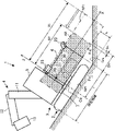
- FIG. 1 is a plan view showing a hydraulic shovel that is a construction machine according to the first to fourth embodiments of the present invention and a monitoring area set around the hydraulic shovel.
- FIG. 1B is a side view showing the hydraulic shovel and the monitoring area shown in FIG. 1A.
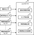
- FIG. 1 is a block diagram showing an obstacle detection device according to first to third embodiments of the present invention. It is a front view which shows the monitoring area set in the state which the said hydraulic shovel inclines large with respect to the surrounding ground in the said 1st Embodiment. It is a side view which shows the monitoring area set in the state shown by FIG. It is a top view which shows the 1st example of the surveillance area set in the said 1st Embodiment.
- FIGS. 1A-5C A first embodiment of the present invention is described below with reference to FIGS. 1A-5C.
- Drawing 1A and Drawing 1B show hydraulic excavator 1 which is an example of a construction machine concerning this embodiment.
- the hydraulic shovel 1 includes a crawler traveling body 2, a swing body 3 mounted on the traveling body 2, and a work device 4 attached to the swing body 3.
- the traveling body 2 has a traveling frame (not shown) and a pair of crawlers 2L and 2R disposed on the left and right sides thereof.
- the pair of crawlers 2L, 2R can be individually driven by a traveling hydraulic motor (not shown) provided for each of them.
- the swing body 3 is attached to the traveling body 2 via a pivoting device 7 so as to be able to pivot relative to the traveling body 2 in a yaw direction which is a direction around a pivot axis Cz in the vertical direction.
- the turning device 7 includes a turning hydraulic motor and a turning gear (not shown), and turns the turning body 3 by a driving force generated by the turning hydraulic motor.
- the revolving unit 3 is located in the front of the revolving unit 3 to allow the operator to board, and a machine room 6 located in the rear of the revolving unit 3 to accommodate an engine, hydraulic equipment, etc. And.
- the swing body 3 corresponds to an airframe of the hydraulic shovel 1 (construction machine).
- the working device 4 includes a boom 11 connected to the front so as to extend from the front of the swing body 3 and an arm 12 connected to the tip of the boom 11 so as to extend from the tip of the boom 11 And an attachment 13 attached to the tip of the arm 12.
- Each of the boom 11, the arm 12 and the attachment 13 is a pitch direction (rotation around the axis in the left-right direction of the revolving body 3) with respect to each of the revolving body 3, the boom 11 and the arm 12 by hydraulic cylinders not shown. Can be rocked in the
- the construction machine to which the present invention is applied is not limited to the hydraulic shovel 1 shown in FIG.
- the boom 11 can swing not only in the pitch direction with respect to the swing body 3 but also swing in the yaw direction with respect to the swing body 3 or move in the lateral direction of the swing body 3 It may be
- the present invention can also be applied to construction machines other than hydraulic excavators.
- the traveling body 2 is not limited to the crawler type but may be a wheel type.
- the hydraulic shovel 1 may include not only a hydraulic actuator but also an electric actuator.
- a tilt sensor 21 as shown in FIG. 2 a turning angle sensor 22, a plurality of obstacle detection sensors 23, and a controller 30 are mounted.
- the inclination sensor 21 detects an inclination angle of the revolving unit 3 with respect to the horizontal plane.
- the tilt sensor 21 according to this embodiment is constituted by a known sensor capable of detecting a tilt angle around two detection axes and generating a tilt detection signal for the tilt angle, and the swing body 3 with respect to the horizontal surface It is mounted on the revolving unit 3 so as to detect the inclination angle of More specifically, as shown in FIGS.
- the two detection axes according to the present embodiment extend in the left-right direction of the X-axis and the swing body 3 which are set to extend in the front-rear direction of the swing body 3
- the tilt sensor 21 can detect the tilt angle of the turning body 3 in the direction around the X axis and the tilt angle of the turning direction of the Y axis in the direction of the X axis. Mounted on the.
- the inclination sensor 21 can detect the inclination angle of the traveling body 2 with respect to the horizontal plane. It may be mounted on the traveling frame of the traveling body 2.
- the turning angle sensor 22 detects the turning angle of the swing body 3 with respect to the traveling body 2.
- the turning angle sensor 22 is constituted by, for example, a rotary encoder, a potentiometer, a resolver or the like, and is assembled to, for example, the turning device 7 (not shown in FIG. 1).
- Each of the obstacle detection sensors 23 is a sensor for detecting an object present around the revolving unit 3 and is constituted of, for example, a known distance measurement sensor, a stereo camera or the like.
- the plurality of obstacle detection sensors 23 detect an object (a moving object such as a person, an installation, etc.) existing around the rotating body 3 with respect to the distance and direction to the object (or the object relative to the rotating body 3). In order to be detected including the relative position), they are respectively attached to a plurality of places (for example, four places in the example shown in FIG. 1A) of the peripheral portion of the swing body 3.
- An area where the plurality of obstacle detection sensors 23 can detect an object is an area including at least a monitoring area AR set as described later around the swing body 3.
- the monitoring area AR is an area in which an obstacle detection unit 33 described later detects an object present there as an obstacle (an object having a possibility of future contact with the rotating body 3).
- the monitoring area AR is an area set around the swing body 3 and is a region relatively close to the swing body 3, and the driver of the hydraulic shovel 1 can not or can not visually recognize It is preferable that the area is difficult or overlooked.
- the monitoring area AR is an area set so as to surround the left and right sides and the rear side of the swing body 3 within a predetermined distance from the outer peripheral surface of the swing body 3. It is.
- the plurality of (four in the illustrated example) obstacle detection sensors 23 attached to the revolving unit 3 are such that at least one of the obstacle detection areas 23 can always detect an object in the monitoring area AR. Is arranged.
- the monitoring area AR exemplified in FIGS. 1A and 1B is an area equivalent to the reference area AR1, and the reference area AR1 is such that the inclination angle of the revolving unit 3 is kept substantially constant or the inclination angle
- the monitoring area is set on the premise that the hydraulic shovel 1 is operated on the ground such that the change is relatively gradual, and has a predetermined size and shape with respect to the revolving unit 3.
- the reference area AR1 has a half symmetrical shape with respect to the center line of the width of the swing body 3 in the left-right direction (Y-axis direction in FIG. 1A). While being an oblong area
- the reference area AR1 is not limited to the shape illustrated in FIGS. 1A and 1B, and various shapes may be adopted according to the outer shape and the like of the revolving unit 3.
- the controller 30 is composed of one or more electronic circuit units including a microcomputer, a memory, an interface circuit and the like, and has a function of executing various control processing and arithmetic processing.
- the controller 30 receives various sensing data including detection data generated by the tilt sensor 21, the turning angle sensor 22 and the obstacle detection sensor 23.
- the controller 30 has functions respectively corresponding to the elements constituting the obstacle detection apparatus as functions realized by the implemented hardware configuration and program (software configuration). More specifically, the controller 30 has a tilt information acquisition unit 31, an area setting unit 32, an obstacle detection unit 33, and an obstacle handling unit 34 as its functions.
- the inclination information acquisition unit 31 generates an inclination detection signal generated by the inclination sensor 21 during the operation of the hydraulic shovel 1, that is, the relative position of the swing body 3 to the ground around the hydraulic shovel 1, as described in detail later.
- the estimated value of the relative inclination angle is calculated based on the detection data of the inclination angle, and this is acquired as the inclination information.
- the inclination information setting unit 31 acquires inclination information which is information on the relative inclination state of the swing body 3 with respect to the ground around the hydraulic shovel 1.
- the ground surrounding the hydraulic shovel 1 is, more specifically, a ground present around the ground where the hydraulic shovel 1 is present, and the ground present is the ground in other words,
- the ground is present immediately below the hydraulic shovel 1.
- a ground area existing immediately below the entire swinging body 3 in other words, the entire swinging body 3
- the region where projection is made on the ground in the direction of the pivot axis Cz) and the region where the traveling body 2 comes into contact with the ground is regarded as the region where the hydraulic shovel 1 is present. It is considered as "the ground where the shovel 1 exists”.
- the hydraulic excavator has a ground close to the existing area of the hydraulic shovel 1 (for example, a ground located within a predetermined distance from the turning axis Cz or the outer peripheral surface of the revolving unit 3) It is regarded as the ground around 1.
- the existing ground (the ground on which the hydraulic shovel 1 exists) is attached with the reference sign Gr0, and the surrounding ground is attached with the reference sign Gra.
- the area setting unit 32 variably sets the monitoring area AR around the revolving unit 3. Specifically, as will be described in detail later, the inclination information acquired by the inclination information acquisition unit 31 during the operation of the hydraulic shovel 1 (the relative inclination angle of the swing body 3 with respect to the ground Gra around the hydraulic shovel 1 The monitoring area AR is set based on the estimated value of The monitoring area AR is set so as not to include the surrounding ground Gra.
- the obstacle detection unit 33 detects an object present in the monitoring area AR among objects detected by the plurality of obstacle detection sensors 23 as an obstacle. Specifically, the obstacle detection unit 33 determines the position of the object existing around the swing body 3 based on the detection data generated by the obstacle detection sensor 23 during the operation of the hydraulic shovel 1 (the swing body It is determined whether or not the relative position with respect to 3 is specified, and the specified position is a position in the monitoring area AR set by the area setting unit 32. Then, when it is determined that the position of the object is the position in the monitoring area AR, the obstacle detection unit 33 specifies the object as the obstacle, and the obstacle exists in the monitoring area AR.
- the obstacle detection processing unit 34 inputs obstacle detection information indicating.
- the obstacle detection information can include information on the position of the obstacle in the monitoring area AR.
- the obstacle handling processing unit 34 executes a predetermined handling process according to the detection. Specifically, when the obstacle detection information is given from the obstacle detection unit 33 during the operation of the hydraulic shovel 1, the obstacle handling processing unit 34 executes a handling process according to the obstacle detection information.
- the corresponding process is a restriction process for restricting at least one of the swinging operation of the swing body 3 of the hydraulic shovel 1 and the traveling operation of the traveling body 2, the driver of the hydraulic shovel 1 or the person around the hydraulic shovel 1 And / or a warning process for giving a warning to
- the restriction processing prohibits, for example, the operation of the traveling hydraulic motor to cause the traveling operation to the rear of the traveling body 2 when there is an obstacle at a position on the rear side of the traveling body 2; Or it is processing to make it stop forcibly.
- the restriction process may be a process of decelerating the traveling speed of the traveling body 2 at a decelerating degree according to the distance between the obstacle and the hydraulic excavator 1 or the like.
- the restriction process prohibits or forcibly stops the operation of the turning device 7 that causes the turning body 3 to turn when the obstacle is present at a side position of the turning body 3, for example. It is a process.
- the restriction process may be a process of decelerating the swing speed of the swing body 3 at a decelerating degree according to the distance or the positional relationship between the obstacle and the swing body 3 or the like.
- the warning process is, for example, a process of giving a warning to a driver of the hydraulic shovel 1 or a person around the hydraulic shovel 1.
- the alarm may be either a visual alarm or an audible alarm.
- the content of the alarm may be changed according to the positional relationship between the hydraulic shovel 1 and the obstacle.
- restriction processing for the traveling operation of the traveling body 2 and restriction processing for the turning operation of the revolving unit 3 A suitable process may be selectively executed from the alert process.
- the pivoting body coordinate system is a coordinate having the X axis and Y axis and the Z axis in a direction (direction of the pivot axis Cz) orthogonal to these axes as coordinate axes. It is a system.
- the operating environment ground which is the ground of the operating environment of the hydraulic shovel 1, that is, the ground constituted by the existing ground Gro and the peripheral ground Gro excluding the partial unevenness, undulations, etc.
- the tilt as described below, where it may be considered as a generally flat surface (where many portions of the operating environment ground may be considered to lie on or near a single reference plane).
- the inclination information acquisition unit 31 calculates data indicating an average (or representative) inclination angle of the operating environment ground before the operation of the hydraulic shovel 1 starts, and stores the data in a specific part of the controller 30 Perform initialization processing.
- the driver or the like is disposed in the operation room 5 or the like of the hydraulic shovel 1 in a state where the hydraulic shovel 1 is stopped at a flat portion of the operating environment ground.
- the current tilt angle of the revolving unit 3 (around each of the X and Y axes)
- Detection data indicating a detected value of the inclination angle in the direction of (1) in the aspect of the input of the inclination detection signal from the inclination sensor 21 and the detection data is an average (or representative) inclination angle of the operating environment ground
- this processing is processing for storing data in a specific part of the controller 30 as data indicating the ground reference tilt angle.
- the tilt angle acquisition unit 31 also stores and holds data about the detected value of the current swing angle of the swing body 3 together with the detection data of the ground reference tilt angle.
- the initial setting process is a process of acquiring and storing measurement data of the ground reference tilt angle measured by an arbitrary measuring device outside the hydraulic shovel 1 instead of detection data of the ground reference tilt angle by the tilt sensor 21 May be.
- the controller 30 uses data indicating the detected value of the turning angle of the turning body 3 in the initialization process. You may omit storing data in
- the operation of the hydraulic shovel 1 is performed after the execution of the initial setting process, and during the operation, the process by the inclination information acquisition unit 31 and the process by the area setting unit 32 perform predetermined calculations.
- the following steps are sequentially performed in the processing cycle.
- the inclination information acquisition unit 31 acquires a detection value of the current inclination angle of the swing body 3 indicated by the detection data included in the inclination detection signal input from the inclination sensor 21 at each operation processing cycle. At the same time, the detection value of the current turning angle of the turning body 3 is acquired. Furthermore, the inclination information acquisition unit 31 sets the difference between the detected value of the current turning angle of the turning body 3 and the value of the turning angle of the turning body 3 stored and held in the controller 30 in the initial setting process. In response, the ground reference inclination angle is converted to an inclination angle viewed in the swing body coordinate system corresponding to the current swing angle of the swing body 3.
- the inclination information acquisition unit 31 determines a relative inclination angle (a relative inclination angle in the direction around the X axis, which is a difference between the detected value of the current inclination angle of the revolving unit 3 and the ground reference inclination angle after the conversion.
- a set of relative inclination angles in the direction around the Y axis is calculated as an estimate of the current relative inclination angle of the swing body 3 with respect to the surrounding ground Gra of the hydraulic shovel 1.
- the inclination information acquisition unit 31 considers that the inclination angle of the ground around the hydraulic shovel 1 matches (or substantially matches) the ground reference inclination angle after the conversion, and inclines the revolving unit 3 with respect to the surrounding ground Gra. An estimated value of relative inclination angle as inclination information indicating a state is calculated.
- the operating environment ground can be regarded as a substantially flat surface, it is highly likely that the surrounding ground Gra is a ground having an inclination angle similar to the ground reference inclination angle. For this reason, it can be considered that the inclination angle of the surrounding ground Gra of the hydraulic shovel 1 matches (or almost matches) the ground reference inclination angle.
- the detected value of the inclination angle of the revolving unit 3 indicated by the detection data from the inclination sensor 21 may be obtained as it is as the estimated value of the relative inclination angle.
- the area setting unit 32 sets the monitoring area AR according to the relative inclination angle (estimated value) acquired by the inclination information acquisition unit 31 as described above.
- the relative inclination angle when the relative inclination angle is small (when both the magnitude of the relative inclination angle around the X axis and the magnitude of the relative inclination angle around the Y axis are small), the turning relative to the surrounding ground Gra is performed. Since the inclination of the body 3 is small, even if the monitoring area AR is set to the reference area AR1, the monitoring area AR does not include the surrounding ground Gra.
- the area setting unit 32 performs the monitoring.
- An area AR is set to the reference area AR1.
- the reference area AR1 is set as the monitoring area AR.
- the threshold is set for each of the relative inclination angle around the X axis and the relative inclination angle around the Y axis. As for these threshold values, if the relative tilt angle in the direction around the X axis and the relative tilt angle in the direction around the Y axis are below the respective threshold values, a plane corresponding to the surrounding ground Gra deviates from the reference area AR1. (The plane does not overlap with the reference area AR1), which is set in advance based on simulation or the like.
- the situation in which the magnitude of the relative inclination angle in the direction around each of the X axis and the Y axis is equal to or less than the respective threshold is a situation including the first situation in the present invention.
- the monitoring area AR is set to the reference area AR1 when the monitoring area AR is set to the reference area AR1. It may include the surrounding ground Gra. 3 and 4 illustrate such a situation.
- the situation in which the magnitude of at least one of the relative tilt angles around each of the X axis and the Y axis is larger than the threshold value corresponds to the second situation in the present invention.
- the obstacle detection unit 33 may detect the surrounding ground Gra as an obstacle.
- the area setting unit 32 determines that the monitoring area AR is the periphery
- the monitoring area AR is set so as not to include the ground Gra.
- the area setting unit 32 determines the size of the monitoring area AR in the X-axis direction according to the estimated value of the relative inclination angle ⁇ y in the direction around the Y-axis, as described below.
- the size of the monitoring area AR in the Y-axis direction is determined according to the estimated value of the relative inclination angle ⁇ x of the direction.
- the presence ground Gr0 shown in FIG. 3 is a flat slope
- the presence ground Gr0 is not limited to a flat slope.
- the revolving unit 3 can be inclined to the surrounding ground Gra in the same manner as the inclined state shown in FIG.
- the revolving unit 3 turns relative to the traveling unit 2 It may be in a state of being pivoted at any pivot angle around the axis Cz.
- the area setting unit 32 determines the size of the monitoring area AR in the X axis direction according to the relative inclination angle ⁇ y (estimated value) in the direction around the Y axis as follows. As shown in FIG. 3, in the case where the relative inclination angle ⁇ y in the direction around the Y axis is an angle in the direction in which the rear portion of the swingable body 3 approaches the surrounding ground Gra, the area setting unit 32 is the hydraulic excavator 1.
- the distance Dx is calculated using the estimated value of the relative inclination angle ⁇ y in the direction around the Y axis.
- the surrounding ground Gra when the hydraulic excavator 1 is viewed in the Y-axis direction is, as shown in FIG. It is regarded as a straight line extending from the rear end of the ground Gr0 in a direction inclined by an angle corresponding to the relative inclination angle ⁇ y with respect to the X-axis direction.
- the minimum distance Dx can be calculated by the following equation (1) .
- the height h is stored in advance in the controller 30.
- the minimum distance Dx can also be acquired using, for example, a data table or the like prepared in advance, based on the estimated value of the relative inclination angle ⁇ y in the direction around the Y axis.
- the distance R2 from the reference point P0 to the rear end of the monitoring area AR actually set is determined by the following equation (2a) or (2b) according to the magnitude relation between the distance R1 to the rear end of the reference area AR1.
- Bx in the equation (2b) is a margin constant having a predetermined positive value (bx> 0).
- the values of the distances r and R1 and the margin constant bx are stored in the controller 30 in advance.
- the reference point P0 is a point set in advance in the swing body 3 and can be set arbitrarily.
- the reference point P0 shown in FIG. 1A is set on the center line (on the X-axis in FIG. 1A) of the width of the swing body 3 in the left-right direction when the hydraulic excavator 1 is viewed from above.
- the reference point P0 may be set at a position deviated from the pivot axis Cz in the X-axis direction.
- a distance R2 from the reference point P0 to the rear end of the monitoring area AR actually set based on the above equation (2b) is the rotational body at a distance r from the reference point P0 to the rear end of the rotary body 3
- the area setting unit 32 sets the distance R2 related to the monitoring area AR to the same value as the distance R1 in the reference area AR1.
- the distance from the reference point P0 to the front end of the monitoring area AR is set to be the same as the distance R1 in the reference area AR1 in any case.
- the area setting unit 32 determines the size of the monitoring area AR in the Y-axis direction according to the relative inclination angle ⁇ x (estimated value) in the direction around the X-axis as follows.
- the relative inclination angle ⁇ x in the direction around the X axis is an angle in a direction in which one of the left and right sides of the swing body 3, for example, the right side, approaches the surrounding ground Gra.
- the area setting unit 32 starts from the right end of the revolving body 3 from the right end.
- the minimum distance (minimum distance in the Y-axis direction) Dy to Gra is calculated using the estimated value of the relative tilt angle ⁇ x in the direction around the X-axis.
- the surrounding ground Gra when the hydraulic excavator 1 is viewed in the X-axis direction is, as shown in FIG. It is regarded as a straight line extending from the right end of the ground Gr0 in a direction inclined by an angle corresponding to the relative inclination angle ⁇ x with respect to the Y-axis direction.
- the minimum distance Dy can be calculated by the following equation (3).
- the minimum distance Dy may be obtained, for example, using a data table or the like prepared in advance based on the estimated value of the relative inclination angle ⁇ x in the direction around the X axis.
- the distance Y2 from the reference point P0 to the right end of the monitoring area AR to be actually set is determined according to the following equation (4a) or (4b) according to the magnitude relation between the distance Y1 to the right end of the reference area AR1. .
- “By” in the equation (4b) is a margin constant having a predetermined positive value (by> 0).
- the values of the distances s, Y 1 and the margin constant are stored in advance in the controller 30.
- the value of the margin constant by may be the same as or different from the value of the margin constant bx in the equation (2b).
- the minimum distance Dy from the right end of the swing body 3 to the peripheral ground Gra when the hydraulic shovel 1 is viewed in the X-axis direction is from the right end of the swing body 3 to the right end of the reference area AR1.
- the situation is larger than the distance of In this case, based on the equation (4a), the distance Y2 from the reference point P0 to the right end of the monitoring area AR actually set is set to the same value as the distance Y1 in the reference area AR1.
- the minimum distance Dy from the right end of the swing body 3 to the peripheral ground Gra when the hydraulic shovel 1 is viewed in the X-axis direction is from the right end of the swing body 3 to the right end of the reference area AR1.
- the distance Y2 from the reference point P0 to the right end of the monitoring area AR actually set is the distance s from the reference point P0 to the right end of the rotating body 3 based on the equation (4b).
- the distance (the distance in the Y-axis direction) from the reference point P0 to the left end of the monitoring area AR is set to the distance (the distance Y1 in the present embodiment) in the reference area AR1.
- the area setting unit 32 detects the monitoring area from the reference point P0.
- the distance Y2 to the left end of the AR is set based on the equation (4a) or (4b) in the same manner as above, and the distance from the reference point P0 to the right end of the monitoring area AR is the distance Y1 in the reference area AR1. Set the same distance as.
- the area setting unit 32 determines the size of the monitoring area AR in the X axis direction according to the relative inclination angle ⁇ y in the Y axis direction, and sets the relative inclination angle ⁇ x in the X axis direction. In response, the size of the monitoring area AR in the Y-axis direction is determined. That is, the area setting unit 32 sets the monitoring area AR to an area having a size determined based on the relative inclination angles ⁇ y and ⁇ x.
- the area setting unit 32 sets the monitoring area AR to an area as illustrated in FIG. 5A, for example, and r + Dx> R1.
- the area setting unit 32 sets the monitoring area AR to an area having a shape illustrated in FIG. 5B, for example.
- the area setting unit 32 sets the monitoring area AR to an area as illustrated in FIG. 5C, for example.
- the monitoring area AR is set to an area corrected from the reference area AR1 so that the monitoring area AR does not include the surrounding ground Gra.
- the monitoring area AR is set to an area having a shape obtained by removing a portion near the peripheral ground Gra from the reference area AR1.
- the specific shape of the monitoring area AR is not limited.
- the rear portion of the monitoring area AR has a shape in which only a portion of the rear portion of the reference area AR1 from the reference point P0 (distance in the X-axis direction) is larger than R2 is cut away. Good. The same applies to the monitoring area AR illustrated in FIG. 5C.
- the minimum distances Dx and Dy according to the present embodiment correspond to the estimated value of the closest distance according to the present invention.
- the rear end of the swing body 3 is the swing body 3 which is an airframe.
- the right end of the revolving unit 3 ( The left end corresponds to the closest portion of the outer peripheral surface of the revolving unit 3 which is the airframe, which is the part closest to the peripheral ground Gra, and from the right end (or left end) of the revolving unit 3 in the monitoring area AR.
- the above inequality (2b) is set for a situation where the revolving unit 3 is inclined by a certain degree or more with respect to the surrounding ground Gra such that the rear part of the revolving unit 3 approaches the surrounding ground Gra.
- the inequality (4b) set for a situation where the revolving unit 3 is inclined with respect to the surrounding ground Gra such that the right or left side of the revolving unit 3 approaches the surrounding ground Gra Each corresponds to an estimation condition, that is, a condition for estimating that the monitoring area AR includes at least a part of the surrounding ground Gra.
- the monitoring area AR is set as it is in the reference area AR1 in a situation where it can be estimated that the surrounding area Gra is not included even if the monitoring area AR is set in the reference area AR1. This makes it possible to detect an obstacle around the revolving unit 3 based on a monitoring area AR having a suitable size and shape.
- the monitoring area AR includes at least a part of the surrounding ground Gra when the monitoring area AR is set to the reference area AR1 because the inclination of the swing body 3 with respect to the surrounding ground Gra is large.
- the monitoring area AR is set to an area obtained by removing a portion closer to the surrounding ground Gra from the reference area AR1 so as not to include the surrounding ground Gra. This prevents the obstacle detection unit 33 from detecting the surrounding ground Gra as an obstacle, and thereby prevents the obstacle handling processing unit 34 from executing the handling processing too frequently. .
- the monitoring area AR is set so as not to be included in the monitoring area AR including a part.
- the area setting unit 32 according to the second embodiment includes the part of the reference area AR1 which is present on the outer side (air side) of the peripheral ground Gra in the monitoring area AR as much as possible. , Set the monitoring area AR. Specifically, in the area setting unit 32 according to the second embodiment, at least one of the relative inclination angles around the X axis and the Y axis is the same as the predetermined threshold according to the first embodiment.
- the boundary of the rear of the monitoring area AR is determined according to the estimated value of the relative inclination angle ⁇ y in the direction around the Y axis, and the estimated value of the relative inclination angle ⁇ x in the direction around the X axis Then, the boundary of the side of the monitoring area AR is determined.
- the process of determining the rear boundary of the monitoring area AR is performed, for example, as follows.
- the relative inclination angle ⁇ y in the direction around the Y axis is the angle in the direction in which the rear portion of the swing body 3 approaches the surrounding ground Gra and the estimation defined by the inequality (2b)
- the area setting unit 32 sees the hydraulic shovel 1 in the Y-axis direction (when projected onto the ZX coordinate plane of the revolving body coordinate system)
- the boundary line of the rear of the monitoring area AR is set to a line offset from the line corresponding to the surrounding ground Gra by a fixed amount outside the surrounding ground Gra.
- the area setting unit 32 offsets the boundary of the rear of the monitoring area AR from the line corresponding to the surrounding ground Gra by the margin constant bx in the X-axis direction.
- the line Lc is represented by the following equation (5) in the ZX coordinate system of the rotating body coordinate system. Be done.
- R2 is a value calculated by said Formula (2b).
- z0 is a Z-axis coordinate position of the lower end surface (lower end surface in the Z-axis direction) of the swing body 3 and is stored in advance in the controller 30.
- the area setting unit 32 sets the monitoring area AR viewed in the Y-axis direction to an area in the reference area AR1 that satisfies the inequality (6).
- the relative inclination angle ⁇ y in the direction around the Y axis is the angle in the direction in which the rear portion of the rotating body 3 is brought closer to the surrounding ground Gra, and the estimation condition defined by the inequality (2b) does not hold (ie, r + Dx) If the relative inclination angle ⁇ y in the direction around the Y axis is an angle in a direction to move the rear portion of the rotating body 3 away from the surrounding ground Gra, the area setting unit 32 may As in the embodiment, the monitoring area AR viewed in the Y-axis direction is set to an area equivalent to the reference area AR1.
- the relative inclination angle ⁇ x in the direction around the X axis is an angle in the direction in which, for example, the right side of the left and right sides of the swing body 3 approaches the surrounding ground Gra.
- the area setting unit 32 sees the hydraulic shovel 1 in the X-axis direction (a pivoting body coordinate system
- the boundary line on the right side of the monitoring area AR is set to a line offset from the line corresponding to the surrounding ground Gra by a certain amount outside the surrounding ground Gra when projected onto the YZ coordinate plane of .
- the area setting unit 32 sets the boundary on the right side of the monitoring area AR by the margin constant by in the Y-axis direction from the line corresponding to the peripheral ground Gra in the example shown in FIG. Set to the offset line Ld.
- This line Ld (hereinafter sometimes referred to as the boundary line Ld) is expressed by the following equation (7) in the YZ coordinate plane of the revolving body coordinate system (the revolving body coordinate system having the reference point P0 as the origin). Ru.
- Y2 is a value calculated by the equation (4b)
- z0 is the Z of the lower end surface (lower end surface in the Z-axis direction) of the revolving unit 3 as in the equation (5) Axis coordinate position.
- the area setting unit 32 sets the monitoring area AR viewed in the X-axis direction to an area in the reference area AR1 that satisfies the inequality (8).
- the relative inclination angle ⁇ x in the direction around the X axis is an angle in the direction in which the side portion on the left side of the swing body 3 approaches the surrounding ground Gra and is defined by the inequality (4b)
- the estimation condition that is, s + Dy ⁇ Y1
- the monitoring area AR viewed in the X-axis direction is set in the same manner as described above.
- the area setting unit 32 sets the monitoring area AR viewed in the X-axis direction to be equal to the reference area AR1.
- the area setting unit 32 responds to the relative inclination angle ⁇ y in the direction around the Y axis when it is estimated that the surrounding ground Gra is included in the reference area AR1.
- Boundary line Lc of the rear portion of the monitoring area AR viewed in the Y axis direction, and the side of the monitoring area AR viewed in the X axis direction according to the relative inclination angle .theta.x in the direction around the X axis. Determine the boundary Ld.
- These boundary lines Lc and Ld are straight lines which are offset from the surrounding ground Gra by a predetermined amount and parallel to the surrounding ground Gra.
- the area setting unit 32 sets an area above the boundary lines Lc and Ld in the reference area AR1 as the monitoring area AR. For example, when r + Dx ⁇ R1 and s + Dy> Y1, the area setting unit 32 sets the monitoring area AR in the area satisfying the condition defined by inequality (6) in the reference area AR1. If r + Dx> R1 and s + Dy ⁇ Y1, the area setting unit 32 sets the monitoring area AR in an area satisfying the condition defined by inequality (8) in the reference area AR1. Further, when r + Dx ⁇ R1 and s + Dy ⁇ Y1, the area setting unit 32 sets the monitoring area AR in the area satisfying both the inequalities (6) and (8) in the reference area AR1. Set
- the margin constant bx by is set to a sufficiently small value, a portion closer to the ground ground Gra of the monitoring area AR seen in each of the Y axis direction and the X axis direction is the reference It is also possible to set the monitoring area AR so as to have a shape that substantially matches the shape obtained by removing the area overlapping the peripheral ground Gra from the area AR1 (the area that gets into the peripheral ground Gra).
- the second embodiment of the present invention is the same as the first embodiment except for the matters described above, and the same effects as the first embodiment can be obtained.
- the monitoring area AR when it is estimated that the monitoring area AR includes the surrounding ground Gra when the monitoring area AR is set to the reference area AR1, the monitoring area AR does not include the surrounding ground Gra.
- the monitoring area AR can be set so as to include as much as possible the portion of the reference area AR1 outside the surrounding ground Gra.
- a reference obstacle AR1 is set as a monitoring area AR with an actual obstacle that is not the surrounding ground Gra. It is possible to detect as well. Therefore, the omission of detection of an obstacle is effectively suppressed.
- the third embodiment is different from the first embodiment or the second embodiment only in the processing performed by the tilt information acquisition unit 31. Therefore, the following description will be mainly made on the differences, and the description of the same matters as the first embodiment or the second embodiment will be omitted.
- the inclination information acquisition unit 31 is a relative inclination angle that is inclination information indicating an inclination state relative to the surrounding ground Gra of the hydraulic shovel 1 even when the inclination angle of the operating environment ground has variations. It is configured to be able to obtain an estimate of.
- the inclination information acquisition unit 31 is configured to incline the current inclination angle of the revolving unit 3 every time the traveling unit 2 moves, for example, by a predetermined unit distance during its traveling operation.
- Detection data included in the inclination detection signal generated by the sensor 21, detection data generated by the turning angle sensor 22 for the current turning angle of the turning body 3, and detection data for the current traveling direction of the traveling body 2 And stores combinations of these detection data in time series.
- the current traveling direction of the traveling body 2 can be detected using, for example, a received signal of GNNS (Global Navigation Satellite System).
- GNNS Global Navigation Satellite System
- the tilt information acquisition unit 31 is configured to use the swing body 3 based on detection data newly acquired for a tilt angle, a turning angle, and a traveling direction, and previously acquired detection data (or detection data for a plurality of times in the past).
- the estimated value of the amount of change of the tilt angle is calculated, and this is obtained as the estimated value of the relative tilt angle.
- the change amount of the tilt angle is a change amount on the moving path immediately before the current position of the traveling body 2 and is a change amount in the swing body coordinate system corresponding to the current swing angle of the swing body 3 .
- the third embodiment is the same as the first or second embodiment except for the matters described above. According to the third embodiment, the same effect as that of the first embodiment or the second embodiment can be obtained. In addition to this, even when the inclination angle of the operating environment ground, which is the ground of the operating environment of the hydraulic excavator 1, varies, the relative inclination angle of the swing body 3 with respect to the surrounding ground Gra can be estimated with high reliability. it can. This makes it possible to set a monitoring area AR which is adapted to the actual shape of the operating environment ground.
- the fourth embodiment is different from the first embodiment or the second embodiment only in the processing performed by the inclination information acquisition unit 31. Therefore, the following description will be mainly made on the differences, and the description of the same matters as the first embodiment or the second embodiment will be omitted.
- a GNSS receiver 24 is mounted on the hydraulic shovel 1 according to the present embodiment instead of the inclination sensor 21.
- the GNSS receiver 24 receives a GNNS signal indicating the position and moving speed of the hydraulic shovel 1 and inputs the signal to the controller 30.
- the tilt information acquisition unit 31 of the controller 30 includes a terrain data storage unit 31a that stores and holds terrain data that is three-dimensional data on the terrain of the operating environment ground.
- the topography data may be downloaded to the controller 30 from a server or the like outside the hydraulic shovel 10 as needed.
- the inclination information acquisition unit 31 determines the current position of the hydraulic excavator 1 and the traveling direction of the traveling body 2 (the direction of the traveling body 2) based on the GNNS signal input from the GNSS receiver 24 at each predetermined arithmetic processing cycle. And the turning position relative to the ground Gra of the hydraulic shovel 1 at the current position based on the current position and traveling direction, the terrain data, and the detected value of the current turning angle of the turning body 3).
- a relative tilt angle of 3 (a relative tilt angle viewed in a swing body coordinate system corresponding to the current swing angle of the swing body 3) is estimated.
- the fourth embodiment is the same as the first or second embodiment except for the matters described above. Therefore, according to the fourth embodiment, the same effect as that of the first embodiment or the second embodiment can be obtained.
- the area formed by projecting the whole of the swing structure 3 on the ground in the direction of the swing axis Cz is regarded as the presence area of the hydraulic shovel 1, but is not limited thereto.
- the area formed by projecting the whole of the swing body 3 on the ground in the direction of the swing axis Cz, or the area formed by projecting the entire swing body 3 and the traveling body 2 on the ground in the direction of the swing axis Cz It may be considered as the existence area of the shovel 1.
- the size and the boundary of the monitoring area AR when the hydraulic shovel 1 is viewed in the Y-axis direction and the X-axis direction are determined for each direction, but the determination method is not limited .
- a three-dimensional plane approximating the peripheral ground Gra seen in the revolving body coordinate system is specified, and this three-dimensional plane is included in the space area (three-dimensional area) of the reference area AR1.
- the construction machine to which the present invention is applied is not limited to a hydraulic shovel.
- the present invention can be widely applied to various construction machines that require detection of an obstacle located around the fuselage.
- the airframe of the construction machine to which the present invention is applied may not turn with respect to the traveling body of the construction machine.
- the airframe may be fixed to the frame of the traveling body.
- the plurality of obstacle detection sensors 23 are mounted on the hydraulic shovel 1 (construction machine) as an object detector for detecting an object around the airframe.
- the detector may be an external sensor such as a camera installed outside the construction machine.
- controller 30 may be executed by an external computer or the like installed outside the hydraulic shovel 1 (construction machine).
- an obstacle detection device capable of detecting an obstacle present around a fuselage of a construction machine and performing a handling process corresponding to the detection result, wherein the apparatus is applied to the ground around the construction machine
- An obstacle detection device is provided that can properly detect the obstacle in consideration of a tilt state.
- an obstacle detection device configured to detect an obstacle present around a fuselage of a construction machine and execute a response process according to the detection result, and the construction on the obstacle detection device
- An inclination information acquisition unit for acquiring inclination information which is information about the relative inclination state of the vehicle with respect to the surrounding ground which is the ground existing around the existing ground where the machine exists, and monitoring around the aircraft
- An area setting unit for setting an area, an obstacle detection unit for detecting an obstacle present in the monitoring area, and a countermeasure process set in advance when the obstacle detection unit detects the obstacle
- a response processing unit is provided, and the area setting unit is configured to change the monitoring area according to the tilt information.
- the area setting unit of the obstacle detection device may set the monitoring area so as to inhibit the monitoring area from including the surrounding ground by changing the monitoring area according to the inclination information. It is possible. In other words, it is possible to change the monitoring area according to the inclination information in the direction to reduce the portion of the surrounding ground included in the monitoring area. Such a change of the monitoring area makes it possible to suppress the obstacle detection unit from detecting the surrounding ground as an obstacle and to suppress the excessive execution of the countermeasure process. In other words, the area setting unit appropriately sets the monitoring area for detecting an obstacle present around the airframe of the construction machine in consideration of the inclination with respect to the ground around the construction machine. It is possible.
- the area setting unit sets the monitoring area in a reference area set in advance in a first situation in which the body is not inclined with respect to the surrounding ground in the first situation indicated by the inclination information, and the body is the periphery In the second situation where it is indicated by the inclination information that the vehicle is inclined by a certain degree or more with respect to the ground, when the monitor area is set to the reference area, the monitor area is at least a part of the surrounding ground.
- the monitoring area is changed to an area in which a specific portion close to the surrounding ground is removed from the reference area and the surrounding ground is not included, when a predetermined estimation condition for estimating including is satisfied, It is preferable that the monitoring area is set in the reference area when the estimation condition is not satisfied.
- the area setting unit sets the monitoring area to an area obtained by removing a portion close to the surrounding ground from the reference area when the estimation condition is satisfied in the second situation, whereby the construction machine for the surrounding ground is configured.
- the surveillance area can be prevented from including the surrounding ground regardless of the inclination of the ground. This can prevent the obstacle detection unit from detecting the surrounding ground as an obstacle, and thereby appropriately prevent the response processing unit from excessively executing the response processing. Do.
- it is possible to secure a suitable area for detecting an obstacle by making the area other than the portion close to the surrounding ground in the monitoring area coincide with the reference area.
- the area setting unit is, when the estimation condition is satisfied in the second situation, the closest approach which is a distance from the closest approach portion which is a portion closest to the surrounding ground in the outer circumferential surface of the body to the surrounding ground
- the monitoring area is set so that the distance is estimated, and the distance from the closest portion to the outer peripheral boundary of the monitoring area is smaller than the estimated value of the closest distance.
- the setting of such a surveillance area makes it possible to reliably prevent that the surveillance area includes the surrounding ground.
- the closest portion may be a portion of the outer peripheral surface of the airframe which is closest to the peripheral ground in the spatial positional relationship, or when the airframe is viewed from a specific direction of the periphery of the airframe ( It may be a portion closest to the surrounding ground when viewed in a plane orthogonal to the specific direction.
- the area setting unit matches or approximates a shape obtained by removing a region overlapping the surrounding ground from the reference area from the reference area when the estimation condition is satisfied in the second situation.
- the monitoring area is configured to have a shape. This prevents the surrounding ground from being detected as an obstacle by suppressing the part of the reference area which is excluded from the monitoring area as much as possible, while preventing the surrounding obstacle of the vehicle (other than the surrounding ground Enables to secure a large monitoring area for appropriately detecting the
- the tilt information acquisition unit acquires the tilt information based on a tilt detection signal generated by a tilt sensor mounted on the construction machine so as to detect tilt angles about two different axes of the body.
- a tilt detection signal generated by a tilt sensor mounted on the construction machine so as to detect tilt angles about two different axes of the body.
- it is configured to This enables the tilt information suitable for the proper detection of the obstacle to be easily obtained using the tilt sensor.
- the tilt information acquisition unit acquires terrain data which is data on terrain of the operating environment of the construction machine and position information which is information on the position of the construction machine, and at least the terrain data and the position information The tilt information may be acquired based on This makes it possible to obtain the proper inclination information using the terrain data regardless of the position of the construction machine.
Abstract
Provided is an obstacle detection device capable of properly setting, in a manner in which the state of tilt of a construction machine with respect to the surrounding ground is considered, an area in which an obstacle present around the machine body of a construction machine is to be detected. The obstacle detection device is provided with: a tilt information obtainment unit (31) which obtains tilt information indicating the state of tilt of the machine body relative to the surrounding ground located around the ground on which the construction machine is located; and an area setting unit (32) for setting a monitoring area AR in which an obstacle is to be detected and for changing the monitoring area AR according to the tilt information.
Description
本発明は、油圧ショベル等の建設機械に設けられる障害物検出装置に関する。
The present invention relates to an obstacle detection device provided in a construction machine such as a hydraulic shovel.
従来、油圧ショベル等の建設機械に設けられる障害物検出装置として、例えば特許文献1,2に記載されるものが知られている。これらに記載される障害物検出装置は、建設機械の旋回体の周囲の所定のエリア内に障害物が存在する障害物を検出する手段と、該障害物の検出に応じて、油圧ショベルの動作(走行体の走行動作、あるいは、旋回体の旋回動作)の制限または警報の出力を行う手段と、を備える。
DESCRIPTION OF RELATED ART Conventionally, what is described, for example in patent document 1, 2 as an obstacle detection apparatus provided in construction machines, such as a hydraulic shovel, is known. The obstacle detection device described in the above includes means for detecting an obstacle in which an obstacle is present in a predetermined area around a revolving structure of a construction machine, and an operation of a hydraulic shovel according to the detection of the obstacle. And means for outputting an alarm or a restriction of (traveling operation of traveling body or pivoting operation of revolving structure).
しかし、前記建設機械が位置する地面が周辺の地面に対して大きく傾斜している場合、あるいは、地面の凹凸等に起因して建設機械が周辺の地面に対して大きく傾斜した場合、その建設機械の機体(旋回体等)の側方で該建設機械に比較的近い位置に周辺地面が存在して障害物として検出されるおそれがある。このような周辺地面の検出は、過剰な頻度での建設機械の動作の制限や警報の出力により作業効率の低下を招く。
However, if the ground on which the construction machine is located is greatly inclined to the surrounding ground, or if the construction machine is greatly inclined to the surrounding ground due to unevenness or the like of the ground, the construction machine There is a possibility that the surrounding ground exists at a position relatively close to the construction machine on the side of the airframe (swivel etc.) and is detected as an obstacle. Such detection of the surrounding ground leads to a decrease in work efficiency due to the restriction of the operation of the construction machine at an excessive frequency and the output of an alarm.
本発明は、建設機械の機体の周囲に存在する障害物を検出してその検出結果に応じて対応処理を実行することが可能な障害物検出装置であって、該建設機械の周辺の地面に対する傾斜状態を考慮した適正な検出を行うことが可能な障害物検出装置を提供することを目的とする。提供されるのは、建設機械の機体の周囲に存在する障害物を検出してその検出結果に対応した対応処理を実行するように構成された障害物検出装置であって、その上に前記建設機械が存在する地面である存在地面の周囲に存在する地面である周辺地面に対する前記機体の相対的な傾斜状態についての情報である傾斜情報を取得する傾斜情報取得部と、前記機体の周囲に監視エリアを設定するエリア設定部と、前記監視エリア内に存在する障害物を検出する障害物検出部と、当該障害物検出部が前記障害物を検出したときに予め設定された対応処理を実行する対応処理部と、を備え、前記エリア設定部は、前記傾斜情報に応じて前記監視エリアを変更するように構成されている。
The present invention is an obstacle detection device capable of detecting an obstacle existing around an airframe of a construction machine and performing a response process according to the detection result, wherein the apparatus is applied to the ground around the construction machine. An object of the present invention is to provide an obstacle detection device capable of performing appropriate detection in consideration of a tilt state. What is provided is an obstacle detection device configured to detect an obstacle present around a fuselage of a construction machine and execute a response process corresponding to the detection result, and the construction on the obstacle detection device An inclination information acquisition unit for acquiring inclination information which is information about the relative inclination state of the vehicle with respect to the surrounding ground which is the ground existing around the existing ground where the machine exists, and monitoring around the aircraft An area setting unit for setting an area, an obstacle detection unit for detecting an obstacle present in the monitoring area, and a countermeasure process set in advance when the obstacle detection unit detects the obstacle A response processing unit is provided, and the area setting unit is configured to change the monitoring area according to the tilt information.
本発明の第1実施形態を図1A~図5Cを参照して以下に説明する。図1A及び図1Bは本実施形態に係る建設機械の例である油圧ショベル1を示す。
A first embodiment of the present invention is described below with reference to FIGS. 1A-5C. Drawing 1A and Drawing 1B show hydraulic excavator 1 which is an example of a construction machine concerning this embodiment.
前記油圧ショベル1は、クローラ式の走行体2と、当該走行体2の上に搭載された旋回体3と、当該旋回体3に取り付けられた作業装置4と、を備える。
The hydraulic shovel 1 includes a crawler traveling body 2, a swing body 3 mounted on the traveling body 2, and a work device 4 attached to the swing body 3.
前記走行体2は、図略の走行フレームと、その左右両側に配置された一対のクローラ2L,2Rと、を有する。前記一対のクローラ2L,2Rは、それぞれについて装備された走行用油圧モータ(図示省略)により個別に駆動されることが可能である。
The traveling body 2 has a traveling frame (not shown) and a pair of crawlers 2L and 2R disposed on the left and right sides thereof. The pair of crawlers 2L, 2R can be individually driven by a traveling hydraulic motor (not shown) provided for each of them.
前記旋回体3は、上下方向の旋回軸Cz周りの方向であるヨー方向に走行体2に対して旋回し得るように、旋回装置7を介して該走行体2に取り付けられている。該旋回装置7は、図示を省略する旋回用油圧モータ及び旋回ギヤを含み、前記旋回用油圧モータが生成する駆動力により前記旋回体3を旋回させる。前記旋回体3は、当該旋回体3の前部に位置して作業者の搭乗を許容する運転室5と、当該旋回体3の後部に位置してエンジン、油圧機器等を収容する機械室6と、を含む。この実施形態では、前記旋回体3が前記油圧ショベル1(建設機械)の機体に相当する。
The swing body 3 is attached to the traveling body 2 via a pivoting device 7 so as to be able to pivot relative to the traveling body 2 in a yaw direction which is a direction around a pivot axis Cz in the vertical direction. The turning device 7 includes a turning hydraulic motor and a turning gear (not shown), and turns the turning body 3 by a driving force generated by the turning hydraulic motor. The revolving unit 3 is located in the front of the revolving unit 3 to allow the operator to board, and a machine room 6 located in the rear of the revolving unit 3 to accommodate an engine, hydraulic equipment, etc. And. In this embodiment, the swing body 3 corresponds to an airframe of the hydraulic shovel 1 (construction machine).
前記作業装置4は、旋回体3の前部から延びるように当該前部に連結されるブーム11と、当該ブーム11の先端部から延びるように当該ブーム11の先端部に連結されるアーム12と、当該アーム12の先端部に取付けられたアタッチメント13と、を備える。ブーム11、アーム12及びアタッチメント13のそれぞれは、図示を省略する油圧シリンダにより、旋回体3、ブーム11及びアーム12のそれぞれに対してピッチ方向(旋回体3の左右方向の軸を中心とする回転方向)に揺動可能である。
The working device 4 includes a boom 11 connected to the front so as to extend from the front of the swing body 3 and an arm 12 connected to the tip of the boom 11 so as to extend from the tip of the boom 11 And an attachment 13 attached to the tip of the arm 12. Each of the boom 11, the arm 12 and the attachment 13 is a pitch direction (rotation around the axis in the left-right direction of the revolving body 3) with respect to each of the revolving body 3, the boom 11 and the arm 12 by hydraulic cylinders not shown. Can be rocked in the
本発明が適用される建設機械は図1に示される油圧ショベル1に限られない。例えば、ブーム11は、旋回体3に対してピッチ方向に揺動し得るだけでなく、旋回体3に対してヨー方向に揺動したり、あるいは、旋回体3の左右方向に移動し得るようになっていてもよい。また、本発明は油圧ショベル以外の建設機械にも適用されることが可能である。
The construction machine to which the present invention is applied is not limited to the hydraulic shovel 1 shown in FIG. For example, the boom 11 can swing not only in the pitch direction with respect to the swing body 3 but also swing in the yaw direction with respect to the swing body 3 or move in the lateral direction of the swing body 3 It may be The present invention can also be applied to construction machines other than hydraulic excavators.
前記走行体2は、クローラ式のものに限らず、ホイール式のものであってもよい。また、油圧ショベル1は、油圧式のアクチュエータに限らず、電動式のアクチュエータを含んでいてもよい。
The traveling body 2 is not limited to the crawler type but may be a wheel type. Moreover, the hydraulic shovel 1 may include not only a hydraulic actuator but also an electric actuator.
本実施形態の油圧ショベル1には、図2に示すような傾斜センサ21と、旋回角度センサ22と、複数の障害物検知用センサ23と、コントローラ30と、が搭載されている。
In the hydraulic shovel 1 of the present embodiment, a tilt sensor 21 as shown in FIG. 2, a turning angle sensor 22, a plurality of obstacle detection sensors 23, and a controller 30 are mounted.
前記傾斜センサ21は、前記旋回体3の水平面に対する傾斜角を検出する。この実施形態に係る前記傾斜センサ21は、2つの検出軸周りの傾斜角度を検出して当該傾斜角度についての傾斜検出信号を生成することが可能な公知のセンサにより構成され、水平面に対する旋回体3の傾斜角度を検出し得るように当該旋回体3に搭載されている。より具体的に、本実施形態に係る前記2つの検出軸は、図1A及び図1Bに示す如く、旋回体3の前後方向に延びるように設定されたX軸及び旋回体3の左右方向に延びるように設定されたY軸であり、前記傾斜センサ21は、前記旋回体3の前記X軸周り方向の傾斜角度と前記Y軸周り方向の傾斜角度とをそれぞれ検出し得るように前記旋回体3に搭載されている。
The inclination sensor 21 detects an inclination angle of the revolving unit 3 with respect to the horizontal plane. The tilt sensor 21 according to this embodiment is constituted by a known sensor capable of detecting a tilt angle around two detection axes and generating a tilt detection signal for the tilt angle, and the swing body 3 with respect to the horizontal surface It is mounted on the revolving unit 3 so as to detect the inclination angle of More specifically, as shown in FIGS. 1A and 1B, the two detection axes according to the present embodiment extend in the left-right direction of the X-axis and the swing body 3 which are set to extend in the front-rear direction of the swing body 3 And the tilt sensor 21 can detect the tilt angle of the turning body 3 in the direction around the X axis and the tilt angle of the turning direction of the Y axis in the direction of the X axis. Mounted on the.
この実施の形態に係る前記旋回体3の傾斜角度は前記走行体2の傾斜角度に一致もしくはほぼ一致するので、前記傾斜センサ21は、水平面に対する前記走行体2の傾斜角度を検出し得るように当該走行体2の前記走行フレームに搭載されていてもよい。
Since the inclination angle of the swing body 3 according to this embodiment matches or substantially matches the inclination angle of the traveling body 2, the inclination sensor 21 can detect the inclination angle of the traveling body 2 with respect to the horizontal plane. It may be mounted on the traveling frame of the traveling body 2.
前記旋回角度センサ22は、走行体2に対する旋回体3の旋回角度を検出するものである。当該旋回角度センサ22は、例えばロータリエンコーダ、ポテンショメータ、レゾルバ等により構成され、例えば前記旋回装置7に組み付けられている(図1では図省略)。
The turning angle sensor 22 detects the turning angle of the swing body 3 with respect to the traveling body 2. The turning angle sensor 22 is constituted by, for example, a rotary encoder, a potentiometer, a resolver or the like, and is assembled to, for example, the turning device 7 (not shown in FIG. 1).
前記障害物検知用センサ23のそれぞれは、前記旋回体3の周囲に存在する物体を検知するためのセンサであり、例えば公知の測距センサ、ステレオカメラ等により構成される。当該複数の障害物検知用センサ23は、旋回体3の周囲に存在する物体(人等の移動物体、設置物等)を、該物体までの距離及び方位(あるいは、旋回体3に対する該物体の相対位置)を含めて検知し得るように、旋回体3の周縁部の複数個所(図1Aに示す例では、例えば4か所)にそれぞれ取り付けられている。
Each of the obstacle detection sensors 23 is a sensor for detecting an object present around the revolving unit 3 and is constituted of, for example, a known distance measurement sensor, a stereo camera or the like. The plurality of obstacle detection sensors 23 detect an object (a moving object such as a person, an installation, etc.) existing around the rotating body 3 with respect to the distance and direction to the object (or the object relative to the rotating body 3). In order to be detected including the relative position), they are respectively attached to a plurality of places (for example, four places in the example shown in FIG. 1A) of the peripheral portion of the swing body 3.
前記複数の障害物検知用センサ23が物体を検知することが可能な領域は、旋回体3の周囲において後述する如く設定される監視エリアARを少なくとも包含する領域である。該監視エリアARは、そこに存在する物体を、後述する障害物検出部33が障害物(旋回体3との将来の接触の虞がある物体)として検出する領域である。
An area where the plurality of obstacle detection sensors 23 can detect an object is an area including at least a monitoring area AR set as described later around the swing body 3. The monitoring area AR is an area in which an obstacle detection unit 33 described later detects an object present there as an obstacle (an object having a possibility of future contact with the rotating body 3).
該監視エリアARは、本実施形態では、旋回体3の周囲に設定される領域であって、旋回体3に比較的近い領域であると共に、油圧ショベル1の運転者が視認できない、もしくは視認し難い、もしくは、見落としやすい領域であることが、好ましい。当該監視エリアARは、例えば、図1Aおよび図1Bに例示する如く、旋回体3の外周面から所定の距離内で、該旋回体3の左右の両側及び後側を囲むように設定された領域である。前記旋回体3に取り付けられた前記複数の(図示例では4つの)障害物検知用センサ23は、そのうちの少なくとも一つの障害物検知エリア23が必ず監視エリアAR内の物体を検知し得るように、配置されている。
In the present embodiment, the monitoring area AR is an area set around the swing body 3 and is a region relatively close to the swing body 3, and the driver of the hydraulic shovel 1 can not or can not visually recognize It is preferable that the area is difficult or overlooked. For example, as illustrated in FIG. 1A and FIG. 1B, the monitoring area AR is an area set so as to surround the left and right sides and the rear side of the swing body 3 within a predetermined distance from the outer peripheral surface of the swing body 3. It is. The plurality of (four in the illustrated example) obstacle detection sensors 23 attached to the revolving unit 3 are such that at least one of the obstacle detection areas 23 can always detect an object in the monitoring area AR. Is arranged.
図1A及び図1Bに例示される監視エリアARは基準エリアAR1と同等のエリアであり、当該基準エリアAR1は、前記旋回体3の傾斜角度がほぼ一定に保たれるか、もしくは該傾斜角度の変化が比較的緩やかなものとなるような地面上で油圧ショベル1の動作を行うという前提で設定された監視エリアであり、旋回体3に対してあらかじめ定められたサイズ及び形状を有する。
The monitoring area AR exemplified in FIGS. 1A and 1B is an area equivalent to the reference area AR1, and the reference area AR1 is such that the inclination angle of the revolving unit 3 is kept substantially constant or the inclination angle The monitoring area is set on the premise that the hydraulic shovel 1 is operated on the ground such that the change is relatively gradual, and has a predetermined size and shape with respect to the revolving unit 3.
前記基準エリアAR1は、例えば図1Aに例示する如く、油圧ショベル1の上方から見て、旋回体3の左右方向(図1AのY軸方向)の幅の中心線に対して左右対称形状の半長円状の領域であると共に、図1Bに例示する如く、油圧ショベル1の高さ方向(旋回軸Czの方向)に一定の厚さを有する領域である。
For example, as illustrated in FIG. 1A, the reference area AR1 has a half symmetrical shape with respect to the center line of the width of the swing body 3 in the left-right direction (Y-axis direction in FIG. 1A). While being an oblong area | region, it is an area | region which has fixed thickness in the height direction (direction of the turning axis Cz) of the hydraulic shovel 1, as illustrated to FIG. 1B.
油圧ショベル1の動作環境における地面の凹凸やうねり、斜面の傾き変化等により、旋回体3の傾斜角度の変化が生じやすい地面上で油圧ショベル1の動作が行われる状況では、監視エリアARのサイズや形状は、後述するように、基準エリアAR1から適宜変更されることが好ましい。一方、前記基準エリアAR1は、図1A及び図1Bに例示した形状のものに限らず、旋回体3の外形状等に応じて、種々様々な形状を採用し得る。
The size of the monitoring area AR in a situation where the hydraulic shovel 1 is operated on the ground where the change of the inclination angle of the swingable body 3 is likely to occur due to unevenness and waviness of the ground in the operating environment of the hydraulic shovel 1 and inclination change of slopes. It is preferable that the shape is appropriately changed from the reference area AR1 as described later. On the other hand, the reference area AR1 is not limited to the shape illustrated in FIGS. 1A and 1B, and various shapes may be adopted according to the outer shape and the like of the revolving unit 3.
コントローラ30は、マイコン、メモリ、インターフェース回路等を含む一つ以上の電子回路ユニットにより構成され、種々の制御処理及び演算処理を実行する機能を有する。このコントローラ30には、前記傾斜センサ21、旋回角度センサ22及び障害物検知用センサ23のそれぞれにより生成される検出データを含む種々のセンシングデータが入力される。
The controller 30 is composed of one or more electronic circuit units including a microcomputer, a memory, an interface circuit and the like, and has a function of executing various control processing and arithmetic processing. The controller 30 receives various sensing data including detection data generated by the tilt sensor 21, the turning angle sensor 22 and the obstacle detection sensor 23.
前記コントローラ30は、実装されたハードウェア構成及びプログラム(ソフトウェア構成)により実現される機能として、障害物検出装置を構成する要素にそれぞれ対応する機能を有する。より具体的には、コントローラ30は、その機能として、傾斜情報取得部31と、エリア設定部32と、障害物検出部33と、障害物対応処理部34とを有する。
The controller 30 has functions respectively corresponding to the elements constituting the obstacle detection apparatus as functions realized by the implemented hardware configuration and program (software configuration). More specifically, the controller 30 has a tilt information acquisition unit 31, an area setting unit 32, an obstacle detection unit 33, and an obstacle handling unit 34 as its functions.
前記傾斜情報取得部31は、後に詳述するように、油圧ショベル1の動作中に前記傾斜センサ21が生成する傾斜検出信号、すなわち、該油圧ショベル1の周辺地面に対する旋回体3の相対的な傾斜角度についての検出データ、に基づいて推定し、その相対的な傾斜角度の推定値を演算し、これを上記傾斜情報として取得する。このようにして、当該傾斜情報設定部31は、前記油圧ショベル1の周辺地面に対する旋回体3の相対的な傾斜状態についての情報である傾斜情報を取得する。
The inclination information acquisition unit 31 generates an inclination detection signal generated by the inclination sensor 21 during the operation of the hydraulic shovel 1, that is, the relative position of the swing body 3 to the ground around the hydraulic shovel 1, as described in detail later. The estimated value of the relative inclination angle is calculated based on the detection data of the inclination angle, and this is acquired as the inclination information. Thus, the inclination information setting unit 31 acquires inclination information which is information on the relative inclination state of the swing body 3 with respect to the ground around the hydraulic shovel 1.
ここで、前記油圧ショベル1の周辺地面というのは、より詳しくは、その上に当該油圧ショベル1が存在する地面である存在地面の周囲に存在する地面であり、前記存在地面は、換言すれば、前記油圧ショベル1を旋回軸Czの方向で上方から見た場合に、該油圧ショベル1の直下に存在する地面である。具体的に、本実施形態では、油圧ショベル1を旋回軸Czの方向で上方から見た場合に、例えば、旋回体3の全体の直下に存在する地面領域(換言すれば、旋回体3の全体を旋回軸Czの方向で地面に投影してなる領域)及び走行体2が接地する領域が油圧ショベル1の存在領域とみなされ、該存在領域内の地面が前記存在地面すなわち「その上に油圧ショベル1が存在する地面」とみなされる。
Here, the ground surrounding the hydraulic shovel 1 is, more specifically, a ground present around the ground where the hydraulic shovel 1 is present, and the ground present is the ground in other words, When the hydraulic shovel 1 is viewed from above in the direction of the turning axis Cz, the ground is present immediately below the hydraulic shovel 1. Specifically, in the present embodiment, when the hydraulic shovel 1 is viewed from above in the direction of the turning axis Cz, for example, a ground area existing immediately below the entire swinging body 3 (in other words, the entire swinging body 3) The region where projection is made on the ground in the direction of the pivot axis Cz) and the region where the traveling body 2 comes into contact with the ground is regarded as the region where the hydraulic shovel 1 is present. It is considered as "the ground where the shovel 1 exists".
一方、前記存在地面の外側にある地面のうち、前記油圧ショベル1の前記存在領域に近い地面(例えば、旋回軸Czもしくは旋回体3の外周面から所定の距離内にある地面)が前記油圧ショベル1の周辺地面とみなされる。
On the other hand, among the grounds located outside the existing ground, the hydraulic excavator has a ground close to the existing area of the hydraulic shovel 1 (for example, a ground located within a predetermined distance from the turning axis Cz or the outer peripheral surface of the revolving unit 3) It is regarded as the ground around 1.
以降の説明では、図1Bに例示する如く、前記存在地面(その上に油圧ショベル1が存在する地面)に参照符号Gr0が付され、周辺地面に参照符号Graが付される。
In the following description, as illustrated in FIG. 1B, the existing ground (the ground on which the hydraulic shovel 1 exists) is attached with the reference sign Gr0, and the surrounding ground is attached with the reference sign Gra.
前記エリア設定部32は、旋回体3の周囲に監視エリアARを可変的に設定する。具体的には、後に詳述するように、前記油圧ショベル1の動作中に前記傾斜情報取得部31によって取得された傾斜情報(油圧ショベル1の周辺地面Graに対する旋回体3の相対的な傾斜角度の推定値)に基づいて、前記監視エリアARを設定する。この監視エリアARは、前記周辺地面Graを含まないように設定される。
The area setting unit 32 variably sets the monitoring area AR around the revolving unit 3. Specifically, as will be described in detail later, the inclination information acquired by the inclination information acquisition unit 31 during the operation of the hydraulic shovel 1 (the relative inclination angle of the swing body 3 with respect to the ground Gra around the hydraulic shovel 1 The monitoring area AR is set based on the estimated value of The monitoring area AR is set so as not to include the surrounding ground Gra.
前記障害物検出部33は、前記複数の障害物検知センサ23により検知される物体のうち前記監視エリアAR内に存在する物体を障害物として検出するものである。具体的に、当該障害物検出部33は、前記油圧ショベル1の動作中に前記障害物検知用センサ23によって生成された検出データに基づき、旋回体3の周囲に存在する物体の位置(旋回体3に対する相対位置)を特定し、その特定した位置が、エリア設定部32で設定された監視エリアAR内の位置であるか否かを判断する。そして、当該障害物検出部33は、前記物体の位置が監視エリアAR内の位置であると判断した場合に当該物体を前記障害物として特定し、前記監視エリアAR内に障害物が存在することを示す障害物検知情報を障害物対応処理部34に入力する。この障害物検知情報は、前記監視エリアAR内の障害物の位置に関する情報を含むことが可能である。
The obstacle detection unit 33 detects an object present in the monitoring area AR among objects detected by the plurality of obstacle detection sensors 23 as an obstacle. Specifically, the obstacle detection unit 33 determines the position of the object existing around the swing body 3 based on the detection data generated by the obstacle detection sensor 23 during the operation of the hydraulic shovel 1 (the swing body It is determined whether or not the relative position with respect to 3 is specified, and the specified position is a position in the monitoring area AR set by the area setting unit 32. Then, when it is determined that the position of the object is the position in the monitoring area AR, the obstacle detection unit 33 specifies the object as the obstacle, and the obstacle exists in the monitoring area AR. The obstacle detection processing unit 34 inputs obstacle detection information indicating. The obstacle detection information can include information on the position of the obstacle in the monitoring area AR.
前記障害物対応処理部34は、前記監視エリアAR内で障害物が検出された場合に、その検出に応じて所定の対応処理を実行する。具体的に、当該障害物対応処理部34は、前記油圧ショベル1の動作中に前記障害物検出部33から前記障害物検知情報が与えられた場合に、それに応じた対応処理を実行する。当該対応処理は、前記油圧ショベル1の旋回体3の旋回動作及び前記走行体2の走行動作の少なくとも一方の動作を制限する制限処理、前記油圧ショベル1の運転者もしくは油圧ショベル1の周囲の者に対して警報を与える警告処理、のうちの少なくとも一方を含む。
When an obstacle is detected in the monitoring area AR, the obstacle handling processing unit 34 executes a predetermined handling process according to the detection. Specifically, when the obstacle detection information is given from the obstacle detection unit 33 during the operation of the hydraulic shovel 1, the obstacle handling processing unit 34 executes a handling process according to the obstacle detection information. The corresponding process is a restriction process for restricting at least one of the swinging operation of the swing body 3 of the hydraulic shovel 1 and the traveling operation of the traveling body 2, the driver of the hydraulic shovel 1 or the person around the hydraulic shovel 1 And / or a warning process for giving a warning to
前記制限処理は、例えば、走行体2の後方側の位置に障害物が存在する場合に当該走行体2の後方への走行動作を行わせるような前記走行用油圧モータの作動)を禁止し、もしくは強制的に停止させる処理である。当該制限処理は、あるいは、前記障害物と前記油圧ショベル1との距離等に応じた減速度合いで走行体2の走行速度を減速させる処理であってもよい。
The restriction processing prohibits, for example, the operation of the traveling hydraulic motor to cause the traveling operation to the rear of the traveling body 2 when there is an obstacle at a position on the rear side of the traveling body 2; Or it is processing to make it stop forcibly. Alternatively, the restriction process may be a process of decelerating the traveling speed of the traveling body 2 at a decelerating degree according to the distance between the obstacle and the hydraulic excavator 1 or the like.
前記制限処理は、例えば、前記旋回体3の側方の位置に障害物が存在する場合に当該旋回体3の旋回動作を行わせる前記旋回装置7の作動を禁止し、もしくは強制的に停止させる処理である。当該制限処理は、あるいは、前記障害物と前記旋回体3との距離もしくは位置関係等に応じた減速度合いで前記旋回体3の旋回速度を減速させる処理であってもよい。
The restriction process prohibits or forcibly stops the operation of the turning device 7 that causes the turning body 3 to turn when the obstacle is present at a side position of the turning body 3, for example. It is a process. Alternatively, the restriction process may be a process of decelerating the swing speed of the swing body 3 at a decelerating degree according to the distance or the positional relationship between the obstacle and the swing body 3 or the like.
前記警告処理は、例えば、前記油圧ショベル1の運転者もしくは油圧ショベル1の周囲の者に対して警報を与える処理である。該警報は、視覚的な警報及び聴覚的な警報のいずれであってもよい。
The warning process is, for example, a process of giving a warning to a driver of the hydraulic shovel 1 or a person around the hydraulic shovel 1. The alarm may be either a visual alarm or an audible alarm.
前記警報の内容は前記油圧ショベル1と前記障害物との位置関係等に応じて変更されてもよい。また、油圧ショベル1と障害物との位置関係、油圧ショベル1の動作状況等に応じて、前記走行体2の走行動作についての制限処理と、旋回体3の旋回動作についての制限処理と、前記警告処理との中から好適な処理が選択的に実行されてもよい。
The content of the alarm may be changed according to the positional relationship between the hydraulic shovel 1 and the obstacle. In addition, according to the positional relationship between the hydraulic shovel 1 and the obstacle, the operation condition of the hydraulic shovel 1, etc., restriction processing for the traveling operation of the traveling body 2 and restriction processing for the turning operation of the revolving unit 3 A suitable process may be selectively executed from the alert process.
次に、前記傾斜情報取得部31により行われる処理と、前記エリア設定部32により行われる処理をさらに詳細に説明する。以降の説明は旋回体座標系という用語を含み、当該旋回体座標系は、前記X軸及びY軸と、これらに直交する方向(前記旋回軸Czの方向)のZ軸とを座標軸とする座標系である。
Next, the process performed by the inclination information acquisition unit 31 and the process performed by the area setting unit 32 will be described in more detail. The following description includes the term "swing body coordinate system", and the pivoting body coordinate system is a coordinate having the X axis and Y axis and the Z axis in a direction (direction of the pivot axis Cz) orthogonal to these axes as coordinate axes. It is a system.
本実施形態では、例えば、前記油圧ショベル1の動作環境の地面である動作環境地面、すなわち、前記存在地面Gro及び前記周辺地面Groにより構成される地面が、部分的な凹凸やうねり等を除いて、概ね平坦な面とみなし得る場合(前記動作環境地面の多くの部分が単一の基準平面上、又は該基準平面に近い位置に存在するとみなし得る場合)において、以下に説明する如く、前記傾斜情報取得部31の処理と、前記エリア設定部32の処理とが実行される。
In the present embodiment, for example, the operating environment ground, which is the ground of the operating environment of the hydraulic shovel 1, that is, the ground constituted by the existing ground Gro and the peripheral ground Gro excluding the partial unevenness, undulations, etc. The tilt, as described below, where it may be considered as a generally flat surface (where many portions of the operating environment ground may be considered to lie on or near a single reference plane). The processing of the information acquisition unit 31 and the processing of the area setting unit 32 are executed.
前記傾斜情報取得部31は、前記油圧ショベル1の動作開始前に、前記動作環境地面の平均的(もしくは代表的)な傾斜角度を示すデータを算定して前記コントローラ30の特定部位に記憶保持させる初期設定処理を行う。
The inclination information acquisition unit 31 calculates data indicating an average (or representative) inclination angle of the operating environment ground before the operation of the hydraulic shovel 1 starts, and stores the data in a specific part of the controller 30 Perform initialization processing.
この初期設定処理は、より具体的には、油圧ショベル1が前記動作環境地面のうちの平坦な部分に停車した状態で、運転者等が当該油圧ショベル1の運転室5等に配置された操作部(図示省略)に所定の操作を与えることに応じて、あるいは、外部のサーバ等から与えられる指令に応じて、前記旋回体3の現在の傾斜角度(前記X軸及びY軸の各軸周りの方向の傾斜角度)の検出値を示す検出データを傾斜センサ21からの傾斜検出信号の入力という態様で取得し、当該検出データを前記動作環境地面の平均的(もしくは代表的)な傾斜角度(以降、地面基準傾斜角度という)を示すデータとしてコントローラ30の特定部位に記憶保持させる処理である。この初期設定処理では、前記傾斜角度取得部31は、前記旋回体3の現在の旋回角度の検出値についてのデータも前記地面基準傾斜角度の検出データと共に記憶保持される。
More specifically, in this initial setting process, the driver or the like is disposed in the operation room 5 or the like of the hydraulic shovel 1 in a state where the hydraulic shovel 1 is stopped at a flat portion of the operating environment ground. In accordance with giving a predetermined operation to the unit (not shown), or according to a command given from an external server or the like, the current tilt angle of the revolving unit 3 (around each of the X and Y axes) Detection data indicating a detected value of the inclination angle in the direction of (1) in the aspect of the input of the inclination detection signal from the inclination sensor 21 and the detection data is an average (or representative) inclination angle of the operating environment ground ( Hereinafter, this processing is processing for storing data in a specific part of the controller 30 as data indicating the ground reference tilt angle. In this initial setting process, the tilt angle acquisition unit 31 also stores and holds data about the detected value of the current swing angle of the swing body 3 together with the detection data of the ground reference tilt angle.
前記初期設定処理は、前記傾斜センサ21による地面基準傾斜角度の検出データの代わりに油圧ショベル1の外部の任意の測定器で測定された地面基準傾斜角度の測定データを取得して記憶保持する処理でもよい。また、地面基準傾斜角度がゼロもしくはほぼゼロである場合(動作環境の地面が概ね水平面とみなし得る場合)には、初期設定処理において、旋回体3の旋回角度の検出値を示すデータをコントローラ30に記憶保持することを省略してもよい。
The initial setting process is a process of acquiring and storing measurement data of the ground reference tilt angle measured by an arbitrary measuring device outside the hydraulic shovel 1 instead of detection data of the ground reference tilt angle by the tilt sensor 21 May be. In addition, when the ground reference inclination angle is zero or almost zero (when the ground of the operating environment can be regarded as a generally horizontal plane), the controller 30 uses data indicating the detected value of the turning angle of the turning body 3 in the initialization process. You may omit storing data in
本実施形態では、かかる初期設定処理の実行後に、油圧ショベル1の動作が行われ、その動作中に、前記傾斜情報取得部31による処理と、前記エリア設定部32による処理とが、所定の演算処理周期で逐次、次のように実行される。
In the present embodiment, the operation of the hydraulic shovel 1 is performed after the execution of the initial setting process, and during the operation, the process by the inclination information acquisition unit 31 and the process by the area setting unit 32 perform predetermined calculations. The following steps are sequentially performed in the processing cycle.
前記傾斜情報取得部31は、各演算処理周期で、前記傾斜センサ21から入力される前記傾斜検出信号に含まれる前記検出データにより示される前記旋回体3の現在の傾斜角度の検出値を取得すると共に、前記旋回体3の現在の旋回角度の検出値を取得する。さらに、前記傾斜情報取得部31は、前記旋回体3の現在の旋回角度の検出値と、前記初期設定処理で前記コントローラ30に記憶保持された前記旋回体3の旋回角度の値との差に応じて、前記地面基準傾斜角度を、前記旋回体3の現在の旋回角度に対応する旋回体座標系で見た傾斜角度に変換する。
The inclination information acquisition unit 31 acquires a detection value of the current inclination angle of the swing body 3 indicated by the detection data included in the inclination detection signal input from the inclination sensor 21 at each operation processing cycle. At the same time, the detection value of the current turning angle of the turning body 3 is acquired. Furthermore, the inclination information acquisition unit 31 sets the difference between the detected value of the current turning angle of the turning body 3 and the value of the turning angle of the turning body 3 stored and held in the controller 30 in the initial setting process. In response, the ground reference inclination angle is converted to an inclination angle viewed in the swing body coordinate system corresponding to the current swing angle of the swing body 3.
そして、前記傾斜情報取得部31は、前記旋回体3の現在の傾斜角度の検出値と、上記変換後の地面基準傾斜角度との差である相対傾斜角度(X軸周り方向の相対傾斜角度及びY軸周り方向の相対傾斜角度の組)を、前記油圧ショベル1の周辺地面Graに対する前記旋回体3の現在の相対的な傾斜角度の推定値として算出する。
Then, the inclination information acquisition unit 31 determines a relative inclination angle (a relative inclination angle in the direction around the X axis, which is a difference between the detected value of the current inclination angle of the revolving unit 3 and the ground reference inclination angle after the conversion. A set of relative inclination angles in the direction around the Y axis) is calculated as an estimate of the current relative inclination angle of the swing body 3 with respect to the surrounding ground Gra of the hydraulic shovel 1.
すなわち、前記傾斜情報取得部31は、前記油圧ショベル1の周辺地面の傾斜角度が上記変換後の地面基準傾斜角度に一致(もしくはほぼ一致)するとみなして、前記周辺地面Graに対する旋回体3の傾斜状態を示す傾斜情報としての相対傾斜角度の推定値を算出する。
That is, the inclination information acquisition unit 31 considers that the inclination angle of the ground around the hydraulic shovel 1 matches (or substantially matches) the ground reference inclination angle after the conversion, and inclines the revolving unit 3 with respect to the surrounding ground Gra. An estimated value of relative inclination angle as inclination information indicating a state is calculated.
ここで、本実施形態では、前記動作環境地面が概ね平坦な面とみなし得るので、前記周辺地面Graは、概ね、地面基準傾斜角度と同程度の傾斜角度をもつ地面である可能性が高い。このため、油圧ショベル1の周辺地面Graの傾斜角度が地面基準傾斜角度に一致(もしくはほぼ一致)するとみなし得る。
Here, in the present embodiment, since the operating environment ground can be regarded as a substantially flat surface, it is highly likely that the surrounding ground Gra is a ground having an inclination angle similar to the ground reference inclination angle. For this reason, it can be considered that the inclination angle of the surrounding ground Gra of the hydraulic shovel 1 matches (or almost matches) the ground reference inclination angle.
前記地面基準傾斜角度がゼロもしくはほぼゼロである場合、前記傾斜センサ21からの検出データにより示される前記旋回体3の傾斜角度の検出値がそのまま相対傾斜角度の推定値として取得されてもよい。
When the ground reference inclination angle is zero or almost zero, the detected value of the inclination angle of the revolving unit 3 indicated by the detection data from the inclination sensor 21 may be obtained as it is as the estimated value of the relative inclination angle.
前記エリア設定部32は、本実施形態では、上記の如く傾斜情報取得部31により取得された相対傾斜角度(推定値)に応じて、監視エリアARを設定する。
In the present embodiment, the area setting unit 32 sets the monitoring area AR according to the relative inclination angle (estimated value) acquired by the inclination information acquisition unit 31 as described above.
ここで、上記相対傾斜角度が小さい場合(X軸周り方向の相対傾斜角度の大きさ及びY軸周り方向の相対傾斜角度の大きさの双方が小さい場合)には、前記周辺地面Graに対する前記旋回体3の傾きが小さいので、前記監視エリアARを前記基準エリアAR1に設定しても、該監視エリアARは前記周辺地面Graを含まない。
Here, when the relative inclination angle is small (when both the magnitude of the relative inclination angle around the X axis and the magnitude of the relative inclination angle around the Y axis are small), the turning relative to the surrounding ground Gra is performed. Since the inclination of the body 3 is small, even if the monitoring area AR is set to the reference area AR1, the monitoring area AR does not include the surrounding ground Gra.
そこで、前記エリア設定部32は、X軸及びY軸の各軸周りの方向の相対傾斜角度のそれぞれの大きさ(絶対値)があらかじめ定められた所定の閾値以下である場合には、前記監視エリアARを前記基準エリアAR1に設定する。例えば、図1A及び図1Bに示す如く、油圧ショベル1の存在領域の地面である前記存在地面Gr0と前記周辺地面Graとが面一(もしくはほぼ面一)の平坦面であるような場合には、監視エリアARとして前記基準エリアAR1が設定される。
Therefore, when the size (absolute value) of the relative inclination angle in the direction around each of the X axis and the Y axis is equal to or less than a predetermined threshold, the area setting unit 32 performs the monitoring. An area AR is set to the reference area AR1. For example, as shown in FIGS. 1A and 1B, in the case where the existing ground Gr0, which is the ground of the region where the hydraulic shovel 1 is present, and the peripheral ground Gra are flat (or almost flush) flat surfaces. The reference area AR1 is set as the monitoring area AR.
前記閾値は、X軸周り方向の相対傾斜角度及びY軸周り方向の相対傾斜角度のそれぞれについて設定される。これらの閾値は、X軸周り方向の相対傾斜角度及びY軸周り方向の相対傾斜角度がそれぞれの前記閾値以下であれば前記周辺地面Graに相当する平面が前記基準エリアAR1から逸脱した状態となる(該平面が基準エリアAR1と重ならない)ように、シミュレーション等に基づいてあらかじめ設定される。
The threshold is set for each of the relative inclination angle around the X axis and the relative inclination angle around the Y axis. As for these threshold values, if the relative tilt angle in the direction around the X axis and the relative tilt angle in the direction around the Y axis are below the respective threshold values, a plane corresponding to the surrounding ground Gra deviates from the reference area AR1. (The plane does not overlap with the reference area AR1), which is set in advance based on simulation or the like.
前記X軸及びY軸の各軸周りの方向の相対傾斜角度のそれぞれの大きさがそれぞれの閾値以下である状況は、本発明における第1状況を含む状況である。
The situation in which the magnitude of the relative inclination angle in the direction around each of the X axis and the Y axis is equal to or less than the respective threshold is a situation including the first situation in the present invention.
逆に、X軸及びY軸の各軸周りの相対傾斜角度の少なくとも一方の大きさがその閾値よりも大きい場合、前記監視エリアARが前記基準エリアAR1に設定されると該監視エリアARが前記周辺地面Graを含む可能性がある。図3及び図4は、このような状況を例示している。このようにX軸及びY軸の各軸周りの相対傾斜角度の少なくとも一方の大きさがその閾値よりも大きい状況は、本発明における第2状況に相当する。
Conversely, if the size of at least one of the relative inclination angles around each of the X axis and the Y axis is larger than the threshold value, the monitoring area AR is set to the reference area AR1 when the monitoring area AR is set to the reference area AR1. It may include the surrounding ground Gra. 3 and 4 illustrate such a situation. The situation in which the magnitude of at least one of the relative tilt angles around each of the X axis and the Y axis is larger than the threshold value corresponds to the second situation in the present invention.
このような第2状況において前記監視エリアARが前記基準エリアAR1に設定されると、前記障害物検出部33が前記周辺地面Graを障害物として検出する虞がある。
If the monitoring area AR is set to the reference area AR1 in such a second situation, the obstacle detection unit 33 may detect the surrounding ground Gra as an obstacle.
そこで、本実施形態に係るエリア設定部32は、前記X軸及びY軸の各軸周りの相対傾斜角度の少なくとも一方の大きさがその閾値よりも大きい場合には、前記監視エリアARが前記周辺地面Graを含まないように該監視エリアARを設定する。具体的に、前記エリア設定部32は、以下に説明する如く、前記Y軸周り方向の相対傾斜角度θyの推定値に応じてX軸方向における監視エリアARのサイズを決定し、前記X軸周り方向の相対傾斜角度θxの推定値に応じてY軸方向における監視エリアARのサイズを決定する。
Therefore, when the size of at least one of the relative inclination angles around each of the X axis and the Y axis is larger than the threshold value, the area setting unit 32 according to the present embodiment determines that the monitoring area AR is the periphery The monitoring area AR is set so as not to include the ground Gra. Specifically, the area setting unit 32 determines the size of the monitoring area AR in the X-axis direction according to the estimated value of the relative inclination angle θy in the direction around the Y-axis, as described below. The size of the monitoring area AR in the Y-axis direction is determined according to the estimated value of the relative inclination angle θx of the direction.
図3に示される前記存在地面Gr0は平坦な斜面であるが、当該存在地面Gr0は平坦な斜面に限られない。例えば走行体2の前部が地面の凸部に乗り上げることによっても前記旋回体3は前記周辺地面Graに対して図3に示される傾斜状態と同様に傾くことが可能である。
Although the presence ground Gr0 shown in FIG. 3 is a flat slope, the presence ground Gr0 is not limited to a flat slope. For example, even when the front part of the traveling body 2 rides on the convex portion of the ground, the revolving unit 3 can be inclined to the surrounding ground Gra in the same manner as the inclined state shown in FIG.
また、図3では、走行体2の前後方向と旋回体3の前後方向(X軸方向)とが互いに同じ方向として示されているが、前記旋回体3は前記走行体2に対して前記旋回軸Czの周りに任意の旋回角度で旋回した状態であってもよい。
Moreover, in FIG. 3, although the front-back direction of the traveling body 2 and the front-back direction (X-axis direction) of the revolving unit 3 are shown as the same direction, the revolving unit 3 turns relative to the traveling unit 2 It may be in a state of being pivoted at any pivot angle around the axis Cz.
これらのことは、図4、あるいは、後述の第2実施形態に係る図6及び図7に示される状況についても同様である。
The same applies to the situation shown in FIG. 4 or FIGS. 6 and 7 according to the second embodiment described later.
本実施形態に係る前記エリア設定部32は、前記Y軸周り方向の相対傾斜角度θy(推定値)に応じた前記X軸方向における監視エリアARのサイズの決定を次にように行う。図3に示されるように、前記Y軸周り方向の相対傾斜角度θyが前記旋回体3の後部を前記周辺地面Graに近づける方向の角度である場合、前記エリア設定部32は、前記油圧ショベル1を前記Y軸方向で見たとき(旋回体座標系のZX座標平面に投影して見たとき)の前記旋回体3の後端から前記周辺地面Graまでの最小距離(X軸方向での最小距離)Dxを、前記Y軸周り方向の相対傾斜角度θyの推定値を用いて算出する。
The area setting unit 32 according to the present embodiment determines the size of the monitoring area AR in the X axis direction according to the relative inclination angle θy (estimated value) in the direction around the Y axis as follows. As shown in FIG. 3, in the case where the relative inclination angle θy in the direction around the Y axis is an angle in the direction in which the rear portion of the swingable body 3 approaches the surrounding ground Gra, the area setting unit 32 is the hydraulic excavator 1. Is the minimum distance in the X-axis direction from the rear end of the swing body 3 to the surrounding ground Gra when viewed in the Y-axis direction (when viewed on the ZX coordinate plane of the swing body coordinate system) The distance Dx is calculated using the estimated value of the relative inclination angle θy in the direction around the Y axis.
本実施形態では、前記油圧ショベル1をY軸方向で見たとき(旋回体座標系のZX座標平面に投影して見たとき)の前記周辺地面Graは、図3に示すように、前記存在地面Gr0の後端から前記X軸方向に対して相対傾斜角度θyに一致する角度だけ傾いた方向に延在する直線とみなされる。
In the present embodiment, the surrounding ground Gra when the hydraulic excavator 1 is viewed in the Y-axis direction (as viewed on a ZX coordinate plane of a rotating object coordinate system) is, as shown in FIG. It is regarded as a straight line extending from the rear end of the ground Gr0 in a direction inclined by an angle corresponding to the relative inclination angle θy with respect to the X-axis direction.
この場合、上記最小距離Dxは、図3に示すように走行体2の下端から旋回体3の下端までの高さ(固定値)をhとすると、次式(1)により算出することができる。
In this case, when the height (fixed value) from the lower end of the traveling body 2 to the lower end of the swing body 3 is h as shown in FIG. 3, the minimum distance Dx can be calculated by the following equation (1) .
Dx=h/tan(θy) ……(1)
Dx = h / tan (θy) (1)
前記高さhは、前記コントローラ30にあらかじめ記憶保持されている。前記最小距離Dxは、例えば、前記Y軸周り方向の相対傾斜角度θyの推定値に基づき、あらかじめ用意されたデータテーブル等を用いて取得されることも可能である。
The height h is stored in advance in the controller 30. The minimum distance Dx can also be acquired using, for example, a data table or the like prepared in advance, based on the estimated value of the relative inclination angle θy in the direction around the Y axis.
前記エリア設定部32は、次に、基準点P0から前記旋回体3の後端までのX軸方向での距離rに上記最小距離Dxを加えた値(=r+Dx)と、前記基準点P0から前記基準エリアAR1の後端までの距離R1と、の大小関係に応じて、基準点P0から実際に設定する監視エリアARの後端までの距離R2を次式(2a)又は(2b)により決定する。
Next, the area setting unit 32 adds a value (= r + Dx) obtained by adding the minimum distance Dx to the distance r in the X-axis direction from the reference point P0 to the rear end of the swing body 3 and from the reference point P0 The distance R2 from the reference point P0 to the rear end of the monitoring area AR actually set is determined by the following equation (2a) or (2b) according to the magnitude relation between the distance R1 to the rear end of the reference area AR1. Do.
r+Dx>R1である場合、R2=R1 ……(2a)
r+Dx≦R1である場合、R2=r+Dx-bx ……(2b) When r + Dx> R1, R2 = R1 (2a)
When r + Dx ≦ R1, R2 = r + Dx−bx (2b)
r+Dx≦R1である場合、R2=r+Dx-bx ……(2b) When r + Dx> R1, R2 = R1 (2a)
When r + Dx ≦ R1, R2 = r + Dx−bx (2b)
前記式(2b)のbxは所定の正の値をもつマージン定数である(bx>0)。前記距離r,R1及び前記マージン定数bxの値は、コントローラ30に予め記憶保持されている。
Bx in the equation (2b) is a margin constant having a predetermined positive value (bx> 0). The values of the distances r and R1 and the margin constant bx are stored in the controller 30 in advance.
前記基準点P0は、予め前記旋回体3において設定された点であり、任意に設定されることが可能である。例として図1Aに示される基準点P0は、油圧ショベル1を上方から見た場合の旋回体3の左右方向の幅の中心線上(図1AではX軸上)に設定されている。当該基準点P0は、あるいは、前記旋回軸CzからX軸方向にずれた位置に設定されてもよい。
The reference point P0 is a point set in advance in the swing body 3 and can be set arbitrarily. For example, the reference point P0 shown in FIG. 1A is set on the center line (on the X-axis in FIG. 1A) of the width of the swing body 3 in the left-right direction when the hydraulic excavator 1 is viewed from above. Alternatively, the reference point P0 may be set at a position deviated from the pivot axis Cz in the X-axis direction.
r+Dx>R1となる場合、前記油圧ショベル1をY軸方向で見たときの前記旋回体3の後端から前記周辺地面Graまでの最小距離Dxが前記旋回体3の後端から基準エリアAR1の後端までの距離(=R1-r)よりも大きい状況にある。この場合には、上記式(2a)に基づき、基準点P0から実際に設定する監視エリアARの後端までの距離R2が、基準エリアAR1における距離R1と同じ値に設定される。
When r + Dx> R1, when the hydraulic shovel 1 is viewed in the Y-axis direction, the minimum distance Dx from the rear end of the swing body 3 to the surrounding ground Gra from the rear end of the swing body 3 in the reference area AR1. It is in a situation larger than the distance to the rear end (= R1-r). In this case, based on the above equation (2a), the distance R2 from the reference point P0 to the rear end of the monitoring area AR actually set is set to the same value as the distance R1 in the reference area AR1.
一方、r+Dx≦R1となる場合、前記油圧ショベル1をY軸方向で見たときの前記旋回体3の後端から前記周辺地面Graまでの最小距離Dxが前記旋回体3の後端から基準エリアAR1の後端までの距離(=R1-r)に一致するか、もしくは小さい状況にある。この場合、上記式(2b)に基づき、前記基準点P0から実際に設定する監視エリアARの後端までの距離R2が、基準点P0から旋回体3の後端までの距離rに前記旋回体3の後端から周辺地面Graまでの最小距離Dxよりも前記マージン定数bxの値だけ小さい値(=Dx-bx)を加えた値に、設定される。換言すれば、旋回体3の後端から監視エリアARの後端までの距離(=R2-r)が、旋回体3の後端から周辺地面Graまでの最小距離Dxよりも若干短い距離(=Dx-bx)に設定される。
On the other hand, when r + Dx ≦ R1, the minimum distance Dx from the rear end of the swing body 3 to the peripheral ground Gra when the hydraulic shovel 1 is viewed in the Y-axis direction is the reference area from the rear end of the swing body 3 It corresponds to the distance to the rear end of AR 1 (= R 1 −r) or is in a small state. In this case, a distance R2 from the reference point P0 to the rear end of the monitoring area AR actually set based on the above equation (2b) is the rotational body at a distance r from the reference point P0 to the rear end of the rotary body 3 The value is set to a value obtained by adding a value (= Dx−bx) smaller than the minimum distance Dx from the rear end of 3 to the surrounding ground Gra by the value of the margin constant bx. In other words, the distance (= R2-r) from the rear end of the swing body 3 to the rear end of the monitoring area AR is slightly shorter than the minimum distance Dx from the rear end of the swing body 3 to the surrounding ground Gra (= It is set to Dx-bx).
前記Y軸周り方向の相対傾斜角度θyが、前記旋回体3の後部を前記周辺地面Graから遠ざける方向の角度である場合(旋回体3の前部を周辺地面Graに近づける方向の角度である場合)、前記エリア設定部32は、前記監視エリアARに係る前記距離R2を前記基準エリアAR1における距離R1と同じ値に設定する。
In the case where the relative inclination angle θy in the direction around the Y axis is the angle in the direction to move the rear of the swing body 3 away from the surrounding ground Gra (in the case in which the front of the swing body 3 approaches the surrounding ground Gra The area setting unit 32 sets the distance R2 related to the monitoring area AR to the same value as the distance R1 in the reference area AR1.
前記基準点P0から監視エリアARの前端までの距離は、いずれの場合でも、前記基準エリアAR1における距離R1と同じに設定される。
The distance from the reference point P0 to the front end of the monitoring area AR is set to be the same as the distance R1 in the reference area AR1 in any case.
前記エリア設定部32は、前記X軸周り方向の相対傾斜角度θx(推定値)に応じたY軸方向における監視エリアARのサイズの決定を次のように行う。図4に示されるように、前記X軸周り方向の相対傾斜角度θxが前記旋回体3の左右両側部のうちの一方、例えば右側の側部、を前記周辺地面Graに近づける方向の角度である場合、前記エリア設定部32は、前記油圧ショベル1を前記X軸方向で見たとき(旋回体座標系のYZ座標平面に投影して見たとき)の前記旋回体3の右端から前記周辺地面Graまでの最小距離(Y軸方向での最小距離)Dyを、前記X軸周り方向の相対傾斜角度θxの推定値を用いて算出する。
The area setting unit 32 determines the size of the monitoring area AR in the Y-axis direction according to the relative inclination angle θx (estimated value) in the direction around the X-axis as follows. As shown in FIG. 4, the relative inclination angle θx in the direction around the X axis is an angle in a direction in which one of the left and right sides of the swing body 3, for example, the right side, approaches the surrounding ground Gra. When the hydraulic excavator 1 is viewed in the X-axis direction (when projected and viewed on the YZ coordinate plane of the revolving body coordinate system), the area setting unit 32 starts from the right end of the revolving body 3 from the right end The minimum distance (minimum distance in the Y-axis direction) Dy to Gra is calculated using the estimated value of the relative tilt angle θx in the direction around the X-axis.
本実施形態では、前記油圧ショベル1をX軸方向で見たとき(旋回体座標系のYZ座標平面に投影して見たとき)の前記周辺地面Graは、図4に示すように、前記存在地面Gr0の右端から前記Y軸方向に対して相対傾斜角度θxに一致する角度だけ傾いた方向に延在する直線とみなされる。
In the present embodiment, the surrounding ground Gra when the hydraulic excavator 1 is viewed in the X-axis direction (as viewed on a YZ coordinate plane of a rotating object coordinate system) is, as shown in FIG. It is regarded as a straight line extending from the right end of the ground Gr0 in a direction inclined by an angle corresponding to the relative inclination angle θx with respect to the Y-axis direction.
この場合、上記最小距離Dyは、次式(3)により算出することができる。
In this case, the minimum distance Dy can be calculated by the following equation (3).
Dy=h/tan(θx) ……(3)
Dy = h / tan (θx) (3)
前記最小距離Dyは、例えば、前記X軸周り方向の相対傾斜角度θxの推定値に基づき、あらかじめ用意されたデータテーブル等を用いて取得されることも可能である。
The minimum distance Dy may be obtained, for example, using a data table or the like prepared in advance based on the estimated value of the relative inclination angle θx in the direction around the X axis.
前記エリア設定部32は、次に、前記基準点P0から前記旋回体3の右端までのY軸方向での距離sに上記最小距離Dyを加えた値(=s+Dy)と、前記基準点P0から前記基準エリアAR1の右端までの距離Y1と、の大小関係に応じて、基準点P0から実際に設定する監視エリアARの右端までの距離Y2を、次式(4a)又は(4b)により決定する。
Next, the area setting unit 32 adds a value (= s + Dy) obtained by adding the minimum distance Dy to the distance s in the Y-axis direction from the reference point P0 to the right end of the swing body 3 and the reference point P0 The distance Y2 from the reference point P0 to the right end of the monitoring area AR to be actually set is determined according to the following equation (4a) or (4b) according to the magnitude relation between the distance Y1 to the right end of the reference area AR1. .
s+Dy>Y1である場合、Y2=Y1 ……(4a)
s+Dy≦Y1である場合、Y2=s+Dy-by ……(4b) When s + Dy> Y1, Y2 = Y1 (4a)
When s + Dy ≦ Y1, Y2 = s + Dy-by (4b)
s+Dy≦Y1である場合、Y2=s+Dy-by ……(4b) When s + Dy> Y1, Y2 = Y1 (4a)
When s + Dy ≦ Y1, Y2 = s + Dy-by (4b)
前記式(4b)のbyは所定の正の値をもつマージン定数である(by>0)。前記距離s,Y1及び羅前記マージン定数の値は、前記コントローラ30にあらかじめ記憶保持されている。前記マージン定数byの値は、前記式(2b)における前記マージン定数bxの値と同じ値あるいは異なる値のいずれでもよい。
“By” in the equation (4b) is a margin constant having a predetermined positive value (by> 0). The values of the distances s, Y 1 and the margin constant are stored in advance in the controller 30. The value of the margin constant by may be the same as or different from the value of the margin constant bx in the equation (2b).
s+Dy>Y1となる場合、前記油圧ショベル1をX軸方向で見たときの前記旋回体3の右端から前記周辺地面Graまでの最小距離Dyが前記旋回体3の右端から基準エリアAR1の右端までの距離よりも大きい状況にある。この場合には、上記式(4a)に基づき、基準点P0から実際に設定する監視エリアARの右端までの距離Y2が、基準エリアAR1における距離Y1と同じ値に設定される。
When s + Dy> Y1, the minimum distance Dy from the right end of the swing body 3 to the peripheral ground Gra when the hydraulic shovel 1 is viewed in the X-axis direction is from the right end of the swing body 3 to the right end of the reference area AR1. The situation is larger than the distance of In this case, based on the equation (4a), the distance Y2 from the reference point P0 to the right end of the monitoring area AR actually set is set to the same value as the distance Y1 in the reference area AR1.
一方、s+Dy≦Y1となる場合、油圧ショベル1をX軸方向で見たときの前記旋回体3の右端から周辺地面Graまでの最小距離Dyが前記旋回体3の右端から基準エリアAR1の右端までの距離に一致するか、もしくは小さい状況にある。この場合、上記式(4b)に基づき、前記基準点P0から、実際に設定する監視エリアARの右端までの距離Y2が、基準点P0から旋回体3の右端までの距離sに前記旋回体3の右端から周辺地面Graまでの最小距離Dyよりも前記マージン定数byの値だけ小さい値(=Dy-by)を加えた値に、設定される。換言すれば、前記旋回体3の右端から前記監視エリアARの右端までの距離(=Y2-s)が、前記旋回体3の右端から前記周辺地面Graまでの前記最小距離Dyよりも若干短い距離(=Dy-by)に設定される。
On the other hand, when s + Dy ≦ Y1, the minimum distance Dy from the right end of the swing body 3 to the peripheral ground Gra when the hydraulic shovel 1 is viewed in the X-axis direction is from the right end of the swing body 3 to the right end of the reference area AR1. Match the distance of or is in a small situation. In this case, the distance Y2 from the reference point P0 to the right end of the monitoring area AR actually set is the distance s from the reference point P0 to the right end of the rotating body 3 based on the equation (4b). The value is set to a value obtained by adding a value (= Dy-by) smaller by the value of the margin constant by than the minimum distance Dy from the right end of to the surrounding ground Gra. In other words, the distance (= Y2-s) from the right end of the swing body 3 to the right end of the monitoring area AR is slightly shorter than the minimum distance Dy from the right end of the swing body 3 to the surrounding ground Gra. It is set to (= Dy-by).
一方、前記基準点P0から前記監視エリアARの左端までの距離(Y軸方向での距離)は、前記基準エリアAR1における当該距離(本実施形態では距離Y1)に設定される。
On the other hand, the distance (the distance in the Y-axis direction) from the reference point P0 to the left end of the monitoring area AR is set to the distance (the distance Y1 in the present embodiment) in the reference area AR1.
前記X軸周り方向の相対傾斜角度θxが、前記旋回体3の左側の側部を前記周辺地面Graに近づける方向の角度である場合、前記エリア設定部32は、前記基準点P0から前記監視エリアARの左端までの距離Y2を、上記と同様に、式(4a)又は(4b)に基づいて設定し、基準点P0から監視エリアARの右端までの距離を、前記基準エリアAR1における当該距離Y1と同じ距離に設定する。
When the relative inclination angle θx in the direction around the X axis is an angle in a direction in which the side portion on the left side of the swing body 3 approaches the surrounding ground Gra, the area setting unit 32 detects the monitoring area from the reference point P0. The distance Y2 to the left end of the AR is set based on the equation (4a) or (4b) in the same manner as above, and the distance from the reference point P0 to the right end of the monitoring area AR is the distance Y1 in the reference area AR1. Set the same distance as.
以上のように、前記エリア設定部32は、前記Y軸周り方向の相対傾斜角度θyに応じて前記監視エリアARのX軸方向のサイズを決定し、前記X軸周り方向の相対傾斜角度θxに応じて前記監視エリアARのY軸方向のサイズを決定する。つまり、エリア設定部32は、前記監視エリアARを、前記相対傾斜角度θy,θxに基づいて決定されるサイズを有する領域に設定する。
As described above, the area setting unit 32 determines the size of the monitoring area AR in the X axis direction according to the relative inclination angle θy in the Y axis direction, and sets the relative inclination angle θx in the X axis direction. In response, the size of the monitoring area AR in the Y-axis direction is determined. That is, the area setting unit 32 sets the monitoring area AR to an area having a size determined based on the relative inclination angles θy and θx.
例えば、r+Dx≦R1であり、且つ、s+Dy>Y1である場合、前記エリア設定部32は、前記監視エリアARを例えば図5Aに例示するごとき形状のエリアに設定し、r+Dx>R1であり、且つ、s+Dy≦Y1である場合、前記エリア設定部32は、前記監視エリアARを例えば図5Bに例示するごとき形状のエリアに設定する。また、前記エリア設定部32は、r+Dx≦R1であり、且つ、s+Dy≦Y1である場合には、前記監視エリアARを例えば図5Cに例示するごとき形状のエリアに設定する。
For example, when r + Dx ≦ R1 and s + Dy> Y1, the area setting unit 32 sets the monitoring area AR to an area as illustrated in FIG. 5A, for example, and r + Dx> R1. When s + Dy ≦ Y1, the area setting unit 32 sets the monitoring area AR to an area having a shape illustrated in FIG. 5B, for example. When r + Dx ≦ R1 and s + Dy ≦ Y1, the area setting unit 32 sets the monitoring area AR to an area as illustrated in FIG. 5C, for example.
換言すれば、前記エリア設定部32は、前記監視エリアARを前記基準エリアAR1に設定すると該基準エリアAR1が前記周辺地面Graを含むことが推定されるような状況に油圧ショベル1がある場合、前記監視エリアARが前記周辺地面Graを含まないように、当該監視エリアARを前記基準エリアAR1から修正した領域に設定する。具体的に、当該監視エリアARは、前記基準エリアAR1から前記周辺地面Gra寄りの部分を除去した形状をもつエリアに設定される。
In other words, when the hydraulic shovel 1 is in a situation where it is estimated that the reference area AR1 includes the surrounding ground Gra when the monitoring area AR is set to the reference area AR1. The monitoring area AR is set to an area corrected from the reference area AR1 so that the monitoring area AR does not include the surrounding ground Gra. Specifically, the monitoring area AR is set to an area having a shape obtained by removing a portion near the peripheral ground Gra from the reference area AR1.
図5Aに例示される監視エリアARは円弧状の後部を有するが、当該監視エリアARの具体的な形状は限定されない。例えば、前記監視エリアARの後部は、前記基準エリアAR1の後部のうち前記基準点P0からの距離(X軸方向での距離)がR2よりも大きい部分だけを切り欠いた形状を有してもよい。このことは、図5Cに例示された監視エリアARについても同様である。
Although the monitoring area AR illustrated in FIG. 5A has an arc-shaped rear portion, the specific shape of the monitoring area AR is not limited. For example, the rear portion of the monitoring area AR has a shape in which only a portion of the rear portion of the reference area AR1 from the reference point P0 (distance in the X-axis direction) is larger than R2 is cut away. Good. The same applies to the monitoring area AR illustrated in FIG. 5C.
本実施形態に係る前記最小距離Dx,Dyは、本発明にいう最接近距離の推定値に相当する。
The minimum distances Dx and Dy according to the present embodiment correspond to the estimated value of the closest distance according to the present invention.
前記旋回体3の後部が前記周辺地面Graに近づくように該周辺地面Graに対して該旋回体3が傾斜している状況では、前記旋回体3の後端が、機体である前記旋回体3の外周面のうち前記周辺地面Graに最も近い部分である最接近部分に相当し、この旋回体3の後端から前記監視エリアARの後端までの距離(=Dx-bx)が、当該最接近部分から当該監視エリアARの外周境界までの距離である最接近距離に相当する。
In a situation where the swing body 3 is inclined with respect to the surrounding ground Gra so that the rear portion of the swing body 3 approaches the surrounding ground Gra, the rear end of the swing body 3 is the swing body 3 which is an airframe. Corresponds to the closest portion of the outer peripheral surface closest to the peripheral ground Gra, and the distance from the rear end of the revolving unit 3 to the rear end of the monitoring area AR (= Dx−bx) is the maximum It corresponds to the closest approach distance which is the distance from the approach portion to the outer circumferential boundary of the monitoring area AR.
一方、前記旋回体3の右側(又は左側)の側部が前記周辺地面Graに近づくように該周辺地面Graに対して当該旋回体3が傾斜している状況では、当該旋回体3の右端(又は左端)が、機体である当該旋回体3の外周面のうち前記周辺地面Graに最も近い部分である最接近部分に相当し、前記旋回体3の右端(又は左端)から前記監視エリアARの右端(又は左端)までの距離(=Dy-by)が、当該最接近部分から前記監視エリアARの外周境界までの距離である最接近距離に相当する。
On the other hand, in a situation where the revolving unit 3 is inclined with respect to the surrounding ground Gra such that the side portion on the right side (or left side) of the revolving unit 3 approaches the surrounding ground Gra, the right end of the revolving unit 3 ( The left end corresponds to the closest portion of the outer peripheral surface of the revolving unit 3 which is the airframe, which is the part closest to the peripheral ground Gra, and from the right end (or left end) of the revolving unit 3 in the monitoring area AR. The distance (= Dy-by) to the right end (or left end) corresponds to the closest distance which is the distance from the closest portion to the outer circumferential boundary of the monitoring area AR.
また、前記旋回体3の後部が前記周辺地面Graに近づくように該周辺地面Graに対して該旋回体3が一定以上の度合いで傾斜している状況について設定された前記の不等式(2b)と、前記旋回体3の右側又は左側の側部が前記周辺地面Graに近づくように該周辺地面Graに対して該旋回体3が傾斜している状況について設定された前記の不等式(4b)とが、それぞれ推定条件、すなわち、前記監視エリアARが前記周辺地面Graの少なくとも一部を含むと推定するための条件、に相当する。
Further, the above inequality (2b) is set for a situation where the revolving unit 3 is inclined by a certain degree or more with respect to the surrounding ground Gra such that the rear part of the revolving unit 3 approaches the surrounding ground Gra. The inequality (4b) set for a situation where the revolving unit 3 is inclined with respect to the surrounding ground Gra such that the right or left side of the revolving unit 3 approaches the surrounding ground Gra Each corresponds to an estimation condition, that is, a condition for estimating that the monitoring area AR includes at least a part of the surrounding ground Gra.
以上説明した本実施形態では、前記監視エリアARが前記基準エリアAR1に設定されても周辺地面Graを含まないと推定し得る状況では当該監視エリアARがそのまま当該基準エリアAR1に設定される。このことは、前記旋回体3の周囲の障害物を好適なサイズ及び形状をもつ監視エリアARに基づいて検出することを可能にする。
In the embodiment described above, the monitoring area AR is set as it is in the reference area AR1 in a situation where it can be estimated that the surrounding area Gra is not included even if the monitoring area AR is set in the reference area AR1. This makes it possible to detect an obstacle around the revolving unit 3 based on a monitoring area AR having a suitable size and shape.
これに対し、周辺地面Graに対する旋回体3の傾斜が大きいために、前記監視エリアARが前記基準エリアAR1に設定されると前記周辺地面Graの少なくとも一部を含むことが推定される状況では、監視エリアARは、前記周辺地面Graを含まないように、前記基準エリアAR1から前記周辺地面Gra寄りの部分を除去したエリアに設定される。このことは、障害物検出部33が周辺地面Graを障害物として検出することを防止し、これに起因して前記障害物対応処理部34が対応処理を過度に頻繁に実行するのを防止する。
On the other hand, in a situation where it is estimated that the monitoring area AR includes at least a part of the surrounding ground Gra when the monitoring area AR is set to the reference area AR1 because the inclination of the swing body 3 with respect to the surrounding ground Gra is large. The monitoring area AR is set to an area obtained by removing a portion closer to the surrounding ground Gra from the reference area AR1 so as not to include the surrounding ground Gra. This prevents the obstacle detection unit 33 from detecting the surrounding ground Gra as an obstacle, and thereby prevents the obstacle handling processing unit 34 from executing the handling processing too frequently. .
次に、本発明の第2実施形態を図6及び図7を参照して説明する。この第2実施形態は、エリア設定部32により行われる処理についてのみ前記第1実施形態と相違する。従って、以下の説明は、その相違事項を中心に行われ、第1実施形態と同一の事項についての説明は省略される。
Next, a second embodiment of the present invention will be described with reference to FIG. 6 and FIG. The second embodiment is different from the first embodiment only in the processing performed by the area setting unit 32. Therefore, the following description will be mainly made on the differences, and the description of the same matters as the first embodiment will be omitted.
前記第1実施形態に係るエリア設定部32は、前記基準エリアAR1のうち、前記旋回体3の後端からの距離(X軸方向での距離)が前記周辺地面Graまでの最小距離Dxを超える部分や、前記旋回体3の右端又は左端からの距離(Y軸方向での距離)が前記周辺地面Graまでの最小距離Dyを超える部分が、前記周辺地面Graの外側(空中側)に存在する部分を含めて前記監視エリアARに含まれないように、該監視エリアARを設定する。
In the area setting unit 32 according to the first embodiment, the distance (the distance in the X-axis direction) from the rear end of the swing body 3 in the reference area AR1 exceeds the minimum distance Dx to the surrounding ground Gra. A portion or a portion where the distance from the right end or the left end of the swing body 3 (the distance in the Y-axis direction) exceeds the minimum distance Dy to the peripheral ground Gra is present outside the aerial ground Gra. The monitoring area AR is set so as not to be included in the monitoring area AR including a part.
これに対して、第2の実施形態に係るエリア設定部32は、前記基準エリアAR1のうち前記周辺地面Graの外側(空中側)に存在する部分を可能な限り前記監視エリアARに含めるように、該監視エリアARを設定する。具体的に、この第2の実施形態に係る前記エリア設定部32は、前記X軸及びY軸の各軸周りの相対傾斜角度の少なくとも一方が前記第1実施形態に係る前記所定の閾値と同じ閾値よりも大きい場合に、前記Y軸周り方向の相対傾斜角度θyの推定値に応じて前記監視エリアARの後部の境界を決定し、前記X軸周り方向の相対傾斜角度θxの推定値に応じて監視エリアARの側部の境界を決定する。
On the other hand, the area setting unit 32 according to the second embodiment includes the part of the reference area AR1 which is present on the outer side (air side) of the peripheral ground Gra in the monitoring area AR as much as possible. , Set the monitoring area AR. Specifically, in the area setting unit 32 according to the second embodiment, at least one of the relative inclination angles around the X axis and the Y axis is the same as the predetermined threshold according to the first embodiment. If larger than the threshold value, the boundary of the rear of the monitoring area AR is determined according to the estimated value of the relative inclination angle θy in the direction around the Y axis, and the estimated value of the relative inclination angle θx in the direction around the X axis Then, the boundary of the side of the monitoring area AR is determined.
前記監視エリアARの後部の境界を決定する処理は、例えば次のように行われる。図6に示されるように、前記Y軸周り方向の相対傾斜角度θyが前記旋回体3の後部を前記周辺地面Graに近づける方向の角度であり、且つ、前記不等式(2b)により規定される推定条件が成立する場合(つまりr+Dx≦R1である場合)、前記エリア設定部32は、前記油圧ショベル1をY軸方向で見たとき(旋回体座標系のZX座標平面に投影して見たとき)の前記監視エリアARの後部の境界線を、前記周辺地面Graに相当するラインから周辺地面Graの外側に一定量だけオフセットしたラインに設定する。
The process of determining the rear boundary of the monitoring area AR is performed, for example, as follows. As shown in FIG. 6, the relative inclination angle θy in the direction around the Y axis is the angle in the direction in which the rear portion of the swing body 3 approaches the surrounding ground Gra and the estimation defined by the inequality (2b) When the condition is satisfied (that is, when r + Dx ≦ R1), the area setting unit 32 sees the hydraulic shovel 1 in the Y-axis direction (when projected onto the ZX coordinate plane of the revolving body coordinate system) The boundary line of the rear of the monitoring area AR) is set to a line offset from the line corresponding to the surrounding ground Gra by a fixed amount outside the surrounding ground Gra.
具体的に、前記エリア設定部32は、図6に示される例では、前記監視エリアARの後部の境界線を、前記周辺地面Graに相当するラインから前記X軸方向に前記マージン定数bxだけオフセットしたラインLcに設定する。このラインLc(以降、境界線Lcということがある)は、前記基準点P0を旋回体座標系の原点とした場合、該旋回体座標系のZX座標系面において、次式(5)により表される。
Specifically, in the example shown in FIG. 6, the area setting unit 32 offsets the boundary of the rear of the monitoring area AR from the line corresponding to the surrounding ground Gra by the margin constant bx in the X-axis direction. Set to the line Lc. When the reference point P0 is set as the origin of the rotating body coordinate system, this line Lc (hereinafter sometimes referred to as the boundary line Lc) is represented by the following equation (5) in the ZX coordinate system of the rotating body coordinate system. Be done.
Z=(X-R2)・tan(θy)+z0 ……(5)
Z = (X−R2) · tan (θy) + z0 (5)
式(5)において、R2は、前記式(2b)により算出される値である。z0は、旋回体3の下端面(Z軸方向での下端面)のZ軸座標位置であり、コントローラ30にあらかじめ記憶保持されている。
In Formula (5), R2 is a value calculated by said Formula (2b). z0 is a Z-axis coordinate position of the lower end surface (lower end surface in the Z-axis direction) of the swing body 3 and is stored in advance in the controller 30.
前記エリア設定部32は、前記Y軸方向で見た監視エリアARを、前記基準エリアAR1のうち前記不等式(6)を満たす領域に設定する。
The area setting unit 32 sets the monitoring area AR viewed in the Y-axis direction to an area in the reference area AR1 that satisfies the inequality (6).
Z≧(X-R2)・tan(θy)+z0 ……(6)
Z ((X-R2) · tan (θy) + z0 (6)
前記Y軸周り方向の相対傾斜角度θyが前記旋回体3の後部を前記周辺地面Graに近づける方向の角度であり、且つ、前記不等式(2b)により規定される推定条件が成立しない場合(つまりr+Dx>R1である場合)、あるいは、前記Y軸周り方向の相対傾斜角度θyが前記旋回体3の後部を前記周辺地面Graから遠ざける方向の角度である場合、前記エリア設定部32は、前記第1実施形態と同様に、Y軸方向で見た監視エリアARを前記基準エリアAR1と同等の領域に設定する。
The relative inclination angle θy in the direction around the Y axis is the angle in the direction in which the rear portion of the rotating body 3 is brought closer to the surrounding ground Gra, and the estimation condition defined by the inequality (2b) does not hold (ie, r + Dx) If the relative inclination angle θy in the direction around the Y axis is an angle in a direction to move the rear portion of the rotating body 3 away from the surrounding ground Gra, the area setting unit 32 may As in the embodiment, the monitoring area AR viewed in the Y-axis direction is set to an area equivalent to the reference area AR1.
また、図7に示されるように、前記X軸周り方向の相対傾斜角度θxが前記旋回体3の左右両側部のうちの例えば右側の側部を周辺地面Graに近づける方向の角度であり、且つ、前記不等式(4b)により規定される推定条件が成立する場合(つまりs+Dy≦Y1である場合)、前記エリア設定部32は、前記油圧ショベル1をX軸方向で見たとき(旋回体座標系のYZ座標平面に投影して見たとき)の前記監視エリアARの右側部の境界線を、前記周辺地面Graに相当するラインから当該周辺地面Graの外側に一定量だけオフセットしたラインに設定する。
Further, as shown in FIG. 7, the relative inclination angle θx in the direction around the X axis is an angle in the direction in which, for example, the right side of the left and right sides of the swing body 3 approaches the surrounding ground Gra. When the estimation condition defined by the inequality (4b) holds (that is, when s + Dy ≦ Y1), the area setting unit 32 sees the hydraulic shovel 1 in the X-axis direction (a pivoting body coordinate system The boundary line on the right side of the monitoring area AR is set to a line offset from the line corresponding to the surrounding ground Gra by a certain amount outside the surrounding ground Gra when projected onto the YZ coordinate plane of .
具体的に、前記エリア設定部32は、前記監視エリアARの右側部の境界線を、図7に示される例では、前記周辺地面Graに相当するラインから前記Y軸方向に前記マージン定数byだけオフセットしたラインLdに設定する。このラインLd(以降、境界線Ldということがある)は、前記旋回体座標系(前記基準点P0を原点とする旋回体座標系)のYZ座標系面において、次式(7)により表される。
Specifically, the area setting unit 32 sets the boundary on the right side of the monitoring area AR by the margin constant by in the Y-axis direction from the line corresponding to the peripheral ground Gra in the example shown in FIG. Set to the offset line Ld. This line Ld (hereinafter sometimes referred to as the boundary line Ld) is expressed by the following equation (7) in the YZ coordinate plane of the revolving body coordinate system (the revolving body coordinate system having the reference point P0 as the origin). Ru.
Z=(Y-Y2)・tan(θx)+z0 ……(7)
Z = (Y-Y2) tan (θx) + z0 (7)
この式(7)において、Y2は、前記式(4b)により算出される値であり、z0は、式(5)と同じく前記旋回体3の下端面(Z軸方向での下端面)のZ軸座標位置である。
In the equation (7), Y2 is a value calculated by the equation (4b), and z0 is the Z of the lower end surface (lower end surface in the Z-axis direction) of the revolving unit 3 as in the equation (5) Axis coordinate position.
前記エリア設定部32は、前記X軸方向で見た監視エリアARを、前記基準エリアAR1のうち前記不等式(8)を満たす領域に設定する。
The area setting unit 32 sets the monitoring area AR viewed in the X-axis direction to an area in the reference area AR1 that satisfies the inequality (8).
Z≧(Y-Y2)・tan(θx)+z0 ……(8)
Z ((Y-Y 2) · tan (θ x) + z 0 (8)
前記エリア設定部32は、前記X軸周り方向の相対傾斜角度θxが前記旋回体3の左側の側部を周辺地面Graに近づける方向の角度であり、且つ、前記不等式(4b)により規定される推定条件が成立する場合(つまりs+Dy≦Y1である場合)も、上記と同様にして、前記X軸方向で見た監視エリアARを設定する。
In the area setting unit 32, the relative inclination angle θx in the direction around the X axis is an angle in the direction in which the side portion on the left side of the swing body 3 approaches the surrounding ground Gra and is defined by the inequality (4b) When the estimation condition is satisfied (that is, s + Dy ≦ Y1), the monitoring area AR viewed in the X-axis direction is set in the same manner as described above.
前記旋回体3が前記周辺地面Graに対して左右のいずれかに傾いている場合であっても、前記不等式(4b)により規定される推定条件が成立しない場合(つまりs+Dx>Y1である場合)には、前記エリア設定部32は、前記第1実施形態と同様に、前記X軸方向で見た監視エリアARを前記基準エリアAR1と同等に設定する。
Even when the revolving unit 3 is inclined to either the left or right with respect to the surrounding ground Gra, the estimation condition defined by the inequality (4b) does not hold (that is, s + Dx> Y1) In the same manner as in the first embodiment, the area setting unit 32 sets the monitoring area AR viewed in the X-axis direction to be equal to the reference area AR1.
この第2実施形態に係るエリア設定部32は、上述のように、前記基準エリアAR1に前記周辺地面Graが含まれることが推定される場合に、前記Y軸周り方向の相対傾斜角度θyに応じて、前記Y軸方向で見た監視エリアARの後部の境界線Lcを決定し、前記X軸周り方向の相対傾斜角度θxに応じて、前記X軸方向で見た監視エリアARの側部の境界線Ldを決定する。これらの境界線Lc,Ldは、周辺地面Graから所定量だけオフセットしかつ該周辺地面Graと平行な直線である。
As described above, the area setting unit 32 according to the second embodiment responds to the relative inclination angle θy in the direction around the Y axis when it is estimated that the surrounding ground Gra is included in the reference area AR1. Boundary line Lc of the rear portion of the monitoring area AR viewed in the Y axis direction, and the side of the monitoring area AR viewed in the X axis direction according to the relative inclination angle .theta.x in the direction around the X axis. Determine the boundary Ld. These boundary lines Lc and Ld are straight lines which are offset from the surrounding ground Gra by a predetermined amount and parallel to the surrounding ground Gra.
そして、前記エリア設定部32は、前記基準エリアAR1のうち前記境界線Lc,Ldの上側の領域を、前記監視エリアARとして設定する。例えば、r+Dx≦R1であり、且つ、s+Dy>Y1である場合、前記エリア設定部32は、前記基準エリアAR1のうち不等式(6)により規定される条件を満たす領域に前記監視エリアARを設定し、r+Dx>R1であり、且つ、s+Dy≦Y1である場合、前記エリア設定部32は、前記基準エリアAR1のうち不等式(8)により規定される条件を満たす領域に前記監視エリアARを設定する。また、r+Dx≦R1であり、且つ、s+Dy≦Y1である場合、前記エリア設定部32は、前記基準エリアAR1のうち前記不等式(6)及び(8)の双方を満たす領域に前記監視エリアARを設定する。
Then, the area setting unit 32 sets an area above the boundary lines Lc and Ld in the reference area AR1 as the monitoring area AR. For example, when r + Dx ≦ R1 and s + Dy> Y1, the area setting unit 32 sets the monitoring area AR in the area satisfying the condition defined by inequality (6) in the reference area AR1. If r + Dx> R1 and s + Dy ≦ Y1, the area setting unit 32 sets the monitoring area AR in an area satisfying the condition defined by inequality (8) in the reference area AR1. Further, when r + Dx ≦ R1 and s + Dy ≦ Y1, the area setting unit 32 sets the monitoring area AR in the area satisfying both the inequalities (6) and (8) in the reference area AR1. Set
従って、前記監視エリアARは、当該監視エリアARのうち前記Y軸方向及びX軸方向のそれぞれの方向で見た周辺地面Gra寄りの部分が前記基準エリアAR1から前記周辺地面Graと重なる領域(周辺地面Graの内側に入り込む領域)を除去した形状に近似する形状を有するように、設定される。
Therefore, in the monitoring area AR, a portion closer to the surrounding ground Gra when viewed in the Y-axis direction and the X-axis direction in the monitoring area AR overlaps the reference ground AR1 with the surrounding ground Gra (a surrounding area It is set to have a shape that approximates the shape obtained by removing the region that enters inside the ground Gra).
なお、前記マージン定数bx,byを十分に微小な値に設定しておけば、前記Y軸方向及びX軸方向のそれぞれの方向で見た監視エリアARの周辺地面Gra寄りの部分が、前記基準エリアAR1から周辺地面Graと重なる領域(周辺地面Graの内側に入り込む領域)を除去した形状にほぼ一致する形状を有するように、前記監視エリアARを設定することも可能である。
In addition, if the margin constant bx, by is set to a sufficiently small value, a portion closer to the ground ground Gra of the monitoring area AR seen in each of the Y axis direction and the X axis direction is the reference It is also possible to set the monitoring area AR so as to have a shape that substantially matches the shape obtained by removing the area overlapping the peripheral ground Gra from the area AR1 (the area that gets into the peripheral ground Gra).
本発明の第2実施形態は、以上説明した事項以外は、前記第1実施形態と同じであり、前記第1実施形態と同様の効果を奏することができる。加えて、当該第2実施形態では、前記監視エリアARが前記基準エリアAR1に設定されると前記周辺地面Graを含むことが推定される場合に、当該監視エリアARが前記周辺地面Graを含まず、且つ、前記基準エリアAR1のうちの周辺地面Graの外側の部分を可能な限り含むように、該監視エリアARを設定することができる。
The second embodiment of the present invention is the same as the first embodiment except for the matters described above, and the same effects as the first embodiment can be obtained. In addition, in the second embodiment, when it is estimated that the monitoring area AR includes the surrounding ground Gra when the monitoring area AR is set to the reference area AR1, the monitoring area AR does not include the surrounding ground Gra. And, the monitoring area AR can be set so as to include as much as possible the portion of the reference area AR1 outside the surrounding ground Gra.
このことは、前記障害物検出部33が前記周辺地面Graを障害物として検出するのを防止しながら、周辺地面Graではない実際の障害物を、監視エリアARとして基準エリアAR1を設定した場合と同様に検知することを可能にする。従って、障害物の検出漏れが有効に抑止される。
In this case, while the obstacle detection unit 33 prevents the surrounding ground Gra from being detected as an obstacle, a reference obstacle AR1 is set as a monitoring area AR with an actual obstacle that is not the surrounding ground Gra. It is possible to detect as well. Therefore, the omission of detection of an obstacle is effectively suppressed.
次に、本発明の第3実施形態を説明する。この第3実施形態は、傾斜情報取得部31により行われる処理のみについて、前記第1実施形態又は第2実施形態と相違する。従って、以下の説明はその相違事項を中心に行われ、第1実施形態又は第2実施形態と同一の事項についての説明は省略される。
Next, a third embodiment of the present invention will be described. The third embodiment is different from the first embodiment or the second embodiment only in the processing performed by the tilt information acquisition unit 31. Therefore, the following description will be mainly made on the differences, and the description of the same matters as the first embodiment or the second embodiment will be omitted.
この第3実施形態に係る傾斜情報取得部31は、前記動作環境地面の傾斜角度がばらつきを有する場合でも前記油圧ショベル1の周辺地面Graに対する相対的な傾斜状態を示す傾斜情報である相対傾斜角度の推定値を取得し得るように、構成されている。
The inclination information acquisition unit 31 according to the third embodiment is a relative inclination angle that is inclination information indicating an inclination state relative to the surrounding ground Gra of the hydraulic shovel 1 even when the inclination angle of the operating environment ground has variations. It is configured to be able to obtain an estimate of.
具体的に、本実施形態に係る前記傾斜情報取得部31は、前記走行体2がその走行動作中に例えば所定の単位距離だけ移動する毎に、前記旋回体3の現在の傾斜角度について前記傾斜センサ21が生成する傾斜検出信号に含まれる検出データと、前記旋回体3の現在の旋回角度について前記旋回角度センサ22が生成する検出データと、前記走行体2の現在の進行方向についての検出データと、を取得し、これらの検出データの組合わせを時系列的に記憶保持する。前記走行体2の現在の進行方向は、例えばGNNS(Global Navigation Satellite System)の受信信号等を用いて検出され得る。
Specifically, the inclination information acquisition unit 31 according to the present embodiment is configured to incline the current inclination angle of the revolving unit 3 every time the traveling unit 2 moves, for example, by a predetermined unit distance during its traveling operation. Detection data included in the inclination detection signal generated by the sensor 21, detection data generated by the turning angle sensor 22 for the current turning angle of the turning body 3, and detection data for the current traveling direction of the traveling body 2 , And stores combinations of these detection data in time series. The current traveling direction of the traveling body 2 can be detected using, for example, a received signal of GNNS (Global Navigation Satellite System).
前記傾斜情報取得部31は、傾斜角度、旋回角度及び進行方向につい新たに取得した検出データと、前回取得した検出データ(又は過去の複数回分の検出データ)と、に基づいて、前記旋回体3の傾斜角度の変化量の推定値を演算し、これを前記相対傾斜角度の推定値として取得する。前記傾斜角度の変化量は、前記走行体2の現在位置の直前の移動経路上での変化量であって、現在の旋回体3の旋回角度に対応する旋回体座標系での変化量である。
The tilt information acquisition unit 31 is configured to use the swing body 3 based on detection data newly acquired for a tilt angle, a turning angle, and a traveling direction, and previously acquired detection data (or detection data for a plurality of times in the past). The estimated value of the amount of change of the tilt angle is calculated, and this is obtained as the estimated value of the relative tilt angle. The change amount of the tilt angle is a change amount on the moving path immediately before the current position of the traveling body 2 and is a change amount in the swing body coordinate system corresponding to the current swing angle of the swing body 3 .
この第3実施形態は、以上説明した事項以外については、前記第1実施形態又は第2実施形態と同じである。この第3実施形態によれば、前記第1実施形態又は第2実施形態と同様の効果を奏することができる。これに加え、前記油圧ショベル1の動作環境の地面である動作環境地面の傾斜角度がばらつきを有する場合でも、前記周辺地面Graに対する前記旋回体3の相対傾斜角度を高い信頼性で推定することができる。このことは、前記動作環境地面の実際の形状に適合した監視エリアARを設定することを可能にする。
The third embodiment is the same as the first or second embodiment except for the matters described above. According to the third embodiment, the same effect as that of the first embodiment or the second embodiment can be obtained. In addition to this, even when the inclination angle of the operating environment ground, which is the ground of the operating environment of the hydraulic excavator 1, varies, the relative inclination angle of the swing body 3 with respect to the surrounding ground Gra can be estimated with high reliability. it can. This makes it possible to set a monitoring area AR which is adapted to the actual shape of the operating environment ground.
次に、本発明の第4実施形態を図8を参照して説明する。この第4実施形態は、傾斜情報取得部31により行われる処理についてのみ前記第1実施形態又は第2実施形態と相違する。従って、以下の説明はその相違事項を中心に行われ、第1実施形態又は第2実施形態と同一の事項についての説明は省略される。
Next, a fourth embodiment of the present invention will be described with reference to FIG. The fourth embodiment is different from the first embodiment or the second embodiment only in the processing performed by the inclination information acquisition unit 31. Therefore, the following description will be mainly made on the differences, and the description of the same matters as the first embodiment or the second embodiment will be omitted.
本実施形態に係る油圧ショベル1には、図8に示す如く、前記傾斜センサ21の代わりにGNSS受信機24が搭載される。このGNSS受信機24は、油圧ショベル1の位置や移動速度を示すGNNS信号を受信してコントローラ30に入力する。
As shown in FIG. 8, a GNSS receiver 24 is mounted on the hydraulic shovel 1 according to the present embodiment instead of the inclination sensor 21. The GNSS receiver 24 receives a GNNS signal indicating the position and moving speed of the hydraulic shovel 1 and inputs the signal to the controller 30.
前記コントローラ30の前記傾斜情報取得部31は、前記動作環境地面の地形についての3次元データである地形データを記憶保持する地形データ記憶部31aを含む。前記地形データは、油圧ショベル10の外部のサーバ等から前記コントローラ30に随時ダウンロードされることも可能である。
The tilt information acquisition unit 31 of the controller 30 includes a terrain data storage unit 31a that stores and holds terrain data that is three-dimensional data on the terrain of the operating environment ground. The topography data may be downloaded to the controller 30 from a server or the like outside the hydraulic shovel 10 as needed.
前記傾斜情報取得部31は、所定の演算処理周期毎に前記GNSS受信機24から入力されるGNNS信号に基づいて、前記油圧ショベル1の現在位置と走行体2の進行方向(走行体2の向き)とを特定し、当該現在位置及び進行方向と、上記地形データと、旋回体3の現在の旋回角度の検出値と、に基づいて、現在位置における前記油圧ショベル1の周辺地面Graに対する旋回体3の相対傾斜角度(旋回体3の現在の旋回角度に対応する旋回体座標系で見た相対傾斜角度)を推定する。
The inclination information acquisition unit 31 determines the current position of the hydraulic excavator 1 and the traveling direction of the traveling body 2 (the direction of the traveling body 2) based on the GNNS signal input from the GNSS receiver 24 at each predetermined arithmetic processing cycle. And the turning position relative to the ground Gra of the hydraulic shovel 1 at the current position based on the current position and traveling direction, the terrain data, and the detected value of the current turning angle of the turning body 3). A relative tilt angle of 3 (a relative tilt angle viewed in a swing body coordinate system corresponding to the current swing angle of the swing body 3) is estimated.
この第4実施形態は、以上説明した事項以外については、前記第1実施形態又は第2実施形態と同じである。従って、この第4実施形態によれば、第1実施形態又は第2実施形態と同様の効果を奏することができる。これに加え、前記油圧ショベル1の動作環境の地形にかかわらず、油圧ショベル1が任意の位置にあるときの周辺地面Graに対する前記旋回体3の相対傾斜角度を高い信頼性で推定することができる。このことは、動作環境地面の実際の形状に適合した監視エリアARを設定することを可能にする。
The fourth embodiment is the same as the first or second embodiment except for the matters described above. Therefore, according to the fourth embodiment, the same effect as that of the first embodiment or the second embodiment can be obtained. In addition to this, regardless of the topography of the operating environment of the hydraulic shovel 1, it is possible to reliably estimate the relative inclination angle of the swing body 3 with respect to the surrounding ground Gra when the hydraulic shovel 1 is at an arbitrary position. . This makes it possible to set a monitoring area AR that is adapted to the actual shape of the operating environment ground.
以上説明した第1~第4実施形態では、旋回体3の全体を旋回軸Czの方向で地面に投影してなる領域が油圧ショベル1の存在領域とみなされるが、これに限定されない。例えば、旋回体3の全体を旋回軸Czの方向で地面に投影してなる領域、あるいは、旋回体3及び走行体2の全体を、旋回軸Czの方向で地面に投影してなる領域が油圧ショベル1の存在領域とみなされてもよい。
In the first to fourth embodiments described above, the area formed by projecting the whole of the swing structure 3 on the ground in the direction of the swing axis Cz is regarded as the presence area of the hydraulic shovel 1, but is not limited thereto. For example, the area formed by projecting the whole of the swing body 3 on the ground in the direction of the swing axis Cz, or the area formed by projecting the entire swing body 3 and the traveling body 2 on the ground in the direction of the swing axis Cz It may be considered as the existence area of the shovel 1.
前記第1~第4実施形態では、油圧ショベル1をY軸方向及びX軸方向でそれぞれ見たときの監視エリアARのサイズ及び境界が当該方向ごとに決定されるが、その決定手法は限定されない。例えば、相対傾斜角度の推定値に基づいて旋回体座標系で見た周辺地面Graに近似する3次元平面を特定し、この3次元平面が基準エリアAR1の空間領域(3次元領域)に含まれる場合に該3次元平面が監視エリアARの空間領域(3次元領域)に含まれないように、該監視エリアARの空間形状及びサイズを決定することも可能である。
In the first to fourth embodiments, the size and the boundary of the monitoring area AR when the hydraulic shovel 1 is viewed in the Y-axis direction and the X-axis direction are determined for each direction, but the determination method is not limited . For example, based on the estimated value of the relative inclination angle, a three-dimensional plane approximating the peripheral ground Gra seen in the revolving body coordinate system is specified, and this three-dimensional plane is included in the space area (three-dimensional area) of the reference area AR1. In this case, it is also possible to determine the space shape and size of the monitoring area AR so that the three-dimensional plane is not included in the space area (three-dimensional area) of the monitoring area AR.
本発明が適用される建設機械は油圧ショベルに限らない。本発明は、機体の周囲に位置する障害物の検知を必要とする各種建設機械に広く適用されることができる。また、本発明が適用される建設機械の機体は、当該建設機械の走行体に対して旋回しないものでもよい。例えば、機体は走行体のフレームに固定されたものであってもよい。
The construction machine to which the present invention is applied is not limited to a hydraulic shovel. The present invention can be widely applied to various construction machines that require detection of an obstacle located around the fuselage. In addition, the airframe of the construction machine to which the present invention is applied may not turn with respect to the traveling body of the construction machine. For example, the airframe may be fixed to the frame of the traveling body.
前記第1~第4実施形態では、機体の周囲の物体を検知するための物体検知器として複数の障害物検知用センサ23が油圧ショベル1(建設機械)に搭載されるが、このような物体検知器は、建設機械の外部に設置されたカメラ等の外部センサであってもよい。
In the first to fourth embodiments, the plurality of obstacle detection sensors 23 are mounted on the hydraulic shovel 1 (construction machine) as an object detector for detecting an object around the airframe. Such an object The detector may be an external sensor such as a camera installed outside the construction machine.
また、前記コントローラ30の少なくとも一部の処理が、前記油圧ショベル1(建設機械)の外部に設置された外部コンピュータ等により実行されてもよい。
Further, at least a part of the processing of the controller 30 may be executed by an external computer or the like installed outside the hydraulic shovel 1 (construction machine).
以上のように、建設機械の機体の周囲に存在する障害物を検出してその検出結果に対応した対応処理を行うことが可能な障害物検出装置であって、該建設機械の周辺の地面に対する傾斜状態を考慮した前記障害物の適正な検出を行うことが可能な障害物検出装置が提供される。提供されるのは、建設機械の機体の周囲に存在する障害物を検出してその検出結果に応じて対応処理を実行するように構成された障害物検出装置であって、その上に前記建設機械が存在する地面である存在地面の周囲に存在する地面である周辺地面に対する前記機体の相対的な傾斜状態についての情報である傾斜情報を取得する傾斜情報取得部と、前記機体の周囲に監視エリアを設定するエリア設定部と、前記監視エリア内に存在する障害物を検出する障害物検出部と、当該障害物検出部が前記障害物を検出したときに予め設定された対応処理を実行する対応処理部と、を備え、前記エリア設定部は、前記傾斜情報に応じて前記監視エリアを変更するように構成されている。
As described above, an obstacle detection device capable of detecting an obstacle present around a fuselage of a construction machine and performing a handling process corresponding to the detection result, wherein the apparatus is applied to the ground around the construction machine An obstacle detection device is provided that can properly detect the obstacle in consideration of a tilt state. What is provided is an obstacle detection device configured to detect an obstacle present around a fuselage of a construction machine and execute a response process according to the detection result, and the construction on the obstacle detection device An inclination information acquisition unit for acquiring inclination information which is information about the relative inclination state of the vehicle with respect to the surrounding ground which is the ground existing around the existing ground where the machine exists, and monitoring around the aircraft An area setting unit for setting an area, an obstacle detection unit for detecting an obstacle present in the monitoring area, and a countermeasure process set in advance when the obstacle detection unit detects the obstacle A response processing unit is provided, and the area setting unit is configured to change the monitoring area according to the tilt information.
前記障害物検出装置の前記エリア設定部は、前記傾斜情報に応じて前記監視エリアを変更することにより、前記監視エリアが前記周辺地面を含むことを抑止するように該監視エリアを設定することが可能である。換言すれば、前記周辺地面のうち前記監視エリアに含まれる部分を減らす方向に前記傾斜情報に応じて前記監視エリアを変更することが可能である。このような監視エリアの変更は、前記障害物検出部が前記周辺地面を障害物として検出することを抑止して前記対応処理の過剰な実行を抑止することを可能にする。換言すれば、前記エリア設定部は、前記建設機械の機体の周囲に存在する障害物を検出するための前記監視エリアを、該建設機械の周辺の地面に対する傾斜状態を考慮して適切に設定することが可能である。
The area setting unit of the obstacle detection device may set the monitoring area so as to inhibit the monitoring area from including the surrounding ground by changing the monitoring area according to the inclination information. It is possible. In other words, it is possible to change the monitoring area according to the inclination information in the direction to reduce the portion of the surrounding ground included in the monitoring area. Such a change of the monitoring area makes it possible to suppress the obstacle detection unit from detecting the surrounding ground as an obstacle and to suppress the excessive execution of the countermeasure process. In other words, the area setting unit appropriately sets the monitoring area for detecting an obstacle present around the airframe of the construction machine in consideration of the inclination with respect to the ground around the construction machine. It is possible.
前記エリア設定部は、前記機体が前記周辺地面に対して傾斜していないことが前記傾斜情報により示される第1状況で前記監視エリアを予め設定された基準エリアに設定し、前記機体が前記周辺地面に対して一定以上の度合いで傾斜していることが前記傾斜情報により示される第2状況において、前記監視エリアを前記基準エリアを設定したときに該監視エリアが前記周辺地面の少なくとも一部を含むと推定するための所定の推定条件が成立する場合に、前記基準エリアから前記周辺地面寄りの特定部分を除去したエリアであって前記周辺地面を含まないエリアに前記監視エリアを変更し、前記推定条件が成立しない場合には前記基準エリアに前記監視エリアを設定するように構成されていることが好ましい。
The area setting unit sets the monitoring area in a reference area set in advance in a first situation in which the body is not inclined with respect to the surrounding ground in the first situation indicated by the inclination information, and the body is the periphery In the second situation where it is indicated by the inclination information that the vehicle is inclined by a certain degree or more with respect to the ground, when the monitor area is set to the reference area, the monitor area is at least a part of the surrounding ground. The monitoring area is changed to an area in which a specific portion close to the surrounding ground is removed from the reference area and the surrounding ground is not included, when a predetermined estimation condition for estimating including is satisfied, It is preferable that the monitoring area is set in the reference area when the estimation condition is not satisfied.
前記エリア設定部は、前記第2状況において前記推定条件が成立する場合に前記監視エリアを前記基準エリアから前記周辺地面寄りの部分を除去したエリアに設定することにより、前記周辺地面に対する前記建設機械の傾斜にかかわらず前記監視エリアが前記周辺地面を含むことを防ぐことができる。このことは、前記障害物検出部が前記周辺地面を障害物として検出することを防止し、これにより、前記対応処理部が前記対応処理を過剰に実行することを適切に防止することを可能にする。一方、前記監視エリアのうち前記周辺地面寄りの部分以外の領域は前記基準エリアに一致させることにより、障害物を検出するための好適な領域を確保することができる。
The area setting unit sets the monitoring area to an area obtained by removing a portion close to the surrounding ground from the reference area when the estimation condition is satisfied in the second situation, whereby the construction machine for the surrounding ground is configured. The surveillance area can be prevented from including the surrounding ground regardless of the inclination of the ground. This can prevent the obstacle detection unit from detecting the surrounding ground as an obstacle, and thereby appropriately prevent the response processing unit from excessively executing the response processing. Do. On the other hand, it is possible to secure a suitable area for detecting an obstacle by making the area other than the portion close to the surrounding ground in the monitoring area coincide with the reference area.
前記エリア設定部は、前記第2状況において前記推定条件が成立する場合に、前記機体の外周面のうち前記周辺地面に最も近い部分である最接近部分から前記周辺地面までの距離である最接近距離を推定し、当該最接近部分から前記監視エリアの外周境界までの距離が前記最接近距離の推定値よりも小さくなるように前記監視エリアを設定するように構成されていることが好ましい。
The area setting unit is, when the estimation condition is satisfied in the second situation, the closest approach which is a distance from the closest approach portion which is a portion closest to the surrounding ground in the outer circumferential surface of the body to the surrounding ground Preferably, the monitoring area is set so that the distance is estimated, and the distance from the closest portion to the outer peripheral boundary of the monitoring area is smaller than the estimated value of the closest distance.
このような監視エリアの設定は、該監視エリアが前記周辺地面を含むことを高い信頼性で防ぐことを可能にする。
The setting of such a surveillance area makes it possible to reliably prevent that the surveillance area includes the surrounding ground.
前記最接近部分は、前記機体の外周面のうち空間的な位置関係において前記周辺地面に最も近い部分であってもよいし、前記機体の周囲のうち特定の方向から該機体を見たとき(当該特定の方向に直交する平面に投影して見たとき)に前記周辺地面に最も近い部分であってもよい。
The closest portion may be a portion of the outer peripheral surface of the airframe which is closest to the peripheral ground in the spatial positional relationship, or when the airframe is viewed from a specific direction of the periphery of the airframe ( It may be a portion closest to the surrounding ground when viewed in a plane orthogonal to the specific direction.
前記エリア設定部は、前記第2状況において前記推定条件が成立する場合に、前記監視エリアの前記周辺地面寄りの部分が前記基準エリアから前記周辺地面と重なる領域を除去した形状に一致もしくは近似する形状を有するように前記監視エリアを設定するように構成されていることが好ましい。このことは、前記基準エリアのうち前記監視エリアから除外される部分を可能な限り抑えることにより、周辺地面が障害物として検出されることを防ぎつつ、前記機体の周囲の障害物(周辺地面以外の本来の障害物)を適切に検出するための監視エリアを大きく確保することを可能にする。
The area setting unit matches or approximates a shape obtained by removing a region overlapping the surrounding ground from the reference area from the reference area when the estimation condition is satisfied in the second situation. Preferably, the monitoring area is configured to have a shape. This prevents the surrounding ground from being detected as an obstacle by suppressing the part of the reference area which is excluded from the monitoring area as much as possible, while preventing the surrounding obstacle of the vehicle (other than the surrounding ground Enables to secure a large monitoring area for appropriately detecting the
前記傾斜情報取得部は、前記機体の互いに異なる2つの軸周りの傾斜角度を検出し得るように前記建設機械に搭載された傾斜センサにより生成される傾斜検出信号に基づいて、前記傾斜情報を取得するように構成されているのが好ましい。このことは、前記傾斜センサを用いて前記障害物の適正な検出に好適な前記傾斜情報が容易に取得されることを可能にする。
The tilt information acquisition unit acquires the tilt information based on a tilt detection signal generated by a tilt sensor mounted on the construction machine so as to detect tilt angles about two different axes of the body. Preferably, it is configured to This enables the tilt information suitable for the proper detection of the obstacle to be easily obtained using the tilt sensor.
前記傾斜情報取得部は、あるいは、前記建設機械の動作環境の地形についてのデータである地形データと、前記建設機械の位置についての情報である位置情報とを取得し、少なくとも該地形データ及び位置情報に基づいて前記傾斜情報を取得するように構成されていてもよい。このことは、前記建設機械の位置にかかわらず、前記地形データを利用して適正な前記傾斜情報を取得することを可能にする。
Alternatively, the tilt information acquisition unit acquires terrain data which is data on terrain of the operating environment of the construction machine and position information which is information on the position of the construction machine, and at least the terrain data and the position information The tilt information may be acquired based on This makes it possible to obtain the proper inclination information using the terrain data regardless of the position of the construction machine.
Claims (6)
- 建設機械の機体の周囲に存在する障害物を検出してその検出結果に応じて対応処理を実行するように構成された障害物検出装置であって、
その上に前記建設機械が存在する地面である存在地面の周囲に存在する地面である周辺地面に対する前記機体の相対的な傾斜状態についての情報である傾斜情報を取得する傾斜情報取得部と、
前記機体の周囲に監視エリアを設定するエリア設定部と、
前記監視エリア内に存在する障害物を検出する障害物検出部と、
前記障害物検出器が前記障害物を検出したときに予め設定された対応処理を実行する対応処理部と、を備え、
前記エリア設定部は、前記傾斜情報に応じて前記監視エリアを変更するように構成されている、建設機械の障害物検出装置。 An obstacle detection device configured to detect an obstacle present around a construction machine's airframe and to execute a response process according to the detection result,
An inclination information acquisition unit for acquiring inclination information which is information on a relative inclination state of the airframe with respect to a surrounding ground which is a ground existing around the existing ground which is the ground on which the construction machine exists;
An area setting unit for setting a monitoring area around the machine;
An obstacle detection unit for detecting an obstacle present in the monitoring area;
And a response processing unit that executes a response processing set in advance when the obstacle detector detects the obstacle.
The obstacle detection device for a construction machine, wherein the area setting unit is configured to change the monitoring area according to the inclination information. - 請求項1記載の建設機械の障害物検出装置であって、前記エリア設定部は、前記機体が前記周辺地面に対して傾斜していないことが前記傾斜情報により示される第1状況において前記監視エリアを予め設定された基準エリアに設定し、前記機体が前記周辺地面に対して一定以上の度合いで傾斜していることが前記傾斜情報により示される第2状況において、前記監視エリアを前記基準エリアに設定したときに該監視エリアが前記周辺地面の少なくとも一部を含むと推定するための所定の推定条件が成立する場合に、前記基準エリアから前記周辺地面寄りの部分を除去したエリアであって前記周辺地面を含まないエリアに前記監視エリアを変更し、前記推定条件が成立しない場合には前記監視エリアを前記基準エリアに設定するように構成されている、建設機械の障害物検出装置。 The obstacle detection device for a construction machine according to claim 1, wherein the area setting unit is the monitoring area in a first situation in which the inclination information indicates that the body is not inclined with respect to the surrounding ground. Is set in a reference area set in advance, and the monitoring area is set to the reference area in a second situation where the inclination information indicates that the machine body is inclined by a certain degree or more with respect to the surrounding ground. The area obtained by removing the part near the surrounding ground from the reference area when a predetermined estimation condition for estimating that the monitoring area includes at least a part of the surrounding ground when the setting is established is satisfied. The monitoring area is changed to an area not including the surrounding ground, and the monitoring area is set to the reference area when the estimation condition is not satisfied. And are, construction machinery of the obstacle detecting device.
- 請求項2記載の建設機械の障害物検出装置であって、前記エリア設定部は、前記第2状況において前記推定条件が成立する場合に、前記機体の外周面のうち前記周辺地面に最も近い部分である最接近部分から前記周辺地面までの距離である最接近距離を推定し、当該最接近部分から前記監視エリアの外周境界までの距離が前記最接近距離の推定値よりも小さくなるように前記監視エリアを設定するように構成されている、建設機械の障害物検出装置。 The obstacle detection device for a construction machine according to claim 2, wherein the area setting unit is a portion of the outer peripheral surface of the body closest to the surrounding ground when the estimation condition is satisfied in the second situation. The closest approach distance, which is the distance from the closest approach part to the surrounding ground, and the distance from the closest approach part to the outer circumferential boundary of the monitoring area is smaller than the estimated value of the closest approach distance An obstacle detection device for a construction machine configured to set a monitoring area.
- 請求項2又は3記載の建設機械の障害物検出装置であって、前記エリア設定部は、前記第2状況において前記推定条件が成立する場合に、前記監視エリアの前記周辺地面寄りの部分が前記基準エリアから前記周辺地面と重なる領域を除去した形状に一致もしくは近似する形状を有するように前記監視エリアを設定するように構成されている、建設機械の障害物検出装置。 The obstacle detection device for a construction machine according to claim 2 or 3, wherein the area setting unit sets the part closer to the surrounding ground in the monitoring area when the estimation condition is satisfied in the second situation. An obstacle detection device for a construction machine, which is configured to set the monitoring area to have a shape that matches or approximates a shape obtained by removing an area overlapping with the surrounding ground from a reference area.
- 請求項1~4のいずれか1項に記載の建設機械の障害物検出装置において、前記傾斜情報取得部は、前記機体の互いに異なる2つの軸周りの傾斜角度を検出し得るように前記建設機械に搭載された傾斜センサにより生成される傾斜検出信号に基づいて前記傾斜情報を取得するように構成されている、建設機械の障害物検出装置。 The obstacle detection device for a construction machine according to any one of claims 1 to 4, wherein the inclination information acquisition unit can detect an inclination angle around two different axes of the body. An obstacle detection device for a construction machine, configured to acquire the tilt information based on a tilt detection signal generated by a tilt sensor mounted on the vehicle.
- 請求項1~4のいずれか1項に記載の建設機械の障害物検出装置において、前記傾斜情報取得部は、前記建設機械の動作環境の地形についてのデータである地形データと、前記建設機械の位置についての情報である位置情報と、を取得し、少なくとも該地形データ及び位置情報に基づいて前記傾斜情報を取得するように構成されている、建設機械の障害物検出装置。
The obstacle detection device for a construction machine according to any one of claims 1 to 4, wherein the inclination information acquisition unit includes terrain data which is data about a topography of an operating environment of the construction machine, and An obstacle detection device for a construction machine, configured to acquire position information that is information about a position, and to acquire the tilt information based on at least the terrain data and the position information.
Priority Applications (3)
| Application Number | Priority Date | Filing Date | Title |
|---|---|---|---|
| CN201880082621.5A CN111511994B (en) | 2017-12-25 | 2018-11-06 | Obstacle detection device for construction machine |
| US16/771,966 US11346085B2 (en) | 2017-12-25 | 2018-11-06 | Obstacle detection device of construction machine |
| EP18894896.2A EP3715536B1 (en) | 2017-12-25 | 2018-11-06 | Obstacle detection device of construction machine |
Applications Claiming Priority (2)
| Application Number | Priority Date | Filing Date | Title |
|---|---|---|---|
| JP2017-247683 | 2017-12-25 | ||
| JP2017247683A JP6900897B2 (en) | 2017-12-25 | 2017-12-25 | Obstacle detector for construction machinery |
Publications (1)
| Publication Number | Publication Date |
|---|---|
| WO2019130831A1 true WO2019130831A1 (en) | 2019-07-04 |
Family
ID=67066390
Family Applications (1)
| Application Number | Title | Priority Date | Filing Date |
|---|---|---|---|
| PCT/JP2018/041215 WO2019130831A1 (en) | 2017-12-25 | 2018-11-06 | Obstacle detection device of construction machine |
Country Status (5)
| Country | Link |
|---|---|
| US (1) | US11346085B2 (en) |
| EP (1) | EP3715536B1 (en) |
| JP (1) | JP6900897B2 (en) |
| CN (1) | CN111511994B (en) |
| WO (1) | WO2019130831A1 (en) |
Cited By (1)
| Publication number | Priority date | Publication date | Assignee | Title |
|---|---|---|---|---|
| EP4006237A4 (en) * | 2019-09-30 | 2023-08-09 | Komatsu Ltd. | Work machine and control method for work machine |
Families Citing this family (8)
| Publication number | Priority date | Publication date | Assignee | Title |
|---|---|---|---|---|
| WO2019026802A1 (en) * | 2017-07-31 | 2019-02-07 | 住友重機械工業株式会社 | Excavator |
| JP6900897B2 (en) * | 2017-12-25 | 2021-07-07 | コベルコ建機株式会社 | Obstacle detector for construction machinery |
| JP7283070B2 (en) * | 2018-12-19 | 2023-05-30 | コベルコ建機株式会社 | Perimeter monitoring device for working machines |
| JP7416579B2 (en) * | 2019-08-09 | 2024-01-17 | 株式会社小松製作所 | working machine |
| JP7182536B2 (en) * | 2019-10-31 | 2022-12-02 | 日立建機株式会社 | construction machinery |
| JP7153627B2 (en) * | 2019-10-31 | 2022-10-14 | 日立建機株式会社 | Work machine and perimeter monitoring system |
| US20230151583A1 (en) * | 2021-11-18 | 2023-05-18 | Caterpillar Inc. | Collision avoidance system and method for avoiding collision of work machine with obstacles |
| CN115339528A (en) * | 2022-08-03 | 2022-11-15 | 北京主线科技有限公司 | Truck cab turnover control method and device and storage medium |
Citations (7)
| Publication number | Priority date | Publication date | Assignee | Title |
|---|---|---|---|---|
| JPH0565725A (en) | 1991-09-05 | 1993-03-19 | Yutani Heavy Ind Ltd | Safety device of construction machine |
| JP2001262628A (en) | 2000-03-17 | 2001-09-26 | Hitachi Constr Mach Co Ltd | Safety device of construction machinery |
| JP2006257724A (en) * | 2005-03-16 | 2006-09-28 | Hitachi Constr Mach Co Ltd | Safety device of work machine |
| JP2014006577A (en) * | 2012-06-21 | 2014-01-16 | Hitachi Constr Mach Co Ltd | Stop position determination device of transporting machine, and loading machine using the same |
| JP2015081877A (en) * | 2013-10-24 | 2015-04-27 | 日立建機株式会社 | Reverse travelling support system |
| US20150368881A1 (en) * | 2013-02-06 | 2015-12-24 | Volvo Construction Equipment Germany GmbH | Construction machine having a monitoring device |
| JP2016079677A (en) * | 2014-10-16 | 2016-05-16 | 日立建機株式会社 | Area limited excavation control device and construction machine |
Family Cites Families (39)
| Publication number | Priority date | Publication date | Assignee | Title |
|---|---|---|---|---|
| JP2002047692A (en) * | 2000-08-02 | 2002-02-15 | Komatsu Ltd | Self-propelled work machine |
| JP2007181129A (en) * | 2005-12-28 | 2007-07-12 | Hitachi Ltd | Vehicle-mounted movable body detection instrument |
| KR101403793B1 (en) | 2007-12-26 | 2014-06-11 | 두산인프라코어 주식회사 | Dozer apparatus for backhoe |
| JP5546427B2 (en) * | 2010-11-22 | 2014-07-09 | 日立建機株式会社 | Work machine ambient monitoring device |
| CN102691332A (en) | 2012-06-11 | 2012-09-26 | 上海三一重机有限公司 | Rotation anti-collision early warning control device of excavator, control device, and excavator |
| EP2899496B1 (en) * | 2012-09-21 | 2020-03-04 | Tadano Ltd. | Periphery-information acquisition device for vehicle |
| CA2923683C (en) * | 2013-12-12 | 2018-03-13 | Hitachi Construction Machinery Co., Ltd. | Vehicle travel system and vehicle travel control method |
| JP6116010B2 (en) * | 2014-01-14 | 2017-04-19 | 日立建機株式会社 | Double arm working machine |
| JP6178280B2 (en) | 2014-04-24 | 2017-08-09 | 日立建機株式会社 | Work machine ambient monitoring device |
| JP6262068B2 (en) | 2014-04-25 | 2018-01-17 | 日立建機株式会社 | Near-body obstacle notification system |
| JP6374695B2 (en) * | 2014-04-28 | 2018-08-15 | 日立建機株式会社 | Road shoulder detection system and mine transport vehicle |
| JP6231949B2 (en) * | 2014-06-23 | 2017-11-15 | 株式会社日立建機ティエラ | Hydraulic drive unit for construction machinery |
| JP6748651B2 (en) * | 2015-02-13 | 2020-09-02 | エスコ・グループ・エルエルシー | Monitoring of ground engaging products for earthmoving equipment |
| WO2016157462A1 (en) * | 2015-03-31 | 2016-10-06 | 株式会社小松製作所 | Work-machine periphery monitoring device |
| DE102015010009A1 (en) * | 2015-08-05 | 2017-02-09 | Wirtgen Gmbh | Self-propelled construction machine and method for displaying the environment of a self-propelled construction machine |
| US20170073935A1 (en) * | 2015-09-11 | 2017-03-16 | Caterpillar Inc. | Control System for a Rotating Machine |
| JP6587898B2 (en) | 2015-10-22 | 2019-10-09 | 株式会社神戸製鋼所 | Construction equipment interference prevention device |
| DE102015221356B4 (en) * | 2015-10-30 | 2020-12-24 | Conti Temic Microelectronic Gmbh | Device and method for providing a vehicle panoramic view |
| AU2015331288B2 (en) * | 2015-10-30 | 2017-08-17 | Komatsu Ltd. | Construction machine control system, construction machine, construction machine management system, and construction machine control method and program |
| DE102015118767A1 (en) * | 2015-11-03 | 2017-05-04 | Claas Selbstfahrende Erntemaschinen Gmbh | Environment detection device for agricultural machine |
| JP6363805B2 (en) * | 2015-11-30 | 2018-07-25 | 住友重機械工業株式会社 | Perimeter monitoring system for work machines |
| WO2017094626A1 (en) * | 2015-11-30 | 2017-06-08 | 住友重機械工業株式会社 | Periphery monitoring system for work machine |
| JP6468444B2 (en) | 2016-04-28 | 2019-02-13 | コベルコ建機株式会社 | Construction machinery |
| JP2018017617A (en) * | 2016-07-28 | 2018-02-01 | 株式会社神戸製鋼所 | Construction machine |
| US10878288B2 (en) * | 2016-07-29 | 2020-12-29 | Hitachi, Ltd. | Database construction system for machine-learning |
| CN109313840A (en) * | 2016-11-01 | 2019-02-05 | 住友建机株式会社 | Construction machinery safety management system, managing device, method for managing security |
| US9783955B1 (en) * | 2016-11-09 | 2017-10-10 | Caterpillar Inc. | System and method for moving material |
| US10552775B2 (en) * | 2016-11-29 | 2020-02-04 | Caterpillar Inc. | System and method for optimizing a material moving operation |
| CN109790701B (en) * | 2016-12-06 | 2022-02-22 | 住友建机株式会社 | Construction machine |
| US10640952B2 (en) * | 2016-12-09 | 2020-05-05 | Caterpillar Inc. | System and method for modifying a material movement plan |
| JP6581139B2 (en) * | 2017-03-31 | 2019-09-25 | 日立建機株式会社 | Work machine ambient monitoring device |
| JP6589945B2 (en) * | 2017-07-14 | 2019-10-16 | コベルコ建機株式会社 | Construction machinery |
| CN109790702B (en) * | 2017-09-07 | 2021-07-06 | 日立建机株式会社 | Construction machine |
| JP6900897B2 (en) * | 2017-12-25 | 2021-07-07 | コベルコ建機株式会社 | Obstacle detector for construction machinery |
| US10767348B2 (en) * | 2018-07-30 | 2020-09-08 | Deere & Company | Machine stability detection and control |
| WO2020076472A2 (en) * | 2018-09-19 | 2020-04-16 | Sana Rezgui | Human-robots: the new specie |
| US11679639B2 (en) * | 2018-10-23 | 2023-06-20 | Caterpillar Paving Products Inc. | Systems and methods for controlling ground inclination of rotary cutting machines |
| US11746482B2 (en) * | 2018-10-23 | 2023-09-05 | Caterpillar Paving Products Inc. | Inclination control for construction machines |
| US11479927B2 (en) * | 2019-10-11 | 2022-10-25 | Caterpillar Trimble Control Technologies Llc | Adjustable control point for asphalt paver |
-
2017
- 2017-12-25 JP JP2017247683A patent/JP6900897B2/en active Active
-
2018
- 2018-11-06 WO PCT/JP2018/041215 patent/WO2019130831A1/en unknown
- 2018-11-06 US US16/771,966 patent/US11346085B2/en active Active
- 2018-11-06 CN CN201880082621.5A patent/CN111511994B/en active Active
- 2018-11-06 EP EP18894896.2A patent/EP3715536B1/en active Active
Patent Citations (7)
| Publication number | Priority date | Publication date | Assignee | Title |
|---|---|---|---|---|
| JPH0565725A (en) | 1991-09-05 | 1993-03-19 | Yutani Heavy Ind Ltd | Safety device of construction machine |
| JP2001262628A (en) | 2000-03-17 | 2001-09-26 | Hitachi Constr Mach Co Ltd | Safety device of construction machinery |
| JP2006257724A (en) * | 2005-03-16 | 2006-09-28 | Hitachi Constr Mach Co Ltd | Safety device of work machine |
| JP2014006577A (en) * | 2012-06-21 | 2014-01-16 | Hitachi Constr Mach Co Ltd | Stop position determination device of transporting machine, and loading machine using the same |
| US20150368881A1 (en) * | 2013-02-06 | 2015-12-24 | Volvo Construction Equipment Germany GmbH | Construction machine having a monitoring device |
| JP2015081877A (en) * | 2013-10-24 | 2015-04-27 | 日立建機株式会社 | Reverse travelling support system |
| JP2016079677A (en) * | 2014-10-16 | 2016-05-16 | 日立建機株式会社 | Area limited excavation control device and construction machine |
Non-Patent Citations (1)
| Title |
|---|
| See also references of EP3715536A4 |
Cited By (1)
| Publication number | Priority date | Publication date | Assignee | Title |
|---|---|---|---|---|
| EP4006237A4 (en) * | 2019-09-30 | 2023-08-09 | Komatsu Ltd. | Work machine and control method for work machine |
Also Published As
| Publication number | Publication date |
|---|---|
| EP3715536A4 (en) | 2021-02-24 |
| US11346085B2 (en) | 2022-05-31 |
| CN111511994B (en) | 2022-03-22 |
| EP3715536A1 (en) | 2020-09-30 |
| US20210214923A1 (en) | 2021-07-15 |
| JP6900897B2 (en) | 2021-07-07 |
| JP2019112839A (en) | 2019-07-11 |
| CN111511994A (en) | 2020-08-07 |
| EP3715536B1 (en) | 2024-01-03 |
Similar Documents
| Publication | Publication Date | Title |
|---|---|---|
| WO2019130831A1 (en) | Obstacle detection device of construction machine | |
| EP3378996B1 (en) | Construction machine with collision preventing system | |
| WO2018043301A1 (en) | Work machine graphics display system | |
| KR102089454B1 (en) | Measuring system, working machine and measuring method | |
| WO2017119517A1 (en) | Working-machine control system, working machine, and working-machine control method | |
| WO2013057758A1 (en) | Rotation type working machine and control method for rotation type working machine | |
| WO2016052762A1 (en) | Work vehicle, bucket device, and tilt angle acquisition method | |
| JP7245119B2 (en) | construction machinery | |
| JP5247938B1 (en) | Construction machinery | |
| US20220112693A1 (en) | Monitoring device and construction machine | |
| KR20210088691A (en) | working machine | |
| US20240028042A1 (en) | Visual overlays for providing perception of depth | |
| JP2020101442A (en) | Obstacle detector of construction machine | |
| JP7037529B2 (en) | Work machine | |
| JP2023181369A (en) | Obstacle detection device of construction machine | |
| JP6553702B2 (en) | Work machine control system, work machine, work machine control method and navigation controller | |
| JP6905007B2 (en) | Work machine control system, work machine, work machine control method and navigation controller | |
| US20230417017A1 (en) | Swiveling work machine and method for detecting orientation of swiveling work machine | |
| JP7349956B2 (en) | Construction method and construction system | |
| CN117795165A (en) | System and method for controlling a work machine | |
| CN117836488A (en) | System and method for controlling a work machine |
Legal Events
| Date | Code | Title | Description |
|---|---|---|---|
| 121 | Ep: the epo has been informed by wipo that ep was designated in this application |
Ref document number: 18894896 Country of ref document: EP Kind code of ref document: A1 |
|
| NENP | Non-entry into the national phase |
Ref country code: DE |
|
| ENP | Entry into the national phase |
Ref document number: 2018894896 Country of ref document: EP Effective date: 20200624 |