WO2019130490A1 - 天井扇及び天井扇の設置方法 - Google Patents
天井扇及び天井扇の設置方法 Download PDFInfo
- Publication number
- WO2019130490A1 WO2019130490A1 PCT/JP2017/046993 JP2017046993W WO2019130490A1 WO 2019130490 A1 WO2019130490 A1 WO 2019130490A1 JP 2017046993 W JP2017046993 W JP 2017046993W WO 2019130490 A1 WO2019130490 A1 WO 2019130490A1
- Authority
- WO
- WIPO (PCT)
- Prior art keywords
- pipe
- connection plate
- roller
- ceiling fan
- ceiling
- Prior art date
- Legal status (The legal status is an assumption and is not a legal conclusion. Google has not performed a legal analysis and makes no representation as to the accuracy of the status listed.)
- Ceased
Links
Images



Classifications
-
- F—MECHANICAL ENGINEERING; LIGHTING; HEATING; WEAPONS; BLASTING
- F04—POSITIVE - DISPLACEMENT MACHINES FOR LIQUIDS; PUMPS FOR LIQUIDS OR ELASTIC FLUIDS
- F04D—NON-POSITIVE-DISPLACEMENT PUMPS
- F04D25/00—Pumping installations or systems
- F04D25/02—Units comprising pumps and their driving means
- F04D25/08—Units comprising pumps and their driving means the working fluid being air, e.g. for ventilation
-
- F—MECHANICAL ENGINEERING; LIGHTING; HEATING; WEAPONS; BLASTING
- F16—ENGINEERING ELEMENTS AND UNITS; GENERAL MEASURES FOR PRODUCING AND MAINTAINING EFFECTIVE FUNCTIONING OF MACHINES OR INSTALLATIONS; THERMAL INSULATION IN GENERAL
- F16B—DEVICES FOR FASTENING OR SECURING CONSTRUCTIONAL ELEMENTS OR MACHINE PARTS TOGETHER, e.g. NAILS, BOLTS, CIRCLIPS, CLAMPS, CLIPS OR WEDGES; JOINTS OR JOINTING
- F16B1/00—Devices for securing together, or preventing relative movement between, constructional elements or machine parts
-
- F—MECHANICAL ENGINEERING; LIGHTING; HEATING; WEAPONS; BLASTING
- F16—ENGINEERING ELEMENTS AND UNITS; GENERAL MEASURES FOR PRODUCING AND MAINTAINING EFFECTIVE FUNCTIONING OF MACHINES OR INSTALLATIONS; THERMAL INSULATION IN GENERAL
- F16B—DEVICES FOR FASTENING OR SECURING CONSTRUCTIONAL ELEMENTS OR MACHINE PARTS TOGETHER, e.g. NAILS, BOLTS, CIRCLIPS, CLAMPS, CLIPS OR WEDGES; JOINTS OR JOINTING
- F16B5/00—Joining sheets or plates, e.g. panels, to one another or to strips or bars parallel to them
- F16B5/02—Joining sheets or plates, e.g. panels, to one another or to strips or bars parallel to them by means of fastening members using screw-thread
Definitions
- the present invention relates to a method of installing a ceiling fan and a ceiling fan installed on a ceiling and sending air flow toward a floor surface.
- the ceiling fan disclosed in Patent Document 1 is composed of a fixing bracket fixed to the ceiling, a hanging portion attached to the fixing bracket, a pipe suspended to the hanging portion, and a main body fastened to the pipe.
- the pipe and the body are fastened by bolts and nuts.
- the ceiling fan disclosed in Patent Document 1 has a structure in which the fixing bracket and the hanging portion are fastened with a bolt and a nut when attached to the fixing bracket fixed to the ceiling.
- the ceiling fan disclosed in Patent Document 1 when performing installation work by a ceiling at a high place by one person, while holding the main body with one hand, the work of fastening the fixing bracket and the hanging portion with a bolt and a nut There is a need to do. Therefore, the ceiling fan disclosed in Patent Document 1 has room to improve the workability.
- the present invention is made in view of the above, and an object of the present invention is to obtain a ceiling fan with high workability when the installation work at a high place is performed by one person.
- the present invention comprises a fixing bracket fixed to a ceiling, a roller attached to the fixing bracket, a pipe suspended from the roller, and an electric motor and connected to the pipe And a rotary blade rotationally driven by an electric motor.
- a connecting plate having a first connecting plate fixed non-rotatably to a pipe and a second connecting plate rotatably fixed to the pipe, the connecting plate connecting the roller and the pipe, the first connecting plate and the first connecting plate (2)
- a bolt is provided which clamps and fixes the roller with the connecting plate.
- the second connecting plate is formed with a notch that engages with the bolt.
- the ceiling fan according to the present invention has an effect of high construction when one person performs installation work at a high place.
- Embodiment 1 of the present invention Side view of a ceiling fan according to Embodiment 1 of the present invention
- the perspective view which looked at the upper part of the ceiling fan concerning Embodiment 1 from the 1st connection board side The perspective view which looked at the upper part of the ceiling fan which concerns on Embodiment 1 from the 2nd connection board side
- FIG. 1 is a side view of a ceiling fan according to Embodiment 1 of the present invention.
- the ceiling fan 50 has a U-shaped portion 1 a, a fixing fitting 1 fixed to the ceiling 18, a rubber roller 2 attached to the fixing fitting 1, and a coupling connected to the roller 2. It has a plate 3, a pipe 4 suspended by the connecting plate 3, and a main body 5 connected to the pipe 4.
- the rotary wing 25 is attached to the lower part of the main body 5.
- the rotary wing 25 has a bowl-shaped blade attachment plate 6 connected to the main body 5 and a plurality of vanes 7 attached to the blade attachment plate 6 and extending in the horizontal direction.
- a motor 26 for driving the rotary wings 25 is accommodated inside the main body 5, a motor 26 for driving the rotary wings 25 is accommodated.
- the power supply line 27 of the motor 26 is drawn into the ceiling 18 through the pipe 4 and connected to a power supply (not shown).
- the ceiling fan 50 blows air from the ceiling surface to the floor surface as the rotary wings 25 rotate.
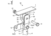
- FIG. 2 is a perspective view of the top of the ceiling fan according to the first embodiment as viewed from the first connection plate side.
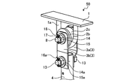
- FIG. 3 is a perspective view of the top of the ceiling fan according to the first embodiment as viewed from the second connection plate side.
- the roller 2 is formed with a through hole 2a coaxial with the central axis. Further, on the outer peripheral surface 2 b of the roller 2, a groove 2 c in which the U-shaped portion 1 a of the fixing bracket 1 is fitted is formed.
- the connection plate 3 has a first connection plate 3a provided with a throttling portion 11 having a shape along the side surface of the pipe 4 and a second connection plate 3b which is a flat plate provided with a notch 12 at one end.
- the throttling portion 11 is formed in a portion fixed to the pipe 4 of the first connection plate 3a.
- the notch portion 12 is formed with a notch in the width direction of the second connection plate 3 b.
- the through hole 19 is formed at the other end side of the second connection plate 3 b.
- the first connecting plate 3a has two holes, an upper through hole 20 and a lower through hole 21.
- the distance between the center of the upper through hole 20 and the center of the lower through hole 21 is the same as the distance between the center in the width direction of the notch 12 and the center of the through hole 19.
- the first connection plate 3 a has a hooking portion 9 at the top.
- the upper through hole 20 is formed at a position overlapping the through hole 2 a of the roller 2 in a state in which the hook portion 9 is hooked to the upper edge of the roller 2.
- the first connecting plate 3a and the second connecting plate 3b Prior to the work of installing the ceiling fan 50 on the ceiling 18, the first connecting plate 3a and the second connecting plate 3b make the lower through hole 21 of the first connecting plate 3a and the upper portion of the pipe 4 orthogonal to the axis of the pipe 4
- the bolt 13 is passed through the through hole penetrating in the direction, the through hole 19 of the second connection plate 3 b, the washer 14 a and the nut 15 a in this order, and the nut 15 a is fastened to the bolt 13.
- the first connection plate 3 a includes the throttling portion 11 having a shape corresponding to the side surface of the pipe 4. Therefore, the alignment between the first connection plate 3a and the pipe 4 can be easily performed.
- the bolt 13 has a through hole 22 penetrating in a direction orthogonal to the axial direction.
- the split pin 16 a is passed through the through hole 22.
- the bolt 13 may pass through the through hole 19 of the second connection plate 3b, the through hole of the pipe 4, the lower through hole 21 of the first connection plate 3a, the washer 14a and the nut 15a in this order.
- the flat second connection plate 3 b is rotatable around the bolt 13 in a state where the nut 15 a is fastened to the bolt 13.
- the first connection plate 3a provided with the narrowed portion 11 having a shape corresponding to the side surface of the pipe 4 can not rotate the bolt 13 as an axis in a state where the nut 15a is fastened to the bolt 13.
- the fixing bracket 1 When the ceiling fan 50 is installed on the ceiling 18, the fixing bracket 1 is fixed to the ceiling 18. Further, the pipe 5 is connected to the main body 5 to which the rotary wings 25 are attached. The pipe 4 is sandwiched between the first connection plate 3a and the second connection plate 3b, and the second connection plate 3b is rotatably fixed to the pipe 4. Then, the groove 2 c is fitted into the U-shaped portion 1 a, and the roller 2 is attached to the fixing bracket 1. By engaging the hook portion 9 with the upper portion of the roller 2, the position of the upper through hole 20 and the through hole 2 a of the roller 2 can be easily aligned.
- the ceiling fan 50 can be temporarily fixed, and the workability of the installation work of the ceiling fan 50 on the ceiling 18 is improved.
- the U-shaped portion 1a is fitted in the groove 2c formed in the outer peripheral surface 2b of the roller 2. Therefore, even if the hook portion 9 is hooked on the roller 2 and the ceiling fan 50 is temporarily fixed, the roller 2 is the fixing bracket 1 Do not drop out of
- FIG. 4 is a perspective view of the upper portion of the ceiling fan according to the first embodiment in a state in which a second connection plate is engaged with a bolt.
- the first connection plate 3 a and the second connection plate 3 b are connected to the roller 2 by bolts 8.
- the second connection plate 3b Since the second connection plate 3b has the notch 12, it is cut even after passing the bolt 8 through the through hole 2a of the roller 2 by rotating the bolt 13 passed through the lower through hole 21 as a rotation axis and rotating it.
- the bolt 8 can be engaged with the notch 12.
- the washer 14 With the bolt 8 engaged with the notch 12, the washer 14 is passed through the bolt 8 and the nut 15 is fastened, whereby the first connection plate 3 a and the second connection plate 3 b are fixed to the roller 2.
- the rotary wing 25 By fixing the first connection plate 3 a and the second connection plate 3 b to the roller 2, the rotary wing 25, the main body 5 and the pipe 4 are fixed to the fixing bracket 1.
- FIG. 5 is a perspective view of the upper part of the ceiling fan according to the first embodiment installed on the ceiling. As shown in FIG. 5, after fixing the bolt 8 penetrating the connection plate 3 with the washer 14 and the nut 15, the installation of the ceiling fan 50 is completed by inserting the locking pin 16 for locking into the hole 17.
- the ceiling fan 50 includes the steps of hooking the first connection plate 3a to the roller 2, rotating the bolt 8 through the first connection plate 3a and the roller 2, and rotating the second connection plate 3b. Since the step of engaging the notch 12 with the bolt 8 is provided, the installation work is excellent, and a highly reliable installation work can be performed even at high places.
- the configuration shown in the above embodiment shows an example of the contents of the present invention, and can be combined with another known technique, and one of the configurations is possible within the scope of the present invention. Parts can be omitted or changed.
- Reference Signs List 1 fixing bracket, 1a U-shaped portion, 2 rollers, 2a, 19 and 22 through holes, 2b outer peripheral surface, 2c groove, 3 connecting plate, 3a first connecting plate, 3b second connecting plate, 4 pipe, 5 main body, 6 wing mounting plate, 7 wings, 8, 13 bolts, 9 hooks, 11 throttles, 12 notches, 14, 14a washers, 15, 15a nuts, 16, 16a split pins, 17 holes, 18 ceilings, 20 top Through hole, 21 lower through hole, 25 rotors, 26 motors, 27 power lines, 50 ceiling fans.
Landscapes
- Engineering & Computer Science (AREA)
- General Engineering & Computer Science (AREA)
- Mechanical Engineering (AREA)
- Structures Of Non-Positive Displacement Pumps (AREA)
Abstract
天井扇(50)は、天井に固定される固定金具(1)と、固定金具(1)に取り付けられるローラ(2)と、ローラ(2)に吊り下げられるパイプ(4)と、電動機(26)を備え、パイプ(4)に連結される本体(5)と、電動機(26)によって回転駆動される回転翼(25)と、パイプに回転不能に固定される第1連結板及びパイプ(4)に回転可能に固定される第2連結板を有し、ローラ(2)とパイプ(4)とを連結する連結板(3)と、第1連結板と第2連結板とでローラ(2)を挟んで固定するボルト(8)とを備え、第2連結板は、ボルト(8)に係合する切り欠き部が形成されている。
Description
本発明は、天井に設置されて床面に向かって気流を送る天井扇及び天井扇の設置方法に関する。
特許文献1に開示される天井扇は、天井固定される固定金具と、固定金具に取り付けられる吊り下げ部と、吊り下げ部に吊り下げられるパイプと、パイプに締結される本体とから構成され、パイプと本体とがボルト及びナットによって締結される。
特許文献1に開示される天井扇は、天井に固定された固定金具に取り付けるとき、固定金具と吊り下げ部をボルトとナットとで締結する構造となっている。特許文献1に開示される天井扇は、高所である天井で設置作業を一人で行う場合、片手で本体を保持しながら、固定金具と吊り下げ部とをボルトとナットとで締結する作業を行う必要がある。したがって、特許文献1に開示される天井扇は、施工性を改善する余地がある。
本発明は、上記に鑑みてなされたものであって、高所における設置作業を一人で行う場合の施工性が高い天井扇を得ることを目的とする。
上述した課題を解決し、目的を達成するために、本発明は、天井に固定される固定金具と、固定金具に取り付けられるローラと、ローラに吊り下げられるパイプと、電動機を備え、パイプに連結される本体と、電動機によって回転駆動される回転翼とを有する。本発明は、パイプに回転不能に固定される第1連結板及びパイプに回転可能に固定される第2連結板を有し、ローラとパイプとを連結する連結板と、第1連結板と第2連結板とでローラを挟んで固定するボルトとを備える。第2連結板は、ボルトに係合する切り欠き部が形成されている。
本発明に係る天井扇は、高所における設置作業を一人で行う場合の施工性が高いという効果を奏する。
以下に、本発明の実施の形態に係る天井扇及び天井扇の設置方法を図面に基づいて詳細に説明する。なお、この実施の形態によりこの発明が限定されるものではない。
実施の形態1.
図1は、本発明の実施の形態1に係る天井扇の側面図である。図1に示すように、天井扇50は、U字形状部1aを備え天井18に固定される固定金具1と、固定金具1に取り付けられるゴム製のローラ2と、ローラ2に連結される連結板3と、連結板3によって吊り下げられるパイプ4と、パイプ4に連結される本体5を有している。本体5の下部には、回転翼25が取り付けられている。回転翼25は、本体5に接続されるボウル形状の羽根取付板6と、羽根取付板6に取り付けられて水平方向に延びる複数の羽根7とを有する。
図1は、本発明の実施の形態1に係る天井扇の側面図である。図1に示すように、天井扇50は、U字形状部1aを備え天井18に固定される固定金具1と、固定金具1に取り付けられるゴム製のローラ2と、ローラ2に連結される連結板3と、連結板3によって吊り下げられるパイプ4と、パイプ4に連結される本体5を有している。本体5の下部には、回転翼25が取り付けられている。回転翼25は、本体5に接続されるボウル形状の羽根取付板6と、羽根取付板6に取り付けられて水平方向に延びる複数の羽根7とを有する。
本体5の内部には、回転翼25を駆動する電動機26が収容されている。電動機26の電源線27は、パイプ4を通って天井18に引き込まれ、不図示の電源に接続されている。天井扇50は、回転翼25が回転することによって天井面から床面へ送風する。
図2は、実施の形態1に係る天井扇の上部を第1連結板側から見た斜視図である。図3は、実施の形態1に係る天井扇の上部を第2連結板側から見た斜視図である。ローラ2は、中心軸と同軸の貫通穴2aが形成されている。また、ローラ2の外周面2bには、固定金具1のU字形状部1aが嵌まる溝2cが形成されている。連結板3は、パイプ4の側面に沿う形状の絞り部11を備えた第1連結板3aと、一端部側に切り欠き部12を備えた平板状である第2連結板3bとを有する。絞り部11は、第1連結板3aのパイプ4に固定される部分に形成されている。切り欠き部12は、第2連結板3bの幅方向に切り欠きが形成されている。第2連結板3bは、他端部側に貫通穴19が形成されている。第1連結板3aは、上部貫通穴20及び下部貫通穴21の二つの穴が開けられている。上部貫通穴20の中心と下部貫通穴21の中心との間隔は、切り欠き部12の切り欠きの幅方向の中央と、貫通穴19の中心との間隔と同じになっている。第1連結板3aは、上部に引っ掛け部9を備える。上部貫通穴20は、引っ掛け部9をローラ2の上部の縁に引っ掛けた状態でローラ2の貫通穴2aと重なる位置に形成されている。
天井扇50を天井18に設置する作業に先立って、第1連結板3a及び第2連結板3bは、第1連結板3aの下部貫通穴21、パイプ4の上部をパイプ4の軸と直交する方向に貫通する貫通穴及び第2連結板3bの貫通穴19、ワッシャ14a及びナット15aの順にボルト13が通され、ナット15aがボルト13に締結される。第1連結板3aは、パイプ4の側面に対応する形状の絞り部11を備えている。したがって、第1連結板3aとパイプ4との位置合わせを容易に行える。ボルト13には、軸方向と直交する方向に貫通する貫通穴22が空けられている。貫通穴22には、割ピン16aが通される。なお、ボルト13は、第2連結板3bの貫通穴19、パイプ4の貫通穴及び第1連結板3aの下部貫通穴21、ワッシャ14a及びナット15aの順に通してもよい。
平板状の第2連結板3bは、ナット15aがボルト13に締結された状態において、ボルト13を軸に回転可能である。一方、パイプ4の側面に対応する形状の絞り部11を備えた第1連結板3aは、ナット15aがボルト13に締結された状態において、ボルト13を軸に回転させることはできない。
天井扇50を天井18に設置する際には、固定金具1が天井18に固定される。また、回転翼25が取り付けられた本体5とパイプ4とを連結する。第1連結板3a及び第2連結板3bとでパイプ4を挟み、第2連結板3bをパイプ4に回動可能に固定する。そして、溝2cがU字形状部1aに嵌め込まれて、ローラ2が固定金具1に取り付けられる。引っ掛け部9をローラ2の上部に係合させることにより、上部貫通穴20とローラ2の貫通穴2aとの位置を容易に合わせることができる。また、引っ掛け部9をローラ2の上部に係合させることにより、天井扇50を仮固定することができ、天井18への天井扇50の設置作業の作業性が向上する。ローラ2の外周面2bに形成された溝2cにU字形状部1aが嵌まっているため、引っ掛け部9をローラ2に引っ掛けて天井扇50を仮固定しても、ローラ2は固定金具1から脱落しない。
次に、第1連結板3aの上部貫通穴20及びローラ2の貫通穴2aの順にボルト8が通される。図4は、実施の形態1に係る天井扇の上部の、第2連結板をボルトに係合させた状態での斜視図である。第1連結板3a及び第2連結板3bは、ボルト8でローラ2に連結される。
第2連結板3bは、切り欠き部12を有するため、下部貫通穴21に通されたボルト13を回転軸にして回転させることにより、ボルト8をローラ2の貫通穴2aに通した後でも切り欠き部12にボルト8を係合させることができる。
切り欠き部12にボルト8を係合させた状態で、ボルト8にワッシャ14を通し、ナット15を締結することで、第1連結板3a及び第2連結板3bがローラ2に固定される。第1連結板3a及び第2連結板3bをローラ2に固定することにより、回転翼25、本体5及びパイプ4は、固定金具1に固定される。
図5は、実施の形態1に係る天井扇の天井に設置した状態での上部の斜視図である。図5に示すように、連結板3を貫通するボルト8をワッシャ14及びナット15で固定した後に、緩み止め用の割ピン16を穴17に通すことで、天井扇50の設置が完了する。
実施の形態1に係る天井扇50は、第1連結板3aをローラ2に引っ掛ける工程と、ボルト8を第1連結板3a及びローラ2の順に貫通させる工程と、第2連結板3bを回転させて切り欠き部12をボルト8に係合させる工程とを有するため、施工性に優れ、高所においても信頼性の高い取り付け工事を行うことができる。
以上の実施の形態に示した構成は、本発明の内容の一例を示すものであり、別の公知の技術と組み合わせることも可能であるし、本発明の要旨を逸脱しない範囲で、構成の一部を省略、変更することも可能である。
1 固定金具、1a U字形状部、2 ローラ、2a,19,22 貫通穴、2b 外周面、2c 溝、3 連結板、3a 第1連結板、3b 第2連結板、4 パイプ、5 本体、6 羽根取付板、7 羽根、8,13 ボルト、9 引っ掛け部、11 絞り部、12 切り欠き部、14,14a ワッシャ、15,15a ナット、16,16a 割ピン、17 穴、18 天井、20 上部貫通穴、21 下部貫通穴、25 回転翼、26 電動機、27 電源線、50 天井扇。
Claims (4)
- 天井に固定される固定金具と、
前記固定金具に取り付けられるローラと、
前記ローラに吊り下げられるパイプと、
電動機を備え、前記パイプに連結される本体と、
前記電動機によって回転駆動される回転翼と、
前記パイプに回転不能に固定される第1連結板及び前記パイプに回転可能に固定される第2連結板を有し、前記ローラと前記パイプとを連結する連結板と、
前記第1連結板と前記第2連結板とで前記ローラを挟んで固定するボルトとを備え、
前記第2連結板は、前記ボルトに係合する切り欠き部が形成されていることを特徴とする天井扇。 - 前記第1連結板は、前記ローラの縁に引っ掛けることが可能な引掛け部を有することを特徴とする請求項1に記載の天井扇。
- 前記第1連結板は、前記パイプに固定される部分に、前記パイプの側面に沿う形状の絞り部が形成されていることを特徴とする請求項1又は2に記載の天井扇。
- 請求項1から3のいずれか1項に記載の天井扇を天井に設置する天井扇の設置方法であって、
前記回転翼が取り付けられた前記本体と前記パイプとを連結する工程と、
前記第1連結板及び前記第2連結板とで前記パイプを挟み、前記第2連結板を前記パイプに回動可能に固定する工程と、
天井に固定された前記固定金具に前記ローラを取り付ける工程と、
前記第1連結板を前記ローラに引っ掛ける工程と、
前記ボルトを前記第1連結板及び前記ローラの順に貫通させる工程と、
前記第2連結板を回転させて前記切り欠き部を前記ボルトに係合させる工程とを有することを特徴とする天井扇の設置方法。
Priority Applications (2)
| Application Number | Priority Date | Filing Date | Title |
|---|---|---|---|
| JP2019561481A JP6783399B2 (ja) | 2017-12-27 | 2017-12-27 | 天井扇の設置方法 |
| PCT/JP2017/046993 WO2019130490A1 (ja) | 2017-12-27 | 2017-12-27 | 天井扇及び天井扇の設置方法 |
Applications Claiming Priority (1)
| Application Number | Priority Date | Filing Date | Title |
|---|---|---|---|
| PCT/JP2017/046993 WO2019130490A1 (ja) | 2017-12-27 | 2017-12-27 | 天井扇及び天井扇の設置方法 |
Publications (1)
| Publication Number | Publication Date |
|---|---|
| WO2019130490A1 true WO2019130490A1 (ja) | 2019-07-04 |
Family
ID=67063316
Family Applications (1)
| Application Number | Title | Priority Date | Filing Date |
|---|---|---|---|
| PCT/JP2017/046993 Ceased WO2019130490A1 (ja) | 2017-12-27 | 2017-12-27 | 天井扇及び天井扇の設置方法 |
Country Status (2)
| Country | Link |
|---|---|
| JP (1) | JP6783399B2 (ja) |
| WO (1) | WO2019130490A1 (ja) |
Citations (4)
| Publication number | Priority date | Publication date | Assignee | Title |
|---|---|---|---|---|
| JPS55149596U (ja) * | 1979-04-12 | 1980-10-28 | ||
| JPS59103897U (ja) * | 1982-12-28 | 1984-07-12 | 松下精工株式会社 | 天井用扇風機 |
| JPS6149096U (ja) * | 1984-09-06 | 1986-04-02 | ||
| JP2015034633A (ja) * | 2014-10-02 | 2015-02-19 | 株式会社昭和コーポレーション | 振れ止め用金具の固定部構造 |
-
2017
- 2017-12-27 JP JP2019561481A patent/JP6783399B2/ja active Active
- 2017-12-27 WO PCT/JP2017/046993 patent/WO2019130490A1/ja not_active Ceased
Patent Citations (4)
| Publication number | Priority date | Publication date | Assignee | Title |
|---|---|---|---|---|
| JPS55149596U (ja) * | 1979-04-12 | 1980-10-28 | ||
| JPS59103897U (ja) * | 1982-12-28 | 1984-07-12 | 松下精工株式会社 | 天井用扇風機 |
| JPS6149096U (ja) * | 1984-09-06 | 1986-04-02 | ||
| JP2015034633A (ja) * | 2014-10-02 | 2015-02-19 | 株式会社昭和コーポレーション | 振れ止め用金具の固定部構造 |
Also Published As
| Publication number | Publication date |
|---|---|
| JP6783399B2 (ja) | 2020-11-11 |
| JPWO2019130490A1 (ja) | 2020-04-02 |
Similar Documents
| Publication | Publication Date | Title |
|---|---|---|
| US6872054B2 (en) | Mounting system for supporting a ceiling fan assembly | |
| US11022148B2 (en) | Fan mounting system | |
| JP5950877B2 (ja) | 空気調和機の化粧パネル取付構造及び室内機 | |
| US20080286111A1 (en) | Ceiling fan hanging system | |
| US20150086375A1 (en) | Ceiling fan | |
| WO2019130490A1 (ja) | 天井扇及び天井扇の設置方法 | |
| JP2021193302A (ja) | 天井扇風機 | |
| CN212563710U (zh) | 一种工业大风扇的防脱落装置 | |
| US20170051759A1 (en) | Slide on Flush Mount Bracket with Captive Fasteners | |
| CN204511788U (zh) | 变桨柜的布置结构及风力发电机组 | |
| CN204902174U (zh) | 一种空调室内机以及空调器 | |
| WO2019138483A1 (ja) | 天井扇風機 | |
| JP2018053619A (ja) | ターンバックル及びそれを用いたジェットファンの支持方法 | |
| JP7045524B2 (ja) | 扇風機 | |
| JP3027508U (ja) | 換気ファンの取付け構造 | |
| JP2014152700A (ja) | 天井扇風機 | |
| CN206106873U (zh) | 全液压式工程车空调压缩机简易安装结构 | |
| KR100972158B1 (ko) | 와이어 컨트롤을 이용한 자율이동장치의 와이어 고정장치 | |
| JP6983337B2 (ja) | 天井扇風機 | |
| CN206094304U (zh) | 风叶结构及具有其的空调器 | |
| CN112962835A (zh) | 用于幕墙装配结构的连接组件及连接方法 | |
| CN111997938A (zh) | 风扇吊架及风扇装置 | |
| WO2017128168A1 (zh) | 一种吊顶式空调快速制冷系统 | |
| JP6335060B2 (ja) | 車両用空気調和機 | |
| JP2022057064A (ja) | ジェットファン |
Legal Events
| Date | Code | Title | Description |
|---|---|---|---|
| 121 | Ep: the epo has been informed by wipo that ep was designated in this application |
Ref document number: 17935921 Country of ref document: EP Kind code of ref document: A1 |
|
| ENP | Entry into the national phase |
Ref document number: 2019561481 Country of ref document: JP Kind code of ref document: A |
|
| NENP | Non-entry into the national phase |
Ref country code: DE |
|
| 122 | Ep: pct application non-entry in european phase |
Ref document number: 17935921 Country of ref document: EP Kind code of ref document: A1 |