WO2019116938A1 - ろ過膜の洗浄方法 - Google Patents
ろ過膜の洗浄方法 Download PDFInfo
- Publication number
- WO2019116938A1 WO2019116938A1 PCT/JP2018/044336 JP2018044336W WO2019116938A1 WO 2019116938 A1 WO2019116938 A1 WO 2019116938A1 JP 2018044336 W JP2018044336 W JP 2018044336W WO 2019116938 A1 WO2019116938 A1 WO 2019116938A1
- Authority
- WO
- WIPO (PCT)
- Prior art keywords
- cleaning
- filtration membrane
- liquid
- washing
- treated
- Prior art date
- Legal status (The legal status is an assumption and is not a legal conclusion. Google has not performed a legal analysis and makes no representation as to the accuracy of the status listed.)
- Ceased
Links
Images


Classifications
-
- B—PERFORMING OPERATIONS; TRANSPORTING
- B01—PHYSICAL OR CHEMICAL PROCESSES OR APPARATUS IN GENERAL
- B01D—SEPARATION
- B01D65/00—Accessories or auxiliary operations, in general, for separation processes or apparatus using semi-permeable membranes
- B01D65/02—Membrane cleaning or sterilisation ; Membrane regeneration
- B01D65/06—Membrane cleaning or sterilisation ; Membrane regeneration with special washing compositions
-
- B—PERFORMING OPERATIONS; TRANSPORTING
- B01—PHYSICAL OR CHEMICAL PROCESSES OR APPARATUS IN GENERAL
- B01D—SEPARATION
- B01D65/00—Accessories or auxiliary operations, in general, for separation processes or apparatus using semi-permeable membranes
- B01D65/02—Membrane cleaning or sterilisation ; Membrane regeneration
-
- B—PERFORMING OPERATIONS; TRANSPORTING
- B01—PHYSICAL OR CHEMICAL PROCESSES OR APPARATUS IN GENERAL
- B01D—SEPARATION
- B01D61/00—Processes of separation using semi-permeable membranes, e.g. dialysis, osmosis or ultrafiltration; Apparatus, accessories or auxiliary operations specially adapted therefor
- B01D61/14—Ultrafiltration; Microfiltration
- B01D61/22—Controlling or regulating
-
- C—CHEMISTRY; METALLURGY
- C02—TREATMENT OF WATER, WASTE WATER, SEWAGE, OR SLUDGE
- C02F—TREATMENT OF WATER, WASTE WATER, SEWAGE, OR SLUDGE
- C02F1/00—Treatment of water, waste water, or sewage
- C02F1/44—Treatment of water, waste water, or sewage by dialysis, osmosis or reverse osmosis
-
- C—CHEMISTRY; METALLURGY
- C02—TREATMENT OF WATER, WASTE WATER, SEWAGE, OR SLUDGE
- C02F—TREATMENT OF WATER, WASTE WATER, SEWAGE, OR SLUDGE
- C02F3/00—Biological treatment of water, waste water, or sewage
- C02F3/006—Regulation methods for biological treatment
-
- C—CHEMISTRY; METALLURGY
- C02—TREATMENT OF WATER, WASTE WATER, SEWAGE, OR SLUDGE
- C02F—TREATMENT OF WATER, WASTE WATER, SEWAGE, OR SLUDGE
- C02F3/00—Biological treatment of water, waste water, or sewage
- C02F3/02—Aerobic processes
- C02F3/12—Activated sludge processes
- C02F3/1236—Particular type of activated sludge installations
- C02F3/1268—Membrane bioreactor systems
- C02F3/1273—Submerged membrane bioreactors
-
- B—PERFORMING OPERATIONS; TRANSPORTING
- B01—PHYSICAL OR CHEMICAL PROCESSES OR APPARATUS IN GENERAL
- B01D—SEPARATION
- B01D2311/00—Details relating to membrane separation process operations and control
- B01D2311/10—Temperature control
-
- B—PERFORMING OPERATIONS; TRANSPORTING
- B01—PHYSICAL OR CHEMICAL PROCESSES OR APPARATUS IN GENERAL
- B01D—SEPARATION
- B01D2311/00—Details relating to membrane separation process operations and control
- B01D2311/14—Pressure control
-
- B—PERFORMING OPERATIONS; TRANSPORTING
- B01—PHYSICAL OR CHEMICAL PROCESSES OR APPARATUS IN GENERAL
- B01D—SEPARATION
- B01D2315/00—Details relating to the membrane module operation
- B01D2315/06—Submerged-type; Immersion type
-
- B—PERFORMING OPERATIONS; TRANSPORTING
- B01—PHYSICAL OR CHEMICAL PROCESSES OR APPARATUS IN GENERAL
- B01D—SEPARATION
- B01D2315/00—Details relating to the membrane module operation
- B01D2315/20—Operation control schemes defined by a periodically repeated sequence comprising filtration cycles combined with cleaning or gas supply, e.g. aeration
-
- B—PERFORMING OPERATIONS; TRANSPORTING
- B01—PHYSICAL OR CHEMICAL PROCESSES OR APPARATUS IN GENERAL
- B01D—SEPARATION
- B01D2321/00—Details relating to membrane cleaning, regeneration, sterilization or to the prevention of fouling
- B01D2321/16—Use of chemical agents
- B01D2321/162—Use of acids
-
- B—PERFORMING OPERATIONS; TRANSPORTING
- B01—PHYSICAL OR CHEMICAL PROCESSES OR APPARATUS IN GENERAL
- B01D—SEPARATION
- B01D2321/00—Details relating to membrane cleaning, regeneration, sterilization or to the prevention of fouling
- B01D2321/16—Use of chemical agents
- B01D2321/164—Use of bases
-
- B—PERFORMING OPERATIONS; TRANSPORTING
- B01—PHYSICAL OR CHEMICAL PROCESSES OR APPARATUS IN GENERAL
- B01D—SEPARATION
- B01D61/00—Processes of separation using semi-permeable membranes, e.g. dialysis, osmosis or ultrafiltration; Apparatus, accessories or auxiliary operations specially adapted therefor
- B01D61/58—Multistep processes
-
- C—CHEMISTRY; METALLURGY
- C02—TREATMENT OF WATER, WASTE WATER, SEWAGE, OR SLUDGE
- C02F—TREATMENT OF WATER, WASTE WATER, SEWAGE, OR SLUDGE
- C02F2209/00—Controlling or monitoring parameters in water treatment
- C02F2209/02—Temperature
-
- C—CHEMISTRY; METALLURGY
- C02—TREATMENT OF WATER, WASTE WATER, SEWAGE, OR SLUDGE
- C02F—TREATMENT OF WATER, WASTE WATER, SEWAGE, OR SLUDGE
- C02F2209/00—Controlling or monitoring parameters in water treatment
- C02F2209/03—Pressure
-
- C—CHEMISTRY; METALLURGY
- C02—TREATMENT OF WATER, WASTE WATER, SEWAGE, OR SLUDGE
- C02F—TREATMENT OF WATER, WASTE WATER, SEWAGE, OR SLUDGE
- C02F2303/00—Specific treatment goals
- C02F2303/16—Regeneration of sorbents, filters
-
- Y—GENERAL TAGGING OF NEW TECHNOLOGICAL DEVELOPMENTS; GENERAL TAGGING OF CROSS-SECTIONAL TECHNOLOGIES SPANNING OVER SEVERAL SECTIONS OF THE IPC; TECHNICAL SUBJECTS COVERED BY FORMER USPC CROSS-REFERENCE ART COLLECTIONS [XRACs] AND DIGESTS
- Y02—TECHNOLOGIES OR APPLICATIONS FOR MITIGATION OR ADAPTATION AGAINST CLIMATE CHANGE
- Y02W—CLIMATE CHANGE MITIGATION TECHNOLOGIES RELATED TO WASTEWATER TREATMENT OR WASTE MANAGEMENT
- Y02W10/00—Technologies for wastewater treatment
- Y02W10/10—Biological treatment of water, waste water, or sewage
Definitions
- the present invention relates to a method of cleaning a filtration membrane provided in a membrane filtration apparatus which is immersed in a liquid to be treated to separate the liquid to be treated in solid-liquid separation.
- a membrane filtration apparatus is used to perform solid-liquid separation of a liquid to be treated.
- the membrane filtration device is immersed in the liquid to be treated and has a filtration membrane.
- suspended matter, suspended matter and the like adhere or deposit on the membrane surface and in the membrane, and clogging of the filtration membrane occurs.
- the pressure difference between the treated liquid side (i.e., the primary side) and the permeated water side (i.e., the secondary side) of the filtration membrane that is, the transmembrane pressure difference increases. If the transmembrane differential pressure is increased, the permeation flux is reduced, and the throughput of the liquid to be treated can not be stably secured.
- the filtration membrane is cleaned using a chemical solution.
- the transmembrane pressure difference immediately after resuming the filtration after washing the filtration membrane is measured, and the degree of washing is determined based on the measured value of the transmembrane pressure.
- the concentration of the chemical solution and the cleaning time are determined based on the degree of cleaning.
- the degree of washing is determined based on the measured value of the transmembrane pressure difference, and the filtration membrane is washed with the concentration of the chemical solution and the washing time corresponding to the determined degree of washing.
- the concentration of the chemical solution and the cleaning time are adjusted based on the measured value of the transmembrane differential pressure, the concentration and the cleaning time of the chemical solution according to the degree of clogging of the filtration membrane And the filtration membrane can be washed.
- the method of adjusting the degree of cleaning of the filtration membrane as described above is not only based on the value of the transmembrane pressure, but also largely depends on the temperature of the liquid to be treated in which the membrane filtration apparatus is immersed. For example, when the temperature of the liquid to be treated is low, the washing speed decreases, so even if the washing degree is the same (chemical solution concentration, washing time), the washing of the filtration membrane becomes insufficient, and even if the washing There is a possibility that pressure does not recover sufficiently. In addition, when the temperature of the liquid to be treated is high, the washing rate is increased, so even if the washing degree is the same, the filtration membrane is excessively washed, which reduces the power and cost required to wash the filtration membrane. It becomes difficult.
- the present invention is to provide an efficient filtration membrane cleaning method which prevents the cleaning from becoming insufficient and the cleaning from becoming excessive depending on the temperature of the liquid to be treated, with little waste. To aim.
- the first aspect of the method for cleaning a filtration membrane according to the present invention which is included in a membrane filtration apparatus which is immersed in a liquid to be treated to perform solid-liquid separation of the liquid to be treated, If the transmembrane pressure difference exceeds the first predetermined differential pressure, a first cleaning step of cleaning the filtration membrane is performed using the first chemical solution, When the transmembrane differential pressure immediately after the first cleaning step exceeds a second predetermined differential pressure lower than the first predetermined differential pressure, a second chemical solution whose concentration is higher than that of the first chemical solution, and And / or performing a second washing step of washing the filtration membrane with a washing time longer than the first washing step, When performing the second cleaning step, the concentration of the second chemical solution and / or the cleaning time of the second cleaning step are changed according to the temperature of the liquid to be treated.
- the filtration membrane is normally washed by stopping the membrane filtration and performing the first washing step. Washed with degree. As a result, the deposits and the like on the membrane surface are removed, and the transmembrane pressure difference when membrane filtration is resumed immediately after the first washing step is lower than that immediately before the first washing step. When such membrane filtration and the first washing step are repeated, the amount of deposits remaining on the filtration membrane is not gradually removed, and therefore, the membrane filtration is resumed immediately after the first washing step.
- the 2nd washing process is performed.
- the filtration membrane is cleaned using the second chemical solution whose concentration is higher than that of the first chemical solution and / or in the cleaning time longer than the first cleaning process, so the filtration membrane is strongly cleaned. can do.
- the concentration of the second chemical solution and / or the cleaning time of the second cleaning step is changed according to the temperature of the liquid to be treated according to the temperature of the liquid to be treated Since the filtration membrane is washed with the optimal chemical concentration and / or washing time, the washing of the filtration membrane may be insufficient, the consumption of the chemical solution may be increased more than necessary, or the washing time may be longer than necessary. Can be prevented, and the power and cost required to wash the filtration membrane can be reduced. This makes it possible to wash the filtration membrane with little waste and efficiency.
- the second aspect of the filtration membrane cleaning method of the present invention is a value obtained by dividing the transmembrane pressure immediately after the second washing step by the transmembrane pressure immediately after the second washing step performed one time before.
- a third cleaning step of cleaning the filtration membrane using a third chemical solution different from the first and second chemical solutions is performed.
- the transmembrane pressure immediately after the second washing step is once The value divided by the transmembrane pressure immediately after the second cleaning step performed previously exceeds the predetermined ratio.
- the third washing step of washing the filtration membrane using the third chemical solution suitable for removing the adhesion of another nature the adhesion of another nature adhering to the filtration membrane is also It can be sufficiently removed.
- the third aspect of the method for cleaning a filtration membrane according to the present invention which is included in a membrane filtration apparatus which is immersed in a liquid to be treated to perform solid-liquid separation of the liquid to be treated,
- a first cleaning step of cleaning the filtration membrane is performed using a first chemical solution
- the concentration of the second chemical solution and / or the cleaning time of the second cleaning step are changed according to the temperature of the liquid to be treated.
- the filtration membrane is usually cleaned by stopping the membrane filtration and performing the first washing step. Washed with strength. As a result, the deposit and the like on the membrane surface are removed, and the permeation performance when membrane filtration is resumed immediately after the first washing step is higher than that immediately before the first washing step.
- the amount of deposits remaining on the filtration membrane is not gradually removed, and therefore, the membrane filtration is resumed immediately after the first washing step.
- the concentration of the second chemical solution and / or the cleaning time of the second cleaning step is changed according to the temperature of the liquid to be treated according to the temperature of the liquid to be treated Since the filtration membrane is washed with the optimal chemical concentration and / or washing time, the washing of the filtration membrane may be insufficient, the consumption of the chemical solution may be increased more than necessary, or the washing time may be longer than necessary. Can be prevented, and the power and cost required to wash the filtration membrane can be reduced. This makes it possible to wash the filtration membrane with little waste and efficiency.
- a value obtained by dividing the permeation performance immediately after the second cleaning step by the permeation performance immediately after the second cleaning step performed one time is lower than a predetermined ratio
- a third cleaning step of cleaning the filtration membrane using a third chemical solution different from the first and second chemical solutions is performed.
- the permeation performance immediately after the second washing step is made once.
- the value divided by the permeation performance immediately after the second washing step performed is less than the predetermined ratio.
- the filtration membrane cleaning method of the present invention when the second cleaning step is performed, the higher the temperature of the liquid to be treated, the lower the concentration of the second chemical solution, and the lower the temperature of the liquid to be treated The concentration of the second chemical solution is increased. According to this, when performing the second cleaning step, the filtration membrane is cleaned with the optimum concentration of the second chemical solution according to the temperature of the liquid to be treated.
- a filtration membrane is wash
- the first chemical solution and the second chemical solution remove organic-based adhesions adhering to the filtration membrane. According to this, by performing the first cleaning step and the second cleaning step using the first chemical solution and the second chemical solution, it is possible to sufficiently remove the organic-based adhering matter adhering to the filtration membrane. .
- the filtration membrane is cleaned at the optimum concentration of the third chemical solution according to the temperature of the liquid to be treated.
- the ninth aspect of the filtration membrane cleaning method of the present invention shortens the cleaning time as the temperature of the liquid to be treated is higher when the third cleaning step is performed, and the cleaning time is longer as the temperature of the liquid to be treated is lower. It is According to this, when performing a 3rd washing process, a filtration membrane is wash
- the third chemical solution is to remove an inorganic substance attached to the filtration membrane. According to this, by performing the third cleaning step using the third chemical solution, it is possible to sufficiently remove the inorganic-based deposits attached to the filtration membrane.
- 1 is an activated sludge treatment tank, and a supply system 4 for supplying organic drainage is in communication with the upper portion of the tank main body 2.
- a discharge system 5 for discharging excess sludge is in communication with the lower part of.
- the liquid to be treated 3 is stored in the tank main body 2, and a soaking type membrane filtration apparatus 6 and a temperature measuring device 20 for measuring the temperature of the liquid to be treated 3 are provided.
- the liquid 3 to be treated is a mixture of organic drainage and activated sludge, and the organic drainage is, for example, sewage, manure, factory drainage, and the like.
- the membrane filtration apparatus 6 has a box-like casing 7 which is open at the top and bottom, and a plurality of flat membrane elements 8 arranged in the casing 7.
- the flat sheet membrane elements 8 are arranged parallel to each other along the vertical direction.
- the flat membrane element 8 has a filter plate 9 and a sheet-like filtration membrane 10 joined to both sides of the filter plate 9. Permeate channels are formed between the filter plate 9 and the filtration membrane 10 and in the filter plate 9. A permeate outlet 11 communicating with the permeate channel is provided at the upper end edge of the filter plate 9. The permeated liquid that has permeated through the filtration membrane 10 is taken out from the permeated liquid outlet 11 through the permeated liquid flow path.
- Each flat membrane element 8 is in communication with the water collection pipe 13 via a tube 12 connected to the permeate outlet 11.
- a permeated liquid discharge path 14 for discharging the permeated liquid is connected to the water collection pipe 13.
- a permeated liquid outlet valve 15 and a suction pump 16 are provided in the permeated liquid outlet path 14.
- a diffuser 17 is installed below the array of flat membrane elements 8. The air diffuser 17 is provided with a blower 19 via an air supply pipe 18.
- the activated sludge treatment tank 1 is equipped with a membrane cleaning device 22 for cleaning the filtration membrane 10 of each flat membrane element 8.
- the film cleaning apparatus 22 includes a first chemical solution storage tank 24 (an example of a first chemical solution reservoir) for storing sodium hypochlorite solution 23 (an example of first and second chemical solutions), and a citric acid solution 26.
- a second chemical liquid storage tank 27 (an example of a second chemical liquid storage section) that stores (an example of a third chemical liquid) and a dilution liquid storage tank 30 (an example of a dilution liquid storage section) that stores a dilution liquid 29
- a chemical solution supply path 31 connected to the permeated liquid discharge path 14; a first chemical solution supply device 33 for supplying the sodium hypochlorite solution 23 in the first chemical solution storage tank 24 to the chemical solution supply path 31;
- the second chemical liquid supply device 34 that supplies the citric acid solution 26 in the chemical liquid storage tank 27 to the chemical liquid supply path 31 and the dilution liquid supply that supplies the diluted liquid 29 in the dilution liquid storage tank 30 to the chemical liquid supply path 31
- Device 35, static mixer 37 (an example of a chemical-liquid mixing apparatus), and a chemical liquid supply valve 38.
- the chemical solution supply path 31 is connected between the water collecting pipe 13 and the permeated liquid outlet valve 15 in the permeated liquid outlet path 14.
- the static mixer 37 and the chemical solution supply valve 38 are provided in the chemical solution supply path 31.
- the first and second chemical liquid supply devices 33 and 34 and the dilution liquid supply device 35 are respectively constituted by a valve, a supply pump and the like.
- the static mixer 37 mixes the sodium hypochlorite solution 23 with the diluent 29 to adjust the concentration of the sodium hypochlorite solution 23, and mixes the citric acid solution 26 and the diluent 29 with citric acid. And the function of adjusting the concentration of the acid solution 26.
- the sodium hypochlorite solution 23 has the ability to remove the deposit made of the organic matter attached to the filtration membrane 10.
- the citric acid solution 26 has the ability to remove deposits made of inorganic matter attached to the filtration membrane 10.
- the permeated liquid outlet path 40 is connected to a permeated liquid outlet path 40 for taking out part of the permeated liquid flowing through the permeated liquid outlet path 14 and supplying it to the diluted liquid storage tank 30. Thereby, a part of the permeated fluid flowing through the permeated fluid outlet path 14 is supplied from the permeated fluid outlet path 40 to the diluent reservoir tank 30 and used as the diluent 29.
- a permeated liquid outlet valve 41 is provided in the permeated liquid outlet path 40.
- the chemical solution supply valve 38 is closed, the permeated liquid outlet valve 15 is opened, and the suction pump 16 and the blower 19 are operated.
- a large number of air bubbles are released from the air diffuser 17 and rise between the flat sheet membrane elements 8, and the liquid 3 to be treated passes through the filtration membranes 10 of the flat sheet elements 8 and is filtered.
- transmitted the filtration membrane 10 flows into the water collection pipe 13 through the tube 12 of each flat membrane element 8 as a permeated liquid, flows from the water collection pipe 13 through the permeated liquid discharge path 14, and is taken out of system.
- sodium hypochlorite solution 23 (the first chemical solution) having a predetermined concentration C0 (for example, a concentration of about several percent by weight) at normal cleaning degree A
- a predetermined concentration C0 for example, a concentration of about several percent by weight
- the filtration membrane 10 is washed for a first washing time T1 using one example).
- the suction pump 16 and the blower 19 are stopped, the permeated liquid outlet valve 15 is closed, the chemical solution supply valve 38 is opened, and the first chemical solution is The supply device 33 and the diluent supply device 35 are operated.
- a predetermined amount of sodium hypochlorite solution 23 is supplied from the first liquid chemical storage tank 24 to the static mixer 37 through the chemical liquid supply path 31, and a predetermined amount of dilution liquid 29 is diluted water storage tank 30.
- the solution is supplied to the static mixer 37 through the chemical solution supply path 31.
- the sodium hypochlorite solution 23 is mixed with the diluent 29 and adjusted to a predetermined concentration C0.
- sodium hypochlorite solution 23 having a predetermined concentration C0 is supplied from the chemical solution supply path 31 to the inside of each flat sheet membrane element 8 through the permeated liquid lead-out path 14, the water collection pipe 13 and the tube 12 to be a filtration membrane.
- the filtration membrane 10 is washed with the sodium hypochlorite solution 23, and the deposits on the filtration membrane 10 are removed.
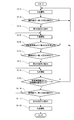
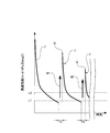
- the transmembrane pressure difference S when the filtration operation F is restarted immediately after the step is gradually increased.
- the transmembrane differential pressure S when the filtration operation F is resumed immediately after performing the first cleaning step W1 as described above is referred to as an initial transmembrane differential pressure S.
- the subsequent inter-membrane differential pressure is the first predetermined
- the differential pressure P1 is exceeded (S-6)
- the filtration operation F is temporarily stopped, and the sodium hypochlorite solution 23 is used to wash the filtration membrane 10 with a washing degree B1 to B5 higher than the normal washing degree A.
- a second cleaning step W2 is performed (S-7).
- the second predetermined differential pressure P2 is set to be lower than the first predetermined differential pressure P1.
- the cleaning time in the second cleaning step W2 is set to a second cleaning time T2 longer than the first cleaning time T1.
- the cleaning degrees B1 to B5 in the second cleaning step W2 are set to five stages (a plurality of stages) in accordance with the temperature of the liquid to be treated 3 measured by the temperature measuring device 20. There is. For example, when the temperature of the liquid 3 to be treated is less than D1 [° C.], the first washing degree B1 is selected, and the concentration of the sodium hypochlorite solution 23 is set to a predetermined high concentration C1.
- the second washing degree B2 is selected, and the concentration of the sodium hypochlorite solution 23 is a predetermined high concentration C2 Set to
- the third washing degree B3 is selected, and the concentration of the sodium hypochlorite solution 23 is a predetermined high concentration C3.
- the fourth washing degree B4 is selected, and the concentration of the sodium hypochlorite solution 23 is a predetermined high concentration C4.
- the temperature of the liquid 3 to be treated is D4 [° C.] or more
- the fifth cleaning degree B5 is selected, and the concentration of the sodium hypochlorite solution 23 is set to a predetermined high concentration C5.
- the predetermined high concentrations C1 to C5 of the sodium hypochlorite solution 23 (an example of the second chemical solution) in the first to fifth cleaning degrees B1 to B5 of the second cleaning step W2 are the first The concentration is set to a range (for example, a concentration of about several percent by weight sufficient) higher than the predetermined concentration C0 of the sodium hypochlorite solution 23 (an example of the first chemical solution) at the cleaning step W1 of It has a relation of> concentration C2> concentration C3> concentration C4> concentration C5> concentration C0. Further, the temperature of the liquid 3 to be treated is in the relation of “temperature D1 ⁇ temperature D2 ⁇ temperature D3 ⁇ temperature D4”.
- the temperatures D1 to D4 of the liquid 3 to be treated are higher, the concentrations C1 to C5 of the sodium hypochlorite solution 23 are lowered, and the temperatures D1 to D4 of the liquid 3 to be treated Is set to raise the concentration C1 to C5 of the sodium hypochlorite solution 23.
- the second cleaning degree B2 is selected.
- the concentration of the sodium hypochlorite solution 23 is set to a predetermined high concentration C2.
- the sodium hypochlorite solution 23 is mixed with the dilution liquid 29 to be adjusted to a predetermined high concentration C2, and the predetermined low concentration C2 sodium hypochlorite solution 23 is each flat sheet membrane element It is supplied to the inside of 8 and contacts the filtration membrane 10.
- the filtration membrane 10 is strongly cleaned by the sodium hypochlorite solution 23 having a concentration C2 higher than the predetermined concentration C0 in the first cleaning step W1, the deposit on the filtration membrane 10 is strongly removed. Ru.
- the fourth washing degree B4 is selected, and sodium hypochlorite solution
- the concentration of 23 is set to a predetermined high concentration C4, and the filtration membrane 10 is strongly washed with a sodium hypochlorite solution 23 having a concentration C4 higher than the predetermined concentration C0 in the first cleaning step W1.
- the filtration membrane 10 is washed at the concentration of the sodium hypochlorite solution 23 based on the degree of washing for the second washing time T2. For this reason, it is possible to prevent the insufficient cleaning of the filtration membrane 10 and the excessive use of the sodium hypochlorite solution 23 and the cleaning time. As a result, the power and cost required for cleaning the filtration membrane 10 can be reduced, and the filtration membrane 10 can be efficiently cleaned with little waste.
- the sodium hypochlorite solution 23 by using the sodium hypochlorite solution 23, it is possible to sufficiently remove the deposits mainly composed of organic substances from the filtration membrane 10. .
- the inorganic substance slightly contained in the liquid to be treated 3 may adhere to the filtration membrane 10, and the deposit made of the inorganic substance may gradually grow on the membrane surface of the filtration membrane 10. It was difficult to sufficiently remove the deposit of inorganic matter using sodium hypochlorite solution 23.
- the subsequent transmembrane differential pressure is the first If the predetermined differential pressure P1 is exceeded (S-10), the filtration operation F is temporarily stopped, and the third cleaning step W3 (S-11) of cleaning the filtration membrane 10 using the citric acid solution 26 is performed.
- the predetermined ratio Zs is a constant larger than 1, and the value of "the initial transmembrane differential pressure S (n) / one previous previous transmembrane differential pressure S (n-1) " exceeds the predetermined ratio Zs.
- the filtration operation F is temporarily stopped, and the third cleaning step W3 as described below is performed.
- the washing time in the third washing step W3 is set as the third washing time T3, and the third washing time T3 is the same as the first washing time T1.
- a predetermined amount of citric acid solution 26 is supplied from the second chemical solution storage tank 27 to the chemical solution supply path 31 by operating the second chemical solution supply device 34 and the dilution solution supply device 35.
- the predetermined amount of dilution liquid 29 is supplied from the dilution liquid storage tank 30 to the static mixer 37 through the drug solution supply path 31 while being supplied to the static mixer 37, and the citric acid solution 26 is diluted in the static mixer 37.
- the solution is mixed with the solution 29 and adjusted to a predetermined concentration, and a citric acid solution 26 of a predetermined concentration is supplied to the inside of each flat sheet membrane element 8 to contact the filtration membrane 10.
- the filtration membrane 10 is washed with the citric acid solution 26, and the deposit of the inorganic substance is sufficiently removed from the filtration membrane 10.
- the third cleaning process W3 is stopped and the filtration operation F is restarted (S-12).
- the transmembrane pressure difference is lower than that immediately before the third cleaning step W3.
- S-1 to S-12 of the flowchart shown in FIG. 3 are repeated, and when the transmembrane pressure difference exceeds the first predetermined differential pressure P1, the first cleaning process W1 is performed.
- the filtration operation F is temporarily stopped when the subsequent transmembrane differential pressure exceeds the first predetermined differential pressure P1, and the second cleaning step is performed. Repeat doing W2.
- the transmembrane pressure difference exceeds the first predetermined differential pressure P1 the filtration operation F may be temporarily stopped and the third cleaning step W3 may be performed.
- the transmembrane pressure difference of the filtration membrane 10 is used as an index for the first cleaning step W1, the second cleaning step W2, and the third cleaning step.
- the first cleaning steps W1 and W2 are performed using the permeability (Permeability) of the filtration membrane 10 as an indicator in the second embodiment described below.
- the cleaning process W2 and the third cleaning process W3 are performed.
- permeability permeation flux / transmembrane pressure difference
- the filtration membrane 10 is washed for a first washing time T1 using a sodium hypochlorite solution 23 having a predetermined concentration C0.
- the filtration membrane 10 is washed with the sodium hypochlorite solution 23, and the deposits on the filtration membrane 10 are removed.
- the first cleaning step W1 is stopped and the filtration operation F is restarted (S-4). Immediately after resumption of the filtration operation F, since the attached matter is removed from the filtration membrane 10, the permeation performance is higher than that immediately before the first cleaning step W1.
- the permeation performance Q at the time of resuming the filtration operation F gradually decreases.
- the permeation performance Q when the filtration operation F is resumed immediately after performing the first cleaning step W1 as described above is referred to as an initial permeation performance Q.
- the cleaning degrees B1 to B5 in the second cleaning step W2 are set to five stages (a plurality of stages) according to the temperature of the liquid to be treated 3 measured by the temperature measuring device 20. There is.
- the second cleaning degree B3 is selected.
- the concentration of the sodium hypochlorite solution 23 is set to a predetermined high concentration C3.
- the sodium hypochlorite solution 23 is mixed with the dilution liquid 29 and adjusted to a predetermined high concentration C3, and the predetermined high concentration C3 sodium hypochlorite solution 23 is each flat sheet membrane element It is supplied to the inside of 8 and contacts the filtration membrane 10.
- the filtration membrane 10 is strongly cleaned by the sodium hypochlorite solution 23 having a concentration C3 higher than the predetermined concentration C0 in the first cleaning step W1, so that the deposit on the filtration membrane 10 is strongly removed. Ru.
- the filtration membrane 10 is washed at the concentration of the sodium hypochlorite solution 23 based on the degree of washing for the second washing time T2. For this reason, it is possible to prevent the insufficient cleaning of the filtration membrane 10 and the excessive use of the sodium hypochlorite solution 23 and the cleaning time. As a result, the power and cost required for cleaning the filtration membrane 10 can be reduced, and the filtration membrane 10 can be efficiently cleaned with little waste.
- the ratio of the immediately following initial permeability Q (n) than this immediately after the second cleaning step W2 taken before once also initial permeability Q (n-1) of the wash step W2 decreases.
- the ratio between the initial transmission performance Q (n) and the initial transmission performance Q (n-1) falls below the predetermined ratio Zq (S-9)
- the subsequent transmission performance falls below the first transmission performance L1.
- the filtration operation F is temporarily stopped, and the third cleaning step W3 of cleaning the filtration membrane 10 using the citric acid solution 26 is performed (S-11).
- the predetermined ratio Zq is a constant smaller than 1, and when the value of “initial transmission performance Q (n) / initial transmission performance Q (n ⁇ 1) before 1 time” falls below the predetermined ratio Zq, When the permeation performance falls below the first permeation performance L1, the filtration operation F is temporarily stopped, and a third cleaning step W3 as described below is performed.
- the washing time in the third washing step W3 is set as the third washing time T3, and the third washing time T3 is the same as the first washing time T1.
- citric acid solution 26 of a predetermined concentration is supplied to the inside of each flat sheet membrane element 8 to contact the filtration membrane 10.
- the filtration membrane 10 is washed with the citric acid solution 26, and the deposit of the inorganic substance is sufficiently removed from the filtration membrane 10.
- the third cleaning process W3 is stopped and the filtration operation F is restarted (S-12).
- the permeation performance is higher than that immediately before the third cleaning step W3.
- S-1 to S-12 of the flowchart shown in FIG. 8 are repeated, and when the permeation performance falls below the first permeation performance L1, the first cleaning step W1 is performed, and the initial permeation performance is carried out.
- Q falls below the second permeation performance L2
- the subsequent permeation performance falls below the first permeation performance L1
- the filtration operation F is temporarily stopped and the second cleaning step W2 is repeated.
- the ratio of the immediately following initial permeability Q (n) than this immediately after the second cleaning step W2 taken before once also initial permeability Q (n-1) of the second cleaning step W2 is In the case where the transmission performance falls below the first transmission performance L1 when the ratio is lower than the predetermined ratio Zq, the filtration operation F may be temporarily stopped to perform the third cleaning step W3.
- the organic-based adhering matter adhering to the filtration membrane 10 is sufficiently removed, and the citric acid solution 26 is used to
- the cleaning step W3 of No. 3 the inorganic deposit attached to the filtration membrane 10 can be sufficiently removed, so the attachment of both the organic substance and the inorganic can be efficiently removed.
- the second cleaning time T2 is set to be longer than the first cleaning time T1
- the third cleaning time T3 is set to be the same as the first cleaning time T1.
- the present invention is not limited to these settings.
- the first cleaning time T1, the second cleaning time T2, and the third cleaning time T3 may be set to different times or all at the same time. It may be set.
- the concentration of the sodium hypochlorite solution 23 is determined based on the respective washing degrees A and B1 to B5.
- the concentration C1 to C5 of the sodium hypochlorite solution 23 in the washing degree B1 to B5 of the second washing step W2 is from the concentration C0 of the sodium hypochlorite solution 23 in the washing degree A of the first washing step W1. Is also set high.
- the concentration C1 to C5 of the sodium hypochlorite solution 23 at the time of the second washing step W2 is changed. It is not limited.
- the cleaning time T1, T2 1 ⁇ T2 5 are determined based on each washing degree A, B1 1 ⁇ B5 1, second cleaning step W2 the second cleaning time T2 1 ⁇ T2 5 is first set to be longer than cleaning time T1 in the cleaning degree a of the first cleaning step W1 of each of the cleaning degree B1 1 ⁇ B5 1, second cleaning step
- Each second cleaning time T2 1 to T2 5 may be changed by changing the cleaning degree B1 1 to B5 1 of W2.
- the second cleaning time T2 1 ⁇ T2 5 shortened, as the temperature of the liquid to be treated 3 is low, the second The cleaning time T2 1 to T2 5 is extended.
- Table 3 to unify the concentration C6 of the first to fifth cleaning degree B1 1 B5 1 sodium hypochlorite solution 23 of the second washing step W2 to a certain concentration, respectively of the washing degree B1 1 ⁇ second cleaning time T2 1 ⁇ T2 5 of B5 1, the cleaning time T2 1 of the first cleaning degree B1 1 was the longest, the fifth cleaning time T2 5 wash degree B5 1 Be the shortest.
- the concentration C6 of the first to fifth cleaning degree B1 1 B5 1 sodium hypochlorite solution 23 of the second washing step W2 is hypophosphorous of conventional cleaning degree A of the first cleaning step W1
- the concentration is set to be higher than the concentration C0 of the sodium chlorate solution 23.
- the concentration and cleaning time T1 of each cleaning degree A, B1 2 ⁇ B5 2 sodium hypochlorite based on the solution 23, T2 1 ⁇ T2 5 it is determined, sodium hypochlorite solution at a concentration C1 ⁇ C5 of the second cleaning step W2 cleaning degree B1 2 ⁇ B5 sodium hypochlorite in 2 solution 23 is cleaned degree a of the first cleaning step W1 23 together is set higher than the concentration C0 of the cleaning degree B1 2 ⁇ second cleaning time T2 1 ⁇ T2 5 each in B5 2 of the second cleaning step W2 cleaning degree of the first cleaning step W1 It is set to be longer than the first cleaning time T1 in A.
- the second cleaning time T2 1 ⁇ T2 5 with reducing the concentration C1 ⁇ C5 sodium hypochlorite solution 23 As the temperature of the liquid 3 to be treated is reduced, the concentration C1 to C5 of the sodium hypochlorite solution 23 is increased and the second cleaning time T2 1 to T2 5 is extended.
- each concentration C1-C5 of the first to fifth cleaning degree B1 2 ⁇ sodium hypochlorite in B5 2 solution 23 of the second washing step W2 is "concentration C1 It is set as the relation of> concentration C2> concentration C3> concentration C4> concentration C5> concentration C0. Also, of the cleaning degree B1 2 ⁇ B5 2 of the second cleaning time T2, the cleaning time T2 1 of the first cleaning degree B1 2 is the longest, the cleaning time T2 5 wash degree B5 2 fifth the shortest Do.
- first wash degree B1 2 cleaning time T2 1 second wash degree B2 2 cleaning time T2 2> of the third cleaning degree B3 second cleaning time T2 3> fourth cleaning degree B4 2 cleaning time T2 4> to relationship fifth cleaning time T2 5 of cleaning degree B5 2 of ".
- the filtration membrane 10 is washed with the citric acid solution 26 of a predetermined concentration in the third washing step W3.
- the third washing is performed.
- the concentration of the citric acid solution 26 may be lowered as the temperature of the liquid 3 to be treated is higher, and the concentration of the citric acid solution 26 may be higher as the temperature of the liquid 3 to be treated is lower.
- the third cleaning time T3 may be set to a constant time regardless of the temperature of the liquid 3 to be treated.
- the third cleaning time T3 may be shortened as the temperature of the liquid 3 to be treated is higher, and the third cleaning time T3 may be longer as the temperature of the liquid 3 to be treated is lower. According to this, when performing the third cleaning step W3, the filtration membrane 10 is cleaned with the optimum concentration of the citric acid solution 26 according to the temperature of the liquid 3 to be treated.
- the third cleaning time T3 is set to a constant time regardless of the temperature of the liquid 3 to be treated.
- the third cleaning time T3 is shortened as the temperature of the liquid 3 is higher, and the third cleaning time is decreased as the temperature of the liquid 3 is lower. T3 may be increased.
- the filtration membrane 10 may be cleaned with a citric acid solution 26 of a predetermined concentration.
- the concentration of citric acid solution 26 may be lowered as the temperature of liquid 3 to be treated is higher, and the concentration of citric acid solution 26 may be higher as the temperature of liquid 3 to be treated is lower.
- the filtration membrane 10 is cleaned in the optimum third cleaning time T3 according to the temperature of the liquid 3 to be treated.
- the citric acid solution 26 is used as an example of the third chemical solution, but a hydrochloric acid solution or an oxalic acid solution may be used.
- the present invention is not limited to five stages, and other than that It may be set to multiple stages of
Landscapes
- Chemical & Material Sciences (AREA)
- Life Sciences & Earth Sciences (AREA)
- Water Supply & Treatment (AREA)
- Engineering & Computer Science (AREA)
- Organic Chemistry (AREA)
- Hydrology & Water Resources (AREA)
- Environmental & Geological Engineering (AREA)
- Chemical Kinetics & Catalysis (AREA)
- Biodiversity & Conservation Biology (AREA)
- Microbiology (AREA)
- Health & Medical Sciences (AREA)
- Molecular Biology (AREA)
- Separation Using Semi-Permeable Membranes (AREA)
Priority Applications (2)
| Application Number | Priority Date | Filing Date | Title |
|---|---|---|---|
| EP18887608.0A EP3725393B1 (en) | 2017-12-11 | 2018-12-03 | Filtering membrane cleaning method |
| US16/888,488 US11413583B2 (en) | 2017-12-11 | 2020-05-29 | Filtering membrane cleaning method |
Applications Claiming Priority (2)
| Application Number | Priority Date | Filing Date | Title |
|---|---|---|---|
| JP2017236557A JP7075751B2 (ja) | 2017-12-11 | 2017-12-11 | ろ過膜の洗浄方法 |
| JP2017-236557 | 2017-12-11 |
Related Child Applications (1)
| Application Number | Title | Priority Date | Filing Date |
|---|---|---|---|
| US16/888,488 Continuation US11413583B2 (en) | 2017-12-11 | 2020-05-29 | Filtering membrane cleaning method |
Publications (1)
| Publication Number | Publication Date |
|---|---|
| WO2019116938A1 true WO2019116938A1 (ja) | 2019-06-20 |
Family
ID=66819245
Family Applications (1)
| Application Number | Title | Priority Date | Filing Date |
|---|---|---|---|
| PCT/JP2018/044336 Ceased WO2019116938A1 (ja) | 2017-12-11 | 2018-12-03 | ろ過膜の洗浄方法 |
Country Status (4)
| Country | Link |
|---|---|
| US (1) | US11413583B2 (https=) |
| EP (1) | EP3725393B1 (https=) |
| JP (1) | JP7075751B2 (https=) |
| WO (1) | WO2019116938A1 (https=) |
Families Citing this family (1)
| Publication number | Priority date | Publication date | Assignee | Title |
|---|---|---|---|---|
| US9245916B2 (en) | 2013-07-09 | 2016-01-26 | Rememdia LC | Optical positioning sensor |
Citations (8)
| Publication number | Priority date | Publication date | Assignee | Title |
|---|---|---|---|---|
| JPH0929070A (ja) * | 1995-07-24 | 1997-02-04 | Tohoku Electric Power Co Inc | 水処理用膜分離装置 |
| JP2003251156A (ja) * | 2002-03-04 | 2003-09-09 | Kurita Water Ind Ltd | 膜濾過装置及び膜濾過方法 |
| JP2004230222A (ja) * | 2003-01-28 | 2004-08-19 | Kobe Steel Ltd | 排水処理装置の分離膜の洗浄方法 |
| JP2014171922A (ja) * | 2013-03-06 | 2014-09-22 | Suido Kiko Kaisha Ltd | 膜の洗浄方法 |
| JP2014237072A (ja) * | 2013-06-06 | 2014-12-18 | 株式会社日立製作所 | 水処理運転支援システム及び水処理運転支援方法 |
| JP2016172217A (ja) * | 2015-03-17 | 2016-09-29 | 株式会社クボタ | 膜分離装置の分離膜の洗浄方法 |
| JP2017018940A (ja) * | 2015-07-07 | 2017-01-26 | 株式会社東芝 | 排水処理制御装置及び排水処理システム |
| JP2017018859A (ja) | 2015-07-07 | 2017-01-26 | 株式会社東芝 | 膜洗浄制御方法、膜洗浄制御装置、及び水処理システム |
Family Cites Families (3)
| Publication number | Priority date | Publication date | Assignee | Title |
|---|---|---|---|---|
| JP2002530188A (ja) | 1998-11-23 | 2002-09-17 | ゼノン、エンバイロンメンタル、インコーポレーテッド | 浸漬型薄膜を用いる水の濾過 |
| JP2006082027A (ja) | 2004-09-16 | 2006-03-30 | Fuji Electric Systems Co Ltd | ろ過膜を用いる水処理方法およびその装置 |
| WO2007129994A1 (en) * | 2006-05-10 | 2007-11-15 | Nanyang Technological University | Detection apparatus and method utilizing membranes and ratio of transmembrane pressures |
-
2017
- 2017-12-11 JP JP2017236557A patent/JP7075751B2/ja active Active
-
2018
- 2018-12-03 EP EP18887608.0A patent/EP3725393B1/en active Active
- 2018-12-03 WO PCT/JP2018/044336 patent/WO2019116938A1/ja not_active Ceased
-
2020
- 2020-05-29 US US16/888,488 patent/US11413583B2/en active Active
Patent Citations (8)
| Publication number | Priority date | Publication date | Assignee | Title |
|---|---|---|---|---|
| JPH0929070A (ja) * | 1995-07-24 | 1997-02-04 | Tohoku Electric Power Co Inc | 水処理用膜分離装置 |
| JP2003251156A (ja) * | 2002-03-04 | 2003-09-09 | Kurita Water Ind Ltd | 膜濾過装置及び膜濾過方法 |
| JP2004230222A (ja) * | 2003-01-28 | 2004-08-19 | Kobe Steel Ltd | 排水処理装置の分離膜の洗浄方法 |
| JP2014171922A (ja) * | 2013-03-06 | 2014-09-22 | Suido Kiko Kaisha Ltd | 膜の洗浄方法 |
| JP2014237072A (ja) * | 2013-06-06 | 2014-12-18 | 株式会社日立製作所 | 水処理運転支援システム及び水処理運転支援方法 |
| JP2016172217A (ja) * | 2015-03-17 | 2016-09-29 | 株式会社クボタ | 膜分離装置の分離膜の洗浄方法 |
| JP2017018940A (ja) * | 2015-07-07 | 2017-01-26 | 株式会社東芝 | 排水処理制御装置及び排水処理システム |
| JP2017018859A (ja) | 2015-07-07 | 2017-01-26 | 株式会社東芝 | 膜洗浄制御方法、膜洗浄制御装置、及び水処理システム |
Non-Patent Citations (1)
| Title |
|---|
| See also references of EP3725393A4 |
Also Published As
| Publication number | Publication date |
|---|---|
| EP3725393B1 (en) | 2026-04-01 |
| JP2019103960A (ja) | 2019-06-27 |
| EP3725393A1 (en) | 2020-10-21 |
| US20200289988A1 (en) | 2020-09-17 |
| JP7075751B2 (ja) | 2022-05-26 |
| EP3725393A4 (en) | 2021-08-18 |
| US11413583B2 (en) | 2022-08-16 |
Similar Documents
| Publication | Publication Date | Title |
|---|---|---|
| JP6003646B2 (ja) | 膜モジュールの洗浄方法 | |
| US20060065596A1 (en) | Membrane filter cleansing process | |
| CN105050697B (zh) | 中空丝膜组件的清洗方法 | |
| JP5049623B2 (ja) | 飲料水製造用膜分離装置及びその運転方法 | |
| KR102263669B1 (ko) | 수처리막의 세정 장치 및 세정 방법, 및 수처리 시스템 | |
| WO2011158559A1 (ja) | 膜モジュールの洗浄方法 | |
| CN113966249B (zh) | 过滤膜清洗装置、过滤膜清洗方法及水处理系统 | |
| JP7103728B2 (ja) | 膜分離装置の運転方法及び排水処理設備 | |
| WO2019116938A1 (ja) | ろ過膜の洗浄方法 | |
| JP2013034938A (ja) | 膜モジュールの洗浄方法 | |
| JP4867180B2 (ja) | 浸漬型膜分離装置及びその薬品洗浄方法 | |
| CN101472670A (zh) | 膜分离装置的运转方法 | |
| JP2014172014A (ja) | 膜分離装置および膜分離方法 | |
| WO2024154319A1 (ja) | 濾過膜洗浄装置 | |
| JP2016137469A (ja) | 散気管の洗浄方法及び洗浄装置、並びに活性汚泥処理方法及び活性汚泥処理システム | |
| JP2004130211A (ja) | 濾過ユニット及び濾過装置とその制御方法 | |
| KR100407180B1 (ko) | 나선형 분리막의 세정방법 및 장치 | |
| JP2002126468A (ja) | 膜モジュールの洗浄方法及び膜ろ過装置 | |
| JP2017176951A (ja) | 分離膜モジュールの洗浄方法 | |
| JP2015123436A (ja) | 水処理方法 | |
| JP4765874B2 (ja) | 膜モジュールの洗浄方法 | |
| JP6368218B2 (ja) | 排水処理装置の洗浄方法 | |
| JP3958495B2 (ja) | 中空糸膜モジュールの洗浄方法 | |
| JP6878050B2 (ja) | 膜ろ過装置、膜ろ過方法及び膜ろ過装置のブロー装置 | |
| JP2004174303A (ja) | 浸漬型膜分離装置の運転方法 |
Legal Events
| Date | Code | Title | Description |
|---|---|---|---|
| 121 | Ep: the epo has been informed by wipo that ep was designated in this application |
Ref document number: 18887608 Country of ref document: EP Kind code of ref document: A1 |
|
| NENP | Non-entry into the national phase |
Ref country code: DE |
|
| ENP | Entry into the national phase |
Ref document number: 2018887608 Country of ref document: EP Effective date: 20200713 |
|
| WWG | Wipo information: grant in national office |
Ref document number: 2018887608 Country of ref document: EP |