WO2019074174A1 - Measurement system for tensile force of strand using guided wave and monitoring method of tensile force using thereof - Google Patents
Measurement system for tensile force of strand using guided wave and monitoring method of tensile force using thereof Download PDFInfo
- Publication number
- WO2019074174A1 WO2019074174A1 PCT/KR2018/003458 KR2018003458W WO2019074174A1 WO 2019074174 A1 WO2019074174 A1 WO 2019074174A1 KR 2018003458 W KR2018003458 W KR 2018003458W WO 2019074174 A1 WO2019074174 A1 WO 2019074174A1
- Authority
- WO
- WIPO (PCT)
- Prior art keywords
- unit
- tensile force
- guided wave
- sensor
- strand
- Prior art date
- Legal status (The legal status is an assumption and is not a legal conclusion. Google has not performed a legal analysis and makes no representation as to the accuracy of the status listed.)
- Ceased
Links
Images






Classifications
-
- G—PHYSICS
- G01—MEASURING; TESTING
- G01N—INVESTIGATING OR ANALYSING MATERIALS BY DETERMINING THEIR CHEMICAL OR PHYSICAL PROPERTIES
- G01N29/00—Investigating or analysing materials by the use of ultrasonic, sonic or infrasonic waves; Visualisation of the interior of objects by transmitting ultrasonic or sonic waves through the object
- G01N29/44—Processing the detected response signal, e.g. electronic circuits specially adapted therefor
- G01N29/46—Processing the detected response signal, e.g. electronic circuits specially adapted therefor by spectral analysis, e.g. Fourier analysis or wavelet analysis
-
- G—PHYSICS
- G01—MEASURING; TESTING
- G01L—MEASURING FORCE, STRESS, TORQUE, WORK, MECHANICAL POWER, MECHANICAL EFFICIENCY, OR FLUID PRESSURE
- G01L5/00—Apparatus for, or methods of, measuring force, work, mechanical power, or torque, specially adapted for specific purposes
- G01L5/04—Apparatus for, or methods of, measuring force, work, mechanical power, or torque, specially adapted for specific purposes for measuring tension in flexible members, e.g. ropes, cables, wires, threads, belts or bands
- G01L5/042—Apparatus for, or methods of, measuring force, work, mechanical power, or torque, specially adapted for specific purposes for measuring tension in flexible members, e.g. ropes, cables, wires, threads, belts or bands by measuring vibrational characteristics of the flexible member
-
- G—PHYSICS
- G01—MEASURING; TESTING
- G01L—MEASURING FORCE, STRESS, TORQUE, WORK, MECHANICAL POWER, MECHANICAL EFFICIENCY, OR FLUID PRESSURE
- G01L5/00—Apparatus for, or methods of, measuring force, work, mechanical power, or torque, specially adapted for specific purposes
- G01L5/04—Apparatus for, or methods of, measuring force, work, mechanical power, or torque, specially adapted for specific purposes for measuring tension in flexible members, e.g. ropes, cables, wires, threads, belts or bands
- G01L5/10—Apparatus for, or methods of, measuring force, work, mechanical power, or torque, specially adapted for specific purposes for measuring tension in flexible members, e.g. ropes, cables, wires, threads, belts or bands using electrical means
-
- G—PHYSICS
- G01—MEASURING; TESTING
- G01M—TESTING STATIC OR DYNAMIC BALANCE OF MACHINES OR STRUCTURES; TESTING OF STRUCTURES OR APPARATUS, NOT OTHERWISE PROVIDED FOR
- G01M5/00—Investigating the elasticity of structures, e.g. deflection of bridges or air-craft wings
- G01M5/0008—Investigating the elasticity of structures, e.g. deflection of bridges or air-craft wings of bridges
-
- G—PHYSICS
- G01—MEASURING; TESTING
- G01N—INVESTIGATING OR ANALYSING MATERIALS BY DETERMINING THEIR CHEMICAL OR PHYSICAL PROPERTIES
- G01N29/00—Investigating or analysing materials by the use of ultrasonic, sonic or infrasonic waves; Visualisation of the interior of objects by transmitting ultrasonic or sonic waves through the object
- G01N29/04—Analysing solids
- G01N29/11—Analysing solids by measuring attenuation of acoustic waves
-
- G—PHYSICS
- G01—MEASURING; TESTING
- G01N—INVESTIGATING OR ANALYSING MATERIALS BY DETERMINING THEIR CHEMICAL OR PHYSICAL PROPERTIES
- G01N2291/00—Indexing codes associated with group G01N29/00
- G01N2291/02—Indexing codes associated with the analysed material
- G01N2291/028—Material parameters
- G01N2291/02827—Elastic parameters, strength or force
-
- G—PHYSICS
- G01—MEASURING; TESTING
- G01N—INVESTIGATING OR ANALYSING MATERIALS BY DETERMINING THEIR CHEMICAL OR PHYSICAL PROPERTIES
- G01N2291/00—Indexing codes associated with group G01N29/00
- G01N2291/04—Wave modes and trajectories
- G01N2291/042—Wave modes
- G01N2291/0425—Parallel to the surface, e.g. creep waves
Definitions
- the present invention attached to the object consisted with strand and guided wave having a dispersion in the object is oscillated, a sensor module unit for measuring a tensile force applied to the object by receiving the guided wave transmitted through the object, and a signal of the guided wave received from the object through the sensor module unit is measured, a signal processing unit for converting the measured signal into a spectrum in a frequency domain; and a control unit for analyzing a spectrum of the frequency domain converted by the above-mentioned signal processing unit and calculating a tensile force of the above-mentioned object, and the above-mentioned sensor module unit includes a sensor unit configured to surround the above-mentioned object, and a magnetic unit that provides a magnetic force to the sensor unit according to an electric current applied using an electromagnet.
- the detachment structure of the sensor unit (110) and the magnetic unit (120) is consist as the outer circumferential surface of the sensor bobbin (111) is slidably contacted with the inner circumferential surface of the magnetic bobbin (121), and the sensor unit (110) may be inserted into the inner circumferential surface of the magnetic unit (120) as shown in Fig. 4.
- the signal processing unit 500 measures a signal of the guided wave received from the object (10) through the sensor module unit (100) and converts the measured signal into a spectrum in a frequency domain.
- a magnetostrictive sensor using a permanent magnet the measurement system of a tensile force according to the second embodiment includes a sensor module unit (200), a signal processing unit (500), and a control unit (600).
- the sensor module unit (200) has the permanent magnets arranged at one end and the other end of the sensor unit (110), respectively, and is arranged in a radial symmetrical structure with respect to the object (10) and the yoke (213) is formed so as a uniform magnetic field is applied to the yoke (213).
- the sensor size can be increased according to the volume of the permanent magnet, and the configuration of the oscillating and measuring instrument is simple compared to the case of using the electromagnet of Fig. 3, and the transmission / reception sensitivity can also be improved.
- the measurement system of a tensile force includes a sensor module unit (400), a described signal processing unit (500), and a control unit (600), which are applied magnetostrictive patches.
- the wave is generated by attaching the thin patch unit (410) to the outer surface of object (10) which is a strand and transmitting the magnetostrictive of the patch to the object (10).
- the pitch-catch method may be configured and an extrapolated EMAT (Electromagnetic acoustic transducer) is inserted between the transmitter unit (Tx) and the sensor module unit of the receiver (Rx) for the embedded or exposed strand of oil filler (20). Also it is integrally structured to fix the distance between the transmitter (Tx) and the receiver (Rx).
- EMAT Electromagnetic acoustic transducer
Landscapes
- Physics & Mathematics (AREA)
- General Physics & Mathematics (AREA)
- Engineering & Computer Science (AREA)
- General Health & Medical Sciences (AREA)
- Analytical Chemistry (AREA)
- Signal Processing (AREA)
- Pathology (AREA)
- Health & Medical Sciences (AREA)
- Life Sciences & Earth Sciences (AREA)
- Chemical & Material Sciences (AREA)
- Immunology (AREA)
- Biochemistry (AREA)
- Aviation & Aerospace Engineering (AREA)
- Mathematical Physics (AREA)
- Spectroscopy & Molecular Physics (AREA)
- Acoustics & Sound (AREA)
- Force Measurement Appropriate To Specific Purposes (AREA)
Abstract
The present invention relates to a guided wave which is fixed on an object made of strand and has a dispersion in the object, and includes a sensor module unit for receiving a guided wave transmitted through the object and measuring a tensile force applied to the object; a signal processing unit for measuring a signal of the guided wave received from the object through the sensor module unit and converting the measured signal into a spectrum in a frequency domain and a control unit for analyzing a spectrum of the frequency domain converted by the signal processing unit and calculating a tensile force of the object, and the sensor module unit includes a sensor unit configured to surround the object, and a magnetic unit that provides a magnetic force to the sensor unit according to an electric current applied using the electromagnet, so that the principle of magnetostriction (MS) of the object is used. The present invention provides the system for measuring a tensile force using a guided wave with a feature described above. According to the above description, it is possible to diagnose and monitor the cable or tendon to be measured in a non-destructive manner by measuring the tensile force using the feature of dispersion characteristics of the guided wave, and the extensional method can be adopted for the exposed strand; it is also easy to measure the tensile force on the existed strand structure.
Description
The present invention relates to a measurement system for a tensile force of a strand using guided wave and a method for monitoring a tensile force using the same. More particularly, the present invention is a monitoring method of tensile force and measuring system for strand using guided waves which is able to accurately and easily measure, diagnose and continuously monitor the tension acting on a concrete structure or a tensile force acting on tendon such as a main cable or hanger cable of bridge in a suspension bridge, cable-stayed bridge, rahmen bridge, complexed bridge which are made with strand using guided wave and EMAT by pitch-catch method or pulse-echo method.
Generally, guided wave is a type of wave propagated in the longitudinal direction along the geometry of a structure such as a pipe, which is developed by applying the technology of plate wave applied to flat plate to piping.
This guided wave exhibits a feature of dispersion characteristics in which a frequency spectrum is changed through a specific medium. Therefore, when numerical values of the feature of dispersion characteristics are well utilized, it is possible to derive a variety of practical and realistic numerical values.
On the other hand, in the case of supporting main cables or hanger cables of bridges such as suspension bridges, cable-stayed bridges, rahmen bridges and complexed bridges, load-supporting wire ropes or slope reinforcements or cables or tendons in all concrete structures under force are consisted mainly of strands and as these strands are always acted by tensile force, diagnosis and monitoring are necessary for the integrity of the structure.
In order to diagnose and monitor the integrity of the structure including the tensile force of the strand, the method using the guided wave having the above-mentioned feature of dispersion characteristics has been studied.
However, it was difficult to measure the intensity of the guided wave signal practically in the above-described process. Even if the intensity of the guided wave signal was measured, much time or cost is required. Also, because the wave was not guided along the strand and it was difficult to analyze the frequency spectrum of the received signal or the strength of the distorted signal was received, it was difficult to derive the significant value corresponding to the tensile force value.
(Patent Reference 1) Korean Registered Patent Publication No. 10-1716717
The present invention can very effectively measure guided wave using a pitch-catch method or a pulse-echo method, thereby effectively measuring and monitoring the tensile force of a strand. It is an object of the present invention to provide a system for measuring the tensile force of a strand using guided waves and a method of monitoring the tensile force using the guided wave, which can be applied directly to existing structures and can shorten cost or time.
According to a first aspect of the present invention, it attached to the object consisted with strand and guided wave having a dispersion in the object is oscillated, a sensor module unit for measuring a tensile force applied to the object by receiving the guided wave transmitted through the object, and a signal of the guided wave received from the object through the sensor module unit is measured, a signal processing unit for converting the measured signal into a spectrum in a frequency domain; and a control unit for analyzing a spectrum of the frequency domain converted by the above-mentioned signal processing unit and calculating a tensile force of the above-mentioned object, and the above-mentioned sensor module unit includes a sensor unit configured to surround the above-mentioned object, and a magnetic unit that provides a magnetic force to the sensor unit according to an electric current applied using an electromagnet. With all these, the present invention provides tensile force measurement system of strand using guided wave which distinguishes using magnetostriction principle of above-mentioned object.
According to a second aspect of the present invention, there is provided an guided wave which is fixed to an object made of a strand and oscillates a guided wave having a dispersion in the object, a sensor module unit for receiving a guided wave transmitted through the object and measuring a tensile force applied to the object, a signal processing unit for measuring a signal of the guided wave received from the object through the sensor module unit and converting the measured signal into a spectrum in a frequency domain, and a control unit for analyzing a spectrum of the frequency domain converted by the signal processing unit and calculating a tensile force of the object, wherein the sensor module unit includes a sensor unit configured to surround the object and a magnetic force to the sensor unit using a permanent magnet so that the magnetostriction principle of the object is used. Thereby providing a measuring system for a tensile force of a strand.
According to a third aspect of the present invention, there is provided an guided wave which is fixed to an object made of a strand and oscillates a guided wave having a dispersion in the object, a sensor module unit for receiving a guided wave transmitted through the object and measuring a tensile force applied to the object; a signal processing unit for measuring a signal of the guided wave received from the object through the sensor module unit and converting the measured signal into a spectrum in a frequency domain, and a control unit for analyzing a spectrum of the frequency domain converted by the signal processing unit to calculate a tensile force of the object, wherein the sensor module unit includes a patch unit configured to surround the object and a magnetic part for providing a magnetic force to the sensor part, wherein the magnetostrictive principle of the patch part is used. The present invention also provides a system for measuring a stranded wire tensile force using a guided wave.
According to a fourth aspect of the present invention, there is provided a method of measuring a tensile force of a strand by using a guided wave, wherein a stage of a pair of the sensor module units for transmitting and receiving are spaced apart from each other; a sensor module unit for generating and receiving an guided wave by a pitch-catch method, measuring a signal induced by the object through the signal processing unit, and outputting the measured signal in a frequency domain converting into a spectrum, and analyzing a spectrum of the frequency domain converted by the signal processing unit through the control unit to calculate a tensile force of the object.
According to a fifth aspect of the present invention may further comprise: a sensor module unit capable of transmitting and receiving the object; and a reflector, which is spaced apart from the sensor module unit by a predetermined distance; a pulse echo method for generating and receiving a guided wave on the object through the sensor module unit and the reflector, and measuring the signal induced by the object through the signal processing unit, and converting the measured signal into a frequency domain spectrum and analyzing a spectrum of the frequency domain converted by the signal processing unit through the control unit to calculate a tensile force of the object.
While this invention is susceptible to various modifications and alternative forms, specific embodiments thereof are shown by way of example in the drawings and will herein be described in detail. It is to be understood, however, that the invention is not to be limited to the specific embodiments, but includes all modifications, equivalents, and alternatives falling within the idea and technology scope of the invention.
It is also to be understood that the terminology used herein is for the purpose of describing particular embodiments only and is not intended to be limiting of the invention. The singular forms include plural referents unless the context clearly dictates otherwise. In this application, the terms "include" or "having", etc., are intended to specify the presence of stated features, integers, steps, operations, components, parts, or combinations thereof, but do not preclude the presence or addition of one or more other features, integers, steps, operations, components, parts, or combinations thereof.
The measurement system for the tensile force of a strand using the guided wave according to the present invention and the method for monitoring the tensile force using the previous system provide the following effects.
First, guided waves can be measured very practical by using a pitch-catch method or a pulse-echo method, thereby effectively measuring and monitoring the tensile force of the strand.
Secondly, it can be applied directly to existing structures and can shorten cost or time.
Third, it is possible to diagnose and monitor the cable or tendon to be measured in a non-destructive manner by measuring the tensile force using the feature of dispersion characteristics of the guided wave, and because the extensional method can be adopted for the exposed strand, tensile force can be easily measured on existed strand structure.
Fourth, accurate signal measurement is possible by using pitch-catch method or pulse-echo method using EMAT (Electromagnetic Acoustic Transducer) and from the frequency spectrum, diagnostic value of tensile force close to the actual tensile force value can be derived.
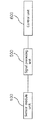
Fig. 1 is a block diagram showing a structure of a measurement system for tensile force of strand using guided waves according to an embodiment of the present invention
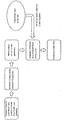
Fig. 2 is a block diagram showing a method and a procedure for measuring a tensile force of the spectrum diagnosis unit of Fig. 1
Fig. 3 is a perspective view showing the first embodiment of the sensor module unit of Fig. 1
Fig. 4 is a perspective view showing a sliding attached state where a sensor unit and magnetic unit slidingly attached and detached in the sensor module unit of Fig. 3
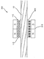
Fig. 5 is a perspective view showing a second embodiment of the sensor module unit of Fig. 1
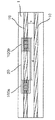
Fig.6 and Fig. 7 are perspective views showing a third embodiment of the sensor module unit of Fig. 1
Fig. 8 is a perspective view showing a fourth embodiment of the sensor module unit of Fig. 1
Fig. 9 is a drawing showing a state in which a sensor unit according to a pitch-catch method is installed on an object in a method of measuring a tensile force using a strand tensile force measuring system according to an embodiment of the present invention
Fig. 10 is a drawing illustrating a state in which a sensor unit according to a pulse-echo method installed on an object in a method of measuring a tensile force using a strand tensile force measuring system according to other embodiment of the present invention
Fig. 11 and Fig. 17 are drawings showing various target facilities in which the measurement system for tensile force of strand of Fig. 9 and Fig. 10 is installed
Fig. 18 is a photograph showing the test equipment of the sensor module unit shown in Fig. 5, which was experimentally tested by applying the pitch-catch method of Fig. 8
Fig. 19 is a drawing showing a state in which the sensor module unit of Fig. 18 is installed and thereby a method of oscillating various guided waves
Fig. 20 is a graph showing the time-varying amplitude signal and its time-frequency analysis of the guided waves propagated in the strand in Fig. 18
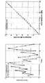
Fig. 21 is a graph showing frequency trajectories of the singularities with respect to unloading and loading conditions and various acting forces in Fig. 18
Fig. 22 and Fig. 23 are graphs comparing and analyzing the actual tensile force and the predicted tensile force in Fig. 17
According to a first aspect of the present invention, it attached to the object consisted with strand and guided wave having a dispersion in the object is oscillated, a sensor module unit for measuring a tensile force applied to the object by receiving the guided wave transmitted through the object, and a signal of the guided wave received from the object through the sensor module unit is measured, a signal processing unit for converting the measured signal into a spectrum in a frequency domain; and a control unit for analyzing a spectrum of the frequency domain converted by the above-mentioned signal processing unit and calculating a tensile force of the above-mentioned object, and the above-mentioned sensor module unit includes a sensor unit configured to surround the above-mentioned object, and a magnetic unit that provides a magnetic force to the sensor unit according to an electric current applied using an electromagnet. With all these, the present invention provides tensile force measurement system of strand using guided wave which distinguishes using magnetostriction principle of above-mentioned object.
Hereinafter, preferred embodiments of the present invention will be described in detail with reference to the accompanying drawings.
Referring to Fig. 1, a measurement system for a tensile force of a strand using a guided wave according to a first embodiment of the present invention (hereinafter referred to as a 'measurement system for a tensile force') is able to detect a tensile force loss or corrosion bond of strand by using a guided wave or an EMAT (electromagnetic acoustic transducer), it includes a sensor module unit (100), a signal processing unit (500), and a control unit (600).
First, the sensor module unit (100) is fixed to an object (10) made of a strand and oscillates a guided wave having a dispersion in the object (10), and a guided wave transmitted through the object (10) and then measures a tensile force applied to the object (10).
In this case, the sensor module unit (100) may be fixed to the object (10) at the time of initial installation of the structure before the object (10) is installed on the structure, or may be fixed to the object (10) exposed after completion of the structure.
In detail, referring to Fig. 3, the sensor module unit (100) includes a sensor unit (110) configured to surround the object (10) and a magnetic unit (120) providing a magnetic force to the sensor unit (110) according to an electric current applied using an electromagnet to use the magnetostriction principle of the object (10).
The sensor unit (110) includes a sensor bobbin (111) formed in a hollow cylindrical shape and inserted into the object (10) through the longitudinal direction and connected to the object (10) in a contact or non-contact manner, and a sensor coil (112) wound around the outer surface of the sensor bobbin (111) in the circumferential direction.
The sensor bobbin (111) is arranged on the outer circumferential surface in a plurality of locations along the longitudinal direction, a plurality of winding grooves (113) are formed in an annular shape along the circumferential direction so that the sensor coil (112) can be wound on each of the winding grooves 113.
The magnetic unit (120) has a hollow cylindrical shape and has a structure in which the sensor unit (110) can be inserted in a longitudinal direction.
In detail, the magnetic unit (120) includes a magnetic bobbin (121) formed of a hollow cylindrical shape and formed to surround the sensor unit (110) and made of an electromagnet, and a magnetic bobbin (121) wound around in the circumferential direction by a magnetic coil (122).
The magnetic bobbin (121) has the same length as the sensor bobbin (111) and the magnetic coil (122) is wound in an annular shape with the sensor coil (112) and the object (10) being coaxial.
Meanwhile, the magnetic unit (120) has a structure in which the sensor unit (110) is slidably detached along the inner circumferential side, thereby facilitating the maintenance of the sensor unit (110).
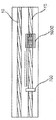
On the other hand, at this time, the detachment structure of the sensor unit (110) and the magnetic unit (120) is consist as the outer circumferential surface of the sensor bobbin (111) is slidably contacted with the inner circumferential surface of the magnetic bobbin (121), and the sensor unit (110) may be inserted into the inner circumferential surface of the magnetic unit (120) as shown in Fig. 4.
In here, the magnetic unit (120) may include a structure in which a stopper unit such as a latching groove is formed therein to limit the sliding movement of the sensor unit (110).
Meanwhile, although not shown, a known current supplying device for applying a high current to the sensor unit (110) including the electromagnet is connected to the sensor module unit (100), and a description thereof will be omitted.
The signal processing unit 500 measures a signal of the guided wave received from the object (10) through the sensor module unit (100) and converts the measured signal into a spectrum in a frequency domain.
The signal processing unit (500) includes a signal measuring unit for measuring a signal of the guided wave induced and received along the object (10) and a frequency converter for converting the signal received from the signal measuring unit into a spectrum of frequency domain.
The control unit (600) analyzes the spectrum of the frequency domain converted by the signal processing unit (500) and calculates the tensile force of the object (10). Also the control unit (600) analyzes a pattern appearing on the converted spectrum and calculates the tensile force applied to the object (10).
As shown in Fig. 2, the control unit (600) extract singularities after analyzes a frequency response characteristic with variation of tensile force (loading and unloading), analyzes a pattern of the singularities, sets a fitting curve, measures a tensile force and a detailed description of the method and procedure for measuring the tensile force of the control unit (600) will be described later.
According to the above description, the sensor module unit (100) according to the first embodiment is a magnetostrictive sensor using an electromagnet, and can be downsized in size, and a uniformed magnetic field can be applied because an electromagnet is used.
Referring to Fig. 5, a description will be made of a measurement system of a tensile force according to a second embodiment of the present invention.
Unlike Fig. 3, a magnetostrictive sensor using a permanent magnet, the measurement system of a tensile force according to the second embodiment includes a sensor module unit (200), a signal processing unit (500), and a control unit (600).
Here, the signal processing unit (500) and the control unit (600) are substantially the same as the configuration of FIG. 1, and therefore, the sensor module unit (200) will be described below.
The sensor module unit (200) is fixed to an object (10) made of a strand and oscillates a guided wave having a dispersion in the object (10) and receives the guided wave through measuring a tensile force applied to the object (10).
In here, the sensor module unit (200) uses the principle of magnetostriction of the object (10) by including a sensor unit (110) configured to surround the object (10) and a magnetic unit (210) providing a magnetic force to the sensor unit (110) using a permanent magnet.
In detail, the sensor unit (110) includes a sensor bobbin (111) formed in a hollow cylindrical shape and inserted into the object (10) along the longitudinal direction, a sensor coil (112) wound on the outer circumferential surface of the sensor bobbin (111) along a circumferential direction, and the plurality of sensor bobbins (111) are arranged on the outer circumferential surface so as to be spaced apart from each other in the longitudinal direction, and a plurality of winding grooves (113) through which the sensor coil (112) is wound are formed.
The magnetic unit (210) includes a first magnet unit (211) formed at one end of the sensor unit (110) and made of a permanent magnet, a second magnet unit (212) disposed at the other end portion of the sensor unit (110) and made of a permanent magnet, a yoke unit (213) and a buffer unit.
Here, the first magnet unit (211) and the second magnet unit (212) are arranged in such a manner that a plurality of quadrangular permanent magnets is annularly spaced from each other around the object (10) in the circumferential direction.
The yoke unit (213) is located on the outer side of the first magnet unit (211) and the second magnet unit (212) and both lower ends thereof are connected to the first magnet unit (211) and the second magnet unit (212), respectively.
Meanwhile in the drawing, each three of the first magnet unit (211) and the second magnet unit (212) are connected to the object (10) at a spacing angle of 120 degrees; therefore, the yoke unit (213) is also composed of three yokes as shown in the example but the present invention is not limited thereto.
The buffer unit is located between object (10) and the first magnetic unit (210) and includes a first buffer unit (214) between a first magnetic unit (211) and the object (10) and the second buffer unit (215) between the second magnetic unit (212) and the object (10).
As described above, the sensor module unit (200) according to the second embodiment has the permanent magnets arranged at one end and the other end of the sensor unit (110), respectively, and is arranged in a radial symmetrical structure with respect to the object (10) and the yoke (213) is formed so as a uniform magnetic field is applied to the yoke (213). The sensor size can be increased according to the volume of the permanent magnet, and the configuration of the oscillating and measuring instrument is simple compared to the case of using the electromagnet of Fig. 3, and the transmission / reception sensitivity can also be improved.
Hereinafter, a measurement system of a tensile force according to a third embodiment of the present invention will be described with reference to Fig. 6 and Fig. 7.
As refer to Fig. 3, the sensor unit (110) of the sensor module unit (300) is same as a measurement system of a tensile force according to a third embodiment compared to Fig. 3 except that a permanent magnet other than the electromagnet is applied to the magnetic unit (310).
In this regard, the magnetic unit (310) is formed of a hollow cylindrical permanent magnet, and is configured to surround the outside of the sensor unit (110).
At this time, the sensor unit (110) and the magnetic unit (310) are slidably attached to and detached from each other as shown in Fig. 4, and they can be slidingly attached to each other as shown in Fig. 7.
In the above case, the sensor module unit (300) is a magnetostrictive sensor using a cylindrical permanent magnet of a ring structure and the yoke is removed and the object (10) (strand) serves as a yoke. Compared to a rectangular permanent magnet structure in Fig. 5., it is easy to configure and can be miniaturized in size, and its oscillation / measurement device configuration has a merit in comparison with an electromagnet.
Hereinafter, a measurement system of a tensile force according to a fourth embodiment of the present invention will be described with reference to Fig. 8.
Referring to the drawing, the measurement system of a tensile force includes a sensor module unit (400), a described signal processing unit (500), and a control unit (600), which are applied magnetostrictive patches. The wave is generated by attaching the thin patch unit (410) to the outer surface of object (10) which is a strand and transmitting the magnetostrictive of the patch to the object (10).
The sensor module unit (400) in detail includes a patch unit (410) configured to surround the object (10) and a sensor unit (110) configured to surround the patch unit (410) and a magnetic unit (310) providing a magnetic force to the sensor unit (110).
The sensor unit (110) includes a sensor bobbin (111) formed in a hollow cylindrical shape and inserted into the object (10) to penetrate in the longitudinal direction, a sensor coil (112) wound around the outer circumferential surface of the sensor bobbin (111) in the circumferential direction and the sensor bobbin (111) is formed with the winding grooves (113) described above.
The magnetic unit (310) is formed of an electromagnet, has a hollow cylindrical shape and it is inserted into the sensor unit (110) to penetrate in the longitudinal direction and has a hollow cylindrical shape and is configured to surround the sensor unit (110). It includes the magnetic bobbin (121) made of an electromagnet and a magnetic coil (122) wound around the circumference of the magnetic bobbin (121) in the circumferential direction.
The magnetic unit (310) can be a permanent magnet and has a hollow cylindrical shape to the sensor unit (110) to penetrate and inserted into and the sensor unit (110) may be detachably attached along the inner circumferential surface in a sliding manner.
In the meantime, although the magnetic unit (310) in the drawing shows a case where a permanent magnet is applied, it is needless to say that other magnetic can be used.
The patch unit (410) uses Magnetostrctive Patch and is formed of a material having a higher magnetostriction than the object (10) and may be formed of nickel or an iron-cobalt alloy material but can use other materials as long as the above objects can be achieved.
Hereinafter, a method of monitoring the tensile force by using the above-described measurement system of a tensile force will be described.
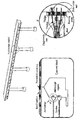
Referring to Fig. 9, as look into a monitoring method of monitoring a tensile force according to the first embodiment, first, in the case of the first embodiment by pitch-catch method, a pair of sensor module units (100a, 100b) are spaced apart from the object (10) according to the set distance to able to send and receive.
At this time, when the sensor module unit is installed, as securing the distance (w) between the strand in the fixture, the distance (D) between the transmitting and receiving sensor sub-modules is fixed and the installation is easy when the object (10) is exposed.
At this time, it is preferable to insert the filler (20) between the sensor module units after fixing the pair of sensor module units to the object (10).
This is to exclude the propagation features change due to grouting in the wave propagation section in the case of the pitch-catch method.
Here, the filler can be charged by applying oil, but is not limited thereto.
According to this, the pair of sensor module unit is fixedly fixed to the object (10) according to the set distance, and the pair of sensor module units and the filler (20) have an integrated structure.
Then, the guided wave is oscillated and received in the pitch-catch method on the object (10) through the sensor module unit, and the signal induced by the object (10) is transmitted to the signal processing unit (500) and converts the measured signal into a spectrum in the frequency domain.
Thereafter, the control unit (600) analyzes the spectrum of the frequency domain converted by the signal processing unit (500) to calculate the tensile force of the object (10).
According to the above description, in order to exclude a change in the propagation features due to grouting in the wave propagation section, the pitch-catch method may be configured and an extrapolated EMAT (Electromagnetic acoustic transducer) is inserted between the transmitter unit (Tx) and the sensor module unit of the receiver (Rx) for the embedded or exposed strand of oil filler (20). Also it is integrally structured to fix the distance between the transmitter (Tx) and the receiver (Rx).
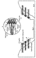
Referring to Fig. 10, as look into a monitoring method of a tensile force according to the second embodiment, a pulse echo method is used in the second embodiment, and a single sensor module unit (100c) capable of both transmitting and receiving to the object (10) and a reflector (700) to be spaced apart from the sensor module unit (100c) by a predetermined distance are fixed.
Here, the reflector (700) can shorten the return time of the guided waves.
Then, when the guided wave is generated in the object (10) by the sensor module unit through the sensor module unit and the reflector (700) in a pulse echo method, the guided wave reflected from the reflector (700) is received a signal derived by the object (10) is measured through the signal processor (500), and the measured signal is converted into a spectrum in a frequency domain.
Here, the signal processor (500) may perform frequency conversion using at least one of a Fourier transform (FT), a Fast Fourier transform (FFT), and a Short-Time Fourier Transform (STFT); however, it is needless to say that conversion into other method is possible as long as the above object can be achieved.
When the signal is converted by the signal processing unit (500), the control unit (600) analyzes the spectrum of the frequency domain converted by the signal processing unit (500) and calculates the tensile force of the object (10).
Here, the control unit (600) analyzes a pattern of a singularities appearing on the transformed spectrum, and calculates a tensile force applied to the object (10).
On the other hand, the object (10) may be apply to a supporting cable of a bridge including a suspension bridge, a cable-stayed bridge, a rahmen bridge, a complexed bridge, or a hanger cable or load cable for supporting wire rope or a slope reinforcement or a cable or tendons in concrete structures where force acts.
On this, referring to Fig. 11 or Fig. 17, various embodiments of an object to which the measurement system of tensile force is applied and a structure thereof will be described.
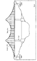
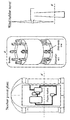
First, referring to Fig. 11 and Fig. 12, the measuring system for the tensile force may be applied to a suspension bridge of Fig. 11, and the detailed fixing position may be a main cable fixing hole or a hanger cable as shown in Fig. 12. It can be installed at the time of installation or after completion of an initial suspension bridge when the cable in the fixing room can be accessed. Also it is possible to estimate the tensile force of the Pitch-catch / Pulse-echo method and corrosion defect of pulse-echo method diagnosis is possible.
Fig. 13 is an example of a hanger cable of a suspension bridge, which can be installed directly on an exposed cable and in this case, the sensor module is designed to be waterproof and abrasion-resistant. Similarly, an estimation for a tensile force of pitch-catch/pulse-echo method and a corrosion defect diagnosis of pulse-echo method is all possible.
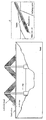
Fig. 14 and Fig. 15 are the case where it is applied to respectively a cable-stayed bridge and a rahmen bridge. The cable fixture can be accessed, so that it can be installed on the exposed strand of the insert / wedge in the fixture, and an estimation for a tensile force of pitch-catch/pulse-echo method and corrosion defect diagnosis of pulse-echo method is all possible.
Fig. 16 is a case where applied to slope reinforcing bar, which is accessible from a slope reinforced outer wall, and which can be installed on an exposed cable after insertion of an anchor cap or after removal of an anchor protection cap, and an estimation for a tensile force of pitch-catch/pulse-echo method and corrosion defect diagnosis of pulse-echo method is possible.
Fig. 17 shows an example applied to a power plant such as a large building or a nuclear dome / wind tower, which is applicable to all PSC structures subjected to a force, and an estimation for a tensile force of pitch-catch/pulse-echo method and corrosion defect diagnosis of pulse-echo method is possible.
Hereinafter, a description will be given of a test procedure and results of a measurement system of the tensile force using the guided wave.
The main task of this test is, performing loading and unloading the sensor module unit so that a certain force acts on the object and tensile force can be exerted and measure the signal accordingly and the process is initiate unloading/ loading the load, extracts featured curves including the trajectory at the singularities and sets and measures fittings for curves / functions on the extracted featured curves, so that the tensile force can be measured and predicted.
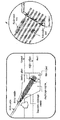
First, Fig. 18 is a photograph showing a test equipment for testing and installing the above-described sensor module unit on a test object by applying a pitch-catch method and calculates the basic parameter values for the feature of dispersion characteristics such as the time, distance, velocity, and average velocity of the oscillated guided waves.
On the other hand, as shown in the drawing, the experimental condition is about 11.22 tons for a single strand, and 110 KN is allowed to be loaded and the load was loaded and unloaded with a load of 110 kN. The pulser / receiver was RPR-4000, the frequency was burst 3 cycle excitation (500 kHz), the output ratio was 40, receiving gain is set to 60dB, and the sensor module is set as equipment and test condition of solenoid coil transmitter and solenoid coil (PCS) receiver.
Thus, when the test equipment including the sensor module is set, a guided wave according to the pitch-catch method is generated and received.
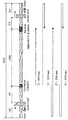
At this time, referring to Fig. 19, the signal strength is measured with respect to four kinds of signals; a time (t)1 at which a guided wave oscillated from the transmitter (Tx) reaches a direct signal to the receiver (Rx) is started, a time (t2) at which the edge reflected at the first oscillation direction is reflected and returned to the receiver (Rx), a time (t3) at which the guided wave oscillated in the opposite direction at the same time as the signal at the time (t1) is initially reflected on the edge of the stand and returns to the receiving unit (Rx), at time (t4) when the signal of the time t3 continues to shoot at one end of the stand and return to the receiver (Rx).
At this time, the basic parameter values for the feature of dispersion characteristics such as the time, distance, speed, and average velocity of the guided wave are calculated.
In addition, when the test data and the time-varying amplitude signal data for the oscillation frequency of the guided wave are obtained, these data are converted into the frequency signal as shown in Fig. 20.
In here, Fig. 20 is a graph showing the time-varying amplitude signal and the time-frequency analysis of the guided wave propagating in the strand.
Fig. 21 is a graph showing the frequency trajectories of the singularities with respect to unloading and loading conditions and various acting forces, wherein for each graph, the first singularities (1st), the second singularities (2nd), and the third singularities (3rd) are stated and the frequency trends are shown.
When the frequency characteristics is obtained according to the above, the fitting curve is set to measure and predict the tensile force like Fig. 22, and as a result, it can be confirmed that the result is substantially similar to the actual tensile force as shown in Fig. 23.
Therefore, the present invention for monitoring the tensile force of cable or tendon using the feature of dispersion characteristics of guided wave as described above is a method of monitoring and evaluating tensile force using a tensile force value actually applied to a strand to be tested and a pitch-catch method values were close to each other.
<Description of Reference Numerals>
100,200,300,400: Sensor Module Unit 110: Sensor Unit
111: Sensor bobbin 112: Sensor Coil
113: Winding Groove 120,210,310: Magnetic Unit
121: Magnetic Bobbin 122: Magnetic Coil
211: First Magnet Unit 212: Second Magnet Unit
213: Yoke Unit 214: First Buffer Unit
215: Second Buffer Unit 410: Patch Unit
500: Signal Processing Unit 600: Control Unit
700: Reflector
While the present invention has been described with reference to exemplary embodiments, it is to be understood that the invention is not limited to the disclosed exemplary embodiments, but, on the contrary, is intended to cover various modifications and equivalent arrangements included within the spirit and scope of the appended claims. Accordingly, the true scope for the technical prevention of the present invention should be determined by the technical idea of the appended scope of patent claims.
Claims (35)
- A guided wave having a dispersion is oscillated on the object made of a strand and a sensor module unit for measuring a tensile force applied to the object by receiving a guided wave transmitted through the above-mentioned object,A signal of the guided wave received from the above object is measured through the sensor module unit, and a signal processing unit converting the measured signal into a spectrum in a frequency domain; andincludes a control unit for analyzing a spectrum of the frequency domain converted by the signal processing unit and calculating a tensile force of the object,The sensor module unit is,a sensor unit configured to surround the object, and a tensile force measurement system of strand using a guided wave wherein a magnetostriction (MS) principle of the object is used including a magnetic part for providing a magnetic force to the sensor part according to an electric current applied using an electromagnet.
- According to claim 1,The sensor unit above is a sensor bobbin formed in a hollow cylindrical shape and inserted into the object in a longitudinal direction so as to penetrate the object, and is a measurement system for tensile force of strand using a guided wave with a sensor coil wound around an outer circumferential surface of the sensor bobbin in a circumferential direction.
- According to claim 2,The sensor bobbin is routed with a double lid from each other along the longitudinal direction on the outer circumferential surface and is a measurement system for tensile force using a guided wave wherein each is formed by an annular, long loop to enclose the sensor coil in a winding grooves.
- According to claim 2,The magnetic unit above is a measurement system for tensile force using a guided wave which is formed by a hollow cylindrical insertion of the sensor unit above into the inner direction of its length.
- According to claim 4,The magnetic unit is,a magnetic bobbin formed of a hollow cylindrical shape and formed to surround the sensor unit and made of an electromagnet, and is a tensile force measuring system of strand using a guided wave featured a magnetic coil wound on a circumferential surface of the magnetic bobbin along a circumferential direction of the magnetic bobbin.
- According to claim 4,The magnetic unit is,a measurement system for a tensile force of a strand using a guided wave wherein the sensor unit is formed to be detachably attached to the inner circumferential side surface in a sliding manner.
- According to claim 1,Above signal processing unit is,a signal measuring unit for measuring a signal of the received guided wave which is induced by above object, anda measurement system for a tensile force of a strand using a guided wave including a frequency converter for converting a signal received from the signal measuring unit into a spectrum of a frequency domain.
- A guided wave having a dispersion is oscillated on the object made of a strand and a sensor module unit for measuring a tensile force applied to the object by receiving a guided wave transmitted through the above-mentioned object,A signal of the guided wave received from the above object is measured through the sensor module unit, and a signal processing unit converting the measured signal into a spectrum in a frequency domain; andincludes a control unit for analyzing a spectrum of the frequency domain converted by the signal processing unit and calculating a tensile force of the object,The sensor module unit is,a sensor unit configured to surround the object, anda measurement system for the tensile force of a strand using a guided wave wherein the magnetostrictive principle of the object is used including the magnetic unit for providing a magnetic force to the above sensor using a permanent magnet.
- According to claim 8,The sensor unit above isa sensor bobbin formed in a hollow cylindrical shape and inserted into the object in a longitudinal direction so as to penetrate the object, andis a measurement system for tensile force of strand using a guided wave with a sensor coil wound around an outer circumferential surface of the sensor bobbin in a circumferential direction.
- According to claim 9,The sensor bobbin isa measurement system for tensile force of strand using guided waves which is distinguished by a plurality of winding grooves are formed on the outer circumferential surface so as to be spaced apart from each other along the longitudinal direction and each of the plurality of winding grooves is formed in an annular shape along the circumferential direction so as to surround the sensor coils.
- According to claim 8,The magnetic unit is,a first magnet unit located at one end of the above sensor unit and made of a permanent magnet,a second magnet unit located at the other end of the sensor unit and made of a permanent magnet, anda measurement system for a tensile force of a strand using a guided wave wherein includes yoke unit having both ends connected to the above first magnet part and the above second magnet part, respectively.
- According to claim 11,Wherein the first magnet unit and the second magnet unit each is,a measurement system for a tensile force of a strand using a guided wave wherein a plurality of quadrangular permanent magnets are arranged annularly spaced from each other along the circumferential direction of the object.
- According to claim 11,The magnetic unit is,A first buffer unit interposed between the first magnet unit and the object, anda measurement system for a tensile force of a strand using a guided wave wherein a second buffer unit interposed between the second magnet unit and the object.
- According to claim 8,The magnetic unit is,a measurement system for a tensile force of a strand using a guided wave wherein the sensor unit is inserted into the sensor unit through a cylindrical permanent magnet so as to penetrate the sensor unit along the longitudinal direction to the inside.
- According to claim 14,The magnetic unit is,a measurement system for a tensile force of a strand using a guided wave wherein the sensor unit is formed to be detachably attached to the inner circumferential side surface in a sliding manner.
- According to claim 8,Above signal processing unit is,a signal measuring unit for measuring a signal of the received guided wave which is induced by above object, anda measurement system for a tensile force of a strand using a guided wave including a frequency converter for converting a signal received from the signal measuring unit into a spectrum of a frequency domain.
- A guided wave having a dispersion is oscillated on the object made of a strand and a sensor module unit for measuring a tensile force applied to the object by receiving a guided wave transmitted through the above-mentioned object,A signal of the guided wave received from the above object is measured through the sensor module unit, and a signal processing unit converting the measured signal into a spectrum in a frequency domain; andincludes a control unit for analyzing a spectrum of the frequency domain converted by the signal processing unit and calculating a tensile force of the object,The sensor module unit is,a patch unit configured to surround the object,a sensor unit formed to surround the patch unit, anda measurement system for a tensile force of a strand using a guided wave wherein the magnetostrictive principle of the patch unit is used including a magnetic unit for providing a magnetic force to the sensor part.
- According to claim 17,The sensor unit above isa sensor bobbin formed in a hollow cylindrical shape and inserted into the object in a longitudinal direction so as to penetrate the object, andis a measurement system for tensile force of strand using a guided wave with a sensor coil wound around an outer circumferential surface of the sensor bobbin in a circumferential direction.
- According to claim 18,The sensor bobbin isa measurement system for tensile force of strand using guided waves which is distinguished by a plurality of winding grooves are formed on the outer circumferential surface so as to be spaced apart from each other along the longitudinal direction and each of the plurality of winding grooves is formed in an annular shape along the circumferential direction so as to surround the sensor coils.
- According to claim 18,The magnetic unit is,a measurement system for a tensile force of a strand using a guided wave wherein the electromagnet is formed of an electromagnet and has a hollow cylindrical shape, and is inserted into the sensor unit through the sensor unit in the longitudinal direction.
- According to claim 20,The magnetic unit is,a magnetic bobbin formed of a hollow cylindrical shape and formed to surround the sensor unit and made of an electromagnet, anda measurement system for a tensile force of a strand using a guided wave wherein magnetic coil wound on a circumferential surface of the magnetic bobbin along a circumferential direction of the magnetic bobbin.
- According to claim 18,The magnetic unit is,a measurement system for a tensile force of a strand using a guided wave wherein the sensor unit is formed of a permanent magnet and has a hollow cylindrical shape so that the sensor unit is inserted into the sensor unit in a longitudinal direction thereof.
- According to claim 22,The magnetic unit is,a measurement system for a tensile force of a strand using a guided wave wherein the sensor unit is formed to be detachably attached to the inner circumferential side surface in a sliding manner.
- According to claim 17,Above-mentioned patch unit isis a measurement system for a tensile force of a strand using a guided wave wherein the object is formed of a material having higher magnetostriction than the object.
- According to claim 24,Above-mentioned patch unit isis a measurement system for a tensile force of a strand using a guided wave wherein nickel or iron-cobalt formed in the alloy material.
- According to claim 17,Above signal processing unit is,a signal measuring unit for measuring a signal of the received guided wave which is induced by above object, anda measurement system for a tensile force of a strand using a guided wave including a frequency converter for converting a signal received from the signal measuring unit into a spectrum of a frequency domain.
- A monitoring method for a tensile force of a strand using a guided wave using a measuring system for a tensile force using a guided wave according to any one of claims 1 to 26,a step of fixing a pair of the sensor module units so as to be able to transmit and receive the object to be spaced apart from each other according to the set distance,a step where generating and receiving a guided wave by a pitch-catch method on the object through above sensor module unit, measuring a signal induced by the object through the signal processing unit, and converting the measured above signal in a frequency domain into a spectrum, anda monitoring method for the tensile force of a strand using a guided wave wherein analyzing the spectrum of the frequency domain converted by the signal processing unit above through the above control unit calculate a tensile force of the object above.
- In a claim 27,a monitoring method for a tensile force of a strand using a guided wave wherein further comprising the step of inserting a filler between the sensor module units after fixing the pair of sensor module units to the object.
- In a claim 28,above filler is,a monitoring method for the tensile force of a strand using a guided wave wherein applying oil.
- In a claim 28,The sensor module unit is,a monitoring method for a tensile force of strand using a guided wave wherein a pair of the sensor module units and the filler are integrally formed in a fixed manner and the pair of sensor module units being fixed to the object according to the set spacing distance.
- In a method of monitoring a tensile force using a guided wave using a measuring system of tensile force using the guided wave according to any one of claim 1 or 26,A stage where attaching each of the above sensor module unit capable of transmitting and receiving the above object, and the reflector being spaced apart from the above sensor module unit by a predetermined distance.A stage of pulse echo method for generating and receiving a guided wave on the object through the above sensor module unit and the above reflector to measure a signal induced by the above object through the signal processing unit, convert a measure above signal to a spectrum of frequency domain, anda monitoring method for the tensile force of a strand using a guided wave wherein analyzing the spectrum of the frequency domain converted by the signal processing unit above through the above control unit calculate a tensile force of the object above.
- According to any one of claim 27 or 31,Above object is,a measurement system for a tensile force of strand using a guided wave wherein comprises a cable or tendon in a supporting cable or hanger cable or load-supporting wire rope or slope reinforcement of a bridge including a suspension bridge, a cable-stayed bridge, a rahmen bridge and complex bridge.
- In a claim 32,The sensor module unit is,a measurement system for a tensile force of a strand using a guided wave wherein the object is fixed to the structure at the time of initial installation of the object before the object is installed on the structure or is fixed to the object exposed after completion of the structure.
- According to any one of claim 27 or 31,Above signal processing unit is,a measurement system for tensile force of a strand using a guided wave wherein the frequency transformation is performed using at least one of a Fourier Transform (FT), a Fast Fourier Transform (FFT), and a Short-Time Fourier Transform (STFT).
- In a claim 34,above control unit is,a measurement system for a tensile force of strand using a guided wave wherein analyzing the pattern of singularities on the converted spectrum and calculating the tensile force on the above object.
Applications Claiming Priority (4)
| Application Number | Priority Date | Filing Date | Title |
|---|---|---|---|
| KR20170133258 | 2017-10-13 | ||
| KR10-2017-0133258 | 2017-10-13 | ||
| KR10-2017-0173794 | 2017-12-18 | ||
| KR1020170173794A KR102009693B1 (en) | 2017-10-13 | 2017-12-18 | Measurement system for tensile force of strand using guided wave and monitoring method of tensile force using thereof |
Publications (1)
| Publication Number | Publication Date |
|---|---|
| WO2019074174A1 true WO2019074174A1 (en) | 2019-04-18 |
Family
ID=66100799
Family Applications (1)
| Application Number | Title | Priority Date | Filing Date |
|---|---|---|---|
| PCT/KR2018/003458 Ceased WO2019074174A1 (en) | 2017-10-13 | 2018-03-23 | Measurement system for tensile force of strand using guided wave and monitoring method of tensile force using thereof |
Country Status (1)
| Country | Link |
|---|---|
| WO (1) | WO2019074174A1 (en) |
Citations (5)
| Publication number | Priority date | Publication date | Assignee | Title |
|---|---|---|---|---|
| US5821430A (en) * | 1997-02-28 | 1998-10-13 | Southwest Research Institute | Method and apparatus for conducting in-situ nondestructive tensile load measurements in cables and ropes |
| US6815948B1 (en) * | 2003-09-30 | 2004-11-09 | The Tokyo Electric Power Company, Inc. | Method of detecting tension wire break in concrete pole |
| US6868730B2 (en) * | 2002-11-08 | 2005-03-22 | Seoul National University Industry Foundation | Methods and apparatus for measuring flexural wave and/or flexural vibration using a magnetostrictive sensor |
| US20100052670A1 (en) * | 2008-08-29 | 2010-03-04 | Southwest Research Institute | Magnetostrictive Sensor Probe for Guided-Wave Inspection and Monitoring of Wire Ropes/Cables and Anchor Rods |
| CN102841132A (en) * | 2012-09-05 | 2012-12-26 | 北京工业大学 | Flexible magnetostriction and eddy integrated sensor for detecting defects of high-voltage transmission line |
-
2018
- 2018-03-23 WO PCT/KR2018/003458 patent/WO2019074174A1/en not_active Ceased
Patent Citations (5)
| Publication number | Priority date | Publication date | Assignee | Title |
|---|---|---|---|---|
| US5821430A (en) * | 1997-02-28 | 1998-10-13 | Southwest Research Institute | Method and apparatus for conducting in-situ nondestructive tensile load measurements in cables and ropes |
| US6868730B2 (en) * | 2002-11-08 | 2005-03-22 | Seoul National University Industry Foundation | Methods and apparatus for measuring flexural wave and/or flexural vibration using a magnetostrictive sensor |
| US6815948B1 (en) * | 2003-09-30 | 2004-11-09 | The Tokyo Electric Power Company, Inc. | Method of detecting tension wire break in concrete pole |
| US20100052670A1 (en) * | 2008-08-29 | 2010-03-04 | Southwest Research Institute | Magnetostrictive Sensor Probe for Guided-Wave Inspection and Monitoring of Wire Ropes/Cables and Anchor Rods |
| CN102841132A (en) * | 2012-09-05 | 2012-12-26 | 北京工业大学 | Flexible magnetostriction and eddy integrated sensor for detecting defects of high-voltage transmission line |
Similar Documents
| Publication | Publication Date | Title |
|---|---|---|
| US5821430A (en) | Method and apparatus for conducting in-situ nondestructive tensile load measurements in cables and ropes | |
| KR102225514B1 (en) | Smart anchor head with integrated tensile measuremet sensor and strand tensile force measurement and diagnosis method using thereof | |
| US6880403B1 (en) | Structure inspection device | |
| EP2427758B1 (en) | Non-contact acoustic signal propagation property evaluation of synthetic fiber rope | |
| CN106092383A (en) | Magnetic bullet cable force measurement method and restructural magnetic-elastic stress sensor thereof | |
| JPH09508959A (en) | Electromagnetic acoustic transducer for bolt tension and load measurement | |
| CN109406631B (en) | Parallel steel wire sling detection device and method | |
| KR101552793B1 (en) | PSC Anchorage For Monitoring A Status Change of PS Steel Member and PSC Girder Using the Same | |
| Gao et al. | Tension monitoring and defect detection by magnetostrictive longitudinal guided wave for fine wire rope | |
| Xu et al. | Effect of tensile force on magnetostrictive sensors for generating and receiving longitudinal mode guided waves in steel wires | |
| CN111060228A (en) | Method for detecting prestress of in-service anchor cable | |
| WO2019074174A1 (en) | Measurement system for tensile force of strand using guided wave and monitoring method of tensile force using thereof | |
| CN108051502B (en) | A detection method for cable fatigue damage | |
| CN207366489U (en) | It is a kind of to be used to monitor the elastic piezoelectric ceramics system of anchoring | |
| Zhang et al. | A longitudinal mode guided wave transducer with the ring permanent biased magnet based on magnetostrictive effect for large diameter bridge cables | |
| CN107894443A (en) | It is a kind of to be used to monitor anchoring elastic piezoelectric ceramics system and monitoring method | |
| CN104034803B (en) | The sensing device that main passive waveguide monitoring bridge draws hoist cable to damage and monitoring method thereof | |
| KR102009693B1 (en) | Measurement system for tensile force of strand using guided wave and monitoring method of tensile force using thereof | |
| WO2020004724A1 (en) | The stationary type apparatus for measuring tensile force of strands using guided wave | |
| CN112684001A (en) | Ultrasonic guided wave nondestructive detection device for power transmission conductor and damage identification method | |
| WO1999053282A1 (en) | Method and apparatus for conducting in-situ nondestructive tensile load measurements in cables and ropes | |
| Bishop et al. | A rapid-acquisition electrical time-domain reflectometer for dynamic structure analysis | |
| Witoś et al. | NDE of mining ropes and conveyors using magnetic methods | |
| RU2737226C1 (en) | Electromagnetic-acoustic introscope for diagnostic inspection of casing strings and tubing of wells | |
| Johannes et al. | Application of the Acousto-Ultrasonics Technique to Bridge Cables in Their Anchorages |
Legal Events
| Date | Code | Title | Description |
|---|---|---|---|
| 121 | Ep: the epo has been informed by wipo that ep was designated in this application |
Ref document number: 18865642 Country of ref document: EP Kind code of ref document: A1 |
|
| NENP | Non-entry into the national phase |
Ref country code: DE |
|
| 122 | Ep: pct application non-entry in european phase |
Ref document number: 18865642 Country of ref document: EP Kind code of ref document: A1 |