WO2019057147A1 - Positioning connection device and building module device - Google Patents
Positioning connection device and building module device Download PDFInfo
- Publication number
- WO2019057147A1 WO2019057147A1 PCT/CN2018/106915 CN2018106915W WO2019057147A1 WO 2019057147 A1 WO2019057147 A1 WO 2019057147A1 CN 2018106915 W CN2018106915 W CN 2018106915W WO 2019057147 A1 WO2019057147 A1 WO 2019057147A1
- Authority
- WO
- WIPO (PCT)
- Prior art keywords
- positioning
- reference plate
- building module
- hole
- cone
- Prior art date
Links
Images


Classifications
-
- E—FIXED CONSTRUCTIONS
- E04—BUILDING
- E04B—GENERAL BUILDING CONSTRUCTIONS; WALLS, e.g. PARTITIONS; ROOFS; FLOORS; CEILINGS; INSULATION OR OTHER PROTECTION OF BUILDINGS
- E04B1/00—Constructions in general; Structures which are not restricted either to walls, e.g. partitions, or floors or ceilings or roofs
- E04B1/348—Structures composed of units comprising at least considerable parts of two sides of a room, e.g. box-like or cell-like units closed or in skeleton form
- E04B1/34815—Elements not integrated in a skeleton
- E04B1/3483—Elements not integrated in a skeleton the supporting structure consisting of metal
-
- E—FIXED CONSTRUCTIONS
- E04—BUILDING
- E04G—SCAFFOLDING; FORMS; SHUTTERING; BUILDING IMPLEMENTS OR AIDS, OR THEIR USE; HANDLING BUILDING MATERIALS ON THE SITE; REPAIRING, BREAKING-UP OR OTHER WORK ON EXISTING BUILDINGS
- E04G21/00—Preparing, conveying, or working-up building materials or building elements in situ; Other devices or measures for constructional work
- E04G21/14—Conveying or assembling building elements
- E04G21/16—Tools or apparatus
- E04G21/18—Adjusting tools; Templates
- E04G21/1841—Means for positioning building parts or elements
- E04G21/185—Means for positioning building parts or elements for anchoring elements or elements to be incorporated in the structure
-
- E—FIXED CONSTRUCTIONS
- E04—BUILDING
- E04B—GENERAL BUILDING CONSTRUCTIONS; WALLS, e.g. PARTITIONS; ROOFS; FLOORS; CEILINGS; INSULATION OR OTHER PROTECTION OF BUILDINGS
- E04B1/00—Constructions in general; Structures which are not restricted either to walls, e.g. partitions, or floors or ceilings or roofs
- E04B1/343—Structures characterised by movable, separable, or collapsible parts, e.g. for transport
-
- B—PERFORMING OPERATIONS; TRANSPORTING
- B65—CONVEYING; PACKING; STORING; HANDLING THIN OR FILAMENTARY MATERIAL
- B65D—CONTAINERS FOR STORAGE OR TRANSPORT OF ARTICLES OR MATERIALS, e.g. BAGS, BARRELS, BOTTLES, BOXES, CANS, CARTONS, CRATES, DRUMS, JARS, TANKS, HOPPERS, FORWARDING CONTAINERS; ACCESSORIES, CLOSURES, OR FITTINGS THEREFOR; PACKAGING ELEMENTS; PACKAGES
- B65D90/00—Component parts, details or accessories for large containers
- B65D90/0006—Coupling devices between containers, e.g. ISO-containers
-
- E—FIXED CONSTRUCTIONS
- E04—BUILDING
- E04B—GENERAL BUILDING CONSTRUCTIONS; WALLS, e.g. PARTITIONS; ROOFS; FLOORS; CEILINGS; INSULATION OR OTHER PROTECTION OF BUILDINGS
- E04B1/00—Constructions in general; Structures which are not restricted either to walls, e.g. partitions, or floors or ceilings or roofs
- E04B1/35—Extraordinary methods of construction, e.g. lift-slab, jack-block
-
- E—FIXED CONSTRUCTIONS
- E04—BUILDING
- E04B—GENERAL BUILDING CONSTRUCTIONS; WALLS, e.g. PARTITIONS; ROOFS; FLOORS; CEILINGS; INSULATION OR OTHER PROTECTION OF BUILDINGS
- E04B1/00—Constructions in general; Structures which are not restricted either to walls, e.g. partitions, or floors or ceilings or roofs
- E04B1/38—Connections for building structures in general
-
- E—FIXED CONSTRUCTIONS
- E04—BUILDING
- E04G—SCAFFOLDING; FORMS; SHUTTERING; BUILDING IMPLEMENTS OR AIDS, OR THEIR USE; HANDLING BUILDING MATERIALS ON THE SITE; REPAIRING, BREAKING-UP OR OTHER WORK ON EXISTING BUILDINGS
- E04G21/00—Preparing, conveying, or working-up building materials or building elements in situ; Other devices or measures for constructional work
- E04G21/14—Conveying or assembling building elements
- E04G21/16—Tools or apparatus
- E04G21/18—Adjusting tools; Templates
- E04G21/1841—Means for positioning building parts or elements
-
- E—FIXED CONSTRUCTIONS
- E04—BUILDING
- E04G—SCAFFOLDING; FORMS; SHUTTERING; BUILDING IMPLEMENTS OR AIDS, OR THEIR USE; HANDLING BUILDING MATERIALS ON THE SITE; REPAIRING, BREAKING-UP OR OTHER WORK ON EXISTING BUILDINGS
- E04G21/00—Preparing, conveying, or working-up building materials or building elements in situ; Other devices or measures for constructional work
- E04G21/24—Safety or protective measures preventing damage to building parts or finishing work during construction
- E04G21/26—Strutting means for wall parts; Supports or the like, e.g. for holding in position prefabricated walls
Definitions
- the present invention relates to the field of fabricated building steel structure construction technology, and more particularly to a positioning connection device and a building module device.
- the box module building is a type of fabricated steel structure. Because the building module can be completed by pre-installing in the factory and stacking on the project site, the box-type module building has the characteristics of high prefabrication, small workload on the construction site and short project duration. Among them, the manufacturing deviation of building modules and the stacking deviation at the project site have always been an important factor restricting the development of box-type modules. At present, because the interior decoration, external curtain wall and connection points of the construction project have high requirements on the installation accuracy, how to improve the positioning accuracy between the building modules in the construction project becomes an urgent problem to be solved in the box module construction. However, due to the technical limitations of the current building module positioning structure, the positioning structure in the prior art is difficult to achieve the positioning accuracy that meets the requirements of the construction project.
- the positioning structure between the building modules in the superimposed automatic positioning system of the modular building module and its connection method disclosed in CN104179254A can realize the reduction of the stacking code deviation of the building module during the stacking of the building module. The effect of positioning accuracy. As shown in FIG.
- the prior art building module positioning system includes four connecting members fixedly connected to the bottom of the superstructure module (at least one bidirectional positioning connector 1, at least one one-way positioning-one-way guiding connector 2 and At least one double bevel guide connector 3), and four square tubes fixedly attached to the top of the substructure module and disposed corresponding to the four connectors.
- the positioning and stacking of the upper and lower building modules is completed by the cooperation between the four connecting members at the bottom of the superstructure module and the four square tubes at the top of the sub-building module.
- the prior art building module positioning structure principle since the four connecting members and the four square tubes need to be fixedly connected to the building module, the positioning accuracy thereof is the same as the manufacturing precision of the building module. Therefore, the prior art building module positioning structure cannot avoid the influence of manufacturing deviation of the building module on the positioning accuracy of the building module.
- the current building modules are mainly composed of welded steel structures and have large specifications, which leads to the manufacturing precision of building modules becoming the main factor affecting the positioning accuracy of building modules. Therefore, in the prior art, if it is required to improve the positioning accuracy of the building module, it is necessary to pay a high price to improve the manufacturing precision of the building module.
- a building module device comprising a building module and a positioning connection device connected to the building module, the positioning connection device comprising :
- top reference plate being provided with a top positioning hole for connecting to a top of the building module
- the bottom reference plate is provided with a bottom positioning hole for connecting to a bottom of the building module
- top reference plate is positioned to a top predetermined position by the top positioning hole
- bottom reference plate is positioned to a bottom predetermined position by the bottom positioning hole, the top predetermined position and the bottom predetermined position being opposite to a predetermined position
- the reference points have the same horizontal coordinate position and are arranged vertically opposite each other.
- a building module device comprising a building module and a positioning connection device connected to the building module, the top reference plate being positioned to a top predetermined position by the top positioning hole, the bottom reference plate being positioned by the bottom positioning hole To a bottom predetermined position, the top predetermined position and the bottom predetermined position have the same horizontal coordinate position with respect to a predetermined reference point and are vertically oppositely arranged, and the building module device is positioned on the building module by the positioning connection device With high positioning accuracy and compact structure, it can meet the requirements of building modules for fast, simple and high-precision stacking and connection on the project site.
- the building modules are at least two, and the at least two building modules are fastened together by the top and bottom reference plates respectively positioned to the top predetermined position and the bottom predetermined position.
- the positioning accuracy is high, and the two building modules are connected accurately and compactly.
- a horizontal connector is further included to connect the two building modules in a horizontal direction.
- the two building modules are connected together in the horizontal direction, and the connection of the two building modules is stable.
- the building module is coupled to the ground by the bottom reference plate.
- the building module is fixed to the ground.
- the projection of the top reference plate at the predetermined position of the top and the bottom reference plate at a predetermined position of the bottom coincide in a height direction of the building module.
- the top reference plates are plural, and a top surface of the plurality of the top reference plates is coplanar to form a top reference plane;
- the bottom reference plate is a plurality of, and the bottom surfaces of the plurality of the bottom reference plates are coplanar to form a bottom reference plane.
- top surfaces of the top and bottom reference plates serve as the top and bottom reference planes of the building module.
- the building module is provided with a corner piece, the corner of the top reference plate has a notch for matching the corner piece to accommodate the corner piece; and/or
- the building module is provided with a bottom corner piece, the corner of the bottom reference plate having a notch for matching the bottom corner piece to accommodate the bottom corner piece.
- the building module is provided with a top corner piece, a top surface of the top reference plate is higher than a top surface of the top corner piece; and/or
- the building module is provided with a bottom corner piece, the bottom surface of the bottom reference plate being lower than the bottom surface of the bottom corner piece.
- top surfaces of the top and bottom reference plates serve as the top and bottom reference planes of the building module.
- the building module is provided with a top corner piece, a top surface of the top reference plate is higher than a top surface of the top corner piece, and the top corner piece is provided with a top corner piece spacer, so that the a top surface of the top corner spacer is coplanar with a top surface of the top reference panel; and/or
- the building module is provided with a bottom corner piece, a bottom surface of the bottom reference plate is lower than a bottom surface of the bottom corner piece, and a bottom corner piece is disposed at the bottom corner piece, so that the bottom corner piece
- the bottom surface of the gasket is coplanar with the bottom surface of the bottom reference plate.
- top corner spacer and the bottom corner spacer by adding the top corner spacer and the bottom corner spacer and ensuring that the top surface of the top corner spacer is coplanar with the top surface of the top reference plate, the bottom surface of the bottom corner spacer and the bottom reference plate The bottom surface is coplanar such that the top corner piece and the bottom corner piece are involved in the transfer of longitudinal loads.
- the invention also provides a positioning and connecting device for a building module, the positioning and connecting device comprising:
- top reference plate being provided with a top positioning hole for connecting to a top of the building module
- the bottom reference plate is provided with a bottom positioning hole for connecting to a bottom of the building module
- top reference plate is positioned to a top predetermined position by the top positioning hole
- bottom reference plate is positioned to a bottom predetermined position by the bottom positioning hole, the top predetermined position and the bottom predetermined position being opposite to a predetermined position
- the reference points have the same horizontal coordinate position and are arranged vertically opposite each other.
- the top reference plate is positioned to a top predetermined position by the top positioning hole
- the bottom reference plate is positioned to a bottom predetermined position by the bottom positioning hole
- the top predetermined position and the The bottom predetermined positions have the same horizontal coordinate position with respect to the predetermined reference point and are vertically opposed to each other.
- the positioning accuracy is high, the operation is simple, and the building module is compact. It can be used to reduce the influence of manufacturing deviation and stacking error on the positioning accuracy of the building module and to meet the fast, simple and high-precision stacking and connection of the building module at the project site.
- the top reference plate is a plurality, each of the top reference plates is provided with a positioning cone, and the top positioning hole of each of the top reference plates comprises a positioning cone disposed on a top of the positioning cone a hole, and a top positioning aperture disposed in the top reference plate, the positioning cone for extending through the bottom reference plate of the other of the positioning connectors.
- each of the top reference plates comprises a top positioning large hole
- the positioning cone is detachably fixed to the top positioning large hole, and a central axis of the positioning cone and a center line of the top positioning large hole coincide.
- the bottom reference plate is a plurality, and the bottom positioning holes of each of the bottom reference plates comprise a bottom positioning large hole and a bottom positioning small hole.
- a plurality of said bottom reference plates comprise:
- At least one first bottom reference plate, the bottom positioning large hole of the first bottom reference plate is used for clearance with the positioning cone of another positioning connection device or the tooling cone disposed on the tooling table, and the tolerance is Between ⁇ 0.5mm and ⁇ 1mm;
- At least one second bottom reference plate the bottom positioning large hole of the second bottom reference plate is a waist hole, and the waist hole is used for the positioning cone with another positioning connection device or at the tooling station
- the bottom hole of the first bottom reference plate is positioned, the waist hole of the second bottom reference plate is matched with the positioning cone or the tooling cone, and the matching tolerance is between ⁇ 0.5 mm and ⁇ 1 mm, thereby achieving the bottom reference. Precise positioning of the board and precise connection between the bottom reference plate and the top reference plate.
- the plurality of bottom reference plates further comprise: a third bottom reference plate, the bottom positioning large hole of the third bottom reference plate is used for the positioning cone or the tooling of the other positioning connection device
- the diameter of the bottom positioning large hole of the third bottom reference plate is larger than the diameter of the bottom positioning large hole of the first bottom reference plate, there is more active space for the building module having manufacturing deviation when performing stacking positioning. In order to position each of the bottom reference plates to a predetermined position at the bottom to ensure positioning accuracy.
- the bottom reference plate further includes a bottom connection hole
- the top reference plate further includes a top connection hole
- the bottom attachment hole is for a fastener to pass through to connect the bottom reference plate to the top reference plate of another of the positioning connection devices;
- the top attachment hole is for a fastener to pass through to connect the top reference plate to the bottom reference plate of another of the positioning connectors.
- the bottom reference plate is joined to the top reference plate by passing the fastener through the bottom connection hole and the bottom connection hole.
- FIG. 1 is a schematic structural view of a conventional building module having four connectors
- Figure 2 is a partial perspective cross-sectional view of a building module device in accordance with the present invention.
- Figure 3 is a front elevational view of a building module assembly in accordance with the present invention.
- Figure 4 is an exploded perspective view of a building module device in accordance with the present invention.
- Figure 5 is a top perspective view of a top reference plate of a positioning and connecting device in accordance with the present invention.
- FIG. 6 is a bottom perspective view of the top reference plate of the positioning and connecting device in accordance with the present invention.
- Figure 7 is a perspective view of a positioning cone of a positioning and connecting device according to the present invention.
- Figure 8 is a perspective view of a first bottom reference plate of a positioning and connecting device in accordance with the present invention.
- Figure 9 is a perspective view of a second bottom reference plate of the positioning and connecting device according to the present invention.
- Figure 10 is a perspective view of a third bottom reference plate of the positioning and connecting device according to the present invention.
- Figure 11 is a perspective view of a spacer of a positioning and connecting device in accordance with the present invention.
- Figure 12 is a perspective view of a position limiting member of the positioning and connecting device according to the present invention.
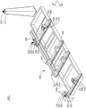
- Figure 13 is a perspective view of a positioning system in accordance with the present invention, wherein a bottom reference member is placed on the tooling table;
- Figure 14 is a partial schematic view of a portion A of Figure 13;
- Figure 15 is a perspective view of a positioning system in accordance with the present invention in which a building module and a top reference member are placed on a tooling station.
- bidirectional positioning connector 2 one-way positioning - one-way guiding connector
- top reference plate 111/111a/111b positioning cone
- positioning cone positioning hole 113 top positioning small hole
- the first bottom positioning large hole 132 the first bottom positioning small hole
- first bottom connection hole 140 second bottom reference plate
- second bottom connection hole 150 third bottom reference plate
- Main body 176 Bending structure
- top corner washer 106 bottom corner washer
- 110a third building module top reference plate
- 110b third building module top reference plate
- First building module 220 second building module
- Positioning System 310 Laser Positioning Instrument
- Gaotai 320 Tooling station
- Support base 331 Tooling cone
- rail 341 first rail
- locating pin 352 locating pin base
- Limiting plate 354 Limiting plate base
- the present invention provides a building modular device.
- the building modular device includes a positioning connection device 100 and a building module 200.
- the building module 200 can be a container or a building or product of other construction.
- the positioning connection device 100 can be used to connect two building modules stacked on top of each other, and can also be used to connect two building modules, such as two superstructure modules and two sub-building modules, and can also be used to connect building modules to ground.
- the positioning connection device 100 includes a top reference plate 110 and a bottom reference plate 120.
- the top reference plate 110 is for connection to the top of the building module 200 (refer to FIG. 15), and the bottom reference plate 120 is for connection to the bottom of the building module 200.
- the illustrated embodiment only shows a bottom corner portion of the building module 200, it can be understood with reference to FIGS. 13 and 15 that the top reference plates 110 are respectively disposed at the four top corner portions of the building module 200, the bottom reference The plates 120 are respectively disposed at the four bottom corners of the building module 200.
- the four top reference plates 110 are in one-to-one correspondence with the four bottom reference plates 120, respectively.
- the positions at which the top reference plate 110 and the bottom reference plate 120 are located may be defined as a top predetermined position and a bottom predetermined position, respectively.
- the top predetermined position and the bottom predetermined position of the respective top reference plate 110 and bottom reference plate 120 have the same horizontal coordinate position with respect to the predetermined reference point and are vertically opposed to each other. Further, the projections of the top reference plate 110 and the bottom reference plate 120 along the height direction of the building module 200 coincide. It can be understood that the top predetermined position and the bottom predetermined position can be understood as the determined positions of the building module 200 without being deviated due to manufacturing variations of the building module 200 itself, so that the building module 200 can be accurately positioned and connected.
- top reference plate 110 and the bottom reference plate 120 will be described in detail below.
- the top reference plate 110 is configured as a flat plate so as to be horizontally placed at a predetermined position on the top.
- the top reference plate 110 is provided with a downwardly recessed top positioning hole to facilitate placement of the laser reflector such that the top reference plate 110 can be positioned to the top predetermined position of the building module 200 through the top positioning hole.
- the top reference plate 110 is provided with a positioning cone 111 and a top positioning small hole 113.
- the locating cone 111 projects upwardly for extension through the bottom reference plate 120 of another building modular device.
- the top of the positioning cone 111 is provided with a positioning cone positioning hole 112. It will be appreciated that another building module device herein is stacked above the building module 200.
- the positioning cone positioning hole 112 and the top positioning small hole 113 belong to the top positioning hole.
- the top positioning hole includes a positioning cone positioning hole 112 and a top positioning small hole 113.
- the positioning cone positioning hole 112 and the top positioning small hole 113 cooperate to position the top reference plate 110.
- the top positioning apertures 113 may be disposed away from the positioning cones 111.
- the position where the positioning cone positioning hole 112 and the top positioning small hole 113 are located can be understood as a positioning point selected for positioning the top reference plate 110.
- the top reference plate 110 can be accurately positioned by means of the two top positioning holes.
- the top surface of the locating cone 111 and the top positioning aperture 113 can be configured in other suitable shapes to facilitate placement of the laser reflector.
- the positioning cone 111 includes a cone 114, a cone 115, and a cone bottom 116.
- the cone 114 is a cone that can act as a guide during alignment with the bottom reference plate 120 of another building modular device.
- the cone 115 is a cylinder. Thereby, the positioning cone 111 can be uniformly stressed, so that the top reference plate 110 is more firmly connected to the building module 200.
- the cone 114 can also be a square cone.
- a positioning cone positioning hole 112 is provided at the top of the cone 114.
- the cone bottom 116 is for attachment to the top reference plate 110.
- the bottom of the cone 114 transitions to the top arc of the cone 115.
- the diameter of the bottom of the cone 114 is not greater than the diameter of the top of the cone 115.
- the cone 115 has a positioning cylindrical surface.
- the positioning cylindrical faces are circumferentially arranged continuously along the central axis of the cone 115.
- the center of the positioning cone positioning hole 112 coincides with the center axis of the cone 115.
- the cone bottom 116 is a cylinder having a thread.
- the threads are continuously circumferentially circumferential along the central axis of the cone bottom 116.
- the central axis of the cone bottom 116 coincides with the central axis of the cone 115.
- the center line of the positioning cone positioning hole 112, the central axis of the cone 114, the central axis of the cone 115, and the central axis of the cone bottom 116 all coincide, which is the central axis of the positioning cone 111.
- the top reference plate 110 is provided with a top positioning large hole 117, and the cone bottom 116 is screwed to the top positioning large hole 117.
- the tapered bottom 116 may be provided without a thread, but may be connected to the top reference plate 110 (top positioning large hole 117) by other suitable means such as welding.
- the central axis of the positioning cone 111 coincides with the center line of the top positioning large hole 117. Therefore, the positioning accuracy of the top reference plate 110 on the building module 200 can be ensured.
- the top reference plate 110 may also be provided with a top attachment hole 118 for the fastener 170 to pass through to connect the top reference plate 110 to the bottom reference plate of another building modular device.
- the cone 115 may be provided with an operation hole, which may be a through hole that can be coupled to an operating member such as an operating lever.
- an operating member such as an operating lever.
- the illustrated embodiment exemplarily shows that the top reference plate 110 is a rectangular plate.
- the top reference plate 110 may also be any one of a square plate, a circular plate, and a triangular plate.
- the four top reference plates 110 have the same structure.
- the shape of the four top reference plates 110 may not be limited to the same shape if desired and/or desired, and may be different shapes, respectively.
- the corners of the top reference plate 110 may be chamfered to prevent an operator from being injured by moving the top reference plate 110.
- the top corner portion of the building module 200 is provided with a corner piece.
- the corner of the top reference plate 110 may be provided with a top reference plate notch 119 for mating with the top corner piece to accommodate the top corner piece (refer to FIG. 4).
- the shape of the top reference plate notch 119 is adapted to the shape of the top corner piece of the building module 200 to facilitate installation of the top reference plate 110.
- the bottom reference plate 120 is configured as a flat plate so as to be placed horizontally at a predetermined position on the bottom.
- the bottom reference plate 120 is provided with a bottom positioning hole to facilitate positioning of the bottom reference plate 120 through the bottom positioning hole to a predetermined position at the bottom.
- the bottom positioning hole includes a bottom positioning large hole 121 and a bottom positioning small hole 122.
- the bottom positioning macrohole 121 is for clearance fit with a positioning cone of another building modular device or a tooling cone 331 (described in detail below) disposed on the tooling station 320.
- a bottom positioning aperture 122 is used to place the laser reflector. It will be appreciated that another building module device herein is stacked below the building module 200.
- the bottom positioning macro hole 121 may correspond to a positioning cone at the top positioning macro hole of the top reference plate of another building module device (here mainly referred to as a corresponding position).
- the positioning cone 111 can pass through the bottom positioning large hole 121 to facilitate connecting the bottom reference plate 120 with the top reference plate 110.
- the bottom positioning large hole 121 may also correspond to the tooling cone 331 of the tooling table 320.
- the tooling cone 331 can pass through the bottom positioning aperture 121 to facilitate positioning of the bottom reference plate 120 by means of the tooling station 320 before the bottom reference plate 120 is coupled to the building module 200.
- the position where the bottom positioning aperture 122 is located can be understood as the positioning point selected for positioning the bottom reference plate 120.
- the bottom reference plate 120 can be accurately positioned by means of the two bottom positioning holes.
- the bottom positioning apertures 122 can be configured in other suitable shapes to facilitate placement of the laser reflector.
- the bottom reference plate 120 may also be provided with a bottom attachment hole 123 for the fastener 170 to pass through to connect the bottom reference plate 120 to the top reference plate of another building modular device.
- the bottom connection hole 123 corresponds to the top connection hole of the top reference plate of another building module device.
- the bottom positioning large hole 121 is a through hole which can be disposed close to the bottom reference plate notch 124.
- the bottom positioning aperture 122 is a through hole that can be disposed away from the positioning cone 111.
- the bottom positioning aperture 122 can be a circular aperture or other suitable shaped aperture.
- the bottom positioning aperture 122 is a through hole, and of course other suitable apertures such as blind holes.
- the bottom connection hole 123 may be disposed between the bottom positioning large hole 121 and the bottom positioning small hole 122.
- the aperture of the bottom positioning macro hole 121 may be larger than the aperture of the bottom connection hole 123.
- the aperture of the bottom connection hole 123 may be larger than the aperture of the bottom positioning aperture 122.
- the illustrated embodiment exemplarily shows that the bottom reference plate 120 is configured as a rectangular plate.
- the bottom reference plate 120 may also be any one of a square plate, a circular plate, and a triangular plate.
- it is preferable that the shapes of the four bottom reference plates 120 are the same.
- the shape of the four bottom reference plates 120 may not be limited to the same shape if desired and/or desired, and may be different shapes, respectively.
- the corners of the bottom reference plate 120 may be chamfered to prevent an operator from being injured by moving the bottom reference plate 120.
- the bottom corner portion of the building module 200 is provided with a bottom corner piece.
- the corner of the bottom reference plate 120 may be provided with a bottom reference plate notch 124 for mating with the bottom corner piece to accommodate the bottom corner piece (refer to Figure 4).
- the shape of the bottom reference plate notch 124 is adapted to the shape of the bottom corner piece of the building module 200 to facilitate installation of the bottom reference plate 120.
- the bottom reference plate 120 includes a first bottom reference plate 130 , a second bottom reference plate 140 , and a third bottom reference respectively connected to the bottom corner portions of the building module 200 .
- the plate 150 and the fourth bottom reference plate 160 (refer to FIG. 13).
- the structure/structure of the first bottom reference plate 130, the second bottom reference plate 140, the third bottom reference plate 150, and the fourth bottom reference plate 160 is substantially the same as that of the above-described bottom reference plate 120 except for the bottom positioning large hole 121. shape. For the sake of brevity, the same parts will not be described again.
- the first bottom reference plate 130 includes a first bottom positioning large hole 131, a first bottom connecting hole 133, and a first bottom positioning small hole 132.
- the first bottom positioning large hole 131 and the first bottom positioning small hole 132 cooperate to position the first bottom reference plate 130.
- the first bottom positioning large hole 131 is a circular hole.
- the first bottom positioning large hole 131 is matched with the positioning cone or the tooling cone of another building module device, and the fitting tolerance is between ⁇ 0.5 mm and ⁇ 1 mm.
- the second bottom reference plate 140 includes a second bottom positioning large hole 141, a second bottom connecting hole 143, and a second bottom positioning small hole 142.
- the second bottom positioning large hole 141 and the second bottom positioning small hole 142 cooperate to position the second bottom reference plate 140.
- the second bottom positioning large hole 141 is a waist hole.
- the width of the waist hole is substantially equal to the diameter of the first bottom positioning large hole 131.
- the length of the waist hole is not less than the diameter of the third bottom positioning macro hole 151 (described in detail below).
- the second bottom positioning large hole 141 is matched with the positioning cone or the tooling cone 331 of another building module device, and the hole wall of the waist hole in the hole width direction is matched with the positioning cone 111 with a tolerance of ⁇ 0.5 mm to ⁇ 1 mm. between.
- the third bottom reference plate 150 includes a third bottom positioning large hole 151, a third bottom connecting hole 153, and a third bottom positioning small hole 152.
- the third bottom positioning large hole 151 and the third bottom positioning small hole 152 cooperate to position the third bottom reference plate 150.
- the third bottom positioning large hole 151 is a circular hole.
- the diameter of the third bottom positioning large hole 151 is larger than the diameter of the first bottom positioning large hole 131. Since the diameter of the third bottom positioning large hole 151 is larger than the diameter of the first bottom positioning large hole 131, the fitting tolerance of the third bottom positioning large hole 151 and the positioning cone 111 is not limited.
- the fourth bottom reference plate 160 includes a fourth bottom positioning large hole, a fourth bottom connecting hole 163, and a fourth bottom positioning small hole.
- the fourth bottom positioning large hole and the fourth bottom positioning small hole cooperate to position the fourth bottom reference plate 160.
- the structure of the fourth bottom reference plate 160 may be the same as the structure of the third bottom reference plate 150.
- the structure of the fourth bottom reference plate 160 may be configured to be the same as the structure of the first bottom reference plate 130, or configured to be the same as the structure of the second bottom reference plate 140, if needed and/or desired.
- the first bottom reference plate 130 and the second bottom reference plate 140 are disposed along the length direction of the building module 200, and the third bottom reference plate 150 and the first bottom reference plate 130 are disposed along the width direction of the building module 200.
- the fourth bottom reference plate 160 and the first bottom reference plate 130 are disposed diagonally of the building module 200.
- the top reference plate 110 can be welded to the top of the building module 200 or by fasteners.
- the bottom reference plate 120 can be welded to the bottom of the building module 200 or connected by fasteners.
- the top surfaces of the four top reference plates 110 described above are coplanar to form a top reference plane.
- the bottom surfaces of the above four bottom reference plates 120 are coplanar to form a bottom reference plane.
- the top datum plane is parallel to the bottom datum plane.
- the top corner portion of the building module 200 may be provided with a frame structure to facilitate mounting of the top reference plate 110 to the frame structure.
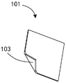
- the positioning connection device 100 can also include a plurality of top spacers 101.
- the top shim 101 is disposed between the top datum plate 110 and the building module 200, that is, between the top datum plate 110 and the frame structure to fill the gap between the top datum plate 110 and the top of the building module 200.
- the upper and lower surfaces of the top shim 101 abut against the top datum plate 110 and the building module 200, respectively, such that the top surfaces of the four top datum plates 110 can remain coplanar to form a top datum plane.
- the thickness of the top shim 101 may be different to facilitate proper placement so that the four top reference plates 110 can remain coplanar. And in the process of positioning the top reference plate 110 described below, the top reference plate 110 can be leveled by means of the top spacer 101. Alternatively, the top shim 101 can be welded to the building module 200 with the top datum plate 110.
- the top shim 101 has a flange 103 for the operator to operate the top shim 101.
- the flange 103 does not interfere with the top reference plate 110.
- a plurality of top spacers 101 are disposed around the edges of the top reference plate 110, and the flanges 103 of the plurality of top spacers 101 also surround the edges of the top reference plate 110. The arrangement is provided so that the operator inserts the top gasket 101 between the top reference plate 110 and the building module 200 by operating the flange 103.
- the bottom corner portion of the building module 200 may be provided with a frame structure to facilitate mounting of the subscript plate 120 to the frame structure.
- the positioning connection device 100 may further include a plurality of bottom spacers 102.
- a bottom shim 102 is disposed between the bottom datum plate 120 and the building module 200, ie, the bottom datum plate 120 and the frame structure, to fill the gap between the bottom datum plate 120 and the bottom of the building module 200.
- the upper and lower surfaces of the top spacer 101 abut against the top reference plate 110 and the building module 200, respectively, so that the bottom surfaces of the four bottom reference plates 120 can remain coplanar to form a bottom reference plane.
- the thickness of the bottom shim 102 may be different to facilitate proper placement so that the four bottom reference plates 120 can remain coplanar.
- the bottom gasket 102 can be welded to the building module 200 with the bottom reference panel 120.
- the bottom spacer 102 has the same structure as the above-mentioned top spacer 101, and details are not described herein again.
- the building module assembly stacked one above the other and/or horizontally side by side is described below.
- the illustrated embodiment exemplarily shows four building module devices, namely two superstructure module devices and two sub-building module devices.
- the building module devices of each floor are arranged side by side, and the building modules 200 in the building module devices stacked one above the other are connected by the positioning connection device 100.
- the building module 200 includes a first building module 210 and a second building module 220 arranged side by side, and a third building module 230 and a fourth building module 240 arranged side by side.
- the first building module 210 is stacked above the third building module 230 and the second building module 220 is stacked above the fourth building module 240.
- first building module 210 and the second building module 220 are superstructure modules
- third building module 230 and the fourth building module 240 are sub-building modules.
- top and bottom of each building module are respectively connected to the top reference plate 110 and the bottom reference plate 120.
- the first building module bottom reference plate 120a corresponds to the third building module top reference plate 110a.
- the second building module bottom reference plate 120b corresponds to the fourth building block top reference plate 110b.
- the bottom surface of the first building module bottom reference plate 120a and the bottom surface of the second building module bottom reference plate 120b are coplanar, i.e., on the same bottom reference plane.
- the top surface of the third building block top reference plate 110a and the top surface of the fourth building block top reference plate 110b are coplanar, i.e., on the same top datum plane.
- a horizontal connector 180 is also included.
- the horizontal connector 180 is preferably plate shaped.
- the horizontal connectors 180 are disposed at the corners of the side-by-side building modules and are disposed between the superstructure module device and the sub-building module device.
- the horizontal connector 180 is disposed on the top reference plate 120 of the superstructure modules (the first and second building modules 210, 220) and the top reference plate of the sub-building modules (the third and fourth building modules 230, 240) Between 110.
- the horizontal connector 180 is parallel and abuts with the first building module bottom reference plate 120a, the second building module bottom reference plate 120b, the third building module top reference plate 110a, and the fourth building module top reference plate 110b.
- the building module device can be connected in the horizontal direction and the connection strength of the positioning connection device 100 can be enhanced.
- the horizontal connectors 180 may overlap the respective reference plates at the corners of each building module.
- the horizontal connector 180 may overlap the first building module bottom reference plate 120a and the second building module bottom reference plate 120b, and the third building module top reference plate 110a and the fourth building module top reference plate 110b.
- the horizontal connector 180 is provided with symmetrically arranged horizontal connector positioning holes and symmetrically arranged horizontal connector connecting holes.
- the horizontal connector locating holes are used for the positioning cone of the top reference plate of the sub-building module to pass through.
- the horizontal connector attachment aperture is for the fastener 170 to pass through.
- the horizontal connector positioning hole includes a first horizontal connector positioning hole 181 and a second horizontal connector positioning hole 182.
- the horizontal connector connecting hole includes a first horizontal connector connecting hole 183 and a second horizontal connector connecting hole 184.
- the first horizontal connector positioning hole 181 and the first horizontal connector connecting hole 183 will be described below as an example.
- the first horizontal connector positioning hole 181 corresponds to the positioning cone 111a of the third building module top reference plate 110a and the bottom positioning large hole 121a of the first building module bottom reference plate 120a.
- the first horizontal connector connecting hole 183 corresponds to the top connecting hole 118a of the third building block top reference plate 110a and the bottom connecting hole 123a of the first building block bottom reference plate 120a.
- the first horizontal connector positioning hole 181 is in clearance fit with the positioning cylindrical surface of the positioning cone 111a of the third building module top reference plate 110a. As described above, the positioning cone 111a of the third building module top reference plate 110a is in clearance engagement with the bottom positioning large hole 121a of the first building module bottom reference plate 120a.
- the positioning cone 111a of the third building block top reference plate 110a can sequentially pass through the first horizontal connector positioning hole 181 and the first building module bottom reference plate 120a.
- the bottom is positioned with a large hole 121a.
- the fastener 170 can pass through the bottom connection hole 123a of the first building module bottom reference plate 120a, the first horizontal connector connection hole 183, and the top connection hole 118a of the third building module top reference plate 110a from the bottom to the bottom, and Connect them together.
- the center axis of the positioning cone 111a of the third building block top reference plate 110a, the center of the first horizontal connector positioning hole 181, and the center line of the bottom positioning large hole 121a of the first building module bottom reference plate 120a coincide.
- the center of the top connection hole 118a of the third building block top reference plate 110a, the center of the first horizontal connector connecting hole, and the center line of the bottom connecting hole 123a of the first building module bottom reference plate 120a coincide.
- the positioning cone 111b of the fourth building block top reference plate 110b can sequentially pass through the second horizontal connecting piece positioning hole 182 and the second building module bottom.
- the bottom of the reference plate 120b is positioned with a large hole 121b.
- the fastener 170 can pass through the bottom connection hole 123b of the second building module bottom reference plate 120b, the second horizontal connector connection hole 184, and the top connection hole 118b of the fourth building module top reference plate 110b from the bottom to the bottom, and Connect them together.
- the second building module 220 and the fourth building module 240 can be joined together.
- the corners of adjacent building modules can be joined together, thereby enabling the connection of the above four building modules.
- the fastener 170 includes a bolt 171, a nut 172, and a stopper 173 that accommodates and limits the position of the nut 172.
- the limiting member 173 is disposed under the top connecting hole of the lower building module top reference plate (for example, the third building block top reference plate 110a), and the limiting member 173 is welded or screwed to the lower building module.
- the top reference plate is fixedly connected.
- the limiting member 173 has a main body 175 and a Z-shaped bending structure 176.
- the bending structure 176 is three, and the three bending structures 176 are circumferentially spaced along the main body 175 of the limiting member 173, and three.
- the angle between any two of the bent structures 176 is 120°.
- the nut 172 is disposed between the lower building module top reference plate and the limiting member 173, so that the lower building module top reference plate and the limiting member 173 restrict the rotation of the nut 172 from loosening and falling off.
- the body of the limiting member 173 may also be provided with a bolt through hole 177 to prevent the limiting member 173 from interfering with the bolt 171.
- Nut 172 is preferably a hex nut.
- the fastener also includes a bolt spacer 174 to reduce wear of the reference plate of the bolt 171 during fastening and to enhance the strength of the bolted connection.
- the corner portion of the building module of the present embodiment may be provided with a top corner piece and a bottom corner piece (refer to FIG. 4), and the top corner piece and the bottom corner piece are transmitted in the lifting, carrying, fixing, and stacking operations of the building module.
- the role of force can also protect building modules.
- the sub-building module top reference plate for example, the third building module bottom reference plate
- the top surface is higher than the top surface of the lower building module corner piece (the third building module corner piece)
- the bottom surface of the superstructure module bottom reference plate for example, the first building module bottom reference plate
- the corner of the building module is the location where the load is mainly transmitted
- the third building module 230 is taken as an example
- the third building module There may be a gap between the corner piece and the horizontal connecting piece 180, so that the corner piece of the third building module can not play the role of transmitting the load, and therefore, the corner piece gasket 105 can be disposed at the corner piece of the third building module (refer to Figure 4).
- the top surface of the corner piece spacer 105 is coplanar with the top surface of the third building module top reference plate 110a such that the corner piece spacer 105 can abut the horizontal connector 180.
- the first building module 210 is taken as an example, between the first building module bottom corner piece and the horizontal connection piece 180 There may be a gap so that the first building module corner piece does not function to transmit the load, and therefore, the corner piece spacer 106 (refer to FIG. 4) may be provided at the bottom corner piece of the first building module.
- the bottom surface of the bottom corner spacer 106 is coplanar with the bottom surface of the first building module bottom reference plate 120a such that the bottom corner spacer 106 can abut the horizontal connector 180.
- the bottom reference plate and the substructure of the superstructure module can be used only by the fastener without providing the horizontal connection member.
- the top reference board of the module is connected.
- the corner piece spacer of the sub-building module can abut the bottom corner piece of the superstructure module.
- the building modular device can be connected to the ground. That is to say, the building module can be connected to the ground through the bottom reference plate.
- the positioning attachment device further includes a foundation positioning cone.
- the foundation positioning cone is placed on the ground.
- the structure of the foundation positioning cone is substantially the same as the structure of the positioning cone in the above, wherein the central axes of the cone, the cone and the cone bottom of the foundation positioning cone coincide.
- the foundation positioning cone can be multiple, and the positions of the plurality of foundation positioning cones can be positioned by the laser positioning instrument of the positioning connection system.
- a plurality of foundation positioning cones respectively correspond to the bottom reference plates of the building module.
- the foundation positioning cone is positioned through the bottom of the bottom reference plate and extends upward.
- the positioning cylindrical surface of one of the foundation positioning cones can cooperate with the first bottom positioning large hole to limit the degree of freedom of the building module in the horizontal direction.
- the positioning cylindrical surface of the other of the foundation positioning cones can cooperate with the wall of the waist hole in the width direction of the hole to limit the remaining rotational freedom of the building module in the horizontal direction.
- the present invention also provides a positioning connection device 100 having the same structure as the positioning connection device in the building module device. For the sake of brevity, no further details are provided herein.
- a positioning system 300 for positioning a positioning connection device 100 to a predetermined position corresponding to the building module 200 in order to position the connection device 100 (ie, the top reference plate 110 and the bottom)
- the reference board 120 is connected to the building module 200.
- the positioning system 300 includes a laser positioning instrument 310 and a tooling station 320.
- the laser positioning instrument 310 cooperates with the tooling station 320 to accurately position the bottom reference plate 120 and the top reference plate 110 in the positioning connector.
- the laser positioning instrument 310 cooperates with the tooling table 320 to position the bottom reference plate 120 to a predetermined position at the bottom (refer to FIG. 13).
- the laser positioning instrument 310 is used to position the top reference plate 110 to the top predetermined Position (refer to Figure 15).
- the laser positioning instrument 310 is a three-dimensional laser positioning instrument.
- the laser positioning instrument 310 is mounted on a high stage 311 outside the tooling station 320.
- Positioning system 300 also includes a laser reflector (not shown) that cooperates with laser positioning instrument 310 and control means for receiving signals from laser positioning instrument 310.
- the laser reflector can be placed at the anchor point to be measured.
- the control device recognizes the position of the anchor point in response to the signal of the laser positioning instrument 310. It can be understood that the laser positioning instrument 310, the laser reflector and the control device of the present embodiment are formed as a laser tracking measurement system.
- the laser positioning instrument 310 can be the origin of the positioning coordinate system, and the laser positioning instrument 310 can calculate the coordinate values of the position of the laser reflector in the positioning coordinate system by laser reflection and software.
- a predetermined reference point can be selected in the positioning coordinate system covered by the laser positioning instrument 310 to facilitate positioning of the bottom reference plate 120 and the top reference plate 110.
- the tooling station 320 is configured to support the bottom reference plate 120 and is capable of moving and adjusting the position of the bottom reference plate 120.
- Tooling station 320 can be a gantry.
- the work station 320 includes a support base 330 and a guide rail 340.
- the guide rails 340 are disposed in a horizontal direction, and the support seats 330 are spaced apart from the guide rails 340 and movable relative to the guide rails 340. Thereby, the support base 330 can be moved in the horizontal direction to adjust the position in the horizontal direction.
- the position of the support base 330 in the vertical direction can be adjusted.
- the support base 330 may be disposed on the guide rail 340 by a lifting assembly (not shown), whereby the support base 330 may be moved in the vertical direction by means of the lifting assembly to adjust the position in the vertical direction.
- adjusting the position in the vertical direction herein includes not only adjusting the lifting position of the support base 330 but also adjusting the position of the support seat 330 (for example, with respect to the horizontal direction).
- the support base 330 is configured to support and position the bottom reference plate 120 of the positioning connection.
- the top surface of the support base 330 is a flat surface for abutting against the bottom reference plate 120.
- Each of the support seats 330 is provided with a tooling cone 331 that protrudes upward.
- Tooling cone 331 is used to pass through bottom reference plate 120 to define the position of bottom reference plate 120.
- the structure of the tooling cone 331 is substantially the same as that of the positioning cone 111 above.
- the tooling cone 331 includes a cone, a cone, and a cone bottom, and the cone bottom is fixedly coupled to the support base 330.
- the bottom of the cone is in transition with the arc of the cone.
- the cone head can be configured as a circular cone or a square cone to serve as a guide during alignment with the bottom positioning aperture 121 of the bottom reference plate 120.
- the tapered head of the tooling cone 331 is provided with a downwardly recessed tooling cone positioning hole 332 for facilitating placement of the laser reflector.
- the center line of the tooling cone positioning hole 332 coincides with the center axis of the tooling cone 331. It should be noted that the position where the tooling cone positioning hole 332 is located can be understood as a positioning point selected for positioning the support base 330.
- the support base 330 can be accurately positioned by means of the tooling cone positioning hole 332. If desired and/or desired, the top surface of the cone can be configured in other suitable shapes to facilitate placement of the laser reflector.
- the cone of the tooling cone 331 can be configured as a cylinder having a positioning cylindrical surface that is continuously arranged in the circumferential direction of the central axis of the cone.
- the central axes of the cone, the cone and the cone of the tooling cone 331 are coincident, which is the central axis of the tooling cone 331.
- the center axis of the tooling cone 331 in the present embodiment extends in the vertical direction.
- the support base 330 may be provided with a support seat notch.
- the bottom reference plate notch 124 is substantially vertically aligned with the support seat notch.
- the tooling cone 331 is disposed adjacent to the support seat notch.
- the support base 330 may not be provided with a support seat notch.
- the illustrated embodiment exemplarily illustrates that the work station 320 is configured to carry a building module 200 through the support base 330 and the bottom reference plate 120.
- the support base 330 includes a first support base 333, a second support base 334, a third support base 335, and a fourth support base 336.
- the first support base 333 and the third support base 335 are arranged along the lateral direction D1 of the tooling table 320.
- the first support base 333 and the fourth support base 336 are diagonally arranged.
- the first bottom reference plate 130, the second bottom reference plate 140, the third bottom reference plate 150, and the fourth bottom reference plate 160 may be sequentially placed on the first support base 333 and the second support base 334.
- the third support base 335 and the fourth support base 336 The tooling cones 331 of the first support base 333, the second support base 334, the third support base 335 and the fourth support base 336 can respectively pass through the first bottom reference plate 130, the second bottom reference plate 140, and the third bottom
- the reference plate 150 and the fourth bottom reference plate 160 define their position on the support base 330.
- the first bottom reference plate 130 may be placed on the first support base 333, and the second bottom reference plate 140, the third bottom reference plate 150, and the fourth bottom reference plate 160 may be placed as needed.
- the guide rail 340 is disposed on the support frame.
- the guide rail 340 includes a first rail 341, a second rail 342 perpendicular to the first rail 341, and a third rail 343 parallel to the second rail 342.
- the second rail 342 is disposed on the first rail 341 and movable relative to the first rail 341.
- At least two of the support seats 330 are disposed on the second guide rail 342.
- the third rail 343 is fixedly disposed, and at least two of the support seats 330 are disposed on the third rail 343.
- the first support base 333 and the second support base 334 are disposed on the third guide rail 343.
- the third support base 335 and the fourth support base 336 are disposed on the second guide rail 342 so as to adjust the positions of the two support bases 330 along the longitudinal direction D2 of the tooling table 320 together.
- Each of the support seats 330 can freely adjust the position along the lateral direction D1 of the tooling table 320.
- movement of the support base 330 relative to the guide rail 340 is achieved by a control device that moves each of the support seats 330 in response to the laser positioning instrument 310, for example, moving a third disposed on the third guide rail 343
- the support base 335 or the second support base 334 and the fourth support base 336 disposed on the second guide rail 342 are moved along the first guide rail 341 by moving the second guide rail 342.
- the control device can also control the second support.
- the seat 334 and the fourth support base 336 move relative to the second rail 342.
- the movement of the support base 330 can also be achieved by manual movement.
- the tooling cones 331 of the first support base 333, the second support base 334, the third support base 335, and the fourth support base 336 have the same shape, and may be configured to be positioned with the first bottom positioning large hole 131.
- the shape is adapted.
- the fitting tolerance of the tooling cone 331 of the first support base 333 and the first bottom positioning large hole 131 is between ⁇ 0.5 mm and ⁇ 1 mm.
- the second bottom positioning large hole 141, the third bottom positioning large hole 151 and the fourth bottom positioning large hole have a larger size (refer to the above) with respect to the first bottom positioning large hole 131, so that when the tooling cones 331 are worn After passing the corresponding bottom reference plate, the second bottom reference plate 140, the third bottom reference plate 150, and the fourth bottom reference plate 160 may be moved in the horizontal direction around the respective tooling cones 331 as needed to adjust the respective horizontal direction positions.
- the second bottom positioning large hole 141 is a waist hole
- the tooling cone 331 of the second support base 334 and the waist hole The tolerance of the hole wall along the width of the hole is between ⁇ 0.5 mm and ⁇ 1 mm.
- the tooling station 320 further includes a positioning pin 351.
- the positioning pin 351 extends upward for extending into the corner piece of the building module 200 in a state where the building module 200 is placed on the work table 320. Specifically, the positioning pin 351 can extend through the corner hole of the bottom corner piece into the corner piece. Thereby, it is possible to play a guiding role in the process of aligning and abutting the building module 200 with the bottom reference plate 120, and restricting the degree of freedom of the building module 200 in the horizontal direction.
- the positioning pin 351 is spaced apart from the corresponding support seat 330.
- FIG. 13 shows that the positioning pin 351 is disposed outside the first support base 333 and spaced apart from the first support base 333.
- the positioning pin 351 is disposed at a notch of the support seat of the first support base 333.
- the positioning pin 351 is fixedly disposed on the positioning pin base 352, and the positioning pin base 352 is spaced apart from the third rail 343 provided with the first support base 333.
- the locating pin base 352 can be fixedly disposed on the ground.
- the work station 320 also includes a limit plate 353.
- the limiting plate 353 extends horizontally toward the corresponding supporting seat 330 for abutting against the bottom corner piece of the building module 200 in a state where the building module 200 is placed on the tooling table 320. Specifically, the position limiting plate 353 can abut against the side surface of the corner piece. Thereby, a further guiding action can be played during the alignment of the building module 200 with the bottom reference plate 120, limiting the degree of freedom of rotation of the building module 200 in the horizontal direction.
- the limiting plate 353 is spaced apart from the corresponding support seat 330.
- FIG. 13 shows that the limiting plate 353 is disposed outside the third support base 335 and spaced apart from the third support base 335.
- the limiting plate 353 is disposed on the limiting plate base 354, and the limiting plate base 354 is spaced apart from the second guiding rail 342 provided with the third supporting base 335.
- the limiting plate base 354 can be moved together with the second guiding rail 342 to maintain the relative position of the limiting plate 353 and the third supporting base 335 along the longitudinal direction D2 of the mounting table 320.
- the work station 320 also includes an additional support 337.
- the additional support base 337 is disposed between the first support base 333 and the third support base 335.
- the additional support base 337 is disposed on the second rail 342 and movable relative to the second rail 342.
- the additional support 337 can support the building module 200.
- the present invention also provides a connection method for a building module that enables the positioning connection device (the top reference plate 110 and the bottom reference plate 120) to be connected to the building module 200 so that the adjacent building module 200 can be passed
- the positioning and connecting device 100 is connected.
- connection method includes the following steps:
- Step S1 The support base 330 of the tooling table 320 is positioned to a position such that the bottom reference plate 120 corresponds to a predetermined position of the bottom portion in accordance with the cooperation of the laser positioning instrument 310 and the tooling table 320.
- the top surface of each of the support seats 330 may be leveled on the same level according to the laser positioning instrument 310. It will be appreciated that the top surface of each of the support seats 330 has the same horizontal coordinate with respect to a predetermined reference point. Specifically, it can be determined whether the height coordinate values of at least three points of each of the top surfaces of the support base 330 are the same according to the signal reflected by the laser reflector placed on the top surface of the support base 330 to adjust the position in the support base 330. The position of the top surface of each one. Alternatively, three to five points of the top surface of the support base 330 may be selected to determine if its top surface is level.
- the present embodiment can level the top surface of the support base 330 by adjusting the position of the support seat 330 in the vertical direction, so that the top surface of each of the support seats 330 can be leveled on the same horizontal plane.
- the top surface of the support base 330 may be first leveled even if the top surface of the support base 330 is horizontal, and then the height of the support base 330 is adjusted by the lift assembly such that the top surface of the support base 330 is at the same horizontal coordinate.
- the leveled support base 330 can be positioned through the positioning point of the support base 330 according to the laser positioning instrument 310.
- the "positioning point" is a fixed point selected on the support base 330 that moves with the support base 330.
- the positioning point is selected at the tooling cone positioning hole 332.
- the laser reflector can be placed at the tooling cone positioning hole 332, and the positioning point of the tooling cone positioning hole 332 is determined to be at a preset coordinate value according to the signal reflected by the laser reflector placed at the tooling cone positioning hole 332. And moving the support base 330 to adjust the position of the positioning point relative to the laser positioning instrument 310.
- the position of the support base 330 is moved in the horizontal direction, and when the positioning point is located at the preset coordinate value, the movement of the support base 330 is stopped. Thereby, the positioning of the support base 330 in the horizontal direction can be achieved.
- the above four support bases 330 can be separately positioned.
- the horizontal position of the support base 330 is achieved by the control device in response to the laser positioning instrument 310 moving the support base 330.
- the present embodiment can move each of the support seats 330 separately to adjust its position on the corresponding rail 340, and can move the second rail 342 to adjust the relative position of the second support base 334 and the fourth support base 336 The position of a support base 333.
- Step S2 The bottom reference plate 120 is placed on the positioned support base 330.
- the bottom positioning large hole 121 of the bottom reference plate 120 is aligned with the tooling cone 331 of the support base 330, and the bottom reference plate 120 is sleeved to the tooling cone 331 by the guiding of the taper head, so that the tool cone can be placed on the tooling cone
- the top surface of 331 Since the thickness of the bottom reference plate 120 is the same, the top surface of each of the bottom reference plates 120 has the same horizontal coordinate with respect to a predetermined reference point.
- Step S3 Positioning the bottom reference plate 120 to a position corresponding to a predetermined position of the bottom according to the laser positioning instrument 310.
- the bottom reference plate 120 can be positioned through the positioning point of the bottom reference plate 120 according to the laser positioning instrument 310. Referring to the above, this positioning point moves together with the bottom reference plate 120.
- the anchor point can be selected at the bottom positioning aperture 122.
- the laser reflector can be placed at the bottom positioning hole 122, and the positioning point at the bottom positioning hole 122 is determined to be at a preset coordinate value according to the signal reflected by the laser reflector placed at the bottom positioning hole 122.
- the position of the positioning point relative to the laser positioning instrument 310 is adjusted by moving the bottom reference plate 120 horizontally around the tooling cone 331. Thereby, the positioning of the bottom reference plate 120 in the horizontal direction can be achieved.
- the above four bottom reference plates 120 can be separately positioned.
- Step S4 The building module 200 is placed on the positioned bottom reference plate 120 and the bottom reference plate 120 is connected to the building module 200.
- step S4 the building module 200 is placed through the positioning pin 351 of the tooling table 320 and/or the limiting plate 353. Specifically, the building module 200 can be placed from the top of the tooling table 320 to the bottom reference plate 120 by hoisting. During the alignment of the bottom portion of the building module 200 with the bottom reference plate 120, the building module 200 is moved to the top surface of the bottom reference plate 120 by means of the positioning pins 351 of the tooling table 320 and the guide plates 353.
- the bottom spacer 102 may be disposed in the building module 200 and the bottom reference plate 120.
- the bottom spacers 102 of different thicknesses may be selected and the position of the bottom spacers 102 may be set as desired such that each of the bottom spacers 102 abuts the building module 200 and the bottom reference panel 120.
- the bottom reference plate 120 is attached to the building module 200.
- the bottom reference plate 120 is welded to the building module 200.
- Step S5 The top reference plate 110 is placed on top of the building module 200, and the top reference plate 110 is positioned and connected to the top predetermined position according to the laser positioning instrument 310.
- the top surface of each of the top reference plates 110 may be leveled on the same level according to the laser positioning instrument 310. It will be appreciated that the top surface of each of the top reference plates 110 has the same horizontal coordinate with respect to a predetermined reference point. Specifically, it can be determined whether the height coordinate values of at least three points of each of the top surfaces of the top reference plate 110 are the same according to the signal reflected by the laser reflector placed on the top surface of the top reference plate 110 to adjust the top reference plate. The position of the top surface of each of the 110s. Alternatively, three to five points of the top surface of the top reference plate 110 may be selected to determine whether the top surface thereof is horizontal.
- the present embodiment can level the top surface of each of the top reference plates 110 by arranging the top spacer 101 between the top reference plate 110 and the building module 200 to level the top surface of the top reference plate 110. On the same level. Considering that the top surface of the building module 200 may be uneven, it is necessary to support the top reference plate 110 by means of the top spacer 101 such that its top surface is horizontal. The top spacer 101 having a different thickness can be selected, and the position of the top spacer 101 can be set as needed.
- the leveled top reference plate 110 may be positioned by at least two positioning points of the top reference plate 110 according to the laser positioning instrument 310.
- the positioning points may be selected at the positioning cone positioning holes 112 and the top positioning small holes 113.
- the laser reflector can be placed at the top positioning small hole 113, and the top positioning small hole 113 is judged according to the signal reflected by the laser reflector placed at the top positioning small hole 113.
- the positioning point is at the preset coordinate value, and horizontally moving the top reference plate 110 around the tooling cone 331 to adjust the position of the positioning point relative to the laser positioning instrument 310.
- the above four top reference plates 110 can be separately positioned.
- the positioned top reference plate 110 is coupled to the building module 200.
- the top reference plate 110 is welded to the building module 200.
- connection method further includes step S6 after step S5: stacking two building modules 200 to which the top reference plate 110 and the bottom reference plate 120 are connected, the bottom reference plate 120 of the superstructure module and the top of the lower building module The reference board 110 is connected.
- the superstructure module (refer to the first building module 210 in FIG. 4) may be moved to the top of the sub-building module (refer to the third building module 230 in FIG. 4) at the bottom reference plate 120 of the superstructure module.
- the bottom positioning large hole 121 of the bottom reference plate 120 of the superstructure module can be set to the lower building module by means of the guiding of the taper head 114 of the positioning cone 111.
- the positioning cone 111 of the top reference plate 110 is positioned to position the superstructure module.
- the top attachment hole 118 of the corresponding top reference plate 110 and the bottom attachment hole 123 of the bottom reference plate 120 are joined by means of fasteners 170 such as bolts.
- connection method further includes step S7 after step S5: horizontally setting two building modules 200 to which the top reference plate 110 and the bottom reference plate 120 are connected, and the top reference plates 110 of the adjacent building modules are horizontally connected Piece 180 is connected.
- the two building modules 200 may be arranged side by side and aligned, and then the horizontal connecting member positioning holes of the horizontal connecting member 180 are respectively sleeved.
- Positioning cones 111 of the top reference plates 110 of the respective building modules 200 are provided to position the horizontal connectors 180.
- step S7 may be performed first, followed by step S6.
- the superstructure module can be placed over the sub-building module.
- the positioning cone 111 of the top reference plate 110 of the sub-building module can pass through the horizontal connector positioning hole of the horizontal connector 180 and the bottom reference plate 120 of the superstructure module.
- top connecting hole 118 of the top reference plate 110, the horizontal connecting piece positioning hole of the horizontal connecting member 180 and the bottom connecting hole 123 of the bottom reference plate 120 are correspondingly connected by means of a fastener 170 such as a bolt, To form a stacked building module device.
Abstract
Description
Claims (16)
- 一种建筑模块装置,其特征在于,所述建筑模块装置包括建筑模块和连接至所述建筑模块的定位连接装置,所述定位连接装置包括:A building module device, characterized in that the building module device comprises a building module and a positioning connection device connected to the building module, the positioning connection device comprising:顶基准板,所述顶基准板设置有顶定位孔,所述顶基准板用于连接至所述建筑模块的顶部;和a top reference plate, the top reference plate being provided with a top positioning hole for connecting to a top of the building module; and底基准板,所述底基准板设置有底定位孔,所述底基准板用于连接至所述建筑模块的底部,a bottom reference plate, the bottom reference plate is provided with a bottom positioning hole for connecting to a bottom of the building module,其中,所述顶基准板通过所述顶定位孔定位至顶部预定位置,所述底基准板通过所述底定位孔定位至底部预定位置,所述顶部预定位置和所述底部预定位置相对于预定基准点具有相同的水平坐标位置且竖直相对布置。Wherein the top reference plate is positioned to a top predetermined position by the top positioning hole, and the bottom reference plate is positioned to a bottom predetermined position by the bottom positioning hole, the top predetermined position and the bottom predetermined position being opposite to a predetermined position The reference points have the same horizontal coordinate position and are arranged vertically opposite each other.
- 根据权利要求1所述的建筑模块装置,其特征在于,所述建筑模块为至少两个,所述至少两个建筑模块通过分别定位至顶部预定位置和底部预定位置的所述顶基准板和底基准板紧固连接在一起。The building modular device according to claim 1, wherein said building modules are at least two, said at least two building modules being passed to said top reference plate and bottom respectively positioned to a top predetermined position and a bottom predetermined position The reference plates are fastened together.
- 根据权利要求2所述的建筑模块装置,其特征在于,还包括水平连接件,以便将两个所述建筑模块在水平方向上连接。The building modular device of claim 2 further comprising a horizontal connector for connecting the two building modules in a horizontal direction.
- 根据权利要求1所述的建筑模块装置,其特征在于,所述建筑模块通过所述底基准板与地面连接在一起。The building modular device of claim 1 wherein said building module is coupled to the ground by said bottom reference panel.
- 根据权利要求1所述的建筑模块装置,其特征在于,位于所述顶部预定位置的所述顶基准板和位于所述底部预定位置的所述底基准板沿所述建筑模块的高度方向的投影重合。The building modular device according to claim 1, wherein a projection of said top reference plate at said top predetermined position and said bottom reference plate at said bottom predetermined position along a height direction of said building module coincide.
- 根据权利要求1所述的建筑模块装置,其特征在于,The building module device according to claim 1, wherein所述顶基准板为多个,多个所述顶基准板的顶表面共面以形成顶基准平面;并且The top reference plate is a plurality of, the top surfaces of the plurality of the top reference plates being coplanar to form a top reference plane;所述底基准板为多个,多个所述底基准板的底表面共面以形成底基准平面。The bottom reference plate is a plurality of, and the bottom surfaces of the plurality of the bottom reference plates are coplanar to form a bottom reference plane.
- 根据权利要求6所述的建筑模块装置,其特征在于,A building module device according to claim 6 wherein:所述建筑模块设置有顶角件,所述顶基准板的角部具有缺口,所述缺口用于与所述顶角件相匹配以容纳所述顶角件;并且/或者The building module is provided with a corner piece, the corner of the top reference plate having a notch for matching the top corner piece to accommodate the top corner piece; and/or所述建筑模块设置有底角件,所述底基准板的角部具有缺口,所述缺口用于与所述底角件相匹配以容纳所述底角件。The building module is provided with a bottom corner piece, the corner of the bottom reference plate having a notch for matching the bottom corner piece to accommodate the bottom corner piece.
- 根据权利要求6所述的建筑模块装置,其特征在于,A building module device according to claim 6 wherein:所述建筑模块设置有顶角件,所述顶基准板的顶表面高于所述顶角件的顶表面;并且/或者The building module is provided with a top corner piece, a top surface of the top reference plate being higher than a top surface of the top corner piece; and/or所述建筑模块设置有底角件,所述底基准板的底表面低于所述底角件的底表面。The building module is provided with a bottom corner piece, the bottom surface of the bottom reference plate being lower than the bottom surface of the bottom corner piece.
- 根据权利要求6所述的建筑模块装置,其特征在于,A building module device according to claim 6 wherein:所述建筑模块设置有顶角件,所述顶基准板的顶表面高于所述顶角件的顶表面,所述顶角件处设置有顶角件垫片,以使得所述顶角件垫片的顶表面与所述顶基准板的顶表面共面;并且/或者The building module is provided with a top corner piece, a top surface of the top reference plate is higher than a top surface of the top corner piece, and a top corner piece is disposed at the top corner piece, so that the top corner piece The top surface of the gasket is coplanar with the top surface of the top reference plate; and/or所述建筑模块设置有底角件,所述底基准板的底表面低于所述底角件的底表面,所述底角件处设置有底角件垫片,以使得所述底角件垫片的底表面与所述底基准板的底表面共面。The building module is provided with a bottom corner piece, a bottom surface of the bottom reference plate is lower than a bottom surface of the bottom corner piece, and a bottom corner piece is disposed at the bottom corner piece, so that the bottom corner piece The bottom surface of the gasket is coplanar with the bottom surface of the bottom reference plate.
- 一种用于建筑模块的定位连接装置,其特征在于,所述定位连接装置包括:A positioning and connecting device for a building module, characterized in that the positioning and connecting device comprises:顶基准板,所述顶基准板设置有顶定位孔,所述顶基准板用于连接至所述建筑模块的顶部;和a top reference plate, the top reference plate being provided with a top positioning hole for connecting to a top of the building module; and底基准板,所述底基准板设置有底定位孔,所述底基准板用于连接至所述建筑模块的底部,a bottom reference plate, the bottom reference plate is provided with a bottom positioning hole for connecting to a bottom of the building module,其中,所述顶基准板通过所述顶定位孔定位至顶部预定位置,所述底基准板通过所述底定位孔定位至底部预定位置,所述顶部预定位置和所述底部预定位置相对于预定基准点具有相同的水平坐标位置且竖直相对布置。Wherein the top reference plate is positioned to a top predetermined position by the top positioning hole, and the bottom reference plate is positioned to a bottom predetermined position by the bottom positioning hole, the top predetermined position and the bottom predetermined position being opposite to a predetermined position The reference points have the same horizontal coordinate position and are arranged vertically opposite each other.
- 根据权利要求10所述的定位连接装置,其特征在于,所述顶基准板为多个,每一所述顶基准板均设置有定位锥,每一所述顶基准板的所述顶定位孔包括设置于所述定位锥顶部的定位锥定位孔,和设置于所述顶基准板的顶定位小孔,所述定位锥用于延伸穿过另一个所述定位连接装置的所述底基准板。The positioning connection device according to claim 10, wherein the top reference plates are plurality, each of the top reference plates is provided with a positioning cone, and the top positioning hole of each of the top reference plates a positioning cone positioning hole disposed at a top of the positioning cone, and a top positioning aperture disposed on the top reference plate, the positioning cone for extending through the bottom reference plate of another positioning connection device .
- 根据权利要求11所述的定位连接装置,其特征在于,每一所述顶基准板均包括顶定位大孔,所述定位锥可拆卸地固定至所述顶定位大孔,所述定位锥的中心轴线与所述顶定位大孔的中心线重合。The positioning connection device according to claim 11, wherein each of the top reference plates comprises a top positioning large hole, and the positioning cone is detachably fixed to the top positioning large hole, the positioning cone The central axis coincides with the centerline of the top positioning macrohole.
- 根据权利要求11所述的定位连接装置,其特征在于,所述底基准 板为多个,每一所述底基准板的所述底定位孔包括底定位大孔和底定位小孔。The positioning connection device according to claim 11, wherein the bottom reference plate is a plurality, and the bottom positioning holes of each of the bottom reference plates comprise a bottom positioning large hole and a bottom positioning small hole.
- 根据权利要求13所述的定位连接装置,其特征在于,多个所述底基准板包括:The positioning connection device according to claim 13, wherein the plurality of said bottom reference plates comprise:至少一个第一底基准板,所述第一底基准板的底定位大孔用于与另一个所述定位连接装置的所述定位锥或设置在工装台上的工装锥间隙配合,配合公差在±0.5mm至±1mm之间;At least one first bottom reference plate, the bottom positioning large hole of the first bottom reference plate is used for clearance with the positioning cone of another positioning connection device or the tooling cone disposed on the tooling table, and the tolerance is Between ±0.5mm and ±1mm;至少一个第二底基准板,所述第二底基准板的底定位大孔为腰型孔,所述腰型孔用于与另一个所述定位连接装置的所述定位锥或设置在工装台上的工装锥间隙配合,所述腰型孔在孔宽度方向的孔壁与所述定位锥或工装锥的配合公差在±0.5mm至±1mm之间。At least one second bottom reference plate, the bottom positioning large hole of the second bottom reference plate is a waist hole, and the waist hole is used for the positioning cone with another positioning connection device or at the tooling station The upper tooling cone clearance fits, and the matching tolerance of the waist hole in the hole width direction with the positioning cone or the tooling cone is between ±0.5 mm and ±1 mm.
- 根据权利要求14所述的定位连接装置,其特征在于,多个所述底基准板还包括:The positioning connection device according to claim 14, wherein the plurality of the bottom reference plates further comprise:第三底基准板,所述第三底基准板的底定位大孔用于与另一个所述定位连接装置的所述定位锥或设置在工装台上的工装锥间隙配合,所述第三底基准板的底定位大孔的直径大于所述第一底基准板的底定位大孔的直径。a third bottom reference plate, the bottom positioning large hole of the third bottom reference plate is used for clearance with the positioning cone of another positioning connection device or a tooling cone disposed on the tooling table, the third bottom The diameter of the bottom positioning macro hole of the reference plate is larger than the diameter of the bottom positioning large hole of the first bottom reference plate.
- 根据权利要求10所述的定位连接装置,其特征在于,所述底基准板还包括底连接孔,所述顶基准板还包括顶连接孔;The positioning connection device according to claim 10, wherein the bottom reference plate further comprises a bottom connection hole, and the top reference plate further comprises a top connection hole;所述底连接孔用于供紧固件穿过,以将所述底基准板与另一个所述定位连接装置的所述顶基准板连接;和The bottom attachment hole is for a fastener to pass through to connect the bottom reference plate to the top reference plate of another of the positioning connection devices; and所述顶连接孔用于供紧固件穿过,以将所述顶基准板与另一个所述定位连接装置的所述底基准板连接。The top attachment hole is for a fastener to pass through to connect the top reference plate to the bottom reference plate of another of the positioning connectors.
Priority Applications (2)
| Application Number | Priority Date | Filing Date | Title |
|---|---|---|---|
| AU2018334897A AU2018334897B2 (en) | 2017-09-22 | 2018-09-21 | Positioning connection device and building module device |
| GB2005862.4A GB2581288B (en) | 2017-09-22 | 2018-09-21 | Positioning connecting device and building module device |
Applications Claiming Priority (2)
| Application Number | Priority Date | Filing Date | Title |
|---|---|---|---|
| CN201710868354.1A CN107675895A (en) | 2017-09-22 | 2017-09-22 | Locating connector, the system that is located by connecting, building block device and connection method |
| CN201710868354.1 | 2017-09-22 |
Publications (1)
| Publication Number | Publication Date |
|---|---|
| WO2019057147A1 true WO2019057147A1 (en) | 2019-03-28 |
Family
ID=61136991
Family Applications (3)
| Application Number | Title | Priority Date | Filing Date |
|---|---|---|---|
| PCT/CN2018/106915 WO2019057147A1 (en) | 2017-09-22 | 2018-09-21 | Positioning connection device and building module device |
| PCT/CN2018/106935 WO2019057149A1 (en) | 2017-09-22 | 2018-09-21 | Positioning system for building modules |
| PCT/CN2018/107004 WO2019057162A1 (en) | 2017-09-22 | 2018-09-21 | Connecting method for building module |
Family Applications After (2)
| Application Number | Title | Priority Date | Filing Date |
|---|---|---|---|
| PCT/CN2018/106935 WO2019057149A1 (en) | 2017-09-22 | 2018-09-21 | Positioning system for building modules |
| PCT/CN2018/107004 WO2019057162A1 (en) | 2017-09-22 | 2018-09-21 | Connecting method for building module |
Country Status (4)
| Country | Link |
|---|---|
| CN (6) | CN107675895A (en) |
| AU (1) | AU2018334897B2 (en) |
| GB (1) | GB2581288B (en) |
| WO (3) | WO2019057147A1 (en) |
Families Citing this family (9)
| Publication number | Priority date | Publication date | Assignee | Title |
|---|---|---|---|---|
| CN107675895A (en) * | 2017-09-22 | 2018-02-09 | 中集模块化建筑投资有限公司 | Locating connector, the system that is located by connecting, building block device and connection method |
| US11118348B2 (en) * | 2019-01-24 | 2021-09-14 | Invent To Build Inc. | Alignment assembly for panels |
| CN111691290B (en) * | 2020-07-07 | 2021-10-29 | 中交一公局海威工程建设有限公司 | Beam and upright column butt joint method |
| CN114059784B (en) * | 2020-08-06 | 2022-12-30 | 广东博智林机器人有限公司 | Wallboard mounting system and control method thereof |
| CN112338839B (en) * | 2020-10-10 | 2022-04-19 | 扬州泰利特种装备有限公司 | Assembly table and assembly method |
| CN112282391B (en) * | 2020-10-24 | 2022-06-28 | 北京弘洁建设集团有限公司 | Row junction box positioning die and construction method |
| CN114687568A (en) * | 2020-12-29 | 2022-07-01 | 新沂三一筑工有限公司 | Integrated deviation rectifying wheel for prefabricated concrete members of prefabricated building |
| CN112922352B (en) * | 2021-02-01 | 2022-07-15 | 青岛穗禾集成房屋有限公司 | Construction and assembly method for light steel structure prefabricated house |
| CN114908882B (en) * | 2022-05-23 | 2023-11-10 | 广东中集建筑制造有限公司 | Connection positioning system of box building module and modularized building with same |
Citations (5)
| Publication number | Priority date | Publication date | Assignee | Title |
|---|---|---|---|---|
| CA2703401A1 (en) * | 2010-05-11 | 2011-11-11 | William Dewson Architects Inc. | Construction joints and related connectors |
| CN204163193U (en) * | 2014-08-29 | 2015-02-18 | 广东新会中集特种运输设备有限公司 | A kind of modular architectural connector and building |
| CN106609601A (en) * | 2015-10-21 | 2017-05-03 | 扬州通利冷藏集装箱有限公司 | Container modularized building |
| CN107675895A (en) * | 2017-09-22 | 2018-02-09 | 中集模块化建筑投资有限公司 | Locating connector, the system that is located by connecting, building block device and connection method |
| CN207260614U (en) * | 2017-09-22 | 2018-04-20 | 中集模块化建筑投资有限公司 | Locating connector, the system that is located by connecting and building block device |
Family Cites Families (28)
| Publication number | Priority date | Publication date | Assignee | Title |
|---|---|---|---|---|
| US3631648A (en) * | 1970-01-23 | 1972-01-04 | Stirling Homex Corp | Method of erection of high-rise building structure formed of modular units |
| JPS5147970B2 (en) * | 1972-09-19 | 1976-12-17 | ||
| CH560296A5 (en) * | 1973-04-25 | 1975-03-27 | Credelca Ag | |
| JPS5096850A (en) * | 1973-12-27 | 1975-08-01 | ||
| JPS52171106U (en) * | 1976-06-19 | 1977-12-26 | ||
| JPS6141852Y2 (en) * | 1981-01-16 | 1986-11-28 | ||
| JPS6035801U (en) * | 1983-08-20 | 1985-03-12 | トヨタ自動車株式会社 | Inter-unit coupling device |
| JPH0557114A (en) * | 1991-01-11 | 1993-03-09 | Millipore Corp | Highly efficient method for capillary electrophoretic separation |
| JPH05106282A (en) * | 1991-10-16 | 1993-04-27 | Misawa Homes Co Ltd | Coupling device of housing unit |
| JPH0557114U (en) * | 1992-01-16 | 1993-07-30 | ミサワホーム株式会社 | Unit building |
| JPH06306955A (en) * | 1993-04-26 | 1994-11-01 | Sekisui Chem Co Ltd | Column connector of unit structure for building and connecting structure of column using this connector |
| JPH07180229A (en) * | 1993-12-24 | 1995-07-18 | Misawa Homes Co Ltd | Vertical connecting tool of building unit |
| JPH07300902A (en) * | 1994-05-10 | 1995-11-14 | Sekisui Chem Co Ltd | Connection device for column |
| JPH08189088A (en) * | 1995-01-10 | 1996-07-23 | Misawa Homes Co Ltd | Vibration control structure of unit type building |
| JP3014203U (en) * | 1995-02-01 | 1995-08-08 | ミサワホーム株式会社 | Building unit connection structure |
| JPH1018422A (en) * | 1996-06-28 | 1998-01-20 | Sekisui Chem Co Ltd | Post connecting structure |
| JP2002285637A (en) * | 2001-03-26 | 2002-10-03 | Sekisui Chem Co Ltd | Column base fixing structure and unit building |
| JP3655584B2 (en) * | 2001-12-21 | 2005-06-02 | コマツハウス株式会社 | Column structure of building unit |
| JP4642377B2 (en) * | 2004-04-30 | 2011-03-02 | ミサワホーム株式会社 | Building unit fastening structure |
| CN101508100B (en) * | 2009-01-23 | 2012-07-04 | 东华大学 | Exact alignment device of sheet assembling tool set |
| KR20110053101A (en) * | 2009-11-13 | 2011-05-19 | 문근환 | Combination structure of fabricated architecture |
| CN101881080A (en) * | 2010-06-17 | 2010-11-10 | 哈尔滨工业大学深圳研究生院 | Multi-storey container house construction method based on security assessment and multi-storey container house |
| JP2012007350A (en) * | 2010-06-24 | 2012-01-12 | Kita Kikai Sangyo Kk | Unit house |
| TWI476315B (en) * | 2011-05-18 | 2015-03-11 | Ind Tech Res Inst | Assembling component |
| CN203669098U (en) * | 2013-12-23 | 2014-06-25 | 大连中集物流装备有限公司 | Modular building |
| CN104847127B (en) * | 2015-04-21 | 2016-12-07 | 中国科学院长春光学精密机械与物理研究所 | A kind of space optical remote sensor space truss structure precision is debug and is used six-dimensional adjusting support |
| EP3334868B1 (en) * | 2015-08-14 | 2023-07-19 | Z-Modular Holding, Inc | Connector for a modular building |
| CN105401732B (en) * | 2016-02-03 | 2018-03-23 | 中国核工业华兴建设有限公司 | A kind of assemble method of nuclear power station large-sized steel construction module |
-
2017
- 2017-09-22 CN CN201710868354.1A patent/CN107675895A/en active Pending
-
2018
- 2018-09-21 WO PCT/CN2018/106915 patent/WO2019057147A1/en active Application Filing
- 2018-09-21 WO PCT/CN2018/106935 patent/WO2019057149A1/en active Application Filing
- 2018-09-21 CN CN201811106102.6A patent/CN109537916A/en active Pending
- 2018-09-21 AU AU2018334897A patent/AU2018334897B2/en active Active
- 2018-09-21 GB GB2005862.4A patent/GB2581288B/en active Active
- 2018-09-21 CN CN201821562257.6U patent/CN209323681U/en active Active
- 2018-09-21 WO PCT/CN2018/107004 patent/WO2019057162A1/en active Application Filing
- 2018-09-21 CN CN201811106111.5A patent/CN109537715A/en active Pending
- 2018-09-21 CN CN201811106067.8A patent/CN109537730B/en active Active
- 2018-09-21 CN CN201821557933.0U patent/CN209324003U/en active Active
Patent Citations (5)
| Publication number | Priority date | Publication date | Assignee | Title |
|---|---|---|---|---|
| CA2703401A1 (en) * | 2010-05-11 | 2011-11-11 | William Dewson Architects Inc. | Construction joints and related connectors |
| CN204163193U (en) * | 2014-08-29 | 2015-02-18 | 广东新会中集特种运输设备有限公司 | A kind of modular architectural connector and building |
| CN106609601A (en) * | 2015-10-21 | 2017-05-03 | 扬州通利冷藏集装箱有限公司 | Container modularized building |
| CN107675895A (en) * | 2017-09-22 | 2018-02-09 | 中集模块化建筑投资有限公司 | Locating connector, the system that is located by connecting, building block device and connection method |
| CN207260614U (en) * | 2017-09-22 | 2018-04-20 | 中集模块化建筑投资有限公司 | Locating connector, the system that is located by connecting and building block device |
Also Published As
| Publication number | Publication date |
|---|---|
| GB2581288A (en) | 2020-08-12 |
| WO2019057162A1 (en) | 2019-03-28 |
| CN109537715A (en) | 2019-03-29 |
| CN109537730A (en) | 2019-03-29 |
| CN209323681U (en) | 2019-08-30 |
| AU2018334897A1 (en) | 2020-05-07 |
| CN109537730B (en) | 2022-10-18 |
| CN107675895A (en) | 2018-02-09 |
| CN209324003U (en) | 2019-08-30 |
| WO2019057149A1 (en) | 2019-03-28 |
| AU2018334897B2 (en) | 2022-03-24 |
| GB202005862D0 (en) | 2020-06-03 |
| GB2581288B (en) | 2023-01-11 |
| CN109537916A (en) | 2019-03-29 |
Similar Documents
| Publication | Publication Date | Title |
|---|---|---|
| WO2019057147A1 (en) | Positioning connection device and building module device | |
| JP7289048B2 (en) | structural modular building connectors | |
| KR102526136B1 (en) | Modular building units, and methods of constructing and transporting same | |
| JP2013245501A (en) | Connection structure of unit structure | |
| CN105672539A (en) | Stone back bolt pendant and using method thereof | |
| US3977147A (en) | Flanged major modular assembly jig | |
| JP2870513B2 (en) | A method of aligning the core of a steel column with the foundation concrete | |
| CN114908882A (en) | Connecting and positioning system of box type building module and modular building with same | |
| KR20040051556A (en) | Beam connecting structure for building | |
| CN111305420A (en) | Connection structure and precast concrete wallboard system | |
| KR102298974B1 (en) | Jig apparatus for vehicle and method of fixing object using the same | |
| JPS6030324Y2 (en) | Beam attachment device | |
| CN214565297U (en) | Steel structure adjusting mechanism for suspension walking shaft | |
| CN210763789U (en) | Vertical clamping connection board of elevator track | |
| JP2000320148A (en) | Panel positioning jig | |
| CN113338540A (en) | Assembled PEC post installation node structure and frock | |
| CN113250446A (en) | Support device and formwork frame | |
| JP2001123540A (en) | Jointing method and construction of building unit, and connecting board | |
| CN117868301A (en) | Butt joint device and butt joint method for steel beams | |
| CN115890101A (en) | Welding tool and welding positioning method | |
| CN117489927A (en) | Three-dimensional distributed load reduction erection structure, erection system and erection method | |
| JP4685551B2 (en) | Panel connecting member | |
| JPH0141549B2 (en) | ||
| JP2001123537A (en) | Installation and adjustment jig for building unit and installation method | |
| JPH08144377A (en) | Structure and method for positioning and connecting accessory unit |
Legal Events
| Date | Code | Title | Description |
|---|---|---|---|
| 121 | Ep: the epo has been informed by wipo that ep was designated in this application |
Ref document number: 18858688 Country of ref document: EP Kind code of ref document: A1 |
|
| NENP | Non-entry into the national phase |
Ref country code: DE |
|
| ENP | Entry into the national phase |
Ref document number: 202005862 Country of ref document: GB Kind code of ref document: A Free format text: PCT FILING DATE = 20180921 |
|
| ENP | Entry into the national phase |
Ref document number: 2018334897 Country of ref document: AU Date of ref document: 20180921 Kind code of ref document: A |
|
| 32PN | Ep: public notification in the ep bulletin as address of the adressee cannot be established |
Free format text: NOTING OF LOSS OF RIGHTS PURSUANT TO RULE 112(1) EPC (EPO FORM 1205A DATED 19/08/2020) |
|
| 122 | Ep: pct application non-entry in european phase |
Ref document number: 18858688 Country of ref document: EP Kind code of ref document: A1 |