WO2019049790A1 - 船舶 - Google Patents
船舶 Download PDFInfo
- Publication number
- WO2019049790A1 WO2019049790A1 PCT/JP2018/032407 JP2018032407W WO2019049790A1 WO 2019049790 A1 WO2019049790 A1 WO 2019049790A1 JP 2018032407 W JP2018032407 W JP 2018032407W WO 2019049790 A1 WO2019049790 A1 WO 2019049790A1
- Authority
- WO
- WIPO (PCT)
- Prior art keywords
- engine
- lpg
- fuel
- pressure
- pump
- Prior art date
- Legal status (The legal status is an assumption and is not a legal conclusion. Google has not performed a legal analysis and makes no representation as to the accuracy of the status listed.)
- Ceased
Links
Images

Classifications
-
- B—PERFORMING OPERATIONS; TRANSPORTING
- B63—SHIPS OR OTHER WATERBORNE VESSELS; RELATED EQUIPMENT
- B63B—SHIPS OR OTHER WATERBORNE VESSELS; EQUIPMENT FOR SHIPPING
- B63B17/00—Vessels parts, details, or accessories, not otherwise provided for
- B63B17/0027—Tanks for fuel or the like ; Accessories therefor, e.g. tank filler caps
-
- B—PERFORMING OPERATIONS; TRANSPORTING
- B63—SHIPS OR OTHER WATERBORNE VESSELS; RELATED EQUIPMENT
- B63B—SHIPS OR OTHER WATERBORNE VESSELS; EQUIPMENT FOR SHIPPING
- B63B25/00—Load-accommodating arrangements, e.g. stowing, trimming; Vessels characterised thereby
- B63B25/02—Load-accommodating arrangements, e.g. stowing, trimming; Vessels characterised thereby for bulk goods
- B63B25/08—Load-accommodating arrangements, e.g. stowing, trimming; Vessels characterised thereby for bulk goods fluid
- B63B25/12—Load-accommodating arrangements, e.g. stowing, trimming; Vessels characterised thereby for bulk goods fluid closed
- B63B25/16—Load-accommodating arrangements, e.g. stowing, trimming; Vessels characterised thereby for bulk goods fluid closed heat-insulated
-
- B—PERFORMING OPERATIONS; TRANSPORTING
- B63—SHIPS OR OTHER WATERBORNE VESSELS; RELATED EQUIPMENT
- B63H—MARINE PROPULSION OR STEERING
- B63H21/00—Use of propulsion power plant or units on vessels
- B63H21/38—Apparatus or methods specially adapted for use on marine vessels, for handling power plant or unit liquids, e.g. lubricants, coolants, fuels or the like
-
- F—MECHANICAL ENGINEERING; LIGHTING; HEATING; WEAPONS; BLASTING
- F02—COMBUSTION ENGINES; HOT-GAS OR COMBUSTION-PRODUCT ENGINE PLANTS
- F02B—INTERNAL-COMBUSTION PISTON ENGINES; COMBUSTION ENGINES IN GENERAL
- F02B43/00—Engines characterised by operating on gaseous fuels; Plants including such engines
-
- F—MECHANICAL ENGINEERING; LIGHTING; HEATING; WEAPONS; BLASTING
- F02—COMBUSTION ENGINES; HOT-GAS OR COMBUSTION-PRODUCT ENGINE PLANTS
- F02D—CONTROLLING COMBUSTION ENGINES
- F02D41/00—Electrical control of supply of combustible mixture or its constituents
- F02D41/0025—Controlling engines characterised by use of non-liquid fuels, pluralities of fuels, or non-fuel substances added to the combustible mixtures
-
- F—MECHANICAL ENGINEERING; LIGHTING; HEATING; WEAPONS; BLASTING
- F02—COMBUSTION ENGINES; HOT-GAS OR COMBUSTION-PRODUCT ENGINE PLANTS
- F02M—SUPPLYING COMBUSTION ENGINES IN GENERAL WITH COMBUSTIBLE MIXTURES OR CONSTITUENTS THEREOF
- F02M21/00—Apparatus for supplying engines with non-liquid fuels, e.g. gaseous fuels stored in liquid form
- F02M21/02—Apparatus for supplying engines with non-liquid fuels, e.g. gaseous fuels stored in liquid form for gaseous fuels
- F02M21/0218—Details on the gaseous fuel supply system, e.g. tanks, valves, pipes, pumps, rails, injectors or mixers
- F02M21/0221—Fuel storage reservoirs, e.g. cryogenic tanks
-
- F—MECHANICAL ENGINEERING; LIGHTING; HEATING; WEAPONS; BLASTING
- F02—COMBUSTION ENGINES; HOT-GAS OR COMBUSTION-PRODUCT ENGINE PLANTS
- F02M—SUPPLYING COMBUSTION ENGINES IN GENERAL WITH COMBUSTIBLE MIXTURES OR CONSTITUENTS THEREOF
- F02M21/00—Apparatus for supplying engines with non-liquid fuels, e.g. gaseous fuels stored in liquid form
- F02M21/02—Apparatus for supplying engines with non-liquid fuels, e.g. gaseous fuels stored in liquid form for gaseous fuels
- F02M21/0218—Details on the gaseous fuel supply system, e.g. tanks, valves, pipes, pumps, rails, injectors or mixers
- F02M21/023—Valves; Pressure or flow regulators in the fuel supply or return system
- F02M21/0242—Shut-off valves; Check valves; Safety valves; Pressure relief valves
-
- F—MECHANICAL ENGINEERING; LIGHTING; HEATING; WEAPONS; BLASTING
- F02—COMBUSTION ENGINES; HOT-GAS OR COMBUSTION-PRODUCT ENGINE PLANTS
- F02M—SUPPLYING COMBUSTION ENGINES IN GENERAL WITH COMBUSTIBLE MIXTURES OR CONSTITUENTS THEREOF
- F02M21/00—Apparatus for supplying engines with non-liquid fuels, e.g. gaseous fuels stored in liquid form
- F02M21/02—Apparatus for supplying engines with non-liquid fuels, e.g. gaseous fuels stored in liquid form for gaseous fuels
- F02M21/0218—Details on the gaseous fuel supply system, e.g. tanks, valves, pipes, pumps, rails, injectors or mixers
- F02M21/0245—High pressure fuel supply systems; Rails; Pumps; Arrangement of valves
-
- F—MECHANICAL ENGINEERING; LIGHTING; HEATING; WEAPONS; BLASTING
- F02—COMBUSTION ENGINES; HOT-GAS OR COMBUSTION-PRODUCT ENGINE PLANTS
- F02M—SUPPLYING COMBUSTION ENGINES IN GENERAL WITH COMBUSTIBLE MIXTURES OR CONSTITUENTS THEREOF
- F02M37/00—Apparatus or systems for feeding liquid fuel from storage containers to carburettors or fuel-injection apparatus; Arrangements for purifying liquid fuel specially adapted for, or arranged on, internal-combustion engines
-
- F—MECHANICAL ENGINEERING; LIGHTING; HEATING; WEAPONS; BLASTING
- F17—STORING OR DISTRIBUTING GASES OR LIQUIDS
- F17C—VESSELS FOR CONTAINING OR STORING COMPRESSED, LIQUEFIED OR SOLIDIFIED GASES; FIXED-CAPACITY GAS-HOLDERS; FILLING VESSELS WITH, OR DISCHARGING FROM VESSELS, COMPRESSED, LIQUEFIED, OR SOLIDIFIED GASES
- F17C13/00—Details of vessels or of the filling or discharging of vessels
- F17C13/02—Special adaptations of indicating, measuring, or monitoring equipment
- F17C13/025—Special adaptations of indicating, measuring, or monitoring equipment having the pressure as the parameter
-
- F—MECHANICAL ENGINEERING; LIGHTING; HEATING; WEAPONS; BLASTING
- F17—STORING OR DISTRIBUTING GASES OR LIQUIDS
- F17C—VESSELS FOR CONTAINING OR STORING COMPRESSED, LIQUEFIED OR SOLIDIFIED GASES; FIXED-CAPACITY GAS-HOLDERS; FILLING VESSELS WITH, OR DISCHARGING FROM VESSELS, COMPRESSED, LIQUEFIED, OR SOLIDIFIED GASES
- F17C13/00—Details of vessels or of the filling or discharging of vessels
- F17C13/04—Arrangement or mounting of valves
-
- F—MECHANICAL ENGINEERING; LIGHTING; HEATING; WEAPONS; BLASTING
- F17—STORING OR DISTRIBUTING GASES OR LIQUIDS
- F17C—VESSELS FOR CONTAINING OR STORING COMPRESSED, LIQUEFIED OR SOLIDIFIED GASES; FIXED-CAPACITY GAS-HOLDERS; FILLING VESSELS WITH, OR DISCHARGING FROM VESSELS, COMPRESSED, LIQUEFIED, OR SOLIDIFIED GASES
- F17C6/00—Methods and apparatus for filling vessels not under pressure with liquefied or solidified gases
-
- F—MECHANICAL ENGINEERING; LIGHTING; HEATING; WEAPONS; BLASTING
- F17—STORING OR DISTRIBUTING GASES OR LIQUIDS
- F17C—VESSELS FOR CONTAINING OR STORING COMPRESSED, LIQUEFIED OR SOLIDIFIED GASES; FIXED-CAPACITY GAS-HOLDERS; FILLING VESSELS WITH, OR DISCHARGING FROM VESSELS, COMPRESSED, LIQUEFIED, OR SOLIDIFIED GASES
- F17C9/00—Methods or apparatus for discharging liquefied or solidified gases from vessels not under pressure
-
- F—MECHANICAL ENGINEERING; LIGHTING; HEATING; WEAPONS; BLASTING
- F17—STORING OR DISTRIBUTING GASES OR LIQUIDS
- F17C—VESSELS FOR CONTAINING OR STORING COMPRESSED, LIQUEFIED OR SOLIDIFIED GASES; FIXED-CAPACITY GAS-HOLDERS; FILLING VESSELS WITH, OR DISCHARGING FROM VESSELS, COMPRESSED, LIQUEFIED, OR SOLIDIFIED GASES
- F17C2205/00—Vessel construction, in particular mounting arrangements, attachments or identifications means
- F17C2205/03—Fluid connections, filters, valves, closure means or other attachments
- F17C2205/0302—Fittings, valves, filters, or components in connection with the gas storage device
- F17C2205/0323—Valves
- F17C2205/0332—Safety valves or pressure relief valves
-
- F—MECHANICAL ENGINEERING; LIGHTING; HEATING; WEAPONS; BLASTING
- F17—STORING OR DISTRIBUTING GASES OR LIQUIDS
- F17C—VESSELS FOR CONTAINING OR STORING COMPRESSED, LIQUEFIED OR SOLIDIFIED GASES; FIXED-CAPACITY GAS-HOLDERS; FILLING VESSELS WITH, OR DISCHARGING FROM VESSELS, COMPRESSED, LIQUEFIED, OR SOLIDIFIED GASES
- F17C2221/00—Handled fluid, in particular type of fluid
- F17C2221/03—Mixtures
- F17C2221/032—Hydrocarbons
- F17C2221/035—Propane butane, e.g. LPG, GPL
-
- F—MECHANICAL ENGINEERING; LIGHTING; HEATING; WEAPONS; BLASTING
- F17—STORING OR DISTRIBUTING GASES OR LIQUIDS
- F17C—VESSELS FOR CONTAINING OR STORING COMPRESSED, LIQUEFIED OR SOLIDIFIED GASES; FIXED-CAPACITY GAS-HOLDERS; FILLING VESSELS WITH, OR DISCHARGING FROM VESSELS, COMPRESSED, LIQUEFIED, OR SOLIDIFIED GASES
- F17C2227/00—Transfer of fluids, i.e. method or means for transferring the fluid; Heat exchange with the fluid
- F17C2227/01—Propulsion of the fluid
- F17C2227/0128—Propulsion of the fluid with pumps or compressors
- F17C2227/0135—Pumps
-
- F—MECHANICAL ENGINEERING; LIGHTING; HEATING; WEAPONS; BLASTING
- F17—STORING OR DISTRIBUTING GASES OR LIQUIDS
- F17C—VESSELS FOR CONTAINING OR STORING COMPRESSED, LIQUEFIED OR SOLIDIFIED GASES; FIXED-CAPACITY GAS-HOLDERS; FILLING VESSELS WITH, OR DISCHARGING FROM VESSELS, COMPRESSED, LIQUEFIED, OR SOLIDIFIED GASES
- F17C2250/00—Accessories; Control means; Indicating, measuring or monitoring of parameters
- F17C2250/04—Indicating or measuring of parameters as input values
- F17C2250/0404—Parameters indicated or measured
- F17C2250/043—Pressure
-
- F—MECHANICAL ENGINEERING; LIGHTING; HEATING; WEAPONS; BLASTING
- F17—STORING OR DISTRIBUTING GASES OR LIQUIDS
- F17C—VESSELS FOR CONTAINING OR STORING COMPRESSED, LIQUEFIED OR SOLIDIFIED GASES; FIXED-CAPACITY GAS-HOLDERS; FILLING VESSELS WITH, OR DISCHARGING FROM VESSELS, COMPRESSED, LIQUEFIED, OR SOLIDIFIED GASES
- F17C2250/00—Accessories; Control means; Indicating, measuring or monitoring of parameters
- F17C2250/06—Controlling or regulating of parameters as output values
- F17C2250/0689—Methods for controlling or regulating
-
- F—MECHANICAL ENGINEERING; LIGHTING; HEATING; WEAPONS; BLASTING
- F17—STORING OR DISTRIBUTING GASES OR LIQUIDS
- F17C—VESSELS FOR CONTAINING OR STORING COMPRESSED, LIQUEFIED OR SOLIDIFIED GASES; FIXED-CAPACITY GAS-HOLDERS; FILLING VESSELS WITH, OR DISCHARGING FROM VESSELS, COMPRESSED, LIQUEFIED, OR SOLIDIFIED GASES
- F17C2265/00—Effects achieved by gas storage or gas handling
- F17C2265/06—Fluid distribution
- F17C2265/066—Fluid distribution for feeding engines for propulsion
-
- F—MECHANICAL ENGINEERING; LIGHTING; HEATING; WEAPONS; BLASTING
- F17—STORING OR DISTRIBUTING GASES OR LIQUIDS
- F17C—VESSELS FOR CONTAINING OR STORING COMPRESSED, LIQUEFIED OR SOLIDIFIED GASES; FIXED-CAPACITY GAS-HOLDERS; FILLING VESSELS WITH, OR DISCHARGING FROM VESSELS, COMPRESSED, LIQUEFIED, OR SOLIDIFIED GASES
- F17C2270/00—Applications
- F17C2270/01—Applications for fluid transport or storage
- F17C2270/0102—Applications for fluid transport or storage on or in the water
- F17C2270/0105—Ships
-
- Y—GENERAL TAGGING OF NEW TECHNOLOGICAL DEVELOPMENTS; GENERAL TAGGING OF CROSS-SECTIONAL TECHNOLOGIES SPANNING OVER SEVERAL SECTIONS OF THE IPC; TECHNICAL SUBJECTS COVERED BY FORMER USPC CROSS-REFERENCE ART COLLECTIONS [XRACs] AND DIGESTS
- Y02—TECHNOLOGIES OR APPLICATIONS FOR MITIGATION OR ADAPTATION AGAINST CLIMATE CHANGE
- Y02T—CLIMATE CHANGE MITIGATION TECHNOLOGIES RELATED TO TRANSPORTATION
- Y02T10/00—Road transport of goods or passengers
- Y02T10/10—Internal combustion engine [ICE] based vehicles
- Y02T10/30—Use of alternative fuels, e.g. biofuels
-
- Y—GENERAL TAGGING OF NEW TECHNOLOGICAL DEVELOPMENTS; GENERAL TAGGING OF CROSS-SECTIONAL TECHNOLOGIES SPANNING OVER SEVERAL SECTIONS OF THE IPC; TECHNICAL SUBJECTS COVERED BY FORMER USPC CROSS-REFERENCE ART COLLECTIONS [XRACs] AND DIGESTS
- Y02—TECHNOLOGIES OR APPLICATIONS FOR MITIGATION OR ADAPTATION AGAINST CLIMATE CHANGE
- Y02T—CLIMATE CHANGE MITIGATION TECHNOLOGIES RELATED TO TRANSPORTATION
- Y02T70/00—Maritime or waterways transport
- Y02T70/50—Measures to reduce greenhouse gas emissions related to the propulsion system
- Y02T70/5218—Less carbon-intensive fuels, e.g. natural gas, biofuels
Definitions
- the present invention relates to a ship including a propulsion engine fueled by LPG.
- the fuel for the propulsion engine is generally a fuel oil such as heavy oil or LNG (Liquefied Natural Gas).
- LNG Liquefied Natural Gas
- LPG Liquefied Petroleum Gas
- Patent Document 1 discloses a ship for supplying LPG in liquid form from a fuel tank to a propulsion engine.
- LPG is used as a fuel
- the flow meter detects the flow rate of LPG supplied to the engine (flow rate flowing into the engine through the fuel supply line) or the recovery flow rate from the engine (flow rate flowing out of the engine through the fuel recovery line) It is conceivable to control a pump provided in the fuel supply line so that the obtained flow rate becomes a predetermined value corresponding to the fuel consumption of the engine.
- the pressure of the LPG supplied to the engine is detected by a pressure gauge, and the fuel recovery line is set so that the detected pressure becomes the set value. It is conceivable to control the pressure regulating valve provided on the
- an object of the present invention is to provide a vessel capable of stably controlling a pump provided in a fuel supply line and a pressure control valve provided in a fuel recovery line.
- the inventors of the present invention pass the pressure control valve provided in the fuel recovery line when the discharge flow rate of the pump is increased by a constant rate than the fuel consumption of the engine. Since the tank return flow rate is also a constant ratio, it is possible to determine in advance the target opening degree of the pressure control valve with respect to the fuel consumption of the engine for increasing the discharge flow rate of the pump by a constant ratio compared to the fuel consumption of the engine. I found it to be. That is, that the pressure control valve reaches the target opening degree means that the discharge flow rate of the pump is increased by a constant rate than the fuel consumption of the engine.
- the present invention is made from such a point of view.
- the ship of the present invention is provided in a fuel tank for storing LPG, a propulsion engine using LPG as fuel, a fuel supply line for supplying LPG from the fuel tank to the engine, and the fuel supply line A pump, a fuel recovery line for recovering unused LPG from the engine to the fuel tank, a pressure control valve provided in the fuel recovery line, a control device for controlling the pump and the pressure control valve, And a pressure gauge for detecting the pressure of the LPG supplied to the engine, wherein the control device stores in advance the relationship between the target opening degree of the pressure control valve and the fuel consumption of the engine, The control device controls the pressure regulating valve so that the pressure detected by the pressure gauge becomes a set value, and the opening degree of the pressure regulating valve is an actual value of the engine. Controlling the pump so that the target opening degree corresponding to the amount of consumption of the fuel, characterized in that.
- the above ship further includes a bypass line branched from the fuel supply line on the downstream side of the pump and connected to the fuel recovery line or the fuel tank, and a flow control valve provided in the bypass line,
- the control device controls the flow rate control valve so that the opening degree of the pressure adjustment valve becomes a target opening degree corresponding to the actual fuel consumption of the engine when the rotation speed of the pump becomes the minimum rotation speed. You may control. According to this configuration, even when the number of revolutions of the pump becomes the minimum number of revolutions, it is possible to increase the flow rate of LPG supplied to the engine by a fixed ratio more than the amount of fuel consumption of the engine.
- the fuel tank may store the LPG such that the temperature of the LPG changes in accordance with the ambient temperature. According to this configuration, although it is necessary to use the fuel tank as a pressure vessel, it is possible to eliminate the need for a means for maintaining the LPG in the fuel tank at a low temperature.
- the pump provided in the fuel supply line and the pressure control valve provided in the fuel recovery line can be stably controlled.
- FIG. 1 shows a ship 1 according to an embodiment of the present invention.
- the ship 1 includes a propulsion engine 11 that uses LPG as a fuel, and a fuel tank 2 that stores LPG.
- the main component of LPG may be propane (propane gas) or butane (butane gas).
- the fuel tank 2 is configured of a storage tank 21 having a relatively large volume and a service tank 22 having a relatively small volume.
- the storage tank 21 and the service tank 22 are both pressure vessels whose pressure resistance is higher than atmospheric pressure.
- the storage tank 21 and the service tank 22 are connected to each other by a relay line 26.
- the LPG is introduced into the storage tank 21 from the LPG supply source through the fuel introduction line 23.
- the LPG supply source may be a cargo tank mounted on the ship 1, or may be an LPG supply facility on land or an LPG fuel supply ship.
- the storage tank 21 is not provided with means (for example, a heat insulating material) for maintaining the LPG at a low temperature, and the temperature of the LPG in the storage tank 21 changes following the atmospheric temperature.
- LPG introduced from the LPG source is often about -42 ° C. when LPG is propane gas. Therefore, the fuel introduction line 23 is provided with a heater 24 for heating the LPG to a temperature in the range of, for example, ⁇ 5 ° C. to the ambient temperature.
- the heater 24 is unnecessary. is there.
- the pressure of the air layer in the storage tank 21 is the saturated vapor pressure of LPG.
- the pressure (saturated vapor pressure) of the air layer in the storage tank 21 is about 0.9 MPa in gauge pressure.
- all indications of pressure are gauge pressures.
- the saturated vapor pressure of LPG is about 1.7 MPa at 50 ° C.
- the storage tank 21 is configured to withstand, for example, 1.8 MPa.
- the saturated vapor pressure of LPG is about 0.4 MPa at 0 ° C.
- a pump 25 is installed inside the storage tank 21.
- the number of pumps 25 may be one or more.
- the upstream end of the relay line 26 described above is connected to the pump 25. Further, the downstream end of the relay line 26 opens in the service tank 22. Then, the LPG is supplied from the storage tank 21 to the service tank 22 through the relay line 26 by the pump 25. However, the pump 25 may be provided in the middle of the relay line 26 outside the storage tank 21.
- the service tank 22 is not provided with means for maintaining the LPG at a low temperature, and the temperature of the LPG in the service tank 22 changes following the atmospheric temperature.
- the pressure of the air layer in the service tank 22 is the saturated vapor pressure of LPG.
- the temperature of the LPG in the service tank 22 may be higher than the ambient temperature.
- the pressure (saturated vapor pressure) of the gas layer in the service tank 22 is about 2.1 MPa.
- the service tank 22 is configured to withstand, for example, 2.2 MPa.
- the service tank 22 is connected to the propulsion engine 11 by a fuel supply line 31 and a fuel recovery line 41. That is, LPG is supplied from the service tank 22 to the engine 11 through the fuel supply line 31, and unused LPG is recovered from the engine 11 to the service tank 22 through the fuel recovery line 41. In other words, LPG circulates between the service tank 22 and the engine 11 through the fuel supply line 31 and the fuel recovery line 41.
- the upstream end of the fuel supply line 31 is connected to the lower part of the service tank 22.
- the downstream end of the fuel recovery line 41 opens in the service tank 22.
- the engine 11 is, for example, a diesel cycle or Otto cycle reciprocating engine. Although not shown, the engine 11 includes a main flow path connecting the downstream end of the fuel supply line 31 and the upstream end of the fuel recovery line 41, and a plurality of fuel injection valves connected in parallel to the main flow path.
- the fuel supply line 31 is provided with a pump 32, a heater 33 and a shutoff valve 34 in this order from the upstream side.
- the heater 33 heats the LPG to the required temperature (for example, 45 ° C.) of the engine 11.
- the relay line 26 described above is provided with a heater 27 for heating the LPG supplied from the storage tank 21 to the service tank 22. While the engine 11 is in operation, the LPG is supplied from the storage tank 21 to the service tank 22 in an amount corresponding to the fuel consumption amount Qe of the engine 11.
- the heater 27 is used when it is difficult to heat the LPG to the required temperature of the engine 11 by the heater 33 alone.
- the heater 27 may be omitted.
- a first pressure control valve 42 (corresponding to the pressure control valve of the present invention), a shutoff valve 43, a cooler 44 and a second pressure control valve 45 are provided in this order from the upstream side.
- the cooler 44 cools the LPG to a predetermined temperature (for example, 40 ° C.). The cooler 44 may be omitted.
- the fuel supply line 31 and the fuel recovery line 41 are connected by the first bypass line 51.
- the first bypass line 51 branches from the fuel supply line 31 between the heater 33 and the shutoff valve 34 and is connected to the fuel recovery line 41 between the shutoff valve 43 and the cooler 44.
- a flow control valve 52 is provided in the first bypass line 51.
- the second bypass line 53 is also adopted.
- the second bypass line 53 branches from the fuel supply line 31 between the pump 32 and the heater 33 and is connected to the service tank 22.
- the second bypass line 53 is provided with a flow control valve 54.
- either one of the first bypass line 51 and the second bypass line 53 may be omitted.
- the pump 32, the shutoff valves 34 and 43, the pressure control valves 42 and 45, and the flow control valves 52 and 54 described above are controlled by the controller 6. However, in FIG. 1, only some signal lines are drawn for simplification of the drawing.
- the control device 6 is, for example, a computer having a memory such as a ROM or a RAM and a CPU, and a program stored in the ROM is executed by the CPU.
- the control device 6 may be a single device or may be divided into a plurality of devices (for example, an engine control device and a fuel supply control device).
- the controller 6 closes the shutoff valves 34 and 43 while the engine 11 is stopped and opens the shutoff valves 34 and 43 during the standby operation of the engine 11 and during operation. While the engine 11 is stopped, the flow passage between the shutoff valves 34 and 43 (the downstream portion of the fuel supply line 31, the main flow passage of the engine 11 and the upstream portion of the fuel recovery line 41) is purged with inert gas. .
- the controller 6 is electrically connected to a first pressure gauge 71 (corresponding to the pressure gauge of the present invention) and a second pressure gauge 72.
- the first pressure gauge 71 is used to control the pump 32, the flow control valves 52 and 54 and the first pressure regulating valve 42, and the second pressure gauge 72 is used to control the second pressure regulating valve 45.
- control based on the second pressure regulating valve 45 will be described.
- the second pressure gauge 72 is provided in the fuel recovery line 41 between the first pressure regulating valve 42 and the second pressure regulating valve 45, and detects the pressure of the LPG after the pressure is reduced by the first pressure regulating valve 42. Do. In the present embodiment, the second pressure gauge 72 is located between the shutoff valve 43 and the cooler 44, but may be located upstream of the shutoff valve 43 or downstream of the cooler 44.
- the temperature of the LPG rises a little as the LPG passes through the engine 11 (for example, 55 ° C.). Therefore, in order to prevent the LPG decompressed by the first pressure regulating valve 42 from being vaporized, the controller 6 determines that the pressure detected by the second pressure gauge 72 is higher than the saturated vapor pressure at the maximum temperature assumed.
- the second pressure control valve 45 is controlled to have a high set value (for example, 2.0 MPa).
- the first pressure gauge 71 is provided on the fuel supply line 31 downstream of the pump 32 and detects the pressure of the LPG supplied to the engine 11.
- the first pressure gauge 71 is located downstream of the shutoff valve 34, but may be located between the shutoff valve 34 and the heater 33 or upstream of the heater 33.
- the control device 6 sets the pressure detected by the first pressure gauge 71 within the required range of the engine 11 (for example, 5.0 to 6 when the engine 11 is a diesel cycle)
- the first pressure control valve 42 is controlled to be 0. 0 MPa.
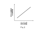
- the controller 6 stores the relationship between the target opening degree of the first pressure control valve 42 and the fuel consumption amount Qe of the engine 11 in advance as a table as shown in FIG. There is. Normally, the target opening degree of the first pressure adjustment valve 42 increases as the fuel consumption amount Qe of the engine 11 increases.
- control device 6 may determine the fuel consumption amount Qe of the engine 11 based on the operation amount of the telegraph lever operated by the operator.
- the control device 6 is divided into an engine control device that controls the engine 11 and a fuel supply control device that controls the pump 32 and various valves, the fuel supply control device is calculated by the engine control device.
- the fuel consumption amount Qe of the engine 11 may be determined based on the value related to the fuel injection amount.
- the control device 6 controls the pump 32 such that the opening degree of the first pressure adjusting valve 42 becomes the target opening degree corresponding to the actual fuel consumption amount Qe of the engine 11. That is, when the actual opening degree of the first pressure adjusting valve 42 is smaller than the target opening degree, the rotation of the pump 32 is performed in order to increase the fuel supply pressure to increase the opening degree of the first pressure adjusting valve 42. The number is increased. On the contrary, when the actual opening degree of the first pressure adjustment valve 42 is larger than the target opening degree, the fuel supply pressure is decreased to reduce the opening degree of the first pressure adjustment valve 42. The rotational speed is reduced.
- the target pressure of the first pressure adjustment valve 42 is increased.
- the rotational speed of the pump 32 is increased in order to raise the actual opening degree 42 to the target opening degree.
- the target opening degree of the first pressure adjustment valve 42 decreases, so the control device 6 performs the first pressure adjustment.
- the rotational speed of the pump 32 is reduced to reduce the actual opening degree of the valve 42 to the target opening degree.
- the controller 6 keeps the flow control valve 52 fully closed unless the number of revolutions of the pump 32 becomes the minimum number of revolutions.
- the minimum number of revolutions of the pump 32 may be a fixed value, but is changed according to, for example, the pressure of the air layer in the service tank 22 (the pressure of the air layer in the service tank 22 becomes higher It is desirable to lower the minimum speed).
- the control device 6 determines that the opening degree of the first pressure adjustment valve 42 is the actual value of the engine 11.
- One of the flow control valves 52 and 54 is controlled so as to achieve the target opening corresponding to the fuel consumption amount Qe. That is, when the actual opening degree of the first pressure adjustment valve 42 is smaller than the target opening degree, the flow control valve 52 is used to increase the fuel supply pressure to increase the opening degree of the first pressure adjustment valve 42. , 54 is reduced.
- the flow control valve The opening degree of one of 52 and 54 is increased.
- not only the opening degree of the first pressure control valve 42 but also the rotational speed of the pump 32 can be adjusted based on the first pressure gauge 71, so the pump 32 and the pump 32 and The first pressure control valve 42 can be stably controlled.
- first bypass line 51 and the second bypass line 53 are omitted and the rotational speed of the pump 32 becomes the minimum rotational speed
- a large amount of LPG may be allowed to pass through the engine 11.
- at least one of the first bypass line 51 and the second bypass line 53 is provided, and is provided in the first bypass line 51 or the second bypass line 53 when the number of revolutions of the pump 32 becomes the minimum number of revolutions. If the flow control valve (52 or 54) is opened, the supply flow rate of LPG to the engine 11 is increased by a fixed ratio more than the fuel consumption Qe of the engine 11 even when the number of revolutions of the pump 32 becomes the minimum number of revolutions. be able to.
- LPG passing through the engine 11 may be temporarily increased when the rotational speed of the pump 32 becomes the minimum rotational speed.
- the LPG returned to the service tank 22 through the second bypass line 53 receives heat from the pump 32. Therefore, as described above, if the LPG passing through the engine 11 is temporarily increased when the rotational speed of the pump 32 reaches the minimum rotational speed, the amount returned to the service tank 22 through the second bypass line 53 is On the other hand, since the LPG passing through the engine 11 is cooled by the cooler 44, the rise of the temperature of the LPG in the service tank 22 can be suppressed.
- the control device 6 increases the target opening degree of the first pressure adjustment valve 42.
- the target opening degree of the first pressure adjusting valve 42 does not always need to increase as the fuel consumption amount Qe of the engine 11 increases as shown in FIG. 2.
- the fuel tank 2 was comprised with the storage tank 21 and the service tank 22, the storage tank 21 may be abbreviate
- the fuel tank 2 can be divided into the storage tank 21 for LPG introduction, and the service tank 22 for LPG circulation.
- the fuel tank 2 does not necessarily have to be a pressure vessel, and may have a pressure resistance substantially equal to the atmospheric pressure. In this case, means for maintaining the LPG in the fuel tank 2 at a low temperature is required. However, if it is necessary to make the fuel tank 2 a pressure vessel if LPG is stored so that the temperature of the LPG changes following the ambient temperature as in the above embodiment, the LPG in the fuel tank 2 Means for keeping the temperature low.
Landscapes
- Engineering & Computer Science (AREA)
- Mechanical Engineering (AREA)
- Chemical & Material Sciences (AREA)
- Combustion & Propulsion (AREA)
- General Engineering & Computer Science (AREA)
- Ocean & Marine Engineering (AREA)
- Chemical Kinetics & Catalysis (AREA)
- General Chemical & Material Sciences (AREA)
- Oil, Petroleum & Natural Gas (AREA)
- Output Control And Ontrol Of Special Type Engine (AREA)
Abstract
船舶は、LPGを貯留する燃料タンクと、LPGを燃料とする推進用エンジンと、燃料タンクからエンジンへLPGを供給する燃料供給ラインと、燃料供給ラインに設けられたポンプと、エンジンから燃料タンクへ未使用のLPGを回収する燃料回収ラインと、燃料回収ラインに設けられた圧力調整弁と、ポンプおよび圧力調整弁を制御する制御装置と、エンジンへ供給されるLPGの圧力を検出する圧力計と、を備え、制御装置には、圧力調整弁の目標開度とエンジンの燃料消費量との関係が予め格納されており、制御装置は、圧力計で検出される圧力が設定値となるように圧力調整弁を制御するとともに、圧力調整弁の開度がエンジンの実際の燃料消費量に対応する目標開度となるようにポンプを制御する。
Description
本発明は、LPGを燃料とする推進用エンジンを含む船舶に関する。
従来の船舶では、一般的に、推進用エンジンの燃料は重油などの燃料油かLNG(Liquefied Natural Gas)であった。近年では、推進用エンジンの燃料としてLPG(Liquefied Petroleum Gas)を用いることも提案されている。
例えば、特許文献1には、燃料タンクから推進用エンジンへLPGを液体のまま供給する船舶が開示されている。LPGを燃料として用いた場合には、燃料油と比べて硫黄酸化物対策が不要であるとともに二酸化炭素排出量が少ないというメリットがあり、LNGと比べて比重が大きいために燃料タンクを小型化できるというメリットがある。
LPGを燃料として用いる場合には、燃料タンクと推進用エンジンとを燃料供給ラインおよび燃料回収ラインにより接続し、燃料タンクとエンジンとの間でLPGを循環しながら必要量だけエンジンで使用することが考えられる。
ところで、上記のように燃料タンクとエンジンとの間でLPGを循環させる場合には、エンジンの燃料消費量よりも少しだけ多い燃料をエンジンへ供給することが望ましい。これを実現するには、LPGのエンジンへの供給流量(燃料供給ラインを通じてエンジンへ流入する流量)またはエンジンからの回収流量(燃料回収ラインを通じてエンジンから流出する流量)を流量計で検出し、検出された流量がエンジンの燃料消費量に応じた所定値となるように、燃料供給ラインに設けられたポンプを制御することが考えられる。
また、エンジンへの燃料供給圧力をエンジンの要求範囲内に保つためには、エンジンへ供給されるLPGの圧力を圧力計で検出し、検出された圧力が設定値となるように、燃料回収ラインに設けられた圧力調整弁を制御することが考えられる。
しかしながら、上述したようにポンプおよび圧力調整弁を制御した場合には、流量制御と圧力制御とが干渉するおそれがある。
そこで、本発明は、燃料供給ラインに設けられたポンプおよび燃料回収ラインに設けられた圧力調整弁を安定的に制御することができる船舶を提供することを目的とする。
前記課題を解決するために、本発明の発明者らは、ポンプの吐出流量をエンジンの燃料消費量よりも一定割合だけ多くする場合には、燃料回収ラインに設けられた圧力調整弁を通過するタンク返送流量もその一定割合となることから、ポンプの吐出流量をエンジンの燃料消費量よりも一定割合だけ多くするためのエンジンの燃料消費量に対する圧力調整弁の目標開度を予め定めることが可能であることを見出した。つまり、圧力調整弁が目標開度になるということは、ポンプの吐出流量がエンジンの燃料消費量よりも一定割合だけ多くなることを意味する。本発明は、このような観点から成されたものである。
すなわち、本発明の船舶は、LPGを貯留する燃料タンクと、LPGを燃料とする推進用エンジンと、前記燃料タンクから前記エンジンへLPGを供給する燃料供給ラインと、前記燃料供給ラインに設けられたポンプと、前記エンジンから前記燃料タンクへ未使用のLPGを回収する燃料回収ラインと、前記燃料回収ラインに設けられた圧力調整弁と、前記ポンプおよび前記圧力調整弁を制御する制御装置と、前記エンジンへ供給されるLPGの圧力を検出する圧力計と、を備え、前記制御装置には、前記圧力調整弁の目標開度と前記エンジンの燃料消費量との関係が予め格納されており、前記制御装置は、前記圧力計で検出される圧力が設定値となるように前記圧力調整弁を制御するとともに、前記圧力調整弁の開度が前記エンジンの実際の燃料消費量に対応する目標開度となるように前記ポンプを制御する、ことを特徴とする。
上記の構成によれば、圧力計に基づいて圧力調整弁の開度だけでなくポンプの回転数も調整することができるので、ポンプおよび圧力調整弁を安定的に制御することができる。
上記の船舶は、前記ポンプの下流側で前記燃料供給ラインから分岐して前記燃料回収ラインまたは前記燃料タンクへつながるバイパスラインと、前記バイパスラインに設けられた流量制御弁と、をさらに備え、前記制御装置は、前記ポンプの回転数が最低回転数となったときに、前記圧力調整弁の開度が前記エンジンの実際の燃料消費量に対応する目標開度となるように前記流量制御弁を制御してもよい。この構成によれば、ポンプの回転数が最低回転数となったときでもエンジンへのLPGの供給流量をエンジンの燃料消費量よりも一定割合だけ多くすることができる。
前記燃料タンクは、LPGの温度が大気温度に追従して変化するようにLPGを貯留してもよい。この構成によれば、燃料タンクを圧力容器とする必要があるものの燃料タンク内のLPGを低温に維持する手段を不要とすることができる。
本発明によれば、燃料供給ラインに設けられたポンプおよび燃料回収ラインに設けられた圧力調整弁を安定的に制御することができる。
図1に、本発明の一実施形態に係る船舶1を示す。この船舶1は、LPGを燃料とする推進用エンジン11と、LPGを貯留する燃料タンク2を含む。LPGは、主成分がプロパンであってもよいし(プロパンガス)、ブタンであってもよい(ブタンガス)。
本実施形態では、燃料タンク2が、比較的に大きな容積のストレージタンク21と、比較的に小さな容積のサービスタンク22とで構成されている。ストレージタンク21およびサービスタンク22は、共に耐圧力が大気圧よりも高い圧力容器である。ストレージタンク21とサービスタンク22とは、中継ライン26によって互いに接続されている。
ストレージタンク21内には、LPG供給源から燃料導入ライン23を通じてLPGが導入される。LPG供給源は、船舶1に搭載されるカーゴタンクであってもよいし、陸上のLPG供給設備またはLPG燃料供給船であってもよい。
本実施形態では、ストレージタンク21にLPGを低温に維持する手段(例えば、断熱材)が設けられておらず、ストレージタンク21内のLPGの温度は大気温度に追従して変化する。一方、LPG供給源から導入されるLPGは、LPGがプロパンガスである場合には約-42℃であることが多い。従って、燃料導入ライン23には、LPGを例えば-5℃から大気温度までの範囲内の温度に加熱する加熱器24が設けられている。ただし、LPG供給源である陸上のLPG供給設備やLPG燃料供給船に加熱器が装備されており、船舶1に受け渡されるLPGの温度が-5℃以上であれば、加熱器24は不要である。
ストレージタンク21内の気層の成分が気化したPGのみの場合は、ストレージタンク21内の気層の圧力はLPGの飽和蒸気圧力である。例えば、ストレージタンク21内の温度が25℃である場合は、ストレージタンク21内の気層の圧力(飽和蒸気圧力)はゲージ圧で約0.9MPaである。以下、圧力の表示は全てゲージ圧である。なお、LPGの飽和蒸気圧力は、50℃で約1.7MPaであるので、ストレージタンク21は例えば1.8MPaまで耐えられるように構成される。参考までに、LPGの飽和蒸気圧力は、0℃で約0.4MPaである。
ストレージタンク21の内部にはポンプ25が設置されている。ポンプ25の数は1つであっても複数であってもよい。上述した中継ライン26の上流端は、ポンプ25へつながっている。また、中継ライン26の下流端は、サービスタンク22内で開口している。そして、ポンプ25により、中継ライン26を通じてストレージタンク21からサービスタンク22へLPGが供給される。ただし、ポンプ25はストレージタンク21の外で中継ライン26の途中に設けられてもよい。
ストレージタンク21と同様に、サービスタンク22にはLPGを低温に維持する手段が設けられておらず、サービスタンク22内のLPGの温度は大気温度に追従して変化する。サービスタンク22内の気層の成分が気化したPGのみの場合は、サービスタンク22内の気層の圧力はLPGの飽和蒸気圧力である。
後述するようなエンジン11とサービスタンク22との間でのLPGの循環時は、サービスタンク22内のLPGの温度は大気温度よりも高くてもよい。例えば、サービスタンク22内のLPGの温度が60℃である場合は、サービスタンク22内の気層の圧力(飽和蒸気圧力)は約2.1MPaである。なお、サービスタンク22は例えば2.2MPaまで耐えられるように構成される。
サービスタンク22は、燃料供給ライン31および燃料回収ライン41により推進用エンジン11と接続されている。つまり、燃料供給ライン31を通じてサービスタンク22からエンジン11へLPGが供給され、燃料回収ライン41を通じてエンジン11からサービスタンク22へ未使用のLPGが回収される。換言すれば、サービスタンク22とエンジン11との間で、燃料供給ライン31および燃料回収ライン41を通じてLPGが循環する。
燃料供給ライン31の上流端は、サービスタンク22の下部へつながっている。燃料回収ライン41の下流端は、サービスタンク22内で開口している。
エンジン11は、例えば、ディーゼルサイクルまたはオットーサイクルのレシプロエンジンである。図示は省略するが、エンジン11は、燃料供給ライン31の下流端と燃料回収ライン41の上流端とを接続する主流路と、主流路に互いに並列に接続された複数の燃料噴射弁を含む。
燃料供給ライン31には、上流側から順に、ポンプ32、加熱器33および遮断弁34が設けられている。加熱器33は、LPGをエンジン11の要求温度(例えば、45℃)まで加熱する。
上述した中継ライン26には、ストレージタンク21からサービスタンク22へ供給されるLPGを加熱する加熱器27が設けられている。エンジン11の稼働中は、エンジン11の燃料消費量Qeに相当する量のLPGがストレージタンク21からサービスタンク22へ供給される。加熱器27は、加熱器33だけではLPGをエンジン11の要求温度まで加熱することが困難な場合に使用される。なお、加熱器27は省略されてもよい。
燃料回収ライン41には、上流側から順に、第1圧力調整弁42(本発明の圧力調整弁に相当)、遮断弁43、冷却器44および第2圧力調整弁45が設けられている。冷却器44は、LPGを所定の温度(例えば、40℃)まで冷却する。なお、冷却器44は省略されてもよい。
本実施形態では、燃料供給ライン31と燃料回収ライン41とが第1バイパスライン51により接続されている。第1バイパスライン51は、加熱器33と遮断弁34の間で燃料供給ライン31から分岐し、遮断弁43と冷却器44の間で燃料回収ライン41へつながっている。第1バイパスライン51には、流量制御弁52が設けられている。
さらに、本実施形態では、第2バイパスライン53も採用されている。第2バイパスライン53は、ポンプ32と加熱器33の間で燃料供給ライン31から分岐し、サービスタンク22へつながっている。第2バイパスライン53には、流量制御弁54が設けられている。ただし、第1バイパスライン51と第2バイパスライン53のどちらか一方は省略されてもよい。
上述したポンプ32、遮断弁34,43、圧力調整弁42,45および流量制御弁52,54は、制御装置6により制御される。ただし、図1では、図面の簡略化のために一部の信号線のみを描いている。制御装置6は、例えば、ROMやRAMなどのメモリとCPUを有するコンピュータであり、ROMに記憶されたプログラムがCPUにより実行される。制御装置6は、単一の機器であってもよいし、複数の機器(例えば、エンジン制御装置と燃料供給制御装置)に分割されてもよい。
遮断弁34,43に関しては、制御装置6は、エンジン11の停止中は遮断弁34,43を閉じ、エンジン11のスタンバイ運転中及び稼動中に遮断弁34,43を開く。エンジン11の停止中は、遮断弁34,43の間の流路(燃料供給ライン31の下流側部分、エンジン11の主流路および燃料回収ライン41の上流側部分)が不活性ガスでパージされる。
制御装置6は、第1圧力計71(本発明の圧力計に相当)および第2圧力計72と電気的に接続されている。第1圧力計71はポンプ32、流量制御弁52,54および第1圧力調整弁42の制御に使用され、第2圧力計72は第2圧力調整弁45の制御に使用される。以下では、説明の便宜上、第2圧力調整弁45に基づく制御から説明する。
第2圧力計72は、第1圧力調整弁42と第2圧力調整弁45の間で燃料回収ライン41に設けられており、第1圧力調整弁42で減圧された後のLPGの圧力を検出する。本実施形態では、第2圧力計72が遮断弁43と冷却器44の間に位置しているが、遮断弁43の上流側または冷却器44の下流側に位置してもよい。
LPGの温度はLPGがエンジン11を通過することによって少し高くなる(例えば、55℃)。従って、第1圧力調整弁42で減圧されたLPGが気化することを防止するために、制御装置6は、第2圧力計72で検出される圧力が、想定される最大温度における飽和蒸気圧力よりも高い設定値(例えば、2.0MPa)となるように第2圧力調整弁45を制御する。
第1圧力計71は、ポンプ32の下流側で燃料供給ライン31に設けられており、エンジン11へ供給されるLPGの圧力を検出する。本実施形態では、第1圧力計71が遮断弁34の下流側に位置しているが、遮断弁34と加熱器33の間または加熱器33の上流側に位置してもよい。
第1圧力調整弁42に関しては、制御装置6は、第1圧力計71で検出される圧力がエンジン11の要求範囲内の設定値(例えば、エンジン11がディーゼルサイクルの場合、5.0~6.0MPa)となるように第1圧力調整弁42を制御する。
ポンプ32および流量制御弁52に関しては、制御装置6には、第1圧力調整弁42の目標開度とエンジン11の燃料消費量Qeとの関係が図2に示すようなテーブルとして予め格納されている。第1圧力調整弁42の目標開度は、通常は、エンジン11の燃料消費量Qeが大きくなるほど大きくなる。
例えば、制御装置6は、エンジン11の燃料消費量Qeを、操船者により操作されるテレグラフレバーの操作量に基づいて決定してもよい。あるいは、制御装置6がエンジン11を制御するエンジン制御装置と、ポンプ32および各種の弁を制御する燃料供給制御装置とに分割される場合は、燃料供給制御装置がエンジン制御装置にて算出された燃料噴射量に関する値に基づいてエンジン11の燃料消費量Qeを決定してもよい。
そして、制御装置6は、第1圧力調整弁42の開度がエンジン11の実際の燃料消費量Qeに対応する目標開度となるようにポンプ32を制御する。つまり、第1圧力調整弁42の実際の開度が目標開度よりも小さい場合には、燃料供給圧を上昇させて第1圧力調整弁42の開度を大きくするために、ポンプ32の回転数が増加される。逆に、第1圧力調整弁42の実際の開度が目標開度よりも大きい場合には、燃料供給圧を低下させて第1圧力調整弁42の開度を小さくするために、ポンプ32の回転数が低減される。
例えば、エンジン11の負荷が上昇してエンジン11の燃料消費量Qeが増加した場合には、第1圧力調整弁42の目標開度が上昇するために、制御装置6は、第1圧力調整弁42の実際の開度を目標開度まで上昇させるべくポンプ32の回転数を増加させる。逆に、エンジン11の負荷が低下してエンジン11の燃料消費量Qeが減少した場合には、第1圧力調整弁42の目標開度が低下するために、制御装置6は、第1圧力調整弁42の実際の開度を目標開度まで低下させるべくポンプ32の回転数を減少させる。
なお、制御装置6は、ポンプ32の回転数が最低回転数とならない限り、流量制御弁52を全閉に維持する。ポンプ32の最低回転数は、固定値であってもよいが、例えば、サービスタンク22内の気層の圧力に応じて変更される(サービスタンク22内の気層の圧力が高くなるほどポンプ32の最低回転数が低くされる)ことが望ましい。
第1圧力調整弁42の目標開度に基づく制御の結果、ポンプ32の回転数が最低回転数となったときには、制御装置6は、第1圧力調整弁42の開度がエンジン11の実際の燃料消費量Qeに対応する目標開度となるように流量制御弁52,54のどちらか一方を制御する。つまり、第1圧力調整弁42の実際の開度が目標開度よりも小さい場合には、燃料供給圧を上昇させて第1圧力調整弁42の開度を大きくするために、流量制御弁52,54のどちらか一方の開度が低減される。逆に、第1圧力調整弁42の実際の開度が目標開度よりも大きい場合には、燃料供給圧を低下させて第1圧力調整弁42の開度を小さくするために、流量制御弁52,54のどちらか一方の開度が増加される。
以上説明したように、本実施形態の船舶1では、第1圧力計71に基づいて第1圧力調整弁42の開度だけでなくポンプ32の回転数も調整することができるので、ポンプ32および第1圧力調整弁42を安定的に制御することができる。
(変形例)
本発明は上述した実施形態に限定されるものではなく、本発明の要旨を逸脱しない範囲で種々の変形が可能である。
本発明は上述した実施形態に限定されるものではなく、本発明の要旨を逸脱しない範囲で種々の変形が可能である。
例えば、第1バイパスライン51および第2バイパスライン53の双方が省略され、ポンプ32の回転数が最低回転数となったときはエンジン11を多量のLPGが通過することを許容してもよい。ただし、第1バイパスライン51および第2バイパスライン53の少なくとも一方が設けられており、ポンプ32の回転数が最低回転数となったときに第1バイパスライン51または第2バイパスライン53に設けられた流量制御弁(52または54)を開けば、ポンプ32の回転数が最低回転数となったときでもエンジン11へのLPGの供給流量をエンジン11の燃料消費量Qeよりも一定割合だけ多くすることができる。
あるいは、第2バイパスライン53が設けられた場合には、ポンプ32の回転数が最低回転数となったときにエンジン11を通過するLPGが一時的に増加されてもよい。第2バイパスライン53を通じてサービスタンク22へ返送されるLPGはポンプ32で熱を受けている。従って、前述したようにポンプ32の回転数が最低回転数となったときにエンジン11を通過するLPGが一時的に増加されれば、第2バイパスライン53を通じたサービスタンク22への返送量が減少する一方、エンジン11を通過するLPGは冷却器44で冷却されるので、サービスタンク22内のLPGの温度の上昇を抑制することができる。具体的には、ポンプ32の回転数が最低回転数となったときに、制御装置6が第1圧力調整弁42の目標開度を増加させる。このように、第1圧力調整弁42の目標開度は、常に図2に示すようにエンジン11の燃料消費量Qeが大きくなるほど大きくなる必要はない。
また、前記実施形態では、燃料タンク2がストレージタンク21とサービスタンク22で構成されていたが、ストレージタンク21が省略され、燃料タンク2がサービスタンク22のみで構成されてもよい。すなわち、サービスタンク22内にLPG供給源から直接的にLPGが導入されてもよい。しかし、前記実施形態のような構成であれば、燃料タンク2をLPG導入用のストレージタンク21とLPG循環用のサービスタンク22とに分けることができる。
また、燃料タンク2は、必ずしも圧力容器である必要はなく、耐圧力が大気圧と同程度のタンクであってもよい。この場合、燃料タンク2内のLPGを低温に維持する手段が必要である。ただし、前記実施形態のように燃料タンク2がLPGの温度が大気温度に追従して変化するようにLPGを貯留すれば、燃料タンク2を圧力容器とする必要があるものの燃料タンク2内のLPGを低温に維持する手段を不要とすることができる。
1 船舶
11 エンジン
2 燃料タンク
31 燃料供給ライン
32 ポンプ
41 燃料回収ライン
43,45 圧力調整弁
51 バイパスライン
52 流量制御弁
6 制御装置
71~73 圧力計
11 エンジン
2 燃料タンク
31 燃料供給ライン
32 ポンプ
41 燃料回収ライン
43,45 圧力調整弁
51 バイパスライン
52 流量制御弁
6 制御装置
71~73 圧力計
Claims (3)
- LPGを貯留する燃料タンクと、
LPGを燃料とする推進用エンジンと、
前記燃料タンクから前記エンジンへLPGを供給する燃料供給ラインと、
前記燃料供給ラインに設けられたポンプと、
前記エンジンから前記燃料タンクへ未使用のLPGを回収する燃料回収ラインと、
前記燃料回収ラインに設けられた圧力調整弁と、
前記ポンプおよび前記圧力調整弁を制御する制御装置と、
前記エンジンへ供給されるLPGの圧力を検出する圧力計と、を備え、
前記制御装置には、前記圧力調整弁の目標開度と前記エンジンの燃料消費量との関係が予め格納されており、
前記制御装置は、前記圧力計で検出される圧力が設定値となるように前記圧力調整弁を制御するとともに、前記圧力調整弁の開度が前記エンジンの実際の燃料消費量に対応する目標開度となるように前記ポンプを制御する、船舶。 - 前記ポンプの下流側で前記燃料供給ラインから分岐して前記燃料回収ラインまたは前記燃料タンクへつながるバイパスラインと、
前記バイパスラインに設けられた流量制御弁と、をさらに備え、
前記制御装置は、前記ポンプの回転数が最低回転数となったときに、前記圧力調整弁の開度が前記エンジンの実際の燃料消費量に対応する目標開度となるように前記流量制御弁を制御する、請求項1に記載の船舶。 - 前記燃料タンクは、LPGの温度が大気温度に追従して変化するようにLPGを貯留する、請求項1または2に記載の船舶。
Priority Applications (3)
| Application Number | Priority Date | Filing Date | Title |
|---|---|---|---|
| CN201880054826.2A CN110944907B (zh) | 2017-09-08 | 2018-08-31 | 船舶 |
| SG11202001976VA SG11202001976VA (en) | 2017-09-08 | 2018-08-31 | Ship |
| KR1020207009588A KR102303751B1 (ko) | 2017-09-08 | 2018-08-31 | 선박 |
Applications Claiming Priority (2)
| Application Number | Priority Date | Filing Date | Title |
|---|---|---|---|
| JP2017173006A JP6959806B2 (ja) | 2017-09-08 | 2017-09-08 | 船舶 |
| JP2017-173006 | 2017-09-08 |
Publications (1)
| Publication Number | Publication Date |
|---|---|
| WO2019049790A1 true WO2019049790A1 (ja) | 2019-03-14 |
Family
ID=65633947
Family Applications (1)
| Application Number | Title | Priority Date | Filing Date |
|---|---|---|---|
| PCT/JP2018/032407 Ceased WO2019049790A1 (ja) | 2017-09-08 | 2018-08-31 | 船舶 |
Country Status (5)
| Country | Link |
|---|---|
| JP (1) | JP6959806B2 (ja) |
| KR (1) | KR102303751B1 (ja) |
| CN (1) | CN110944907B (ja) |
| SG (1) | SG11202001976VA (ja) |
| WO (1) | WO2019049790A1 (ja) |
Families Citing this family (3)
| Publication number | Priority date | Publication date | Assignee | Title |
|---|---|---|---|---|
| CN112400057B (zh) * | 2019-06-18 | 2022-05-03 | 日本邮船有限公司 | 储罐以及船舶 |
| KR102785268B1 (ko) * | 2020-09-03 | 2025-03-26 | 한화오션 주식회사 | 액화가스 운반선의 연료공급시스템 및 방법 |
| CN113090417B (zh) * | 2021-03-29 | 2022-07-22 | 招商局重工(深圳)有限公司 | 一种lpg气液分离罐以及燃料控制系统 |
Citations (4)
| Publication number | Priority date | Publication date | Assignee | Title |
|---|---|---|---|---|
| JP2005351189A (ja) * | 2004-06-11 | 2005-12-22 | Nikki Co Ltd | エンジンの気体lpg供給装置 |
| JP2007064201A (ja) * | 2005-08-30 | 2007-03-15 | Hyundai Motor Co Ltd | Lpiエンジンシステム |
| JP2014051965A (ja) * | 2012-09-06 | 2014-03-20 | Hyundai Motor Company Co Ltd | Lpg燃料ポンプ制御システムおよび方法、およびこれを利用したlpiエンジンの燃料供給システム |
| JP2016037935A (ja) * | 2014-08-08 | 2016-03-22 | 川崎重工業株式会社 | ガス供給システム及びそれを備える船舶 |
Family Cites Families (5)
| Publication number | Priority date | Publication date | Assignee | Title |
|---|---|---|---|---|
| KR20100095909A (ko) * | 2009-02-23 | 2010-09-01 | 르노삼성자동차 주식회사 | Lpli 차량의 연료장치 |
| KR101284804B1 (ko) * | 2011-03-11 | 2013-07-10 | (주)모토닉 | 직접분사 엘피아이 시스템 및 그의 제어방법 |
| KR101631176B1 (ko) | 2011-04-05 | 2016-06-17 | 현대중공업 주식회사 | 듀얼 연료시스템이 마련된 액화석유가스 운반선 |
| JP2014162306A (ja) * | 2013-02-22 | 2014-09-08 | Mitsubishi Heavy Ind Ltd | 天然ガス燃料蒸発器、天然ガス燃料供給装置、船舶、原動機への天然ガス燃料の供給方法 |
| JP6600248B2 (ja) * | 2015-12-18 | 2019-10-30 | 川崎重工業株式会社 | 船舶 |
-
2017
- 2017-09-08 JP JP2017173006A patent/JP6959806B2/ja active Active
-
2018
- 2018-08-31 SG SG11202001976VA patent/SG11202001976VA/en unknown
- 2018-08-31 KR KR1020207009588A patent/KR102303751B1/ko active Active
- 2018-08-31 WO PCT/JP2018/032407 patent/WO2019049790A1/ja not_active Ceased
- 2018-08-31 CN CN201880054826.2A patent/CN110944907B/zh active Active
Patent Citations (4)
| Publication number | Priority date | Publication date | Assignee | Title |
|---|---|---|---|---|
| JP2005351189A (ja) * | 2004-06-11 | 2005-12-22 | Nikki Co Ltd | エンジンの気体lpg供給装置 |
| JP2007064201A (ja) * | 2005-08-30 | 2007-03-15 | Hyundai Motor Co Ltd | Lpiエンジンシステム |
| JP2014051965A (ja) * | 2012-09-06 | 2014-03-20 | Hyundai Motor Company Co Ltd | Lpg燃料ポンプ制御システムおよび方法、およびこれを利用したlpiエンジンの燃料供給システム |
| JP2016037935A (ja) * | 2014-08-08 | 2016-03-22 | 川崎重工業株式会社 | ガス供給システム及びそれを備える船舶 |
Also Published As
| Publication number | Publication date |
|---|---|
| JP2019048509A (ja) | 2019-03-28 |
| KR20200051695A (ko) | 2020-05-13 |
| JP6959806B2 (ja) | 2021-11-05 |
| SG11202001976VA (en) | 2020-04-29 |
| CN110944907A (zh) | 2020-03-31 |
| KR102303751B1 (ko) | 2021-09-23 |
| CN110944907B (zh) | 2022-04-08 |
Similar Documents
| Publication | Publication Date | Title |
|---|---|---|
| KR102330773B1 (ko) | 선박 | |
| JP6982439B2 (ja) | 船舶 | |
| US11441736B2 (en) | Multi-vessel fluid storage and delivery system | |
| JP6600247B2 (ja) | 船舶 | |
| JP6678077B2 (ja) | 船舶 | |
| JP6600248B2 (ja) | 船舶 | |
| JP6401544B2 (ja) | ガス供給システム及びそれを備える船舶 | |
| JP6959806B2 (ja) | 船舶 | |
| CN112638763B (zh) | 船舶 | |
| JP6959804B2 (ja) | 船舶およびlpg温度/圧力管理方法 | |
| JP2017110797A (ja) | 船舶 | |
| JP6959805B2 (ja) | 船舶 | |
| JP6757217B2 (ja) | 船舶 | |
| JP2018103954A (ja) | 船舶 | |
| WO2017078155A1 (ja) | 船舶 | |
| JP2018103955A (ja) | 船舶 | |
| JP6722074B2 (ja) | 船舶 | |
| KR102884340B1 (ko) | 선박의 연료공급시스템 |
Legal Events
| Date | Code | Title | Description |
|---|---|---|---|
| 121 | Ep: the epo has been informed by wipo that ep was designated in this application |
Ref document number: 18854404 Country of ref document: EP Kind code of ref document: A1 |
|
| NENP | Non-entry into the national phase |
Ref country code: DE |
|
| ENP | Entry into the national phase |
Ref document number: 20207009588 Country of ref document: KR Kind code of ref document: A |
|
| 122 | Ep: pct application non-entry in european phase |
Ref document number: 18854404 Country of ref document: EP Kind code of ref document: A1 |