WO2019049564A1 - 魚類の心臓の状態をモニタリングするシステム - Google Patents
魚類の心臓の状態をモニタリングするシステム Download PDFInfo
- Publication number
- WO2019049564A1 WO2019049564A1 PCT/JP2018/028869 JP2018028869W WO2019049564A1 WO 2019049564 A1 WO2019049564 A1 WO 2019049564A1 JP 2018028869 W JP2018028869 W JP 2018028869W WO 2019049564 A1 WO2019049564 A1 WO 2019049564A1
- Authority
- WO
- WIPO (PCT)
- Prior art keywords
- fish
- photoplethysmogram
- heart
- detectors
- container
- Prior art date
- Legal status (The legal status is an assumption and is not a legal conclusion. Google has not performed a legal analysis and makes no representation as to the accuracy of the status listed.)
- Ceased
Links
Images


Classifications
-
- A—HUMAN NECESSITIES
- A01—AGRICULTURE; FORESTRY; ANIMAL HUSBANDRY; HUNTING; TRAPPING; FISHING
- A01K—ANIMAL HUSBANDRY; AVICULTURE; APICULTURE; PISCICULTURE; FISHING; REARING OR BREEDING ANIMALS, NOT OTHERWISE PROVIDED FOR; NEW BREEDS OF ANIMALS
- A01K61/00—Culture of aquatic animals
- A01K61/10—Culture of aquatic animals of fish
- A01K61/13—Prevention or treatment of fish diseases
-
- A—HUMAN NECESSITIES
- A01—AGRICULTURE; FORESTRY; ANIMAL HUSBANDRY; HUNTING; TRAPPING; FISHING
- A01K—ANIMAL HUSBANDRY; AVICULTURE; APICULTURE; PISCICULTURE; FISHING; REARING OR BREEDING ANIMALS, NOT OTHERWISE PROVIDED FOR; NEW BREEDS OF ANIMALS
- A01K63/00—Receptacles for live fish, e.g. aquaria; Terraria
-
- A—HUMAN NECESSITIES
- A61—MEDICAL OR VETERINARY SCIENCE; HYGIENE
- A61B—DIAGNOSIS; SURGERY; IDENTIFICATION
- A61B5/00—Measuring for diagnostic purposes; Identification of persons
- A61B5/0033—Features or image-related aspects of imaging apparatus, e.g. for MRI, optical tomography or impedance tomography apparatus; Arrangements of imaging apparatus in a room
- A61B5/004—Features or image-related aspects of imaging apparatus, e.g. for MRI, optical tomography or impedance tomography apparatus; Arrangements of imaging apparatus in a room adapted for image acquisition of a particular organ or body part
- A61B5/0044—Features or image-related aspects of imaging apparatus, e.g. for MRI, optical tomography or impedance tomography apparatus; Arrangements of imaging apparatus in a room adapted for image acquisition of a particular organ or body part for the heart
-
- Y—GENERAL TAGGING OF NEW TECHNOLOGICAL DEVELOPMENTS; GENERAL TAGGING OF CROSS-SECTIONAL TECHNOLOGIES SPANNING OVER SEVERAL SECTIONS OF THE IPC; TECHNICAL SUBJECTS COVERED BY FORMER USPC CROSS-REFERENCE ART COLLECTIONS [XRACs] AND DIGESTS
- Y02—TECHNOLOGIES OR APPLICATIONS FOR MITIGATION OR ADAPTATION AGAINST CLIMATE CHANGE
- Y02A—TECHNOLOGIES FOR ADAPTATION TO CLIMATE CHANGE
- Y02A40/00—Adaptation technologies in agriculture, forestry, livestock or agroalimentary production
- Y02A40/80—Adaptation technologies in agriculture, forestry, livestock or agroalimentary production in fisheries management
- Y02A40/81—Aquaculture, e.g. of fish
Definitions
- the present invention relates to a system for monitoring the condition of the heart of a fish.
- Non-patent documents 1 and 3 there is a method of inserting an electrode probe into a fixed fish and acquiring an electrocardiogram (Non-patent documents 1 and 3).
- Patent Document 1 there is a method of measuring a photoelectric pulse wave in the vicinity of a heart of a fish under anesthesia in a fixed container using a transmission type probe (Patent Document 1).
- Patent Document 2 there is a method of analyzing the physiological function of the fish by photographing the heart of the fish using a container having a predetermined space for containing the target fish in water and analyzing the photographed image
- Patent Document 2 There is also known a method of performing chaos analysis on the stress state of the fish based on the information obtained by monitoring the state of the heart of the fish.
- Non-Patent Document 1 In order to monitor the physiological functions of fish in land aquaculture, it is important to monitor the condition of the heart of the target fish in a state equivalent to natural aquaculture.
- the method of Non-Patent Document 1 is an invasive method in that the target fish is fixed and the electrode probe is inserted into the fish, and there is a concern that the fish may be killed. Further, the method of Patent Document 1 has a problem in terms of the degree of freedom of the measurement probe position. Moreover, since it is essential to be limited to laboratory use and to suppress or stop the movement of fish by anesthesia, it can not be said that monitoring in a state equivalent to a natural aquaculture state.
- the container having a predetermined size limits the movement of the fish fin and the left and right movement of the body blocks the characteristic and vision of swimming forward, so this is also a natural aquaculture. It is difficult to say that monitoring is equivalent to the state.
- the present invention has been made in view of such circumstances, and an object thereof is to provide a system for monitoring the condition of the heart of a target fish in a state equivalent to a natural culture condition.
- the inventors of the present invention analyze a photoplethysmograph by arranging a plurality of detectors on the inner wall surface of the container and acquiring the photoplethysmogram from each of the detectors. By doing this, it has been found that it is possible to extract the part that most reflects the photoplethysmogram of the target fish heart region and to monitor the condition of the heart of the fish.
- the present invention is as follows.
- a container and a processing device are included, and the container is provided with a plurality of detectors on the inner wall surface of the container, and the fish can swim on the opposite side of the detector with respect to the fish in the container
- An acquisition unit that includes a space, and the processing device acquires the photoplethysmograms of a plurality of parts of the fish in a time series over a predetermined detection period under signal synchronization via a measurement device having the plurality of detectors;
- a system for monitoring the condition of the heart of a fish comprising an extraction unit for extracting a portion that most reflects the photoplethysmogram of the heart region of the fish from the photoplethysmograms of multiple sites acquired during the detection period.
- the velocity pulse wave is calculated from the acquired photoplethysmograms of a plurality of sites, and the portion that most reflects the photoplethysmogram of the heart site is extracted in the obtained photoplethysmograms of the plurality of sites.
- one cycle is between the minimum value and the next minimum value that arrives temporally, two or more maximum values exist in the velocity pulse wave in a period corresponding to the one cycle, and among them, the time
- the system according to [1] which is to extract a cycle in which the difference between the locally arriving maximal value and the temporally arriving maximal value is 0.5 V / s or more.
- a pseudo R-R interval is calculated from photoplethysmograms of a plurality of sites acquired in the detection period, and a portion most reflecting the photoplethysmogram of the heart region is extracted, the pseudo R-R interval
- the system according to [1] which is to extract a photoplethysmogram corresponding to a period in which the standard deviation of is less than or equal to 0.08.
- the plurality of detectors are present at equal intervals.
- the system according to any one of [1] to [4], wherein the fish is a flatfish or flatfish.
- the detector comprises an element for detecting light.
- Step of acquiring photoplethysmograms of a plurality of parts of fish in time series over a predetermined detection period under signal synchronization with a plurality of detectors, and photoplethysmograms of a plurality of parts acquired during the detection period A method of monitoring the condition of the heart of a fish, comprising the step of extracting a portion that most reflects the photoplethysmogram of the heart region of the fish.
- a plurality of detectors are provided on a wall surface in contact with a space where fish can swim, and predetermined detection of photoplethysmograms of a plurality of parts of the fish is performed under signal synchronization via a measuring device having the plurality of detectors
- a processing apparatus comprising: an acquisition unit for acquiring in time series over a period, and an extraction unit for extracting a portion that most reflects the photoplethysmogram of the heart region of the fish from the photoplethysmograms of a plurality of sites acquired during the detection period.
- FIG. 5 shows the position of the detector and light source relative to the fish of interest according to one embodiment of the present invention.
- FIG. 1 illustrates one embodiment of the system of the present invention. It is a flowchart which shows from detection of the photoplethysmogram from several site
- FIG. 2 shows a detector according to an embodiment of the present invention. It is the photoelectric pulse wave acquired by the Example of this invention.
- (B) a photoplethysmogram acquired from a location distant from the heart site Is a graph showing the pR-R interval calculated based on.
- the present invention includes a container and a processing device, wherein the container is provided with a plurality of detectors on the inner wall surface of the container, and the fish can swim on the opposite side of the detector with respect to the fish in the container.
- the system according to the invention comprises a container.
- the container is provided with a plurality of detectors on the inner wall surface of the container (including the bottom of the container), and includes a space in which the fish can swim on the opposite side of the detector as viewed from the fish in the container Therefore, if the fish can be stored in a state equivalent to a natural state of aquaculture, signals can be obtained from a plurality of parts of the fish over a predetermined period, and the photoplethysmogram can be obtained, the volume, the material, etc. are not particularly limited. For example, the water tank etc. which are used for land culture are mentioned.
- the acquisition unit does the following.
- the detector is not particularly limited as long as it can obtain a signal and obtain it as a photoplethysmogram through calculation processing, but it is preferable that the detector is configured of an element that detects light.
- information capable of generating a velocity plethysmogram for example, a dicrotic notch It is preferable that it is a detector which has the performance to such an extent that the photoplethysm wave which has appeared is acquired.
- Non-Patent Document 2 there is a reflection type photodetector in which a light source and a detector are disposed on the same plane, and fish is irradiated with light from a near-infrared light emitting diode as described in Non-Patent Document 2 , A detector that detects light reflected from the skin and backscattered light from the body with a PIN photodiode.
- Commercially available light emitting diodes include SLR938-CV (central emission wavelength 945 nm, Sanyo), and light detectors include PIN photodiode TPS703 (Toshiba) and S1336-18BQ (HAMAMATSU).
- a light emitting diode having a central emission wavelength of 945 nm it is preferable to use. This is because there is little absorption by fat and it is close to the isosbestic point. It is reported that the near infrared region is easily absorbed by fat and non-patent document 5 shows a peak of absorption around 940 nm.
- the arrangement area of the detectors is the inner wall surface of the container (including the bottom of the container), and may be only a specific area without interference from other detectors.
- the specific region includes, for example, a region where fish prefers to stagnate, such as a nest or a shade.
- a reflective photodetector is described as an example of a detector, but the detector in the present invention is not limited to this.
- the center-to-center distance between the light source and the detector can be appropriately set according to the relationship with the subcutaneous depth as the measurement point in the target fish.
- the light source and the detector are defined as "one set of light source-detector", it is possible to prevent the light from turning around and interfering with each other by providing a predetermined distance from the adjacent set.
- the interval can be appropriately adjusted by those skilled in the art.
- the size of the light receiving surface of the detector depends on the size of the target fish, but when the light receiving surface is large, the number of measurement points is smaller than that of the target fish, while the light receiving surface is smaller. In the case where many detectors are not provided, only a part of the target fish can be measured.
- the arrangement pattern is not particularly limited, but is preferably a regular pattern, and more preferably an equidistant pattern.
- the rows of the detectors 13 and the one direction are The rows of light sources 14 are arranged in rows, and the rows of detectors 13 are sandwiched between the rows of light sources 14 and the rows of other detectors 15, and so on. It is preferable to arrange it so as to be sandwiched between a row and another row of light sources (not shown), since the interference between the light source and the detector set is eliminated.
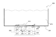
- the system 200 of the present invention includes a container 201, an acquisition unit 202, an extraction unit 203 (including a calculation unit), a detector 204, and a light source 205.
- the acquisition unit 202 may include, for example, a detector selection signal generation unit 206, a signal processing circuit 207, a detector selection circuit 208, an amplification circuit 209, a drive circuit 210, and a synchronization circuit 211, and can be appropriately configured.
- the synchronization circuit 211 generates a reference clock for switching the operation of each channel.
- the detector selection circuit 208 incorporating a plurality of multiplexers sequentially outputs the signal for each channel, and the extraction unit 203 sequentially determines the valid signal (mode 1).
- the detector selection circuit 208 operates so that the multiplexer outputs only the selected channel by the detector selection signal generation unit 206 incorporating the logic circuit, and only the effective signal is output for a predetermined period.
- Acquire (mode 2). In FIG. 2, fish (target fish) 212 and water 213 are also described.
- the predetermined detection period is sufficient to extract at least a portion that most reflects the photoplethysmogram of the heart region of the fish from a plurality of photoplethysmograms acquired in the detection period in the extraction unit described later. It is not limited if it is a period.
- a photoplethysmogram acquired from the vicinity of the heart shown by Ch1 (channel 1) one cycle (a cycle between a certain minimum value and the next minimum value arriving in time) ( It is sufficient if it is not less than a period during which D1) in FIG. 6 can be obtained, preferably 3 seconds or more, more preferably 6 seconds or more, and still more preferably 9 seconds or more.
- the upper limit of the detection period is not particularly limited, but is, for example, 10 seconds or less.
- a velocity pulse wave When a velocity pulse wave is used, one cycle between a certain minimum value and the next minimum value that arrives temporally in the same manner as described above in the corresponding photoplethysmogram (see FIGS. 7A and 7B). It may be at least a period during which D1 in B) can be obtained, preferably 3 seconds or more, more preferably 6 seconds or more, and still more preferably 9 seconds or more.
- the upper limit of the detection period is not particularly limited, but is, for example, 10 seconds or less.
- the detection period in which the standard deviation can be calculated in the pseudo R-R interval, preferably 60 seconds or more, more preferably 120 seconds or more, still more preferably It is 180 seconds or more.
- the upper limit of the detection period is not particularly limited, but is, for example, 600 seconds or less.
- a sampling frequency for acquiring a photoelectric pulse wave it is 1 kHz or more normally, Preferably it is 2 kHz or more, More preferably, it is 5 kHz or more.
- the upper limit is not particularly limited, but is, for example, 10 kHz or less. It is preferable that the detection period be a period during which the movement of the target fish is small or a stationary period, since analysis becomes easy.
- the fish is not particularly limited as long as it is taxonomic fish, but it is preferable that the body is a body capable of acquiring photoplethysmograms at multiple sites.
- the standard length (the length from the tip of the upper jaw to the caudal fin base) is preferably 0.8 cm or more, more preferably 3 cm or more, still more preferably 5 cm or more, while preferably 100 cm or less, more preferably It is 50 cm or less, more preferably 30 cm or less.
- the body height is preferably 1 mm or more, more preferably 3 mm or more, further preferably 5 mm or more, while preferably 3 cm or less, more preferably 2 cm or less, and still more preferably 1 cm or less.
- the body width is preferably 0.5 cm or more, more preferably 1 cm or more, still more preferably 3 cm or more, while preferably 30 cm or less, more preferably 25 cm or less, still more preferably 20 cm or less .
- the fish is preferably a fish classified into flatfish, more preferably flounder or flatfish.
- it is preferable to easily acquire a photoplethysmogram because a flatfish or flounder has a long period of resting in one place at the bottom in the container.
- the extractor does the following: As in the examples to be described later, the present inventors have found that the phase of the photoplethysmogram is shifted between the vicinity of the heart of the target fish and the position away from the heart. This is presumed to be due to the difference in the propagation time of vibration when the heart contracts and the surrounding organs are filled with blood. Furthermore, since gills operate at the timing of blood discharge from the heart, it is presumed that the muscle vibrations are also transmitted. Further, to explain with reference to FIG. 6, in the photoplethysmogram obtained from the vicinity of the heart shown by Ch 1 (channel 1), one cycle (a cycle between a certain minimum value and the next minimum value arriving in time) In the case of D1) in FIG.
- FIG. 7A shows a photoplethysmogram acquired from Ch1 (channel 1), which is the same as the photoplethysmogram acquired from Ch1 (channel 1) in FIG.
- FIG. 7 (B) is one in which the photoplethysmogram is calculated as a velocity plethysmogram.
- two or more local maximum values of the velocity pulse wave exist in one cycle indicated by D1, and among them, the local maximum value a1 that arrives first temporally and then the next one temporally The difference from the maximum value a2 is large.
- FIG. 7A shows a photoplethysmogram acquired from Ch1 (channel 1), which is the same as the photoplethysmogram acquired from Ch1 (channel 1) in FIG.
- FIG. 7 (B) is one in which the photoplethysmogram is calculated as a velocity plethysmogram.
- FIG. 7C shows a photoplethysmogram acquired from Ch2 (channel 2), which is the same as the photoplethysmogram acquired from Ch2 (channel 2) in FIG.
- FIG. 7 (D) is one in which the photoplethysmogram is calculated as a velocity plethysmogram.
- two or more local maximum values of the velocity pulse wave exist in one cycle indicated by D2, and among them, the local maximum value a2 that arrives first temporally and then temporally There is almost no difference between the incoming local maximum values b2.
- the portion that most reflects the photoplethysmogram of the heart region using the velocity plethysmogram there are two or more local maxima of the velocity plethysmogram, and among them, the maximum value that arrives first in time It is preferable to extract a cycle having a large difference with respect to the temporally arriving maximum value, and the difference is preferably 0.5 V / s or more, more preferably 1.0 V / s or more, More preferably, it is 2.1 V / s or more.
- the pulse wave peak interval from the photoplethysmogram (herein, it is defined as “pseudo RR interval", and the English translation Pseudo RR Interval may be abbreviated as "pRR interval”. It is also preferable to calculate the portion that most reflects the photoplethysmogram of the heart region of fish based on this. Generally, in the case of electrocardiogram measurement, RR interval is used as the interval of R waves, and in the case of photoplethysmogram, aa interval is used, but in the present invention, even if the acceleration pulse wave is determined to be near the heart.
- the standard deviation of the pRR interval in a predetermined period can be used as an index, and the standard deviation is ⁇ d shown in FIG. 8 when described using the embodiment.
- the lower limit is usually larger than 0 seconds.
- a photoplethysmogram corresponding to a period in which the standard deviation falls within the above range in the pRR interval can be extracted as a portion that most reflects the photoplethysmogram of the heart region of the fish.
- the processing apparatus includes a plurality of detectors on a wall surface in contact with a space in which fish can swim, and the photoelectric pulse waves of a plurality of parts of the fish are determined under signal synchronization via a measuring device having the plurality of detectors.
- the acquisition unit acquiring in chronological order over the detection period of the blood vessel, and the extraction unit extracting the portion that most reflects the photoplethysmogram of the heart region of the fish from the photoplethysmograms of the multiple sites acquired during the detection period It may be When the processing apparatus is used in the system, the wall may be an inner wall of the container.
- the wall surface is a surface such as a substrate
- the treatment device is allowed to stand in a container containing water, preferably, the inner wall surface of the container containing water.
- the like, and the like There are no particular limitations on the shape, size, and material of the substrate and the like as long as a plurality of detectors are provided and the acquisition unit and the extraction unit can exhibit their functions.
- the stress state of the fish may be analyzed, for example, as reported in Non-Patent Document 2.
- the photoplethysmogram extracted by the system according to the present invention is synthesized into a temporally continuous photoplethysmogram. You may go from.
- Such measures include, for example, optimization of water quality (eg, water temperature, pH, osmotic pressure, salt concentration, oxygen concentration, carbon dioxide concentration, ammonia concentration, nitrogen concentration, hardness (calcium salt, magnesium salt etc.), etc.)
- optimization of light intensity, food, feeding, number of fish, density of fish, frequency of fresh water, etc. examination of food preference, sterilization, detection and elimination of diseased fish, etc. may be mentioned. Any of these measures can follow the usual law.
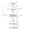
- FIG. 3 is a flow showing a detection start S101 to a stress state determination S106.
- the extraction unit 203 performs from the detection start S101 to the stress state analysis S105.
- a computer etc. are mentioned as the extraction part 203.
- the determination S106 of the stress state may be performed by a person or by the extraction unit 203.
- step S103 determines whether the determination in step S103 is negative, the detection is performed again. On the other hand, if S103 is affirmed, the process proceeds to S104, and the photoplethysmogram of the heart portion of the fish is obtained from the obtained photoplethysmograms according to each aspect described in the “extraction section” column. Extract the part that reflects most.
- S104 the process proceeds to S105, where the stress state of the fish is analyzed as reported in, for example, non-patent document 2, and when the analysis is completed, the process proceeds to S106 and the fish is analyzed based on the analysis result. Determine stress conditions.
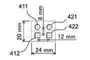
- FIG. 5 shows the dimensions and the like of channel 1 and channel 2.
- a signal was acquired for 6 minutes through a sampling frequency of 1 kHz and a low pass filter of 5 Hz with a data logger (GL 900, GRAPHTEC) via a DC servo amplifier.
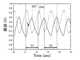
- FIG. 6 shows photoplethysmogram data acquired from channel 1 (Ch1) and channel 2 (Ch2).
- the photoplethysmogram acquired from the channel 1 has a point a where the slope is significantly reduced when the photoplethysmogram increases within one cycle indicated by D1 in FIG.
- FIG. 7A shows a photoplethysmogram acquired from the channel 1, which is the same as the photoplethysmogram of the channel 1 in FIG.
- FIG. 7 (B) is one in which the photoplethysmogram is calculated as a velocity plethysmogram.
- FIG. 7B it was confirmed that two or more local maximum values of the velocity pulse wave exist in one cycle indicated by D1.
- FIG. 7C shows a photoplethysmogram acquired from the channel 2, which is the same as the photoplethysmogram of the channel 2 in FIG.
- FIG. 7 (D) is one in which the photoplethysmogram is calculated as a velocity plethysmogram.
- Example 2 pRR interval analysis 8 (A) and 8 (B) show the results obtained by using Akima splines in Origin based on the photoplethysmograms obtained from channel 1 (Ch1) and channel 2 (Ch2) of Example 1, respectively. It is a pR-R interval obtained by sampling 0 seconds to 120 seconds in seconds.
- the pR-R interval based on the photoplethysmogram acquired from channel 1 (Ch1) had an average of 1.108 seconds, 54.2 bpm in terms of heart rate, and a standard deviation of 0.024 seconds.
- the average is 1.111 seconds, 54.0 bpm in terms of heart rate, and the standard deviation is 0.096 seconds.
Landscapes
- Life Sciences & Earth Sciences (AREA)
- Environmental Sciences (AREA)
- Health & Medical Sciences (AREA)
- Marine Sciences & Fisheries (AREA)
- Animal Husbandry (AREA)
- Biodiversity & Conservation Biology (AREA)
- Radiology & Medical Imaging (AREA)
- Zoology (AREA)
- Nuclear Medicine, Radiotherapy & Molecular Imaging (AREA)
- Pathology (AREA)
- Surgery (AREA)
- Biophysics (AREA)
- Cardiology (AREA)
- Engineering & Computer Science (AREA)
- Biomedical Technology (AREA)
- Heart & Thoracic Surgery (AREA)
- Medical Informatics (AREA)
- Molecular Biology (AREA)
- Physics & Mathematics (AREA)
- Animal Behavior & Ethology (AREA)
- General Health & Medical Sciences (AREA)
- Public Health (AREA)
- Veterinary Medicine (AREA)
- Farming Of Fish And Shellfish (AREA)
- Measuring Pulse, Heart Rate, Blood Pressure Or Blood Flow (AREA)
- Electrotherapy Devices (AREA)
- Measuring And Recording Apparatus For Diagnosis (AREA)
Abstract
本発明は、自然な養殖状態と同等の状態で対象とする魚類の心臓の状態をモニタリングするシステムの提供を課題とする。該課題を、容器と処理装置とを含み、該容器は、該容器の内壁面に複数の検出器が備えられ、該容器内の魚類からみて該検出器側と逆側に該魚類が遊泳可能な空間を含み、該処理装置は、該複数の検出器を有する測定装置を介して、信号同期の下、魚類の複数部位の光電脈波を所定の検出期間にわたって時系列で取得する取得部、及び該検出期間に取得された複数部位の光電脈波から、該魚類の心臓部位の光電脈波を最も反映する部分を抽出する抽出部を備える、魚類の心臓の状態をモニタリングするシステムで解決する。
Description
本発明は、魚類の心臓の状態をモニタリングするシステムに関する。
魚類の海面養殖では、養殖魚の残餌や糞便による養殖場の底質汚染や富栄養化などによる環境悪化が年々進んでいる。その結果、魚病発生や赤潮などが近年頻発し、産業的に大きな被害を出し続けている。
一方、陸上養殖では飼育環境を全て制御でき、安全・安心な養殖魚の生産ができるというメリットはあるが、完全閉鎖系の為に養殖魚に対して持続的にストレスが付与されていることが容易に予測され、また一度感染症などの病気が発生すると被害は大きくなる傾向にある。
このような陸上養殖の問題点を解決するためには、魚類のストレス状態、延いては健康状態をリアルタイムに把握し、如何に持続的に健康状態を維持しながら感染症などの病害発生を阻止し、飼料転換効率などを向上させて行くかが強く求められる。
そういったことから、生きたままの状態で魚類の生体モニタリング技術は必須であり、現在までにいくつか研究されている。陸上養殖における魚類の生理機能を監視するための方法として、例えば、水槽から魚を定期的にサンプリングし、該魚の心臓の状態をモニタリングする方法がある。
一方、陸上養殖では飼育環境を全て制御でき、安全・安心な養殖魚の生産ができるというメリットはあるが、完全閉鎖系の為に養殖魚に対して持続的にストレスが付与されていることが容易に予測され、また一度感染症などの病気が発生すると被害は大きくなる傾向にある。
このような陸上養殖の問題点を解決するためには、魚類のストレス状態、延いては健康状態をリアルタイムに把握し、如何に持続的に健康状態を維持しながら感染症などの病害発生を阻止し、飼料転換効率などを向上させて行くかが強く求められる。
そういったことから、生きたままの状態で魚類の生体モニタリング技術は必須であり、現在までにいくつか研究されている。陸上養殖における魚類の生理機能を監視するための方法として、例えば、水槽から魚を定期的にサンプリングし、該魚の心臓の状態をモニタリングする方法がある。
該モニタリングの方法としては、例えば、固定した魚に電極プローブを挿入して心電図を取得する方法がある(非特許文献1、3)。また、固定容器内で麻酔下にある魚の心臓付近の光電脈波を、透過型プローブを用いて計測する方法がある(特許文献1)。さらに、対象とする魚を水中で収容する所定の空間を有する容器を用いて該魚の心臓を撮影し、撮影された画像を解析するなどして、該魚の生理機能を解析する方法がある(特許文献2)。また、魚の心臓の状態をモニタリングして得られた情報に基づいて、該魚のストレス状態をカオス解析する方法も知られている(非特許文献2)。
小島隆人、魚類の心電図導出技術とその応用、日本水産学会誌 79 3 (2013), pp.319-322
井上裕基、宮田剛、時間分解ヒストグラムパターンによるストレス-リラックス時系列遷移の可視化、第29回バイオメディカル・ファジィ・システム学会年次大会講演論文集、2016年11月26日発行
藤田薫、渡部俊広、張秀梅、ヒラメの心拍数に及ぼす光環境と底質の影響、水産工学研究所技報 18 (1996), pp.233-238
小島隆人、根石裕大、吉崎康仁、添田秀男、最大エントロピー法を利用した魚類心拍変動の周波数分析、水産工学 38 2 (2001), pp.145-150
山内悟、蔦元淳司、水野俊博、ハンディー型近赤外測定器によるマアジおよびその干物の脂肪測定、日本食品科学工学会誌 53 7 (2006), pp.393-397
陸上養殖における魚類の生理機能を監視するためには、自然な養殖状態と同等の状態で対象とする魚の心臓の状態をモニタリングすることが重要である。
非特許文献1の方法では、対象とする魚を固定し、該魚に電極プローブを挿入する点で侵襲的な方法であり、魚を殺傷してしまうことも懸念される。また、特許文献1の方法では、計測プローブ位置の自由度の点で問題がある。また、ラボラトリーユースに限定される上、麻酔により魚の運動を抑制又は停止することが必須であるため、自然な養殖状態と同等な状態におけるモニタリングとは言い難い。さらに、特許文献2の方法では、所定の大きさを有する容器によって魚のヒレの動作が制限され、また、体の左右動作によって前へ泳いで進む特性と視覚が遮られるため、これも自然な養殖状態と同等な状態におけるモニタリングとは言い難い。
本発明はこのような状況に鑑みてなされたものであり、自然な養殖状態と同等の状態で対象とする魚類の心臓の状態をモニタリングするシステムの提供を課題とする。
非特許文献1の方法では、対象とする魚を固定し、該魚に電極プローブを挿入する点で侵襲的な方法であり、魚を殺傷してしまうことも懸念される。また、特許文献1の方法では、計測プローブ位置の自由度の点で問題がある。また、ラボラトリーユースに限定される上、麻酔により魚の運動を抑制又は停止することが必須であるため、自然な養殖状態と同等な状態におけるモニタリングとは言い難い。さらに、特許文献2の方法では、所定の大きさを有する容器によって魚のヒレの動作が制限され、また、体の左右動作によって前へ泳いで進む特性と視覚が遮られるため、これも自然な養殖状態と同等な状態におけるモニタリングとは言い難い。
本発明はこのような状況に鑑みてなされたものであり、自然な養殖状態と同等の状態で対象とする魚類の心臓の状態をモニタリングするシステムの提供を課題とする。
本発明者らは、上記課題を解決するために鋭意検討した結果、容器の内壁面に複数の検出器を配置し、各々の検出器から光電脈波を取得すれば、該光電脈波を解析することで、対象とする魚の心臓部位の光電脈波を最も反映する部分を抽出し、該魚の心臓の状態をモニタリングできることを見出した。本発明は下記の通りである。
〔1〕容器と処理装置とを含み、該容器は、該容器の内壁面に複数の検出器が備えられ、該容器内の魚類からみて該検出器側と逆側に該魚類が遊泳可能な空間を含み、該処理装置は、該複数の検出器を有する測定装置を介して、信号同期の下、魚類の複数部位の光電脈波を所定の検出期間にわたって時系列で取得する取得部、及び該検出期間に取得された複数部位の光電脈波から、該魚類の心臓部位の光電脈波を最も反映する部分を抽出する抽出部を備える、魚類の心臓の状態をモニタリングするシステム。
〔2〕取得された複数部位の光電脈波から速度脈波を演算し、前記心臓部位の光電脈波を最も反映する部分を抽出することが、取得された複数部位の光電脈波において、ある極小値と時間的に次に到来する次の極小値との間を1サイクルとした場合に、該1サイクルに相当する期間内の速度脈波に極大値が2つ以上存在し、そのうち、時間的に最初に到来する極大値と時間的にその次に到来する極大値との差が0.5V/s以上であるサイクルを抽出することである、〔1〕に記載のシステム。
〔3〕該検出期間に取得された複数部位の光電脈波から疑似R‐Rインターバルを演算し、前記心臓部位の光電脈波を最も反映する部分を抽出することが、該疑似R‐Rインターバルの標準偏差が0.08以下となる期間に対応する光電脈波を抽出することである、〔1〕に記載のシステム。
〔4〕前記複数の検出器が等間隔で存在する、〔1〕~〔3〕のいずれかに記載のシステム。
〔5〕前記魚類がヒラメ又はカレイである、〔1〕~〔4〕のいずれかに記載のシステム。
〔6〕前記検出器が光を検出する素子で構成されている、〔1〕~〔5〕のいずれかに記載のシステム。
〔7〕複数の検出器で、信号同期の下、魚類の複数部位の光電脈波を所定の検出期間にわたって時系列で取得する工程、及び該検出期間に取得された複数部位の光電脈波から、該魚類の心臓部位の光電脈波を最も反映する部分を抽出する工程を含む、魚類の心臓の状態をモニタリングする方法。
〔8〕魚類が遊泳可能な空間に接する壁面に複数の検出器を備え、該複数の検出器を有する測定装置を介して、信号同期の下、魚類の複数部位の光電脈波を所定の検出期間にわたって時系列で取得する取得部、及び該検出期間に取得された複数部位の光電脈波から、該魚類の心臓部位の光電脈波を最も反映する部分を抽出する抽出部を備える、処理装置。
〔2〕取得された複数部位の光電脈波から速度脈波を演算し、前記心臓部位の光電脈波を最も反映する部分を抽出することが、取得された複数部位の光電脈波において、ある極小値と時間的に次に到来する次の極小値との間を1サイクルとした場合に、該1サイクルに相当する期間内の速度脈波に極大値が2つ以上存在し、そのうち、時間的に最初に到来する極大値と時間的にその次に到来する極大値との差が0.5V/s以上であるサイクルを抽出することである、〔1〕に記載のシステム。
〔3〕該検出期間に取得された複数部位の光電脈波から疑似R‐Rインターバルを演算し、前記心臓部位の光電脈波を最も反映する部分を抽出することが、該疑似R‐Rインターバルの標準偏差が0.08以下となる期間に対応する光電脈波を抽出することである、〔1〕に記載のシステム。
〔4〕前記複数の検出器が等間隔で存在する、〔1〕~〔3〕のいずれかに記載のシステム。
〔5〕前記魚類がヒラメ又はカレイである、〔1〕~〔4〕のいずれかに記載のシステム。
〔6〕前記検出器が光を検出する素子で構成されている、〔1〕~〔5〕のいずれかに記載のシステム。
〔7〕複数の検出器で、信号同期の下、魚類の複数部位の光電脈波を所定の検出期間にわたって時系列で取得する工程、及び該検出期間に取得された複数部位の光電脈波から、該魚類の心臓部位の光電脈波を最も反映する部分を抽出する工程を含む、魚類の心臓の状態をモニタリングする方法。
〔8〕魚類が遊泳可能な空間に接する壁面に複数の検出器を備え、該複数の検出器を有する測定装置を介して、信号同期の下、魚類の複数部位の光電脈波を所定の検出期間にわたって時系列で取得する取得部、及び該検出期間に取得された複数部位の光電脈波から、該魚類の心臓部位の光電脈波を最も反映する部分を抽出する抽出部を備える、処理装置。
本発明によれば、自然な養殖状態と同等の状態で対象とする魚類の心臓の状態をモニタリングするシステムが提供できる。
本発明は、容器と処理装置とを含み、該容器は、該容器の内壁面に複数の検出器が備えられ、該容器内の魚類からみて該検出器側と逆側に該魚類が遊泳可能な空間を含み、該処理装置は、該複数の検出器を有する測定装置を介して、信号同期の下、魚類の複数部位の光電脈波を所定の検出期間にわたって時系列で取得する取得部、及び該検出期間に取得された複数部位の光電脈波から、該魚類の心臓部位の光電脈波を最も反映する部分を抽出する抽出部を備える、魚類の心臓の状態をモニタリングするシステムである。
<容器>
本発明に係るシステムは容器を含む。該容器は、該容器の内壁面(容器の底面を含む。)に複数の検出器が備えられ、該容器内の魚類からみて該検出器側と逆側に該魚類が遊泳可能な空間を含むことにより、魚類を自然な養殖状態と同等の状態で収容でき、魚類の複数部位から所定の期間にわたり、信号を取得し、光電脈波が取得できれば、その容積や素材等に特に制限はない。例えば、陸上養殖に用いる水槽などが挙げられる。
本発明に係るシステムは容器を含む。該容器は、該容器の内壁面(容器の底面を含む。)に複数の検出器が備えられ、該容器内の魚類からみて該検出器側と逆側に該魚類が遊泳可能な空間を含むことにより、魚類を自然な養殖状態と同等の状態で収容でき、魚類の複数部位から所定の期間にわたり、信号を取得し、光電脈波が取得できれば、その容積や素材等に特に制限はない。例えば、陸上養殖に用いる水槽などが挙げられる。
<処理装置>
(取得部)
取得部では以下を行う。検出器は、信号を取得し、計算処理を介して光電脈波として取得できるものであれば特に制限はないが、光を検出する素子で構成されているものが好ましい。また、本発明に係るシステムを用いて魚類のストレス状態を解析する場合であって、例えば、速度脈波を用いて解析する場合には、速度脈波が生成できるだけの情報、例えばディクロチックノッチが出現している光電脈波が取得される程度の性能を有する検出器であることが好ましい。具体例としては、光源と検出器が同一平面上に配置された反射型光検出器が挙げられ、非特許文献2に記載されるような、近赤外発光ダイオードからの光を魚類に照射し、皮膚反射光および体内からの後方散乱光としてPINフォトダイオードで
検出する検出器が挙げられる。市販のものとしては発光ダイオードにSLR938-CV(中心発光波長945nm、Sanyo)、光検出器に、PINフォトダイオードTPS703(Toshiba)やS1336-18BQ(HAMAMATSU)等がある。発光ダイオードとしては中心発光波長945nmのものを用いるのが好ましい。これは、脂肪による吸収が少なく、かつ等吸収点に近いためである。近赤外領域は脂肪に吸収されやすく、非特許文献5によれば940nm前後に吸収のピークが見られることが報告されている。
(取得部)
取得部では以下を行う。検出器は、信号を取得し、計算処理を介して光電脈波として取得できるものであれば特に制限はないが、光を検出する素子で構成されているものが好ましい。また、本発明に係るシステムを用いて魚類のストレス状態を解析する場合であって、例えば、速度脈波を用いて解析する場合には、速度脈波が生成できるだけの情報、例えばディクロチックノッチが出現している光電脈波が取得される程度の性能を有する検出器であることが好ましい。具体例としては、光源と検出器が同一平面上に配置された反射型光検出器が挙げられ、非特許文献2に記載されるような、近赤外発光ダイオードからの光を魚類に照射し、皮膚反射光および体内からの後方散乱光としてPINフォトダイオードで
検出する検出器が挙げられる。市販のものとしては発光ダイオードにSLR938-CV(中心発光波長945nm、Sanyo)、光検出器に、PINフォトダイオードTPS703(Toshiba)やS1336-18BQ(HAMAMATSU)等がある。発光ダイオードとしては中心発光波長945nmのものを用いるのが好ましい。これは、脂肪による吸収が少なく、かつ等吸収点に近いためである。近赤外領域は脂肪に吸収されやすく、非特許文献5によれば940nm前後に吸収のピークが見られることが報告されている。
検出器の配置領域は、容器の内壁面(容器の底面を含む。)であって、他の検出器からの干渉がなければよく、特定の領域だけでもよい。特定の領域とは、例えば、巣や物陰のように魚類が好んで停滞する領域等が挙げられる。
以下では、検出器の例として反射型光検出器を用いる場合を記載するが、本発明における検出器がこれに限定されるものではない。
以下では、検出器の例として反射型光検出器を用いる場合を記載するが、本発明における検出器がこれに限定されるものではない。
反射型光検出器を用いる場合、光源と検出器との中心間距離は、対象とする魚において測定点とする皮下深度との関係により適宜設定できる。また、光源と検出器を「光源‐検出器の1セット」と定義した場合、隣接するセットと所定の間隔を設けることで互いの光が回り込んで干渉することを防ぐことができる。該間隔は、当業者であれば適宜調整できる。また、検出器の受光面の大きさは、対象とする魚の大きさにもよるが、受光面が大きい場合には対象とする魚に対して測定点が少なくなり、一方で、受光面が小さい場合には多くの検出器を配置しないと対象とする魚の一部しか測定できないことになるため、これらを勘案して適当なものを用いることができる。配置パターンは特に制限されないが、規則的なパターンであることが好ましく、等間隔のパターンであることがより好ましい。このとき、光源と検出器のいずれも、図1(魚類の例としてヒラメ11を記載し、ヒラメの心臓12も記載している。)に示されるように、一方向に検出器13の列及び光源14の列をなすように配置し、検出器13の列は、該光源14の列と他の検出器15の列とに挟まれ、同様にして、光源14の列は、検出器13の列と他の光源の列(図示しない。)とに挟まれるように配置すると、光源‐検出器セット間の干渉がなくなるため好ましい。
図2に、本発明のシステム200の一例を示す。本発明のシステム200は、容器201、取得部202、抽出部203(演算部を含む。)、検出器204、光源205を備える。取得部202は、例えば、検出器選択信号生成部206、信号処理回路207、検出器選択回路208、増幅回路209、駆動回路210、同期回路211を含んでよく、適宜構成することができる。同期回路211は、各チャンネルの動作を切り替えるための基準クロックを発生する。それに同期して、複数のマルチプレクサを内蔵する検出器選択回路208が逐次チャンネル毎の信号を出力し、抽出部203で逐次有効信号を判定する(モード1)。抽出部203で有効チャンネルの判定が完了したら、論理回路を内蔵する検出器選択信号生成部206により選択チャンネルのみマルチプレクサが出力するように検出器選択回路208が動作し、有効信号のみを所定の期間取得する(モード2)。尚、図2には、魚類(対象とする魚)212、水213も記載している。
所定の検出期間とは、後述する抽出部において、少なくとも、該検出期間に取得された複数の光電脈波から、該魚類の心臓部位の光電脈波を最も反映する部分を抽出するのに十分な期間であれば制限されない。例えば、図6を用いて説明すれば、Ch1(チャネル1)で示される心臓付近から取得された光電脈波において、ある極小値と時間的に次に到来する極小値との間を1サイクル(図6中のD1)が取得できる期間以上であればよく、好ましくは3秒以上、より好ましくは6秒以上、さらに好ましくは9秒以上である。一方で、検出期間の上限は特に制限されないが、例えば、10秒以下である。
また、速度脈波を用いる場合には、それに対応する光電脈波において、上記同様に、ある極小値と時間的に次に到来する極小値との間を1サイクル(図7(A)及び(B)中のD1)が取得できる期間以上であればよく、好ましくは3秒以上、より好ましくは6秒以上、さらに好ましくは9秒以上である。一方で、検出期間の上限は特に制限されないが、例えば、10秒以下である。
また、後述する疑似R‐Rインターバルを用いる場合には、疑似R‐Rインターバルにおいて標準偏差が算出できるだけの検出期間であればよく、好ましくは60秒以上、より好ましくは120秒以上、さらに好ましくは180秒以上である。一方で、検出期間の上限は特に制限されないが、例えば、600秒以下である。
また、光電脈波を取得するためのサンプリング周波数としては、通常1kHz以上、好ましくは2kHz以上、より好ましくは5kHz以上である。一方で、上限は特に制限されないが、例えば、10kHz以下である。
解析が容易になることから、上記検出期間は、対象とする魚の運動が小さい間や静止している期間であることが好ましい。
また、速度脈波を用いる場合には、それに対応する光電脈波において、上記同様に、ある極小値と時間的に次に到来する極小値との間を1サイクル(図7(A)及び(B)中のD1)が取得できる期間以上であればよく、好ましくは3秒以上、より好ましくは6秒以上、さらに好ましくは9秒以上である。一方で、検出期間の上限は特に制限されないが、例えば、10秒以下である。
また、後述する疑似R‐Rインターバルを用いる場合には、疑似R‐Rインターバルにおいて標準偏差が算出できるだけの検出期間であればよく、好ましくは60秒以上、より好ましくは120秒以上、さらに好ましくは180秒以上である。一方で、検出期間の上限は特に制限されないが、例えば、600秒以下である。
また、光電脈波を取得するためのサンプリング周波数としては、通常1kHz以上、好ましくは2kHz以上、より好ましくは5kHz以上である。一方で、上限は特に制限されないが、例えば、10kHz以下である。
解析が容易になることから、上記検出期間は、対象とする魚の運動が小さい間や静止している期間であることが好ましい。
魚類は、分類学上の魚類であれば特に制限されないが、その身体が複数部位の光電脈波が取得できる身体であることが好ましい。標準体長(上顎の先端から尾鰭基底までの長さ)は、好ましくは0.8cm以上、より好ましくは3cm以上、さらに好ましくは5cm以上であり、一方で、好ましくは100cm以下であり、より好ましくは50cm以下であり、さらに好ましくは30cm以下である。体高は、好ましくは1mm以上、より好ましくは3mm以上、さらに好ましくは5mm以上であり、一方で、好ましくは3cm以下であり、より好ましくは2cm以下であり、さらに好ましくは1cm以下である。体幅は、好ましくは0.5cm以上、より好ましくは1cm以上、さらに好ましくは3cm以上であり、一方で、好ましくは30cm以下であり、より好ましくは25cm以下であり、さらに好ましくは20cm以下である。
魚類は好ましくはカレイ目に分類される魚類であり、より好ましくはヒラメ、カレイである。また、ヒラメやカレイは容器内では、底面で一か所に安静にしている期間が長いため、光電脈波を取得しやすく好ましい。
魚類は好ましくはカレイ目に分類される魚類であり、より好ましくはヒラメ、カレイである。また、ヒラメやカレイは容器内では、底面で一か所に安静にしている期間が長いため、光電脈波を取得しやすく好ましい。
(抽出部)
抽出部では以下を行う。後述する実施例の通り、本発明者らは、対象とする魚の心臓付近と心臓から離れた位置とでは光電脈波の位相がずれることを見出した。これは、心臓が収縮して周辺の臓器に血液が満たされていく際の振動の伝播時間の違いによるものと推測される。さらに、心臓からの血液の拍出のタイミングでえらが動作するので、その筋肉の振動も伝播しているものと推測される。また、図6を用いて説明すると、Ch1(チャネル1)で示される、心臓付近から取得された光電脈波では、ある極小値と時間的に次に到来する極小値との間を1サイクル(図6中のD1)とした場合に、該1サイクル内で光電脈波が増加する際に傾きが顕著に小さくなる点(図6中のD1期間内でいえばa点)を含む。一方で、Ch2(チャネル2)で示される、心臓から離れた位置から取得された光電脈波では、ある極小値と時間的に次に到来する極小値との間を1サイクル(図6中のD2期間)とした場合に、該1サイクル内で光電脈波が増加する際に傾きが顕著に小さくなる点を含まない。これは心房の収縮動作から心室の収縮動作の連動が検出できていることを意味する。
抽出部では以下を行う。後述する実施例の通り、本発明者らは、対象とする魚の心臓付近と心臓から離れた位置とでは光電脈波の位相がずれることを見出した。これは、心臓が収縮して周辺の臓器に血液が満たされていく際の振動の伝播時間の違いによるものと推測される。さらに、心臓からの血液の拍出のタイミングでえらが動作するので、その筋肉の振動も伝播しているものと推測される。また、図6を用いて説明すると、Ch1(チャネル1)で示される、心臓付近から取得された光電脈波では、ある極小値と時間的に次に到来する極小値との間を1サイクル(図6中のD1)とした場合に、該1サイクル内で光電脈波が増加する際に傾きが顕著に小さくなる点(図6中のD1期間内でいえばa点)を含む。一方で、Ch2(チャネル2)で示される、心臓から離れた位置から取得された光電脈波では、ある極小値と時間的に次に到来する極小値との間を1サイクル(図6中のD2期間)とした場合に、該1サイクル内で光電脈波が増加する際に傾きが顕著に小さくなる点を含まない。これは心房の収縮動作から心室の収縮動作の連動が検出できていることを意味する。
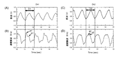
このことは、光電脈波から速度脈波を演算するとより明確になる。図7(A)は、Ch1(チャネル1)から取得された光電脈波であり、図6中のCh1(チャネル1)から取得された光電脈波と同一である。図7(B)は、該光電脈波を速度脈波に演算したものである。このとき、図7(B)では、D1で示す1サイクル内に速度脈波の極大値が2つ以上存在し、そのうち、時間的に最初に到来する極大値a1と時間的にその次に到来する極大値a2との差が大きい。一方で、図7(C)は、Ch2(チャネル2)から取得された光電脈波であり、図6中のCh2(チャネル2)から取得された光電脈波と同一である。図7(D)は、該光電脈波を速度脈波に演算したものである。このとき、図7(D)では、D2で示す1サイクル内に速度脈波の極大値が2つ以上存在するが、そのうち、時間的に最初に到来する極大値a2と時間的にその次に到来する極大値b2の差がほとんどない。
したがって、速度脈波を用いて前記心臓部位の光電脈波を最も反映する部分を抽出する場合、速度脈波の極大値が2つ以上存在し、そのうち、時間的に最初に到来する極大値と時間的にその次に到来する極大値との差が大きいサイクルを抽出することが好ましく、該差は、好ましくは0.5V/s以上であり、より好ましくは1.0V/s以上であり、さらに好ましくは2.1V/s以上である。
したがって、速度脈波を用いて前記心臓部位の光電脈波を最も反映する部分を抽出する場合、速度脈波の極大値が2つ以上存在し、そのうち、時間的に最初に到来する極大値と時間的にその次に到来する極大値との差が大きいサイクルを抽出することが好ましく、該差は、好ましくは0.5V/s以上であり、より好ましくは1.0V/s以上であり、さらに好ましくは2.1V/s以上である。
また、光電脈波から脈波ピーク間隔(本明細書では、「疑似R‐Rインターバル」と定義し、その英訳であるPseudo R-R Intervalを略して「pR‐Rインターバル」と記載することがある。)を演算し、これに基づいて魚類の心臓部位の光電脈波を最も反映する部分を抽出することも好ましい。一般に心電図計測の場合は、R波の間隔としてR‐Rインターバルが用いられ、光電脈波の場合はa‐aインターバルが用いられるが、本発明では、加速度脈波が心臓付近と判断されても波形のピーク高さは不安定であるため、速度脈波に基づいて間隔を演算したpR‐Rインターバルを用いることも好ましい。pR‐Rインターバルを用いる場合には、所定期間におけるpR‐Rインターバルの標準偏差が指標にでき、該標準偏差とは実施例を用いて説明すれば、図8に示すΔdである。心臓付近から取得された場合、通常0.08秒以下、好ましくは0.05秒以下、より好ましくは0.03秒以下であり、下限値は通常0秒より大きい。一方で、心臓から離れた位置から取得された場合は、上記範囲よりも大きい。したがって、pR‐Rインターバルにおいて標準偏差が上記範囲となる期間に相当する光電脈波を、該魚類の心臓部位の光電脈波を最も反映する部分として抽出することができる。
該処理装置は、魚類が遊泳可能な空間に接する壁面に複数の検出器を備え、該複数の検出器を有する測定装置を介して、信号同期の下、魚類の複数部位の光電脈波を所定の検出期間にわたって時系列で取得する取得部、及び該検出期間に取得された複数部位の光電脈波から、該魚類の心臓部位の光電脈波を最も反映する部分を抽出する抽出部を備える態様であってもよい。
該処理装置を前記システムで使用する場合には、該壁面は前記容器の内壁面であってもよい。また、その他の使用態様としては、該壁面を基板等の面とし、例えば、該処理装置を水の入った容器内に静置する態様が挙げられ、好ましくは、水の入った容器の内壁面に接触するように静置する態様等が挙げられる。該基板等は、複数の検出器が備えられ上記取得部及び抽出部がそれらの機能を発揮できるのであれば、その形状や大きさ、素材に特に制限はない。
該処理装置を前記システムで使用する場合には、該壁面は前記容器の内壁面であってもよい。また、その他の使用態様としては、該壁面を基板等の面とし、例えば、該処理装置を水の入った容器内に静置する態様が挙げられ、好ましくは、水の入った容器の内壁面に接触するように静置する態様等が挙げられる。該基板等は、複数の検出器が備えられ上記取得部及び抽出部がそれらの機能を発揮できるのであれば、その形状や大きさ、素材に特に制限はない。
(ストレス状態の解析)
本発明に係るシステムにより、魚類の心臓の状態として該魚類の心臓部位における光電脈波を取得後、例えば非特許文献2で報告されているようにして、魚類のストレス状態を解析してもよい。このとき、該解析のために十分な時間の心臓部位における光電脈波が必要な場合には、本発明に係るシステムにより抽出された光電脈波を時間的に連続した光電脈波に合成してから行ってもよい。そして、該解析により、魚類がストレス状態にあると判別された場合には、該魚類に対してストレス状態を治癒、緩和又は改善等する措置を施すのが好ましい。該措置としては、例えば、水質(例えば、水温、pH、浸透圧、塩濃度、酸素濃度、二酸化炭素濃度、アンモニア濃度、窒素濃度、硬度(カルシウム塩、マグネシウム塩等)等)の最適化、養育(例えば、光量、餌、給餌、魚類の数、魚類の密度、換水頻度等)の最適化、餌に対する嗜好性の検討、殺菌、病魚の検出及び排除等が挙げられる。これらの措置は、いずれも常法に従うことができる。
本発明に係るシステムにより、魚類の心臓の状態として該魚類の心臓部位における光電脈波を取得後、例えば非特許文献2で報告されているようにして、魚類のストレス状態を解析してもよい。このとき、該解析のために十分な時間の心臓部位における光電脈波が必要な場合には、本発明に係るシステムにより抽出された光電脈波を時間的に連続した光電脈波に合成してから行ってもよい。そして、該解析により、魚類がストレス状態にあると判別された場合には、該魚類に対してストレス状態を治癒、緩和又は改善等する措置を施すのが好ましい。該措置としては、例えば、水質(例えば、水温、pH、浸透圧、塩濃度、酸素濃度、二酸化炭素濃度、アンモニア濃度、窒素濃度、硬度(カルシウム塩、マグネシウム塩等)等)の最適化、養育(例えば、光量、餌、給餌、魚類の数、魚類の密度、換水頻度等)の最適化、餌に対する嗜好性の検討、殺菌、病魚の検出及び排除等が挙げられる。これらの措置は、いずれも常法に従うことができる。
(検出開始からストレス状態の判定までのフロー)
本発明では、魚類の複数部位の光電脈波を所定の検出期間にわたって時系列で取得し、該検出期間に取得された複数部位の光電脈波から、該魚類の心臓部位の光電脈波を最も反映する部分を抽出し、好ましくは、該抽出後にストレス状態の解析に適用し、該魚類のストレス状態を判定する。図3は、検出開始S101からストレス状態の判定S106までを示したフローである。検出開始S101からストレス状態の解析S105までは抽出部203が行う。抽出部203としては計算機などが挙げられる。ストレス状態の判定S106は、人が行ってもよいし、抽出部203が行ってもよい。抽出をするのに十分な検出期間が確保され、魚類の複数部位から光電脈波が取得されることが必要であるところ、図3のS102とS103に示す制御によりその実現を図る。
S101では、信号同期の下、魚類の複数部位の光電脈波の検出を開始する。S102では、所定の検出期間が満了したか否かが判定される。所定の検出期間は、上記「取得部」欄に記載した各態様に応じた期間が適用される。S102が否定判定されると、検出を再度行う。一方で、S102が肯定判定されると、次にS103に進み、魚類の複数部位から光電脈波を取得できたか否かが判定される。S103が否定判定されると、検出を再度行う。一方で、S103が肯定判定されると、次にS104に進み、取得された複数部位の光電脈波から、上記「抽出部」欄に記載した各態様に従って、魚類の心臓部位の光電脈波を最も反映する部分を抽出する。S104で抽出が完了すると、S105に進み、例えば非特許文献2で報告されているようにして魚類のストレス状態を解析し、該解析が完了するとS106に進み、該解析結果に基づいて該魚類のストレス状態を判定する。
本発明では、魚類の複数部位の光電脈波を所定の検出期間にわたって時系列で取得し、該検出期間に取得された複数部位の光電脈波から、該魚類の心臓部位の光電脈波を最も反映する部分を抽出し、好ましくは、該抽出後にストレス状態の解析に適用し、該魚類のストレス状態を判定する。図3は、検出開始S101からストレス状態の判定S106までを示したフローである。検出開始S101からストレス状態の解析S105までは抽出部203が行う。抽出部203としては計算機などが挙げられる。ストレス状態の判定S106は、人が行ってもよいし、抽出部203が行ってもよい。抽出をするのに十分な検出期間が確保され、魚類の複数部位から光電脈波が取得されることが必要であるところ、図3のS102とS103に示す制御によりその実現を図る。
S101では、信号同期の下、魚類の複数部位の光電脈波の検出を開始する。S102では、所定の検出期間が満了したか否かが判定される。所定の検出期間は、上記「取得部」欄に記載した各態様に応じた期間が適用される。S102が否定判定されると、検出を再度行う。一方で、S102が肯定判定されると、次にS103に進み、魚類の複数部位から光電脈波を取得できたか否かが判定される。S103が否定判定されると、検出を再度行う。一方で、S103が肯定判定されると、次にS104に進み、取得された複数部位の光電脈波から、上記「抽出部」欄に記載した各態様に従って、魚類の心臓部位の光電脈波を最も反映する部分を抽出する。S104で抽出が完了すると、S105に進み、例えば非特許文献2で報告されているようにして魚類のストレス状態を解析し、該解析が完了するとS106に進み、該解析結果に基づいて該魚類のストレス状態を判定する。
以下に、実施例を用いて本発明をさらに具体的に説明するが、本発明はこれらの実施例に限定されるものではない。
(魚類及びシステム)
本実施例では、容器底面に2つの検出器が配置されたシステムを構築し、魚類としてヒラメを用いた。該ヒラメは高知大学農林海洋科学部から提供を受けたものであり、体長30cm、重さ314g、健康で、水温21℃に温度管理された循環型水槽にて飼育したヒラメである。
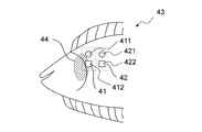
ヒラメと2つの検出器の位置関係は図4に示す通りである。ヒラメ43(ヒラメの心臓44)に対し、チャネル1(図4中の41で示す。その光源は411、検出器は412で示す。)は心臓部位に、チャネル2(図4中の42で示す。その光源は421、検出器は422で示す。)は心臓から離れた場所に配置し、光電脈波を取得している間にヒラメ43が大きく運動したり移動したりすることはなかった。検出器の受光面サイズは1.1mm×1.1mmとし、光源‐検出器の中心間距離は8mmに設定した。図5はチャネル1とチャネル2の寸法等を示したものである。
水温は21℃に管理し、近赤外発光ダイオード(SLR938-CV、中心発光波長λ = 945 nm、 Sanyo)からの光がヒラメに入射され、皮膚反射光および体内からの後方散乱光をPINフォトダイオード(S1336-18BQ, HAMAMATSU)で検出した。DC サーボアンプを介してデータロガー(GL900、GRAPHTEC)にてサンプリング周波数1kHz、ローパスフィルター5Hzを通して6分間、信号を取得した。
本実施例では、容器底面に2つの検出器が配置されたシステムを構築し、魚類としてヒラメを用いた。該ヒラメは高知大学農林海洋科学部から提供を受けたものであり、体長30cm、重さ314g、健康で、水温21℃に温度管理された循環型水槽にて飼育したヒラメである。
ヒラメと2つの検出器の位置関係は図4に示す通りである。ヒラメ43(ヒラメの心臓44)に対し、チャネル1(図4中の41で示す。その光源は411、検出器は412で示す。)は心臓部位に、チャネル2(図4中の42で示す。その光源は421、検出器は422で示す。)は心臓から離れた場所に配置し、光電脈波を取得している間にヒラメ43が大きく運動したり移動したりすることはなかった。検出器の受光面サイズは1.1mm×1.1mmとし、光源‐検出器の中心間距離は8mmに設定した。図5はチャネル1とチャネル2の寸法等を示したものである。
水温は21℃に管理し、近赤外発光ダイオード(SLR938-CV、中心発光波長λ = 945 nm、 Sanyo)からの光がヒラメに入射され、皮膚反射光および体内からの後方散乱光をPINフォトダイオード(S1336-18BQ, HAMAMATSU)で検出した。DC サーボアンプを介してデータロガー(GL900、GRAPHTEC)にてサンプリング周波数1kHz、ローパスフィルター5Hzを通して6分間、信号を取得した。
(実施例1:光電脈波解析)
図6は、チャネル1(Ch1)及びチャネル2(Ch2)から取得された光電脈波データである。チャネル1から取得された光電脈波では、図6中のD1で示す1サイクル内で光電脈波が増加する際に傾きが顕著に小さくなる点aが生じた。図7(A)は、チャネル1から取得された光電脈波であり、図6中のチャネル1の光電脈波と同一である。図7(B)は、該光電脈波を速度脈波に演算したものである。このとき、図7(B)では、D1で示す1サイクル内に速度脈波の極大値が2つ以上存在するのが確認された。このうち、時間的に最初に到来する極大値a1(3.17V/s)と時間的にその次に到来する極大値b1(1.26V/s)との差は、1.91V/sであった。
一方で、チャネル2から取得された光電脈波では、図6中の光電脈波が増加する際に傾きが顕著に変化する点が生じたサイクルは見られなかった。図7(C)は、チャネル2から取得された光電脈波であり、図6中のチャネル2の光電脈波と同一である。図7(D)は、該光電脈波を速度脈波に演算したものである。このとき、図7(D)では、D2で示す1サイクル内に速度脈波の極大値が2つ以上存在するのが確認された。このうち、時間的に最初に到来する極大値a2(2.02V/s)と時間的にその次に到来する極大値b2(2.09V/s)との差は、-0.07V/sであった。
図6は、チャネル1(Ch1)及びチャネル2(Ch2)から取得された光電脈波データである。チャネル1から取得された光電脈波では、図6中のD1で示す1サイクル内で光電脈波が増加する際に傾きが顕著に小さくなる点aが生じた。図7(A)は、チャネル1から取得された光電脈波であり、図6中のチャネル1の光電脈波と同一である。図7(B)は、該光電脈波を速度脈波に演算したものである。このとき、図7(B)では、D1で示す1サイクル内に速度脈波の極大値が2つ以上存在するのが確認された。このうち、時間的に最初に到来する極大値a1(3.17V/s)と時間的にその次に到来する極大値b1(1.26V/s)との差は、1.91V/sであった。
一方で、チャネル2から取得された光電脈波では、図6中の光電脈波が増加する際に傾きが顕著に変化する点が生じたサイクルは見られなかった。図7(C)は、チャネル2から取得された光電脈波であり、図6中のチャネル2の光電脈波と同一である。図7(D)は、該光電脈波を速度脈波に演算したものである。このとき、図7(D)では、D2で示す1サイクル内に速度脈波の極大値が2つ以上存在するのが確認された。このうち、時間的に最初に到来する極大値a2(2.02V/s)と時間的にその次に到来する極大値b2(2.09V/s)との差は、-0.07V/sであった。
(実施例2:pR‐Rインターバル解析)
図8(A)及び(B)は、それぞれ、実施例1のチャネル1(Ch1)及びチャネル2(Ch2)から取得された光電脈波に基づいて、OriginにてAkimaスプラインを用いて0.1秒きざみで0秒から120秒をサンプリングして得たpR‐Rインターバルである。チャネル1(Ch1)から取得された光電脈波に基づくpR‐Rインターバルでは、平均が1.108秒、心拍数に換算すると54.2bpmであり、標準偏差が0.024秒であった。一方で、チャネル2(Ch2)から取得された光電脈波に基づくpR‐Rインターバルでは、平均が1.111秒、心拍数に換算すると54.0bpmであり、標準偏差が0.096秒であった。
図8(A)及び(B)は、それぞれ、実施例1のチャネル1(Ch1)及びチャネル2(Ch2)から取得された光電脈波に基づいて、OriginにてAkimaスプラインを用いて0.1秒きざみで0秒から120秒をサンプリングして得たpR‐Rインターバルである。チャネル1(Ch1)から取得された光電脈波に基づくpR‐Rインターバルでは、平均が1.108秒、心拍数に換算すると54.2bpmであり、標準偏差が0.024秒であった。一方で、チャネル2(Ch2)から取得された光電脈波に基づくpR‐Rインターバルでは、平均が1.111秒、心拍数に換算すると54.0bpmであり、標準偏差が0.096秒であった。
11、43 ヒラメ
12、44 ヒラメの心臓
13、15、412、422 検出器
14、411、421 光源
200 システム
201 容器
202 取得部
203 抽出部(演算部を含む。)
204 検出器
205 光源
206 検出器選択信号生成部
207 信号処理回路
208 検出器選択回路
209 増幅回路
210 駆動回路
211 同期回路
212 魚類(対象とする魚)
41 チャネル1
42 チャネル2
12、44 ヒラメの心臓
13、15、412、422 検出器
14、411、421 光源
200 システム
201 容器
202 取得部
203 抽出部(演算部を含む。)
204 検出器
205 光源
206 検出器選択信号生成部
207 信号処理回路
208 検出器選択回路
209 増幅回路
210 駆動回路
211 同期回路
212 魚類(対象とする魚)
41 チャネル1
42 チャネル2
Claims (8)
- 容器と処理装置とを含み、
該容器は、該容器の内壁面に複数の検出器が備えられ、該容器内の魚類からみて該検出器側と逆側に該魚類が遊泳可能な空間を含み、
該処理装置は、
該複数の検出器を有する測定装置を介して、信号同期の下、魚類の複数部位の光電脈波を所定の検出期間にわたって時系列で取得する取得部、及び
該検出期間に取得された複数部位の光電脈波から、該魚類の心臓部位の光電脈波を最も反映する部分を抽出する抽出部を備える、
魚類の心臓の状態をモニタリングするシステム。 - 取得された複数部位の光電脈波から速度脈波を演算し、
前記心臓部位の光電脈波を最も反映する部分を抽出することが、取得された複数部位の光電脈波において、ある極小値と時間的に次に到来する次の極小値との間を1サイクルとした場合に、該1サイクルに相当する期間内の速度脈波に極大値が2つ以上存在し、そのうち、時間的に最初に到来する極大値と時間的にその次に到来する極大値との差が0.5V/s以上であるサイクルを抽出することである、請求項1に記載のシステム。 - 該検出期間に取得された複数部位の光電脈波から疑似R‐Rインターバルを演算し、
前記心臓部位の光電脈波を最も反映する部分を抽出することが、該疑似R‐Rインターバルの標準偏差が0.08以下となる期間に対応する光電脈波を抽出することである、請求項1に記載のシステム。 - 前記複数の検出器が等間隔で存在する、請求項1~3のいずれか1項に記載のシステム。
- 前記魚類がヒラメ又はカレイである、請求項1~4のいずれか1項に記載のシステム。
- 前記検出器が光を検出する素子で構成されている、請求項1~5のいずれか1項に記載のシステム。
- 複数の検出器で、信号同期の下、魚類の複数部位の光電脈波を所定の検出期間にわたって時系列で取得する工程、及び
該検出期間に取得された複数部位の光電脈波から、該魚類の心臓部位の光電脈波を最も反映する部分を抽出する工程
を含む、魚類の心臓の状態をモニタリングする方法。 - 魚類が遊泳可能な空間に接する壁面に複数の検出器を備え、
該複数の検出器を有する測定装置を介して、信号同期の下、魚類の複数部位の光電脈波を所定の検出期間にわたって時系列で取得する取得部、及び
該検出期間に取得された複数部位の光電脈波から、該魚類の心臓部位の光電脈波を最も反映する部分を抽出する抽出部を備える、処理装置。
Priority Applications (2)
| Application Number | Priority Date | Filing Date | Title |
|---|---|---|---|
| CA3074967A CA3074967C (en) | 2017-09-06 | 2018-08-01 | System for monitoring heart condition of fish |
| NO20200403A NO348542B1 (en) | 2017-09-06 | 2020-04-02 | System for monitoring heart condition of fish |
Applications Claiming Priority (2)
| Application Number | Priority Date | Filing Date | Title |
|---|---|---|---|
| JP2017171608A JP6956941B2 (ja) | 2017-09-06 | 2017-09-06 | 魚類の心臓の状態をモニタリングするシステム |
| JP2017-171608 | 2017-09-06 |
Publications (1)
| Publication Number | Publication Date |
|---|---|
| WO2019049564A1 true WO2019049564A1 (ja) | 2019-03-14 |
Family
ID=65633845
Family Applications (1)
| Application Number | Title | Priority Date | Filing Date |
|---|---|---|---|
| PCT/JP2018/028869 Ceased WO2019049564A1 (ja) | 2017-09-06 | 2018-08-01 | 魚類の心臓の状態をモニタリングするシステム |
Country Status (4)
| Country | Link |
|---|---|
| JP (1) | JP6956941B2 (ja) |
| CA (1) | CA3074967C (ja) |
| NO (1) | NO348542B1 (ja) |
| WO (1) | WO2019049564A1 (ja) |
Cited By (2)
| Publication number | Priority date | Publication date | Assignee | Title |
|---|---|---|---|---|
| CN110988292A (zh) * | 2019-12-24 | 2020-04-10 | 山东师范大学 | 基于鱼类心电特征的水体小分子污染物检测方法及系统 |
| CN115176746A (zh) * | 2022-08-16 | 2022-10-14 | 厦门大学 | 一种可控温的鱼类麻醉状态保持装置 |
Families Citing this family (1)
| Publication number | Priority date | Publication date | Assignee | Title |
|---|---|---|---|---|
| KR102741061B1 (ko) * | 2024-06-05 | 2024-12-10 | 제주대학교 산학협력단 | 넙치 암수 판별 장치 |
Citations (3)
| Publication number | Priority date | Publication date | Assignee | Title |
|---|---|---|---|---|
| JP2009195376A (ja) * | 2008-02-20 | 2009-09-03 | Hiroshima Univ | 魚類の心拍動計測方法及び計測装置 |
| JP2013116092A (ja) * | 2011-12-05 | 2013-06-13 | Japan Aerospace Exploration Agency | 魚類観測装置および方法 |
| US20140221780A1 (en) * | 2011-07-22 | 2014-08-07 | President And Fellows Of Harvard College | Complexity based methods and systems for detecting depression |
Family Cites Families (1)
| Publication number | Priority date | Publication date | Assignee | Title |
|---|---|---|---|---|
| CN106645673B (zh) * | 2017-02-28 | 2018-05-18 | 山东省科学院生物研究所 | 一种利用斑马鱼评价化合物急性毒性的装置及其工作方法 |
-
2017
- 2017-09-06 JP JP2017171608A patent/JP6956941B2/ja active Active
-
2018
- 2018-08-01 WO PCT/JP2018/028869 patent/WO2019049564A1/ja not_active Ceased
- 2018-08-01 CA CA3074967A patent/CA3074967C/en active Active
-
2020
- 2020-04-02 NO NO20200403A patent/NO348542B1/en unknown
Patent Citations (3)
| Publication number | Priority date | Publication date | Assignee | Title |
|---|---|---|---|---|
| JP2009195376A (ja) * | 2008-02-20 | 2009-09-03 | Hiroshima Univ | 魚類の心拍動計測方法及び計測装置 |
| US20140221780A1 (en) * | 2011-07-22 | 2014-08-07 | President And Fellows Of Harvard College | Complexity based methods and systems for detecting depression |
| JP2013116092A (ja) * | 2011-12-05 | 2013-06-13 | Japan Aerospace Exploration Agency | 魚類観測装置および方法 |
Cited By (3)
| Publication number | Priority date | Publication date | Assignee | Title |
|---|---|---|---|---|
| CN110988292A (zh) * | 2019-12-24 | 2020-04-10 | 山东师范大学 | 基于鱼类心电特征的水体小分子污染物检测方法及系统 |
| CN110988292B (zh) * | 2019-12-24 | 2022-10-04 | 山东师范大学 | 基于鱼类心电特征的水体小分子污染物检测方法及系统 |
| CN115176746A (zh) * | 2022-08-16 | 2022-10-14 | 厦门大学 | 一种可控温的鱼类麻醉状态保持装置 |
Also Published As
| Publication number | Publication date |
|---|---|
| JP2019041734A (ja) | 2019-03-22 |
| CA3074967C (en) | 2022-06-28 |
| NO20200403A1 (en) | 2020-04-02 |
| NO348542B1 (en) | 2025-03-03 |
| CA3074967A1 (en) | 2019-03-14 |
| JP6956941B2 (ja) | 2021-11-02 |
Similar Documents
| Publication | Publication Date | Title |
|---|---|---|
| US11330985B2 (en) | Near-infrared optical imaging system for hemodynamic imaging, pulse monitoring, and mapping spatio-temporal features | |
| Zheng et al. | Feasibility of imaging photoplethysmography | |
| US7470235B2 (en) | Pulse wave detecting device and method therefor | |
| Kuklina et al. | Real-time monitoring of water quality using fish and crayfish as bio-indicators: a review | |
| WO2019049564A1 (ja) | 魚類の心臓の状態をモニタリングするシステム | |
| WO2014016963A1 (ja) | 光生体計測装置及びそれを用いた解析方法 | |
| CN107320112B (zh) | 微循环的多参数成像检测方法及装置 | |
| Duarte et al. | Measurement of sole activity by digital image analysis | |
| WO2020186008A1 (en) | Non-contact multispectral imaging for blood oxygenation level and perfusion measurement | |
| US20150272489A1 (en) | Device, system and method for tumor detection and/or monitoring | |
| US20190076005A1 (en) | Fluorescent imaging device for plaque monitoring and multi-imaging system using same | |
| Zheng et al. | The preliminary investigation of imaging photoplethysmographic system | |
| Lychagov et al. | Noninvasive hemoglobin measurements with photoplethysmography in wrist | |
| Fedotov et al. | Study of contractile activity of the crayfish heart with the aid of a new non-invasive technique | |
| EP3339856B1 (en) | Method for ethological monitoring of crayfish and system for this method | |
| Kozák et al. | Crayfish as tools of water quality monitoring | |
| Andersen et al. | Temperate Drosophila preserve cardiac function at low temperature | |
| Piza et al. | The hippocampus of the common marmoset is a GPS, but G is for gaze | |
| CN118697278A (zh) | 一种基于多模态脑机接口的脑卒中监护方法、装置和系统 | |
| WO2017014167A1 (en) | Object information acquiring apparatus and object information acquiring method | |
| CN206261606U (zh) | 一种体外鼻咽腔体静脉血氧饱和度成像装置 | |
| Bautista López et al. | Branchial motion assessment in abalone using photoplethysmography | |
| JP6501432B2 (ja) | 血流動態画像化診断装置及び診断方法 | |
| US10617319B2 (en) | Photoacoustic apparatus | |
| Hamed et al. | Sympatho-vagal balance and intrinsic sinoatrial node activity in larval zebrafish quantified by heart rate variability |
Legal Events
| Date | Code | Title | Description |
|---|---|---|---|
| 121 | Ep: the epo has been informed by wipo that ep was designated in this application |
Ref document number: 18853264 Country of ref document: EP Kind code of ref document: A1 |
|
| ENP | Entry into the national phase |
Ref document number: 3074967 Country of ref document: CA |
|
| NENP | Non-entry into the national phase |
Ref country code: DE |
|
| 122 | Ep: pct application non-entry in european phase |
Ref document number: 18853264 Country of ref document: EP Kind code of ref document: A1 |