WO2019043802A1 - Échangeur de chaleur - Google Patents
Échangeur de chaleur Download PDFInfo
- Publication number
- WO2019043802A1 WO2019043802A1 PCT/JP2017/031030 JP2017031030W WO2019043802A1 WO 2019043802 A1 WO2019043802 A1 WO 2019043802A1 JP 2017031030 W JP2017031030 W JP 2017031030W WO 2019043802 A1 WO2019043802 A1 WO 2019043802A1
- Authority
- WO
- WIPO (PCT)
- Prior art keywords
- flow
- heat exchanger
- refrigerant
- flow path
- plate
- Prior art date
Links
Images


Classifications
-
- F—MECHANICAL ENGINEERING; LIGHTING; HEATING; WEAPONS; BLASTING
- F28—HEAT EXCHANGE IN GENERAL
- F28D—HEAT-EXCHANGE APPARATUS, NOT PROVIDED FOR IN ANOTHER SUBCLASS, IN WHICH THE HEAT-EXCHANGE MEDIA DO NOT COME INTO DIRECT CONTACT
- F28D9/00—Heat-exchange apparatus having stationary plate-like or laminated conduit assemblies for both heat-exchange media, the media being in contact with different sides of a conduit wall
- F28D9/0031—Heat-exchange apparatus having stationary plate-like or laminated conduit assemblies for both heat-exchange media, the media being in contact with different sides of a conduit wall the conduits for one heat-exchange medium being formed by paired plates touching each other
- F28D9/0043—Heat-exchange apparatus having stationary plate-like or laminated conduit assemblies for both heat-exchange media, the media being in contact with different sides of a conduit wall the conduits for one heat-exchange medium being formed by paired plates touching each other the plates having openings therein for circulation of at least one heat-exchange medium from one conduit to another
- F28D9/005—Heat-exchange apparatus having stationary plate-like or laminated conduit assemblies for both heat-exchange media, the media being in contact with different sides of a conduit wall the conduits for one heat-exchange medium being formed by paired plates touching each other the plates having openings therein for circulation of at least one heat-exchange medium from one conduit to another the plates having openings therein for both heat-exchange media
-
- F—MECHANICAL ENGINEERING; LIGHTING; HEATING; WEAPONS; BLASTING
- F28—HEAT EXCHANGE IN GENERAL
- F28D—HEAT-EXCHANGE APPARATUS, NOT PROVIDED FOR IN ANOTHER SUBCLASS, IN WHICH THE HEAT-EXCHANGE MEDIA DO NOT COME INTO DIRECT CONTACT
- F28D9/00—Heat-exchange apparatus having stationary plate-like or laminated conduit assemblies for both heat-exchange media, the media being in contact with different sides of a conduit wall
- F28D9/0031—Heat-exchange apparatus having stationary plate-like or laminated conduit assemblies for both heat-exchange media, the media being in contact with different sides of a conduit wall the conduits for one heat-exchange medium being formed by paired plates touching each other
- F28D9/0043—Heat-exchange apparatus having stationary plate-like or laminated conduit assemblies for both heat-exchange media, the media being in contact with different sides of a conduit wall the conduits for one heat-exchange medium being formed by paired plates touching each other the plates having openings therein for circulation of at least one heat-exchange medium from one conduit to another
- F28D9/0056—Heat-exchange apparatus having stationary plate-like or laminated conduit assemblies for both heat-exchange media, the media being in contact with different sides of a conduit wall the conduits for one heat-exchange medium being formed by paired plates touching each other the plates having openings therein for circulation of at least one heat-exchange medium from one conduit to another with U-flow or serpentine-flow inside conduits; with centrally arranged openings on the plates
-
- F—MECHANICAL ENGINEERING; LIGHTING; HEATING; WEAPONS; BLASTING
- F28—HEAT EXCHANGE IN GENERAL
- F28F—DETAILS OF HEAT-EXCHANGE AND HEAT-TRANSFER APPARATUS, OF GENERAL APPLICATION
- F28F13/00—Arrangements for modifying heat-transfer, e.g. increasing, decreasing
- F28F13/06—Arrangements for modifying heat-transfer, e.g. increasing, decreasing by affecting the pattern of flow of the heat-exchange media
- F28F13/12—Arrangements for modifying heat-transfer, e.g. increasing, decreasing by affecting the pattern of flow of the heat-exchange media by creating turbulence, e.g. by stirring, by increasing the force of circulation
-
- F—MECHANICAL ENGINEERING; LIGHTING; HEATING; WEAPONS; BLASTING
- F28—HEAT EXCHANGE IN GENERAL
- F28F—DETAILS OF HEAT-EXCHANGE AND HEAT-TRANSFER APPARATUS, OF GENERAL APPLICATION
- F28F3/00—Plate-like or laminated elements; Assemblies of plate-like or laminated elements
-
- F—MECHANICAL ENGINEERING; LIGHTING; HEATING; WEAPONS; BLASTING
- F28—HEAT EXCHANGE IN GENERAL
- F28F—DETAILS OF HEAT-EXCHANGE AND HEAT-TRANSFER APPARATUS, OF GENERAL APPLICATION
- F28F3/00—Plate-like or laminated elements; Assemblies of plate-like or laminated elements
- F28F3/08—Elements constructed for building-up into stacks, e.g. capable of being taken apart for cleaning
-
- F—MECHANICAL ENGINEERING; LIGHTING; HEATING; WEAPONS; BLASTING
- F28—HEAT EXCHANGE IN GENERAL
- F28F—DETAILS OF HEAT-EXCHANGE AND HEAT-TRANSFER APPARATUS, OF GENERAL APPLICATION
- F28F2210/00—Heat exchange conduits
- F28F2210/02—Heat exchange conduits with particular branching, e.g. fractal conduit arrangements
Definitions
- the present invention relates to a heat exchanger that exchanges heat between fluids flowing in a plurality of flow paths.
- a high pressure resistant heat exchanger is provided in the middle of a pipeline for supplying hydrogen from the hydrogen source of the hydrogen supply station to the fuel cell vehicle to cool the hydrogen (for example, see Patent Document 1).
- the hydrogen supply station by passing hydrogen to a plurality of compressors in order, multistage compression may be performed in which the hydrogen once compressed by the compressor is further compressed by the compressor of the next stage. In this case, it is convenient to cool the hydrogen at each pressure step with one multi-tube heat exchanger (see, for example, Patent Document 2).
- the present invention has been made in view of the above problems, and an object of the present invention is to provide a compact and inexpensive heat exchanger which is higher in efficiency and higher in pressure resistance.
- the heat exchanger according to the present invention is a heat exchanger that performs heat exchange between fluids flowing in a plurality of flow paths, and the flow paths are the first It has a first flow path through which the fluid flows, and a second flow path through which the second fluid having a different temperature from the first fluid flows, and the first flow path and the second flow path are orthogonal to the flow path direction Between a plurality of upstream portions and a plurality of downstream portions parallel to the flow passage direction and the direction orthogonal to the stacking direction, and between the upstream portion and the downstream portion. And a plurality of flow paths immediately before are branched into two flow paths, and the adjacent flow paths merge to form the next plurality of flow paths, A plurality of stages are provided between the upstream portion and the downstream portion.
- the fluid flowing in one of the first flow path and the second flow path flows near the flow path wall and receives a heat from the flow path wall, thereby causing a large temperature rise. It is repeated that the part is transferred to the central part, and the part flowing in the central part is transferred to the channel wall side because the heat flowing through the central part is small and the heat received from the channel wall is small.
- the fluid flowing in the other flow channel flows near the flow channel wall and dissipates heat to the flow channel wall, so that the portion where the temperature drop is large is transferred to the central portion, and flows in the central portion conversely It is repeated that the portion with a small temperature drop is transferred to the flow path wall side because the heat dissipation to the flow path wall is small.
- the temperature difference between the fluid and the flow path wall can be increased, and the efficiency of heat dissipation and heat reception can be enhanced.
- the N flow paths immediately before are branched into two branch flow paths, and the adjacent flow branch paths join except for the two outer flow paths to join the next N + 1 flow paths.
- the first bifurcated portion to be formed and N-1 except for the outer two out of the immediately preceding N + 1 flow paths are branched into two branch paths and adjacent to each other including the outer two.
- the first and second branch junctions are divided into a second branch junction where the branch channels join together to form the next N channels, and the first branch junction and the second branch junction include the upstream portion and the downstream portion.
- a plurality of stages may be provided alternately.
- the flow channels which were initially N in number, are repeatedly increased and decreased in number by N + 1 and N, and the flow channel area is appropriately suppressed without excessively increasing or decreasing the number of flow channels.
- the two branch channels branched or merged at the branch junction are symmetrical with respect to the flow channel direction, and when the angle at the top of the branch is 180 ° or less, it is easy to branch while maintaining the laminar flow state.
- a first plate and a second plate are stacked, and the first flow path is formed as a groove between the surface of the first plate and the back surface of the second plate;
- the two flow paths may be formed as a groove between the surface of the second plate and the back surface of the first plate, and the first plate and the second plate may be diffusion bonded.
- the first flow path and the second flow path can be configured as a so-called microchannel in a large number of small diameter paths, and the flow path wall area can be increased, and the first flow path and the second flow path can be closely arranged. Heat exchange efficiency can be improved.
- high withstand voltage can be realized by high strength bonding of diffusion bonding.
- the second fluid is a refrigerant having a temperature lower than that of the first fluid
- the first fluid is a hydrogen gas having a temperature higher than that of the second fluid, which is suitable for use at a hydrogen supply station or the like.
- the second fluid is a refrigerant having a temperature lower than that of the first fluid
- the first fluid is a fluid having a temperature higher than that of the second fluid
- the branch channel in the one channel is the channel branch in the second channel. It is preferable from the viewpoint of the heat exchange performance and the pressure resistance performance that it is formed narrower than the passage.
- the flow path includes three or more flow paths including the first flow path and the second flow path, and the respective flow paths are provided in the form of a stack in the stacking direction, and the upstream portion, the The downstream portion may have the branching / joining portion.
- the fluid flowing in one of the first flow passage and the second flow passage flows near the flow passage wall and receives heat from the flow passage wall by providing the branching / joining portion.
- the part where the temperature rise is large is transferred to the central part, and conversely, the small part of the temperature rise is transferred to the channel wall side because it is flowing in the central part and the heat reception from the channel wall is small. Repeated.
- the fluid flowing in the other flow channel flows near the flow channel wall and dissipates heat to the flow channel wall, so that the portion where the temperature drop is large is transferred to the central portion, and flows in the central portion conversely It is repeated that the portion with a small temperature drop is transferred to the flow path wall side because the heat dissipation to the flow path wall is small.
- the temperature difference between the fluid and the flow path wall can be increased, and the efficiency of heat dissipation and heat reception can be enhanced.
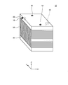
- FIG. 1 is a perspective view of a heat exchanger according to a first embodiment.
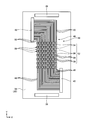
- FIG. 2 is an exploded perspective view of the heat exchanger according to the first embodiment.
- FIG. 3 is a top view of the upper end plate.
- FIG. 4 is a bottom view of the lower end plate.
- FIG. 5 is a top view of the first plate and the lower end plate.
- FIG. 6 is a partially enlarged view of the refrigerant narrow groove group.
- FIG. 7 is a bottom view of the second plate and the upper end plate.
- FIG. 8 is a partially enlarged cross-sectional side view of the plate stack portion.
- FIG. 9 is a bottom view of the first plate.
- FIG. 10-1 is an enlarged view of a first branch joining portion on the refrigerant flow path on the upper surface of the first plate.
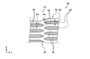
- FIG. 10-2 is an enlarged view of a first branch junction on the hydrogen flow channel on the lower surface of the first plate.
- FIG. 11 is a top view of the second plate.
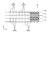
- FIG. 12 is a schematic view for explaining the operation of the honeycomb portion.
- FIG. 13 is a perspective view of a heat exchanger according to a second embodiment.
- FIG. 14 is an exploded perspective view of the heat exchanger according to the second embodiment.
- FIG. 15 is a top view of the upper end plate in the second embodiment.
- FIG. 16 is a top view of the first plate in the second embodiment.
- FIG. 17 is a top view of the second plate in the second embodiment.
- FIG. 18 is a top view of the third plate in the second embodiment.
- the heat exchanger 10 As shown in FIG. 1, the heat exchanger 10 according to the first embodiment is box-shaped, and has a hydrogen inlet 12, a hydrogen outlet 14, a refrigerant inlet 16, and a refrigerant outlet 18. .
- a refrigerant channel (second channel) is formed between the refrigerant inlet 16 and the refrigerant outlet 18, and a hydrogen channel (first channel) is formed between the hydrogen inlet 12 and the hydrogen outlet 14 Then, heat exchange is performed between the refrigerant (second fluid) and hydrogen (first fluid) flowing in these flow paths.
- the heat exchanger 10 is provided, for example, in a gas supply line between the hydrogen storage tank and the vehicle-side fuel tank when hydrogen is filled from the hydrogen storage tank to the fuel tank of the fuel cell vehicle at the hydrogen supply station.
- 100 MPa hydrogen can be cooled to about -40.degree.
- the refrigerant for example, FP-40 of brine is used.
- FP-40 has good thermal performance, high heat transfer coefficient, low viscosity, and is suitable from the viewpoints of cost and hygiene.
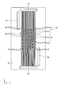
- the heat exchanger 10 has an upper header 20, a lower header 22, and a plate laminate portion 24 provided therebetween.
- a hydrogen inlet 12 is provided on the rear side in the Y direction on the upper surface of the upper header 20, a hydrogen outlet 14 is provided on the near side in the Y direction, and a refrigerant inlet 16 is provided on the right side on the near side in the Y direction.
- the refrigerant outlet port 18 is provided on the left side surface on the back side in the Y direction, and each joint can be connected.
- the hydrogen inlet 12 and the hydrogen outlet 14 penetrate in the Z direction.
- the refrigerant inlet 16 and the refrigerant outlet 18 are slightly bent in the X direction in the upper header 20 and then bent downward. It has been confirmed by the inventor that the heat exchanger 10 can be configured to be small in size, and for example, mounting on a dispenser of a hydrogen supply station (corresponding to a weighing machine of a gas station) is also feasible.
- the plate laminated portion 24 is a portion where heat exchange is performed between hydrogen and the refrigerant, the depth direction (Y direction) in this portion is the flow path direction, hydrogen flows from the back to the front, and the refrigerant is the front. Flow from the back.
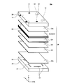
- the plate lamination portion 24 is configured by laminating four types of plates in the Z direction (stacking direction) which is the height direction. That is, an upper end plate 28 disposed immediately below the upper header 20, a lower end plate 30 disposed immediately above the lower header 22, and a first plate 32 in which a plurality of plates are alternately disposed therebetween And the second plate 34. For example, 92 sheets of the first plate 32 and the second plate 34 are stacked, respectively.
- the upper header 20, the lower header 22, the upper end plate 28, the lower end plate 30, the first plate 32, and the second plate 34 are stainless steel, for example, SUS316L, and are joined by diffusion bonding.
- the flow path wall and the entire structure become high strength, and the heat conductivity and corrosion resistance are excellent, and there is no corrosion even to the brine of the refrigerant.
- a copper material, steel material, aluminum material or the like having a high heat transfer coefficient can be used besides stainless steel, and materials different depending on the part may be used. Further, according to the diffusion bonding, the plates are firmly bonded to each other, and a high withstand voltage specification is obtained.
- the upper end plate 28, the lower end plate 30, the first plate 32, and the second plate 34 have a thickness of, for example, 1.2 mm, and identification notches not shown are provided at different positions on the side surfaces.
- the 1st plate 32 and the 2nd plate 34 are shown few for the relationship of illustration representation.
- the 1st plate 32 and the 2nd plate 34 are shown further smaller, and one part is overlap
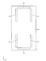
- the upper end plate 28 has a hydrogen supply hole 36 extending in the X direction near the upper side of the paper in a top view, a hydrogen discharge hole 38 extending in the X direction near the lower side of the paper, A refrigerant supply hole 40 extending in the Y direction in the vicinity of the lower right side and a refrigerant discharge hole 42 extending in the Y direction in the vicinity of the left side in the upper side of the drawing are provided.
- the hydrogen supply holes 36, the hydrogen discharge holes 38, the refrigerant supply holes 40, and the refrigerant discharge holes 42 are long rectangles, and provided in the upper end plate 28, the first plate 32, the second plate 34 and the lower end plate 30, respectively.
- a through hole is formed in the portion 24, and a groove 35 is provided on the upper surface of the lower header 22 (see FIG. 2) at a position corresponding thereto.
- the hydrogen supply hole 36 is in communication with the lower opening of the hydrogen inlet 12 (see FIG. 2), and the hydrogen discharge hole 38 is in communication with the lower opening of the hydrogen outlet 14.
- the refrigerant supply hole 40 communicates with the lower opening of the refrigerant inlet 16, and the refrigerant discharge hole 42 communicates with the lower opening of the refrigerant outlet 42.
- the hydrogen supply holes 36 and the hydrogen discharge holes 38 are disposed symmetrically in the vertical and horizontal directions.
- the refrigerant supply holes 40 and the refrigerant discharge holes 42 are arranged point-symmetrically with respect to the center point of the first plate 32.
- the lower surface (rear surface) of the upper end plate 28 has the same shape as the lower surface (see FIG. 7) of the second plate 34 described later.
- the lower surface of the lower end plate 30 is mirror-symmetrical to the upper surface of the upper end plate 28 shown in FIG. Therefore, the hydrogen supply holes 36, the hydrogen discharge holes 38, the refrigerant supply holes 40, and the refrigerant discharge holes 42 (hereinafter collectively referred to as "penetrating elements") overlap without deviation in the transmissive view from the top in the product state after assembly. become. As will be described later, these penetrating elements also overlap in the first plate 32 and the second plate 34.
- the upper surface of the lower end plate 30 has the same shape as the upper surface (see FIG. 5) of the first plate 32 shown below.
- the top surface of the first plate 32 is arranged in the same manner as the top surface of the upper end plate 28 (see FIG. 3).
- the upper surface of the first plate 32 further has a refrigerant narrow groove group 46 communicating the refrigerant supply holes 40 with the refrigerant discharge holes 42.
- the refrigerant fine groove group 46 includes 70 (N) refrigerant upstream narrow passages (upstream portion) 48 communicating with the refrigerant supply holes 40 and 70 refrigerant downstream narrow passages (downstream portion) communicating with the refrigerant discharge holes 42. And a honeycomb portion 52 repeating branching and merging between the refrigerant upstream narrow passage 48 and the refrigerant downstream narrow passage 50 to form a multistage flat hexagonal shape.
- the 70 refrigerant upstream narrow passages 48 and the refrigerant downstream narrow passages 50 are orthogonal to the flow direction (Y direction) and the stacking direction (Z direction), except for the bent portion closest to the refrigerant supply holes 40 and the refrigerant discharge holes 42. There is a portion parallel to the X direction which is the depth direction, and the honeycomb portion 52 is provided therebetween.
- the refrigerant upstream narrow passages 48 respectively advance leftward from the refrigerant supply holes 40, are bent upward by 90 °, and are connected to the honeycomb portion 52.
- the refrigerant downstream narrow passage 50 proceeds from the refrigerant discharge hole 42 to the right, is bent downward by 90 °, and reaches the refrigerant discharge hole 42.
- the honeycomb portion 52 extends in the Y direction at a portion between the hydrogen supply hole 36 and the hydrogen discharge hole 38.
- the refrigerant narrow passage group 46 a portion on the right side in FIG. 5 is long in the refrigerant downstream passage 50 communicating with the refrigerant discharge hole 42, and short in the refrigerant upstream passage 48 communicating with the refrigerant supply hole 40.
- the refrigerant downstream narrow passage 50 communicating with the refrigerant discharge hole 42 is short, and the refrigerant upstream narrow passage 48 communicating with the refrigerant supply hole 40 is long. Therefore, in the refrigerant narrow passage group 46, the distance between the refrigerant supply hole 40 and the refrigerant discharge hole 42 is almost equal on either side.
- the refrigerant narrow groove group 46 is also provided on the lower surface of the second plate 34 (see FIG. 7) or the lower surface of the upper end plate 28 so as to be mirror image symmetrical with FIG. Form a flow path.
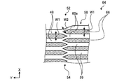
- the honeycomb part 52 is a straight line formed between the first branch and junction part 54, the second branch and junction part 56, and the first branch and junction part 54 and the second branch junction part 56. It has the flow-path part 58, and each provided in multiple steps.
- the straight flow path portion 58 is formed with 71 parallel, equally spaced intermediate straight narrow paths (straight flow paths) 59 downstream of the first branch junction 54, and 70 downstream of the second branch junction 56.
- Parallel, equally spaced, intermediate linear channels 59 of the book are formed.
- the intermediate linear channel 59 is formed to be appropriately long, and the growth portion of the flow is activated to easily obtain a laminar flow and reduce the pressure loss.
- the immediately preceding 70 (N) refrigerant upstream narrow passages 48 or the intermediate straight narrow passages 59 are branched into two branch passages 60, 60 and adjacent except for the outer two.
- the branch channels 60, 60 are joined together to form the next 71 (N + 1) middle straight narrow paths 59.
- 69 (N-1) out of the 71 previous flow paths except for the outer 2 sides are respectively branched into 2 branch flow paths 62 and 62 and the outer 2 side
- Adjacent branch channels 62 and 62 join together to form the next 70 intermediate straight narrow passages 59 or refrigerant downstream narrow passages 50.
- the first branch / join portion 54 and the second branch / join portion 56 are provided alternately seven times at equal intervals between the refrigerant upstream narrow passage 48 and the refrigerant downstream narrow passage 50 (see FIG. 5). Therefore, there are 71 flow paths and seven slightly wide portions, and 70 flow paths are formed between them to form six slightly narrow portions.
- an intermediate linear narrow passage 59 parallel to the flow direction is formed between the first branch junction 54 and the second branch junction 56 adjacent in the flow direction.
- the two branch channels 60, 60 or 62, 62 branched by the first branch junction 54 and the second branch junction 56 are symmetrical with respect to the flow direction, and the top of the branch or junction has an acute angle (for example, 45 °).
- the top angle may be 180 degrees or less.
- the top may be rounded.
- the branching unit and the joining unit are close to each other, and the branching and the joining are performed almost simultaneously.
- honeycomb part 52 a large number of flat hexagonal middle ridge parts 66 are formed in the upper, lower, left, and right multi-stage layers by the first branch and junction part 54, the second branch and junction part 56, and the straight channel part 58, It has a kind of honeycomb shape.
- each passage is 0.5 mm
- the depth is 0.25 mm in a semicircular cross section
- the Y-direction pitches are each 1.0 mm.
- the lower surface of the second plate 34 is mirror-symmetrical to the upper surface of the first plate 32 shown in FIG. Therefore, as shown in FIG. 8, the upper surface wall and the lower surface wall are formed when the upper surface of the first plate 32 and the lower surface of the second plate 34 abut each other as shown in FIG.
- the dimensions are 0.5 mm (0.25 mm ⁇ 2).
- the flow channel formed by each groove has a circular cross-sectional shape with a diameter of 0.5 mm, and the flow tends to be stable.
- the first flow path which is a hydrogen flow path
- the second flow path which is a refrigerant flow path
- the flow of heat from the high temperature side hydrogen flow channel to the low temperature side refrigerant flow channel is schematically indicated by arrows in order to facilitate understanding.
- heat exchange that is, heat radiation and heat reception
- Z direction the thickness direction of the thin plate
- X direction the left and right wall directions
- the penetrating elements are naturally mirror-symmetrical to the upper surface (see FIG. 5), and the lower surface of the lower end plate 30 (see FIG. 4) and the second plate It is arranged in the same manner as the lower surface 34 (see FIG. 7).
- a hydrogen fine groove group 64 is provided which linearly communicates the upper hydrogen supply hole 36 and the lower hydrogen discharge hole 38.
- the hydrogen fine groove groups 64 are vertically and horizontally symmetrical.
- the hydrogen fine groove group 64 is similarly provided on the upper surface (see FIG. 11) of the second plate 34, and is overlapped vertically to constitute a microchannel having a small diameter, thereby forming a hydrogen flow path.
- the hydrogen flow channel is formed as a groove between the upper surface of the first plate 32 and the lower surface of the second plate 34
- the refrigerant flow channel is a groove between the upper surface of the second plate 34 and the lower surface of the first plate 32
- the hydrogen fine groove group 64 has a honeycomb portion 52.
- the honeycomb portion 52 basically has the same shape as that of the refrigerant fine groove group 46 (see FIG. 5), and includes 10 hydrogen upstream narrow passages (upstream portion) 68 communicating with the hydrogen supply holes 36, and hydrogen discharge Branching and merging are repeated between 10 hydrogen downstream channels (downstream portion) 70 communicating with the holes 38, the hydrogen upstream channel 68 and the hydrogen downstream channel 70 to form multistage flat hexagons. .
- Each of the 70 hydrogen upstream narrow passages 68 and the hydrogen downstream narrow passages 70 have the same shape and arrangement as the X-direction straight portions of the refrigerant downstream narrow passages 50 (see FIG. 5) and the refrigerant upstream narrow passages 48 on the upper surface side. Overlap in top view.
- the honeycomb portion 52 basically has the same shape and the same arrangement as those provided on the refrigerant flow path on the upper surface side, and overlaps in the upper surface transparent view.
- the honeycomb portion 52 is different only in the width of the branch passages 60 and 62 on the upper surface side (that is, the refrigerant flow channel) and the lower surface side (that is, the hydrogen flow channel) of the first plate 32.
- the flow paths of the refrigerant upstream narrow passage 48 and the intermediate straight narrow passage 59 and the branch passages 60 are the same. It is W1 of width.
- W1 width of width.
- W2 on the hydrogen flow path side is set narrow is for securing the heat exchange performance and the pressure resistance performance.
- the upper surface of the second plate 34 is symmetrical with the lower surface of the first plate 32 (see FIG. 9) in left and right mirror symmetry, and in the stacked state, the grooves are vertically overlapped to form a hydrogen flow path. .
- the heat exchanger 10 configured as described above will be described.
- the heat exchange efficiency between the microchannel and the X-direction wall in the honeycomb portion 52 is particularly improved.
- the first branch and junction part 54 and the second branch junction part 56 are alternately arranged, and the refrigerant flowing in the flow path repeats the junction and junction. .
- the layer in contact with the upper and lower channel walls in the X direction and receiving heat and having a relatively elevated temperature is the first branch junction
- the joining of the adjacent layers at 54 forms the central layer in the next intermediate straight channel 59, and the heat received from the flow path wall is relatively small.
- a layer flowing in the central part away from the flow path wall and having a small heat reception and a relatively small temperature rise branches up and down in the X direction at the first branching junction 54
- a layer on the wall side is formed, and the heat received from the flow passage wall becomes relatively large.
- coolant flow path is made into an example, also in the honeycomb part 52 on a hydrogen flow path, the same effect
- the refrigerant flowing in the refrigerant flow path flows near the flow path wall by alternately providing the first branch merging portion 54 and the second branch merging portion 56.
- the part where the temperature rise is large is transferred to the central part by receiving heat from the flow path wall, and the part where the temperature rise is small because the heat flows from the central part and the heat reception from the flow path wall is small It is repeated that it is moved to the road wall side.
- hydrogen flowing in the hydrogen flow path flows near the flow path wall and dissipates heat to the flow path wall, so that the portion where the temperature drop is large is transferred to the central portion, and conversely flows in the central portion and flows It is repeated that the portion where the temperature drop is small is transferred to the flow path wall side because the heat dissipation to the road wall is small.
- the temperature difference between the fluid and the flow path wall can be increased, and further, the temperature deviation in the flow path cross section can be suppressed, and the efficiency of heat dissipation and heat reception can be enhanced. Therefore, the heat exchanger 10 for obtaining the desired heat exchange capacity can be configured to be small and inexpensive for the high efficiency.
- a plurality of first branch / merge portions 54 and a second branch / merge portion 56 are alternately provided, and the number of flow paths originally being 70 is increased by 71, 70 and one.
- the number of channels does not increase or decrease excessively.
- the flow passage area is appropriately suppressed, and a flow passage with a small dead space can be formed without a decrease in withstand pressure, and the heat exchange efficiency per unit volume is improved. This can also be understood from, for example, referring to FIG. 9 that the useless area is very small.
- the two branch channels 60, 60, 62, 62 branched by the first branch junction 54 and the second branch junction 56 are symmetrical with respect to the channel direction, and the top of the branch has an acute angle, and the laminar flow It is easy to divert or merge while maintaining the state.
- the pressure loss is small, and in particular, the effect is large when flowing in a large number of microchannels, and the pump power for driving can be reduced.
- the refrigerant upstream narrow passage 48 and the refrigerant downstream narrow passage 50 form a group of 70 of refrigerant narrow groove groups 46, and the refrigerant supply holes 40 and the refrigerant discharge holes 42 are formed between the refrigerant narrow groove groups 46. It is provided.
- the refrigerant can be equally distributed to each refrigerant thin groove group 46, and the space between each group is effectively used.
- the refrigerant supply holes 40 and the refrigerant discharge holes 42 are long holes having a flat shape in the flow direction, and the X-direction separation distance between the refrigerant thin groove groups 46 can be shortened.
- the honeycomb part 52 is not limited to the form in which the honeycomb part 52 is not always arranged in order as shown in FIG. 5 and FIG. 9, but may be modified as long as branching and merging are repeated.
- the heat exchanger 10a has a first flow path in which the first fluid flows, a second flow path in which the second fluid flows, and a third flow path in which the third fluid flows, and each is provided in a stacked manner in the Z direction
- a refrigerant upstream narrow passage 48, a refrigerant downstream narrow passage 50, a honeycomb portion 52, a first branch junction 54, a second branch junction 56, a straight flow passage portion 58 and the like are provided.
- the first fluid is a heat-dissipating hydrogen gas
- the second fluid is a refrigerant
- the third fluid is a heat-dissipating fluid different from the first fluid.
- the flow path of the high temperature fluid through which the heat release fluid flows and the refrigerant flow path through which the heat reception refrigerant flows are alternately stacked.
- the upper and lower sides of the flow path on the heat dissipation side are sandwiched by the flow path on the heat reception side, and heat exchange is efficiently performed.
- the heat exchanger 10a has substantially the same shape as the heat exchanger 10 described above.
- An upper header 20a corresponding to the above-described upper header 20 is provided at the top of the heat exchanger 10a.
- a high temperature fluid inlet 80 is provided on the left side surface on the near side in the Y direction.
- a high temperature fluid outlet 82 is provided on the right side face of the connector, and the joints are connectable.
- a high temperature fluid flow path (third flow path) is formed between the high temperature fluid inlet 80 and the high temperature fluid outlet 82, and heat exchange is performed between the refrigerant and the high temperature fluid (third fluid).
- the high temperature fluid is a heat radiation side fluid different from the hydrogen gas flowing in the first flow path (for example, hydrogen gas having a pressure different from the first fluid), and is higher in temperature than the refrigerant flowing in the second flow path.
- the plate lamination part 24 in the heat exchanger 10a is configured by laminating five types of plates in the Z direction which is the height direction. That is, an upper end plate 28a disposed immediately below the upper header 20a, a lower end plate 30a disposed immediately above the lower header 22a, and a plurality of the first plate disposed in order and alternately between them.
- the upper end plate 28a extends in the Y direction near the left side in the lower part of the drawing in addition to the hydrogen supply holes 36, the hydrogen discharge holes 38, the refrigerant discharge holes 42, and the refrigerant supply holes 40 in top view.
- a high temperature fluid supply hole 90 and a high temperature fluid discharge hole 92 extending in the Y direction in the vicinity of the right side on the upper side of the drawing are provided.
- the upper end plate 28 a has a shape in which the high temperature fluid supply hole 90 and the high temperature fluid discharge hole 92 are added to the above upper end plate 28.
- these holes are referred to as penetration elements.
- Each hole of the penetrating element has a long rectangular shape, and is provided in the upper end plate 28a, the first plate 84, the second plate 86, the third plate 88 and the lower end plate 30a, and penetrates the plate laminate portion 24.
- Grooves 35 are provided on the upper surface of the lower header 22a at positions corresponding to these.
- the lower surface of the lower end plate 30a is mirror-symmetrical to the upper surface of the upper end plate 28a and is identical in shape to the upper surface and therefore the illustration and the description thereof will be omitted.
- the upper surface of the first plate 84 has a shape in which a high temperature fluid supply hole 90 and a high temperature fluid discharge hole 92 are added to the upper surface of the first plate 32 (see FIG. 5).
- the lower surface of the third plate 88 is mirror-symmetrical to the upper surface of the first plate 84, so the illustration and description thereof will be omitted.
- the upper surface of the second plate 86 has a shape in which the high temperature fluid supply hole 90 and the high temperature fluid discharge hole 92 are added to the upper surface of the second plate 32 (see FIG. 11).
- the lower surface of the first plate 84 is mirror-symmetrical to the upper surface of the second plate 86 and is identical in shape to the upper surface, so the illustration and description thereof will be omitted.
- a narrow groove group 94 communicating the high temperature fluid supply hole 90 and the high temperature fluid discharge hole 92 is provided on the upper surface of the third plate 88.
- the channels 94 are symmetrical with the coolant channels 46 so that the high temperature fluid flows from the high temperature fluid supply hole 90 through the channels 94 to the high temperature fluid outlet 92.
- the lower surface of the second plate 86 is symmetrical with the upper surface of the third plate 88 in the left-right mirror image, so the illustration and the description thereof will be omitted.
- the first flow path through which hydrogen flows is formed between the lower surface of the first plate 84 and the upper surface of the second plate 86.
- a second flow path through which the refrigerant flows is formed between the lower surface of the upper end plate 28 a and the upper surface of the first plate 84 and between the lower surface of the third plate 88 and the lower end plate 30 a.
- a third flow path through which the high temperature fluid flows is formed between the lower surface of the second plate 86 and the upper surface of the third plate 88.
- the first fluid, the second fluid, and the third fluid used in the heat exchanger 10a may be a combination of two types of refrigerant and one type of high temperature fluid.
- the heat exchanger 10a has the first flow path, the second flow path, and the third flow path for three fluids stacked, but four or more can be provided by appropriately distributing and supplying the fluid supply and discharge holes.
- the flow paths for the fluid may be stacked.
- the flow paths on the heat radiation side and the heat reception side may be alternately stacked, but the present invention is not necessarily limited to this, and layers may be arranged in the following order, for example, according to the design conditions and the characteristics of each fluid.
- a refrigerant flow channel a first high temperature flow channel, a refrigerant flow channel, a second high temperature flow channel, a second high temperature flow channel, a refrigerant flow channel, a first high temperature flow channel, a refrigerant flow channel, 2 high temperature flow channel, second high temperature flow channel, refrigerant flow channel, and so on.
- a refrigerant flow channel a first high temperature flow channel, a second high temperature flow channel, a first high temperature flow channel, a refrigerant flow channel, a first high temperature flow channel, a second high temperature flow channel, a first high temperature flow It is good also as a course, a refrigerant channel, and so on.
- a first refrigerant channel, a first high temperature channel, a first refrigerant channel, a second refrigerant channel, a second high temperature channel, a second refrigerant channel, a first refrigerant channel, The first high temperature channel, the first refrigerant channel, and so on may be used.
- the expressions of right, left, upper, lower, upper end, lower end, upper surface, lower surface, etc. are for convenience of identifying the direction, and the direction in which the heat exchanger 10 is mounted is limited thereto. I will not.
- the heat exchangers 10 and 10a are used as a hydrogen supply application at a hydrogen supply station, but the application is not limited thereto, and the target fluid is not limited to gaseous hydrogen and a liquid refrigerant.
Abstract
L'invention concerne un échangeur de chaleur qui est compact et peu coûteux et qui est hautement efficace et résistant à la pression. L'échangeur de chaleur (10) selon l'invention réalise un échange de chaleur entre l'hydrogène et un fluide frigorigène. Des trajets d'écoulement de fluide frigorigène et des trajets d'écoulement d'hydrogène sont disposés selon une forme en couches et de manière alternée dans une direction Z orthogonale à la direction de trajet d'écoulement dans des parties où se produit un échange de chaleur. Les trajets d'écoulement de fluide frigorigène ont dix trajets étroits amont (48) de fluide frigorigène et dix trajets étroits aval (50) de fluide frigorigène qui sont agencés en parallèle dans une direction Y et des parties en nid d'abeilles (52) qui sont disposées entre les trajets étroits amont (48) de fluide frigorigène et les trajets étroits aval (50) de fluide frigorigène. Des premières parties de ramification/fusion (54) et des secondes parties de ramification/fusion (56) sont disposées de manière alternée sur les parties en nid d'abeilles (52). Dans les premières parties de ramification/fusion (54), un trajet d'écoulement précédent est ramifié en deux trajets d'écoulement partiels (60, 60) et un trajet d'écoulement suivant est formé par la fusion de trajets d'écoulement partiels adjacents (60, 60). Dans les secondes parties de ramification/fusion (56), un trajet d'écoulement est ramifié en deux trajets d'écoulement partiels (62, 62) et des trajets d'écoulement partiels adjacents (62, 62) sont fusionnés de la même manière. Les trajets d'écoulement d'hydrogène ont également des parties en nid d'abeilles (52) similaires.
Priority Applications (5)
| Application Number | Priority Date | Filing Date | Title |
|---|---|---|---|
| PCT/JP2017/031030 WO2019043802A1 (fr) | 2017-08-29 | 2017-08-29 | Échangeur de chaleur |
| US16/642,118 US11384992B2 (en) | 2017-08-29 | 2017-08-29 | Heat exchanger |
| CN201780094474.9A CN111051805A (zh) | 2017-08-29 | 2017-08-29 | 换热器 |
| EP17923406.7A EP3677866A4 (fr) | 2017-08-29 | 2017-08-29 | Échangeur de chaleur |
| JP2019538801A JP6964896B2 (ja) | 2017-08-29 | 2017-08-29 | 熱交換器 |
Applications Claiming Priority (1)
| Application Number | Priority Date | Filing Date | Title |
|---|---|---|---|
| PCT/JP2017/031030 WO2019043802A1 (fr) | 2017-08-29 | 2017-08-29 | Échangeur de chaleur |
Publications (1)
| Publication Number | Publication Date |
|---|---|
| WO2019043802A1 true WO2019043802A1 (fr) | 2019-03-07 |
Family
ID=65525207
Family Applications (1)
| Application Number | Title | Priority Date | Filing Date |
|---|---|---|---|
| PCT/JP2017/031030 WO2019043802A1 (fr) | 2017-08-29 | 2017-08-29 | Échangeur de chaleur |
Country Status (5)
| Country | Link |
|---|---|
| US (1) | US11384992B2 (fr) |
| EP (1) | EP3677866A4 (fr) |
| JP (1) | JP6964896B2 (fr) |
| CN (1) | CN111051805A (fr) |
| WO (1) | WO2019043802A1 (fr) |
Cited By (1)
| Publication number | Priority date | Publication date | Assignee | Title |
|---|---|---|---|---|
| WO2023127625A1 (fr) * | 2021-12-28 | 2023-07-06 | 株式会社前川製作所 | Plaque d'échangeur de chaleur, stratifié de plaque d'échangeur de chaleur, et échangeur de chaleur à micro-canal |
Families Citing this family (3)
| Publication number | Priority date | Publication date | Assignee | Title |
|---|---|---|---|---|
| JP2022120257A (ja) * | 2021-02-05 | 2022-08-18 | 三菱重工業株式会社 | 熱交換コア及び熱交換器 |
| US20220412668A1 (en) * | 2021-06-23 | 2022-12-29 | Hamilton Sundstrand Corporation | Wavy adjacent passage heat exchanger core and manifold |
| CN116907253B (zh) * | 2023-09-14 | 2024-01-16 | 珠海格力电器股份有限公司 | 一种板式换热器及具有其的换热系统 |
Citations (10)
| Publication number | Priority date | Publication date | Assignee | Title |
|---|---|---|---|---|
| JP2005526367A (ja) * | 2002-05-22 | 2005-09-02 | ゼネラル・モーターズ・コーポレーション | 燃料電池スタック用冷却システム |
| JP2008128574A (ja) * | 2006-11-21 | 2008-06-05 | Toshiba Corp | 熱交換器 |
| US20090294113A1 (en) * | 2008-06-03 | 2009-12-03 | Korea Atomic Energy Research Institute | Heat exchanger |
| JP2013155971A (ja) | 2012-01-31 | 2013-08-15 | Kobe Steel Ltd | 積層型熱交換器及び熱交換システム |
| JP2015031420A (ja) * | 2013-07-31 | 2015-02-16 | 株式会社神戸製鋼所 | 水素ガスの冷却方法及び水素ガスの冷却システム |
| JP2015114080A (ja) | 2013-12-13 | 2015-06-22 | 株式会社前川製作所 | マイクロチャンネル熱交換器 |
| WO2015098158A1 (fr) | 2013-12-27 | 2015-07-02 | 伸和コントロールズ株式会社 | Station d'alimentation en hydrogène froid et dispositif de refroidissement d'hydrogène |
| JP2016090157A (ja) | 2014-11-06 | 2016-05-23 | 住友精密工業株式会社 | 熱交換器 |
| JP2016130625A (ja) * | 2015-01-08 | 2016-07-21 | 大日本印刷株式会社 | 熱交換器および熱交換器用金属薄板状プレート |
| CN106461346A (zh) * | 2014-09-24 | 2017-02-22 | 株式会社瑰都啦咪 | 高效板形换热机 |
Family Cites Families (8)
| Publication number | Priority date | Publication date | Assignee | Title |
|---|---|---|---|---|
| AU568940B2 (en) | 1984-07-25 | 1988-01-14 | University Of Sydney, The | Plate type heat exchanger |
| FR2705445B1 (fr) * | 1993-05-18 | 1995-07-07 | Vicarb Sa | Echangeur de chaleur à plaques. |
| JP2006125767A (ja) * | 2004-10-29 | 2006-05-18 | Tokyo Institute Of Technology | 熱交換器 |
| US9033030B2 (en) * | 2009-08-26 | 2015-05-19 | Munters Corporation | Apparatus and method for equalizing hot fluid exit plane plate temperatures in heat exchangers |
| CN103512416B (zh) * | 2013-10-14 | 2015-12-30 | 洛阳瑞昌石油化工设备有限公司 | 高效非金属抗腐蚀换热装置及具该换热装置的板式换热器 |
| US20150118514A1 (en) * | 2013-10-30 | 2015-04-30 | Teledyne Scientific & Imaging, Llc. | High Performance Thermal Interface System With Improved Heat Spreading and CTE Compliance |
| WO2017019141A1 (fr) * | 2015-07-24 | 2017-02-02 | Exxonmobil Upstream Research Company | Transfert de chaleur perfectionné dans des échangeurs de chaleur à plaque-ailette |
| JP6483646B2 (ja) * | 2016-08-29 | 2019-03-13 | トヨタ自動車株式会社 | 車両用熱交換器 |
-
2017
- 2017-08-29 JP JP2019538801A patent/JP6964896B2/ja active Active
- 2017-08-29 US US16/642,118 patent/US11384992B2/en active Active
- 2017-08-29 WO PCT/JP2017/031030 patent/WO2019043802A1/fr unknown
- 2017-08-29 CN CN201780094474.9A patent/CN111051805A/zh active Pending
- 2017-08-29 EP EP17923406.7A patent/EP3677866A4/fr active Pending
Patent Citations (10)
| Publication number | Priority date | Publication date | Assignee | Title |
|---|---|---|---|---|
| JP2005526367A (ja) * | 2002-05-22 | 2005-09-02 | ゼネラル・モーターズ・コーポレーション | 燃料電池スタック用冷却システム |
| JP2008128574A (ja) * | 2006-11-21 | 2008-06-05 | Toshiba Corp | 熱交換器 |
| US20090294113A1 (en) * | 2008-06-03 | 2009-12-03 | Korea Atomic Energy Research Institute | Heat exchanger |
| JP2013155971A (ja) | 2012-01-31 | 2013-08-15 | Kobe Steel Ltd | 積層型熱交換器及び熱交換システム |
| JP2015031420A (ja) * | 2013-07-31 | 2015-02-16 | 株式会社神戸製鋼所 | 水素ガスの冷却方法及び水素ガスの冷却システム |
| JP2015114080A (ja) | 2013-12-13 | 2015-06-22 | 株式会社前川製作所 | マイクロチャンネル熱交換器 |
| WO2015098158A1 (fr) | 2013-12-27 | 2015-07-02 | 伸和コントロールズ株式会社 | Station d'alimentation en hydrogène froid et dispositif de refroidissement d'hydrogène |
| CN106461346A (zh) * | 2014-09-24 | 2017-02-22 | 株式会社瑰都啦咪 | 高效板形换热机 |
| JP2016090157A (ja) | 2014-11-06 | 2016-05-23 | 住友精密工業株式会社 | 熱交換器 |
| JP2016130625A (ja) * | 2015-01-08 | 2016-07-21 | 大日本印刷株式会社 | 熱交換器および熱交換器用金属薄板状プレート |
Non-Patent Citations (1)
| Title |
|---|
| See also references of EP3677866A4 |
Cited By (1)
| Publication number | Priority date | Publication date | Assignee | Title |
|---|---|---|---|---|
| WO2023127625A1 (fr) * | 2021-12-28 | 2023-07-06 | 株式会社前川製作所 | Plaque d'échangeur de chaleur, stratifié de plaque d'échangeur de chaleur, et échangeur de chaleur à micro-canal |
Also Published As
| Publication number | Publication date |
|---|---|
| JPWO2019043802A1 (ja) | 2020-09-24 |
| EP3677866A4 (fr) | 2021-03-17 |
| US20200182551A1 (en) | 2020-06-11 |
| JP6964896B2 (ja) | 2021-11-10 |
| US11384992B2 (en) | 2022-07-12 |
| CN111051805A (zh) | 2020-04-21 |
| EP3677866A1 (fr) | 2020-07-08 |
Similar Documents
| Publication | Publication Date | Title |
|---|---|---|
| WO2019043802A1 (fr) | Échangeur de chaleur | |
| CN108885075B (zh) | 热交换器 | |
| US9520626B2 (en) | Expandable stacked plate heat exchanger for a battery unit | |
| JP5943619B2 (ja) | 積層型熱交換器及び熱交換システム | |
| CN108885072B (zh) | 热交换器 | |
| TWI576557B (zh) | 可變式熱交換器及其製造方法 | |
| US20180045472A1 (en) | Heat exchanger device | |
| KR102592704B1 (ko) | 전기소자 냉각용 열교환기 | |
| JP6321067B2 (ja) | 拡散接合型熱交換器 | |
| CN113424009B (zh) | 热交换器 | |
| JP5944104B2 (ja) | 熱交換器 | |
| KR101233346B1 (ko) | 접합금속을 이용한 마이크로 열교환기 및 그의 제조방법 | |
| JP5221070B2 (ja) | 積層型流路要素の製造方法及び積層型流路要素 | |
| WO2018198420A1 (fr) | Échangeur de chaleur à plaques | |
| JP4738116B2 (ja) | クロスフローコア式プレート型熱交換器 | |
| JP6354868B1 (ja) | 水熱交換器 | |
| JP2005207725A (ja) | 熱交換器 | |
| JP2013104591A (ja) | 熱交換器 | |
| JP6432613B2 (ja) | 水熱交換器 | |
| JP2013009011A (ja) | 積層型冷却器 | |
| JPS61243297A (ja) | 積層式熱交換器 | |
| JP2007163114A (ja) | プレート積層型熱交換器 | |
| JP2005249330A (ja) | 熱交換器 | |
| JP2012159210A (ja) | 熱交換器 |
Legal Events
| Date | Code | Title | Description |
|---|---|---|---|
| 121 | Ep: the epo has been informed by wipo that ep was designated in this application |
Ref document number: 17923406 Country of ref document: EP Kind code of ref document: A1 |
|
| ENP | Entry into the national phase |
Ref document number: 2019538801 Country of ref document: JP Kind code of ref document: A |
|
| NENP | Non-entry into the national phase |
Ref country code: DE |
|
| ENP | Entry into the national phase |
Ref document number: 2017923406 Country of ref document: EP Effective date: 20200330 |