WO2019038013A1 - A plant cultivation cabinet comprising a connection mechanism - Google Patents
A plant cultivation cabinet comprising a connection mechanism Download PDFInfo
- Publication number
- WO2019038013A1 WO2019038013A1 PCT/EP2018/070186 EP2018070186W WO2019038013A1 WO 2019038013 A1 WO2019038013 A1 WO 2019038013A1 EP 2018070186 W EP2018070186 W EP 2018070186W WO 2019038013 A1 WO2019038013 A1 WO 2019038013A1
- Authority
- WO
- WIPO (PCT)
- Prior art keywords
- unit
- plant cultivation
- bracket
- cultivation cabinet
- female component
- Prior art date
- Legal status (The legal status is an assumption and is not a legal conclusion. Google has not performed a legal analysis and makes no representation as to the accuracy of the status listed.)
- Ceased
Links
Images


Classifications
-
- A—HUMAN NECESSITIES
- A01—AGRICULTURE; FORESTRY; ANIMAL HUSBANDRY; HUNTING; TRAPPING; FISHING
- A01G—HORTICULTURE; CULTIVATION OF VEGETABLES, FLOWERS, RICE, FRUIT, VINES, HOPS OR SEAWEED; FORESTRY; WATERING
- A01G9/00—Cultivation in receptacles, forcing-frames or greenhouses; Edging for beds, lawn or the like
- A01G9/02—Receptacles, e.g. flower-pots or boxes; Glasses for cultivating flowers
- A01G9/022—Pots for vertical horticulture
- A01G9/023—Multi-tiered planters
-
- A—HUMAN NECESSITIES
- A01—AGRICULTURE; FORESTRY; ANIMAL HUSBANDRY; HUNTING; TRAPPING; FISHING
- A01G—HORTICULTURE; CULTIVATION OF VEGETABLES, FLOWERS, RICE, FRUIT, VINES, HOPS OR SEAWEED; FORESTRY; WATERING
- A01G31/00—Soilless cultivation, e.g. hydroponics
- A01G31/02—Special apparatus therefor
- A01G31/06—Hydroponic culture on racks or in stacked containers
-
- Y—GENERAL TAGGING OF NEW TECHNOLOGICAL DEVELOPMENTS; GENERAL TAGGING OF CROSS-SECTIONAL TECHNOLOGIES SPANNING OVER SEVERAL SECTIONS OF THE IPC; TECHNICAL SUBJECTS COVERED BY FORMER USPC CROSS-REFERENCE ART COLLECTIONS [XRACs] AND DIGESTS
- Y02—TECHNOLOGIES OR APPLICATIONS FOR MITIGATION OR ADAPTATION AGAINST CLIMATE CHANGE
- Y02P—CLIMATE CHANGE MITIGATION TECHNOLOGIES IN THE PRODUCTION OR PROCESSING OF GOODS
- Y02P60/00—Technologies relating to agriculture, livestock or agroalimentary industries
- Y02P60/20—Reduction of greenhouse gas [GHG] emissions in agriculture, e.g. CO2
- Y02P60/21—Dinitrogen oxide [N2O], e.g. using aquaponics, hydroponics or efficiency measures
Definitions
- the present invention relates to a plant cultivation cabinet comprising a connection mechanism.
- One of the sub-branches of this trend is healthy diet.
- the number of practices that may be called "home farming" wherein the users cultivate the products they eat in a controlled environment in their houses increases with each passing day.
- home farming practices one of the most critical issues is the watering system.
- the watering system is composed of a plurality of fixed and movable connection elements.
- the female component on the units that can move forwards-backwards in the plant cultivation cabinet may not fully engage with the male component on the rear wall of the body due to production tolerances. In such a case, the watering system cannot fully perform its function.
- the production process must be perfect in order to enable the male component and the female component to be perfectly aligned. The occurrence of this has a very low probability due to production tolerances. Therefore, in order to enable the female component at the back of the units and the male component at the rear wall of the body to be perfectly aligned, the female component of each unit and the male component require precision work and precise adjustments. This increases the production costs and causes customer dissatisfaction since the positions of the units in the plant cultivation cabinet cannot be changed. When a unit is mounted to the rack of another unit instead of its own rack predetermined by the producer as a result of precise production for each male and female component, problems arise in the water discharge system.
- the aim of the present invention is the realization of a plant cultivation cabinet comprising a connection mechanism that enables the female component disposed on the unit that can move forwards-backwards and the male component disposed on the rear wall of the body to be engaged with each other without any problem.
- the plant cultivation cabinet realized in order to attain the aim of the present invention, explicated in the first claim and the respective claims thereof, comprises a body; a door providing access into the body, and a tray wherein the mixture for growing the plants to be cultivated is placed.
- the trays are placed into units in the body, that can move relative to the body and the door.
- the units are placed into sliding racks.
- the unit is the receptacle wherein the excess liquid that passes through the holes of the tray and that is not absorbed by the mixture is collected.
- the plant cultivation cabinet furthermore comprises a female component that enables the excess liquid collected in the unit to be discharged out of the unit, and a male component that is disposed on the body and that engages with the female component when the unit is placed into the body so as to discharge the excess liquid.
- the plant cultivation cabinet of the present invention comprises a connection mechanism having a bracket wherein the male component is fixed and wherein the female component is fitted when the unit is placed into the body, and a bracket bearing that is arranged on the rear wall of the body and that allows the bracket to be moved therein in each of the three axes.
- the plant cultivation cabinet comprises the bracket with one end being cylindrical and the other in the of a U.
- the male component is located at the U-shaped end and the female component is located at the other end that is cylindrical.
- the plant cultivation cabinet comprises the bracket bearing having a U-shaped channel wherein the U-shaped end of the bracket is movably fitted.
- the depth of the channel is more than the thickness of the U-shaped end of the bracket.
- the plant cultivation cabinet comprises a bend that enables the bracket and the male component to be mounted to each other.
- the plant cultivation cabinet comprises a housing that is arranged at the rear wall of the unit and that enables the female component to be mounted onto the unit.
- All the detachable units in the plant cultivation cabinet of the present invention can be used with all the racks.
- the need for predetermining the positions of the units by the producer is eliminated, increasing the customer satisfaction and decreasing production costs.
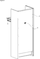
- Figure 1 - is the front view of a plant cultivation cabinet.
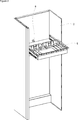
- Figure 2 - is the perspective view of the body, the unit and the bracket in an embodiment of the present invention.
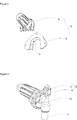
- Figure 3 - is the perspective view of the connection mechanism, the bracket and the bracket bearing in an embodiment of the present invention.
- Figure 4 - is the perspective view of the connection mechanism, the bend and the male component in an embodiment of the present invention.
- Figure 5 - is the perspective view of the body, the unit and the bracket bearing in an embodiment of the present invention.
- Figure 6 - is the perspective view of the tray, the unit and the female component in an embodiment of the present invention.
- Figure 7 - is the perspective view of the tray and the housing in an embodiment of the present invention.
- the plant cultivation cabinet (1) comprises
- the units (5) are placed into the plant cultivation cabinet (1) so as to cultivate plants in the body (2).
- the number and dimensions of the units (5) can be changed according to the dimensions of the body (2) and to the needs of the user.
- the trays (4) are placed onto the units (5).
- the plant cultivation cabinet (1) comprises a liquid receptacle positioned therein.
- the liquid in the liquid receptacle is delivered to the tray (4) by means of a pump in case the humidity of the mixture such as peat, etc. that is placed into the tray (4) and that enables the plants to take root and grow decreases below a value predetermined by the producer.
- the pumped liquid moisturizes the mixture in the tray (4) with perforated base and provides the growth of the plants.
- the excess liquid passes through the holes of the tray (4) to be collected in the unit (5).
- the rear side of the base of the unit (5) is at a lower level than the front side thereof relative to a (y) axis extending in the horizontal direction with respect to the door (3) plane.
- the excess liquid is collected at the rear side of the unit (5).
- the plant cultivation cabinet (1) of the present invention comprises a connection mechanism (10) having a bracket (8) wherein the male component (7) is fixed and wherein the female component (6) is fitted when the unit (5) is placed into the body (2), and a bracket bearing (9) that is arranged on the rear wall of the body (2) and that enables the bracket (8) to move therein in a (z) axis extending in the perpendicular direction and/or in a (y) axis extending in the vertical direction and/or an (x) axis extending in the horizontal direction relative to the door (3) plane.
- the units (5) can move in a (z) axis extending in the perpendicular direction relative to the door (3) plane.
- the user wants to harvest the products cultivated in the tray (4) or wants to sow plants into the tray (4), he/she pulls the unit (5) towards himself/herself.
- the female component (6) on the unit (5) and the male component (7) on the bracket (8) at the rear wall of the body (2) are separated from each other.
- the free end of the bracket (8) catches the female component (6).
- the female component (6) and the male component (7) can engage with each other without any problems since the bracket (8) can move in the bracket bearing (9) in at least one axis.
- the plant cultivation cabinet (1) comprises the bracket (8) with one end being cylindrical and the other in the of a U.
- the male component (7) is located at the U-shaped end and the female component (6) is located at the other end that is cylindrical.
- the female component (6) can be more easily caught by the bracket (8).
- the plant cultivation cabinet (1) comprises the bracket bearing (9) having a U-shaped channel (11) wherein the U-shaped end of the bracket (8) is movably fitted.
- the U-shaped end of the bracket (8) can move in the channel (11) in all of the three axes.
- the plant cultivation cabinet (1) comprises a bend (12) that enables the bracket (8) and the male component (7) to be mounted to each other.
- ease of assembly is provided during production.
- the plant cultivation cabinet (1) comprises a housing (13) that is arranged at the rear wall of the unit (5) and that enables the female component (6) to be mounted onto the unit (5).
- the female component (6) can be easily mounted onto the rear wall of the unit (5).
- connection mechanism (10) composed of the bracket (8) and the bracket bearing (9)
- the female component (6) on the rear wall of the detachable units (5) and the male component (7) at the rear wall of the body (2) as the starting point of the water discharge line can engage with each other without any problems.
Landscapes
- Life Sciences & Earth Sciences (AREA)
- Environmental Sciences (AREA)
- Cultivation Receptacles Or Flower-Pots, Or Pots For Seedlings (AREA)
- Hydroponics (AREA)
Abstract
The present invention relates to a plant cultivation cabinet (1) comprising a body (2); a door (3) providing access into the body (2); a tray (4) with a perforated base, wherein the mixture for growing the plants to be cultivated is placed; a unit (5) that is suitable for receiving the tray (4), that can move in a (z) axis extending in the perpendicular direction relative to the door (3) plane and wherein the excess liquid remaining after being absorbed by the mixture is collected; a female component (6) that is disposed at the rear side of the unit (5) and that enables the excess liquid collected in the unit (5) to be discharged out of the unit (5), and a male component (7) that is disposed on the body (2) and that engages with the female component (6) when the unit (5) is placed into the body (2) so as to discharge the excess liquid.
Description
The present invention relates to a plant cultivation cabinet comprising a connection mechanism.
Healthy life trend becomes more popular with each passing day and the number of people following this trend gradually increases. One of the sub-branches of this trend is healthy diet. The number of practices that may be called "home farming" wherein the users cultivate the products they eat in a controlled environment in their houses increases with each passing day. In plant cultivation cabinets providing the performance of home farming practices, one of the most critical issues is the watering system. The watering system is composed of a plurality of fixed and movable connection elements. The female component on the units that can move forwards-backwards in the plant cultivation cabinet may not fully engage with the male component on the rear wall of the body due to production tolerances. In such a case, the watering system cannot fully perform its function.
The production process must be perfect in order to enable the male component and the female component to be perfectly aligned. The occurrence of this has a very low probability due to production tolerances. Therefore, in order to enable the female component at the back of the units and the male component at the rear wall of the body to be perfectly aligned, the female component of each unit and the male component require precision work and precise adjustments. This increases the production costs and causes customer dissatisfaction since the positions of the units in the plant cultivation cabinet cannot be changed. When a unit is mounted to the rack of another unit instead of its own rack predetermined by the producer as a result of precise production for each male and female component, problems arise in the water discharge system.
In the state of the art United States Patent Document No. US8549788B2, a hydroponic growing system is disclosed.
The aim of the present invention is the realization of a plant cultivation cabinet comprising a connection mechanism that enables the female component disposed on the unit that can move forwards-backwards and the male component disposed on the rear wall of the body to be engaged with each other without any problem.
The plant cultivation cabinet realized in order to attain the aim of the present invention, explicated in the first claim and the respective claims thereof, comprises a body; a door providing access into the body, and a tray wherein the mixture for growing the plants to be cultivated is placed. The trays are placed into units in the body, that can move relative to the body and the door. The units are placed into sliding racks. The unit is the receptacle wherein the excess liquid that passes through the holes of the tray and that is not absorbed by the mixture is collected. The plant cultivation cabinet furthermore comprises a female component that enables the excess liquid collected in the unit to be discharged out of the unit, and a male component that is disposed on the body and that engages with the female component when the unit is placed into the body so as to discharge the excess liquid.
The plant cultivation cabinet of the present invention comprises a connection mechanism having a bracket wherein the male component is fixed and wherein the female component is fitted when the unit is placed into the body, and a bracket bearing that is arranged on the rear wall of the body and that allows the bracket to be moved therein in each of the three axes.
In an embodiment of the present invention, the plant cultivation cabinet comprises the bracket with one end being cylindrical and the other in the of a U. In this embodiment, the male component is located at the U-shaped end and the female component is located at the other end that is cylindrical. Thus, ease of use is provided.
In an embodiment of the present invention, the plant cultivation cabinet comprises the bracket bearing having a U-shaped channel wherein the U-shaped end of the bracket is movably fitted. The depth of the channel is more than the thickness of the U-shaped end of the bracket.
In an embodiment of the present invention, the plant cultivation cabinet comprises a bend that enables the bracket and the male component to be mounted to each other.
In an embodiment of the present invention, the plant cultivation cabinet comprises a housing that is arranged at the rear wall of the unit and that enables the female component to be mounted onto the unit.
All the detachable units in the plant cultivation cabinet of the present invention can be used with all the racks. Thus, the need for predetermining the positions of the units by the producer is eliminated, increasing the customer satisfaction and decreasing production costs.
The model embodiments relating to a plant cultivation cabinet realized in order to attain the aim of the present invention are illustrated in the attached figures, where:
Figure 1 - is the front view of a plant cultivation cabinet.
Figure 2 - is the perspective view of the body, the unit and the bracket in an embodiment of the present invention.
Figure 3 - is the perspective view of the connection mechanism, the bracket and the bracket bearing in an embodiment of the present invention.
Figure 4 - is the perspective view of the connection mechanism, the bend and the male component in an embodiment of the present invention.
Figure 5 - is the perspective view of the body, the unit and the bracket bearing in an embodiment of the present invention.
Figure 6 - is the perspective view of the tray, the unit and the female component in an embodiment of the present invention.
Figure 7 - is the perspective view of the tray and the housing in an embodiment of the present invention.
The elements illustrated in the figures are numbered as follows:
- Plant cultivation cabinet
- Body
- Door
- Tray
- Unit
- Female component
- Male component
- Bracket
- Bracket bearing
- Connection mechanism
- Channel
- Bend
- Housing
The plant cultivation cabinet (1) comprises
- a body (2);
- a door (3) providing access into the body (2);
- a tray (4) with a perforated base, wherein the mixture for growing the plants to be cultivated is placed;
- a unit (5) that is suitable for receiving the tray (4), that can move in a (z) axis extending in the perpendicular direction relative to the door (3) plane and wherein the excess liquid remaining after being absorbed by the mixture is collected;
- a female component (6) that is disposed at the rear side of the unit (5) and that enables the excess liquid collected in the unit (5) to be discharged out of the unit (5), and
- a male component (7) that is disposed on the body (2) and that engages with the female component (6) when the unit (5) is placed into the body (2) so as to discharge the excess liquid.
The units (5) are placed into the plant cultivation cabinet (1) so as to cultivate plants in the body (2). The number and dimensions of the units (5) can be changed according to the dimensions of the body (2) and to the needs of the user. The trays (4) are placed onto the units (5). The plant cultivation cabinet (1) comprises a liquid receptacle positioned therein. The liquid in the liquid receptacle is delivered to the tray (4) by means of a pump in case the humidity of the mixture such as peat, etc. that is placed into the tray (4) and that enables the plants to take root and grow decreases below a value predetermined by the producer. The pumped liquid moisturizes the mixture in the tray (4) with perforated base and provides the growth of the plants. The excess liquid passes through the holes of the tray (4) to be collected in the unit (5). The rear side of the base of the unit (5) is at a lower level than the front side thereof relative to a (y) axis extending in the horizontal direction with respect to the door (3) plane. Thus, the excess liquid is collected at the rear side of the unit (5). By means of the female component (6) and the male component (7) positioned at the rear wall of the unit (5) as a pipe with two ends open, the excess liquid is discharged from the unit (5) and delivered to the liquid receptacle.
The plant cultivation cabinet (1) of the present invention comprises a connection mechanism (10) having a bracket (8) wherein the male component (7) is fixed and wherein the female component (6) is fitted when the unit (5) is placed into the body (2), and a bracket bearing (9) that is arranged on the rear wall of the body (2) and that enables the bracket (8) to move therein in a (z) axis extending in the perpendicular direction and/or in a (y) axis extending in the vertical direction and/or an (x) axis extending in the horizontal direction relative to the door (3) plane.
The units (5) can move in a (z) axis extending in the perpendicular direction relative to the door (3) plane. When the user wants to harvest the products cultivated in the tray (4) or wants to sow plants into the tray (4), he/she pulls the unit (5) towards himself/herself. At this moment, the female component (6) on the unit (5) and the male component (7) on the bracket (8) at the rear wall of the body (2) are separated from each other. When the user replaces the unit (5), the free end of the bracket (8) catches the female component (6). In case the user cannot properly align the female component (6) and the male component (7), the female component (6) and the male component (7) can engage with each other without any problems since the bracket (8) can move in the bracket bearing (9) in at least one axis.
In an embodiment of the present invention, the plant cultivation cabinet (1) comprises the bracket (8) with one end being cylindrical and the other in the of a U. In this embodiment, the male component (7) is located at the U-shaped end and the female component (6) is located at the other end that is cylindrical. Thus, the female component (6) can be more easily caught by the bracket (8).
In an embodiment of the present invention, the plant cultivation cabinet (1) comprises the bracket bearing (9) having a U-shaped channel (11) wherein the U-shaped end of the bracket (8) is movably fitted. The U-shaped end of the bracket (8) can move in the channel (11) in all of the three axes.
In an embodiment of the present invention, the plant cultivation cabinet (1) comprises a bend (12) that enables the bracket (8) and the male component (7) to be mounted to each other. Thus, ease of assembly is provided during production.
In an embodiment of the present invention, the plant cultivation cabinet (1) comprises a housing (13) that is arranged at the rear wall of the unit (5) and that enables the female component (6) to be mounted onto the unit (5). By means of the housing (13), the female component (6) can be easily mounted onto the rear wall of the unit (5).
In the plant cultivation cabinet (1) of the present invention, by means of the connection mechanism (10) composed of the bracket (8) and the bracket bearing (9), the female component (6) on the rear wall of the detachable units (5) and the male component (7) at the rear wall of the body (2) as the starting point of the water discharge line can engage with each other without any problems.
Claims (5)
- A plant cultivation cabinet (1) comprising- a body (2);- a door (3) providing access into the body (2);- a tray (4) with a perforated base, wherein the mixture for growing the plants to be cultivated is placed;- a unit (5) that is suitable for receiving the tray (4), that can move in a (z) axis extending in the perpendicular direction relative to the door (3) plane and wherein the excess liquid remaining after being absorbed by the mixture is collected;- a female component (6) that is disposed at the rear side of the unit (5) and that enables the excess liquid collected in the unit (5) to be discharged out of the unit (5), and- a male component (7) that is disposed on the body (2) and that engages with the female component (6) when the unit (5) is placed into the body (2) so as to discharge the excess liquid,characterized by a connection mechanism (10) having a bracket (8) wherein the male component (7) is fixed and wherein the female component (6) is fitted when the unit (5) is placed into the body (2), and a bracket bearing (9) that is arranged on the rear wall of the body (2) and that enables the bracket (8) to move therein in a (z) axis extending in the perpendicular direction and/or in a (y) axis extending in the vertical direction and/or an (x) axis extending in the horizontal direction relative to the door (3) plane.
- A plant cultivation cabinet (1) as in Claim 1, characterized by the bracket (8) with one end being cylindrical and the other end in the form of a U.
- A plant cultivation cabinet (1) as in Claim 2, characterized by the bracket bearing (9) having a U-shaped channel (11) wherein the U-shaped end of the bracket (8) is movably fitted.
- A plant cultivation cabinet (1) as in any one of the above claims, characterized by a bend (12) that enables the bracket (8) and the male component (7) to be mounted to each other.
- A plant cultivation cabinet (1) as in any one of the above claims, characterized by a housing (13) that is arranged at the rear wall of the unit (5) and that enables the female component (6) to be mounted onto the unit (5).
Applications Claiming Priority (2)
| Application Number | Priority Date | Filing Date | Title |
|---|---|---|---|
| TRA2017/12808 | 2017-08-25 | ||
| TR2017/12808A TR201712808A2 (en) | 2017-08-25 | 2017-08-25 | PLANT GROWING UNIT WITH CONNECTION MECHANISM |
Publications (1)
| Publication Number | Publication Date |
|---|---|
| WO2019038013A1 true WO2019038013A1 (en) | 2019-02-28 |
Family
ID=63047349
Family Applications (1)
| Application Number | Title | Priority Date | Filing Date |
|---|---|---|---|
| PCT/EP2018/070186 Ceased WO2019038013A1 (en) | 2017-08-25 | 2018-07-25 | A plant cultivation cabinet comprising a connection mechanism |
Country Status (2)
| Country | Link |
|---|---|
| TR (1) | TR201712808A2 (en) |
| WO (1) | WO2019038013A1 (en) |
Citations (4)
| Publication number | Priority date | Publication date | Assignee | Title |
|---|---|---|---|---|
| WO2012153918A2 (en) * | 2011-05-09 | 2012-11-15 | Hong Kug Yeung | Home electronic appliance-type vegetable-growing machine |
| US8549788B2 (en) | 2012-03-06 | 2013-10-08 | Mb3, L.L.C. | Hydroponic growing system |
| EP3005861A1 (en) * | 2013-05-30 | 2016-04-13 | Haier Group Corporation | Vegetable freshness-preservation and growing case and piping connection control method for vegetable freshness-preservation and growing case |
| JP2016163596A (en) * | 2016-06-16 | 2016-09-08 | ユーテック株式会社 | Hydroponics apparatus |
-
2017
- 2017-08-25 TR TR2017/12808A patent/TR201712808A2/en unknown
-
2018
- 2018-07-25 WO PCT/EP2018/070186 patent/WO2019038013A1/en not_active Ceased
Patent Citations (4)
| Publication number | Priority date | Publication date | Assignee | Title |
|---|---|---|---|---|
| WO2012153918A2 (en) * | 2011-05-09 | 2012-11-15 | Hong Kug Yeung | Home electronic appliance-type vegetable-growing machine |
| US8549788B2 (en) | 2012-03-06 | 2013-10-08 | Mb3, L.L.C. | Hydroponic growing system |
| EP3005861A1 (en) * | 2013-05-30 | 2016-04-13 | Haier Group Corporation | Vegetable freshness-preservation and growing case and piping connection control method for vegetable freshness-preservation and growing case |
| JP2016163596A (en) * | 2016-06-16 | 2016-09-08 | ユーテック株式会社 | Hydroponics apparatus |
Also Published As
| Publication number | Publication date |
|---|---|
| TR201712808A2 (en) | 2019-03-21 |
Similar Documents
| Publication | Publication Date | Title |
|---|---|---|
| US10499574B2 (en) | Hydroponic plant grow cabinet | |
| US11464180B2 (en) | Vertical aeroponic plant growing enclosure | |
| KR101614925B1 (en) | plants cultivating apparatus for family use | |
| USD985301S1 (en) | Shelf for indoor plant cultivators | |
| CN102771374A (en) | Home electronic appliance-type vegetable-growing machine | |
| EP3481173A1 (en) | Plan cultivation container | |
| KR20170069059A (en) | Extendable Multi-stacked Seeding Pot | |
| CN214676835U (en) | Corn seedling cultivation device | |
| CN206402769U (en) | Seedling planting cabinet | |
| CN205179988U (en) | Hydroponic plant cultivation device | |
| CN220422583U (en) | Seedling culture device | |
| CN104620882B (en) | Modular seedling culture device | |
| KR101256044B1 (en) | Decorative flowerpot | |
| CN208691856U (en) | A kind of thermal-insulating type seedling raising greenhouse | |
| CN208836619U (en) | A kind of agricultural cultivation device convenient for plantation | |
| KR20210088278A (en) | Apparatus for cultivating plant | |
| KR200400137Y1 (en) | Cactus supporting apparatus | |
| CN217117035U (en) | Agricultural cultivation tray | |
| KR200449981Y1 (en) | Wall Mounted Decorative Flower Pot by Vacuum Absorption | |
| CN2415596Y (en) | Self-controlling cultivating receptacle embedded in the wall | |
| KR200395999Y1 (en) | water culture | |
| CN221488453U (en) | Circulation irrigation formula farming frame | |
| WO2018067089A2 (en) | Cultivator with improved air circulation | |
| CN216874162U (en) | Agricultural is with culture apparatus that grows seedlings | |
| CN219660512U (en) | Vegetable planting box |
Legal Events
| Date | Code | Title | Description |
|---|---|---|---|
| 121 | Ep: the epo has been informed by wipo that ep was designated in this application |
Ref document number: 18746895 Country of ref document: EP Kind code of ref document: A1 |
|
| NENP | Non-entry into the national phase |
Ref country code: DE |
|
| 122 | Ep: pct application non-entry in european phase |
Ref document number: 18746895 Country of ref document: EP Kind code of ref document: A1 |