WO2019035451A1 - 通信制御方法及び通信制御装置 - Google Patents
通信制御方法及び通信制御装置 Download PDFInfo
- Publication number
- WO2019035451A1 WO2019035451A1 PCT/JP2018/030229 JP2018030229W WO2019035451A1 WO 2019035451 A1 WO2019035451 A1 WO 2019035451A1 JP 2018030229 W JP2018030229 W JP 2018030229W WO 2019035451 A1 WO2019035451 A1 WO 2019035451A1
- Authority
- WO
- WIPO (PCT)
- Prior art keywords
- communication
- change
- communication path
- smf
- control
- Prior art date
- Legal status (The legal status is an assumption and is not a legal conclusion. Google has not performed a legal analysis and makes no representation as to the accuracy of the status listed.)
- Ceased
Links
Images


Classifications
-
- H—ELECTRICITY
- H04—ELECTRIC COMMUNICATION TECHNIQUE
- H04W—WIRELESS COMMUNICATION NETWORKS
- H04W36/00—Hand-off or reselection arrangements
- H04W36/12—Reselecting a serving backbone network switching or routing node
-
- H—ELECTRICITY
- H04—ELECTRIC COMMUNICATION TECHNIQUE
- H04W—WIRELESS COMMUNICATION NETWORKS
- H04W76/00—Connection management
-
- H—ELECTRICITY
- H04—ELECTRIC COMMUNICATION TECHNIQUE
- H04W—WIRELESS COMMUNICATION NETWORKS
- H04W92/00—Interfaces specially adapted for wireless communication networks
- H04W92/16—Interfaces between hierarchically similar devices
- H04W92/24—Interfaces between hierarchically similar devices between backbone network devices
Definitions
- the present invention relates to a communication control method and a communication control apparatus.
- next-generation mobile communication system (NextGen)
- NextGen Next-generation mobile communication system
- UPFs User Plane Functions
- handover when one user terminal (UE: User Equipment) is connected to a plurality of SMFs and UPFs, that is, a method of switching a communication path accompanying a change of a connection destination base station apparatus, etc. Is also being considered.
- Non-Patent Document 1 when the user terminal performs a handover, an Access and Mobility Management Function (AMF) that manages UPF and SMF (Session Management Function) processes the handover to the SMF. To indicate. Then, after the SMF communicates with the UPF for handover, the SMF responds to the AMF. AMF is shown to continue processing based on the response from SMF.
- AMF Access and Mobility Management Function
- the processing relating to the switching of the communication paths is performed for each of the plurality of communication paths. Therefore, the AMF instructs the processing related to the switching of the communication path to each of the plurality of SMFs corresponding to the plurality of UPFs. Further, it is assumed that the AMF continues processing after confirming all responses from each of the plurality of SMFs.
- the present invention has been made in view of the above, and a communication control method and communication capable of appropriately switching a communication path of a user terminal even when the user terminal is provided with a plurality of communication paths It aims at providing a control device.
- a communication control method provides a user terminal that transmits and receives user data via a plurality of communication paths by providing communication paths for a plurality of communication nodes.
- the communication control apparatus performs communication control related to a user terminal that transmits and receives user data through a plurality of communication paths by providing communication paths for a plurality of communication nodes.
- a communication control apparatus comprising: a change request acquisition unit acquiring a change request for requesting a change of the plurality of communication paths relating to the user terminal; and the change request acquired based on the change request acquisition unit.
- a change instruction transmission unit that transmits a change instruction signal that instructs a process related to a change in the communication path to a plurality of control nodes that individually control a plurality of communication nodes provided with a communication path, and the change instruction transmission
- a timer management unit for performing control to wait for a predetermined waiting time for reception of a response signal from the control node that has transmitted the change instruction signal in a control unit; Communication path change for completing the process related to the change of the communication path provided for the communication node controlled by the control node based on the response signal from the control node received during the standby time Part.
- the plurality of communication nodes individually provided with the communication path are controlled based on the change request for changing the plurality of communication paths relating to the user terminal.
- the control node After transmitting a change instruction signal instructing the control node to perform processing related to the change of the communication path, the control node waits for reception of a response signal from the control node for a predetermined time, and from the control node received during the waiting time The process related to the change of the communication path provided for the communication node controlled by the control node is completed based on the response signal of.
- the response is made without waiting for reception of the response signal even after the waiting time has elapsed.
- the processing related to the change of the communication path provided for the communication node controlled by the control node that has received the signal can be completed. Therefore, even when a plurality of communication paths are provided between the user terminal and the plurality of communication nodes, it is possible to appropriately switch the communication path of the user terminal.
- a communication control method and a communication control apparatus capable of appropriately switching the communication path of the user terminal even when the user terminal is provided with a plurality of communication paths.
- AMF AMF which functions as a communication control device. It is a figure explaining the function of AMF. It is a sequence diagram explaining the communication control method by a communication system. It is a sequence diagram explaining a series of processes in case a UE provides a communication path between 1st UPF. It is a figure explaining the example of the signal at the time of 2nd SMF notifying timer time to AMF. It is a figure explaining the hardware constitutions of AMF.
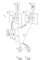
- FIG. 1 and 2 are diagrams for explaining the schematic configuration of a communication system 1 according to an embodiment of the present invention.
- FIG. 1 is a diagram for explaining a communication system 1 including an AMF 10 which functions as a communication control apparatus according to an embodiment of the present invention.
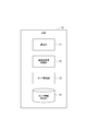
- FIG. 2 is a diagram for explaining the function of the AMF 10 functioning as a communication control device.
- a communication system 1 is a system for providing network service by data communication to a UE (User Equipment: user terminal) 60 which is a terminal device used by a user, in accordance with the definition in the architecture of NextGen. It is.
- the network service refers to a service using network resources such as communication service (exclusive line service etc.) and application service (moving image distribution, service using a sensor device such as an embedded device).
- some of the nodes included in the communication system 1 are provided on one or more slices that are virtualized networks that are logically generated on the network infrastructure.
- a slice is a virtualized network or service network logically created on the network infrastructure by virtually separating the link of the network device and the resources of the node and combining the separated resources, and the slices are resources They are separated and do not interfere with each other.
- the communication system 1 includes an Access and Mobility Management Function (AMF) 10, eNBs (eNodeBs) 21 and 22 (base station apparatus), a first SMF (Session Management Function) 31, a second SMF 32, and a first UPF A user plane function 41 and a second UPF 42 are included.
- the first UPF 41 can communicate with the V2X Server 51, which is a service server.
- the second UPF 42 is also communicable with the eMMB Server 52, which is also a service server.
- UE60 is implement
- AMF Access and Mobility Management Function
- eNBs eNodeBs
- base station apparatus base station apparatus
- SMF Session Management Function
- a second SMF 32 Session Management Function
- a user plane function 41 and a second UPF 42 are included.
- the first UPF 41 can communicate with the V2X Server 51, which is a service
- first SMF is indicated as “SMF 1” and “second SMF” is indicated as “SMF 2”.
- first UPF is indicated as “UPF1” and “second UPF” is indicated as “UPF2”.
- two eNBs are shown as “eNB1” and “eNB2”.
- the eNBs 21 and 22 are base station apparatuses for the UE 60 to perform communication connection by wireless communication.
- the eNBs 21 and 22 are respectively included in RAN (Regional Area Network) which is an access network used when the UE 60 performs communication connection.
- RAN Registered Area Network
- the areas covered by the eNBs 21 and 22 are respectively set, and the UE 60 can perform data communication using the communication system 1 by updating with the eNB of the area corresponding to the position of the own apparatus.
- the first UPF 41 and the second UPF 42 are communication nodes that respectively configure slices and transmit and receive user data with the UE 60.
- the first SMF 31 and the second SMF 32 are control nodes that form slices together with the first UPF 41 and the second UPF 42 and perform communication control on the first UPF 41 and the second UPF 42.
- the case is shown where the first SMF 31 and the first UPF 41 form a pair, and the second SMF 32 and the second UPF 42 form a pair, but one SMF performs communication control related to a plurality of UPFs. In some cases.
- the first SMF 31 and the first UPF 41 are provided on the same slice SL1
- the second SMF 32 and the second UPF 42 are provided on the same slice SL2. Accordingly, the UE 60 can communicate with the slice SL1 or the slice SL2 via the eNB (eNB21 or eNB22).
- the eNB eNB21 or eNB22
- the AMF 10 is a slice connection server that performs communication connection control between the slice and the UE 60.
- the AMF 10 has a function as a communication control device in the communication system 1 described in the present embodiment.
- the V2X (vehicle to X) Server 51 and the eMMB Server 52 are both service servers for providing specific services. Although the service server is provided according to the type of service to be provided, FIG. 1 shows the above two service servers as an example.
- the network service is provided to the UE 60 by assigning the service to a slice which is a virtualization network.
- Network slice control technology based on slice selection technology using DCN (Dedicated Core Network) and virtualization technology such as NFV (Network Function Virtualisation) / SDN (Software Defined Network) for creation and management of slices for each service Can be realized using DCN (Dedicated Core Network) and virtualization technology such as NFV (Network Function Virtualisation) / SDN (Software Defined Network) for creation and management of slices for each service Can be realized using DCN (Dedicated Core Network) and virtualization technology such as NFV (Network Function Virtualisation) / SDN (Software Defined Network) for creation and management of slices for each service Can be realized using DCN (Dedicated Core Network) and virtualization technology such as NFV (Network Function Virtualisation) / SDN (Software Defined Network) for creation and management of slices for each service Can be realized using DCN (Dedicated Core Network) and virtualization technology such as NFV (Network Function Virtualisation) / SDN (Software Defined Network) for creation and management of slices for each service Can be realized using DCN (Dedicated Core Network) and
- the slice control architecture utilizing NFV and SDN consists of a physical / virtual resource layer that composes a network such as a physical server and transport switch, and a network slice that has the necessary function set for providing services on physical / virtual resources.
- the configuration includes a virtual network layer to be configured, and a service instance layer that is the highest layer and manages service instances provided to end users.
- the physical / virtual resource layer is managed by, for example, a virtualized infrastructure manager (VIN) including an SDN-C (SDN controller).
- VIN virtualized infrastructure manager
- SDN-C SDN controller
- the virtual network layer is managed by, for example, VNFM (Virtual Network Function Manager) and NFVO (NFV Orchestrator) for each network slice.
- requirements of service instances in the service instance layer are monitored and guaranteed by an OSS / BSS (Operation Support System / Business Support System).
- Physical / virtual resource layer allocation is performed by slicing of the network by SDN-C and slicing of server resources by VIM, and a function set is arranged on the allocated resource slices by VNGFM and NFVO.
- the OSS / BSS monitors the network slice created in this way. As a result, slices corresponding to the service are created and managed.
- each slice SL1 and SL2 may be configured to include nodes different from the SMF and the UPF.
- the UE 60 is connected to a plurality of slices SL1 and SL2 to use a plurality of network services. Specifically, the UE 60 establishes a communication path R1 (bearer) with the first UPF 41 of the slice SL1 via the eNB 21, and performs data communication with the V2X Server 51. Further, a communication path R2 (bearer) is provided between the second UPF 42 of the slice SL2 via the eNB 21 and data communication is performed with the eMMB server 52.
- a communication path R1 (bearer) with the first UPF 41 of the slice SL1 via the eNB 21, and performs data communication with the V2X Server 51.
- a communication path R2 (bearer) is provided between the second UPF 42 of the slice SL2 via the eNB 21 and data communication is performed with the eMMB server 52.
- the UE 60 moves and the eNB with which the UE 60 performs communication connection is changed from eNB21 to eNB22.
- the communication path when the UE 60 uses the network service also needs to be changed from the communication paths R1 and R2 via the eNB 21 to the communication path via the eNB 22. Therefore, the eNB 22 transmits, to the AMF 10 that performs communication connection control between the slice and the UE 60, a Path Switch Request that requests a process of handover accompanying the movement of the UE 60. In FIG. 1, this request is shown as "1. Path Switch".
- the first SMF 31 that performs communication control related to the first UPF 41 provided with the communication channel R1 and the communication channel A Path Switch Request for requesting a handover process is transmitted to the second SMF 32 that performs communication control related to the second UPF 42 in which R2 is provided.
- this request is shown as "2. Path Switch” and "3. Path Switch”.
- the first SMF 31 and the second SMF 32 by performing communication with the UPF based on these instructions, after performing the desired processing in the first UPF 41 and the second UPF 42, processing corresponding to the request is performed on the AMF 10 Send a response signal (ACK) to notify that.
- ACK response signal
- the AMF 10 when receiving the responses from the first SMF 31 and the second SMF 32 corresponding to the communication paths R1 and R2 related to the UE 60, the AMF 10 performs processing of the latter stage, that is, a response to the eNB 22. This is the conventional handover process.
- the second SMF 32 sends a response signal (ACK) to the AMF 10 for some reason such as a failure.
- ACK response signal
- the processing of the latter stage is performed on the premise that the AMF 10 receives all the response signals from the first SMF 31 and the second SMF 32 corresponding to the communication paths R1 and R2 related to the UE 60. Therefore, as described above, when a state in which the response signal from the second SMF 32 can not be received occurs, the subsequent processing by the AMF 10 is not executed.
- both of the communication paths R1 and R2 are A situation occurs in which no handover is performed. That is, there is a possibility that the processing relating to the handover may not be appropriately performed even for the first SMF 31 and the first UPF 41 that should be operating normally.
- the AMF 10 waits for reception of response signals from a plurality of SMFs using a timer for a predetermined time, and based on the response signals from the SMF received within the standby time, It is characterized by performing processing. With such a configuration, it is possible to execute the process related to the handover in the latter stage for the one in which the response signal from the SMF is appropriately transmitted and received by the AMF 10. On the other hand, with regard to the communication path provided in the UPF controlled by the SMF controlled by the AMF 10, which can not confirm the response signal, the processing in the latter stage related to the handover can not be performed.
- processing related to handover is performed for communication paths related to SMF and UPF that are operating normally
- processing related to handover is performed for communication paths related to SMF and UPF that may not operate normally.
- the UE 60 is provided with a plurality of communication paths so as not to perform it, it is possible to appropriately perform the handover related to each communication path.
- the AMF 10 includes a communication unit 11 (a change request acquisition unit, a change instruction transmission unit), and a communication path change processing unit 12 (a change instruction transmission unit, a change process). Unit, a timer management unit 13, and a timer information holding unit 14.
- the communication unit 11 has a communication function for performing communication connection control between the slice and the UE 60. Therefore, a function as a change request acquisition unit that acquires a change request related to a change in the communication path of the UE 60, and a change instruction transmission unit that transmits a change instruction signal to the SMF as a control node based on the change request.
- a function of The AMF 10 communicates with the eNBs 21 and 22, the first SMF 31, and the second SMF 32 to transmit and receive information necessary for communication connection control.
- the communication unit 11 also has a function of communicating with other nodes not included in the communication system 1.
- the communication path change processing unit 12 has a function of performing processing related to the change of the communication path.
- the channel change processing unit 12 transmits an instruction relating to the handover to the SMF via the communication unit 11, and then uses the timer managed by the timer management unit 13 to receive the response signal from the SMF for a predetermined time. After waiting, the processing of the subsequent stage is advanced based on the presence or absence of reception of the response signal. That is, the communication path change processing unit 12 has a function as a change instruction transmission unit that transmits a change instruction signal to the SMF as the control node based on the change request. Further, the communication path change processing unit 12 is a communication path change unit that completes the process related to the change of the communication path provided for the UPF as the communication node controlled by the SMF based on the response signal from the SMF. It has a function.
- the timer management unit 13 has a function of managing a timer when waiting for a response signal from the SMF.
- the timer managed by the timer management unit 13 manages a standby time for waiting for reception of the response signal from the SMF.
- the waiting time managed by the timer may be set for each SMF with which the AMF 10 communicates for communication control, or may be set collectively instead of each SMF.
- the operation start (management start of standby time) and end of the timer in the timer management unit 13 are performed based on the instruction of the communication path change processing unit 12. That is, the timer management unit 13 has a function as a timer management unit that performs management of waiting for reception of a response signal from the SMF as a control node that has transmitted the change instruction signal and waiting for a predetermined standby time.
- the timer information holding unit 14 has a function of holding information related to the timer. When different standby times are set for each SMF, the timer information holding unit 14 stores information for specifying the standby time in association with the information for specifying the SMF. Then, based on the instruction of the communication path change processing unit 12, information related to the waiting time corresponding to the SMF to be awaited for reception of the response signal is extracted and managed as a timer in the timer management unit 13.
- the AMF 10 holds information relating to the waiting time for waiting for reception of the response signal from the SMF, and while the timer management unit 13 counts this waiting time, reception of the response signal from the SMF is performed. stand by.
- the waiting time may be set collectively instead of each SMF, but may be set for each SMF based on, for example, the physical distance between the AMF 10 and the SMF.
- the AMF 10 In order for the AMF 10 to wait for reception of the response signal from the SMF, that is, to count the waiting time corresponding to the SMF in the timer management unit 13, it is necessary for the AMF 10 to grasp the waiting time corresponding to the target SMF. is there. Details of the method of grasping the waiting time corresponding to the SMF in the AMF 10 will be described later.
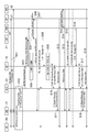
- the UE 60 provides communication paths (PDU Session ID # 1 and PDU Session ID # 2) between the first UPF 41 and the second UPF 42 via the eNB 2 (S01). ).
- the eNB with which the UE 60 communicates is to be switched to the eNB 22.
- a process HO Preparation and Execution relating to preparation for handover is performed between the eNB 21 and the eNB 22 (S02).
- a communication channel change request (N2 Path Switch Request) is transmitted from the eNB 22 to the AMF 10, and is received by the communication unit 11 of the AMF 10 (S03: change request acquisition step).
- the communication channel change request information specifying the UPF or slice of the partner with whom the UE 60 has provided the communication channel (here, information specifying the first UPF 41 and the second UPF 42, or information specifying the slices SL1 and SL2) Is included.
- the communication path change processing unit 12 of the AMF 10 starts the process related to the communication path change based on the communication path change request received by the communication unit 11.
- the UE 60 requests the first SMF 31 and the second SMF 32, which are SMFs corresponding to the UPF for which the communication path is provided, to change the communication path including the information for specifying the eNB of the change destination A change instruction signal (N11 Message) to be transmitted is transmitted (S04: change instruction transmission step). Further, at this timing, the communication path change processing unit 12 of the AMF 10 starts management of timers related to the first SMF 31 and the second SMF 32 in the timer management unit 13 (S05: standby step). The timer management unit 13 acquires information on the standby time of the first SMF 31 and the second SMF 32 from the timer information holding unit 14 and starts timers for each.
- the process related to the change of the communication path is appropriately performed in the first SMF 31. That is, the first SMF 31 that has received the change instruction signal related to the change of the communication path transmits / receives a signal related to the change of the communication path (Session modification Req & Resp) to the first UPF 41 (S06). In addition, the first UPF 41 transmits and receives necessary information related to the change of the communication path with the eNBs 21 and 22 (S07).
- a response signal (N11 Message ACK) to the change instruction signal (N11 Message) for requesting a change of the communication path is transmitted from the first SMF 31 to the AMF 10, and the communication unit 11 of the AMF 10 receives this (S08).
- the second SMF 32 should also transmit a response signal.
- the response signal from the second SMF 32 can not be received by the AMF 10 for some reason, and the timer related to the second SMF 32 is expired (S 09). That is, even if the waiting time of the response signal from the second SMF 32 designated in advance has passed, the response signal from the second SMF 32 can not be received.
- the communication path change processing unit 12 of the AMF 10 continues the processing of the subsequent stage only for the communication path that has received the response signal (N11 Message ACK) to complete the communication path change processing.
- the communication path change processing unit 12 of the AMF 10 since the response signal from the first SMF 31 is received by the AMF 10, the communication path change processing unit 12 of the AMF 10 transmits the communication path related to the first SMF 31 from the eNB 22 to the AMF 10.
- a response signal (N2 Path Switch Request ACK) to the communication path change request (N2 Path Switch Request) is transmitted to the eNB 22 via the communication unit 11 (S10: communication path change step).
- the eNB 22 Based on the response signal, the eNB 22 transmits a signal (Release Resources) related to release of resources to the eNB 21 (S11: communication path change step). As a result, the communication path (PDU Session ID # 1) provided between the UE 60 and the first UPF 41 is changed to one via the eNB 22 (S12: communication path change step). On the other hand, at this stage, the communication path (PDU Session ID # 2) provided between the UE 60 and the second UPF 42 is in a state of passing through the eNB 21 and the eNB 22 (S13). That is, the data transmitted and received between the UE 60 and the second UPF 42 is in a state of passing through the eNB 21 and the eNB 22 in response to the movement of the UE 60.
- a signal Release Resources
- the process related to the change of the communication path is performed also in the second SMF 32 whose process has been delayed due to some circumstances. That is, in the second SMF 32 that has received the change instruction signal related to the change of the communication path, transmission / reception of a signal (Session modification Req & Resp) related to the change of the communication path is performed to the second UPF 42 (S14). It is assumed that transmission and reception of necessary information related to the change of the communication path are performed with S.22 (S15).
- a response signal (N11 Message ACK) to the change instruction signal (N11 Message) for requesting a change of the communication path is transmitted from the second SMF 32 to the AMF 10, and this is received by the communication unit 11 of the AMF 10 (S16).
- the communication path change processing unit 12 of the AMF 10 performs processing of the latter stage related to the change of the communication path based on the response signal from the second SMF 32 whose management by the timer is finished. Specifically, regarding the communication path related to the second SMF 32, the communication path change processing unit 12 of the AMF 10 responds to the request signal (N2 Path Switch Request) for the communication path change request transmitted from the eNB 22 to the AMF 10.
- the switch request ACK is transmitted to the eNB 22 via the communication unit 11 (S17: post-processing step).
- the eNB 22 transmits a signal (Release Resources) related to release of resources to the eNB 21 (S18: post-processing step).
- the communication path (PDU Session ID # 2) provided between the UE 60 and the second UPF 42 is changed to one via the eNB 22 (S19: post-processing step).
- the response signal is received from the second SMF 32 after the timer has expired.
- S16 the case where the process of the latter stage is performed and the process related to the change of the communication path is completed has been described.
- the second SMF 32 can not perform normal processing, for example, as in the case where the second SMF 32 fails, a response signal from the second SMF 32 to the AMF 10 may not be sent.
- the post-stage processing is continued only for the communication path that has received the response signal within a predetermined time.
- a timer for stopping processing may be separately provided for a time longer than the time set by the timer.
- the timer for stopping the process is activated.
- the timer for processing cancellation expires, that is, there is a communication path which can not receive the response signal from the SMF even if the waiting time set in advance for processing cancellation has passed.
- the communication path change processing unit 12 of the AMF 10 instructs each device (SMF, eNB) or the like related to the establishment of the communication path not to change the communication path but to release the communication path. It is good also as composition.
- each timer related to the establishment of the communication path is not provided without separately providing a timer for stopping the process and the like.
- the apparatus (SMF, eNB) or the like may be configured to perform the release step of performing the process related to the release of the communication path.
- the timer managed by the AMF 10 will be described.
- the AMF 10 holds information relating to the waiting time for waiting for reception of the response signal from the SMF, and while the timer management unit 13 counts this waiting time, reception of the response signal from the SMF is performed. stand by.
- the waiting time may be set not collectively for each SMF but collectively, but may be set for each SMF.
- there are several methods for grasping the waiting time corresponding to the target SMF there are several methods for grasping the waiting time corresponding to the target SMF. Here, four methods are illustrated and described.
- the AMF 10 there is a method in which an operator or an O & M (Operation and Management) system previously allocates a set value of a waiting time of a response signal.
- the assigned setting value is held in the timer information holding unit 14.
- information on standby time corresponding to all the SMFs that are likely to be subject to communication control by the AMF 10 is held in the timer information holding unit 14.
- the third method is to wait for the signal transmitted from the SMF to the AMF 10 in the process (PDF session establishment) of newly establishing a communication path using the SMF and UPF with the UE.
- the communication path is provided with the UE, handover may occur as the UE moves. Therefore, when the communication path is provided, the information regarding the standby time is notified from the SMF to the AMF 10, and the AMF 10 is configured to hold the information in the timer information holding unit 14, whereby the communication path is not provided on the AMF 10 side.
- SMF it is not necessary to hold information related to the waiting time, and the amount of information to be held can be reduced.
- FIG. 4 is a diagram for explaining a series of processing when the UE 60 provides the communication path R1 with the first UPF 41.
- the series of processes shown in FIG. 3 are basically determined by the architecture related to Next Gen. Further, FIG. 4 also shows PCF (Policy Control Function), UDM (Unified Data Management), and DN (Data Network) that perform processing related to authentication or registration related to the establishment of a communication path, but these nodes are known. Node.
- the UE 60 transmits a request for establishment of a communication path (PDU Session Establish Request) to the AMF 10 through the eNB (described as (R) AN in FIG. 4) (S21).
- the AMF 10 determines the SMF to be connected based on the request from the UE 60 (S22)
- the AMF 10 sends a processing request signal (Namf_PDUSession_CreateSMContext) relating to the establishment of the communication path to the SMF (here, the first SMF 31).
- Send (S23).
- the first SMF 31 transmits an authentication request signal (Nudm_SubscriberData_Get) to the UDM based on the processing request signal (S24).
- an authentication process (PDU Session authentication / authorization) related to the establishment of the communication path of the UE 60 is performed (S 25).
- the first SMF 31 takes the lead, and performs a series of processes related to establishing a communication path with the PCF and the first UPF 41 (S26).
- the first SMF 31 to the AMF 10 responds to the processing request signal (Namf_PDUSession_CreateSMContext) for establishing a communication path (Namf_PDUSession_CreateSMContext).
- information (N11 Response Timer) relating to the waiting time for the first SMF 31 can be transmitted from the first SMF 31 to the AMF 10 in association with the response signal.
- the timer information holding unit 14 holds the first SMF 31 in association with the information specifying the same. Thereby, in the AMF 10, it is possible to grasp the information related to the standby time for the first SMF 31.
- the AMF 10 transmits a signal relating to the establishment of the communication path to the (R) AN and the UE 60, and the setting related to the communication path on the UE 60 side is performed (S28).
- the AMF 10 transmits a signal relating to the establishment of the communication path to the (R) AN and the UE 60, and the setting related to the communication path on the UE 60 side is performed (S28).
- transmission of data from the UE 60 to the first UPF 41 becomes possible (S29).
- a signal relating to the establishment of the communication path is transmitted from the AMF 10 to the first SMF 31, and the setting relating to the communication path on the first UPF 41 side is performed (S30).
- S32 post-processing for establishing a communication path is performed (S32), and a communication path between the UE 60 and the first UPF 41 is established.
- the SMF when performing the process of opening the communication path related to the UE 60, the SMF can notify the AMF 10 of information related to the standby time of the first SMF 31.
- the signal (Namf_PDUSession_CreateSMContextResponse: S27) described above is a signal different from the first SMF 31 to the AMF 10, the information related to the waiting time of the first SMF 31 is attached and transmitted. be able to.
- the signal may be transmitted together with information (N11 Response Timer) related to the waiting time for the first SMF 31.
- the fourth method for grasping the standby time corresponding to the target SMF is to notify the information related to the standby time from the SMF to the AMF 10 while performing a series of processes related to the change of the communication path of the UE 60. It is something to do.
- the series of processes related to the change of the communication path of the UE 60 are as described with reference to FIG. 3, but before the timer management unit 13 of the AMF 10 starts the timer (S05), the AMF 10 sends the first SMF 31 and the second SMF 32 A change instruction signal (N11 Message) is transmitted (S04).
- the configuration in which the information related to the own node is notified to the AMF 10 from the SMF that has received the change instruction signal can realize the configuration in which the information on the standby time is notified to the AMF 10.
- the second SMF 32 transmits information (N11 interface establishment) related to its own node to the AMF 10 ( S41) Configure.
- This signal is a signal added to the transmission and reception of the information shown in FIG. By adding such a signal, it becomes possible to notify the AMF 10 of information related to the standby time from the SMF while performing a series of processes related to the change of the communication path of the UE 60.
- various methods can be set for holding information related to the SMF standby time in the AMF 10. Therefore, the setting can be appropriately changed based on the device configuration and the like in the communication system 1.
- the communication control method is a user terminal (UE60) that transmits and receives user data via a plurality of communication paths by providing a communication path for each of a plurality of communication nodes (UPFs).
- SMF control nodes
- the AMF 10 which is a communication control apparatus according to an embodiment of the present invention, provides a communication path for each of a plurality of communication nodes (UPFs), thereby transmitting and receiving user data via a plurality of communication paths (a user terminal A communication control apparatus that performs communication control according to UE 60), and acquires in the change request acquisition unit, the communication unit 11 as a change request acquisition unit that acquires a change request that requests change of a plurality of communication paths related to a user terminal A change instruction signal for instructing a plurality of control nodes (SMF) individually controlling a plurality of communication nodes (UPFs) provided with communication paths based on the request for change to perform processing related to the change of the communication paths
- Communication unit 11 and communication path change processing unit 12 as a change instruction transmission unit to transmit, and reception of a response signal from a control node that has transmitted a change instruction signal in the change instruction transmission unit For the communication node controlled by the control node based on the response signal from the control node received during the standby time
- the plurality of communication nodes (UPFs) provided with the communication paths are individually provided based on the change request for requesting the change of the plurality of communication paths related to the user terminal (UE).
- UE user terminal
- a change instruction signal instructing a process related to the change of the communication path to a plurality of control nodes (SMF) to control
- it waits for reception of a response signal from the control node (SMF) for a predetermined time, and the standby Based on the response signal from the control node received during the time, the process related to the change of the communication path provided for the communication node (UPF) controlled by the control node is completed.
- the process related to the change of the communication path provided for the communication node controlled by the control node is completed.
- the method may further include a post-processing step.
- release processing is performed on a communication path provided for a communication node that controls a control node that can not receive a response signal during a predetermined period after the standby step. it can.
- the communication path itself can be opened. Therefore, the communication control device can be prevented from waiting for reception of the response signal from the control node that can not transmit the response signal.
- it is possible to open a communication path which can not perform processing relating to the change of the communication path it is possible to preferably release the resource used to provide the communication path.
- the communication path provided for the communication node controlled by the control node that can not receive the response signal during the waiting step may further include an opening step for opening the communication path.
- the communication path itself can be opened. Therefore, the communication control device can be prevented from waiting for reception of the response signal from the control node that can not transmit the response signal.
- it is possible to open a communication path which can not perform processing relating to the change of the communication path it is possible to preferably release the resource used to provide the communication path.
- the timing for opening the communication path is earlier than in the case where the post-processing step is provided. Therefore, the time required to start the release process of the resource is shortened, and the release of the resource is performed more quickly.
- the predetermined waiting time can be set for each control node.
- the control node having a large physical distance with respect to the communication control apparatus or the processing time required to transmit the response signal becomes longer. If there is a control node that knows in advance, appropriate waiting time can be assigned according to the status of these control nodes, and communication control related to the change of the communication path using the waiting time It can be suitably performed.
- the present invention is not limited to the above-mentioned embodiment.
- the communication control method according to the switching of the communication channel described above has an operation different from handover (for example, radio wave
- the present invention can also be applied to the change of the communication path triggered by the switching of the base station or the restart of the mobile station according to the quality and the congestion situation.
- control node and the communication node (UPF) are assigned to the same slice.
- these nodes may be assigned to different slices.
- control node and the communication node may be realized by a server device or the like that is not assigned to a slice.
- control node and the communication node may be realized by an integrated device or the like.
- the communication control device may also be realized by combining a plurality of devices.
- each functional block is not particularly limited. That is, each functional block may be realized by one physically and / or logically coupled device, or directly and / or indirectly two or more physically and / or logically separated devices. It may be connected by (for example, wired and / or wireless) and realized by the plurality of devices.
- the AMF 10 or the like as the communication control device in one embodiment of the present invention may function as a computer that performs processing according to the communication control method of the present invention.
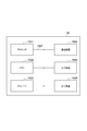
- FIG. 6 is a diagram showing an example of the hardware configuration of the AMF 10 according to an embodiment of the present invention.
- the above-described AMF 10 may be physically configured as a computer device including a processor 1001, a memory 1002, a storage 1003, a communication device 1004, an input device 1005, an output device 1006, a bus 1007 and the like.
- the term “device” can be read as a circuit, a device, a unit, or the like.
- the hardware configuration of the AMF 10 as a communication control device may be configured to include one or more of the devices shown in the figure, or may be configured without some devices.
- Each function in the AMF 10 causes the processor 1001 to perform an operation by reading predetermined software (program) on hardware such as the processor 1001, the memory 1002, etc., communication by the communication device 1004, data in the memory 1002 and the storage 1003 This is realized by controlling the reading and / or writing of
- the processor 1001 operates, for example, an operating system to control the entire computer.
- the processor 1001 may be configured by a central processing unit (CPU: Central Processing Unit) including an interface with a peripheral device, a control device, an arithmetic device, a register, and the like.
- CPU Central Processing Unit
- the above-described baseband signal processing unit 104, call processing unit 105, and the like may be realized by the processor 1001.
- the processor 1001 reads a program (program code), a software module or data from the storage 1003 and / or the communication device 1004 to the memory 1002, and executes various processing according to these.
- a program a program that causes a computer to execute at least a part of the operations described in the above embodiments is used.
- the communication path change processing unit 12 of the AMF 10 may be realized by a control program stored in the memory 1002 and operated by the processor 1001, or may be realized similarly for other functional blocks.
- the various processes described above have been described to be executed by one processor 1001, but may be executed simultaneously or sequentially by two or more processors 1001.
- the processor 1001 may be implemented by one or more chips.
- the program may be transmitted from the network via a telecommunication line.
- the memory 1002 is a computer readable recording medium, and includes, for example, at least one of a ROM (Read Only Memory), an EPROM (Erasable Programmable ROM), an EEPROM (Electrically Erasable Programmable ROM), and a RAM (Random Access Memory). May be
- the memory 1002 may be called a register, a cache, a main memory (main storage device) or the like.
- the memory 1002 can store a program (program code), a software module, and the like that can be executed to implement the communication control method according to an embodiment of the present invention.
- the storage 1003 is a computer readable recording medium, and for example, an optical disc such as a CD-ROM (Compact Disc ROM), a hard disc drive, a flexible disc, a magneto-optical disc (eg, a compact disc, a digital versatile disc, a Blu-ray A (registered trademark) disk, a smart card, a flash memory (for example, a card, a stick, a key drive), a floppy (registered trademark) disk, a magnetic strip, and the like may be used.
- the storage 1003 may be called an auxiliary storage device.
- the above-mentioned storage medium may be, for example, a database including the memory 1002 and / or the storage 1003, a server or any other suitable medium.
- the communication device 1004 is hardware (transmission / reception device) for performing communication between computers via a wired and / or wireless network, and is also called, for example, a network device, a network controller, a network card, a communication module, or the like.
- the communication unit 11 or the like of the above-described AMF 10 may be realized by the communication device 1004.
- the input device 1005 is an input device (for example, a keyboard, a mouse, a microphone, a switch, a button, a sensor, and the like) that receives an input from the outside.
- the output device 1006 is an output device (for example, a display, a speaker, an LED lamp, etc.) that performs output to the outside.
- the input device 1005 and the output device 1006 may be integrated (for example, a touch panel).
- bus 1007 for communicating information.
- the bus 1007 may be configured by a single bus or may be configured by different buses among the devices.
- the AMF 10 is configured to include hardware such as a microprocessor, a digital signal processor (DSP), an application specific integrated circuit (ASIC), a programmable logic device (PLD), and a field programmable gate array (FPGA). Some or all of the functional blocks may be realized by the hardware. For example, processor 1001 may be implemented in at least one of these hardware.
- DSP digital signal processor
- ASIC application specific integrated circuit
- PLD programmable logic device
- FPGA field programmable gate array
- notification of information is not limited to the aspects / embodiments described herein, and may be performed in other manners.
- notification of information may be physical layer signaling (for example, Downlink Control Information (DCI), Uplink Control Information (UCI)), upper layer signaling (for example, Radio Resource Control (RRC) signaling, Medium Access Control (MAC) signaling, It may be implemented by broadcast information (MIB (Master Information Block), SIB (System Information Block)), other signals, or a combination thereof.
- RRC signaling may be referred to as an RRC message, and may be, for example, an RRC connection setup (RRC Connection Setup) message, an RRC connection reconfiguration (RRC Connection Reconfiguration) message, or the like.
- Each aspect / embodiment described in the present specification is LTE (Long Term Evolution), LTE-A (LTE-Advanced), SUPER 3G, IMT-Advanced, 4G, 5G, FRA (Future Radio Access), W-CDMA (Registered trademark), GSM (registered trademark), CDMA2000, UMB (Ultra Mobile Broadband), IEEE 802.11 (Wi-Fi), IEEE 802.16 (WiMAX), IEEE 802.20, UWB (Ultra-Wide Band),
- the present invention may be applied to a system utilizing Bluetooth (registered trademark), other appropriate systems, and / or an advanced next-generation system based on these.
- the specific operation that is supposed to be performed by the base station in this specification may be performed by its upper node in some cases.
- the various operations performed for communication with the terminals may be the base station and / or other network nodes other than the base station (eg, It is clear that it may be performed by MME or S-GW etc but not limited to these).
- MME Mobility Management Entity
- S-GW Serving Mobility Management Entity
- Information and the like may be output from the upper layer (or lower layer) to the lower layer (or upper layer). Input and output may be performed via a plurality of network nodes.
- the input / output information or the like may be stored in a specific place (for example, a memory) or may be managed by a management table. Information to be input or output may be overwritten, updated or added. The output information etc. may be deleted. The input information or the like may be transmitted to another device.
- the determination may be performed by a value (0 or 1) represented by one bit, may be performed by a boolean value (Boolean: true or false), or may be compared with a numerical value (for example, a predetermined value). Comparison with the value).
- notification of predetermined information is not limited to what is explicitly performed, but is performed by implicit (for example, not notifying of the predetermined information) It is also good.
- Software may be called software, firmware, middleware, microcode, hardware description language, or any other name, and may be instructions, instruction sets, codes, code segments, program codes, programs, subprograms, software modules. Should be interpreted broadly to mean applications, software applications, software packages, routines, subroutines, objects, executables, threads of execution, procedures, functions, etc.
- software, instructions, etc. may be sent and received via a transmission medium.
- software may use a wireline technology such as coaxial cable, fiber optic cable, twisted pair and digital subscriber line (DSL) and / or a website, server or other using wireless technology such as infrared, radio and microwave When transmitted from a remote source, these wired and / or wireless technologies are included within the definition of transmission medium.
- wireline technology such as coaxial cable, fiber optic cable, twisted pair and digital subscriber line (DSL) and / or a website, server or other using wireless technology such as infrared, radio and microwave
- data, instructions, commands, information, signals, bits, symbols, chips etc may be voltage, current, electromagnetic waves, magnetic fields or particles, optical fields or photons, or any of these May be represented by a combination of
- the channels and / or symbols may be signals.
- the signal may be a message.
- the component carrier (CC) may be called a carrier frequency, a cell or the like.
- system and "network” as used herein are used interchangeably.
- radio resources may be indexed.
- a base station can accommodate one or more (e.g., three) cells (also called sectors). If the base station accommodates multiple cells, the entire coverage area of the base station can be divided into multiple smaller areas, each smaller area being a base station subsystem (eg, a small base station RRH for indoor use: Remote Communication service can also be provided by Radio Head.
- the terms “cell” or “sector” refer to a part or all of the coverage area of a base station and / or a base station subsystem serving communication services in this coverage.
- base station “eNB”, “cell” and “sector” may be used interchangeably herein.
- a base station may also be called in terms of a fixed station (Node station), NodeB, eNodeB (eNB), access point (access point), femtocell, small cell, and so on.
- the mobile station may be a subscriber station, a mobile unit, a subscriber unit, a wireless unit, a remote unit, a mobile device, a wireless device, a wireless communication device, a remote device, a mobile subscriber station, an access terminal, a mobile terminal, a wireless terminal, by those skilled in the art. It may also be called a terminal, a remote terminal, a handset, a user agent, a mobile client, a client, or some other suitable term.
- determining may encompass a wide variety of operations.
- “Judgment”, “decision” are, for example, judging, calculating, calculating, processing, processing, deriving, investigating, looking up (for example, a table) (Searching in a database or another data structure), ascertaining may be regarded as “decision”, “decision”, etc.
- “determination” and “determination” are receiving (e.g. receiving information), transmitting (e.g. transmitting information), input (input), output (output), access (accessing) (for example, accessing data in a memory) may be regarded as “judged” or “decided”.
- connection means any direct or indirect connection or coupling between two or more elements, It can include the presence of one or more intermediate elements between two elements that are “connected” or “coupled”.
- the coupling or connection between elements may be physical, logical or a combination thereof.
- the two elements are by using one or more wires, cables and / or printed electrical connections, and radio frequency as some non-limiting and non-exclusive examples. It can be considered “connected” or “coupled” to one another by using electromagnetic energy such as electromagnetic energy having wavelengths in the region, microwave region and light (both visible and invisible) regions.
- the phrase “based on” does not mean “based only on,” unless expressly stated otherwise. In other words, the phrase “based on” means both “based only on” and “based at least on.”
- any reference to an element using the designation "first,” “second,” etc. as used herein does not generally limit the quantity or order of those elements. These designations may be used herein as a convenient way of distinguishing between two or more elements. Thus, reference to the first and second elements does not mean that only two elements can be taken there, or that in any way the first element must precede the second element.
- each device described above may be replaced with a “unit”, a “circuit”, a “device” or the like.
- SYMBOLS 1 ... Communication system, 10 ... AMF, 11 ... Communication part, 12 ... Communication path change process part, 13 ... Timer management part, 14 ... Timer information holding part, 21, 22 ... eNB, 31 ... 1st SMF, 32 ... 2nd SMF , 41 ... 1st UPF, 42 ... 2nd UPF.
Landscapes
- Engineering & Computer Science (AREA)
- Computer Networks & Wireless Communication (AREA)
- Signal Processing (AREA)
- Mobile Radio Communication Systems (AREA)
Abstract
複数の通信ノード(UPF)に対してそれぞれ通信路を設けてユーザデータを送受信するユーザ端末(UE)(60)に係る通信制御を行う通信制御装置(AMF)(10)による通信制御方法であって、複数の通信路の変更要求を取得する変更要求取得ステップと、取得された変更要求に基づいて、通信路が設けられる複数の通信ノードを個別に制御する複数の制御ノード(SMF)に対して変更指示信号を送信する変更指示送信ステップと、変更指示信号を送信した制御ノードからの応答信号を所定の待機時間待機する待機ステップと、待機ステップの間に受信した制御ノードからの当該応答信号に基づいて、当該制御ノードが制御する通信ノードに対して設けられた通信路の変更に係る処理を完了する通信路変更ステップと、を有する。
Description
本発明は、通信制御方法及び通信制御装置に関する。
移動体通信システムの標準化プロジェクトである3GPP(Third Generation Partnership Project)では、移動体通信システムの次世代システム(NextGen)のアーキテクチャの標準化が進められている。次世代システムでは、1つの端末が複数のUPF(User Plane Function)との間で通信路を設けることが想定されている。非特許文献1では、1つのユーザ端末(UE:User Equipment)が複数のSMF,UPFと接続している際のハンドオーバ、すなわち、接続先の基地局装置の変更に伴う通信路の切り替えの手法等も検討されている。非特許文献1に記載された手法では、ユーザ端末がハンドオーバを行う際には、UPF及びSMF(Session Management Function)を管理するAMF(Access and Mobility Management Function)が、SMFに対してハンドオーバに係る処理を指示する。そして、SMFがUPFとの間でハンドオーバに係る通信を行った後に、SMFがAMFに対して応答する。AMFは、SMFからの応答に基づいて処理を継続することが示されている。
3GPP TS23.502
ここで、ユーザ端末が複数のUPFそれぞれとの間で複数の通信路を設けているとすると、通信路の切り替えに係る処理は、複数の通信路それぞれに対して行われる。したがって、AMFは、複数のUPFに対応する複数のSMFそれぞれに対して通信路の切り替えに係る処理が指示される。また、AMFは、複数のSMFそれぞれからの応答をすべて確認した後に処理を継続することが想定されている。
しかしながら、複数のSMFの一部から応答がない場合のことは想定されておらず、通信路の切り替えに係る制御を行う通信制御装置として機能するAMFにおいて、ユーザ端末の通信路の切り替えに係る処理が適切に行われない可能性がある。
本発明は上記を鑑みてなされたものであり、ユーザ端末が複数の通信路を設けている場合であっても、ユーザ端末の通信路の切り替えを適切に行うことが可能な通信制御方法及び通信制御装置を提供することを目的とする。
上記目的を達成するため、本発明の一形態に係る通信制御方法は、複数の通信ノードに対してそれぞれ通信路を設けることで、複数の前記通信路を介してユーザデータを送受信するユーザ端末に係る通信制御を行う通信制御装置による通信制御方法であって、前記ユーザ端末に係る複数の前記通信路の変更を要求する変更要求を取得する変更要求取得ステップと、前記変更要求取得ステップにおいて取得された前記変更要求に基づいて、前記通信路が設けられる複数の前記通信ノードを個別に制御する複数の制御ノードに対して、前記通信路の変更に係る処理を指示する変更指示信号を送信する変更指示送信ステップと、前記変更指示送信ステップにおいて前記変更指示信号を送信した前記制御ノードからの応答信号を所定の待機時間待機する待機ステップと、前記待機ステップの間に受信した前記制御ノードからの当該応答信号に基づいて、当該制御ノードが制御する前記通信ノードに対して設けられた前記通信路の変更に係る処理を完了する通信路変更ステップと、を有する。
また、本発明の一形態に係る通信制御装置は、複数の通信ノードに対してそれぞれ通信路を設けることで、複数の前記通信路を介してユーザデータを送受信するユーザ端末に係る通信制御を行う通信制御装置であって、前記ユーザ端末に係る複数の前記通信路の変更を要求する変更要求を取得する変更要求取得部と、前記変更要求取得部において取得された前記変更要求に基づいて、前記通信路が設けられる複数の前記通信ノードを個別に制御する複数の制御ノードに対して、前記通信路の変更に係る処理を指示する変更指示信号を送信する変更指示送信部と、前記変更指示送信部において前記変更指示信号を送信した前記制御ノードからの応答信号の受信を所定の待機時間待機する管理を行うタイマ管理部と、前記タイマ管理部により管理された待機時間の間に受信した前記制御ノードからの当該応答信号に基づいて、当該制御ノードが制御する前記通信ノードに対して設けられた前記通信路の変更に係る処理を完了する通信路変更部と、を有する。
上記の通信制御方法及び通信制御装置によれば、ユーザ端末に係る複数の前記通信路の変更を要求する変更要求に基づいて、通信路が設けられる複数の前記通信ノードを個別に制御する複数の制御ノードに対して、通信路の変更に係る処理を指示する変更指示信号を送信した後、制御ノードからの応答信号の受信を所定時間待機し、当該待機時間の間に受信した前記制御ノードからの当該応答信号に基づいて、当該制御ノードが制御する前記通信ノードに対して設けられた前記通信路の変更に係る処理が完了される。したがって、仮に、複数の制御ノードのうち、通信制御装置において待機時間の間に応答信号を受信できない制御ノードがある場合でも、待機時間が経過した後も応答信号の受信を待機することなく、応答信号を受信した制御ノードが制御する通信ノードに対して設けられた通信路の変更に係る処理を完了することができる。したがって、ユーザ端末と複数の通信ノードとの間で、複数の通信路が設けられている場合であっても、ユーザ端末の通信路の切り替えを適切に行うことができる。
本発明によれば、ユーザ端末が複数の通信路を設けている場合であっても、ユーザ端末の通信路の切り替えを適切に行うことが可能な通信制御方法及び通信制御装置が提供される。
以下、添付図面を参照して、本発明を実施するための形態を詳細に説明する。なお、図面の説明においては同一要素には同一符号を付し、重複する説明を省略する。
図1及び図2は、本発明の一実施形態に係る通信システム1の概略構成を説明する図である。図1は、本発明の一実施形態に係る通信制御装置として機能するAMF10を含む通信システム1について説明する図である。また、図2は、通信制御装置として機能するAMF10の機能について説明する図である。
本実施形態に係る通信システム1は、NextGenのアーキテクチャにおける規定に準拠して、ユーザが使用する端末装置であるUE(User Equipment:ユーザ端末)60に対して、データ通信によりネットワークサービスを提供するシステムである。ネットワークサービスとは、通信サービス(専用線サービス等)やアプリケーションサービス(動画配信、エンベデッド装置等のセンサ装置を利用したサービス)等のネットワーク資源を用いたサービスをいう。また、通信システム1に含まれるノードの一部は、ネットワークインフラ上に論理的に生成される仮想化ネットワークである一又は複数のスライス上に設けられる。スライスとは、ネットワーク装置のリンクとノードの資源を仮想的に切り分けて、切り分けた資源を結合し、ネットワークインフラ上に論理的に生成される仮想化ネットワーク又はサービス網であり、スライス同士は資源を分離しており、互いに干渉しないという特徴を有する。
図1に示すように、通信システム1は、AMF(Access and Mobility Management Function)10、eNB(eNodeB)21,22(基地局装置)、第1SMF(Session Management Function)31、第2SMF32、第1UPF(User Plane Function)41、第2UPF42を含んで構成される。また、第1UPF41は、サービスサーバであるV2X Server51との間で通信可能とされている。また、第2UPF42は、同じくサービスサーバであるeMMB Server52との間で通信可能とされている。UE60は、例えば、スマートフォン又はタブレット等の通信機能を有する端末装置により実現される。なお、図1では、「第1SMF」を「SMF1」と示し、「第2SMF」を「SMF2」と示している。同様に、「第1UPF」を「UPF1」と示し、「第2UPF」を「UPF2」と示している。また、2つのeNBを「eNB1」、「eNB2」として示している。
eNB21,22は、それぞれUE60が無線通信により通信接続するための基地局装置である。eNB21,22は、それぞれ、UE60が通信接続する際に用いるアクセスネットワークであるRAN(Regional Area Network)に含まれる。eNB21,22は、それぞれカバーするエリアが設定されていて、UE60は自機の位置に対応したエリアのeNBとの間で更新することにより、通信システム1を利用したデータ通信を行うことができる。
第1UPF41及び第2UPF42は、それぞれスライスを構成し、UE60との間でユーザデータを送受信する通信ノードである。
第1SMF31及び第2SMF32は、それぞれ第1UPF41、第2UPF42と共にスライスを構成し、これら第1UPF41、第2UPF42に対する通信制御を行う制御ノードである。なお、本実施形態では、第1SMF31と第1UPF41とが組になり、第2SMF32と第2UPF42とが組になっている場合を示しているが、1つのSMFが複数のUPFに係る通信制御を行う場合もある。
本実施形態では、第1SMF31と第1UPF41とが同じスライスSL1上に設けられ、第2SMF32と第2UPF42とが同じスライスSL2上に設けられている。したがって、UE60は、eNB(eNB21またはeNB22)を介して、スライスSL1またはスライスSL2と通信接続することができる。
AMF10は、スライスとUE60との通信接続制御を行うスライス接続サーバである。AMF10は、本実施形態で説明する通信システム1において、通信制御装置としての機能を有する。
V2X(vehicle to X) Server51及びeMMB Server52は、いずれも特定のサービスを提供するためのサービスサーバである。提供するサービスの種類に応じてサービスサーバが設けられるが、図1では一例として上記の2つのサービスサーバを示している。
通信システム1では、上述したように、仮想化ネットワークであるスライスに対してサービスを割り当てることで、UE60に対してネットワークサービスを提供する。
サービス毎のスライスの作成及び管理については、DCN(Dedicated Core Network)を用いたスライス選択技術、及び、NFV(Network Function Virtualisation)/SDN(Software Defined Network)などの仮想化技術に基づくネットワークスライス制御技術を用いて実現することができる。
NFV及びSDNを活用したスライス制御アーキテクチャは、物理サーバやトランスポートスイッチなどのネットワークを構成する物理/仮想資源層、物理/仮想資源上にサービスを提供するための必要な機能セットを有するネットワークスライスを構成する仮想ネットワーク層、及び、最上位層であってエンドユーザに提供されるサービスインスタンスを管理するサービスインスタンス層を含む。物理/仮想資源層は、例えば、SDN-C(SDN Controller)を含むVIN(Virtualized Infrastructure Manager)によって管理される。また、仮想ネットワーク層は、例えば、ネットワークスライス毎にVNFM(Virtual Network Function Manager)、NFVO(NFV Orchestrator)によって管理される。また、サービスインスタンス層におけるサービスインスタンスの要求条件は、OSS/BSS(Operation Support System/Business Support System)により監視され、保証される。
SDN-Cによるネットワークのスライシング及びVIMによるサーバ資源のスライシングによって、物理/仮想資源層の割り当てが行われ、VNGFM及びNFVOによって、割り当てられた資源スライス上に機能セットを配置する。そして、このようにして作成されたネットワークスライスについて、OSS/BSSが監視を行う。この結果、サービスに対応したスライスが作成及び管理される。
図1では、互いに独立するスライスSL1、SL2において、互いに異なるネットワークサービスを提供するとする。なお、複数のスライスにおいて同一のネットワークサービスが提供される構成であってもよい。また、1つのスライスに対して互いに異なるネットワークサービスを提供するノードが含まれる構成であってもよい。また、スライスSL1、SL2の定義を変更することで、各スライスSL1,SL2にSMF及びUPFとは異なるノードが含まれる構成としてもよい。
ここで、図1を参照しながら従来の通信システムにおける技術課題について説明する。図1に示す通信システム1では、UE60が複数のスライスSL1、SL2に接続して複数のネットワークサービスを利用していることを想定している。具体的には、UE60は、eNB21を介してスライスSL1の第1UPF41との間に通信路R1(ベアラ)を設け、V2X Server51との間でデータ通信を行っている。また、eNB21を介してスライスSL2の第2UPF42との間に通信路R2(ベアラ)を設け、eMMB Server52との間でデータ通信を行っている。
ここで、UE60が移動し、UE60が通信接続を行うeNBがeNB21からeNB22に変更したとする。この場合、UE60がネットワークサービスを利用する際の通信路も、eNB21を経由する通信路R1,R2からeNB22を経由する通信路に変更する必要がある。そのため、eNB22は、スライスとUE60との通信接続制御を行うAMF10に対して、UE60の移動に伴うハンドオーバの処理を要求するPath Switch Requestを送信する。図1中では、このリクエストを「1. Path Switch」として示している。
ハンドオーバの処理の要求を受けたAMF10は、UE60に係る通信路R1,R2の切り替えが必要であるから、通信路R1が設けられている第1UPF41に係る通信制御を行う第1SMF31、及び、通信路R2が設けられている第2UPF42に係る通信制御を行う第2SMF32に対して、ハンドオーバの処理を要求するPath Switch Requestを送信する。図1中では、このリクエストを「2. Path Switch」、「3.Path Switch」として示している。第1SMF31及び第2SMF32では、これらの指示に基づいてUPFと通信を行うことで、第1UPF41及び第2UPF42における所望の処理を行った後、それぞれAMF10に対して、リクエストに対する対応する処理が行われたことを通知する応答信号(ACK)を送信する。AMF10では、UE60に係る通信路R1,R2に対応する第1SMF31及び第2SMF32からの応答を受信すると、後段の処理、すなわち、eNB22に対する応答を行う。これが従来のハンドオーバの処理である。
ここで、故障等の何らかの事情により第2SMF32からAMF10に対して応答信号(ACK)が送信されない状態が発生したとする。この場合、AMF10では、図1に示すように、第1SMF31からの応答信号は受信済みであるが、第2SMF32からの応答信号は受信できない状態となる。従来のハンドオーバの処理では、AMF10が、UE60に係る通信路R1,R2に対応する第1SMF31及び第2SMF32からの応答信号をすべて受信することを前提として後段の処理が行われている。したがって、上記のように第2SMF32からの応答信号が受信できない状態が発生すると、AMF10による後段の処理が実行されない。そのため、従来のハンドオーバの処理によれば、AMF10において第1SMF31からの応答信号は受信している場合でも、第2SMF32からの応答信号を受信していない場合には、通信路R1,R2の両方のハンドオーバが実行されない状態が発生する。すなわち、正常に動作しているはずの第1SMF31及び第1UPF41についても、ハンドオーバに係る処理が適切に行われない可能性がある。
そこで、本実施形態に係る通信システム1では、AMF10において、タイマを用いて複数のSMFからの応答信号の受信を所定時間待機し、待機時間内に受信したSMFからの応答信号に基づいて後段の処理を行うことを特徴とする。このような構成とすることで、SMFからの応答信号が適切に送信されてAMF10において受信されたものについては、後段のハンドオーバに係る処理を実行することができる。一方、AMF10において応答信号を確認することができなかったSMFが制御するUPFにおいて設けられた通信路に関しては、ハンドオーバに係る後段の処理を行わない構成とすることができる。そのため、正常に動作しているSMF及びUPFに係る通信路についてはハンドオーバに係る処理を行う一方、正常に動作していない可能性のあるSMF及びUPFに係る通信路については、ハンドオーバに係る処理を行わない、というように、UE60が複数の通信路を設けている場合に、各通信路に係るハンドオーバを適切に行うことを可能としている。
このような構成を実現するために、図2に示すように、AMF10は、通信部11(変更要求取得部、変更指示送信部)と、通信路変更処理部12(変更指示送信部、変更処理部)と、タイマ管理部13と、タイマ情報保持部14と、を有する。
通信部11は、スライスとUE60との通信接続制御を行うための通信機能を有する。したがって、UE60の通信路の変更に係る変更要求を取得する変更要求取得部としての機能、及び、この変更要求に基づいて制御ノードとしてのSMFに対して変更指示信号を送信する変更指示送信部としての機能を有する。AMF10は、eNB21,22、第1SMF31、及び、第2SMF32との間通信を行い、通信接続制御に必要な情報の送受信を行う。また、通信部11は、通信システム1に含まれない他のノードとも通信を行う機能を有する。
通信路変更処理部12は、通信路の変更に係る処理を行う機能を有する。通信路変更処理部12は、SMFに対して通信部11を介してハンドオーバに係る指示を送信した後に、タイマ管理部13において管理するタイマを利用して、SMFからの応答信号の受信を所定時間待機した後に、応答信号の受信の有無に基づいて後段の処理を進める。すなわち、通信路変更処理部12は、変更要求に基づいて制御ノードとしてのSMFに対して変更指示信号を送信する変更指示送信部としての機能を有する。また、通信路変更処理部12は、SMFからの応答信号に基づいて、SMFが制御する通信ノードとしてのUPFに対して設けられた通信路の変更に係る処理を完了する通信路変更部としての機能を有する。
タイマ管理部13は、SMFからの応答信号を待機する際のタイマを管理する機能を有する。タイマ管理部13で管理されるタイマとは、SMFからの応答信号の受信を待機する待機時間を管理するものである。タイマにより管理される待機時間は、AMF10が通信制御のために通信を行うSMF毎に定められていてもよいし、SMF毎ではなく一括して設定されてもよい。タイマ管理部13でのタイマの動作開始(待機時間の管理開始)及び終了は、通信路変更処理部12の指示に基づいて行われる。すなわち、タイマ管理部13は、変更指示信号を送信した制御ノードとしてのSMFからの応答信号の受信を所定の待機時間待機する管理を行うタイマ管理部としての機能を有する。
タイマ情報保持部14は、タイマに係る情報を保持する機能を有する。SMF毎に互いに異なる待機時間が設定されている場合、タイマ情報保持部14において、SMFを特定する情報に対応付けて、待機時間を特定する情報を記憶する。そして、通信路変更処理部12の指示に基づいて、応答信号の受信の待機対象となるSMFに対応した待機時間に係る情報を取り出し、タイマ管理部13においてタイマとして管理する。
AMF10では、上記したようにSMFからの応答信号の受信を待機する待機時間に係る情報を保持し、タイマ管理部13においてこの待機時間をカウントしている間は、SMFからの応答信号の受信を待機する。待機時間は、SMF毎ではなく一括して設定することもできるが、例えば、AMF10とSMFとの物理的距離等に基づいて、SMF毎に設定してもよい。AMF10においてSMFからの応答信号の受信を待機する、すなわちタイマ管理部13において当該SMFに対応した待機時間をカウントするためには、対象となるSMFに対応する待機時間をAMF10側で把握する必要がある。AMF10においてSMFに対応する待機時間を把握する方法の詳細については後述する。
次に、通信システム1による通信制御方法、すなわち、UE60がハンドオーバした際の通信路の切り替え方法について、図3を参照しながら説明する。
前提として、図1に示すようにUE60は、eNB2を介して、第1UPF41及び第2UPF42との間にそれぞれ通信路(PDU Session ID#1、PDU Session ID#2)を設けているとする(S01)。ここで、UE60の移動に伴い、UE60が通信を行うeNBをeNB22へ切り替えることになったとする。この場合、まず、eNB21とeNB22との間で、ハンドオーバの準備に係る処理(HO Preparation and Execution)が行われる(S02)。その後、eNB22からAMF10に対して通信路の変更要求(N2 Path Switch Request)が送信され、AMF10の通信部11により受信される(S03:変更要求取得ステップ)。通信路の変更要求には、UE60が通信路を設けている相手のUPF又はスライスを特定する情報(ここでは、第1UPF41及び第2UPF42を特定する情報、又は、スライスSL1,SL2を特定する情報)が含まれる。AMF10の通信路変更処理部12では、通信部11が受信した通信路の変更要求に基づいて、通信路変更に係る処理を開始する。まず、通信部11を介して、UE60が通信路を設けているUPFに対応するSMFである第1SMF31及び第2SMF32に対して、変更先のeNBを特定する情報を含めた通信路の変更を要求する変更指示信号(N11 Message)を送信する(S04:変更指示送信ステップ)。また、このタイミングで、AMF10の通信路変更処理部12は、タイマ管理部13において、第1SMF31及び第2SMF32に係るタイマの管理を開始する(S05:待機ステップ)。タイマ管理部13では、タイマ情報保持部14から第1SMF31及び第2SMF32についての待機時間に係る情報を取得し、それぞれについてのタイマを起動する。
次に、ここでは、第1SMF31では適切に通信路の変更に係る処理が行われたとする。すなわち、通信路の変更に係る変更指示信号を受信した第1SMF31では、第1UPF41に対して通信路の変更に係る信号(Session modification Req&Resp)の送受信を行う(S06)。また、第1UPF41は、eNB21,22との間で通信路の変更に係る必要な情報の送受信を行う(S07)。その後、第1SMF31からAMF10に対して、通信路の変更を要求する変更指示信号(N11 Message)に対する応答信号(N11 Message ACK)が送信され、AMF10の通信部11においてこれが受信される(S08)。
通常は、第2SMF32においても、第1SMF31での一連の処理(S06~S08)と同様の処理が行われる。したがって、AMF10のタイマ管理部13においてタイマを起動させている間に、第2SMF32からも応答信号が送信されるはずである。しかしながら、本実施形態では、何らかの事情により第2SMF32からの応答信号をAMF10において受信することができず、第2SMF32に係るタイマが切れてしまう(S09)とする。すなわち、予め指定された第2SMF32からの応答信号の待機時間を過ぎても、第2SMF32からの応答信号を受信できない状態となっている。
この場合、AMF10の通信路変更処理部12では、応答信号(N11 Message ACK)を受信した通信路についてのみ、後段の処理を継続して、通信路の変更処理を完了させる。図3に示す例では、第1SMF31からの応答信号はAMF10において受信しているので、AMF10の通信路変更処理部12は、第1SMF31に関係する通信路に関して、eNB22からAMF10に対して送信された通信路の変更要求(N2 Path Switch Request)に対する応答信号(N2 Path Switch Request ACK)を、通信部11を介してeNB22に対して送信する(S10:通信路変更ステップ)。この応答信号に基づいて、eNB22は、eNB21に対してリソースの開放に係る信号(Release Resources)を送信する(S11:通信路変更ステップ)。この結果、UE60と第1UPF41との間に設けられる通信路(PDU Session ID#1)は、eNB22を経由するものに変更される(S12:通信路変更ステップ)。一方、この段階では、UE60と第2UPF42との間に設けられる通信路(PDU Session ID#2)は、eNB21及びeNB22を経由する状態となっている(S13)。すなわち、UE60と第2UPF42との間での送受信されるデータは、UE60の移動に対応してeNB21及びeNB22を経由する状態となっている。
その後、何らかの事情により処理が遅れていた第2SMF32においても、通信路の変更に係る処理が行われたとする。すなわち、通信路の変更に係る変更指示信号を受信した第2SMF32では、第2UPF42に対して通信路の変更に係る信号(Session modification Req&Resp)の送受信が行われ(S14)、第2UPF42が、eNB21,22との間で通信路の変更に係る必要な情報の送受信を行ったとする(S15)。その後、第2SMF32からAMF10に対して、通信路の変更を要求する変更指示信号(N11 Message)に対する応答信号(N11 Message ACK)が送信され、AMF10の通信部11においてこれが受信された(S16)とする。
この場合、AMF10の通信路変更処理部12では、タイマでの管理が終了した第2SMF32からの応答信号に基づいて、通信路の変更に係る後段の処理を行う。具体的には、AMF10の通信路変更処理部12は、第2SMF32に関係する通信路に関して、eNB22からAMF10に対して送信された通信路の変更要求(N2 Path Switch Request)に対する応答信号(N2 Path Switch Request ACK)を、通信部11を介してeNB22に対して送信する(S17:後処理ステップ)。この応答信号に基づいて、eNB22は、eNB21に対してリソースの開放に係る信号(Release Resources)を送信する(S18:後処理ステップ)。この結果、UE60と第2UPF42との間に設けられる通信路(PDU Session ID#2)は、eNB22を経由するものに変更される(S19:後処理ステップ)。
なお、上記で説明した図3に示す処理では、タイマが切れた(所定の待機時間が経過した)後の第2SMF32に関係する通信路についても、タイマが切れた後に第2SMF32から応答信号を受信した場合(S16)には、後段の処理を行い、通信路の変更に係る処理を完了させる場合について説明した。しかしながら、例えば第2SMF32が故障した場合のように、第2SMF32が正常な処理を行うことができない場合には、第2SMF32からAMF10への応答信号が送られない可能性がある。したがって、AMF10では、複数の通信路の変更を行う場合に上記のタイマ管理部13において管理するタイマを用いて、所定の時間のうちに応答信号を受信した通信路に関してのみ後段の処理を継続する構成とした上で、例えば、タイマで設定される時間よりも長い時間の処理中止用のタイマを別途設けておく構成としてもよい。
この場合、例えば、タイマ管理部13においてSMFに関するタイマの起動(S05)と同時に、処理中止用のタイマを起動しておく。そして、処理中止用のタイマが切れる、すなわち、処理中止用に予め設定された待機時間を経過しても、SMFからの応答信号を受信できていない通信路がある場合には、上述の後処理ステップの一環として、AMF10の通信路変更処理部12は、当該通信路の開設に関係する各装置(SMF、eNB)等に対して、当該通信路の変更ではなく当該通信路の開放を指示する構成としてもよい。
また、タイマ管理部13において管理するSMF毎のタイマ(又は、一括して設定するタイマ)が切れた場合には、処理中止用のタイマ等を別途設けることなく、通信路の開設に関係する各装置(SMF、eNB)等に対して、当該通信路の開放に係る処理を行う開放ステップを行う構成としてもよい。
ここで、AMF10において管理するタイマについて説明する。上記したように、AMF10ではSMFからの応答信号の受信を待機する待機時間に係る情報を保持し、タイマ管理部13においてこの待機時間をカウントしている間は、SMFからの応答信号の受信を待機する。待機時間は、SMF毎ではなく一括して設定することもできるが、SMF毎に設定することもしてもよい。AMF10において、対象となるSMFに対応する待機時間を把握する方法はいくつか挙げることができる。ここでは、4つの方法について例示して説明する。
第1の方法としては、AMF10において、オペレータまたはO&M(Operation and Management)システムにより、予め応答信号の待機時間の設定値を割り振っておく方法が挙げられる。この場合、割り振られた設定値は、タイマ情報保持部14に保持される。この場合、AMF10が通信制御する対象となる可能性のある全てのSMFに対応した待機時間の情報がタイマ情報保持部14に保持されることになる。
第2の方法としては、AMF10が通信制御する対象となる可能性のあるSMFが起動(Activate)して、SMFとAMF10との間で最初に通信を行う際に、SMFからAMF10に対して通知する方法が挙げられる。
第3の方法としては、UEとの間で、SMF・UPFを利用する通信路を新たに設ける処理を行う処理(PDF session establishment)の際に、SMFからAMF10に対して送信する信号に、待機時間に係る情報を含める方法が挙げられる。UEとの間で通信路を設けた場合、UEの移動に伴ってハンドオーバが発生する可能性がある。そこで、通信路を設けた際に、待機時間に係る情報をSMFからAMF10へ通知し、AMF10においてタイマ情報保持部14で保持する構成とすることで、AMF10側では、通信路が設けられていないSMFに関しては待機時間に係る情報を保持しなくてもよくなり、保持する情報量を削減することができる。
第3の方法に関して、図4を参照しながら説明する。図4は、UE60が第1UPF41との間で通信路R1を設ける場合の一連の処理を説明する図である。なお、この図3で示す一連の処理は、基本的にNext Genに係るアーキテクチャで定められているものである。また、図4では、通信路開設に係る認証又は登録等に係る処理を行うPCF(Policy Control Function)、UDM(Unified Data Management)、DN(Data Network)も示しているが、これらのノードは公知のノードである。
まず、UE60がeNB(図4では、(R)ANと記載している)を経てAMF10に対して通信路の開設要求(PDU Session Establish Request)を送信する(S21)。AMF10は、このUE60からの要求に基づいて、接続対象となるSMFを決定した後(S22)、当該SMF(ここでは、第1SMF31)に対して、通信路開設に係る処理要求信号(Namf_PDUSession_CreateSMContext)を送信する(S23)。第1SMF31は、この処理要求信号に基づいて、UDMに対して認証要求信号(Nudm_SubscriberData_Get)を送信する(S24)。これにより、UE60の通信路の開設に関連した認証処理(PDU Session authentication/authorization)を行う(S25)。その後、第1SMF31が主体となり、PCF及び第1UPF41との間で通信路開設に係る一連の処理を行う(S26)。
第1SMF31がPCF及び第1UPF41との間で通信路開設に係る一連の処理(S26)を行った後、第1SMF31からAMF10に対して、通信路開設に係る処理要求信号(Namf_PDUSession_CreateSMContext)に対する応答信号(Namf_PDUSession_CreateSMContextResponse)を送信する(S27)。ここで、この応答信号に対応付けて第1SMF31からAMF10に対して第1SMF31についての待機時間に係る情報(N11 Response Timer)を送信することができる。AMF10では、通信部11でこれを受信すると、第1SMF31を特定する情報に対応付けてタイマ情報保持部14において保持する。これにより、AMF10において、第1SMF31についての待機時間に係る情報を把握することができる。
その後、AMF10から(R)AN及びUE60に対して、通信路開設に係る信号を送信し、UE60側での通信路に係る設定を行う(S28)。この結果、UE60から第1UPF41へのデータの送信が可能となる(S29)。そして、AMF10から第1SMF31に対して通信路開設に係る信号を送信し、第1UPF41側での通信路に係る設定を行う(S30)。この結果、第1UPF41からUE60へのデータの送信が可能となる(S31)。その後、通信路開設に係る後処理を行い(S32)、UE60と第1UPF41との間の通信路が開設される。
このように、UE60に係る通信路を開設する処理を行う際に、第1SMF31についての待機時間に係る情報をSMFからAMF10に対して通知する構成とすることができる。なお、上記で説明した信号(Namf_PDUSession_CreateSMContextResponse:S27)とは異なる信号であっても、第1SMF31からAMF10に対して送信する信号であれば、第1SMF31についての待機時間に係る情報を添付して送信することができる。例えば、図3に示す例では、第1UPF41側での通信路に係る設定を行う(S30)際に、第1SMF31からAMF10に対して送信する信号がある(16.Nsmf_PDUSession_UpdateSMSContectResponse)。したがって、この信号に第1SMF31についての待機時間に係る情報(N11 Response Timer)を添えて送信する構成としてもよい。
AMF10において、対象となるSMFに対応する待機時間を把握する第4の方法は、UE60の通信路の変更に係る一連の処理を行う途中で、SMFからAMF10に対して待機時間に係る情報を通知するというものである。UE60の通信路の変更に係る一連の処理は、図3を参照しながら説明したとおりだが、AMF10のタイマ管理部13においてタイマを起動する(S05)前に、AMF10から第1SMF31及び第2SMF32に対して変更指示信号(N11 Message)を送信している(S04)。そこで、変更指示信号を受信したSMFからAMF10に対して、自ノードに係る情報を通知する構成とすることで、待機時間に関する情報をAMF10に対して通知する構成を実現することができる。具体的には、図5に示すように、変更指示信号(N11 Message)の送信の後(S04)に、第2SMF32からAMF10に対して、自ノードに係る情報(N11 interface establishment)を送信する(S41)構成とする。この信号は、図3に示した情報の送受信に対して追加される信号である。このような信号を追加することで、UE60の通信路の変更に係る一連の処理を行う途中で、SMFからAMF10に対して待機時間に係る情報を通知することが可能となる。
このように、AMF10においてSMFの待機時間に係る情報を保持する方法は種々設定することができる。したがって、通信システム1における装置構成等に基づいて適宜設定を変更することができる。
以上のように、本実施形態に係る通信制御方法は、複数の通信ノード(UPF)に対してそれぞれ通信路を設けることで、複数の通信路を介してユーザデータを送受信するユーザ端末(UE60)に係る通信制御を行う通信制御装置としてのAMF10による通信制御方法であって、ユーザ端末に係る複数の通信路の変更を要求する変更要求を取得する変更要求取得ステップと、変更要求取得ステップにおいて取得された変更要求に基づいて、通信路が設けられる複数の通信ノードを個別に制御する複数の制御ノード(SMF)に対して、通信路の変更に係る処理を指示する変更指示信号を送信する変更指示送信ステップと、変更指示送信ステップにおいて変更指示信号を送信した制御ノードからの応答信号を所定の待機時間待機する待機ステップと、待機ステップの間に受信した制御ノードからの当該応答信号に基づいて、当該制御ノードが制御する通信ノードに対して設けられた通信路の変更に係る処理を完了する通信路変更ステップと、を有する。
また、本発明の一形態に係る通信制御装置であるAMF10は、複数の通信ノード(UPF)に対してそれぞれ通信路を設けることで、複数の通信路を介してユーザデータを送受信するユーザ端末(UE60)に係る通信制御を行う通信制御装置であって、ユーザ端末に係る複数の通信路の変更を要求する変更要求を取得する変更要求取得部としての通信部11と、変更要求取得部において取得された変更要求に基づいて、通信路が設けられる複数の通信ノード(UPF)を個別に制御する複数の制御ノード(SMF)に対して、通信路の変更に係る処理を指示する変更指示信号を送信する変更指示送信部としての通信部11及び通信路変更処理部12と、変更指示送信部において変更指示信号を送信した制御ノードからの応答信号の受信を所定の待機時間待機する管理を行うタイマ管理部13と、タイマ管理部により管理された待機時間の間に受信した制御ノードからの当該応答信号に基づいて、当該制御ノードが制御する通信ノードに対して設けられた通信路の変更に係る処理を完了する通信路変更部としての通信路変更処理部12と、を有する。
上記の通信制御方法及び通信制御装置によれば、ユーザ端末(UE)に係る複数の通信路の変更を要求する変更要求に基づいて、通信路が設けられる複数の通信ノード(UPF)を個別に制御する複数の制御ノード(SMF)に対して、通信路の変更に係る処理を指示する変更指示信号を送信した後、制御ノード(SMF)からの応答信号の受信を所定時間待機し、当該待機時間の間に受信した制御ノードからの当該応答信号に基づいて、当該制御ノードが制御する通信ノード(UPF)に対して設けられた通信路の変更に係る処理が完了される。したがって、仮に、複数の制御ノード(SMF)のうち、通信制御装置において待機時間の間に応答信号を受信できない制御ノードがある場合でも、待機時間が経過した後も応答信号の受信を待機することなく、応答信号を受信した制御ノードが制御する通信ノード(UPF)に対して設けられた通信路の変更に係る処理を完了することができる。したがって、ユーザ端末と複数の通信ノードとの間で、複数の通信路が設けられている場合であっても、ユーザ端末の通信路の切り替えを適切に行うことができる。
また、上記の通信制御方法において、待機ステップの後に受信した制御ノードからの当該応答信号に基づいて、当該制御ノードが制御する通信ノードに対して設けられた通信路の変更に係る処理を完了する、後処理ステップをさらに有する態様とすることができる。
上記の構成とすることで、待機時間の間に応答信号を受信できない制御ノードがあった場合でも、待機ステップの後に応答信号を受信した場合には、通信路の変更に係る処理を完了することができる。したがって、ユーザ端末に対して設けられた複数の通信路の切り替えを適切に行うことができる。
また、後処理ステップにおいて、待機ステップの後の所定期間の間に応答信号を受信できなかった制御ノードを制御する通信ノードに対して設けられた通信路について、開放処理を行う態様とすることができる。
上記の構成とすることで、例えば、制御ノードの故障等により応答信号を通信制御装置に対して送信できない場合に、通信路自体を開放することができる。したがって、通信制御装置では応答信号を送信することができない制御ノードからの応答信号の受信を待機することを防ぐことができる。また、通信路の変更に係る処理ができない通信路の開放を行うことができるため、通信路を設けるために用いられているリソースの開放を好適に行うことができる。
また、待機ステップの間に応答信号を受信できなかった制御ノードが制御する通信ノードに対して設けられた通信路については開放処理を行う開放ステップをさらに有する態様とすることができる。
上記の構成とすることで、例えば、制御ノードの故障等により応答信号を通信制御装置に対して送信できない場合に、通信路自体を開放することができる。したがって、通信制御装置では応答信号を送信することができない制御ノードからの応答信号の受信を待機することを防ぐことができる。また、通信路の変更に係る処理ができない通信路の開放を行うことができるため、通信路を設けるために用いられているリソースの開放を好適に行うことができる。なお、上記構成の場合、後処理ステップを設ける場合と比較して、通信路の開放を行うタイミングが早くなる。そのため、リソースの開放処理を開始するまでの所要時間が短くなり、リソースの開放がより速やかに行われることとなる。
また、所定の待機時間は、制御ノード毎に設定されている態様とすることができる。
上記のように、制御ノード毎に待機時間を変更する構成とすることで、例えば、通信制御装置に対して物理的距離が大きな制御ノード、又は、応答信号の送信に必要な処理時間が長くなることを事前に把握できている制御ノードがある場合には、これらの制御ノードの状況に応じて適切な待機時間を割り当てることができ、待機時間を利用した通信路の変更に係る通信制御をより好適に行うことができる。
以上、本実施形態について詳細に説明したが、本発明は、上記の実施形態に限定されない。例えば、上記実施形態では、UE60のハンドオーバを契機とした通信路の切り替えを行う場合について説明したが、上記で説明した通信路の切り替えに係る通信制御方法は、ハンドオーバとは異なる動作(例えば、電波品質や混雑状況に応じた基地局の切替えや移動機の再起動)を契機とした通信路の変更にも適用することができる。
また、上記実施形態では、制御ノード(SMF)と通信ノード(UPF)とが同一のスライスに割り当てられている場合について説明したが、これらのノードが別のスライスに割り当てられていてもよい。また、制御ノード及び通信ノードは、スライスに割り当てられていないサーバ装置等によって実現されていてもよい。さらに、制御ノード及び通信ノードは一体型の装置等によって実現されていてもよい。また、通信制御装置(AMF)についても、複数の装置を組み合わせて実現されていてもよい。
(その他)
(ハードウェア構成)
なお、上記実施の形態の説明に用いたブロック図は、機能単位のブロックを示している。これらの機能ブロック(構成部)は、ハードウェア及び/又はソフトウェアの任意の組み合わせによって実現される。また、各機能ブロックの実現手段は特に限定されない。すなわち、各機能ブロックは、物理的及び/又は論理的に結合した1つの装置により実現されてもよいし、物理的及び/又は論理的に分離した2つ以上の装置を直接的及び/又は間接的に(例えば、有線及び/又は無線)で接続し、これら複数の装置により実現されてもよい。
(ハードウェア構成)
なお、上記実施の形態の説明に用いたブロック図は、機能単位のブロックを示している。これらの機能ブロック(構成部)は、ハードウェア及び/又はソフトウェアの任意の組み合わせによって実現される。また、各機能ブロックの実現手段は特に限定されない。すなわち、各機能ブロックは、物理的及び/又は論理的に結合した1つの装置により実現されてもよいし、物理的及び/又は論理的に分離した2つ以上の装置を直接的及び/又は間接的に(例えば、有線及び/又は無線)で接続し、これら複数の装置により実現されてもよい。
例えば、本発明の一実施の形態における通信制御装置としてのAMF10などは、本発明の通信制御方法に係る処理を行うコンピュータとして機能してもよい。図6は、本発明の一実施の形態に係るAMF10のハードウェア構成の一例を示す図である。上述のAMF10は、物理的には、プロセッサ1001、メモリ1002、ストレージ1003、通信装置1004、入力装置1005、出力装置1006、バス1007などを含むコンピュータ装置として構成されてもよい。
なお、以下の説明では、「装置」という文言は、回路、デバイス、ユニットなどに読み替えることができる。通信制御装置としてのAMF10のハードウェア構成は、図に示した各装置を1つ又は複数含むように構成されてもよいし、一部の装置を含まずに構成されてもよい。
AMF10における各機能は、プロセッサ1001、メモリ1002などのハードウェア上に所定のソフトウェア(プログラム)を読み込ませることで、プロセッサ1001が演算を行い、通信装置1004による通信や、メモリ1002及びストレージ1003におけるデータの読み出し及び/又は書き込みを制御することで実現される。
プロセッサ1001は、例えば、オペレーティングシステムを動作させてコンピュータ全体を制御する。プロセッサ1001は、周辺装置とのインターフェース、制御装置、演算装置、レジスタなどを含む中央処理装置(CPU:Central Processing Unit)で構成されてもよい。例えば、上述のベースバンド信号処理部104、呼処理部105などは、プロセッサ1001で実現されてもよい。
また、プロセッサ1001は、プログラム(プログラムコード)、ソフトウェアモジュールやデータを、ストレージ1003及び/又は通信装置1004からメモリ1002に読み出し、これらに従って各種の処理を実行する。プログラムとしては、上述の実施の形態で説明した動作の少なくとも一部をコンピュータに実行させるプログラムが用いられる。例えば、AMF10の通信路変更処理部12は、メモリ1002に格納され、プロセッサ1001で動作する制御プログラムによって実現されてもよく、他の機能ブロックについても同様に実現されてもよい。上述の各種処理は、1つのプロセッサ1001で実行される旨を説明してきたが、2以上のプロセッサ1001により同時又は逐次に実行されてもよい。プロセッサ1001は、1以上のチップで実装されてもよい。なお、プログラムは、電気通信回線を介してネットワークから送信されても良い。
メモリ1002は、コンピュータ読み取り可能な記録媒体であり、例えば、ROM(Read Only Memory)、EPROM(Erasable Programmable ROM)、EEPROM(ElectricallyErasable Programmable ROM)、RAM(Random Access Memory)などの少なくとも1つで構成されてもよい。メモリ1002は、レジスタ、キャッシュ、メインメモリ(主記憶装置)などと呼ばれてもよい。メモリ1002は、本発明の一実施の形態に係る通信制御方法を実施するために実行可能なプログラム(プログラムコード)、ソフトウェアモジュールなどを保存することができる。
ストレージ1003は、コンピュータ読み取り可能な記録媒体であり、例えば、CD-ROM(Compact Disc ROM)などの光ディスク、ハードディスクドライブ、フレキシブルディスク、光磁気ディスク(例えば、コンパクトディスク、デジタル多用途ディスク、Blu-ray(登録商標)ディスク)、スマートカード、フラッシュメモリ(例えば、カード、スティック、キードライブ)、フロッピー(登録商標)ディスク、磁気ストリップなどの少なくとも1つで構成されてもよい。ストレージ1003は、補助記憶装置と呼ばれてもよい。上述の記憶媒体は、例えば、メモリ1002及び/又はストレージ1003を含むデータベース、サーバその他の適切な媒体であってもよい。
通信装置1004は、有線及び/又は無線ネットワークを介してコンピュータ間の通信を行うためのハードウェア(送受信デバイス)であり、例えばネットワークデバイス、ネットワークコントローラ、ネットワークカード、通信モジュールなどともいう。例えば、上述のAMF10の通信部11などは、通信装置1004で実現されてもよい。
入力装置1005は、外部からの入力を受け付ける入力デバイス(例えば、キーボード、マウス、マイクロフォン、スイッチ、ボタン、センサなど)である。出力装置1006は、外部への出力を実施する出力デバイス(例えば、ディスプレイ、スピーカー、LEDランプなど)である。なお、入力装置1005及び出力装置1006は、一体となった構成(例えば、タッチパネル)であってもよい。
また、プロセッサ1001やメモリ1002などの各装置は、情報を通信するためのバス1007で接続される。バス1007は、単一のバスで構成されてもよいし、装置間で異なるバスで構成されてもよい。
また、AMF10は、マイクロプロセッサ、デジタル信号プロセッサ(DSP:Digital Signal Processor)、ASIC(Application Specific Integrated Circuit)、PLD(Programmable Logic Device)、FPGA(Field Programmable Gate Array)などのハードウェアを含んで構成されてもよく、当該ハードウェアにより、各機能ブロックの一部又は全てが実現されてもよい。例えば、プロセッサ1001は、これらのハードウェアの少なくとも1つで実装されてもよい。
(その他の補足事項)
情報の通知は、本明細書で説明した態様/実施形態に限られず、他の方法で行われてもよい。例えば、情報の通知は、物理レイヤシグナリング(例えば、DCI(Downlink Control Information)、UCI(Uplink Control Information))、上位レイヤシグナリング(例えば、RRC(Radio Resource Control)シグナリング、MAC(Medium Access Control)シグナリング、報知情報(MIB(Master Information Block)、SIB(System Information Block)))、その他の信号又はこれらの組み合わせによって実施されてもよい。また、RRCシグナリングは、RRCメッセージと呼ばれてもよく、例えば、RRC接続セットアップ(RRC Connection Setup)メッセージ、RRC接続再構成(RRCConnection Reconfiguration)メッセージなどであってもよい。
情報の通知は、本明細書で説明した態様/実施形態に限られず、他の方法で行われてもよい。例えば、情報の通知は、物理レイヤシグナリング(例えば、DCI(Downlink Control Information)、UCI(Uplink Control Information))、上位レイヤシグナリング(例えば、RRC(Radio Resource Control)シグナリング、MAC(Medium Access Control)シグナリング、報知情報(MIB(Master Information Block)、SIB(System Information Block)))、その他の信号又はこれらの組み合わせによって実施されてもよい。また、RRCシグナリングは、RRCメッセージと呼ばれてもよく、例えば、RRC接続セットアップ(RRC Connection Setup)メッセージ、RRC接続再構成(RRCConnection Reconfiguration)メッセージなどであってもよい。
本明細書で説明した各態様/実施形態は、LTE(Long Term Evolution)、LTE-A(LTE-Advanced)、SUPER 3G、IMT-Advanced、4G、5G、FRA(Future Radio Access)、W-CDMA(登録商標)、GSM(登録商標)、CDMA2000、UMB(Ultra Mobile Broadband)、IEEE 802.11(Wi-Fi)、IEEE 802.16(WiMAX)、IEEE 802.20、UWB(Ultra-WideBand)、Bluetooth(登録商標)、その他の適切なシステムを利用するシステム及び/又はこれらに基づいて拡張された次世代システムに適用されてもよい。
本明細書で説明した各態様/実施形態の処理手順、シーケンス、フローチャートなどは、矛盾の無い限り、順序を入れ替えてもよい。例えば、本明細書で説明した方法については、例示的な順序で様々なステップの要素を提示しており、提示した特定の順序に限定されない。
本明細書において基地局によって行われるとした特定動作は、場合によってはその上位ノード(upper node)によって行われることもある。基地局を有する1つまたは複数のネットワークノード(network nodes)からなるネットワークにおいて、端末との通信のために行われる様々な動作は、基地局および/または基地局以外の他のネットワークノード(例えば、MMEまたはS-GWなどが考えられるが、これらに限られない)によって行われ得ることは明らかである。上記において基地局以外の他のネットワークノードが1つである場合を例示したが、複数の他のネットワークノードの組み合わせ(例えば、MMEおよびS-GW)であってもよい。
情報等は、上位レイヤ(または下位レイヤ)から下位レイヤ(または上位レイヤ)へ出力され得る。複数のネットワークノードを介して入出力されてもよい。
入出力された情報等は特定の場所(例えば、メモリ)に保存されてもよいし、管理テーブルで管理してもよい。入出力される情報等は、上書き、更新、または追記され得る。出力された情報等は削除されてもよい。入力された情報等は他の装置へ送信されてもよい。
判定は、1ビットで表される値(0か1か)によって行われてもよいし、真偽値(Boolean:trueまたはfalse)によって行われてもよいし、数値の比較(例えば、所定の値との比較)によって行われてもよい。
本明細書で説明した各態様/実施形態は単独で用いてもよいし、組み合わせて用いてもよいし、実行に伴って切り替えて用いてもよい。また、所定の情報の通知(例えば、「Xであること」の通知)は、明示的に行うものに限られず、暗黙的(例えば、当該所定の情報の通知を行わない)ことによって行われてもよい。
以上、本発明について詳細に説明したが、当業者にとっては、本発明が本明細書中に説明した実施形態に限定されるものではないということは明らかである。本発明は、特許請求の範囲の記載により定まる本発明の趣旨及び範囲を逸脱することなく修正及び変更態様として実施することができる。したがって、本明細書の記載は、例示説明を目的とするものであり、本発明に対して何ら制限的な意味を有するものではない。
ソフトウェアは、ソフトウェア、ファームウェア、ミドルウェア、マイクロコード、ハードウェア記述言語と呼ばれるか、他の名称で呼ばれるかを問わず、命令、命令セット、コード、コードセグメント、プログラムコード、プログラム、サブプログラム、ソフトウェアモジュール、アプリケーション、ソフトウェアアプリケーション、ソフトウェアパッケージ、ルーチン、サブルーチン、オブジェクト、実行可能ファイル、実行スレッド、手順、機能などを意味するよう広く解釈されるべきである。
また、ソフトウェア、命令などは、伝送媒体を介して送受信されてもよい。例えば、ソフトウェアが、同軸ケーブル、光ファイバケーブル、ツイストペア及びデジタル加入者回線(DSL)などの有線技術及び/又は赤外線、無線及びマイクロ波などの無線技術を使用してウェブサイト、サーバ、又は他のリモートソースから送信される場合、これらの有線技術及び/又は無線技術は、伝送媒体の定義内に含まれる。
本明細書で説明した情報、信号などは、様々な異なる技術のいずれかを使用して表されてもよい。例えば、上記の説明全体に渡って言及され得るデータ、命令、コマンド、情報、信号、ビット、シンボル、チップなどは、電圧、電流、電磁波、磁界若しくは磁性粒子、光場若しくは光子、又はこれらの任意の組み合わせによって表されてもよい。
なお、本明細書で説明した用語及び/又は本明細書の理解に必要な用語については、同一の又は類似する意味を有する用語と置き換えてもよい。例えば、チャネル及び/又はシンボルは信号(シグナル)であってもよい。また、信号はメッセージであってもよい。また、コンポーネントキャリア(CC)は、キャリア周波数、セルなどと呼ばれてもよい。
本明細書で使用する「システム」および「ネットワーク」という用語は、互換的に使用される。
また、本明細書で説明した情報、パラメータなどは、絶対値で表されてもよいし、所定の値からの相対値で表されてもよいし、対応する別の情報で表されてもよい。例えば、無線リソースはインデックスで指示されるものであってもよい。
上述したパラメータに使用する名称はいかなる点においても限定的なものではない。さらに、これらのパラメータを使用する数式等は、本明細書で明示的に開示したものと異なる場合もある。様々なチャネル(例えば、PUCCH、PDCCHなど)及び情報要素(例えば、TPCなど)は、あらゆる好適な名称によって識別できるので、これらの様々なチャネル及び情報要素に割り当てている様々な名称は、いかなる点においても限定的なものではない。
基地局は、1つまたは複数(例えば、3つ)の(セクタとも呼ばれる)セルを収容することができる。基地局が複数のセルを収容する場合、基地局のカバレッジエリア全体は複数のより小さいエリアに区分でき、各々のより小さいエリアは、基地局サブシステム(例えば、屋内用の小型基地局RRH:Remote Radio Head)によって通信サービスを提供することもできる。「セル」または「セクタ」という用語は、このカバレッジにおいて通信サービスを行う基地局、および/または基地局サブシステムのカバレッジエリアの一部または全体を指す。さらに、「基地局」「eNB」、「セル」、および「セクタ」という用語は、本明細書では互換的に使用され得る。基地局は、固定局(fixed station)、NodeB、eNodeB(eNB)、アクセスポイント(accesspoint)、フェムトセル、スモールセルなどの用語で呼ばれる場合もある。
移動局は、当業者によって、加入者局、モバイルユニット、加入者ユニット、ワイヤレスユニット、リモートユニット、モバイルデバイス、ワイヤレスデバイス、ワイヤレス通信デバイス、リモートデバイス、モバイル加入者局、アクセス端末、モバイル端末、ワイヤレス端末、リモート端末、ハンドセット、ユーザエージェント、モバイルクライアント、クライアント、またはいくつかの他の適切な用語で呼ばれる場合もある。
本明細書で使用する「判断(determining)」、「決定(determining)」という用語は、多種多様な動作を包含する場合がある。「判断」、「決定」は、例えば、判定(judging)、計算(calculating)、算出(computing)、処理(processing)、導出(deriving)、調査(investigating)、探索(looking up)(例えば、テーブル、データベースまたは別のデータ構造での探索)、確認(ascertaining)した事を「判断」「決定」したとみなす事などを含み得る。また、「判断」、「決定」は、受信(receiving)(例えば、情報を受信すること)、送信(transmitting)(例えば、情報を送信すること)、入力(input)、出力(output)、アクセス(accessing)(例えば、メモリ中のデータにアクセスすること)した事を「判断」「決定」したとみなす事などを含み得る。また、「判断」、「決定」は、解決(resolving)、選択(selecting)、選定(choosing)、確立(establishing)、比較(comparing)などした事を「判断」「決定」したとみなす事を含み得る。つまり、「判断」「決定」は、何らかの動作を「判断」「決定」したとみなす事を含み得る。
「接続された(connected)」、「結合された(coupled)」という用語、又はこれらのあらゆる変形は、2又はそれ以上の要素間の直接的又は間接的なあらゆる接続又は結合を意味し、互いに「接続」又は「結合」された2つの要素間に1又はそれ以上の中間要素が存在することを含むことができる。要素間の結合又は接続は、物理的なものであっても、論理的なものであっても、或いはこれらの組み合わせであってもよい。本明細書で使用する場合、2つの要素は、1又はそれ以上の電線、ケーブル及び/又はプリント電気接続を使用することにより、並びにいくつかの非限定的かつ非包括的な例として、無線周波数領域、マイクロ波領域及び光(可視及び不可視の両方)領域の波長を有する電磁エネルギーなどの電磁エネルギーを使用することにより、互いに「接続」又は「結合」されると考えることができる。
本明細書で使用する「に基づいて」という記載は、別段に明記されていない限り、「のみに基づいて」を意味しない。言い換えれば、「に基づいて」という記載は、「のみに基づいて」と「に少なくとも基づいて」の両方を意味する。
本明細書で使用する「第1の」、「第2の」などの呼称を使用した要素へのいかなる参照も、それらの要素の量または順序を全般的に限定するものではない。これらの呼称は、2つ以上の要素間を区別する便利な方法として本明細書で使用され得る。したがって、第1および第2の要素への参照は、2つの要素のみがそこで採用され得ること、または何らかの形で第1の要素が第2の要素に先行しなければならないことを意味しない。
上記の各装置の構成における「手段」を、「部」、「回路」、「デバイス」等に置き換えてもよい。
「含む(including)」、「含んでいる(comprising)」、およびそれらの変形が、本明細書あるいは特許請求の範囲で使用されている限り、これら用語は、用語「備える」と同様に、包括的であることが意図される。さらに、本明細書あるいは特許請求の範囲において使用されている用語「または(or)」は、排他的論理和ではないことが意図される。
本開示の全体において、例えば、英語でのa, an, 及びtheのように、翻訳により冠詞が追加された場合、これらの冠詞は、文脈から明らかにそうではないことが示されていなければ、複数のものを含むものとする。
1…通信システム、10…AMF、11…通信部、12…通信路変更処理部、13…タイマ管理部、14…タイマ情報保持部、21,22…eNB、31…第1SMF、32…第2SMF、41…第1UPF、42…第2UPF。
Claims (6)
- 複数の通信ノードとの間でそれぞれ通信路を設けることで、複数の前記通信路を介してユーザデータを送受信するユーザ端末に係る通信制御を行う通信制御装置による通信制御方法であって、
前記ユーザ端末に係る複数の前記通信路の変更を要求する変更要求を取得する変更要求取得ステップと、
前記変更要求取得ステップにおいて取得された前記変更要求に基づいて、前記通信路が設けられる複数の前記通信ノードを個別に制御する複数の制御ノードに対して、前記通信路の変更に係る処理を指示する変更指示信号を送信する変更指示送信ステップと、
前記変更指示送信ステップにおいて前記変更指示信号を送信した前記制御ノードからの応答信号を所定の待機時間待機する待機ステップと、
前記待機ステップの間に受信した前記制御ノードからの当該応答信号に基づいて、当該制御ノードが制御する前記通信ノードに対して設けられた前記通信路の変更に係る処理を完了する通信路変更ステップと、
を有する、通信制御方法。 - 前記待機ステップの後に受信した前記制御ノードからの当該応答信号に基づいて、当該制御ノードが制御する前記通信ノードに対して設けられた前記通信路の変更に係る処理を完了する、後処理ステップをさらに有する、請求項1に記載の通信制御方法。
- 前記後処理ステップにおいて、前記待機ステップの後の所定期間の間に前記応答信号を受信できなかった前記制御ノードを制御する前記通信ノードに対して設けられた前記通信路について、開放処理を行う、請求項2に記載の通信制御方法。
- 前記待機ステップの間に前記応答信号を受信できなかった前記制御ノードが制御する前記通信ノードに対して設けられた前記通信路については開放処理を行う開放ステップをさらに有する、請求項1に記載の通信制御方法。
- 前記所定の待機時間は、前記制御ノード毎に設定されている、請求項1~4のいずれか一項に記載の通信制御方法。
- 複数の通信ノードに対してそれぞれ通信路を設けることで、複数の前記通信路を介してユーザデータを送受信するユーザ端末に係る通信制御を行う通信制御装置であって、
前記ユーザ端末に係る複数の前記通信路の変更を要求する変更要求を取得する変更要求取得部と、
前記変更要求取得部において取得された前記変更要求に基づいて、前記通信路が設けられる複数の前記通信ノードを個別に制御する複数の制御ノードに対して、前記通信路の変更に係る処理を指示する変更指示信号を送信する変更指示送信部と、
前記変更指示送信部において前記変更指示信号を送信した前記制御ノードからの応答信号の受信を所定の待機時間待機する管理を行うタイマ管理部と、
前記タイマ管理部により管理された待機時間の間に受信した前記制御ノードからの当該応答信号に基づいて、当該制御ノードが制御する前記通信ノードに対して設けられた前記通信路の変更に係る処理を完了する通信路変更部と、
を有する、通信制御装置。
Applications Claiming Priority (2)
| Application Number | Priority Date | Filing Date | Title |
|---|---|---|---|
| JP2017-156623 | 2017-08-14 | ||
| JP2017156623A JP2020194989A (ja) | 2017-08-14 | 2017-08-14 | 通信制御方法及び通信制御装置 |
Publications (1)
| Publication Number | Publication Date |
|---|---|
| WO2019035451A1 true WO2019035451A1 (ja) | 2019-02-21 |
Family
ID=65362835
Family Applications (1)
| Application Number | Title | Priority Date | Filing Date |
|---|---|---|---|
| PCT/JP2018/030229 Ceased WO2019035451A1 (ja) | 2017-08-14 | 2018-08-13 | 通信制御方法及び通信制御装置 |
Country Status (2)
| Country | Link |
|---|---|
| JP (1) | JP2020194989A (ja) |
| WO (1) | WO2019035451A1 (ja) |
-
2017
- 2017-08-14 JP JP2017156623A patent/JP2020194989A/ja active Pending
-
2018
- 2018-08-13 WO PCT/JP2018/030229 patent/WO2019035451A1/ja not_active Ceased
Non-Patent Citations (2)
| Title |
|---|
| CATT: "TS 23. 502: PDUsession deactivation due to mobility restriction", SA WG2 MEETING #122 S 2- 175095 , 3GPP, 30 June 2017 (2017-06-30), pages 1 - 12, XP051310107 * |
| HUAWEI ET AL.: "TS 23. 502 End-Marker during HO Procedure", SA WG2 MEETING #122 S 2-174546 , 3GPP, 30 June 2017 (2017-06-30), pages 1 - 23, XP051303391 * |
Also Published As
| Publication number | Publication date |
|---|---|
| JP2020194989A (ja) | 2020-12-03 |
Similar Documents
| Publication | Publication Date | Title |
|---|---|---|
| US11825546B2 (en) | Method and device for updating a wait timer | |
| US11956714B2 (en) | User equipment, network node, and communication system | |
| US20140211762A1 (en) | Handover mechanism in cellular networks | |
| EP3911022B1 (en) | Network node, and user device | |
| CN109905887A (zh) | 用于中继设备的通信方法、设备和计算机可读存储介质 | |
| WO2017017890A1 (ja) | 無線端末、基地局、及びこれらの方法 | |
| US12052676B2 (en) | Radio base station | |
| US20220200733A1 (en) | Radio base station | |
| US10542580B2 (en) | Radio communication system | |
| US12439350B2 (en) | Terminal and communication node | |
| WO2019078212A1 (ja) | 通信制御方法及び接続先変更方法 | |
| US20220217663A1 (en) | User equipment and radio base station | |
| WO2020217539A1 (ja) | ユーザ装置 | |
| CN113728678A (zh) | 用户装置以及通信方法 | |
| JP6713394B2 (ja) | 制御装置、基地局装置、通信システム及び通信方法 | |
| WO2020065802A1 (ja) | ユーザ装置 | |
| JPWO2018034201A1 (ja) | 通信方法 | |
| JP7219340B2 (ja) | 端末 | |
| CN112868253A (zh) | 条件触发的配置方法及相关产品 | |
| WO2020031328A1 (ja) | スライス運用装置、通信システムおよびスライス運用方法 | |
| JP7034098B2 (ja) | 通信制御装置及び通信制御方法 | |
| WO2019035451A1 (ja) | 通信制御方法及び通信制御装置 | |
| WO2019078210A1 (ja) | 通信制御方法 | |
| JP7578374B2 (ja) | 端末、通信システム及び通信方法 | |
| WO2020031326A1 (ja) | 通信システム及び通信制御方法 |
Legal Events
| Date | Code | Title | Description |
|---|---|---|---|
| 121 | Ep: the epo has been informed by wipo that ep was designated in this application |
Ref document number: 18846280 Country of ref document: EP Kind code of ref document: A1 |
|
| NENP | Non-entry into the national phase |
Ref country code: DE |
|
| NENP | Non-entry into the national phase |
Ref country code: JP |
|
| 122 | Ep: pct application non-entry in european phase |
Ref document number: 18846280 Country of ref document: EP Kind code of ref document: A1 |