WO2019030928A1 - User terminal and radio communication device - Google Patents
User terminal and radio communication device Download PDFInfo
- Publication number
- WO2019030928A1 WO2019030928A1 PCT/JP2017/029222 JP2017029222W WO2019030928A1 WO 2019030928 A1 WO2019030928 A1 WO 2019030928A1 JP 2017029222 W JP2017029222 W JP 2017029222W WO 2019030928 A1 WO2019030928 A1 WO 2019030928A1
- Authority
- WO
- WIPO (PCT)
- Prior art keywords
- resource
- csi
- measurement
- reception
- reference signal
- Prior art date
Links
Images


Classifications
-
- H—ELECTRICITY
- H04—ELECTRIC COMMUNICATION TECHNIQUE
- H04W—WIRELESS COMMUNICATION NETWORKS
- H04W24/00—Supervisory, monitoring or testing arrangements
- H04W24/10—Scheduling measurement reports ; Arrangements for measurement reports
-
- H—ELECTRICITY
- H04—ELECTRIC COMMUNICATION TECHNIQUE
- H04L—TRANSMISSION OF DIGITAL INFORMATION, e.g. TELEGRAPHIC COMMUNICATION
- H04L1/00—Arrangements for detecting or preventing errors in the information received
- H04L1/0001—Systems modifying transmission characteristics according to link quality, e.g. power backoff
- H04L1/0023—Systems modifying transmission characteristics according to link quality, e.g. power backoff characterised by the signalling
- H04L1/0026—Transmission of channel quality indication
-
- H—ELECTRICITY
- H04—ELECTRIC COMMUNICATION TECHNIQUE
- H04B—TRANSMISSION
- H04B7/00—Radio transmission systems, i.e. using radiation field
- H04B7/02—Diversity systems; Multi-antenna system, i.e. transmission or reception using multiple antennas
- H04B7/04—Diversity systems; Multi-antenna system, i.e. transmission or reception using multiple antennas using two or more spaced independent antennas
- H04B7/06—Diversity systems; Multi-antenna system, i.e. transmission or reception using multiple antennas using two or more spaced independent antennas at the transmitting station
- H04B7/0686—Hybrid systems, i.e. switching and simultaneous transmission
- H04B7/0695—Hybrid systems, i.e. switching and simultaneous transmission using beam selection
-
- H—ELECTRICITY
- H04—ELECTRIC COMMUNICATION TECHNIQUE
- H04B—TRANSMISSION
- H04B7/00—Radio transmission systems, i.e. using radiation field
- H04B7/02—Diversity systems; Multi-antenna system, i.e. transmission or reception using multiple antennas
- H04B7/04—Diversity systems; Multi-antenna system, i.e. transmission or reception using multiple antennas using two or more spaced independent antennas
- H04B7/08—Diversity systems; Multi-antenna system, i.e. transmission or reception using multiple antennas using two or more spaced independent antennas at the receiving station
- H04B7/0868—Hybrid systems, i.e. switching and combining
- H04B7/088—Hybrid systems, i.e. switching and combining using beam selection
-
- H—ELECTRICITY
- H04—ELECTRIC COMMUNICATION TECHNIQUE
- H04L—TRANSMISSION OF DIGITAL INFORMATION, e.g. TELEGRAPHIC COMMUNICATION
- H04L1/00—Arrangements for detecting or preventing errors in the information received
- H04L1/02—Arrangements for detecting or preventing errors in the information received by diversity reception
- H04L1/06—Arrangements for detecting or preventing errors in the information received by diversity reception using space diversity
-
- H—ELECTRICITY
- H04—ELECTRIC COMMUNICATION TECHNIQUE
- H04L—TRANSMISSION OF DIGITAL INFORMATION, e.g. TELEGRAPHIC COMMUNICATION
- H04L27/00—Modulated-carrier systems
- H04L27/26—Systems using multi-frequency codes
-
- H—ELECTRICITY
- H04—ELECTRIC COMMUNICATION TECHNIQUE
- H04L—TRANSMISSION OF DIGITAL INFORMATION, e.g. TELEGRAPHIC COMMUNICATION
- H04L5/00—Arrangements affording multiple use of the transmission path
- H04L5/0001—Arrangements for dividing the transmission path
- H04L5/0014—Three-dimensional division
- H04L5/0023—Time-frequency-space
-
- H—ELECTRICITY
- H04—ELECTRIC COMMUNICATION TECHNIQUE
- H04L—TRANSMISSION OF DIGITAL INFORMATION, e.g. TELEGRAPHIC COMMUNICATION
- H04L5/00—Arrangements affording multiple use of the transmission path
- H04L5/003—Arrangements for allocating sub-channels of the transmission path
- H04L5/0053—Allocation of signaling, i.e. of overhead other than pilot signals
- H04L5/0057—Physical resource allocation for CQI
-
- H—ELECTRICITY
- H04—ELECTRIC COMMUNICATION TECHNIQUE
- H04B—TRANSMISSION
- H04B17/00—Monitoring; Testing
- H04B17/30—Monitoring; Testing of propagation channels
- H04B17/309—Measuring or estimating channel quality parameters
- H04B17/318—Received signal strength
- H04B17/327—Received signal code power [RSCP]
Definitions
- the present invention relates to a user terminal and a wireless communication method in a next-generation mobile communication system.
- LTE Long Term Evolution
- LTE-A also referred to as LTE advanced, LTE Rel. 10 or 11 or 12
- LTE Rel. 8 or 9 LTE Successor systems
- DC Dual Connectivity
- CG Cell Group
- CC Cell Group
- Inter-eNB CA inter-base station CA
- LTE Rel. frequency division duplex (FDD) in which downlink (DL) transmission and uplink (UL) transmission are performed in different frequency bands, and the same frequency band for downlink transmission and uplink transmission.
- FDD frequency division duplex
- TDD Time Division Duplex
- E-UTRA Evolved Universal Terrestrial Radio Access
- E-UTRAN Evolved Universal Terrestrial Radio Access Network
- Future wireless communication systems eg, 5G, NR are expected to realize various wireless communication services to meet different requirements (eg, ultra high speed, large capacity, ultra low delay, etc.) There is.
- eMBB enhanced Mobile Broad Band
- mMTC massive Machine Type Communication
- URLLC Ultra Reliable and Low Latency Communications
- the present invention has been made in view of the above circumstances, and an object thereof is to provide a user terminal and a wireless communication method capable of appropriately measuring reception quality.
- a user terminal is a receiver configured to receive a reference signal in one or more reference signal resources for channel condition measurement, a first received power of the reference signal, and the one or more received signals. And a measurement unit configured to measure a second reception power of the radio resource associated with the reference signal resource, wherein the measurement unit determines the reception quality of the cell based on the first reception power and the second reception power.
- reception quality can be properly measured.
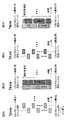
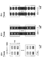
- FIGS. 2A and 2B are diagrams showing an example of RSSI measurement based on SS block.
- FIGS. 3A to 3D are diagrams showing an example of measurement resources of beam level RSSI when a plurality of CSI-RS resource configurations respectively corresponding to a plurality of beams are TDM.
- FIGS. 4A to 4D are diagrams showing an example of measurement resources of beam level RSSI in a case where a plurality of CSI-RS resource configurations respectively corresponding to a plurality of beams are subjected to FDM. It is a figure which shows an example of the assumption a about the relationship of RSRP measurement and UE receiving beam.
- FIG. 7 is a diagram showing an example of the relationship between the aspect 1-1 to the aspect 1-3.
- FIGS. 7A to 7E are diagrams showing an example of measurement resources of cell level RSSI when a plurality of CSI-RS resource configurations respectively corresponding to a plurality of beams are TDM.
- 8A to 8C are diagrams showing an example of cell-level RSSI measurement resources in the case where a plurality of CSI-RS resource configurations respectively corresponding to a plurality of beams are subjected to TDM and FDM.
- FIG. 21 is a diagram showing an example of the relationship between the aspect 2-1 to the aspect 2-4.
- 10A to 10C are diagrams showing an example of the relationship between the first embodiment and the second embodiment.
- the UE supports intra-frequency measurement which measures the serving carrier in connection and inter-frequency measurement which measures the non-serving carrier different from the serving carrier. .
- reference signal received power (RSRP) of the target carrier receives reference signal received power (RSRP) from the target carrier.
- RSSI received signal strength indicator
- RSSRQ reference signal received quality
- RSRP is defined as a linear average (power per resource element) over the power contribution [W] of a resource element carrying a CRS (Cell-specific Reference Signal) within a predetermined frequency bandwidth. If the upper layer indicates a measurement based on the discovery signal, the UE measures RSRP in subframes within the configured discovery signal opportunity.
- the reference point for RSRP is the antenna connector of the UE.
- RSRQ is defined as N ⁇ RSRP / RSSI.
- N is the number of RBs (resource blocks) of the RSSI measurement bandwidth.
- the numerator (RSRP) and denominator (RSSI) measurements are taken over the same set of resource blocks.
- the RSSI is observed by the UE only in certain OFDM symbols of measurement subframes within the measurement bandwidth over N RBs from all signal sources, including serving and non-serving cells between channels, adjacent channel interference, thermal noise, etc. Linear average of the transmitted and received power [W].
- the RSSI is measured only from OFDM, which includes the reference symbol for antenna port 0 of the measurement subframe, unless other resources are indicated by the upper layer. If the upper layer indicates all OFDM symbols for performing RSRQ measurement, then the RSSI is measured from all OFDM symbols in the DL part of the measurement subframe. If the upper layer indicates a subframe for performing RSRQ measurements, then the RSSI is measured from all OFDM symbols of the DL portion of the indicated subframe.
- the UE measures the RSSI in subframes within the configured discovery signal opportunity.
- the reference point for RSRQ is the antenna connector of the UE.
- RSRP CSI-RSRP: CSI-Reference Signal Received Power
- CSI-RSRP Channel State Information
- CSI-RSRP is defined as a linear average over the power contribution [W] of resource elements carrying CSI-RS configured for discovery signal measurement in a measurement frequency bandwidth in a subframe in a discovery signal opportunity.
- the reference point for CSI-RSRQ is the antenna connector of the UE.
- the UE in connected mode may measure RS-SINR (Reference Signal-Signal to Noise and Interference Ratio).
- RS-SINR is the linear average over the power contribution [W] of the resource element carrying CRS divided by the linear average of the noise and interference power contribution [W] across the resource element carrying CRS within the same frequency bandwidth Defined as The reference point for RS-SINR is the antenna connector of the UE. RS-SINR may be simply referred to as SINR.
- an RMTC (RSSI Measurement Timing Configuration) for License-Assisted Access (LAA) is defined.
- the UE configures RMTC according to the received parameters. Parameters include period, subframe offset, and measurement time. According to RMTC, resources can be set flexibly for RSSI measurement report as compared to RSSI setting for RSRQ.
- resource blocks including synchronization signals and broadcast channels are SS blocks (Synchronization Signal Block, synchronization Defining as a signal block, SS / PBCH (Physical Broadcast Channel) block) and performing initial connection based on the SS block is under consideration.
- SS blocks Synchronization Signal Block, synchronization Defining as a signal block, SS / PBCH (Physical Broadcast Channel) block
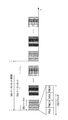
- FIG. 1 is a conceptual explanatory view of the SS block.
- the SS block can be used for the same application as the primary synchronization signal (PSS), secondary synchronization signal (SSS), and PBCH of the existing LTE system, PSS (NR-PSS) for NR, and SSS (NR- for NR). At least PBCH (NR-PBCH) for SSS) and NR.
- PSS primary synchronization signal
- SSS secondary synchronization signal
- PBCH NR- for NR
- NR-PBCH PBCH
- a synchronization signal (TSS: Tertiary SS) different from PSS and SSS may be included in the SS block.
- TSS Tertiary SS
- the NR-PBCH may include broadcast information and DMRS (Demodulation Reference Signal, DMRS for PBCH) for demodulation of the broadcast information.
- DMRS Demodulation Reference Signal
- the length of the SS block is, for example, a plurality of OFDM symbols.
- PSS of one symbol, SSS of one symbol, and PBCH of two symbols are time division multiplexed (TDM: Time Division Multiplexing).
- PSS and SSS, or PSS and PBCH may be time division multiplexed (TDM: Time Division Multiplexing) or may be frequency division multiplexed (FDM: Frequency Division Multiplexing).
- a set of one or more SS blocks may be referred to as SS bursts.
- the SS burst is composed of a plurality of SS blocks that are temporally continuous, but is not limited thereto.
- SS bursts may be composed of SS blocks in which frequency and / or time resources are continuous, and may be composed of non-consecutive SS blocks in which frequency and / or time resources are not.
- the SS burst is preferably transmitted every predetermined period (which may be called an SS burst period). Alternatively, the SS burst may not be transmitted every cycle (or may be transmitted aperiodically).
- the SS burst length and / or SS burst period may be transmitted in one or more subframes, one or more slots, and so on.
- the SS burst may include multiple SS blocks.
- one or more SS bursts may be referred to as an SS burst set (SS burst series).
- a base station Base Station
- TRP Transmission / Reception Point
- eNB eNodeB
- gNB gNodeB
- Multiple SS blocks may be transmitted by beam sweeping using one or more SS bursts.
- the SS burst set is transmitted periodically.
- the UE may control the reception process assuming that SS burst sets are transmitted periodically (at SS burst set period).
- the SS burst set period may be a default value (for example, 20 ms), or may be notified from a NW (network, for example, a base station) via higher layer signaling.
- a scenario in which a cell is configured by a plurality of beams is considered.
- the “beam” may be read as “resource”, “space resource”, “antenna port” or the like.
- Different SS blocks or CSI-RS resource configurations may be transmitted using different base station transmit beams (transmit beams).
- Different SS blocks may contain information indicating different SS block indices or beam indices.
- the UE reports measurement of the reception quality at beam level (per base station transmit beam) for selection of appropriate base station transmit beam (or combination of base station transmit beam and UE receive beam) It is conceivable to do. Also, in the multi-beam scenario, it is conceivable that the UE measures and reports the reception quality at the cell level (per cell) for appropriate cell selection.
- RSRP beam level RSRP, CSI-RS RSRP
- RSRP beam level RSRP
- CSI-RS RSRP RSRP for each beam
- cell level RSRP cell quality
- Is being considered.
- SS block RSRP is measured from SSS or DMRS for SSS and PBCH.
- CSI-RS RSRP is measured from CSI-RS in connected mode.
- Cell level RSRP may be derived from the top N beams.
- N may be set to one or more by higher layer signaling. If the number of beams is more than one, averaging may be used to derive cell level RSRP from multiple beams.
- CSI-RSs configured for Radio Resource Management (RRM) purposes may be used to derive cell level quality.
- RRM Radio Resource Management
- CSI-RS resource configuration for each transmission beam may be configured in the UE according to CSI-RS configuration information (CSI-RS resource configuration information) from the radio base station.
- CSI-RS resource configuration information may indicate time resources and / or frequency resources (CSI-RS RE (Resource Element)) for one or more CSI-RSs.
- the CSI-RS configuration information may be notified using higher layer signaling (for example, RRC (Radio Resource Control) signaling) or may be notified using broadcast information (for example, System Information Block (SIB)). It may be notified using a combination of higher layer signaling and broadcast information.
- RRC Radio Resource Control
- SIB System Information Block
- Beam level RSSI measurements based on SS block symbols and SS block bandwidth may not reflect actual interference.
- resources for RSSI measurement are set in the SS block, and as shown in FIG. 2B, SS blocks are also transmitted in cells B and C in measurement resources in SS block 1 of cell A.
- the measured interference received strength
- the measured interference hardly changes, regardless of the data traffic in other cells.
- the present inventors considered a method of deriving reception quality (for example, RSRQ or RS-SINR) based on CSI-RS, and reached the present invention.
- CSI-RS based reception quality is defined to reflect the effect of actual interference based on data traffic in other cells. Both beam level reception quality and cell level reception quality are considered.
- the reception strength may be RSSI
- the reception quality may be RSRQ
- the beam level receive strength may be beam level RSSI
- the beam level receive quality may be beam level RSRQ
- the cell level receive strength may be cell level RSSI
- the cell level receive quality is It may be a cell level RSRQ.
- the reception strength may be noise and interference for SINR
- the reception quality may be SINR
- the beam level received power may be beam level noise and interference
- the beam level received quality may be beam level SINR
- the cell level received power may be cell level noise and interference
- Cell level reception quality may be cell level SINR.
- RSSI may be read as noise and interference for SINR.
- RSRQ may be read as SINR.
- the result for each base station transmit beam may be read as the result for each CSI-RS resource configuration.
- the measurement of reception strength or reception quality may include derivation of reception strength or reception quality.
- the reception strength or reception quality may be directly measured.
- the UE measures beam level reception strength (beam level RSSI, or noise and interference at the beam level) based on CSI-RS.
- Beam level reception strength measurement may be performed based on CSI-RS configuration information.
- An OFDM symbol (time resource) for beam level reception strength measurement may include a corresponding CSI-RS RE (resource element) or may include a portion of the corresponding CSI-RS RE.
- the measurement bandwidth (frequency resource) of beam level reception strength may be notified for the corresponding CSI-RS resource.
- CSI-RS configuration information for RRM measurement information indicating time resource and / or frequency resource for measurement resource may be included in CSI-RS configuration information or notified by separate RRC signaling It may be done.
- FIG. 3 is a diagram illustrating an example of measurement resources of beam level RSSI when a plurality of CSI-RS resource configurations respectively corresponding to a plurality of beams are TDM. Several different beams are transmitted in CSI-RS in different symbols or slots.
- CSI-RS resource configuration 1 using beam 1 and CSI-RS resource configuration 2 using beam 2 are TDM.
- the CSI-RS frequency resources in each of CSI-RS resource configurations 1 and 2 are distributed (discrete).
- CSI-RS resource configurations 1 and 2 of FIG. 3A When CSI-RS resource configurations 1 and 2 of FIG. 3A are set, as shown in FIG. 3B, they correspond to CSI-RS resource configuration 1 (beam 1) and CSI-RS resource configuration 2 (beam 2), respectively.
- the measurement resource of the RSSI includes the corresponding CSI-RS RE in the corresponding symbol and may be a frequency resource of the entire measurement bandwidth.
- CSI-RS resource configurations 1 and 2 in FIG. 3A are set, as shown in FIG. 3C, measurement bandwidths in corresponding symbols as measurement resources for RSSI corresponding to CSI-RS resource configurations 1 and 2, respectively.
- Some frequency resources within may be configured.
- measurement resources of RSSI corresponding to CSI-RS resource configurations 1 and 2 respectively have corresponding symbols and measurement bandwidths.
- REs that do not include CSI-RS REs may be used.
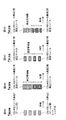
- FIG. 4 is a diagram illustrating an example of measurement resources of beam level RSSI when a plurality of CSI-RS resource configurations respectively corresponding to a plurality of beams are subjected to FDM. Multiple different transmit beams are transmitted in CSI-RS in different PRBs.
- CSI-RS resource configuration 1 using beam 1 and CSI-RS resource configuration 2 using beam 2 are FDM.
- the CSI-RS frequency resources in each of CSI-RS resource configurations 1 and 2 are distributed (discrete).
- measurement resources of RSSI corresponding to CSI-RS resource configurations 1 and 2 respectively correspond to corresponding CSI-RS REs. It may be a continuous frequency resource within the corresponding and corresponding measurement bandwidth.
- CSI-RS resource configurations 1 and 2 of FIG. 4A are set, as shown in FIG. 4C, a part of the measurement bandwidth is used as a measurement resource of RSSI corresponding to each of CSI-RS resource configurations 1 and 2.
- Frequency resources eg, CSI-RS RE
- CSI-RS RE may be configured.
- measurement resources of RSSI corresponding to CSI-RS resource configurations 1 and 2 respectively correspond to corresponding symbols and corresponding measurements.
- REs that do not include CSI-RS REs may be used.
- the UE can measure the beam level RSSI based on CSI-RS or the noise and interference of the beam level. Also, by using CSI-RS, it is possible to measure the beam level reception strength that reflects the effect of actual interference based on data traffic in other cells.
- the UE may derive beam level reception quality based on the beam level RSRQ and the beam level reception strength.
- the beam level RSRQ may be derived from the measured beam level RSRP and the measured beam level RSSI using this equation.
- the beam level SINR may be derived from the measured beam level RSRP and the noise and interference of the measured beam level using this equation.
- the UE can derive an accurate beam level RSRQ or beam level SINR based on the CSI-RS.
- the UE may derive cell level reception quality based on beam level reception quality.
- Cell level reception quality is derived as a combination of at least one beam level reception quality.
- beam level reception quality is referred to as beam level result
- cell level reception quality is referred to as cell level result.
- the beam level results selected for coupling may be, for example, all beam level results or the top N beam level results, or beam level results exceeding the threshold of absolute value It may be the highest beam level result, or it may be the highest beam level result of the beam level results within the threshold relative to the highest beam level result, or it may exceed the absolute value threshold
- the beam level results may be the upper at most N beam level results or the beam level results within the threshold range relative to the highest beam level result at most N beam levels It may be a result.
- the method of combining the selected beam level results may be an average of the selected beam level results or a weighted average of the selected beam level results.
- the UE can derive the cell level RSRQ from the beam level RSRQ. Also, the UE can derive cell level SINR from beam level SINR.
- the UE may measure the beam level received power using the UE receive beam (receive beam).
- the beam level RSRP may be the highest RSRP available from the beam pair link.
- the beam pair link is, for example, a combination of a base station transmit beam and a UE receive beam.
- the UE performs RSRP measurement using multiple UE receive beams in the same CSI-RS resource configuration (same transmit beam), and determines the highest RSRP for that CSI-RS resource configuration.
- UE measures RSRP using reception beams 1 to 4 in CSI-RS resource configuration 1 among CSI-RS resource configurations 1 to 4, and RSRP corresponding to reception beam 3 is the highest. Therefore, this RSRP is regarded as beam level RSRP for CSI-RS resource configuration 1.
- the UE determines a UE receive beam for RSRP measurement based on the UE's implementation. For example, the UE may randomly determine the receive beam, or may consider the average of RSRP measured using several receive beams as beam level RSRP.
- the UE receive beam for RSRP measurement is not limited to the UE receive beam corresponding to the highest RSRP.
- the UE may determine the UE receive beam for beam level receive power measurement using the following options a or b.
- Option a is beam level reception intensity measurement when performing beam level RSRP measurement of assumption a.
- the UE measures the beam level reception strength for the CSI-RS resource configuration using the receive beam used for the highest RSRP measurement for a certain CSI-RS resource configuration.
- Option b is beam level reception intensity measurement when performing beam level RSRP measurement of assumption b.
- the UE determines the receive beam to use for beam-level receive strength measurement as in scenario b. For example, the UE may randomly determine the receive beam, or may consider the average of the receive strengths measured using several receive beams as the beam level receive strength.
- the receive beam used for beam level receive strength may be the same as the receive beam used for beam level RSRP.
- the receive beam used for beam level RSRP measurement and the receive beam used for beam level receive intensity measurement are aligned and measured Accuracy can be increased. If the RSRP of one receive beam is the highest for one CSI-RS resource configuration and the RSRP of another receive beam is the highest for another CSI-RS resource configuration, interference will be different due to different receive beams. . Also, the interference measured at the resource corresponding to one transmit beam and the interference measured at the resource corresponding to another transmit beam are different.
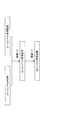
- FIG. 6 is a view showing an example of the relationship between the aspect 1-1 to the aspect 1-3.
- the UE measures beam level reception strength based on each CSI-RS resource configuration.
- the UE derives the beam level reception quality based on the beam level RSRP and the beam level reception strength.
- the UE derives cell level reception quality based on the one or more beam level reception qualities.
- the UE derives or measures cell level RSRP or cell level reception strength (cell level RSSI, or cell level noise and interference).
- the UE may derive cell level reception strength based on the beam level reception strength.
- the UE may derive a combination of several beam level reception strengths obtained from aspect 1-1 or aspect 1-2 as cell level reception strength.
- the beam level reception strength is called a beam level result
- the cell level reception strength is called a cell level result.
- the beam level results selected for coupling may be, for example, all beam level results or the top N beam level results, or beam level results exceeding the threshold of absolute value It may be the highest beam level result, or it may be the highest beam level result of the beam level results within the threshold relative to the highest beam level result, or it may exceed the absolute value threshold
- the beam level results may be the upper at most N beam level results or the beam level results within the threshold range relative to the highest beam level result at most N beam levels It may be a result.
- the method of combining the selected beam level results may be an average of the selected beam level results or a weighted average of the selected beam level results.
- the UE can derive the cell level RSSI from the beam level RSSI. Also, the UE can derive cell level noise and interference from beam level noise and interference.
- the UE may measure cell level received power.
- the UE may perform cell level reception strength measurement based on CSI-RS based on CSI-RS configuration information for RRM measurement.
- the UE may further perform cell level reception strength measurement based on CSI-RS based on the additional information.
- the additional information may be notified by RRC signaling.
- the UE may perform measurement in the indicated measurement bandwidth of the OFDM symbol including all the indicated CSI-RS resources, or a part of the measurement bandwidth of the OFDM symbol (for example, , CSI-RS RE)).
- the UE may perform measurement in the OFDM symbol including the CSI-RS resource indicated by the additional information, or part of the measurement bandwidth of the OFDM symbol (for example, only CSI-RS RE).
- the measurement may be performed in
- the additional information may indicate a default CSI-RS resource or may indicate a grouping of CSI-RS resources.
- FIG. 7 is a diagram illustrating an example of cell-level RSSI measurement resources when a plurality of CSI-RS resource configurations respectively corresponding to a plurality of beams are TDM. Several different beams are transmitted in CSI-RS in different symbols or slots.
- CSI-RS resource configuration 1 using beam 1 and CSI-RS resource configuration 2 using beam 2 are TDM.
- the CSI-RS frequency resources in each of CSI-RS resource configurations 1 and 2 are distributed (discrete).
- the measurement resource of cell level RSSI is the CSI-RS resource. It may be the frequency resource of the entire measurement bandwidth in the symbol of configuration 1. Also, the measurement resource of cell level RSSI may be all CSI-RS REs in the default CSI-RS resource configuration. Also, if no default CSI-RS resource configuration is indicated, the cell-level RSSI measurement resource may be the frequency resource of the entire measurement bandwidth in all CSI-RS resource configuration symbols, or all CSI-RS resource configurations. It may be RS RE.
- the cell level The measurement resource of RSSI may be a frequency resource of the entire measurement bandwidth in the symbols of CSI-RS resource configurations 1 and 2. Also, the measurement resource of cell level RSSI may be all CSI-RS REs.
- the measurement resource of cell level RSSI is the CSI-RS resource.
- the measurement resources of cell level RSSI are REs that do not include CSI-RS RE among all measurement bandwidths in all CSI-RS resource configuration symbols. It is also good.
- the cell level The measurement resource of the RSSI may be an RE that does not include the CSI-RS RE in the entire measurement bandwidth in the symbols of the CSI-RS resource configurations 1 and 2.
- FIG. 8 is a diagram showing an example of measurement resources of cell level RSSI in a case where a plurality of CSI-RS resource configurations respectively corresponding to a plurality of beams are subjected to TDM and FDM.
- multiple different beams are transmitted in CSI-RS in different time / frequency resources in one RB.
- the measurement resource of cell level RSSI may be the entire measurement bandwidth including all CSI-RS resources. Also, the measurement resource of cell level RSSI may be all CSI-RS REs.
- cell-level RSSI measurement resources are CSI-RS RE among the entire measurement bandwidth including all CSI-RS resources. It may be RE that does not contain
- the UE can measure cell level RSSI or cell level noise and interference.
- the UE may derive beam level reception quality without beam level RSRP or without beam level reception strength.
- the UE may derive the beam level reception quality using the following aspect 2-3-a or aspect 2-3-b.
- the UE derives the beam level reception quality based on the measured beam level RSRP and the measured or derived cell level reception strength. That is, the UE uses cell level results only for the received strength.
- the embodiment 2-3-a since a common cell level reception strength is used for all CSI-RS resource configurations (beams) of the serving cell, the relationship between beam level RSRP and beam level reception quality is the same in all CSI-RS resource configurations. , The significance of the embodiment 2-3-a becomes smaller. On the other hand, since measurement of different frequencies in other carriers or measurement of neighboring cells is simple, the embodiment 2-3-a can be used.
- the UE derives the beam level reception quality based on the derived cell level RSRP and the measured beam level reception strength. That is, the UE uses cell-level results for RSRP only.
- the UE can derive the beam level RSRQ or the beam level SINR even if one of RSRP and the reception strength is a cell level result.
- the UE may derive the cell level reception quality based on the result of at least one of aspects 2-1 to 2-3.
- the UE may derive the cell level reception quality using the following aspect 2-4-a or aspect 2-4-b.
- the UE derives cell level reception quality based on the derived cell level RSRP and the measured or derived cell level reception strength.
- An inaccurate cell level reception quality may be derived by being based on two derived values.
- the UE derives cell level reception quality based on the combination of beam level reception qualities derived according to aspect 2-3.
- beam level reception quality is referred to as beam level result
- cell level reception quality is referred to as cell level result.
- the beam level results selected for coupling may be, for example, all beam level results or the top N beam level results, or beam level results exceeding the threshold of absolute value It may be the highest beam level result, or it may be the highest beam level result of the beam level results within the threshold relative to the highest beam level result, or it may exceed the absolute value threshold
- the beam level results may be the upper at most N beam level results or the beam level results within the threshold range relative to the highest beam level result at most N beam levels It may be a result.
- the method of combining the selected beam level results may be an average of the selected beam level results or a weighted average of the selected beam level results.
- the UE can derive the cell level RSRQ or the cell level SINR based on the result of at least one of the aspects 2-1 to 2-3.
- FIG. 9 is a view showing an example of the relationship between the aspect 2-1 to the aspect 2-4.
- the UE can measure or derive the cell level reception strength.
- the UE can derive cell level reception strength from the beam level reception strength.
- the UE can measure the cell level reception strength.
- the UE can derive beam level reception quality based on the beam level RSRP and the cell level reception strength.
- the UE can derive beam level reception quality based on the cell level RSRP and the beam level reception strength.
- the UE can derive cell level reception quality based on cell level RSRP and cell level reception strength.
- the UE derives cell level reception quality based on the combination of beam level reception qualities derived according to aspect 2-3.
- the UE may measure the beam level RSRP directly based on each CSI-RS resource configuration.
- the UE may derive cell level RSRP based on one or more beam levels RSRP.
- the UE may directly measure the beam level reception strength based on each CSI-RS resource configuration.
- the UE may directly measure the cell level reception strength.
- the UE may derive cell level reception strength based on one or more beam level reception qualities.
- the UE derives the beam level reception quality based on the measured beam level RSRP and the beam level reception strength measured according to aspect 1-1. It is also good. This case provides the most accurate beam level reception quality.
- the UE may derive beam level reception quality based on the measured beam level RSRP and the cell level reception strength measured according to aspect 2-2. This case is used to measure different frequencies on other carriers or to measure neighboring cells.
- the UE may derive the beam level reception quality based on the measured beam level RSRP and the cell level reception strength measured according to aspect 2-1. This case is of little significance.
- the UE may derive the beam level reception quality based on the derived cell level RSRP and the beam level reception strength measured according to aspect 1-1. This case is of little significance.
- the UE may derive cell level reception quality based on the derived cell level RSRP and the measured or derived cell level reception strength. Also, the UE may derive cell level reception quality based on the derived beam level reception quality.
- the NR may support different types of reception strength and / or measurement (or derivation) methods of reception quality as described above.
- the measurement method may be configurable, or according to UE RRC state (idle mode and connected mode), different purpose (eg same frequency measurement and different frequency measurement) and / or UE capability according to UE capability. It may be applied.
- NR sets aspect 1-1 to beam level reception strength measurement in serving cell measurement, and sets aspect 2-2 to cell level reception strength measurement in neighboring cell measurement and / or different frequency measurement. It is also good.
- NR sets aspect 1-1 for beam level receive strength measurement for same frequency measurement of serving cell and neighboring cells on serving carrier, and cell level receive for different frequency measurement on other carriers
- Aspect 2-2 may be set for intensity measurement.
- the radio base station when the radio base station transmits a plurality of CSI-RS resources in one RB using a digital or hybrid beamforming scheme, the radio base station performs the process of aspect 2-2 with respect to cell level reception strength measurement.
- Option a may be used.
- wireless communication system Wireless communication system
- communication is performed using any one or a combination of the wireless communication methods according to the above embodiments of the present invention.
- FIG. 11 is a diagram showing an example of a schematic configuration of a wireless communication system according to an embodiment of the present invention.
- the radio communication system 1 applies carrier aggregation (CA) and / or dual connectivity (DC) in which a plurality of basic frequency blocks (component carriers) each having a system bandwidth (for example, 20 MHz) of the LTE system as one unit are integrated. can do.
- CA carrier aggregation
- DC dual connectivity
- the wireless communication system 1 includes LTE (Long Term Evolution), LTE-A (LTE-Advanced), LTE-B (LTE-Beyond), SUPER 3G, IMT-Advanced, 4G (4th generation mobile communication system), and 5G. It may be called (5th generation mobile communication system), NR (New Radio), FRA (Future Radio Access), New-RAT (Radio Access Technology) or the like, or may be called a system for realizing these.
- the radio communication system 1 includes a radio base station 11 forming a macrocell C1 with a relatively wide coverage, and radio base stations 12 (12a to 12c) disposed in the macrocell C1 and forming a small cell C2 narrower than the macrocell C1. And. Moreover, the user terminal 20 is arrange
- the user terminal 20 can be connected to both the radio base station 11 and the radio base station 12. It is assumed that the user terminal 20 simultaneously uses the macro cell C1 and the small cell C2 by CA or DC. Also, the user terminal 20 may apply CA or DC using a plurality of cells (CCs) (for example, 5 or less CCs, 6 or more CCs).
- CCs cells
- Communication can be performed between the user terminal 20 and the radio base station 11 using a relatively low frequency band (for example, 2 GHz) and a narrow bandwidth carrier (also called an existing carrier, legacy carrier, etc.).
- a carrier having a wide bandwidth in a relatively high frequency band for example, 3.5 GHz, 5 GHz, etc.
- the configuration of the frequency band used by each wireless base station is not limited to this.
- a wired connection for example, an optical fiber conforming to a Common Public Radio Interface (CPRI), an X2 interface, etc.
- a wireless connection Can be configured.
- the radio base station 11 and each radio base station 12 are connected to the higher station apparatus 30 and connected to the core network 40 via the higher station apparatus 30.
- the upper station apparatus 30 includes, for example, an access gateway apparatus, a radio network controller (RNC), a mobility management entity (MME), and the like, but is not limited thereto. Further, each wireless base station 12 may be connected to the higher station apparatus 30 via the wireless base station 11.
- RNC radio network controller
- MME mobility management entity
- Each user terminal 20 is a terminal compatible with various communication schemes such as LTE and LTE-A, and may include not only mobile communication terminals (mobile stations) but also fixed communication terminals (fixed stations).
- orthogonal frequency division multiple access (OFDMA) is applied to the downlink as a radio access scheme, and single carrier frequency division multiple access (SC-FDMA: single carrier) to the uplink.
- SC-FDMA single carrier frequency division multiple access
- Frequency Division Multiple Access and / or OFDMA is applied.
- OFDMA is a multicarrier transmission scheme in which a frequency band is divided into a plurality of narrow frequency bands (subcarriers) and data is mapped to each subcarrier to perform communication.
- SC-FDMA is a single carrier transmission method that reduces interference between terminals by dividing the system bandwidth into bands of one or continuous resource blocks for each terminal and using different bands by a plurality of terminals.
- the uplink and downlink radio access schemes are not limited to these combinations, and other radio access schemes may be used.
- a downlink shared channel (PDSCH: Physical Downlink Shared Channel) shared by each user terminal 20, a broadcast channel (PBCH: Physical Broadcast Channel), a downlink L1 / L2 control channel, etc. are used as downlink channels. Used. User data, upper layer control information, SIB (System Information Block) and the like are transmitted by the PDSCH. Also, a MIB (Master Information Block) is transmitted by the PBCH.
- PDSCH Physical Downlink Shared Channel
- PBCH Physical Broadcast Channel
- SIB System Information Block
- MIB Master Information Block
- the downlink L1 / L2 control channel includes PDCCH (Physical Downlink Control Channel), EPDCCH (Enhanced Physical Downlink Control Channel), PCFICH (Physical Control Format Indicator Channel), PHICH (Physical Hybrid-ARQ Indicator Channel) and the like.
- Downlink control information (DCI) including scheduling information of PDSCH and / or PUSCH is transmitted by PDCCH.
- scheduling information may be notified by DCI.
- DCI scheduling DL data reception may be referred to as DL assignment
- DCI scheduling UL data transmission may be referred to as UL grant.
- an uplink shared channel (PUSCH: Physical Uplink Shared Channel) shared by each user terminal 20, an uplink control channel (PUCCH: Physical Uplink Control Channel), a random access channel (PRACH: Physical Random Access Channel) or the like is used.
- User data, upper layer control information, etc. are transmitted by PUSCH.
- downlink radio quality information (CQI: Channel Quality Indicator), delivery confirmation information, scheduling request (SR: Scheduling Request), etc. are transmitted by the PUCCH.
- the PRACH transmits a random access preamble for establishing a connection with a cell.
- a cell-specific reference signal (CRS: Cell-specific Reference Signal), a channel state information reference signal (CSI-RS: Channel State Information-Reference Signal), a demodulation reference signal (DMRS: DeModulation Reference Signal, positioning reference signal (PRS), etc.
- CRS Cell-specific Reference Signal
- CSI-RS Channel State Information-Reference Signal
- DMRS DeModulation Reference Signal
- PRS positioning reference signal
- SRS Sounding Reference Signal
- DMRS demodulation reference signal
- PRS positioning reference signal
- DMRS Demodulation reference signal
- PRS positioning reference signal
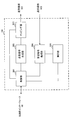
- FIG. 12 is a diagram showing an example of the entire configuration of a radio base station according to an embodiment of the present invention.
- the radio base station 10 includes a plurality of transmitting and receiving antennas 101, an amplifier unit 102, a transmitting and receiving unit 103, a baseband signal processing unit 104, a call processing unit 105, and a transmission path interface 106.
- each of the transmitting and receiving antenna 101, the amplifier unit 102, and the transmitting and receiving unit 103 may be configured to include one or more.
- User data transmitted from the radio base station 10 to the user terminal 20 by downlink is input from the higher station apparatus 30 to the baseband signal processing unit 104 via the transmission path interface 106.
- the baseband signal processing unit 104 performs packet data convergence protocol (PDCP) layer processing, user data division / combination, RLC layer transmission processing such as RLC (Radio Link Control) retransmission control, and MAC (Medium Access) for user data.
- Control Transmission processing such as retransmission control (for example, HARQ transmission processing), scheduling, transmission format selection, channel coding, inverse fast Fourier transform (IFFT) processing, precoding processing, etc. It is transferred to 103. Further, transmission processing such as channel coding and inverse fast Fourier transform is also performed on the downlink control signal and transferred to the transmission / reception unit 103.
- the transmission / reception unit 103 converts the baseband signal output from the baseband signal processing unit 104 for each antenna into a radio frequency band and transmits the baseband signal.
- the radio frequency signal frequency-converted by the transmitting and receiving unit 103 is amplified by the amplifier unit 102 and transmitted from the transmitting and receiving antenna 101.
- the transmission / reception unit 103 can be configured of a transmitter / receiver, a transmission / reception circuit, or a transmission / reception device described based on the common recognition in the technical field according to the present invention.
- the transmitting and receiving unit 103 may be configured as an integrated transmitting and receiving unit, or may be configured from a transmitting unit and a receiving unit.
- the radio frequency signal received by the transmission / reception antenna 101 is amplified by the amplifier unit 102.
- the transmitting and receiving unit 103 receives the upstream signal amplified by the amplifier unit 102.
- the transmission / reception unit 103 frequency-converts the received signal into a baseband signal and outputs the result to the baseband signal processing unit 104.
- the transmission path interface 106 transmits and receives signals to and from the higher station apparatus 30 via a predetermined interface. Also, the transmission path interface 106 transmits / receives signals (backhaul signaling) to / from the other wireless base station 10 via an inter-base station interface (for example, an optical fiber conforming to CPRI (Common Public Radio Interface), X2 interface). May be
- an inter-base station interface for example, an optical fiber conforming to CPRI (Common Public Radio Interface), X2 interface.
- the transmission / reception unit 103 may transmit a reference signal (eg, CSI-RS) in one or more reference signal resources (eg, CSI-RS resource configuration) for channel state measurement.
- a reference signal eg, CSI-RS
- reference signal resources eg, CSI-RS resource configuration
- FIG. 13 is a diagram showing an example of a functional configuration of a wireless base station according to an embodiment of the present invention.
- the functional block of the characteristic part in this embodiment is mainly shown, and suppose that the wireless base station 10 also has another functional block required for wireless communication.
- the baseband signal processing unit 104 at least includes a control unit (scheduler) 301, a transmission signal generation unit 302, a mapping unit 303, a reception signal processing unit 304, and a measurement unit 305. Note that these configurations may be included in the wireless base station 10, and some or all of the configurations may not be included in the baseband signal processing unit 104.
- a control unit (scheduler) 301 performs control of the entire radio base station 10.
- the control unit 301 can be configured of a controller, a control circuit, or a control device described based on the common recognition in the technical field according to the present invention.
- the control unit 301 controls, for example, generation of a signal by the transmission signal generation unit 302, assignment of a signal by the mapping unit 303, and the like. Further, the control unit 301 controls reception processing of a signal by the reception signal processing unit 304, measurement of a signal by the measurement unit 305, and the like.
- the control unit 301 schedules (for example, resources) system information, downlink data signals (for example, signals transmitted on PDSCH), downlink control signals (for example, signals transmitted on PDCCH and / or EPDCCH, delivery confirmation information, etc.) Control allocation). Further, the control unit 301 controls generation of the downlink control signal, the downlink data signal, and the like based on the result of determining whether the retransmission control for the uplink data signal is necessary or not. The control unit 301 also controls scheduling of synchronization signals (for example, PSS (Primary Synchronization Signal) / SSS (Secondary Synchronization Signal), downlink reference signals (for example, CRS, CSI-RS, DMRS) and the like.
- PSS Primary Synchronization Signal
- SSS Synchronization Signal
- the control unit 301 may use an uplink data signal (for example, a signal transmitted on PUSCH), an uplink control signal (for example, a signal transmitted on PUCCH and / or PUSCH, delivery confirmation information, etc.), a random access preamble (for example, PRACH). Control the scheduling of transmitted signals, uplink reference signals, etc.
- an uplink data signal for example, a signal transmitted on PUSCH
- an uplink control signal for example, a signal transmitted on PUCCH and / or PUSCH, delivery confirmation information, etc.
- a random access preamble for example, PRACH
- the transmission signal generation unit 302 generates a downlink signal (downlink control signal, downlink data signal, downlink reference signal or the like) based on an instruction from the control unit 301, and outputs the downlink signal to the mapping unit 303.
- the transmission signal generation unit 302 can be configured from a signal generator, a signal generation circuit or a signal generation device described based on the common recognition in the technical field according to the present invention.
- the transmission signal generation unit 302 generates, for example, DL assignment for notifying downlink data allocation information and / or UL grant for notifying uplink data allocation information, based on an instruction from the control unit 301.
- DL assignment and UL grant are both DCI and follow DCI format.
- coding processing and modulation processing are performed on the downlink data signal according to a coding rate, a modulation method, and the like determined based on channel state information (CSI: Channel State Information) and the like from each user terminal 20.
- CSI Channel State Information
- Mapping section 303 maps the downlink signal generated by transmission signal generation section 302 to a predetermined radio resource based on an instruction from control section 301, and outputs the mapped downlink signal to transmission / reception section 103.
- the mapping unit 303 may be configured of a mapper, a mapping circuit or a mapping device described based on the common recognition in the technical field according to the present invention.
- the reception signal processing unit 304 performs reception processing (for example, demapping, demodulation, decoding, and the like) on the reception signal input from the transmission / reception unit 103.
- the reception signal is, for example, an uplink signal (uplink control signal, uplink data signal, uplink reference signal, etc.) transmitted from the user terminal 20.
- the received signal processing unit 304 can be configured from a signal processor, a signal processing circuit or a signal processing device described based on the common recognition in the technical field according to the present invention.
- the reception signal processing unit 304 outputs the information decoded by the reception process to the control unit 301. For example, when the PUCCH including the HARQ-ACK is received, the HARQ-ACK is output to the control unit 301. Further, the reception signal processing unit 304 outputs the reception signal and / or the signal after reception processing to the measurement unit 305.
- the measurement unit 305 performs measurement on the received signal.
- the measuring unit 305 can be configured from a measuring device, a measuring circuit or a measuring device described based on the common recognition in the technical field according to the present invention.
- the measurement unit 305 may perform Radio Resource Management (RRM) measurement, Channel State Information (CSI) measurement, and the like based on the received signal.
- the measurement unit 305 may use received power (for example, RSRP (Reference Signal Received Power)), received quality (for example, RSRQ (Reference Signal Received Quality), SINR (Signal to Interference plus Noise Ratio)), signal strength (for example, RSSI (for example). Received Signal Strength Indicator), propagation path information (eg, CSI), etc. may be measured.
- the measurement result may be output to the control unit 301.
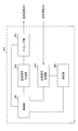
- FIG. 14 is a diagram showing an example of the entire configuration of a user terminal according to an embodiment of the present invention.
- the user terminal 20 includes a plurality of transmitting and receiving antennas 201, an amplifier unit 202, a transmitting and receiving unit 203, a baseband signal processing unit 204, and an application unit 205.
- each of the transmitting and receiving antenna 201, the amplifier unit 202, and the transmitting and receiving unit 203 may be configured to include one or more.
- the radio frequency signal received by the transmission / reception antenna 201 is amplified by the amplifier unit 202.
- the transmitting and receiving unit 203 receives the downlink signal amplified by the amplifier unit 202.
- the transmission / reception unit 203 frequency-converts the received signal into a baseband signal and outputs the result to the baseband signal processing unit 204.
- the transmission / reception unit 203 can be configured of a transmitter / receiver, a transmission / reception circuit or a transmission / reception device described based on the common recognition in the technical field according to the present invention.
- the transmission / reception unit 203 may be configured as an integrated transmission / reception unit, or may be configured from a transmission unit and a reception unit.
- the baseband signal processing unit 204 performs reception processing of FFT processing, error correction decoding, retransmission control, and the like on the input baseband signal.
- the downlink user data is transferred to the application unit 205.
- the application unit 205 performs processing on a layer higher than the physical layer and the MAC layer. Moreover, broadcast information may also be transferred to the application unit 205 among downlink data.
- uplink user data is input from the application unit 205 to the baseband signal processing unit 204.
- the baseband signal processing unit 204 performs transmission processing of retransmission control (for example, transmission processing of HARQ), channel coding, precoding, discrete Fourier transform (DFT) processing, IFFT processing, etc. It is transferred to 203.
- the transmission / reception unit 203 converts the baseband signal output from the baseband signal processing unit 204 into a radio frequency band and transmits it.
- the radio frequency signal frequency-converted by the transmitting and receiving unit 203 is amplified by the amplifier unit 202 and transmitted from the transmitting and receiving antenna 201.
- the transmission / reception unit 203 may receive a reference signal (for example, CSI-RS) in one or more reference signal resources (for example, CSI-RS resource configuration) for channel state measurement.
- a reference signal for example, CSI-RS
- reference signal resources for example, CSI-RS resource configuration
- the transmitting / receiving unit 203 may perform the first reception power (eg, beam level RSRP and / or cell level RSRP), the second reception power (eg, beam level reception strength and / or cell level reception strength), and the reception quality (eg, , And / or beam level reception quality and / or cell level reception quality) may be transmitted to the radio base station.
- the first reception power eg, beam level RSRP and / or cell level RSRP
- the second reception power eg, beam level reception strength and / or cell level reception strength
- the reception quality eg, , And / or beam level reception quality and / or cell level reception quality
- FIG. 15 is a diagram showing an example of a functional configuration of a user terminal according to an embodiment of the present invention.
- the functional block of the characteristic part in this embodiment is mainly shown, and it is assumed that the user terminal 20 also has another functional block required for wireless communication.
- the baseband signal processing unit 204 included in the user terminal 20 at least includes a control unit 401, a transmission signal generation unit 402, a mapping unit 403, a reception signal processing unit 404, and a measurement unit 405. Note that these configurations may be included in the user terminal 20, and some or all of the configurations may not be included in the baseband signal processing unit 204.
- the control unit 401 controls the entire user terminal 20.
- the control unit 401 can be configured of a controller, a control circuit, or a control device described based on the common recognition in the technical field according to the present invention.
- the control unit 401 controls, for example, signal generation by the transmission signal generation unit 402, assignment of signals by the mapping unit 403, and the like. Further, the control unit 401 controls reception processing of a signal by the reception signal processing unit 404, measurement of a signal by the measurement unit 405, and the like.
- the control unit 401 acquires the downlink control signal and the downlink data signal transmitted from the radio base station 10 from the reception signal processing unit 404.
- the control unit 401 controls the generation of the uplink control signal and / or the uplink data signal based on the result of determining the necessity of the retransmission control for the downlink control signal and / or the downlink data signal.
- control unit 401 When the control unit 401 acquires various types of information notified from the radio base station 10 from the received signal processing unit 404, the control unit 401 may update parameters used for control based on the information.
- the transmission signal generation unit 402 generates an uplink signal (uplink control signal, uplink data signal, uplink reference signal or the like) based on an instruction from the control unit 401, and outputs the uplink signal to the mapping unit 403.
- the transmission signal generation unit 402 can be configured from a signal generator, a signal generation circuit, or a signal generation device described based on the common recognition in the technical field according to the present invention.
- the transmission signal generation unit 402 generates, for example, an uplink control signal related to delivery confirmation information, channel state information (CSI), and the like based on an instruction from the control unit 401. Further, the transmission signal generation unit 402 generates an uplink data signal based on an instruction from the control unit 401. For example, when the downlink control signal notified from the radio base station 10 includes a UL grant, the transmission signal generation unit 402 is instructed by the control unit 401 to generate an uplink data signal.
- CSI channel state information
- Mapping section 403 maps the uplink signal generated by transmission signal generation section 402 to a radio resource based on an instruction from control section 401, and outputs the uplink signal to transmission / reception section 203.
- the mapping unit 403 may be configured of a mapper, a mapping circuit or a mapping device described based on the common recognition in the technical field according to the present invention.
- the reception signal processing unit 404 performs reception processing (for example, demapping, demodulation, decoding, and the like) on the reception signal input from the transmission / reception unit 203.
- the reception signal is, for example, a downlink signal (a downlink control signal, a downlink data signal, a downlink reference signal, or the like) transmitted from the radio base station 10.
- the received signal processing unit 404 can be composed of a signal processor, a signal processing circuit or a signal processing device described based on the common recognition in the technical field according to the present invention. Also, the received signal processing unit 404 can constitute a receiving unit according to the present invention.
- the reception signal processing unit 404 outputs the information decoded by the reception process to the control unit 401.
- the received signal processing unit 404 outputs, for example, broadcast information, system information, RRC signaling, DCI, and the like to the control unit 401. Further, the reception signal processing unit 404 outputs the reception signal and / or the signal after reception processing to the measurement unit 405.
- the measurement unit 405 performs measurement on the received signal.
- the measuring unit 405 can be configured of a measuring device, a measuring circuit or a measuring device described based on the common recognition in the technical field according to the present invention.
- the measurement unit 405 may perform RRM measurement, CSI measurement, and the like based on the received signal.
- the measurement unit 405 may measure reception power (for example, RSRP), reception quality (for example, RSRQ, SINR), signal strength (for example, RSSI), channel information (for example, CSI), and the like.
- the measurement result may be output to the control unit 401.
- the measurement unit 405 may be configured to calculate a first received power of a reference signal (eg, beam level RSRP or cell level RSRP) and a second received power (eg, beam level) at a radio resource associated with one or more reference signal resources. Received strength or cell level received strength) may be measured. Also, the measurement unit 405 may derive the reception quality (for example, beam level reception quality or cell level reception quality) of the cell based on the first reception power and the second reception power.
- a reference signal eg, beam level RSRP or cell level RSRP
- a second received power eg, beam level
- the measuring unit 405 measures the first received power in each reference signal resource, measures the second received power in the radio resource associated with each reference signal resource, and measures the first received power corresponding to each reference signal resource.
- the second reception power corresponding to each reference signal resource may derive the reception quality corresponding to each reference signal resource.
- the measurement unit 405 may derive the reception quality of the cell based on the reception quality of each reference signal resource.
- the measurement unit 405 may be a radio resource that is a corresponding reference signal resource or a resource that includes a corresponding reference signal resource and that has a bandwidth notified from a radio base station.
- the radio resource is a reference signal resource notified from the radio base station or a resource including the reference signal resource notified from the radio base station and having a bandwidth notified from the radio base station, and the measurement unit 405 May measure the second received power of the cell at the radio resource.
- the measurement unit 405 may derive the second reception power (for example, cell level reception strength) of the cell based on the second reception power (for example, beam level reception strength) corresponding to each reference signal resource. .
- the measurement unit 405 receives a cell based on the first received power (eg, beam level RSRP) corresponding to each reference signal resource and the second received power of the cell (eg, cell level received strength).
- the quality eg, cell level reception quality
- the measurement unit 405 receives the cell based on the first received power of the cell (eg, cell level RSRP) and the second received power (eg, beam level received strength) corresponding to each reference signal resource.
- the quality (eg, cell level reception quality) may be derived.
- each functional block (components) are realized by any combination of hardware and / or software.
- the implementation method of each functional block is not particularly limited. That is, each functional block may be realized using one physically and / or logically coupled device, or directly and / or two or more physically and / or logically separated devices. Or it may connect indirectly (for example, using a wire communication and / or radio), and it may be realized using a plurality of these devices.
- a wireless base station, a user terminal, and the like in an embodiment of the present invention may function as a computer that performs the processing of the wireless communication method of the present invention.
- FIG. 16 is a diagram showing an example of a hardware configuration of a radio base station and a user terminal according to an embodiment of the present invention.
- the above-described wireless base station 10 and user terminal 20 may be physically configured as a computer device including a processor 1001, a memory 1002, a storage 1003, a communication device 1004, an input device 1005, an output device 1006, a bus 1007 and the like. Good.
- the term “device” can be read as a circuit, a device, a unit, or the like.
- the hardware configuration of the radio base station 10 and the user terminal 20 may be configured to include one or more of the devices illustrated in the figure, or may be configured without including some devices.
- processor 1001 may be implemented by one or more chips.
- Each function in the radio base station 10 and the user terminal 20 is calculated by causing the processor 1001 to read predetermined software (program) on hardware such as the processor 1001 and the memory 1002, and the communication device 1004 is performed. This is realized by controlling communication, and controlling reading and / or writing of data in the memory 1002 and the storage 1003.
- the processor 1001 operates, for example, an operating system to control the entire computer.
- the processor 1001 may be configured by a central processing unit (CPU) including an interface with a peripheral device, a control device, an arithmetic device, a register, and the like.
- CPU central processing unit
- the above-described baseband signal processing unit 104 (204), call processing unit 105, and the like may be realized by the processor 1001.
- the processor 1001 reads a program (program code), a software module, data, and the like from the storage 1003 and / or the communication device 1004 to the memory 1002, and executes various processing according to these.
- a program a program that causes a computer to execute at least a part of the operations described in the above-described embodiment is used.
- the control unit 401 of the user terminal 20 may be realized by a control program stored in the memory 1002 and operating in the processor 1001, or may be realized similarly for other functional blocks.
- the memory 1002 is a computer readable recording medium, and for example, at least at least a read only memory (ROM), an erasable programmable ROM (EPROM), an electrically EPROM (EEPROM), a random access memory (RAM), or any other suitable storage medium. It may be configured by one.
- the memory 1002 may be called a register, a cache, a main memory (main storage device) or the like.
- the memory 1002 may store a program (program code), a software module, and the like that can be executed to implement the wireless communication method according to an embodiment of the present invention.
- the storage 1003 is a computer readable recording medium, and for example, a flexible disk, a floppy (registered trademark) disk, a magneto-optical disk (for example, a compact disk (CD-ROM (Compact Disc ROM), etc.), a digital versatile disk, Blu-ray® disc), removable disc, hard disc drive, smart card, flash memory device (eg card, stick, key drive), magnetic stripe, database, server, at least one other suitable storage medium May be configured by The storage 1003 may be called an auxiliary storage device.
- a computer readable recording medium for example, a flexible disk, a floppy (registered trademark) disk, a magneto-optical disk (for example, a compact disk (CD-ROM (Compact Disc ROM), etc.), a digital versatile disk, Blu-ray® disc), removable disc, hard disc drive, smart card, flash memory device (eg card, stick, key drive), magnetic stripe, database, server, at least one other suitable storage medium May be configured by
- the communication device 1004 is hardware (transmission / reception device) for performing communication between computers via a wired and / or wireless network, and is also called, for example, a network device, a network controller, a network card, a communication module, or the like.
- the communication device 1004 includes, for example, a high frequency switch, a duplexer, a filter, a frequency synthesizer, and the like to realize, for example, frequency division duplex (FDD) and / or time division duplex (TDD). It may be configured.
- FDD frequency division duplex
- TDD time division duplex
- the transmission / reception antenna 101 (201), the amplifier unit 102 (202), the transmission / reception unit 103 (203), the transmission path interface 106, and the like described above may be realized by the communication device 1004.
- the input device 1005 is an input device (for example, a keyboard, a mouse, a microphone, a switch, a button, a sensor, and the like) that receives an input from the outside.
- the output device 1006 is an output device (for example, a display, a speaker, a light emitting diode (LED) lamp, and the like) that performs output to the outside.
- the input device 1005 and the output device 1006 may be integrated (for example, a touch panel).
- each device such as the processor 1001 and the memory 1002 is connected by a bus 1007 for communicating information.
- the bus 1007 may be configured using a single bus, or may be configured using different buses between devices.
- radio base station 10 and the user terminal 20 may be microprocessors, digital signal processors (DSPs), application specific integrated circuits (ASICs), programmable logic devices (PLDs), field programmable gate arrays (FPGAs), etc.
- DSPs digital signal processors
- ASICs application specific integrated circuits
- PLDs programmable logic devices
- FPGAs field programmable gate arrays
- Hardware may be included, and part or all of each functional block may be realized using the hardware.
- processor 1001 may be implemented using at least one of these hardware.
- the channels and / or symbols may be signaling.
- the signal may be a message.
- the reference signal may be abbreviated as RS (Reference Signal), and may be referred to as a pilot (Pilot), a pilot signal or the like according to an applied standard.
- a component carrier CC: Component Carrier
- CC Component Carrier
- the radio frame may be configured by one or more periods (frames) in the time domain.
- Each of the one or more periods (frames) that constitute a radio frame may be referred to as a subframe.
- a subframe may be configured by one or more slots in the time domain.
- the subframes may be of a fixed time length (e.g., 1 ms) independent of the neurology.
- the slot may be configured by one or more symbols in the time domain (such as orthogonal frequency division multiplexing (OFDM) symbols, single carrier frequency division multiple access (SC-FDMA) symbols, etc.).
- the slot may be a time unit based on the neurology.
- the slot may include a plurality of minislots. Each minislot may be configured by one or more symbols in the time domain. Minislots may also be referred to as subslots.
- a radio frame, a subframe, a slot, a minislot and a symbol all represent time units when transmitting a signal.
- subframes, slots, minislots and symbols other names corresponding to each may be used.
- one subframe may be referred to as a transmission time interval (TTI)
- TTI transmission time interval
- a plurality of consecutive subframes may be referred to as a TTI
- one slot or one minislot may be referred to as a TTI.
- TTI transmission time interval
- the subframe and / or TTI may be a subframe (1 ms) in existing LTE, a period shorter than 1 ms (eg, 1-13 symbols), or a period longer than 1 ms. It may be.
- the unit representing TTI may be called a slot, a minislot, etc. instead of a subframe.
- TTI refers to, for example, the minimum time unit of scheduling in wireless communication.
- the radio base station performs scheduling to assign radio resources (frequency bandwidth usable in each user terminal, transmission power, etc.) to each user terminal in TTI units.
- radio resources frequency bandwidth usable in each user terminal, transmission power, etc.
- the TTI may be a transmission time unit of a channel encoded data packet (transport block), a code block, and / or a codeword, or may be a processing unit such as scheduling and link adaptation. Note that, when a TTI is given, the time interval (eg, the number of symbols) in which the transport block, the code block, and / or the codeword is actually mapped may be shorter than the TTI.
- one or more TTIs may be the minimum time unit of scheduling.
- the number of slots (the number of minislots) constituting the minimum time unit of the scheduling may be controlled.
- a TTI having a time length of 1 ms may be referred to as a normal TTI (TTI in LTE Rel. 8-12), a normal TTI, a long TTI, a normal subframe, a normal subframe, a long subframe, or the like.
- a TTI shorter than a normal TTI may be referred to as a shortened TTI, a short TTI, a partial TTI (partial or fractional TTI), a shortened subframe, a short subframe, a minislot, a subslot, or the like.
- a long TTI for example, a normal TTI, a subframe, etc.
- a short TTI eg, a shortened TTI, etc.
- a resource block is a resource allocation unit in time domain and frequency domain, and may include one or more consecutive subcarriers (subcarriers) in the frequency domain. Also, an RB may include one or more symbols in the time domain, and may be one slot, one minislot, one subframe, or one TTI in length. One TTI and one subframe may be respectively configured by one or more resource blocks. Note that one or more RBs may be a physical resource block (PRB: Physical RB), a subcarrier group (SCG: Sub-Carrier Group), a resource element group (REG: Resource Element Group), a PRB pair, an RB pair, etc. It may be called.
- PRB Physical resource block
- SCG Sub-Carrier Group
- REG Resource Element Group
- a resource block may be configured by one or more resource elements (RE: Resource Element).
- RE Resource Element
- one RE may be one subcarrier and one symbol radio resource region.
- the above-described structures such as the radio frame, subframe, slot, minislot and symbol are merely examples.
- the number of subframes included in a radio frame the number of slots per subframe or radio frame, the number of minislots included in a slot, the number of symbols and RBs included in a slot or minislot, included in an RB
- the number of subcarriers, as well as the number of symbols in a TTI, the symbol length, the cyclic prefix (CP) length, and other configurations can be variously changed.
- the information, parameters, etc. described in the present specification may be expressed using absolute values, may be expressed using relative values from predetermined values, or other corresponding information. May be represented.
- radio resources may be indicated by a predetermined index.
- the names used for parameters and the like in the present specification are not limited names in any respect.
- various channels PUCCH (Physical Uplink Control Channel), PDCCH (Physical Downlink Control Channel), etc.
- information elements can be identified by any suitable names, various assignments are made to these various channels and information elements.
- the name is not limited in any way.
- data, instructions, commands, information, signals, bits, symbols, chips etc may be voltage, current, electromagnetic waves, magnetic fields or particles, optical fields or photons, or any of these May be represented by a combination of
- information, signals, etc. may be output from the upper layer to the lower layer and / or from the lower layer to the upper layer.
- Information, signals, etc. may be input / output via a plurality of network nodes.
- the input / output information, signals and the like may be stored in a specific place (for example, a memory) or may be managed using a management table. Information, signals, etc. input and output can be overwritten, updated or added. The output information, signals and the like may be deleted. The input information, signals and the like may be transmitted to other devices.
- notification of information is not limited to the aspects / embodiments described herein, and may be performed using other methods.
- notification of information may be physical layer signaling (eg, downlink control information (DCI), uplink control information (UCI)), upper layer signaling (eg, RRC (Radio Resource Control) signaling, It may be implemented by broadcast information (Master Information Block (MIB), System Information Block (SIB), etc.), MAC (Medium Access Control) signaling, other signals, or a combination thereof.
- DCI downlink control information
- UCI uplink control information
- RRC Radio Resource Control
- MIB Master Information Block
- SIB System Information Block
- MAC Medium Access Control
- the physical layer signaling may be called L1 / L2 (Layer 1 / Layer 2) control information (L1 / L2 control signal), L1 control information (L1 control signal), or the like.
- RRC signaling may be referred to as an RRC message, and may be, for example, an RRC connection setup (RRC Connection Setup) message, an RRC connection reconfiguration (RRC Connection Reconfiguration) message, or the like.
- MAC signaling may be notified using, for example, a MAC control element (MAC CE (Control Element)).
- notification of predetermined information is not limited to explicit notification, but implicitly (for example, by not notifying the predetermined information or other information Notification may be performed).
- the determination may be performed by a value (0 or 1) represented by one bit, or may be performed by a boolean value represented by true or false. , Numerical comparison (for example, comparison with a predetermined value) may be performed.
- Software may be called software, firmware, middleware, microcode, hardware description language, or any other name, and may be instructions, instruction sets, codes, code segments, program codes, programs, subprograms, software modules. Should be interpreted broadly to mean applications, software applications, software packages, routines, subroutines, objects, executables, threads of execution, procedures, functions, etc.
- software, instructions, information, etc. may be sent and received via a transmission medium.
- software may use a wired technology (coaxial cable, fiber optic cable, twisted pair, digital subscriber line (DSL), etc.) and / or a wireless technology (infrared, microwave, etc.), a website, a server
- wired technology coaxial cable, fiber optic cable, twisted pair, digital subscriber line (DSL), etc.
- wireless technology infrared, microwave, etc.
- system and "network” as used herein may be used interchangeably.
- base station Base Station
- radio base station eNB
- gNB gNodeB
- cell cell
- cell group cell group
- carrier carrier
- carrier carrier
- a base station may be called in terms of a fixed station (Node station), NodeB, eNodeB (eNB), access point (access point), transmission point, reception point, transmission / reception point, femtocell, small cell, and the like.
- a base station may accommodate one or more (e.g., three) cells (also called sectors). If the base station accommodates multiple cells, the entire coverage area of the base station can be partitioned into multiple smaller areas, each smaller area being a base station subsystem (eg, a small base station for indoor use (RRH: Communication services may also be provided by the Remote Radio Head, where the term "cell” or “sector” refers to part or all of the coverage area of a base station and / or a base station subsystem serving communication services in this coverage. Point to.
- RRH Small base station for indoor use
- MS mobile station
- UE user equipment
- the mobile station is a subscriber station, mobile unit, subscriber unit, wireless unit, remote unit, mobile device, wireless device, wireless communication device, remote device, mobile subscriber station, access terminal, mobile terminal, wireless terminal, remote terminal , Handset, user agent, mobile client, client or some other suitable term.
- the base station and / or the mobile station may be called a transmitting device, a receiving device, etc.
- the radio base station in the present specification may be replaced with a user terminal.
- each aspect / embodiment of the present invention may be applied to a configuration in which communication between a wireless base station and a user terminal is replaced with communication between a plurality of user terminals (D2D: Device-to-Device).
- the user terminal 20 may have a function that the above-described radio base station 10 has.
- the wordings such as "up” and “down” may be read as "side".
- the upstream channel may be read as a side channel.
- a user terminal herein may be read at a radio base station.
- the radio base station 10 may have a function that the above-described user terminal 20 has.
- the operation supposed to be performed by the base station may be performed by its upper node in some cases.
- various operations performed for communication with a terminal may be a base station, one or more network nodes other than the base station (eg, It is apparent that this can be performed by MME (Mobility Management Entity), S-GW (Serving-Gateway), etc. but not limited thereto or a combination thereof.
- MME Mobility Management Entity
- S-GW Serving-Gateway
- Each aspect / embodiment described in the present specification includes LTE (Long Term Evolution), LTE-A (LTE-Advanced), LTE-B (LTE-Beyond), SUPER 3G, IMT-Advanced, 4G (4th generation mobile) Communication system), 5G (5th generation mobile communication system), FRA (Future Radio Access), New-RAT (Radio Access Technology), NR (New Radio), NX (New radio access), FX (Future generation radio access), GSM (registered trademark) (Global System for Mobile communications), CDMA2000, UMB (Ultra Mobile Broadband), IEEE 802.11 (Wi-Fi (registered trademark)), IEEE 802.16 (WiMAX (registered trademark)), IEEE 802 .20, UWB (Ultra-Wide Band), Bluetooth (registered trademark) And / or systems based on other suitable wireless communication methods and / or extended next generation systems based on these.
- LTE Long Term Evolution
- LTE-A Long Term Evolution-Advanced
- any reference to an element using the designation "first”, “second” and the like as used herein does not generally limit the quantity or order of those elements. These designations may be used herein as a convenient way of distinguishing between two or more elements. Thus, reference to the first and second elements does not mean that only two elements can be taken or that the first element must somehow precede the second element.
- determining may encompass a wide variety of operations. For example, “determination” may be calculating, computing, processing, deriving, investigating, looking up (eg, table, database or other data) A search on structure), ascertaining, etc. may be considered as “determining”. Also, “determination” may be receiving (e.g. receiving information), transmitting (e.g. transmitting information), input (input), output (output), access (access) It may be considered as “determining” (eg, accessing data in memory) and the like. Also, “determination” is considered to be “determination” to resolve, select, choose, choose, establish, compare, etc. It is also good. That is, “determination” may be considered as “determining” some action.
- connection refers to any direct or indirect connection between two or more elements or It means a bond and can include the presence of one or more intermediate elements between two elements “connected” or “connected” to each other.
- the coupling or connection between elements may be physical, logical or a combination thereof. For example, “connection” may be read as "access”.
- the radio frequency domain It can be considered as “connected” or “coupled” with one another using electromagnetic energy or the like having wavelengths in the microwave region and / or the light (both visible and invisible) regions.
- a and B are different may mean “A and B are different from each other”.
- the terms “leave”, “combined” and the like may be interpreted similarly.
Abstract
In order to appropriately measure reception quality, this user terminal is characterized by being provided with a receiving unit which receives a reference signal in one or more reference signal resources for measurement of channel state, and a measurement unit which measures a first reception power of the reference signal, and a second reception power in the radio resources associated with the aforementioned one or more reference signal resources, wherein the measurement unit derives the reception quality of a cell on the basis of the first reception power and the second reception power.
Description
本発明は、次世代移動通信システムにおけるユーザ端末及び無線通信方法に関する。
The present invention relates to a user terminal and a wireless communication method in a next-generation mobile communication system.
UMTS(Universal Mobile Telecommunications System)ネットワークにおいて、更なる高速データレート、低遅延などを目的としてロングタームエボリューション(LTE:Long Term Evolution)が仕様化された(非特許文献1)。また、LTE(LTE Rel.8又は9ともいう)からの更なる広帯域化及び高速化を目的として、LTE-A(LTEアドバンスト、LTE Rel.10、11又は12ともいう)が仕様化され、LTEの後継システム(例えば、FRA(Future Radio Access)、5G(5th generation mobile communication system)、NR(New Radio)、NX(New radio access)、FX(Future generation radio access)、LTE Rel.13、14又は15以降などともいう)も検討されている。
In Universal Mobile Telecommunications System (UMTS) networks, Long Term Evolution (LTE) has been specified for the purpose of further high data rates, low delays, etc. (Non-Patent Document 1). In addition, LTE-A (also referred to as LTE advanced, LTE Rel. 10 or 11 or 12) is specified for the purpose of further broadening the bandwidth and speeding up from LTE (also referred to as LTE Rel. 8 or 9), and LTE Successor systems (for example, FRA (Future Radio Access), 5G (5th generation mobile communication system), NR (New Radio), NX (New radio access), FX (Future generation radio access), LTE Rel. 13, 14 or 15) are also being considered.
LTE Rel.10/11では、広帯域化を図るために、複数のコンポーネントキャリア(CC:Component Carrier)を統合するキャリアアグリゲーション(CA:Carrier Aggregation)が導入されている。各CCは、LTE Rel.8のシステム帯域を一単位として構成される。また、CAでは、同一の基地局(例えば、eNB(evolved Node B)、BS(Base Station)などと呼ばれる)の複数のCCがユーザ端末(UE:User Equipment)に設定される。
LTE Rel. In 10/11, carrier aggregation (CA: Carrier Aggregation) which integrates a plurality of component carriers (CC: Component Carrier) is introduced in order to achieve broadband. Each CC is an LTE Rel. The system bandwidth of 8 is configured as one unit. Further, in the CA, a plurality of CCs of the same base station (for example, called eNB (evolved Node B), BS (Base Station), etc.) are set as user terminals (UE: User Equipment).
一方、LTE Rel.12では、異なる無線基地局の複数のセルグループ(CG:Cell Group)がUEに設定されるデュアルコネクティビティ(DC:Dual Connectivity)も導入されている。各セルグループは、少なくとも一つのセル(CC)で構成される。DCでは、異なる無線基地局の複数のCCが統合されるため、DCは、基地局間CA(Inter-eNB CA)などとも呼ばれる。
Meanwhile, LTE Rel. 12, dual connectivity (DC: Dual Connectivity) in which a plurality of cell groups (CG: Cell Group) of different radio base stations are configured in the UE is also introduced. Each cell group is composed of at least one cell (CC). In DC, a plurality of CCs of different radio base stations are integrated, so DC is also referred to as inter-base station CA (Inter-eNB CA) or the like.
また、LTE Rel.8-12では、下り(DL:Downlink)伝送と上り(UL:Uplink)伝送とを異なる周波数帯で行う周波数分割複信(FDD:Frequency Division Duplex)と、下り伝送と上り伝送とを同じ周波数帯で時間的に切り替えて行う時分割複信(TDD:Time Division Duplex)とが導入されている。
Also, LTE Rel. In 8-12, frequency division duplex (FDD) in which downlink (DL) transmission and uplink (UL) transmission are performed in different frequency bands, and the same frequency band for downlink transmission and uplink transmission. And Time Division Duplex (TDD), which is performed by switching in time.
将来の無線通信システム(例えば、5G、NR)は、様々な無線通信サービスを、それぞれ異なる要求条件(例えば、超高速、大容量、超低遅延など)を満たすように実現することが期待されている。
Future wireless communication systems (eg, 5G, NR) are expected to realize various wireless communication services to meet different requirements (eg, ultra high speed, large capacity, ultra low delay, etc.) There is.
例えば、5G/NRでは、eMBB(enhanced Mobile Broad Band)、mMTC(massive Machine Type Communication)、URLLC(Ultra Reliable and Low Latency Communications)などと呼ばれる無線通信サービスの提供が検討されている。
For example, in 5G / NR, provision of a wireless communication service called eMBB (enhanced Mobile Broad Band), mMTC (massive Machine Type Communication), URLLC (Ultra Reliable and Low Latency Communications), etc. is considered.
また、LTEでは、UEが受信品質を測定し報告することが規定されている。しかしながら、NRでは、どのように受信品質を測定するかがまだ決まっていない。受信信号が適切に測定されない場合、通信スループットが劣化するおそれがある。
Also, in LTE, it is defined that the UE measures and reports reception quality. However, in NR, it has not yet been decided how to measure reception quality. If the received signal is not properly measured, communication throughput may be degraded.
本発明はかかる点に鑑みてなされたものであり、受信品質を適切に測定できるユーザ端末及び無線通信方法を提供することを目的の1つとする。
The present invention has been made in view of the above circumstances, and an object thereof is to provide a user terminal and a wireless communication method capable of appropriately measuring reception quality.
本発明の一態様に係るユーザ端末は、チャネル状態の測定のための1つ以上の参照信号リソースにおいて参照信号を受信する受信部と、前記参照信号の第1受信電力、及び前記1つ以上の参照信号リソースに関連付けられた無線リソースにおける第2受信電力、を測定する測定部と、を有し、前記測定部は、前記第1受信電力及び前記第2受信電力に基づいて、セルの受信品質を導出することを特徴とする。
A user terminal according to an aspect of the present invention is a receiver configured to receive a reference signal in one or more reference signal resources for channel condition measurement, a first received power of the reference signal, and the one or more received signals. And a measurement unit configured to measure a second reception power of the radio resource associated with the reference signal resource, wherein the measurement unit determines the reception quality of the cell based on the first reception power and the second reception power. To derive.
本発明によれば、受信品質を適切に測定できる。
According to the present invention, reception quality can be properly measured.
既存のLTEにおいては、UEは接続中のサービングキャリアの測定を行う同周波測定(Intra-frequency measurement)、サービングキャリアと異なる非サービングキャリアの測定を行う異周波測定(Inter-frequency measurement)をサポートする。同周波測定及び異周波測定では、対象のキャリアの参照信号受信電力(RSRP:Reference Signal Received Power)、受信信号強度(RSSI:Received Signal Strength Indicator)及び参照信号受信品質(RSRQ:Reference Signal Received Quality)の少なくとも一つが測定される。
In the existing LTE, the UE supports intra-frequency measurement which measures the serving carrier in connection and inter-frequency measurement which measures the non-serving carrier different from the serving carrier. . In same frequency measurement and different frequency measurement, reference signal received power (RSRP) of the target carrier, received signal strength indicator (RSSI), and reference signal received quality (RSRQ) At least one of which is measured.
RSRPは、所定の周波数帯域幅内のCRS(Cell-specific Reference Signal)を運ぶリソースエレメントの電力寄与[W]にわたる線形平均(リソースエレメント当たりの電力)として定義される。上位レイヤがディスカバリ信号に基づく測定を指示する場合、UEは、設定されたディスカバリ信号機会内のサブフレームにおいてRSRPを測定する。RSRPのための参照点は、UEのアンテナコネクタである。
RSRP is defined as a linear average (power per resource element) over the power contribution [W] of a resource element carrying a CRS (Cell-specific Reference Signal) within a predetermined frequency bandwidth. If the upper layer indicates a measurement based on the discovery signal, the UE measures RSRP in subframes within the configured discovery signal opportunity. The reference point for RSRP is the antenna connector of the UE.
RSRQは、N×RSRP/RSSIとして定義される。ここでNはRSSI測定帯域幅のRB(resource block)数である。分子(RSRP)及び分母(RSSI)の測定はリソースブロックの同じセットにわたって行われる。
RSRQ is defined as N × RSRP / RSSI. Here, N is the number of RBs (resource blocks) of the RSSI measurement bandwidth. The numerator (RSRP) and denominator (RSSI) measurements are taken over the same set of resource blocks.
RSSIは、チャネル間のサービングセル及び非サービングセル、隣接チャネル干渉、熱雑音等を含む、全ての信号源から、UEによりN個のRBにわたる測定帯域幅内の測定サブフレームの或るOFDMシンボルにおいてだけ観測される送受信電力[W]の線形平均である。
The RSSI is observed by the UE only in certain OFDM symbols of measurement subframes within the measurement bandwidth over N RBs from all signal sources, including serving and non-serving cells between channels, adjacent channel interference, thermal noise, etc. Linear average of the transmitted and received power [W].
上位レイヤにより他のリソースが指示されない限り、RSSIは、測定サブフレームのアンテナポート0に対する参照シンボルを含むOFDMからのみ測定される。上位レイヤがRSRQ測定の実行に対して全てのOFDMシンボルを指示する場合、RSSIは、測定サブフレームのDL部分の全てのOFDMシンボルから測定される。上位レイヤがRSRQ測定の実行に対して或るサブフレームを指示する場合、RSSIは、指示されたサブフレームのDL部分の全てのOFDMシンボルから測定される。
The RSSI is measured only from OFDM, which includes the reference symbol for antenna port 0 of the measurement subframe, unless other resources are indicated by the upper layer. If the upper layer indicates all OFDM symbols for performing RSRQ measurement, then the RSSI is measured from all OFDM symbols in the DL part of the measurement subframe. If the upper layer indicates a subframe for performing RSRQ measurements, then the RSSI is measured from all OFDM symbols of the DL portion of the indicated subframe.
上位レイヤがディスカバリ信号に基づく測定を指示する場合、UEは、設定されたディスカバリ信号機会内のサブフレームにおいてRSSIを測定する。
If the upper layer indicates a measurement based on the discovery signal, the UE measures the RSSI in subframes within the configured discovery signal opportunity.
RSRQのための参照点は、UEのアンテナコネクタである。
The reference point for RSRQ is the antenna connector of the UE.
また、CSI(Channel State Information)-RS(Reference Signal)を用いるRSRP(CSI-RSRP:CSI-Reference Signal Received Power)が定義されている。CSI-RSRPは、ディスカバリ信号機会内のサブフレーム内の測定周波数帯域幅内のディスカバリ信号測定のために設定されたCSI-RSを運ぶリソースエレメントの電力寄与[W]にわたる線形平均として定義される。CSI-RSRQのための参照点は、UEのアンテナコネクタである。
Further, RSRP (CSI-RSRP: CSI-Reference Signal Received Power) using CSI (Channel State Information) -RS (Reference Signal) is defined. CSI-RSRP is defined as a linear average over the power contribution [W] of resource elements carrying CSI-RS configured for discovery signal measurement in a measurement frequency bandwidth in a subframe in a discovery signal opportunity. The reference point for CSI-RSRQ is the antenna connector of the UE.
接続モード(接続状態、RRC_CONNECTED)のUEは、RS-SINR(Reference Signal-Signal to Noise and Interference Ratio)を測定してもよい。RS-SINRは、CRSを運ぶリソースエレメントの電力寄与[W]にわたる線形平均が、同じ周波数帯域幅内のCRSを運ぶリソースエレメントにわたる雑音及び干渉の電力寄与[W]の線形平均によって除された値として定義される。RS-SINRのための参照点は、UEのアンテナコネクタである。なお、RS-SINRを、単にSINRと呼ぶことがある。
The UE in connected mode (connected state, RRC_CONNECTED) may measure RS-SINR (Reference Signal-Signal to Noise and Interference Ratio). RS-SINR is the linear average over the power contribution [W] of the resource element carrying CRS divided by the linear average of the noise and interference power contribution [W] across the resource element carrying CRS within the same frequency bandwidth Defined as The reference point for RS-SINR is the antenna connector of the UE. RS-SINR may be simply referred to as SINR.
また、LAA(License-Assisted Access)のためのRMTC(RSSI Measurement Timing Configuration)が定義されている。UEは、受信されたパラメータに従ってRMTCを設定する。パラメータは、周期、サブフレームオフセット、測定時間を含む。RMTCによれば、RSSIの測定報告のために、RSRQのためのRSSIの設定に比べて柔軟にリソースを設定できる。
Also, an RMTC (RSSI Measurement Timing Configuration) for License-Assisted Access (LAA) is defined. The UE configures RMTC according to the received parameters. Parameters include period, subframe offset, and measurement time. According to RMTC, resources can be set flexibly for RSSI measurement report as compared to RSSI setting for RSRQ.
ところで、将来の無線通信システム(例えば、LTE Rel.14、15以降、5G、NRなど。以下、NRともいう)においては、同期信号及びブロードキャストチャネルを含むリソースユニットをSSブロック(Synchronization Signal Block、同期信号ブロック、SS/PBCH(Physical Broadcast Channel)ブロック)と定義し、SSブロックに基づいて初期接続を行うことが検討されている。
By the way, in the future wireless communication system (for example, LTE Rel. 14, 15 or later, 5G, NR, etc., hereinafter, also referred to as NR), resource blocks including synchronization signals and broadcast channels are SS blocks (Synchronization Signal Block, synchronization Defining as a signal block, SS / PBCH (Physical Broadcast Channel) block) and performing initial connection based on the SS block is under consideration.
図1は、SSブロックの概念説明図である。SSブロックは、既存のLTEシステムのPSS(Primary Synchronization Signal)、SSS(Secondary Synchronization Signal)及びPBCHと同様の用途に用いることができるNR用のPSS(NR-PSS)、NR用のSSS(NR-SSS)及びNR用のPBCH(NR-PBCH)を少なくとも含んでいる。よって、SSブロックは、SS/PBCHブロックと呼ばれてもよい。なお、PSS及びSSSと異なる同期信号(TSS:Tertiary SS)がSSブロックに含まれてもよい。
FIG. 1 is a conceptual explanatory view of the SS block. The SS block can be used for the same application as the primary synchronization signal (PSS), secondary synchronization signal (SSS), and PBCH of the existing LTE system, PSS (NR-PSS) for NR, and SSS (NR- for NR). At least PBCH (NR-PBCH) for SSS) and NR. Thus, the SS block may be referred to as an SS / PBCH block. A synchronization signal (TSS: Tertiary SS) different from PSS and SSS may be included in the SS block.
NR-PBCHは、ブロードキャスト情報と、ブロードキャスト情報の復調のためのDMRS(Demodulation Reference Signal、PBCH用DMRS)とを含んでもよい。
The NR-PBCH may include broadcast information and DMRS (Demodulation Reference Signal, DMRS for PBCH) for demodulation of the broadcast information.
SSブロックの長さは、例えば複数のOFDMシンボルである。本例では、1シンボルのPSSと、1シンボルのSSSと、2シンボルのPBCHとが、時分割多重(TDM:Time Division Multiplexing)される。PSSとSSS、又はPSSとPBCHは、時分割多重(TDM:Time Division Multiplexing)されてもよいし、周波数分割多重(FDM:Frequency Division Multiplexing)されてもよい。
The length of the SS block is, for example, a plurality of OFDM symbols. In this example, PSS of one symbol, SSS of one symbol, and PBCH of two symbols are time division multiplexed (TDM: Time Division Multiplexing). PSS and SSS, or PSS and PBCH may be time division multiplexed (TDM: Time Division Multiplexing) or may be frequency division multiplexed (FDM: Frequency Division Multiplexing).
1つ又は複数のSSブロックの集合は、SSバーストと呼ばれてもよい。本例では、SSバーストは時間的に連続する複数のSSブロックから構成されるが、これに限られない。例えば、SSバーストは、周波数及び/又は時間リソースが連続するSSブロックで構成されてもよいし、周波数及び/又は時間リソースが非連続のSSブロックで構成されてもよい。
A set of one or more SS blocks may be referred to as SS bursts. In this example, the SS burst is composed of a plurality of SS blocks that are temporally continuous, but is not limited thereto. For example, SS bursts may be composed of SS blocks in which frequency and / or time resources are continuous, and may be composed of non-consecutive SS blocks in which frequency and / or time resources are not.
SSバーストは、所定の周期(SSバースト周期と呼ばれてもよい)ごとに送信されることが好ましい。あるいは、SSバーストは、周期ごとに送信しなくても(非周期で送信しても)よい。SSバースト長及び/又はSSバースト周期は、1つ又は複数のサブフレーム、1つ又は複数のスロットなどの期間で送信されてもよい。
The SS burst is preferably transmitted every predetermined period (which may be called an SS burst period). Alternatively, the SS burst may not be transmitted every cycle (or may be transmitted aperiodically). The SS burst length and / or SS burst period may be transmitted in one or more subframes, one or more slots, and so on.
SSバーストは、複数のSSブロックを含んでもよい。
The SS burst may include multiple SS blocks.
また、1つ又は複数のSSバーストは、SSバーストセット(SSバーストシリーズ)と呼ばれてもよい。例えば、基地局(BS(Base Station)、送受信ポイント(TRP:Transmission/Reception Point)、eNB(eNodeB)、gNBなどと呼ばれてもよい)及び/又はUEは、1つのSSバーストセットに含まれる1つ以上のSSバーストを用いて、複数のSSブロックをビームスイーピング(beam sweeping)して送信してもよい。
Also, one or more SS bursts may be referred to as an SS burst set (SS burst series). For example, a base station (BS (Base Station), transmission / reception point (TRP: Transmission / Reception Point), eNB (eNodeB), gNB, etc. may be called) and / or UE are included in one SS burst set. Multiple SS blocks may be transmitted by beam sweeping using one or more SS bursts.
なお、SSバーストセットは周期的に送信されることが好ましい。UEは、SSバーストセットが周期的に(SSバーストセット周期で)送信されると想定して受信処理を制御してもよい。SSバーストセット周期は、デフォルト値(例えば、20ms)であってもよいし、NW(ネットワーク、例えば基地局)から上位レイヤシグナリングを介して通知されてもよい。
Preferably, the SS burst set is transmitted periodically. The UE may control the reception process assuming that SS burst sets are transmitted periodically (at SS burst set period). The SS burst set period may be a default value (for example, 20 ms), or may be notified from a NW (network, for example, a base station) via higher layer signaling.
NRにおいては、セルが複数のビームによって構成されるシナリオ(マルチビームシナリオ)が検討されている。なお、「ビーム」は、「リソース」、「空間リソース」、「アンテナポート」などで読み替えられてもよい。異なるSSブロック又はCSI-RSリソース構成が異なる基地局送信ビーム(送信ビーム)を用いて送信されてもよい。異なるSSブロックが異なるSSブロックインデックス又はビームインデックスを示す情報を含んでいてもよい。
In NR, a scenario in which a cell is configured by a plurality of beams (multi-beam scenario) is considered. The “beam” may be read as “resource”, “space resource”, “antenna port” or the like. Different SS blocks or CSI-RS resource configurations may be transmitted using different base station transmit beams (transmit beams). Different SS blocks may contain information indicating different SS block indices or beam indices.
また、マルチビームシナリオにおいて、UEは、適切な基地局送信ビーム(又は基地局送信ビーム及びUE受信ビームの組み合わせ)の選択のためにビームレベル(基地局送信ビーム毎)の受信品質の測定報告を行うことが考えられる。また、マルチビームシナリオにおいて、UEは、適切なセル選択のためにセルレベル(セル毎)の受信品質を測定して測定報告を行うことが考えられる。
Also, in a multi-beam scenario, the UE reports measurement of the reception quality at beam level (per base station transmit beam) for selection of appropriate base station transmit beam (or combination of base station transmit beam and UE receive beam) It is conceivable to do. Also, in the multi-beam scenario, it is conceivable that the UE measures and reports the reception quality at the cell level (per cell) for appropriate cell selection.
また、NRにおいては、CSI-RSに基づくRSRPとして、ビーム(CSI-RS構成)毎のRSRP(ビームレベルRSRP、CSI-RS RSRP)と、セル毎のRSRP(セルレベルRSRP、セル品質)と、が検討されている。SSブロックRSRPは、SSS、又はSSS及びPBCH用DMRSから測定される。CSI-RS RSRPは、接続モードにおいてCSI-RSから測定される。
In NR, as RSRP based on CSI-RS, RSRP (beam level RSRP, CSI-RS RSRP) for each beam (CSI-RS configuration) and RSRP for each cell (cell level RSRP, cell quality), Is being considered. SS block RSRP is measured from SSS or DMRS for SSS and PBCH. CSI-RS RSRP is measured from CSI-RS in connected mode.
セルレベルRSRPは、上位N個のビームから導出されてもよい。ここでNは上位レイヤシグナリングにより1以上に設定されてもよい。ビーム数が1より多い場合、複数のビームからセルレベルRSRPを導出するために平均化が用いられてもよい。
Cell level RSRP may be derived from the top N beams. Here, N may be set to one or more by higher layer signaling. If the number of beams is more than one, averaging may be used to derive cell level RSRP from multiple beams.
RRM(Radio Resource Management)目的のために設定されたCSI-RSは、セルレベル品質を導出するために用いられてもよい。
CSI-RSs configured for Radio Resource Management (RRM) purposes may be used to derive cell level quality.
RRM測定のために、無線基地局からのCSI-RS構成情報(CSI-RSリソース構成情報)により、送信ビーム毎のCSI-RSリソース構成がUEに設定されてもよい。各CSI-RSリソース構成は、1つ以上のCSI-RSのための時間リソース及び/又は周波数リソース(CSI-RS RE(Resource Element))を示していてもよい。CSI-RS構成情報は、上位レイヤシグナリング(例えば、RRC(Radio Resource Control)シグナリング)を用いて通知されてもよいし、ブロードキャスト情報(例えば、SIB(System Information Block))を用いて通知されてもよいし、上位レイヤシグナリング及びブロードキャスト情報の組み合わせを用いて通知されてもよい。
For RRM measurement, CSI-RS resource configuration for each transmission beam may be configured in the UE according to CSI-RS configuration information (CSI-RS resource configuration information) from the radio base station. Each CSI-RS resource configuration may indicate time resources and / or frequency resources (CSI-RS RE (Resource Element)) for one or more CSI-RSs. The CSI-RS configuration information may be notified using higher layer signaling (for example, RRC (Radio Resource Control) signaling) or may be notified using broadcast information (for example, System Information Block (SIB)). It may be notified using a combination of higher layer signaling and broadcast information.
SSブロックに基づいて受信強度(RSSI、又はSINRのための雑音及び干渉)を測定する場合、他のセル内のデータトラフィックに基づく実際の干渉の影響を反映しないことがあると考えられる。
When measuring received strength (noise and interference for RSSI or SINR) based on SS blocks, it is believed that it may not reflect the effect of actual interference based on data traffic in other cells.
例えば、同期ネットワークにおいて、異なるセルからのSSブロック送信は衝突する。SSブロックのシンボル及びSSブロックの帯域幅に基づくビームレベルRSSI測定は、実際の干渉を反映しないことがある。
For example, in synchronous networks, SS block transmissions from different cells collide. Beam level RSSI measurements based on SS block symbols and SS block bandwidth may not reflect actual interference.
例えば、図2Aに示すように、SSブロック内にRSSI測定のためのリソースが設定され、図2Bに示すように、セルAのSSブロック1内の測定リソースにおいてセルB、CにおいてもSSブロック送信が行われる場合、測定される干渉(受信強度)は、他のセル内のデータトラフィックによらず、ほとんど変わらない。
For example, as shown in FIG. 2A, resources for RSSI measurement are set in the SS block, and as shown in FIG. 2B, SS blocks are also transmitted in cells B and C in measurement resources in SS block 1 of cell A. When (1) is performed, the measured interference (received strength) hardly changes, regardless of the data traffic in other cells.
そこで、本発明者らは、CSI-RSに基づく受信品質(例えば、RSRQ又はRS-SINR)を導出する方法を検討し、本発明に至った。
Therefore, the present inventors considered a method of deriving reception quality (for example, RSRQ or RS-SINR) based on CSI-RS, and reached the present invention.
具体的には、他のセル内のデータトラフィックに基づく実際の干渉の影響を反映するための、CSI-RSに基づく受信品質を定義する。ビームレベル受信品質とセルレベル受信品質の両方が考慮される。
Specifically, CSI-RS based reception quality is defined to reflect the effect of actual interference based on data traffic in other cells. Both beam level reception quality and cell level reception quality are considered.
また、CSI-RSに基づくビームレベルRSSI(又はSINRのための雑音及び干渉)を、どのように測定するかを定義する。また、ビームレベルRSSI(又はSINRのための雑音及び干渉)に基づくビームレベルRSRQ(又はSINR)を、どのように導出するかを定義する。また、ビームレベルRSRQ(又はSINR)に基づくセルレベルRSRQ(又はSINR)を、どのように導出するかを定義する。
It also defines how to measure the beam level RSSI (or noise and interference for SINR) based on CSI-RS. It also defines how to derive the beam level RSRQ (or SINR) based on the beam level RSSI (or noise and interference for SINR). It also defines how to derive cell level RSRQ (or SINR) based on beam level RSRQ (or SINR).
また、CSI-RSに基づくセルレベルRSSI(又はSINRのための雑音及び干渉)を、どのように測定又は導出するかを定義する。また、セルレベルRSSI(又はSINRのための雑音及び干渉)に基づくセルレベルRSRQ(又はSINR)を、どのように導出するかを定義する。
It also defines how to measure or derive cell level RSSI (or noise and interference for SINR) based on CSI-RS. It also defines how to derive cell level RSRQ (or SINR) based on cell level RSSI (or noise and interference for SINR).
以下において、受信強度はRSSIであってもよく、受信品質はRSRQであってもよい。この場合、ビームレベル受信強度はビームレベルRSSIであってもよく、ビームレベル受信品質はビームレベルRSRQであってもよく、セルレベル受信強度はセルレベルRSSIであってもよく、セルレベル受信品質はセルレベルRSRQであってもよい。
In the following, the reception strength may be RSSI, and the reception quality may be RSRQ. In this case, the beam level receive strength may be beam level RSSI, the beam level receive quality may be beam level RSRQ, the cell level receive strength may be cell level RSSI, and the cell level receive quality is It may be a cell level RSRQ.
以下において、受信強度はSINRのための雑音及び干渉(noise plus interference)であってもよく、受信品質はSINRであってもよい。この場合、ビームレベル受信強度はビームレベルの雑音及び干渉であってもよく、ビームレベル受信品質はビームレベルSINRであってもよく、セルレベル受信強度はセルレベルの雑音及び干渉であってもよく、セルレベル受信品質はセルレベルSINRであってもよい。
In the following, the reception strength may be noise and interference for SINR, and the reception quality may be SINR. In this case, the beam level received power may be beam level noise and interference, the beam level received quality may be beam level SINR, and the cell level received power may be cell level noise and interference Cell level reception quality may be cell level SINR.
また、RSSIは、SINRのための雑音及び干渉と読み替えられてもよい。RSRQは、SINRと読み替えられてもよい。また、基地局送信ビーム毎の結果は、CSI-RSリソース構成毎の結果と読み替えられてもよい。
Also, RSSI may be read as noise and interference for SINR. RSRQ may be read as SINR. Also, the result for each base station transmit beam may be read as the result for each CSI-RS resource configuration.
以下、受信強度又は受信品質の測定が、受信強度又は受信品質の導出を含むことがある。また、受信強度又は受信品質を得るために他の結果からの導出を行わない場合、受信強度又は受信品質を直接測定する、ということがある。
Hereinafter, the measurement of reception strength or reception quality may include derivation of reception strength or reception quality. In addition, when there is no derivation from other results to obtain the reception strength or reception quality, the reception strength or reception quality may be directly measured.
(無線通信方法)
<第1の実施形態>
本発明の第1の実施形態において、UEは、CSI-RSに基づいてビームレベル受信強度(ビームレベルRSSI、又はビームレベルの雑音及び干渉)を測定する。 (Wireless communication method)
First Embodiment
In the first embodiment of the present invention, the UE measures beam level reception strength (beam level RSSI, or noise and interference at the beam level) based on CSI-RS.
以下の態様1-1及び態様1-2においては、ビームレベル受信強度測定のためのリソース(測定リソース)の決定方法について説明する。
In the following aspect 1-1 and aspect 1-2, a method of determining resources (measurement resources) for beam level reception strength measurement will be described.
《態様1-1》
ビームレベル受信強度測定は、CSI-RS構成情報に基づいて行われてもよい。 << Aspect 1-1 >>
Beam level reception strength measurement may be performed based on CSI-RS configuration information.
ビームレベル受信強度測定は、CSI-RS構成情報に基づいて行われてもよい。 << Aspect 1-1 >>
Beam level reception strength measurement may be performed based on CSI-RS configuration information.
ビームレベル受信強度測定のためのOFDMシンボル(時間リソース)は、対応するCSI-RS RE(リソースエレメント)を含んでもよいし、対応するCSI-RS REの一部を含んでもよい。
An OFDM symbol (time resource) for beam level reception strength measurement may include a corresponding CSI-RS RE (resource element) or may include a portion of the corresponding CSI-RS RE.
ビームレベル受信強度の測定帯域幅(周波数リソース)が、対応するCSI-RSリソースに対して通知されてもよい。
The measurement bandwidth (frequency resource) of beam level reception strength may be notified for the corresponding CSI-RS resource.
RRM測定のためのCSI-RS構成情報に対して、測定リソースのための時間リソース及び/又は周波数リソースを示す情報は、CSI-RS構成情報に含まれてもよいし、別のRRCシグナリングにより通知されてもよい。
For CSI-RS configuration information for RRM measurement, information indicating time resource and / or frequency resource for measurement resource may be included in CSI-RS configuration information or notified by separate RRC signaling It may be done.
図3は、複数のビームにそれぞれ対応する複数のCSI-RSリソース構成がTDMされる場合のビームレベルRSSIの測定リソースの一例を示す図である。異なるシンボル又はスロット内のCSI-RSにおいて複数の異なるビームが送信される。
FIG. 3 is a diagram illustrating an example of measurement resources of beam level RSSI when a plurality of CSI-RS resource configurations respectively corresponding to a plurality of beams are TDM. Several different beams are transmitted in CSI-RS in different symbols or slots.
図3Aに示す例では、ビーム1を用いるCSI-RSリソース構成1と、ビーム2を用いるCSI-RSリソース構成2と、がTDMされている。CSI-RSリソース構成1及び2のそれぞれにおけるCSI-RSの周波数リソースは分散している(離散的である)。
In the example shown in FIG. 3A, CSI-RS resource configuration 1 using beam 1 and CSI-RS resource configuration 2 using beam 2 are TDM. The CSI-RS frequency resources in each of CSI-RS resource configurations 1 and 2 are distributed (discrete).
図3AのCSI-RSリソース構成1及び2が設定された場合、図3Bに示すように、CSI-RSリソース構成1(ビーム1)及びCSI-RSリソース構成2(ビーム2)のそれぞれに対応するRSSIの測定リソースは、対応するシンボルにおいて、対応するCSI-RS REを含み且つ測定帯域幅全体の周波数リソースであってもよい。
When CSI-RS resource configurations 1 and 2 of FIG. 3A are set, as shown in FIG. 3B, they correspond to CSI-RS resource configuration 1 (beam 1) and CSI-RS resource configuration 2 (beam 2), respectively. The measurement resource of the RSSI includes the corresponding CSI-RS RE in the corresponding symbol and may be a frequency resource of the entire measurement bandwidth.
図3AのCSI-RSリソース構成1及び2が設定された場合、図3Cに示すように、CSI-RSリソース構成1及び2のそれぞれに対応するRSSIの測定リソースとして、対応するシンボルにおいて測定帯域幅内の一部の周波数リソース(例えば、対応するCSI-RS RE)が設定されてもよい。
When CSI-RS resource configurations 1 and 2 in FIG. 3A are set, as shown in FIG. 3C, measurement bandwidths in corresponding symbols as measurement resources for RSSI corresponding to CSI-RS resource configurations 1 and 2, respectively. Some frequency resources within (for example, corresponding CSI-RS RE) may be configured.
図3AのCSI-RSリソース構成1及び2が設定された場合、図3Dに示すように、CSI-RSリソース構成1及び2のそれぞれに対応するRSSIの測定リソースは、対応するシンボル且つ測定帯域幅全体のうち、CSI-RS REを含まないREであってもよい。
When CSI-RS resource configurations 1 and 2 of FIG. 3A are set, as shown in FIG. 3D, measurement resources of RSSI corresponding to CSI-RS resource configurations 1 and 2 respectively have corresponding symbols and measurement bandwidths. Of the whole, REs that do not include CSI-RS REs may be used.
図4は、複数のビームにそれぞれ対応する複数のCSI-RSリソース構成がFDMされる場合のビームレベルRSSIの測定リソースの一例を示す図である。異なるPRB内のCSI-RSにおいて複数の異なる送信ビームが送信される。
FIG. 4 is a diagram illustrating an example of measurement resources of beam level RSSI when a plurality of CSI-RS resource configurations respectively corresponding to a plurality of beams are subjected to FDM. Multiple different transmit beams are transmitted in CSI-RS in different PRBs.
図4Aに示す例では、ビーム1を用いるCSI-RSリソース構成1と、ビーム2を用いるCSI-RSリソース構成2と、がFDMされている。CSI-RSリソース構成1及び2のそれぞれにおけるCSI-RSの周波数リソースは分散している(離散的である)。
In the example shown in FIG. 4A, CSI-RS resource configuration 1 using beam 1 and CSI-RS resource configuration 2 using beam 2 are FDM. The CSI-RS frequency resources in each of CSI-RS resource configurations 1 and 2 are distributed (discrete).
図4AのCSI-RSリソース構成1及び2が設定された場合、図4Bに示すように、CSI-RSリソース構成1及び2のそれぞれに対応するRSSIの測定リソースは、対応するCSI-RS REを含み且つ対応する測定帯域幅内の連続する周波数リソースであってもよい。
When CSI-RS resource configurations 1 and 2 of FIG. 4A are set, as shown in FIG. 4B, measurement resources of RSSI corresponding to CSI-RS resource configurations 1 and 2 respectively correspond to corresponding CSI-RS REs. It may be a continuous frequency resource within the corresponding and corresponding measurement bandwidth.
図4AのCSI-RSリソース構成1及び2が設定された場合、図4Cに示すように、CSI-RSリソース構成1及び2のそれぞれに対応するRSSIの測定リソースとして、測定帯域幅内の一部の周波数リソース(例えば、CSI-RS RE)が設定されてもよい。
When CSI-RS resource configurations 1 and 2 of FIG. 4A are set, as shown in FIG. 4C, a part of the measurement bandwidth is used as a measurement resource of RSSI corresponding to each of CSI-RS resource configurations 1 and 2. Frequency resources (eg, CSI-RS RE) may be configured.
図4AのCSI-RSリソース構成1及び2が設定された場合、図4Dに示すように、CSI-RSリソース構成1及び2のそれぞれに対応するRSSIの測定リソースは、対応するシンボル且つ対応する測定帯域幅のうち、CSI-RS REを含まないREであってもよい。
When CSI-RS resource configurations 1 and 2 of FIG. 4A are set, as shown in FIG. 4D, measurement resources of RSSI corresponding to CSI-RS resource configurations 1 and 2 respectively correspond to corresponding symbols and corresponding measurements. Among bandwidths, REs that do not include CSI-RS REs may be used.
以上の態様1-1によれば、UEは、CSI-RSに基づくビームレベルRSSI又は、ビームレベルの雑音及び干渉を測定できる。また、CSI-RSを用いることにより、他のセル内のデータトラフィックに基づく実際の干渉の影響を反映するビームレベル受信強度を測定できる。
According to the above aspect 1-1, the UE can measure the beam level RSSI based on CSI-RS or the noise and interference of the beam level. Also, by using CSI-RS, it is possible to measure the beam level reception strength that reflects the effect of actual interference based on data traffic in other cells.
《態様1-2》
UEは、ビームレベルRSRQ及びビームレベル受信強度に基づいて、ビームレベル受信品質を導出してもよい。 << Aspect 1-2 >>
The UE may derive beam level reception quality based on the beam level RSRQ and the beam level reception strength.
UEは、ビームレベルRSRQ及びビームレベル受信強度に基づいて、ビームレベル受信品質を導出してもよい。 << Aspect 1-2 >>
The UE may derive beam level reception quality based on the beam level RSRQ and the beam level reception strength.
RSRQは、各CSI-RSに対し、RSRPとRSSIから、LTEと同様の式により求められてもよい(例えば、RSRQ=N×RSRP/RSSI)。
For each CSI-RS, RSRQ may be obtained from RSRP and RSSI according to an equation similar to LTE (for example, RSRQ = N × RSRP / RSSI).
ビームレベルRSRQは、この式を用いて、測定されたビームレベルRSRPと、測定されたビームレベルRSSIと、により導出されてもよい。
The beam level RSRQ may be derived from the measured beam level RSRP and the measured beam level RSSI using this equation.
SINRは、各CSI-RSに対し、RSRPと雑音及び干渉とから、LTEと同様の式により求められてもよい(例えば、SINR=RSRP/(noise plus interference))。
The SINR may be obtained for each CSI-RS from RSRP and noise and interference according to an equation similar to LTE (eg, SINR = RSRP / (noise plus interference)).
ビームレベルSINRは、この式を用いて、測定されたビームレベルRSRPと、測定されたビームレベルの雑音及び干渉と、により導出されてもよい。
The beam level SINR may be derived from the measured beam level RSRP and the noise and interference of the measured beam level using this equation.
以上の態様1-2によれば、UEは、CSI-RSに基づいて、正確なビームレベルRSRQ又はビームレベルSINRを導出できる。
According to the above aspect 1-2, the UE can derive an accurate beam level RSRQ or beam level SINR based on the CSI-RS.
《態様1-3》
UEは、ビームレベル受信品質に基づいて、セルレベル受信品質を導出してもよい。 << Aspect 1-3 >>
The UE may derive cell level reception quality based on beam level reception quality.
UEは、ビームレベル受信品質に基づいて、セルレベル受信品質を導出してもよい。 << Aspect 1-3 >>
The UE may derive cell level reception quality based on beam level reception quality.
セルレベル受信品質は、少なくとも1つのビームレベル受信品質の結合として導出される。ここでは、ビームレベル受信品質をビームレベル結果と呼び、セルレベル受信品質をセルレベル結果と呼ぶ。
Cell level reception quality is derived as a combination of at least one beam level reception quality. Here, beam level reception quality is referred to as beam level result, and cell level reception quality is referred to as cell level result.
結合のために選択されるビームレベル結果は、例えば、全てのビームレベル結果であってもよいし、上位N個のビームレベル結果であってもよいし、絶対値の閾値を超えるビームレベル結果のうち最も高いビームレベル結果であってもよいし、最も高いビームレベル結果に対する相対的な閾値の範囲内のビームレベル結果のうち最も高いビームレベル結果であってもよいし、絶対値の閾値を超えるビームレベル結果のうち上位の多くともN個のビームレベル結果であってもよいし、最も高いビームレベル結果に対する相対的な閾値の範囲内のビームレベル結果のうち上位の多くともN個のビームレベル結果であってもよい。
The beam level results selected for coupling may be, for example, all beam level results or the top N beam level results, or beam level results exceeding the threshold of absolute value It may be the highest beam level result, or it may be the highest beam level result of the beam level results within the threshold relative to the highest beam level result, or it may exceed the absolute value threshold The beam level results may be the upper at most N beam level results or the beam level results within the threshold range relative to the highest beam level result at most N beam levels It may be a result.
選択されたビームレベル結果の結合方法は、選択されたビームレベル結果の平均であってもよいし、選択されたビームレベル結果の重み付け平均であってもよい。
The method of combining the selected beam level results may be an average of the selected beam level results or a weighted average of the selected beam level results.
以上の態様1-3によれば、UEは、ビームレベルRSRQからセルレベルRSRQを導出することができる。また、UEは、ビームレベルSINRからセルレベルSINRを導出することができる。
According to the above aspect 1-3, the UE can derive the cell level RSRQ from the beam level RSRQ. Also, the UE can derive cell level SINR from beam level SINR.
《態様1-4》
UEは、UE受信ビーム(受信ビーム)を用いてビームレベル受信強度を測定してもよい。 << Aspect 1-4 >>
The UE may measure the beam level received power using the UE receive beam (receive beam).
UEは、UE受信ビーム(受信ビーム)を用いてビームレベル受信強度を測定してもよい。 << Aspect 1-4 >>
The UE may measure the beam level received power using the UE receive beam (receive beam).
RSRP測定のためのUE受信ビームについて、次の想定a又は想定bを用いることができる。
For UE receive beams for RSRP measurement, the following assumptions a or b can be used.
想定aにおいて、ビームレベルRSRPは、ビームペアリンクから得られる最も高いRSRPであってもよい。ビームペアリンクは、例えば、基地局送信ビームとUE受信ビームとの組み合わせである。図5に示すように、UEは、同じCSI-RSリソース構成(同じ送信ビーム)において複数のUE受信ビームを用いてRSRP測定を行い、当該CSI-RSリソース構成に対する最も高いRSRPを決定する。この図の例において、UEは、CSI-RSリソース構成1~4のうち、CSI-RSリソース構成1において受信ビーム1~4を用いてRSRPを測定し、受信ビーム3に対応するRSRPが最も高いため、このRSRPをCSI-RSリソース構成1に対するビームレベルRSRPと見なす。
In scenario a, the beam level RSRP may be the highest RSRP available from the beam pair link. The beam pair link is, for example, a combination of a base station transmit beam and a UE receive beam. As shown in FIG. 5, the UE performs RSRP measurement using multiple UE receive beams in the same CSI-RS resource configuration (same transmit beam), and determines the highest RSRP for that CSI-RS resource configuration. In the example of this figure, UE measures RSRP using reception beams 1 to 4 in CSI-RS resource configuration 1 among CSI-RS resource configurations 1 to 4, and RSRP corresponding to reception beam 3 is the highest. Therefore, this RSRP is regarded as beam level RSRP for CSI-RS resource configuration 1.
想定bにおいて、UEは、UEの実装に基づいて、RSRP測定のためのUE受信ビームを決定する。例えば、UEは、ランダムに受信ビームを決定してもよいし、幾つかの受信ビームを用いて測定されるRSRPの平均をビームレベルRSRPと見なしてもよい。RSRP測定のためのUE受信ビームは、最も高いRSRPに対応するUE受信ビームとは限らない。
In scenario b, the UE determines a UE receive beam for RSRP measurement based on the UE's implementation. For example, the UE may randomly determine the receive beam, or may consider the average of RSRP measured using several receive beams as beam level RSRP. The UE receive beam for RSRP measurement is not limited to the UE receive beam corresponding to the highest RSRP.
UEは、次の選択肢a又はbを用いて、ビームレベル受信強度測定のためのUE受信ビームを決定してもよい。
The UE may determine the UE receive beam for beam level receive power measurement using the following options a or b.
選択肢aは、想定aのビームレベルRSRP測定を行う場合のビームレベル受信強度測定である。UEは、或るCSI-RSリソース構成に対する最も高いRSRPの測定に用いられた受信ビームを用いて、当該CSI-RSリソース構成に対するビームレベル受信強度を測定する。
Option a is beam level reception intensity measurement when performing beam level RSRP measurement of assumption a. The UE measures the beam level reception strength for the CSI-RS resource configuration using the receive beam used for the highest RSRP measurement for a certain CSI-RS resource configuration.
選択肢bは、想定bのビームレベルRSRP測定を行う場合のビームレベル受信強度測定である。UEは、想定bと同様にビームレベル受信強度測定に用いる受信ビームを決定する。例えば、UEは、ランダムに受信ビームを決定してもよいし、幾つかの受信ビームを用いて測定される受信強度の平均をビームレベル受信強度と見なしてもよい。ビームレベル受信強度に用いられる受信ビームは、ビームレベルRSRPに用いられる受信ビームと同じであってもよい。
Option b is beam level reception intensity measurement when performing beam level RSRP measurement of assumption b. The UE determines the receive beam to use for beam-level receive strength measurement as in scenario b. For example, the UE may randomly determine the receive beam, or may consider the average of the receive strengths measured using several receive beams as the beam level receive strength. The receive beam used for beam level receive strength may be the same as the receive beam used for beam level RSRP.
以上の態様1-4によれば、UEが複数の受信ビームを用いる場合であっても、ビームレベルRSRP測定に用いる受信ビームと、ビームレベル受信強度測定に用いる受信ビームと、を整合させ、測定の精度を高めることができる。或るCSI-RSリソース構成に対して或る受信ビームのRSRPが最も高く、別のCSI-RSリソース構成に対して別の受信ビームのRSRPが最も高い場合、受信ビームを異なることにより干渉も異なる。また、或る送信ビームに対応するリソースにおいて測定される干渉と、別の送信ビームに対応するリソースにおいて測定される干渉は異なる。
According to the above aspect 1-4, even when the UE uses a plurality of receive beams, the receive beam used for beam level RSRP measurement and the receive beam used for beam level receive intensity measurement are aligned and measured Accuracy can be increased. If the RSRP of one receive beam is the highest for one CSI-RS resource configuration and the RSRP of another receive beam is the highest for another CSI-RS resource configuration, interference will be different due to different receive beams. . Also, the interference measured at the resource corresponding to one transmit beam and the interference measured at the resource corresponding to another transmit beam are different.
《態様1-1~態様1-3の関係》
図6は、態様1-1~態様1-3の関係の一例を示す図である。 << Relationship between Aspect 1-1 and Aspect 1-3 >>
FIG. 6 is a view showing an example of the relationship between the aspect 1-1 to the aspect 1-3.
図6は、態様1-1~態様1-3の関係の一例を示す図である。 << Relationship between Aspect 1-1 and Aspect 1-3 >>
FIG. 6 is a view showing an example of the relationship between the aspect 1-1 to the aspect 1-3.
態様1-1によれば、UEは、各CSI-RSリソース構成に基づいてビームレベル受信強度を測定する。
According to aspect 1-1, the UE measures beam level reception strength based on each CSI-RS resource configuration.
態様1-2によれば、UEは、ビームレベルRSRPとビームレベル受信強度に基づいて、ビームレベル受信品質を導出する。
According to aspect 1-2, the UE derives the beam level reception quality based on the beam level RSRP and the beam level reception strength.
態様1-3によれば、UEは、1以上のビームレベル受信品質に基づいて、セルレベル受信品質を導出する。
According to aspects 1-3, the UE derives cell level reception quality based on the one or more beam level reception qualities.
<第2の実施形態>
本発明の第2の実施形態において、UEは、セルレベルRSRP又はセルレベル受信強度(セルレベルRSSI、又はセルレベルの雑音及び干渉)を導出又は測定する。 Second Embodiment
In a second embodiment of the present invention, the UE derives or measures cell level RSRP or cell level reception strength (cell level RSSI, or cell level noise and interference).
本発明の第2の実施形態において、UEは、セルレベルRSRP又はセルレベル受信強度(セルレベルRSSI、又はセルレベルの雑音及び干渉)を導出又は測定する。 Second Embodiment
In a second embodiment of the present invention, the UE derives or measures cell level RSRP or cell level reception strength (cell level RSSI, or cell level noise and interference).
《態様2-1》
UEは、ビームレベル受信強度に基づいて、セルレベル受信強度を導出してもよい。 << Aspect 2-1 >>
The UE may derive cell level reception strength based on the beam level reception strength.
UEは、ビームレベル受信強度に基づいて、セルレベル受信強度を導出してもよい。 << Aspect 2-1 >>
The UE may derive cell level reception strength based on the beam level reception strength.
UEは、態様1-1又は態様1-2から得られる幾つかのビームレベル受信強度の結合を、セルレベル受信強度として導出してもよい。ここでは、ビームレベル受信強度をビームレベル結果と呼び、セルレベル受信強度をセルレベル結果と呼ぶ。
The UE may derive a combination of several beam level reception strengths obtained from aspect 1-1 or aspect 1-2 as cell level reception strength. Here, the beam level reception strength is called a beam level result, and the cell level reception strength is called a cell level result.
結合のために選択されるビームレベル結果は、例えば、全てのビームレベル結果であってもよいし、上位N個のビームレベル結果であってもよいし、絶対値の閾値を超えるビームレベル結果のうち最も高いビームレベル結果であってもよいし、最も高いビームレベル結果に対する相対的な閾値の範囲内のビームレベル結果のうち最も高いビームレベル結果であってもよいし、絶対値の閾値を超えるビームレベル結果のうち上位の多くともN個のビームレベル結果であってもよいし、最も高いビームレベル結果に対する相対的な閾値の範囲内のビームレベル結果のうち上位の多くともN個のビームレベル結果であってもよい。
The beam level results selected for coupling may be, for example, all beam level results or the top N beam level results, or beam level results exceeding the threshold of absolute value It may be the highest beam level result, or it may be the highest beam level result of the beam level results within the threshold relative to the highest beam level result, or it may exceed the absolute value threshold The beam level results may be the upper at most N beam level results or the beam level results within the threshold range relative to the highest beam level result at most N beam levels It may be a result.
選択されたビームレベル結果の結合方法は、選択されたビームレベル結果の平均であってもよいし、選択されたビームレベル結果の重み付け平均であってもよい。
The method of combining the selected beam level results may be an average of the selected beam level results or a weighted average of the selected beam level results.
以上の態様2-1によれば、UEは、ビームレベルRSSIからセルレベルRSSIを導出できる。また、UEは、ビームレベルの雑音及び干渉からセルレベルの雑音及び干渉を導出できる。
According to the above aspect 2-1, the UE can derive the cell level RSSI from the beam level RSSI. Also, the UE can derive cell level noise and interference from beam level noise and interference.
《態様2-2》
UEは、セルレベル受信強度を測定してもよい。 << Aspect 2-2 >>
The UE may measure cell level received power.
UEは、セルレベル受信強度を測定してもよい。 << Aspect 2-2 >>
The UE may measure cell level received power.
UEは、RRM測定のためのCSI-RS構成情報に基づいて、CSI-RSに基づくセルレベル受信強度測定を行ってもよい。UEは、更に追加情報に基づいてCSI-RSに基づくセルレベル受信強度測定を行ってもよい。追加情報は、RRCシグナリングにより通知されてもよい。
The UE may perform cell level reception strength measurement based on CSI-RS based on CSI-RS configuration information for RRM measurement. The UE may further perform cell level reception strength measurement based on CSI-RS based on the additional information. The additional information may be notified by RRC signaling.
UEは、次の選択肢a又は選択肢bを用いてCSI-RSに基づくセルレベル受信強度測定を行ってもよい。
The UE may perform CSI-RS based cell level reception strength measurement using the following option a or option b.
選択肢aにおいて、UEは、指示された全てのCSI-RSリソースを含むOFDMシンボルの、指示された測定帯域幅において、測定を行ってもよいし、当該OFDMシンボルの測定帯域幅の一部(例えば、CSI-RS REだけ)において、測定を行ってもよい。
In option a, the UE may perform measurement in the indicated measurement bandwidth of the OFDM symbol including all the indicated CSI-RS resources, or a part of the measurement bandwidth of the OFDM symbol (for example, , CSI-RS RE)).
選択肢bにおいて、UEは、追加情報により指示されたCSI-RSリソースを含むOFDMシンボルにおいて、測定を行ってもよいし、当該OFDMシンボルの測定帯域幅の一部(例えば、CSI-RS REだけ)において、測定を行ってもよい。追加情報は、デフォルトCSI-RSリソースを指示してもよいし、CSI-RSリソースのグルーピングを指示していてもよい。
In option b, the UE may perform measurement in the OFDM symbol including the CSI-RS resource indicated by the additional information, or part of the measurement bandwidth of the OFDM symbol (for example, only CSI-RS RE). The measurement may be performed in The additional information may indicate a default CSI-RS resource or may indicate a grouping of CSI-RS resources.
図7は、複数のビームにそれぞれ対応する複数のCSI-RSリソース構成がTDMされる場合のセルレベルRSSIの測定リソースの一例を示す図である。異なるシンボル又はスロット内のCSI-RSにおいて複数の異なるビームが送信される。
FIG. 7 is a diagram illustrating an example of cell-level RSSI measurement resources when a plurality of CSI-RS resource configurations respectively corresponding to a plurality of beams are TDM. Several different beams are transmitted in CSI-RS in different symbols or slots.
図7Aに示す例では、ビーム1を用いるCSI-RSリソース構成1と、ビーム2を用いるCSI-RSリソース構成2と、がTDMされている。CSI-RSリソース構成1及び2のそれぞれにおけるCSI-RSの周波数リソースは分散している(離散的である)。
In the example shown in FIG. 7A, CSI-RS resource configuration 1 using beam 1 and CSI-RS resource configuration 2 using beam 2 are TDM. The CSI-RS frequency resources in each of CSI-RS resource configurations 1 and 2 are distributed (discrete).
図7Bに示すように、セルレベルRSSIのためのデフォルトのCSI-RSリソース構成として、CSI-RSリソース構成1(ビーム1)が指示された場合、セルレベルRSSIの測定リソースは、CSI-RSリソース構成1のシンボルにおいて測定帯域幅全体の周波数リソースであってもよい。また、セルレベルRSSIの測定リソースは、デフォルトのCSI-RSリソース構成内の全てのCSI-RS REであってもよい。また、デフォルトのCSI-RSリソース構成が指示されない場合、セルレベルRSSIの測定リソースは、全てのCSI-RSリソース構成のシンボルにおいて測定帯域幅全体の周波数リソースであってもよいし、全てのCSI-RS REであってもよい。
As shown in FIG. 7B, when CSI-RS resource configuration 1 (beam 1) is indicated as a default CSI-RS resource configuration for cell level RSSI, the measurement resource of cell level RSSI is the CSI-RS resource. It may be the frequency resource of the entire measurement bandwidth in the symbol of configuration 1. Also, the measurement resource of cell level RSSI may be all CSI-RS REs in the default CSI-RS resource configuration. Also, if no default CSI-RS resource configuration is indicated, the cell-level RSSI measurement resource may be the frequency resource of the entire measurement bandwidth in all CSI-RS resource configuration symbols, or all CSI-RS resource configurations. It may be RS RE.
図7Cに示すように、セルレベルRSSIのためのCSI-RSリソースのグルーピングとして、CSI-RSリソース構成1(ビーム1)及びCSI-RSリソース構成2(ビーム2)が指示された場合、セルレベルRSSIの測定リソースは、CSI-RSリソース構成1及び2のシンボルにおいて測定帯域幅全体の周波数リソースであってもよい。また、セルレベルRSSIの測定リソースは、全てのCSI-RS REであってもよい。
As shown in FIG. 7C, when CSI-RS resource configuration 1 (beam 1) and CSI-RS resource configuration 2 (beam 2) are indicated as a grouping of CSI-RS resources for cell level RSSI, the cell level The measurement resource of RSSI may be a frequency resource of the entire measurement bandwidth in the symbols of CSI-RS resource configurations 1 and 2. Also, the measurement resource of cell level RSSI may be all CSI-RS REs.
図7Dに示すように、セルレベルRSSIのためのデフォルトのCSI-RSリソース構成として、CSI-RSリソース構成1(ビーム1)が指示された場合、セルレベルRSSIの測定リソースは、CSI-RSリソース構成1のシンボルにおいて測定帯域幅全体のうち、CSI-RS REを含まないREであってもよい。また、デフォルトのCSI-RSリソース構成が指示されない場合、セルレベルRSSIの測定リソースは、全てのCSI-RSリソース構成のシンボルにおいて測定帯域幅全体のうち、CSI-RS REを含まないREであってもよい。
As shown in FIG. 7D, when CSI-RS resource configuration 1 (beam 1) is indicated as the default CSI-RS resource configuration for cell level RSSI, the measurement resource of cell level RSSI is the CSI-RS resource. Among the entire measurement bandwidth in the symbol of configuration 1, it may be an RE that does not include CSI-RS RE. Also, when a default CSI-RS resource configuration is not indicated, the measurement resources of cell level RSSI are REs that do not include CSI-RS RE among all measurement bandwidths in all CSI-RS resource configuration symbols. It is also good.
図7Eに示すように、セルレベルRSSIのためのCSI-RSリソースのグルーピングとして、CSI-RSリソース構成1(ビーム1)及びCSI-RSリソース構成2(ビーム2)が指示された場合、セルレベルRSSIの測定リソースは、CSI-RSリソース構成1及び2のシンボルにおいて測定帯域幅全体のうち、CSI-RS REを含まないREであってもよい。
As shown in FIG. 7E, when CSI-RS resource configuration 1 (beam 1) and CSI-RS resource configuration 2 (beam 2) are indicated as a grouping of CSI-RS resources for cell level RSSI, the cell level The measurement resource of the RSSI may be an RE that does not include the CSI-RS RE in the entire measurement bandwidth in the symbols of the CSI-RS resource configurations 1 and 2.
図8は、複数のビームにそれぞれ対応する複数のCSI-RSリソース構成がTDM及びFDMされる場合のセルレベルRSSIの測定リソースの一例を示す図である。
FIG. 8 is a diagram showing an example of measurement resources of cell level RSSI in a case where a plurality of CSI-RS resource configurations respectively corresponding to a plurality of beams are subjected to TDM and FDM.
図8Aに示すように、1つのRB内の異なる時間/周波数リソース内のCSI-RSにおいて複数の異なるビームが送信される。
As shown in FIG. 8A, multiple different beams are transmitted in CSI-RS in different time / frequency resources in one RB.
図8Aの複数のCSI-RSリソース構成が設定された場合、図8Bに示すように、セルレベルRSSIの測定リソースは、全てのCSI-RSリソースを含む測定帯域幅全体であってもよい。また、セルレベルRSSIの測定リソースは、全てのCSI-RS REであってもよい。
When a plurality of CSI-RS resource configurations of FIG. 8A are configured, as shown in FIG. 8B, the measurement resource of cell level RSSI may be the entire measurement bandwidth including all CSI-RS resources. Also, the measurement resource of cell level RSSI may be all CSI-RS REs.
図8Aの複数のCSI-RSリソース構成が設定された場合、図8Cに示すように、セルレベルRSSIの測定リソースは、全てのCSI-RSリソースを含む測定帯域幅全体のうち、CSI-RS REを含まないREであってもよい。
When multiple CSI-RS resource configurations in FIG. 8A are configured, as shown in FIG. 8C, cell-level RSSI measurement resources are CSI-RS RE among the entire measurement bandwidth including all CSI-RS resources. It may be RE that does not contain
異なる目的、異なるビームフォーミング方式に対して、測定リソースの異なる設定方法が適している。
Different settings of measurement resources are suitable for different purposes, different beamforming schemes.
以上の態様2-2によれば、UEは、セルレベルRSSI、又はセルレベルの雑音及び干渉を測定できる。
According to the above aspect 2-2, the UE can measure cell level RSSI or cell level noise and interference.
《態様2-3》
UEは、ビームレベルRSRPを用いずに、又はビームレベル受信強度を用いずに、ビームレベル受信品質を導出してもよい。 << Aspect 2-3 >>
The UE may derive beam level reception quality without beam level RSRP or without beam level reception strength.
UEは、ビームレベルRSRPを用いずに、又はビームレベル受信強度を用いずに、ビームレベル受信品質を導出してもよい。 << Aspect 2-3 >>
The UE may derive beam level reception quality without beam level RSRP or without beam level reception strength.
UEは、次の態様2-3-a又は態様2-3-bを用いて、ビームレベル受信品質を導出してもよい。
The UE may derive the beam level reception quality using the following aspect 2-3-a or aspect 2-3-b.
態様2-3-aにおいて、UEは、測定されたビームレベルRSRPと、測定又は導出されたセルレベル受信強度と、に基づいて、ビームレベル受信品質を導出する。すなわち、UEは、受信強度だけについて、セルレベルの結果を用いる。
In aspect 2-3-a, the UE derives the beam level reception quality based on the measured beam level RSRP and the measured or derived cell level reception strength. That is, the UE uses cell level results only for the received strength.
この場合、サービングセルの全てのCSI-RSリソース構成(ビーム)に共通のセルレベル受信強度を用いるため、全てのCSI-RSリソース構成においてビームレベルRSRP及びビームレベル受信品質の間の関係が同一になり、態様2-3-aの意義は小さくなる。一方で、他のキャリアにおける異周波測定、又は周辺セルの測定は単純であるため、態様2-3-aを用いることができる。
In this case, since a common cell level reception strength is used for all CSI-RS resource configurations (beams) of the serving cell, the relationship between beam level RSRP and beam level reception quality is the same in all CSI-RS resource configurations. , The significance of the embodiment 2-3-a becomes smaller. On the other hand, since measurement of different frequencies in other carriers or measurement of neighboring cells is simple, the embodiment 2-3-a can be used.
態様2-3-bにおいて、UEは、導出されたセルレベルRSRPと、測定されたビームレベル受信強度と、に基づいて、ビームレベル受信品質を導出する。すなわち、UEは、RSRPだけについて、セルレベルの結果を用いる。
In aspect 2-3-b, the UE derives the beam level reception quality based on the derived cell level RSRP and the measured beam level reception strength. That is, the UE uses cell-level results for RSRP only.
RSRPがビーム毎ではないため、選択肢bの意義は小さくなる。
Since RSRP is not per beam, the significance of option b becomes smaller.
以上の態様2-3によれば、RSRPと受信強度の一方がセルレベルの結果であっても、UEは、ビームレベルRSRQ又はビームレベルSINRを導出できる。
According to the above aspect 2-3, the UE can derive the beam level RSRQ or the beam level SINR even if one of RSRP and the reception strength is a cell level result.
《態様2-4》
UEは、態様2-1~態様2-3の少なくともいずれかの結果に基づいて、セルレベル受信品質を導出してもよい。 << Aspect 2-4 >>
The UE may derive the cell level reception quality based on the result of at least one of aspects 2-1 to 2-3.
UEは、態様2-1~態様2-3の少なくともいずれかの結果に基づいて、セルレベル受信品質を導出してもよい。 << Aspect 2-4 >>
The UE may derive the cell level reception quality based on the result of at least one of aspects 2-1 to 2-3.
UEは、次の態様2-4-a又は態様2-4-bを用いて、セルレベル受信品質を導出してもよい。
The UE may derive the cell level reception quality using the following aspect 2-4-a or aspect 2-4-b.
態様2-4-aにおいて、UEは、導出されたセルレベルRSRPと、測定又は導出されたセルレベル受信強度と、に基づいて、セルレベル受信品質を導出する。
In an aspect 2-4-a, the UE derives cell level reception quality based on the derived cell level RSRP and the measured or derived cell level reception strength.
2つの導出された値に基づくことにより、不正確なセルレベル受信品質が導出される場合がある。
An inaccurate cell level reception quality may be derived by being based on two derived values.
態様2-4-bにおいて、UEは、態様2-3により導出されたビームレベル受信品質の結合に基づいて、セルレベル受信品質を導出する。ここでは、ビームレベル受信品質をビームレベル結果と呼び、セルレベル受信品質をセルレベル結果と呼ぶ。
In aspect 2-4-b, the UE derives cell level reception quality based on the combination of beam level reception qualities derived according to aspect 2-3. Here, beam level reception quality is referred to as beam level result, and cell level reception quality is referred to as cell level result.
結合のために選択されるビームレベル結果は、例えば、全てのビームレベル結果であってもよいし、上位N個のビームレベル結果であってもよいし、絶対値の閾値を超えるビームレベル結果のうち最も高いビームレベル結果であってもよいし、最も高いビームレベル結果に対する相対的な閾値の範囲内のビームレベル結果のうち最も高いビームレベル結果であってもよいし、絶対値の閾値を超えるビームレベル結果のうち上位の多くともN個のビームレベル結果であってもよいし、最も高いビームレベル結果に対する相対的な閾値の範囲内のビームレベル結果のうち上位の多くともN個のビームレベル結果であってもよい。
The beam level results selected for coupling may be, for example, all beam level results or the top N beam level results, or beam level results exceeding the threshold of absolute value It may be the highest beam level result, or it may be the highest beam level result of the beam level results within the threshold relative to the highest beam level result, or it may exceed the absolute value threshold The beam level results may be the upper at most N beam level results or the beam level results within the threshold range relative to the highest beam level result at most N beam levels It may be a result.
選択されたビームレベル結果の結合方法は、選択されたビームレベル結果の平均であってもよいし、選択されたビームレベル結果の重み付け平均であってもよい。
The method of combining the selected beam level results may be an average of the selected beam level results or a weighted average of the selected beam level results.
以上の態様2-4によれば、UEは、態様2-1~態様2-3の少なくともいずれかの結果に基づいて、セルレベルRSRQ又はセルレベルSINRを導出することができる。
According to the above aspect 2-4, the UE can derive the cell level RSRQ or the cell level SINR based on the result of at least one of the aspects 2-1 to 2-3.
《態様2-1~態様2-4の関係》
図9は、態様2-1~態様2-4の関係の一例を示す図である。 << Relationship between Aspects 2-1 to 2-4 >>
FIG. 9 is a view showing an example of the relationship between the aspect 2-1 to the aspect 2-4.
図9は、態様2-1~態様2-4の関係の一例を示す図である。 << Relationship between Aspects 2-1 to 2-4 >>
FIG. 9 is a view showing an example of the relationship between the aspect 2-1 to the aspect 2-4.
態様2-1、態様2-2によれば、UEは、セルレベル受信強度を測定又は導出できる。態様2-1によれば、UEは、ビームレベル受信強度からセルレベル受信強度を導出できる。態様2-2によれば、UEは、セルレベル受信強度を測定できる。
According to the aspect 2-1 and the aspect 2-2, the UE can measure or derive the cell level reception strength. According to aspect 2-1, the UE can derive cell level reception strength from the beam level reception strength. According to aspect 2-2, the UE can measure the cell level reception strength.
態様2-3-aによれば、UEは、ビームレベルRSRPとセルレベル受信強度とに基づいて、ビームレベル受信品質を導出できる。態様2-3-bによれば、UEは、セルレベルRSRPとビームレベル受信強度とに基づいて、ビームレベル受信品質を導出できる。
According to aspect 2-3-a, the UE can derive beam level reception quality based on the beam level RSRP and the cell level reception strength. According to aspect 2-3-b, the UE can derive beam level reception quality based on the cell level RSRP and the beam level reception strength.
態様2-4-aによれば、UEは、セルレベルRSRPとセルレベル受信強度とに基づいて、セルレベル受信品質を導出できる。態様2-4-bによれば、UEは、態様2-3により導出されるビームレベル受信品質の結合に基づいて、セルレベル受信品質を導出する。
According to aspect 2-4-a, the UE can derive cell level reception quality based on cell level RSRP and cell level reception strength. According to aspect 2-4-b, the UE derives cell level reception quality based on the combination of beam level reception qualities derived according to aspect 2-3.
《第1の実施形態及び第2の実施形態の関係》
図10Aに示すように、UEは、各CSI-RSリソース構成に基づいてビームレベルRSRPを直接測定してもよい。UEは、1以上のビームレベルRSRPに基づいてセルレベルRSRPを導出してもよい。 << Relationship between First Embodiment and Second Embodiment >>
As shown in FIG. 10A, the UE may measure the beam level RSRP directly based on each CSI-RS resource configuration. The UE may derive cell level RSRP based on one or more beam levels RSRP.
図10Bに示すように、態様1-1において、UEは、各CSI-RSリソース構成に基づいてビームレベル受信強度を直接測定してもよい。態様2-2のように、UEは、セルレベル受信強度を直接測定してもよい。態様2-1のように、UEは、1以上のビームレベル受信品質に基づいて、セルレベル受信強度を導出してもよい。
As shown in FIG. 10B, in aspect 1-1, the UE may directly measure the beam level reception strength based on each CSI-RS resource configuration. As in aspect 2-2, the UE may directly measure the cell level reception strength. As in aspect 2-1, the UE may derive cell level reception strength based on one or more beam level reception qualities.
図10Cに示すように、態様1-3において、UEは、測定されたビームレベルRSRPと、態様1-1により測定されたビームレベル受信強度と、に基づいて、ビームレベル受信品質を導出してもよい。このケースは、最も高い精度のビームレベル受信品質を得られる。
As shown in FIG. 10C, in aspect 1-3, the UE derives the beam level reception quality based on the measured beam level RSRP and the beam level reception strength measured according to aspect 1-1. It is also good. This case provides the most accurate beam level reception quality.
態様2-3-aにおいて、UEは、測定されたビームレベルRSRPと、態様2-2により測定されたセルレベル受信強度と、に基づいて、ビームレベル受信品質を導出してもよい。このケースは、他のキャリア上の異周波測定、又は周辺セルの測定に用いられる。
In aspect 2-3-a, the UE may derive beam level reception quality based on the measured beam level RSRP and the cell level reception strength measured according to aspect 2-2. This case is used to measure different frequencies on other carriers or to measure neighboring cells.
態様2-3-aにおいて、UEは、測定されたビームレベルRSRPと、態様2-1により測定されたセルレベル受信強度と、に基づいて、ビームレベル受信品質を導出してもよい。このケースは、意義が小さい。
In aspect 2-3-a, the UE may derive the beam level reception quality based on the measured beam level RSRP and the cell level reception strength measured according to aspect 2-1. This case is of little significance.
態様2-3-bにおいて、UEは、導出されたセルレベルRSRPと、態様1-1により測定されたビームレベル受信強度と、に基づいて、ビームレベル受信品質を導出してもよい。このケースは、意義が小さい。
In aspect 2-3-b, the UE may derive the beam level reception quality based on the derived cell level RSRP and the beam level reception strength measured according to aspect 1-1. This case is of little significance.
UEは、導出されたセルレベルRSRPと、測定又は導出されたセルレベル受信強度と、に基づいて、セルレベル受信品質を導出してもよい。また、UEは、導出されたビームレベル受信品質に基づいて、セルレベル受信品質を導出してもよい。
The UE may derive cell level reception quality based on the derived cell level RSRP and the measured or derived cell level reception strength. Also, the UE may derive cell level reception quality based on the derived beam level reception quality.
<他の実施形態>
NRは、上述した受信強度及び/又は受信品質の測定(又は導出)方法の異なるタイプをサポートしてもよい。測定方法は、設定可能であってもよいし、UE RRC状態(アイドルモード及び接続モード)、異なる目的(例えば、同周波測定及び異周波測定)、UE能力(capability)の少なくともいずれかに従ってUEに適用されてもよい。 Other Embodiments
The NR may support different types of reception strength and / or measurement (or derivation) methods of reception quality as described above. The measurement method may be configurable, or according to UE RRC state (idle mode and connected mode), different purpose (eg same frequency measurement and different frequency measurement) and / or UE capability according to UE capability. It may be applied.
例えば、NRは、サービングセル測定におけるビームレベル受信強度測定に対して態様1-1を設定し、周辺セル測定及び/又は異周波測定におけるセルレベル受信強度測定に対して態様2-2を設定してもよい。
For example, NR sets aspect 1-1 to beam level reception strength measurement in serving cell measurement, and sets aspect 2-2 to cell level reception strength measurement in neighboring cell measurement and / or different frequency measurement. It is also good.
例えば、NRは、サービングキャリア上のサービングセル及び周辺セルの同周波測定のためのビームレベル受信強度測定に対して態様1-1を設定し、他のキャリア上の異周波測定のためのセルレベル受信強度測定に対して態様2-2を設定してもよい。
For example, NR sets aspect 1-1 for beam level receive strength measurement for same frequency measurement of serving cell and neighboring cells on serving carrier, and cell level receive for different frequency measurement on other carriers Aspect 2-2 may be set for intensity measurement.
例えば、無線基地局が、デジタル又はハイブリッドビームフォーミング方式を用いて1つのRB内の複数のCSI-RSリソースを送信する場合、無線基地局は、セルレベル受信強度測定に対して態様2-2の選択肢aを用いてもよい。
For example, when the radio base station transmits a plurality of CSI-RS resources in one RB using a digital or hybrid beamforming scheme, the radio base station performs the process of aspect 2-2 with respect to cell level reception strength measurement. Option a may be used.
(無線通信システム)
以下、本発明の一実施形態に係る無線通信システムの構成について説明する。この無線通信システムでは、本発明の上記各実施形態に係る無線通信方法のいずれか又はこれらの組み合わせを用いて通信が行われる。 (Wireless communication system)
Hereinafter, the configuration of a wireless communication system according to an embodiment of the present invention will be described. In this wireless communication system, communication is performed using any one or a combination of the wireless communication methods according to the above embodiments of the present invention.
図11は、本発明の一実施形態に係る無線通信システムの概略構成の一例を示す図である。無線通信システム1では、LTEシステムのシステム帯域幅(例えば、20MHz)を1単位とする複数の基本周波数ブロック(コンポーネントキャリア)を一体としたキャリアアグリゲーション(CA)及び/又はデュアルコネクティビティ(DC)を適用することができる。
FIG. 11 is a diagram showing an example of a schematic configuration of a wireless communication system according to an embodiment of the present invention. The radio communication system 1 applies carrier aggregation (CA) and / or dual connectivity (DC) in which a plurality of basic frequency blocks (component carriers) each having a system bandwidth (for example, 20 MHz) of the LTE system as one unit are integrated. can do.
なお、無線通信システム1は、LTE(Long Term Evolution)、LTE-A(LTE-Advanced)、LTE-B(LTE-Beyond)、SUPER 3G、IMT-Advanced、4G(4th generation mobile communication system)、5G(5th generation mobile communication system)、NR(New Radio)、FRA(Future Radio Access)、New-RAT(Radio Access Technology)などと呼ばれてもよいし、これらを実現するシステムと呼ばれてもよい。
The wireless communication system 1 includes LTE (Long Term Evolution), LTE-A (LTE-Advanced), LTE-B (LTE-Beyond), SUPER 3G, IMT-Advanced, 4G (4th generation mobile communication system), and 5G. It may be called (5th generation mobile communication system), NR (New Radio), FRA (Future Radio Access), New-RAT (Radio Access Technology) or the like, or may be called a system for realizing these.
無線通信システム1は、比較的カバレッジの広いマクロセルC1を形成する無線基地局11と、マクロセルC1内に配置され、マクロセルC1よりも狭いスモールセルC2を形成する無線基地局12(12a-12c)と、を備えている。また、マクロセルC1及び各スモールセルC2には、ユーザ端末20が配置されている。各セル及びユーザ端末20の配置、数などは、図に示すものに限られない。
The radio communication system 1 includes a radio base station 11 forming a macrocell C1 with a relatively wide coverage, and radio base stations 12 (12a to 12c) disposed in the macrocell C1 and forming a small cell C2 narrower than the macrocell C1. And. Moreover, the user terminal 20 is arrange | positioned at macro cell C1 and each small cell C2. The arrangement, number, and the like of each cell and user terminal 20 are not limited to those shown in the figure.
ユーザ端末20は、無線基地局11及び無線基地局12の双方に接続することができる。ユーザ端末20は、マクロセルC1及びスモールセルC2を、CA又はDCにより同時に使用することが想定される。また、ユーザ端末20は、複数のセル(CC)(例えば、5個以下のCC、6個以上のCC)を用いてCA又はDCを適用してもよい。
The user terminal 20 can be connected to both the radio base station 11 and the radio base station 12. It is assumed that the user terminal 20 simultaneously uses the macro cell C1 and the small cell C2 by CA or DC. Also, the user terminal 20 may apply CA or DC using a plurality of cells (CCs) (for example, 5 or less CCs, 6 or more CCs).
ユーザ端末20と無線基地局11との間は、相対的に低い周波数帯域(例えば、2GHz)で帯域幅が狭いキャリア(既存キャリア、legacy carrierなどとも呼ばれる)を用いて通信を行うことができる。一方、ユーザ端末20と無線基地局12との間は、相対的に高い周波数帯域(例えば、3.5GHz、5GHzなど)で帯域幅が広いキャリアが用いられてもよいし、無線基地局11との間と同じキャリアが用いられてもよい。なお、各無線基地局が利用する周波数帯域の構成はこれに限られない。
Communication can be performed between the user terminal 20 and the radio base station 11 using a relatively low frequency band (for example, 2 GHz) and a narrow bandwidth carrier (also called an existing carrier, legacy carrier, etc.). On the other hand, between the user terminal 20 and the radio base station 12, a carrier having a wide bandwidth in a relatively high frequency band (for example, 3.5 GHz, 5 GHz, etc.) may be used. And the same carrier may be used. The configuration of the frequency band used by each wireless base station is not limited to this.
無線基地局11と無線基地局12との間(又は、2つの無線基地局12間)は、有線接続(例えば、CPRI(Common Public Radio Interface)に準拠した光ファイバ、X2インターフェースなど)又は無線接続する構成とすることができる。
Between the wireless base station 11 and the wireless base station 12 (or between two wireless base stations 12), a wired connection (for example, an optical fiber conforming to a Common Public Radio Interface (CPRI), an X2 interface, etc.) or a wireless connection Can be configured.
無線基地局11及び各無線基地局12は、それぞれ上位局装置30に接続され、上位局装置30を介してコアネットワーク40に接続される。なお、上位局装置30には、例えば、アクセスゲートウェイ装置、無線ネットワークコントローラ(RNC)、モビリティマネジメントエンティティ(MME)などが含まれるが、これに限定されるものではない。また、各無線基地局12は、無線基地局11を介して上位局装置30に接続されてもよい。
The radio base station 11 and each radio base station 12 are connected to the higher station apparatus 30 and connected to the core network 40 via the higher station apparatus 30. The upper station apparatus 30 includes, for example, an access gateway apparatus, a radio network controller (RNC), a mobility management entity (MME), and the like, but is not limited thereto. Further, each wireless base station 12 may be connected to the higher station apparatus 30 via the wireless base station 11.
なお、無線基地局11は、相対的に広いカバレッジを有する無線基地局であり、マクロ基地局、集約ノード、eNB(eNodeB)、送受信ポイント、などと呼ばれてもよい。また、無線基地局12は、局所的なカバレッジを有する無線基地局であり、スモール基地局、マイクロ基地局、ピコ基地局、フェムト基地局、HeNB(Home eNodeB)、RRH(Remote Radio Head)、送受信ポイントなどと呼ばれてもよい。以下、無線基地局11及び12を区別しない場合は、無線基地局10と総称する。
The radio base station 11 is a radio base station having a relatively wide coverage, and may be called a macro base station, an aggregation node, an eNB (eNodeB), a transmission / reception point, or the like. Also, the radio base station 12 is a radio base station having local coverage, and is a small base station, a micro base station, a pico base station, a femto base station, a HeNB (Home eNodeB), an RRH (Remote Radio Head), transmission and reception It may be called a point or the like. Hereinafter, when the radio base stations 11 and 12 are not distinguished, they are collectively referred to as the radio base station 10.
各ユーザ端末20は、LTE、LTE-Aなどの各種通信方式に対応した端末であり、移動通信端末(移動局)だけでなく固定通信端末(固定局)を含んでもよい。
Each user terminal 20 is a terminal compatible with various communication schemes such as LTE and LTE-A, and may include not only mobile communication terminals (mobile stations) but also fixed communication terminals (fixed stations).
無線通信システム1においては、無線アクセス方式として、下りリンクに直交周波数分割多元接続(OFDMA:Orthogonal Frequency Division Multiple Access)が適用され、上りリンクにシングルキャリア-周波数分割多元接続(SC-FDMA:Single Carrier Frequency Division Multiple Access)及び/又はOFDMAが適用される。
In the radio communication system 1, orthogonal frequency division multiple access (OFDMA) is applied to the downlink as a radio access scheme, and single carrier frequency division multiple access (SC-FDMA: single carrier) to the uplink. Frequency Division Multiple Access and / or OFDMA is applied.
OFDMAは、周波数帯域を複数の狭い周波数帯域(サブキャリア)に分割し、各サブキャリアにデータをマッピングして通信を行うマルチキャリア伝送方式である。SC-FDMAは、システム帯域幅を端末毎に1つ又は連続したリソースブロックの帯域に分割し、複数の端末が互いに異なる帯域を用いることで、端末間の干渉を低減するシングルキャリア伝送方式である。なお、上り及び下りの無線アクセス方式は、これらの組み合わせに限らず、他の無線アクセス方式が用いられてもよい。
OFDMA is a multicarrier transmission scheme in which a frequency band is divided into a plurality of narrow frequency bands (subcarriers) and data is mapped to each subcarrier to perform communication. SC-FDMA is a single carrier transmission method that reduces interference between terminals by dividing the system bandwidth into bands of one or continuous resource blocks for each terminal and using different bands by a plurality of terminals. . The uplink and downlink radio access schemes are not limited to these combinations, and other radio access schemes may be used.
無線通信システム1では、下りリンクのチャネルとして、各ユーザ端末20で共有される下り共有チャネル(PDSCH:Physical Downlink Shared Channel)、ブロードキャストチャネル(PBCH:Physical Broadcast Channel)、下りL1/L2制御チャネルなどが用いられる。PDSCHにより、ユーザデータ、上位レイヤ制御情報、SIB(System Information Block)などが伝送される。また、PBCHにより、MIB(Master Information Block)が伝送される。
In the radio communication system 1, a downlink shared channel (PDSCH: Physical Downlink Shared Channel) shared by each user terminal 20, a broadcast channel (PBCH: Physical Broadcast Channel), a downlink L1 / L2 control channel, etc. are used as downlink channels. Used. User data, upper layer control information, SIB (System Information Block) and the like are transmitted by the PDSCH. Also, a MIB (Master Information Block) is transmitted by the PBCH.
下りL1/L2制御チャネルは、PDCCH(Physical Downlink Control Channel)、EPDCCH(Enhanced Physical Downlink Control Channel)、PCFICH(Physical Control Format Indicator Channel)、PHICH(Physical Hybrid-ARQ Indicator Channel)などを含む。PDCCHにより、PDSCH及び/又はPUSCHのスケジューリング情報を含む下り制御情報(DCI:Downlink Control Information)などが伝送される。
The downlink L1 / L2 control channel includes PDCCH (Physical Downlink Control Channel), EPDCCH (Enhanced Physical Downlink Control Channel), PCFICH (Physical Control Format Indicator Channel), PHICH (Physical Hybrid-ARQ Indicator Channel) and the like. Downlink control information (DCI) including scheduling information of PDSCH and / or PUSCH is transmitted by PDCCH.
なお、DCIによってスケジューリング情報が通知されてもよい。例えば、DLデータ受信をスケジューリングするDCIは、DLアサインメントと呼ばれてもよいし、ULデータ送信をスケジューリングするDCIは、ULグラントと呼ばれてもよい。
In addition, scheduling information may be notified by DCI. For example, DCI scheduling DL data reception may be referred to as DL assignment, and DCI scheduling UL data transmission may be referred to as UL grant.
PCFICHにより、PDCCHに用いるOFDMシンボル数が伝送される。PHICHにより、PUSCHに対するHARQ(Hybrid Automatic Repeat reQuest)の送達確認情報(例えば、再送制御情報、HARQ-ACK、ACK/NACKなどともいう)が伝送される。EPDCCHは、PDSCH(下り共有データチャネル)と周波数分割多重され、PDCCHと同様にDCIなどの伝送に用いられる。
The number of OFDM symbols used for PDCCH is transmitted by PCFICH. Delivery confirmation information (for example, also referred to as retransmission control information, HARQ-ACK, or ACK / NACK) of HARQ (Hybrid Automatic Repeat reQuest) for the PUSCH is transmitted by the PHICH. The EPDCCH is frequency division multiplexed with a PDSCH (downlink shared data channel), and is used for transmission such as DCI, similarly to the PDCCH.
無線通信システム1では、上りリンクのチャネルとして、各ユーザ端末20で共有される上り共有チャネル(PUSCH:Physical Uplink Shared Channel)、上り制御チャネル(PUCCH:Physical Uplink Control Channel)、ランダムアクセスチャネル(PRACH:Physical Random Access Channel)などが用いられる。PUSCHにより、ユーザデータ、上位レイヤ制御情報などが伝送される。また、PUCCHにより、下りリンクの無線品質情報(CQI:Channel Quality Indicator)、送達確認情報、スケジューリングリクエスト(SR:Scheduling Request)などが伝送される。PRACHにより、セルとの接続確立のためのランダムアクセスプリアンブルが伝送される。
In the radio communication system 1, as uplink channels, an uplink shared channel (PUSCH: Physical Uplink Shared Channel) shared by each user terminal 20, an uplink control channel (PUCCH: Physical Uplink Control Channel), a random access channel (PRACH: Physical Random Access Channel) or the like is used. User data, upper layer control information, etc. are transmitted by PUSCH. Also, downlink radio quality information (CQI: Channel Quality Indicator), delivery confirmation information, scheduling request (SR: Scheduling Request), etc. are transmitted by the PUCCH. The PRACH transmits a random access preamble for establishing a connection with a cell.
無線通信システム1では、下り参照信号として、セル固有参照信号(CRS:Cell-specific Reference Signal)、チャネル状態情報参照信号(CSI-RS:Channel State Information-Reference Signal)、復調用参照信号(DMRS:DeModulation Reference Signal)、位置決定参照信号(PRS:Positioning Reference Signal)などが伝送される。また、無線通信システム1では、上り参照信号として、測定用参照信号(SRS:Sounding Reference Signal)、復調用参照信号(DMRS)などが伝送される。なお、DMRSはユーザ端末固有参照信号(UE-specific Reference Signal)と呼ばれてもよい。また、伝送される参照信号は、これらに限られない。
In the radio communication system 1, as a downlink reference signal, a cell-specific reference signal (CRS: Cell-specific Reference Signal), a channel state information reference signal (CSI-RS: Channel State Information-Reference Signal), a demodulation reference signal (DMRS: DeModulation Reference Signal, positioning reference signal (PRS), etc. are transmitted. Further, in the wireless communication system 1, a measurement reference signal (SRS: Sounding Reference Signal), a demodulation reference signal (DMRS), and the like are transmitted as uplink reference signals. In addition, DMRS may be called a user terminal specific reference signal (UE-specific Reference Signal). Also, reference signals to be transmitted are not limited to these.
(無線基地局)
図12は、本発明の一実施形態に係る無線基地局の全体構成の一例を示す図である。無線基地局10は、複数の送受信アンテナ101と、アンプ部102と、送受信部103と、ベースバンド信号処理部104と、呼処理部105と、伝送路インターフェース106と、を備えている。なお、送受信アンテナ101、アンプ部102、送受信部103は、それぞれ1つ以上を含むように構成されればよい。 (Wireless base station)
FIG. 12 is a diagram showing an example of the entire configuration of a radio base station according to an embodiment of the present invention. Theradio base station 10 includes a plurality of transmitting and receiving antennas 101, an amplifier unit 102, a transmitting and receiving unit 103, a baseband signal processing unit 104, a call processing unit 105, and a transmission path interface 106. Note that each of the transmitting and receiving antenna 101, the amplifier unit 102, and the transmitting and receiving unit 103 may be configured to include one or more.
図12は、本発明の一実施形態に係る無線基地局の全体構成の一例を示す図である。無線基地局10は、複数の送受信アンテナ101と、アンプ部102と、送受信部103と、ベースバンド信号処理部104と、呼処理部105と、伝送路インターフェース106と、を備えている。なお、送受信アンテナ101、アンプ部102、送受信部103は、それぞれ1つ以上を含むように構成されればよい。 (Wireless base station)
FIG. 12 is a diagram showing an example of the entire configuration of a radio base station according to an embodiment of the present invention. The
下りリンクにより無線基地局10からユーザ端末20に送信されるユーザデータは、上位局装置30から伝送路インターフェース106を介してベースバンド信号処理部104に入力される。
User data transmitted from the radio base station 10 to the user terminal 20 by downlink is input from the higher station apparatus 30 to the baseband signal processing unit 104 via the transmission path interface 106.
ベースバンド信号処理部104では、ユーザデータに関して、PDCP(Packet Data Convergence Protocol)レイヤの処理、ユーザデータの分割・結合、RLC(Radio Link Control)再送制御などのRLCレイヤの送信処理、MAC(Medium Access Control)再送制御(例えば、HARQの送信処理)、スケジューリング、伝送フォーマット選択、チャネル符号化、逆高速フーリエ変換(IFFT:Inverse Fast Fourier Transform)処理、プリコーディング処理などの送信処理が行われて送受信部103に転送される。また、下り制御信号に関しても、チャネル符号化、逆高速フーリエ変換などの送信処理が行われて、送受信部103に転送される。
The baseband signal processing unit 104 performs packet data convergence protocol (PDCP) layer processing, user data division / combination, RLC layer transmission processing such as RLC (Radio Link Control) retransmission control, and MAC (Medium Access) for user data. Control) Transmission processing such as retransmission control (for example, HARQ transmission processing), scheduling, transmission format selection, channel coding, inverse fast Fourier transform (IFFT) processing, precoding processing, etc. It is transferred to 103. Further, transmission processing such as channel coding and inverse fast Fourier transform is also performed on the downlink control signal and transferred to the transmission / reception unit 103.
送受信部103は、ベースバンド信号処理部104からアンテナ毎にプリコーディングして出力されたベースバンド信号を無線周波数帯に変換して送信する。送受信部103で周波数変換された無線周波数信号は、アンプ部102により増幅され、送受信アンテナ101から送信される。送受信部103は、本発明に係る技術分野での共通認識に基づいて説明されるトランスミッター/レシーバー、送受信回路又は送受信装置から構成することができる。なお、送受信部103は、一体の送受信部として構成されてもよいし、送信部及び受信部から構成されてもよい。
The transmission / reception unit 103 converts the baseband signal output from the baseband signal processing unit 104 for each antenna into a radio frequency band and transmits the baseband signal. The radio frequency signal frequency-converted by the transmitting and receiving unit 103 is amplified by the amplifier unit 102 and transmitted from the transmitting and receiving antenna 101. The transmission / reception unit 103 can be configured of a transmitter / receiver, a transmission / reception circuit, or a transmission / reception device described based on the common recognition in the technical field according to the present invention. The transmitting and receiving unit 103 may be configured as an integrated transmitting and receiving unit, or may be configured from a transmitting unit and a receiving unit.
一方、上り信号については、送受信アンテナ101で受信された無線周波数信号がアンプ部102で増幅される。送受信部103はアンプ部102で増幅された上り信号を受信する。送受信部103は、受信信号をベースバンド信号に周波数変換して、ベースバンド信号処理部104に出力する。
On the other hand, for the uplink signal, the radio frequency signal received by the transmission / reception antenna 101 is amplified by the amplifier unit 102. The transmitting and receiving unit 103 receives the upstream signal amplified by the amplifier unit 102. The transmission / reception unit 103 frequency-converts the received signal into a baseband signal and outputs the result to the baseband signal processing unit 104.
ベースバンド信号処理部104では、入力された上り信号に含まれるユーザデータに対して、高速フーリエ変換(FFT:Fast Fourier Transform)処理、逆離散フーリエ変換(IDFT:Inverse Discrete Fourier Transform)処理、誤り訂正復号、MAC再送制御の受信処理、RLCレイヤ及びPDCPレイヤの受信処理がなされ、伝送路インターフェース106を介して上位局装置30に転送される。呼処理部105は、通信チャネルの呼処理(設定、解放など)、無線基地局10の状態管理、無線リソースの管理などを行う。
The baseband signal processing unit 104 performs Fast Fourier Transform (FFT) processing, Inverse Discrete Fourier Transform (IDFT) processing, and error correction on user data included in the input upstream signal. Decoding, reception processing of MAC retransmission control, and reception processing of RLC layer and PDCP layer are performed, and are transferred to the higher station apparatus 30 via the transmission path interface 106. The call processing unit 105 performs call processing (setting, release, etc.) of the communication channel, state management of the radio base station 10, management of radio resources, and the like.
伝送路インターフェース106は、所定のインターフェースを介して、上位局装置30と信号を送受信する。また、伝送路インターフェース106は、基地局間インターフェース(例えば、CPRI(Common Public Radio Interface)に準拠した光ファイバ、X2インターフェース)を介して他の無線基地局10と信号を送受信(バックホールシグナリング)してもよい。
The transmission path interface 106 transmits and receives signals to and from the higher station apparatus 30 via a predetermined interface. Also, the transmission path interface 106 transmits / receives signals (backhaul signaling) to / from the other wireless base station 10 via an inter-base station interface (for example, an optical fiber conforming to CPRI (Common Public Radio Interface), X2 interface). May be
また、送受信部103は、チャネル状態の測定のための1つ以上の参照信号リソース(例えば、CSI-RSリソース構成)において参照信号(例えば、CSI-RS)を送信してもよい。
Also, the transmission / reception unit 103 may transmit a reference signal (eg, CSI-RS) in one or more reference signal resources (eg, CSI-RS resource configuration) for channel state measurement.
図13は、本発明の一実施形態に係る無線基地局の機能構成の一例を示す図である。なお、本例では、本実施形態における特徴部分の機能ブロックを主に示しており、無線基地局10は、無線通信に必要な他の機能ブロックも有しているとする。
FIG. 13 is a diagram showing an example of a functional configuration of a wireless base station according to an embodiment of the present invention. In addition, in this example, the functional block of the characteristic part in this embodiment is mainly shown, and suppose that the wireless base station 10 also has another functional block required for wireless communication.
ベースバンド信号処理部104は、制御部(スケジューラ)301と、送信信号生成部302と、マッピング部303と、受信信号処理部304と、測定部305と、を少なくとも備えている。なお、これらの構成は、無線基地局10に含まれていればよく、一部又は全部の構成がベースバンド信号処理部104に含まれなくてもよい。
The baseband signal processing unit 104 at least includes a control unit (scheduler) 301, a transmission signal generation unit 302, a mapping unit 303, a reception signal processing unit 304, and a measurement unit 305. Note that these configurations may be included in the wireless base station 10, and some or all of the configurations may not be included in the baseband signal processing unit 104.
制御部(スケジューラ)301は、無線基地局10全体の制御を実施する。制御部301は、本発明に係る技術分野での共通認識に基づいて説明されるコントローラ、制御回路又は制御装置から構成することができる。
A control unit (scheduler) 301 performs control of the entire radio base station 10. The control unit 301 can be configured of a controller, a control circuit, or a control device described based on the common recognition in the technical field according to the present invention.
制御部301は、例えば、送信信号生成部302による信号の生成、マッピング部303による信号の割り当てなどを制御する。また、制御部301は、受信信号処理部304による信号の受信処理、測定部305による信号の測定などを制御する。
The control unit 301 controls, for example, generation of a signal by the transmission signal generation unit 302, assignment of a signal by the mapping unit 303, and the like. Further, the control unit 301 controls reception processing of a signal by the reception signal processing unit 304, measurement of a signal by the measurement unit 305, and the like.
制御部301は、システム情報、下りデータ信号(例えば、PDSCHで送信される信号)、下り制御信号(例えば、PDCCH及び/又はEPDCCHで送信される信号。送達確認情報など)のスケジューリング(例えば、リソース割り当て)を制御する。また、制御部301は、上りデータ信号に対する再送制御の要否を判定した結果などに基づいて、下り制御信号、下りデータ信号などの生成を制御する。また、制御部301は、同期信号(例えば、PSS(Primary Synchronization Signal)/SSS(Secondary Synchronization Signal))、下り参照信号(例えば、CRS、CSI-RS、DMRS)などのスケジューリングの制御を行う。
The control unit 301 schedules (for example, resources) system information, downlink data signals (for example, signals transmitted on PDSCH), downlink control signals (for example, signals transmitted on PDCCH and / or EPDCCH, delivery confirmation information, etc.) Control allocation). Further, the control unit 301 controls generation of the downlink control signal, the downlink data signal, and the like based on the result of determining whether the retransmission control for the uplink data signal is necessary or not. The control unit 301 also controls scheduling of synchronization signals (for example, PSS (Primary Synchronization Signal) / SSS (Secondary Synchronization Signal), downlink reference signals (for example, CRS, CSI-RS, DMRS) and the like.
制御部301は、上りデータ信号(例えば、PUSCHで送信される信号)、上り制御信号(例えば、PUCCH及び/又はPUSCHで送信される信号。送達確認情報など)、ランダムアクセスプリアンブル(例えば、PRACHで送信される信号)、上り参照信号などのスケジューリングを制御する。
The control unit 301 may use an uplink data signal (for example, a signal transmitted on PUSCH), an uplink control signal (for example, a signal transmitted on PUCCH and / or PUSCH, delivery confirmation information, etc.), a random access preamble (for example, PRACH). Control the scheduling of transmitted signals, uplink reference signals, etc.
送信信号生成部302は、制御部301からの指示に基づいて、下り信号(下り制御信号、下りデータ信号、下り参照信号など)を生成して、マッピング部303に出力する。送信信号生成部302は、本発明に係る技術分野での共通認識に基づいて説明される信号生成器、信号生成回路又は信号生成装置から構成することができる。
The transmission signal generation unit 302 generates a downlink signal (downlink control signal, downlink data signal, downlink reference signal or the like) based on an instruction from the control unit 301, and outputs the downlink signal to the mapping unit 303. The transmission signal generation unit 302 can be configured from a signal generator, a signal generation circuit or a signal generation device described based on the common recognition in the technical field according to the present invention.
送信信号生成部302は、例えば、制御部301からの指示に基づいて、下りデータの割り当て情報を通知するDLアサインメント及び/又は上りデータの割り当て情報を通知するULグラントを生成する。DLアサインメント及びULグラントは、いずれもDCIであり、DCIフォーマットに従う。また、下りデータ信号には、各ユーザ端末20からのチャネル状態情報(CSI:Channel State Information)などに基づいて決定された符号化率、変調方式などに従って符号化処理、変調処理が行われる。
The transmission signal generation unit 302 generates, for example, DL assignment for notifying downlink data allocation information and / or UL grant for notifying uplink data allocation information, based on an instruction from the control unit 301. DL assignment and UL grant are both DCI and follow DCI format. Also, coding processing and modulation processing are performed on the downlink data signal according to a coding rate, a modulation method, and the like determined based on channel state information (CSI: Channel State Information) and the like from each user terminal 20.
マッピング部303は、制御部301からの指示に基づいて、送信信号生成部302で生成された下り信号を、所定の無線リソースにマッピングして、送受信部103に出力する。マッピング部303は、本発明に係る技術分野での共通認識に基づいて説明されるマッパー、マッピング回路又はマッピング装置から構成することができる。
Mapping section 303 maps the downlink signal generated by transmission signal generation section 302 to a predetermined radio resource based on an instruction from control section 301, and outputs the mapped downlink signal to transmission / reception section 103. The mapping unit 303 may be configured of a mapper, a mapping circuit or a mapping device described based on the common recognition in the technical field according to the present invention.
受信信号処理部304は、送受信部103から入力された受信信号に対して、受信処理(例えば、デマッピング、復調、復号など)を行う。ここで、受信信号は、例えば、ユーザ端末20から送信される上り信号(上り制御信号、上りデータ信号、上り参照信号など)である。受信信号処理部304は、本発明に係る技術分野での共通認識に基づいて説明される信号処理器、信号処理回路又は信号処理装置から構成することができる。
The reception signal processing unit 304 performs reception processing (for example, demapping, demodulation, decoding, and the like) on the reception signal input from the transmission / reception unit 103. Here, the reception signal is, for example, an uplink signal (uplink control signal, uplink data signal, uplink reference signal, etc.) transmitted from the user terminal 20. The received signal processing unit 304 can be configured from a signal processor, a signal processing circuit or a signal processing device described based on the common recognition in the technical field according to the present invention.
受信信号処理部304は、受信処理により復号された情報を制御部301に出力する。例えば、HARQ-ACKを含むPUCCHを受信した場合、HARQ-ACKを制御部301に出力する。また、受信信号処理部304は、受信信号及び/又は受信処理後の信号を、測定部305に出力する。
The reception signal processing unit 304 outputs the information decoded by the reception process to the control unit 301. For example, when the PUCCH including the HARQ-ACK is received, the HARQ-ACK is output to the control unit 301. Further, the reception signal processing unit 304 outputs the reception signal and / or the signal after reception processing to the measurement unit 305.
測定部305は、受信した信号に関する測定を実施する。測定部305は、本発明に係る技術分野での共通認識に基づいて説明される測定器、測定回路又は測定装置から構成することができる。
The measurement unit 305 performs measurement on the received signal. The measuring unit 305 can be configured from a measuring device, a measuring circuit or a measuring device described based on the common recognition in the technical field according to the present invention.
例えば、測定部305は、受信した信号に基づいて、RRM(Radio Resource Management)測定、CSI(Channel State Information)測定などを行ってもよい。測定部305は、受信電力(例えば、RSRP(Reference Signal Received Power))、受信品質(例えば、RSRQ(Reference Signal Received Quality)、SINR(Signal to Interference plus Noise Ratio))、信号強度(例えば、RSSI(Received Signal Strength Indicator))、伝搬路情報(例えば、CSI)などについて測定してもよい。測定結果は、制御部301に出力されてもよい。
For example, the measurement unit 305 may perform Radio Resource Management (RRM) measurement, Channel State Information (CSI) measurement, and the like based on the received signal. The measurement unit 305 may use received power (for example, RSRP (Reference Signal Received Power)), received quality (for example, RSRQ (Reference Signal Received Quality), SINR (Signal to Interference plus Noise Ratio)), signal strength (for example, RSSI (for example). Received Signal Strength Indicator), propagation path information (eg, CSI), etc. may be measured. The measurement result may be output to the control unit 301.
(ユーザ端末)
図14は、本発明の一実施形態に係るユーザ端末の全体構成の一例を示す図である。ユーザ端末20は、複数の送受信アンテナ201と、アンプ部202と、送受信部203と、ベースバンド信号処理部204と、アプリケーション部205と、を備えている。なお、送受信アンテナ201、アンプ部202、送受信部203は、それぞれ1つ以上を含むように構成されればよい。 (User terminal)
FIG. 14 is a diagram showing an example of the entire configuration of a user terminal according to an embodiment of the present invention. Theuser terminal 20 includes a plurality of transmitting and receiving antennas 201, an amplifier unit 202, a transmitting and receiving unit 203, a baseband signal processing unit 204, and an application unit 205. Note that each of the transmitting and receiving antenna 201, the amplifier unit 202, and the transmitting and receiving unit 203 may be configured to include one or more.
図14は、本発明の一実施形態に係るユーザ端末の全体構成の一例を示す図である。ユーザ端末20は、複数の送受信アンテナ201と、アンプ部202と、送受信部203と、ベースバンド信号処理部204と、アプリケーション部205と、を備えている。なお、送受信アンテナ201、アンプ部202、送受信部203は、それぞれ1つ以上を含むように構成されればよい。 (User terminal)
FIG. 14 is a diagram showing an example of the entire configuration of a user terminal according to an embodiment of the present invention. The
送受信アンテナ201で受信された無線周波数信号は、アンプ部202で増幅される。送受信部203は、アンプ部202で増幅された下り信号を受信する。送受信部203は、受信信号をベースバンド信号に周波数変換して、ベースバンド信号処理部204に出力する。送受信部203は、本発明に係る技術分野での共通認識に基づいて説明されるトランスミッター/レシーバー、送受信回路又は送受信装置から構成することができる。なお、送受信部203は、一体の送受信部として構成されてもよいし、送信部及び受信部から構成されてもよい。
The radio frequency signal received by the transmission / reception antenna 201 is amplified by the amplifier unit 202. The transmitting and receiving unit 203 receives the downlink signal amplified by the amplifier unit 202. The transmission / reception unit 203 frequency-converts the received signal into a baseband signal and outputs the result to the baseband signal processing unit 204. The transmission / reception unit 203 can be configured of a transmitter / receiver, a transmission / reception circuit or a transmission / reception device described based on the common recognition in the technical field according to the present invention. The transmission / reception unit 203 may be configured as an integrated transmission / reception unit, or may be configured from a transmission unit and a reception unit.
ベースバンド信号処理部204は、入力されたベースバンド信号に対して、FFT処理、誤り訂正復号、再送制御の受信処理などを行う。下りリンクのユーザデータは、アプリケーション部205に転送される。アプリケーション部205は、物理レイヤ及びMACレイヤより上位のレイヤに関する処理などを行う。また、下りリンクのデータのうち、ブロードキャスト情報もアプリケーション部205に転送されてもよい。
The baseband signal processing unit 204 performs reception processing of FFT processing, error correction decoding, retransmission control, and the like on the input baseband signal. The downlink user data is transferred to the application unit 205. The application unit 205 performs processing on a layer higher than the physical layer and the MAC layer. Moreover, broadcast information may also be transferred to the application unit 205 among downlink data.
一方、上りリンクのユーザデータについては、アプリケーション部205からベースバンド信号処理部204に入力される。ベースバンド信号処理部204では、再送制御の送信処理(例えば、HARQの送信処理)、チャネル符号化、プリコーディング、離散フーリエ変換(DFT:Discrete Fourier Transform)処理、IFFT処理などが行われて送受信部203に転送される。送受信部203は、ベースバンド信号処理部204から出力されたベースバンド信号を無線周波数帯に変換して送信する。送受信部203で周波数変換された無線周波数信号は、アンプ部202により増幅され、送受信アンテナ201から送信される。
On the other hand, uplink user data is input from the application unit 205 to the baseband signal processing unit 204. The baseband signal processing unit 204 performs transmission processing of retransmission control (for example, transmission processing of HARQ), channel coding, precoding, discrete Fourier transform (DFT) processing, IFFT processing, etc. It is transferred to 203. The transmission / reception unit 203 converts the baseband signal output from the baseband signal processing unit 204 into a radio frequency band and transmits it. The radio frequency signal frequency-converted by the transmitting and receiving unit 203 is amplified by the amplifier unit 202 and transmitted from the transmitting and receiving antenna 201.
また、送受信部203は、チャネル状態の測定のための1つ以上の参照信号リソース(例えば、CSI-RSリソース構成)において参照信号(例えば、CSI-RS)を受信してもよい。
In addition, the transmission / reception unit 203 may receive a reference signal (for example, CSI-RS) in one or more reference signal resources (for example, CSI-RS resource configuration) for channel state measurement.
また、送受信部203は、第1受信電力(例えば、ビームレベルRSRP及び/又はセルレベルRSRP)、第2受信電力(例えば、ビームレベル受信強度及び/又はセルレベル受信強度)、及び受信品質(例えば、ビームレベル受信品質及び/又はセルレベル受信品質)、の少なくともいずれかを含む報告を無線基地局へ送信してもよい。
Also, the transmitting / receiving unit 203 may perform the first reception power (eg, beam level RSRP and / or cell level RSRP), the second reception power (eg, beam level reception strength and / or cell level reception strength), and the reception quality (eg, , And / or beam level reception quality and / or cell level reception quality) may be transmitted to the radio base station.
図15は、本発明の一実施形態に係るユーザ端末の機能構成の一例を示す図である。なお、本例においては、本実施形態における特徴部分の機能ブロックを主に示しており、ユーザ端末20は、無線通信に必要な他の機能ブロックも有しているとする。
FIG. 15 is a diagram showing an example of a functional configuration of a user terminal according to an embodiment of the present invention. In addition, in this example, the functional block of the characteristic part in this embodiment is mainly shown, and it is assumed that the user terminal 20 also has another functional block required for wireless communication.
ユーザ端末20が有するベースバンド信号処理部204は、制御部401と、送信信号生成部402と、マッピング部403と、受信信号処理部404と、測定部405と、を少なくとも備えている。なお、これらの構成は、ユーザ端末20に含まれていればよく、一部又は全部の構成がベースバンド信号処理部204に含まれなくてもよい。
The baseband signal processing unit 204 included in the user terminal 20 at least includes a control unit 401, a transmission signal generation unit 402, a mapping unit 403, a reception signal processing unit 404, and a measurement unit 405. Note that these configurations may be included in the user terminal 20, and some or all of the configurations may not be included in the baseband signal processing unit 204.
制御部401は、ユーザ端末20全体の制御を実施する。制御部401は、本発明に係る技術分野での共通認識に基づいて説明されるコントローラ、制御回路又は制御装置から構成することができる。
The control unit 401 controls the entire user terminal 20. The control unit 401 can be configured of a controller, a control circuit, or a control device described based on the common recognition in the technical field according to the present invention.
制御部401は、例えば、送信信号生成部402による信号の生成、マッピング部403による信号の割り当てなどを制御する。また、制御部401は、受信信号処理部404による信号の受信処理、測定部405による信号の測定などを制御する。
The control unit 401 controls, for example, signal generation by the transmission signal generation unit 402, assignment of signals by the mapping unit 403, and the like. Further, the control unit 401 controls reception processing of a signal by the reception signal processing unit 404, measurement of a signal by the measurement unit 405, and the like.
制御部401は、無線基地局10から送信された下り制御信号及び下りデータ信号を、受信信号処理部404から取得する。制御部401は、下り制御信号及び/又は下りデータ信号に対する再送制御の要否を判定した結果などに基づいて、上り制御信号及び/又は上りデータ信号の生成を制御する。
The control unit 401 acquires the downlink control signal and the downlink data signal transmitted from the radio base station 10 from the reception signal processing unit 404. The control unit 401 controls the generation of the uplink control signal and / or the uplink data signal based on the result of determining the necessity of the retransmission control for the downlink control signal and / or the downlink data signal.
制御部401は、無線基地局10から通知された各種情報を受信信号処理部404から取得した場合、当該情報に基づいて制御に用いるパラメータを更新してもよい。
When the control unit 401 acquires various types of information notified from the radio base station 10 from the received signal processing unit 404, the control unit 401 may update parameters used for control based on the information.
送信信号生成部402は、制御部401からの指示に基づいて、上り信号(上り制御信号、上りデータ信号、上り参照信号など)を生成して、マッピング部403に出力する。送信信号生成部402は、本発明に係る技術分野での共通認識に基づいて説明される信号生成器、信号生成回路又は信号生成装置から構成することができる。
The transmission signal generation unit 402 generates an uplink signal (uplink control signal, uplink data signal, uplink reference signal or the like) based on an instruction from the control unit 401, and outputs the uplink signal to the mapping unit 403. The transmission signal generation unit 402 can be configured from a signal generator, a signal generation circuit, or a signal generation device described based on the common recognition in the technical field according to the present invention.
送信信号生成部402は、例えば、制御部401からの指示に基づいて、送達確認情報、チャネル状態情報(CSI)などに関する上り制御信号を生成する。また、送信信号生成部402は、制御部401からの指示に基づいて上りデータ信号を生成する。例えば、送信信号生成部402は、無線基地局10から通知される下り制御信号にULグラントが含まれている場合に、制御部401から上りデータ信号の生成を指示される。
The transmission signal generation unit 402 generates, for example, an uplink control signal related to delivery confirmation information, channel state information (CSI), and the like based on an instruction from the control unit 401. Further, the transmission signal generation unit 402 generates an uplink data signal based on an instruction from the control unit 401. For example, when the downlink control signal notified from the radio base station 10 includes a UL grant, the transmission signal generation unit 402 is instructed by the control unit 401 to generate an uplink data signal.
マッピング部403は、制御部401からの指示に基づいて、送信信号生成部402で生成された上り信号を無線リソースにマッピングして、送受信部203へ出力する。マッピング部403は、本発明に係る技術分野での共通認識に基づいて説明されるマッパー、マッピング回路又はマッピング装置から構成することができる。
Mapping section 403 maps the uplink signal generated by transmission signal generation section 402 to a radio resource based on an instruction from control section 401, and outputs the uplink signal to transmission / reception section 203. The mapping unit 403 may be configured of a mapper, a mapping circuit or a mapping device described based on the common recognition in the technical field according to the present invention.
受信信号処理部404は、送受信部203から入力された受信信号に対して、受信処理(例えば、デマッピング、復調、復号など)を行う。ここで、受信信号は、例えば、無線基地局10から送信される下り信号(下り制御信号、下りデータ信号、下り参照信号など)である。受信信号処理部404は、本発明に係る技術分野での共通認識に基づいて説明される信号処理器、信号処理回路又は信号処理装置から構成することができる。また、受信信号処理部404は、本発明に係る受信部を構成することができる。
The reception signal processing unit 404 performs reception processing (for example, demapping, demodulation, decoding, and the like) on the reception signal input from the transmission / reception unit 203. Here, the reception signal is, for example, a downlink signal (a downlink control signal, a downlink data signal, a downlink reference signal, or the like) transmitted from the radio base station 10. The received signal processing unit 404 can be composed of a signal processor, a signal processing circuit or a signal processing device described based on the common recognition in the technical field according to the present invention. Also, the received signal processing unit 404 can constitute a receiving unit according to the present invention.
受信信号処理部404は、受信処理により復号された情報を制御部401に出力する。受信信号処理部404は、例えば、ブロードキャスト情報、システム情報、RRCシグナリング、DCIなどを、制御部401に出力する。また、受信信号処理部404は、受信信号及び/又は受信処理後の信号を、測定部405に出力する。
The reception signal processing unit 404 outputs the information decoded by the reception process to the control unit 401. The received signal processing unit 404 outputs, for example, broadcast information, system information, RRC signaling, DCI, and the like to the control unit 401. Further, the reception signal processing unit 404 outputs the reception signal and / or the signal after reception processing to the measurement unit 405.
測定部405は、受信した信号に関する測定を実施する。測定部405は、本発明に係る技術分野での共通認識に基づいて説明される測定器、測定回路又は測定装置から構成することができる。
The measurement unit 405 performs measurement on the received signal. The measuring unit 405 can be configured of a measuring device, a measuring circuit or a measuring device described based on the common recognition in the technical field according to the present invention.
例えば、測定部405は、受信した信号に基づいて、RRM測定、CSI測定などを行ってもよい。測定部405は、受信電力(例えば、RSRP)、受信品質(例えば、RSRQ、SINR)、信号強度(例えば、RSSI)、伝搬路情報(例えば、CSI)などについて測定してもよい。測定結果は、制御部401に出力されてもよい。
For example, the measurement unit 405 may perform RRM measurement, CSI measurement, and the like based on the received signal. The measurement unit 405 may measure reception power (for example, RSRP), reception quality (for example, RSRQ, SINR), signal strength (for example, RSSI), channel information (for example, CSI), and the like. The measurement result may be output to the control unit 401.
また、測定部405は、参照信号の第1受信電力(例えば、ビームレベルRSRP又はセルレベルRSRP)、及び1つ以上の参照信号リソースに関連付けられた無線リソースにおける第2受信電力(例えば、ビームレベル受信強度又はセルレベル受信強度)、を測定してもよい。また、測定部405は、第1受信電力及び前記第2受信電力に基づいて、セルの受信品質(例えば、ビームレベル受信品質又はセルレベル受信品質)を導出してもよい。
In addition, the measurement unit 405 may be configured to calculate a first received power of a reference signal (eg, beam level RSRP or cell level RSRP) and a second received power (eg, beam level) at a radio resource associated with one or more reference signal resources. Received strength or cell level received strength) may be measured. Also, the measurement unit 405 may derive the reception quality (for example, beam level reception quality or cell level reception quality) of the cell based on the first reception power and the second reception power.
また、測定部405は、各参照信号リソースにおける第1受信電力を測定し、各参照信号リソースに関連付けられた無線リソースにおける第2受信電力を測定し、各参照信号リソースに対応する第1受信電力と各参照信号リソースに対応する第2受信電力とに基づいて、各参照信号リソースに対応する受信品質を導出してもよい。
Also, the measuring unit 405 measures the first received power in each reference signal resource, measures the second received power in the radio resource associated with each reference signal resource, and measures the first received power corresponding to each reference signal resource. And the second reception power corresponding to each reference signal resource may derive the reception quality corresponding to each reference signal resource.
また、測定部405は、各参照信号リソースの受信品質に基づいて、セルの受信品質を導出してもよい。
Also, the measurement unit 405 may derive the reception quality of the cell based on the reception quality of each reference signal resource.
また、測定部405は、無線リソースは、対応する参照信号リソース、又は対応する参照信号リソースを含み且つ無線基地局から通知された帯域幅を有するリソース、であってもよい。
In addition, the measurement unit 405 may be a radio resource that is a corresponding reference signal resource or a resource that includes a corresponding reference signal resource and that has a bandwidth notified from a radio base station.
また、無線リソースは、無線基地局から通知された参照信号リソース、又は無線基地局から通知された参照信号リソースを含み且つ無線基地局から通知された帯域幅を有するリソース、であり、測定部405は、無線リソースにおいてセルの第2受信電力を測定してもよい。
Further, the radio resource is a reference signal resource notified from the radio base station or a resource including the reference signal resource notified from the radio base station and having a bandwidth notified from the radio base station, and the measurement unit 405 May measure the second received power of the cell at the radio resource.
また、測定部405は、各参照信号リソースに対応する第2受信電力(例えば、ビームレベル受信強度)に基づいて、セルの第2受信電力(例えば、セルレベル受信強度)を導出してもよい。
Also, the measurement unit 405 may derive the second reception power (for example, cell level reception strength) of the cell based on the second reception power (for example, beam level reception strength) corresponding to each reference signal resource. .
また、測定部405は、各参照信号リソースに対応する第1受信電力(例えば、ビームレベルRSRP)と、セルの第2受信電力(例えば、セルレベル受信強度)と、に基づいて、セルの受信品質(例えば、セルレベル受信品質)を導出してもよい。また、測定部405は、セルの第1受信電力(例えば、セルレベルRSRP)と、各参照信号リソースに対応する第2受信電力(例えば、ビームレベル受信強度)と、に基づいて、セルの受信品質(例えば、セルレベル受信品質)を導出してもよい。
Also, the measurement unit 405 receives a cell based on the first received power (eg, beam level RSRP) corresponding to each reference signal resource and the second received power of the cell (eg, cell level received strength). The quality (eg, cell level reception quality) may be derived. Also, the measurement unit 405 receives the cell based on the first received power of the cell (eg, cell level RSRP) and the second received power (eg, beam level received strength) corresponding to each reference signal resource. The quality (eg, cell level reception quality) may be derived.
(ハードウェア構成)
なお、上記実施形態の説明に用いたブロック図は、機能単位のブロックを示している。これらの機能ブロック(構成部)は、ハードウェア及び/又はソフトウェアの任意の組み合わせによって実現される。また、各機能ブロックの実現方法は特に限定されない。すなわち、各機能ブロックは、物理的及び/又は論理的に結合した1つの装置を用いて実現されてもよいし、物理的及び/又は論理的に分離した2つ以上の装置を直接的及び/又は間接的に(例えば、有線及び/又は無線を用いて)接続し、これら複数の装置を用いて実現されてもよい。 (Hardware configuration)
The block diagram used for the explanation of the above-mentioned embodiment has shown the block of a functional unit. These functional blocks (components) are realized by any combination of hardware and / or software. Moreover, the implementation method of each functional block is not particularly limited. That is, each functional block may be realized using one physically and / or logically coupled device, or directly and / or two or more physically and / or logically separated devices. Or it may connect indirectly (for example, using a wire communication and / or radio), and it may be realized using a plurality of these devices.
例えば、本発明の一実施形態における無線基地局、ユーザ端末などは、本発明の無線通信方法の処理を行うコンピュータとして機能してもよい。図16は、本発明の一実施形態に係る無線基地局及びユーザ端末のハードウェア構成の一例を示す図である。上述の無線基地局10及びユーザ端末20は、物理的には、プロセッサ1001、メモリ1002、ストレージ1003、通信装置1004、入力装置1005、出力装置1006、バス1007などを含むコンピュータ装置として構成されてもよい。
For example, a wireless base station, a user terminal, and the like in an embodiment of the present invention may function as a computer that performs the processing of the wireless communication method of the present invention. FIG. 16 is a diagram showing an example of a hardware configuration of a radio base station and a user terminal according to an embodiment of the present invention. The above-described wireless base station 10 and user terminal 20 may be physically configured as a computer device including a processor 1001, a memory 1002, a storage 1003, a communication device 1004, an input device 1005, an output device 1006, a bus 1007 and the like. Good.
なお、以下の説明では、「装置」という文言は、回路、デバイス、ユニットなどに読み替えることができる。無線基地局10及びユーザ端末20のハードウェア構成は、図に示した各装置を1つ又は複数含むように構成されてもよいし、一部の装置を含まずに構成されてもよい。
In the following description, the term "device" can be read as a circuit, a device, a unit, or the like. The hardware configuration of the radio base station 10 and the user terminal 20 may be configured to include one or more of the devices illustrated in the figure, or may be configured without including some devices.
例えば、プロセッサ1001は1つだけ図示されているが、複数のプロセッサがあってもよい。また、処理は、1のプロセッサによって実行されてもよいし、処理が同時に、逐次に、又はその他の手法を用いて、1以上のプロセッサによって実行されてもよい。なお、プロセッサ1001は、1以上のチップによって実装されてもよい。
For example, although only one processor 1001 is illustrated, there may be a plurality of processors. Also, the processing may be performed by one processor, or the processing may be performed by one or more processors simultaneously, sequentially or using other techniques. The processor 1001 may be implemented by one or more chips.
無線基地局10及びユーザ端末20における各機能は、例えば、プロセッサ1001、メモリ1002などのハードウェア上に所定のソフトウェア(プログラム)を読み込ませることによって、プロセッサ1001が演算を行い、通信装置1004を介する通信を制御したり、メモリ1002及びストレージ1003におけるデータの読み出し及び/又は書き込みを制御したりすることによって実現される。
Each function in the radio base station 10 and the user terminal 20 is calculated by causing the processor 1001 to read predetermined software (program) on hardware such as the processor 1001 and the memory 1002, and the communication device 1004 is performed. This is realized by controlling communication, and controlling reading and / or writing of data in the memory 1002 and the storage 1003.
プロセッサ1001は、例えば、オペレーティングシステムを動作させてコンピュータ全体を制御する。プロセッサ1001は、周辺装置とのインターフェース、制御装置、演算装置、レジスタなどを含む中央処理装置(CPU:Central Processing Unit)によって構成されてもよい。例えば、上述のベースバンド信号処理部104(204)、呼処理部105などは、プロセッサ1001によって実現されてもよい。
The processor 1001 operates, for example, an operating system to control the entire computer. The processor 1001 may be configured by a central processing unit (CPU) including an interface with a peripheral device, a control device, an arithmetic device, a register, and the like. For example, the above-described baseband signal processing unit 104 (204), call processing unit 105, and the like may be realized by the processor 1001.
また、プロセッサ1001は、プログラム(プログラムコード)、ソフトウェアモジュール、データなどを、ストレージ1003及び/又は通信装置1004からメモリ1002に読み出し、これらに従って各種の処理を実行する。プログラムとしては、上述の実施形態において説明した動作の少なくとも一部をコンピュータに実行させるプログラムが用いられる。例えば、ユーザ端末20の制御部401は、メモリ1002に格納され、プロセッサ1001において動作する制御プログラムによって実現されてもよく、他の機能ブロックについても同様に実現されてもよい。
Also, the processor 1001 reads a program (program code), a software module, data, and the like from the storage 1003 and / or the communication device 1004 to the memory 1002, and executes various processing according to these. As a program, a program that causes a computer to execute at least a part of the operations described in the above-described embodiment is used. For example, the control unit 401 of the user terminal 20 may be realized by a control program stored in the memory 1002 and operating in the processor 1001, or may be realized similarly for other functional blocks.
メモリ1002は、コンピュータ読み取り可能な記録媒体であり、例えば、ROM(Read Only Memory)、EPROM(Erasable Programmable ROM)、EEPROM(Electrically EPROM)、RAM(Random Access Memory)、その他の適切な記憶媒体の少なくとも1つによって構成されてもよい。メモリ1002は、レジスタ、キャッシュ、メインメモリ(主記憶装置)などと呼ばれてもよい。メモリ1002は、本発明の一実施形態に係る無線通信方法を実施するために実行可能なプログラム(プログラムコード)、ソフトウェアモジュールなどを保存することができる。
The memory 1002 is a computer readable recording medium, and for example, at least at least a read only memory (ROM), an erasable programmable ROM (EPROM), an electrically EPROM (EEPROM), a random access memory (RAM), or any other suitable storage medium. It may be configured by one. The memory 1002 may be called a register, a cache, a main memory (main storage device) or the like. The memory 1002 may store a program (program code), a software module, and the like that can be executed to implement the wireless communication method according to an embodiment of the present invention.
ストレージ1003は、コンピュータ読み取り可能な記録媒体であり、例えば、フレキシブルディスク、フロッピー(登録商標)ディスク、光磁気ディスク(例えば、コンパクトディスク(CD-ROM(Compact Disc ROM)など)、デジタル多用途ディスク、Blu-ray(登録商標)ディスク)、リムーバブルディスク、ハードディスクドライブ、スマートカード、フラッシュメモリデバイス(例えば、カード、スティック、キードライブ)、磁気ストライプ、データベース、サーバ、その他の適切な記憶媒体の少なくとも1つによって構成されてもよい。ストレージ1003は、補助記憶装置と呼ばれてもよい。
The storage 1003 is a computer readable recording medium, and for example, a flexible disk, a floppy (registered trademark) disk, a magneto-optical disk (for example, a compact disk (CD-ROM (Compact Disc ROM), etc.), a digital versatile disk, Blu-ray® disc), removable disc, hard disc drive, smart card, flash memory device (eg card, stick, key drive), magnetic stripe, database, server, at least one other suitable storage medium May be configured by The storage 1003 may be called an auxiliary storage device.
通信装置1004は、有線及び/又は無線ネットワークを介してコンピュータ間の通信を行うためのハードウェア(送受信デバイス)であり、例えばネットワークデバイス、ネットワークコントローラ、ネットワークカード、通信モジュールなどともいう。通信装置1004は、例えば周波数分割複信(FDD:Frequency Division Duplex)及び/又は時分割複信(TDD:Time Division Duplex)を実現するために、高周波スイッチ、デュプレクサ、フィルタ、周波数シンセサイザなどを含んで構成されてもよい。例えば、上述の送受信アンテナ101(201)、アンプ部102(202)、送受信部103(203)、伝送路インターフェース106などは、通信装置1004によって実現されてもよい。
The communication device 1004 is hardware (transmission / reception device) for performing communication between computers via a wired and / or wireless network, and is also called, for example, a network device, a network controller, a network card, a communication module, or the like. The communication device 1004 includes, for example, a high frequency switch, a duplexer, a filter, a frequency synthesizer, and the like to realize, for example, frequency division duplex (FDD) and / or time division duplex (TDD). It may be configured. For example, the transmission / reception antenna 101 (201), the amplifier unit 102 (202), the transmission / reception unit 103 (203), the transmission path interface 106, and the like described above may be realized by the communication device 1004.
入力装置1005は、外部からの入力を受け付ける入力デバイス(例えば、キーボード、マウス、マイクロフォン、スイッチ、ボタン、センサなど)である。出力装置1006は、外部への出力を実施する出力デバイス(例えば、ディスプレイ、スピーカー、LED(Light Emitting Diode)ランプなど)である。なお、入力装置1005及び出力装置1006は、一体となった構成(例えば、タッチパネル)であってもよい。
The input device 1005 is an input device (for example, a keyboard, a mouse, a microphone, a switch, a button, a sensor, and the like) that receives an input from the outside. The output device 1006 is an output device (for example, a display, a speaker, a light emitting diode (LED) lamp, and the like) that performs output to the outside. The input device 1005 and the output device 1006 may be integrated (for example, a touch panel).
また、プロセッサ1001、メモリ1002などの各装置は、情報を通信するためのバス1007によって接続される。バス1007は、単一のバスを用いて構成されてもよいし、装置間ごとに異なるバスを用いて構成されてもよい。
Also, each device such as the processor 1001 and the memory 1002 is connected by a bus 1007 for communicating information. The bus 1007 may be configured using a single bus, or may be configured using different buses between devices.
また、無線基地局10及びユーザ端末20は、マイクロプロセッサ、デジタル信号プロセッサ(DSP:Digital Signal Processor)、ASIC(Application Specific Integrated Circuit)、PLD(Programmable Logic Device)、FPGA(Field Programmable Gate Array)などのハードウェアを含んで構成されてもよく、当該ハードウェアを用いて各機能ブロックの一部又は全てが実現されてもよい。例えば、プロセッサ1001は、これらのハードウェアの少なくとも1つを用いて実装されてもよい。
Also, the radio base station 10 and the user terminal 20 may be microprocessors, digital signal processors (DSPs), application specific integrated circuits (ASICs), programmable logic devices (PLDs), field programmable gate arrays (FPGAs), etc. Hardware may be included, and part or all of each functional block may be realized using the hardware. For example, processor 1001 may be implemented using at least one of these hardware.
(変形例)
なお、本明細書において説明した用語及び/又は本明細書の理解に必要な用語については、同一の又は類似する意味を有する用語と置き換えてもよい。例えば、チャネル及び/又はシンボルは信号(シグナリング)であってもよい。また、信号はメッセージであってもよい。参照信号は、RS(Reference Signal)と略称することもでき、適用される標準によってパイロット(Pilot)、パイロット信号などと呼ばれてもよい。また、コンポーネントキャリア(CC:Component Carrier)は、セル、周波数キャリア、キャリア周波数などと呼ばれてもよい。 (Modification)
The terms described in the present specification and / or the terms necessary for the understanding of the present specification may be replaced with terms having the same or similar meanings. For example, the channels and / or symbols may be signaling. Also, the signal may be a message. The reference signal may be abbreviated as RS (Reference Signal), and may be referred to as a pilot (Pilot), a pilot signal or the like according to an applied standard. Also, a component carrier (CC: Component Carrier) may be called a cell, a frequency carrier, a carrier frequency or the like.
また、無線フレームは、時間領域において1つ又は複数の期間(フレーム)によって構成されてもよい。無線フレームを構成する当該1つ又は複数の各期間(フレーム)は、サブフレームと呼ばれてもよい。さらに、サブフレームは、時間領域において1つ又は複数のスロットによって構成されてもよい。サブフレームは、ニューメロロジーに依存しない固定の時間長(例えば、1ms)であってもよい。
Also, the radio frame may be configured by one or more periods (frames) in the time domain. Each of the one or more periods (frames) that constitute a radio frame may be referred to as a subframe. Furthermore, a subframe may be configured by one or more slots in the time domain. The subframes may be of a fixed time length (e.g., 1 ms) independent of the neurology.
さらに、スロットは、時間領域において1つ又は複数のシンボル(OFDM(Orthogonal Frequency Division Multiplexing)シンボル、SC-FDMA(Single Carrier Frequency Division Multiple Access)シンボルなど)によって構成されてもよい。また、スロットは、ニューメロロジーに基づく時間単位であってもよい。また、スロットは、複数のミニスロットを含んでもよい。各ミニスロットは、時間領域において1つ又は複数のシンボルによって構成されてもよい。また、ミニスロットは、サブスロットと呼ばれてもよい。
Furthermore, the slot may be configured by one or more symbols in the time domain (such as orthogonal frequency division multiplexing (OFDM) symbols, single carrier frequency division multiple access (SC-FDMA) symbols, etc.). Also, the slot may be a time unit based on the neurology. Also, the slot may include a plurality of minislots. Each minislot may be configured by one or more symbols in the time domain. Minislots may also be referred to as subslots.
無線フレーム、サブフレーム、スロット、ミニスロット及びシンボルは、いずれも信号を伝送する際の時間単位を表す。無線フレーム、サブフレーム、スロット、ミニスロット及びシンボルは、それぞれに対応する別の呼称が用いられてもよい。例えば、1サブフレームは送信時間間隔(TTI:Transmission Time Interval)と呼ばれてもよいし、複数の連続したサブフレームがTTIと呼ばれてよいし、1スロット又は1ミニスロットがTTIと呼ばれてもよい。つまり、サブフレーム及び/又はTTIは、既存のLTEにおけるサブフレーム(1ms)であってもよいし、1msより短い期間(例えば、1-13シンボル)であってもよいし、1msより長い期間であってもよい。なお、TTIを表す単位は、サブフレームではなくスロット、ミニスロットなどと呼ばれてもよい。
A radio frame, a subframe, a slot, a minislot and a symbol all represent time units when transmitting a signal. For radio frames, subframes, slots, minislots and symbols, other names corresponding to each may be used. For example, one subframe may be referred to as a transmission time interval (TTI), a plurality of consecutive subframes may be referred to as a TTI, and one slot or one minislot may be referred to as a TTI. May be That is, the subframe and / or TTI may be a subframe (1 ms) in existing LTE, a period shorter than 1 ms (eg, 1-13 symbols), or a period longer than 1 ms. It may be. The unit representing TTI may be called a slot, a minislot, etc. instead of a subframe.
ここで、TTIは、例えば、無線通信におけるスケジューリングの最小時間単位のことをいう。例えば、LTEシステムでは、無線基地局が各ユーザ端末に対して、無線リソース(各ユーザ端末において使用することが可能な周波数帯域幅、送信電力など)を、TTI単位で割り当てるスケジューリングを行う。なお、TTIの定義はこれに限られない。
Here, TTI refers to, for example, the minimum time unit of scheduling in wireless communication. For example, in the LTE system, the radio base station performs scheduling to assign radio resources (frequency bandwidth usable in each user terminal, transmission power, etc.) to each user terminal in TTI units. Note that the definition of TTI is not limited to this.
TTIは、チャネル符号化されたデータパケット(トランスポートブロック)、コードブロック、及び/又はコードワードの送信時間単位であってもよいし、スケジューリング、リンクアダプテーションなどの処理単位となってもよい。なお、TTIが与えられたとき、実際にトランスポートブロック、コードブロック、及び/又はコードワードがマッピングされる時間区間(例えば、シンボル数)は、当該TTIよりも短くてもよい。
The TTI may be a transmission time unit of a channel encoded data packet (transport block), a code block, and / or a codeword, or may be a processing unit such as scheduling and link adaptation. Note that, when a TTI is given, the time interval (eg, the number of symbols) in which the transport block, the code block, and / or the codeword is actually mapped may be shorter than the TTI.
なお、1スロット又は1ミニスロットがTTIと呼ばれる場合、1以上のTTI(すなわち、1以上のスロット又は1以上のミニスロット)が、スケジューリングの最小時間単位となってもよい。また、当該スケジューリングの最小時間単位を構成するスロット数(ミニスロット数)は制御されてもよい。
If one slot or one minislot is referred to as TTI, one or more TTIs (ie, one or more slots or one or more minislots) may be the minimum time unit of scheduling. In addition, the number of slots (the number of minislots) constituting the minimum time unit of the scheduling may be controlled.
1msの時間長を有するTTIは、通常TTI(LTE Rel.8-12におけるTTI)、ノーマルTTI、ロングTTI、通常サブフレーム、ノーマルサブフレーム、又はロングサブフレームなどと呼ばれてもよい。通常TTIより短いTTIは、短縮TTI、ショートTTI、部分TTI(partial又はfractional TTI)、短縮サブフレーム、ショートサブフレーム、ミニスロット、又は、サブスロットなどと呼ばれてもよい。
A TTI having a time length of 1 ms may be referred to as a normal TTI (TTI in LTE Rel. 8-12), a normal TTI, a long TTI, a normal subframe, a normal subframe, a long subframe, or the like. A TTI shorter than a normal TTI may be referred to as a shortened TTI, a short TTI, a partial TTI (partial or fractional TTI), a shortened subframe, a short subframe, a minislot, a subslot, or the like.
なお、ロングTTI(例えば、通常TTI、サブフレームなど)は、1msを超える時間長を有するTTIで読み替えてもよいし、ショートTTI(例えば、短縮TTIなど)は、ロングTTIのTTI長未満かつ1ms以上のTTI長を有するTTIで読み替えてもよい。
Note that a long TTI (for example, a normal TTI, a subframe, etc.) may be replaced with a TTI having a time length exceeding 1 ms, and a short TTI (eg, a shortened TTI, etc.) is less than the TTI length of long TTI and 1 ms. It may replace with TTI which has the above TTI length.
リソースブロック(RB:Resource Block)は、時間領域及び周波数領域のリソース割当単位であり、周波数領域において、1つ又は複数個の連続した副搬送波(サブキャリア(subcarrier))を含んでもよい。また、RBは、時間領域において、1つ又は複数個のシンボルを含んでもよく、1スロット、1ミニスロット、1サブフレーム又は1TTIの長さであってもよい。1TTI、1サブフレームは、それぞれ1つ又は複数のリソースブロックによって構成されてもよい。なお、1つ又は複数のRBは、物理リソースブロック(PRB:Physical RB)、サブキャリアグループ(SCG:Sub-Carrier Group)、リソースエレメントグループ(REG:Resource Element Group)、PRBペア、RBペアなどと呼ばれてもよい。
A resource block (RB: Resource Block) is a resource allocation unit in time domain and frequency domain, and may include one or more consecutive subcarriers (subcarriers) in the frequency domain. Also, an RB may include one or more symbols in the time domain, and may be one slot, one minislot, one subframe, or one TTI in length. One TTI and one subframe may be respectively configured by one or more resource blocks. Note that one or more RBs may be a physical resource block (PRB: Physical RB), a subcarrier group (SCG: Sub-Carrier Group), a resource element group (REG: Resource Element Group), a PRB pair, an RB pair, etc. It may be called.
また、リソースブロックは、1つ又は複数のリソースエレメント(RE:Resource Element)によって構成されてもよい。例えば、1REは、1サブキャリア及び1シンボルの無線リソース領域であってもよい。
Also, a resource block may be configured by one or more resource elements (RE: Resource Element). For example, one RE may be one subcarrier and one symbol radio resource region.
なお、上述した無線フレーム、サブフレーム、スロット、ミニスロット及びシンボルなどの構造は例示に過ぎない。例えば、無線フレームに含まれるサブフレームの数、サブフレーム又は無線フレームあたりのスロットの数、スロット内に含まれるミニスロットの数、スロット又はミニスロットに含まれるシンボル及びRBの数、RBに含まれるサブキャリアの数、並びにTTI内のシンボル数、シンボル長、サイクリックプレフィックス(CP:Cyclic Prefix)長などの構成は、様々に変更することができる。
The above-described structures such as the radio frame, subframe, slot, minislot and symbol are merely examples. For example, the number of subframes included in a radio frame, the number of slots per subframe or radio frame, the number of minislots included in a slot, the number of symbols and RBs included in a slot or minislot, included in an RB The number of subcarriers, as well as the number of symbols in a TTI, the symbol length, the cyclic prefix (CP) length, and other configurations can be variously changed.
また、本明細書において説明した情報、パラメータなどは、絶対値を用いて表されてもよいし、所定の値からの相対値を用いて表されてもよいし、対応する別の情報を用いて表されてもよい。例えば、無線リソースは、所定のインデックスによって指示されてもよい。
Also, the information, parameters, etc. described in the present specification may be expressed using absolute values, may be expressed using relative values from predetermined values, or other corresponding information. May be represented. For example, radio resources may be indicated by a predetermined index.
本明細書においてパラメータなどに使用する名称は、いかなる点においても限定的な名称ではない。例えば、様々なチャネル(PUCCH(Physical Uplink Control Channel)、PDCCH(Physical Downlink Control Channel)など)及び情報要素は、あらゆる好適な名称によって識別できるので、これらの様々なチャネル及び情報要素に割り当てている様々な名称は、いかなる点においても限定的な名称ではない。
The names used for parameters and the like in the present specification are not limited names in any respect. For example, since various channels (PUCCH (Physical Uplink Control Channel), PDCCH (Physical Downlink Control Channel), etc.) and information elements can be identified by any suitable names, various assignments are made to these various channels and information elements. The name is not limited in any way.
本明細書において説明した情報、信号などは、様々な異なる技術のいずれかを使用して表されてもよい。例えば、上記の説明全体に渡って言及され得るデータ、命令、コマンド、情報、信号、ビット、シンボル、チップなどは、電圧、電流、電磁波、磁界若しくは磁性粒子、光場若しくは光子、又はこれらの任意の組み合わせによって表されてもよい。
The information, signals, etc. described herein may be represented using any of a variety of different techniques. For example, data, instructions, commands, information, signals, bits, symbols, chips etc that may be mentioned throughout the above description may be voltage, current, electromagnetic waves, magnetic fields or particles, optical fields or photons, or any of these May be represented by a combination of
また、情報、信号などは、上位レイヤから下位レイヤ、及び/又は下位レイヤから上位レイヤへ出力され得る。情報、信号などは、複数のネットワークノードを介して入出力されてもよい。
Also, information, signals, etc. may be output from the upper layer to the lower layer and / or from the lower layer to the upper layer. Information, signals, etc. may be input / output via a plurality of network nodes.
入出力された情報、信号などは、特定の場所(例えば、メモリ)に保存されてもよいし、管理テーブルを用いて管理してもよい。入出力される情報、信号などは、上書き、更新又は追記をされ得る。出力された情報、信号などは、削除されてもよい。入力された情報、信号などは、他の装置へ送信されてもよい。
The input / output information, signals and the like may be stored in a specific place (for example, a memory) or may be managed using a management table. Information, signals, etc. input and output can be overwritten, updated or added. The output information, signals and the like may be deleted. The input information, signals and the like may be transmitted to other devices.
情報の通知は、本明細書において説明した態様/実施形態に限られず、他の方法を用いて行われてもよい。例えば、情報の通知は、物理レイヤシグナリング(例えば、下り制御情報(DCI:Downlink Control Information)、上り制御情報(UCI:Uplink Control Information))、上位レイヤシグナリング(例えば、RRC(Radio Resource Control)シグナリング、ブロードキャスト情報(マスタ情報ブロック(MIB:Master Information Block)、システム情報ブロック(SIB:System Information Block)など)、MAC(Medium Access Control)シグナリング)、その他の信号又はこれらの組み合わせによって実施されてもよい。
The notification of information is not limited to the aspects / embodiments described herein, and may be performed using other methods. For example, notification of information may be physical layer signaling (eg, downlink control information (DCI), uplink control information (UCI)), upper layer signaling (eg, RRC (Radio Resource Control) signaling, It may be implemented by broadcast information (Master Information Block (MIB), System Information Block (SIB), etc.), MAC (Medium Access Control) signaling, other signals, or a combination thereof.
なお、物理レイヤシグナリングは、L1/L2(Layer 1/Layer 2)制御情報(L1/L2制御信号)、L1制御情報(L1制御信号)などと呼ばれてもよい。また、RRCシグナリングは、RRCメッセージと呼ばれてもよく、例えば、RRC接続セットアップ(RRCConnectionSetup)メッセージ、RRC接続再構成(RRCConnectionReconfiguration)メッセージなどであってもよい。また、MACシグナリングは、例えば、MAC制御要素(MAC CE(Control Element))を用いて通知されてもよい。
The physical layer signaling may be called L1 / L2 (Layer 1 / Layer 2) control information (L1 / L2 control signal), L1 control information (L1 control signal), or the like. Also, RRC signaling may be referred to as an RRC message, and may be, for example, an RRC connection setup (RRC Connection Setup) message, an RRC connection reconfiguration (RRC Connection Reconfiguration) message, or the like. Also, MAC signaling may be notified using, for example, a MAC control element (MAC CE (Control Element)).
また、所定の情報の通知(例えば、「Xであること」の通知)は、明示的な通知に限られず、暗示的に(例えば、当該所定の情報の通知を行わないことによって又は別の情報の通知によって)行われてもよい。
In addition, notification of predetermined information (for example, notification of "being X") is not limited to explicit notification, but implicitly (for example, by not notifying the predetermined information or other information Notification may be performed).
判定は、1ビットで表される値(0か1か)によって行われてもよいし、真(true)又は偽(false)で表される真偽値(boolean)によって行われてもよいし、数値の比較(例えば、所定の値との比較)によって行われてもよい。
The determination may be performed by a value (0 or 1) represented by one bit, or may be performed by a boolean value represented by true or false. , Numerical comparison (for example, comparison with a predetermined value) may be performed.
ソフトウェアは、ソフトウェア、ファームウェア、ミドルウェア、マイクロコード、ハードウェア記述言語と呼ばれるか、他の名称で呼ばれるかを問わず、命令、命令セット、コード、コードセグメント、プログラムコード、プログラム、サブプログラム、ソフトウェアモジュール、アプリケーション、ソフトウェアアプリケーション、ソフトウェアパッケージ、ルーチン、サブルーチン、オブジェクト、実行可能ファイル、実行スレッド、手順、機能などを意味するよう広く解釈されるべきである。
Software may be called software, firmware, middleware, microcode, hardware description language, or any other name, and may be instructions, instruction sets, codes, code segments, program codes, programs, subprograms, software modules. Should be interpreted broadly to mean applications, software applications, software packages, routines, subroutines, objects, executables, threads of execution, procedures, functions, etc.
また、ソフトウェア、命令、情報などは、伝送媒体を介して送受信されてもよい。例えば、ソフトウェアが、有線技術(同軸ケーブル、光ファイバケーブル、ツイストペア、デジタル加入者回線(DSL:Digital Subscriber Line)など)及び/又は無線技術(赤外線、マイクロ波など)を使用してウェブサイト、サーバ、又は他のリモートソースから送信される場合、これらの有線技術及び/又は無線技術は、伝送媒体の定義内に含まれる。
Also, software, instructions, information, etc. may be sent and received via a transmission medium. For example, software may use a wired technology (coaxial cable, fiber optic cable, twisted pair, digital subscriber line (DSL), etc.) and / or a wireless technology (infrared, microwave, etc.), a website, a server These or other wired and / or wireless technologies are included within the definition of the transmission medium, as transmitted from a remote source, or other remote source.
本明細書において使用する「システム」及び「ネットワーク」という用語は、互換的に使用され得る。
The terms "system" and "network" as used herein may be used interchangeably.
本明細書においては、「基地局(BS:Base Station)」、「無線基地局」、「eNB」、「gNB」、「セル」、「セクタ」、「セルグループ」、「キャリア」及び「コンポーネントキャリア」という用語は、互換的に使用され得る。基地局は、固定局(fixed station)、NodeB、eNodeB(eNB)、アクセスポイント(access point)、送信ポイント、受信ポイント、送受信ポイント、フェムトセル、スモールセルなどの用語で呼ばれる場合もある。
As used herein, “base station (BS: Base Station)”, “radio base station”, “eNB”, “gNB”, “cell”, “sector”, “cell group”, “carrier” and “component” The term "carrier" may be used interchangeably. A base station may be called in terms of a fixed station (Node station), NodeB, eNodeB (eNB), access point (access point), transmission point, reception point, transmission / reception point, femtocell, small cell, and the like.
基地局は、1つ又は複数(例えば、3つ)のセル(セクタとも呼ばれる)を収容することができる。基地局が複数のセルを収容する場合、基地局のカバレッジエリア全体は複数のより小さいエリアに区分でき、各々のより小さいエリアは、基地局サブシステム(例えば、屋内用の小型基地局(RRH:Remote Radio Head)によって通信サービスを提供することもできる。「セル」又は「セクタ」という用語は、このカバレッジにおいて通信サービスを行う基地局及び/又は基地局サブシステムのカバレッジエリアの一部又は全体を指す。
A base station may accommodate one or more (e.g., three) cells (also called sectors). If the base station accommodates multiple cells, the entire coverage area of the base station can be partitioned into multiple smaller areas, each smaller area being a base station subsystem (eg, a small base station for indoor use (RRH: Communication services may also be provided by the Remote Radio Head, where the term "cell" or "sector" refers to part or all of the coverage area of a base station and / or a base station subsystem serving communication services in this coverage. Point to.
本明細書においては、「移動局(MS:Mobile Station)」、「ユーザ端末(user terminal)」、「ユーザ装置(UE:User Equipment)」及び「端末」という用語は、互換的に使用され得る。
As used herein, the terms "mobile station (MS)," user terminal "," user equipment (UE) "and" terminal "may be used interchangeably. .
移動局は、加入者局、モバイルユニット、加入者ユニット、ワイヤレスユニット、リモートユニット、モバイルデバイス、ワイヤレスデバイス、ワイヤレス通信デバイス、リモートデバイス、モバイル加入者局、アクセス端末、モバイル端末、ワイヤレス端末、リモート端末、ハンドセット、ユーザエージェント、モバイルクライアント、クライアント又はいくつかの他の適切な用語で呼ばれる場合もある。
The mobile station is a subscriber station, mobile unit, subscriber unit, wireless unit, remote unit, mobile device, wireless device, wireless communication device, remote device, mobile subscriber station, access terminal, mobile terminal, wireless terminal, remote terminal , Handset, user agent, mobile client, client or some other suitable term.
基地局及び/又は移動局は、送信装置、受信装置などと呼ばれてもよい。
The base station and / or the mobile station may be called a transmitting device, a receiving device, etc.
また、本明細書における無線基地局は、ユーザ端末で読み替えてもよい。例えば、無線基地局及びユーザ端末間の通信を、複数のユーザ端末間(D2D:Device-to-Device)の通信に置き換えた構成について、本発明の各態様/実施形態を適用してもよい。この場合、上述の無線基地局10が有する機能をユーザ端末20が有する構成としてもよい。また、「上り」及び「下り」などの文言は、「サイド」と読み替えられてもよい。例えば、上りチャネルは、サイドチャネルと読み替えられてもよい。
Also, the radio base station in the present specification may be replaced with a user terminal. For example, each aspect / embodiment of the present invention may be applied to a configuration in which communication between a wireless base station and a user terminal is replaced with communication between a plurality of user terminals (D2D: Device-to-Device). In this case, the user terminal 20 may have a function that the above-described radio base station 10 has. Moreover, the wordings such as "up" and "down" may be read as "side". For example, the upstream channel may be read as a side channel.
同様に、本明細書におけるユーザ端末は、無線基地局で読み替えてもよい。この場合、上述のユーザ端末20が有する機能を無線基地局10が有する構成としてもよい。
Similarly, a user terminal herein may be read at a radio base station. In this case, the radio base station 10 may have a function that the above-described user terminal 20 has.
本明細書において、基地局によって行われるとした動作は、場合によってはその上位ノード(upper node)によって行われることもある。基地局を有する1つ又は複数のネットワークノード(network nodes)を含むネットワークにおいて、端末との通信のために行われる様々な動作は、基地局、基地局以外の1つ以上のネットワークノード(例えば、MME(Mobility Management Entity)、S-GW(Serving-Gateway)などが考えられるが、これらに限られない)又はこれらの組み合わせによって行われ得ることは明らかである。
In the present specification, the operation supposed to be performed by the base station may be performed by its upper node in some cases. In a network including one or more network nodes having a base station, various operations performed for communication with a terminal may be a base station, one or more network nodes other than the base station (eg, It is apparent that this can be performed by MME (Mobility Management Entity), S-GW (Serving-Gateway), etc. but not limited thereto or a combination thereof.
本明細書において説明した各態様/実施形態は単独で用いてもよいし、組み合わせて用いてもよいし、実行に伴って切り替えて用いてもよい。また、本明細書で説明した各態様/実施形態の処理手順、シーケンス、フローチャートなどは、矛盾の無い限り、順序を入れ替えてもよい。例えば、本明細書で説明した方法については、例示的な順序で様々なステップの要素を提示しており、提示した特定の順序に限定されない。
Each aspect / embodiment described in this specification may be used alone, may be used in combination, and may be switched and used along with execution. Moreover, as long as there is no contradiction, you may replace the order of the processing procedure of each aspect / embodiment, sequence, flowchart, etc. which were demonstrated in this specification. For example, for the methods described herein, elements of the various steps are presented in an exemplary order and are not limited to the particular order presented.
本明細書において説明した各態様/実施形態は、LTE(Long Term Evolution)、LTE-A(LTE-Advanced)、LTE-B(LTE-Beyond)、SUPER 3G、IMT-Advanced、4G(4th generation mobile communication system)、5G(5th generation mobile communication system)、FRA(Future Radio Access)、New-RAT(Radio Access Technology)、NR(New Radio)、NX(New radio access)、FX(Future generation radio access)、GSM(登録商標)(Global System for Mobile communications)、CDMA2000、UMB(Ultra Mobile Broadband)、IEEE 802.11(Wi-Fi(登録商標))、IEEE 802.16(WiMAX(登録商標))、IEEE 802.20、UWB(Ultra-WideBand)、Bluetooth(登録商標)、その他の適切な無線通信方法を利用するシステム及び/又はこれらに基づいて拡張された次世代システムに適用されてもよい。
Each aspect / embodiment described in the present specification includes LTE (Long Term Evolution), LTE-A (LTE-Advanced), LTE-B (LTE-Beyond), SUPER 3G, IMT-Advanced, 4G (4th generation mobile) Communication system), 5G (5th generation mobile communication system), FRA (Future Radio Access), New-RAT (Radio Access Technology), NR (New Radio), NX (New radio access), FX (Future generation radio access), GSM (registered trademark) (Global System for Mobile communications), CDMA2000, UMB (Ultra Mobile Broadband), IEEE 802.11 (Wi-Fi (registered trademark)), IEEE 802.16 (WiMAX (registered trademark)), IEEE 802 .20, UWB (Ultra-Wide Band), Bluetooth (registered trademark) And / or systems based on other suitable wireless communication methods and / or extended next generation systems based on these.
本明細書において使用する「に基づいて」という記載は、別段に明記されていない限り、「のみに基づいて」を意味しない。言い換えれば、「に基づいて」という記載は、「のみに基づいて」と「に少なくとも基づいて」の両方を意味する。
The phrase "based on", as used herein, does not mean "based only on," unless expressly stated otherwise. In other words, the phrase "based on" means both "based only on" and "based at least on."
本明細書において使用する「第1の」、「第2の」などの呼称を使用した要素へのいかなる参照も、それらの要素の量又は順序を全般的に限定しない。これらの呼称は、2つ以上の要素間を区別する便利な方法として本明細書において使用され得る。したがって、第1及び第2の要素の参照は、2つの要素のみが採用され得ること又は何らかの形で第1の要素が第2の要素に先行しなければならないことを意味しない。
Any reference to an element using the designation "first", "second" and the like as used herein does not generally limit the quantity or order of those elements. These designations may be used herein as a convenient way of distinguishing between two or more elements. Thus, reference to the first and second elements does not mean that only two elements can be taken or that the first element must somehow precede the second element.
本明細書において使用する「判断(決定)(determining)」という用語は、多種多様な動作を包含する場合がある。例えば、「判断(決定)」は、計算(calculating)、算出(computing)、処理(processing)、導出(deriving)、調査(investigating)、探索(looking up)(例えば、テーブル、データベース又は別のデータ構造での探索)、確認(ascertaining)などを「判断(決定)」することであるとみなされてもよい。また、「判断(決定)」は、受信(receiving)(例えば、情報を受信すること)、送信(transmitting)(例えば、情報を送信すること)、入力(input)、出力(output)、アクセス(accessing)(例えば、メモリ中のデータにアクセスすること)などを「判断(決定)」することであるとみなされてもよい。また、「判断(決定)」は、解決(resolving)、選択(selecting)、選定(choosing)、確立(establishing)、比較(comparing)などを「判断(決定)」することであるとみなされてもよい。つまり、「判断(決定)」は、何らかの動作を「判断(決定)」することであるとみなされてもよい。
The term "determining" as used herein may encompass a wide variety of operations. For example, “determination” may be calculating, computing, processing, deriving, investigating, looking up (eg, table, database or other data) A search on structure), ascertaining, etc. may be considered as "determining". Also, "determination" may be receiving (e.g. receiving information), transmitting (e.g. transmitting information), input (input), output (output), access (access) It may be considered as "determining" (eg, accessing data in memory) and the like. Also, “determination” is considered to be “determination” to resolve, select, choose, choose, establish, compare, etc. It is also good. That is, "determination" may be considered as "determining" some action.
本明細書において使用する「接続された(connected)」、「結合された(coupled)」という用語、又はこれらのあらゆる変形は、2又はそれ以上の要素間の直接的又は間接的なあらゆる接続又は結合を意味し、互いに「接続」又は「結合」された2つの要素間に1又はそれ以上の中間要素が存在することを含むことができる。要素間の結合又は接続は、物理的であっても、論理的であっても、あるいはこれらの組み合わせであってもよい。例えば、「接続」は「アクセス」と読み替えられてもよい。
As used herein, the terms "connected", "coupled", or any variation thereof, refers to any direct or indirect connection between two or more elements or It means a bond and can include the presence of one or more intermediate elements between two elements "connected" or "connected" to each other. The coupling or connection between elements may be physical, logical or a combination thereof. For example, "connection" may be read as "access".
本明細書において、2つの要素が接続される場合、1又はそれ以上の電線、ケーブル及び/又はプリント電気接続を用いて、並びにいくつかの非限定的かつ非包括的な例として、無線周波数領域、マイクロ波領域及び/又は光(可視及び不可視の両方)領域の波長を有する電磁エネルギーなどを用いて、互いに「接続」又は「結合」されると考えることができる。
As used herein, when two elements are connected, using one or more wires, cables and / or printed electrical connections, and as some non-limiting and non-exclusive examples, the radio frequency domain It can be considered as "connected" or "coupled" with one another using electromagnetic energy or the like having wavelengths in the microwave region and / or the light (both visible and invisible) regions.
本明細書において、「AとBが異なる」という用語は、「AとBが互いに異なる」ことを意味してもよい。「離れる」、「結合される」などの用語も同様に解釈されてもよい。
As used herein, the term "A and B are different" may mean "A and B are different from each other". The terms "leave", "combined" and the like may be interpreted similarly.
本明細書又は請求の範囲において、「含む(including)」、「含んでいる(comprising)」、及びそれらの変形が使用されている場合、これらの用語は、用語「備える」と同様に、包括的であることが意図される。さらに、本明細書あるいは請求の範囲において使用されている用語「又は(or)」は、排他的論理和ではないことが意図される。
As used herein and in the appended claims, when "including", "comprising", and variations thereof are used, these terms as well as the term "comprising" are inclusive. Intended to be Further, it is intended that the term "or" as used herein or in the claims is not an exclusive OR.
以上、本発明について詳細に説明したが、当業者にとっては、本発明が本明細書中に説明した実施形態に限定されないということは明らかである。本発明は、請求の範囲の記載に基づいて定まる本発明の趣旨及び範囲を逸脱することなく修正及び変更態様として実施することができる。したがって、本明細書の記載は、例示説明を目的とし、本発明に対して何ら制限的な意味をもたらさない。
Although the present invention has been described above in detail, it is obvious for those skilled in the art that the present invention is not limited to the embodiments described herein. The present invention can be implemented as modifications and changes without departing from the spirit and scope of the present invention defined based on the description of the claims. Therefore, the description in the present specification is for the purpose of illustration and does not provide any limiting meaning to the present invention.
Claims (6)
- チャネル状態の測定のための1つ以上の参照信号リソースにおいて参照信号を受信する受信部と、
前記参照信号の第1受信電力、及び前記1つ以上の参照信号リソースに関連付けられた無線リソースにおける第2受信電力、を測定する測定部と、を有し、
前記測定部は、前記第1受信電力及び前記第2受信電力に基づいて、セルの受信品質を導出することを特徴とするユーザ端末。 A receiver for receiving reference signals in one or more reference signal resources for measurement of channel conditions;
Measuring a first received power of the reference signal and a second received power of a radio resource associated with the one or more reference signal resources;
The user terminal, wherein the measurement unit derives the reception quality of a cell based on the first received power and the second received power. - 前記測定部は、各参照信号リソースにおける第1受信電力を測定し、各参照信号リソースに関連付けられた無線リソースにおける第2受信電力を測定し、各参照信号リソースに対応する第1受信電力と各参照信号リソースに対応する第2受信電力とに基づいて、各参照信号リソースに対応する受信品質を導出することを特徴とする請求項1に記載のユーザ端末。 The measurement unit measures the first received power in each reference signal resource, measures the second received power in a radio resource associated with each reference signal resource, and the first received power corresponding to each reference signal resource The user terminal according to claim 1, wherein the reception quality corresponding to each reference signal resource is derived based on the second reception power corresponding to the reference signal resource.
- 前記測定部は、各参照信号リソースの受信品質に基づいて、前記セルの受信品質を導出することを特徴とする請求項2に記載のユーザ端末。 The user terminal according to claim 2, wherein the measurement unit derives the reception quality of the cell based on the reception quality of each reference signal resource.
- 前記無線リソースは、対応する参照信号リソース、又は対応する参照信号リソースを含み且つ無線基地局から通知された帯域幅を有するリソース、であることを特徴とする請求項2又は請求項3に記載のユーザ端末。 The radio resource according to claim 2 or 3, wherein the radio resource is a corresponding reference signal resource or a resource including a corresponding reference signal resource and having a bandwidth notified from a radio base station. User terminal.
- 前記無線リソースは、無線基地局から通知された参照信号リソース、又は前記無線基地局から通知された参照信号リソースを含み且つ前記無線基地局から通知された帯域幅を有するリソース、であり、
前記測定部は、前記無線リソースにおいて前記セルの第2受信電力を測定することを特徴とする請求項1に記載のユーザ端末。 The radio resource is a reference signal resource notified from a radio base station or a resource including a reference signal resource notified from the radio base station and having a bandwidth notified from the radio base station.
The user terminal according to claim 1, wherein the measurement unit measures a second reception power of the cell in the radio resource. - ユーザ端末の無線通信方法であって、
チャネル状態の測定のための1つ以上の参照信号リソースにおいて参照信号を受信する工程と、
前記参照信号の第1受信電力、及び前記1つ以上の参照信号リソースに関連付けられた無線リソースにおける第2受信電力、を測定する工程と、を有し、
前記ユーザ端末は、前記第1受信電力及び前記第2受信電力に基づいて、セルの受信品質を導出することを特徴とする無線通信方法。 A wireless communication method of a user terminal, comprising
Receiving reference signals at one or more reference signal resources for measurement of channel conditions;
Measuring a first received power of the reference signal and a second received power at a radio resource associated with the one or more reference signal resources,
The wireless communication method, wherein the user terminal derives the reception quality of a cell based on the first received power and the second received power.
Priority Applications (5)
| Application Number | Priority Date | Filing Date | Title |
|---|---|---|---|
| CN201780095724.0A CN111201760B (en) | 2017-08-10 | 2017-08-10 | User terminal and wireless communication method |
| EP17920633.9A EP3668029A4 (en) | 2017-08-10 | 2017-08-10 | User terminal and radio communication device |
| PCT/JP2017/029222 WO2019030928A1 (en) | 2017-08-10 | 2017-08-10 | User terminal and radio communication device |
| JP2019535567A JP7144420B2 (en) | 2017-08-10 | 2017-08-10 | Terminal, wireless communication method and system |
| US16/637,169 US20200374726A1 (en) | 2017-08-10 | 2017-08-10 | User terminal and radio communication method |
Applications Claiming Priority (1)
| Application Number | Priority Date | Filing Date | Title |
|---|---|---|---|
| PCT/JP2017/029222 WO2019030928A1 (en) | 2017-08-10 | 2017-08-10 | User terminal and radio communication device |
Publications (1)
| Publication Number | Publication Date |
|---|---|
| WO2019030928A1 true WO2019030928A1 (en) | 2019-02-14 |
Family
ID=65270995
Family Applications (1)
| Application Number | Title | Priority Date | Filing Date |
|---|---|---|---|
| PCT/JP2017/029222 WO2019030928A1 (en) | 2017-08-10 | 2017-08-10 | User terminal and radio communication device |
Country Status (5)
| Country | Link |
|---|---|
| US (1) | US20200374726A1 (en) |
| EP (1) | EP3668029A4 (en) |
| JP (1) | JP7144420B2 (en) |
| CN (1) | CN111201760B (en) |
| WO (1) | WO2019030928A1 (en) |
Cited By (1)
| Publication number | Priority date | Publication date | Assignee | Title |
|---|---|---|---|---|
| WO2021009875A1 (en) * | 2019-07-17 | 2021-01-21 | 株式会社Nttドコモ | Terminal and wireless communication method |
Families Citing this family (2)
| Publication number | Priority date | Publication date | Assignee | Title |
|---|---|---|---|---|
| WO2019035631A1 (en) * | 2017-08-16 | 2019-02-21 | 엘지전자 주식회사 | Method and apparatus for managing radio link in unlicensed band |
| CN109429340B (en) * | 2017-08-25 | 2023-05-05 | 阿里巴巴集团控股有限公司 | Wireless communication method and device |
Citations (2)
| Publication number | Priority date | Publication date | Assignee | Title |
|---|---|---|---|---|
| WO2013021531A1 (en) * | 2011-08-05 | 2013-02-14 | パナソニック株式会社 | Terminal, transmitting device, reception quality reporting method and reception method |
| WO2015170689A1 (en) * | 2014-05-09 | 2015-11-12 | 株式会社Nttドコモ | User equipment, base station, cell selection control method, and parameter transmission method |
Family Cites Families (11)
| Publication number | Priority date | Publication date | Assignee | Title |
|---|---|---|---|---|
| JP5927802B2 (en) * | 2011-08-02 | 2016-06-01 | シャープ株式会社 | Base station, terminal and communication method |
| JP5914918B2 (en) * | 2011-08-02 | 2016-05-11 | シャープ株式会社 | Base station, terminal and communication method |
| JP2014093651A (en) * | 2012-11-02 | 2014-05-19 | Ntt Docomo Inc | Wireless communication method, wireless communication system, wireless base station, and user terminal |
| JP2017079338A (en) * | 2014-02-28 | 2017-04-27 | シャープ株式会社 | Terminal device, base station device and method |
| ES2699306T3 (en) * | 2014-05-08 | 2019-02-08 | Ntt Docomo Inc | User terminal, base station and radio communication procedure |
| JP6093736B2 (en) * | 2014-08-08 | 2017-03-08 | 株式会社Nttドコモ | User terminal, radio base station, radio communication method, and radio communication system |
| EP3073693B1 (en) * | 2015-03-24 | 2020-07-22 | Panasonic Intellectual Property Corporation of America | PDSCH precoding adaptation for LTE in unlicensed bands |
| WO2017073651A1 (en) * | 2015-10-27 | 2017-05-04 | 株式会社Nttドコモ | User terminal, wireless base station, and wireless communication method |
| EP3379747A4 (en) * | 2015-11-17 | 2018-11-14 | Sony Corporation | Terminal device, radio communication device and communication method |
| WO2017101062A1 (en) * | 2015-12-17 | 2017-06-22 | Intel IP Corporation | Method of load balancing in 5g cellular networks |
| JPWO2022029899A1 (en) * | 2020-08-04 | 2022-02-10 |
-
2017
- 2017-08-10 US US16/637,169 patent/US20200374726A1/en not_active Abandoned
- 2017-08-10 JP JP2019535567A patent/JP7144420B2/en active Active
- 2017-08-10 CN CN201780095724.0A patent/CN111201760B/en active Active
- 2017-08-10 EP EP17920633.9A patent/EP3668029A4/en active Pending
- 2017-08-10 WO PCT/JP2017/029222 patent/WO2019030928A1/en unknown
Patent Citations (2)
| Publication number | Priority date | Publication date | Assignee | Title |
|---|---|---|---|---|
| WO2013021531A1 (en) * | 2011-08-05 | 2013-02-14 | パナソニック株式会社 | Terminal, transmitting device, reception quality reporting method and reception method |
| WO2015170689A1 (en) * | 2014-05-09 | 2015-11-12 | 株式会社Nttドコモ | User equipment, base station, cell selection control method, and parameter transmission method |
Non-Patent Citations (3)
| Title |
|---|
| "Evolved Universal Terrestrial Radio Access (E-UTRA) and Evolved Universal Terrestrial Radio Access Network (E-UTRAN); Overall description; Stage 2 (Release 8", 3GPP TS 36.300, April 2010 (2010-04-01) |
| KAZUAKI TAKEDA ET AL.: "BS-2-5 Investigation on load balancing method between small cells in LTE SCE", 2013 NEN IEICE COMMUNICATIONS SOCIETY CONFERENCE KOEN RONBUNSHU 1, 3 September 2013 (2013-09-03), pages S-29 - S-30, XP009519110, ISSN: 1349-144X * |
| See also references of EP3668029A4 |
Cited By (1)
| Publication number | Priority date | Publication date | Assignee | Title |
|---|---|---|---|---|
| WO2021009875A1 (en) * | 2019-07-17 | 2021-01-21 | 株式会社Nttドコモ | Terminal and wireless communication method |
Also Published As
| Publication number | Publication date |
|---|---|
| CN111201760B (en) | 2023-04-25 |
| US20200374726A1 (en) | 2020-11-26 |
| JP7144420B2 (en) | 2022-09-29 |
| EP3668029A4 (en) | 2021-03-31 |
| CN111201760A (en) | 2020-05-26 |
| JPWO2019030928A1 (en) | 2020-08-13 |
| EP3668029A1 (en) | 2020-06-17 |
Similar Documents
| Publication | Publication Date | Title |
|---|---|---|
| CN110679197B (en) | User terminal and wireless communication method | |
| JP7074687B2 (en) | Terminals, wireless communication methods, base stations and systems | |
| JP7068282B2 (en) | Terminals, wireless communication methods and systems | |
| WO2018198342A1 (en) | User terminal and wireless communication method | |
| JP7299159B2 (en) | Terminal, wireless communication method, base station and system | |
| WO2019049350A1 (en) | User terminal and wireless communication method | |
| JP7001681B2 (en) | Terminals, wireless communication methods, base stations and systems | |
| JPWO2018030415A1 (en) | User terminal and wireless communication method | |
| JP7092766B2 (en) | Terminals, wireless communication methods and systems | |
| CN110870340B (en) | Terminal, wireless communication method and system | |
| WO2019012670A1 (en) | User terminal and radio communication method | |
| JP2023159218A (en) | Terminal, basic station, radio communication method, and system | |
| JPWO2018203399A1 (en) | User terminal and wireless communication method | |
| JP2023103342A (en) | Terminal, wireless communication method, base station, and system | |
| WO2019035213A1 (en) | User terminal and wireless communication method | |
| JP7299215B2 (en) | Terminal, wireless communication method, base station and system | |
| JP7144420B2 (en) | Terminal, wireless communication method and system | |
| WO2019130571A1 (en) | User terminal and radio communication method | |
| WO2019097704A1 (en) | User terminal and wireless communication method | |
| JP2021090228A (en) | Terminal |
Legal Events
| Date | Code | Title | Description |
|---|---|---|---|
| 121 | Ep: the epo has been informed by wipo that ep was designated in this application |
Ref document number: 17920633 Country of ref document: EP Kind code of ref document: A1 |
|
| ENP | Entry into the national phase |
Ref document number: 2019535567 Country of ref document: JP Kind code of ref document: A |
|
| NENP | Non-entry into the national phase |
Ref country code: DE |
|
| ENP | Entry into the national phase |
Ref document number: 2017920633 Country of ref document: EP Effective date: 20200310 |