WO2019024862A1 - Improvement in or relating to communications systems using reed-muller codes - Google Patents
Improvement in or relating to communications systems using reed-muller codes Download PDFInfo
- Publication number
- WO2019024862A1 WO2019024862A1 PCT/CN2018/097946 CN2018097946W WO2019024862A1 WO 2019024862 A1 WO2019024862 A1 WO 2019024862A1 CN 2018097946 W CN2018097946 W CN 2018097946W WO 2019024862 A1 WO2019024862 A1 WO 2019024862A1
- Authority
- WO
- WIPO (PCT)
- Prior art keywords
- shift
- codeword
- submatrix
- columns
- shifted
- Prior art date
- Legal status (The legal status is an assumption and is not a legal conclusion. Google has not performed a legal analysis and makes no representation as to the accuracy of the status listed.)
- Ceased
Links
Images


Classifications
-
- H—ELECTRICITY
- H04—ELECTRIC COMMUNICATION TECHNIQUE
- H04L—TRANSMISSION OF DIGITAL INFORMATION, e.g. TELEGRAPHIC COMMUNICATION
- H04L1/00—Arrangements for detecting or preventing errors in the information received
- H04L1/004—Arrangements for detecting or preventing errors in the information received by using forward error control
- H04L1/0056—Systems characterized by the type of code used
- H04L1/0067—Rate matching
- H04L1/0068—Rate matching by puncturing
-
- H—ELECTRICITY
- H03—ELECTRONIC CIRCUITRY
- H03M—CODING; DECODING; CODE CONVERSION IN GENERAL
- H03M13/00—Coding, decoding or code conversion, for error detection or error correction; Coding theory basic assumptions; Coding bounds; Error probability evaluation methods; Channel models; Simulation or testing of codes
- H03M13/03—Error detection or forward error correction by redundancy in data representation, i.e. code words containing more digits than the source words
- H03M13/05—Error detection or forward error correction by redundancy in data representation, i.e. code words containing more digits than the source words using block codes, i.e. a predetermined number of check bits joined to a predetermined number of information bits
- H03M13/13—Linear codes
- H03M13/136—Reed-Muller [RM] codes
-
- H—ELECTRICITY
- H03—ELECTRONIC CIRCUITRY
- H03M—CODING; DECODING; CODE CONVERSION IN GENERAL
- H03M13/00—Coding, decoding or code conversion, for error detection or error correction; Coding theory basic assumptions; Coding bounds; Error probability evaluation methods; Channel models; Simulation or testing of codes
- H03M13/63—Joint error correction and other techniques
- H03M13/635—Error control coding in combination with rate matching
- H03M13/6362—Error control coding in combination with rate matching by puncturing
-
- H—ELECTRICITY
- H04—ELECTRIC COMMUNICATION TECHNIQUE
- H04L—TRANSMISSION OF DIGITAL INFORMATION, e.g. TELEGRAPHIC COMMUNICATION
- H04L1/00—Arrangements for detecting or preventing errors in the information received
- H04L1/004—Arrangements for detecting or preventing errors in the information received by using forward error control
- H04L1/0041—Arrangements at the transmitter end
-
- H—ELECTRICITY
- H04—ELECTRIC COMMUNICATION TECHNIQUE
- H04L—TRANSMISSION OF DIGITAL INFORMATION, e.g. TELEGRAPHIC COMMUNICATION
- H04L1/00—Arrangements for detecting or preventing errors in the information received
- H04L1/004—Arrangements for detecting or preventing errors in the information received by using forward error control
- H04L1/0045—Arrangements at the receiver end
-
- H—ELECTRICITY
- H04—ELECTRIC COMMUNICATION TECHNIQUE
- H04L—TRANSMISSION OF DIGITAL INFORMATION, e.g. TELEGRAPHIC COMMUNICATION
- H04L1/00—Arrangements for detecting or preventing errors in the information received
- H04L1/004—Arrangements for detecting or preventing errors in the information received by using forward error control
- H04L1/0056—Systems characterized by the type of code used
- H04L1/0057—Block codes
Definitions
- Embodiments of the present invention generally relate to wireless communications system and in particular to devices and methods for enabling a wireless communications device, such as a User Equipment (UE) or mobile device to access a Radio Access Technology (RAT) or Radio Access Network (RAN) , particularly but nor exclusively to a communications system using Reed-Muller (RM) codes.
- UE User Equipment
- RAT Radio Access Technology
- RAN Radio Access Network
- RM Reed-Muller
- Wireless communication systems such as the third-generation (3G) of mobile telephone standards and technology are well known.
- 3G standards and technology have been developed by the Third Generation Partnership Project (3GPP) .
- 3GPP Third Generation Partnership Project
- the 3rd generation of wireless communications has generally been developed to support macro-cell mobile phone communications.
- Communications systems and networks have been developed towards a broadband and mobile system.
- LTE Long Term Evolution
- E-UTRAN Evolved Universal Mobile Telecommunications System Territorial Radio Access Network
- 5G or NR new radio
- RM codes are used in New Radio for very small block lengths without an error detection code.
- RM codes are a family of linear error correcting codes used in communications. RM codes belong to classes of locally testable codes and locally decodable codes, which is why they are useful in design of communications related applications.
- RM codes are generally to be adopted for specific payload sizes but are unlikely to be of relevance when additional error code detection (such as for example Cyclic Redundancy Check CRC) are to be used.
- additional error code detection such as for example Cyclic Redundancy Check CRC
- RM codes are used in LTE for a number of different functions.
- a first RM code design is used for uplink control information on Physical Uplink Shared Channel (PUSCH) and Physical Uplink Control Channel (PUCCH) format 3, given in 3GPP TS 36.212 Release 13 Table 5.2.2.6.4-1 ( “Basis sequences for (32, O) code” ) for up to 11 uncoded bits and 32 coded bits.
- a second RM code is used for the uplink control information on PUCCH excluding format 3, given in 3GPP TS 36.212 Release 13 Table 5.2.3.3-1 ( “Basis sequences for (20, A) code” ) for up to 13 uncoded bits and 20 coded bits.
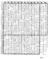
- Figure 1 shows a unified matrix of the two RM codes mentioned above.
- the matrix is built so that columns 2 to 6 are row permutation of columns 2, 3, 5, 9 and 17 from the Hadamard matrix.
- the particular Hadamard matrix concerned has a size of 32 to give a basis of 5 for the vector space.
- In the first column all the values are 1’s.
- the selection of such columns is important to ensure a good codeword (with better Hamming distance properties) .
- the unique matrix design allows for simple encoding by matrix multiplication and Maximum Likelihood (ML) decoding based on Inverse Fast Hadamard Transform (IFHT) .
- ML Maximum Likelihood
- IFHT Inverse Fast Hadamard Transform
- K represents the number of uncoded bits.
- N represents the number of coded bits.
- H 32, i : M i+1 represents column i of the generation matrix, which is a permutation of the Hadamard matrix and a part of the first order RM.
- E i : M i+7 represents column i+6 of the generation matrix, which is a part of the Extension for second order RM.
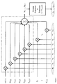
- the RM encoder acts simply like a matrix multiplication with the uncoded bits’vector.
- the encoder structure is shown in figure 2.
- code index n is converted into binary form (a 0 a 1 a 2 a 3 a 4 a 5 ) 2 then code becomes:
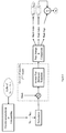
- the RM code can be decoded by ML decoding based on IFHT with low complexity.
- the LLRs of received symbols are accumulated or zero-padded to be length B and then permuted the same way as the generation matrix is permuted in the standard related to Hadamard matrix having a size of 32.
- first order RM code (up to 6 bits) , the process is as follows: a correlation peak index with Hadamard is obtained to find a 1 , ..., a 5 (binary representation of peak index) . Determination of a 0 is made according to peak’s sign (and summation of a 1 , ..., a 5 modulo 2) .
- the complexity for decoding K bits is 5*32 for the first order RM decode and 2 (K-6) * (5*32) for the second order RM decoder.
- RM code In the context of New Radio, RM code has been shown to outperform polar codes with a payload of less than 12 bits. However, it is likely that RM codes will underperform relative to repetition/simplex codes for less than or equal to 2 bits in the payload. Accordingly, RM code is likely to be adopted for New Radio for payload sizes of between 3 to 11 bits.
- a number of proposals have been suggested for RM code design in New Radio. These include a modified generation matrix with an improved minimum hamming distance, a Golay-based code for lower complexity, and a methodology using a priori information at the decoder to improve performance. No proposals to date have taken into consideration a shorter codeword scenario, where the codeword is punctured to fit a limited amount of physical resource elements.
- LTE RM codeword would be an extension by repetition as in LTE. In LTE this repetition is affected by a circular buffer rate matching with puncturing.
- the RM codeword may become punctured or truncated at the end.
- Such puncturing or truncation may lead to a decoding ambiguity that may severely degrade the Block Error Rate (BLER) performance; decoding ambiguity occurs when there are multiple peaks with about same height in the ML decoding process and without an error detection code there is no way of knowing which peak is the correct peak.
- BLER Block Error Rate
- This decoding ambiguity already happens in LTE when Uplink Control Indicators (UCIs) are transmitted on PUSCH and interleaved with the Transport Blocks (TBs) .
- UCIs Uplink Control Indicators
- REs resource elements
- CQI/PMI Channel Quality Information /Precoding Matrix Indicator
- RI Rank Indicator
- HARQ-ACK Hybrid automatic repeat request acknowledgement
- PUCCH Format 3 PUCCH Format 3
- PF3 PUCCH Format 3
- Each encoder produces a 32 bits codeword and each codeword is then truncated to 24 bits. For a codeword size of 24 bits there is no decoding ambiguity, however for 16 bits this does occur and prevent the design of three interleaved RM encoders for higher coding rate and higher spectral efficiency.
- the RM encoder can be looked at as a matrix multiplication (with the uncoded bits’vector) and the codeword truncation at the end is mathematically equivalent to multiplication with a submatrix (rows 1 to N) of the generation matrix given in the standard to get b 0 , ..., b N-1 .
- a shifted truncation could be a selection of b ⁇ , ..., b N-1+ ⁇ which equals a multiplication with a shifted submatrix (rows 1+ ⁇ to N+ ⁇ ) .
- the adaptation of the RM decoder occurs before the log likelihood ratio (LLR) permutation step.
- Decoding ambiguity happens when there is more than a single peak in the ML decoding process; either for the first order correlation (i.e. several peak indices) and/or for the second order selection of highest peak amongst all possible masks (i.e. several mask indices) . With the absence of an error detection code there is no way of knowing which peak is the correct peak.
- the shifted submatrix should fulfil several conditions. More precisely, in all scenarios of (K, N) with LTE-RM decoding ambiguity, the rank of the submatrix is lower than K (there are linearly dependent columns) .
- the present invention is seeking to solve at least some of the outstanding problems in this domain.
- a method for enabling a wireless communications device to access services provided by a Radio Access Network in a communications system operating a Reed-Muller coding process, wherein a communication has a required codeword of size B that is punctured to a codeword of size N the method comprising: rate matching with a shifted puncturing scheme having a predetermined shift ⁇ to obtain a predetermined output bit sequence capable of resolving any decoding ambiguity.
- the predetermined shift determined by at least one of a given set of (K, N, ⁇ ) ; a dynamic calculated ⁇ according to specific criteria for (K, N) ; and dynamic signalling of ⁇ for (K, N) .
- a codeword comprises N bits from K uncoded bits.
- the shifted puncturing scheme can be applied by selecting a row-shifted submatrix from a Reed-Muller code generation matrix to produce the codeword; wherein the shift can be used to resolve decoding ambiguity.
- the shift ⁇ can be determined according to
- the shifted puncturing scheme may repeat the prominent part of the codeword more times; wherein the shift can be used to improve the decoding performance.
- the shift ⁇ is determined such that the submatrix has linearly independent columns such that the submatrix rank equals K.
- the shift ⁇ is determined such that a plurality of first order columns of a permuted submatrix are highly correlated with a Hadamard transformation to give a single peak and the first order columns comprise columns 1 to 6.
- the shift ⁇ is determined such that a plurality of second order columns of the permuted submatrix which are the least correlated with a Hadamard transformation amongst the possible shifts, such that multiplication of a correct mask index with a second order matrix extension is able to become highly correlative with Hadamard to give a single peak, and wherein the second order columns are columns 7 to K.
- guidelines are used to determine a best shift selection so that a single peak is derivable in the decoding process for determining a mask index such that second order columns of the permuted submatrix when correlated with a Hadamard transformation give a minimal average peaks’height and a minimal average peaks’count.
- down-selection of the shift is carried out such that a matrix rank is the strongest.
- a criterion to evaluate the strength of the matrix rank comprises maximal summation of the submatrix singular values, given by the singular value decomposition (SVD) .
- multiple ⁇ shifts are used to resolve the decoding ambiguity.
- multiple interleaved RM codewords may be used to support higher coding rates and higher spectral efficiency for, but not only, the small block lengths in NR.
- the method is capable of being applied to an extended PUCCH format.
- the Radio Access Network is a New Radio/5G network.
- a base station or a user equipment, UE, apparatus adapted to perform the method of another aspect of the present invention.
- a non-transitory computer readable medium having computer readable instructions stored thereon for execution by a processor to perform the method of another aspect of the present invention.
- the non-transitory computer readable medium may comprise at least one from a group consisting of: a hard disk, a CD-ROM, an optical storage device, a magnetic storage device, a Read Only Memory, a Programmable Read Only Memory, an Erasable Programmable Read Only Memory, EPROM, an Electrically Erasable Programmable Read Only Memory and a Flash memory.
- Figure 1 is an LTE-RM generation matrix, according to the prior art.
- Figure 2 is an LTE-RM encoder structure according to the prior art.
- Figure 3 is an LTE-RM decoder structure according to the prior art.
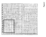
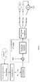
- Figure 4 is an RM generation matrix showing a shifted submatrix selection, according to an embodiment of the present invention.
- Figure 5 is an RM encoder, according to an embodiment of the present invention.
- Figure 6 is an RM decoder, according to an embodiment of the present invention.
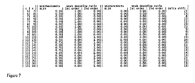
- Figure 7 is a BLER table, according to an embodiment of the present invention.
- Figure 8 is a graph of BLER performance, according to an embodiment of the present invention.
- This invention provides a way of avoiding decoding ambiguity derived from a required codeword, such as a RM codeword puncturing when the available amount of PHY resource elements is limited. As a result the link performance is improved.
- RM codes are mainly used for UL control (reports of HARQ-ACK, CQI/PMI and RI) , the transmission gets more reliable and the gNB can better adapt the link accordingly and eventually improve the overall network performance.
- the penalty of not using this invention would be link degradation and/or scheduling limitations.
- this invention supports higher coding rates and higher spectral efficiency for the small block lengths in NR.
- the invention can be applied to all channels which are using RM coding.
- An advantage of this invention is that the BLER performance is significantly improved in cases where the available amount of PHY resource elements is limited and the RM codeword is therefore punctured/truncated. As a result, in the case of UCI the link adaptation performance is improved. The complexity of both encoder and decoder remains the same, with minor modifications for the rate matching.
- the invention provides a way of avoiding decoding ambiguity derived from RM codeword puncturing/truncation when the available amount of PHY resource elements is limited. This is achieved by means of a shifted puncturing/truncation process.
- the shift ⁇ is determined to fulfil some or all of the following criteria: (i) Submatrix rank equals K. There should be no dependent columns (all columns should be linearly independent) . (ii) Each first order column of the permuted submatrix when correlated with Hadamard produces a single peak (the first order columns are columns 1 to 6) . (iii) The second order columns of the permuted submatrix are the least correlative to Hadamard amongst all possible shifts (the second order columns are columns 7 to K) , so that only multiplication of the correct mask index with the second order matrix extension would become correlative with Hadamard.
- the present invention relates to a ⁇ shift process (either a shifted puncturing scheme or equivalently a shifted submatrix for a shortened codeword) .
- a ⁇ shift process (either a shifted puncturing scheme or equivalently a shifted submatrix for a shortened codeword) .
- the specific steps are given by way of example and other relevant steps are also possible. Multiple ⁇ shifts may alternatively be used to resolve the decoding ambiguity.
- the shift could be predetermined by a given set or calculated dynamically or signalled dynamically.
- the former option is preferable.
- the submatrix selection can be made in any appropriate manner that follows the required “shifted rate matching/puncturing procedure” discussed herein.
- the un-shifted submatrix obviously contains dependent columns, while the shifted submatrix has a rank equals to K. This is not the optimal selection for the shift ⁇ and is given as way of example for resolving a decoding ambiguity.
- CMOS complementary metal-oxide-semiconductor
- N the codeword
- the present invention solves the decoding ambiguity brought about by this situation by making use of a shifted submatrix of the generation matrix (rows 1+ ⁇ to N+ ⁇ and columns 1 to K for a codeword of size N and K uncoded bits) .
- This is essentially mathematically equivalent to applying a shifted puncturing to the codeword of size B after the RM coding to support a codeword of size N.
- the modified encoding/decoding schemes are illustrated in figure 5 and 6 respectively and are each used to capture where the shift ⁇ is observed.
- shifted rate matching is mathematically equivalent to multiplication with a shifted submatrix of the RM encoder.
- the repetition may occur by using a circular buffer rate matching with puncturing.
- the received LLRs are accumulated or zero-padded to be of a length B and circularly shifted by - ⁇ prior to the permutation step. This is essentially a reverse operation in the decoder to the shifted rate matching in the encoder, so the encoder and decoder are aligned.
- the BLER and weak decoding ratios are given for the specified shift in the right most column. It is noted that all decoding ambiguities are resolved with the use of the present invention as, the weak decoding ratio for each previously bad combination of (K, N) is reduced from 1 to 0 and BLER is reduced to 0, which is an indication of perfect decoding.
- the value 1 represents a case where, in all tests more than one peak was detected; and 0 represents a case where, in all tests no multiple peaks were detected.
- N ⁇ B with the present invention a single RM code can be supported. Multiple-RM encoders may also be supported with a shifted truncation to support higher code rates for higher spectral efficiency. Generally, for a combined codeword of N bits with K uncoded bits, using the present invention, M encoders (having about K/M uncoded bits and N/M coded bits) can be supported. In this situation, where N/M ⁇ B without constraints due to decoding ambiguity as in the original LTE-RM code rate matching scheme, higher coding rates and higher spectral efficiency can be supported for the small block lengths in NR.
- Each encoder produces a 32 bit codeword and each codeword is then truncated to 24 bits.
- the present invention could be applicable for LTE if it is applied in a backwardly compatible manner. This could be achieved by adding a capability signaling from the UE for ‘RM enhanced puncturing’ . In this way the eNB would be able to configure a UE which is capable of enhanced RM puncturing to use the new puncturing with a Radio Resource Control (RRC) configuration (e.g., as part of physical layer configuration in RRCConnectionReconfiguration message) which would mean that the UE is then compatible with the new process and method of the present invention.
- RRC Radio Resource Control
- any of the devices or apparatus that form part of the network may include at least a processor, a storage unit and a communications interface, wherein the processor unit, storage unit, and communications interface are configured to perform the method of any aspect of the present invention. Further options and choices are described below.
- the signal processing functionality of the embodiments of the invention especially the gNB and the UE may be achieved using computing systems or architectures known to those who are skilled in the relevant art.
- Computing systems such as, a desktop, laptop or notebook computer, hand-held computing device (PDA, cell phone, palmtop, etc. ) , mainframe, server, client, or any other type of special or general purpose computing device as may be desirable or appropriate for a given application or environment can be used.
- the computing system can include one or more processors which can be implemented using a general or special-purpose processing engine such as, for example, a microprocessor, microcontroller or other control module.
- the computing system can also include a main memory, such as random access memory (RAM) or other dynamic memory, for storing information and instructions to be executed by a processor. Such a main memory also may be used for storing temporary variables or other intermediate information during execution of instructions to be executed by the processor.
- the computing system may likewise include a read only memory (ROM) or other static storage device for storing static information and instructions for a processor.
- ROM read only memory
- the computing system may also include an information storage system which may include, for example, a media drive and a removable storage interface.
- the media drive may include a drive or other mechanism to support fixed or removable storage media, such as a hard disk drive, a floppy disk drive, a magnetic tape drive, an optical disk drive, a compact disc (CD) or digital video drive (DVD) read or write drive (R or RW) , or other removable or fixed media drive.
- Storage media may include, for example, a hard disk, floppy disk, magnetic tape, optical disk, CD or DVD, or other fixed or removable medium that is read by and written to by media drive.
- the storage media may include a computer-readable storage medium having particular computer software or data stored therein.
- an information storage system may include other similar components for allowing computer programs or other instructions or data to be loaded into the computing system.
- Such components may include, for example, a removable storage unit and an interface, such as a program cartridge and cartridge interface, a removable memory (for example, a flash memory or other removable memory module) and memory slot, and other removable storage units and interfaces that allow software and data to be transferred from the removable storage unit to computing system.
- the computing system can also include a communications interface.
- a communications interface can be used to allow software and data to be transferred between a computing system and external devices.
- Examples of communications interfaces can include a modem, a network interface (such as an Ethernet or other NIC card) , a communications port (such as for example, a universal serial bus (USB) port) , a PCMCIA slot and card, etc.
- Software and data transferred via a communications interface are in the form of signals which can be electronic, electromagnetic, and optical or other signals capable of being received by a communications interface medium.
- computer program product may be used generally to refer to tangible media such as, for example, a memory, storage device, or storage unit.
- These and other forms of computer-readable media may store one or more instructions for use by the processor comprising the computer system to cause the processor to perform specified operations.
- Such instructions generally referred to as ‘computer program code’ (which may be grouped in the form of computer programs or other groupings) , when executed, enable the computing system to perform functions of embodiments of the present invention.
- the code may directly cause a processor to perform specified operations, be compiled to do so, and/or be combined with other software, hardware, and/or firmware elements (e.g., libraries for performing standard functions) to do so.
- the non-transitory computer readable medium may comprise at least one from a group consisting of: a hard disk, a CD-ROM, an optical storage device, a magnetic storage device, a Read Only Memory, a Programmable Read Only Memory, an Erasable Programmable Read Only Memory, EPROM, an Electrically Erasable Programmable Read Only Memory and a Flash memory
- the software may be stored in a computer-readable medium and loaded into computing system using, for example, removable storage drive.
- a control module in this example, software instructions or executable computer program code
- the processor in the computer system when executed by the processor in the computer system, causes a processor to perform the functions of the invention as described herein.
- inventive concept can be applied to any circuit for performing signal processing functionality within a network element. It is further envisaged that, for example, a semiconductor manufacturer may employ the inventive concept in a design of a stand-alone device, such as a microcontroller of a digital signal processor (DSP) , or application-specific integrated circuit (ASIC) and/or any other sub-system element.
- DSP digital signal processor
- ASIC application-specific integrated circuit
- aspects of the invention may be implemented in any suitable form including hardware, software, firmware or any combination of these.
- the invention may optionally be implemented, at least partly, as computer software running on one or more data processors and/or digital signal processors or configurable module components such as FPGA devices.
- the elements and components of an embodiment of the invention may be physically, functionally and logically implemented in any suitable way. Indeed, the functionality may be implemented in a single unit, in a plurality of units or as part of other functional units.
Landscapes
- Engineering & Computer Science (AREA)
- Computer Networks & Wireless Communication (AREA)
- Signal Processing (AREA)
- Physics & Mathematics (AREA)
- Probability & Statistics with Applications (AREA)
- Theoretical Computer Science (AREA)
- Error Detection And Correction (AREA)
- Mobile Radio Communication Systems (AREA)
Abstract
A method for enabling a wireless communications device to access services provided by a Radio Access Network in a communications system operating a Reed-Muller coding process, wherein a communication has a required codeword of size B that is punctured to a codeword of size N, the method comprising: rate matching with a shifted puncturing scheme having a predetermined shift Δ to obtain a predetermined output bit sequence capable of resolving any decoding ambiguity.
Description
Embodiments of the present invention generally relate to wireless communications system and in particular to devices and methods for enabling a wireless communications device, such as a User Equipment (UE) or mobile device to access a Radio Access Technology (RAT) or Radio Access Network (RAN) , particularly but nor exclusively to a communications system using Reed-Muller (RM) codes.
Wireless communication systems, such as the third-generation (3G) of mobile telephone standards and technology are well known. Such 3G standards and technology have been developed by the Third Generation Partnership Project (3GPP) . The 3rd generation of wireless communications has generally been developed to support macro-cell mobile phone communications. Communications systems and networks have been developed towards a broadband and mobile system.
The 3rd Generation Partnership Project has developed the so-called Long Term Evolution (LTE) system, namely, an Evolved Universal Mobile Telecommunications System Territorial Radio Access Network, (E-UTRAN) , for a mobile access network where one or more macro-cells are supported by a base station known as an eNodeB or eNB (evolved NodeB) . More recently, LTE is evolving further towards the so-called 5G or NR (new radio) systems where one or more cells are supported by a base station known as a gNB (generalized NodeB) .
RM codes are used in New Radio for very small block lengths without an error detection code. RM codes are a family of linear error correcting codes used in communications. RM codes belong to classes of locally testable codes and locally decodable codes, which is why they are useful in design of communications related applications.
A number of studies have been made of the relevance of RM coding to the domains of LTE and New Radio. RM codes are generally to be adopted for specific payload sizes but are unlikely to be of relevance when additional error code detection (such as for example Cyclic Redundancy Check CRC) are to be used.
As a result of the intrinsic benefits of RM coding, New Radio are now looking at this technology to use in control coding for small block lengths without error detection coding. As a result it has been determined that the use of RM coding might well be relevant for payload sizes of between 3 and 11 bits.
At present RM codes are used in LTE for a number of different functions. A first RM code design is used for uplink control information on Physical Uplink Shared Channel (PUSCH) and Physical Uplink Control Channel (PUCCH) format 3, given in 3GPP TS 36.212 Release 13 Table 5.2.2.6.4-1 ( “Basis sequences for (32, O) code” ) for up to 11 uncoded bits and 32 coded bits. A second RM code is used for the uplink control information on PUCCH excluding format 3, given in 3GPP TS 36.212 Release 13 Table 5.2.3.3-1 ( “Basis sequences for (20, A) code” ) for up to 13 uncoded bits and 20 coded bits.
Figure 1 shows a unified matrix of the two RM codes mentioned above. In LTE there are two matrices given in “3GPP TS 36.212 Release 13” by: Table 5.2.2.6.4-1: Basis sequences for (32, O) code; K <= 11; and Table 5.2.3.3-1: Basis sequences for (20, A) code; K <=13.
These two matrices coincide values in the overlapping area; therefore the figure shows just only one bigger matrix to include the two matrices together. The M
i, n values are the same for i <= 19 and n <= 10. The matrix is built so that columns 2 to 6 are row permutation of columns 2, 3, 5, 9 and 17 from the Hadamard matrix. The particular Hadamard matrix concerned has a size of 32 to give a basis of 5 for the vector space. In the first column all the values are 1’s. The other columns represent the addition due to the extension from the first order RM code (up to 6 bits) to the second order RM code (up to A bits where A = 11 or 13 depending on the table) . The selection of such columns is important to ensure a good codeword (with better Hamming distance properties) .
The unique matrix design allows for simple encoding by matrix multiplication and Maximum Likelihood (ML) decoding based on Inverse Fast Hadamard Transform (IFHT) .
The notations used in this application are as follows: K: represents the number of uncoded bits. N: represents the number of coded bits. H
32, i: M
i+1, represents column i of the generation matrix, which is a permutation of the Hadamard matrix and a part of the first order RM. E
i: M
i+7, represents column i+6 of the generation matrix, which is a part of the Extension for second order RM.
The RM encoder acts simply like a matrix multiplication with the uncoded bits’vector. The encoded block is denoted by b
0, b
1, ..., b
B-1 where B = 20 (or 32) and b
i = (sum {a
n*M
i, n} over n from 0 to A-1) mod 2 where i = 0, 1, ..., B-1 and A = K. The RM codeword is extended by repetition (a circular buffer rate matching with puncturing) to give a codeword of size N: c
i = b
i mod B, where i = 0, 1, ..., N-1. The encoder structure is shown in figure 2.
In the encoder, if code index n is converted into binary form (a
0a
1a
2a
3a
4a
5)
2 then code becomes:
a
5*H
32, 17+a
4*H
32, 9+a
3*H
32, 5+a
2*H
32, 3+a
1*H
32, 2+a
0*all 1’s.
In addition, for more than 6 bits the following applies:
a
A-1*E
A-6+...+a
9*E
4+a
8*E
3+a
7*E
2+a
6*E
1+
a
5*H
32, 17+a
4*H
32, 9+a
3*H
32, 5+a
2*H
32, 3+a
1*H
32, 2+a
0*all 1’s.
The RM code can be decoded by ML decoding based on IFHT with low complexity. The LLRs of received symbols are accumulated or zero-padded to be length B and then permuted the same way as the generation matrix is permuted in the standard related to Hadamard matrix having a size of 32.
A typical decoder structure is illustrated in figure 3
For first order RM code (up to 6 bits) , the process is as follows: a correlation peak index with Hadamard is obtained to find a
1, ..., a
5 (binary representation of peak index) . Determination of a
0 is made according to peak’s sign (and summation of a
1, ..., a
5 modulo 2) .
For second order RM code (above 6 bits) , the process is as follows: an exhaustive search is made over all possible options: 2
(A-6) masks of length of 32 are derived by the multiplication of the mask index (in binary representation) with the second order matrix extension. These masks scramble the LLRs prior to correlation with
Hadamard. Correlation with Hadamard is calculated for all masks and the correlation peaks are stored for comparison. A mask index with highest peak gives a
6, ..., a
A-1 (binary representation of mask index) . The highest peak’s index gives a
1, ..., a
5 (binary representation of peak index) . Determination of a
0 according to peak’s sign (and summation of a
1, ..., a
5 modulo 2) is made.
The complexity for decoding K bits is 5*32 for the first order RM decode and 2
(K-6) * (5*32) for the second order RM decoder.
In the context of New Radio, RM code has been shown to outperform polar codes with a payload of less than 12 bits. However, it is likely that RM codes will underperform relative to repetition/simplex codes for less than or equal to 2 bits in the payload. Accordingly, RM code is likely to be adopted for New Radio for payload sizes of between 3 to 11 bits. A number of proposals have been suggested for RM code design in New Radio. These include a modified generation matrix with an improved minimum hamming distance, a Golay-based code for lower complexity, and a methodology using a priori information at the decoder to improve performance. No proposals to date have taken into consideration a shorter codeword scenario, where the codeword is punctured to fit a limited amount of physical resource elements.
It seems likely that New Radio requires a codeword size that is not supported by the LTE RM code. This would mean that the LTE RM codeword would be an extension by repetition as in LTE. In LTE this repetition is affected by a circular buffer rate matching with puncturing.
In the case where physical resources are limited, a similar practice will take place and the RM codeword may become punctured or truncated at the end. Such puncturing or truncation may lead to a decoding ambiguity that may severely degrade the Block Error Rate (BLER) performance; decoding ambiguity occurs when there are multiple peaks with about same height in the ML decoding process and without an error detection code there is no way of knowing which peak is the correct peak. This decoding ambiguity already happens in LTE when Uplink Control Indicators (UCIs) are transmitted on PUSCH and interleaved with the Transport Blocks (TBs) . In this case only a few resource elements (REs) are allocated to convey the Channel Quality Information /Precoding Matrix Indicator (CQI/PMI) and/or Rank Indicator (RI) and/or Hybrid automatic repeat request acknowledgement (HARQ-ACK) .
Another example of this puncturing and truncation can take place in PUCCH Format 3 (PF3) where a combined codeword of 48 bits is allocated and two interleaved RM encoders are used to support the relevant number of uncoded bits 11 <K <= 21 (K/2 bits per codeword) . Each encoder produces a 32 bits codeword and each codeword is then truncated to 24 bits. For a codeword size of 24 bits there is no decoding ambiguity, however for 16 bits this does occur and prevent the design of three interleaved RM encoders for higher coding rate and higher spectral efficiency.
The RM encoder can be looked at as a matrix multiplication (with the uncoded bits’vector) and the codeword truncation at the end is mathematically equivalent to multiplication with a submatrix (rows 1 to N) of the generation matrix given in the standard to get b
0, ..., b
N-1. A shifted truncation could be a selection of b
Δ, ..., b
N-1+Δ which equals a multiplication with a shifted submatrix (rows 1+Δ to N+Δ) . The adaptation of the RM decoder occurs before the log likelihood ratio (LLR) permutation step.
Decoding ambiguity happens when there is more than a single peak in the ML decoding process; either for the first order correlation (i.e. several peak indices) and/or for the second order selection of highest peak amongst all possible masks (i.e. several mask indices) . With the absence of an error detection code there is no way of knowing which peak is the correct peak.
In order to avoid such decoding ambiguity the shifted submatrix should fulfil several conditions. More precisely, in all scenarios of (K, N) with LTE-RM decoding ambiguity, the rank of the submatrix is lower than K (there are linearly dependent columns) . The present invention is seeking to solve at least some of the outstanding problems in this domain.
Summary
This Summary is provided to introduce a selection of concepts in a simplified form that are further described below in the Detailed Description. This Summary is not intended to identify key features or essential features of the claimed subject matter, nor is it intended to be used as an aid in determining the scope of the claimed subject matter.
According to a first aspect of the present invention there is provided a method for enabling a wireless communications device to access services provided by a Radio Access Network in a communications system operating a Reed-Muller coding process, wherein a communication has a required codeword of size B that is punctured to a codeword of size N, the method comprising: rate matching with a shifted puncturing scheme having a predetermined shift Δ to obtain a predetermined output bit sequence capable of resolving any decoding ambiguity.
Preferably, the predetermined output bit sequence is c
i = b
(i+Δ) mod B, where i = 0, 1, ..., N-1.
Preferably, the predetermined shift determined by at least one of a given set of (K, N, Δ) ; a dynamic calculated Δ according to specific criteria for (K, N) ; and dynamic signalling ofΔ for (K, N) .
Preferably, a codeword comprises N bits from K uncoded bits.
Preferably, for N < B, the shifted puncturing scheme can be applied by selecting a row-shifted submatrix from a Reed-Muller code generation matrix to produce the codeword; wherein the shift can be used to resolve decoding ambiguity.
Preferably, where N > B the shift Δ can be determined according to


Preferably, for N > B, the shifted puncturing scheme may repeat the prominent part of the codeword
 more times; wherein the shift can be used to improve the decoding performance.
Preferably, the shift Δ is determined such that the submatrix has linearly independent columns such that the submatrix rank equals K.
Preferably, the shift Δ is determined such that a plurality of first order columns of a permuted submatrix are highly correlated with a Hadamard transformation to give a single peak and the first order columns comprise columns 1 to 6.
Preferably, the shift Δ is determined such that a plurality of second order columns of the permuted submatrix which are the least correlated with a Hadamard transformation amongst the possible shifts, such that multiplication of a correct mask index with a second order matrix extension is able to become highly correlative with Hadamard to give a single peak, and wherein the second order columns are columns 7 to K.
Preferably, guidelines are used to determine a best shift selection so that a single peak is derivable in the decoding process for determining a mask index such that second order columns of the permuted submatrix when correlated with a Hadamard transformation give a minimal average peaks’height and a minimal average peaks’count.
Preferably, down-selection of the shift is carried out such that a matrix rank is the strongest.
Preferably, a criterion to evaluate the strength of the matrix rank comprises maximal summation of the submatrix singular values, given by the singular value decomposition (SVD) .
Preferably, multiple Δ shifts are used to resolve the decoding ambiguity.
Preferably, multiple interleaved RM codewords may be used to support higher coding rates and higher spectral efficiency for, but not only, the small block lengths in NR. Preferably, the method is capable of being applied to an extended PUCCH format. Preferably, the Radio Access Network is a New Radio/5G network.
According to a second aspect of the present invention there is provided a base station or a user equipment, UE, apparatus adapted to perform the method of another aspect of the present invention.
According to a third aspect of the present invention there is provided a non-transitory computer readable medium having computer readable instructions stored thereon for execution by a processor to perform the method of another aspect of the present invention.
The non-transitory computer readable medium may comprise at least one from a group consisting of: a hard disk, a CD-ROM, an optical storage device, a magnetic storage device, a Read Only Memory, a Programmable Read Only Memory, an Erasable Programmable Read Only Memory, EPROM, an Electrically Erasable Programmable Read Only Memory and a Flash memory.
Further details, aspects and embodiments of the invention will be described, by way of example only, with reference to the drawings. Elements in the figures are illustrated for simplicity and clarity and have not necessarily been drawn to scale.
Like reference numerals have been included in the respective drawings to ease understanding.
Figure 1 is an LTE-RM generation matrix, according to the prior art.
Figure 2 is an LTE-RM encoder structure according to the prior art.
Figure 3 is an LTE-RM decoder structure according to the prior art.
Figure 4 is an RM generation matrix showing a shifted submatrix selection, according to an embodiment of the present invention.
Figure 5 is an RM encoder, according to an embodiment of the present invention.
Figure 6 is an RM decoder, according to an embodiment of the present invention.
Figure 7 is a BLER table, according to an embodiment of the present invention.
Figure 8 is a graph of BLER performance, according to an embodiment of the present invention.
Detailed description of the preferred embodiments
Those skilled in the art will recognise and appreciate that the specifics of the examples described are merely illustrative of some embodiments and that the teachings set forth herein are applicable in a variety of alternative settings.
This invention provides a way of avoiding decoding ambiguity derived from a required codeword, such as a RM codeword puncturing when the available amount of PHY resource elements is limited. As a result the link performance is improved. In addition, since RM codes are mainly used for UL control (reports of HARQ-ACK, CQI/PMI and RI) , the transmission gets more reliable and the gNB can better adapt the link accordingly and eventually improve the overall network performance. The penalty of not using this invention would be link degradation and/or scheduling limitations.
The proposed design significantly improves the block error rate (BLER) performance. However, both encoder and decoder should know the applied Δ. This could be determined, for example, by a predefined given set of shifts (K, N, Δ) . At least for LTE-RM generation matrix, it is possible to find such a Δ that resolves the decoding ambiguity for all combinations of (K, N) .
Further, this invention supports higher coding rates and higher spectral efficiency for the small block lengths in NR. The invention can be applied to all channels which are using RM coding.
An advantage of this invention is that the BLER performance is significantly improved in cases where the available amount of PHY resource elements is limited and the RM codeword is therefore punctured/truncated. As a result, in the case of UCI the link adaptation performance is improved. The complexity of both encoder and decoder remains the same, with minor modifications for the rate matching.
As previously mentioned, the invention provides a way of avoiding decoding ambiguity derived from RM codeword puncturing/truncation when the available amount of PHY resource elements is limited. This is achieved by means of a shifted puncturing/truncation process.
The shift Δ is determined to fulfil some or all of the following criteria: (i) Submatrix rank equals K. There should be no dependent columns (all columns should be linearly independent) . (ii) Each first order column of the permuted submatrix when correlated with Hadamard produces a single peak (the first order columns are columns 1 to 6) . (iii) The second order columns of the permuted submatrix are the least correlative to Hadamard amongst all possible shifts (the second order columns are columns 7 to K) , so that only multiplication of the correct mask index with the second order matrix extension would become correlative with Hadamard. For example, by selecting minimal average peaks’height and minimal average peaks’count, where the average is on the K-6 columns. (iv) Finally, among all shifts that fulfil some or all of the above criteria, the shift is chosen to give maximal summation of the submatrix singular values, given by the singular value decomposition (SVD) to assure strongest matrix rank.
Thus in its broadest sense the present invention relates to a Δ shift process (either a shifted puncturing scheme or equivalently a shifted submatrix for a shortened codeword) . The specific steps are given by way of example and other relevant steps are also possible. Multiple Δ shifts may alternatively be used to resolve the decoding ambiguity.
The shift could be predetermined by a given set or calculated dynamically or signalled dynamically. The former option is preferable.
Figure 4 illustrates a shifted submatrix selection with Δ = 1 for K = 6 and N = 10. The submatrix selection can be made in any appropriate manner that follows the required “shifted rate matching/puncturing procedure” discussed herein. The un-shifted submatrix obviously contains dependent columns, while the shifted submatrix has a rank equals to K. This is not the optimal selection for the shift Δ and is given as way of example for resolving a decoding ambiguity.
Known RM coding uses a generation matrix to produce a codeword of size B. The codeword is then circularly repeated and punctured /truncated at the end to match size N. In case N < B, the present invention solves the decoding ambiguity brought about by this situation by making use of a shifted submatrix of the generation matrix (rows 1+Δ to N+Δ and columns 1 to K for a codeword of size N and K uncoded bits) . This is essentially mathematically equivalent to applying a shifted puncturing to the codeword of size B after the RM coding to support a codeword of size N. As a result, it can appear that there is no change in the RM code (since there is no change in the generation matrix) . However, a different rate matching is applied which is a shifted rate matching. This can be further extended to deal with N > B: in this case there is no decoding ambiguity, however the prominent part of the codeword (bits 1+Δ to

 of the RM codeword of size B) is repeated more times due to the circular buffer rate matching with shifted puncturing scheme: c
i = b
(i+Δ) mod B, where i = 0, 1, ..., N-1. This can thus further improve the BLER.
of the RM codeword of size B) is repeated more times due to the circular buffer rate matching with shifted puncturing scheme: c
i = b
(i+Δ) mod B, where i = 0, 1, ..., N-1. This can thus further improve the BLER.
The modified encoding/decoding schemes are illustrated in figure 5 and 6 respectively and are each used to capture where the shift Δ is observed.
In the encoder, the RM codeword is extended by repetition to give a codeword of size N with a shift Δ, such that: c
i = b
(i+Δ) mod B, where i = 0, 1, ..., N-1. It should be noted that shifted rate matching is mathematically equivalent to multiplication with a shifted submatrix of the RM encoder. The repetition may occur by using a circular buffer rate matching with puncturing.
In the decoder, the received LLRs are accumulated or zero-padded to be of a length B and circularly shifted by -Δ prior to the permutation step. This is essentially a reverse operation in the decoder to the shifted rate matching in the encoder, so the encoder and decoder are aligned.
Simulation results of all possible codewords with K uncoded bits and N coded bits for (K, N) configurations in which decoding ambiguity occur (without any noise added) , are given in the table shown in figure 7.
The table shows the high BLER in the relevant cases. If there is a single peak then BLER should be 0. However, when a decoding ambiguity exists, there are more than one peak. In case of two peaks, BLER equals 1/2=0.5 and for four peaks BLER equals 1/4=0.25. Since the table in figure 7 shows results in perfect conditions (no noise or channel are added) all BLER values are expected to equal 0, which means a one-to-one correspondence between the uncoded bits and the coded bits. A weak decoding ratio gives a number of cases where there are more than one peak divided by the overall number of tests (in this case 2
K tests) , separately for the first and second order stages. On the left of the table, the BLER and weak decoding ratios are given for no shift (Δ = 0) . On the right the BLER and weak decoding ratios are given for the specified shift in the right most column. It is noted that all decoding ambiguities are resolved with the use of the present invention as, the weak decoding ratio for each previously bad combination of (K, N) is reduced from 1 to 0 and BLER is reduced to 0, which is an indication of perfect decoding. In the table, the value 1 represents a case where, in all tests more than one peak was detected; and 0 represents a case where, in all tests no multiple peaks were detected.
This is further shown in the graph of figure 8, which illustrates the BLER curves as a function of Signal to Noise Ratio (SNR) for the cases shown, and relate to Binary Phase Shift Keying (BPSK) modulation and Additive White Gaussian Noise (AWGN) channel. A significant BLER improvement is observed using the enhanced RM code of the present invention.
In the situation where N > B the shift Δ can be determined according to

 However, in the situation where N > B the codeword is already fully transmitted, with the proposed shift Δ the prominent part of the codeword is repeated more times. This can further give rise to further BLER improvements.
In the situation where N < B with the present invention, a single RM code can be supported. Multiple-RM encoders may also be supported with a shifted truncation to support higher code rates for higher spectral efficiency. Generally, for a combined codeword of N bits with K uncoded bits, using the present invention, M encoders (having about K/M uncoded bits and N/M coded bits) can be supported. In this situation, where N/M < B without constraints due to decoding ambiguity as in the original LTE-RM code rate matching scheme, higher coding rates and higher spectral efficiency can be supported for the small block lengths in NR.
By way of example, in LTE PUCCH format 3, a combined codeword of 48 bits is allocated and two interleaved RM encoders are used to support 11 < K <= 21 (K/2 bits per codeword) . Each encoder produces a 32 bit codeword and each codeword is then truncated to 24 bits. For a codeword size of 24 bits there is no decoding ambiguity, however for 16 bits there is. Using the present invention, the PF3-like scheme of multiple RM encoders, can be extended to three codewords of 16 bits each and support up to K = 39 bits (with K/3 bits per codeword) with a higher code rate (for higher spectral efficiency) .
The present invention could be applicable for LTE if it is applied in a backwardly compatible manner. This could be achieved by adding a capability signaling from the UE for ‘RM enhanced puncturing’ . In this way the eNB would be able to configure a UE which is capable of enhanced RM puncturing to use the new puncturing with a Radio Resource Control (RRC) configuration (e.g., as part of physical layer configuration in RRCConnectionReconfiguration message) which would mean that the UE is then compatible with the new process and method of the present invention.
Although not shown in detail any of the devices or apparatus that form part of the network may include at least a processor, a storage unit and a communications interface, wherein the processor unit, storage unit, and communications interface are configured to perform the method of any aspect of the present invention. Further options and choices are described below.
The signal processing functionality of the embodiments of the invention especially the gNB and the UE may be achieved using computing systems or architectures known to those who are skilled in the relevant art. Computing systems such as, a desktop, laptop or notebook computer, hand-held computing device (PDA, cell phone, palmtop, etc. ) , mainframe, server, client, or any other type of special or general purpose computing device as may be desirable or appropriate for a given application or environment can be used. The computing system can include one or more processors which can be implemented using a general or special-purpose processing engine such as, for example, a microprocessor, microcontroller or other control module.
The computing system can also include a main memory, such as random access memory (RAM) or other dynamic memory, for storing information and instructions to be executed by a processor. Such a main memory also may be used for storing temporary variables or other intermediate information during execution of instructions to be executed by the processor. The computing system may likewise include a read only memory (ROM) or other static storage device for storing static information and instructions for a processor.
The computing system may also include an information storage system which may include, for example, a media drive and a removable storage interface. The media drive may include a drive or other mechanism to support fixed or removable storage media, such as a hard disk drive, a floppy disk drive, a magnetic tape drive, an optical disk drive, a compact disc (CD) or digital video drive (DVD) read or write drive (R or RW) , or other removable or fixed media drive. Storage media may include, for example, a hard disk, floppy disk, magnetic tape, optical disk, CD or DVD, or other fixed or removable medium that is read by and written to by media drive. The storage media may include a computer-readable storage medium having particular computer software or data stored therein.
In alternative embodiments, an information storage system may include other similar components for allowing computer programs or other instructions or data to be loaded into the computing system. Such components may include, for example, a removable storage unit and an interface, such as a program cartridge and cartridge interface, a removable memory (for example, a flash memory or other removable memory module) and memory slot, and other removable storage units and interfaces that allow software and data to be transferred from the removable storage unit to computing system.
The computing system can also include a communications interface. Such a communications interface can be used to allow software and data to be transferred between a computing system and external devices. Examples of communications interfaces can include a modem, a network interface (such as an Ethernet or other NIC card) , a communications port (such as for example, a universal serial bus (USB) port) , a PCMCIA slot and card, etc. Software and data transferred via a communications interface are in the form of signals which can be electronic, electromagnetic, and optical or other signals capable of being received by a communications interface medium.
In this document, the terms ‘computer program product’ , ‘computer-readable medium’ and the like may be used generally to refer to tangible media such as, for example, a memory, storage device, or storage unit. These and other forms of computer-readable media may store one or more instructions for use by the processor comprising the computer system to cause the processor to perform specified operations. Such instructions, generally referred to as ‘computer program code’ (which may be grouped in the form of computer programs or other groupings) , when executed, enable the computing system to perform functions of embodiments of the present invention. Note that the code may directly cause a processor to perform specified operations, be compiled to do so, and/or be combined with other software, hardware, and/or firmware elements (e.g., libraries for performing standard functions) to do so.
The non-transitory computer readable medium may comprise at least one from a group consisting of: a hard disk, a CD-ROM, an optical storage device, a magnetic storage device, a Read Only Memory, a Programmable Read Only Memory, an Erasable Programmable Read Only Memory, EPROM, an Electrically Erasable Programmable Read Only Memory and a Flash memory
In an embodiment where the elements are implemented using software, the software may be stored in a computer-readable medium and loaded into computing system using, for example, removable storage drive. A control module (in this example, software instructions or executable computer program code) , when executed by the processor in the computer system, causes a processor to perform the functions of the invention as described herein.
Furthermore, the inventive concept can be applied to any circuit for performing signal processing functionality within a network element. It is further envisaged that, for example, a semiconductor manufacturer may employ the inventive concept in a design of a stand-alone device, such as a microcontroller of a digital signal processor (DSP) , or application-specific integrated circuit (ASIC) and/or any other sub-system element.
It will be appreciated that, for clarity purposes, the above description has described embodiments of the invention with reference to a single processing logic. However, the inventive concept may equally be implemented by way of a plurality of different functional units and processors to provide the signal processing functionality. Thus, references to specific functional units are only to be seen as references to suitable means for providing the described functionality, rather than indicative of a strict logical or physical structure or organisation.
Aspects of the invention may be implemented in any suitable form including hardware, software, firmware or any combination of these. The invention may optionally be implemented, at least partly, as computer software running on one or more data processors and/or digital signal processors or configurable module components such as FPGA devices. Thus, the elements and components of an embodiment of the invention may be physically, functionally and logically implemented in any suitable way. Indeed, the functionality may be implemented in a single unit, in a plurality of units or as part of other functional units.
Although the present invention has been described in connection with some embodiments, it is not intended to be limited to the specific form set forth herein. Rather, the scope of the present invention is limited only by the accompanying claims. Additionally, although a feature may appear to be described in connection with particular embodiments, one skilled in the art would recognize that various features of the described embodiments may be combined in accordance with the invention. In the claims, the term ‘comprising’ does not exclude the presence of other elements or steps.
Furthermore, although individually listed, a plurality of means, elements or method steps may be implemented by, for example, a single unit or processor. Additionally, although individual features may be included in different claims, these may possibly be advantageously combined, and the inclusion in different claims does not imply that a combination of features is not feasible and/or advantageous. Also, the inclusion of a feature in one category of claims does not imply a limitation to this category, but rather indicates that the feature is equally applicable to other claim categories, as appropriate.
Furthermore, the order of features in the claims does not imply any specific order in which the features must be performed and in particular the order of individual steps in a method claim does not imply that the steps must be performed in this order. Rather, the steps may be performed in any suitable order. In addition, singular references do not exclude a plurality. Thus, references to ‘a’ , ‘an’ , ‘first’ , ‘second’ , etc. do not preclude a plurality.
Although the present invention has been described in connection with some embodiments, it is not intended to be limited to the specific form set forth herein. Rather, the scope of the present invention is limited only by the accompanying claims. Additionally, although a feature may appear to be described in connection with particular embodiments, one skilled in the art would recognise that various features of the described embodiments may be combined in accordance with the invention. In the claims, the term ‘comprising’ or “including” does not exclude the presence of other elements.
Claims (20)
- A method for enabling a wireless communications device to access services provided by a Radio Access Network in a communications system operating a Reed-Muller coding process, wherein a communication has a required codeword of size B that is punctured to a codeword of size N, the method comprising:rate matching with a shifted puncturing scheme having a predetermined shift Δ to obtain a predetermined output bit sequence capable of resolving any decoding ambiguity.
- The method of claim 1, wherein the predetermined output bit sequence is c i=b (i+Δ) mod B, where i = 0, 1, ..., N-1.
- The method of claim 1 or claim 2, wherein the predetermined shift determined by at least one of a given set of (K, N, Δ) ; a dynamic calculated Δ according to specific criteria for (K, N) ; and dynamic signalling of Δ for (K, N) .
- The method of claim 1 or claims 2, wherein a codeword comprises N bits from K uncoded bits.
- The method of any preceding claim, wherein for N<B, the shifted puncturing scheme can be applied by selecting a row-shifted submatrix from a Reed-Muller code generation matrix to produce the codeword; wherein the shift can be used to resolve decoding ambiguity.
- The method of claim 5, wherein where N > Bthe shift Δ can be determined according to

- The method of any preceding claim, wherein for N>B, the shifted puncturing scheme may repeat the prominent part of the codeword
 more times; wherein the shift can be used to improve the decoding performance.
- The method of any preceding claims wherein the shift Δ is determined such that the submatrix has linearly independent columns such that the submatrix rank equals K.
- The method of any preceding claims wherein the shift Δ is determined such that a plurality of first order columns of a permuted submatrix are highly correlated with a Hadamard transformation to give a single peak and the first order columns comprise columns 1 to 6.
- The method of claim 9, wherein the shift Δ is determined such that a plurality of second order columns of the permuted submatrix which are the least correlated with a Hadamard transformation amongst the possible shifts, such that multiplication of a correct mask index with a second order matrix extension is able to become highly correlative with Hadamard to give a single peak, and wherein the second order columns are columns 7 to K.
- The method of any claim 9 or 10, wherein guidelines are used to determine a best shift selection so that a single peak is derivable in the decoding process for determining a mask index such that second order columns of the permuted submatrix when correlated with a Hadamard transformation give a minimal average peaks’ height and a minimal average peaks’ count.
- The method of any preceding claims wherein down-selection of the shift is carried out such that a matrix rank is the strongest.
- The method of claim 12, wherein a criterion to evaluate the strength of the matrix rank comprises maximal summation of the submatrix singular values, given by the singular value decomposition (SVD) .
- The method of any preceding claims wherein multiple Δ shifts are used to resolve the decoding ambiguity.
- The method of any of the preceding claims, wherein multiple interleaved RM codewords may be used to support higher coding rates and higher spectral efficiency for, but not only, the small block lengths in NR.
- The method of any preceding claim, capable of being applied to an extended PUCCH format.
- The method of any preceding claim wherein the Radio Access Network is a New Radio/5G network.
- A user equipment, UE, apparatus comprising a processor, a storage unit and a communications interface, wherein the processor unit, storage unit, and communications interface are configured to perform the method as claimed in any one of claims 1 to 17.
- A base station, BS, apparatus comprising a processor, a storage unit and a communications interface, wherein the processor unit, storage unit, and communications interface are configured to perform the method as claimed in any one of claims 1 to 17
- A non-transitory computer readable medium having computer readable instructions stored thereon for execution by a processor to perform the method according to any of claims 1 to 17.
Priority Applications (1)
| Application Number | Priority Date | Filing Date | Title |
|---|---|---|---|
| CN201880044353.8A CN110999145B (en) | 2017-08-02 | 2018-08-01 | Improvements in or relating to communications systems using Reed-Muller coding |
Applications Claiming Priority (2)
| Application Number | Priority Date | Filing Date | Title |
|---|---|---|---|
| GB1712420.7 | 2017-08-02 | ||
| GB1712420.7A GB2565111B (en) | 2017-08-02 | 2017-08-02 | Improvement in or relating to communications systems using Reed-Muller codes |
Publications (1)
| Publication Number | Publication Date |
|---|---|
| WO2019024862A1 true WO2019024862A1 (en) | 2019-02-07 |
Family
ID=59778926
Family Applications (1)
| Application Number | Title | Priority Date | Filing Date |
|---|---|---|---|
| PCT/CN2018/097946 Ceased WO2019024862A1 (en) | 2017-08-02 | 2018-08-01 | Improvement in or relating to communications systems using reed-muller codes |
Country Status (3)
| Country | Link |
|---|---|
| CN (1) | CN110999145B (en) |
| GB (1) | GB2565111B (en) |
| WO (1) | WO2019024862A1 (en) |
Cited By (1)
| Publication number | Priority date | Publication date | Assignee | Title |
|---|---|---|---|---|
| CN118868961A (en) * | 2024-07-12 | 2024-10-29 | 安徽大学 | A puncturing method and system based on RM code recursive list decoding |
Families Citing this family (4)
| Publication number | Priority date | Publication date | Assignee | Title |
|---|---|---|---|---|
| US11997681B2 (en) * | 2020-04-17 | 2024-05-28 | Qualcomm Incorporated | Techniques for determining a coding table for encoding in wireless communications |
| CN113676287B (en) * | 2021-07-07 | 2024-06-11 | 杭州红岭通信息科技有限公司 | Method for simplifying RM code algorithm in 5G NR and improving CSI confidence |
| CN117335833A (en) * | 2022-06-25 | 2024-01-02 | 华为技术有限公司 | Communication method and device based on physical layer protocol data unit |
| CN116257146B (en) * | 2023-05-15 | 2023-07-14 | 北京一起教育科技发展有限公司 | Encoding and decoding method and device, electronic equipment and storage medium |
Citations (2)
| Publication number | Priority date | Publication date | Assignee | Title |
|---|---|---|---|---|
| WO2011000110A2 (en) * | 2009-07-03 | 2011-01-06 | Nortel Networks Limited | Uplink control signal design for wireless system |
| WO2013066599A1 (en) * | 2011-11-04 | 2013-05-10 | Research In Motion Limited | Method and system for up-link harq-ack and csi transmission |
Family Cites Families (5)
| Publication number | Priority date | Publication date | Assignee | Title |
|---|---|---|---|---|
| EP1324528A1 (en) * | 2001-12-31 | 2003-07-02 | TELEFONAKTIEBOLAGET LM ERICSSON (publ) | Apparatus and method for flexible data rate matching |
| EP2421187B1 (en) * | 2010-08-20 | 2018-02-28 | LG Electronics Inc. | Method for transmitting control information in a wireless communication system and apparatus therefor |
| CN102468917B (en) * | 2010-11-15 | 2014-04-30 | 华为技术有限公司 | Uplink control information (UCI) transmission and reception methods, terminal and base station |
| KR102127021B1 (en) * | 2012-05-11 | 2020-06-26 | 블랙베리 리미티드 | Method and system for uplink harq and csi multiplexing for carrier aggregation |
| CA2951963C (en) * | 2014-06-13 | 2019-07-23 | Huawei Technologies Co., Ltd. | Transmitter and receiver devices performing repetition before interleaving and puncturing after interleaving and methods thereof |
-
2017
- 2017-08-02 GB GB1712420.7A patent/GB2565111B/en active Active
-
2018
- 2018-08-01 CN CN201880044353.8A patent/CN110999145B/en active Active
- 2018-08-01 WO PCT/CN2018/097946 patent/WO2019024862A1/en not_active Ceased
Patent Citations (2)
| Publication number | Priority date | Publication date | Assignee | Title |
|---|---|---|---|---|
| WO2011000110A2 (en) * | 2009-07-03 | 2011-01-06 | Nortel Networks Limited | Uplink control signal design for wireless system |
| WO2013066599A1 (en) * | 2011-11-04 | 2013-05-10 | Research In Motion Limited | Method and system for up-link harq-ack and csi transmission |
Non-Patent Citations (2)
| Title |
|---|
| SEQUANS COMMUNICATIONS: "R1-1709903:Discussion of LTE-RM decoding ambiguity", 3GPP TSG-RAN WGI NR #2, 30 June 2017 (2017-06-30), XP051299128 * |
| SEQUANS COMMUNICATIONS: "R1-1714004:Essential enhancement to rate matching of Reed Muller code", 3GPP TSG-RAN WGI #90, 25 August 2017 (2017-08-25), XP051311535 * |
Cited By (1)
| Publication number | Priority date | Publication date | Assignee | Title |
|---|---|---|---|---|
| CN118868961A (en) * | 2024-07-12 | 2024-10-29 | 安徽大学 | A puncturing method and system based on RM code recursive list decoding |
Also Published As
| Publication number | Publication date |
|---|---|
| CN110999145A (en) | 2020-04-10 |
| GB2565111B (en) | 2022-04-20 |
| CN110999145B (en) | 2022-09-02 |
| GB201712420D0 (en) | 2017-09-13 |
| GB2565111A (en) | 2019-02-06 |
Similar Documents
| Publication | Publication Date | Title |
|---|---|---|
| CN111954982B (en) | Apparatus and method for encoding and decoding using polar codes in wireless communication systems and broadcasting systems | |
| US10574265B2 (en) | Transmitting and receiving data using polar codes | |
| RU2750510C2 (en) | Method of information processing, device and communication system | |
| TWI758295B (en) | Encoding and decoding of control signaling with sectional redundancy check | |
| CA2630616C (en) | Message remapping and encoding | |
| US10966118B2 (en) | Channel encoding method and communication device | |
| CA3028013C (en) | Systems and methods for piece-wise rate matching when using polar codes | |
| CA2718158C (en) | Encoding and decoding of control information for wireless communication | |
| WO2019024862A1 (en) | Improvement in or relating to communications systems using reed-muller codes | |
| US20190394674A1 (en) | Method and device for transmitting data | |
| CN112042139A (en) | Apparatus and method for encoding and decoding using polar code in wireless communication system | |
| CN107005690A (en) | Method, device and the Wireless Telecom Equipment of the rate-matched of polarization code | |
| WO2017215495A1 (en) | Systems and methods for rate matching when using general polar codes | |
| KR20210006807A (en) | Apparatus and method to transmit and receive signal in communication system | |
| JP2020507990A (en) | Method and apparatus for processing information, communication device, and communication system | |
| CN115023900A (en) | Method and apparatus for decoding polarization code in communication and broadcasting system | |
| EP3734874B1 (en) | Coding mode indication method and device | |
| CN111357205B (en) | Method and apparatus for performing encoding and decoding in a wireless communication system | |
| EP3595209A1 (en) | Encoding method, decoding method, apparatus and device | |
| EP3592074B1 (en) | Resource mapping method and apparatus thereof | |
| US11206044B2 (en) | Method and terminal for channel encoding using polar code | |
| CN110519018B (en) | Method and equipment used for UE (user equipment) and base station for channel coding | |
| EP3637648A1 (en) | Data transmission method, chip, transceiver, and computer readable storage medium | |
| JP5329554B2 (en) | System and method for adaptively selecting a decoding scheme for decoding embedded information | |
| WO2022028588A1 (en) | Coverage recovery in reduced capability wireless devices |
Legal Events
| Date | Code | Title | Description |
|---|---|---|---|
| 121 | Ep: the epo has been informed by wipo that ep was designated in this application |
Ref document number: 18840643 Country of ref document: EP Kind code of ref document: A1 |
|
| NENP | Non-entry into the national phase |
Ref country code: DE |
|
| 122 | Ep: pct application non-entry in european phase |
Ref document number: 18840643 Country of ref document: EP Kind code of ref document: A1 |