WO2019021601A1 - Information processing device, information processing method, and program - Google Patents
Information processing device, information processing method, and program Download PDFInfo
- Publication number
- WO2019021601A1 WO2019021601A1 PCT/JP2018/019630 JP2018019630W WO2019021601A1 WO 2019021601 A1 WO2019021601 A1 WO 2019021601A1 JP 2018019630 W JP2018019630 W JP 2018019630W WO 2019021601 A1 WO2019021601 A1 WO 2019021601A1
- Authority
- WO
- WIPO (PCT)
- Prior art keywords
- calibration
- information processing
- eye
- processing apparatus
- point
- Prior art date
Links
Images


Classifications
-
- G—PHYSICS
- G06—COMPUTING; CALCULATING OR COUNTING
- G06F—ELECTRIC DIGITAL DATA PROCESSING
- G06F3/00—Input arrangements for transferring data to be processed into a form capable of being handled by the computer; Output arrangements for transferring data from processing unit to output unit, e.g. interface arrangements
- G06F3/01—Input arrangements or combined input and output arrangements for interaction between user and computer
- G06F3/011—Arrangements for interaction with the human body, e.g. for user immersion in virtual reality
- G06F3/013—Eye tracking input arrangements
-
- A—HUMAN NECESSITIES
- A61—MEDICAL OR VETERINARY SCIENCE; HYGIENE
- A61B—DIAGNOSIS; SURGERY; IDENTIFICATION
- A61B3/00—Apparatus for testing the eyes; Instruments for examining the eyes
- A61B3/10—Objective types, i.e. instruments for examining the eyes independent of the patients' perceptions or reactions
- A61B3/113—Objective types, i.e. instruments for examining the eyes independent of the patients' perceptions or reactions for determining or recording eye movement
-
- A—HUMAN NECESSITIES
- A61—MEDICAL OR VETERINARY SCIENCE; HYGIENE
- A61B—DIAGNOSIS; SURGERY; IDENTIFICATION
- A61B3/00—Apparatus for testing the eyes; Instruments for examining the eyes
- A61B3/0008—Apparatus for testing the eyes; Instruments for examining the eyes provided with illuminating means
-
- A—HUMAN NECESSITIES
- A61—MEDICAL OR VETERINARY SCIENCE; HYGIENE
- A61B—DIAGNOSIS; SURGERY; IDENTIFICATION
- A61B3/00—Apparatus for testing the eyes; Instruments for examining the eyes
- A61B3/0016—Operational features thereof
- A61B3/0025—Operational features thereof characterised by electronic signal processing, e.g. eye models
-
- A—HUMAN NECESSITIES
- A61—MEDICAL OR VETERINARY SCIENCE; HYGIENE
- A61B—DIAGNOSIS; SURGERY; IDENTIFICATION
- A61B3/00—Apparatus for testing the eyes; Instruments for examining the eyes
- A61B3/0016—Operational features thereof
- A61B3/0041—Operational features thereof characterised by display arrangements
-
- A—HUMAN NECESSITIES
- A61—MEDICAL OR VETERINARY SCIENCE; HYGIENE
- A61B—DIAGNOSIS; SURGERY; IDENTIFICATION
- A61B3/00—Apparatus for testing the eyes; Instruments for examining the eyes
- A61B3/0091—Fixation targets for viewing direction
-
- G—PHYSICS
- G06—COMPUTING; CALCULATING OR COUNTING
- G06F—ELECTRIC DIGITAL DATA PROCESSING
- G06F3/00—Input arrangements for transferring data to be processed into a form capable of being handled by the computer; Output arrangements for transferring data from processing unit to output unit, e.g. interface arrangements
- G06F3/002—Specific input/output arrangements not covered by G06F3/01 - G06F3/16
- G06F3/005—Input arrangements through a video camera
-
- G—PHYSICS
- G06—COMPUTING; CALCULATING OR COUNTING
- G06F—ELECTRIC DIGITAL DATA PROCESSING
- G06F3/00—Input arrangements for transferring data to be processed into a form capable of being handled by the computer; Output arrangements for transferring data from processing unit to output unit, e.g. interface arrangements
- G06F3/01—Input arrangements or combined input and output arrangements for interaction between user and computer
- G06F3/03—Arrangements for converting the position or the displacement of a member into a coded form
- G06F3/033—Pointing devices displaced or positioned by the user, e.g. mice, trackballs, pens or joysticks; Accessories therefor
- G06F3/0346—Pointing devices displaced or positioned by the user, e.g. mice, trackballs, pens or joysticks; Accessories therefor with detection of the device orientation or free movement in a 3D space, e.g. 3D mice, 6-DOF [six degrees of freedom] pointers using gyroscopes, accelerometers or tilt-sensors
-
- G—PHYSICS
- G06—COMPUTING; CALCULATING OR COUNTING
- G06F—ELECTRIC DIGITAL DATA PROCESSING
- G06F3/00—Input arrangements for transferring data to be processed into a form capable of being handled by the computer; Output arrangements for transferring data from processing unit to output unit, e.g. interface arrangements
- G06F3/01—Input arrangements or combined input and output arrangements for interaction between user and computer
- G06F3/03—Arrangements for converting the position or the displacement of a member into a coded form
- G06F3/033—Pointing devices displaced or positioned by the user, e.g. mice, trackballs, pens or joysticks; Accessories therefor
- G06F3/038—Control and interface arrangements therefor, e.g. drivers or device-embedded control circuitry
-
- G—PHYSICS
- G06—COMPUTING; CALCULATING OR COUNTING
- G06V—IMAGE OR VIDEO RECOGNITION OR UNDERSTANDING
- G06V40/00—Recognition of biometric, human-related or animal-related patterns in image or video data
- G06V40/10—Human or animal bodies, e.g. vehicle occupants or pedestrians; Body parts, e.g. hands
- G06V40/18—Eye characteristics, e.g. of the iris
Definitions
- the present disclosure relates to an information processing device, an information processing method, and a program.
- the present disclosure proposes a new and improved information processing apparatus and information processing method capable of performing more accurate eye gaze detection.
- an arithmetic processing unit that executes arithmetic processing related to calibration of gaze detection for the display unit, wherein the arithmetic processing unit is capable of performing calibration whether or not calibration is performed for each of the two eyes based on the acquired gaze data.
- An information processing apparatus is provided, which performs calibration on the eye using only the line-of-sight data associated with the eye determined to be calibration-capable.
- the processor may execute calculation processing related to calibration of gaze detection for the display unit, and performing the calculation processing may be performed based on the acquired gaze data.
- An information processing method is provided, further comprising performing calibration on the eye using only the line-of-sight data on the eye determined to be capable of calibration with respect to each of the eyes and determining that calibration is possible.
- the computer is provided with an operation processing unit that executes an operation process related to calibration of the sight line detection for the display unit, and the operation processing unit is based on the obtained sight line data.
- an operation processing unit that executes an operation process related to calibration of the sight line detection for the display unit, and the operation processing unit is based on the obtained sight line data.
- a program for functioning as an information processing apparatus which executes calibration on the eye using only the line-of-sight data on the eye determined to be capable of calibration with respect to each eye and determining that calibration is possible.
- FIG. 11 is an explanatory view showing a display example of a gaze point marker moved and displayed according to the embodiment; It is an explanatory view for explaining calculation processing of an optical axis vector using a pupil cornea reflex method concerning the embodiment.
- FIG. 10 is a schematic side view showing a positional relationship between a user's eye 10 and an information processing device 200 when the information processing device according to the second embodiment of the present disclosure is attached. It is the front view which showed the transparent member concerning the embodiment from the user side. It is a perspective view which shows the structural feature of the transparent member which concerns on the embodiment. It is a figure which shows the linear light emission point which concerns on the embodiment. It is a figure which shows the mesh-like light emission point which concerns on the embodiment. It is a figure for demonstrating the rod-shaped transparent member which concerns on the embodiment. It is a figure showing an example of hardware constitutions of an information processor concerning one embodiment of this indication.
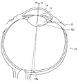
- FIG. 1 is an explanatory view showing the structure of an eyeball.
- the information processing apparatus is an apparatus that performs calibration that is performed to improve the gaze detection accuracy when detecting the gaze of the user with respect to the display.
- the information processing apparatus detects the line of sight of the user using, for example, pupil corneal reflex method.
- the pupil corneal reflex method is a method of irradiating the light from the light source to the eyeball of the user, and detecting the reflected light of the light on the corneal surface and the position of the pupil to estimate the gaze direction.
- the line of sight of the user is located on the visual axis A S connecting the nodes 12a and fovea 16a in the center rear of the lens 12 of the eye 10.
- the gaze direction estimated by the above-mentioned pupil corneal reflex method is on the optical axis AO on the normal line of the cornea 14 passing the center of the pupil 17.
- parameters are usually acquired at a plurality of (for example, 5 to 9) fixation points in the field of view.
- the information processing apparatus performs calibration so as to suppress the above-described variation in error.
- the information processing apparatus determines whether or not the calibration is possible for each of the eyes, and performs calibration on the eye using only the line-of-sight data related to the eye determined to be calibration possible. , Is one of the features.
- FIG. 2 is a diagram for explaining an outline of the present embodiment.
- FIG. 2 shows a situation in which the left eye LE of the user functions normally and the right eye RE does not function normally.
- the situation corresponds to, for example, a case where the right eye RE of the user is an artificial eye or a case where a symptom of strabismus is observed in the right eye RE.
- the information processing apparatus determines whether or not the calibration is possible for each of the left eye LE and the right eye RE, and uses only line-of-sight data related to the left eye LE determined to be calibration possible. Perform calibration only for the left eye LE. Further, the information processing apparatus according to the present embodiment can perform line-of-sight detection using only line-of-sight data related to the left eye LE for which calibration has been performed. In the example shown in FIG. 2, the information processing apparatus acquires only the line-of-sight data related to the left eye LE which has performed the calibration, and detects the line of sight of the user with respect to the points P1 to P3.
- the information processing apparatus According to the above-described function of the information processing apparatus according to the present embodiment, even when one of the eyes is not functioning properly, it is possible to detect the line of sight of the user. Further, according to the information processing apparatus according to the present embodiment, it is possible to perform more accurate line-of-sight detection by excluding the influence of the eye that may cause the accuracy decrease.
- FIG. 3 is an explanatory view showing the configuration of the display device 100 on the side facing the user's eyes.
- FIG. 4 is a schematic side view showing the positional relationship between the eyeball 10 of the user and the display device 100 when the display device 100 is mounted.
- the display device 100 is a device worn by the user on the head and used with the eye and the display unit facing each other.
- the display device 100 may be, for example, a non-transmissive, video transmissive, optical transmissive, or other head mounted display.
- display units 102R and 102L are provided at positions corresponding to the right eye and the left eye, respectively, on the side of the display device 100 according to the present embodiment facing the user's eyes.
- the display portions 102R and 102L according to the present embodiment are formed in a substantially rectangular shape.
- a concave portion 101a in which the user's nose is located may be formed between the display portions 102R and 102L.
- each light source 103Ra, 103Rb, 103Rc, and 103Rd are provided substantially at the centers of the four sides of the display unit 102R.
- four light sources 103La, 103Lb, 103Lc, and 103Ld are provided around the display unit 102L substantially at the centers of the four sides of the display unit 102L.
- These light sources 103Ra to 103Rd and 103La to 103Ld are light sources emitting infrared light.
- Each of the light sources 103Ra to 103Rd and 103La to 103Ld emits light to the eyeball 10 of the user facing the display units 102R and 102L in which the light sources 103Ra to 103Rd and 103La to 103Ld are provided.
- imaging units 104R and 104L for imaging the eyeball 10 are provided around the display units 102R and 102L, respectively.
- the imaging units 104R and 104L are provided, for example, below the display units 102R and 102L (below the light sources 103Rc and 103Lc provided below the display units 102R and 102L), as shown in FIG. .
- the imaging units 104R and 104L are arranged such that at least the pupil 17 of the eye 10 to be imaged is included in the imaging range, as shown in FIG.
- the imaging units 104R and 104L are arranged to have a predetermined elevation angle ⁇ .
- the elevation angle ⁇ may be, for example, about 30 °.
- the display device 100 is configured such that the display portions 102R and 102L are separated from the user's eye 10 by a predetermined distance when the display device 100 is worn by the user.
- the user wearing the display device 100 can fit the display areas of the display units 102R and 102L within the field of view without discomfort.
- the distance between the display portions 102R and 102L and the eye 10 of the user may be determined so that the display device 100 can be worn over the user.
- the imaging units 104R and 104L are arranged such that the pupil 17 of the eye 10 of the user is included in the imaging range in this state.
- FIG. 5 is a functional block diagram showing functional configurations of the display device 100 and the information processing device 200.
- the display device 100 includes a light source 110, an imaging unit 120, a display unit 130, a control unit 140, and a transmission / reception unit 150.
- the light source 110 emits light to the eyeball 10 of the user wearing the display device 100.
- the light source 110 is, for example, a light source that emits infrared light, and corresponds to the light sources 103Ra to 103Rd and 103La to 103Ld in FIG.
- the light source 110 emits light based on an instruction of the control unit 140.
- the imaging unit 120 captures an image of the eye 10 of the user wearing the display device 100.
- the imaging unit 120 corresponds to the imaging units 104R and 104L in FIG.
- the imaging unit 120 performs imaging based on an instruction of the control unit 140, and outputs the captured image to the control unit 140.
- the display unit 130 is an output unit that displays information.
- the display unit 130 corresponds to the display units 102R and 102L of FIG.
- the display unit 130 may be, for example, a liquid crystal display, an organic EL display, or a lens on which information is displayed by a projection device.
- the display unit 130 performs various information displays based on control by a display control unit 260 of the information processing apparatus 200 described later.
- the control unit 140 controls the overall functions of the display device 100.
- the control unit 140 performs, for example, lighting control of the light source 110 and imaging control of the imaging unit 120.
- the control unit 140 controls transmission and reception of information with the information processing apparatus 200 via the transmission and reception unit 150.
- the transmitting and receiving unit 150 is an interface that transmits and receives information to and from an external device.
- the display device 100 performs calibration by transmitting and receiving information to and from the information processing device 200.
- the display device 100 transmits the captured image captured by the imaging unit 120 to the information processing device 200 via the transmission / reception unit 150.
- the information processing apparatus 200 includes a transmission / reception unit 210, a marker control unit 220, an arithmetic processing unit 230, a storage unit 240, an evaluation unit 250, and a display control unit 260.
- the transmission and reception unit 210 is an interface that transmits and receives information to and from an external device.
- the transmission and reception unit 210 transmits and receives, with the display device 100, information for performing calibration.
- the transmission / reception unit 210 transmits, to the display device 100, lighting control information of the light source 110 at the time of calibration, imaging control information for causing the imaging unit 120 to perform imaging, display information to be displayed on the display unit 130, and the like.
- the transmission and reception unit 210 transmits the display control signal generated by the display control unit 260 to the display device 100.
- the transmission / reception unit 210 also receives a captured image or the like captured by the imaging unit 120 from the display device 100.
- the marker control unit 220 performs display control of a fixation point marker displayed on the display unit 130 of the display device 100 at the time of calibration.
- the fixation point marker is an object displayed in the display area to measure the deviation between the optical axis of the user and the visual axis.
- the marker control unit 220 sequentially displays the gaze point marker at a predetermined position (hereinafter, also referred to as a “calibration point”) so that the gaze data of the user is obtained at a plurality of positions in the display area.
- the marker control unit 220 repeats the process of moving the fixation point marker to the next calibration point when a predetermined number of line-of-sight data is acquired at the calibration point at which the fixation point marker is displayed, for all calibrations.
- the marker control unit 220 moves the gaze point marker between calibration points while displaying the gaze point marker.
- the user moves the line of sight so as to follow the fixation point marker, which eliminates the time for searching for the fixation point marker displayed at the calibration point as compared with the case where the fixation point marker is displayed intermittently.
- the movement of the line of sight directed to the fixation point marker can also be stabilized.
- the marker control unit 220 may control the moving speed of the gaze point marker moving between the calibration points.
- the marker control unit 220 may control the moving speed of the gaze point marker moving between the calibration points to be slower as it approaches the calibration point of the movement destination. As a result, the gaze point marker moves quickly immediately after the start of movement, but the movement becomes slower as it approaches the calibration point of the movement destination.
- the arithmetic processing unit 230 calculates the optical axis and the marker vector of the user when the gaze point marker is displayed at each calibration point.
- the arithmetic processing unit 230 acquires, from the display device 100, a photographed image obtained by photographing the eye of the user gazing at the gaze point marker in a state where light is emitted from the light source to the eyeball of the user. Calculate the marker vector.
- the calculated optical axis and marker vector are stored in the storage unit 240 for each calibration point.
- the arithmetic processing unit 230 determines whether or not the calibration is possible for each of the eyes based on the line-of-sight data, and performs calibration on the eye using only the line-of-sight data related to the eye determined to be calibration possible. It is one of the features.
- the storage unit 240 stores various types of information necessary for calibration of the display device 100.
- the storage unit 240 may, for example, move information specifying the position of the calibration point at which the gaze point marker is displayed and how to move the gaze point marker, the number of line-of-sight data acquired at each calibration point, and calibration Setting information such as a threshold value used for end determination is stored.
- the storage unit 240 stores the line-of-sight data calculated by the calculation processing unit 230.
- the evaluation unit 250 evaluates the variation of the optical axis of the user estimated at each calibration point.
- the arithmetic processing unit 230 determines, for example, whether or not the calibration is possible by determining whether the above-mentioned variation is within the allowable range. Details of the determination process will be described later.
- the display control unit 260 controls the display position of the object to be displayed on the display unit 130 according to the eye on which the calibration has been performed. At this time, the display control unit 260 causes the object to be displayed in the area corresponding to the eye on which the calibration has been performed. Details of display control by the display control unit 260 will be described later.
- FIG. 5 illustrates the information processing device 200 that performs the calibration process separately from the display device 100
- the present disclosure is not limited to such an example.
- some or all of the functions of the information processing device 200 illustrated in FIG. 5 may be realized as the functions of the display device 100.
- the calibration process of the display apparatus 100 by the information processing apparatus 200 according to the present embodiment is started by displaying the gaze point marker on the display unit 130 and directing the user's gaze to the gaze point marker.
- Display control of the gaze point marker is performed by the control unit 140 in response to an instruction from the marker control unit 220 of the information processing device 200.
- eye gaze data of the user is acquired at a plurality of positions in the display area of the display unit 130.
- the fixation point markers are sequentially displayed at a plurality of calibration points set in advance in the display area 300 of the display unit 130.
- FIG. 6 is an explanatory view showing one display example of the gaze point marker moved and displayed.
- the fixation point marker M is first displayed at a calibration point CP1 at the center of the display area 300.
- the fixation point marker M is displayed at the calibration point CP1
- the user directs the gaze to the fixation point marker M.
- the user's line of sight can be fixed to the calibration point CP1, and the line of sight data is acquired in this state.
- the gaze point marker M is moved to the calibration point CP2 at the upper left of the display area 300, which is the acquisition position of the next line-of-sight data. Then, the sight line data at the calibration point CP2 is acquired. Thereafter, acquisition and movement of the line-of-sight data are repeated at calibration point CP3 at the upper right of display area 300, calibration point CP4 at the lower left of display area 300, and calibration point CP5 at the lower right of display area 300.
- eye gaze data of the user at the calibration point is acquired.
- the gaze data includes an optical axis vector representing the estimated gaze direction of the user, and a marker vector from the user's pupil center to the gaze point marker. Also, line-of-sight data is acquired for the left eye and the right eye, respectively.
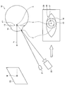
- the arithmetic processing unit 230 estimates the optical axis vector using, for example, the pupil corneal reflection method.
- the pupil corneal reflex method light is emitted from the light source 21 to the eyeball 10 of the user who observes the display surface 23 of the display unit, and the imaging unit 22 photographs the eyeball 10 irradiated with the light. Then, the optical axis is estimated based on the captured image 30 captured by the imaging unit 22.
- the case where the eyeball 10 is irradiated by one light source 21 will be described.
- FIG. 7 it is assumed that the user is gazing at the gaze point marker M displayed on the display surface 23. At this time, light is emitted to the eyeball 10 by the light source 21, and the eyeball 10 is photographed by the imaging unit 22. As shown in FIG. 7, the cornea 14, the iris 13, and the pupil 17 of the eyeball 10 of the user are photographed in the acquired photographed image 30 of the eyeball 10. Further, in the photographed image 30, a Purkinje Image P, which is a bright spot of the irradiation light emitted from the light source 21 to the eyeball 10, is photographed.
- calculation processing of the optical axis is performed.
- the calculation process of the optical axis is performed by the arithmetic processing unit 230. For this reason, first, the pupil center S and the Purkinje image P are detected from the photographed image 30. These detection processes can be performed by known image recognition techniques.
- various image processes for example, adjustment process of distortion, black level, white balance, etc.
- processing of acquiring the luminance distribution in the captured image 30 are performed.
- processing for detecting the contour (edge) of the image of the pupil 17 based on the acquired luminance distribution processing for approximating the contour of the detected image of the pupil 17 with a figure such as a circle or an ellipse, etc. It is also good.
- the pupil center S can be obtained from the detected image of the pupil 17.
- various image processing on the captured image 30, processing for acquiring the luminance distribution in the captured image 30, and the difference in luminance value with the surrounding pixels are relatively based on the luminance distribution.
- a series of processes such as a process of detecting a large pixel may be performed.
- the center of the Purkinje image P may be detected from the detected Purkinje image P.
- the curvature center point C of the cornea 14 is the center of the sphere when the cornea 14 is regarded as a part of the sphere.
- the three-dimensional coordinates of the pupil center S are calculated based on the image of the pupil 17 detected from the photographed image 30. Specifically, based on the positional relationship between the imaging unit 22 and the eye 10, refraction of light on the surface of the cornea 14, the distance between the curvature center point C of the cornea 14 and the pupil center S, etc., an image of the pupil 17 in the photographed image 30 Three-dimensional coordinates of each point on the contour of are calculated. The central point of these coordinates is taken as the three-dimensional coordinates of the pupil center S.
- the curvature center point C of the cornea 14 is calculated based on the Purkinje image P detected from the photographed image 30 and the center thereof. Specifically, based on the positional relationship between the light source 21, the imaging unit 22, and the eye 10, the radius of curvature of the cornea 14, etc., the eye from the surface of the cornea 14 on the straight line connecting the imaging unit 22 and the center of the Purkinje image P. A position advanced by the radius of curvature of the cornea 14 toward the inside of 10 is calculated as three-dimensional coordinates of the curvature center point C of the cornea 14.
- a straight line connecting the curvature center point C of the cornea 14 calculated in this manner and the pupil center S is an estimated optical axis. That is, the coordinates of the position where the optical axis intersects the display surface 23 is the estimated eye gaze position of the user.
- a vector from the curvature center point C of the cornea 14 toward the pupil center S is taken as an optical axis vector vo.
- the marker vector from the user's pupil center S to the gaze point marker M is the position on the display surface 23 at which the gaze point marker M is currently displayed from the pupil center S identified from the captured image 30 as described above. It can be calculated as a vector heading for
- the arithmetic processing unit 230 acquires optical axis vectors and marker vectors associated with the left eye and the right eye as eye gaze data by arithmetic operation.
- the line-of-sight data related to the left eye and the right eye acquired by the arithmetic processing unit 230 is stored in the storage unit 240.
- the arithmetic processing unit 230 determines whether the calculated optical axis vector vo is information available as a detection result of calibration.
- the arithmetic processing unit 230 determines whether or not the shake of the light axis vector vo is within a predetermined range, and the calculated light axis vector vo is largely deviated from the light axis vector vo thus obtained. It may be confirmed that it is not
- the light axis vector vo calculated by the calculation processing unit 230 is stored in the storage unit 240 as a history. Using this, the arithmetic processing unit 230 can, for example, determine that the angle between the average vo_ave of the light axis vector acquired in the past N times including the current calculation and the current light axis vector vo is within a predetermined value. Check.
- the optical axis vector vo calculated this time is not used as the detection result of the calibration because the blurring is large. Let's do it. Thereby, the accuracy of the optical axis vector can be enhanced.
- the average vo_ave of the light axis vector may be calculated using, for example, the past three light axis vectors vo. Further, the threshold value for determining the angle formed by the average vo_ave of the optical axis vector and the current optical axis vector vo may be, for example, about 3 °. Also, even when the optical axis vector vo is calculated from the captured image captured when the user is not looking at the fixation point marker M, the calculated optical axis vector vo deviates significantly from the average vo_ave of the optical axis vector It becomes a thing. Such a thing can also be excluded from a detection result by the said determination.
- the arithmetic processing unit 230 may also determine, for example, whether or not the angle ⁇ formed by the calculated marker vector vm and the optical axis vector vo is equal to or less than a predetermined value. By this determination, it can be confirmed whether the estimated optical axis vector vo is largely deviated from the actual gaze direction.
- the threshold value used here is determined in consideration of the deviation between the optical axis and the visual axis, the detection error of the optical axis, and the like.
- the estimated gaze direction of the user does not necessarily coincide with the direction in which the user is actually looking (ie, the gaze axis). This is due to the shape and size of the eyeball, the arrangement of the retina and the optic nerve in the eyeball, and the like.
- the optical axis and the visual axis are usually shifted by 4 to 8 °.
- a detection error of the optical axis is present by several degrees, for example, ⁇ 3 degrees. If other accumulated errors ⁇ 1 ° are added to these errors, it is assumed that an error of about 0 to 12 ° will occur. In this case, if the calculated angle ⁇ between the marker vector and the optical axis vector is in the range of 0 to 12 °, the accuracy of the calculated optical axis vector vo is considered to be acceptable and used as the detection result of calibration. You may
- the arithmetic processing unit 230 may perform an erroneous detection determination process so as not to use such an erroneous detection result as a calibration detection result. For example, when the calculated sizes of the left and right pupils are extremely different, there is a high possibility that the wrong place is recognized as a pupil. The gaze data acquired in such a case is not used as a detection result.
- a predetermined value for example, 1.2
- the sizes of the left and right pupils are extremely different, and the acquired sight line data is detected as a detection result You may not use it.
- the arithmetic processing unit 230 determines whether or not a predetermined number or more of gaze data that can be used at the calibration point at which the gaze point marker M is currently displayed is acquired.
- the arithmetic processing unit 230 stores the calibration point in the storage unit 240 as an available calibration point.
- the arithmetic processing unit 230 executes the above determination process on the left eye and the right eye, respectively.
- the arithmetic processing unit 230 determines whether or not line-of-sight data has been acquired for all calibration points, and if there is a calibration point for which line-of-sight data has not been acquired, the marker control unit 220 , And instructs to move the fixation point marker M to the next calibration point.
- the marker control unit 220 outputs an instruction to move the gaze point marker M to the next calibration point set in advance to the display device 100 via the transmission / reception unit 210.
- the fixation point marker M is displayed to direct the user's gaze.
- display control of the gaze point marker M is performed so that the gaze data of the user can be correctly acquired in a short time.
- the gaze point marker M moves between the calibration points in the displayed state.
- the user moves the line of sight so as to follow the fixation point marker, so it is not necessary to search for the fixation point marker M displayed at the calibration point as compared with the case where the fixation point marker M is displayed intermittently.
- the movement of the line of sight directed to the fixation point marker can be stabilized.
- the moving speed of the gaze point marker M moving between the calibration points is changed.
- the marker control unit 220 controls the moving speed of the gaze point marker M moving between the calibration points to be slower as it approaches the calibration point of the movement destination.
- calibration points for acquiring line-of-sight data in the display area 300 are usually displayed with a tendency that the shift between the visual axis and the optical axis tends to be large at the center of the display area 300 which is a position viewed when the user faces the front. It is set near the periphery of the area 300.
- the calibration points are usually set at a plurality of points (for example, 5 to 9) in the field of view. By performing calibration at these positions, correction processing can be performed such that the entire display region 300 looks uniform. Specifically, calibration may be performed at the center and at the four corners of the rectangular display area 300. Alternatively, calibration may be performed in the center of the rectangular display area 300 and in the vicinity of the center of each side.
- the moving order of the fixation point marker M may be determined so that the movement distance becomes as large as possible.
- the user moves the line of sight with the movement of the fixation point marker M, but when the movement distance of the fixation point marker M is short, it is difficult to align the line of sight with the fixation point marker M displayed at the next calibration point.
- the deviation from the optical axis becomes large.
- the gaze point marker M is moved in the horizontal direction of the display area 300, the shift between the visual axis and the optical axis is likely to be large.
- the marker M may be moved.
- the central calibration point CP1 is displayed and then the four calibration points CP2 to CP5 are jagged. You may move it to When line-of-sight data is acquired at the five calibration points CP1 to CP5 set at the center and around the center of each side, for example, calibration points CP1 to CP4 near the center of each side are Display in order as you draw. Thereafter, the central calibration point CP1 may be displayed.
- the arithmetic processing unit 230 determines whether or not to calibrate each of the left eye and the right eye. At this time, the arithmetic processing unit 230 may determine whether the left eye and the right eye are to be calibrated based on the available calibration points. More specifically, the arithmetic processing unit 230 can determine that the corresponding eye can not be calibrated based on the number of available calibration points falling below a threshold. If there are not three or more available calibration points, the arithmetic processing unit 230 may determine that the corresponding eye can not be calibrated.
- the evaluation unit 250 evaluates the variation of the optical axis vector vo.
- the arithmetic processing unit 230 can determine whether the calibration is possible or not on the basis of the variation of the optical axis vector evaluated by the evaluating unit 250 for each of the eyes.
- the optical axis vector vo at each calibration point has a value corresponding to the display position of the calibration point in the display area 300 when correctly estimated.
- FIG. 8 is a graph showing an example of the evaluation result of the variation of the optical axis.
- FIG. 8 shows the relationship between the angle ⁇ in the vertical direction of the light axis vector vo and the angle ⁇ in the horizontal direction of the light axis vector vo.
- the optical axis vector vo is defined based on the coordinate axes shown in FIG. FIG.
- FIG. 9 is an explanatory view showing coordinates of a marker vector and an optical axis vector.
- the x-axis represents the horizontal direction of the display area 300
- the y-axis represents the vertical direction of the display area 300
- the z-axis represents the depth direction of the display area 300.
- the angle ⁇ is the angle between the optical axis vector vo and the zx plane
- the angle ⁇ is the angle between the optical axis vector vo and the xy plane.
- the upper part of FIG. 8 shows the distribution of the optical axis vector vo when the calibration is correctly performed
- the lower part of FIG. 8 shows the distribution of the optical axis vector vo when the calibration is not correctly performed. ing.
- the optical axis vector vo is divided finely and distributed corresponding to the positions of the calibration points set at the center and the four corners of the display area 300.
- angles ⁇ in the vertical direction of the optical axis vector vo corresponding to the upper right, upper left and center calibration points of the display area 300 are substantially the same. It does not distribute well. Such a distribution is particularly likely to occur for wearers of hard contact lenses and for users with thin eyes and fine eyes.
- the evaluation unit 250 calculates the correlation coefficient between the marker vector vm and the optical axis vector vo as an evaluation value for evaluating the variation of the optical axis vector vo as a whole.
- the correlation coefficient r xy between the marker vector vm and the optical axis vector vo can be obtained, for example, by the following equation (1).
- i in the above equation (1) is a number assigned to each calibration point, and takes a value of 1 to n. If five calibration points are set, n is five. Also, x i and y i are x and y coordinates of the optical axis vector vo, and x ⁇ and y ⁇ are x and y coordinates of the marker vector vm. Note that x ⁇ and y ⁇ are attached to ⁇ on x and y.
- the difference between the angle ⁇ in the vertical direction and the angle ⁇ in the horizontal direction between the marker vector vm and the optical axis vector vo at all calibration points is evaluated.
- the correlation coefficient r xy calculated by the equation (1) becomes small.
- the arithmetic processing unit 230 can determine that the corresponding eye can not be calibrated based on the fact that the correlation coefficient r xy falls below the threshold.
- the arithmetic processing unit 230 determines whether or not calibration is possible for each of the left eye and the right eye based on the number of available calibration points and the variation of the optical axis vector. be able to. Further, the arithmetic processing unit 230 can perform calibration on the eye using only the sight line data of the eye determined to be calibration-enabled. According to the above-described function of the arithmetic processing unit 230 according to the present embodiment, it is possible to eliminate the influence of the eye that may be a cause of the reduction in accuracy, and to realize gaze detection with high accuracy.
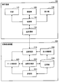
- FIG. 10 is a flowchart showing a flow of calibration processing by the information processing apparatus 200 according to the present embodiment.
- the information processing apparatus 200 performs availability determination for each calibration point (S1101).
- the flow of the availability determination for each calibration point in step S1101 will be separately described in detail.
- the information processing apparatus 200 determines whether or not calibration is possible for each of the left eye and the right eye (S1102).
- the information processing apparatus 200 first determines whether the number of available calibration points is equal to or greater than a threshold (S1103).
- the information processing apparatus 200 determines that the corresponding eye can not be calibrated (S1105).
- the information processing apparatus 200 subsequently determines whether the variation of the estimated optical axis vector is equal to or less than the threshold (S1103). S1104). More specifically, the information processing device 200 can perform the above determination based on the correlation coefficient r xy between the marker vector vm and the optical axis vector vo.
- the information processing apparatus 200 determines that the corresponding eye can not be calibrated (S1105).
- the information processing apparatus 200 determines that the corresponding eye can be calibrated (S1106).
- the information processing apparatus 200 subsequently determines whether there is one or more eyes that can be calibrated (S1107).
- the information processing apparatus 200 executes a calibration process on the eyes that can be calibrated (S1108).
- the information processing apparatus 200 may return to step S1101 and repeatedly execute the availability determination for each calibration point.
- FIG. 11 is a flow chart showing the flow of availability determination for each calibration point according to the present embodiment.
- the information processing apparatus 200 determines availability of calibration points for each of the left eye and the right eye (S 1201).
- the information processing apparatus 200 first displays a gaze point marker on the calibration point (S1202).
- the information processing apparatus 200 acquires line-of-sight data based on the captured image including the user's eye captured when the fixation point marker is displayed at the calibration point (S1203).
- the gaze data described above includes information related to the optical axis vector and the marker vector.
- the information processing apparatus 200 determines whether the blur of the optical axis vector is within a predetermined range, based on the line-of-sight data acquired in step S1203 (S1204).
- the information processing apparatus 200 returns to step S1202.
- the information processing apparatus 200 subsequently determines whether the difference between the optical axis vector and the marker vector is within the predetermined range. It is determined (S1205).
- the information processing apparatus 200 returns to step S1202.
- the information processing device 200 accumulates the gaze data acquired in step S1203 as usable gaze data (S1206) .
- the information processing apparatus 200 determines whether or not the stored line-of-sight data is present in a predetermined number or more (S1207).
- the information processing apparatus 200 determines that the corresponding calibration point is available (S1208).
- the information processing device 200 determines whether a predetermined time set in advance has passed (S1209)
- the information processing apparatus 200 determines that the corresponding calibration point is not available (S1210).
- the information processing apparatus 200 returns to step S1202.
- the information processing apparatus 200 repeatedly acquires line-of-sight data until a predetermined number or more of line-of-sight data are accumulated or a predetermined time elapses.
- said predetermined time may be changed dynamically. For example, if there is a calibration execution record before, it is assumed that this is an area in which line-of-sight data can be originally acquired, so a longer time may be set.
- step S1208 or S1209 the information processing apparatus 200 determines whether the determination of availability for all calibration points is completed (S1211).
- the information processing apparatus 200 moves the gaze point marker to the next calibration (S1212), and returns to step S1201. Do.
- the information processing apparatus 200 ends the determination of availability of calibration points and shifts to the process of step S1102 in FIG.
- FIG. 12 is an explanatory diagram for describing changing of the calibration point position.
- the first calibration point is set in the display area 300 based on an area obtained by reducing the display area 300 by a predetermined ratio ⁇ .
- the default value of the position of the calibration point is, for example, the four corners of the center of the display area 300 and the area of 90% of the display area.
- the information processing apparatus 200 may change the position of the calibration point to the center of the display area 300 in the above-described repetitive processing.
- the information processing apparatus 200 can set, for example, the positions of the calibration points at the four corners at the four corners of the area of 80% of the display area. By thus shifting the position of the calibration point to the center of the display area, the user can easily view the gaze point marker, and can easily acquire correct line-of-sight data.
- the flow of the calibration process by the information processing apparatus 200 according to the present embodiment has been described above in detail. As described above, according to the information processing apparatus 200 according to the present embodiment, even when one of the eyes is not functioning properly, calibration is performed on the eye predicted to be functioning properly. To detect the line of sight of the eye. Further, according to the information processing apparatus 200 according to the present embodiment, it is possible to realize more accurate gaze detection by eliminating the influence of the eye that may cause the accuracy reduction among the both eyes.
- the information processing apparatus 200 changes the calibration point when the predetermined number of visual line data is accumulated has been described, but the flow of processing by the information processing apparatus 200 according to the present embodiment Is not limited to such an example.
- the information processing apparatus 200 can also repeat the process of changing the calibration point a predetermined number of times, for example, each time point of sight data is accumulated.
- the information processing apparatus 200 can perform various controls in addition to the main control described above.
- the information processing apparatus 200 can also improve the overall accuracy by using a calibration point different from that in the past calibration.
- the information processing apparatus 200 may shorten the time required for calibration by using a part of the past calibration results.
- the information processing apparatus 200 does not determine whether the calibration for the eye is possible or not. It is also good.
- the information processing apparatus 200 may present to the user which eye is to be used for line-of-sight detection according to the result of calibration. Further, the information processing apparatus 200 may present an alert or the like to the user when it is determined that an eye having a calibration result in the past can not perform calibration.
- the information processing device 200 performs control such that the background is difficult to visually recognize in accordance with the brightness of the surroundings at the time of calibration and the like. Control such as displaying a fixation point marker in a color that does not assimilate to the background may be performed.
- the information processing apparatus 200 can also reduce power consumption effectively by performing control to turn off the light source 110 and the imaging unit 120 associated with an eye that is not used for eye gaze detection.
- the functions of the information processing apparatus 200 according to the present embodiment can be flexibly deformed in accordance with the specifications and the operation.
- the display control unit 260 of the information processing device 200 can control the display position of the object to be displayed on the display unit 130 of the display device 100 based on the calibration execution result.
- the display control unit 260 can improve the detection accuracy of the sight line with respect to the object by displaying the object in the area corresponding to the eye on which the calibration is performed in the display region 300. It is possible.
- FIG. 13 is a diagram illustrating an example of display control of an object by the display control unit 260 according to the present embodiment.
- FIG. 13 shows a field of view FV to which the display unit 130 corresponds.
- the field of view FV consists of a left field of view LFV corresponding to the left eye and a right field of view RFV corresponding to the right eye.
- the display control unit 260 displays the object Ob in the area corresponding to the left eye for which the calibration was performed. You may display it.
- the display control unit 260 can cause the object Ob to be displayed by bringing it closer to the left field of view LFV corresponding to the left eye.
- the display control unit 260 can further improve the line-of-sight detection accuracy of the object Ob by displaying the object Ob in the calibration area LCA in the left visual field LFV.
- the above-mentioned calibration area LCA is an area determined based on the calibration point used when performing calibration on the left eye.
- the calibration area LCA corresponds to the rectangular area defined by the calibration points CP2 to CP5.
- the display control unit 260 can effectively improve the line-of-sight detection accuracy related to the object Ob by displaying the object Ob in the area used for calibration.
- the display control unit 260 is not limited to the example shown in FIG. 13 and may perform various display controls.
- FIG. 14 is a diagram illustrating an example of display control of an object when calibration is performed in both the left eye and the right eye. Note that FIG. 14 shows an example in which the calibration area LCA related to the left eye and the calibration area RCA related to the right eye have different areas. At this time, the display control unit 260 may display the object Ob in an area where the calibration areas LCA and RCA overlap, as illustrated.
- the display control unit 260 according to the present embodiment can appropriately and flexibly control the display position of the object Ob in accordance with the calibration execution result and the characteristics of the display device 100, the application, and the like.
- the information processing apparatus 200 determines whether or not calibration is performed for each of the eyes, and the method for performing calibration based on the determination is mainly described. Said to.
- an imaging unit capable of imaging infrared light and a light source for emitting the infrared light are disposed in the display device 100. Is required. At this time, it is desirable to dispose the light source near the center of the field of view of the user from the viewpoint of the accuracy of gaze detection.
- the light source inhibits the display of visual information by the display unit. Further, in the above arrangement, the light source enters the user's field of view, which causes a bad effect that the user's viewing experience is significantly impaired.
- the light source be disposed at a position as inconspicuous as possible in the field of view of the user from the viewpoint of the viewing experience, unlike the viewpoint of the accuracy of gaze detection.
- display devices corresponding to AR technology and VR (Virtual Reality) technology are required to have a wide viewing angle, it is general that physical constraints exist in the arrangement of light sources.
- downsizing of the light source is expected to reduce the appearance, but there is a limit to miniaturizing the light source and there is a concern that the cost may increase.
- the technical idea according to the second embodiment of the present disclosure is conceived on the basis of the above-described point, and makes it possible to realize high-accuracy gaze detection without disturbing the user's viewing experience.
- a transparent member having at least two light emitting points for irradiating the light guided by the light source to the eye of the user is used.
- features of the transparent member according to the present embodiment will be described in detail. In the following description, differences from the first embodiment will be mainly described, and detailed description of the functional configurations common to the first embodiment will be omitted.
- the display device 100 and the information processing device 200 are realized as an integral device will be described as an example.
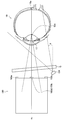
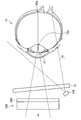
- FIG. 15 is a schematic side view showing the positional relationship between the user's eye 10 and the information processing device 200 when the information processing device 200 is worn by the user.
- the information processing apparatus 200 according to the present embodiment further includes a transparent member 105 in addition to the configuration described in the first embodiment.
- the transparent member 105 is disposed on the side of the eye 10 of the user in the information processing apparatus 200.
- the transparent member 105 is formed, for example, using a transparent material such as glass or acrylic resin. Therefore, the user can visually recognize various visual information displayed on the display unit (not shown) of the information processing apparatus 200 through the transparent member 105.
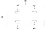
- FIG. 16 is a front view showing the transparent member 105 according to the present embodiment from the user side.
- the transparent member 105 according to the present embodiment may be formed, for example, in a plate shape.
- the transparent member 105 according to the present embodiment is characterized by having a plurality of light emitting points ep for emitting the light guided from the light source to the eyes of the user.
- the transparent member 105 In order to secure the accuracy of gaze detection by pupil corneal reflex method, it is desirable that at least two bright spots be detected on the cornea, and the detection accuracy tends to improve as the number of bright spots detected increases. is there. Therefore, the transparent member 105 according to the present embodiment has at least two light emitting points ep, and the two light emitting points ep are disposed at positions where two bright points can be formed on the cornea in each of the eyes. May be done.
- FIG. 16 shows an example in which the transparent member 105 has four light emitting points ep1 to ep4. Further, as shown in FIG. 15, the imaging unit 104 according to the present embodiment is disposed at a position at which at least two bright spots on the cornea can be imaged.
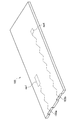
- FIG. 17 is a perspective view showing the structural features of the transparent member 105 according to the present embodiment.
- the light emitting point ep according to the present embodiment plays a role of irradiating the light guided from the light source to the eyes of the user.
- the light emitting point ep realizes light guiding by reflecting the light emitted from the light source 103 disposed on the side of the transparent member 105 inside the transparent member 105.
- FIG. 17 shows an example in which the light emitting point ep1 guides light from the light source 103a and the light emitting point ep4 guides light from the light source 103b.
- the light emission point ep as described above may be formed, for example, by notch processing. According to the notch processing, it is possible to form a light emitting point of any shape at any place on the transparent member 105 at low cost. As described above, it is desirable that more bright spots be detected on the cornea in order to secure the accuracy of gaze detection by the pupil corneal reflection method. However, in the conventional method, one light source generally forms one bright spot, and in the case of detecting many bright spots on the cornea, it is necessary to physically increase the number of light sources. there were.
- the present embodiment by overlapping the plurality of transparent members 105 and controlling the light emission intensity of the light source 103, it is also possible to switch the irradiation of the light by the plurality of light emitting points ep. It is possible to use different bright spots for each user.
- the light emitting point ep according to the present embodiment may be formed by a method other than notch processing.
- the light emitting point ep can also be formed, for example, by changing the reflectance of an arbitrary place with the surroundings.
- a method of changing the reflectance for example, it is assumed that a material different from the surrounding is used for forming the light emitting point ep, or a separate member is added to forming the light emitting point ep.
- the plurality of light emitting points ep1 and ep4 can be formed to have different light emission shapes, that is, by making the shapes of the bright points different, bright points Separation can easily be realized.
- the light emitting point ep according to the present embodiment may be formed in a linear shape or a mesh shape.
- FIG. 18 is a view showing a linear light emitting point epL according to the present embodiment
- FIG. 19 is a view showing a mesh shaped light emitting point epM according to the present embodiment.
- the transparent member 105 according to the present embodiment can be formed integrally with the display unit, for example. For this reason, according to the transparent member 105 according to the present embodiment, the information processing apparatus 200 can be further reduced in size and weight.
- FIG. 20 is a view for explaining a rod-shaped transparent member according to the present embodiment.
- FIG. 20 shows the field of view FV of the user and two rod-shaped transparent members 105 a and 105 b.
- the two rod-shaped transparent members 105a and 105b can respectively emit light guided from the light sources 103a and 103b disposed outside the field of view FV to the user's eyes.
- the transparent member 105 and the light emitting point ep according to the present embodiment have been described above in detail. According to the transparent member 105 and the light emitting point ep according to the present embodiment, it is possible to emit light guided from the light source 103 disposed outside the field of view of the user from any place such as near the center of the field of view.
- the light emitting point ep according to the present embodiment can be formed into an arbitrary shape, and by forming the light emitting point ep of various shapes according to the application, the accuracy of the sight line detection can be obtained. It can be improved effectively.
- the light emitting point ep according to the present embodiment can be formed in a large amount and stably by a press or the like, so that the manufacturing cost can be reduced and higher positional accuracy can be expected compared to the attachment of the light source.
- the transparent member 105 according to the present embodiment may be used in combination with direct irradiation from the light source 103.
- the information processing apparatus 200 can also perform various controls related to the light emitting point ep and the light source 103. For example, in a dark environment, the information processing apparatus 200 may perform control such as reducing power consumption by reducing the emission intensity of the light source 103 or limiting the number of emission points ep to be used. .
- the configuration and functions of the information processing apparatus 200 according to the present embodiment can be flexibly deformed according to the specification and operation.
- the transparent member 105 which concerns on this embodiment is applicable also to the information processing apparatus which does not perform the arithmetic processing in embodiment of this indication. That is, the transparent member 105 may be considered not to be a component dependent on arithmetic processing in the embodiment of the present disclosure.
- the transparent member 105 according to the present embodiment the visual axis detection with higher accuracy is provided as compared with the general hardware configuration, and as a result, at least a part of the general hardware configuration issues can be obtained. Note that it can be solved.
- FIG. 21 is a block diagram showing an example of the hardware configuration of the information processing apparatus 200 according to an embodiment of the present disclosure.
- the information processing apparatus 200 includes, for example, a CPU 871, a ROM 872, a RAM 873, a host bus 874, a bridge 875, an external bus 876, an interface 877, an input device 878, and an output device 879.
- Storage 880, drive 881, connection port 882, and communication device 883 Note that the hardware configuration shown here is an example, and some of the components may be omitted. In addition, components other than the components shown here may be further included.
- the CPU 871 functions as, for example, an arithmetic processing unit or a control unit, and controls the overall operation or a part of each component based on various programs recorded in the ROM 872, the RAM 873, the storage 880, or the removable recording medium 901.
- the ROM 872 is a means for storing a program read by the CPU 871, data used for an operation, and the like.
- the RAM 873 temporarily or permanently stores, for example, a program read by the CPU 871 and various parameters appropriately changed when the program is executed.
- the CPU 871, the ROM 872, and the RAM 873 are mutually connected via, for example, a host bus 874 capable of high-speed data transmission.
- host bus 874 is connected to external bus 876, which has a relatively low data transmission speed, via bridge 875, for example.
- the external bus 876 is connected to various components via an interface 877.
- Input device 8708 For the input device 878, for example, a mouse, a keyboard, a touch panel, a button, a switch, a lever, and the like are used. Furthermore, as the input device 878, a remote controller (hereinafter, remote control) capable of transmitting a control signal using infrared rays or other radio waves may be used.
- the input device 878 also includes a voice input device such as a microphone.
- the output device 879 is a display device such as a CRT (Cathode Ray Tube), an LCD, or an organic EL, a speaker, an audio output device such as a headphone, a printer, a mobile phone, or a facsimile. It is a device that can be notified visually or aurally. Also, the output device 879 according to the present disclosure includes various vibration devices capable of outputting haptic stimulation.
- the storage 880 is a device for storing various data.
- a magnetic storage device such as a hard disk drive (HDD), a semiconductor storage device, an optical storage device, a magneto-optical storage device, or the like is used.
- the drive 881 is a device that reads information recorded on a removable recording medium 901 such as a magnetic disk, an optical disk, a magneto-optical disk, or a semiconductor memory, or writes information on the removable recording medium 901, for example.
- a removable recording medium 901 such as a magnetic disk, an optical disk, a magneto-optical disk, or a semiconductor memory
- the removable recording medium 901 is, for example, DVD media, Blu-ray (registered trademark) media, HD DVD media, various semiconductor storage media, and the like.
- the removable recording medium 901 may be, for example, an IC card equipped with a non-contact IC chip, an electronic device, or the like.
- connection port 882 is, for example, a port for connecting an externally connected device 902 such as a USB (Universal Serial Bus) port, an IEEE 1394 port, a SCSI (Small Computer System Interface), an RS-232C port, or an optical audio terminal. is there.
- an externally connected device 902 such as a USB (Universal Serial Bus) port, an IEEE 1394 port, a SCSI (Small Computer System Interface), an RS-232C port, or an optical audio terminal. is there.
- the external connection device 902 is, for example, a printer, a portable music player, a digital camera, a digital video camera, an IC recorder, or the like.
- the communication device 883 is a communication device for connecting to a network.
- a communication card for wired or wireless LAN Bluetooth (registered trademark) or WUSB (Wireless USB), a router for optical communication, ADSL (Asymmetric Digital) (Subscriber Line) router, or modem for various communications.
- Bluetooth registered trademark
- WUSB Wireless USB
- ADSL Asymmetric Digital
- Subscriber Line Subscriber Line
- the information processing apparatus 200 determines whether or not the calibration is possible for each of the eyes, and uses only the line-of-sight data of the eye determined to be calibration enabled for the eye Calibration can be performed. According to such a configuration, it is possible to perform more accurate line-of-sight detection by eliminating the influence of the eye that may cause the accuracy reduction among the two eyes.
- each step related to the processing of the information processing apparatus 200 in the present specification does not necessarily have to be processed chronologically in the order described in the flowchart.
- each step relating to the processing of the information processing apparatus 200 may be processed in an order different from the order described in the flowchart or may be processed in parallel.
- An arithmetic processing unit that executes arithmetic processing related to calibration of gaze detection for the display unit; Equipped with The arithmetic processing unit determines whether or not calibration is performed for each of the eyes based on the acquired line-of-sight data, and performs calibration on the eye using only the line-of-sight data of the eye determined to be calibration-enabled. , Information processing device.
- the arithmetic processing unit determines whether the calibration is possible or not based on available calibration points for each of the eyes. The information processing apparatus according to (1).
- the arithmetic processing unit determines that the corresponding eye can not be calibrated based on the number of available calibration points falling below a threshold.
- the information processing apparatus determines whether the calibration is possible or not on the basis of variations in optical axis vectors at all available calibration points for each of the eyes.
- the information processing apparatus according to any one of the above (1) to (3).
- the arithmetic processing unit is configured to calculate a correlation coefficient between the optical axis vector and a marker vector from the user's pupil center to the calibration point at which the gaze point marker is displayed based on the correlation coefficient falling below a threshold. Determine that the corresponding eye is not calibrated, The information processing apparatus according to (4).
- the arithmetic processing unit determines availability of the calibration point based on the line-of-sight data accumulated at the calibration point.
- the information processing apparatus according to any one of the above (2) to (5).
- the arithmetic processing unit determines that the calibration point is not available based on the fact that the number of line-of-sight data accumulated at the calibration point does not exceed the predetermined number within a predetermined time.
- the information processing apparatus according to any one of the above (2) to (6).
- the arithmetic processing unit performs pupil corneal reflex method based on a captured image including the user's eye captured when the user's eye is irradiated with light from the light source and the fixation point marker is displayed at the calibration point. , Calculate the optical axis vector, The information processing apparatus according to any one of the above (1) to (7).
- a display control unit that controls a display position of an object to be displayed on the display unit according to the eye on which the calibration has been performed; Further comprising The information processing apparatus according to any one of the above (1) to (8).
- the display control unit displays the object in an area corresponding to the eye on which the calibration has been performed.
- the display control unit displays the object in a calibration area related to the eye for which the calibration has been performed.
- (12) An evaluation unit that evaluates variations in optical axis vectors calculated for a plurality of calibration points; Further comprising The information processing apparatus according to any one of the above (1) to (11).
- a marker control unit that changes the display position of the gaze point marker displayed by the display unit; Further comprising The information processing apparatus according to any one of the above (1) to (12).
- a transparent member having at least two light emitting points for emitting light guided from a light source to the user's eyes, And further The at least two light emitting points are arranged at positions that can form at least two bright spots on the cornea in each of the two eyes.
- the transparent member is formed in a plate shape, and is disposed between the user's eyes and the display unit.
- the light emitting point is formed by notch processing.
- At least two of the light emitting points have different light emitting shapes from one another
- the information processing apparatus according to any one of the above (14) to (16).
- An imaging unit configured to capture an image including the eyeball of the user; And further The imaging unit is disposed at a position at which at least two of the bright spots on the cornea can be imaged.
- the information processing apparatus according to any one of the above (14) to (17).
- the processor performing arithmetic processing related to calibration of gaze detection for the display unit; Including Executing the arithmetic processing determines whether or not calibration is performed for each of the eyes based on the acquired line-of-sight data, and calibration is performed on the eye using only the line-of-sight data of the eye determined to be calibration-enabled.
- Information processing method () Computer, An arithmetic processing unit that executes arithmetic processing related to calibration of gaze detection for the display unit; Equipped with The arithmetic processing unit determines whether or not calibration is performed for each of the eyes based on the acquired line-of-sight data, and performs calibration on the eye using only the line-of-sight data of the eye determined to be calibration-enabled.
- Information processing device Program to function as. (21)
- a transparent member having at least two light emitting points for emitting light guided from a light source to the user's eyes, Equipped with The at least two light emitting points are arranged at positions that can form at least two bright spots on the cornea in each of the two eyes. Display device for gaze detection.
- At least two light emitting points for irradiating the user's eyes with light guided from a light source Have The at least two light emitting points are arranged at positions that can form at least two bright spots on the cornea in each of the two eyes. Transparent member for gaze detection.
Abstract
Description
1.第1の実施形態
1.1.概要
1.2.表示装置のハードウェア構成
1.3.機能構成
1.4.キャリブレーション処理
1.5.キャリブレーション処理の流れ
1.6.キャリブレーションの実行結果に基づく表示制御
2.第2の実施形態
2.1.概要
2.2.透明部材の特徴
3.ハードウェア構成例
4.まとめ The description will be made in the following order.
1. First Embodiment 1.1. Overview 1.2. Hardware configuration of display device 1.3. Functional configuration 1.4. Calibration process 1.5. Flow of calibration process 1.6. Display control based on
<<1.1.概要>>
まず、本開示の第1の実施形態に係る情報処理装置の概要について説明する。図1は、眼球の構造を示す説明図である。 <1. First embodiment>
<< 1.1. Overview >>
First, an overview of an information processing apparatus according to a first embodiment of the present disclosure will be described. FIG. 1 is an explanatory view showing the structure of an eyeball.
(手順1)視野内のある点(以下、「注視点」ともいう。)を見たときの光軸を推定
(手順2)角膜曲率中心から注視点への注視点ベクトルと推定された光軸のベクトルとの差分を測定
(手順3)(手順2)で測定した差分に基づき、任意の点を見たときの光軸より、そのときの視軸を推定 Calibration is performed in the following procedure.
(Procedure 1) Estimate the optical axis when looking at a certain point in the field of view (hereinafter, also referred to as "gaze point") (Procedure 2) An optical axis estimated to be a gaze point vector from the corneal curvature center to the gaze point Measure the difference with the vector of (Step 3) (Step 2) and estimate the visual axis at that time from the optical axis when looking at any point based on the difference measured in (Step 2)
本実施形態に係る情報処理装置の説明に先立ち、図3および図4を参照して、本実施形態に係る情報処理装置によるキャリブレーションが行われる表示装置100のハードウェア構成を説明する。なお、図3は、表示装置100の、ユーザの眼と対向する側の構成を示す説明図である。図4は、表示装置100が装着されたときの、ユーザの眼球10と表示装置100との位置関係を示す概略側面図である。 << 1.2. Display hardware configuration >>
Prior to the description of the information processing apparatus according to the present embodiment, the hardware configuration of the
次に、図5に基づいて、上述した表示装置100と、表示装置100のキャリブレーションを行う情報処理装置200との機能構成を説明する。なお、図5は、表示装置100および情報処理装置200の機能構成を示す機能ブロック図である。 << 1.3. Functional configuration >>
Next, based on FIG. 5, the functional configuration of the
表示装置100は、図5に示すように、光源110と、撮像部120と、表示部130と、制御部140と、送受信部150とを備える。 (Display device 100)
As shown in FIG. 5, the
情報処理装置200は、図5に示すように、送受信部210と、マーカ制御部220と、演算処理部230と、記憶部240と、評価部250と、表示制御部260とを備える。 (Information processing apparatus 200)
As shown in FIG. 5, the
次に、図6~図10を参照して、本実施形態に係る情報処理装置200による表示装置100のキャリブレーション処理について説明する。本実施形態に係る情報処理装置200による表示装置100のキャリブレーション処理は、表示部130に注視点マーカを表示し、ユーザの視線を注視点マーカに向けさせることから開始される。注視点マーカの表示制御は、情報処理装置200のマーカ制御部220の指示を受けて、制御部140により行われる。キャリブレーションでは、表示部130の表示領域内の複数位置においてユーザの視線データを取得する。視線データを取得する位置であるキャリブレーション点に注視点マーカを表示させることで、ユーザに意図的に視線を注視点マーカに向けさせ、視線データを取得することが可能となる。 << 1.4. Calibration process >>
Next, calibration processing of the
演算処理部230は、例えば、瞳孔角膜反射法を用いて光軸ベクトルを推定する。ここで、図7を参照して、瞳孔角膜反射法を用いた光軸の推定処理について説明する。図7は、瞳孔角膜反射法を用いた光軸ベクトルの算出処理について説明するための説明図である。瞳孔角膜反射法では、表示部の表示面23を観察するユーザの眼球10に対して光源21から光を照射し、撮像部22により光が照射された眼球10を撮影する。そして、撮像部22により撮影された撮影画像30に基づき、光軸が推定される。ここでは説明を簡単にするため、1つの光源21により眼球10を照射した場合を説明する。 (Calculation of light axis vector)
The
一方、ユーザの瞳孔中心Sから注視点マーカMへのマーカベクトルは、上述のように撮影画像30から特定された瞳孔中心Sから、現在注視点マーカMが表示されている表示面23上の位置に向かうベクトルとして算出することができる。 (Calculation of marker vector)
On the other hand, the marker vector from the user's pupil center S to the gaze point marker M is the position on the
ここで、演算処理部230は、演算した光軸ベクトルvoがキャリブレーションの検出結果として利用可能な情報であるか否かを判定する。 (Suppression of variation in detection results)
Here, the
さらに、上述した検出結果のばらつきを抑制するための判定をクリアした場合であっても、瞳孔や輝点が誤った場所を検出し続けることもある。誤った検出結果を用いると、正しくキャリブレーション処理を行うことができない。そこで、演算処理部230は、このような誤った検出結果をキャリブレーションの検出結果として用いないようにする誤検出判定処理を行ってもよい。例えば、演算された左右の瞳孔の大きさが極端に異なる場合には、瞳孔として誤った場所を認識している可能性が高い。このような場合に取得された視線データは検出結果として用いないようにする。具体的には、例えば左右の瞳孔のサイズ比が所定の値(例えば1.2)を超えた場合には、左右の瞳孔の大きさが極端に異なるとして、取得された視線データは検出結果として用いないようにしてもよい。 (False detection judgment)
Furthermore, even when the determination for suppressing the variation in the detection result described above is cleared, the pupil or the bright spot may continue to detect the wrong place. If an incorrect detection result is used, calibration processing can not be performed correctly. Therefore, the
注視点マーカMは、ユーザの視線を向けさせるために表示させるものである。ここで、ユーザの視線データを短時間で正しく取得できるように、注視点マーカMの表示制御が行われる。 (Movement process of gaze point marker)
The fixation point marker M is displayed to direct the user's gaze. Here, display control of the gaze point marker M is performed so that the gaze data of the user can be correctly acquired in a short time.
すべてのキャリブレーション点において視線データが取得されると、演算処理部230は、左眼および右眼のそれぞれに関しキャリブレーション可否を判定する。この際、演算処理部230は、利用可能なキャリブレーション点に基づいて、左眼および右眼に関するキャリブレーション可否を判定してよい。より詳細には、演算処理部230は、利用可能なキャリブレーション点の数が閾値を下回ることに基づいて、対応する眼がキャリブレーション不能であると判定することができる。演算処理部230は、利用可能なキャリブレーション点が3点以上ない場合には、該当する眼がキャリブレーション不能であると判定してもよい。 (Determination of calibration availability)
When line-of-sight data is acquired at all calibration points, the
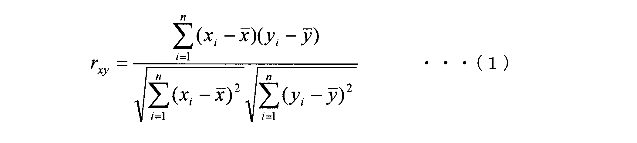
次に、本実施形態に係る情報処理装置200によるキャリブレーション処理の流れに着目して詳細に説明する。図10は、本実施形態に係る情報処理装置200によるキャリブレーション処理の流れを示すフローチャートである。 << 1.5. Flow of calibration process >>
Next, the flow of the calibration process performed by the
次に、本実施形態に係るキャリブレーションの実行結果に基づく表示制御について説明する。本実施形態に係る情報処理装置200の表示制御部260は、キャリブレーションの実行結果に基づいて表示装置100の表示部130に表示させるオブジェクトの表示位置を制御することができる。 << 1.6. Display control based on calibration execution results >>
Next, display control based on the execution result of calibration according to the present embodiment will be described. The
<<2.1.概要>>
次に、本開示の第2の実施形態について説明する。上記における第1の実施形態の説明では、視線検出に係るキャリブレーションにおいて、情報処理装置200が両眼のそれぞれに関しキャリブレーション可否を判定し、当該判定に基づくキャリブレーションを実行する際の手法について中心に述べた。 <2. Second embodiment>
<< 2.1. Overview >>
Next, a second embodiment of the present disclosure will be described. In the above description of the first embodiment, in calibration related to gaze detection, the
図15は、ユーザにより情報処理装置200が装着された際の、ユーザの眼球10と情報処理装置200との位置関係を示す概略側面図である。図15に示すように、本実施形態に係る情報処理装置200は、第1の実施形態において説明した構成に加え、透明部材105をさらに備える。また、透明部材105は、情報処理装置200においてユーザの眼球10側に配置される。 << 2.2. Characteristics of transparent members >>
FIG. 15 is a schematic side view showing the positional relationship between the user's
次に、本開示の一実施形態に係る情報処理装置200のハードウェア構成例について説明する。図21は、本開示の一実施形態に係る情報処理装置200のハードウェア構成例を示すブロック図である。図21を参照すると、情報処理装置200は、例えば、CPU871と、ROM872と、RAM873と、ホストバス874と、ブリッジ875と、外部バス876と、インターフェース877と、入力装置878と、出力装置879と、ストレージ880と、ドライブ881と、接続ポート882と、通信装置883と、を有する。なお、ここで示すハードウェア構成は一例であり、構成要素の一部が省略されてもよい。また、ここで示される構成要素以外の構成要素をさらに含んでもよい。 <3. Hardware configuration example>
Next, a hardware configuration example of the
CPU871は、例えば、演算処理装置又は制御装置として機能し、ROM872、RAM873、ストレージ880、又はリムーバブル記録媒体901に記録された各種プログラムに基づいて各構成要素の動作全般又はその一部を制御する。 (CPU 871)
The
ROM872は、CPU871に読み込まれるプログラムや演算に用いるデータ等を格納する手段である。RAM873には、例えば、CPU871に読み込まれるプログラムや、そのプログラムを実行する際に適宜変化する各種パラメータ等が一時的又は永続的に格納される。 (
The
CPU871、ROM872、RAM873は、例えば、高速なデータ伝送が可能なホストバス874を介して相互に接続される。一方、ホストバス874は、例えば、ブリッジ875を介して比較的データ伝送速度が低速な外部バス876に接続される。また、外部バス876は、インターフェース877を介して種々の構成要素と接続される。 (
The
入力装置878には、例えば、マウス、キーボード、タッチパネル、ボタン、スイッチ、及びレバー等が用いられる。さらに、入力装置878としては、赤外線やその他の電波を利用して制御信号を送信することが可能なリモートコントローラ(以下、リモコン)が用いられることもある。また、入力装置878には、マイクロフォンなどの音声入力装置が含まれる。 (Input device 878)
For the
出力装置879は、例えば、CRT(Cathode Ray Tube)、LCD、又は有機EL等のディスプレイ装置、スピーカ、ヘッドホン等のオーディオ出力装置、プリンタ、携帯電話、又はファクシミリ等、取得した情報を利用者に対して視覚的又は聴覚的に通知することが可能な装置である。また、本開示に係る出力装置879は、触覚刺激を出力することが可能な種々の振動デバイスを含む。 (Output device 879)
The
ストレージ880は、各種のデータを格納するための装置である。ストレージ880としては、例えば、ハードディスクドライブ(HDD)等の磁気記憶デバイス、半導体記憶デバイス、光記憶デバイス、又は光磁気記憶デバイス等が用いられる。 (Storage 880)
The
ドライブ881は、例えば、磁気ディスク、光ディスク、光磁気ディスク、又は半導体メモリ等のリムーバブル記録媒体901に記録された情報を読み出し、又はリムーバブル記録媒体901に情報を書き込む装置である。 (Drive 881)
The
リムーバブル記録媒体901は、例えば、DVDメディア、Blu-ray(登録商標)メディア、HD DVDメディア、各種の半導体記憶メディア等である。もちろん、リムーバブル記録媒体901は、例えば、非接触型ICチップを搭載したICカード、又は電子機器等であってもよい。 (Removable recording medium 901)
The
接続ポート882は、例えば、USB(Universal Serial Bus)ポート、IEEE1394ポート、SCSI(Small Computer System Interface)、RS-232Cポート、又は光オーディオ端子等のような外部接続機器902を接続するためのポートである。 (Connection port 882)
The
外部接続機器902は、例えば、プリンタ、携帯音楽プレーヤ、デジタルカメラ、デジタルビデオカメラ、又はICレコーダ等である。 (Externally connected device 902)
The
通信装置883は、ネットワークに接続するための通信デバイスであり、例えば、有線又は無線LAN、Bluetooth(登録商標)、又はWUSB(Wireless USB)用の通信カード、光通信用のルータ、ADSL(Asymmetric Digital Subscriber Line)用のルータ、又は各種通信用のモデム等である。 (Communication device 883)
The
以上説明したように、本開示の一実施形態に係る情報処理装置200は、両眼のそれぞれに関しキャリブレーション可否を判定し、キャリブレーション可能と判定した眼に係る視線データのみを用いて当該眼に対するキャリブレーションを実行することができる。係る構成によれば、両眼のうち精度低下の原因となり得る眼の影響を排除することでより精度の高い視線検出を行うことが可能となる。 <4. Summary>
As described above, the
(1)
表示部に対する視線検出のキャリブレーションに係る演算処理を実行する演算処理部、
を備え、
前記演算処理部は、取得された視線データに基づいて両眼のそれぞれに関しキャリブレーション可否を判定し、キャリブレーション可能と判定した眼に係る前記視線データのみを用いて当該眼に対するキャリブレーションを実行する、
情報処理装置。
(2)
前記演算処理部は、両眼のそれぞれに関し、利用可能なキャリブレーション点に基づいて前記キャリブレーション可否を判定する、
前記(1)に記載の情報処理装置。
(3)
前記演算処理部は、利用可能な前記キャリブレーション点の数が閾値を下回ることに基づいて、対応する眼がキャリブレーション不能であると判定する、
前記(2)に記載の情報処理装置。
(4)
前記演算処理部は、両眼のそれぞれに関し、利用可能なすべてのキャリブレーション点における光軸ベクトルのばらつきに基づいて、前記キャリブレーション可否を判定する、
前記(1)~(3)のいずれかに記載の情報処理装置。
(5)
前記演算処理部は、前記光軸ベクトルとユーザの瞳孔中心から注視点マーカが表示されている前記キャリブレーション点へのマーカベクトルとの相関関係を表す相関係数が閾値を下回ることに基づいて、対応する眼がキャリブレーション不能であると判定する、
前記(4)に記載の情報処理装置。
(6)
前記演算処理部は、前記キャリブレーション点において蓄積された前記視線データに基づいて、当該キャリブレーション点の利用可否を判定する、
前記(2)~(5)のいずれかに記載の情報処理装置。
(7)
前記演算処理部は、前記キャリブレーション点において蓄積された視線データの数が所定時間内に所定数を上回らないことに基づいて、当該キャリブレーション点が利用不能であると判定する、
前記(2)~(6)のいずれかに記載の情報処理装置。
(8)
前記演算処理部は、ユーザの眼に光源から光が照射され、キャリブレーション点に注視点マーカが表示されているときに撮影されたユーザの眼を含む撮影画像に基づいて、瞳孔角膜反射法により、光軸ベクトルを演算する、
前記(1)~(7)のいずれかに記載の情報処理装置。
(9)
前記キャリブレーションが実行された眼に応じて、前記表示部に表示させるオブジェクトの表示位置を制御する表示制御部、
をさらに備える、
前記(1)~(8)のいずれかに記載の情報処理装置。
(10)
前記表示制御部は、前記キャリブレーションが実行された眼に対応するエリアに前記オブジェクトを表示させる、
前記(9)に記載の情報処理装置。
(11)
前記表示制御部は、前記キャリブレーションが実行された眼に係るキャリブレーションエリアに前記オブジェクトを表示させる、
前記(10)に記載の情報処理装置。
(12)
複数のキャリブレーション点について演算された光軸ベクトルのばらつきを評価する評価部、
をさらに備える、
前記(1)~(11)のいずれかに記載の情報処理装置。
(13)
前記表示部により表示される注視点マーカの表示位置を変化させるマーカ制御部、
をさらに備える、
前記(1)~(12)のいずれかに記載の情報処理装置。
(14)
光源から導光した光をユーザの眼に照射する少なくとも2つの発光点を有する透明部材、
をさらに備え、
少なくとも2つの前記発光点は、両眼のそれぞれにおける角膜上に少なくとも2つの輝点を形成可能な位置に配置される、
前記(1)~(13)のいずれかに記載の情報処理装置。
(15)
前記透明部材は、板状に形成され、ユーザの両眼と前記表示部との間に配置される、
前記(14)に記載の情報処理装置。
(16)
前記発光点は、切り欠き加工により形成される、
前記(14)または(15)に記載の情報処理装置。
(17)
少なくとも2つの前記発光点は、互いに異なる発光形状を有する、
前記(14)~(16)のいずれかに記載の情報処理装置。
(18)
ユーザの眼球を含む画像を撮像する撮像部、
をさらに備え、
前記撮像部は、角膜上における少なくとも2つの前記輝点を撮像可能な位置に配置される、
前記(14)~(17)のいずれかに記載の情報処理装置。
(19)
プロセッサが、表示部に対する視線検出のキャリブレーションに係る演算処理を実行すること、
を含み、
前記演算処理を実行することは、取得された視線データに基づいて両眼のそれぞれに関しキャリブレーション可否を判定し、キャリブレーション可能と判定した眼に係る前記視線データのみを用いて当該眼に対するキャリブレーションを実行すること、
さらに含む、
情報処理方法。
(20)
コンピュータを、
表示部に対する視線検出のキャリブレーションに係る演算処理を実行する演算処理部、
を備え、
前記演算処理部は、取得された視線データに基づいて両眼のそれぞれに関しキャリブレーション可否を判定し、キャリブレーション可能と判定した眼に係る前記視線データのみを用いて当該眼に対するキャリブレーションを実行する、
情報処理装置、
として機能させるためのプログラム。
(21)
光源から導光した光をユーザの眼に照射する少なくとも2つの発光点を有する透明部材、
を備え、
少なくとも2つの前記発光点は、両眼のそれぞれにおける角膜上に少なくとも2つの輝点を形成可能な位置に配置される、
視線検出用の表示装置。
(22)
光源から導光した光をユーザの眼に照射する少なくとも2つの発光点、
を有し、
少なくとも2つの前記発光点は、両眼のそれぞれにおける角膜上に少なくとも2つの輝点を形成可能な位置に配置される、
視線検出用の透明部材。 The following configurations are also within the technical scope of the present disclosure.
(1)
An arithmetic processing unit that executes arithmetic processing related to calibration of gaze detection for the display unit;
Equipped with
The arithmetic processing unit determines whether or not calibration is performed for each of the eyes based on the acquired line-of-sight data, and performs calibration on the eye using only the line-of-sight data of the eye determined to be calibration-enabled. ,
Information processing device.
(2)
The arithmetic processing unit determines whether the calibration is possible or not based on available calibration points for each of the eyes.
The information processing apparatus according to (1).
(3)
The arithmetic processing unit determines that the corresponding eye can not be calibrated based on the number of available calibration points falling below a threshold.
The information processing apparatus according to (2).
(4)
The arithmetic processing unit determines whether the calibration is possible or not on the basis of variations in optical axis vectors at all available calibration points for each of the eyes.
The information processing apparatus according to any one of the above (1) to (3).
(5)
The arithmetic processing unit is configured to calculate a correlation coefficient between the optical axis vector and a marker vector from the user's pupil center to the calibration point at which the gaze point marker is displayed based on the correlation coefficient falling below a threshold. Determine that the corresponding eye is not calibrated,
The information processing apparatus according to (4).
(6)
The arithmetic processing unit determines availability of the calibration point based on the line-of-sight data accumulated at the calibration point.
The information processing apparatus according to any one of the above (2) to (5).
(7)
The arithmetic processing unit determines that the calibration point is not available based on the fact that the number of line-of-sight data accumulated at the calibration point does not exceed the predetermined number within a predetermined time.
The information processing apparatus according to any one of the above (2) to (6).
(8)
The arithmetic processing unit performs pupil corneal reflex method based on a captured image including the user's eye captured when the user's eye is irradiated with light from the light source and the fixation point marker is displayed at the calibration point. , Calculate the optical axis vector,
The information processing apparatus according to any one of the above (1) to (7).
(9)
A display control unit that controls a display position of an object to be displayed on the display unit according to the eye on which the calibration has been performed;
Further comprising
The information processing apparatus according to any one of the above (1) to (8).
(10)
The display control unit displays the object in an area corresponding to the eye on which the calibration has been performed.
The information processing apparatus according to (9).
(11)
The display control unit displays the object in a calibration area related to the eye for which the calibration has been performed.
The information processing apparatus according to (10).
(12)
An evaluation unit that evaluates variations in optical axis vectors calculated for a plurality of calibration points;
Further comprising
The information processing apparatus according to any one of the above (1) to (11).
(13)
A marker control unit that changes the display position of the gaze point marker displayed by the display unit;
Further comprising
The information processing apparatus according to any one of the above (1) to (12).
(14)
A transparent member having at least two light emitting points for emitting light guided from a light source to the user's eyes,
And further
The at least two light emitting points are arranged at positions that can form at least two bright spots on the cornea in each of the two eyes.
The information processing apparatus according to any one of the above (1) to (13).
(15)
The transparent member is formed in a plate shape, and is disposed between the user's eyes and the display unit.
The information processing apparatus according to (14).
(16)
The light emitting point is formed by notch processing.
The information processing apparatus according to (14) or (15).
(17)
At least two of the light emitting points have different light emitting shapes from one another
The information processing apparatus according to any one of the above (14) to (16).
(18)
An imaging unit configured to capture an image including the eyeball of the user;
And further
The imaging unit is disposed at a position at which at least two of the bright spots on the cornea can be imaged.
The information processing apparatus according to any one of the above (14) to (17).
(19)
The processor performing arithmetic processing related to calibration of gaze detection for the display unit;
Including
Executing the arithmetic processing determines whether or not calibration is performed for each of the eyes based on the acquired line-of-sight data, and calibration is performed on the eye using only the line-of-sight data of the eye determined to be calibration-enabled. To do,
In addition,
Information processing method.
(20)
Computer,
An arithmetic processing unit that executes arithmetic processing related to calibration of gaze detection for the display unit;
Equipped with
The arithmetic processing unit determines whether or not calibration is performed for each of the eyes based on the acquired line-of-sight data, and performs calibration on the eye using only the line-of-sight data of the eye determined to be calibration-enabled. ,
Information processing device,
Program to function as.
(21)
A transparent member having at least two light emitting points for emitting light guided from a light source to the user's eyes,
Equipped with
The at least two light emitting points are arranged at positions that can form at least two bright spots on the cornea in each of the two eyes.
Display device for gaze detection.
(22)
At least two light emitting points for irradiating the user's eyes with light guided from a light source
Have
The at least two light emitting points are arranged at positions that can form at least two bright spots on the cornea in each of the two eyes.
Transparent member for gaze detection.
14 角膜
17 瞳孔
100 表示装置
110 光源
120 撮像部
130 表示部
140 制御部
150 送受信部
200 情報処理装置
210 送受信部
220 マーカ制御部
230 演算処理部
240 記憶部
250 評価部
260 表示制御部
105 透明部材 DESCRIPTION OF
Claims (20)
- 表示部に対する視線検出のキャリブレーションに係る演算処理を実行する演算処理部、
を備え、
前記演算処理部は、取得された視線データに基づいて両眼のそれぞれに関しキャリブレーション可否を判定し、キャリブレーション可能と判定した眼に係る前記視線データのみを用いて当該眼に対するキャリブレーションを実行する、
情報処理装置。 An arithmetic processing unit that executes arithmetic processing related to calibration of gaze detection for the display unit;
Equipped with
The arithmetic processing unit determines whether or not calibration is performed for each of the eyes based on the acquired line-of-sight data, and performs calibration on the eye using only the line-of-sight data of the eye determined to be calibration-enabled. ,
Information processing device. - 前記演算処理部は、両眼のそれぞれに関し、利用可能なキャリブレーション点に基づいて前記キャリブレーション可否を判定する、
請求項1に記載の情報処理装置。 The arithmetic processing unit determines whether the calibration is possible or not based on available calibration points for each of the eyes.
An information processing apparatus according to claim 1. - 前記演算処理部は、利用可能な前記キャリブレーション点の数が閾値を下回ることに基づいて、対応する眼がキャリブレーション不能であると判定する、
請求項2に記載の情報処理装置。 The arithmetic processing unit determines that the corresponding eye can not be calibrated based on the number of available calibration points falling below a threshold.
The information processing apparatus according to claim 2. - 前記演算処理部は、両眼のそれぞれに関し、利用可能なすべてのキャリブレーション点における光軸ベクトルのばらつきに基づいて、前記キャリブレーション可否を判定する、
請求項1に記載の情報処理装置。 The arithmetic processing unit determines whether the calibration is possible or not on the basis of variations in optical axis vectors at all available calibration points for each of the eyes.
An information processing apparatus according to claim 1. - 前記演算処理部は、前記光軸ベクトルとユーザの瞳孔中心から注視点マーカが表示されている前記キャリブレーション点へのマーカベクトルとの相関関係を表す相関係数が閾値を下回ることに基づいて、対応する眼がキャリブレーション不能であると判定する、
請求項4に記載の情報処理装置。 The arithmetic processing unit is configured to calculate a correlation coefficient between the optical axis vector and a marker vector from the user's pupil center to the calibration point at which the gaze point marker is displayed based on the correlation coefficient falling below a threshold. Determine that the corresponding eye is not calibrated,
The information processing apparatus according to claim 4. - 前記演算処理部は、前記キャリブレーション点において蓄積された前記視線データに基づいて、当該キャリブレーション点の利用可否を判定する、
請求項2に記載の情報処理装置。 The arithmetic processing unit determines availability of the calibration point based on the line-of-sight data accumulated at the calibration point.
The information processing apparatus according to claim 2. - 前記演算処理部は、前記キャリブレーション点において蓄積された視線データの数が所定時間内に所定数を上回らないことに基づいて、当該キャリブレーション点が利用不能であると判定する、
請求項2に記載の情報処理装置。 The arithmetic processing unit determines that the calibration point is not available based on the fact that the number of line-of-sight data accumulated at the calibration point does not exceed the predetermined number within a predetermined time.
The information processing apparatus according to claim 2. - 前記演算処理部は、ユーザの眼に光源から光が照射され、キャリブレーション点に注視点マーカが表示されているときに撮影されたユーザの眼を含む撮影画像に基づいて、瞳孔角膜反射法により、光軸ベクトルを演算する、
請求項1に記載の情報処理装置。 The arithmetic processing unit performs pupil corneal reflex method based on a captured image including the user's eye captured when the user's eye is irradiated with light from the light source and the fixation point marker is displayed at the calibration point. , Calculate the optical axis vector,
An information processing apparatus according to claim 1. - 前記キャリブレーションが実行された眼に応じて、前記表示部に表示させるオブジェクトの表示位置を制御する表示制御部、
をさらに備える、
請求項1に記載の情報処理装置。 A display control unit that controls a display position of an object to be displayed on the display unit according to the eye on which the calibration has been performed;
Further comprising
An information processing apparatus according to claim 1. - 前記表示制御部は、前記キャリブレーションが実行された眼に対応するエリアに前記オブジェクトを表示させる、
請求項9に記載の情報処理装置。 The display control unit displays the object in an area corresponding to the eye on which the calibration has been performed.
The information processing apparatus according to claim 9. - 前記表示制御部は、前記キャリブレーションが実行された眼に係るキャリブレーションエリアに前記オブジェクトを表示させる、
請求項10に記載の情報処理装置。 The display control unit displays the object in a calibration area related to the eye for which the calibration has been performed.
The information processing apparatus according to claim 10. - 複数のキャリブレーション点について演算された光軸ベクトルのばらつきを評価する評価部、
をさらに備える、
請求項1に記載の情報処理装置。 An evaluation unit that evaluates variations in optical axis vectors calculated for a plurality of calibration points;
Further comprising
An information processing apparatus according to claim 1. - 前記表示部により表示される注視点マーカの表示位置を変化させるマーカ制御部、
をさらに備える、
請求項1に記載の情報処理装置。 A marker control unit that changes the display position of the gaze point marker displayed by the display unit;
Further comprising
An information processing apparatus according to claim 1. - 光源から導光した光をユーザの眼に照射する少なくとも2つの発光点を有する透明部材、
をさらに備え、
少なくとも2つの前記発光点は、両眼のそれぞれにおける角膜上に少なくとも2つの輝点を形成可能な位置に配置される、
請求項1に記載の情報処理装置。 A transparent member having at least two light emitting points for emitting light guided from a light source to the user's eyes,
And further
The at least two light emitting points are arranged at positions that can form at least two bright spots on the cornea in each of the two eyes.
An information processing apparatus according to claim 1. - 前記透明部材は、板状に形成され、ユーザの両眼と前記表示部との間に配置される、
請求項14に記載の情報処理装置。 The transparent member is formed in a plate shape, and is disposed between the user's eyes and the display unit.
The information processing apparatus according to claim 14. - 前記発光点は、切り欠き加工により形成される、
請求項14に記載の情報処理装置。 The light emitting point is formed by notch processing.
The information processing apparatus according to claim 14. - 少なくとも2つの前記発光点は、互いに異なる発光形状を有する、
請求項14に記載の情報処理装置。 At least two of the light emitting points have different light emitting shapes from one another
The information processing apparatus according to claim 14. - ユーザの眼球を含む画像を撮像する撮像部、
をさらに備え、
前記撮像部は、角膜上における少なくとも2つの前記輝点を撮像可能な位置に配置される、
請求項14に記載の情報処理装置。 An imaging unit configured to capture an image including the eyeball of the user;
And further
The imaging unit is disposed at a position at which at least two of the bright spots on the cornea can be imaged.
The information processing apparatus according to claim 14. - プロセッサが、表示部に対する視線検出のキャリブレーションに係る演算処理を実行すること、
を含み、
前記演算処理を実行することは、取得された視線データに基づいて両眼のそれぞれに関しキャリブレーション可否を判定し、キャリブレーション可能と判定した眼に係る前記視線データのみを用いて当該眼に対するキャリブレーションを実行すること、
さらに含む、
情報処理方法。 The processor performing arithmetic processing related to calibration of gaze detection for the display unit;
Including
Executing the arithmetic processing determines whether or not calibration is performed for each of the eyes based on the acquired line-of-sight data, and calibration is performed on the eye using only the line-of-sight data of the eye determined to be calibration-enabled. To do,
In addition,
Information processing method. - コンピュータを、
表示部に対する視線検出のキャリブレーションに係る演算処理を実行する演算処理部、
を備え、
前記演算処理部は、取得された視線データに基づいて両眼のそれぞれに関しキャリブレーション可否を判定し、キャリブレーション可能と判定した眼に係る前記視線データのみを用いて当該眼に対するキャリブレーションを実行する、
情報処理装置、
として機能させるためのプログラム。 Computer,
An arithmetic processing unit that executes arithmetic processing related to calibration of gaze detection for the display unit;
Equipped with
The arithmetic processing unit determines whether or not calibration is performed for each of the eyes based on the acquired line-of-sight data, and performs calibration on the eye using only the line-of-sight data of the eye determined to be calibration-enabled. ,
Information processing device,
Program to function as.
Priority Applications (4)
| Application Number | Priority Date | Filing Date | Title |
|---|---|---|---|
| EP18838854.0A EP3660636A4 (en) | 2017-07-27 | 2018-05-22 | Information processing device, information processing method, and program |
| JP2019532400A JP7081599B2 (en) | 2017-07-27 | 2018-05-22 | Information processing equipment, information processing methods, and programs |
| US16/631,901 US11490808B2 (en) | 2017-07-27 | 2018-05-22 | Information processing device and information processing method |
| KR1020207001259A KR20200035003A (en) | 2017-07-27 | 2018-05-22 | Information processing apparatus, information processing method, and program |
Applications Claiming Priority (2)
| Application Number | Priority Date | Filing Date | Title |
|---|---|---|---|
| JP2017145346 | 2017-07-27 | ||
| JP2017-145346 | 2017-07-27 |
Publications (1)
| Publication Number | Publication Date |
|---|---|
| WO2019021601A1 true WO2019021601A1 (en) | 2019-01-31 |
Family
ID=65039521
Family Applications (1)
| Application Number | Title | Priority Date | Filing Date |
|---|---|---|---|
| PCT/JP2018/019630 WO2019021601A1 (en) | 2017-07-27 | 2018-05-22 | Information processing device, information processing method, and program |
Country Status (5)
| Country | Link |
|---|---|
| US (1) | US11490808B2 (en) |
| EP (1) | EP3660636A4 (en) |
| JP (1) | JP7081599B2 (en) |
| KR (1) | KR20200035003A (en) |
| WO (1) | WO2019021601A1 (en) |
Cited By (2)
| Publication number | Priority date | Publication date | Assignee | Title |
|---|---|---|---|---|
| WO2021140938A1 (en) * | 2020-01-06 | 2021-07-15 | ソニーグループ株式会社 | Information processing device, information processing method, and computer-readable recording medium |
| US11794095B2 (en) | 2019-04-24 | 2023-10-24 | Sony Interactive Entertainment Inc. | Information processing apparatus and device information derivation method |
Families Citing this family (1)
| Publication number | Priority date | Publication date | Assignee | Title |
|---|---|---|---|---|
| JP2017211891A (en) * | 2016-05-27 | 2017-11-30 | ソニー株式会社 | Information processing device, information processing method, and recording medium |
Citations (6)
| Publication number | Priority date | Publication date | Assignee | Title |
|---|---|---|---|---|
| JP2006293909A (en) * | 2005-04-14 | 2006-10-26 | Denso Corp | Driver sight line direction detecting device |
| JP2007136000A (en) * | 2005-11-21 | 2007-06-07 | Nippon Telegr & Teleph Corp <Ntt> | Apparatus, method and program for measuring visual axis |
| JP2010259605A (en) * | 2009-05-01 | 2010-11-18 | Nippon Hoso Kyokai <Nhk> | Visual line measuring device and visual line measuring program |
| JP2016502120A (en) * | 2012-09-03 | 2016-01-21 | ゼンソモトリック インストゥルメンツ ゲゼルシャフト ヒューア イノベイティブ ゼンソリック エムベーハーSENSOMOTORIC INSTRUMENTS Gesellschaft fur innovative Sensorik mbH | Head mounted system and method for computing and rendering a stream of digital images using the head mounted system |
| JP2017037329A (en) * | 2012-09-19 | 2017-02-16 | 株式会社ニコン | Line-of-sight detection device, display method, spectacle lens design method, spectacle lens selection method, spectacle lens fabrication method, printed matter and spectacle lens sales method |
| JP2017102687A (en) * | 2015-12-01 | 2017-06-08 | 株式会社Jvcケンウッド | Visual line detection device and visual line detection method |
Family Cites Families (8)
| Publication number | Priority date | Publication date | Assignee | Title |
|---|---|---|---|---|
| JPH05333259A (en) | 1992-06-02 | 1993-12-17 | Canon Inc | Optical device provided with means for detecting line of sight |
| AU4219693A (en) * | 1992-09-30 | 1994-04-14 | Apple Computer, Inc. | Inter-task buffer and connections |
| KR20060030608A (en) * | 2004-10-06 | 2006-04-11 | 엘지전자 주식회사 | Recording mdium, method and apparatus for reproducing data from the recording medium |
| JP5927966B2 (en) * | 2012-02-14 | 2016-06-01 | ソニー株式会社 | Display control apparatus, display control method, and program |
| JP5958303B2 (en) * | 2012-11-27 | 2016-07-27 | 株式会社デンソー | Text-to-speech device |
| JP2014160982A (en) * | 2013-02-20 | 2014-09-04 | Sony Corp | Image processor, photography control method, and program |
| DE112016003719T5 (en) | 2015-08-15 | 2018-05-09 | Google LLC (n.d.Ges.d. Staates Delaware) | System and method for biomechanics-based eye signals for interaction with real and virtual objects |
| GB2563276B (en) * | 2017-06-09 | 2021-12-01 | Advanced Risc Mach Ltd | Virtual reality systems |
-
2018
- 2018-05-22 KR KR1020207001259A patent/KR20200035003A/en not_active Application Discontinuation
- 2018-05-22 JP JP2019532400A patent/JP7081599B2/en active Active
- 2018-05-22 EP EP18838854.0A patent/EP3660636A4/en not_active Ceased
- 2018-05-22 US US16/631,901 patent/US11490808B2/en active Active
- 2018-05-22 WO PCT/JP2018/019630 patent/WO2019021601A1/en active Application Filing
Patent Citations (6)
| Publication number | Priority date | Publication date | Assignee | Title |
|---|---|---|---|---|
| JP2006293909A (en) * | 2005-04-14 | 2006-10-26 | Denso Corp | Driver sight line direction detecting device |
| JP2007136000A (en) * | 2005-11-21 | 2007-06-07 | Nippon Telegr & Teleph Corp <Ntt> | Apparatus, method and program for measuring visual axis |
| JP2010259605A (en) * | 2009-05-01 | 2010-11-18 | Nippon Hoso Kyokai <Nhk> | Visual line measuring device and visual line measuring program |
| JP2016502120A (en) * | 2012-09-03 | 2016-01-21 | ゼンソモトリック インストゥルメンツ ゲゼルシャフト ヒューア イノベイティブ ゼンソリック エムベーハーSENSOMOTORIC INSTRUMENTS Gesellschaft fur innovative Sensorik mbH | Head mounted system and method for computing and rendering a stream of digital images using the head mounted system |
| JP2017037329A (en) * | 2012-09-19 | 2017-02-16 | 株式会社ニコン | Line-of-sight detection device, display method, spectacle lens design method, spectacle lens selection method, spectacle lens fabrication method, printed matter and spectacle lens sales method |
| JP2017102687A (en) * | 2015-12-01 | 2017-06-08 | 株式会社Jvcケンウッド | Visual line detection device and visual line detection method |
Non-Patent Citations (1)
| Title |
|---|
| See also references of EP3660636A4 * |
Cited By (2)
| Publication number | Priority date | Publication date | Assignee | Title |
|---|---|---|---|---|
| US11794095B2 (en) | 2019-04-24 | 2023-10-24 | Sony Interactive Entertainment Inc. | Information processing apparatus and device information derivation method |
| WO2021140938A1 (en) * | 2020-01-06 | 2021-07-15 | ソニーグループ株式会社 | Information processing device, information processing method, and computer-readable recording medium |
Also Published As
| Publication number | Publication date |
|---|---|
| JPWO2019021601A1 (en) | 2020-05-28 |
| EP3660636A4 (en) | 2020-07-08 |
| US20200154997A1 (en) | 2020-05-21 |
| KR20200035003A (en) | 2020-04-01 |
| JP7081599B2 (en) | 2022-06-07 |
| US11490808B2 (en) | 2022-11-08 |
| EP3660636A1 (en) | 2020-06-03 |
Similar Documents
| Publication | Publication Date | Title |
|---|---|---|
| KR102469507B1 (en) | Information processing apparatus, information processing method and program | |
| US10268290B2 (en) | Eye tracking using structured light | |
| US10048750B2 (en) | Content projection system and content projection method | |
| US10409368B2 (en) | Eye-gaze detection system, displacement detection method, and displacement detection program | |
| KR20140059213A (en) | Head mounted display with iris scan profiling | |
| US20160110600A1 (en) | Image collection and locating method, and image collection and locating device | |
| US11487354B2 (en) | Information processing apparatus, information processing method, and program | |
| WO2015035823A1 (en) | Image collection with increased accuracy | |
| US20150304625A1 (en) | Image processing device, method, and recording medium | |
| CN111830714B (en) | Image display control method, image display control device and head-mounted display device | |
| JP7081599B2 (en) | Information processing equipment, information processing methods, and programs | |
| US20210034151A1 (en) | Electronic device, control method, and non-transitory computer readable medium | |
| US20200213467A1 (en) | Image display system, image display method, and image display program | |
| US11443719B2 (en) | Information processing apparatus and information processing method | |
| KR101817436B1 (en) | Apparatus and method for displaying contents using electrooculogram sensors | |
| US11682368B1 (en) | Method of operating a mobile device | |
| US20220329740A1 (en) | Electronic apparatus, method for controlling electronic apparatus, and non-transitory computer readable storage medium | |
| WO2017081915A1 (en) | Image processing device, image processing method and program | |
| WO2019116675A1 (en) | Information processing device, information processing method, and program | |
| US11829530B2 (en) | Electronic device, control method of electronic device, and non-transitory computer readable medium | |
| US20230393655A1 (en) | Electronic apparatus | |
| US20240045498A1 (en) | Electronic apparatus | |
| US20230092593A1 (en) | Detection device detecting gaze point of user, control method therefor, and storage medium storing control program therefor | |
| JP2023006630A (en) | Detection device and control method therefor | |
| EP4222944A1 (en) | Image capture eyewear with automatic image sending to recipients determined based on context |
Legal Events
| Date | Code | Title | Description |
|---|---|---|---|
| 121 | Ep: the epo has been informed by wipo that ep was designated in this application |
Ref document number: 18838854 Country of ref document: EP Kind code of ref document: A1 |
|
| ENP | Entry into the national phase |
Ref document number: 2019532400 Country of ref document: JP Kind code of ref document: A |
|
| NENP | Non-entry into the national phase |
Ref country code: DE |
|
| WWE | Wipo information: entry into national phase |
Ref document number: 2018838854 Country of ref document: EP |
|
| ENP | Entry into the national phase |
Ref document number: 2018838854 Country of ref document: EP Effective date: 20200227 |