WO2019017017A1 - ウェアレベリング処理を行うメモリコントローラ - Google Patents
ウェアレベリング処理を行うメモリコントローラ Download PDFInfo
- Publication number
- WO2019017017A1 WO2019017017A1 PCT/JP2018/014241 JP2018014241W WO2019017017A1 WO 2019017017 A1 WO2019017017 A1 WO 2019017017A1 JP 2018014241 W JP2018014241 W JP 2018014241W WO 2019017017 A1 WO2019017017 A1 WO 2019017017A1
- Authority
- WO
- WIPO (PCT)
- Prior art keywords
- unit
- management unit
- section
- memory
- writing
- Prior art date
- Legal status (The legal status is an assumption and is not a legal conclusion. Google has not performed a legal analysis and makes no representation as to the accuracy of the status listed.)
- Ceased
Links
Images









Classifications
-
- G—PHYSICS
- G06—COMPUTING OR CALCULATING; COUNTING
- G06F—ELECTRIC DIGITAL DATA PROCESSING
- G06F3/00—Input arrangements for transferring data to be processed into a form capable of being handled by the computer; Output arrangements for transferring data from processing unit to output unit, e.g. interface arrangements
- G06F3/06—Digital input from, or digital output to, record carriers, e.g. RAID, emulated record carriers or networked record carriers
- G06F3/0601—Interfaces specially adapted for storage systems
- G06F3/0628—Interfaces specially adapted for storage systems making use of a particular technique
- G06F3/0655—Vertical data movement, i.e. input-output transfer; data movement between one or more hosts and one or more storage devices
-
- G—PHYSICS
- G06—COMPUTING OR CALCULATING; COUNTING
- G06F—ELECTRIC DIGITAL DATA PROCESSING
- G06F3/00—Input arrangements for transferring data to be processed into a form capable of being handled by the computer; Output arrangements for transferring data from processing unit to output unit, e.g. interface arrangements
- G06F3/06—Digital input from, or digital output to, record carriers, e.g. RAID, emulated record carriers or networked record carriers
- G06F3/0601—Interfaces specially adapted for storage systems
- G06F3/0602—Interfaces specially adapted for storage systems specifically adapted to achieve a particular effect
- G06F3/061—Improving I/O performance
-
- G—PHYSICS
- G06—COMPUTING OR CALCULATING; COUNTING
- G06F—ELECTRIC DIGITAL DATA PROCESSING
- G06F12/00—Accessing, addressing or allocating within memory systems or architectures
- G06F12/02—Addressing or allocation; Relocation
-
- G—PHYSICS
- G06—COMPUTING OR CALCULATING; COUNTING
- G06F—ELECTRIC DIGITAL DATA PROCESSING
- G06F12/00—Accessing, addressing or allocating within memory systems or architectures
- G06F12/02—Addressing or allocation; Relocation
- G06F12/0223—User address space allocation, e.g. contiguous or non contiguous base addressing
- G06F12/023—Free address space management
- G06F12/0238—Memory management in non-volatile memory, e.g. resistive RAM or ferroelectric memory
- G06F12/0246—Memory management in non-volatile memory, e.g. resistive RAM or ferroelectric memory in block erasable memory, e.g. flash memory
-
- G—PHYSICS
- G06—COMPUTING OR CALCULATING; COUNTING
- G06F—ELECTRIC DIGITAL DATA PROCESSING
- G06F12/00—Accessing, addressing or allocating within memory systems or architectures
- G06F12/16—Protection against loss of memory contents
-
- G—PHYSICS
- G06—COMPUTING OR CALCULATING; COUNTING
- G06F—ELECTRIC DIGITAL DATA PROCESSING
- G06F3/00—Input arrangements for transferring data to be processed into a form capable of being handled by the computer; Output arrangements for transferring data from processing unit to output unit, e.g. interface arrangements
- G06F3/06—Digital input from, or digital output to, record carriers, e.g. RAID, emulated record carriers or networked record carriers
- G06F3/0601—Interfaces specially adapted for storage systems
- G06F3/0602—Interfaces specially adapted for storage systems specifically adapted to achieve a particular effect
- G06F3/0604—Improving or facilitating administration, e.g. storage management
-
- G—PHYSICS
- G06—COMPUTING OR CALCULATING; COUNTING
- G06F—ELECTRIC DIGITAL DATA PROCESSING
- G06F3/00—Input arrangements for transferring data to be processed into a form capable of being handled by the computer; Output arrangements for transferring data from processing unit to output unit, e.g. interface arrangements
- G06F3/06—Digital input from, or digital output to, record carriers, e.g. RAID, emulated record carriers or networked record carriers
- G06F3/0601—Interfaces specially adapted for storage systems
- G06F3/0628—Interfaces specially adapted for storage systems making use of a particular technique
- G06F3/0638—Organizing or formatting or addressing of data
- G06F3/064—Management of blocks
-
- G—PHYSICS
- G06—COMPUTING OR CALCULATING; COUNTING
- G06F—ELECTRIC DIGITAL DATA PROCESSING
- G06F3/00—Input arrangements for transferring data to be processed into a form capable of being handled by the computer; Output arrangements for transferring data from processing unit to output unit, e.g. interface arrangements
- G06F3/06—Digital input from, or digital output to, record carriers, e.g. RAID, emulated record carriers or networked record carriers
- G06F3/0601—Interfaces specially adapted for storage systems
- G06F3/0628—Interfaces specially adapted for storage systems making use of a particular technique
- G06F3/0653—Monitoring storage devices or systems
-
- G—PHYSICS
- G06—COMPUTING OR CALCULATING; COUNTING
- G06F—ELECTRIC DIGITAL DATA PROCESSING
- G06F3/00—Input arrangements for transferring data to be processed into a form capable of being handled by the computer; Output arrangements for transferring data from processing unit to output unit, e.g. interface arrangements
- G06F3/06—Digital input from, or digital output to, record carriers, e.g. RAID, emulated record carriers or networked record carriers
- G06F3/0601—Interfaces specially adapted for storage systems
- G06F3/0668—Interfaces specially adapted for storage systems adopting a particular infrastructure
- G06F3/0671—In-line storage system
- G06F3/0673—Single storage device
- G06F3/0679—Non-volatile semiconductor memory device, e.g. flash memory, one time programmable memory [OTP]
-
- G—PHYSICS
- G06—COMPUTING OR CALCULATING; COUNTING
- G06F—ELECTRIC DIGITAL DATA PROCESSING
- G06F2212/00—Indexing scheme relating to accessing, addressing or allocation within memory systems or architectures
- G06F2212/10—Providing a specific technical effect
- G06F2212/1016—Performance improvement
-
- G—PHYSICS
- G06—COMPUTING OR CALCULATING; COUNTING
- G06F—ELECTRIC DIGITAL DATA PROCESSING
- G06F2212/00—Indexing scheme relating to accessing, addressing or allocation within memory systems or architectures
- G06F2212/72—Details relating to flash memory management
-
- G—PHYSICS
- G06—COMPUTING OR CALCULATING; COUNTING
- G06F—ELECTRIC DIGITAL DATA PROCESSING
- G06F2212/00—Indexing scheme relating to accessing, addressing or allocation within memory systems or architectures
- G06F2212/72—Details relating to flash memory management
- G06F2212/7201—Logical to physical mapping or translation of blocks or pages
-
- G—PHYSICS
- G06—COMPUTING OR CALCULATING; COUNTING
- G06F—ELECTRIC DIGITAL DATA PROCESSING
- G06F2212/00—Indexing scheme relating to accessing, addressing or allocation within memory systems or architectures
- G06F2212/72—Details relating to flash memory management
- G06F2212/7208—Multiple device management, e.g. distributing data over multiple flash devices
-
- G—PHYSICS
- G06—COMPUTING OR CALCULATING; COUNTING
- G06F—ELECTRIC DIGITAL DATA PROCESSING
- G06F2212/00—Indexing scheme relating to accessing, addressing or allocation within memory systems or architectures
- G06F2212/72—Details relating to flash memory management
- G06F2212/7211—Wear leveling
Definitions
- the present technology relates to a memory controller. More particularly, the present invention relates to a memory controller that controls writing to a memory, a memory system, an information processing system, a processing method therefor, and a program that causes a computer to execute the method.
- a wear leveling process is performed to average the number of writes.
- NAND flash memory which is an example of non-volatile memory
- data can not be overwritten, and blocks in which a plurality of pages, which are read and write access units, are grouped are used as an erase unit, and wear leveling processing is performed in block units .
- a non-volatile memory has been proposed which performs a wear leveling process each time the number of times of erasing of a block with a high writing frequency becomes a multiple of 100 (for example, see Patent Document 1).
- the number of block erasures is measured, and wear leveling processing is performed based on the number of erasures.
- the NAND flash memory based on this prior art, since data can not be overwritten, no variation in the number of writes occurs between pages in a block, and it is an object to average the number of block erasures.
- the number of times of writing may vary for each page, which is a read and write access unit.
- the page size is smaller than the block size, there is a problem that the number of targets becomes enormous when the wear leveling process is performed by individually handling the number of times of page writing, and the management becomes complicated.
- the present technology is created in view of such a situation, and it is an object of the present invention to perform efficient wear leveling processing in a memory in which the number of times of writing may vary for each page which is an access unit.
- the present technology has been made to solve the above-mentioned problems, and the first aspect thereof is an address conversion between a logical address and a physical address for each management unit in which a plurality of memory access units are grouped.
- the target management unit is selected from among the management units based on the address conversion unit to be performed, the write amount measurement unit for measuring the write amount for each access unit in each of the management units, and the measured write amount.
- Memory controller, memory system, information processing system comprising: averaging processor that changes allocation of physical address in the address conversion of the target management unit and averages the write amount of the access unit in the target management unit And the memory control method. This brings about the effect of changing the assignment of the physical address of the target management unit selected based on the write amount, and averaging the write amount of the access unit in the target management unit.
- the averaging processing unit selects the management unit as the target management unit when the writing amount of the access unit in the management unit is biased in the management unit. You may This brings about an effect of selecting the management unit as a target management unit when the writing amount of the access unit in the management unit is biased.
- the averaging processing unit is configured such that the maximum value of the writing amount of the access unit in the management unit exceeds a predetermined threshold value than the average value of the writing amounts of the access unit in the management unit. If the size is large, the management unit may be selected as the target management unit. Thereby, when the maximum value of the write amount of the access unit in the management unit is larger than the average value of the write amounts of the access unit in the management unit by more than the predetermined threshold, the management unit is selected as the target management unit Bring about the action.
- the logical address space of the memory is divided into an area in use and an unused area and managed, and the averaging processing unit manages the target management based on the measured amount of writing.
- a new allocation destination of a unit may be selected from the unused area and secured as the in-use area. This brings about the effect of facilitating management of the logical address space.
- the averaging processing unit may set the management unit for which the total number of write amounts of the access unit in the unused area is equal to or less than a predetermined threshold value than the entire average value. It may be selected as a new assignment destination of This brings about the effect
- the averaging unit may change the write amount of the access unit in the area other than the new assignment in the area in use.
- the management unit whose total number is equal to or less than the entire average value and which is equal to or less than a predetermined threshold value is selected as a second target management unit, and the management unit whose total number of writing amounts of the access units is largest in the unused area
- the allocation of the physical address in the address conversion of the second target management unit may be changed by selecting it as a new allocation destination of the second target management unit. This brings about the effect of neutralizing the increase in the amount of writing in the unused area accompanying the change in physical address allocation of the target management unit.
- a flag is further provided that holds, for each of the management targets, the fact that the allocation change target of the physical address has been set, and the averaging processing unit further includes the flag corresponding to the new allocation destination. Is set as the assignment change target of the physical address, and when the second target management unit is selected in the in-use area, those for which the flag is set are excluded from the selection target. Good. This brings about the effect
- the averaging processing unit may assign the physical address before the assignment change of the target management unit to the unused area, and the physical processing before the assignment change of the target management unit.
- An address may be assigned to the in-use area to be used for the other management target.
- the averaging processing unit is configured to calculate the target if the total number of the write amounts of the access units in the target management unit is larger than a predetermined average value of the entire average of the management targets.
- the physical address before the assignment change of the management unit is assigned to the in-use area and used for the other management target, otherwise the physical address before the assignment change of the target management unit is the unused area It may be assigned to This brings about the effect
- the information defining the arrangement order of the access unit in the management unit is held for each management unit, and before and after the allocation change of the physical address of the target management unit, the target management
- the apparatus may further include a selection unit that selects a different order as the arrangement order of the access units in the unit. This brings about the effect of making the arrangement order of access units different before and after the allocation change of the physical address of the target management unit.
- the information defining the arrangement order of the access units may be a plurality of different random number sequences. This brings about the effect of defining the arrangement order of access units using a random number sequence.
- the present technology it is possible to achieve an excellent effect that efficient wear leveling processing can be performed in a memory in which the number of times of writing may vary for each page which is an access unit.
- the effect described here is not necessarily limited, and may be any effect described in the present disclosure.
- Step S950 It is a flow chart which shows an example of a processing procedure of averaging processing in a section (Step S950) in a 3rd embodiment of this art. It is a flow chart which shows the example of a processing procedure of the section average processing (Step S960) in a 3rd embodiment of this art. It is a flow chart which shows an example of a processing procedure of averaging processing in a 4th embodiment of this art. It is a figure showing an example of 1 composition of memory controller 200 in a 5th embodiment of this art. It is a figure which shows the example of the change aspect of the page arrangement
- First embodiment (example of averaging the amount of writing between pages in a section) 2.
- Second embodiment (an example in which processing for reducing the amount of writing in the free area is added) 3.
- Third embodiment (example of reuse of target section of averaging process) 4.
- Fourth embodiment (example of reuse when the writing amount of the target section of the averaging process is large) 5.
- Fifth embodiment (example of changing page sequence in section by changing random number sequence)
- FIG. 1 is a diagram illustrating an exemplary configuration of an information processing system according to an embodiment of the present technology.
- the information processing system includes a host computer 100, a memory controller 200, and a memory 300.
- the memory controller 200 and the memory 300 constitute a memory system 400.
- the host computer 100 issues a command instructing the memory 300 to perform data read processing and write processing.
- the host computer 100 includes a processor that executes processing as the host computer 100 and a controller interface for communicating with the memory controller 200.
- the host computer 100 and the memory controller 200 are connected by a signal line 109.
- the memory controller 200 performs request control on the memory 300 in accordance with a command from the host computer 100.
- the memory controller 200 and the memory 300 are connected by a signal line 309.
- the memory 300 includes a control unit and a memory cell array.
- the control unit of the memory 300 accesses the memory cell in accordance with a request from the memory controller 200.
- the memory cell array of the memory 300 is a memory cell array composed of a plurality of memory cells, and stores either a memory cell storing any binary value for each bit or any multivalued value for each plurality of bits. A large number of memory cells are arranged in a two-dimensional form (matrix form).
- This memory cell array is a non-volatile memory (NVM: Non-Volatile Memory) in which pages having multiple byte sizes are used as read or write access units and data can be overwritten without erasing.
- NVM Non-Volatile Memory
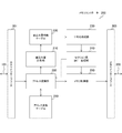
- FIG. 2 is a diagram showing a configuration example of the memory controller 200 according to the first embodiment of the present technology.
- the memory controller 200 includes a write amount measurement unit 210, a write amount information table 220, an averaging processing unit 230, an inter-section copy processing unit 240, an address conversion table 250, an address conversion unit 260, and a memory control unit. And 290.
- the memory controller 200 also includes a host interface 201 for communicating with the host computer 100 and a memory interface 209 for communicating with the memory 300.
- the write amount measurement unit 210 measures the write amount of each page of the memory 300.
- the read or write access unit in the memory cell array of the memory 300 is a page. Therefore, the amount of writing and the number of times of writing for a page are in a proportional relationship, and in the following, they are treated as synonymous.
- the write amount in page units is compared as it is, the comparison target becomes enormous and management becomes complicated, so a management unit called a section is newly introduced as a unit in which a plurality of pages are put together.
- the write amount information table 220 is a table for holding write amount information which is information on the write amount measured by the write amount measurement unit 210. The contents of the write amount information held in the write amount information table 220 will be described later.
- the averaging processing unit 230 selects a target section based on the write amount information held in the write amount information table 220 and performs a wear leveling process of averaging the write amounts of pages included in the target section. It is a thing. For this purpose, the averaging unit 230 changes the physical address assignment in the address conversion of the target section, and changes the physical address of the memory 300 to be written after that to a different one from before.
- the inter-section copy processing unit 240 copies the data written in the target section to the assignment change destination section in order to realize the averaging processing by the averaging processing unit 230.
- the address conversion table 250 is a table for storing the correspondence between the logical address contained in the command from the host computer 100 and the physical address of the memory 300.
- the address conversion unit 260 converts a logical address included in a command from the host computer 100 into a physical address of the memory 300 with reference to the address conversion table 250.
- the memory control unit 290 controls access to the memory 300.
- the memory control unit 290 accesses the memory 300 in accordance with the physical address converted by the address conversion unit 260. Further, the memory control unit 290 accesses the memory 300 so as to copy the data written in the target section of the averaging process to the assignment change destination section in accordance with the instruction from the inter-section copy processing unit 240.
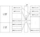
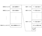
- FIG. 3 is a diagram showing an example of the relationship between sections and pages in the embodiment of the present technology.
- a memory space of 1 GB (gigabyte) is assumed.
- the size of a page which is a read or write access unit is 4 KB (kilobyte).
- the total number of pages in the memory space is 256K pages.
- the writing amount of pages is averaged with a section in which a plurality of pages are grouped as a management unit.
- eight pages are grouped into one section. That is, the amount of data corresponding to one section is 32 KB.
- FIG. 4 is a diagram showing an example of the relationship between the logical section and the physical section in the embodiment of the present technology.
- the logical address space is divided into a user area and a free area and managed.
- the user area is an in-use area allocated as a use area of the user.
- the free area is an unused area not allocated as a used area of the user.
- the user area is an example of the in-use area described in the claims.
- the free area is an example of the unused area described in the claims.
- the user area is a 0.9 GB (921.5 MB) user area
- the free area is a 0.1 GB (102.5 MB) area.
- the user area is a 29488 section of logic sections # 0 to # 29487
- the free area is a 3280 section of logic sections # 29488 to # 32767.
- These logical sections are allocated to physical sections of the memory 300.
- the correspondence between the logical section and the physical section is stored in the address conversion table 250.
- the address conversion unit 260 converts from a logical section to a physical section.
- FIG. 5 is a diagram showing a first example of the write amount information table 220 in the first embodiment of the present technology.
- the write amount information according to the first example is an example of a case where write amount information is provided for every physical section.
- the page writing amount of each of the eight physical pages included in the physical section and the total writing amount of the physical section are stored corresponding to each of the physical sections.
- the page writing amount is a writing amount for each page, and is initialized to zero each time the averaging process is performed.
- the page write amount is used to detect an interpage bias of the write amount in the physical section.
- the total section write amount is a value obtained by adding all the write amounts generated in the physical section, and is not assumed to be initialized. This section total write amount is used to select a physical section in the averaging process.
- the deviation of the page writing amount is detected, for example, when the writing amount is larger than a predetermined threshold value ⁇ as compared with the average value of the page writing amount in a certain section. That is, in the section where writing has occurred, the section is selected as the target section of the averaging process if the following expression is established.
- the threshold value ⁇ is assumed to be, for example, about 1024 to 2048, and it is considered that an appropriate effect can be obtained in this range.
- ⁇ 1024 times (pages)
- the number of repetitions is as follows. However, it is assumed that writing occurred evenly between the page where the writing occurred.
- the deviation of the page writing amount is detected when the writing amount reaches 1170 times.
- the deviation of the page writing amount is detected when the writing amount reaches 2730 times. That is, the smaller the number of specific pages concentrated in the section, the larger the change in the difference with the average write amount. Therefore, it can be understood that the wear leveling process needs to be started earlier as the number of write occurrence pages concentrated in the section decreases even if the total section write amount is the same.
- FIG. 6 is a diagram illustrating a second example of the write amount information table 220 according to the first embodiment of the present technology.
- the total writing amount of the physical section is stored for every physical section.
- other information is stored for each logical section of the user area. That is, the page write amount of each of the eight logical pages included in the logical section is stored corresponding to each of the logical sections of the user area.
- the total writing amount is referred to for both the user area and the free area, since the user area in use is targeted for other information, it is possible to manage only the latter by the logical address.
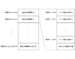
- FIG. 7 is a diagram illustrating an outline example of the averaging process according to the first embodiment of the present technology.
- section A is selected as a logic section having a deviation in the amount of writing between pages.
- the physical section PA is assigned as the physical address of this section A. That is, it is assumed that the physical section PA is stored in the address conversion table 250 corresponding to the logical section LU1 of the user area.
- the section A is selected by the averaging processing unit 230 as a target section of the averaging process.
- the new assignee of section A for the averaging process the section with the smallest total writing amount in the free area is selected.
- section B of the physical section PB is selected as a new assignment destination. That is, it is assumed that the physical section PB is stored in the address conversion table 250 corresponding to the logical section LF1 of the free area.
- the data of the section A stored in the physical section PA is copied to the physical section PB by the inter-section copy processing unit 240. This corrects the page write amount bias of section A that has occurred in physical section PA. Then, the physical section PB is stored corresponding to the logical section LU1 in the address conversion table 250, and the physical section PA is modified to be stored corresponding to the logical section LF1. That is, in this example, the physical section PA is to be managed as a free area.
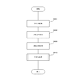
- FIG. 8 is a flowchart showing an example of a processing procedure of memory access processing according to the first embodiment of the present technology.
- the address conversion unit 260 converts a logical address included in the command into a physical address (step S901). Then, according to the converted physical address, the memory control unit 290 accesses the memory 300 via the memory interface 209 (step S902).
- the write amount measurement unit 210 updates the write amount information table 220 according to the write address (step S903). Then, the averaging unit 230 performs the averaging process with reference to the writing amount information table 220 (step S 910).
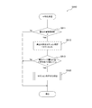
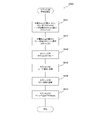
- FIG. 9 is a flowchart illustrating an exemplary processing procedure of the averaging process according to the first embodiment of the present technology.
- the averaging processing unit 230 specifies the section in which the write has occurred (step S912).
- this identified logic section is referred to as section A.
- the averaging unit 230 determines whether the difference between the maximum page writing amount and the average value of the page writing amounts in the section A in which the writing has occurred is larger than the threshold value ⁇ (step S913). Then, if the difference exceeds the threshold value ⁇ and is large (step S913: Yes), the averaging processing unit 230 performs in-section averaging processing (step S920).
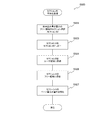
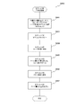
- FIG. 10 is a flowchart illustrating an example of a processing procedure of intra-section averaging processing (step S920) according to the first embodiment of the present technology.
- the averaging unit 230 refers to the write amount information table 220 to select a section in which the total write amount is the smallest in the free area (step S922).
- this selected logic section is referred to as section B.
- the section of the free area having the smallest total writing amount is selected, but the section of the free area having a total writing amount smaller than a predetermined threshold value than the average value of the total writing amounts in the whole is selected. You may do so.
- the inter-section copy processing unit 240 copies the data stored in the section A to the physical section PB of the section B (step S 923).
- the address conversion unit 260 registers the physical section PB allocated to the section B in the user area (step S 924). That is, in the above example, the physical section PB is stored corresponding to the logical address LU1 of the user area of the address conversion table 250.
- the address conversion unit 260 registers the physical section PA allocated to the section A in the free area (step S926). That is, in the above-described example, the physical section PA is stored corresponding to the logical address LF1 of the free area of the address conversion table 250. Further, the write amount measurement unit 210 initializes the page write amount of the section A of the write amount information table 220 to “0” (step S 927).
- page writing in a section is performed by detecting deviation in the amount of writing between pages in a section where writing has occurred and changing the allocation of physical addresses. It is possible to perform quantity averaging.
- the in-section averaging process is performed by changing the assignment of the physical address of the section in which the deviation is detected in the page writing amount.
- the physical address allocation is changed by selecting the section with the smallest total write amount in the free area and replacing the physical address with the section in which the deviation is detected in the page write amount. The Therefore, focusing on the free area, the amount of writing increases.
- the section with the smallest total writing amount in the user area and the section with the largest total writing amount in the free area are exchanged for the free area. Reduce the amount of writing. That is, this inter-section averaging process neutralizes the increase in the writing amount of the free area due to the intra-section averaging process, and averages the writing amount of the entire memory 300.
- the overall configuration of the information processing system and the block configuration of the memory controller are the same as those of the above-described first embodiment, and thus detailed description will be omitted.
- FIG. 11 is a diagram illustrating a first example of the write amount information table 220 according to the second embodiment of the present technology.
- the write amount information according to the first example is an example of a case where write amount information is provided for every physical section.
- a copied flag is stored in addition to the page writing amount and the section total writing amount described in the first embodiment described above corresponding to each of the physical sections.
- the copied flag is a flag set in the section allocated to the user area by the in-section averaging process.
- the section in which the copied flag is set is excluded from the target in the search of the user area in the inter-section averaging process.
- the copied flag is an example of the flag described in the claims.
- FIG. 12 is a diagram illustrating a second example of the write amount information table 220 according to the second embodiment of the present technology.
- the copied flag is stored corresponding to each of the logical sections.
- the role as the copied flag is the same as that of the first example described above.
- FIG. 13 is a diagram showing an outline example of the averaging process according to the second embodiment of the present technology.
- section A is selected as a logical section having a bias of the write amount between pages as the intra-section averaging process
- the data of section A is an inter-section copy processing unit It is copied by 240 to the physical section PB.
- a logical section with the smallest total written amount in the user area and a copied flag of “0” is selected as the section C.
- the physical section PC is assigned as the physical address of this section C. That is, it is assumed that the physical section PC is stored in the address conversion table 250 corresponding to the logical section LU2 of the user area.
- the section having the largest total write amount in the free area is selected and becomes a new allocation destination.
- the section D of the physical section PD is selected as a new assignment destination. That is, it is assumed that the physical section PD is stored in the address conversion table 250 corresponding to the logical section LF2 of the free area.
- the data of the section C stored in the physical section PC is copied by the inter-section copy processing unit 240 to the physical section PD.
- the physical section PD is stored corresponding to the logical section LU2 in the address conversion table 250, and the physical section PC is modified corresponding to the logical section LF2.
- the section with the smallest total writing amount in the user area and the section with the largest total writing amount in the free area are exchanged, and the writing amount in the free area decreases. That is, the increase in the amount of writing in the free area caused by the in-section averaging process is neutralized.
- FIG. 14 is a flow chart showing an example of a processing procedure of averaging processing according to the second embodiment of the present technology.
- the entire process of the memory access process is the same as that of the above-described first embodiment, and thus the description thereof is omitted.
- step S911 When the write amount information is updated in the write amount information table 220 (step S911: Yes), the averaging processing unit 230 specifies the section A in which the writing has occurred (step S912). This point is the same as that of the first embodiment described above.
- the averaging unit 230 determines whether the difference between the maximum page writing amount and the average value of the page writing amounts in the section A in which the writing has occurred is larger than the threshold value ⁇ (step S913). If the difference is larger than the threshold value ⁇ (step S913: YES), the averaging processing unit 230 performs intra-section averaging processing (step S930) and inter-section averaging processing (step S940).
- FIG. 15 is a flowchart illustrating an example of a processing procedure of intra-section averaging processing (step S930) according to the second embodiment of the present technology.
- the averaging unit 230 refers to the write amount information table 220 to select the section B in which the total write amount is the smallest in the free area (step S932). In this example, the section of the free area having the smallest total writing amount is selected, but the section of the free area having a total writing amount smaller than a predetermined threshold value than the average value of the total writing amounts in the whole is selected. You may do so.
- the inter-section copy processing unit 240 copies the data stored in the section A to the physical section PB of the section B (step S933).
- the address conversion unit 260 registers the physical section PB assigned to the section B in the user area (step S934). That is, in the above example, the physical section PB is stored corresponding to the logical address LU1 of the user area of the address conversion table 250.
- the write amount measurement unit 210 sets the copied flag of the section B of the write amount information table 220 to “1” (step S935).
- the address conversion unit 260 registers the physical section PA allocated to the section A in the free area (step S936). That is, in the above-described example, the physical section PA is stored corresponding to the logical address LF1 of the free area of the address conversion table 250.
- the write amount measurement unit 210 initializes the page write amount of the section A of the write amount information table 220 to “0” and resets the copied flag of the section A to “0” (step S 937).
- FIG. 16 is a flowchart illustrating an example of a processing procedure of inter-section averaging processing (step S940) according to the second embodiment of the present technology.
- the averaging processing unit 230 refers to the writing amount information table 220 to select a section in the user area in which the total writing amount is minimum and the copied flag is “0” (step S941).
- this selected logic section is referred to as section C.
- the section of the user area having the smallest total writing amount is selected, the section of the user area having a total writing amount less than a predetermined threshold value than the average value of the total writing amounts in the whole is selected. You may do so.
- that section can be set as a new assignment destination, and the search time can be shortened.
- the averaging unit 230 refers to the write amount information table 220 to select a section having the largest total write amount in the free area (step S 942).
- this selected logic section is referred to as section D.
- the inter-section copy processing unit 240 copies the data stored in the section C to the physical section PD of the section D (step S943).
- the address conversion unit 260 registers the physical section PD allocated to the section D in the user area (step S 944). That is, in the above-described example, the physical section PD is stored corresponding to the logical address LU2 of the user area of the address conversion table 250.
- the address conversion unit 260 registers the physical section PC assigned to the section C in the free area (step S946). That is, in the above-described example, the physical section PC is stored corresponding to the logical address LF2 of the free area of the address conversion table 250. Further, the write amount measurement unit 210 initializes the page write amount of the section C of the write amount information table 220 to “0” (step S 947).
- the section with the smallest total writing amount in the user area is exchanged with the section with the largest total writing amount in the free area. This makes it possible to neutralize the increase in the amount of writing in the free area associated with the in-section averaging process.
- the overall configuration of the information processing system and the block configuration of the memory controller are the same as those of the above-described first embodiment, and thus detailed description will be omitted. Further, the write amount information is the same as that of the second embodiment described above, and thus detailed description will be omitted.
- FIG. 17 is a diagram illustrating an outline example of the averaging process according to the third embodiment of the present technology.
- section A is selected as a logical section having a bias of the write amount between pages as the intra-section averaging process
- the data of section A is an inter-section copy processing unit It is copied by 240 to the physical section PB.
- a logical section with the smallest total written amount in the user area and a copied flag of “0” is selected as the section C. Ru.
- the physical section PC is assigned as the physical address of this section C. That is, it is assumed that the physical section PC is stored in the address conversion table 250 corresponding to the logical section LU2 of the user area.
- the data of the section C stored in the physical section PC was copied to the physical section PD that was in the free area, but in the third embodiment, the data of the section C is Is copied to the physical section PA. That is, the physical section PA is not registered in the free area, and is reused as the section C. Therefore, the physical section PA is changed to be stored corresponding to the logical section LU2 in the address conversion table 250.
- the physical section PC storing the data of the section C is registered in the free area. Therefore, the physical section PC is changed to be stored corresponding to the logical section LF1 in the address conversion table 250. As a result, the physical section PC with a small amount of writing becomes a free area, and the amount of writing in the free area decreases.
- FIG. 18 is a flowchart illustrating an example of a processing procedure of averaging processing according to the third embodiment of the present technology.
- the entire process of the memory access process is the same as that of the above-described first embodiment, and thus the description thereof is omitted.
- step S911 When the write amount information is updated in the write amount information table 220 (step S911: Yes), the averaging processing unit 230 specifies the section A in which the writing has occurred (step S912). This point is the same as that of the first embodiment described above.
- the averaging unit 230 determines whether the difference between the maximum page writing amount and the average value of the page writing amounts in the section A in which the writing has occurred is larger than the threshold value ⁇ (step S913). If the difference is larger than the threshold value ⁇ (step S913: YES), the averaging unit 230 performs intra-section averaging (step S950) and inter-section averaging (step S960).
- FIG. 19 is a flowchart illustrating an example of a processing procedure of intra-section averaging processing (step S950) according to the third embodiment of the present technology.
- the averaging processing unit 230 refers to the write amount information table 220 to select the section B in which the total write amount is the smallest in the free area (step S952). In this example, the section of the free area having the smallest total writing amount is selected, but the section of the free area having a total writing amount smaller than a predetermined threshold value than the average value of the total writing amounts in the whole is selected. You may do so.
- the inter-section copy processing unit 240 copies the data stored in the section A to the physical section PB of the section B (step S953).
- the address conversion unit 260 registers the physical section PB assigned to the section B in the user area (step S954). That is, in the above example, the physical section PB is stored corresponding to the logical address LU1 of the user area of the address conversion table 250.
- the write amount measurement unit 210 sets the copied flag of the section B of the write amount information table 220 to “1” (step S 955).
- FIG. 20 is a flowchart illustrating an example of a processing procedure of inter-section averaging processing (step S960) according to the third embodiment of the present technology.
- the averaging processing unit 230 refers to the writing amount information table 220 to select a section in the user area in which the total writing amount is minimum and the copied flag is “0” (step S 961).
- this selected logic section is referred to as section C.
- the section of the user area having the smallest total writing amount is selected, the section of the user area having a total writing amount less than a predetermined threshold value than the average value of the total writing amounts in the whole is selected. You may do so.
- the inter-section copy processing unit 240 copies the data stored in the section C to the physical section PA of the section A (step S963).
- the address conversion unit 260 registers the physical section PA assigned to the section A in the user area where the section C is (step S 964). That is, in the above-described example, the physical section PA is stored corresponding to the logical address LU2 of the user area of the address conversion table 250.
- the write amount measurement unit 210 initializes the page write amount of the section A of the write amount information table 220, and resets the copied flag of the section A to "0" (step S965).
- the address conversion unit 260 registers the physical section PC assigned to the section C in the free area (step S966). That is, in the above-described example, the physical section PC is stored corresponding to the logical address LF1 of the free area of the address conversion table 250.
- the write amount measurement unit 210 initializes the page write amount of the section C of the write amount information table 220 to “0” (step S 967).
- processing efficiency is improved by reusing the physical section PA in which the target section of the in-section averaging process was stored after the in-section averaging process. It can be done.
- the section of the user area is replaced with the section of the free area after the in-section averaging process.
- the total amount of writing of the section selected as having a deviation of the amount of writing between pages is not so large, replacement with the free area is not necessarily required. Therefore, in the fourth embodiment, when the total writing amount of the sections selected as having the writing amount deviation between pages is not larger than the average value of the total writing amounts of all the sections, The process is simplified without performing the averaging process.
- the overall configuration of the information processing system and the block configuration of the memory controller are the same as those of the above-described first embodiment, and thus detailed description will be omitted. Further, the write amount information is the same as that of the second embodiment described above, and thus detailed description will be omitted.
- FIG. 21 is a flow chart showing an example of a processing procedure of averaging processing according to the fourth embodiment of the present technology.
- the entire process of the memory access process is the same as that of the above-described first embodiment, and thus the description thereof is omitted.
- step S911 When the write amount information is updated in the write amount information table 220 (step S911: Yes), the averaging processing unit 230 specifies the section A in which the writing has occurred (step S912). This point is the same as that of the first embodiment described above.
- the averaging unit 230 determines whether the difference between the maximum page writing amount and the average value of the page writing amounts in the section A in which the writing has occurred is larger than the threshold value ⁇ (step S913). Then, if the difference exceeds the threshold value ⁇ and is large (step S913: Yes), the averaging processing unit 230 performs in-section averaging processing (step S950).
- step S914 If the total writing amount of the section A in which writing has occurred is larger than the average value of all the sections of the total writing amount (step S914: Yes), the averaging processing unit 230 performs the section averaging process (step S960). )I do.
- step S 914: No if the total writing amount of section A is not larger than the average value of all sections (step S 914: No), the address conversion unit 260 registers the physical section PA assigned to section A in the free area. (Step S915). Also, in this case, the write amount measurement unit 210 initializes the page write amount of the section A of the write amount information table 220 to “0” and resets the copied flag of the section A to “0” (step S916). ). In this example, although it is based on whether the total writing amount of section A is larger than the average value of all the sections of the total writing amount, it is also based on whether it is larger than the average value by a predetermined threshold or more. Good.
- step S950 The contents of the processing procedure in the in-section averaging process (step S950) and the inter-section averaging process (step S960) are the same as those in the above-described third embodiment, and thus the description thereof is omitted.
- processing is performed by omitting the inter-section averaging process when the total writing amount of the section in which writing has occurred is not larger than the average value of all sections. Efficiency can be improved.
- FIG. 22 is a diagram showing an example of a configuration of a memory controller 200 according to the fifth embodiment of the present technology.
- the overall configuration of the information processing system is the same as that of the above-described first embodiment, and thus detailed description will be omitted.
- the memory controller 200 in the fifth embodiment includes a random number sequence selection unit 280 in addition to the configuration of the first embodiment described above.
- the random number sequence selection unit 280 selects a different order as the page arrangement order in the section when copying is performed to the section of the allocation change destination by the inter-section copy processing unit 240.
- a random number sequence for defining the page arrangement order in the section is held, for example, in the address conversion table 250.
- the random number sequence selection unit 280 changes the page arrangement order in the section by changing this random number sequence to another one each time copying is performed.
- the random number sequence selection unit 280 is an example of the selection unit described in the claims.
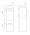
- FIG. 23 is a diagram showing an example of a modification of the page arrangement order in the fifth embodiment of the present technology. As mentioned above, one section is assumed to be composed of eight pages as an example. When the eight pages in the logical section are arranged in the physical section in the memory 300, the order is determined according to the random number sequence.
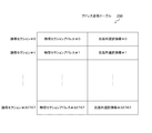
- FIG. 24 is a diagram illustrating an example of a random number sequence according to the fifth embodiment of the present technology.
- page offsets # 0 to # 7 corresponding to eight pages in the physical section are shown in the horizontal direction
- eight random number sequences # 0 to # 7 are shown in the vertical direction.
- Each random number sequence represents page arrangement in the logic section. For example, when using a random number sequence # 2 in a certain section, logical page # 0 is allocated to physical page # 2 and logical page # 4 is allocated to physical page # 6.
- Hadamard matrices are used, and the random number sequences included in these are different from each other. Thus, different random number sequences do not assign the same physical page to the same logical page.
- FIG. 25 is a diagram showing a configuration example of the address conversion table 250 in the fifth embodiment of the present technology.
- the address conversion table 250 in the fifth embodiment holds physical section addresses # 0 to # 32767 and random number sequence selection information # 0 to # 32767 corresponding to the logical sections # 0 to # 32767.
- the physical section address is similar to that of the above-described embodiment, and indicates the physical section on the memory 300 corresponding to the logical section.
- the random number sequence selection information indicates the random number sequence in the fifth embodiment in correspondence with the logic section. It is not necessary to hold the random number sequence itself, but the number of the random number sequence indicating the arrangement order of the logical pages in the physical section may be held. For example, if “3” is held as random number sequence selection information, it is understood that logical page # 6 is allocated to physical page # 5 in the physical section in the above example.
- the random number sequence selection information is an example of information described in the claims.
- the page arrangement order in the section is defined by a random number sequence, and the random number sequence is changed when copying is performed to the assignment change destination section. This can further improve the effect of the averaging process by using a different order as the page arrangement order in the section.
- the processing procedure described in the above embodiment may be regarded as a method having a series of these procedures, and a program for causing a computer to execute the series of procedures or a recording medium storing the program. You may catch it.
- a recording medium for example, a CD (Compact Disc), an MD (Mini Disc), a DVD (Digital Versatile Disc), a memory card, a Blu-ray disc (Blu-ray (registered trademark) Disc) or the like can be used.
- the present technology can also be configured as follows.
- An address conversion unit that performs address conversion between a logical address and a physical address for each management unit in which a plurality of memory access units are grouped.
- a write amount measuring unit that measures the write amount for each of the access units in each of the management units;
- the target management unit is selected from the management units based on the measured write amount, the assignment of the physical address in the address conversion of the target management unit is changed, and the writing of the access unit in the target management unit is performed.
- a memory controller comprising: an averaging unit for averaging amounts.
- the averaging processor selects the management unit as the target management unit when the writing amount of the access unit in the management unit is biased in the management unit. Memory controller.
- the averaging unit when the maximum value of the write amount of the access unit in the management unit is larger than the average value of the write amounts of the access unit in the management unit, is larger than a predetermined threshold value.
- the memory controller according to (1) or (2), wherein a management unit is selected as the target management unit.
- the logical address space of the memory is divided into in-use areas and unused areas and managed,
- the averaging processing unit selects a new allocation destination of the target management unit from the unused area based on the measured writing amount and secures it as the in-use area from (1) to (3).
- Memory controller as described in any one.
- the averaging processing unit sets the management unit whose total number of write amounts of the access unit in the unused area is equal to or less than a predetermined threshold value than the average value of the entire area as a new allocation destination of the target management unit.
- the memory controller according to (4), which selects.
- the averaging processing unit may change the total number of write amounts of the access units in all areas other than the new assignment destination in the area in use to an average value.
- the second management unit is selected as the second management unit which selects the management unit which is smaller than or equal to a predetermined threshold value as the second object management unit, and which has the largest total number of write amounts of the access unit in the unused area.
- the memory controller according to (5) wherein the allocation of the physical address in the address conversion of the second target management unit is changed as a new allocation destination of the above.
- a flag is further provided which holds, for each of the management targets, a notification that the allocation change of the physical address has been made.
- the averaging processing unit sets the flag corresponding to the new allocation destination to the effect of changing the allocation of physical addresses, and selects the second target management unit in the area in use.
- a memory controller given in the above (6) which excludes what has a flag set from selection object.
- the memory controller according to (4), wherein the averaging processing unit allocates the physical address before the assignment change of the target management unit to the area in use and uses it for the other management target.
- the averaging processing unit is configured to change the allocation of the target management unit before changing the total number of the write amounts of the access unit of the target management unit by a predetermined threshold value or more than an average value of the entire management targets.
- the physical address of is allocated to the in-use area and used for the other management target, otherwise the physical address of the target management unit before allocation change is allocated to the unused area (4) Memory controller described in.
- Information for defining the arrangement order of the access unit in the management unit is held for each management unit, and before and after the allocation change of the physical address of the target management unit, the access unit in the target management unit.
- the memory controller according to any one of (1) to (4), further including a selection unit that selects a different order as the arrangement order.
- An address conversion unit that performs address conversion between a logical address and a physical address for each management unit in which a plurality of access units of the memory are grouped;
- a write amount measuring unit that measures the write amount for each of the access units in each of the management units;
- the target management unit is selected from the management units based on the measured write amount, the assignment of the physical address in the address conversion of the target management unit is changed, and the writing of the access unit in the target management unit is performed.
- a memory system comprising: an averaging unit for averaging amounts.
- a host computer that issues a host command to access the memory;
- An address conversion unit that performs address conversion between a logical address of the host command and a physical address of the memory for each management unit in which a plurality of access units of the memory are grouped;
- a write amount measuring unit that measures the write amount for each of the access units in each of the management units;
- the target management unit is selected from the management units based on the measured write amount, the assignment of the physical address in the address conversion of the target management unit is changed, and the writing of the access unit in the target management unit is performed.
- An information processing system comprising: an averaging processing unit that averages amounts.
- An address conversion procedure for performing address conversion between a logical address and a physical address for each management unit in which a plurality of memory access units are grouped.
- a write amount measurement procedure for measuring the write amount for each access unit in each of the management units;
- the target management unit is selected from the management units based on the measured write amount, the assignment of the physical address in the address conversion of the target management unit is changed, and the writing of the access unit in the target management unit is performed.
- a memory control method comprising: averaging procedure for averaging quantities.
- host computer 100 host computer 200 memory controller 201 host interface 209 memory interface 210 write amount measurement unit 220 write amount information table 230 averaging processing unit 240 inter-section copy processing unit 250 address conversion table 260 address conversion unit 280 random number sequence selection unit 290 memory control unit 300 memory 400 memory system
Landscapes
- Engineering & Computer Science (AREA)
- Theoretical Computer Science (AREA)
- Physics & Mathematics (AREA)
- General Engineering & Computer Science (AREA)
- General Physics & Mathematics (AREA)
- Human Computer Interaction (AREA)
- Memory System (AREA)
- Techniques For Improving Reliability Of Storages (AREA)
Abstract
アクセス単位であるページ毎に書込み回数にばらつきが生じ得るメモリにおいて、効率のよいウェアレベリング処理を行う。 アドレス変換部は、メモリのアクセス単位を複数まとめた管理単位ごとに、ホストコマンドの論理アドレスとメモリの物理アドレスとの間でアドレス変換を行う。書込み量計測部は、管理単位のそれぞれにおいてアクセス単位ごとの書込み量を計測する。平均化処理部は、書込み量計測部によって計測された書込み量に基づいて、管理単位のうちから対象管理単位を選択して、その対象管理単位のアドレス変換における物理アドレスの割当を変更する。そして、平均化処理部は、対象管理単位におけるアクセス単位の書込み量を平均化させる処理を行う。
Description
本技術は、メモリコントローラに関する。詳しくは、メモリに対する書込みを制御するメモリコントローラ、メモリシステム、情報処理システム、および、これらにおける処理方法ならびに当該方法をコンピュータに実行させるプログラムに関する。
書込み回数の上限がある不揮発性メモリを搭載した不揮発性記憶装置では、書込み回数を平均化するウェアレベリング処理が行われる。不揮発性メモリの一例であるNANDフラッシュメモリでは、データの上書きは不可能であり、読出しおよび書込みのアクセス単位であるページを複数まとめたブロックを消去単位としており、ウェアレベリング処理はブロック単位で行われる。例えば、書込み頻度が高いブロックの消去回数が100の倍数になる度にウェアレベリング処理を行う不揮発性メモリが提案されている(例えば、特許文献1参照。)。
上述の従来技術では、ブロックの消去回数を計測して、その消去回数に基づいてウェアレベリング処理を行っている。この従来技術が前提とするNANDフラッシュメモリでは、データの上書きが不可能なため、ブロック内のページ間に書込み回数のばらつきは発生せず、ブロックの消去回数を平均化することが目的となる。一方、データの上書きが可能な不揮発性メモリを想定すると、読出しおよび書込みのアクセス単位であるページ毎に書込み回数にばらつきが生じるおそれがある。しかしながら、ページサイズはブロックサイズよりも小さいため、ページの書込み回数を個別に扱ってウェアレベリング処理を行うとその対象数が膨大となり、管理が煩雑になるという問題がある。
本技術はこのような状況に鑑みて生み出されたものであり、アクセス単位であるページ毎に書込み回数にばらつきが生じ得るメモリにおいて、効率のよいウェアレベリング処理を行うことを目的とする。
本技術は、上述の問題点を解消するためになされたものであり、その第1の側面は、メモリのアクセス単位を複数まとめた管理単位ごとに論理アドレスと物理アドレスとの間でアドレス変換を行うアドレス変換部と、上記管理単位のそれぞれにおいて上記アクセス単位ごとの書込み量を計測する書込み量計測部と、上記計測された書込み量に基づいて上記管理単位のうちから対象管理単位を選択して当該対象管理単位の上記アドレス変換における物理アドレスの割当を変更して、上記対象管理単位における上記アクセス単位の書込み量を平均化させる平均化処理部とを具備するメモリコントローラ、メモリシステム、情報処理システム、および、そのメモリ制御方法である。これにより、書込み量に基づいて選択された対象管理単位の物理アドレスの割当を変更して、その対象管理単位におけるアクセス単位の書込み量を平均化させるという作用をもたらす。
また、この第1の側面において、上記平均化処理部は、上記管理単位における上記アクセス単位の書込み量がその管理単位において偏りを生じた場合に、その管理単位を上記対象管理単位として選択するようにしてもよい。これにより、管理単位におけるアクセス単位の書込み量に偏りを生じた場合に、その管理単位を対象管理単位として選択するという作用をもたらす。
また、この第1の側面において、上記平均化処理部は、上記管理単位における上記アクセス単位の書込み量の最大値がその管理単位における上記アクセス単位の書込み量の平均値よりも所定の閾値を超えて大きい場合に、その管理単位を上記対象管理単位として選択するようにしてもよい。これにより、管理単位におけるアクセス単位の書込み量の最大値が、その管理単位におけるアクセス単位の書込み量の平均値よりも所定の閾値を超えて大きい場合にその管理単位を対象管理単位として選択するという作用をもたらす。
また、この第1の側面において、上記メモリの論理アドレス空間は、使用中領域と未使用領域とに分けて管理され、上記平均化処理部は、上記計測された書込み量に基づいて上記対象管理単位の新たな割当先を上記未使用領域から選択して上記使用中領域として確保するようにしてもよい。これにより、論理アドレス空間の管理を容易にするという作用をもたらす。
また、この第1の側面において、上記平均化処理部は、上記未使用領域において上記アクセス単位の書込み量の総数が全体の平均値よりも所定の閾値以下となる上記管理単位を上記対象管理単位の新たな割当先として選択するようにしてもよい。これにより、書込み量の総数が全体の平均値よりも所定の閾値以下となる管理単位を、対象管理単位の新たな割当先として選択するという作用をもたらす。
また、この第1の側面において、上記平均化処理部は、上記対象管理単位の物理アドレスの割当が変更された際、上記使用中領域において上記新たな割当先以外で上記アクセス単位の書込み量の総数が全体の平均値よりも所定の閾値以下となる上記管理単位を第2の対象管理単位として選択し、上記未使用領域において上記アクセス単位の書込み量の総数が最大となる上記管理単位を上記第2の対象管理単位の新たな割当先として選択して、上記第2の対象管理単位の上記アドレス変換における物理アドレスの割当を変更するようにしてもよい。これにより、対象管理単位の物理アドレス割当変更に伴う未使用領域における書込み量の増大を中和するという作用をもたらす。
また、この第1の側面において、物理アドレスの割当変更対象となった旨を上記管理対象ごとに保持するフラグをさらに具備し、上記平均化処理部は、上記新たな割当先に対応する上記フラグを物理アドレスの割当変更対象となった旨にセットし、上記使用中領域において上記第2の対象管理単位を選択する際に上記フラグがセットされているものを選択対象から除外するようにしてもよい。これにより、新たな割当先となった管理対象がすぐに第2の対象管理単位として選択されることを回避するという作用をもたらす。
また、この第1の側面において、上記平均化処理部は、上記対象管理単位の割当変更前の物理アドレスを上記未使用領域に割り当ててもよく、また、上記対象管理単位の割当変更前の物理アドレスを上記使用中領域に割り当てて他の上記管理対象のために使用するようにしてもよい。
また、この第1の側面において、上記平均化処理部は、上記対象管理単位の上記アクセス単位の書込み量の総数が上記管理対象の全体の平均値よりも所定の閾値以上大きい場合には上記対象管理単位の割当変更前の物理アドレスを上記使用中領域に割り当てて他の上記管理対象のために使用し、それ以外の場合には上記対象管理単位の割当変更前の物理アドレスを上記未使用領域に割り当てるようにしてもよい。これにより、対象管理単位の総書込み量に応じて使用中領域または未使用領域に割り当てるという作用をもたらす。
また、この第1の側面において、上記管理単位における上記アクセス単位の配置順序を規定する情報を上記管理単位ごとに保持して、上記対象管理単位の物理アドレスの割当変更の前後においては上記対象管理単位における上記アクセス単位の配置順序として異なる順序を選択する選択部をさらに具備してもよい。これにより、対象管理単位の物理アドレスの割当変更の前後において、アクセス単位の配置順序を異なるものにするという作用をもたらす。
また、この第1の側面において、上記アクセス単位の配置順序を規定する情報は、互いに異なる複数の乱数列であってもよい。これにより、乱数列を用いてアクセス単位の配置順序を規定するという作用をもたらす。
本技術によれば、アクセス単位であるページ毎に書込み回数にばらつきが生じ得るメモリにおいて、効率のよいウェアレベリング処理を行うことができるという優れた効果を奏し得る。なお、ここに記載された効果は必ずしも限定されるものではなく、本開示中に記載されたいずれかの効果であってもよい。
以下、本技術を実施するための形態(以下、実施の形態と称する)について説明する。説明は以下の順序により行う。
1.第1の実施の形態(セクション内のページ間の書込み量を平均化する例)
2.第2の実施の形態(フリー領域の書込み量を減らす処理を加えた例)
3.第3の実施の形態(平均化処理の対象セクションを再利用する例)
4.第4の実施の形態(平均化処理の対象セクションの書込み量が多い場合に再利用する例)
5.第5の実施の形態(乱数列を変更してセクション内のページ順序を変化させる例)
1.第1の実施の形態(セクション内のページ間の書込み量を平均化する例)
2.第2の実施の形態(フリー領域の書込み量を減らす処理を加えた例)
3.第3の実施の形態(平均化処理の対象セクションを再利用する例)
4.第4の実施の形態(平均化処理の対象セクションの書込み量が多い場合に再利用する例)
5.第5の実施の形態(乱数列を変更してセクション内のページ順序を変化させる例)
<1.第1の実施の形態>
[情報処理システムの構成]
図1は、本技術の実施の形態における情報処理システムの一構成例を示す図である。この情報処理システムは、ホストコンピュータ100と、メモリコントローラ200と、メモリ300とから構成される。メモリコントローラ200およびメモリ300はメモリシステム400を構成する。
[情報処理システムの構成]
図1は、本技術の実施の形態における情報処理システムの一構成例を示す図である。この情報処理システムは、ホストコンピュータ100と、メモリコントローラ200と、メモリ300とから構成される。メモリコントローラ200およびメモリ300はメモリシステム400を構成する。
ホストコンピュータ100は、メモリ300に対してデータのリード処理およびライト処理等を指令するコマンドを発行するものである。このホストコンピュータ100は、ホストコンピュータ100としての処理を実行するプロセッサと、メモリコントローラ200との間のやりとりを行うためのコントローラインターフェースとを備える。ホストコンピュータ100とメモリコントローラ200との間は信号線109によって接続される。
メモリコントローラ200は、ホストコンピュータ100からのコマンドに従って、メモリ300に対するリクエスト制御を行うものである。メモリコントローラ200とメモリ300との間は信号線309によって接続される。
メモリ300は、制御部およびメモリセルアレイを備える。このメモリ300の制御部は、メモリコントローラ200からのリクエストに従ってメモリセルへのアクセスを行う。メモリ300のメモリセルアレイは、複数のメモリセルからなるメモリセルアレイであり、ビット毎に2値の何れかの値を記憶するメモリセル、または、複数ビット毎に多値の何れかの値を記憶するメモリセルが2次元状(マトリクス状)に多数配列されている。このメモリセルアレイは、複数バイトサイズを有するページを読出しまたは書込みのアクセス単位とし、消去することなくデータの上書きが可能な不揮発性メモリ(NVM:Non-Volatile Memory)を想定する。
[メモリコントローラの構成]
図2は、本技術の第1の実施の形態におけるメモリコントローラ200の一構成例を示す図である。このメモリコントローラ200は、書込み量計測部210と、書込み量情報テーブル220と、平均化処理部230と、セクション間コピー処理部240と、アドレス変換テーブル250と、アドレス変換部260と、メモリ制御部290とを備える。また、このメモリコントローラ200は、ホストコンピュータ100との間のやりとりを行うためのホストインターフェース201と、メモリ300との間のやりとりを行うためのメモリインターフェース209とを備える。
図2は、本技術の第1の実施の形態におけるメモリコントローラ200の一構成例を示す図である。このメモリコントローラ200は、書込み量計測部210と、書込み量情報テーブル220と、平均化処理部230と、セクション間コピー処理部240と、アドレス変換テーブル250と、アドレス変換部260と、メモリ制御部290とを備える。また、このメモリコントローラ200は、ホストコンピュータ100との間のやりとりを行うためのホストインターフェース201と、メモリ300との間のやりとりを行うためのメモリインターフェース209とを備える。
書込み量計測部210は、メモリ300の各ページの書込み量を計測するものである。上述のように、メモリ300のメモリセルアレイにおける読出しまたは書込みのアクセス単位はページである。したがって、ページに関する書込み量と書込み回数は比例関係にあり、以下では同義であるものとして取り扱う。一方、ページを単位とする書込み量をそのまま比較した場合には比較対象が膨大となり管理が煩雑になるため、複数のページをまとめた単位として、セクションと称する管理単位を新たに導入する。
書込み量情報テーブル220は、書込み量計測部210によって計測された書込み量に関する情報である書込み量情報を保持するテーブルである。この書込み量情報テーブル220に保持される書込み量情報の内容については後述する。
平均化処理部230は、書込み量情報テーブル220に保持される書込み量情報に基づいて対象となるセクションを選択して、その対象セクションに含まれるページの書込み量を平均化するウェアレベリング処理を行うものである。そのために、この平均化処理部230は、その対象セクションのアドレス変換における物理アドレスの割当を変更して、それ以降に書込みがなされるメモリ300の物理アドレスをそれまでとは異なるものに変更する。
セクション間コピー処理部240は、平均化処理部230による平均化処理を実現するために、対象セクションに書き込まれているデータを、割当変更先のセクションにコピーする処理を行うものである。
アドレス変換テーブル250は、ホストコンピュータ100からのコマンドに含まれる論理アドレスとメモリ300の物理アドレスとの対応関係を記憶するテーブルである。アドレス変換部260は、アドレス変換テーブル250を参照して、ホストコンピュータ100からのコマンドに含まれる論理アドレスをメモリ300の物理アドレスに変換するものである。
メモリ制御部290は、メモリ300に対するアクセスを制御するものである。このメモリ制御部290は、アドレス変換部260によって変換された物理アドレスに従って、メモリ300にアクセスを行う。また、メモリ制御部290は、セクション間コピー処理部240からの指示に従って、平均化処理の対象セクションに書き込まれているデータを割当変更先のセクションにコピーするように、メモリ300にアクセスを行う。
[セクション]
図3は、本技術の実施の形態におけるセクションとページの関係例を示す図である。ここでは、1GB(ギガバイト)のメモリ空間を想定する。そして、このメモリ空間において、読出しまたは書込みのアクセス単位であるページのサイズを4KB(キロバイト)とする。この場合、メモリ空間における総ページ数は256Kページとなる。メモリ300におけるページ間の書込み量の偏りを検出するためには、これら256Kページの書込み量を比較してそれらを平均化させることが考えられるが、その場合には比較量が膨大となり管理が煩雑となる。
図3は、本技術の実施の形態におけるセクションとページの関係例を示す図である。ここでは、1GB(ギガバイト)のメモリ空間を想定する。そして、このメモリ空間において、読出しまたは書込みのアクセス単位であるページのサイズを4KB(キロバイト)とする。この場合、メモリ空間における総ページ数は256Kページとなる。メモリ300におけるページ間の書込み量の偏りを検出するためには、これら256Kページの書込み量を比較してそれらを平均化させることが考えられるが、その場合には比較量が膨大となり管理が煩雑となる。
そこで、この実施の形態では、複数のページをまとめたセクションを管理単位としてページの書込み量の平均化を行う。この例では、8ページをまとめて1つのセクションとする。すなわち、1セクションに相当するデータ量は32KBとなる。また、1GBのメモリ空間はセクション#0から#32767の32K(=32768)セクションに分割して管理される。
図4は、本技術の実施の形態における論理セクションと物理セクションの関係例を示す図である。論理アドレス空間は、ユーザ領域とフリー領域とに分けて管理される。ユーザ領域は、ユーザの使用領域として割り当てられた使用中領域である。一方、フリー領域は、ユーザの使用領域として割り当てられていない未使用領域である。なお、ユーザ領域は、特許請求の範囲に記載の使用中領域の一例である。また,フリー領域は、特許請求の範囲に記載の未使用領域の一例である。
この例では、ユーザ領域は0.9GB(921.5MB)のユーザ領域であり、フリー領域は0.1GB(102.5MB)の領域である。このとき、ユーザ領域は論理セクション#0から#29487の29488セクションであり、フリー領域は論理セクション#29488から#32767の3280セクションである。
これら論理セクションは、メモリ300の物理セクションに割り当てられる。この論理セクションと物理セクションの対応関係はアドレス変換テーブル250に記憶される。このアドレス変換テーブル250に従って、アドレス変換部260が論理セクションから物理セクションに変換を行う。
[書込み量情報]
図5は、本技術の第1の実施の形態における書込み量情報テーブル220の第1の例を示す図である。この第1の例による書込み量情報は、全ての物理セクション毎に書込み量情報を有する場合の例である。この第1の例では、物理セクションのそれぞれに対応して、その物理セクションに含まれる8つの物理ページの各々のページ書込み量と、その物理セクションの総書込み量とを記憶する。
図5は、本技術の第1の実施の形態における書込み量情報テーブル220の第1の例を示す図である。この第1の例による書込み量情報は、全ての物理セクション毎に書込み量情報を有する場合の例である。この第1の例では、物理セクションのそれぞれに対応して、その物理セクションに含まれる8つの物理ページの各々のページ書込み量と、その物理セクションの総書込み量とを記憶する。
ページ書込み量はページ毎の書込み量であり、平均化処理が行われる度にゼロに初期化される。ページ書込み量は、物理セクション内の書込み量のページ間の偏りを検出するために用いられる。
セクション総書込み量はその物理セクションに発生した書込み量を全て加算した値であり、初期化されることは想定していない。このセクション総書込み量は、平均化処理において物理セクションを選択するために用いられる。
ページ書込み量の偏りは、例えば、あるセクションにおけるページ書込み量の平均値と比較して、書込み量が所定の閾値αを超えて大きい場合に検出される。すなわち、書込みが発生したセクションにおいて、次式が成立した場合に、そのセクションは平均化処理の対象セクションとして選択される。
最大ページ書込み量 - ページ書込み量の平均値 > α
最大ページ書込み量 - ページ書込み量の平均値 > α
上式において、閾値αは、例えば1024乃至2048程度であることが想定され、この範囲において適切な効果が得られるものと考えられる。一例として、セクション内の特定のページに書込みが発生した場合を想定して、その書込み発生ページのページ数を変化させ、平均書込み量との差分がα=1024回(ページ)に達するまでの書込み繰り返し回数を求めると以下のようになる。ただし、その書込み発生ページ間では、均等に書込みが生じたものと仮定する。
書込み発生ページ数=1: 1170- 146=1024
書込み発生ページ数=2: 1365- 341=1024
書込み発生ページ数=3: 1638- 614=1024
書込み発生ページ数=4: 2048-1024=1024
書込み発生ページ数=5: 2730-1706=1024
書込み発生ページ数=6: 4096-3072=1024
書込み発生ページ数=7: 8192-7168=1024
書込み発生ページ数=8: 0(セクション内の全ページに均等)
書込み発生ページ数=1: 1170- 146=1024
書込み発生ページ数=2: 1365- 341=1024
書込み発生ページ数=3: 1638- 614=1024
書込み発生ページ数=4: 2048-1024=1024
書込み発生ページ数=5: 2730-1706=1024
書込み発生ページ数=6: 4096-3072=1024
書込み発生ページ数=7: 8192-7168=1024
書込み発生ページ数=8: 0(セクション内の全ページに均等)
これによれば、例えば、書込みが特定の1ページに集中した場合には、その書込み量が1170回になった時点でページ書込み量の偏りが検出される。一方、書込みが特定の5ページに集中した場合には、その書込み量が2730回になった時点でページ書込み量の偏りが検出される。すなわち、セクション内で集中した特定のページ数が少ないほど、平均書込み量との差分の変化が大きい。したがって、セクション総書込み量が同じであっても、セクション内で集中した書込み発生ページ数が少ないほど、ウェアレベリング処理を早く開始する必要があることがわかる。
図6は、本技術の第1の実施の形態における書込み量情報テーブル220の第2の例を示す図である。この第2の例では、上述の第1の例と同様に、全ての物理セクション毎に物理セクションの総書込み量を記憶する。一方、この第2の例では、上述の第1の例と異なり、それ以外の情報はユーザ領域の論理セクション毎に記憶される。すなわち、ユーザ領域の論理セクションのそれぞれに対応して、その論理セクションに含まれる8つの論理ページの各々のページ書込み量を記憶する。
総書込み量はユーザ領域およびフリー領域の両者について参照されるが、それ以外の情報については使用中のユーザ領域が対象となるため、後者のみを論理アドレスにより管理することが可能である。
[動作]
図7は、本技術の第1の実施の形態における平均化処理の概要例を示す図である。ここでは、ページ間の書込み量の偏りを有する論理セクションとしてセクションAが選択された場合を想定する。その際、このセクションAの物理アドレスとして物理セクションPAが割り当てられていたものとする。すなわち、アドレス変換テーブル250には、ユーザ領域の論理セクションLU1に対応して物理セクションPAが記憶されていたものとする。
図7は、本技術の第1の実施の形態における平均化処理の概要例を示す図である。ここでは、ページ間の書込み量の偏りを有する論理セクションとしてセクションAが選択された場合を想定する。その際、このセクションAの物理アドレスとして物理セクションPAが割り当てられていたものとする。すなわち、アドレス変換テーブル250には、ユーザ領域の論理セクションLU1に対応して物理セクションPAが記憶されていたものとする。
ここで、セクションAにおいてページ書込み量の偏りが検出されると、セクションAは平均化処理部230によって平均化処理の対象セクションとして選択される。平均化処理のためにセクションAの新たな割当先は、フリー領域において総書込み量が最小のセクションが選択される。この例では、物理セクションPBのセクションBが新たな割当先として選択されたものとする。すなわち、アドレス変換テーブル250には、フリー領域の論理セクションLF1に対応して物理セクションPBが記憶されていたものとする。
物理セクションPAに記憶されていたセクションAのデータは、セクション間コピー処理部240によって物理セクションPBにコピーされる。これにより、物理セクションPAにおいて生じていたセクションAのページ書込み量の偏りが是正される。そして、アドレス変換テーブル250における論理セクションLU1に対応して物理セクションPBが記憶され、論理セクションLF1に対応して物理セクションPAが記憶されるように変更される。すなわち、この例では、物理セクションPAはフリー領域として管理されるようになる。
図8は、本技術の第1の実施の形態におけるメモリアクセス処理の処理手順例を示す流れ図である。
ホストコンピュータ100からメモリアクセスのコマンドを受け取ると、アドレス変換部260は、コマンドに含まれる論理アドレスを物理アドレスに変換する(ステップS901)。そして、この変換された物理アドレスに従って、メモリ制御部290はメモリインターフェース209を介してメモリ300にアクセスを行う(ステップS902)。
その際、メモリ300に対する書込みがされた場合には、書込み量計測部210は、書込みアドレスに従って書込み量情報テーブル220を更新する(ステップS903)。そして、平均化処理部230は、書込み量情報テーブル220を参照して平均化処理を行う(ステップS910)。
図9は、本技術の第1の実施の形態における平均化処理の処理手順例を示す流れ図である。
書込み量情報テーブル220において書込み量情報が更新されると(ステップS911:Yes)、平均化処理部230は、その書込みが発生したセクションを特定する(ステップS912)。以下ではこの特定された論理セクションをセクションAと称する。
平均化処理部230は、その書込みが発生したセクションAにおいて、最大ページ書込み量とページ書込み量の平均値との差分が、閾値αを超えて大きいか否かを判断する(ステップS913)。そして、その差分が閾値αを超えて大きい場合には(ステップS913:Yes)、平均化処理部230はセクション内平均化処理を行う(ステップS920)。
図10は、本技術の第1の実施の形態におけるセクション内平均化処理(ステップS920)の処理手順例を示す流れ図である。
平均化処理部230は、書込み量情報テーブル220を参照して、フリー領域において総書込み量が最小のセクションを選択する(ステップS922)。以下ではこの選択された論理セクションをセクションBと称する。なお、この例では、総書込み量が最小のフリー領域のセクションを選択しているが、全体における総書込み量の平均値よりも所定の閾値以下の総書込み量を有するフリー領域のセクションを選択するようにしてもよい。
そして、セクション間コピー処理部240は、セクションAに記憶されているデータをセクションBの物理セクションPBにコピーする(ステップS923)。
アドレス変換部260は、セクションBに割り当てられていた物理セクションPBをユーザ領域に登録する(ステップS924)。すなわち、上述の例において、アドレス変換テーブル250のユーザ領域の論理アドレスLU1に対応して物理セクションPBを記憶する。
また、アドレス変換部260は、セクションAに割り当てられていた物理セクションPAをフリー領域に登録する(ステップS926)。すなわち、上述の例において、アドレス変換テーブル250のフリー領域の論理アドレスLF1に対応して物理セクションPAを記憶する。また、書込み量計測部210は、書込み量情報テーブル220のセクションAのページ書込み量を「0」に初期化する(ステップS927)。
このように、本技術の第1の実施の形態によれば、書込みが発生したセクションにおけるページ間の書込み量の偏りを検出して、物理アドレスの割当を変更することにより、セクション内のページ書込み量の平均化処理を行うことができる。
<2.第2の実施の形態>
上述の第1の実施の形態では、ページ書込み量に偏りが検出されたセクションの物理アドレスの割当てを変更することによりセクション内平均化処理を行っていた。このセクション内平均化処理では、フリー領域において総書込み量が最小となるセクションを選択して、ページ書込み量に偏りが検出されたセクションと物理アドレスを入れ換えることにより、物理アドレスの割当てを変更していた。そのため、フリー領域に着目すると、書込み量は増加することになる。
上述の第1の実施の形態では、ページ書込み量に偏りが検出されたセクションの物理アドレスの割当てを変更することによりセクション内平均化処理を行っていた。このセクション内平均化処理では、フリー領域において総書込み量が最小となるセクションを選択して、ページ書込み量に偏りが検出されたセクションと物理アドレスを入れ換えることにより、物理アドレスの割当てを変更していた。そのため、フリー領域に着目すると、書込み量は増加することになる。
そこで、この第2の実施の形態では、セクション内平均化処理の後に、ユーザ領域において総書込み量が最小のセクションと、フリー領域において総書込み量が最大のセクションとを交換することによりフリー領域の書込み量の減少を図る。すなわち、このセクション間平均化処理は、セクション内平均化処理によるフリー領域の書込み量増加を中和して、メモリ300全体としての書込み量を平均化するものである。
なお、情報処理システムとしての全体構成およびメモリコントローラのブロック構成については、上述の第1の実施の形態と同様であるため、詳細な説明は省略する。
[書込み量情報]
セクション間平均化処理の際に、ユーザ領域において総書込み量が最小のセクションを選択する際、セクション内平均化処理によって割り当てられた直後のセクションが選択されてしまうと、意図した平均化が行われなくなるおそれがある。そのため、この第2の実施の形態では、書込み情報として、セクション内平均化処理によるコピーが行われた直後であることを示すコピー済フラグを設け、これにより、セクション間平均化処理においてそのセクションが選択されることを回避する。
セクション間平均化処理の際に、ユーザ領域において総書込み量が最小のセクションを選択する際、セクション内平均化処理によって割り当てられた直後のセクションが選択されてしまうと、意図した平均化が行われなくなるおそれがある。そのため、この第2の実施の形態では、書込み情報として、セクション内平均化処理によるコピーが行われた直後であることを示すコピー済フラグを設け、これにより、セクション間平均化処理においてそのセクションが選択されることを回避する。
図11は、本技術の第2の実施の形態における書込み量情報テーブル220の第1の例を示す図である。この第1の例による書込み量情報は、全ての物理セクション毎に書込み量情報を有する場合の例である。この第1の例では、物理セクションのそれぞれに対応して、上述の第1の実施の形態において説明したページ書込み量およびセクション総書込み量に加えて、コピー済フラグを記憶する。
コピー済フラグは、セクション内平均化処理によりユーザ領域に割り当てられたセクションに設定されるフラグである。このコピー済フラグが設定されているセクションは、セクション間平均化処理におけるユーザ領域の検索の際に対象から除外される。なお、コピー済フラグは、特許請求の範囲に記載のフラグの一例である。
図12は、本技術の第2の実施の形態における書込み量情報テーブル220の第2の例を示す図である。この第2の例では、上述の第1の実施の形態において説明したページ書込み量およびセクション総書込み量に加えて、論理セクションのそれぞれに対応して、コピー済フラグを記憶する。コピー済フラグとしての役割は、上述の第1の例と同様である。
[動作]
図13は、本技術の第2の実施の形態における平均化処理の概要例を示す図である。ここでは、上述の第1の実施の形態と同様に、セクション内平均化処理として、ページ間の書込み量の偏りを有する論理セクションとしてセクションAが選択され、セクションAのデータはセクション間コピー処理部240によって物理セクションPBにコピーされる。
図13は、本技術の第2の実施の形態における平均化処理の概要例を示す図である。ここでは、上述の第1の実施の形態と同様に、セクション内平均化処理として、ページ間の書込み量の偏りを有する論理セクションとしてセクションAが選択され、セクションAのデータはセクション間コピー処理部240によって物理セクションPBにコピーされる。
また、この第2の実施の形態においては、セクション内平均化処理の後に、ユーザ領域において総書込み量が最小であってコピー済フラグが「0」である論理セクションがセクションCとして選択される。その際、このセクションCの物理アドレスとして物理セクションPCが割り当てられていたものとする。すなわち、アドレス変換テーブル250には、ユーザ領域の論理セクションLU2に対応して物理セクションPCが記憶されていたものとする。
一方、フリー領域において総書込み量が最大のセクションが選択され、新たな割当先となる。この例では、物理セクションPDのセクションDが新たな割当先として選択されたものとする。すなわち、アドレス変換テーブル250には、フリー領域の論理セクションLF2に対応して物理セクションPDが記憶されていたものとする。
物理セクションPCに記憶されていたセクションCのデータは、セクション間コピー処理部240によって物理セクションPDにコピーされる。そして、アドレス変換テーブル250における論理セクションLU2に対応して物理セクションPDが記憶され、論理セクションLF2に対応して物理セクションPCが記憶されるように変更される。これにより、ユーザ領域において総書込み量が最小のセクションと、フリー領域において総書込み量が最大のセクションとが交換されて、フリー領域の書込み量が減少する。すなわち、セクション内平均化処理により生じたフリー領域の書込み量の増加が、中和されたことになる。
図14は、本技術の第2の実施の形態における平均化処理の処理手順例を示す流れ図である。なお、メモリアクセス処理の全体処理については上述の第1の実施の形態と同様であるため、説明を省略する。
書込み量情報テーブル220において書込み量情報が更新されると(ステップS911:Yes)、平均化処理部230は、その書込みが発生したセクションAを特定する(ステップS912)。この点は上述の第1の実施の形態と同様である。
平均化処理部230は、その書込みが発生したセクションAにおいて、最大ページ書込み量とページ書込み量の平均値との差分が、閾値αを超えて大きいか否かを判断する(ステップS913)。そして、その差分が閾値αを超えて大きい場合には(ステップS913:Yes)、平均化処理部230はセクション内平均化処理(ステップS930)およびセクション間平均化処理(ステップS940)を行う。
図15は、本技術の第2の実施の形態におけるセクション内平均化処理(ステップS930)の処理手順例を示す流れ図である。
平均化処理部230は、書込み量情報テーブル220を参照して、フリー領域において総書込み量が最小のセクションBを選択する(ステップS932)。なお、この例では、総書込み量が最小のフリー領域のセクションを選択しているが、全体における総書込み量の平均値よりも所定の閾値以下の総書込み量を有するフリー領域のセクションを選択するようにしてもよい。
そして、セクション間コピー処理部240は、セクションAに記憶されているデータをセクションBの物理セクションPBにコピーする(ステップS933)。
アドレス変換部260は、セクションBに割り当てられていた物理セクションPBをユーザ領域に登録する(ステップS934)。すなわち、上述の例において、アドレス変換テーブル250のユーザ領域の論理アドレスLU1に対応して物理セクションPBを記憶する。
また、書込み量計測部210は、書込み量情報テーブル220のセクションBのコピー済フラグを「1」に設定する(ステップS935)。
また、アドレス変換部260は、セクションAに割り当てられていた物理セクションPAをフリー領域に登録する(ステップS936)。すなわち、上述の例において、アドレス変換テーブル250のフリー領域の論理アドレスLF1に対応して物理セクションPAを記憶する。
また、書込み量計測部210は、書込み量情報テーブル220のセクションAのページ書込み量を「0」に初期化するとともに、セクションAのコピー済フラグを「0」にリセットする(ステップS937)。
図16は、本技術の第2の実施の形態におけるセクション間平均化処理(ステップS940)の処理手順例を示す流れ図である。
平均化処理部230は、書込み量情報テーブル220を参照して、ユーザ領域において総書込み量が最小であって、かつ、コピー済フラグが「0」であるセクションを選択する(ステップS941)。以下ではこの選択された論理セクションをセクションCと称する。なお、この例では、総書込み量が最小のユーザ領域のセクションを選択しているが、全体における総書込み量の平均値よりも所定の閾値以下の総書込み量を有するユーザ領域のセクションを選択するようにしてもよい。この場合、平均値よりも所定の閾値以下の総書込み量を有するセクションが検索された時点で、そのセクションを新たな割当先とすることができ、検索時間を短縮することが可能である。
平均化処理部230は、書込み量情報テーブル220を参照して、フリー領域において総書込み量が最大のセクションを選択する(ステップS942)。以下ではこの選択された論理セクションをセクションDと称する。
そして、セクション間コピー処理部240は、セクションCに記憶されているデータをセクションDの物理セクションPDにコピーする(ステップS943)。
アドレス変換部260は、セクションDに割り当てられていた物理セクションPDをユーザ領域に登録する(ステップS944)。すなわち、上述の例において、アドレス変換テーブル250のユーザ領域の論理アドレスLU2に対応して物理セクションPDを記憶する。
また、アドレス変換部260は、セクションCに割り当てられていた物理セクションPCをフリー領域に登録する(ステップS946)。すなわち、上述の例において、アドレス変換テーブル250のフリー領域の論理アドレスLF2に対応して物理セクションPCを記憶する。また、書込み量計測部210は、書込み量情報テーブル220のセクションCのページ書込み量を「0」に初期化する(ステップS947)。
このように、本技術の第2の実施の形態では、セクション内平均化処理の後に、ユーザ領域において総書込み量が最小のセクションと、フリー領域において総書込み量が最大のセクションとを交換する。これにより、セクション内平均化処理に伴うフリー領域の書込み量の増大を中和することができる。
<3.第3の実施の形態>
上述の第2の実施の形態では、セクション内平均化処理の後に、ユーザ領域において総書込み量が最小のセクションと、フリー領域において総書込み量が最大のセクションとを交換することにより、フリー領域の書込み量の減少を図っていた。この場合、セクション内平均化処理に伴うフリー領域の書込み量の増大を中和するためには高い効果が得られるが、フリー領域において総書込み量が最大となるセクションを選択する必要があった。一方、セクション内平均化処理の対象セクションが記憶されていた物理セクションPAの書込み量によっては、物理セクションPAをフリー領域として登録しても書込み量の減少にあまり寄与しない場合も生じ得る。そこで、この第3の実施の形態では、セクション内平均化処理の後にフリー領域において総書込み量が最大のセクションを検索することなく、セクション内平均化処理の対象セクションが記憶されていた物理セクションPAを再利用して、処理の簡略化を図る。
上述の第2の実施の形態では、セクション内平均化処理の後に、ユーザ領域において総書込み量が最小のセクションと、フリー領域において総書込み量が最大のセクションとを交換することにより、フリー領域の書込み量の減少を図っていた。この場合、セクション内平均化処理に伴うフリー領域の書込み量の増大を中和するためには高い効果が得られるが、フリー領域において総書込み量が最大となるセクションを選択する必要があった。一方、セクション内平均化処理の対象セクションが記憶されていた物理セクションPAの書込み量によっては、物理セクションPAをフリー領域として登録しても書込み量の減少にあまり寄与しない場合も生じ得る。そこで、この第3の実施の形態では、セクション内平均化処理の後にフリー領域において総書込み量が最大のセクションを検索することなく、セクション内平均化処理の対象セクションが記憶されていた物理セクションPAを再利用して、処理の簡略化を図る。
なお、情報処理システムとしての全体構成およびメモリコントローラのブロック構成については、上述の第1の実施の形態と同様であるため、詳細な説明は省略する。また、書込み量情報については、上述の第2の実施の形態と同様であるため、詳細な説明は省略する。
[動作]
図17は、本技術の第3の実施の形態における平均化処理の概要例を示す図である。ここでは、上述の第1の実施の形態と同様に、セクション内平均化処理として、ページ間の書込み量の偏りを有する論理セクションとしてセクションAが選択され、セクションAのデータはセクション間コピー処理部240によって物理セクションPBにコピーされる。
図17は、本技術の第3の実施の形態における平均化処理の概要例を示す図である。ここでは、上述の第1の実施の形態と同様に、セクション内平均化処理として、ページ間の書込み量の偏りを有する論理セクションとしてセクションAが選択され、セクションAのデータはセクション間コピー処理部240によって物理セクションPBにコピーされる。
また、上述の第2の実施の形態と同様に、セクション内平均化処理の後に、ユーザ領域において総書込み量が最小であってコピー済フラグが「0」である論理セクションがセクションCとして選択される。その際、このセクションCの物理アドレスとして物理セクションPCが割り当てられていたものとする。すなわち、アドレス変換テーブル250には、ユーザ領域の論理セクションLU2に対応して物理セクションPCが記憶されていたものとする。
上述の第2の実施の形態においては物理セクションPCに記憶されていたセクションCのデータはフリー領域にあった物理セクションPDにコピーされていたが、この第3の実施の形態ではセクションCのデータは物理セクションPAにコピーされる。すなわち、物理セクションPAはフリー領域に登録されず、セクションCとして再利用される。そのため、アドレス変換テーブル250における論理セクションLU2に対応して物理セクションPAが記憶されるように変更される。
一方、セクションCのデータを記憶していた物理セクションPCは、フリー領域に登録される。そのため、アドレス変換テーブル250における論理セクションLF1に対応して物理セクションPCが記憶されるように変更される。これにより、書込み量の小さい物理セクションPCがフリー領域となり、フリー領域の書込み量が減少する。
図18は、本技術の第3の実施の形態における平均化処理の処理手順例を示す流れ図である。なお、メモリアクセス処理の全体処理については上述の第1の実施の形態と同様であるため、説明を省略する。
書込み量情報テーブル220において書込み量情報が更新されると(ステップS911:Yes)、平均化処理部230は、その書込みが発生したセクションAを特定する(ステップS912)。この点は上述の第1の実施の形態と同様である。
平均化処理部230は、その書込みが発生したセクションAにおいて、最大ページ書込み量とページ書込み量の平均値との差分が、閾値αを超えて大きいか否かを判断する(ステップS913)。そして、その差分が閾値αを超えて大きい場合には(ステップS913:Yes)、平均化処理部230はセクション内平均化処理(ステップS950)およびセクション間平均化処理(ステップS960)を行う。
図19は、本技術の第3の実施の形態におけるセクション内平均化処理(ステップS950)の処理手順例を示す流れ図である。
平均化処理部230は、書込み量情報テーブル220を参照して、フリー領域において総書込み量が最小のセクションBを選択する(ステップS952)。なお、この例では、総書込み量が最小のフリー領域のセクションを選択しているが、全体における総書込み量の平均値よりも所定の閾値以下の総書込み量を有するフリー領域のセクションを選択するようにしてもよい。
そして、セクション間コピー処理部240は、セクションAに記憶されているデータをセクションBの物理セクションPBにコピーする(ステップS953)。
アドレス変換部260は、セクションBに割り当てられていた物理セクションPBをユーザ領域に登録する(ステップS954)。すなわち、上述の例において、アドレス変換テーブル250のユーザ領域の論理アドレスLU1に対応して物理セクションPBを記憶する。
また、書込み量計測部210は、書込み量情報テーブル220のセクションBのコピー済フラグを「1」に設定する(ステップS955)。
図20は、本技術の第3の実施の形態におけるセクション間平均化処理(ステップS960)の処理手順例を示す流れ図である。
平均化処理部230は、書込み量情報テーブル220を参照して、ユーザ領域において総書込み量が最小であって、かつ、コピー済フラグが「0」であるセクションを選択する(ステップS961)。以下ではこの選択された論理セクションをセクションCと称する。なお、この例では、総書込み量が最小のユーザ領域のセクションを選択しているが、全体における総書込み量の平均値よりも所定の閾値以下の総書込み量を有するユーザ領域のセクションを選択するようにしてもよい。
そして、セクション間コピー処理部240は、セクションCに記憶されているデータをセクションAの物理セクションPAにコピーする(ステップS963)。
アドレス変換部260は、セクションAに割り当てられていた物理セクションPAを、セクションCのあったユーザ領域に登録する(ステップS964)。すなわち、上述の例において、アドレス変換テーブル250のユーザ領域の論理アドレスLU2に対応して物理セクションPAを記憶する。
また、書込み量計測部210は、書込み量情報テーブル220のセクションAのページ書込み量を初期化するとともに、セクションAのコピー済フラグを「0」にリセットする(ステップS965)。
一方、アドレス変換部260は、セクションCに割り当てられていた物理セクションPCをフリー領域に登録する(ステップS966)。すなわち、上述の例において、アドレス変換テーブル250のフリー領域の論理アドレスLF1に対応して物理セクションPCを記憶する。
また、書込み量計測部210は、書込み量情報テーブル220のセクションCのページ書込み量を「0」に初期化する(ステップS967)。
このように、本技術の第3の実施の形態では、セクション内平均化処理の後に、セクション内平均化処理の対象セクションが記憶されていた物理セクションPAを再利用することにより、処理効率を向上させることができる。
<4.第4の実施の形態>
上述の第2および第3の実施の形態では、セクション内平均化処理の後に、ユーザ領域のセクションとフリー領域のセクションとの間で入換えを行っていた。しかしながら、ページ間の書込み量の偏りを有するものとして選択されたセクションの総書込み量がそれほど多くない場合には、フリー領域との入換えは必ずしも必要ではない。そこで、この第4の実施の形態では、ページ間の書込み量の偏りを有するものとして選択されたセクションの総書込み量が全セクションの総書込み量の平均値よりも多くない場合には、セクション間平均化処理を行わずに、処理の簡略化を図る。
上述の第2および第3の実施の形態では、セクション内平均化処理の後に、ユーザ領域のセクションとフリー領域のセクションとの間で入換えを行っていた。しかしながら、ページ間の書込み量の偏りを有するものとして選択されたセクションの総書込み量がそれほど多くない場合には、フリー領域との入換えは必ずしも必要ではない。そこで、この第4の実施の形態では、ページ間の書込み量の偏りを有するものとして選択されたセクションの総書込み量が全セクションの総書込み量の平均値よりも多くない場合には、セクション間平均化処理を行わずに、処理の簡略化を図る。
なお、情報処理システムとしての全体構成およびメモリコントローラのブロック構成については、上述の第1の実施の形態と同様であるため、詳細な説明は省略する。また、書込み量情報については、上述の第2の実施の形態と同様であるため、詳細な説明は省略する。
[動作]
図21は、本技術の第4の実施の形態における平均化処理の処理手順例を示す流れ図である。なお、メモリアクセス処理の全体処理については上述の第1の実施の形態と同様であるため、説明を省略する。
図21は、本技術の第4の実施の形態における平均化処理の処理手順例を示す流れ図である。なお、メモリアクセス処理の全体処理については上述の第1の実施の形態と同様であるため、説明を省略する。
書込み量情報テーブル220において書込み量情報が更新されると(ステップS911:Yes)、平均化処理部230は、その書込みが発生したセクションAを特定する(ステップS912)。この点は上述の第1の実施の形態と同様である。
平均化処理部230は、その書込みが発生したセクションAにおいて、最大ページ書込み量とページ書込み量の平均値との差分が、閾値αを超えて大きいか否かを判断する(ステップS913)。そして、その差分が閾値αを超えて大きい場合には(ステップS913:Yes)、平均化処理部230はセクション内平均化処理(ステップS950)を行う。
そして、書込みが発生したセクションAの総書込み量が、総書込み量の全セクションの平均値よりも大きい場合には(ステップS914:Yes)、平均化処理部230はセクション間平均化処理(ステップS960)を行う。一方、セクションAの総書込み量が、全セクションの平均値よりも多くない場合には(ステップS914:No)、アドレス変換部260は、セクションAに割り当てられていた物理セクションPAをフリー領域に登録する(ステップS915)。また、この場合、書込み量計測部210は、書込み量情報テーブル220のセクションAのページ書込み量を「0」に初期化するとともに、セクションAのコピー済フラグを「0」にリセットする(ステップS916)。なお、この例では、セクションAの総書込み量が総書込み量の全セクションの平均値よりも大きいか否かを基準としているが、平均値よりも所定の閾値以上大きいか否かを基準としてもよい。
なお、セクション内平均化処理(ステップS950)およびセクション間平均化処理(ステップS960)における処理手順の内容については、上述の第3の実施の形態と同様であるため、説明を省略する。
このように、本技術の第4の実施の形態によれば、書込みが発生したセクションの総書込み量が全セクションの平均値よりも多くない場合に、セクション間平均化処理を省くことにより、処理効率を向上させることができる。
<5.第5の実施の形態>
上述の第1乃至第4の実施の形態では、セクション間で入換えを行うことにより、セクション内のページ書込み量の平均化を図っていた。したがって、セクション内のページの順序については入換えの前後において変化がなかった。これに対し、この第5の実施の形態では、セクション内のページの順序を変更することにより、平均化処理の効果をさらに向上させる。
上述の第1乃至第4の実施の形態では、セクション間で入換えを行うことにより、セクション内のページ書込み量の平均化を図っていた。したがって、セクション内のページの順序については入換えの前後において変化がなかった。これに対し、この第5の実施の形態では、セクション内のページの順序を変更することにより、平均化処理の効果をさらに向上させる。
[メモリコントローラの構成]
図22は、本技術の第5の実施の形態におけるメモリコントローラ200の一構成例を示す図である。なお、情報処理システムとしての全体構成については、上述の第1の実施の形態と同様であるため、詳細な説明は省略する。
図22は、本技術の第5の実施の形態におけるメモリコントローラ200の一構成例を示す図である。なお、情報処理システムとしての全体構成については、上述の第1の実施の形態と同様であるため、詳細な説明は省略する。
この第5の実施の形態におけるメモリコントローラ200は、上述の第1の実施の形態の構成に加えて、乱数列選択部280を備える。この乱数列選択部280は、セクション間コピー処理部240によって割当変更先のセクションにコピーが行われる際、セクション内のページ配置順序として異なる順序を選択するものである。セクション内のページ配置順序を規定するための乱数列は、例えばアドレス変換テーブル250に保持される。乱数列選択部280は、コピーが行われる度にこの乱数列を別のものに変更することにより、セクション内のページ配置順序を変更する。なお、乱数列選択部280は、特許請求の範囲に記載の選択部の一例である。
[乱数列]
図23は、本技術の第5の実施の形態におけるページ配置順序の変更態様の例を示す図である。上述のように、1つのセクションは、一例として8つのページから構成されるものと想定する。論理セクション内の8つのページは、メモリ300における物理セクションに配置される際、乱数列に従って順序が決定される。
図23は、本技術の第5の実施の形態におけるページ配置順序の変更態様の例を示す図である。上述のように、1つのセクションは、一例として8つのページから構成されるものと想定する。論理セクション内の8つのページは、メモリ300における物理セクションに配置される際、乱数列に従って順序が決定される。
図24は、本技術の第5の実施の形態における乱数列の一例を示す図である。ここでは、横方向に物理セクション内の8ページに相当するページオフセット#0乃至#7が示され、縦方向に8つの乱数列#0乃至#7が示されている。
各乱数列は、論理セクション内のページ配置を表している。例えば、あるセクションにおいて乱数列#2を使用する場合、論理ページ#0は物理ページ#2に割り当てられ、論理ページ#4は物理ページ#6に割り当てられることになる。
なお、この例ではアダマール行列を用いており、これに含まれる乱数列は互いに異なる。したがって、異なる乱数列によって同じ物理ページが同じ論理ページに割り当てられることはない。
図25は、本技術の第5の実施の形態におけるアドレス変換テーブル250の構成例を示す図である。この第5の実施の形態におけるアドレス変換テーブル250は、論理セクション#0乃至#32767に対応して、物理セクションアドレス#0乃至#32767と、乱数列選択情報#0乃至#32767とを保持する。
物理セクションアドレスは、上述の実施の形態と同様であり、論理セクションに対応するメモリ300上の物理セクションを示すものである。
乱数列選択情報は、この第5の実施の形態における乱数列を、論理セクションに対応してそれぞれ示すものである。乱数列自体を保持する必要はなく、物理セクション内の論理ページの配置順序を示す乱数列の番号を保持すればよい。例えば、乱数列選択情報として「3」が保持されていれば、上述の例において論理ページ#6は物理セクション内の物理ページ#5に割り当てられることが分かる。なお、乱数列選択情報は、特許請求の範囲に記載の情報の一例である。
このように、本技術の第5の実施の形態では、セクション内のページ配置順序を乱数列によって定義して、割当変更先のセクションにコピーが行われる際に乱数列を変更する。これにより、セクション内のページ配置順序として異なる順序を使用することにより、平均化処理の効果をさらに向上させることができる。
なお、上述の実施の形態は本技術を具現化するための一例を示したものであり、実施の形態における事項と、特許請求の範囲における発明特定事項とはそれぞれ対応関係を有する。同様に、特許請求の範囲における発明特定事項と、これと同一名称を付した本技術の実施の形態における事項とはそれぞれ対応関係を有する。ただし、本技術は実施の形態に限定されるものではなく、その要旨を逸脱しない範囲において実施の形態に種々の変形を施すことにより具現化することができる。
また、上述の実施の形態において説明した処理手順は、これら一連の手順を有する方法として捉えてもよく、また、これら一連の手順をコンピュータに実行させるためのプログラム乃至そのプログラムを記憶する記録媒体として捉えてもよい。この記録媒体として、例えば、CD(Compact Disc)、MD(MiniDisc)、DVD(Digital Versatile Disc)、メモリカード、ブルーレイディスク(Blu-ray(登録商標)Disc)等を用いることができる。
なお、本明細書に記載された効果はあくまで例示であって、限定されるものではなく、また、他の効果があってもよい。
なお、本技術は以下のような構成もとることができる。
(1)メモリのアクセス単位を複数まとめた管理単位ごとに論理アドレスと物理アドレスとの間でアドレス変換を行うアドレス変換部と、
前記管理単位のそれぞれにおいて前記アクセス単位ごとの書込み量を計測する書込み量計測部と、
前記計測された書込み量に基づいて前記管理単位のうちから対象管理単位を選択して当該対象管理単位の前記アドレス変換における物理アドレスの割当を変更して、前記対象管理単位における前記アクセス単位の書込み量を平均化させる平均化処理部と
を具備するメモリコントローラ。
(2)前記平均化処理部は、前記管理単位における前記アクセス単位の書込み量がその管理単位において偏りを生じた場合に、その管理単位を前記対象管理単位として選択する
前記(1)に記載のメモリコントローラ。
(3)前記平均化処理部は、前記管理単位における前記アクセス単位の書込み量の最大値がその管理単位における前記アクセス単位の書込み量の平均値よりも所定の閾値を超えて大きい場合に、その管理単位を前記対象管理単位として選択する
前記(1)または(2)に記載のメモリコントローラ。
(4)前記メモリの論理アドレス空間は、使用中領域と未使用領域とに分けて管理され、
前記平均化処理部は、前記計測された書込み量に基づいて前記対象管理単位の新たな割当先を前記未使用領域から選択して前記使用中領域として確保する
前記(1)から(3)のいずれかに記載のメモリコントローラ。
(5)前記平均化処理部は、前記未使用領域において前記アクセス単位の書込み量の総数が全体の平均値よりも所定の閾値以下となる前記管理単位を前記対象管理単位の新たな割当先として選択する
前記(4)に記載のメモリコントローラ。
(6)前記平均化処理部は、前記対象管理単位の物理アドレスの割当が変更された際、前記使用中領域において前記新たな割当先以外で前記アクセス単位の書込み量の総数が全体の平均値よりも所定の閾値以下となる前記管理単位を第2の対象管理単位として選択し、前記未使用領域において前記アクセス単位の書込み量の総数が最大となる前記管理単位を前記第2の対象管理単位の新たな割当先として選択して、前記第2の対象管理単位の前記アドレス変換における物理アドレスの割当を変更する
前記(5)に記載のメモリコントローラ。
(7)物理アドレスの割当変更対象となった旨を前記管理対象ごとに保持するフラグをさらに具備し、
前記平均化処理部は、前記新たな割当先に対応する前記フラグを物理アドレスの割当変更対象となった旨にセットし、前記使用中領域において前記第2の対象管理単位を選択する際に前記フラグがセットされているものを選択対象から除外する
前記(6)に記載のメモリコントローラ。
(8)前記平均化処理部は、前記対象管理単位の割当変更前の物理アドレスを前記未使用領域に割り当てる
前記(4)に記載のメモリコントローラ。
(9)前記平均化処理部は、前記対象管理単位の割当変更前の物理アドレスを前記使用中領域に割り当てて他の前記管理対象のために使用する
前記(4)に記載のメモリコントローラ。
(10)前記平均化処理部は、前記対象管理単位の前記アクセス単位の書込み量の総数が前記管理対象の全体の平均値よりも所定の閾値以上大きい場合には前記対象管理単位の割当変更前の物理アドレスを前記使用中領域に割り当てて他の前記管理対象のために使用し、それ以外の場合には前記対象管理単位の割当変更前の物理アドレスを前記未使用領域に割り当てる
前記(4)に記載のメモリコントローラ。
(11)前記管理単位における前記アクセス単位の配置順序を規定する情報を前記管理単位ごとに保持して、前記対象管理単位の物理アドレスの割当変更の前後においては前記対象管理単位における前記アクセス単位の配置順序として異なる順序を選択する選択部をさらに具備する前記(1)から(4)のいずれかに記載のメモリコントローラ。
(12)前記アクセス単位の配置順序を規定する情報は、互いに異なる複数の乱数列である前記(11)に記載のメモリコントローラ。
(13)メモリと、
前記メモリのアクセス単位を複数まとめた管理単位ごとに論理アドレスと物理アドレスとの間でアドレス変換を行うアドレス変換部と、
前記管理単位のそれぞれにおいて前記アクセス単位ごとの書込み量を計測する書込み量計測部と、
前記計測された書込み量に基づいて前記管理単位のうちから対象管理単位を選択して当該対象管理単位の前記アドレス変換における物理アドレスの割当を変更して、前記対象管理単位における前記アクセス単位の書込み量を平均化させる平均化処理部と
を具備するメモリシステム。
(14)メモリと、
前記メモリにアクセスするためのホストコマンドを発行するホストコンピュータと、
前記メモリのアクセス単位を複数まとめた管理単位ごとに前記ホストコマンドの論理アドレスと前記メモリの物理アドレスとの間でアドレス変換を行うアドレス変換部と、
前記管理単位のそれぞれにおいて前記アクセス単位ごとの書込み量を計測する書込み量計測部と、
前記計測された書込み量に基づいて前記管理単位のうちから対象管理単位を選択して当該対象管理単位の前記アドレス変換における物理アドレスの割当を変更して、前記対象管理単位における前記アクセス単位の書込み量を平均化させる平均化処理部と
を具備する情報処理システム。
(15)メモリのアクセス単位を複数まとめた管理単位ごとに論理アドレスと物理アドレスとの間でアドレス変換を行うアドレス変換手順と、
前記管理単位のそれぞれにおいて前記アクセス単位ごとの書込み量を計測する書込み量計測手順と、
前記計測された書込み量に基づいて前記管理単位のうちから対象管理単位を選択して当該対象管理単位の前記アドレス変換における物理アドレスの割当を変更して、前記対象管理単位における前記アクセス単位の書込み量を平均化させる平均化処理手順と
を具備するメモリ制御方法。
(1)メモリのアクセス単位を複数まとめた管理単位ごとに論理アドレスと物理アドレスとの間でアドレス変換を行うアドレス変換部と、
前記管理単位のそれぞれにおいて前記アクセス単位ごとの書込み量を計測する書込み量計測部と、
前記計測された書込み量に基づいて前記管理単位のうちから対象管理単位を選択して当該対象管理単位の前記アドレス変換における物理アドレスの割当を変更して、前記対象管理単位における前記アクセス単位の書込み量を平均化させる平均化処理部と
を具備するメモリコントローラ。
(2)前記平均化処理部は、前記管理単位における前記アクセス単位の書込み量がその管理単位において偏りを生じた場合に、その管理単位を前記対象管理単位として選択する
前記(1)に記載のメモリコントローラ。
(3)前記平均化処理部は、前記管理単位における前記アクセス単位の書込み量の最大値がその管理単位における前記アクセス単位の書込み量の平均値よりも所定の閾値を超えて大きい場合に、その管理単位を前記対象管理単位として選択する
前記(1)または(2)に記載のメモリコントローラ。
(4)前記メモリの論理アドレス空間は、使用中領域と未使用領域とに分けて管理され、
前記平均化処理部は、前記計測された書込み量に基づいて前記対象管理単位の新たな割当先を前記未使用領域から選択して前記使用中領域として確保する
前記(1)から(3)のいずれかに記載のメモリコントローラ。
(5)前記平均化処理部は、前記未使用領域において前記アクセス単位の書込み量の総数が全体の平均値よりも所定の閾値以下となる前記管理単位を前記対象管理単位の新たな割当先として選択する
前記(4)に記載のメモリコントローラ。
(6)前記平均化処理部は、前記対象管理単位の物理アドレスの割当が変更された際、前記使用中領域において前記新たな割当先以外で前記アクセス単位の書込み量の総数が全体の平均値よりも所定の閾値以下となる前記管理単位を第2の対象管理単位として選択し、前記未使用領域において前記アクセス単位の書込み量の総数が最大となる前記管理単位を前記第2の対象管理単位の新たな割当先として選択して、前記第2の対象管理単位の前記アドレス変換における物理アドレスの割当を変更する
前記(5)に記載のメモリコントローラ。
(7)物理アドレスの割当変更対象となった旨を前記管理対象ごとに保持するフラグをさらに具備し、
前記平均化処理部は、前記新たな割当先に対応する前記フラグを物理アドレスの割当変更対象となった旨にセットし、前記使用中領域において前記第2の対象管理単位を選択する際に前記フラグがセットされているものを選択対象から除外する
前記(6)に記載のメモリコントローラ。
(8)前記平均化処理部は、前記対象管理単位の割当変更前の物理アドレスを前記未使用領域に割り当てる
前記(4)に記載のメモリコントローラ。
(9)前記平均化処理部は、前記対象管理単位の割当変更前の物理アドレスを前記使用中領域に割り当てて他の前記管理対象のために使用する
前記(4)に記載のメモリコントローラ。
(10)前記平均化処理部は、前記対象管理単位の前記アクセス単位の書込み量の総数が前記管理対象の全体の平均値よりも所定の閾値以上大きい場合には前記対象管理単位の割当変更前の物理アドレスを前記使用中領域に割り当てて他の前記管理対象のために使用し、それ以外の場合には前記対象管理単位の割当変更前の物理アドレスを前記未使用領域に割り当てる
前記(4)に記載のメモリコントローラ。
(11)前記管理単位における前記アクセス単位の配置順序を規定する情報を前記管理単位ごとに保持して、前記対象管理単位の物理アドレスの割当変更の前後においては前記対象管理単位における前記アクセス単位の配置順序として異なる順序を選択する選択部をさらに具備する前記(1)から(4)のいずれかに記載のメモリコントローラ。
(12)前記アクセス単位の配置順序を規定する情報は、互いに異なる複数の乱数列である前記(11)に記載のメモリコントローラ。
(13)メモリと、
前記メモリのアクセス単位を複数まとめた管理単位ごとに論理アドレスと物理アドレスとの間でアドレス変換を行うアドレス変換部と、
前記管理単位のそれぞれにおいて前記アクセス単位ごとの書込み量を計測する書込み量計測部と、
前記計測された書込み量に基づいて前記管理単位のうちから対象管理単位を選択して当該対象管理単位の前記アドレス変換における物理アドレスの割当を変更して、前記対象管理単位における前記アクセス単位の書込み量を平均化させる平均化処理部と
を具備するメモリシステム。
(14)メモリと、
前記メモリにアクセスするためのホストコマンドを発行するホストコンピュータと、
前記メモリのアクセス単位を複数まとめた管理単位ごとに前記ホストコマンドの論理アドレスと前記メモリの物理アドレスとの間でアドレス変換を行うアドレス変換部と、
前記管理単位のそれぞれにおいて前記アクセス単位ごとの書込み量を計測する書込み量計測部と、
前記計測された書込み量に基づいて前記管理単位のうちから対象管理単位を選択して当該対象管理単位の前記アドレス変換における物理アドレスの割当を変更して、前記対象管理単位における前記アクセス単位の書込み量を平均化させる平均化処理部と
を具備する情報処理システム。
(15)メモリのアクセス単位を複数まとめた管理単位ごとに論理アドレスと物理アドレスとの間でアドレス変換を行うアドレス変換手順と、
前記管理単位のそれぞれにおいて前記アクセス単位ごとの書込み量を計測する書込み量計測手順と、
前記計測された書込み量に基づいて前記管理単位のうちから対象管理単位を選択して当該対象管理単位の前記アドレス変換における物理アドレスの割当を変更して、前記対象管理単位における前記アクセス単位の書込み量を平均化させる平均化処理手順と
を具備するメモリ制御方法。
100 ホストコンピュータ
200 メモリコントローラ
201 ホストインターフェース
209 メモリインターフェース
210 書込み量計測部
220 書込み量情報テーブル
230 平均化処理部
240 セクション間コピー処理部
250 アドレス変換テーブル
260 アドレス変換部
280 乱数列選択部
290 メモリ制御部
300 メモリ
400 メモリシステム
200 メモリコントローラ
201 ホストインターフェース
209 メモリインターフェース
210 書込み量計測部
220 書込み量情報テーブル
230 平均化処理部
240 セクション間コピー処理部
250 アドレス変換テーブル
260 アドレス変換部
280 乱数列選択部
290 メモリ制御部
300 メモリ
400 メモリシステム
Claims (15)
- メモリのアクセス単位を複数まとめた管理単位ごとに論理アドレスと物理アドレスとの間でアドレス変換を行うアドレス変換部と、
前記管理単位のそれぞれにおいて前記アクセス単位ごとの書込み量を計測する書込み量計測部と、
前記計測された書込み量に基づいて前記管理単位のうちから対象管理単位を選択して当該対象管理単位の前記アドレス変換における物理アドレスの割当を変更して、前記対象管理単位における前記アクセス単位の書込み量を平均化させる平均化処理部と
を具備するメモリコントローラ。 - 前記平均化処理部は、前記管理単位における前記アクセス単位の書込み量がその管理単位において偏りを生じた場合に、その管理単位を前記対象管理単位として選択する
請求項1記載のメモリコントローラ。 - 前記平均化処理部は、前記管理単位における前記アクセス単位の書込み量の最大値がその管理単位における前記アクセス単位の書込み量の平均値よりも所定の閾値を超えて大きい場合に、その管理単位を前記対象管理単位として選択する
請求項1記載のメモリコントローラ。 - 前記メモリの論理アドレス空間は、使用中領域と未使用領域とに分けて管理され、
前記平均化処理部は、前記計測された書込み量に基づいて前記対象管理単位の新たな割当先を前記未使用領域から選択して前記使用中領域として確保する
請求項1記載のメモリコントローラ。 - 前記平均化処理部は、前記未使用領域において前記アクセス単位の書込み量の総数が全体の平均値よりも所定の閾値以下となる前記管理単位を前記対象管理単位の新たな割当先として選択する
請求項4記載のメモリコントローラ。 - 前記平均化処理部は、前記対象管理単位の物理アドレスの割当が変更された際、前記使用中領域において前記新たな割当先以外で前記アクセス単位の書込み量の総数が全体の平均値よりも所定の閾値以下となる前記管理単位を第2の対象管理単位として選択し、前記未使用領域において前記アクセス単位の書込み量の総数が最大となる前記管理単位を前記第2の対象管理単位の新たな割当先として選択して、前記第2の対象管理単位の前記アドレス変換における物理アドレスの割当を変更する
請求項5記載のメモリコントローラ。 - 物理アドレスの割当変更対象となった旨を前記管理対象ごとに保持するフラグをさらに具備し、
前記平均化処理部は、前記新たな割当先に対応する前記フラグを物理アドレスの割当変更対象となった旨にセットし、前記使用中領域において前記第2の対象管理単位を選択する際に前記フラグがセットされているものを選択対象から除外する
請求項6記載のメモリコントローラ。 - 前記平均化処理部は、前記対象管理単位の割当変更前の物理アドレスを前記未使用領域に割り当てる
請求項4記載のメモリコントローラ。 - 前記平均化処理部は、前記対象管理単位の割当変更前の物理アドレスを前記使用中領域に割り当てて他の前記管理対象のために使用する
請求項4記載のメモリコントローラ。 - 前記平均化処理部は、前記対象管理単位の前記アクセス単位の書込み量の総数が前記管理対象の全体の平均値よりも所定の閾値以上大きい場合には前記対象管理単位の割当変更前の物理アドレスを前記使用中領域に割り当てて他の前記管理対象のために使用し、それ以外の場合には前記対象管理単位の割当変更前の物理アドレスを前記未使用領域に割り当てる
請求項4記載のメモリコントローラ。 - 前記管理単位における前記アクセス単位の配置順序を規定する情報を前記管理単位ごとに保持して、前記対象管理単位の物理アドレスの割当変更の前後においては前記対象管理単位における前記アクセス単位の配置順序として異なる順序を選択する選択部をさらに具備する請求項1記載のメモリコントローラ。
- 前記アクセス単位の配置順序を規定する情報は、互いに異なる複数の乱数列である請求項11記載のメモリコントローラ。
- メモリと、
前記メモリのアクセス単位を複数まとめた管理単位ごとに論理アドレスと物理アドレスとの間でアドレス変換を行うアドレス変換部と、
前記管理単位のそれぞれにおいて前記アクセス単位ごとの書込み量を計測する書込み量計測部と、
前記計測された書込み量に基づいて前記管理単位のうちから対象管理単位を選択して当該対象管理単位の前記アドレス変換における物理アドレスの割当を変更して、前記対象管理単位における前記アクセス単位の書込み量を平均化させる平均化処理部と
を具備するメモリシステム。 - メモリと、
前記メモリにアクセスするためのホストコマンドを発行するホストコンピュータと、
前記メモリのアクセス単位を複数まとめた管理単位ごとに前記ホストコマンドの論理アドレスと前記メモリの物理アドレスとの間でアドレス変換を行うアドレス変換部と、
前記管理単位のそれぞれにおいて前記アクセス単位ごとの書込み量を計測する書込み量計測部と、
前記計測された書込み量に基づいて前記管理単位のうちから対象管理単位を選択して当該対象管理単位の前記アドレス変換における物理アドレスの割当を変更して、前記対象管理単位における前記アクセス単位の書込み量を平均化させる平均化処理部と
を具備する情報処理システム。 - メモリのアクセス単位を複数まとめた管理単位ごとに論理アドレスと物理アドレスとの間でアドレス変換を行うアドレス変換手順と、
前記管理単位のそれぞれにおいて前記アクセス単位ごとの書込み量を計測する書込み量計測手順と、
前記計測された書込み量に基づいて前記管理単位のうちから対象管理単位を選択して当該対象管理単位の前記アドレス変換における物理アドレスの割当を変更して、前記対象管理単位における前記アクセス単位の書込み量を平均化させる平均化処理手順と
を具備するメモリ制御方法。
Priority Applications (2)
| Application Number | Priority Date | Filing Date | Title |
|---|---|---|---|
| US16/629,615 US11269546B2 (en) | 2017-07-18 | 2018-04-03 | Memory controller, memory system, information processing system, and memory control method |
| JP2019530874A JP7063900B2 (ja) | 2017-07-18 | 2018-04-03 | ウェアレベリング処理を行うメモリコントローラ |
Applications Claiming Priority (2)
| Application Number | Priority Date | Filing Date | Title |
|---|---|---|---|
| JP2017138782 | 2017-07-18 | ||
| JP2017-138782 | 2017-07-18 |
Publications (1)
| Publication Number | Publication Date |
|---|---|
| WO2019017017A1 true WO2019017017A1 (ja) | 2019-01-24 |
Family
ID=65015908
Family Applications (1)
| Application Number | Title | Priority Date | Filing Date |
|---|---|---|---|
| PCT/JP2018/014241 Ceased WO2019017017A1 (ja) | 2017-07-18 | 2018-04-03 | ウェアレベリング処理を行うメモリコントローラ |
Country Status (3)
| Country | Link |
|---|---|
| US (1) | US11269546B2 (ja) |
| JP (1) | JP7063900B2 (ja) |
| WO (1) | WO2019017017A1 (ja) |
Cited By (1)
| Publication number | Priority date | Publication date | Assignee | Title |
|---|---|---|---|---|
| WO2020158059A1 (ja) * | 2019-01-31 | 2020-08-06 | ソニーセミコンダクタソリューションズ株式会社 | メモリ制御装置、メモリモジュールおよび情報処理システム |
Citations (4)
| Publication number | Priority date | Publication date | Assignee | Title |
|---|---|---|---|---|
| US20090248962A1 (en) * | 2008-04-01 | 2009-10-01 | Samsung Electronics Co., Ltd. | Memory system and wear leveling method thereof |
| WO2010038736A1 (ja) * | 2008-10-01 | 2010-04-08 | 株式会社日立製作所 | 半導体装置 |
| WO2014132346A1 (ja) * | 2013-02-27 | 2014-09-04 | 株式会社日立製作所 | 半導体ストレージ |
| WO2016077091A1 (en) * | 2014-11-13 | 2016-05-19 | Micron Technology, Inc | Memory wear leveling |
Family Cites Families (1)
| Publication number | Priority date | Publication date | Assignee | Title |
|---|---|---|---|---|
| JP5569469B2 (ja) | 2011-05-25 | 2014-08-13 | 株式会社デンソー | 電子機器 |
-
2018
- 2018-04-03 US US16/629,615 patent/US11269546B2/en not_active Expired - Fee Related
- 2018-04-03 JP JP2019530874A patent/JP7063900B2/ja not_active Expired - Fee Related
- 2018-04-03 WO PCT/JP2018/014241 patent/WO2019017017A1/ja not_active Ceased
Patent Citations (4)
| Publication number | Priority date | Publication date | Assignee | Title |
|---|---|---|---|---|
| US20090248962A1 (en) * | 2008-04-01 | 2009-10-01 | Samsung Electronics Co., Ltd. | Memory system and wear leveling method thereof |
| WO2010038736A1 (ja) * | 2008-10-01 | 2010-04-08 | 株式会社日立製作所 | 半導体装置 |
| WO2014132346A1 (ja) * | 2013-02-27 | 2014-09-04 | 株式会社日立製作所 | 半導体ストレージ |
| WO2016077091A1 (en) * | 2014-11-13 | 2016-05-19 | Micron Technology, Inc | Memory wear leveling |
Cited By (1)
| Publication number | Priority date | Publication date | Assignee | Title |
|---|---|---|---|---|
| WO2020158059A1 (ja) * | 2019-01-31 | 2020-08-06 | ソニーセミコンダクタソリューションズ株式会社 | メモリ制御装置、メモリモジュールおよび情報処理システム |
Also Published As
| Publication number | Publication date |
|---|---|
| US11269546B2 (en) | 2022-03-08 |
| JPWO2019017017A1 (ja) | 2020-05-28 |
| US20210081136A1 (en) | 2021-03-18 |
| JP7063900B2 (ja) | 2022-05-09 |
Similar Documents
| Publication | Publication Date | Title |
|---|---|---|
| KR100526190B1 (ko) | 플래시 메모리의 재사상 방법 | |
| CN102841852B (zh) | 磨损均衡方法、存储装置及信息系统 | |
| CN113849420B (zh) | 存储器系统和控制方法 | |
| US20190026223A1 (en) | Memory system and non-transitory computer readable recording medium | |
| US10657048B2 (en) | Garbage collection method for data storage device | |
| US11042307B1 (en) | System and method for facilitating improved utilization of NAND flash based on page-wise operation | |
| CN106201331B (zh) | 用于写入数据的方法及设备与储存媒体 | |
| US20120246394A1 (en) | Flash Memory Device and Data Writing Method for a Flash Memory | |
| KR101090394B1 (ko) | 예비 영역을 유동적으로 관리하는 반도체 스토리지 시스템 및 그 제어 방법 | |
| JPWO2016088234A1 (ja) | ストレージ装置、ストレージ装置の制御方法、及びプログラムを記憶するコンピュータ読み取り可能な不揮発性記憶媒体 | |
| JP5858081B2 (ja) | メモリコントローラ、メモリシステム及びメモリ制御方法 | |
| US9778862B2 (en) | Data storing method for preventing data losing during flush operation, memory control circuit unit and memory storage apparatus | |
| WO2016035451A1 (ja) | 記憶制御装置、記憶装置、および、記憶制御方法 | |
| US12072797B2 (en) | Memory system and non-transitory computer readable recording medium | |
| US10289334B2 (en) | Valid data merging method, memory controller and memory storage apparatus | |
| WO2019017017A1 (ja) | ウェアレベリング処理を行うメモリコントローラ | |
| US20200034290A1 (en) | Storage device and storage control method | |
| CN111723028B (zh) | 高速缓存存储器及包含其的存储系统及其操作方法 | |
| KR20150142250A (ko) | 컨트롤러의 작동 방법과 상기 컨트롤러를 포함하는 장치의 작동 방법 | |
| WO2016056290A1 (ja) | メモリコントローラ、メモリシステム、記憶装置、情報処理システムおよび記憶制御方法 | |
| CN118626004A (zh) | 存储系统 | |
| TW201732531A (zh) | 儲存裝置及其控制單元、可用於儲存裝置的資料儲存方法 | |
| JP6175566B2 (ja) | ストレージシステム及び記憶制御方法 | |
| CN115357523A (zh) | 一种随机化方法及数据读写方法 | |
| JP6276208B2 (ja) | メモリシステム及びプログラム |
Legal Events
| Date | Code | Title | Description |
|---|---|---|---|
| 121 | Ep: the epo has been informed by wipo that ep was designated in this application |
Ref document number: 18834650 Country of ref document: EP Kind code of ref document: A1 |
|
| ENP | Entry into the national phase |
Ref document number: 2019530874 Country of ref document: JP Kind code of ref document: A |
|
| NENP | Non-entry into the national phase |
Ref country code: DE |
|
| 122 | Ep: pct application non-entry in european phase |
Ref document number: 18834650 Country of ref document: EP Kind code of ref document: A1 |